CANopenoverpof.free.fr/schneider/CAN%20%26%20CANopen/CANopen/%A...CONTENTS Drives and Motion Control...
199
CiA Draft Standard Proposal 402 CANopen Device Profile Drives and Motion Control This draft standard proposal is not recommended for implementation Version 2.0 Date: 26. July 2002 CAN in Automation e.V.
Transcript of CANopenoverpof.free.fr/schneider/CAN%20%26%20CANopen/CANopen/%A...CONTENTS Drives and Motion Control...
CiA Draft Standard Proposal 402
CANopenDevice Profile Drives and Motion Control
This draft standard proposal is not recommended for implementation
Version 2.0
Date: 26. July 2002
CAN in Automation e.V.

CONTENTS Drives and Motion Control CiA DSP 402 V 2.0
2
HISTORY
Date Changes
July 2002 Document completely revised;
Summary of changes:
insert record definition 0080h: Interpolation time period record
insert record definition 0081h: Interpolation data configuration record
insert record definition 0082h: vl velocity acceleration deceleration record
object 6406h: change data type from DATE to TIME_OF_DAY
object 60C1h: change object code from RECORD to ARRAY
object 60F9h: change object code from RECORD to ARRAY
object 60FEh: change object code from RECORD to ARRAY
object 6089h: change category from optional to conditional
object 608Ah: change category from optional to conditional
object 608Bh: change category from optional to conditional
object 608Ch: change category from optional to conditional
object 608Dh: change category from optional to conditional
object 608Eh: change category from optional to conditional
object 6084h: change category from mandatory to optional
object 606Ah: change category from mandatory to optional

CONTENTS Drives and Motion Control CiA DSP 402 V 2.0
3
CONTENTS
1 SCOPE..................................................................................................................9
2 REFERENCES.....................................................................................................10
3 DEFINITIONS AND ABBREVIATION....................................................................11
4 OVERVIEW .........................................................................................................12
4.1 Access to the drive.......................................................................................12
4.2 Architecture of the drive ...............................................................................13
5 OPERATING PRINCIPLE.....................................................................................17
5.1 Introduction .................................................................................................17
5.2 Standardization via profiling..........................................................................17
5.3 The object dictionary....................................................................................175.3.1 Index and sub-index usage.....................................................................18
6 EMERGENCY MESSAGES..................................................................................19
6.1 Principle......................................................................................................19
6.2 Error codes .................................................................................................19
7 PREDEFINITIONS ...............................................................................................24
7.1 Predefined objects .......................................................................................247.1.1 Object 1000h: Device type ......................................................................247.1.2 Object 1001h: Error register ....................................................................247.1.3 Object 67FFh: Single device type ............................................................24
7.2 PDO mapping..............................................................................................247.2.1 Receive PDOs.......................................................................................257.2.2 Transmit PDOs......................................................................................28
8 OBJECT DICTIONARY ........................................................................................32
9 COMMON ENTRIES ............................................................................................33
9.1 General information .....................................................................................339.1.1 Motor data.............................................................................................339.1.2 Drive data .............................................................................................33
9.2 Object dictionary entries...............................................................................349.2.1 Objects defined in this chapter................................................................34
9.3 Object description........................................................................................349.3.1 Object 6007h: Abort connection option code ............................................349.3.2 Object 603Fh: Error code ........................................................................359.3.3 Object 6402h: Motor type ........................................................................359.3.4 Object 6403h: Motor catalog number .......................................................369.3.5 Object 6404h: Motor manufacturer...........................................................379.3.6 Object 6405h: http motor catalog address ................................................379.3.7 Object 6406h: Motor calibration date........................................................379.3.8 Object 6407h: Motor service period .........................................................389.3.9 Object 6410h: Motor data........................................................................389.3.10 Object 6502h: Supported drive modes .....................................................399.3.11 Object 6503h: Drive catalog number ........................................................409.3.12 Object 6504h: Drive manufacturer ...........................................................409.3.13 Object 6505h: http drive catalog address .................................................40

CONTENTS Drives and Motion Control CiA DSP 402 V 2.0
4
9.3.14 Object 6510h: Drive data ........................................................................419.3.15 Object 60FDh: Digital inputs ....................................................................429.3.16 Object 60FEh: Digital outputs ..................................................................42
10 DEVICE CONTROL..............................................................................................44
10.1 General information .....................................................................................4410.1.1 State machine .......................................................................................45
10.2 Object dictionary entries...............................................................................4810.2.1 Objects defined in this chapter................................................................48
10.3 Object description........................................................................................4910.3.1 Object 6040h: Controlword......................................................................4910.3.2 Object 6041h: Statusword .......................................................................5010.3.3 Object 605Bh: Shutdown option code ......................................................5210.3.4 Object 605Ch: Disable operation option code...........................................5310.3.5 Object 605Ah: Quick stop option code .....................................................5310.3.6 Object 605Dh: Halt option code ...............................................................5410.3.7 Object 605Eh: Fault reaction option code .................................................5510.3.8 Object 6060h: Modes of operation ...........................................................5510.3.9 Object 6061h: Modes of operation display ...............................................56
10.4 Functional description ..................................................................................5710.4.1 Modes of operation function....................................................................5710.4.2 Drive disabling function ..........................................................................5810.4.3 Quick stop function ................................................................................5810.4.4 Stop function .........................................................................................5810.4.5 Fault reaction ........................................................................................59
11 FACTOR GROUP ................................................................................................60
11.1 General information .....................................................................................6011.1.1 Factors..................................................................................................6011.1.2 Relationship between physical and internal units......................................60
11.2 Object dictionary entries...............................................................................6111.2.1 Objects defined in this chapter................................................................61
11.3 Object description........................................................................................6111.3.1 Object 6089h: Position notation index ......................................................6111.3.2 Object 608Ah: Position dimension index ..................................................6211.3.3 Object 608Bh: Velocity notation index ......................................................6311.3.4 Object 608Ch: Velocity dimension index ..................................................6311.3.5 Object 608Dh: Acceleration notation index ...............................................6411.3.6 Object 608Eh: Acceleration dimension index ............................................6411.3.7 Object 608Fh: Position encoder resolution ...............................................6511.3.8 Object 6090h: Velocity encoder resolution................................................6611.3.9 Object 6091h: Gear ratio.........................................................................6711.3.10 Object 6092h: Feed constant.............................................................6811.3.11 Object 6093h: Position factor.............................................................6911.3.12 Object 6094h: Velocity encoder factor................................................7011.3.13 Object 6095h: Velocity factor 1 ..........................................................7111.3.14 Object 6096h: Velocity factor 2 ..........................................................7211.3.15 Object 6097h: Acceleration factor ......................................................7311.3.16 Object 607Eh: Polarity ......................................................................74
12 PROFILE POSITION MODE.................................................................................75
12.1 General information .....................................................................................75

CONTENTS Drives and Motion Control CiA DSP 402 V 2.0
5
12.1.1 Input data description.............................................................................7612.1.2 Output data description ..........................................................................7612.1.3 Internal states........................................................................................76
12.2 Object dictionary entries...............................................................................7712.2.1 Objects defined in this chapter................................................................7712.2.2 Objects defined in other chapters............................................................78
12.3 Object description........................................................................................7812.3.1 Object 607Ah: Target position .................................................................7812.3.2 Object 607Bh: Position range limit ...........................................................7912.3.3 Object 607Dh: Software position limit.......................................................8012.3.4 Object 607Fh: Max profile velocity ...........................................................8112.3.5 Object 6080h: Max motor speed ..............................................................8112.3.6 Object 6081h: Profile velocity ..................................................................8112.3.7 Object 6082h: End velocity......................................................................8212.3.8 Object 6083h: Profile acceleration ...........................................................8212.3.9 Object 6084h: Profile deceleration ...........................................................8312.3.10 Object 6085h: Quick stop deceleration...............................................8312.3.11 Object 6086h: Motion profile type ......................................................8312.3.12 Object 60C5h: Max acceleration........................................................8412.3.13 Object 60C6h: Max deceleration........................................................84
12.4 Functional description ..................................................................................85
13 HOMING MODE...................................................................................................87
13.1 General information .....................................................................................8713.1.1 Input data description.............................................................................8713.1.2 Output data description ..........................................................................8713.1.3 Internal states........................................................................................87
13.2 Object dictionary entries...............................................................................8813.2.1 Objects defined in this chapter................................................................8813.2.2 Objects defined in other chapters............................................................88
13.3 Object description........................................................................................8813.3.1 Object 607Ch: Home offset .....................................................................8813.3.2 Object 6098h: Homing method ................................................................8913.3.3 Object 6099h: Homing speeds.................................................................9013.3.4 Object 609Ah: Homing acceleration .........................................................91
13.4 Functional description ..................................................................................9113.4.1 Homing methods ...................................................................................91
14 POSITION CONTROL FUNCTION........................................................................96
14.1 General information .....................................................................................9614.1.1 Following error.......................................................................................9614.1.2 Position reached....................................................................................9714.1.3 Input data description.............................................................................9714.1.4 Output data description ..........................................................................97
14.2 Object dictionary entries...............................................................................9714.2.1 Objects defined in this chapter................................................................9714.2.2 Objects defined in other chapters............................................................98
14.3 Object description........................................................................................9814.3.1 Object 6062h: Position demand value ......................................................9814.3.2 Object 6063h: Position actual value*........................................................9914.3.3 Object 6064h: Position actual value .........................................................99

CONTENTS Drives and Motion Control CiA DSP 402 V 2.0
6
14.3.4 Object 6065h: Following error window......................................................9914.3.5 Object 6066h: Following error time out...................................................10014.3.6 Object 6067h: Position window..............................................................10014.3.7 Object 6068h : Position window time......................................................10114.3.8 Object 60F4h: Following error actual value .............................................10114.3.9 Object 60FAh: Control effort..................................................................10214.3.10 Object 60FBh: Position control parameter set...................................10214.3.11 Object 60FCh: Position demand value* ............................................103
14.4 Functional description ................................................................................104
15 INTERPOLATED POSITION MODE....................................................................105
15.1 General information ...................................................................................10515.1.1 Input data description...........................................................................10715.1.2 Output data description ........................................................................10715.1.3 Internal states......................................................................................108
15.2 Complex data types ...................................................................................10915.2.1 Interpolation time period record.............................................................10915.2.2 Interpolation data configuration record...................................................110
15.3 Object dictionary entries.............................................................................11015.3.1 Objects defined in this chapter..............................................................11015.3.2 Objects defined in other chapters..........................................................110
15.4 Object descriptions ....................................................................................11115.4.1 Object 60C0h: Interpolation sub mode select .........................................11115.4.2 Object 60C1h: Interpolation data record.................................................11115.4.3 Object 60C2h: Interpolation time period .................................................11315.4.4 Object 60C3h: Interpolation sync definition.............................................11415.4.5 Object 60C4h: Interpolation data configuration .......................................115
15.5 Functional description ................................................................................11715.5.1 Interpolated position mode ...................................................................11715.5.2 Linear interpolated position mode with several axles ..............................11715.5.3 Buffer strategies for the interpolated position mode................................118
16 PROFILE VELOCITY MODE ..............................................................................120
16.1 General Information ...................................................................................12016.1.1 Input data description...........................................................................12316.1.2 Output data description ........................................................................12316.1.3 Internal states......................................................................................123
16.2 Object dictionary entries.............................................................................12416.2.1 Objects defined in this chapter..............................................................12416.2.2 Objects defined in other chapters..........................................................124
16.3 Object description......................................................................................12416.3.1 Object 6069h: Velocity sensor actual value ............................................12516.3.2 Object 606Ah: Sensor selection code.....................................................12516.3.3 Object 606Bh: Velocity demand value....................................................12616.3.4 Object 606Ch: Velocity actual value.......................................................12616.3.5 Object 606Dh: Velocity window .............................................................12616.3.6 Object 606Eh: Velocity window time ......................................................12716.3.7 Object 606Fh: Velocity threshold ...........................................................12716.3.8 Object 6070h: Velocity threshold time ....................................................12816.3.9 Object 60FFh: Target velocity................................................................12816.3.10 Object 60F8h: Max slippage ............................................................128
CONTENTS Drives and Motion Control CiA DSP 402 V 2.0
7
16.3.11 Object 60F9h: Velocity control parameter set....................................129
16.4 Functional description ................................................................................130
17 PROFILE TORQUE MODE.................................................................................131
17.1 General information ...................................................................................13117.1.1 Internal states......................................................................................132
17.2 Object dictionary entries.............................................................................13317.2.1 Objects defined in this chapter..............................................................13317.2.2 Objects defined in other chapters..........................................................133
17.3 Object description......................................................................................13417.3.1 Object 6071h: Target torque..................................................................13417.3.2 Object 6072h: Max torque .....................................................................13417.3.3 Object 6073h: Max current ....................................................................13417.3.4 Object 6074h: Torque demand value .....................................................13517.3.5 Object 6075h: Motor rated current .........................................................13517.3.6 Object 6076h: Motor rated torque ..........................................................13617.3.7 Object 6077h: Torque actual value ........................................................13617.3.8 Object 6078h: Current actual value........................................................13617.3.9 Object 6079h: DC link circuit voltage......................................................13717.3.10 Object 6087h: Torque slope ............................................................13717.3.11 Object 6088h: Torque profile type....................................................13817.3.12 Object 60F7h: Power stage parameters ...........................................13817.3.13 Object 60F6h: Torque control parameters ........................................139
18 VELOCITY MODE..............................................................................................141
18.1 General description....................................................................................14118.1.1 Input data description...........................................................................14118.1.2 Output data description ........................................................................14218.1.3 Structure of the velocity mode...............................................................14218.1.4 Sub-function description.......................................................................14418.1.5 Internal states......................................................................................144
18.2 Complex data types ...................................................................................14618.2.1 vl velocity acceleration deceleration record............................................146
18.3 Object dictionary entries.............................................................................14618.3.1 Objects defined in this chapter..............................................................14618.3.2 Objects defined in other chapters..........................................................147
18.4 Object description......................................................................................14718.4.1 Object 6042h: vl target velocity..............................................................14718.4.2 Object 6043h: vl velocity demand ..........................................................14818.4.3 Object 6053h: vl percentage demand.....................................................14818.4.4 Object 6054h: vl actual percentage........................................................14918.4.5 Object 6055h: vl manipulated percentage...............................................14918.4.6 Object 604Eh: vl velocity reference........................................................14918.4.7 Object 604Ch: vl dimension factor .........................................................15018.4.8 Object 604Bh: vl set-point factor ............................................................15218.4.9 Object 604Dh: vl pole number ...............................................................15318.4.10 Object 6046h: vl velocity min max amount........................................15318.4.11 Object 6047h: vl velocity min max....................................................15518.4.12 Object 6058h: vl frequency motor min max amount...........................15618.4.13 Object 6059h: vl frequency motor min max.......................................15818.4.14 Object 6056h: vl velocity motor min max amount ..............................159

CONTENTS Drives and Motion Control CiA DSP 402 V 2.0
8
18.4.15 Object 6057h: vl velocity motor min max ..........................................16118.4.16 Object 6048h: vl velocity acceleration ..............................................16218.4.17 Object 6049h: vl velocity deceleration ..............................................16418.4.18 Object 604Ah: vl velocity quick stop .................................................16518.4.19 Object 604Fh: vl ramp function time .................................................16618.4.20 Object 6050h: vl slow down time......................................................16718.4.21 Object 6051h: vl quick stop time ......................................................16818.4.22 Object 6044h: vl control effort..........................................................16818.4.23 Object 6045h: vl manipulated velocity ..............................................16918.4.24 Object 6052h: vl nominal percentage ...............................................169
18.5 Functional description ................................................................................17018.5.1 Percentage function .............................................................................17018.5.2 Factor function and reverse factor function ............................................17018.5.3 Pole number function ...........................................................................17118.5.4 Velocity limit function............................................................................17118.5.5 Velocity motor limit function ..................................................................17218.5.6 Ramp function .....................................................................................17218.5.7 Ramp min function...............................................................................17318.5.8 Reference calculation...........................................................................17318.5.9 Closed open loop control function .........................................................174
19 APPENDIX ........................................................................................................175
19.1 Object dictionary by chapter .......................................................................17519.1.1 Common Entries..................................................................................17519.1.2 Device Control.....................................................................................17619.1.3 Factor Group.......................................................................................17619.1.4 Profile Position Mode ...........................................................................17819.1.5 Homing Mode......................................................................................17919.1.6 Position control function .......................................................................17919.1.7 Interpolated position mode ...................................................................18019.1.8 Profile velocity mode............................................................................18119.1.9 Profile Torque Mode ............................................................................18219.1.10 Velocity Mode................................................................................183
19.2 Object dictionary by index ..........................................................................186
19.3 Object dictionary by name ..........................................................................192
19.4 Definition of dimension indices....................................................................19819.4.1 Dimension index table..........................................................................19819.4.2 Notation index table .............................................................................199

SCOPE Drives and Motion Control CiA DSP 402 V 2.0
9
1 SCOPE
This document represents the standardized CANopen device profile for digital controlled motionproducts like servo controllers, frequency converters or stepper motors.
All the devices mentioned above use communication techniques which conform to those described inthe CiA Draft Standard DS 301 (CANopen Application Layer and Communication Profile). Thisdocument should be consulted in parallel to this profile.

REFERENCES Drives and Motion Control CiA DSP 402 V 2.0
10
2 REFERENCES
/1/: ISO 7498, 1984, Information Processing Systems - Open Systems Interconnection - BasicReference Model
/2/: ISO 11898-1, 1999, Road Vehicles, Interchange of Digital Information - Controller Area Network(CAN) for high-speed Communication
/3/: CiA DS 301, CANopen Application Layer and Communication Profile, Version 4.02, February2002
/4/: CiA DS 401, CANopen Device Profile I/O Modules, Version 2.1, May 2002
/5/: DRIVECOM Profil Antriebstechnik/Profil 21
/6/: DRIVECOM Profil Antriebstechnik/Servo 22, Jan. 1994

DEFINITIONS AND ABBREVIATION Drives and Motion Control CiA DSP 402 V 2.0
11
3 DEFINITIONS AND ABBREVIATION
CAN Controller Area Network
CiA CAN in Automation e. V.
COB Communication Object (CAN message). A unit of transportation in a CAN network.Data must be sent across a network inside a COB.
COB-ID COB-Identifier. Identifies a COB uniquely in a network. The identifier determinesthe priority of that COB in the MAC sub-layer too.
PDO Process Data Object. Object for data exchange between several devices.
SDO Service Data Object. Peer to peer communication with access to the objectdictionary of a device.
pp Profile Position Mode
pv Profile Velocity Mode
vl Velocity Mode
hm Homing Mode
ip Interpolated Position Mode
tq Profile Torque Mode
all Mandatory for all modes
ce Common entries in the object dictionary
dc Device Control
pc Position Control Function

OVERVIEW Drives and Motion Control CiA DSP 402 V 2.0
12
4 OVERVIEW
4.1 Access to the drive
The access from the CAN network to the drive is done through data objects.
Data objects of the drive
PDO
Process Data Object
described in chapters9 to 18
SDO
Service Data Object
described in chapter 7
IDO
Internal Data Object
manufacturer specificnormally not accessible
Figure 1: Data objects of the drive
Process Data Object (PDO): PDOs are messages in an unconfirmed service (see /3/). They are usedfor the transfer of real-time data to and from the drive. The transfer is fast, because it is performed withno protocol overhead what means to transport eight application data bytes in one CAN-frame. ThePDOs correspond to entries in the object dictionary described in chapters 9 to 18. The data type andmapping of these objects into a PDO is described in chapter 7.
Service Data Object (SDO): SDOs are messages in a confirmed service with a kind of handshake(see /3/). They are used for the access to entries of the object dictionary. Especially the configurationfor the requested behavior of the drive adapted to the various possible applications is done by theseobjects.
Internal Data Object (IDO): The internal data objects represent the adaptation of the manufacturerand device specific functionality to this profile. Normally these objects are not directly accessible;nevertheless a manufacturer can give the user access to the IDOs by SDO services.

OVERVIEW Drives and Motion Control CiA DSP 402 V 2.0
13
4.2 Architecture of the drive
Figure 2: Communication architecture
Motor
CAN networkCAN node
HomingMode
ProfilePositionMode
Inter-polatedPosition
Mode
ProfileVelocityMode
ProfileTorqueMode
VelocityMode
Device Control (chapter 10)state machine
Modes of operation (chapters 12, 13, 15, 16, 17, 18)
Drive Profile 402
Application layer and communication profile DS 301

OVERVIEW Drives and Motion Control CiA DSP 402 V 2.0
14
Device Control: The starting and stopping of the drive and several mode specific commands areexecuted by the state machine. This is described in chapter 10. The mode specific actions aredescribed in chapter 12 to 18.
Modes of Operation: The operation mode defines the behavior of the drive. The following modes aredefined in this profile:
Homing mode (chapter 13)This chapter describes the various methods to find a home position (also: reference point,datum, zero point).
Profile position mode (chapter 12)The positioning of the drive is defined in this mode. Speed, position and acceleration can belimited and profiled moves using a Trajectory Generator are possible as well.
Interpolated position mode (chapter 15)This chapter describes the time interpolation of single axles and the spatial interpolation ofcoordinated axles. Synchronization mechanisms and interpolation data buffers are covered bythis chapter.
Profile velocity mode (chapter 16)The Profile Velocity Mode is used to control the velocity of the drive with no special regard ofthe position. It supplies limit functions and Trajectory Generation.
Profile torque mode (chapter 17)In this chapter the torque control with all related parameters is described.
Velocity mode (chapter 18)Many frequency inverters use this simple mode to control the velocity of the drive with limitsand ramp functions.
The velocity mode (chapter 18) is rather separated from the other modes and does not interfere withthem so much. For this reason, the naming of object dictionary entries differs a little bit from the otherchapters.
The manufacturer commits in the manual which modes are supported by his device.
If more than one mode is supported, then the manufacturer also defines whether the change ofoperation mode is allowed while the drive is moving or only when the drive is stopped.

OVERVIEW Drives and Motion Control CiA DSP 402 V 2.0
15
Figure 3: Functional architecture
Trajectory generator: The chosen operation mode and the corresponding parameters (objects)define the input of the trajectory generator. The trajectory generator supplies the control loop(s) withthe demand values. They are generally mode specific.
Each mode may use its own trajectory generator. A general description of its functionality is given inchapter 12, which is related to the profile position mode.
Position ControlLoop
Homing Mode (chapter 13)
TrajectoryGeneratorHoming Function
Profile Position Mode (chapter 12)
TrajectoryGeneratorPosition Function
Interpolated Position Mode (chapter 15)
TrajectoryGenerator
InterpolationFunction
Profile Torque Mode (chapter 17)
TrajectoryGeneratorVelocity Function
Control Loope.g. Torque
Velocity Mode (chapter 18)
TrajectoryGeneratorVelocity Function
Control Loope.g. Velocity
Profile Velocity Mode (chapter 16)
Control Loope.g. Velocity
TrajectoryGeneratorVelocity Function

OVERVIEW Drives and Motion Control CiA DSP 402 V 2.0
16
Figure 4: Possible structures of the control loop
Control loop: The implementation of the control loop is highly manufacturer specific and notdescribed in this profile. Possible control loop structures are shown in the picture above.
The control loop can be open or closed and it can be operation mode specific or fixed. The objectswhich are described in chapter 12 to 18 must be implemented, if the corresponding mode is supportedand if they are mandatory. But it is allowed that the manufacturer uses objects of the velocity controllerin the profile position mode; for example the control loop structure consists of a position controllerproducing a velocity demand value and a velocity controller using this as a demand value.
positiondemand
value
positioncontrol loop(chapter 14)
velocitydemand
value
torquedemand
value
velocitycontrol loop(chapter 16)
torque controlloop (chapter
17)
PowerDevice
Motor

OPERATING PRINCIPLE Drives and Motion Control CiA DSP 402 V 2.0
17
5 OPERATING PRINCIPLE
5.1 Introduction
The purpose of this profile is, to give drives an understandable and unique behavior on the CANnetwork. The CANopen Device Profile for Drives and Motion Control is built on top of a CANcommunication profile, called CANopen, describing the basic communication mechanisms common toall devices at the CAN-network.
The purpose of drive units is to connect axle controllers or other motion control products to the CANbus. They can receive configuration information what is done via service data objects normally for I/Oconfigurations, limit parameters for scaling or application specific parameters. At run time, data can beobtained from the drive unit via CAN bus by either polling or event driven (interrupt).
The motion control products have a process data object mapping for real time operation, which maybe configured using service data objects (see /3/). This communication channel is used to interchangereal-time data like set-points or actual values like a position actual value e.g.
5.2 Standardization via profiling
The two principal advantages of the profile approach for device specification are in the areas ofsystem integration and device standardization.
If two independent device manufacturers design products that have to communicate, then bothmanufacturers must be provided with a device specification from the other one. These specificationswill widely differ in formal and terminological aspects from one company to another. The concept ofdevice profiling provides a standard for producing such specifications. By adopting this approach, allmanufacturers will specify their devices in a similar fashion, what greatly reduces the effort involved insystem integration.
The other obvious advantage of the profile approach for device specification is, that it can be used toguide manufacturers into producing standardized devices. The advantages of standardized devicesare numerous. Perhaps most important is the idea, that a standardized device decouples a systemintegrator from a specific supplier. If one supplier cannot meet special application demands, a systemdesigner can use devices from another supplier with reduced effort. On the other hand the devicemanufacturers are not forced any more to implement private protocols for each customer.
A device profile defines a ‘standard’ device. This standard device represents really basic functionality,every device within this device class must support. This mandatory functionality is necessary toensure, that at least simple non-manufacturer-specific operation of a device is possible. For examplethe standard drive unit provides a 'Quick stop' function to stop a drive. This function is defined asmandatory, such that any drive unit supporting the CANopen Device Profile for Drives and MotionControl, can be halted using the same message.
The concept of device standardization is extended by the notion of optional functionality defined withinthe standardized device profile. Such optional functionality does not have to be implemented by allmanufacturers. However, if a manufacturer implements such functionality he must do so in a fixedmanner.
Providing optional functionality is a very powerful mechanism to ensure all manufacturersimplementing particular functionality in a defined fashion. For example, the device profile covers multi-axles modules as well, which are still not very common. By defining a standardized access to thedifferent axles, interchanging devices from different manufacturers becomes easier.
The device profiles provide a mechanism by which manufacturers wishing to implement trulymanufacturer specific functionality can do so as well. This is clearly necessary since it would beimpossible to anticipate all possible device functionality and define this in the optional category of eachdevice class. This concept guarantees that the standard device profiles are 'future-proof'.
By defining mandatory device characteristics, basic network operation is guaranteed. By definingoptional device features a degree of defined flexibility can be built in. By leaving 'hooks' formanufacturer specific functionality, manufacturers will not be constrained to an out-of-date standard.
5.3 The object dictionary
The most important part of a device profile is the object dictionary description. The object dictionary isessentially a grouping of objects accessible via the network in an ordered pre-defined fashion. Eachobject within the dictionary is addressed using a 16-bit index so that the object dictionary may containa maximum of 65536 entries.

OPERATING PRINCIPLE Drives and Motion Control CiA DSP 402 V 2.0
18
The layout closely conforms with device profiles for other field bus systems and is described in detailin /3/.
The standardized device profile area at indices 6000h through 9FFFh contains all data objects commonto a class of devices that can be read or written via the network. The drives profile uses entries from6000h to 9FFFh to describe the drive parameters and the drive functionality. Within this range up to 8axles can be realized. Additional it is possible to describe optional I/O modules combined with thedrive. These I/O modules must conform to DS 401 (see /4/) and can be implemented instead of anaxle. For standard drives only the range 6000h to 67FFh is mandatory. There are also two reservedareas at indices 060h through 0FFFh and A000h through FFFFh for future use by the communication ordrive profile.
For multi axles devices the object range 6000h to 67FFh is shifted as follows:
6000h to 67FFh axle 0
6800h to 6FFFh axle 1
7000h to 77FFh axle 2
7800h to 7FFFh axle 3
8000h to 87FFh axle 4
8800h to 8FFFh axle 5
9000h to 97FFh axle 6
9800h to 9FFFh axle 7
5.3.1 Index and sub-index usage
A 16-bit index is used to address all entries within the object dictionary. In case of a simple variablethis references the value of this variable directly. In case of records and arrays however, the indexaddresses the whole data structure. To allow individual elements of structures of data to be accessedvia the network a sub-index has been defined. For single object dictionary entries such as anUnsigned8, Boolean, Integer32 etc. the value for the sub-index is always zero. For complex objectdictionary entries such as arrays or records with multiple data fields the sub-index refers to fieldswithin a data-structure pointed to by the main index. Index counting starts with one. For example in thechapter Factor Group exists the object 608Fh named position encoder resolution. Because this may bea fraction, two integers in an array are used to describe it. The drive uses the two values in thefollowing manner:
position encoder resolutionencoder increments
motor revolutions=
The sub-index concept can be used to access these individual fields which may be of different datatype as shown below:
Index Sub Name Data type
648Fh 0 Number of elements UNSIGNED8
1 Encoder increments UNSIGNED32
2 Motor revolutions UNSIGNED32
Table 1: Usage of index and sub-index

EMERGENCY MESSAGES Drives and Motion Control CiA DSP 402 V 2.0
19
6 EMERGENCY MESSAGES
6.1 Principle
Emergency messages are triggered by internal errors in the device and they are assigned the highestpossible priority to ensure that they get access to the bus without latency. The Emergency Messagescontain an error field with pre-defined error codes and additional information (see /3/).
Error codes from xx00h to xx7Fh are defined in /3/ or in this profile. Not defined error codes within thisrange are reserved. Error codes between xx80h and xxFFh can be used manufacturer specific.
After initialization the device has to send emergency messages in the error case.
6.2 Error codes
Error code(hex)
Meaning Defined by
0000 No error DS 3011000 Generic error DS 3012000 Current DS 3012100 Current on device input side DS 3012110 Short circuit/earth leakage DS 4022120 Earth leakage DS 4022121 Earth leakage phase L1 DS 4022122 Earth leakage phase L2 DS 4022123 Earth leakage phase L3 DS 4022130 Short circuit DS 4022131 Short circuit phases L1-L2 DS 4022132 Short circuit phases L2-L3 DS 4022133 Short circuit phases L3-L1 DS 4022200 Internal current DS 3012211 Internal current No.1 DS 4022212 Internal current No.2 DS 4022213 Over-current in ramp function DS 4022214 Over-current in the sequence DS 4022220 Continuous over current DS 4022221 Continuous over current No.1 DS 4022222 Continuous over current No.2 DS 4022230 Short circuit/earth leakage DS 4022240 Earth leakage DS 4022250 Short circuit DS 4022300 Current on device output side DS 3012310 Continuous over current DS 4022311 Continuous over current No.1 DS 4022312 Continuous over current No.2 DS 4022320 Short circuit/earth leakage DS 4022330 Earth leakage DS 4022331 Earth leakage phase U DS 4022332 Earth leakage phase V DS 4022333 Earth leakage phase W DS 4022340 Short circuit DS 4022341 Short circuit phases U-V DS 4022342 Earth leakage phase V-W DS 4022343 Earth leakage phase W-U DS 402

EMERGENCY MESSAGES Drives and Motion Control CiA DSP 402 V 2.0
20
Error code(hex)
Meaning Defined by
3000 Voltage DS 3013100 Mains voltage DS 3013110 Mains over-voltage DS 4023111 Mains over-voltage phase L1 DS 4023112 Mains over-voltage phase L2 DS 4023113 Mains over-voltage phase L3 DS 4023120 Mains under-voltage DS 4023121 Mains under-voltage phase L1 DS 4023122 Mains under-voltage phase L2 DS 4023123 Mains under-voltage phase L3 DS 4023130 Phase failure DS 4023131 Phase failure L1 DS 4023132 Phase failure L2 DS 4023133 Phase failure L3 DS 4023134 Phase sequence DS 4023140 Mains frequency DS 4023141 Mains frequency too great DS 4023142 Mains frequency too small DS 4023200 DC link voltage DS 3013210 DC link over-voltage DS 4023211 Over-voltage No. 1 DS 4023212 Over voltage No. 2 DS 4023220 DC link under-voltage DS 4023221 Under-voltage No. 1 DS 4023222 Under-voltage No. 2 DS 4023230 Load error DS 4023300 Output voltage DS 3013310 Output over-voltage DS 4023311 Output over-voltage phase U DS 4023312 Output over-voltage phase V DS 4023313 Output over-voltage phase W DS 4023320 Armature circuit DS 4023321 Armature circuit interrupted DS 4023330 Field circuit DS 4023331 Field circuit interrupted DS 4024000 Temperature DS 3014100 Ambient temperature DS 3014110 Excess ambient temperature DS 4024120 Too low ambient temperature DS 4024130 Temperature supply air DS 4024140 Temperature air outlet DS 4024200 Temperature device DS 3014210 Excess temperature device DS 4024220 Too low temperature device DS 4024300 Temperature drive DS 4024310 Excess temperature drive DS 4024320 Too low temperature drive DS 4024400 Temperature supply DS 4024410 Excess temperature supply DS 402

EMERGENCY MESSAGES Drives and Motion Control CiA DSP 402 V 2.0
21
Error code(hex)
Meaning Defined by
4420 Too low temperature supply DS 4025000 Device hardware DS 3015100 Supply DS 4025110 Supply low voltage DS 4025111 U1 = supply +/- 15V DS 4025112 U2 = supply +24 V DS 4025113 U3 = supply +5 V DS 4025114 U4 = manufacturer specific DS 4025115 U5 = manufacturer specific DS 4025116 U6 = manufacturer specific DS 4025117 U7 = manufacturer specific DS 4025118 U8 = manufacturer specific DS 4025119 U9 = manufacturer specific DS 4025120 Supply intermediate circuit DS 4025200 Control DS 4025210 Measurement circuit DS 4025220 Computing circuit DS 4025300 Operating unit DS 4025400 Power section DS 4025410 Output stages DS 4025420 Chopper DS 4025430 Input stages DS 4025440 Contacts DS 4025441 Contact 1 = manufacturer specific DS 4025442 Contact 2 = manufacturer specific DS 4025443 Contact 3 = manufacturer specific DS 4025444 Contact 4 = manufacturer specific DS 4025445 Contact 5 = manufacturer specific DS 4025450 Fuses DS 4025451 S1 = l1 DS 4025452 S2 = l2 DS 4025453 S3 = l3 DS 4025454 S4 = manufacturer specific DS 4025455 S5 = manufacturer specific DS 4025456 S6 = manufacturer specific DS 4025457 S7 = manufacturer specific DS 4025458 S8 = manufacturer specific DS 4025459 S9 = manufacturer specific DS 4025500 Data storage DS 4025510 Working memory DS 4025520 Program memory DS 4025530 Non-volatile data memory DS 4026000 Device software DS 3016010 Software reset (watchdog) DS 4026100 Internal software DS 3016200 User software DS 3016300 Data record DS 3016301 Data record No. 1 DS 402
.....

EMERGENCY MESSAGES Drives and Motion Control CiA DSP 402 V 2.0
22
Error code(hex)
Meaning Defined by
630F Date record No.15 DS 4026310 Loss of parameters DS 4026320 Parameter error DS 4027000 Additional modules DS 3017100 Power DS 4027110 Brake chopper DS 4027111 Failure brake chopper DS 4027112 Over current brake chopper DS 4027113 Protective circuit brake chopper DS 4027120 Motor DS 4027121 Motor blocked DS 4027122 Motor error or commutation malfunc. DS 4027123 Motor tilted DS 4027200 Measurement circuit DS 4027300 Sensor DS 4027301 Tacho fault DS 4027302 Tacho wrong polarity DS 4027303 Resolver 1 fault DS 4027304 Resolver 2 fault DS 4027305 Incremental sensor 1 fault DS 4027306 Incremental sensor 2 fault DS 4027307 Incremental sensor 3 fault DS 4027310 Speed DS 4027320 Position DS 4027400 Computation circuit DS 4027500 Communication DS 4027510 Serial interface No. 1 DS 4027520 Serial interface No. 2 DS 4027600 Data storage DS 4028000 Monitoring DS 3018100 Communication DS 3018110 CAN overrun (objects lost) DS 3018120 CAN in Error Passive Mode DS 3018130 Life guard error or heartbeat error DS 3018140 Recovered from bus-off DS 3018150 Transmit COB-ID DS 3018200 Protocol error DS 3018210 PDO not processed due to length error DS 3018220 PDO length exceeded DS 3018300 Torque control DS 4028311 Excess torque DS 4028312 Difficult start up DS 4028313 Standstill torque DS 4028321 Insufficient torque DS 4028331 Torque fault DS 4028400 Velocity speed controller DS 4028500 Position controller DS 4028600 Positioning controller DS 4028611 Following error DS 402

EMERGENCY MESSAGES Drives and Motion Control CiA DSP 402 V 2.0
23
Error code(hex)
Meaning Defined by
8612 Reference limit DS 4028700 Sync controller DS 4028800 Winding controller DS 4028900 Process data monitoring DS 4028A00 Control DS 4029000 External error DS 301F000 Additional functions DS 301F001 Deceleration DS 402F002 Sub-synchronous run DS 402F003 Stroke operation DS 402F004 Control DS 402FF00 Manufacturer specific
…..FFFF Manufacturer specific
Table 2: Error codes

PREDEFINITIONS Drives and Motion Control CiA DSP 402 V 2.0
24
7 PREDEFINITIONS
7.1 Predefined objects
The default values for communication objects 1000h to 1FFFh which are not defined by thecommunication profile (see /3/) are mentioned below.
7.1.1 Object 1000h: Device type
The object at index 1000h describes the type of a device and its functionality.
For multi device modules the additional information parameter contains 0FFFh and the device profilenumber referenced by object 1000h is the device profile of the first device in the object dictionary. Allother devices of a multiple device module identify their profiles at object 67FFh + x * 800h with x =internal number of the device (0..7).
MSB LSB
Additional information Device profile number
Mode bits Type
31 24 23 16 15 0
For devices in this device profile the following assignment exists:
Additional information
Mode bits Type
Device profilenumberDevice
31 30 29 28 27 26 25 24 23 22 21 20 19 18 17 16 15 - 0
Frequencyconverter
* * * * * * * * 0 0 0 0 0 0 0 1 0192h = 402
Servo drive * * * * * * * * 0 0 0 0 0 0 1 0 0192h
Steppermotor
* * * * * * * * 0 0 0 0 0 1 0 0 0192h
Multipledevicemodule
* * * * 1 1 1 1 1 1 1 1 1 1 1 1 0192h
Table 3: Structure of the device type entry in the object dictionary(* ... manufacturer-specific)
7.1.2 Object 1001h: Error register
All bits are defined as in /3/. The device specific bit in the error register is used by the CANopenDevice Profile for Drives and Motion Control. The error code can be read from the predefined errorfield at object 1003h and to be compatible with device profiles for drives available for other field bussystems from object 603Fh as well.
7.1.3 Object 67FFh: Single device type
The object at index 67FFh and multiples with an offset of 800h describe the type of each device withinone drive unit and its functionality. The object structure is the same as defined in object 1000h.
7.2 PDO mapping
A drive supporting more then one mode will mostly use more than one standard PDO. Therefore a lotof PDOs are predefined in respect to the different possible modes of operation for drives.

PREDEFINITIONS Drives and Motion Control CiA DSP 402 V 2.0
25
The hereafter described PDO distribution should be used for every axle of a multi-device module withan offset of 64, e.g. the first PDO of the second axle gets the number 65. In this way a system with amaximum of 8 axles is supported.
It is open to a manufacturer to specify additional entries in the mapping table or define absolutely newPDO mappings and it is also open to a user to change these default settings by changing the mappingstructure, if the module supports variable mapping on these PDOs.
7.2.1 Receive PDOs
PDOno.
Mappingobjectindex
Mapping object name M/O Comment
1 6040h Controlword M controls the state machine
2 6040h
6060h
Controlword
Modes of operation
O controls the state machine and modes ofoperation
3 6040h
607Ah
Controlword
Target position
O controls the state machine and the targetposition (pp)
4 6040h
60FFh
Controlword
Target velocity (pv)
O controls the state machine and the targetvelocity (pv)
5 6040h
6071h
Controlword
Target torque
O controls the state machine and the targettorque (tq)
6 6040h
6042h
Controlword
Target velocity (vl)
O controls the state machine and the nominalspeed (vl)
7 6040h
60FEh
Controlword
Digital outputs
O controls the state machine and the digitaloutputs
8 6040h
6060h
Controlword
Modes of operation
O controls the state machine and mode ofoperation (Broadcast PDO)
9-20 reserved
21-64 O manufacturer specific
7.2.1.1 1st Receive PDO
Index Sub Name Default value
1400h 0 Number of entries 5
1 COB-ID used by PDO see /3/
2 Transmission type 255
3 Inhibit time see /3/
4 Reserved see /3/
5 Event timer see /3/
Index Sub Name Default value
1600h 0 Number of mapped objects 1
1 Controlword 6040 0010h

PREDEFINITIONS Drives and Motion Control CiA DSP 402 V 2.0
26
7.2.1.2 2nd Receive PDO
Index Sub Name Default value
1401h 0 Number of entries 5
1 COB-ID used by PDO see /3/
2 Transmission type 255
3 Inhibit time see /3/
4 Reserved see /3/
5 Event timer see /3/
Index Sub Name Default value
1601h 0 Number of mapped objects 3
1 Controlword 6040 0010h
2 Modes of operation 6060 0008h
7.2.1.3 3rd Receive PDO
Index Sub Name Default value
1402h 0 Number of entries 5
1 COB-ID used by PDO see /3/
2 Transmission type 255
3 Inhibit time see /3/
4 Reserved see /3/
5 Event timer see /3/
Index Sub Name Default value
1602h 0 Number of mapped objects 2
1 Controlword 6040 0010h
2 Target position 607A 0020h
7.2.1.4 4th Receive PDO
Index Sub Name Default value
1403h 0 Number of entries 5
1 COB-ID used by PDO see /3/
2 Transmission type 255
3 Inhibit time see /3/
4 Reserved see /3/
5 Event timer see /3/
Index Sub Name Default value
1603h 0 Number of mapped objects 2
1 Controlword 6040 0010h
2 Target velocity (pv) 60FF 0020h

PREDEFINITIONS Drives and Motion Control CiA DSP 402 V 2.0
27
7.2.1.5 5th Receive PDO
Index Sub Name Default value
1404h 0 Number of entries 5
1 COB-ID used by PDO see /3/
2 Transmission type 255
3 Inhibit time see /3/
4 Reserved see /3/
5 Event timer see /3/
Index Sub Name Default value
1604h 0 Number of mapped objects 2
1 Controlword 6040 0010h
2 Target torque 6071 0010h
7.2.1.6 6th Receive PDO
Index Sub Name Default value
1405h 0 Number of entries 5
1 COB-ID used by PDO see /3/
2 Transmission type 255
3 Inhibit time see /3/
4 Reserved see /3/
5 Event timer see /3/
Index Sub Name Default value
1605h 0 Number of mapped objects 2
1 Controlword 6040 0010h
2 Target velocity (vl) 6042 0010h
7.2.1.7 7th Receive PDO
Index Sub Name Default value
1406h 0 Number of entries 5
1 COB-ID used by PDO see /3/
2 Transmission type 255
3 Inhibit time see /3/
4 Reserved see /3/
5 Event timer see /3/
Index Sub Name Default value
1606h 0 Number of mapped objects 2
1 Controlword 6040 0010h
2 Digital outputs 60FE 0120h

PREDEFINITIONS Drives and Motion Control CiA DSP 402 V 2.0
28
7.2.1.8 8th Receive PDO
Index Sub Name Default value
1407h 0 Number of entries 5
1 COB-ID used by PDO see /3/
2 Transmission type 255
3 Inhibit time see /3/
4 Reserved see /3/
5 Event timer see /3/
Index Sub Name Default value
1607h 0 Number of mapped objects 2
1 Controlword 6040 0010h
2 Modes of operation 6060 0008h
7.2.2 Transmit PDOs
The task of the transmit PDOs is the monitoring of the drives behavior. The TPDO 1,2 and 7 are eventdriven. The other PDOs are synchronous.
PDOno.
Mappingobjectindex
Mapping object name M/O Comment
1 6041h Statusword M shows status
2 6041h
6061h
Statusword
Modes of operation display
O shows status and the current mode ofoperation
3 6041h
6064h
Statusword
Position actual value
O shows status and the current position (pp)
4 6041h
606Ch
Statusword
Velocity actual value
O shows status and the current velocity (pv)
5 6041h
6077h
Statusword
Torque actual value
O shows status and the current torque (tq)
6 6041h
6044h
Statusword
vl control effort
O shows status and the current speed (vl)
7 6041h
60FDh
Statusword
Digital inputs
O shows status and the digital inputs
8-20 reserved
21-64 O manufacturer specific

PREDEFINITIONS Drives and Motion Control CiA DSP 402 V 2.0
29
7.2.2.1 1st Transmit PDO
Index Sub Name Default value
1800h 0 Number of entries 5
1 COB-ID used by PDO see /3/
2 Transmission type 255
3 Inhibit time see /3/
4 Reserved see /3/
5 Event timer see /3/
Index Sub Name Default value
1A00h 0 Number of mapped objects 1
1 Statusword 6041 0010h
If the statusword changes its value, this PDO shall be transmitted immediately.
7.2.2.2 2nd Transmit PDO
Index Sub Name Default value
1801h 0 Number of entries 5
1 COB-ID used by PDO see /3/
2 Transmission type 255
3 Inhibit time see /3/
4 Reserved see /3/
5 Event timer see /3/
Index Sub Name Default value
1A01h 0 Number of mapped objects 2
1 Statusword 6041 0010h
2 Modes of operation display 6061 0008h
7.2.2.3 3rd Transmit PDO
Index Sub Name Default value
1802h 0 Number of entries 5
1 COB-ID used by PDO see /3/
2 Transmission type 255
3 Inhibit time see /3/
4 Reserved see /3/
5 Event timer see /3/
Index Sub Name Default value
1A02h 0 Number of mapped objects 2
1 Statusword 6041 0010h
2 Position actual value 6064 0020h

PREDEFINITIONS Drives and Motion Control CiA DSP 402 V 2.0
30
7.2.2.4 4th Transmit PDO
Index Sub Name Default value
1803h 0 Number of entries 5
1 COB-ID used by PDO see /3/
2 Transmission type 255
3 Inhibit time see /3/
4 Reserved see /3/
5 Event timer see /3/
Index Sub Name Default value
1A03h 0 Number of mapped objects 2
1 Statusword 6041 0010h
2 Velocity actual value 606C 0020h
7.2.2.5 5th Transmit PDO
Index Sub Name Default value
1804h 0 Number of entries 5
1 COB-ID used by PDO see /3/
2 Transmission type 255
3 Inhibit time see /3/
4 Reserved see /3/
5 Event timer see /3/
Index Sub Name Default value
1A04h 0 Number of mapped objects 2
1 Statusword 6041 0010h
2 Torque actual value 6077 0010h
7.2.2.6 6th Transmit PDO
Index Sub-Index Comment Default Value
1805h 0 number of entries 5
1 COB-ID used by PDO see /3/
2 transmission type 255
3 inhibit time see /3/
4 reserved see /3/
5 event timer see /3/
Index Sub Name Default value
1A05h 0 Number of mapped objects 2
1 Statusword 6041 0010h
2 Vl control effort 6044 0010h

PREDEFINITIONS Drives and Motion Control CiA DSP 402 V 2.0
31
7.2.2.7 7th Transmit PDO
Index Sub Name Default value
1806h 0 Number of entries 5
1 COB-ID used by PDO see /3/
2 Transmission type 255
3 Inhibit time see /3/
4 Reserved see /3/
5 Event timer see /3/
Index Sub Name Default value
1A06h 0 Number of mapped objects 2
1 Statusword 6041 0010h
2 Digital inputs 60FD 0020h

OBJECT DICTIONARY Drives and Motion Control CiA DSP 402 V 2.0
32
8 OBJECT DICTIONARY
Each drive shares the dictionary entries from 6000h to 63FFh. These entries are common to all drivemodules and each module implements only the dictionary parts which are relevant for its functions.
Drives having also digital or analog I/O are using dictionary entries from 8000h to 83FFh as describedin /6/ for the objects from 6000h to 63FFh with an offset of 2000h.
COMMON ENTRIES Drives and Motion Control CiA DSP 402 V 2.0
33
9 COMMON ENTRIES
9.1 General information
9.1.1 Motor data
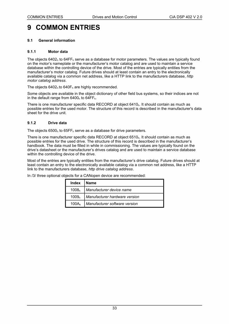
The objects 6402h to 64FFh serve as a database for motor parameters. The values are typically foundon the motor’s nameplate or the manufacturer’s motor catalog and are used to maintain a servicedatabase within the controlling device of the drive. Most of the entries are typically entities from themanufacturer’s motor catalog. Future drives should at least contain an entry to the electronicallyavailable catalog via a common net address, like a HTTP link to the manufacturers database, httpmotor catalog address.
The objects 6402h to 640Fh are highly recommended.
Some objects are available in the object dictionary of other field bus systems, so their indices are notin the default range from 6400h to 64FFh.
There is one manufacturer specific data RECORD at object 6410h. It should contain as much aspossible entries for the used motor. The structure of this record is described in the manufacturer's datasheet for the drive unit.
9.1.2 Drive data
The objects 6500h to 65FFh serve as a database for drive parameters.
There is one manufacturer specific data RECORD at object 6510h. It should contain as much aspossible entries for the used drive. The structure of this record is described in the manufacturer’shandbook. The data must be filled in while in commissioning. The values are typically found on thedrive’s datasheet or the manufacturer’s drives catalog and are used to maintain a service databasewithin the controlling device of the drive.
Most of the entries are typically entities from the manufacturer’s drive catalog. Future drives should atleast contain an entry to the electronically available catalog via a common net address, like a HTTPlink to the manufacturers database, http drive catalog address.
In /3/ three optional objects for a CANopen device are recommended:
Index Name
1008h Manufacturer device name
1009h Manufacturer hardware version
100Ah Manufacturer software version

COMMON ENTRIES Drives and Motion Control CiA DSP 402 V 2.0
34
9.2 Object dictionary entries
9.2.1 Objects defined in this chapter
Index Object Name Type Attr. M/O
6007h VAR Abort connection option code INTEGER16 rw O
603Fh VAR Error code UNSIGNED16 ro O
6402h VAR Motor type UNSIGNED16 rw O
6403h VAR Motor catalog number VISIBLE_STRING rw O
6404h VAR Motor manufacturer VISIBLE_STRING rw O
6405h VAR http motor catalog address VISIBLE_STRING rw O
6406h VAR Motor calibration date TIME_OF_DAY rw O
6407h VAR Motor service period UNSIGNED32 rw O
6410h RECORD Motor data (manufacturer specific) rw O
6502h VAR Supported drive modes UNSIGNED32 ro O
6503h VAR Drive catalog number VISIBLE_STRING ro O
6504h VAR Drive manufacturer VISIBLE_STRING ro O
6505h VAR http drive catalog address VISIBLE_STRING rw O
6510h RECORD Drive data (manufacturer specific) rw O
60FDh VAR Digital inputs UNSIGNED32 rw O
60FEh ARRAY Digital outputs UNSIGNED32 rw O
9.3 Object description
The drive functionality in error cases is adjustable by the following objects.
9.3.1 Object 6007h: Abort connection option code
The content of this object selects the function to be performed when the connection to the network islost.
OBJECT DESCRIPTION
INDEX 6007h
Name Abort connection option code
Object Code VAR
Data Type INTEGER16
Category Optional
ENTRY DESCRIPTION
Access rw
PDO Mapping Possible
Value Range INTEGER16
Default Value 0

COMMON ENTRIES Drives and Motion Control CiA DSP 402 V 2.0
35
DATA DESCRIPTION
Option code Meaning
0 no action
1 malfunction
2 Device control command ‘Disable Voltage’
3 Device control command ‘Quick Stop’
4..32767 reserved
-32768..–1 manufacturer specific
9.3.2 Object 603Fh: Error code
The Error code captures the code of the last error that occurred in the drive. It corresponds to thevalue of the lower 16 bits of object 1003h pre-defined error field.
OBJECT DESCRIPTION
INDEX 603Fh
Name Error code
Object Code VAR
Data Type UNSIGNED16
Category Optional
ENTRY DESCRIPTION
Access ro
PDO Mapping Possible
Value Range UNSIGNED16
Default Value 0
9.3.3 Object 6402h: Motor type
The type of motor driven by the controller.
OBJECT DESCRIPTION
INDEX 6402h
Name Motor type
Object Code VAR
Data Type UNSIGNED16
Category Optional
ENTRY DESCRIPTION
Access rw
PDO Mapping Possible
Value Range UNSIGNED16
Default Value No

COMMON ENTRIES Drives and Motion Control CiA DSP 402 V 2.0
36
DATA DESCRIPTION
Value Motor Type
0000h Non-standard motor
0001h Phase modulated DC motor
0002h Frequency controlled DC motor
0003h PM synchronous motor
0004h FC synchronous motor
0005h Switched reluctance motor
0006h Wound rotor induction motor
0007h Squirrel cage induction motor
0008h Stepper motor
0009h Micro-step stepper motor
000Ah Sinusoidal PM BL motor
000Bh Trapezoidal PM BL motor
000Ch reserved
::::: :::::
7FFFh reserved
8000h manufacturer specific
::::: :::::
FFFFh manufacturer specific
9.3.4 Object 6403h: Motor catalog number
The manufacturer's motor catalog number (nameplate number).
OBJECT DESCRIPTION
INDEX 6403h
Name Motor catalog number
Object Code VAR
Data Type VISIBLE_STRING
Category Optional
ENTRY DESCRIPTION
Access rw
PDO Mapping No
Value Range No
Default Value No

COMMON ENTRIES Drives and Motion Control CiA DSP 402 V 2.0
37
9.3.5 Object 6404h: Motor manufacturer
The motor manufacturer's name.
OBJECT DESCRIPTION
INDEX 6404h
Name Motor manufacturer
Object Code VAR
Data Type VISIBLE_STRING
Category Optional
ENTRY DESCRIPTION
Access rw
PDO Mapping No
Value Range No
Default Value No
9.3.6 Object 6405h: http motor catalog address
OBJECT DESCRIPTION
INDEX 6405h
Name http motor catalog address
Object Code VAR
Data Type VISIBLE_STRING
Category Optional
ENTRY DESCRIPTION
Access rw
PDO Mapping No
Value Range No
Default Value No
9.3.7 Object 6406h: Motor calibration date
Date of the last motor inspection.
OBJECT DESCRIPTION
INDEX 6406h
Name Motor calibration date
Object Code VAR
Data Type TIME_OF_DAY
Category Optional
ENTRY DESCRIPTION
Access rw
PDO Mapping Possible
Value Range No
Default Value No

COMMON ENTRIES Drives and Motion Control CiA DSP 402 V 2.0
38
9.3.8 Object 6407h: Motor service period
Value in hours of the nominal motor lifetime. The motor needs service after this time.
OBJECT DESCRIPTION
INDEX 6407h
Name Motor service period
Object Code VAR
Data Type UNSIGNED32
Category Optional
ENTRY DESCRIPTION
Access rw
PDO Mapping Possible
Value Range UNSIGNED32
Default Value No
9.3.9 Object 6410h: Motor data
This object contains as much as possible information about the connected motor. The structure of thisrecord is described in the drive manufacturer’s handbook.
OBJECT DESCRIPTION
INDEX 6410h
Name Motor data
Object Code RECORD
Data Type manufacturer specific
Category Optional
ENTRY DESCRIPTION
Sub-Index 0
Description Number of entries
Entry category Mandatory
Access ro
PDO Mapping No
Value Range 1 … 254
Default Value No
Sub-Index 1
Description manufacturer specific
Entry category Mandatory
Access rw
PDO Mapping Possible
Value Range No
Default Value No

COMMON ENTRIES Drives and Motion Control CiA DSP 402 V 2.0
39
Sub-Index 2
Description manufacturer specific
Entry category Optional
Access rw
PDO Mapping Possible
Value Range No
Default Value No
to
Sub-Index 254
Description manufacturer specific
Entry category Optional
Access rw
PDO Mapping Possible
Value Range No
Default Value No
9.3.10 Object 6502h: Supported drive modes
A drive can support more then one and several distinct modes of operation. This object gives anoverview of the implemented operating modes in the device. This object is read only.
OBJECT DESCRIPTION
INDEX 6502h
Name Supported drive modes
Object Code VAR
Data Type UNSIGNED32
Category Optional
ENTRY DESCRIPTION
Access ro
PDO Mapping Possible
Value Range UNSIGNED32
Default Value No
DATA DESCRIPTION31 16 15 7 6 5 4 3 2 1 0
manufacturer specific reserved ip hm reserved tq pv vl pp
MSB LSB

COMMON ENTRIES Drives and Motion Control CiA DSP 402 V 2.0
40
9.3.11 Object 6503h: Drive catalog number
The manufacturer's drive catalog number (nameplate number).
OBJECT DESCRIPTION
INDEX 6503h
Name Drive catalog number
Object Code VAR
Data Type VISIBLE_STRING
Category Optional
ENTRY DESCRIPTION
Access rw
PDO Mapping No
Value Range No
Default Value No
9.3.12 Object 6504h: Drive manufacturer
The drive manufacturer's name.
OBJECT DESCRIPTION
INDEX 6504h
Name Drive manufacturer
Object Code VAR
Data Type VISIBLE_STRING
Category Optional
ENTRY DESCRIPTION
Access rw
PDO Mapping No
Value Range No
Default Value No
9.3.13 Object 6505h: http drive catalog address
The internet address of the manufacturer.
OBJECT DESCRIPTION
INDEX 6505h
Name http drive catalog address
Object Code VAR
Data Type VISIBLE_STRING
Category Optional
COMMON ENTRIES Drives and Motion Control CiA DSP 402 V 2.0
41
ENTRY DESCRIPTION
Access rw
PDO Mapping No
Value Range No
Default Value No
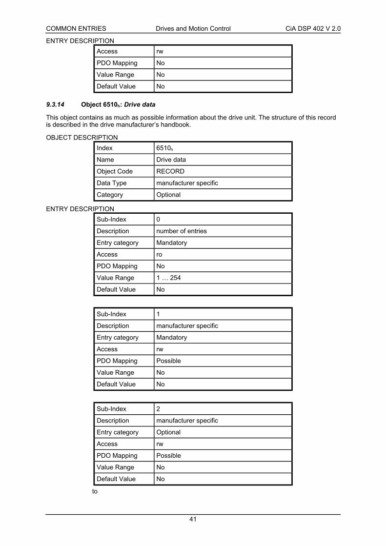
9.3.14 Object 6510h: Drive data
This object contains as much as possible information about the drive unit. The structure of this recordis described in the drive manufacturer’s handbook.
OBJECT DESCRIPTION
Index 6510h
Name Drive data
Object Code RECORD
Data Type manufacturer specific
Category Optional
ENTRY DESCRIPTION
Sub-Index 0
Description number of entries
Entry category Mandatory
Access ro
PDO Mapping No
Value Range 1 … 254
Default Value No
Sub-Index 1
Description manufacturer specific
Entry category Mandatory
Access rw
PDO Mapping Possible
Value Range No
Default Value No
Sub-Index 2
Description manufacturer specific
Entry category Optional
Access rw
PDO Mapping Possible
Value Range No
Default Value No
to

COMMON ENTRIES Drives and Motion Control CiA DSP 402 V 2.0
42
Sub-Index 254
Description manufacturer specific
Entry category Optional
Access rw
PDO Mapping Possible
Value Range No
Default Value No
9.3.15 Object 60FDh: Digital inputs
This index defines simple digital inputs for drives. The user may apply any signals to these inputs forspecial purposes like limit or reference switches.
OBJECT DESCRIPTION
INDEX 60FDh
Name Digital inputs
Object Code VAR
Data Type UNSIGNED32
Category Optional
ENTRY DESCRIPTION
Access ro
PDO Mapping Possible
Value Range UNSIGNED32
Default Value 0
DATA DESCRIPTION31 16 15 4 3 2 1 0
manufacturer specific reserved interlock home switch positive limitswitch
negativelimit switch
MSB LSB
The switch have to be "active high".
9.3.16 Object 60FEh: Digital outputs
This index defines simple digital outputs for drives.
OBJECT DESCRIPTION
Index 60FEh
Name Digital outputs
Object Code ARRAY
Data Type UNSIGNED32
Category Optional

COMMON ENTRIES Drives and Motion Control CiA DSP 402 V 2.0
43
ENTRY DESCRIPTION
Sub-Index 0
Description number of entries
Entry description Mandatory
Access ro
PDO Mapping No
Value Range 1 … 2
Default Value No
Sub-Index 1
Description Physical outputs
Entry description Mandatory
Access rw
PDO Mapping Possible
Value Range UNSIGNED32
Default Value 0
Sub-Index 2
Description Bit mask
Entry description Optional
Access rw
PDO Mapping Possible
Value Range UNSIGNED32
Default Value 0
DATA DESCRIPTIONThe first sub-index defines the assigned outputs.
31 16 15 1 0
manufacturer specific reserved set brake
MSB LSB
The second sub-index describes a mask to specify which of the outputs shall be used:
0 - Output is disabled
1 - Output is enabled

DEVICE CONTROL Drives and Motion Control CiA DSP 402 V 2.0
44
10 DEVICE CONTROL
10.1 General information
The device control function block controls all functions of the drive (drive function and power section).It is divided into:
• device control of the state machine
• operation mode function
Device Controlling
Operation Mode State Machine
controlword(6040h)
statusword(6041h)
Remote
Terminals
Fault
modes_of_operation(6060h)
Figure 5: Device controlling
The state of the drive can be controlled by the controlword.
The state of the drive is shown in the statusword.
In remote mode the device is controlled directly from the CANopen network by PDO and SDO.
The state machine is controlled externally by the controlword and external signals. The write access tothe controlword is controlled by the optional hardware signal 'Remote'. The state machine is alsocontrolled by internal signals like faults and modes of operation.
State MachineFaults
Status of the Drive Function
statusword(6041h)
Logical Operation
controlword(6040h)
Remote
Terminals
Figure 6: Remote mode

DEVICE CONTROL Drives and Motion Control CiA DSP 402 V 2.0
45
10.1.1 State machine
The state machine describes the device status and the possible control sequence of the drive. A singlestate represents a special internal or external behavior. The state of the drive also determines whichcommands are accepted. E.g. it is only possible to start a point-to-point move when the drive is instate OPERATION ENABLE.
States may be changed using the controlword and/or according to internal events. The current statecan be read using the statusword.
State Machine
controlword(6040h)
statusword(6041h)Actions
InternalEvents
Figure 7: State machine in system context
The state machine in Figure 7 describes the state machine of the device with respect to control of thepower electronics as a result of user commands and internal drive faults.
Start
Not Ready toSwitch On
Switch OnDisabled
Ready toSwitch On
Switched On
OperationEnable
FaultReaction Active
Fault
QuickStopActiv
PowerDisabled
PowerEnabled
Fault
9
16
11
8
0
1
72
3 6
54
1210
15
14
13
Figure 8: State machine
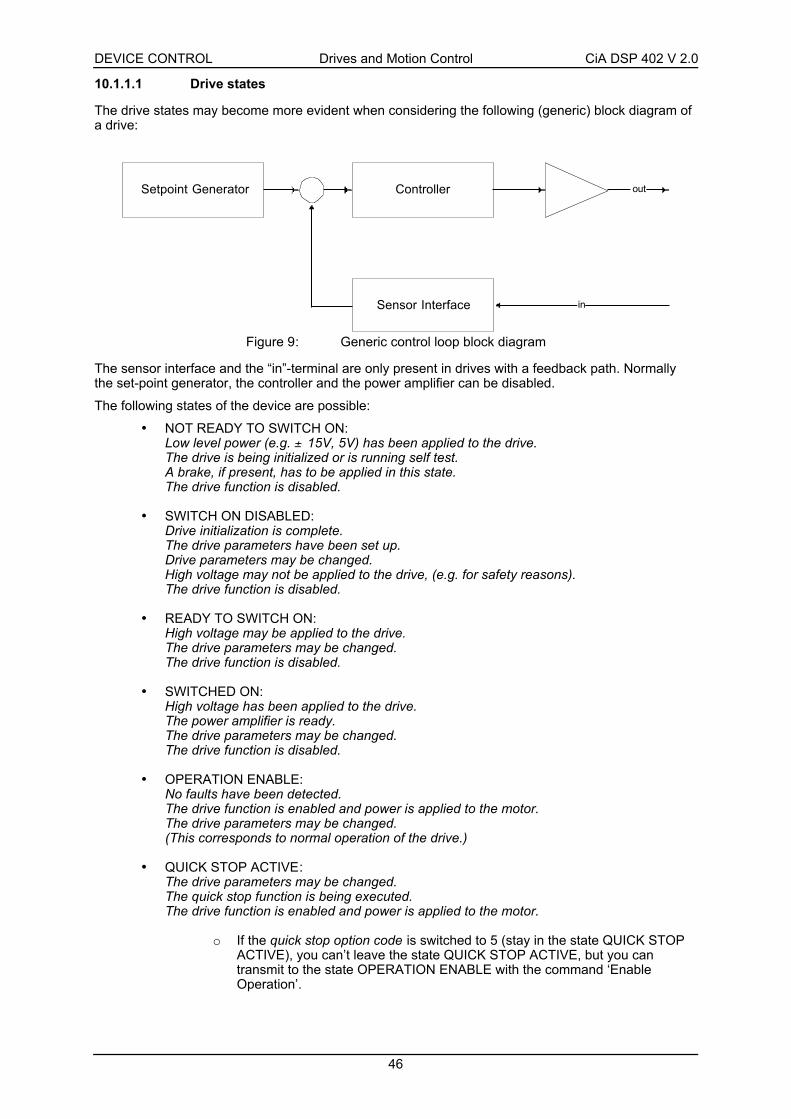
DEVICE CONTROL Drives and Motion Control CiA DSP 402 V 2.0
46
10.1.1.1 Drive states
The drive states may become more evident when considering the following (generic) block diagram ofa drive:
Setpoint Generator Controller
inSensor Interface
out
Figure 9: Generic control loop block diagram
The sensor interface and the “in”-terminal are only present in drives with a feedback path. Normallythe set-point generator, the controller and the power amplifier can be disabled.
The following states of the device are possible:
• NOT READY TO SWITCH ON:Low level power (e.g. ± 15V, 5V) has been applied to the drive.The drive is being initialized or is running self test.A brake, if present, has to be applied in this state.The drive function is disabled.
• SWITCH ON DISABLED:Drive initialization is complete.The drive parameters have been set up.Drive parameters may be changed.High voltage may not be applied to the drive, (e.g. for safety reasons).The drive function is disabled.
• READY TO SWITCH ON:High voltage may be applied to the drive.The drive parameters may be changed.The drive function is disabled.
• SWITCHED ON:High voltage has been applied to the drive.The power amplifier is ready.The drive parameters may be changed.The drive function is disabled.
• OPERATION ENABLE:No faults have been detected.The drive function is enabled and power is applied to the motor.The drive parameters may be changed.(This corresponds to normal operation of the drive.)
• QUICK STOP ACTIVE:The drive parameters may be changed.The quick stop function is being executed.The drive function is enabled and power is applied to the motor.
o If the quick stop option code is switched to 5 (stay in the state QUICK STOPACTIVE), you can’t leave the state QUICK STOP ACTIVE, but you cantransmit to the state OPERATION ENABLE with the command ‘EnableOperation’.
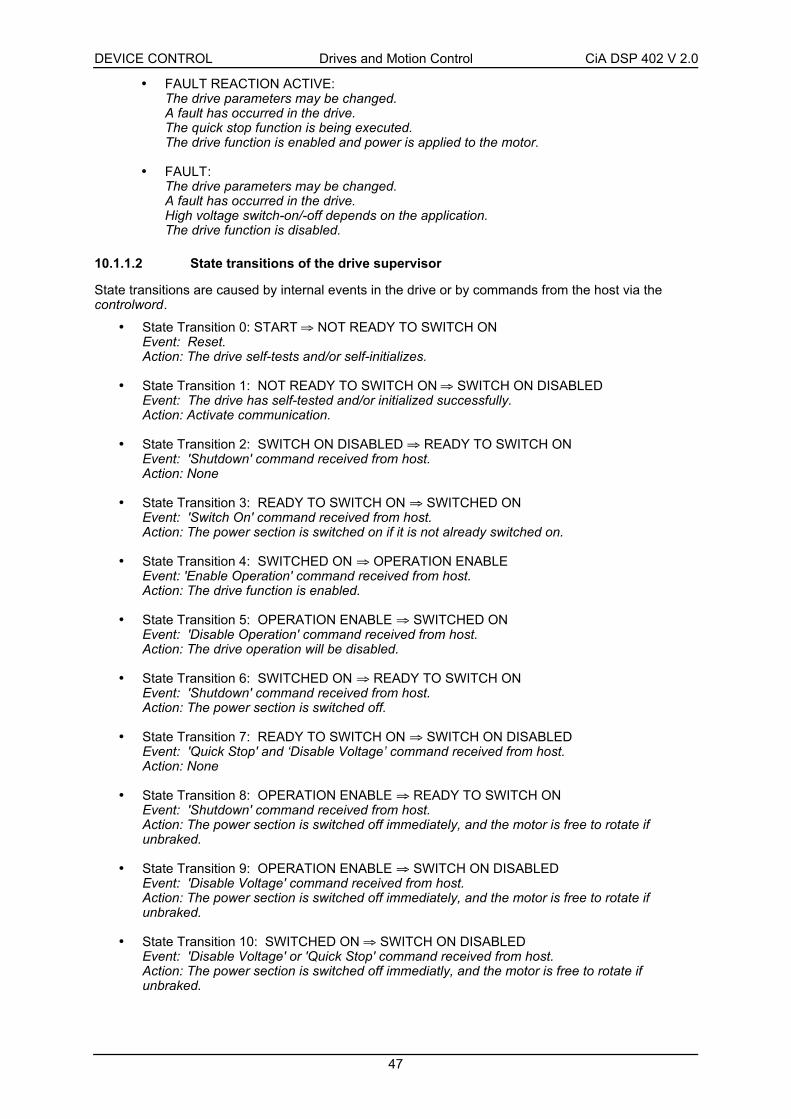
DEVICE CONTROL Drives and Motion Control CiA DSP 402 V 2.0
47
• FAULT REACTION ACTIVE:The drive parameters may be changed.A fault has occurred in the drive.The quick stop function is being executed.The drive function is enabled and power is applied to the motor.
• FAULT:The drive parameters may be changed.A fault has occurred in the drive.High voltage switch-on/-off depends on the application.The drive function is disabled.
10.1.1.2 State transitions of the drive supervisor
State transitions are caused by internal events in the drive or by commands from the host via thecontrolword.
• State Transition 0: START ⇒ NOT READY TO SWITCH ONEvent: Reset.Action: The drive self-tests and/or self-initializes.
• State Transition 1: NOT READY TO SWITCH ON ⇒ SWITCH ON DISABLEDEvent: The drive has self-tested and/or initialized successfully.Action: Activate communication.
• State Transition 2: SWITCH ON DISABLED ⇒ READY TO SWITCH ONEvent: 'Shutdown' command received from host.Action: None
• State Transition 3: READY TO SWITCH ON ⇒ SWITCHED ONEvent: 'Switch On' command received from host.Action: The power section is switched on if it is not already switched on.
• State Transition 4: SWITCHED ON ⇒ OPERATION ENABLEEvent: 'Enable Operation' command received from host.Action: The drive function is enabled.
• State Transition 5: OPERATION ENABLE ⇒ SWITCHED ONEvent: 'Disable Operation' command received from host.Action: The drive operation will be disabled.
• State Transition 6: SWITCHED ON ⇒ READY TO SWITCH ONEvent: 'Shutdown' command received from host.Action: The power section is switched off.
• State Transition 7: READY TO SWITCH ON ⇒ SWITCH ON DISABLEDEvent: 'Quick Stop' and ‘Disable Voltage’ command received from host.Action: None
• State Transition 8: OPERATION ENABLE ⇒ READY TO SWITCH ONEvent: 'Shutdown' command received from host.Action: The power section is switched off immediately, and the motor is free to rotate ifunbraked.
• State Transition 9: OPERATION ENABLE ⇒ SWITCH ON DISABLEDEvent: 'Disable Voltage' command received from host.Action: The power section is switched off immediately, and the motor is free to rotate ifunbraked.
• State Transition 10: SWITCHED ON ⇒ SWITCH ON DISABLEDEvent: 'Disable Voltage' or 'Quick Stop' command received from host.Action: The power section is switched off immediatly, and the motor is free to rotate ifunbraked.
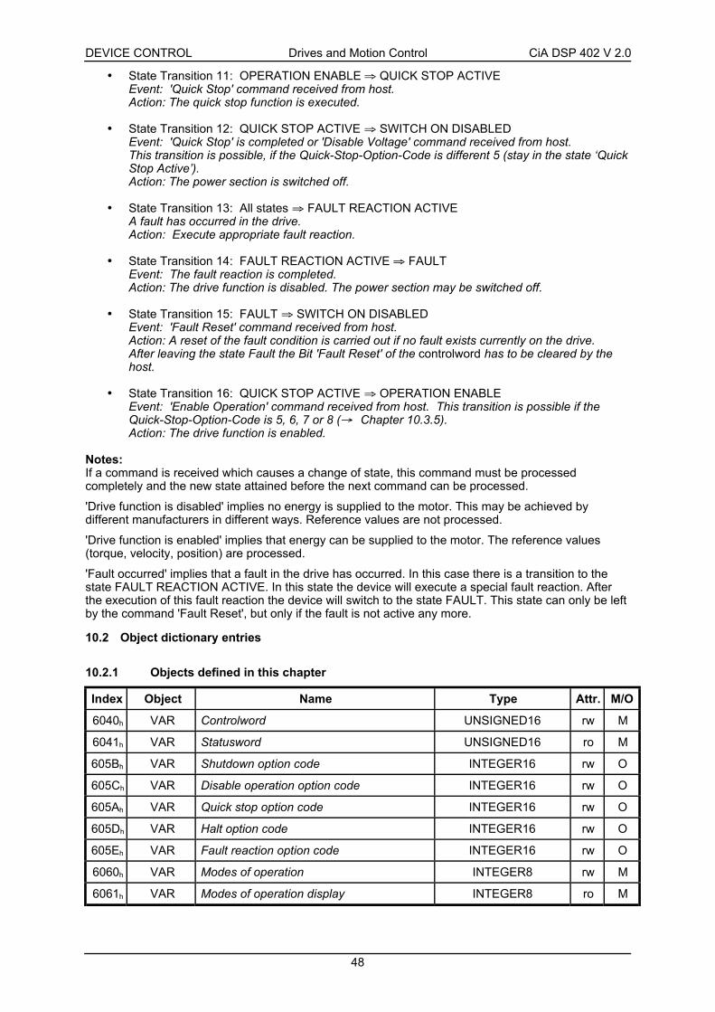
DEVICE CONTROL Drives and Motion Control CiA DSP 402 V 2.0
48
• State Transition 11: OPERATION ENABLE ⇒ QUICK STOP ACTIVEEvent: 'Quick Stop' command received from host.Action: The quick stop function is executed.
• State Transition 12: QUICK STOP ACTIVE ⇒ SWITCH ON DISABLEDEvent: 'Quick Stop' is completed or 'Disable Voltage' command received from host.This transition is possible, if the Quick-Stop-Option-Code is different 5 (stay in the state ‘QuickStop Active’).Action: The power section is switched off.
• State Transition 13: All states ⇒ FAULT REACTION ACTIVEA fault has occurred in the drive.Action: Execute appropriate fault reaction.
• State Transition 14: FAULT REACTION ACTIVE ⇒ FAULTEvent: The fault reaction is completed.Action: The drive function is disabled. The power section may be switched off.
• State Transition 15: FAULT ⇒ SWITCH ON DISABLEDEvent: 'Fault Reset' command received from host.Action: A reset of the fault condition is carried out if no fault exists currently on the drive.After leaving the state Fault the Bit 'Fault Reset' of the controlword has to be cleared by thehost.
• State Transition 16: QUICK STOP ACTIVE ⇒ OPERATION ENABLEEvent: 'Enable Operation' command received from host. This transition is possible if theQuick-Stop-Option-Code is 5, 6, 7 or 8 (→ Chapter 10.3.5).Action: The drive function is enabled.
Notes:If a command is received which causes a change of state, this command must be processedcompletely and the new state attained before the next command can be processed.
'Drive function is disabled' implies no energy is supplied to the motor. This may be achieved bydifferent manufacturers in different ways. Reference values are not processed.
'Drive function is enabled' implies that energy can be supplied to the motor. The reference values(torque, velocity, position) are processed.
'Fault occurred' implies that a fault in the drive has occurred. In this case there is a transition to thestate FAULT REACTION ACTIVE. In this state the device will execute a special fault reaction. Afterthe execution of this fault reaction the device will switch to the state FAULT. This state can only be leftby the command 'Fault Reset', but only if the fault is not active any more.
10.2 Object dictionary entries
10.2.1 Objects defined in this chapter
Index Object Name Type Attr. M/O
6040h VAR Controlword UNSIGNED16 rw M
6041h VAR Statusword UNSIGNED16 ro M
605Bh VAR Shutdown option code INTEGER16 rw O
605Ch VAR Disable operation option code INTEGER16 rw O
605Ah VAR Quick stop option code INTEGER16 rw O
605Dh VAR Halt option code INTEGER16 rw O
605Eh VAR Fault reaction option code INTEGER16 rw O
6060h VAR Modes of operation INTEGER8 rw M
6061h VAR Modes of operation display INTEGER8 ro M

DEVICE CONTROL Drives and Motion Control CiA DSP 402 V 2.0
49
10.3 Object description
10.3.1 Object 6040h: Controlword
The controlword consist of bits for:
• the controlling of the state,
• the controlling of operating modes and
• manufacturer specific options.
OBJECT DESCRIPTION
INDEX 6040h
Name Controlword
Object Code VAR
Data Type UNSIGNED16
Category Mandatory
ENTRY DESCRIPTION
Access rw
PDO Mapping Possible
Value Range UNSIGNED16
Default Value No
DATA DESCRIPTIONThe bits of the controlword are defined as follows:
15 11 10 9 8 7 6 4 3 2 1 0
manufacturerspecific
reserved halt Faultreset
Operationmode specific
Enableoperation
Quickstop
Enablevoltage
Switchon
O O O M O M M M M
MSB LSB
0 - Optional M - Mandatory
BITS 0 – 3 AND 7:
Device control commands are triggered by the following bit patterns in the controlword:
Bit of the controlwordCommand
Fault reset Enableoperation
Quickstop
Enablevoltage
Switch onTransitions
Shutdown 0 X 1 1 0 2,6,8
Switch on 0 0 1 1 1 3*
Switch on 0 1 1 1 1 3**
Disable voltage 0 X X 0 X 7,9,10,12
Quick stop 0 X 0 1 X 7,10,11
Disable operation 0 0 1 1 1 5
Enable operation 0 1 1 1 1 4,16
Fault reset X X X X 15
Table 4: Device control commands (bits marked X are irrelevant, * ... In the stateSWITCHED ON the drive executes the functionality of this state., ** ... It exists no functionality
in the state SWITCHED ON. The drive does not do any in this state.)

DEVICE CONTROL Drives and Motion Control CiA DSP 402 V 2.0
50
BITS 4, 5, 6 AND 8:
These bits are operation mode specific. The description is situated in the chapter of the special mode.The following table gives an overview:
Operation modeBit
Velocitymode
Profileposition mode
Profile velocitymode
Profiletorque mode
Homingmode
Interpolationposition mode
4 rfg enable New set-point reserved reserved Homingoperation
start
Enable ipmode
5 rfg unlock Change setimmediately
reserved reserved reserved reserved
6 rfg use ref abs / rel reserved reserved reserved reserved
8 Halt Halt Halt Halt Halt Halt
Table 5: Mode specific bits in the controlword
BITS 9, 10:
These bits are reserved for further use. They are inactive by setting to zero. If they have no specialfunction, they must be set to zero.
BITS 11, 12, 13, 14 AND 15:
These bits are manufacturer specific.
10.3.2 Object 6041h: Statusword
The statusword indicates the current state of the drive. No bits are latched. The statusword consist ofbits for:
• the current state of the drive,
• the operating state of the mode and
• manufacturer specific options.
OBJECT DESCRIPTION
INDEX 6041h
Name Statusword
Object Code VAR
Data Type UNSIGNED16
Category Mandatory
ENTRY DESCRIPTION
Access ro
PDO Mapping Possible
Value Range UNSIGNED16
Default Value No
DATA DESCRIPTION
15 14 13 12 11 10 9 8 7 6 5 4 3 2 1 0
MSB LSB

DEVICE CONTROL Drives and Motion Control CiA DSP 402 V 2.0
51
Bit Description M /O
0 Ready to switch on M
1 Switched on M
2 Operation enabled M
3 Fault M
4 Voltage enabled M
5 Quick stop M
6 Switch on disabled M
7 Warning O
8 Manufacturer specific O
9 Remote M
10 Target reached M
11 Internal limit active M
12 - 13 Operation mode specific O
14 - 15 Manufacturer specific O
Table 6: Bits in the statusword
BITS 0 – 3, 5 AND 6:
The following bits indicate the status of the device:
Value (binary) State
xxxx xxxx x0xx 0000 Not ready to switch on
xxxx xxxx x1xx 0000 Switch on disabled
xxxx xxxx x01x 0001 Ready to switch on
xxxx xxxx x01x 0011 Switched on
xxxx xxxx x01x 0111 Operation enabled
xxxx xxxx x00x 0111 Quick stop active
xxxx xxxx x0xx 1111 Fault reaction active
xxxx xxxx x0xx 1000 Fault
Table 7: Device state bits (x ... irrelevant for this state)
BIT 4: VOLTAGE ENABLED
High voltage is applied to the drive when this bit is set to 1.
BIT 5: QUICK STOP
When reset, this bit indicates that the drive is reacting on a quick stop request. Bits 0, 1 and 2 of thestatusword must be set to 1 to indicate that the drive is capable to regenerate. The setting of the otherbits indicates the status of the drive (e.g. the drive is performing a quick stop as result of a reaction toa non-fatal fault. The fault bit is set as well as bits 0, 1 and 2).
BIT 7: WARNING
A drive warning is present if bit 7 is set. The cause means no error but a state that has to bementioned, e.g. temperature limit, job refused. The status of the drive does not change. The cause ofthis warning may be found by reading the fault code parameter. The bit is set and reset by the device.
BIT 8:
This bit may be used by a drive manufacturer to implement any manufacturer specific functionality.

DEVICE CONTROL Drives and Motion Control CiA DSP 402 V 2.0
52
BIT 9: REMOTE
If bit 9 is set, then parameters may be modified via the CAN-network, and the drive executes thecontent of a command message. If the bit remote is reset, then the drive is in local mode and will notexecute the command message. The drive may transmit messages containing valid actual values likea position actual value, depending on the actual drive configuration. The drive will accept accesses viaSDO in local mode.
BIT 10: TARGET REACHED
If bit 10 is set by the drive, then a set-point has been reached. The set-point is dependent on theoperating mode. The description is situated in the chapter of the special mode. The change of a targetvalue by software alters this bit.
If quick stop option code is 5, 6, 7 or 8, this bit must be set, when the quick stop operation is finishedand the drive is halted.
If halt occurred and the drive has halted then this bit is set too.
BIT 11: INTERNAL LIMIT ACTIVE
This bit set by the drive indicates, that an internal limitation is active (e.g. position range limit).
BIT 12 AND 13:
These bits are operation mode specific. The description is situated in the chapter of the special modeThe following table gives an overview:
Operation modeBit
vl pp pv tq hm ip
12 reserved Set-pointacknowledge
Speed reserved Homingattained
ip modeactive
13 reserved Followingerror
Max slippageerror
reserved Homing error reserved
Table 8: Mode specific bits in the statusword
BIT 14 AND 15:
These bits may be used by a drive manufacturer to implement any manufacturer specific functionality.
10.3.3 Object 605Bh: Shutdown option code
The parameter shutdown option code determines what action should be taken if there is a transition
OPERATION ENABLE ⇒ READY TO SWITCH ON.
OBJECT DESCRIPTION
INDEX 605Bh
Name Shutdown option code
Object Code VAR
Data Type INTEGER16
Category Optional
ENTRY DESCRIPTION
Access rw
PDO Mapping No
Value Range INTEGER16
Default Value 0

DEVICE CONTROL Drives and Motion Control CiA DSP 402 V 2.0
53
DATA DESCRIPTION
Value Description
-32768 ... –1 manufacturer specific
0 Disable drive function
1 Slow down with slow down ramp; disable of the drive function
2 ... 32767 reserved
10.3.4 Object 605Ch: Disable operation option code
The parameter disable operation option code determines what action should be taken if there is atransition
OPERATION ENABLE ⇒ SWITCHED ON.
OBJECT DESCRIPTION
INDEX 605Ch
Name Disable operation option code
Object Code VAR
Data Type INTEGER16
Category Optional
ENTRY DESCRIPTION
Access rw
PDO Mapping No
Value Range INTEGER16
Default Value 1
DATA DESCRIPTION
Value Description
-32768 ... -1 manufacturer specific
0 Disable drive function
1 Slow down with slow down ramp and then disabling of the drive function
2 ... 32767 reserved
10.3.5 Object 605Ah: Quick stop option code
The parameter quick stop option code determines what action should be taken if the Quick StopFunction is executed.
OBJECT DESCRIPTION
INDEX 605Ah
Name Quick stop option code
Object Code VAR
Data Type INTEGER16
Category Optional

DEVICE CONTROL Drives and Motion Control CiA DSP 402 V 2.0
54
ENTRY DESCRIPTION
Access rw
PDO Mapping No
Value Range INTEGER16
Default Value 2
DATA DESCRIPTION
Value Description
-32768 ... -1 manufacturer Specific
0 disable drive function
1 slow down on slow down ramp
2 slow down on quick stop ramp
3 slow down on the current limit
4 slow down on the voltage limit
5 slow down on slow down ramp and stay in QUICK STOP
6 slow down on quick stop ramp and stay in QUICK STOP
7 slow down on the current limit and stay in QUICK STOP
8 slow down on the voltage limit and stay in QUICK STOP
9 ... 32767 Reserved
10.3.6 Object 605Dh: Halt option code
The parameter halt option code determines what action should be taken if the bit 8 (halt) in thecontrolword is active.
OBJECT DESCRIPTION
INDEX 605Dh
Name Halt option code
Object Code VAR
Data Type INTEGER16
Category Optional
ENTRY DESCRIPTION
Access rw
PDO Mapping No
Value Range INTEGER16
Default Value 1
DATA DESCRIPTION
Value Description
-32768 ... -1 manufacturer Specific
0 disable drive, motor is free to rotate
1 slow down on slow down ramp
2 slow down on quick stop ramp

DEVICE CONTROL Drives and Motion Control CiA DSP 402 V 2.0
55
Value Description
3 slow down on the current limit
4 slow down on the voltage limit
5 ... 32767 reserved
10.3.7 Object 605Eh: Fault reaction option code
The parameter fault reaction option code determines what action should be taken if a fault occurs inthe drive.
OBJECT DESCRIPTION
INDEX 605Eh
Name Fault reaction option code
Object Code VAR
Data Type INTEGER16
Category Optional
ENTRY DESCRIPTION
Access rw
PDO Mapping No
Value Range INTEGER16
Default Value 2
DATA DESCRIPTION
Value Description
-32768 ... -1 manufacturer specific
0 disable drive, motor is free to rotate
1 slow down on slow down ramp
2 slow down on quick stop ramp
3 slow down on the current limit
4 slow down on the voltage limit
5 ... 32767 reserved
10.3.8 Object 6060h: Modes of operation
The parameter modes of operation switches the actually choosen operation mode.
OBJECT DESCRIPTION
INDEX 6060h
Name Modes of operation
Object Code VAR
Data Type INTEGER8
Category Mandatory

DEVICE CONTROL Drives and Motion Control CiA DSP 402 V 2.0
56
ENTRY DESCRIPTION
Access rw
PDO Mapping Possible
Value Range INTEGER8
Default Value No
DATA DESCRIPTION
Value Description
-1 ... -128 manufacturer specific modes of operation
0 reserved
1 Profile Position Mode
2 Velocity Mode
3 Profile Velocity Mode
4 Torque Profile Mode
5 reserved
6 Homing Mode
7 Interpolated Position Mode
8 ... 127 reserved
NOTEA read of modes of operation shows only the value of modes of operation. The actual mode of thedrive is reflected in the object modes of operation display. It may be changed by writing to modes ofoperation.
10.3.9 Object 6061h: Modes of operation display
The modes of operation display shows the current mode of operation. The meaning of the returnedvalue corresponds to that of the modes of operation option code (index 6060h).
OBJECT DESCRIPTION
INDEX 6061h
Name Modes of operation display
Object Code VAR
Data Type INTEGER8
Category Mandatory
ENTRY DESCRIPTION
Access ro
PDO Mapping Possible
Value Range INTEGER8
Default Value No
DATA DESCRIPTIONSame as for object 6060h modes of operation.
NOTEThe actual mode is reflected in the modes of operation display (index 6061h), and not in the modes ofoperation (index 6060h).

DEVICE CONTROL Drives and Motion Control CiA DSP 402 V 2.0
57
10.4 Functional description
10.4.1 Modes of operation function
The device behavior depends on the activated modes of operation.
It is possible to implement different device modes. Since it is not possible to operate the modes inparallel, the user is able to activate the required function by selecting a mode of operation. An exampleof exclusive functions are those for position and torque control, which can only control one variable atany one time. The variables can perform at most a limited function. Such hybrids are regarded as theparticular characteristics of a mode of operation. Position control operation and encoder profile supportcan be active at the same time, for example. Consequently encoder profile support is not regarded asa mode of operation.
OperationMode
Function
modes_of_operation_display(6061h)
modes_of_operation(6060h)
Velocity Mode
Profile Velocity Mode
Profile Torque Mode
Figure 10: Operation mode function
It is possible for the user to switch between the various modes of operation as long as this issupported by the device. It is possible for the manufacturer to allow dynamic switching betweendifferent modes of operation at any time or to limit switching for example to the state SWITCHED ON.Switching can also be limited to the state 'local control'; i.e. not possible via the CAN-network. Adevice characteristic listed in the device function list can possible have several modes of operation.
The following modes of operation are listed:
• Velocity Mode (AC/DC drives, no feedback)• Profile Velocity Mode (servo drives, feedback)• Torque Profile Mode• Homing Mode• Profile Position Mode• Interpolated Position Mode
With the exception of the ‘Homing Mode’, these listed modes of operation can all be put under theheading of 'set-point setting'.
In parallel to this, manufacturer-specific modes of operation may also be available. These are notlimited to set-point settings.
The reference operation is regarded as a special form of a program function. The program functionallows the user to run complex of time-critical sequence, e. g. tool change or special referenceoperations, directly in the device.
The switching between the modes of operation listed above should not incur any automaticreconfiguration of the process data channel. Problems which occur through switching of set-pointvalues during change of operating modes must be monitored by the user. If necessary they can berectified by prior reconfiguration of the process data channel.
Two objects are defined for management of the modes of operation:
• modes of operation
• modes of operation display
The statusword contains bits, whose meaning is dependent on the mode of operation. When switchingthe mode of operation, the bits changing their meaning need to be monitored.

DEVICE CONTROL Drives and Motion Control CiA DSP 402 V 2.0
58
10.4.2 Drive disabling function
The drive disabling function defines the behavior of the drive when transitioning from the stateOPERATION ENABLE to the state READY TO SWITCH ON (‘Shutdown’ command) or the stateSWITCHED ON (‘Disable Operation’ command).
Figure 11: Modes of operation function
10.4.3 Quick stop function
The quick stop function is triggered by the ‘Quick Stop’ command.
Figure 12: Quick stop function
10.4.4 Stop function
The stop function may be triggered by resetting the bit 'RFG-disable' in the controlword.
Figure 13: Stop function
Drive disablingfunction
State transition 5 + 8
status word (0641h)
shutdown option code (605Bh)
disable operation option code (605Ch)
Quick stop function
State transition 11
Action
quick stop option code (605Ah)
Stop function
statusword / bit 8 = 1
Action
stop option code (605Dh)

DEVICE CONTROL Drives and Motion Control CiA DSP 402 V 2.0
59
10.4.5 Fault reaction
Drive faults may be classified as fatal or non-fatal faults.
10.4.5.1 Fatal faults
When a fatal fault occurs, the drive is no longer able to control the motor, so an immediate switch-offof the drive is necessary.
10.4.5.2 Non-fatal faults
When a non-fatal fault occurs, the drive can run the motor in a controlled fashion. The actions whichare executed depend on the fault reaction option code.
Once a fault occurs the drive will always enter the FAULT state, even if the fault clears before the driveenters the FAULT state. The FAULT state may only be left if the 'Fault Reset' command is receivedfrom a host, and no further fault is present in the drive.

FACTOR GROUP Drives and Motion Control CiA DSP 402 V 2.0
60
11 FACTOR GROUP
11.1 General information
11.1.1 Factors
There is a need to interchange physical dimensions and sizes into the device internal units. Toimplement the interchange, several factors are necessary. This chapter describes how these factorshave an influence on the system, how they are calculated and which data is necessary to build them.Normalized parameters are denoted with an asterisk *.
feed constant (6092h)gear ratio (6091h)
velocity_enocder_resolution(6090h)position_encoder_resolution(608F)
notation indexdimension index
normalisingfactor
value*factor
calculation
value/factor
physical input
normalised input*
normalised output*
physical output
dimension specific factor selection
Figure 14: Influence of factors
11.1.2 Relationship between physical and internal units
The factors defined in the factor group set up a relationship between device internal units and physicalunits.
The factors are result of the calculation of two parameters called dimension index and notation index,which are defined in Table D (see appendix Definition of dimension indices). One parameter indicatesthe physical dimension, the other the decimal exponent for the values. These factors are directly usedto normalize the physical values.
The application specific parameters will be used in the corresponding mode of operation to build thedescribed factors.
Parameters that are commonly used will be integrated in the object dictionary without defining theirjunctions. This guaranties a common parameter number for further use without the need for apredefinition.

FACTOR GROUP Drives and Motion Control CiA DSP 402 V 2.0
61
11.2 Object dictionary entries
11.2.1 Objects defined in this chapter
Index Object Name Type Attr. M/O
6089h VAR Position notation index INTEGER8 rw O
608Ah VAR Position dimension index UNSIGNED8 rw O
608Bh VAR Velocity notation index INTEGER8 rw O
608Ch VAR Velocity dimension index UNSIGNED8 rw O
608Dh VAR Acceleration notation index INTEGER8 rw O
608Eh VAR Acceleration dimension index UNSIGNED8 rw O
608Fh ARRAY Position encoder resolution UNSIGNED32 rw O
6090h ARRAY Velocity encoder resolution UNSIGNED32 rw O
6091h ARRAY Gear ratio UNSIGNED32 rw O
6092h ARRAY Feed constant UNSIGNED32 rw O
6093h ARRAY Position factor UNSIGNED32 rw O
6094h ARRAY Velocity encoder factor UNSIGNED32 rw O
6095h ARRAY Velocity factor 1 UNSIGNED32 rw O
6096h ARRAY Velocity factor 2 UNSIGNED32 rw O
6097h ARRAY Acceleration factor UNSIGNED32 rw O
607Eh VAR Polarity UNSIGNED8 rw O
11.3 Object description
Objects in this group represent factors which are necessary to normalise the physical inputs andoutputs. The user has to consider that the correct dimension and unit are used.
11.3.1 Object 6089h: Position notation index
The position notation index is used to scale the objects for which it mandatory (see entry 'Category').
OBJECT DESCRIPTION
INDEX 6089h
Name Position notation index
Object Code VAR
Data Type INTEGER8
Category Conditional;
Mandatory, if one of the following objects issupported:
• Position actual value• Position demand value• Target position• Position window• Following error window• Home offset• Position range limit• Software position limit• Target velocity

FACTOR GROUP Drives and Motion Control CiA DSP 402 V 2.0
62
ENTRY DESCRIPTION
Access rw
PDO Mapping Possible
Value Range INTEGER8
Default Value 0
11.3.2 Object 608Ah: Position dimension index
OBJECT DESCRIPTION
INDEX 608Ah
Name Position dimension index
Object Code VAR
Data Type UNSIGNED8
Category Conditional;
Mandatory, if one of the following objects issupported:
• Position actual value• Position demand value• Target position• Position window• Following error window• Home offset• Position range limit• Software position limit• Target velocity
ENTRY DESCRIPTION
Access rw
PDO Mapping Possible
Value Range UNSIGNED8
Default Value No

FACTOR GROUP Drives and Motion Control CiA DSP 402 V 2.0
63
11.3.3 Object 608Bh: Velocity notation index
OBJECT DESCRIPTION
INDEX 608Bh
Name Velocity notation index
Object Code VAR
Data Type INTEGER8
Category Conditional;
Mandatory, if one of the following objects issupported:
• Velocity actual value• Velocity demand value• End velocity• Profile velocity• Velocity window• Max profile velocity• Velocity threshold• Homing speeds
ENTRY DESCRIPTION
Access rw
PDO Mapping Possible
Value Range INTEGER8
Default Value 0
11.3.4 Object 608Ch: Velocity dimension index
OBJECT DESCRIPTION
INDEX 608Ch
Name Velocity dimension index
Object Code VAR
Data Type UNSIGNED8
Category Conditional;
Mandatory, if one of the following objects issupported:
• Velocity actual value• Velocity demand value• End velocity• Profile velocity• Velocity window• Max profile velocity• Velocity threshold• Homing speeds

FACTOR GROUP Drives and Motion Control CiA DSP 402 V 2.0
64
ENTRY DESCRIPTION
Access rw
PDO Mapping Possible
Value Range UNSIGNED8
Default Value No
11.3.5 Object 608Dh: Acceleration notation index
OBJECT DESCRIPTION
INDEX 608Dh
Name Acceleration notation index
Object Code VAR
Data Type INTEGER8
Category Conditional;
Mandatory, if one of the following objects issupported:
• Profile acceleration• Profile deceleration• Quick stop deceleration• Homing acceleration
ENTRY DESCRIPTION
Access rw
PDO Mapping Possible
Value Range INTEGER8
Default Value No
11.3.6 Object 608Eh: Acceleration dimension index
OBJECT DESCRIPTION
INDEX 608Eh
Name Acceleration dimension index
Object Code VAR
Data Type UNSIGNED8
Category Conditional;
Mandatory, if one of the following objects issupported:
• Profile acceleration• Profile deceleration• Quick stop deceleration• Homing acceleration
ENTRY DESCRIPTION
Access rw
PDO Mapping Possible
Value Range UNSIGNED8
Default Value No

FACTOR GROUP Drives and Motion Control CiA DSP 402 V 2.0
65
11.3.7 Object 608Fh: Position encoder resolution
The position encoder resolution defines the ratio of encoder increments per motor revolution.
positionen encoder resolutionencoder increments
motor revolutions=
OBJECT DESCRIPTION
INDEX 608Fh
Name Position encoder resolution
Object Code ARRAY
Data Type UNSIGNED32
Category Optional
ENTRY DESCRIPTION
Sub-Index 0
Description number of entries
Entry Category Mandatory
Access ro
PDO Mapping No
Value Range 2
Default Value 2
Sub-Index 1
Description Encoder increments
Entry Category Mandatory
Access rw
PDO Mapping Possible
Value Range UNSIGNED32
Default Value 1
Sub-Index 2
Description Motor revolutions
Entry Category Mandatory
Access rw
PDO Mapping Possible
Value Range UNSIGNED32
Default Value 1

FACTOR GROUP Drives and Motion Control CiA DSP 402 V 2.0
66
11.3.8 Object 6090h: Velocity encoder resolution
The velocity encoder resolution defines the ratio of encoder increments/sec. per motor revolutions/sec.
velocity encoder resolutionencoder
increments
ond
motorrevolutions
ond
= sec
sec
OBJECT DESCRIPTION
INDEX 6090h
Name Velocity encoder resolution
Object Code ARRAY
Data Type UNSIGNED32
Category Optional
ENTRY DESCRIPTION
Sub-Index 0
Description number of entries
Entry Category Mandatory
Access ro
PDO Mapping No
Value Range 2
Default Value 2
Sub-Index 1
Description Encoder increments per second
Entry Category Mandatory
Access rw
PDO Mapping Possible
Value Range UNSIGNED32
Default Value 1
Sub-Index 2
Description Motor revolutions per second
Entry Category Mandatory
Access rw
PDO Mapping Possible
Value Range UNSIGNED32
Default Value 1

FACTOR GROUP Drives and Motion Control CiA DSP 402 V 2.0
67
11.3.9 Object 6091h: Gear ratio
The gear ratio defines the ratio of feed in position units per driving shaft revolutions. This includes thegear if present.
gear ratiomotor shaft revolutions
driving shaft revolutions=
OBJECT DESCRIPTION
INDEX 6091h
Name Gear ratio
Object Code ARRAY
Data Type UNSIGNED32
Category Optional
ENTRY DESCRIPTION
Sub-Index 0
Description number of entries
Entry Category Mandatory
Access ro
PDO Mapping No
Value Range 2
Default Value 2
Sub-Index 1
Description Motor revolutions
Entry Category Mandatory
Access rw
PDO Mapping Possible
Value Range UNSIGNED32
Default Value 1
Sub-Index 2
Description Shaft revolutions
Entry Category Mandatory
Access rw
PDO Mapping Possible
Value Range UNSIGNED32
Default Value 1

FACTOR GROUP Drives and Motion Control CiA DSP 402 V 2.0
68
11.3.10 Object 6092h: Feed constant
The feed constant defines the ratio of feed in position units per driving shaft revolutions. This includesthe gear if present.
feed constantfeed
driving shaft revolutions=
OBJECT DESCRIPTION
INDEX 6092h
Name Feed constant
Object Code ARRAY
Data Type UNSIGNED32
Category Optional
ENTRY DESCRIPTION
Sub-Index 0
Description number of entries
Entry Category Mandatory
Access ro
PDO Mapping No
Value Range 2
Default Value 2
Sub-Index 1
Description Feed
Entry Category Mandatory
Access rw
PDO Mapping Possible
Value Range UNSIGNED32
Default Value 1
Sub-Index 2
Description Shaft revolutions
Entry Category Mandatory
Access rw
PDO Mapping Possible
Value Range UNSIGNED32
Default Value 1

FACTOR GROUP Drives and Motion Control CiA DSP 402 V 2.0
69
11.3.11 Object 6093h: Position factor
The position factor converts the desired position (in position units) into the internal format (inincrements). This parameter may be calculated internally in the drive; nevertheless it is specified asread-writeable as the objects necessary for the calculation are defined as optional too and need not tobe present in an implementation.
position factorposition encoder resolution gear ratio
feed constant=
⋅
OBJECT DESCRIPTION
INDEX 6093h
Name Position factor
Object Code ARRAY
Data Type UNSIGNED32
Category Optional
ENTRY DESCRIPTION
Sub-Index 0
Description number of entries
Entry Category Mandatory
Access ro
PDO Mapping No
Value Range 2
Default Value 2
Sub-Index 1
Description Numerator
Entry Category Mandatory
Access rw
PDO Mapping Possible
Value Range UNSIGNED32
Default Value 1
Sub-Index 2
Description Feed constant
Entry Category Mandatory
Access rw
PDO Mapping Possible
Value Range UNSIGNED32
Default Value 1

FACTOR GROUP Drives and Motion Control CiA DSP 402 V 2.0
70
11.3.12 Object 6094h: Velocity encoder factor
The velocity encoder factor converts the desired velocity (in velocity units) into the internal format (inincrements).
velocity encoder factorvelocity encoder resolution gear ratio position unit F
feed constant velocity unit ond Fvelocity notation index
position notation index
=⋅ ⋅ ⋅
⋅ ⋅ ⋅( )
( )sec
OBJECT DESCRIPTION
INDEX 6094h
Name Velocity encoder factor
Object Code ARRAY
Data Type UNSIGNED32
Category Optional
ENTRY DESCRIPTION
Sub-Index 0
Description number of entries
Entry Category Mandatory
Access ro
PDO Mapping No
Value Range 2
Default Value 2
Sub-Index 1
Description Numerator
Entry Category Mandatory
Access rw
PDO Mapping Possible
Value Range UNSIGNED32
Default Value 1
Sub-Index 2
Description Divisor
Entry Category Mandatory
Access rw
PDO Mapping Possible
Value Range UNSIGNED32
Default Value 1

FACTOR GROUP Drives and Motion Control CiA DSP 402 V 2.0
71
11.3.13 Object 6095h: Velocity factor 1
The velocity factor 1 is used to convert motor data (e.g. maximum motor revolutions) into velocity data(e.g. maximum velocity), because both data items are based on different physical dimensions.
velocity factorfeed constant velocity unit ond F
sgear ratio velocity unit F
position unit notation index
velocity unit notation index
160
=⋅ ⋅ ⋅
⋅ ⋅ ⋅
sec
min
( )
( )
OBJECT DESCRIPTION
INDEX 6095h
Name Velocity factor 1
Object Code ARRAY
Data Type UNSIGNED32
Category Optional
ENTRY DESCRIPTION
Sub-Index 0
Description number of entries
Entry Category Mandatory
Access ro
PDO Mapping No
Value Range 2
Default Value 2
Sub-Index 1
Description Numerator
Entry Category Mandatory
Access rw
PDO Mapping Possible
Value Range UNSIGNED32
Default Value 1
Sub-Index 2
Description Divisor
Entry Category Mandatory
Access rw
PDO Mapping Possible
Value Range UNSIGNED32
Default Value 1

FACTOR GROUP Drives and Motion Control CiA DSP 402 V 2.0
72
11.3.14 Object 6096h: Velocity factor 2
The velocity factor 2 is used to convert encoder data for positions into encoder data for velocity,because both data items are based on different physical dimensions. The velocity encoder system istransformed to the position encoder.
velocity factorposition encoder resolution
velocity encoder resolution2 =
OBJECT DESCRIPTION
INDEX 6096h
Name Velocity factor 2
Object Code ARRAY
Data Type UNSIGNED32
Category Optional
ENTRY DESCRIPTION
Sub-Index 0
Description number of entries
Entry Category Mandatory
Access ro
PDO Mapping No
Value Range 2
Default Value 2
Sub-Index 1
Description Numerator
Entry Category Mandatory
Access rw
PDO Mapping Possible
Value Range UNSIGNED32
Default Value 1
Sub-Index 2
Description Divisor
Entry Category Mandatory
Access rw
PDO Mapping Possible
Value Range UNSIGNED32
Default Value 1

FACTOR GROUP Drives and Motion Control CiA DSP 402 V 2.0
73
11.3.15 Object 6097h: Acceleration factor
The acceleration factor converts the acceleration (in acceleration unit / s) into the internal format (inincrements / s).
acceleration factorvelocity unit velocity encoder factor
acceleration unit ond=
⋅
⋅ sec
OBJECT DESCRIPTION
INDEX 6097h
Name Acceleration factor
Object Code ARRAY
Data Type UNSIGNED32
Category Optional
ENTRY DESCRIPTION
Sub-Index 0
Description number of entries
Entry Category Mandatory
Access ro
PDO Mapping No
Value Range 2
Default Value 2
Sub-Index 1
Description Numerator
Entry Category Mandatory
Access rw
PDO Mapping Possible
Value Range UNSIGNED32
Default Value 1
Sub-Index 2
Description Divisor
Entry Category Mandatory
Access rw
PDO Mapping Possible
Value Range UNSIGNED32
Default Value 1

FACTOR GROUP Drives and Motion Control CiA DSP 402 V 2.0
74
11.3.16 Object 607Eh: Polarity
Position demand value and position actual value are multiplied by 1 or -1 depending on the value ofthe polarity flag.
OBJECT DESCRIPTION
INDEX 607Eh
Name Polarity
Object Code VAR
Data type UNSIGNED8
Category Optional
ENTRY DESCRIPTION
Access rw
PDO Mapping Possible
Value Range UNSIGNED8
Default Value 0
DATA DESCRIPTION7 6 5 4 3 2 1 0
positionpolarity
velocitypolarity
reserved
MSB LSB
Value Description
0 multiply by 1
1 multiply by -1

PROFILE POSITION MODE Drives and Motion Control CiA DSP 402 V 2.0
75
12 PROFILE POSITION MODE
12.1 General information
The overall structure for this mode is shown in Figure 15. A target position is applied to the trajectorygenerator. It is generating a position demand value for the position control loop described in theposition control function (chapter 14). These two function blocks are optionally controlled by individualparameter sets.
TrajectoryGeneraor
Trajectory GeneratorParameters
target_position(607Ah)
position_demand_value(60F2h)
PositionControl
Function
Position Control LawParameters
control_effort(60FAh)
Figure 15: Overall structure for the profile position mode
LimitFunction
position_range_limit (607Bh)software_position_limit(607Dh)home_offset (607Ch)
Multiplier
position_factor(6093h)polarity (607Eh)
Limit Function
profile_velocity(6081h)
[speed units]
velocitylimit
end_velocity(6082h)
[speed units]
MinimumComparator
[speed units]
Multiplier
velocity_factor_1(6095h)
max_profile_velocity(607Fh)
max_motor_speed(6080h)
target_position(607Ah)
[positionunits]
Limit Function
profile_acceleration(6083h)
[acceleration units]
quick_stop_deceleration(6085h)
[acceleration units]
max_acceleration(60C5h)max_deceleration(60C6h)
profile_deceleration(6084h) [acceleration units] acceleration
velocity
position

PROFILE POSITION MODE Drives and Motion Control CiA DSP 402 V 2.0
76
Multiplier
velocity_encoder_factor (6094h)polarity (607Eh)
[inc/s]
Mult iplier
acceleration_factor (6097h)
[inc/s2]
motion_profile_type(6086h)
quick_stop_option_code(605Ah)
[inc]
position_demand_value*(60FCh)
Trajectory Generator
Target Position*
ProfileVelocity*End Velocity*
Profile Acceleration*ProfileDeceleration*Quick StopDeceleration*
Quick Stop OptionCodeMotion Profile Type
position
velocity
acceleration
Figure 16: The trajectory generator
At the input to the trajectory generator, parameters may have optional limits applied before beingnormalized to internal units. Normalized parameters are denoted with an asterisk. The simplest form ofa trajectory generator is just to pass through a target position and to transform it to a position demandvalue* with internal units (increments) only.
12.1.1 Input data description
Operating mode Input parameters used
pp target position, profile velocity, end velocity, profile acceleration, profiledeceleration, quick stop deceleration, position factor, quick stop optioncode, polarity, velocity encoder factor, motion profile type, max profilevelocity, max motor speed, position range limit, software position limit,acceleration factor
12.1.2 Output data description
The output value provided by the trajectory generator is the input for position control function. In thatchapter the remotely accessible parameters of the device for a position control are described.
Operating mode Output parameters used
pp position demand value*
12.1.3 Internal states
The profile position mode will control by the bits of the controlword and statusword.

PROFILE POSITION MODE Drives and Motion Control CiA DSP 402 V 2.0
77
12.1.3.1 Controlword of profile position mode
15 9 8 7 6 5 4 3 0
(see 10.3.1) Halt (see 10.3.1) abs / rel Change set immediately New set-point (see 10.3.1)
MSB LSB
Name Value Description
0 Does not assume target positionNewset-point
1 Assume target position
0 Finish the actual positioning and then start the next positioningChange setimmediately
1 Interrupt the actual positioning and start the next positioning
0 Target position is an absolute valueabs / rel
1 Target position is a relative value
0 Execute positioningHalt
1 Stop axle with profile deceleration (if not supported with profile acceleration)
Table 9: Profile position mode bits of the controlword
12.1.3.2 Statusword of profile position mode
15 14 13 12 11 10 9 0
(see 10.3.2) Followingerror
Set-pointacknowledge
(see 10.3.2) Targetreached
(see 10.3.2)
MSB LSB
Name Value Description
0 Halt = 0: Target position not reached
Halt = 1: Axle decelerates
Targetreached
1 Halt = 0: Target position reached
Halt = 1: Velocity of axle is 0
0 Trajectory generator has not assumed the positioning values (yet)Set-pointacknowledge
1 Trajectory generator has assumed the positioning values
0 No following errorFollowingerror
1 Following error
Table 10: Profile position mode bits of the statusword
12.2 Object dictionary entries
12.2.1 Objects defined in this chapter
Index Object Name Type Attr. M/O
607Ah VAR Target position INTEGER32 rw M
607Bh ARRAY Position range limit INTEGER32 rw O
607Dh ARRAY Software position limit INTEGER32 rw O
607Fh VAR Max profile velocity UNSIGNED32 rw O

PROFILE POSITION MODE Drives and Motion Control CiA DSP 402 V 2.0
78
Index Object Name Type Attr. M/O
6080h VAR Max motor speed UNSIGNED32 rw O
6081h VAR Profile velocity UNSIGNED32 rw M
6082h VAR End velocity UNSIGNED32 rw O
6083h VAR Profile acceleration UNSIGNED32 rw M
6084h VAR Profile deceleration UNSIGNED32 rw O
6085h VAR Quick stop deceleration UNSIGNED32 rw O
6086h VAR Motion profile type INTEGER16 rw M
60C5h VAR Max acceleration UNSIGNED32 rw O
60C6h VAR Max deceleration UNSIGNED32 rw O
12.2.2 Objects defined in other chapters
Index Object Name Type Chapter
6040h VAR Controlword UNSIGNED16 dc
6041h VAR Statusword UNSIGNED16 dc
605Ah VAR Quick stop option code INTEGER16 dc
607E VAR Polarity UNSIGNED8 fg
6093h ARRAY Position factor UNSIGNED32 fg
6094h ARRAY Velocity encoder factor UNSIGNED32 fg
6095h ARRAY Velocity factor 1 UNSIGNED32 fg
6097h ARRAY Acceleration factor UNSIGNED32 fg
12.3 Object description
12.3.1 Object 607Ah: Target position
The target position is the position that the drive should move to in position profile mode using thecurrent settings of motion control parameters such as velocity, acceleration, deceleration, motionprofile type etc. The target position is given in user defined position units. It is converted to positionincrements using the position factor (see chapter 11). The target position will be interpreted asabsolute or relative depending on the ‘abs / rel' flag in the controlword.
OBJECT DESCRIPTION
INDEX 607Ah
Name Target position
Object Code VAR
Data Type INTEGER32
Category Conditional;
Mandatory, if pp or pc supported
EN TRY DESCRIPTION
Access rw
PDO Mapping Possible
Value Range INTEGER32
Default Value No

PROFILE POSITION MODE Drives and Motion Control CiA DSP 402 V 2.0
79
12.3.2 Object 607Bh: Position range limit
Position range limit contains two sub-parameters, min position range limit and max position range limit.These limit the numerical range of the input value. On reaching or exceeding these limits, the inputvalue automatically wraps to the other end of the range. Wrap-around of the input value can beprevented by setting software position limits.
OBJECT DESCRIPTION
INDEX 607Bh
Name Position range limit
Object Code ARRAY
Data Type INTEGER32
Category Optional
ENTRY DESCRIPTION
Sub-Index 0
Description number of entries
Entry Category Mandatory
Access ro
PDO Mapping No
Value Range 2
Default Value 2
Sub-Index 1
Description Min position range limit
Entry Category Mandatory
Access rw
PDO Mapping Possible
Value Range INTEGER32
Default Value -231
Sub-Index 2
Description Max position range limit
Entry Category Mandatory
Access rw
PDO Mapping Possible
Value Range INTEGER32
Default Value 231-1

PROFILE POSITION MODE Drives and Motion Control CiA DSP 402 V 2.0
80
12.3.3 Object 607Dh: Software position limit
Software position limit contains the sub-parameters min position limit and max position limit. Theseparameters define the absolute position limits for the position demand value and the position actualvalue. Every new target position must be checked against these limits. The limit positions are specifiedin position units (same as target position) and are always relative to the machine home position.Before being compared with the target position they must be corrected internally by the home offset asfollows:
corrected min position limit = min position limit - home offsetcorrected max position limit = max position limit - home offset
This calculation needs only be performed when home offset or software position limit is changed.
OBJECT DESCRIPTION
INDEX 607Dh
Name Software position limit
Object Code ARRAY
Data Type INTEGER32
Category Optional
ENTRY DESCRIPTION
Sub-Index 0
Description number of entries
Entry Category Mandatory
Access ro
PDO Mapping No
Value Range 2
Default Value 2
Sub-Index 1
Description Min position limit
Entry Category Mandatory
Access rw
PDO Mapping Possible
Value Range INTEGER32
Default Value -231
Sub-Index 2
Description Max position limit
Entry Category Mandatory
Access rw
PDO Mapping Possible
Value Range INTEGER32
Default Value 231-1

PROFILE POSITION MODE Drives and Motion Control CiA DSP 402 V 2.0
81
12.3.4 Object 607Fh: Max profile velocity
The max profile velocity is the maximum allowed speed in either direction during a profiled move. It isgiven in the same units as profile velocity.
OBJECT DESCRIPTION
INDEX 607Fh
Name Max profile velocity
Object Code VAR
Data Type UNSIGNED32
Category Optional
ENTRY DESCRIPTION
Access rw
PDO Mapping Possible
Value Range UNSIGNED32
Default Value No
12.3.5 Object 6080h: Max motor speed
The max motor speed is the maximum allowable speed for the motor in either direction and is given inrpm. This is used to protect the motor and can be taken from the motor data sheet.
OBJECT DESCRIPTION
INDEX 6080h
Name Max motor speed
Object Code VAR
Data Type UNSIGNED32
Category Optional
ENTRY DESCRIPTION
Access rw
PDO Mapping Possible
Value Range UNSIGNED32
Default Value No
12.3.6 Object 6081h: Profile velocity
The profile velocity is the velocity normally attained at the end of the acceleration ramp during aprofiled move and is valid for both directions of motion. The profile velocity is given in user definedspeed units. It is converted to position increments per second using the velocity encoder factor (seechapter 11).
OBJECT DESCRIPTION
INDEX 6081h
Name Profile velocity
Object Code VAR
Data Type UNSIGNED32
Category Conditional;
Mandatory, if pp or pv supported

PROFILE POSITION MODE Drives and Motion Control CiA DSP 402 V 2.0
82
ENTRY DESCRIPTION
Access rw
PDO Mapping Possible
Value Range UNSIGNED32
Default Value No
12.3.7 Object 6082h: End velocity
The end velocity defines the velocity which the drive must have on reaching the target position.Normally, the drive stops at the target position, i.e. the end velocity = 0. The end velocity is given in thesame units as profile velocity.
OBJECT DESCRIPTION
INDEX 6082h
Name End velocity
Object Code VAR
Data Type UNSIGNED32
Category Optional
VALUE DESCRIPTION
Access rw
PDO Mapping Possible
Value Range UNSIGNED32
Default Value 0
12.3.8 Object 6083h: Profile acceleration
The profile acceleration is given in user defined acceleration units. It is converted to positionincrements per second2 using the normalizing factors (see chapter 11).
OBJECT DESCRIPTIION
INDEX 6083h
Name Profile acceleration
Object Code VAR
Data Type UNSIGNED32
Category Conditional;
Mandatory, if pp or pv supported
ENTRY DESCRIPTION
Access rw
PDO Mapping Possible
Value Range UNSIGNED32
Default Value No

PROFILE POSITION MODE Drives and Motion Control CiA DSP 402 V 2.0
83
12.3.9 Object 6084h: Profile deceleration
The profile deceleration is given in the same units as profile acceleration. If this parameter is notsupported, then the profile acceleration value is also used for deceleration.
OBJECT DESCRIPTION
INDEX 6084h
Name Profile deceleration
Object Code VAR
Data Type UNSIGNED32
Category Optional
ENTRY DESCRIPTION
Access rw
PDO Mapping Possible
Value Range UNSIGNED32
Default Value No
12.3.10 Object 6085h: Quick stop deceleration
The quick stop deceleration is the deceleration used to stop the motor if the ‘Quick Stop’ command isgiven and the quick stop option code (see 605Ah) is set to 2. The quick stop deceleration is given inthe same units as the profile acceleration.
OBJECT DESCRIPTION
INDEX 6085h
Name Quick stop deceleration
Object Code VAR
Data Type UNSIGNED32
Category Optional
ENTRY DESCRIPTION
Access rw
PDO Mapping Possible
Value Range UNSIGNED32
Default Value No
12.3.11 Object 6086h: Motion profile type
The motion profile type is used to select the type of motion profile used to perform a profiled move.
Value Description
-32768 ... -1 manufacturer specific
0 Linear ramp (trapezoidal profile)
1 sin2 ramp
2 Jerk-free ramp
3 Jerk-limited ramp
4 .. 32767 reserved

PROFILE POSITION MODE Drives and Motion Control CiA DSP 402 V 2.0
84
OBJECT DESCRIPTION
INDEX 6086h
Name Motion profile type
Object Code VAR
Data Type INTEGER16
Category Conditional;
Mandatory, if pp or pv supported
ENTRY DESCRIPTION
Access rw
PDO Mapping Possible
Value Range INTEGER16
Default Value 0
12.3.12 Object 60C5h: Max acceleration
To prevent the motor and the application from being destroyed, the max acceleration can be used tolimit the acceleration to an acceptable value.
The max acceleration is given in user defined acceleration units (608Dh, 608Eh). It is converted toposition increments per second2 using the acceleration factor (6097h).
OBJECT DESCRIPTION
INDEX 60C5h
Name Max acceleration
Object Code VAR
Data Type UNSIGNED32
Category Optional
ENTRY DESCRIPTION
Access rw
PDO Mapping Possible
Value Range UNSIGNED32
Default Value No
12.3.13 Object 60C6h: Max deceleration
To prevent the motor and the application from being destroyed, the max deceleration can be used tolimit the deceleration to an acceptable value.
The max deceleration is given in the same units as the max acceleration (60C5h). If this parameter isnot supported, then the max acceleration value is also used for deceleration.
OBJECT DESCRIPTION
INDEX 60C6h
Name Max deceleration
Object Code VAR
Data Type UNSIGNED32
Category Optional

PROFILE POSITION MODE Drives and Motion Control CiA DSP 402 V 2.0
85
ENTRY DESCRIPTION
Access rw
PDO Mapping Possible
Value Range UNSIGNED32
Default Value No
12.4 Functional description
Two different ways to apply target positions to a drive, are supported by this device profile.
Set of set-points:After reaching the target position the drive unit immediately processes the next target positionwhich results in a move where the velocity of the drive normally is not reduced to zero afterachieving a set-point.
Single set-point:After reaching the target position the drive unit signals this status to a host computer and thenreceives a new set-point. After reaching a target position the velocity normally is reduced to zerobefore starting a move to the next set-point.
The two modes are controlled by the timing of the bits ‘new set-point’ and ‘change set immediately’ inthe controlword and ‘set-point acknowledge’ in the statusword. These bits allow to set up a request-response mechanism in order to prepare a set of set-points while another set still is processed in thedrive unit. This minimizes reaction times within a control program on a host computer.
data
new_setpoint
change_set_immediately
setpoint_acknowledge
(2) (4)
(6)
(3) (5)
(1)
Figure 17: Set-point transmission from a host computer
Figure 17, Figure 18 and Figure 19 show the difference between the "set of set-points" mode and the"single set-point" mode. The initial status of the bit ‘change set immediately’ in the controlworddetermines which mode is used. To keep simple these examples, only trapezoidal moves are used.
If the bit ‘change set immediately’ is "0" (continuously drawn line in Figure 17) a single set-point isexpected by the drive (1). After data is applied to the drive, a host signals that the data is valid bychanging the bit ‘new set-point’ to "1" in the controlword (2). The drive responds with ‘set-pointacknowledge’ set to "1" in the statusword (3) after it recognized and buffered the new valid data. Nowthe host may release ‘new set-point’ (4) and afterwards the drive signals with ‘set-point acknowledge’equal "0" its ability to accept new data again (5). In Figure 18 this mechanism results in a velocity ofzero after ramping down in order to reach a target position x1.at t1. After signaling to the host, that theset-point is reached like described above, the next target position x2 is processed at t2 and reached att3.

PROFILE POSITION MODE Drives and Motion Control CiA DSP 402 V 2.0
86
time
v1
v2
t0
velocity
t2
t3
t1
Figure 18: Single set-point
If the bit ‘change set immediately’ is "1" (dashed line in Figure 17) the new target position will be activeimmediately. In Figure 19 the drive receives the first target position at t0. At the time point t1 the drivereceives a second target position. The drive readapts the actual move to the new target positionimmediately.
time
v1
v2
t0
t1
t2
velocity
Figure 19: Change set immediately

HOMING MODE Drives and Motion Control CiA DSP 402 V 2.0
87
13 HOMING MODE
13.1 General information
This chapter describes the method by which a drive seeks the home position (also called, the datum,reference point or zero point). There are various methods of achieving this using limit switches at theends of travel or a home switch (zero point switch) in mid-travel, most of the methods also use theindex (zero) pulse train from an incremental encoder.
Homing
status_word
control_word
homing_option_code
homing_speeds
homing_acceleration
home_offset
position_demand_value*
Figure 20: The homing function
13.1.1 Input data description
The user can specify the speeds, acceleration and the method of homing. There is a further objecthome offset which allows the user to displace zero in the user’s coordinate system from the homeposition.
There are two homing speeds; in a typical cycle the faster speed is used to find the home switch andthe slower speed is used to find the index pulse. The manufacturer is allowed some discretion in theuse of these speeds as the response to the signals may be dependent upon the hardware used.
13.1.2 Output data description
There is no output data except for those bits in the statusword which return the status or result of thehoming process and the demand to the position control loops.
13.1.3 Internal states
The homing mode will control by the bits of the controlword and statusword.
13.1.3.1 Controlword of homing mode
15 9 8 7 6 5 4 3 0
(see 10.3.1) Halt (see 10.3.1) reserved Homing operation start (see 10.3.1)
MSB LSB
Name Value Description
0 Homing mode inactive
0 → 1 Start homing mode
1 Homing mode active
Homingoperation
start
1 → 0 Interrupt homing mode
0 Execute the instruction of bit 4Halt
1 Stop axle with homing acceleration
Table 11: Homing mode bits of the controlword

HOMING MODE Drives and Motion Control CiA DSP 402 V 2.0
88
13.1.3.2 Statusword of homing mode
15 14 13 12 11 10 9 0
(see 10.3.2) Homingerror
Homingattained
(see 10.3.2) Targetreached
(see 10.3.2)
MSB LSB
Name Value Description
0 Halt = 0: Home position not reached
Halt = 1: Axle decelerates
Targetreached
1 Halt = 0: Home position reached
Halt = 1: Axle has velocity 0
0 Homing mode not yet completedHomingattained
1 Homing mode carried out successfully
0 No homing errorHomingerror
1 Homing error occurred;
Homing mode carried out not successfully;
The error cause is found by reading the error code
Table 12: Homing mode bits of the statusword
13.2 Object dictionary entries
13.2.1 Objects defined in this chapter
Index Object Name Type Attr. M/O
607Ch VAR Home offset INTEGER32 rw O
6098h VAR Homing method INTEGER8 rw M
6099h ARRAY Homing speeds UNSIGNED32 rw M
609Ah VAR Homing acceleration UNSIGNED32 rw O
13.2.2 Objects defined in other chapters
Index Object Name Type Chapter
6040h VAR Controlword UNSIGNED16 dc
6041h VAR Statusword UNSIGNED16 dc
13.3 Object description
13.3.1 Object 607Ch: Home offset
The home offset object is the difference between the zero position for the application and the machinehome position (found during homing), it is measured in position units. During homing the machinehome position is found and once the homing is completed the zero position is offset from the homeposition by adding the home offset to the home position. All subsequent absolute moves shall be takenrelative to this new zero position. This is illustrated in the following diagram.

HOMING MODE Drives and Motion Control CiA DSP 402 V 2.0
89
HomePosition
home_offset
ZeroPosition
Figure 21: Home offset
If the home offset is not implemented then it shall be zero.
OBJECT DESCRIPTION
INDEX 607Ch
Name Home offset
Object Code VAR
Data Type INTEGER32
Category Optional
ENTRY DESCRIPTION
Access rw
PDO Mapping Possible
Value Range INTEGER32
Default Value 0
13.3.2 Object 6098h: Homing method
The homing method object determines the method that will be used during homing.
OBJECT DESCRIPTION
INDEX 6098h
Name Homing method
Object Code VAR
Data Type INTEGER8
Category Conditional;
Mandatory, if hm supported
ENTRY DESCRIPTION
Access rw
PDO Mapping Possible
Value Range INTEGER8
Default Value 0
DATA DESCRIPTION
Value Description
-128 .. -1 manufacturer specific
0 No homing operation required
1..35 Methods 1 to 35 (see the functional description)
36 .. 127 reserved

HOMING MODE Drives and Motion Control CiA DSP 402 V 2.0
90
13.3.3 Object 6099h: Homing speeds
This entry in the object dictionary defines the speeds used during homing and is given velocity units.
OBJECT DESCRIPTION.
INDEX 6099h
Name Homing speeds
Object Code ARRAY
Data Type UNSIGNED32
Category Mandatory, if hm supported
ENTRY DESCRIPTION
Sub-Index 0
Description number of entries
Entry Category Mandatory
Access ro
PDO Mapping No
Value Range 2
Default Value 2
Sub-Index 1
Description Speed during search for switch
Entry Category Mandatory
Access rw
PDO Mapping Possible
Value Range UNSIGNED32
Default Value 0
Sub-Index 2
Description Speed during search for zero
Entry Category Mandatory
Access rw
PDO Mapping Possible
Value Range UNSIGNED32
Default Value 0

HOMING MODE Drives and Motion Control CiA DSP 402 V 2.0
91
13.3.4 Object 609Ah: Homing acceleration
The homing acceleration establishes the acceleration to be used for all accelerations anddecelerations with the standard homing modes and is given in acceleration units.
OBJECT DESCRIPTION
INDEX 609Ah
Name Homing acceleration
Object Code VAR
Data Type UNSIGNED32
Category Optional
ENTRY DESCRIPTION
Access rw
PDO Mapping Possible
Value Range UNSIGNED32
Default Value No
13.4 Functional description
By choosing a method of homing by writing a value to homing method will clearly establish
� the homing signal (positive limit switch, negative limit switch, home switch)
� the direction of actuation and where appropriate
� the position of the index pulse.
The home position and the zero position are offset by the home offset, see the definition of homeoffset for how this offset is used.
Various homing positions are illustrated in the following diagrams. An encircled number indicates thecode for selection of this homing position. The direction of movement is also indicated. Furtherhoming methods may be defined by the manufacturer using the negative values of homing method.
There are four sources of homing signal available, these are the negative and positive limit switches,the home switch and the index pulse from an encoder.
In the diagrams of homing sequences shown below, the encoder count increases as the axle's positionmoves to the right, in other words the left is the minimum position and the right is the maximumposition.
For the operation of positioning drives, an exact knowledge of the absolute position is normallyrequired. Since for cost reasons, drives often do not have an absolute encoder, a homing operation isnecessary. There are several, application-specific methods. The homing method is used for selection.
The exact sequence of the homing operation is clearly described by the method. In somecircumstances, a device has several methods to choose from, using the homing method.
13.4.1 Homing methods
The following sub-sections describe the details of how each of the homing modes shall function.
13.4.1.1 Method 1: Homing on the negative limit switch and index pulse
Using this method the initial direction of movement is leftward if the negative limit switch is inactive(here shown as low). The home position is at the first index pulse to the right of the position where thenegative limit switch becomes inactive.

HOMING MODE Drives and Motion Control CiA DSP 402 V 2.0
92
1
Index Pulse
Negative Limit Switch
Figure 22: Homing on the negative limit switch and index pulse
13.4.1.2 Method 2: Homing on the positive limit switch and index pulse
Using this method the initial direction of movement is rightward if the positive limit switch is inactive(here shown as low). The position of home is at the first index pulse to the left of the position wherethe positive limit switch becomes inactive.
2
Index Pulse
Positive Limit Switch
Figure 23: Homing on the positive limit switch and index pulse
13.4.1.3 Methods 3 and 4: Homing on the positive home switch and index pulse
Using methods 3 or 4 the initial direction of movement is dependent on the state of the home switch.The home position is at the index pulse to either to the left or the right of the point where the homeswitch changes state. If the initial position is sited so that the direction of movement must reverseduring homing, the point at which the reversal takes place is anywhere after a change of state of thehome switch.
Index Pulse
Home Switch
4
3
3
4
Figure 24: Homing on the positive home switch and index pulse

HOMING MODE Drives and Motion Control CiA DSP 402 V 2.0
93
13.4.1.4 Methods 5 and 6: Homing on the negative home switch and index pulse
Using methods 5 or 6 the initial direction of movement is dependent on the state of the home switch.The home position is at the index pulse to either to the left or the right of the point where the homeswitch changes state. If the initial position is sited so that the direction of movement must reverseduring homing, the point at which the reversal takes place is anywhere after a change of state of thehome switch.
Index Pulse
Home Switch
5
6
6
5
Figure 25: Homing on the negative home switch and index pulse
13.4.1.5 Methods 7 to 14: Homing on the home switch and index pulse
These methods use a home switch which is active over only portion of the travel, in effect the switchhas a ‘momentary’ action as the axle's position sweeps past the switch.
Using methods 7 to 10 the initial direction of movement is to the right, and using methods 11 to 14 theinitial direction of movement is to the left except if the home switch is active at the start of the motion.In this case the initial direction of motion is Dependent on the edge being sought. The home position isat the index pulse on either side of the rising or falling edges of the home switch, as shown in thefollowing two diagrams. If the initial direction of movement leads away from the home switch, the drivemust reverse on encountering the relevant limit switch.
Index Pulse
Home Switch
8 10
107
8
9
Positive Limit Switch
7
9
7
8
9
10
Figure 26: Homing on the home switch and index pulse - positive initial move

HOMING MODE Drives and Motion Control CiA DSP 402 V 2.0
94
Index Pulse
Home Switch
14
1114
13
12
12
Negative Limit Switch
13 11
13 11
12
14
Figure 27: Homing on the home switch and index pulse - negative initial move
13.4.1.6 Methods 15 and 16: Reserved
These methods are reserved for future expansion of the homing mode.
13.4.1.7 Methods 17 to 30: Homing without an index pulse
These methods are similar to methods 1 to 14 except that the home position is not dependent on theindex pulse but only dependent on the relevant home or limit switch transitions. For example methods19 and 20 are similar to methods 3 and 4 as shown in the following diagram.
Home Switch
20
19
19
20
Figure 28: Homing on the positive home switch
13.4.1.8 Methods 31 and 32: Reserved
These methods are reserved for future expansion of the homing mode.

HOMING MODE Drives and Motion Control CiA DSP 402 V 2.0
95
13.4.1.9 Methods 33 to 34: Homing on the index pulse
Using methods 33 or 34 the direction of homing is negative or positive respectively. The homeposition is at the index pulse found in the selected direction.
Index Pulse
34
33
Figure 29: Homing on the index pulse
13.4.1.10 Method 35: Homing on the current position
In method 35 the current position is taken to be the home position.

POSITION CONTROL FUNCTION Drives and Motion Control CiA DSP 402 V 2.0
96
14 POSITION CONTROL FUNCTION
14.1 General information
In this chapter, all parameters are described which are necessary for a closed loop position control.The control loop is fed with the position demand value as one of the outputs of the trajectory generatorand with the output of the position detection unit (position actual value) like a resolver or encoder asinput parameters. The behavior of the control may be influenced by control parameters which areexternally applicable. To keep stable the loop, a relative limitation of the output using the previouscontrol effort is possible. In order not to exceed physical limits of a drive, an absolute limit function isimplemented for the control effort. The control effort may be a velocity demand value, a positiondemand value or any other output value, depending on the modes of operation implemented by amanufacturer. Especially in cascaded control structures, where a position control is followed by atorque control, e.g. the control effort of the position control loop is used as an input for a furthercalculation.
All values are transformed - if necessary - from user defined units to normalised units like incrementswith the functions of the chapter 11.
Cloosed LoopPosition Control
control_effort(60FAh)
position_control_parameter_set(60FCh)
position_actual_value*(6063h) [inc]
position_demand_value*(60FCh) [inc]
Figure 30: Position control function
Within this chapter, the following sub-functions are defined:
14.1.1 Following error
A position actual value outside the allowed range of the following error window around a positiondemand value for longer than the following error time out results in setting bit 13 following error in thestatusword.
LimitFunction
following_error_window(6065h)[position units]
position_range_limit (607Bh)software_position_limit (607Dh)home_offset (607Ch)
Multiplier
position_factor (6093h)polarity (607Eh)
WindowComparator
-
+position_demand_value*(60FCh)
[inc]
[inc]
position_actual_value*(6063h)
Timer
status_word(6041h)
following_error
[inc]
[inc]
following_error_time_out(6066h)
Figure 31: Following error - functional overview

POSITION CONTROL FUNCTION Drives and Motion Control CiA DSP 402 V 2.0
97
14.1.2 Position reached
This function offers the possibility to define a position range around a position demand value to beregarded as valid. If a drives position is within this area for a specified time - the position window time -the related control bit 10 target reached in the statusword is set.
LimitFunction
position_window(6067h)[position units ]
position_range_limit (607Bh)software_position_limit (607Dh)home_offset (607Ch)
Multiplier
position_factor (6093h)polarity (607Eh)
[inc]
LimitFunction
position_range_limit (607Bh)software_position_limit (607Dh)home_offset (607Ch)
Multiplier
position_factor (6093h)polarity (607Eh)
[inc]
WindowComparator
Timer
status_word(6041h)
floowing_error
-
+
[inc]
position_actual_value*(6063h)
[inc]
target_position(607Ah)[position units]
following_error_time_out(6066h)
Figure 32: Position reached - functional overview
The control functions following error and position reached have direct access to the statusword andgive immediate notification to the user if their results change.
14.1.3 Input data description
Depending on the supported modes of operation and on the capabilities of different categories ofdrives, only some of the mentioned input parameters may be necessary.
Operating mode Input parameters used
pp, hm, ip position demand value*, position window time, position window,following error time out, following error window, position actual value,digital inputs, target position, position factor, position range limit, polarity
14.1.4 Output data description
Operating mode Output parameters used
pp, hm, ip statusword, control effort, digital outputs
14.2 Object dictionary entries
14.2.1 Objects defined in this chapter
Index Object Name Type Attr. M/O
6062h VAR Position demand value INTEGER32 ro O
6063h VAR Position actual value* INTEGER32 ro O
6064h VAR Position actual value INTEGER32 ro M
6065h VAR Following error window UNSIGNED32 rw O
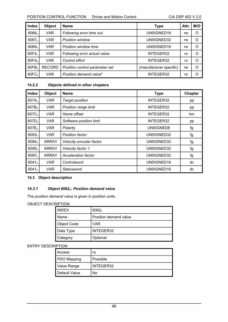
POSITION CONTROL FUNCTION Drives and Motion Control CiA DSP 402 V 2.0
98
Index Object Name Type Attr. M/O
6066h VAR Following error time out UNSIGNED16 rw O
6067h VAR Position window UNSIGNED32 rw O
6068h VAR Position window time UNSIGNED16 rw O
60F4h VAR Following error actual value INTEGER32 ro O
60FAh VAR Control effort INTEGER32 ro O
60FBh RECORD Position control parameter set (manufacturer specific) rw O
60FCh VAR Position demand value* INTEGER32 ro O
14.2.2 Objects defined in other chapters
Index Object Name Type Chapter
607Ah VAR Target position INTEGER32 pp
607Bh VAR Position range limit INTEGER32 pp
607Ch VAR Home offset INTEGER32 hm
607Dh VAR Software position limit INTEGER32 pp
607Eh VAR Polarity UNSIGNED8 fg
6093h VAR Position factor UNSIGNED32 fg
6094h ARRAY Velocity encoder factor UNSIGNED32 fg
6095h ARRAY Velocity factor 1 UNSIGNED32 fg
6097h ARRAY Acceleration factor UNSIGNED32 fg
6041h VAR Controlword UNSIGNED16 dc
6041h VAR Statusword UNSIGNED16 dc
14.3 Object description
14.3.1 Object 6062h: Position demand value
The position demand value is given in position units.
OBJECT DESCRIPTION
INDEX 6062h
Name Position demand value
Object Code VAR
Data Type INTEGER32
Category Optional
ENTRY DESCRIPTION
Access ro
PDO Mapping Possible
Value Range INTEGER32
Default Value No

POSITION CONTROL FUNCTION Drives and Motion Control CiA DSP 402 V 2.0
99
14.3.2 Object 6063h: Position actual value*
The actual value of the position measurement device is one of the two input values of the closed loopposition control. The data unit is defined as increments. If necessary, the data unit must betransformed with the position factor defined in chapter 11 from user defined units to increments.
OBJECT DESCRIPTION
INDEX 6063h
Name Position actual value*
Object Code VAR
Data Type INTEGER32
Category Optional
ENTRY DESCRIPTION
Access ro
PDO Mapping Possible
Value Range INTEGER32
Default Value No
14.3.3 Object 6064h: Position actual value
This object represents the actual value of the position measurement device in user defined units.
OBJECT DESCRIPTION
INDEX 6064h
Name Position actual value
Object Code VAR
Data Type INTEGER32
Category Conditional;
Mandatory, if pc supported
Optional, if pp, ip, hm or tq supported
ENTRY DESCRIPTION
Access ro
PDO Mapping Possible
Value Range INTEGER32
Default Value No
14.3.4 Object 6065h: Following error window
The following error window defines a range of tolerated position values symmetrically to the positiondemand value. As it is in most cases used with user defined units, a transformation into incrementswith the position factor is necessary. If the position actual value is out of the following error window, afollowing error occurs
A following error might occur when
• a drive is blocked,
• unreachable profile velocity occurs, or
• at wrong closed loop coefficients.
If the value of the following error window is 232-1, the following control is switched off.

POSITION CONTROL FUNCTION Drives and Motion Control CiA DSP 402 V 2.0
100
OBJECT DESCRIPTION
INDEX 6065h
Name Following error window
Object Code VAR
Data Type UNSIGNED32
Category Optional
ENTRY DESCRIPTION
Access rw
PDO Mapping Possible
Value Range UNSIGNED32
Default Value No
14.3.5 Object 6066h: Following error time out
When a following error occurs longer than the defined value of the time-out given in multiples ofmilliseconds, the corresponding bit 13 following error in the statusword will be set to one. The reactionof the drive when a following error occurs, is manufacturer specific.
OBJECT DESCRIPTION
INDEX 6066h
Name Following error time out
Object Code VAR
Data Type UNSIGNED16
Category Optional
ENTRY DESCRIPTION
Access rw
PDO Mapping Possible
Value Range UNSIGNED16
Default Value No
14.3.6 Object 6067h: Position window
The position window defines a symmetrical range of accepted positions relatively to the target position.If the actual value of the position encoder is within the position window, this target position is regardedas reached. As the user mostly prefers to specify the position window in his application in user definedunits, the position factor of chapter 11 must be used to transform this value into increments. The targetposition has to be handled in the same manner as in the Trajectory Generator concerning limitingfunctions and transformation into internal machine units before it can be used with this function.
If the value of the position window is 232-1, the position window control is switched off.
OBJECT DESCRIPTION
INDEX 6067h
Name Position window
Object Code VAR
Data Type UNSIGNED32
Category Optional

POSITION CONTROL FUNCTION Drives and Motion Control CiA DSP 402 V 2.0
101
ENTRY DESCRIPTION
Access rw
PDO Mapping Possible
Value Range UNSIGNED32
Default Value No
14.3.7 Object 6068h : Position window time
When the actual position is within the position window during the defined position window time whichis given in multiples of milliseconds, the corresponding bit 10 target reached in the statusword will beset to one.
OBJECT DESCRIPTION
INDEX 6068h
Name Position window time
Object Code VAR
Data Type UNSIGNED16
Category Optional
ENTRY DESCRIPTION
Access rw
PDO Mapping Possible
Value Range UNSIGNED16
Default Value No
14.3.8 Object 60F4h: Following error actual value
This object represents the actual value of the following error, it is given in user defined position units.
OBJECT DESCRIPTION
INDEX 60F4h
Name Following error actual value
Object Code VAR
Data Type INTEGER32
Category Optional
ENTRY DESCRIPTION
Access ro
PDO Mapping Possible
Value Range INTEGER32
Default Value No

POSITION CONTROL FUNCTION Drives and Motion Control CiA DSP 402 V 2.0
102
14.3.9 Object 60FAh: Control effort
The output of the position control loop is the control effort. It is particular to the Position controlfunction that the notation of the control effort is mode dependent and therefore not specified in theobject description.
OBJECT DESCRIPTION
INDEX 60FAh
Name Control effort
Object Code VAR
Data Type INTEGER32
Category Optional
ENTRY DESCRIPTION
Access ro
PDO Mapping Possible
Value Range INTEGER32
Default Value No
14.3.10 Object 60FBh: Position control parameter set
In order to control the behavior of the position control loop one or more parameters are necessary.This object is a means to define control parameters which are highly manufacturer specific. For thisreason, these parameters shall not be described in this document at all.
OBJECT DESCRIPTION
INDEX 60FBh
Name Position control parameter set
Object Code RECORD
Data Type manufacturer specific
Category Optional
ENTRY DESCRIPTION
Sub-Index 0
Description number of entries
Entry Category Mandatory
Access ro
PDO Mapping No
Value Range 1 .. 254
Default Value No

POSITION CONTROL FUNCTION Drives and Motion Control CiA DSP 402 V 2.0
103
Sub-Index 1
Description manufacturer specific
Entry Category Mandatory
Access rw
PDO Mapping Possible
Value Range manufacturer specific
Default Value No
Sub-Index 2
Description manufacturer specific
Entry Category Optional
Access rw
PDO Mapping Possible
Value Range manufacturer specific
Default Value No
to
Sub-Index 254
Description manufacturer specific
Entry Category Optional
Access rw
PDO Mapping Possible
Value Range manufacturer specific
Default Value No
14.3.11 Object 60FCh: Position demand value*
This output of the trajectory generator in profile position mode is an internal value using increments asunit what is expressed with an *. To save calculation time for some applications, this object isadditionally introduced to the position demand value (6062h).
OBJECT DESCRIPTION
INDEX 60FCh
Name Position demand value*
Object Code VAR
Data Type INTEGER32
Category Optional
ENTRY DESCRIPTION
Access ro
PDO Mapping Possible
Value Range INTEGER32
Default Value No

POSITION CONTROL FUNCTION Drives and Motion Control CiA DSP 402 V 2.0
104
14.4 Functional description
Figure 33 shows the meaning of the sub-function position reached. Symmetrically around the targetposition a window is defined for the accepted position range. If a drive is situated in the acceptedposition range over the time position window time the bit target reached (bit 10) in the statusword is toset.
Figure 33: Position reached
Figure 34 shows the meaning of the sub-function following error in the profile position mode.Symmetrically around the reference position a window is defined for the accepted following errortolerance. If a drive is situated out of the accepted position range for more than following error time outtime the bit following error (bit 13) in the statusword is set.
Figure 34: Following error
accepted position range
position not reached position reached
position window
target position
position
position window
position not reached
accepted followingerror tolerance
reference position
following error no following error
followingerror
window
positionfollowingerror
window
following error

INTERPOLATED POSITION MODE Drives and Motion Control CiA DSP 402 V 2.0
105
15 INTERPOLATED POSITION MODE
15.1 General information
The interpolated position mode is used to control multiple coordinated axles or a single axle with theneed for time-interpolation of set-point data. The interpolated position mode normally uses timesynchronization mechanisms like the sync object defined in /3/ for a time coordination of the relateddrive units.
The interpolation data record contains the interpolation data; the data type of the sub-indices of thisstructure manufacturer specific. Only the record size is fixed in the size of data record as sub-index ofthe interpolation data configuration
For synchronous operation the interpolation cycle time is defined by the object interpolation timeperiod. For asynchronous operation the interpolation time period for each time slice must be includedin the interpolation data record.
Time synchronization can be done by the Sync message (see /3/), a specific group sync signal (broad-cast) or in specified time slices which are activated with the start signal.
The interpolated position mode allows a host controller to transmit a stream of interpolation data witheither an implicit or explicit time reference to a drive unit. If the drive supports an input buffer, theinterpolation data may be sent in bursts rather than continuously in real time. The actually availableand the maximum size of the input buffer can be requested by a host using the interpolation dataconfiguration. The buffer size is the number of interpolation data records which may be sent to a driveto fill the input buffer and it is not the size in bytes. Devices without input buffer capabilities have toaccept at least one interpolation data item.
The interpolation algorithm is defined in the interpolation sub mode select. Linear interpolation is thedefault interpolation method. This requires only one interpolation data item to be buffered for thecalculation of the next demand value. For each interpolation cycle, the drive will calculate a positiondemand value by interpolating positions over a period of time.
Optionally the common limit functions for speed, acceleration and deceleration may be applied to theinterpolation data.

INTERPOLATED POSITION MODE Drives and Motion Control CiA DSP 402 V 2.0
106
LimitFunction
position_range_limit (607Bh)software_position_limit (607Dh)home_offset (607Ch)
InterpolationFunction
Input Bufferinterpolation_data_record(60C1h)
interpolation_data_configuration(60C4h)
interpolation_submode_select(60C0h)
Limit Function
profile_acceleration(6083h) [acceleration units]
quick_stop_deceleration(6085h)
[acceleration units]
max_acceleration (60C5h)max_deceleration (60C6h)
profile_deceleration(6084h)
[acceleration units]
Limit Function
profile_velocity(6081h) [speed units]
velocity limit
end_velocity(6082h)
[speed units]
MinimumComparator
[speed units]
Multiplier
velocity_factor_1(6095h)
max_profile_velocity(607Fh)
max_motor_speed(6080h)
position
velocity
acceleration

INTERPOLATED POSITION MODE Drives and Motion Control CiA DSP 402 V 2.0
107
Multiplier
position_factor (6093h)polarity (607Eh)
[inc]
Multiplier
acceleration_factor (6097h)
[inc/s2]
Multiplier
velocity_encoder_factor (6094h)polarity (607Eh)
[inc/s]
quick_stop_option_code(605Ah)
position_demand_value*(60FCh)
[ inc]
InterpolationController
ProfileVelocity*End Velocity*
Profile Acceleration*ProfileDeceleration*Quick StopDeceleration*
Quick Stop OptionCode
InterpolatedPosition*
acceleration
velocity
position
Figure 35: Interpolation controller
15.1.1 Input data description
Operating mode Input parameters used
ip interpolation sub mode select, max profile velocity, profile acceleration,profile deceleration, quick stop deceleration*, quick stop mode
15.1.2 Output data description
The output values provided by the Interpolated position mode depend on the number and type ofinterpolation functions implemented by a manufacturer. For the predefined linear time interpolation theoutput is a position demand value*.
Operation mode Output parameter used
ip position demand value*

INTERPOLATED POSITION MODE Drives and Motion Control CiA DSP 402 V 2.0
108
15.1.3 Internal states
15.1.3.1 State description
Operation enabled1)
Interpolation inactive
Interpolated PositionMode selected
(1)
quickstop1)
changing the Modeof Operation or
deselect InterpolatedPosition Mode
(2)
disable voltage1)
shutdown1)
Interpolation active
enableInterpolation
(3)
disableInterpolation
(4)
1)see state machine
Figure 36: Internal states for the Interpolated position mode
• Interpolation inactiveThis state is entered when the device is in state OPERATION ENABLE and theInterpolated position mode is selected. The drive unit will accept input data and will bufferit for interpolation calculations, but it does not move the axles.
• Interpolation activeThis state is entered when the device is in state OPERATIION ENABLE, the Interpolatedposition mode is selected and enabled. The drive unit will accept input data and it movesthe axles.
15.1.3.2 State transitions of the internal states
• State Transition 1: NO IP-MODE SELECTED => IP-MODE INACTIVEEvent: Enter in the state OPERATION ENABLE with controlword and select ip
mode with modes of operation
• State Transition 2: IP-MODE INACTIVE => NO IP-MODE SELECTEDEvent: Leave the state OPERATION ENABLE with controlword or select any
other mode with modes of operation if it is allowed inside the state OPERATION ENABLE
• State Transition 3: IP-MODE INACTIVE => IP-MODE ACTIVEEvent: Set bit enable ip mode (bit4) of the controlword while in ip mode and
OPERATION ENABLE
• State Transition 4: IP-MODE ACTIVE => IP-MODE INACTIVEEvent: Reset bit enable ip mode (bit4) of the controlword while in ip mode and
OPERATION ENABLE

INTERPOLATED POSITION MODE Drives and Motion Control CiA DSP 402 V 2.0
109
15.1.3.3 Controlword of interpolated position mode
15 9 8 7 6 5 4 3 0
(see 10.3.1) Halt (see 10.3.1) reserved Enable ip mode (see 10.3.1)
MSB LSB
Name Value Description
0 Interpolated position mode inactiveEnable ipmode
1 Interpolated position mode active
0 Execute the instruction of bit 4Halt
1 Stop axle
Table 13: Interpolated position mode bits of the controlword
15.1.3.4 Statusword of interpolated position mode
15 14 13 12 11 10 9 0
(see 10.3.2) reserved ip modeactive
(see 10.3.2) Targetreached
(see 10.3.2)
MSB LSB
Name Value Description
0 Halt = 0: Position not (yet) reached
Halt = 1: Axle decelerates
Targetreached
1 Halt = 0: Position reached
Halt = 1: Axle has velocity 0
0 Interpolated position mode inactiveip modeactive
1 Interpolated position mode active
Table 14: Interpolated position mode bits of the statusword
15.2 Complex data types
15.2.1 Interpolation time period record
Index Sub Field in interpolation time period record Data type
0 number of entries UNSIGNED8
1 Interpolation time units UNSIGNED8
0080h
2 Interpolation time index INTEGER8

INTERPOLATED POSITION MODE Drives and Motion Control CiA DSP 402 V 2.0
110
15.2.2 Interpolation data configuration record
15.3 Object dictionary entries
15.3.1 Objects defined in this chapter
Index Object Name Type Attr. M/O
60C0h VAR Interpolation sub mode select INTEGER16 rw O
60C1h ARRAY Interpolation data record INTEGER32 rw O
60C2h RECORD Interpolation time period Interpolation timeperiod record
rw O
60C3h ARRAY Interpolation sync definition UNSIGNED8 rw O
60C4h RECORD Interpolation data configuration Interpolation dataconfiguration record
rw O
15.3.2 Objects defined in other chapters
Index Object Name Type Chapter
6040h VAR Controlword UNSIGNED16 dc
6041h VAR Statusword UNSIGNED16 dc
605Ah VAR Quick stop option mode INTEGER16 dc
6060h VAR Modes of operation INTEGER8 dc
6061h VAR Modes of operation display INTEGER8 dc
6062h VAR Position demand value INTEGER32 pc
6063h VAR Position actual value* INTEGER32 pc
606Ah VAR Sensor selection code UNSIGNED8 pv
607Fh VAR Max profile velocity UNSIGNED32 pp
6089h VAR Position notation index INTEGER8 fg
608Ah VAR Position dimension index UNSIGNED8 fg
608Bh VAR Velocity notation index INTEGER8 fg
608Ch VAR Velocity dimension index UNSIGNED8 fg
608Dh VAR Acceleration notation index INTEGER8 fg
608Eh VAR Acceleration dimension index UNSIGNED8 fg
608Fh ARRAY Position encoder resolution UNSIGNED32 fg
6090h ARRAY Velocity encoder resolution UNSIGNED32 fg
Index Sub Field in interpolation time period record Data type
0 number of entries UNSIGNED8
1 Maximum buffer size UNSIGNED32
2 Actual buffer size UNSIGNED32
3 Buffer organization UNSIGNED8
4 Buffer position UNSIGNED16
5 Size of data record UNSIGNED8
0081h
6 Buffer clear UNSIGNED8
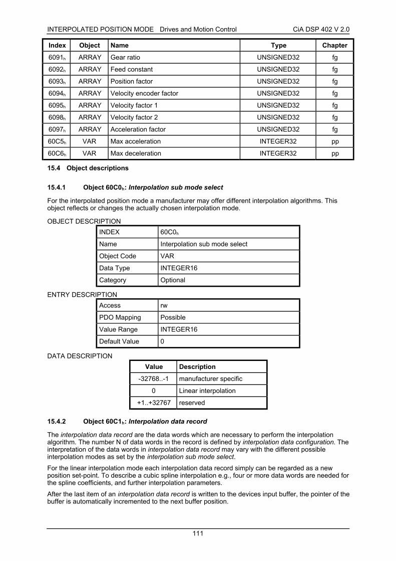
INTERPOLATED POSITION MODE Drives and Motion Control CiA DSP 402 V 2.0
111
Index Object Name Type Chapter
6091h ARRAY Gear ratio UNSIGNED32 fg
6092h ARRAY Feed constant UNSIGNED32 fg
6093h ARRAY Position factor UNSIGNED32 fg
6094h ARRAY Velocity encoder factor UNSIGNED32 fg
6095h ARRAY Velocity factor 1 UNSIGNED32 fg
6098h ARRAY Velocity factor 2 UNSIGNED32 fg
6097h ARRAY Acceleration factor UNSIGNED32 fg
60C5h VAR Max acceleration INTEGER32 pp
60C6h VAR Max deceleration INTEGER32 pp
15.4 Object descriptions
15.4.1 Object 60C0h: Interpolation sub mode select
For the interpolated position mode a manufacturer may offer different interpolation algorithms. Thisobject reflects or changes the actually chosen interpolation mode.
OBJECT DESCRIPTION
INDEX 60C0h
Name Interpolation sub mode select
Object Code VAR
Data Type INTEGER16
Category Optional
ENTRY DESCRIPTION
Access rw
PDO Mapping Possible
Value Range INTEGER16
Default Value 0
DATA DESCRIPTION
Value Description
-32768..-1 manufacturer specific
0 Linear interpolation
+1..+32767 reserved
15.4.2 Object 60C1h: Interpolation data record
The interpolation data record are the data words which are necessary to perform the interpolationalgorithm. The number N of data words in the record is defined by interpolation data configuration. Theinterpretation of the data words in interpolation data record may vary with the different possibleinterpolation modes as set by the interpolation sub mode select.
For the linear interpolation mode each interpolation data record simply can be regarded as a newposition set-point. To describe a cubic spline interpolation e.g., four or more data words are needed forthe spline coefficients, and further interpolation parameters.
After the last item of an interpolation data record is written to the devices input buffer, the pointer of thebuffer is automatically incremented to the next buffer position.

INTERPOLATED POSITION MODE Drives and Motion Control CiA DSP 402 V 2.0
112
OBJECT DESCRIPTION
INDEX 60C1h
Name Interpolation data record
Object Code ARRAY
Data Type 60C0h < 0 : manufacturer specific
60C0h = 0 : INTEGER32
60C0h > 0 : not defined
Category Optional
ENTRY DESCRIPTION
Sub-Index 0
Description number of entries
Entry Category Mandatory
Access ro
PDO Mapping No
Value Range 1 .. N
Default Value No
Sub-Index 1
Description x1
the first parameter of ip function fip(x1, .. xN)
Entry Category Mandatory
Access rw
PDO Mapping Possible
Value Range 60C0h < 0 : manufacturer specific
60C0h = 0 : INTEGER32
60C0h > 0 : not defined
Default Value No
Sub-Index 2
Description x2
the second parameter of ip function fip(x1, .. xN)
Entry Category Optional
Access rw
PDO Mapping Possible
Value Range 60C0h < 0 : manufacturer specific
60C0h = 0 : INTEGER32
60C0h > 0 : not defined
Default Value No
to

INTERPOLATED POSITION MODE Drives and Motion Control CiA DSP 402 V 2.0
113
Sub-Index N
Description xN
the N-th parameter of ip function fip(x1, .. xN)
Entry Category Optional
Access rw
PDO Mapping Possible
Value Range 60C0h < 0 : manufacturer specific
60C0h = 0 : INTEGER32
60C0h > 0 : not defined
Default Value No
15.4.3 Object 60C2h: Interpolation time period
The interpolation time period is used for time synchronized interpolation position modes. The unit ofthe interpolation time unit is given in 10interpolation time index seconds.
OBJECT DESCRIPTION
INDEX 60C2h
Name Interpolation time period
Object Code RECORD
Data Type Interpolation time period record (0080h)
Category Optional
ENTRY DESCRIPTION
Sub-Index 0
Description number of entries
Entry Category Mandatory
Access ro
PDO Mapping No
Value Range 2
Default Value 2
Sub-Index 1
Description Interpolation time units
Entry Category Mandatory
Access rw
PDO Mapping Possible
Value Range UNSIGNED8
Default Value 1

INTERPOLATED POSITION MODE Drives and Motion Control CiA DSP 402 V 2.0
114
Sub-Index 2
Description Interpolation time index
Entry Category Mandatory
Access rw
PDO Mapping Possible
Value Range -128 .. 63
Default Value -3
15.4.4 Object 60C3h: Interpolation sync definition
Devices in the interpolation position mode often interact with other devices. Therefore it is necessaryto define a communication object which is used to synchronize these interactions.
This can be done by the general Sync as described in /3/, or a specific group-sync-signal. Eachreception of this trigger-signal or a specified number of occurrences of the trigger-signal cansynchronize the devices; a second opportunity is to use fixed time slices for synchronization.
Value Description
0 General Sync is used
1 .. 255 reserved
Table 15: Description of synchronize on group
OBJECT DESCRIPTION
INDEX 60C3h
Name Interpolation sync definition
Object Code ARRAY
Data Type UNSIGNED8
Category Optional
ENTRY DESCRIPTION
Sub-Index 0
Description number of entries
Entry Category Mandatory
Access ro
PDO Mapping No
Value Range 2
Default Value 2
Sub-Index 1
Description Synchronize on group
Entry Category Mandatory
Access rw
PDO Mapping Possible
Value Range UNSIGNED8
Default Value 0

INTERPOLATED POSITION MODE Drives and Motion Control CiA DSP 402 V 2.0
115
Sub-Index 2
Description ip sync every n event
Entry Category Mandatory
Access rw
PDO Mapping Possible
Value Range UNSIGNED8
Default Value 1
15.4.5 Object 60C4h: Interpolation data configuration
It is possible to offer different algorithms of interpolation. Most of them need a larger number ofposition to calculate the actual position the axles should reach. To enable the device to receive theneeded data in advance a data space is used to store the positions and further data send by the host.
Value Description
0 FIFO buffer
1 Ring buffer
2 .. 255 reserved
Table 16: Types of buffer organization
Value Description
0 • Clear input buffer
• Access disabled
• Clear all ip data records
1 Enable access to the input buffer for the drive functions
2 .. 255 reserved
Table 17: Description of buffer clear values
OBJECT DESCRIPTION
INDEX 60C4h
Name Interpolation data configuration
Object Code RECORD
Data Type Interpolation data configuration record (0081h)
Category Optional
ENTRY DESCRIPTION
Sub-Index 0
Description number of entries
Entry Category Mandatory
Access ro
PDO Mapping No
Value Range 6
Default Value 6

INTERPOLATED POSITION MODE Drives and Motion Control CiA DSP 402 V 2.0
116
Sub-Index 1
Description Maximum buffer size
Entry Category Mandatory
Access ro
PDO Mapping No
Value Range UNSIGNED32
Default Value 1
Sub-Index 2
Description Actual buffer size
Entry Category Mandatory
Access rw
PDO Mapping Possible
Value Range UNSIGNED32
Default Value 0
Sub-Index 3
Description Buffer organization
Entry Category Mandatory
Access rw
PDO Mapping Possible
Value Range UNSIGNED8
Default Value 0
Sub-Index 4
Description Buffer position
Entry Category Mandatory
Access rw
PDO Mapping Possible
Value Range UNSIGNED16
Default Value 0
Sub-Index 5
Description Size of data record
Entry Category Mandatory
Access wo
PDO Mapping Possible
Value Range 1 .. 254
Default Value 1

INTERPOLATED POSITION MODE Drives and Motion Control CiA DSP 402 V 2.0
117
Sub-Index 6
Description Buffer clear
Entry Category Mandatory
Access wo
PDO Mapping Possible
Value Range UNSIGNED8
Default Value 0
15.5 Functional description
15.5.1 Interpolated position mode
A drive can be controlled and supervised by the controlword and the statusword respectively. Tochoose the operation mode, the modes of operation is used. The activated operation mode ismonitored by modes of operation display.
A drive manufacturer has to specify the way the device handles a just received interpolation datarecord. This can be in a way corresponding to the standard position mode, or might be a morecomplex algorithm. The standard method is to apply new data immediately, respectively after the nextsynchronization signal.
An input buffer for interpolation data records is not mandatory, although it eases the data exchangebetween a host and a drive unit. The real-time requirements to the CAN-bus as well as to the drive unitdecrease in this case, because an input buffer decouples the data processing in the drive from thedata transmission via the bus line.
15.5.2 Linear interpolated position mode with several axles
In order to follow a two- or more-dimensional curve through the space with a defined speed, a host (aninterpolation controller or a PLC) calculates the different positions Pi for each set of coordinates whichhave to be reached at specified times ti.
To use the interpolation mode with several axles the host calculates the next or more positions andtimestamps, and transmits them to the different axles. For each set-point Pi the interpolation controllerhas to calculate xi, yi... and ti. Each axle gets a set of interpolation data records which each axle has toprocess internally independent from the other axles according to the chosen interpolation mode.
X
Y vPi = (xi, yi,ti)
Pi+1 = (xi+1, yi+1,ti+1)
∆s(x,y)
Figure 37: Interpolation for two axles

INTERPOLATED POSITION MODE Drives and Motion Control CiA DSP 402 V 2.0
118
In a centralized drive system with a remote motion device doing the interpolation calculation, a centralclocking scheme for synchronization of the different axles based on any kind of sync-signal is used.This results in a movement depending on the calculation cycle time of the interpolation controller. Thevelocity becomes more or less a fixed value for each axle.
ip data records forcalculatedpositions x-axle y-axle z-axle
Pi xi , ti yi , ti zi , ti
Pi+1 xi+1 , ti+1 yi+1 , ti+1 zi+1 , ti+1
Pi+2 xi+2 , ti+2 yi+2 , ti+2 zi+2 , ti+2
Pi+3 xi+3 , ti+3 yi+3 , ti+3 zi+3 , ti+3
• • • •
• • • •
• • • •
Pi+n xi+n , ti+n yi+n , ti+n zi+n , ti+n
Table 18: Position calculation in interpolated position mode for several axles
In decentralized motion systems a host starts all relevant axles by changing the mode-internal state tointerpolation active after preparing and sending one or more interpolation data records to all axles andsynchronizes them by a (group) sync-signal. Each axle calculates internally and independently thenecessary speed and acceleration needed to move from one position to the next. This can be done bycalculating a linear or any other move between two given position set-points. Along this track everyaxle controls the movement between the set-points independently from the other axles. The axles maycontinue their move, as long as there is enough data to continue the calculations. Therefore it is easyto use the input buffer to give data records ahead.
With this information each axle can act like it is shown in Figure 37.
Position
Timeti ti+1 ti+2ti-1
tsync
position loopsample period
given interpolation position
calculated position
Pi-1
Pi
Pi+1
Pi+2Pi+3
ti+3
Figure 38: Linear interpolation for one axle
15.5.3 Buffer strategies for the interpolated position mode
If a device provides an input buffer for interpolation data records its size can be organized by a hostusing the interpolation data configuration. The host splits the available buffer capacity into pageswhich have the size of one interpolation data record each. This is done by size of data record. If one

INTERPOLATED POSITION MODE Drives and Motion Control CiA DSP 402 V 2.0
119
page remains, which can not keep one complete data record, it can not be used. After thereorganization of the input buffer all previous stored data will be lost. All devices supporting theinterpolated position mode need to implement an input buffer, which at least can keep oneinterpolation data record.
The content of the buffer items can only be accessed via the interpolation data record.
Commonly, first-in-first-out (FIFO) structures or ring buffers are used as input buffers.
• FIFO:If the buffer is organized as FIFO, every new received interpolation data record is placed atthe end of the queue, and the device takes the next data record from the top of the queue.When the last item of a data record is stored, the buffer pointer is incremented in order to pointto the next buffer position. For this buffer principle the object buffer position does not have anyinfluence.
• Ring buffer:If the buffer is structured as a ring, the host can place an interpolation data record into anyvalid position in the ring by changing the pointer defined in buffer position. Without changingthe buffer position all data records will be written at the same location. The drive reads thenext entry out of the buffer by an internal ring pointer. It is set to the first data record withbuffer clear, and after the reorganization of the input buffer.
↑ parameter 1 ↑
parameter 2data record size
:::::
↓ parameter n
ip data record 1
↑ parameter 1
parameter 2data record size
:::::
↓ parameter n
ip data record 2
:::::
↑ parameter 1
parameter 2data record size
:::::
↓ parameter n
ip data record i
buffer size
not accessible ↓
Figure 39: Input buffer organization

PROFILE VELOCITY MODE Drives and Motion Control CiA DSP 402 V 2.0
120
16 PROFILE VELOCITY MODE
16.1 General Information
The profile velocity mode includes the following sub-functions:
• demand value input via trajectory generator
• velocity capture using position sensor or velocity sensor
• velocity control function with appropriate input and output signals
• limitation of torque demand value
• monitoring of the profile velocity using a window-function
• monitoring of velocity actual value using a threshold
The operation of the reference value generator and its input parameters:
• profile velocity,
• profile acceleration,
• profile deceleration,
• emergency stop, and
• motion profile type
are described in the profile position mode (see 12).
Various sensors can be used for velocity capture. In particular the aim is that costs should be reducedand the system should be simplified by evaluating position and velocity using a common sensor, suchas is possible using a resolver or an encoder.
The velocity control function is not specified more precisely at this point as it is highly manufacturerspecific, but the format and maximum number of control coefficients are established.
The velocity controller calculates a torque variable. This is added to a torque pre-control calculated bythe trajectory generator and limited to a torque max value. The limited total is used as input to thetorque controller as a torque demand value.
Monitoring functions for the velocity actual value provide status information for super-ordinatedsystems.

PROFILE VELOCITY MODE Drives and Motion Control CiA DSP 402 V 2.0
121
velocitylimit
target_velocity(60FFh)
[velocity units]
MinimumComparator
[velocity units]
Multiplier
velocity_factor_1(6095h)
max_profile_velocity(607Fh)
max_motor_speed(6080h)
Limit Function
profile_acceleration(6083h)
[acceleration units]
quick_stop_deceleration(6085h)
[acceleration units]
max_acceleration(60C5h)max_deceleration(60C6h)
profile_deceleration(6084h)
[acceleration units]
Multiplier
velocity_encoder_factor(6094h)
Multiplier
motion_profile_type(6086h)
Motion ProfileType
ProfileVelocity*
ProfileAcceleration*ProfileDeceleration*Quick StopDeceleration*
velocity demand*
polarity(607Eh)
Multiplier Multiplier
velocity_factor_1(6095h)
[velocity units G2]
velocity_demand_value(606Bh)
velocity demand*

PROFILE VELOCITY MODE Drives and Motion Control CiA DSP 402 V 2.0
122
VelocityController
control effort
VelocitySensor
Selection
velocity[inc/s]
Multiplier
velocity_factor_2(6096h)
velocity_sensor_actual_value(6069h)
position_actual_value*(6063h)
Differentiationd/dt
sensor_selection_code(606Ah)
velocity_control_parameter_set(60F9h)
Multiplier
velocity_factor_1(6095h)
polarity (607Eh)
[velocity units G2]Multipliervelocity_actual_value(606Ch)
WindowComparator Timer
status_word(6041h)
velocity_reached
Multiplier
velocity_factor_1(6095h)
velocity_window(606Dh)
velocity_window_time(606Eh)
control effort
WindowComparator
Timer
status_word(6041h)
velocity=0
Multiplier
velocity_factor_1(6095h)
velocity_threshold(606Fh)
velocity_threshold_time(6070h)
control effort
Comparator
slippage>max_slippage
Multiplier
velocity_factor_1(6095h)
max_slippage(60F9h)
control effort
status_word(6041h)
velocity_demand_value(606Bh)
velocity demand
Figure 40: Structure of the profile velocity mode

PROFILE VELOCITY MODE Drives and Motion Control CiA DSP 402 V 2.0
123
16.1.1 Input data description
Operating mode Input parameters used
pv target velocity, velocity factor 1, velocity factor 2, velocity window,velocity window time, velocity threshold, velocity threshold time, maxslippage, profile acceleration, profile deceleration, quick stopdeceleration, max acceleration, max deceleration, polarity, quick stopoption code, motion profile type, max profile velocity, max motor speed
16.1.2 Output data description
Operation mode Output parameter used
pv velocity actual value, velocity demand value, statusword
16.1.3 Internal states
The profile velocity mode has to be controlled by the bits of the controlword and statusword.
16.1.3.1 Controlword of profile velocity mode
15 9 8 7 6 4 3 0
(see 10.3.1) Halt (see 10.3.1) reserved (see 10.3.1)
MSB LSB
Name Value Description
0 Execute the motionHalt
1 Stop axle
Table 19: Profile velocity mode bits of the controlword
16.1.3.2 Statusword of profile velocity mode
15 14 13 12 11 10 9 0
(see 10.3.2) Max slippageerror
Speed (see 10.3.2) Targetreached
(see 10.3.2)
MSB LSB
Name Value Description
0 Halt = 0: Target velocity not (yet) reached
Halt = 1: Axle decelerates
Targetreached
1 Halt = 0: Target velocity reached
Halt = 1: Axle has velocity 0
0 Speed is not equal 0Speed
1 Speed is equal 0
0 Maximum slippage not reachedMaxslippage
error 1 Maximum slippage reached
Table 20: Profile velocity mode bits of the statusword

PROFILE VELOCITY MODE Drives and Motion Control CiA DSP 402 V 2.0
124
16.2 Object dictionary entries
16.2.1 Objects defined in this chapter
Index Object Name Type Attr. M/O
6069h VAR Velocity sensor actual value INTEGER32 ro M
606Ah VAR Sensor selection code INTEGER16 rw O
606Bh VAR Velocity demand value INTEGER32 ro M
606Ch VAR Velocity actual value INTEGER32 ro M
606Dh VAR Velocity window UNSIGNED16 rw O
606Eh VAR Velocity window time UNSIGNED16 rw O
606Fh VAR Velocity threshold UNSIGNED16 rw O
6070h VAR Velocity threshold time UNSIGNED16 rw O
60FFh VAR Target velocity INTEGER32 rw M
60F8h VAR Max slippage INTEGER32 rw O
60F9h ARRAY Velocity control parameter set UNSIGNED16 rw O
16.2.2 Objects defined in other chapters
Index Object Name Type Chapter
6040h VAR Controlword UNSIGNED16 dc
6041h VAR Statusword UNSIGNED16 dc
6063h VAR Position actual value* INTEGER32 pc
6069h VAR Velocity sensor actual value INTEGER32 pv
6071h VAR Target torque INTEGER16 tq
6072h VAR Max torque UNSIGNED16 tq
607Eh VAR Polarity UNSIGNED8 fg
607Fh VAR Max profile velocity UNSIGNED32 pp
6080h VAR Max motor speed UNSIGNED32 pp
6083h VAR Profile acceleration UNSIGNED32 pp
6084h VAR Profile deceleration UNSIGNED32 pp
6085h VAR Quick stop deceleration UNSIGNED32 pp
6086h VAR Motion profile type INTEGER16 pp
6094h ARRAY Velocity encoder factor UNSIGNED32 fg
6095h ARRAY Velocity factor 1 UNSIGNED32 fg
6096h ARRAY Velocity factor 2 UNSIGNED32 fg
16.3 Object description
The factors necessary for scaling• velocity reference factor,• velocity factor 1, and• velocity factor 2
have a linear relationship and therefore they are described in the factor group. The polarity isdescribed in the factor group as well.

PROFILE VELOCITY MODE Drives and Motion Control CiA DSP 402 V 2.0
125
16.3.1 Object 6069h: Velocity sensor actual value
The velocity sensor actual value describes the value read from a velocity encoder (if present) inincrements (in the case of encoders) and in increments per second (in the case of tachometers andAD converters). This value is scaled to the format of the position encoder using the scaling factorvelocity factor 2.
OBJECT DESCRIPTION
INDEX 6069h
Name Velocity sensor actual value
Object Code VAR
Data Type INTEGER32
Category Conditional;
Mandatory, if pv supported
ENTRY DESCRIPTION
Access ro
PDO Mapping Possible
Value Range INTEGER32
Default Value No
16.3.2 Object 606Ah: Sensor selection code
The source of the velocity sensor actual value can be determined using the sensor selection code.This determines whether a differentiated position signal or the signal from a separate velocity sensorhas to be evaluated.
OBJECT DESCRIPTION
INDEX 606Ah
Name Sensor selection code
Object Code VAR
Data Type INTEGER16
Category Optional
ENTRY DESCRIPTION
Access rw
PDO Mapping Possible
Value Range INTEGER16
Default Value No
DATA DESCRIPTION
Value Description
0000h Actual velocity value from position encoder
0001h Actual velocity value from velocity encoder
0002h .. 7FFFh reserved
8000h ... FFFFh manufacturer specific

PROFILE VELOCITY MODE Drives and Motion Control CiA DSP 402 V 2.0
126
16.3.3 Object 606Bh: Velocity demand value
The output value of the trajectory generator may be corrected by the output value of the positioncontrol function. It is then provided as a demand value for the velocity controller and given in thevelocity units.
OBJECT DESCRIPTION
INDEX 606Bh
Name Velocity demand value
Object Code VAR
Data Type INTEGER32
Category Conditional;
Mandatory, if pv supported
ENTRY DESCRIPTION
Access ro
PDO Mapping Possible
Value Range INTEGER32
Default Value No
16.3.4 Object 606Ch: Velocity actual value
The velocity actual value is also represented in velocity units and is coupled to the velocity used asinput to the velocity controller.
OBJECT DESCRIPTION
INDEX 606Ch
Name Velocity actual value
Object Code VAR
Data Type INTEGER32
Category Conditional;
Mandatory, if pv supported
ENTRY DESCRIPTION
Access ro
PDO Mapping Possible
Value Range INTEGER32
Default Value No
16.3.5 Object 606Dh: Velocity window
The velocity window monitors whether the required process velocity has been achieved after aneventual acceleration or deceleration (braking) phase. It is given in velocity units.
OBJECT DESCRIPTION
INDEX 606Dh
Name Velocity window
Object Code VAR
Data Type UNSIGNED16
Category Optional

PROFILE VELOCITY MODE Drives and Motion Control CiA DSP 402 V 2.0
127
ENTRY DESCRIPTION
Access rw
PDO Mapping Possible
Value Range UNSIGNED16
Default Value No
16.3.6 Object 606Eh: Velocity window time
The corresponding bit 10 target reached is set in the statusword when the difference between thetarget velocity and the velocity actual value is within the velocity window longer than the velocitywindow time. The value of the velocity window time is given in multiples of milliseconds.
OBJECT DESCRIPTION
INDEX 606Eh
Name Velocity window time
Object Code VAR
Data Type UNSIGNED16
Category Optional
ENTRY DESCRIPTION
Access rw
PDO Mapping Possible
Value Range UNSIGNED16
Default Value 0
16.3.7 Object 606Fh: Velocity threshold
As soon as the velocity actual value exceeds the velocity threshold longer than the velocity thresholdtime bit 12 velocity = 0 is reset in the statusword. Below this threshold the bit is set and indicates thatthe axle is stationary. The value is given in velocity units.
OBJECT DESCRIPTION
INDEX 606Fh
Name Velocity threshold
Object Code VAR
Data Type UNSIGNED16
Category Optional
ENTRY DESCRIPTION
Access rw
PDO Mapping Possible
Value Range UNSIGNED16
Default Value No

PROFILE VELOCITY MODE Drives and Motion Control CiA DSP 402 V 2.0
128
16.3.8 Object 6070h: Velocity threshold time
The velocity threshold time is given in multiples of milliseconds (for description see 16.3.7).
OBJECT DESCRIPTION
INDEX 6070h
Name Velocity threshold time
Object Code VAR
Data Type UNSIGNED16
Category Optional
ENTRY DESCRIPTION
Access rw
PDO Mapping Possible
Value Range UNSIGNED16
Default Value No
16.3.9 Object 60FFh: Target velocity
The target velocity is the input for the trajectory generator and the value is given in velocity units.
OBJECT DESCRIPTION
INDEX 60FFh
Name Target velocity
Object Code VAR
Data Type INTEGER32
Category Conditional;
Mandatory, if pv supported
ENTRY DESCRIPTION
Access rw
PDO Mapping Possible
Value Range INTEGER32
Default Value No
16.3.10 Object 60F8h: Max slippage
The max slippage monitors whether the maximal slippage has actually been reached.
This value is scaled to the format of the position encoder using the scaling factor velocity factor 2 andgiven in velocity units.
When the max slippage has been reached, the corresponding bit 13 max slippage error in thestatusword will be set. The reaction of the drive when the max slippage error occurs, is manufacturerspecific.

PROFILE VELOCITY MODE Drives and Motion Control CiA DSP 402 V 2.0
129
OBJECT DESCRIPTION
INDEX 60F8h
Name Max slippage
Object Code VAR
Data Type INTEGER32
Category Conditional;
Mandatory, if pv supported
ENTRY DESCRIPTION
Access ro
PDO Mapping Possible
Value Range INTEGER32
Default Value No
16.3.11 Object 60F9h: Velocity control parameter set
In order to control the behavior of the velocity control loop, one or more parameters are necessary.This object defines a rudimentary set of three parameters for a PID-control which may be enlarged bythe manufacturer up to 255 parameters.
OBJECT DESCRIPTION
INDEX 60F9h
Name Velocity control parameter set
Object Code ARRAY
Data Type UNSIGNED16
Category Optional
ENTRY DESCRIPTION
Sub-Index 0
Description number of entries
Entry Category Mandatory
Access ro
PDO Mapping No
Value Range 2 .. 254
Default Value No
Sub-Index 1
Description Gain
Entry Category Mandatory
Access rw
PDO Mapping Possible
Value Range UNSIGNED16
Default Value No

PROFILE VELOCITY MODE Drives and Motion Control CiA DSP 402 V 2.0
130
Sub-Index 2
Description TI – integration time constant
Entry Category Mandatory
Access rw
PDO Mapping Possible
Value Range UNSIGNED16
Default Value No
Sub-Index 3
Description manufacturer specific
Entry Category Optional
Access manufacturer specific
PDO Mapping manufacturer specific
Value Range UNSIGNED16
Default Value No
to
Sub-Index 254
Description manufacturer specific
Entry Category Optional
Access manufacturer specific
PDO Mapping manufacturer specific
Value Range UNSIGNED16
Default Value No
16.4 Functional description
The actual velocity can be obtained through differentiation from the position encoder and isrepresented in position encoder increments.

PROFILE TORQUE MODE Drives and Motion Control CiA DSP 402 V 2.0
131
17 PROFILE TORQUE MODE
17.1 General information
This chapter describes the profile torque mode. The profile torque mode allows a host (external)control system (i.e. closed-loop speed controller, open-loop transmission force controller) to transmitthe target torque value, which is processed via the trajectory generator. The torque slope and torqueprofile type parameters are required.
Should the host control system switch the controlword bit 8 (halt) from 0 to 1 or from 1 to 0, than thetrajectory generator ramps its control effort output down to zero, respectively up to the target torque. Inboth cases the trajectory generator takes the torque slope and torque profile type into consideration.
All definitions within this document refer to rotating motors. Using linear motors instead requires thatall "torque" objects refer to a "force" instead. For the sake of simplicity, the objects are not duplicatedand their names should not be modified. As an example, the linear motor target force must betransmitted using the target torque object. Refer to the object descriptions for additional information.
The manufacturer-specific torque control and power-stage functions are not described as they fallbeyond the scope of this standard. They are only mentioned for showing how some parameters affectthem. As an example the closed-loop torque control coefficients (if any) are to be defined anddescribed by the manufacturer.
The torque control parameters, power stage parameters and motor parameters are defined as objectsin order that they can be handled (i.e. downloaded) in a standard way. Their detailed data content ismanufacturer-specific.
The torque demand, torque actual value, current actual value and DC link voltage may be available tothe user as parameters, if they are monitored.
Depending on the drive and motor technologies the manufacturer-specific torque control function hasto be active when another mode is selected (hm, pv, pc, ip). In such a case, selecting one of thesemodes implicitly activates the torque control and power-stage function, using the control effort as input.

PROFILE TORQUE MODE Drives and Motion Control CiA DSP 402 V 2.0
132
motor_rated_torque (6076)
target_torque (6071)factor
TrajectoryGenerator
control_effort
motor_rated_torque (6076)
max_torque (6072)factor
motor_rated_current (6075)
max_current (6073)factor
control_effort
TorqueControl
andPowerStage
torque_control_parameters (60F8)
torque_actual_value (6077)
current_actual_value (6078)
DC_link_voltage (6079)
Motor
motor_parameters (60F9)
torque_profile_type (6088)
torque_slope (6087)
torque_demand (6074)
controlword (6040)
power_stage_parameters (60F7)
Figure 41: Structure of the profile torque mode
17.1.1 Internal states
17.1.1.1 Controlword of profile torque mode
15 9 8 7 6 4 3 0
(see 10.3.1) Halt (see 10.3.1) reserved (see 10.3.1)
MSB LSB
Name Value Description
0 Execute motionHalt
1 Stop axle
Table 21: Profile torque mode bits of the controlword

PROFILE TORQUE MODE Drives and Motion Control CiA DSP 402 V 2.0
133
17.1.1.2 Statusword of profile torque mode
15 14 13 12 11 10 9 0
(see 10.3.2) reserved (see 10.3.2) Target reached (see 10.3.2)
MSB LSB
Name Value Description
0 Target torque not reachedTargetreached
1 Target torque reached
Table 22: Profile torque mode bits of the statusword
17.2 Object dictionary entries
17.2.1 Objects defined in this chapter
Index Object Name Type Attr. M/O
6071h VAR Target torque INTEGER16 rw M
6072h VAR Max torque UNSIGNED16 rw O
6073h VAR Max current UNSIGNED16 rw O
6074h VAR Torque demand value INTEGER16 ro O
6075h VAR Motor rated current UNSIGNED32 rw O
6076h VAR Motor rated torque UNSIGNED32 rw O
6077h VAR Torque actual value INTEGER16 ro O
6078h VAR Current actual value INTEGER16 ro O
6079h VAR DC link circuit voltage UNSIGNED32 ro O
6087h VAR Torque slope UNSIGNED32 rw M
6088h VAR Torque profile type INTEGER16 rw M
60F7h RECORD Power stage parameters (manufacturer specific) rw O
60F6h RECORD Torque control parameters (manufacturer specific) rw O
17.2.2 Objects defined in other chapters
Index Object Name Type Chapter
6040h VAR Controlword UNSIGNED16 dc
6041h VAR Statusword UNSIGNED16 dc
6410h RECORD Motor data (manufacturer specific) ce
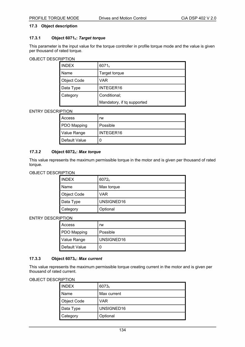
PROFILE TORQUE MODE Drives and Motion Control CiA DSP 402 V 2.0
134
17.3 Object description
17.3.1 Object 6071h: Target torque
This parameter is the input value for the torque controller in profile torque mode and the value is givenper thousand of rated torque.
OBJECT DESCRIPTION
INDEX 6071h
Name Target torque
Object Code VAR
Data Type INTEGER16
Category Conditional;
Mandatory, if tq supported
ENTRY DESCRIPTION
Access rw
PDO Mapping Possible
Value Range INTEGER16
Default Value 0
17.3.2 Object 6072h: Max torque
This value represents the maximum permissible torque in the motor and is given per thousand of ratedtorque.
OBJECT DESCRIPTION
INDEX 6072h
Name Max torque
Object Code VAR
Data Type UNSIGNED16
Category Optional
ENTRY DESCRIPTION
Access rw
PDO Mapping Possible
Value Range UNSIGNED16
Default Value 0
17.3.3 Object 6073h: Max current
This value represents the maximum permissible torque creating current in the motor and is given perthousand of rated current.
OBJECT DESCRIPTION
INDEX 6073h
Name Max current
Object Code VAR
Data Type UNSIGNED16
Category Optional

PROFILE TORQUE MODE Drives and Motion Control CiA DSP 402 V 2.0
135
ENTRY DESCRIPTION
Access rw
PDO Mapping Possible
Value Range UNSIGNED16
Default Value 0
17.3.4 Object 6074h: Torque demand value
This parameter is the output value of the torque limit function (if the torque control and power-stagefunction are available). The value is given per thousand of rated torque.
OBJECT DESCRIPTION
INDEX 6074h
Name Torque demand value
Object Code VAR
Data Type INTEGER16
Category Optional
ENTRY DESCRIPTION
Access ro
PDO Mapping Possible
Value Range INTEGER16
Default Value 0
17.3.5 Object 6075h: Motor rated current
This value is taken from the motor name plate and is entered as multiples of milliamp. Depending onthe motor and drive technology this current may be either DC, peak or rms (root-mean-square)current. All relative current data refers to this value.
OBJECT DESCRIPTION
INDEX 6075h
Name Motor rated current
Object Code VAR
Data Type UNSIGNED32
Category Optional
ENTRY DESCRIPTION
Access rw
PDO Mapping Possible
Value Range UNSIGNED32
Default Value 0

PROFILE TORQUE MODE Drives and Motion Control CiA DSP 402 V 2.0
136
17.3.6 Object 6076h: Motor rated torque
This value is taken from the motor name plate and is entered as multiples of mNm (mill Newtonmeter).All relative torque data refer to this value.
For linear motors, the object name is not changed, but the motor rated force value must be entered asmultiples of mN (mill Newton).
OBJECT DESCRIPTION
INDEX 6076h
Name Motor rated torque
Object Code VAR
Data Type UNSIGNED32
Category Optional
ENTRY DESCRIPTION
Access rw
PDO Mapping Possible
Value Range UNSIGNED32
Default Value 0
17.3.7 Object 6077h: Torque actual value
The torque actual value corresponds to the instantaneous torque in the drive motor. The value is givenper thousand of rated torque.
OBJECT DESCRIPTION
INDEX 6077h
Name Torque actual value
Object Code VAR
Data Type INTEGER16
Category Optional
ENTRY DESCRIPTION
Access ro
PDO Mapping Possible
Value Range INTEGER16
Default Value 0
17.3.8 Object 6078h: Current actual value
The current actual value refers to the instantaneous current in the drive motor. The value is given perthousand of rated current.
OBJECT DESCRIPTION
INDEX 6078h
Name Current actual value
Object Code VAR
Data Type INTEGER16
Category Optional

PROFILE TORQUE MODE Drives and Motion Control CiA DSP 402 V 2.0
137
ENTRY DESCRIPTION
Access ro
PDO Mapping Possible
Value Range INTEGER16
Default Value 0
17.3.9 Object 6079h: DC link circuit voltage
This parameter describes the instantaneous DC link current voltage at the drive controller. The valueis given in multiples of mill volts.
OBJECT DESCRIPTION
INDEX 6079h
Name DC link circuit voltage
Object Code VAR
Data Type UNSIGNED32
Category Optional
ENTRY DESCRIPTION
Access ro
PDO Mapping Possible
Value Range UNSIGNED32
Default Value 0
17.3.10 Object 6087h: Torque slope
This parameter describes the rate of change of torque in units of per thousand of rated torque persecond.
OBJECT DESCRIPTION
INDEX 6087h
Name Torque slope
Object Code VAR
Data Type UNSIGNED32
Category Conditional;
Mandatory, if tq supported
ENTRY DESCRIPTION
Access rw
PDO Mapping Possible
Value Range UNSIGNED32
Default Value 0

PROFILE TORQUE MODE Drives and Motion Control CiA DSP 402 V 2.0
138
17.3.11 Object 6088h: Torque profile type
The torque profile type is used to select the type of torque profile used to perform a torque change.
OBJECT DESCRIPTION
INDEX 6088h
Name Torque profile type
Object Code VAR
Data Type INTEGER16
Category Conditional;
Mandatory, if tq supported
ENTRY DESCRIPTION
Access rw
PDO Mapping Possible
Value Range INTEGER16
Default Value 0
DATA DESCRIPTION
Value Description
0000h Linear ramp (trapezoidal profile)
0001h sin2 ramp
0002h .. 7FFFh reserved
8000h .. FFFFh manufacturer specific
17.3.12 Object 60F7h: Power stage parameters
The power stage parameters object is used to handle (i.e. download) all manufacturer-specific power-stage parameters in a whole, in a standard way.
OBJECT DESCRIPTION
INDEX 60F7h
Name Power stage parameters
Object Code RECORD
Data Type manufacturer specific
Category Optional
ENTRY DESCRIPTION
Sub-Index 0
Description number of entries
Entry Category Mandatory
Access ro
PDO Mapping No
Value Range 1 .. 254
Default Value No

PROFILE TORQUE MODE Drives and Motion Control CiA DSP 402 V 2.0
139
Sub-Index 1
Description manufacturer specific
Entry Category Mandatory
Access manufacturer specific
PDO Mapping manufacturer specific
Value Range manufacturer specific
Default Value No
Sub-Index 2
Description manufacturer specific
Entry Category Optional
Access manufacturer specific
PDO Mapping manufacturer specific
Value Range manufacturer specific
Default Value No
to
Sub-Index 254
Description manufacturer specific
Entry Category Optional
Access manufacturer specific
PDO Mapping manufacturer specific
Value Range manufacturer specific
Default Value No
17.3.13 Object 60F6h: Torque control parameters
The torque control parameters object is used to handle (i.e. download) all manufacturer-specific torquecontrol parameters in a whole, in a standard way.
OBJECT DESCRIPTION
INDEX 60F6h
Name Torque control parameters
Object Code RECORD
Data Type manufacturer specific
Category Optional

PROFILE TORQUE MODE Drives and Motion Control CiA DSP 402 V 2.0
140
ENTRY DESCRIPTION
Sub-Index 0
Description number of entries
Entry Category Mandatory
Access ro
PDO Mapping No
Value Range 1 .. 254
Default Value No
Sub-Index 1
Description manufacturer specific
Entry Category Mandatory
Access manufacturer specific
PDO Mapping manufacturer specific
Value Range manufacturer specific
Default Value No
Sub-Index 2
Description manufacturer specific
Entry Category Optional
Access manufacturer specific
PDO Mapping manufacturer specific
Value Range manufacturer specific
Default Value No
to
Sub-Index 254
Description manufacturer specific
Entry Category Optional
Access manufacturer specific
PDO Mapping manufacturer specific
Value Range manufacturer specific
Default Value No
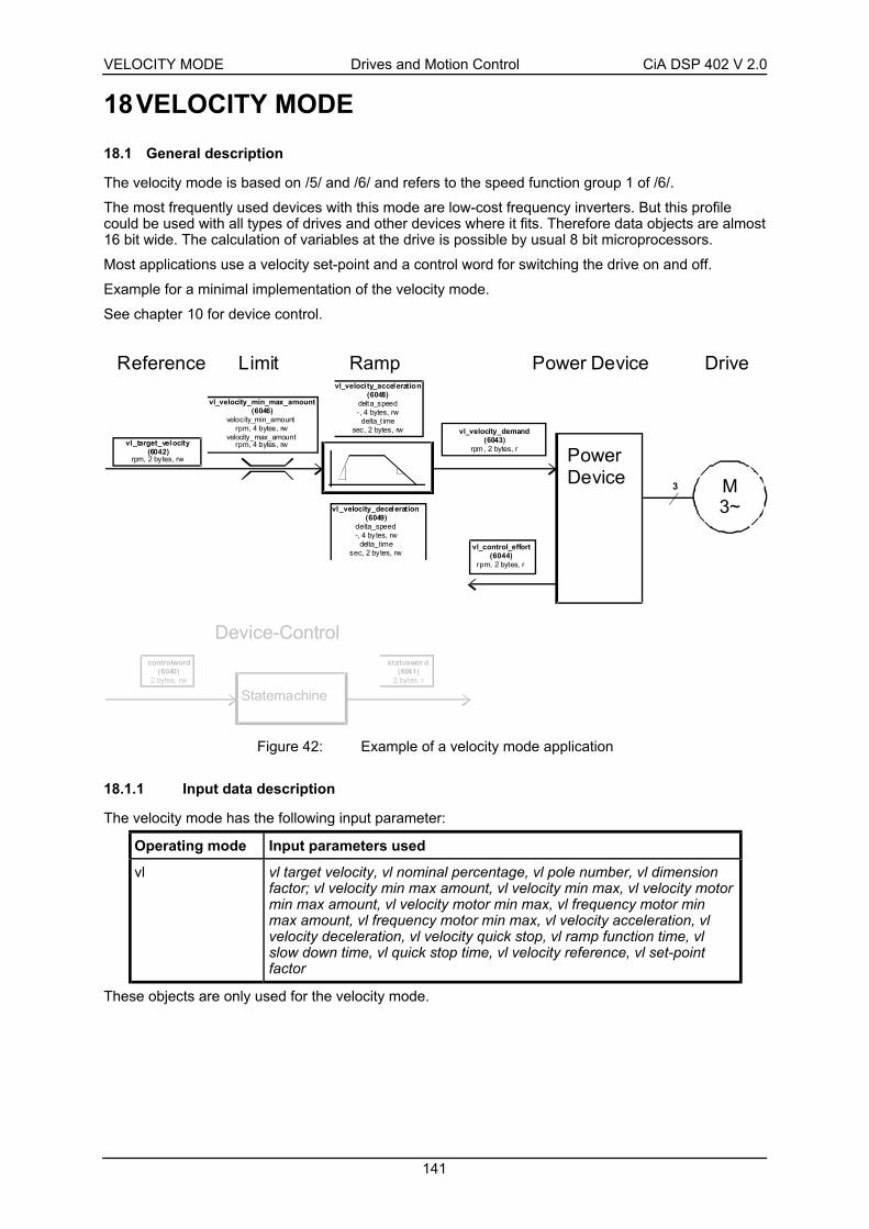
VELOCITY MODE Drives and Motion Control CiA DSP 402 V 2.0
141
18 VELOCITY MODE
18.1 General description
The velocity mode is based on /5/ and /6/ and refers to the speed function group 1 of /6/.
The most frequently used devices with this mode are low-cost frequency inverters. But this profilecould be used with all types of drives and other devices where it fits. Therefore data objects are almost16 bit wide. The calculation of variables at the drive is possible by usual 8 bit microprocessors.
Most applications use a velocity set-point and a control word for switching the drive on and off.
Example for a minimal implementation of the velocity mode.
See chapter 10 for device control.
Power Device
Reference Limit Ramp Power Device
M3~
3
vl_target_velocity(6042)
rpm, 2 bytes, rw
vl_velocity_min_max_amount(6046)
velocity_min_amountrpm, 4 bytes, rw
velocity_max_amountrpm, 4 bytes, rw
vl_veloci ty_acceleration(6048)
delta_speed-, 4 bytes, rw
delta_t imesec, 2 bytes, rw
vl_velocity_deceleration(6049)
delta_speed-, 4 bytes, rw
delta_timesec, 2 bytes, rw
vl_velocity_demand(6043)
rpm , 2 bytes, r
vl_control_effort(6044)
rpm, 2 bytes, r
Drive
Device-Controlstatuswor d
(6041)2 bytes, r
Statemachine
controlword(6040)
2 bytes, rw
Figure 42: Example of a velocity mode application
18.1.1 Input data description
The velocity mode has the following input parameter:
Operating mode Input parameters used
vl vl target velocity, vl nominal percentage, vl pole number, vl dimensionfactor; vl velocity min max amount, vl velocity min max, vl velocity motormin max amount, vl velocity motor min max, vl frequency motor minmax amount, vl frequency motor min max, vl velocity acceleration, vlvelocity deceleration, vl velocity quick stop, vl ramp function time, vlslow down time, vl quick stop time, vl velocity reference, vl set-pointfactor
These objects are only used for the velocity mode.

VELOCITY MODE Drives and Motion Control CiA DSP 402 V 2.0
142
18.1.2 Output data description
The velocity mode provides the following output parameters:
Operation mode Output parameter used
vl vl control effort, vl manipulated velocity, vl percentage demand, vl actualpercentage, vl velocity demand, vl manipulated percentage
These objects are only used for the velocity mode.
18.1.3 Structure of the velocity mode
The diagram below shows the overall structure of the velocity mode. All mandatory and optionalobjects are used. It is not intended with it to specify implementations, but to describe the scope offunctions. In these structures, the unit in which the velocity values in the speed functions arecalculated is rpm. The descriptions of the drive functions refer to this structure. The device control is ofcourse used in the velocity mode, but it is described in an extra chapter.
vl_target_velocity
Reference_calculationvl_nominal_percentage
vl_velocity_demand
Reverse_percentage_
function
vl_dimension_factor
vl_setpoint_factor
Velocity_limit
vl_velocity_min_max_amount
vl_velocity_min_max
statusword.11, limit_value
vl_velocity_quick_stop
Ramp_min_function
vl_velocity_decelaration
vl_velocity_accelaration Factor_function
vl_dimension_factor
Ramp_function
vl_ramp_function_time
vl_slow_down_time
vl_quick_stop_time
controlword.5, rfg_stop
Velocity_motor_ limit
speed_motor_min_max_amount
speed_motor_min_max
pole_number
frequency_motor_min_max_amount
frequency_motor_min_max
Factor_function
controlword.4, rfg_disable
controlword.6, rfg_zero
N4
controlword.8,halt

VELOCITY MODE Drives and Motion Control CiA DSP 402 V 2.0
143
Reverse_factor_function
vl_dimension_factor
vl_setpoint_factor vl_velocity_demand
vl_velocity_reference
Percentage_function
vl_percentage_demand
Closed_open_loop_control_function
statusword.10, speed
Reverse_factor_function
vl_dimension_factor
vl_setpoint_factor
vl_control_effort
vl_velocity_reference Percentage_function
vl_actual_percentage
Reverse_factor_function
vl_dimension_factor
vl_setpoint_factor vl_manipulated_velocity
vl_velocity_reference
Percentage_function
vl_manipulated_percentage
N4
Figure 43: Velocity mode with all objects
All device using this profile and supporting the velocity mode have to implement the mandatory objectsand there functionality. The diagram below shows the structure all devices will have at minimum.

VELOCITY MODE Drives and Motion Control CiA DSP 402 V 2.0
144
Ramp function
s tatusword.11, l imit_value
Ramp function
vl_velocity_min_max_amount(6046h)
vl_target_velocity(6042h)
vl_velocity_acceleration(6048h)
vl_velocity_deceleration(6049h)
Closed-loopopen-loop
control function
vl_control_effort(6044)
vl_velocity_demand(6043h)
Figure 44: Velocity mode with mandatory objects only
18.1.4 Sub-function description
The velocity mode is composed of the following sub-functions:
• Reference calculation,
• Factor function, Reverse factor function,
• Percentage function, Reverse percentage function,
• Pole number function, Reverse pole number function,
• Velocity limit function,
• Velocity motor limit function,
• Ramp function,
• Ramp min function, and
• Closed open loop control function.
These sub-functions are only used for the velocity mode.
18.1.5 Internal states
18.1.5.1 Controlword of velocity mode
15 9 8 7 6 5 4 3 0
(see 10.3.1) Halt (see 10.3.1) rfg use ref rfg unlock rfg enable (see 10.3.1)
MSB LSB

VELOCITY MODE Drives and Motion Control CiA DSP 402 V 2.0
145
Name Value Description
0 Velocity reference value is controlled inany other (manufacturer specific) way,e.g. by a test function generator ormanufacturer specific halt function.
rfg enable
1 Velocity reference value accords toramp output value.
0 Ramp output value is locked to currentoutput value.
rfg unlock
1 Ramp output value follows ramp inputvalue.
0 Ramp input value is set to zero.rfg use ref
1 Ramp input value accords to rampreference.
0 Execute motionHalt
1 Stop axle
Table 23: Velocity mode bits of the controlword
Figure 45: Controlword bits in the velocity mode
18.1.5.2 Statusword of velocity mode
15 14 13 12 11 10 9 0
(see 10.3.2) reserved (see 10.3.2) reserved (see 10.3.2)
MSB LSB
RFG0
Ramp_Reference
Lock_Output
Run_RFG
Bit 5
Bit 4
Bit 6
0
1
0
1
0
1
Ramp_Input_Value Ramp_Output_Value
SpecialFunctionGenerator
Velocity_Reference

VELOCITY MODE Drives and Motion Control CiA DSP 402 V 2.0
146
18.2 Complex data types
18.2.1 vl velocity acceleration deceleration record
Index Sub-Index
Field in vl velocity accelerationdeceleration record
Data type
0 number of entries UNSIGNED8
1 Delta speed UNSIGNED32
0082h
2 Delta time INTEGER16
18.3 Object dictionary entries
18.3.1 Objects defined in this chapter
Index Object Name Type Attr. M/O
6042h VAR vl target velocity INTEGER16 rw M
6043h VAR vl velocity demand INTEGER16 ro M
6044h VAR vl control effort INTEGER16 ro M
6045h VAR vl manipulated velocity INTEGER16 ro O
6046h ARRAY vl velocity min max amount UNSIGNED32 rw M
6047h ARRAY vl velocity min max UNSIGNED32 rw O
6048h RECORD vl velocity acceleration vl velocity accelerationdeceleration record
rw M
6049h RECORD vl velocity deceleration vl velocity accelerationdeceleration record
rw M
604Ah RECORD vl velocity quick stop vl velocity accelerationdeceleration record
rw O
604Bh ARRAY vl set-point factor INTEGER16 rw O
604Ch ARRAY vl dimension factor INTEGER32 rw O
604Dh VAR vl pole number UNSIGNED8 rw O
604Eh VAR vl velocity reference UNSIGNED32 rw O
604Fh VAR vl ramp function time UNSIGNED32 rw O
6050h VAR vl slow down time UNSIGNED32 rw O
6051h VAR vl quick stop time UNSIGNED32 rw O
6052h VAR vl nominal percentage INTEGER16 rw O
6053h VAR vl percentage demand INTEGER16 ro O
6054h VAR vl actual percentage INTEGER16 ro O
6055h VAR vl manipulated percentage INTEGER16 ro O
6056h ARRAY vl velocity motor min max amount UNSIGNED32 rw O
6057h ARRAY vl velocity motor min max UNSIGNED32 rw O
6058h ARRAY vl frequency motor min max amount UNSIGNED32 rw O
6059h ARRAY vl frequency motor min max UNSIGNED32 rw O

VELOCITY MODE Drives and Motion Control CiA DSP 402 V 2.0
147
18.3.2 Objects defined in other chapters
Index Object Name Type Chapter
603Fh VAR Error code UNSIGNED16 ce
6040h VAR Controlword UNSIGNED16 dc
6041h VAR Statusword UNSIGNED16 dc
605Ah VAR Quick stop option code INTEGER16 dc
605Bh VAR Shut down option code INTEGER16 dc
605Ch VAR Disable operation option code INTEGER16 dc
605Dh VAR Halt option code INTEGER16 dc
6060h VAR Modes of operation INTEGER8 dc
6061h VAR Modes of operation display INTEGER8 dc
18.4 Object description
18.4.1 Object 6042h: vl target velocity
The vl target velocity is the required velocity of the system. It is multiplied by the vl dimension factorand the vl set-point factor, if these are implemented. The vl target velocity is converted to the unit [rpm]by multiplying the vl target velocity by the vl dimension factor. The unit of the vl target velocity isinterpreted as rpm, if the vl dimension factor is not implemented or has the value 1.
OBJECT DESCRIPTION
INDEX 6042h
Name vl target velocity
Object Code VAR
Data Type INTEGER16
Category Conditional;
Mandatory, if vl supported
ENTRY DESCRIPTION
Access rw
PDO Mapping Possible
Value Range INTEGER16
Default Value 0

VELOCITY MODE Drives and Motion Control CiA DSP 402 V 2.0
148
18.4.2 Object 6043h: vl velocity demand
The vl velocity demand is the instantaneous velocity provided by the ramp function, scaled to the unitof the vl target velocity. The value ranges from -32768 to 32767 (INTEGER16). The parameter couldonly be read, because it is changed only by the drive.
OBJECT DESCRIPTION
INDEX 6043h
Name vl velocity demand
Object Code VAR
Data Type INTEGER16
Category Conditional;
Mandatory, if vl supported
ENTRY DESCRIPTION
Access ro
PDO Mapping Possible
Value Range INTEGER16
Default Value No
18.4.3 Object 6053h: vl percentage demand
The vl percentage demand is calculated on the basis of the vl velocity demand by using thepercentage function. It is the velocity provided by the ramp function in percent. Accordingly, the vlpercentage demand is within the same value range as the vl nominal percentage. The value rangesfrom -32768 to 32767 (INTEGER16). The value 16383 corresponds to 100% of the vl velocityreference. Accordingly, an indication range of +/- 200% is possible. The parameter is read-only.
OBJECT DICTIONARY
INDEX 6053h
Name vl percentage demand
Object Code VAR
Data Type INTEGER16
Category Optional
ENTRY DESCRIPTION
Access ro
PDO Mapping Possible
Value Range INTEGER16
Default Value No

VELOCITY MODE Drives and Motion Control CiA DSP 402 V 2.0
149
18.4.4 Object 6054h: vl actual percentage
The vl actual percentage is calculated on the basis of the vl control effort by using the percentagefunction. In this way, the vl actual percentage has the same value range as the vl nominal percentage.The value ranges from -32768 to 32767 (INTEGER16). The value 16383 corresponds to 100% of thevl velocity reference. Therefore, an indication range of +/- 200% is possible.
OBJECT DESCRIPTION
INDEX 6054h
Name vl actual percentage
Object Code VAR
Data Type INTEGER16
Category Optional
ENTRY DESCRIPTION
Access ro
PDO Mapping Possible
Value Range INTEGER16
Default Value No
18.4.5 Object 6055h: vl manipulated percentage
The vl manipulated percentage is calculated on the basis of the vl manipulated velocity. In this way,the vl manipulated percentage is shown in the same value range as the vl nominal percentage. Thevalue ranges from -32768 to 32767 (INTEGER16). The value 16383 corresponds to 100% of the vlvelocity reference. Therefore, an indication range of +/- 200% is possible.
OBJECT DESCRIPTION
INDEX 6055h
Name vl manipulated percentage
Object Code VAR
Data Type INTEGER16
Category Optional
ENTRY DESCRIPTION
Access ro
PDO Mapping Possible
Value Range INTEGER16
Default Value No
18.4.6 Object 604Eh: vl velocity reference
This parameter serves to represent velocity values (set-points, actual values and ramps) as relativevalues. If the vl velocity reference is modified, the ramps slopes, if objects vl ramp function time, vlslow down time or vl quick stop time are implemented, are changed relative to the change in the vlvelocity reference.
This parameter has the same unit as the vl target velocity and the following value range:0 .. 4.294.967.295 (UNSIGNED32).

VELOCITY MODE Drives and Motion Control CiA DSP 402 V 2.0
150
OBJECT DESCRIPTION
INDEX 604Eh
Name vl velocity reference
Object Code VAR
Data Type UNSIGNED32
Category Optional
ENTRY DESCRIPTION
Access rw
PDO Mapping Possible
Value Range UNSIGNED32
Default Value No
CONVERTING PERCENTAGES TO VELOCITY VALUES
Velocity value = Percentage
3FFFh
⋅ vl velocity reference
CONVERTING VELOCITY VALUES TO PERCENTAGES
Percentage = Velocity value 3FFF
h⋅
vl velocity reference
18.4.7 Object 604Ch: vl dimension factor
The vl dimension factor is generated by division using the sub-parameter numerator and the sub-parameter denominator. These parameter have a value ranging from –2.147.483.648 to2.147.483.647 (INTEGER32), but except the value 0!
The vl dimension factor serves to include gearing in calculation or serves to scale the frequencies orspecific units of the user. It influences the specified set-point, the velocity limit and the ramp functionas well as the output variables of the speed function.
OBJECT DESCRIPTION
INDEX 604Ch
Name vl dimension factor
Object Code ARRAY
Data Type INTEGER32
Category Optional
ENTRY DESCRIPTION
Sub-Index 0
Description number of entries
Entry Category Mandatory
Access ro
PDO Mapping No
Value Range 2
Default Value 2

VELOCITY MODE Drives and Motion Control CiA DSP 402 V 2.0
151
Sub-Index 1
Description vl dimension factor numerator
Entry Category Mandatory
Access rw
PDO Mapping Possible
Value Range INTEGER32
Default Value 1
Sub-Index 2
Description vl dimension factor denominator
Entry Category Mandatory
Access rw
PDO Mapping Possible
Value Range INTEGER32
Default Value 1
CALCULATING THE VL DIMENSION FACTOREvery user specific speed consists of a specific unit referred to a specific unit of time (e.g. 1/sec,bottles/min, m/sec,...).
The purpose of the dimension factor is to convert this specific unit to the revolutions/minute unit.
Specific unit * DF = 1 revolution (motor shaft)
I DF O⋅ =I = vl target velocity expressed as the user’s specific speed
Input value of the factor function
Unit of I: [I] = Specific unit
O = Speed value in [rpm]
Output value of the factor function
Unit of O: O1
min
Revolution
min[ ] = =
DF = Dimension factor
Unit of DF: [DF] = 1
Specific unit *
1
min

VELOCITY MODE Drives and Motion Control CiA DSP 402 V 2.0
152
18.4.8 Object 604Bh: vl set-point factor
The vl set-point factor is generated by division, using a numerator sub-parameter and a denominatorsub-parameter. These sub-parameters have no unit and have values within a range from -32768 to32767 (INTEGER16), but excluding the value 0!
The vl set-point factor serves to modify the resolution or directing range of the specified set-point. It isincluded in calculation of the specified set-point and the output variables of the speed function only.
OBJECT DESCRIPTION
INDEX 604Bh
Name vl set-point factor
Object Code ARRAY
Data Type INTEGER16
Category Optional
ENTRY DESCRIPTION
Sub-Index 0
Description number of entries
Entry Category Mandatory
Access ro
PDO Mapping No
Value Range 2
Default Value 2
Sub-Index 1
Description vl set-point factor numerator
Entry Category Mandatory
Access rw
PDO Mapping Possible
Value Range INTEGER16
Default Value 1
Sub-Index 2
Description vl set-point factor denominator
Entry Category Mandatory
Access rw
PDO Mapping Possible
Value Range INTEGER16
Default Value 1

VELOCITY MODE Drives and Motion Control CiA DSP 402 V 2.0
153
18.4.9 Object 604Dh: vl pole number
The user must describe the vl pole number parameter with a value corresponding to the number ofpoles belonging to the connected motor. This parameter has no unit. The value range depends on themanufacturer-specific need and is represented as UNSIGNED8. If the Object vl pole number does fitfor the desired type of motor, this object could left out or set to value 2.
OBJECT DESCRIPTION
INDEX 604Dh
Name vl pole number
Object Code VAR
Data Type UNSIGNED8
Category Optional
ENTRY DESCRIPTION
Access rw
PDO Mapping possible
Value Range Unsigned8
Default Value No
If the number of pole pairs is known, the number of poles is: = 2 pole pairsvl pole number ⋅
CONVERTING VELOCITY VALUES TO FREQUENCY VALUES
Frequency = Velocity ⋅
⋅
vl pole number
60 2
CONVERTING FREQUENCY VALUES TO VELOCITY VALUES
Velocity = Frequency 60 2⋅ ⋅
vl pole number
18.4.10 Object 6046h: vl velocity min max amount
The vl velocity min max amount parameter is composed of the vl velocity min amount and vl velocitymax amount sub-parameter. These sub-parameters don’t have units and have values within a rangefrom 0 to 4.294.967.295 (UNSIGNED32):
The vl velocity max amount sub-parameter is mapped internally to the vl velocity max pos and vlvelocity max neg values. The vl velocity min amount sub-parameter is mapped internally to the vlvelocity min pos and vl velocity min neg values.
Only the positive values are returned if the vl velocity min max amount parameter is read out.
OBJECT DESCRIPTION
INDEX 6046h
Name vl velocity min max amount
Object Code ARRAY
Data Type UNSIGNED32
Category Mandatory, if vl supported

VELOCITY MODE Drives and Motion Control CiA DSP 402 V 2.0
154
ENTRY DESCRIPTION
Sub-Index 0
Description number of entries
Entry Category Mandatory
Access ro
PDO Mapping No
Value Range 2
Default Value 2
Sub-Index 1
Description vl velocity min amount
Entry Category Mandatory
Access rw
PDO Mapping Possible
Value Range UNSIGNED32
Default Value No
Sub-Index 2
Description vl velocity max amount
Entry Category Mandatory
Access rw
PDO Mapping Possible
Value Range UNSIGNED32
Default Value No
This transfer characteristic results from vl velocity min max amount
0
+vl_velocity_min_amount
+vl_velocity_max_amount
-vl_velocity_min_amount
-vl_velocity_max_amount
output
input
Figure 46: vl velocity min max amount transfer characteristic
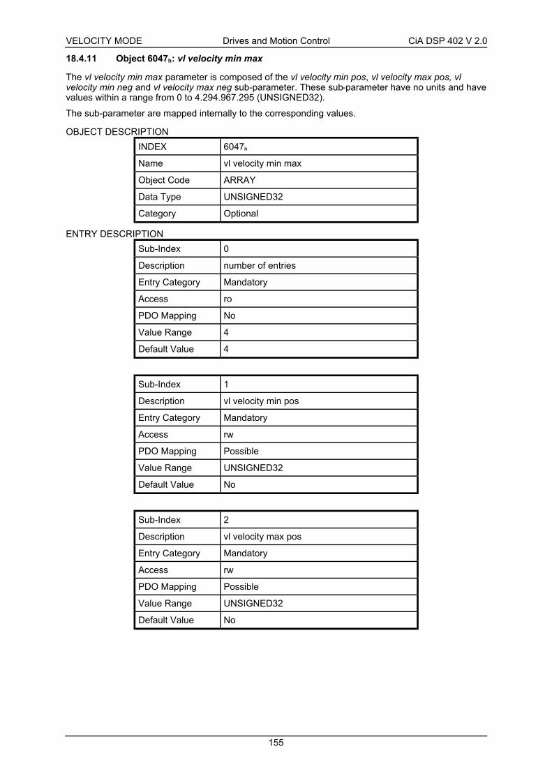
VELOCITY MODE Drives and Motion Control CiA DSP 402 V 2.0
155
18.4.11 Object 6047h: vl velocity min max
The vl velocity min max parameter is composed of the vl velocity min pos, vl velocity max pos, vlvelocity min neg and vl velocity max neg sub-parameter. These sub-parameter have no units and havevalues within a range from 0 to 4.294.967.295 (UNSIGNED32).
The sub-parameter are mapped internally to the corresponding values.
OBJECT DESCRIPTION
INDEX 6047h
Name vl velocity min max
Object Code ARRAY
Data Type UNSIGNED32
Category Optional
ENTRY DESCRIPTION
Sub-Index 0
Description number of entries
Entry Category Mandatory
Access ro
PDO Mapping No
Value Range 4
Default Value 4
Sub-Index 1
Description vl velocity min pos
Entry Category Mandatory
Access rw
PDO Mapping Possible
Value Range UNSIGNED32
Default Value No
Sub-Index 2
Description vl velocity max pos
Entry Category Mandatory
Access rw
PDO Mapping Possible
Value Range UNSIGNED32
Default Value No

VELOCITY MODE Drives and Motion Control CiA DSP 402 V 2.0
156
Sub-Index 3
Description vl velocity min neg
Entry Category Mandatory
Access rw
PDO Mapping Possible
Value Range UNSIGNED32
Default Value No
Sub-Index 4
Description vl velocity max neg
Entry Category Mandatory
Access rw
PDO Mapping Possible
Value Range UNSIGNED32
Default Value No
This transfer characteristic results from vl velocity min max
0+vl_velocity_min_pos
+vl_velocity_max_pos
-vl_velocity_min_neg
-vl_velocity_max_neg
output
input
Figure 47: vl velocity min max transfer characteristic
18.4.12 Object 6058h: vl frequency motor min max amount
The frequency parameter of the vl frequency motor min max amount objects are mapped internally tothe parameter of the corresponding speed objects.
OBJECT DESCRIPTION
INDEX 6058h
Name vl frequency motor min max amount
Object Code ARRAY
Data Type UNSIGNED32
Category Optional

VELOCITY MODE Drives and Motion Control CiA DSP 402 V 2.0
157
ENTRY DESCRIPTION
Sub-Index 0
Description number of entries
Entry Category Mandatory
Access ro
PDO Mapping No
Value Range 2
Default Value 2
Sub-Index 1
Description vl frequency motor min amount
Entry Category Mandatory
Access rw
PDO Mapping Possible
Value Range UNSIGNED32
Default Value No
Sub-Index 2
Description vl frequency motor max amount
Entry Category Mandatory
Access rw
PDO Mapping Possible
Value Range UNSIGNED32
Default Value No
This transfer characteristic results from vl frequency motor min max amount
0
+vl_frequency_motor_min_amount
+vl_frequency_motor_max_amount
-vl_frequency_motor_min_amount
-vl_frequency_motor_max_amount
output
input
Figure 48: vl frequency motor min max amount transfer characteristic

VELOCITY MODE Drives and Motion Control CiA DSP 402 V 2.0
158
18.4.13 Object 6059h: vl frequency motor min max
The frequency parameter of the vl frequency motor min max objects are mapped internally to theparameter of the corresponding speed objects.
OBJECT DESCRIPTION
INDEX 6059h
Name vl frequency motor min max
Object Code ARRAY
Data Type UNSIGNED32
Category Optional
ENTRY DESCRIPTION
Sub-Index 0
Description number of entries
Entry Category Mandatory
Access ro
PDO Mapping No
Value Range 4
Default Value 4
Sub-Index 1
Description vl frequency motor min pos
Entry Category Mandatory
Access rw
PDO Mapping Possible
Value Range UNSIGNED32
Default Value No
Sub-Index 2
Description vl frequency motor max pos
Entry Category Mandatory
Access rw
PDO Mapping Possible
Value Range UNSIGNED32
Default Value No

VELOCITY MODE Drives and Motion Control CiA DSP 402 V 2.0
159
Sub-Index 3
Description vl frequency motor min neg
Entry Category Mandatory
Access rw
PDO Mapping Possible
Value Range UNSIGNED32
Default Value No
Sub-Index 4
Description vl frequency motor max neg
Entry Category Mandatory
Access rw
PDO Mapping Possible
Value Range UNSIGNED32
Default Value No
This transfer characteristic results from vl velocity min max
0+vl_frequency_motor_min_pos
+vl_frequency_motor_max_pos
-vl_frequency_motor_min_neg
-vl_frequency_motor_max_neg
output
input
Figure 49: vl velocity min max transfer characteristic
18.4.14 Object 6056h: vl velocity motor min max amount
The vl velocity motor min max amount parameter is composed of the vl velocity motor min amount andvl velocity motor max amount parameter. These sub-parameters have the unit [(1/1000) rpm] andvalues within a range from 0 to 4.294.967.295 [(1/1000) rpm] (UNSIGNED32). This results in a limitingrange from 0 to 4.294.967.295 [rpm].
The vl velocity motor max amount sub-parameter is mapped internally to the vl velocity motor max posand vl velocity motor max neg values. The vl velocity motor min amount sub-parameter is mappedinternally to the vl velocity motor min pos and vl velocity motor min neg values.
Only the positive values are returned, if the vl velocity motor min max amount parameter is read.
OBJECT DESCRIPTION
INDEX 6056h
Name vl velocity motor min max amount
Object Code ARRAY
Data Type UNSIGNED32
Category Optional

VELOCITY MODE Drives and Motion Control CiA DSP 402 V 2.0
160
ENTRY DESCRIPTION
Sub-Index 0
Description number of entries
Entry Category Mandatory
Access ro
PDO Mapping No
Value Range 2
Default Value 2
Sub-Index 1
Description vl velocity motor min amount
Entry Category Mandatory
Access rw
PDO Mapping Possible
Value Range UNSIGNED32
Default Value No
Sub-Index 2
Description vl velocity motor max amount
Entry Category Mandatory
Access rw
PDO Mapping Possible
Value Range UNSIGNED32
Default Value No
This transfer characteristic results from vl velocity motor min max amount
0
+vl_velocity_motor_min_amount
+vl_velocity_motor_max_amount
-vl_velocity_motor_min_amount
-vl_velocity_motor_max_amount
output
input
Figure 50: vl velocity motor min max amount transfer characteristic

VELOCITY MODE Drives and Motion Control CiA DSP 402 V 2.0
161
18.4.15 Object 6057h: vl velocity motor min max
The vl velocity motor min max parameter is composed of the vl velocity motor min pos, vl velocitymotor max pos, vl velocity motor min neg and vl velocity motor max neg sub-parameter. These sub-parameters have the unit [1/(1000 min)] and values within a range from 0 ... 4.294.967.295 [1/(1000min)] (UNSIGNED32). This results in a limiting range from 0 ... 4.294.967 [rpm].
The sub-parameter are mapped internally to the corresponding values.
OBJECT DESCRIPTION
INDEX 6057h
Name vl velocity motor min max
Object Code ARRAY
Data Type UNSIGNED32
Category Optional
ENTRY DESCRIPTION
Sub-Index 0
Description number of entries
Entry Category Mandatory
Access ro
PDO Mapping No
Value Range 4
Default Value 4
Sub-Index 1
Description vl velocity motor min pos
Entry Category Mandatory
Access rw
PDO Mapping Possible
Value Range UNSIGNED32
Default Value No
Sub-Index 2
Description vl velocity motor max pos
Entry Category Mandatory
Access rw
PDO Mapping Possible
Value Range UNSIGNED32
Default Value No

VELOCITY MODE Drives and Motion Control CiA DSP 402 V 2.0
162
Sub-Index 3
Description vl velocity motor min neg
Entry Category Mandatory
Access rw
PDO Mapping Possible
Value Range UNSIGNED32
Default Value No
Sub-Index 4
Description vl velocity motor max neg
Entry Category Mandatory
Access rw
PDO Mapping Possible
Value Range UNSIGNED32
Default Value No
This transfer characteristic results from vl velocity min max
0+vl_velocity_motor_min_pos
+vl_velocity_motor_max_pos
-vl_velocity_motor_min_neg
-vl_velocity_motor_max_neg
output
input
Figure 51: vl velocity min max transfer characteristic
LIMIT-VALUEThe Limit-value message is generated, if the input value of the velocity motor limit function results in avalue outside of the operating range of the velocity motor limit function. The Limit-value message ismapped as one bit in the statusword.
18.4.16 Object 6048h: vl velocity acceleration
The vl velocity acceleration parameter specifies the slope of the acceleration ramp. It is generated asthe quotient of the delta speed and delta time sub-parameter.
OBJECT DESCRIPTION
INDEX 6048h
Name vl velocity acceleration
Object Code RECORD
Data Type vl velocity acceleration deceleration record (0082h)
Category Conditional;
Mandatory, if vl supported

VELOCITY MODE Drives and Motion Control CiA DSP 402 V 2.0
163
ENTRY DESCRIPTION
Sub-Index 0
Description number of entries
Entry Category Mandatory
Access ro
PDO Mapping No
Value Range 2
Default Value 2
Sub-Index 1
Description Delta speed
Entry Category Mandatory
Access rw
PDO Mapping Possible
Value Range UNSIGNED32
Default Value No
Sub-Index 2
Description Delta time
Entry Category Mandatory
Access rw
PDO Mapping Possible
Value Range UNSIGNED16
Default Value No
DELTA SPEEDThe delta speed has the same unit as the vl target velocity. This sub-parameter has the value range: 0... 4.294.967.295 (UNSIGNED32).
DELTA TIMEThis sub-parameter is specified in sec and has the value range: 0 ... 65.535 [sec] (UNSIGNED16).
This function directly follows the set-point if the parameter 0 is defined for the delta time value.
vl velocity acceleration delta speed
delta timeaB= =
delta
_spe
ed
time
velo
city
delta_time
Figure 52: vl velocity acceleration transfer characteristic

VELOCITY MODE Drives and Motion Control CiA DSP 402 V 2.0
164
18.4.17 Object 6049h: vl velocity deceleration
The vl velocity deceleration parameter specifies the slope of the deceleration ramp. It is generated asthe quotient of the delta speed and delta time sub-parameter.
OBJECT DESCRIPTION
INDEX 6049h
Name vl velocity deceleration
Object Code RECORD
Data Type vl velocity acceleration deceleration record (0082h)
Category Conditional;
Mandatory, if vl supported
ENTRY DESCRIPTION
Sub-Index 0
Description number of entries
Entry Category Mandatory
Access ro
PDO Mapping No
Value Range 2
Default Value 2
Sub-Index 1
Description Delta speed
Entry Category Mandatory
Access rw
PDO Mapping Possible
Value Range UNSIGNED32
Default Value No
Sub-Index 2
Description Delta time
Entry Category Mandatory
Access rw
PDO Mapping Possible
Value Range UNSIGNED16
Default Value No
DELTA SPEEDThe delta speed has the same unit as the vl target velocity. This sub-parameter has the value range: 0... 4.294.967.295 (UNSIGNED32).
DELTA TIMEThis sub-parameter is specified in sec and has the value range: 0 ... 65.535 [sec] (UNSIGNED16).
This function directly follows the set-point, if the value 0 is defined for the delta time parameter.

VELOCITY MODE Drives and Motion Control CiA DSP 402 V 2.0
165
vl velocity deceleration delta speed
delta timeaV= =
delta
_spe
ed
time
velo
city
delta_time
Figure 53: vl velocity deceleration transfer characteristic
18.4.18 Object 604Ah: vl velocity quick stop
The vl velocity quick stop parameter specifies the slope of the quick stop ramp. It is generated as thequotient of the delta speed and delta time sub-parameter.
OBJECT DESCRIPTION
INDEX 604Ah
Name vl velocity quick stop
Object Code RECORD
Data Type vl velocity acceleration deceleration record (0082h)
Category Optional
ENTRY DESCRIPTION
Sub-Index 0
Description number of entries
Entry Category Mandatory
Access ro
PDO Mapping No
Value Range 2
Default Value 2
Sub-Index 1
Description Delta speed
Entry Category Mandatory
Access rw
PDO Mapping Possible
Value Range UNSIGNED32
Default Value No

VELOCITY MODE Drives and Motion Control CiA DSP 402 V 2.0
166
Sub-Index 2
Description Delta speed
Entry Category Mandatory
Access rw
PDO Mapping Possible
Value Range UNSIGNED16
Default Value No
DELTA SPEEDThe delta speed has the same unit as the vl target velocity. This sub-parameter has the value range: 0... 4.294.967.295 (UNSIGNED32).
DELTA_TIMEThis sub-parameter is specified in sec and has the value range: 0 ... 65.535 [sec] (UNSIGNED16).
This function directly follows the set-point, if the parameter 0 is defined for the delta time value.
velocity quick stop delta speed
delta timeaS= =
delta
_spe
ed
time
velo
city
delta_time
Figure 54: vl velocity quick stop transfer characteristic
18.4.19 Object 604Fh: vl ramp function time
The vl ramp function time specifies the time during which the drive starts up from zero to the vl velocityreference.
time
velocity
0
speed_reference_v alue
ramp_function_time
Figure 55: vl ramp function time transfer characteristic
This parameter is specified in ms and has the value range: 0 … 4.294.967.295 [ms] (UNSIGNED32).
By setting the parameter 0 for the vl ramp function time, the ramp becomes infinite and the referencevariable directly follows the set-point.

VELOCITY MODE Drives and Motion Control CiA DSP 402 V 2.0
167
OBJECT DESCRIPTION
INDEX 604Fh
Name vl ramp function time
Object Code VAR
Data Type UNSIGNED32
Category Optional
ENTRY DESCRIPTION
Access rw
PDO Mapping Possible
Value Range UNSIGNED32
Default Value No
18.4.20 Object 6050h: vl slow down time
The vl slow down time specifies the time during which the drive slows down from vl velocity referenceto zero.
time
velocity
0
vl_velocity_reference
vl_slow_down_time
Figure 56: vl slow down time transfer characteristic
This parameter is specified in ms and has the value range: 0 ... 4.294.967.295 [ms] (UNSIGNED32).
By defining the parameter 0 for the vl slow down time, the ramp becomes infinite and the referencevariable directly follows the set-point.
OBJECT DESCRIPTION
INDEX 6050h
Name vl slow down time
Object Code VAR
Data Type UNSIGNED32
ENTRY DESCRIPTION
Access rw
PDO Mapping Possible
Value Range UNSIGNED32
Default Value No

VELOCITY MODE Drives and Motion Control CiA DSP 402 V 2.0
168
18.4.21 Object 6051h: vl quick stop time
The vl quick stop time specifies the time during which the drive slows down from vl velocity referenceto zero in the QUICK STOP ACTIVE state.
time
velocity
0
vl_velocity_reference
vl_quick_stop_time
Figure 57: vl quick stop time transfer characteristic
This parameter is specified in ms and has the value range: 0 ... 4.294.967.295 [ms] (UNSIGNED32).
By defining the parameter 0 for the vl quick stop time, the ramp becomes infinite and the referencevariable directly follows the set-point.
OBJECT DESCRIPTION
INDEX 6051h
Name vl quick stop time
Object Code VAR
Data Type UNSIGNED32
Category Optional
ENTRY DESCRIPTION
Access rw
PDO Mapping Possible
Value Range UNSIGNED32
Default Value No
18.4.22 Object 6044h: vl control effort
The vl control effort is the velocity at the motor spindle or load, scaled to the unit of the vl targetvelocity. Depending on the system, velocity deviations may occur between the vl control effort and thephysical velocity. For simple drives without closed loop control or observer this value reads the objectvl velocity demand. The value ranges from –32.768 to 32.767 (INTEGER16).
OBJECT DESCRIPTION
INDEX 6044h
Name vl control effort
Object Code VAR
Data Type INTEGER16
Category Conditional;
Mandatory, if vl supported

VELOCITY MODE Drives and Motion Control CiA DSP 402 V 2.0
169
ENTRY DESCRIPTION
Access ro
PDO Mapping Possible
Value Range INTEGER16
Default Value No
18.4.23 Object 6045h: vl manipulated velocity
The vl manipulated velocity is the velocity of the motor spindle or load with a compensation value,scaled to the unit of the vl target velocity. The compensation value is generated by thecontroller/control function. The value ranges from –32.768 to 32.767 (INTEGER16).
OBJECT DESCRIPTION
INDEX 6045h
Name vl manipulated velocity
Object Code VAR
Data Type INTEGER16
Category Optional
ENTRY DESCRIPTION
Access ro
PDO Mapping Possible
Value Range INTEGER16
Default Value No
18.4.24 Object 6052h: vl nominal percentage
The vl nominal percentage is converted by the percent function to a velocity value. The vl nominalpercentage has no unit (better (100 / 16.383) %). Its value ranges from –32.768 to 32.767(INTEGER16). The value 16.383 corresponds to 100% of the vl velocity reference. Accordingly, a totalrange of the manipulated variable amounting to +/- 200% is possible.
OBJECT DESCRIPTION
INDEX 6052h
Name vl nominal percentage
Object Code VAR
Data Type INTEGER16
Category Optional
ENTRY DESCRIPTION
Access rw
PDO Mapping Possible
Value Range INTEGER16
Default Value No

VELOCITY MODE Drives and Motion Control CiA DSP 402 V 2.0
170
18.5 Functional description
18.5.1 Percentage function
The percentage function serves to convert percentages to velocity values (see Figure 58) and viceversa (see Figure 59).
3FFFh
DIV
vl_velocity_reference
MULvelocity, out
percent, in
Figure 58: Percentage function
3FFFh
DIV
vl_velocity_referenceMUL
percent, out
velocity, in
Figure 59: Reverse percentage function
18.5.2 Factor function and reverse factor function
The factor function multiplies the input variables by the assigned factors.
- The vl target velocity is multiplied by the vl dimension factor and the vl set-point factor.
- The values of the velocity limit and the values for the ramp function are only multiplied by the vldimension factor.
The factor has a value of 1, if it is not implemented.
The factor function for two factors is built of two function in series connection.
MULxxx_numerator
DIV
xxx_denominator
output
input
Figure 60: Factor function
The reverse factor function divides the input variables by the assigned factors.
- The output variables of the velocity mode are calculated by division with the vl dimension factor andthe vl set-point factor and therefore returned to the scaling of the specified set-point.

VELOCITY MODE Drives and Motion Control CiA DSP 402 V 2.0
171
MUL
xxx_numeratorDIV
xxx_denominator
output
input
Figure 61: Reverse factor function
18.5.3 Pole number function
The pole number function serves to convert frequency values to velocity values
DIVvl_pole_number
MUL
60 * 2
velocity, out
frequency, in
Figure 62: Pole number function
and vice versa
DIV
vl_pole_numberMUL
60 * 2
velocity, in
frequency, out
Figure 63: Reverse pole number function
18.5.4 Velocity limit function
The velocity limit defines the valid velocity range for the drive. Limits could be specified in the userspecific units by including the vl dimension factor in the speed limit.
LIMIT-VALUEThe Limit-value message is generated if the input value of the speed limit results in a value outside thespeed limit’s operating range. The Limit-value message is mapped as one bit in the statusword.
vl_velocity_min_max_amount
vl_velocity_min_max
vl_dimension_factor
COMPARERANGE FACTOR
FUNCTIONLIMITATION
velocity, out
velocity, in
statusword.11
Figure 64: Velocity limit function

VELOCITY MODE Drives and Motion Control CiA DSP 402 V 2.0
172
18.5.5 Velocity motor limit function
The velocity motor limit function limits the motor velocity range. This parameter has a safety functionthat ensures that the range of the set value of motor velocity cannot be exceeded inadvertently by amodification of a factor.
vl_frequency_motor_min_max_amount
vl_velocity_motor_min_max
vl_frequency_motor_min_max
vl_pole_number
COMPARERANGE POLE NUMBER
FUNCTION
LIMITATION
velocity, in
vl_velocity_motor_min_max_amount
velocity,out
COMPARERANGE
statusword.11
Figure 65: Velocity motor limit function
18.5.6 Ramp function
The ramp function is used to limit the increase and decrease of velocity. The velocity output is equal tothe input as long as the changes are below aBmin
, aVmin or aSmin
.
velo
city
.in
t
velo
city
.out
t
velo
city
t
acceleration at limit
Figure 66: Velocity profile
RAMP
velocity, in
velocity,out
aBminaVminaSmin
Figure 67: Ramp function

VELOCITY MODE Drives and Motion Control CiA DSP 402 V 2.0
173
The internal ramp values aBmin and aVmin
directly consist of the vl velocity acceleration and vl velocity
deceleration parameter.
The internal ramp values aBmin, aVmin
and aSmin are the output values of the ramp min function,
weighted with the vl dimension factor.
18.5.7 Ramp min function
The ramp min function selects the minimal change of velocity.
aB
aV
aS
aVmin
aBmin
aSmin
DIVMIN
vl_velocity_reference
ramp_function_time
DIVMIN
vl_velocity_reference
slow_down_time
DIV
MINvl_velocity_reference
quick_stop_time
Figure 68: Ramp min function
The internal ramp values ( aB min , aV min , aS min) are recalculated as follows, if one of the inputparameter for the ramp function is modified:
a avl velocity reference
vl ramp function timeB Bmin=
MIN ,
a avl velocity reference
vl slow down timeV Vmin=
MIN ,
a avl velocity reference
vl quick stop timeS Smin=
MIN ,
The ramp min function selects the lower respective value of the slopes.
18.5.8 Reference calculation
This sub-function decides on the set-point processing. The set-point value may be given as anpercentage and (or) as an absolute value. Therefore two objects are defined in this profile. The firstobject is the vl target velocity containing the absolute set-point value. This is an mandatory object forevery drive. Some drives may have implemented the object vl nominal percentage, which consist of anpercentage set-point value. So these manufactures have to specify how this two values are handled

VELOCITY MODE Drives and Motion Control CiA DSP 402 V 2.0
174
within the drive. Most profile implementations will add the percentage and the absolute set-point valueto calculate the internal set-point. It is also possible to use only one value. Then the last written objectis used internally.
18.5.9 Closed open loop control function
On the basis of the vl control effort, the controller/control function returns the vl control effort and the vlmanipulated velocity.
Depending on realization of the function, the vl control effort is the vl control effort or a calculated ormeasured vl control effort.
Depending on realization of the function, the vl manipulated velocity is the vl control effort or acalculated speed output.

AP
PE
ND
IXD
rives
and
Mot
ion
Con
trol
CiA
DS
P 4
02 V
2.0
175
19 A
PP
EN
DIX
19.1
O
bje
ct d
icti
on
ary
by
chap
ter
19.1
.1 C
om
mo
n e
ntr
ies
Man
dat
ory
/ O
pti
on
al /
Co
nd
itio
nal
Ind
exS
ub
Ob
ject
Nam
eT
ype
Att
r.P
DO
Map
pin
gal
lhm
pppc
ippv
tqvl
Un
its
Des
crip
tio
n
6007
h-
VA
RA
bort
con
nect
ion
optio
n co
deIN
TE
GE
R16
rwP
ossi
ble
O-
603F
h-
VA
RE
rror
cod
eU
NS
IGN
ED
16ro
Pos
sibl
eO
-
6402
h-
VA
RM
otor
type
UN
SIG
NE
D16
rwP
ossi
ble
O-
6403
h-
VA
RM
otor
cat
alog
num
ber
VIS
IBLE
_ST
RIN
Grw
No
O-
6404
h-
VA
RM
otor
man
ufac
ture
rV
ISIB
LE_S
TR
ING
rwN
oO
-
6405
h-
VA
Rht
tp m
otor
cat
alog
add
ress
VIS
IBLE
_ST
RIN
Grw
No
O-
6406
h-
VA
RM
otor
cal
ibra
tion
date
TIM
E_O
F_D
AY
rwP
ossi
ble
O-
6407
h-
VA
RM
otor
ser
vice
per
iod
UN
SIG
NE
D32
rwP
ossi
ble
O-
6410
h-
RE
CO
RD
Mot
or d
ata
(man
ufac
ture
r sp
ecifi
c)rw
-O
-
6502
h-
VA
RS
uppo
rted
driv
e m
odes
UN
SIG
NE
D32
roP
ossi
ble
O-
6503
h-
VA
RD
rive
cata
log
num
ber
VIS
IBLE
_ST
RIN
Grw
No
O-
6504
h-
VA
RD
rive
man
ufac
ture
rV
ISIB
LE_S
TR
ING
rwN
oO
-
6505
h-
VA
Rht
tp d
rive
cata
log
addr
ess
VIS
IBLE
_ST
RIN
Grw
No
O-
6510
h-
RE
CO
RD
Driv
e da
ta(m
anuf
actu
rer
spec
ific)
rw-
O-
60F
Dh
-V
AR
Dig
ital i
nput
sU
NS
IGN
ED
32ro
Pos
sibl
eO
-
-D
igita
l out
puts
--
O-
1P
hysi
cal o
utpu
tsrw
Pos
sibl
eM
-
60F
Eh
2
AR
RA
Y
Bitm
ask
UN
SIG
NE
D32
rwP
ossi
ble
O-

AP
PE
ND
IXD
rives
and
Mot
ion
Con
trol
CiA
DS
P 4
02 V
2.0
176
19.1
.2 D
evic
e co
ntr
ol
Man
dat
ory
/ O
pti
on
al /
Co
nd
itio
nal
Ind
exS
ub
Ob
ject
Nam
eT
ype
Att
r.P
DO
Map
pin
gal
lhm
pppc
ippv
tqvl
Un
its
Des
crip
tio
n
6040
h-
VA
RC
ontr
olw
ord
UN
SIG
NE
D16
rwP
ossi
ble
M-
6041
h-
VA
RS
tatu
swor
dU
NS
IGN
ED
16ro
Pos
sibl
eM
-
605B
h-
VA
RS
hutd
own
optio
n co
deIN
TE
GE
R16
rwN
oO
-
605C
h-
VA
RD
isab
le o
pera
tion
optio
n co
deIN
TE
GE
R16
rwN
oO
-
605A
h-
VA
RQ
uick
sto
p op
tion
code
INT
EG
ER
16rw
No
O-
605D
h-
VA
RH
alt o
ptio
n co
deIN
TE
GE
R16
rwN
oO
-
605E
h-
VA
RF
ault
reac
tion
optio
n co
deIN
TE
GE
R16
rwN
oO
-
6060
h-
VA
RM
odes
of o
pera
tion
INT
EG
ER
8rw
Pos
sibl
eM
-
6061
h-
VA
RM
odes
of o
pera
tion
disp
lay
INT
EG
ER
8ro
Pos
sibl
eM
-
19.1
.3 F
acto
r g
rou
p
Man
dat
ory
/ O
pti
on
al /
Co
nd
itio
nal
Ind
exS
ub
Ob
ject
Nam
eT
ype
Att
r.P
DO
Map
pin
gal
lhm
pppc
ippv
tqvl
Un
its
Des
crip
tio
n
6089
h-
VA
RP
ositi
on n
otat
ion
inde
xIN
TE
GE
R8
rwP
ossi
ble
CC
CC
C-
608A
h-
VA
RP
ositi
on d
imen
sion
inde
xU
NS
IGN
ED
8rw
Pos
sibl
eC
CC
CC
-
608B
h-
VA
RV
eloc
ity n
otat
ion
inde
xIN
TE
GE
R8
rwP
ossi
ble
CC
CC
C-
608C
h-
VA
RV
eloc
ity d
imen
sion
inde
xU
NS
IGN
ED
8rw
Pos
sibl
eC
CC
CC
-
608D
h-
VA
RA
ccel
erat
ion
nota
tion
inde
xIN
TE
GE
R8
rwP
ossi
ble
CC
CC
C-
608E
h-
VA
RA
ccel
erat
ion
dim
ensi
on in
dex
UN
SIG
NE
D8
rwP
ossi
ble
CC
CC
C-
-P
ositi
on e
ncod
er r
esol
utio
n-
-O
OO
Oin
c / r
ev
1E
ncod
er in
crem
ents
rwP
ossi
ble
MM
MM
inc
608F
h
2
AR
RA
Y
Mot
or r
evol
utio
ns
UN
SIG
NE
D32
rwP
ossi
ble
MM
MM
rev
-V
eloc
ity e
ncod
er r
esol
utio
n-
-O
OO
Oin
c / r
ev
1E
ncod
er in
crem
ents
per
sec
ond
rwP
ossi
ble
MM
MM
inc
/ s
6090
h
2
AR
RA
Y
Mot
or r
evol
utio
ns p
er s
econ
d
UN
SIG
NE
D32
rwP
ossi
ble
MM
MM
rev
/ s

AP
PE
ND
IXD
rives
and
Mot
ion
Con
trol
CiA
DS
P 4
02 V
2.0
177
Man
dat
ory
/ O
pti
on
al /
Co
nd
itio
nal
Ind
exS
ub
Ob
ject
Nam
eT
ype
Att
r.P
DO
Map
pin
gal
lhm
pppc
ippv
tqvl
Un
its
Des
crip
tio
n
-G
ear
ratio
--
OO
OO
-
1M
otor
rev
olut
ions
rwP
ossi
ble
MM
MM
rev
6091
h
2
AR
RA
Y
Sha
ft re
volu
tions
UN
SIG
NE
D32
rwP
ossi
ble
MM
MM
rev
-F
eed
cons
tant
--
OO
OO
pos
units
/ re
v
1F
eed
rwP
ossi
ble
MM
MM
pos
units
6092
h
2
AR
RA
Y
Sha
ft re
volu
tions
UN
SIG
NE
D32
rwP
ossi
ble
MM
MM
rev
-P
ositi
on fa
ctor
--
OO
O-
1N
umer
ator
rwP
ossi
ble
MM
M-
6093
h
2
AR
RA
Y
Fee
d co
nsta
nt
UN
SIG
NE
D32
rwP
ossi
ble
MM
M-
-V
eloc
ity e
ncod
er fa
ctor
--
OO
O-
1N
umer
ator
rwP
ossi
ble
MM
M-
6094
h
2
AR
RA
Y
Div
isor
UN
SIG
NE
D32
rwP
ossi
ble
MM
M-
-V
eloc
ity fa
ctor
1-
-O
OO
OO
-
1N
umer
ator
rwP
ossi
ble
MM
MM
M-
6095
h
2
AR
RA
Y
Div
isor
UN
SIG
NE
D32
rwP
ossi
ble
MM
MM
M-
-V
eloc
ity fa
ctor
2-
-O
OO
O-
1N
umer
ator
rwP
ossi
ble
MM
MM
-
6096
h
2
AR
RA
Y
Div
isor
UN
SIG
NE
D32
rwP
ossi
ble
MM
MM
-
-A
ccel
erat
ion
fact
or-
-O
OO
OO
-
1N
umer
ator
rwP
ossi
ble
MM
MM
M-
6097
h
2
AR
RA
Y
Div
isor
UN
SIG
NE
D32
rwP
ossi
ble
MM
MM
M-
607E
h-
VA
RP
olar
ityU
NS
IGN
ED
8rw
Pos
sibl
eO
OO
OO
-

AP
PE
ND
IXD
rives
and
Mot
ion
Con
trol
CiA
DS
P 4
02 V
2.0
178
19.1
.4 P
rofi
le p
osi
tio
n m
od
e
Man
dat
ory
/ O
pti
on
al /
Co
nd
itio
nal
Ind
exS
ub
Ob
ject
Nam
eT
ype
Att
r.P
DO
Map
pin
gal
lhm
pppc
ippv
tqvl
Un
its
Des
crip
tio
n
607A
h-
VA
RT
arge
t pos
ition
INT
EG
ER
32rw
Pos
sibl
eM
Mpo
s un
its
-P
ositi
on r
ange
lim
it-
-O
O-
1M
in p
ositi
on r
ange
lim
itrw
poss
ibbl
eM
Mpo
s un
its
607B
h
2
AR
RA
Y
Max
pos
ition
ran
ge li
mit
INT
EG
ER
32
rwP
ossi
ble
MM
pos
units
-S
oftw
are
posi
tion
limit
--
OO
-
1M
in p
ositi
on li
mit
rwP
ossi
ble
MM
pos
units
607D
h
2
AR
RA
Y
Max
pos
ition
lim
it
INT
EG
ER
32
rwP
ossi
ble
MM
pos
units
607F
h-
VA
RM
ax p
rofil
e ve
loci
tyU
NS
IGN
ED
32rw
Pos
sibl
eO
Osp
eed
units
6080
h-
VA
RM
ax m
otor
spe
edU
NS
IGN
ED
32rw
Pos
sibl
eO
Orp
m
6081
h-
VA
RP
rofil
e ve
loci
tyU
NS
IGN
ED
32rw
Pos
sibl
eM
Msp
eed
units
6082
h-
VA
RE
nd v
eloc
ityU
NS
IGN
ED
32rw
Pos
sibl
eO
spee
d un
its
6083
h-
VA
RP
rofil
e ac
cele
ratio
nU
NS
IGN
ED
32rw
Pos
sibl
eM
Mac
c un
its
6084
h-
VA
RP
rofil
e de
cele
ratio
nU
NS
IGN
ED
32rw
Pos
sibl
eM
Mac
c un
its
6085
h-
VA
RQ
uick
sto
p de
cele
ratio
nU
NS
IGN
ED
32rw
Pos
sibl
eO
Oac
c un
its
6086
h-
VA
RM
otio
n pr
ofile
type
INT
EG
ER
16rw
Pos
sibl
eM
M-
60C
5 h-
VA
RM
ax a
ccel
erat
ion
UN
SIG
NE
D32
rwP
ossi
ble
Oac
c un
its
60C
6 h-
VA
RM
ax d
ecel
erat
ion
UN
SIG
NE
D32
rwP
ossi
ble
Oac
c un
its
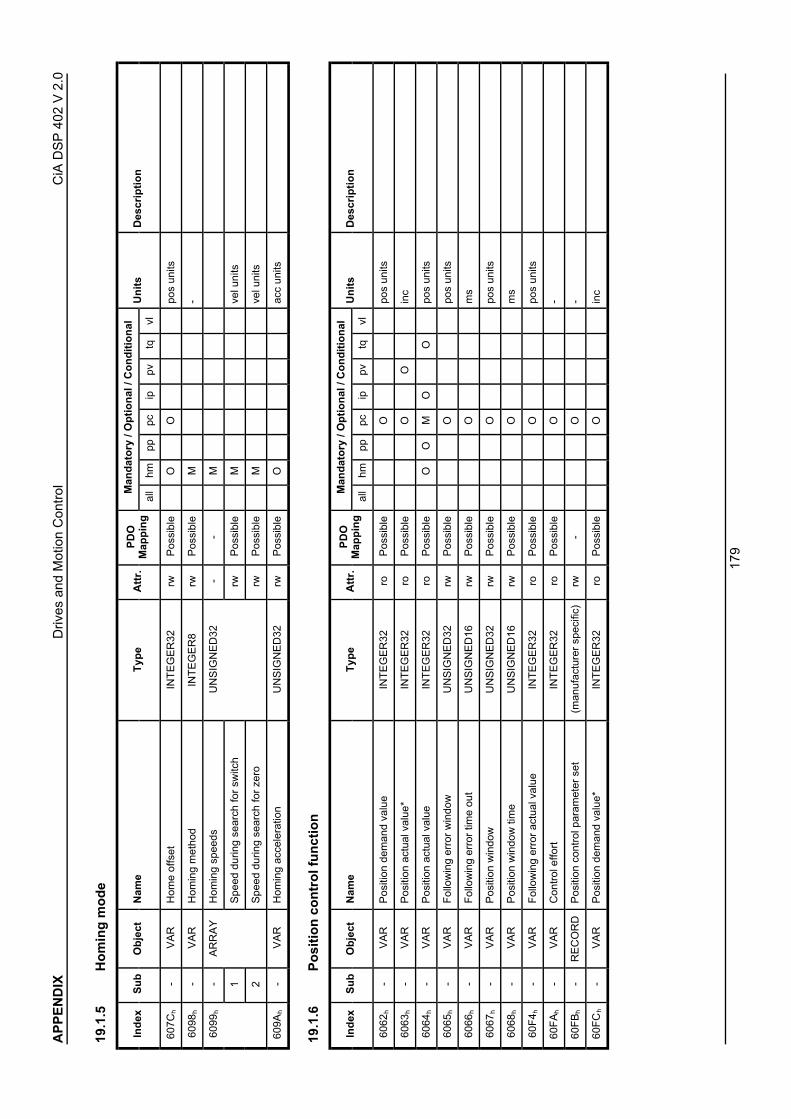
AP
PE
ND
IXD
rives
and
Mot
ion
Con
trol
CiA
DS
P 4
02 V
2.0
179
19.1
.5 H
om
ing
mo
de
Man
dat
ory
/ O
pti
on
al /
Co
nd
itio
nal
Ind
exS
ub
Ob
ject
Nam
eT
ype
Att
r.P
DO
Map
pin
gal
lhm
pppc
ippv
tqvl
Un
its
Des
crip
tio
n
607C
h-
VA
RH
ome
offs
etIN
TE
GE
R32
rwP
ossi
ble
OO
pos
units
6098
h-
VA
RH
omin
g m
etho
dIN
TE
GE
R8
rwP
ossi
ble
M-
-H
omin
g sp
eeds
--
M
1S
peed
dur
ing
sear
ch fo
r sw
itch
rwP
ossi
ble
Mve
l uni
ts
6099
h
2
AR
RA
Y
Spe
ed d
urin
g se
arch
for
zero
UN
SIG
NE
D32
rwP
ossi
ble
Mve
l uni
ts
609A
h-
VA
RH
omin
g ac
cele
ratio
nU
NS
IGN
ED
32rw
Pos
sibl
eO
acc
units
19.1
.6 P
osi
tio
n c
on
tro
l fu
nct
ion
Man
dat
ory
/ O
pti
on
al /
Co
nd
itio
nal
Ind
exS
ub
Ob
ject
Nam
eT
ype
Att
r.P
DO
Map
pin
gal
lhm
pppc
ippv
tqvl
Un
its
Des
crip
tio
n
6062
h-
VA
RP
ositi
on d
eman
d va
lue
INT
EG
ER
32ro
Pos
sibl
eO
pos
units
6063
h-
VA
RP
ositi
on a
ctua
l val
ue*
INT
EG
ER
32ro
Pos
sibl
eO
Oin
c
6064
h-
VA
RP
ositi
on a
ctua
l val
ueIN
TE
GE
R32
roP
ossi
ble
OO
MO
Opo
s un
its
6065
h-
VA
RF
ollo
win
g er
ror
win
dow
UN
SIG
NE
D32
rwP
ossi
ble
Opo
s un
its
6066
h-
VA
RF
ollo
win
g er
ror
time
out
UN
SIG
NE
D16
rwP
ossi
ble
Om
s
6067
h-
VA
RP
ositi
on w
indo
wU
NS
IGN
ED
32rw
Pos
sibl
eO
pos
units
6068
h-
VA
RP
ositi
on w
indo
w ti
me
UN
SIG
NE
D16
rwP
ossi
ble
Om
s
60F
4 h-
VA
RF
ollo
win
g er
ror
actu
al v
alue
INT
EG
ER
32ro
Pos
sibl
eO
pos
units
60F
Ah
-V
AR
Con
trol
effo
rtIN
TE
GE
R32
roP
ossi
ble
O-
60F
Bh
-R
EC
OR
DP
ositi
on c
ontr
ol p
aram
eter
set
(man
ufac
ture
r sp
ecifi
c)rw
-O
-
60F
Ch
-V
AR
Pos
ition
dem
and
valu
e*IN
TE
GE
R32
roP
ossi
ble
Oin
c

AP
PE
ND
IXD
rives
and
Mot
ion
Con
trol
CiA
DS
P 4
02 V
2.0
180
19.1
.7 In
terp
ola
ted
po
siti
on
mo
de
Man
dat
ory
/ O
pti
on
al /
Co
nd
itio
nal
Ind
exS
ub
Ob
ject
Nam
eT
ype
Att
r.P
DO
Map
pin
gal
lhm
pppc
ippv
tqvl
Un
its
Des
crip
tio
n
60C
0 h-
VA
RIn
terp
olat
ion
sub
mod
e se
lect
INT
EG
ER
16rw
Pos
sibl
eO
-
-In
terp
olat
ion
data
rec
ord
--
O-
1x 1
rwP
ossi
ble
M-
2X
2rw
Pos
sibl
eO
-
::::::
:::::
:::::
:::
60C
1 h
N
AR
RA
Y
x N
(see
60C
0h)
rwP
ossi
ble
O-
-In
terp
olat
ion
time
perio
dIn
terp
olat
ion
time
perio
d re
cord
--
O-
1ip
tim
e un
itsU
NS
IGN
ED
8rw
Pos
sibl
eM
10ip
tim
e in
dex s
60C
2 h
2
RE
CO
RD
ip ti
me
inde
xIN
TE
GE
R8
rwP
ossi
ble
M-
-In
terp
olat
ion
sync
def
initi
on-
-O
-
1S
ynch
roni
ze o
n gr
oup
rwP
ossi
ble
M-
60C
3 h
2
AR
RA
Y
ip s
ync
ever
y n
even
t
UN
SIG
NE
D8
rwP
ossi
ble
Mco
unts
-In
terp
olat
ion
data
con
figur
atio
nIn
terp
olat
ion
data
conf
igur
atio
n re
cord
--
O-
1M
axim
um b
uffe
r si
zeU
NS
IGN
ED
32ro
Pos
sibl
eM
-
2A
ctua
l buf
fer
size
UN
SIG
NE
D32
rwP
ossi
ble
M-
3B
uffe
r or
gani
zatio
nU
NS
IGN
ED
8rw
Pos
sibl
eM
-
4B
uffe
r po
sitio
nU
NS
IGN
ED
16rw
Pos
sibl
eM
-
5S
ize
of d
ata
reco
rdU
NS
IGN
ED
8w
oP
ossi
ble
M-
60C
4 h
6
RE
CO
RD
Buf
fer
clea
rU
NS
IGN
ED
8w
oP
ossi
ble
M-

AP
PE
ND
IXD
rives
and
Mot
ion
Con
trol
CiA
DS
P 4
02 V
2.0
181
19.1
.8 P
rofi
le v
elo
city
mo
de
Man
dat
ory
/ O
pti
on
al /
Co
nd
itio
nal
Ind
exS
ub
Ob
ject
Nam
eT
ype
Att
r.P
DO
Map
pin
gal
lhm
pppc
ippv
tqvl
Un
its
Des
crip
tio
n
6069
h-
VA
RV
eloc
ity s
enso
r ac
tual
val
ueIN
TE
GE
R32
roP
ossi
ble
Min
c / s
606A
h-
VA
RS
enso
r se
lect
ion
code
INT
EG
ER
16rw
Pos
sibl
eO
-
606B
h-
VA
RV
eloc
ity d
eman
d va
lue
INT
EG
ER
32ro
Pos
sibl
eM
vel u
nits
606C
h-
VA
RV
eloc
ity a
ctua
l val
ueIN
TE
GE
R32
roP
ossi
ble
Mve
l uni
ts
606D
h-
VA
RV
eloc
ity w
indo
wU
NS
IGN
ED
16rw
Pos
sibl
eO
vel u
nits
606E
h-
VA
RV
eloc
ity w
indo
w ti
me
UN
SIG
NE
D16
rwP
ossi
ble
Om
s
606F
h-
VA
RV
eloc
ity th
resh
old
UN
SIG
NE
D16
rwP
ossi
ble
Ove
l uni
ts
6070
h-
VA
RV
eloc
ity th
resh
old
time
UN
SIG
NE
D16
rwP
ossi
ble
Om
s
60F
Fh
-V
AR
Tar
get v
eloc
ityIN
TE
GE
R32
rwP
ossi
ble
Mve
l uni
ts
60F
8 h-
VA
RM
ax s
lippa
geIN
TE
GE
R32
roP
ossi
ble
Ove
l uni
ts
-V
eloc
ity c
ontr
ol p
aram
eter
set
--
O-
1G
ain
rwP
ossi
ble
M-
2T
I - in
tegr
atio
n tim
e co
nsta
ntrw
Pos
sibl
eM
-
3m
anuf
actu
rer
spec
ific
man
ufac
ture
rsp
ecifi
cO
-
::::::
:::::
:::::
-
60F
9 h
254
AR
RA
Y
man
ufac
ture
r sp
ecifi
c
UN
SIG
NE
D16
man
ufac
ture
rsp
ecifi
cO
-

AP
PE
ND
IXD
rives
and
Mot
ion
Con
trol
CiA
DS
P 4
02 V
2.0
182
19.1
.9 P
rofi
le t
orq
ue
mo
de
Man
dat
ory
/ O
pti
on
al /
Co
nd
itio
nal
Ind
exS
ub
Ob
ject
Nam
eT
ype
Att
r.P
DO
Map
pin
gal
lhm
pppc
ippv
tqvl
Un
its
Des
crip
tio
n
6071
h-
VA
RT
arge
t tor
que
INT
EG
ER
16rw
Pos
sibl
eO
Mpe
r th
ousa
ndof
rat
edto
rque
6072
h-
VA
RM
ax to
rque
UN
SIG
NE
D16
rwP
ossi
ble
oO
Ope
r th
ousa
ndof
rat
edto
rque
6073
h-
VA
RM
ax c
urre
ntU
NS
IGN
ED
16rw
Pos
sibl
eo
Ope
r th
ousa
ndof
rat
edcu
rren
t
6074
h-
VA
RT
orqu
e de
man
d va
lue
INT
EG
ER
16ro
Pos
sibl
eo
Ope
r th
ousa
ndof
rat
edto
rque
6075
h-
VA
RM
otor
rat
ed c
urre
ntU
NS
IGN
ED
32rw
Pos
sibl
eo
Om
A
6076
h-
VA
RM
otor
rat
ed to
rque
UN
SIG
NE
D32
rwP
ossi
ble
oO
0.00
1 N
m
6077
h-
VA
RT
orqu
e ac
tual
val
ueIN
TE
GE
R16
roP
ossi
ble
oO
per
thou
sand
of r
ated
torq
ue
6078
h-
VA
RC
urre
nt a
ctua
l val
ueIN
TE
GE
R16
roP
ossi
ble
oO
per
thou
sand
of r
ated
curr
ent
6079
h-
VA
RD
C li
nk c
ircui
t vol
tage
UN
SIG
NE
D32
roP
ossi
ble
Om
V
6087
h-
VA
RT
orqu
e sl
ope
UN
SIG
NE
D32
rwP
ossi
ble
Mpe
r th
ousa
ndof
rat
edto
rque
per
seco
nd
6088
h-
VA
RT
orqu
e pr
ofile
type
INT
EG
ER
16rw
Pos
sibl
eM
-
-P
ower
sta
ge p
aram
eter
s-
-O
-
1m
anuf
actu
rer
spec
ific
man
ufac
ture
r sp
ecifi
c-
::::::
:::::
::-
60F
7 h
254
RE
CO
RD
man
ufac
ture
r sp
ecifi
c
(man
ufac
ture
r sp
ecifi
c)
man
ufac
ture
r sp
ecifi
c-

AP
PE
ND
IXD
rives
and
Mot
ion
Con
trol
CiA
DS
P 4
02 V
2.0
183
Man
dat
ory
/ O
pti
on
al /
Co
nd
itio
nal
Ind
exS
ub
Ob
ject
Nam
eT
ype
Att
r.P
DO
Map
pin
gal
lhm
pppc
ippv
tqvl
Un
its
Des
crip
tio
n
-T
orqu
e co
ntro
l par
amet
ers
--
O-
1m
anuf
actu
rer
spec
ific
man
ufac
ture
r sp
ecifi
c-
::::::
:::::
::-
60F
6 h
254
RE
CO
RD
man
ufac
ture
r sp
ecifi
c
(man
ufac
ture
r sp
ecifi
c)
man
ufac
ture
r sp
ecifi
c-
19.1
.10
Vel
oci
ty m
od
e
Man
dat
ory
/ O
pti
on
al /
Co
nd
itio
nal
Ind
exS
ub
Ob
ject
Nam
eT
ype
Att
r.P
DO
Map
pin
gal
lhm
pppc
ippv
tqvl
Un
its
Des
crip
tio
n
6042
h-
VA
Rvl
targ
et v
eloc
ityIN
TE
GE
R16
rwP
ossi
ble
Mrp
m
6043
h-
VA
Rvl
vel
ocity
dem
and
INT
EG
ER
16ro
Pos
sibl
eM
rpm
6044
h-
VA
Rvl
con
trol
effo
rtIN
TE
GE
R16
roP
ossi
ble
Mrp
m
6045
h-
VA
Rvl
man
ipul
ated
vel
ocity
INT
EG
ER
16ro
Pos
sibl
eO
rpm
-vl
vel
ocity
min
max
am
ount
--
M-
1vl
vel
ocity
min
am
ount
rwP
ossi
ble
M-
6046
h
2
AR
RA
Y
vl v
eloc
ity m
ax a
mou
nt
UN
SIG
NE
D32
rwP
ossi
ble
M-
-vl
vel
ocity
min
max
--
O-
1vl
vel
ocity
min
pos
rwP
ossi
ble
M-
2vl
vel
ocity
max
pos
rwP
ossi
ble
M -
3vl
vel
ocity
min
neg
rwP
ossi
ble
M-
6047
h
4
AR
RA
Y
vl v
eloc
ity m
ax n
eg
UN
SIG
NE
D32
rwP
ossi
ble
M-
-vl
vel
ocity
acc
eler
atio
nvl
vel
ocity
acc
eler
atio
nde
cele
ratio
n re
cord
rw-
M-
1D
elta
spe
edU
NS
IGN
ED
32rw
Pos
sibl
eM
rpm
6048
h
2
RE
CO
RD
Del
ta ti
me
UN
SIG
NE
D16
rwP
ossi
ble
Ms

AP
PE
ND
IXD
rives
and
Mot
ion
Con
trol
CiA
DS
P 4
02 V
2.0
184
Man
dat
ory
/ O
pti
on
al /
Co
nd
itio
nal
Ind
exS
ub
Ob
ject
Nam
eT
ype
Att
r.P
DO
Map
pin
gal
lhm
pppc
ippv
tqvl
Un
its
Des
crip
tio
n
-vl
vel
ocity
dec
eler
atio
nvl
vel
ocity
acc
eler
atio
nde
cele
ratio
n re
cord
rw-
M-
1D
elta
spe
edU
NS
IGN
ED
23rw
Pos
sibl
eM
rpm
6049
h
2
RE
CO
RD
Del
ta ti
me
UN
SIG
NE
D16
rwP
ossi
ble
Ms
-vl
vel
ocity
qui
ck s
top
vl v
eloc
ity a
ccel
erat
ion
dece
lera
tion
reco
rdrw
-O
-
1D
elta
spe
edU
NS
IGN
ED
32rw
Pos
sibl
eM
rpm
604A
h
2
RE
CO
RD
Del
ta ti
me
UN
SIG
NE
D16
rwP
ossi
ble
Ms
-vl
set
-poi
nt fa
ctor
rw-
O-
1vl
set
-poi
nt fa
ctor
num
erat
orrw
Pos
sibl
eM
-
604B
h
2
AR
RA
Y
vl s
et-p
oint
fact
or d
enom
inat
or
INT
EG
ER
16
rwP
ossi
ble
M-
-vl
dim
ensi
on fa
ctor
--
O-
1vl
dim
ensi
on fa
ctor
num
erat
orrw
Pos
sibl
eM
-
604C
h
2
AR
RA
Y
vl d
imen
sion
fact
or d
enom
inat
or
INT
EG
ER
32
rwP
ossi
ble
M-
604D
h-
VA
Rvl
pol
e nu
mbe
rU
NS
IGN
ED
8rw
Pos
sibl
eO
-
604E
h-
VA
Rvl
vel
ocity
ref
eren
ceU
NS
IGN
ED
32rw
Pos
sibl
eO
rpm
604F
h-
VA
Rvl
ram
p fu
nctio
n tim
eU
NS
IGN
ED
32rw
Pos
sibl
eO
ms
6050
h-
VA
Rvl
slo
w d
own
time
UN
SIG
NE
D32
rwP
ossi
ble
Om
s
6051
h-
VA
Rvl
qui
ck s
top
time
UN
SIG
NE
D32
rwP
ossi
ble
Om
s
6052
h-
VA
Rvl
nom
inal
per
cent
age
INT
EG
ER
16rw
Pos
sibl
eO
-
6053
h-
VA
Rvl
per
cent
age
dem
and
INT
EG
ER
16ro
Pos
sibl
eO
-
6054
h-
VA
Rvl
act
ual p
erce
ntag
eIN
TE
GE
R16
roP
ossi
ble
O-
6055
h-
VA
Rvl
man
ipul
ated
per
cent
age
INT
EG
ER
16ro
Pos
sibl
eO
-
-vl
vel
ocity
mot
or m
in m
ax a
mou
nt-
-O
-
1vl
vel
ocity
mot
or m
in a
mou
ntrw
Pos
sibl
eM
(1/1
000)
rpm
6056
h
2
AR
RA
Y
vl v
eloc
ity m
otor
max
am
ount
UN
SIG
NE
D32
rwP
ossi
ble
M(1
/100
0) r
pm

AP
PE
ND
IXD
rives
and
Mot
ion
Con
trol
CiA
DS
P 4
02 V
2.0
185
Man
dat
ory
/ O
pti
on
al /
Co
nd
itio
nal
Ind
exS
ub
Ob
ject
Nam
eT
ype
Att
r.P
DO
Map
pin
gal
lhm
pppc
ippv
tqvl
Un
its
Des
crip
tio
n
-vl
vel
ocity
mot
or m
in m
ax-
-O
-
1vl
vel
ocity
mot
or m
in p
osrw
Pos
sibl
eM
(1/1
000)
rpm
2vl
vel
ocity
mot
or m
ax p
osrw
Pos
sibl
eM
(1/1
000)
rpm
3vl
vel
ocity
mot
or m
in n
egrw
Pos
sibl
eM
(1/1
000)
rpm
6057
h
4
AR
RA
Y
vl v
eloc
ity m
otor
max
neg
UN
SIG
NE
D32
rwP
ossi
ble
M(1
/100
0) r
pm
-vl
freq
uenc
y m
otor
min
max
am
ount
--
O-
1vl
freq
uenc
y m
otor
min
am
ount
rwP
ossi
ble
M-
6058
h
2
AR
RA
Y
vl fr
eque
ncy
mot
or m
ax a
mou
nt
UN
SIG
NE
D32
rwP
ossi
ble
M-
-vl
freq
uenc
y m
otor
min
max
--
O-
1vl
freq
uenc
y m
otor
min
pos
rwP
ossi
ble
M-
2vl
freq
uenc
y m
otor
max
pos
rwP
ossi
ble
M-
3vl
freq
uenc
y m
otor
min
neg
rwP
ossi
ble
M-
6059
h
4
AR
RA
Y
vl fr
eque
ncy
mot
or m
ax n
eg
UN
SIG
NE
D32
rwP
ossi
ble
M-

AP
PE
ND
IXD
rives
and
Mot
ion
Con
trol
CiA
DS
P 4
02 V
2.0
186
19.2
O
bje
ct d
icti
on
ary
by
ind
ex
Man
dat
ory
/ O
pti
on
al /
Co
nd
itio
nal
Ind
exS
ub
Ob
ject
Nam
eT
ype
Att
r.P
DO
Map
pin
gal
lhm
pppc
ippv
tqvl
Un
its
Des
crip
tio
n
6007
h-
VA
RA
bort
con
nect
ion
optio
n co
deIN
TE
GE
R16
rwP
ossi
ble
O-
603F
h-
VA
RE
rror
cod
eU
NS
IGN
ED
16ro
Pos
sibl
eO
-
6040
h-
VA
RC
ontr
olw
ord
UN
SIG
NE
D16
rwP
ossi
ble
M-
6041
h-
VA
RS
tatu
swor
dU
NS
IGN
ED
16ro
Pos
sibl
eM
-
6042
h-
VA
Rvl
targ
et v
eloc
ityIN
TE
GE
R16
rwP
ossi
ble
Mrp
m
6043
h-
VA
Rvl
vel
ocity
dem
and
INT
EG
ER
16ro
Pos
sibl
eM
rpm
6044
h-
VA
Rvl
con
trol
effo
rtIN
TE
GE
R16
roP
ossi
ble
Mrp
m
6045
h-
VA
Rvl
man
ipul
ated
vel
ocity
INT
EG
ER
16ro
Pos
sibl
eO
rpm
6046
h-
AR
RA
Yvl
vel
ocity
min
max
am
ount
UN
SIG
NE
D32
rw-
M-
6047
h-
AR
RA
Yvl
vel
ocity
min
max
UN
SIG
NE
D32
rw-
O-
6048
h-
RE
CO
RD
vl v
eloc
ity a
ccel
erat
ion
vl v
eloc
ity a
ccel
erat
ion
dece
lera
tion
reco
rdrw
-M
-
6049
h-
RE
CO
RD
vl v
eloc
ity d
ecel
erat
ion
vl v
eloc
ity a
ccel
erat
ion
dece
lera
tion
reco
rdrw
-M
-
604A
h-
RE
CO
RD
vl v
eloc
ity q
uick
sto
pvl
vel
ocity
acc
eler
atio
nde
cele
ratio
n re
cord
rw-
O-
604B
h-
AR
RA
Yvl
set
-poi
nt fa
ctor
INT
EG
ER
16rw
-O
-
604C
h-
AR
RA
Yvl
dim
ensi
on fa
ctor
INT
EG
ER
32rw
-O
-
604D
h-
VA
Rvl
pol
e nu
mbe
rU
NS
IGN
ED
8rw
Pos
sibl
eO
-
604E
h-
VA
Rvl
vel
ocity
ref
eren
ceU
NS
IGN
ED
32rw
Pos
sibl
eO
rpm
604F
h-
VA
Rvl
ram
p fu
nctio
n tim
eU
NS
IGN
ED
32rw
Pos
sibl
eO
ms
6050
h-
VA
Rvl
slo
w d
own
time
UN
SIG
NE
D32
rwP
ossi
ble
Om
s
6051
h-
VA
Rvl
qui
ck s
top
time
UN
SIG
NE
D32
rwP
ossi
ble
Om
s
6052
h-
VA
Rvl
nom
inal
per
cent
age
INT
EG
ER
16rw
Pos
sibl
eO
-
6053
h-
VA
Rvl
per
cent
age
dem
and
INT
EG
ER
16ro
Pos
sibl
eO
-
6054
h-
VA
Rvl
act
ual p
erce
ntag
eIN
TE
GE
R16
roP
ossi
ble
O-

AP
PE
ND
IXD
rives
and
Mot
ion
Con
trol
CiA
DS
P 4
02 V
2.0
187
Man
dat
ory
/ O
pti
on
al /
Co
nd
itio
nal
Ind
exS
ub
Ob
ject
Nam
eT
ype
Att
r.P
DO
Map
pin
gal
lhm
pppc
ippv
tqvl
Un
its
Des
crip
tio
n
6055
h-
VA
Rvl
man
ipul
ated
per
cent
age
INT
EG
ER
16ro
Pos
sibl
eO
-
6056
h-
AR
RA
Yvl
vel
ocity
mot
or m
in m
ax a
mou
ntU
NS
IGN
ED
32rw
-O
(1/1
000)
rpm
6057
h-
AR
RA
Yvl
vel
ocity
mot
or m
in m
axU
NS
IGN
ED
32rw
-O
(1/1
000)
rpm
6058
h-
AR
RA
Yvl
freq
uenc
y m
otor
min
max
am
ount
UN
SIG
NE
D32
rw-
O-
6059
h-
AR
RA
Yvl
freq
uenc
y m
otor
min
max
UN
SIG
NE
D32
rw-
O-
605A
h-
VA
RQ
uick
sto
p op
tion
code
INT
EG
ER
16rw
No
O-
605B
h-
VA
RS
hutd
own
optio
n co
deIN
TE
GE
R16
rwN
oO
-
605C
h-
VA
RD
isab
le o
pera
tion
optio
n co
deIN
TE
GE
R16
rwN
oO
-
605D
h-
VA
RH
alt o
ptio
n co
deIN
TE
GE
R16
rwN
oO
-
605E
h-
VA
RF
ault
reac
tion
optio
n co
deIN
TE
GE
R16
rwN
oO
-
6060
h-
VA
RM
odes
of o
pera
tion
INT
EG
ER
8rw
Pos
sibl
eM
-
6061
h-
VA
RM
odes
of o
pera
tion
disp
lay
INT
EG
ER
8ro
Pos
sibl
eM
-
6062
h-
VA
RP
ositi
on d
eman
d va
lue
INT
EG
ER
32ro
Pos
sibl
eO
pos
units
6063
h-
VA
RP
ositi
on a
ctua
l val
ue*
INT
EG
ER
32ro
Pos
sibl
eO
Oin
c
6064
h-
VA
RP
ositi
on a
ctua
l val
ueIN
TE
GE
R32
roP
ossi
ble
OO
MO
Opo
s un
its
6065
h-
VA
RF
ollo
win
g er
ror
win
dow
UN
SIG
NE
D32
rwP
ossi
ble
Opo
s un
its
6066
h-
VA
RF
ollo
win
g er
ror
time
out
UN
SIG
NE
D16
rwP
ossi
ble
Om
s
6067
h-
VA
RP
ositi
on w
indo
wU
NS
IGN
ED
32rw
Pos
sibl
eO
pos
units
6068
h-
VA
RP
ositi
on w
indo
w ti
me
UN
SIG
NE
D16
rwP
ossi
ble
Om
s
6069
h-
VA
RV
eloc
ity s
enso
r ac
tual
val
ueIN
TE
GE
R32
roP
ossi
ble
Min
c / s
606A
h-
VA
RS
enso
r se
lect
ion
code
INT
EG
ER
16rw
Pos
sibl
eO
-
606B
h-
VA
RV
eloc
ity d
eman
d va
lue
INT
EG
ER
32ro
Pos
sibl
eM
vel u
nits
606C
h-
VA
RV
eloc
ity a
ctua
l val
ueIN
TE
GE
R32
roP
ossi
ble
Mve
l uni
ts
606D
h-
VA
RV
eloc
ity w
indo
wU
NS
IGN
ED
16rw
Pos
sibl
eO
vel u
nits
606E
h-
VA
RV
eloc
ity w
indo
w ti
me
UN
SIG
NE
D16
rwP
ossi
ble
Om
s
606F
h-
VA
RV
eloc
ity th
resh
old
UN
SIG
NE
D16
rwP
ossi
ble
Ove
l uni
ts

AP
PE
ND
IXD
rives
and
Mot
ion
Con
trol
CiA
DS
P 4
02 V
2.0
188
Man
dat
ory
/ O
pti
on
al /
Co
nd
itio
nal
Ind
exS
ub
Ob
ject
Nam
eT
ype
Att
r.P
DO
Map
pin
gal
lhm
pppc
ippv
tqvl
Un
its
Des
crip
tio
n
6070
h-
VA
RV
eloc
ity th
resh
old
time
UN
SIG
NE
D16
r/w
Pos
sibl
eO
ms
6071
h-
VA
RT
arge
t tor
que
INT
EG
ER
16rw
Pos
sibl
eO
Mpe
r th
ousa
ndof
rat
edto
rque
6072
h-
VA
RM
ax to
rque
UN
SIG
NE
D16
rwP
ossi
ble
OO
per
thou
sand
of r
ated
torq
ue
6073
h-
VA
RM
ax c
urre
ntU
NS
IGN
ED
16rw
Pos
sibl
eO
per
thou
sand
of r
ated
curr
ent
6074
h-
VA
RT
orqu
e de
man
d va
lue
INT
EG
ER
16ro
Pos
sibl
eO
per
thou
sand
of r
ated
torq
ue
6075
h-
VA
RM
otor
rat
ed c
urre
ntU
NS
IGN
ED
32rw
Pos
sibl
eO
mA
6076
h-
VA
RM
otor
rat
ed to
rque
UN
SIG
NE
D32
rwP
ossi
ble
O0.
001
Nm
6077
h-
VA
RT
orqu
e ac
tual
val
ueIN
TE
GE
R16
roP
ossi
ble
Ope
r th
ousa
ndof
rat
edto
rque
6078
h-
VA
RC
urre
nt a
ctua
l val
ueIN
TE
GE
R16
roP
ossi
ble
Ope
r th
ousa
ndof
rat
edcu
rren
t
6079
h-
VA
RD
C li
nk c
ircui
t vol
tage
UN
SIG
NE
D32
roP
ossi
ble
Om
V
607A
h-
VA
RT
arge
t pos
ition
INT
EG
ER
32rw
Pos
sibl
eM
Mpo
s un
its
607B
h-
AR
RA
YP
ositi
on r
ange
lim
itIN
TE
GE
R32
rw-
OO
-
607C
h-
VA
RH
ome
offs
etIN
TE
GE
R32
rwP
ossi
ble
OO
pos
units
607D
h-
AR
RA
YS
oftw
are
posi
tion
limit
INT
EG
ER
32rw
-O
Opo
s un
its
607E
h-
VA
RP
olar
ityU
NS
IGN
ED
8rw
Pos
sibl
eO
OO
OO
-
607F
h-
VA
RM
ax p
rofil
e ve
loci
tyU
NS
IGN
ED
32rw
Pos
sibl
eO
Osp
eed
units
6080
h-
VA
RM
ax m
otor
spe
edU
NS
IGN
ED
32rw
Pos
sibl
eO
Orp
m
6081
h-
VA
RP
rofil
e ve
loci
tyU
NS
IGN
ED
32rw
Pos
sibl
eM
Msp
eed
units
6082
h-
VA
RE
nd v
eloc
ityU
NS
IGN
ED
32rw
Pos
sibl
eO
spee
d un
its

AP
PE
ND
IXD
rives
and
Mot
ion
Con
trol
CiA
DS
P 4
02 V
2.0
189
Man
dat
ory
/ O
pti
on
al /
Co
nd
itio
nal
Ind
exS
ub
Ob
ject
Nam
eT
ype
Att
r.P
DO
Map
pin
gal
lhm
pppc
ippv
tqvl
Un
its
Des
crip
tio
n
6083
h-
VA
RP
rofil
e ac
cele
ratio
nU
NS
IGN
ED
32rw
Pos
sibl
eM
Mac
c un
its
6084
h-
VA
RP
rofil
e de
cele
ratio
nU
NS
IGN
ED
32rw
Pos
sibl
eM
Mac
c un
its
6085
h-
VA
RQ
uick
sto
p de
cele
ratio
nU
NS
IGN
ED
32rw
Pos
sibl
eO
Oac
c un
its
6086
h-
VA
RM
otio
n pr
ofile
type
INT
EG
ER
16rw
Pos
sibl
eM
M-
6087
h-
VA
RT
orqu
e sl
ope
UN
SIG
NE
D32
rwP
ossi
ble
Mpe
r th
ousa
ndof
rat
edto
rque
per
seco
nd
6088
h-
VA
RT
orqu
e pr
ofile
type
INT
EG
ER
16rw
Pos
sibl
eM
-
6089
h-
VA
RP
ositi
on n
otat
ion
inde
xIN
TE
GE
R8
rwP
ossi
ble
CC
CC
C-
608A
h-
VA
RP
ositi
on d
imen
sion
inde
xU
NS
IGN
ED
8rw
Pos
sibl
eC
CC
CC
-
608B
h-
VA
RV
eloc
ity n
otat
ion
inde
xIN
TE
GE
R8
rwP
ossi
ble
CC
CC
C-
608C
h-
VA
RV
eloc
ity d
imen
sion
inde
xU
NS
IGN
ED
8rw
Pos
sibl
eC
CC
CC
-
608D
h-
VA
RA
ccel
erat
ion
nota
tion
inde
xIN
TE
GE
R8
rwP
ossi
ble
CC
CC
C-
608E
h-
VA
RA
ccel
erat
ion
dim
ensi
on in
dex
UN
SIG
NE
D8
rwP
ossi
ble
CC
CC
C-
608F
h-
AR
RA
YP
ositi
on e
ncod
er r
esol
utio
nU
NS
IGN
ED
32rw
-O
OO
Oin
c / r
ev
6090
h-
AR
RA
YV
eloc
ity e
ncod
er r
esol
utio
nU
NS
IGN
ED
32rw
-O
OO
Oin
c / r
ev
6091
h-
AR
RA
YG
ear
ratio
UN
SIG
NE
D32
rw-
OO
OO
-
6092
h-
AR
RA
YF
eed
cons
tant
UN
SIG
NE
D32
rw-
OO
OO
pos
units
/ re
v
6093
h-
AR
RA
YP
ositi
on fa
ctor
UN
SIG
NE
D32
rw-
OO
O-
6094
h-
AR
RA
YV
eloc
ity e
ncod
er fa
ctor
UN
SIG
NE
D32
rw-
OO
O-
6095
h-
AR
RA
YV
eloc
ity fa
ctor
1U
NS
IGN
ED
32rw
-O
OO
OO
-
6096
h-
AR
RA
YV
eloc
ity fa
ctor
2U
NS
IGN
ED
32rw
-O
OO
O-
6097
h-
AR
RA
YA
ccel
erat
ion
fact
orU
NS
IGN
ED
32rw
-O
OO
OO
-
6098
h-
VA
RH
omin
g m
etho
dIN
TE
GE
R8
rwP
ossi
ble
M-
6099
h-
AR
RA
YH
omin
g sp
eeds
UN
SIG
NE
D32
rw-
Mve
l uni
ts
609A
h-
VA
RH
omin
g ac
cele
ratio
nU
NS
IGN
ED
32rw
Pos
sibl
eO
acc
units

AP
PE
ND
IXD
rives
and
Mot
ion
Con
trol
CiA
DS
P 4
02 V
2.0
190
Man
dat
ory
/ O
pti
on
al /
Co
nd
itio
nal
Ind
exS
ub
Ob
ject
Nam
eT
ype
Att
r.P
DO
Map
pin
gal
lhm
pppc
ippv
tqvl
Un
its
Des
crip
tio
n
60C
0 h-
VA
RIn
terp
olat
ion
sub
mod
e se
lect
INT
EG
ER
16rw
Pos
sibl
eO
-
60C
1 h-
AR
RA
YIn
terp
olat
ion
data
rec
ord
(see
60C
0h)
rw-
O-
60C
2 h-
RE
CO
RD
Inte
rpol
atio
n tim
e pe
riod
Inte
rpol
atio
n tim
epe
riod
reco
rdrw
-O
-
60C
3 h-
AR
RA
YIn
terp
olat
ion
sync
def
initi
onU
NS
IGN
ED
8rw
-O
-
60C
4 h-
RE
CO
RD
Inte
rpol
atio
n da
ta c
onfig
urat
ion
Inte
rpol
atio
n da
taco
nfig
urat
ion
reco
rd-
-O
-
60C
5 h-
VA
RM
ax a
ccel
erat
ion
UN
SIG
NE
D32
rwP
ossi
ble
Oac
c un
its
60C
6 h-
VA
RM
ax d
ecel
erat
ion
UN
SIG
NE
D32
rwP
ossi
ble
Oac
c un
its
60F
4 h-
VA
RF
ollo
win
g er
ror
actu
al v
alue
INT
EG
ER
32ro
Pos
sibl
eO
pos
units
60F
6 h-
RE
CO
RD
Tor
que
cont
rol p
aram
eter
s(m
anuf
actu
rer
spec
ific)
--
O-
60F
7 h-
RE
CO
RD
Pow
er s
tage
par
amet
ers
(man
ufac
ture
r sp
ecifi
c)-
-O
-
60F
8 h-
VA
RM
ax s
lippa
geIN
TE
GE
R32
roP
ossi
ble
Ove
l uni
ts
60F
9 h-
AR
RA
YV
eloc
ity c
ontr
ol p
aram
eter
set
UN
SIG
NE
D16
rw-
O-
60F
Ah
-V
AR
Con
trol
effo
rtIN
TE
GE
R32
roP
ossi
ble
O-
60F
Bh
-R
EC
OR
DP
ositi
on c
ontr
ol p
aram
eter
set
(man
ufac
ture
r sp
ecifi
c)-
-O
-
60F
Ch
-V
AR
Pos
ition
dem
and
valu
e*IN
TE
GE
R32
roP
ossi
ble
Oin
c
60F
Dh
-V
AR
Dig
ital i
nput
sU
NS
IGN
ED
32ro
Pos
sibl
eO
-
60F
Eh
-A
RR
AY
Dig
ital o
utpu
tsU
NS
IGN
ED
32rw
-O
-
60F
Fh
-V
AR
Tar
get v
eloc
ityIN
TE
GE
R32
rwP
ossi
ble
Mve
l uni
ts
6402
h-
VA
RM
otor
type
UN
SIG
NE
D16
rwP
ossi
ble
O-
6403
h-
VA
RM
otor
cat
alog
num
ber
VIS
IBLE
_ST
RIN
Grw
No
O-
6404
h-
VA
RM
otor
man
ufac
ture
rV
ISIB
LE_S
TR
ING
rwN
oO
-
6405
h-
VA
Rht
tp m
otor
cat
alog
add
ress
VIS
IBLE
_ST
RIN
Grw
No
O-
6406
h-
VA
RM
otor
cal
ibra
tion
date
TIM
E_O
F_D
AY
rwP
ossi
ble
O-
6407
h-
VA
RM
otor
ser
vice
per
iod
UN
SIG
NE
D32
rwP
ossi
ble
O-
6410
h-
RE
CO
RD
Mot
or d
ata
(man
ufac
ture
r sp
ecifi
c)rw
-O
-

AP
PE
ND
IXD
rives
and
Mot
ion
Con
trol
CiA
DS
P 4
02 V
2.0
191
Man
dat
ory
/ O
pti
on
al /
Co
nd
itio
nal
Ind
exS
ub
Ob
ject
Nam
eT
ype
Att
r.P
DO
Map
pin
gal
lhm
pppc
ippv
tqvl
Un
its
Des
crip
tio
n
6502
h-
VA
RS
uppo
rted
driv
e m
odes
UN
SIG
NE
D32
roP
ossi
ble
O-
6503
h-
VA
RD
rive
cata
log
num
ber
VIS
IBLE
_ST
RIN
Grw
No
O-
6504
h-
VA
RD
rive
man
ufac
ture
rV
ISIB
LE_S
TR
ING
rwN
oO
-
6505
h-
VA
Rht
tp d
rive
cata
log
addr
ess
VIS
IBLE
_ST
RIN
Grw
No
O-
6510
h-
RE
CO
RD
Driv
e da
ta(m
anuf
actu
rer
spec
ific)
--
O-

AP
PE
ND
IXD
rives
and
Mot
ion
Con
trol
CiA
DS
P 4
02 V
2.0
192
19.3
O
bje
ct d
icti
on
ary
by
nam
e
Man
dat
ory
/ O
pti
on
al /
Co
nd
itio
nal
Ind
exS
ub
Ob
ject
Nam
eT
ype
Att
r.P
DO
Map
pin
gal
lhm
pppc
ippv
tqvl
Un
its
Des
crip
tio
n
6007
h-
VA
RA
bort
con
nect
ion
optio
n co
deIN
TE
GE
R16
rwP
ossi
ble
O-
608E
h-
VA
RA
ccel
erat
ion
dim
ensi
on in
dex
UN
SIG
NE
D8
rwP
ossi
ble
CC
CC
C-
6097
h-
AR
RA
YA
ccel
erat
ion
fact
orU
NS
IGN
ED
32rw
-O
OO
OO
-
608D
h-
VA
RA
ccel
erat
ion
nota
tion
inde
xIN
TE
GE
R8
rwP
ossi
ble
CC
CC
C-
60F
Ah
-V
AR
Con
trol
effo
rtIN
TE
GE
R32
roP
ossi
ble
O-
6040
h-
VA
RC
ontr
olw
ord
UN
SIG
NE
D16
rwP
ossi
ble
M-
6078
h-
VA
RC
urre
nt a
ctua
l val
ueIN
TE
GE
R16
roP
ossi
ble
Ope
r th
ousa
ndof
rat
edcu
rren
t
6079
h-
VA
RD
C li
nk c
ircui
t vol
tage
UN
SIG
NE
D32
roP
ossi
ble
Om
V
60F
Dh
-V
AR
Dig
ital i
nput
sU
NS
IGN
ED
32ro
Pos
sibl
eO
-
60F
Eh
-A
RR
AY
Dig
ital o
utpu
tsU
NS
IGN
ED
32rw
-O
-
605C
h-
VA
RD
isab
le o
pera
tion
optio
n co
deIN
TE
GE
R16
rwN
oO
-
6503
h-
VA
RD
rive
cata
log
num
ber
VIS
IBLE
_ST
RIN
Grw
No
O-
6510
h-
RE
CO
RD
Driv
e da
ta(m
anuf
actu
rer
spec
ific)
--
O-
6504
h-
VA
RD
rive
man
ufac
ture
rV
ISIB
LE_S
TR
ING
rwN
oO
-
6082
h-
VA
RE
nd v
eloc
ityU
NS
IGN
ED
32rw
Pos
sibl
eO
spee
d un
its
603F
h-
VA
RE
rror
cod
eU
NS
IGN
ED
16ro
Pos
sibl
eO
-
605E
h-
VA
RF
ault
reac
tion
optio
n co
deIN
TE
GE
R16
rwN
oO
-
6092
h-
AR
RA
YF
eed
cons
tant
UN
SIG
NE
D32
rw-
OO
OO
pos
units
/ re
v
60F
4 h-
VA
RF
ollo
win
g er
ror
actu
al v
alue
INT
EG
ER
32ro
Pos
sibl
eO
pos
units
6066
h-
VA
RF
ollo
win
g er
ror
time
out
UN
SIG
NE
D16
rwP
ossi
ble
Om
s
6065
h-
VA
RF
ollo
win
g er
ror
win
dow
UN
SIG
NE
D32
rwP
ossi
ble
Opo
s un
its
6091
h-
AR
RA
YG
ear
ratio
UN
SIG
NE
D32
rw-
OO
OO
-
605D
h-
VA
RH
alt o
ptio
n co
deIN
TE
GE
R16
rwN
oO
-

AP
PE
ND
IXD
rives
and
Mot
ion
Con
trol
CiA
DS
P 4
02 V
2.0
193
Man
dat
ory
/ O
pti
on
al /
Co
nd
itio
nal
Ind
exS
ub
Ob
ject
Nam
eT
ype
Att
r.P
DO
Map
pin
gal
lhm
pppc
ippv
tqvl
Un
its
Des
crip
tio
n
607C
h-
VA
RH
ome
offs
etIN
TE
GE
R32
rwP
ossi
ble
OO
pos
units
609A
h-
VA
RH
omin
g ac
cele
ratio
nU
NS
IGN
ED
32rw
Pos
sibl
eO
acc
units
6098
h-
VA
RH
omin
g m
etho
dIN
TE
GE
R8
rwP
ossi
ble
M-
6099
h-
AR
RA
YH
omin
g sp
eeds
UN
SIG
NE
D32
rw-
Mve
l uni
ts
6505
h-
VA
Rht
tp d
rive
cata
log
addr
ess
VIS
IBLE
_ST
RIN
Grw
No
O-
6405
h-
VA
Rht
tp m
otor
cat
alog
add
ress
VIS
IBLE
_ST
RIN
Grw
No
O-
60C
4 h-
RE
CO
RD
Inte
rpol
atio
n da
ta c
onfig
urat
ion
Inte
rpol
atio
n da
taco
nfig
urat
ion
reco
rd-
-O
-
60C
1 h-
AR
RA
YIn
terp
olat
ion
data
rec
ord
(see
60C
0h)
rw-
O-
60C
0 h-
VA
RIn
terp
olat
ion
sub
mod
e se
lect
INT
EG
ER
16rw
Pos
sibl
eO
-
60C
3 h-
AR
RA
YIn
terp
olat
ion
sync
def
initi
onU
NS
IGN
ED
8rw
-O
-
60C
2 h-
RE
CO
RD
Inte
rpol
atio
n tim
e pe
riod
Inte
rpol
atio
n tim
epe
riod
reco
rdrw
-O
-
60C
5 h-
VA
RM
ax a
ccel
erat
ion
UN
SIG
NE
D32
rwP
ossi
ble
Oac
c un
its
6073
h-
VA
RM
ax c
urre
ntU
NS
IGN
ED
16rw
Pos
sibl
eO
per
thou
sand
of r
ated
curr
ent
60C
6 h-
VA
RM
ax d
ecel
erat
ion
UN
SIG
NE
D32
rwP
ossi
ble
Oac
c un
its
6080
h-
VA
RM
ax m
otor
spe
edU
NS
IGN
ED
32rw
Pos
sibl
eO
Orp
m
607F
h-
VA
RM
ax p
rofil
e ve
loci
tyU
NS
IGN
ED
32rw
Pos
sibl
eO
Osp
eed
units
60F
8 h-
VA
RM
ax s
lippa
geIN
TE
GE
R32
roP
ossi
ble
Ove
l uni
ts
6072
h-
VA
RM
ax to
rque
UN
SIG
NE
D16
rwP
ossi
ble
OO
per
thou
sand
of r
ated
torq
ue
6060
h-
VA
RM
odes
of o
pera
tion
INT
EG
ER
8rw
Pos
sibl
eM
-
6061
h-
VA
RM
odes
of o
pera
tion
disp
lay
INT
EG
ER
8ro
Pos
sibl
eM
-
6086
h-
VA
RM
otio
n pr
ofile
type
INT
EG
ER
16rw
Pos
sibl
eM
M-
6406
h-
VA
RM
otor
cal
ibra
tion
date
TIM
E_O
F_D
AY
rwP
ossi
ble
O-

AP
PE
ND
IXD
rives
and
Mot
ion
Con
trol
CiA
DS
P 4
02 V
2.0
194
Man
dat
ory
/ O
pti
on
al /
Co
nd
itio
nal
Ind
exS
ub
Ob
ject
Nam
eT
ype
Att
r.P
DO
Map
pin
gal
lhm
pppc
ippv
tqvl
Un
its
Des
crip
tio
n
6403
h-
VA
RM
otor
cat
alog
num
ber
VIS
IBLE
_ST
RIN
Grw
No
O-
6410
h-
RE
CO
RD
Mot
or d
ata
(man
ufac
ture
r sp
ecifi
c)rw
-O
-
6404
h-
VA
RM
otor
man
ufac
ture
rV
ISIB
LE_S
TR
ING
rwN
oO
-
6075
h-
VA
RM
otor
rat
ed c
urre
ntU
NS
IGN
ED
32rw
Pos
sibl
eO
mA
6076
h-
VA
RM
otor
rat
ed to
rque
UN
SIG
NE
D32
rwP
ossi
ble
O0.
001
Nm
6407
h-
VA
RM
otor
ser
vice
per
iod
UN
SIG
NE
D32
rwP
ossi
ble
O-
6402
h-
VA
RM
otor
type
UN
SIG
NE
D16
rwP
ossi
ble
O-
607E
h-
VA
RP
olar
ityU
NS
IGN
ED
8rw
Pos
sibl
eO
OO
OO
-
6064
h-
VA
RP
ositi
on a
ctua
l val
ueIN
TE
GE
R32
roP
ossi
ble
OO
MO
Opo
s un
its
6063
h-
VA
RP
ositi
on a
ctua
l val
ue*
INT
EG
ER
32ro
Pos
sibl
eO
Oin
c
60F
Bh
-R
EC
OR
DP
ositi
on c
ontr
ol p
aram
eter
set
(man
ufac
ture
r sp
ecifi
c)-
-O
-
6062
h-
VA
RP
ositi
on d
eman
d va
lue
INT
EG
ER
32ro
Pos
sibl
eO
pos
units
60F
Ch
-V
AR
Pos
ition
dem
and
valu
e*IN
TE
GE
R32
roP
ossi
ble
Oin
c
608A
h-
VA
RP
ositi
on d
imen
sion
inde
xU
NS
IGN
ED
8rw
Pos
sibl
eC
CC
CC
-
608F
h-
AR
RA
YP
ositi
on e
ncod
er r
esol
utio
nU
NS
IGN
ED
32rw
-O
OO
Oin
c / r
ev
6093
h-
AR
RA
YP
ositi
on fa
ctor
UN
SIG
NE
D32
rw-
OO
O-
6089
h-
VA
RP
ositi
on n
otat
ion
inde
xIN
TE
GE
R8
rwP
ossi
ble
CC
CC
C-
607B
h-
AR
RA
YP
ositi
on r
ange
lim
itIN
TE
GE
R32
rw-
OO
-
6067
h-
VA
RP
ositi
on w
indo
wU
NS
IGN
ED
32rw
Pos
sibl
eO
pos
units
6068
h-
VA
RP
ositi
on w
indo
w ti
me
UN
SIG
NE
D16
rwP
ossi
ble
Om
s
60F
7 h-
RE
CO
RD
Pow
er s
tage
par
amet
ers
(man
ufac
ture
r sp
ecifi
c)-
-O
-
6083
h-
VA
RP
rofil
e ac
cele
ratio
nU
NS
IGN
ED
32rw
Pos
sibl
eM
Mac
c un
its
6084
h-
VA
RP
rofil
e de
cele
ratio
nU
NS
IGN
ED
32rw
Pos
sibl
eM
Mac
c un
its
6081
h-
VA
RP
rofil
e ve
loci
tyU
NS
IGN
ED
32rw
Pos
sibl
eM
Msp
eed
units
6085
h-
VA
RQ
uick
sto
p de
cele
ratio
nU
NS
IGN
ED
32rw
Pos
sibl
eO
Oac
c un
its
605A
h-
VA
RQ
uick
sto
p op
tion
code
INT
EG
ER
16rw
No
O-

AP
PE
ND
IXD
rives
and
Mot
ion
Con
trol
CiA
DS
P 4
02 V
2.0
195
Man
dat
ory
/ O
pti
on
al /
Co
nd
itio
nal
Ind
exS
ub
Ob
ject
Nam
eT
ype
Att
r.P
DO
Map
pin
gal
lhm
pppc
ippv
tqvl
Un
its
Des
crip
tio
n
606A
h-
VA
RS
enso
r se
lect
ion
code
INT
EG
ER
16rw
Pos
sibl
eO
-
605B
h-
VA
RS
hutd
own
optio
n co
deIN
TE
GE
R16
rwN
oO
-
607D
h-
AR
RA
YS
oftw
are
posi
tion
limit
INT
EG
ER
32rw
-O
Opo
s un
its
6041
h-
VA
RS
tatu
swor
dU
NS
IGN
ED
16ro
Pos
sibl
eM
-
6502
h-
VA
RS
uppo
rted
driv
e m
odes
UN
SIG
NE
D32
roP
ossi
ble
O-
607A
h-
VA
RT
arge
t pos
ition
INT
EG
ER
32rw
Pos
sibl
eM
Mpo
s un
its
6071
h-
VA
RT
arge
t tor
que
INT
EG
ER
16rw
Pos
sibl
eO
Mpe
r th
ousa
ndof
rat
edto
rque
60F
Fh
-V
AR
Tar
get v
eloc
ityIN
TE
GE
R32
rwP
ossi
ble
Mve
l uni
ts
6077
h-
VA
RT
orqu
e ac
tual
val
ueIN
TE
GE
R16
roP
ossi
ble
Ope
r th
ousa
ndof
rat
edto
rque
60F
6 h-
RE
CO
RD
Tor
que
cont
rol p
aram
eter
s(m
anuf
actu
rer
spec
ific)
--
O-
6074
h-
VA
RT
orqu
e de
man
d va
lue
INT
EG
ER
16ro
Pos
sibl
eO
per
thou
sand
of r
ated
torq
ue
6088
h-
VA
RT
orqu
e pr
ofile
type
INT
EG
ER
16rw
Pos
sibl
eM
-
6087
h-
VA
RT
orqu
e sl
ope
UN
SIG
NE
D32
rwP
ossi
ble
Mpe
r th
ousa
ndof
rat
edto
rque
per
seco
nd
606C
h-
VA
RV
eloc
ity a
ctua
l val
ueIN
TE
GE
R32
roP
ossi
ble
Mve
l uni
ts
60F
9 h-
AR
RA
YV
eloc
ity c
ontr
ol p
aram
eter
set
UN
SIG
NE
D16
rw-
O-
606B
h-
VA
RV
eloc
ity d
eman
d va
lue
INT
EG
ER
32ro
Pos
sibl
eM
vel u
nits
608C
h-
VA
RV
eloc
ity d
imen
sion
inde
xU
NS
IGN
ED
8rw
Pos
sibl
eC
CC
CC
-
6094
h-
AR
RA
YV
eloc
ity e
ncod
er fa
ctor
UN
SIG
NE
D32
rw-
OO
O-
6090
h-
AR
RA
YV
eloc
ity e
ncod
er r
esol
utio
nU
NS
IGN
ED
32rw
-O
OO
Oin
c / r
ev
6095
h-
AR
RA
YV
eloc
ity fa
ctor
1U
NS
IGN
ED
32rw
-O
OO
OO
-
6096
h-
AR
RA
YV
eloc
ity fa
ctor
2U
NS
IGN
ED
32rw
-O
OO
O-

AP
PE
ND
IXD
rives
and
Mot
ion
Con
trol
CiA
DS
P 4
02 V
2.0
196
Man
dat
ory
/ O
pti
on
al /
Co
nd
itio
nal
Ind
exS
ub
Ob
ject
Nam
eT
ype
Att
r.P
DO
Map
pin
gal
lhm
pppc
ippv
tqvl
Un
its
Des
crip
tio
n
608B
h-
VA
RV
eloc
ity n
otat
ion
inde
xIN
TE
GE
R8
rwP
ossi
ble
CC
CC
C-
6069
h-
VA
RV
eloc
ity s
enso
r ac
tual
val
ueIN
TE
GE
R32
roP
ossi
ble
Min
c / s
606F
h-
VA
RV
eloc
ity th
resh
old
UN
SIG
NE
D16
rwP
ossi
ble
Ove
l uni
ts
6070
h-
VA
RV
eloc
ity th
resh
old
time
UN
SIG
NE
D16
r/w
Pos
sibl
eO
ms
606D
h-
VA
RV
eloc
ity w
indo
wU
NS
IGN
ED
16rw
Pos
sibl
eO
vel u
nits
606E
h-
VA
RV
eloc
ity w
indo
w ti
me
UN
SIG
NE
D16
rwP
ossi
ble
Om
s
6054
h-
VA
Rvl
act
ual p
erce
ntag
eIN
TE
GE
R16
roP
ossi
ble
O-
6044
h-
VA
Rvl
con
trol
effo
rtIN
TE
GE
R16
roP
ossi
ble
Mrp
m
604C
h-
AR
RA
Yvl
dim
ensi
on fa
ctor
INT
EG
ER
32rw
-O
-
6059
h-
AR
RA
Yvl
freq
uenc
y m
otor
min
max
UN
SIG
NE
D32
rw-
O-
6058
h-
AR
RA
Yvl
freq
uenc
y m
otor
min
max
am
ount
UN
SIG
NE
D32
rw-
O-
6055
h-
VA
Rvl
man
ipul
ated
per
cent
age
INT
EG
ER
16ro
Pos
sibl
eO
-
6045
h-
VA
Rvl
man
ipul
ated
vel
ocity
INT
EG
ER
16ro
Pos
sibl
eO
rpm
6052
h-
VA
Rvl
nom
inal
per
cent
age
INT
EG
ER
16rw
Pos
sibl
eO
-
6053
h-
VA
Rvl
per
cent
age
dem
and
INT
EG
ER
16ro
Pos
sibl
eO
-
604D
h-
VA
Rvl
pol
e nu
mbe
rU
NS
IGN
ED
8rw
Pos
sibl
eO
-
6051
h-
VA
Rvl
qui
ck s
top
time
UN
SIG
NE
D32
rwP
ossi
ble
Om
s
604F
h-
VA
Rvl
ram
p fu
nctio
n tim
eU
NS
IGN
ED
32rw
Pos
sibl
eO
ms
604B
h-
AR
RA
Yvl
set
-poi
nt fa
ctor
INT
EG
ER
16rw
-O
-
6050
h-
VA
Rvl
slo
w d
own
time
UN
SIG
NE
D32
rwP
ossi
ble
Om
s
6042
h-
VA
Rvl
targ
et v
eloc
ityIN
TE
GE
R16
rwP
ossi
ble
Mrp
m
6048
h-
RE
CO
RD
vl v
eloc
ity a
ccel
erat
ion
vl v
eloc
ity a
ccel
erat
ion
dece
lera
tion
reco
rdrw
-M
-
6049
h-
RE
CO
RD
vl v
eloc
ity d
ecel
erat
ion
vl v
eloc
ity a
ccel
erat
ion
dece
lera
tion
reco
rdrw
-M
-
6043
h-
VA
Rvl
vel
ocity
dem
and
INT
EG
ER
16ro
Pos
sibl
eM
rpm
6047
h-
AR
RA
Yvl
vel
ocity
min
max
UN
SIG
NE
D32
rw-
O-

AP
PE
ND
IXD
rives
and
Mot
ion
Con
trol
CiA
DS
P 4
02 V
2.0
197
Man
dat
ory
/ O
pti
on
al /
Co
nd
itio
nal
Ind
exS
ub
Ob
ject
Nam
eT
ype
Att
r.P
DO
Map
pin
gal
lhm
pppc
ippv
tqvl
Un
its
Des
crip
tio
n
6046
h-
AR
RA
Yvl
vel
ocity
min
max
am
ount
UN
SIG
NE
D32
rw-
M-
6057
h-
AR
RA
Yvl
vel
ocity
mot
or m
in m
axU
NS
IGN
ED
32rw
-O
(1/1
000)
rpm
6056
h-
AR
RA
Yvl
vel
ocity
mot
or m
in m
ax a
mou
ntU
NS
IGN
ED
32rw
-O
(1/1
000)
rpm
604A
h-
RE
CO
RD
vl v
eloc
ity q
uick
sto
pvl
vel
ocity
acc
eler
atio
nde
cele
ratio
n re
cord
rw-
O-
604E
h-
VA
Rvl
vel
ocity
ref
eren
ceU
NS
IGN
ED
32rw
Pos
sibl
eO
rpm

APPENDIX Drives and Motion Control CiA DSP 402 V 2.0
198
19.4 Definition of dimension indices
19.4.1 Dimension index table
Physicaldimension
Unit Dimension index
None - 00h
Way / length m 01
Area m2 A0h
Volume m3 A1h
s A2h
min 47h
h 48h
d 49h
Time
y 4Ah
Power W 24h
rev / s A3h
rev / min A4h
Revolutions / time
rev / h A5h
rad 10h
s 43h
m 42h
Angle
° 41h
m / s A6h
m / min A7h
Velocity
m / h A8h
Torque N / m A9h
K 05h
°C 2Dh
Temperature
F Aah
Voltage V 26h
Current A 04h
Ratio % Abh
Frequency Hz 20h
Steps steps Ach
Steps / revolution steps / rev Adh

APPENDIX Drives and Motion Control CiA DSP 402 V 2.0
199
19.4.2 Notation index table
Prefix Factor Symbol Notation index
reserved - - 13h ... 7Fh
exa 1018 E 12h
- 1017 - 11h
- 1016 - 10h
peta 1015 P 0Fh
- 1014 - 0Eh
- 1013 - 0Dh
tera 1012 T 0Ch
- 1011 - 0Bh
- 1010 - 0Ah
giga 109 G 09h
- 108 - 08h
- 107 - 07h
mega 106 M 06h
- 105 - 05h
- 104 - 04h
kilo 103 k 03h
hecto 102 h 02h
deca 101 da 01h
- 100 - 00h
deci 10-1 d FFh
centi 10-2 c Feh
milli 10-3 m FDh
- 10-4 - FCh
- 10-5 - FBh
micro 10-6 µ FAh
- 10-7 - F9h
- 10-8 - F8h
nano 10-9 n F7h
- 10-10 - F6h
- 10-11 - F5h
pico 10-12 p F4h
- 10-13 - F3h
- 10-14 - F2h
femto 10-15 f F1h
- 10-16 - F0h
- 10-17 - EFh
atto 10-18 a EEh
reserved - - EDh ... 80h


![J1939 CANopen gateway - umu.se · J1939-CANopen gateway _____ 24 3 CANopen CANopen [3] is a higher layer protocol for CAN based networks. It is an offspring from CAL (see Section](https://static.fdocuments.net/doc/165x107/5e7174efe1907e55be07658a/j1939-canopen-gateway-umu-j1939-canopen-gateway-24-3-canopen-canopen-3.jpg)