2021 LRGCC - UPDATE ON THE DESIGN OF GAS HANDING OPTIONS ...
18
UPDATE ON THE DESIGN OF GAS HANDING OPTIONS FOR SHALE OIL PRODUCTION Laurance Reid Gas Conditioning Conference February 22-25, 2021 – Norman, Oklahoma April Schroer, P.E. Bonanza Creek Energy, Inc. 410 17 th Street, Suite 1400 Denver, CO 80202 +1 303-503-4125 [email protected] Adam T. Meyer Lansera, LLC Wheatridge, CO 80033 +1 407-697-7289 [email protected] Michael W. Conder, PE Mesa Applied Technologies Highlands Ranch, CO 80129 +1 720-387-0500 [email protected] ABSTRACT Oil shale production facilities have historically been built with little or no process or mechanical engineering design for production and flash gas handling, since equipment was generally large enough to handle most operating conditions. However, the advent of large, multi-well field production sites has turned these small well pad designs into significant production facilities, rivaling the cost and complications of natural gas processing plants. Increasing air emission requirements such as Zero Emissions mandates have also impacted these facilities, requiring improved oil tank flash gas handling to eliminate gas venting and subsequent VOC emissions. This is requiring improved system designs to minimize flaring by capturing and delivering this gas to sales or other use, requiring all flash gas meet specifications especially in relation to oxygen and hydrogen sulfide. While these requirements have been primarily applied to oil production sites, several states are now focusing on similar issues at gas processing and treating facilities. This paper looks at concepts to accomplish this at two levels. The first part of the paper is an overall review of several updated designs for these shale oil production facilities to meet these needs and provides recent operating information on successful existing systems. It includes concepts concerning vapor recovery towers, vapor recovery compressors, as well as oxygen control and mitigation in recovering flash gas from atmospheric tanks. The second part of the paper includes “war stories” in curing problems discovered in applying these designs, especially in atmospheric tank applications. Many existing designs show a fundamental misunderstanding on how to design for low-pressure applications, how to handle upstream process upsets (major and minor), and how to design and tune the integrated system (mechanical, process, automation). This section of the paper will describe the difference between low pressure application engineering and traditional process engineering methods, explore the root causes of tank venting beyond traditional capacity issues, and discuss the technologies that have been deployed to provide tight tank pressure control to minimize unintentional venting from thief hatches and pressure relief devices.
Transcript of 2021 LRGCC - UPDATE ON THE DESIGN OF GAS HANDING OPTIONS ...
UPDATE ON THE DESIGN OF GAS HANDING OPTIONS FOR SHALE OIL
PRODUCTION
Laurance Reid Gas Conditioning Conference
February 22-25, 2021 – Norman, Oklahoma
April Schroer, P.E.
Bonanza Creek Energy, Inc. 410 17th Street, Suite 1400
Denver, CO 80202 +1 303-503-4125
Adam T. Meyer Lansera, LLC
Wheatridge, CO 80033 +1 407-697-7289
Michael W. Conder, PE Mesa Applied Technologies Highlands Ranch, CO 80129
+1 720-387-0500 [email protected]
ABSTRACT Oil shale production facilities have historically been built with little or no process or mechanical engineering design for production and flash gas handling, since equipment was generally large enough to handle most operating conditions. However, the advent of large, multi-well field production sites has turned these small well pad designs into significant production facilities, rivaling the cost and complications of natural gas processing plants.
Increasing air emission requirements such as Zero Emissions mandates have also impacted these facilities, requiring improved oil tank flash gas handling to eliminate gas venting and subsequent VOC emissions. This is requiring improved system designs to minimize flaring by capturing and delivering this gas to sales or other use, requiring all flash gas meet specifications especially in relation to oxygen and hydrogen sulfide. While these requirements have been primarily applied to oil production sites, several states are now focusing on similar issues at gas processing and treating facilities.
This paper looks at concepts to accomplish this at two levels. The first part of the paper is an overall review of several updated designs for these shale oil production facilities to meet these needs and provides recent operating information on successful existing systems. It includes concepts concerning vapor recovery towers, vapor recovery compressors, as well as oxygen control and mitigation in recovering flash gas from atmospheric tanks.
The second part of the paper includes “war stories” in curing problems discovered in applying these designs, especially in atmospheric tank applications. Many existing designs show a fundamental misunderstanding on how to design for low-pressure applications, how to handle upstream process upsets (major and minor), and how to design and tune the integrated system (mechanical, process, automation). This section of the paper will describe the difference between low pressure application engineering and traditional process engineering methods, explore the root causes of tank venting beyond traditional capacity issues, and discuss the technologies that have been deployed to provide tight tank pressure control to minimize unintentional venting from thief hatches and pressure relief devices.

UPDATE ON THE DESIGN OF GAS HANDING OPTIONS FOR SHALE OIL
PRODUCTION
April Schroer, P.E., Bonanza Creek Energy, Inc.; Adam T. Meyer, Lansera, LLC
Michael W. Conder, P.E., Mesa Applied Technologies, LLC
INTRODUCTION
Oil and gas operators have seen increasing in scrutiny over the past five years around unintentional venting and emissions from atmospheric oil and condensate storage tanks. These storage tanks can vent flash gas from thief hatches and other pressure relief devices, and are extremely sensitive to upstream slugging conditions, upset conditions, atmospheric swings, and maintenance activities. Many engineering firms and operators size closed vent systems for these tanks using simulators and traditional engineering pressure drop methods to determine the closed vent system capacity, as described in the New Source Performance Standards OOOOa (NSPS Quad Oa). However, venting from tank thief hatches and pressure relief valves is still observed frequently even when tank closed vent systems appear to have adequate capacity.
Update on overall design options Onshore vertical wells with single well production facilities were historically built with limited or no engineering design for gas handling. These facilities commonly used a basin-specific standardized design with “one size fits all” equipment. This equipment was generally large enough to handle most operating conditions due to limited oil production. The current shift to building and operating large, multi-well field production sites has turned these small well pad designs into significant production facilities, rivaling the cost and complexity of natural gas processing plants. The steep increase in volume of oil produced pushes the limits of current allowable air emissions, thus demanding the need for well-defined process designs. Air emission requirements such as Zero Emissions mandates have also impacted these facility design practices by requiring improved oil tank flash gas handling to eliminate gas venting and subsequent volatile organic compound (VOC) emissions. Operators are required to improve system designs to minimize flaring by capturing and delivering this gas to sales or other use, requiring all flash gas to meet specifications especially in relation to oxygen and hydrogen sulfide. The EPA Title V permitting major source thresholds continue lower based on location of the facility. In non-attainment areas such as Colorado’s Denver- Julesberg (DJ) basin, Title V limits VOC emissions to 50 tons per year (TPY) and it is anticipated to be lowered to 25 TPY by 2022. Conversely, the Permian Basin Title V threshold is 100 TPY. Overall, though, the trend in the USA is to continue to lower the Title V permitting thresholds to improve the air quality and move toward attainment.

The first part of the paper is an overall review of several updated designs for these shale oil production facilities to meet these needs and provides recent operating information on successful existing systems. It includes concepts concerning vapor recovery towers, vapor recovery compressors, as well as oxygen control and mitigation in recovering flash gas from atmospheric tanks. The second part of the paper includes “war stories” in curing problems discovered in applying these designs, especially in atmospheric tank applications. Many existing designs show a fundamental misunderstanding on how to design for low pressure applications, how to handle upstream process upsets (major and minor), and how to design and tune the integrated system (mechanical, process, automation). This section of the paper will describe the difference between low pressure application engineering and traditional process engineering methods, explore the root causes of tank venting beyond traditional capacity issues, and discuss the technologies that have been deployed to provide tight tank pressure control to minimize unintentional venting from thief hatches and pressure relief devices.
BACKGROUND
Most well pads built prior to 2015 and the widespread use of horizontal drilling were single well pads with limited oil production. Oil handling equipment for these traditional vertical wells typically included limited equipment since the total oil production was also limited. A typical flow sheet is shown in Figure 1 below. The oil [1] was typically produced through a manual choke [2] into a low pressure 3 phase fired heater-treater [3]. Oil and water were directed to tanks [4,5] vented to the atmosphere and hauled to sales and disposal, respectively, by truck [6,7]. The resulting flash gas was either sent to a gathering system, flared in either open or enclosed flares [8], or more commonly vented to the atmosphere.
FIGURE 1 – Typical Traditional Well Pad
The advent of high-volume horizontal wells and multiple wells being drilled from a single well pad required a significant change in the size and complexity of the pad-level processing equipment.

The volume of oil produced greatly increases oil flash volumes that push the limits of allowable VOC air emissions requiring extensive vapor recovery of this previously-vented flash gas. A flow sheet for a common pad in modern shale plays is shown in Figure 2 below. This shows a four-well design; in many cases, eight, sixteen or even thirty-two wells are included in a single facility. The revised shale designs are significantly more complicated than traditional single-well designs and required more engineering to make them economical and easily operable. The design shown in Figure 2 is one of many variations in pad gas handling design. The technology is continually evolving and varies significantly between production basins, companies within the basins and even within individual companies in a single basin.
FIGURE 2 – Typical 4-Well Multi- Well Pad
This typical multi-well design included dual-stage horizontal separators: high pressure two-phase separation stage (HPS) followed by a low pressure three-phase separation stage (LPS) [2,3]. The bulk of the well’s gas is typically produced in the high pressure stage at gathering system pressures ranging from 50 to 500 psig. The low pressure flash typically operates at 15-50 psig and produces smaller volumes of high-BTU gas, and is recovered by a vapor recovery compressor units (VRU’s) [10].
Produced oil from these separators carries flash gas that must be recovered to comply with allowable VOC emission requirements. The lowest cost design available was to flash the oil to the storage tanks, then recover the vapors with a vapor recovery compressor (VRU). Although these VRU’s can operate at tank pressures of less than 1 psig they are prone to pulling a vacuum that can pull air into the flash gas. This is normally not a problem if the flash gas is burned on site but can easily be a source of oxygen that will bust the typical 10 ppm oxygen pipeline specifications for downstream gathering lines and gas processing units. If the gas carries some amount of hydrogen sulfide (H2S), there is additional risk of solid sulfur deposition in downstream piping and equipment. Vapor Recovery Towers (VRT’s) [3] were introduced to provide a positive suction pressure to low pressure VRU’s [9] and to act as a liquid seal to prevent air ingress into the flash gas. These towers are essentially empty vertical vessels operating at 3-5 psig. This flash typically removes 80-90% of the flash gas remaining in the oil from the LPS. A small amount of flash gas is generated as the oil flows into the oil tanks [6] at essentially atmospheric pressure. Some additional flash gas may be generated from tank weathering and gas displacement by the incoming oil. This small amount of flash gas is typically routed to flares or enclosed combustion devices (ECD’s) [10] to minimize VOC emissions. Most states allow the operator to permit only a 95% destruction of the VOC’s even though these flares and ECD’s actually destroy over 99% of the VOC’s. In other words, 5% of the VOC sent to a combustor are counted in the facility’s permitted emissions levels. In some cases a flare or ECD may be permitted up to 98% VOC destruction but these often require single or annual field testing to prove their efficiency.
NEW CHANGES & CHALLENGES Improved well completion designs and subsequent well production increases, increased well counts per facility and tightening regulations are pushing the previous designs to emission levels above those currently allowed. If the facility cannot operate under the threshold designated for the operating location, operators are be required to obtain a Title V operating permit. Until recently Title V operating permit were required for facilities with emissions exceeding 100 TPY or more of any regulated air pollutant that is not a greenhouse gas (GHG). However the requirements are becoming more strict in several basins such as those that are in EPA nonattainment areas or in areas that have significant public presence. For example, most operating facilities in the Colorado DJ Basin are in a nonattainment area that requires a Title V compliance for emission levels exceeding 50 TPY. There is an expectation that the limits may be reduced to 25 TPY in a few years. This trend of lower Title V compliance thresholds limits is also expected to be applied in other oil basins in the US as part of a general tightening of environmental regulations nationwide.

Increasing air emission requirements are changing facility design practices by needing improved oil tank flash gas capture to eliminate gas venting and subsequent VOC emissions. This is requiring improved system designs to minimize flaring by capturing and delivering this gas to sales or other use, which further requires that all flash gas meet oxygen and hydrogen sulfide specifications. While these requirements have been primarily applied to oil production sites, several states are now focusing on similar issues at gas processing and treating facilities. An inherent risk with developing permit applications for is quantifying the emissions and sources. Another new complication is the need to monitor and record the emissions continuously to ensure the facility is operating within the parameters of the permit once it is in operation. Colorado regulations require that all vented gas sources will be burned in enclosed combustors. (In contrast, regulations in many basins do not restrict VOC combustion to enclosed combustors and are typical burned using a flare.) These requirements are based on the 12-month rolling average volumes and any significant downtime of these combustors could reduce the production of the facility or even require a temporary shutdown. In addition, if a flare or ECD has been permitted at the 98% destruction level but does not pass the required initial or annual testing, the difference in emissions between the 98% vs 95% destruction is added back to the rolling 12 averages with the resulting potential to impact the facility’s production in a very negative manner. In larger facilities combustion of the tank flash gas at even 98% VOC destruction may exceed allowable limits. This requires capture of the tank flash vapors which can be accomplished by using blowers to boost the gas to the suction of VRU’s at 6-8 psig. This captures the oil flash gas from the tanks but also required sealed tank designs since any opening of tank thief hatches will introduce enough air to contaminate the VRU gas with enough oxygen to exceed pipeline specifications. New Permitting Requirements and Challenges
The permitting process is becoming more complex and has become a time-consuming process requiring operators to use advanced design engineering of the project to provide required documentation (site plan / site flow diagram, layout, throughput, etc,) for new air permits. The new requirements not only require the operator to plan ahead but can also restrict flexibility to alter designs and schedules without repercussions. Colorado, as California was 20 years ago, is a leading state in the USA driving stringent permitting with accountably for the “Right to Operate”. This, coupled with the requirements by local county and city governments, add another layer of complexity permitting and operating oil & gas facilities. Regulators in other states are aware of these new requirements and may eventually implement them in their states. Facility Complexity
Facility operation challenges have significantly increased due to complexity of the facilities and the stricter Federal, State and County requirements. In order to capture the emission sources facility designs integrated multiple recycle systems (VRUs, Blowers, Blow Cases...) thus when

there is an upset condition, operations/engineers have to perform extensive troubleshooting to determine the source of the problem. More facilities are transitioning to electric power instead of natural gas for compression drivers and heaters to reduce emissions. This can increase capital expenditure and Lease Operating Costs (LOE). It adds safety risk associated with Medium and High Voltage systems and equipment. Facility operating logic / programming is increasing more complex and labor intensive to develop and maintain. Consideration must also be taken when designing a facility for its maximum throughput to account for facility turndown operation as the associated wells decline. Equipment may be oversized and not operate as designed potentially causing operational upset conditions, lower burner efficiency (ECD/Burner), etc.
INTRODUCTION TO TANK VAPOR MANAGEMENT Production facilities have historically been built with little or no process or mechanical engineering design for the handling of vapors from atmospheric tanks. As production facilities grew in size and complexity over the years, so did the scrutiny around facility emissions, especially from the most common offender: atmospheric storage tanks. Over the past six (6) years, the upstream oil and gas industry has seen increased state and federal regulation over storage tank venting, as well as Notices of Violation (NOV) and Consent Decrees. This led to improved closed vent system designs for both flaring and capture options, and improved processes upstream of the tank systems. Many engineering firms and operators have sized closed vent systems for these tanks using simulators and traditional engineering pressure drop methods. However, venting from tank thief hatches and pressure relief valves is still observed frequently, even when tank closed vent systems have adequate capacity. The reason can often be attributed to a fundamental misunderstanding on how to design for low pressure applications, how to design for all incoming processes (major and minor), and how to design and tune the integrated system (mechanical, process, automation). Midstream operators have not experienced the level of regulatory scrutiny compared to upstream operators when it comes to tank vapor control. However, it is anticipated that that will change in the next few years as the industry shifts towards natural gas (and back again). HISTORICAL TANK VAPOR MANAGEMENT AT FACILITIES
Historically (pre 2014), upstream production facilities and midstream facilities were designed with little to no thought on tank vapor management from the perspective of ensuring that thief hatches and pressure relief devices (PRVs) do not open during normal operation. Typically the best that could be expected was a process simulation that evaluated flash vapors liberated in the tank system, followed by a sizing of a flare or combustor that could handle that vapor stream from a heating value perspective. But not a lot of thought was given from the pressure perspective, meaning sizing a tank vapor control system with the intent of maintaining low pressure in the tank system to prevent thief hatches and PRVs from opening. More often than not, flares and combustors manufacturers would guarantee efficiency at the simulated flowrate and composition given to them

by the engineer or operator, but would remain silent on what inlet pressure to the flare/combustor was needed to achieve that flowrate. So when it was discovered that the flare/combustor needed 14 oz/in2 of pressure at the inlet to achieve the performance guarantee, but the tank system had 16 oz/in2 spring rated thief hatches (which would start to open at 9-10 oz/in2 pressure in the tanks), it became clear that the vapor control system was not sized to preclude venting from the tanks during normal operations. That realization led to a closer look “under the hood” of all assumptions during the design of the tank vapor control system. For example, it became important to perform quality control check of the liquid and gas samples used as assumed composition of the process stream: An invalid liquid sample from the facility would skew the flash volume approximated by the simulator. As another example, it became clear that steady-state process simulators do not fully describe thermal/breathing of atmospheric tanks due to ambient temperature swings because it does not model volumetric expansion and contraction of the vapor space in the tanks. As a result, some facilities would exhibit venting in the morning (right when the sun ascended the horizon) but no one could figure out why – until they began to compare gas filled atmospheric tanks to a plastic water bottle left in a car on a hot summer day. These observations led to more precise simulation, and more scrutiny on the limitations of traditional process simulators. GAP IN THE DESIGN PROCESS – FROM PERMITTING TO OPERATIONS
The biggest realization concerning venting from atmospheric tanks was the heightened awareness in the gap of the design process. When a facility is first being designed, the operator typically focuses on main processes whose products flow to the atmospheric tanks. For oil handling facilities, that is typically oil, condensate, and water streams; for midstream facilities that is typically water from inlet separators or slug catchers. The simulator provides an estimate of the vapor stream from the tanks, the operator/engineer sizes the tank vapor control system and flare/combustor, and the permit application package is assembled and submitted to the authority having jurisdiction. Then something happens between permitting and turnkey: Minor sources are added to the tank system and are either not included or at best are marginalized in the air permit. These usually include scrubber liquid dumps sources, which a simulator will predict produce less than a bbl/day or some other minor value that the operator interprets as not substantial enough affect the tank vapor control system design. However, often these sources contain high volatility liquids that will result in large instantaneous flash gas volumes to be liberated in the tank system. For upstream facilities, the most common “minor” sources include vapor recovery unit (VRU) or gas lift compressor scrubber dumps, H2S scavenger systems, and instrument gas pneumatic pump exhausts. For midstream facilities, the most common “minor” sources have been 2nd and 3rd stage compressor scrubber liquid dump lines, and high-pressure water boot liquid dump lines. More modern midstream facilities will cascade 2nd and 3rd stage compressor scrubber liquid dumps back to the 1st stage scrubber, however, even the most modern midstream facilities underestimate the

condensate carryover through the water boots to the produced water tanks. And for sites that require capture of water truck vapors, the volumetric gas flowrate of the on-truck vacuum pump can be so high that tank overpressurization is almost inevitable. These “minor” sources go overlooked and are often the cause of tank overpressurization and venting from thief hatches and PRVs. Once they are discovered, the operator will typically update and resubmit the air permit. But the process of identifying all inputs to the tank system during the initial permitting stage is still a struggle for most operators.
RECENT DEVELOPMENTS IN TANK VAPOR MANAGEMENT The design shown in Figure 2 is an earlier design, one of many variations in pad gas handling design. The technology is continually evolving and varies significantly between production basins, companies within the basins and even within individual companies in a single basin. Some of these new concepts are described below and are based on recent experiences in handling flash gases from oil and condensates. THE CASE FOR DYNAMIC MODELING OF VAPOR CAPTURE SYSTEMS (VCS SYSTEMS)
Most vapor capture systems have been built “on the fly” or designed using standard steady-state process simulators. These simulators have historically been used to design processing plant of all sorts and are very accurate in their simulations. But being steady state, there is an underlying assumption that all control valves are not changing with time, that they are essentially throttling valves that are unchanging in their settings. This is valid for most processing plant but is rarely valid for shale oil facilities that are directly connected to wells. Typical shale oil well flows are rarely steady state producers; they normally produce in surges. This can be due to using plunger lifts, rod pumps or even surging three-phase flows in the production tubing. While these production surges are normally damped down in the three-phase production separators that receive the well flows, most separators use snap-acting (on-off) level controls. These create short, high flows that are significantly higher than those predicted by steady-state simulators. This realization has led engineers and operators to begin modeling their facilities in a dynamic manner, and similarly, has led engineers and operators to model atmospheric tank pressures dynamically to ensure no venting during normal operations. This becomes very important to operators of these type of facilities that are coming under increasing pressure to design for zero venting of gases containing Volatile Organic Compounds (VOC’s). If any part of the overall system is under-designed, VOC’s may be vented during normal operations resulting in a regulatory violation that has negative impacts including significant fines. Recent tests on a typical well’s production separator showed this clearly. This 4’ dia x 16’ long three-phase horizontal separator uses an internal overflow weir to separate the oil from water, and this weir feeds an internal compartment (”oil box”) of limited volume. The separator had the ubiquitous 2” Kimray level control valve for level control and an upstream Coriolis meter for oil
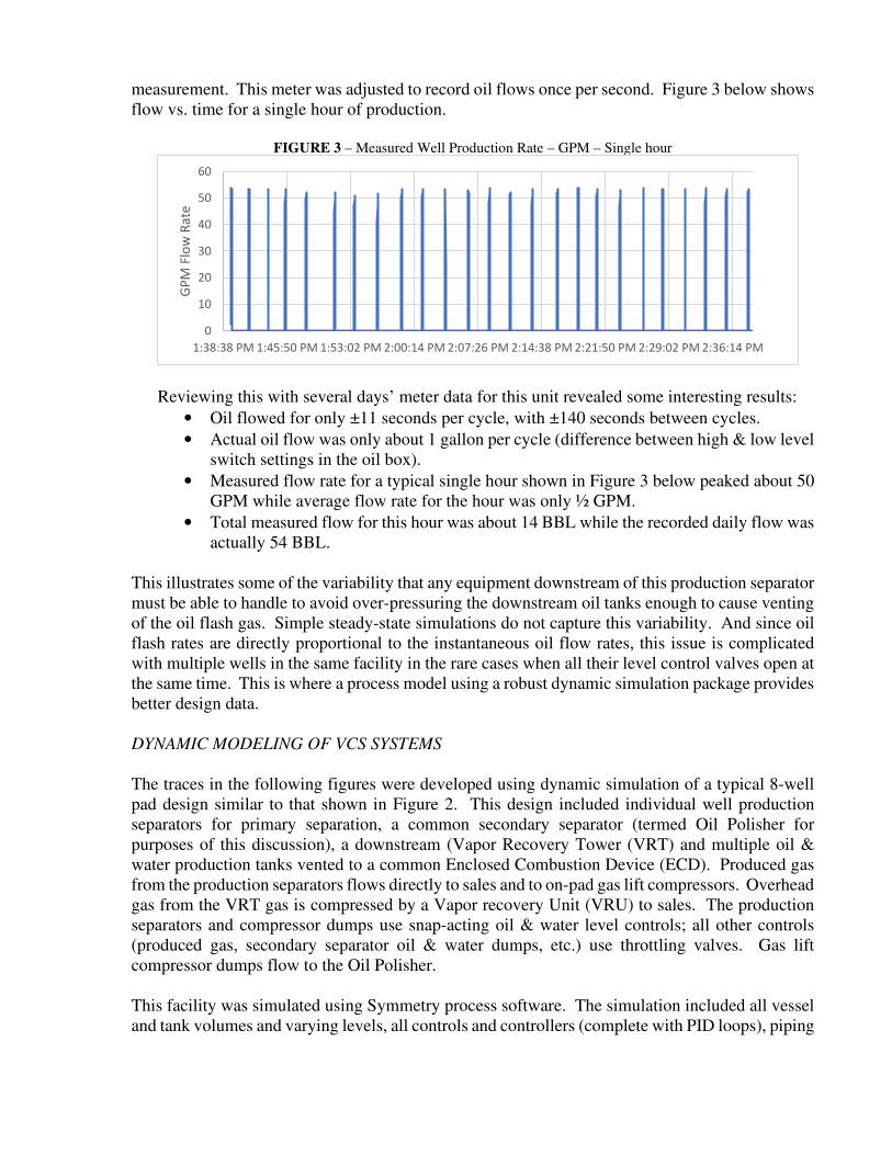
measurement. This meter was adjusted to record oil flows once per second. Figure 3 below shows flow vs. time for a single hour of production.
FIGURE 3 – Measured Well Production Rate – GPM – Single hour
Reviewing this with several days’ meter data for this unit revealed some interesting results:
• Oil flowed for only ±11 seconds per cycle, with ±140 seconds between cycles.
• Actual oil flow was only about 1 gallon per cycle (difference between high & low level switch settings in the oil box).
• Measured flow rate for a typical single hour shown in Figure 3 below peaked about 50 GPM while average flow rate for the hour was only ½ GPM.
• Total measured flow for this hour was about 14 BBL while the recorded daily flow was actually 54 BBL.
This illustrates some of the variability that any equipment downstream of this production separator must be able to handle to avoid over-pressuring the downstream oil tanks enough to cause venting of the oil flash gas. Simple steady-state simulations do not capture this variability. And since oil flash rates are directly proportional to the instantaneous oil flow rates, this issue is complicated with multiple wells in the same facility in the rare cases when all their level control valves open at the same time. This is where a process model using a robust dynamic simulation package provides better design data. DYNAMIC MODELING OF VCS SYSTEMS
The traces in the following figures were developed using dynamic simulation of a typical 8-well pad design similar to that shown in Figure 2. This design included individual well production separators for primary separation, a common secondary separator (termed Oil Polisher for purposes of this discussion), a downstream (Vapor Recovery Tower (VRT) and multiple oil & water production tanks vented to a common Enclosed Combustion Device (ECD). Produced gas from the production separators flows directly to sales and to on-pad gas lift compressors. Overhead gas from the VRT gas is compressed by a Vapor recovery Unit (VRU) to sales. The production separators and compressor dumps use snap-acting oil & water level controls; all other controls (produced gas, secondary separator oil & water dumps, etc.) use throttling valves. Gas lift compressor dumps flow to the Oil Polisher. This facility was simulated using Symmetry process software. The simulation included all vessel and tank volumes and varying levels, all controls and controllers (complete with PID loops), piping
0
10
20
30
40
50
60
1:38:38 PM 1:45:50 PM 1:53:02 PM 2:00:14 PM 2:07:26 PM 2:14:38 PM 2:21:50 PM 2:29:02 PM 2:36:14 PM
GP
M F
low
Ra
te

sizes, lengths and elevations, etc. In short, the model is high enough quality that it can be used to train operators The following traces were calculated for a situation where snap acting level control valves (LCV’s) on all eight production separators and all compressor dumps activate at the same time. The model included the detailed well production rate data shown above. Production rates for each well were adjusted to mimic typical operations and are set to vary ±10%. Figure 4 shows the calculated peak oil flow rates from the production separators and the Oil Polisher for a 1-hour period. Although the average oil production rate is 6.800 BPD, peak flows to the Oil Polisher are 30,000 BPD and peak flows to the VRT is 15,000 BPD. The difference is that the throttling valve on the Oil Polisher oil outlet LCV helps damp down the peaks from the production separators.
FIGURE 4 – Oil Flows - BPD
Figure 5 below shows the calculated gas flows from the Oil Polisher and VRT for a 1-hour period, along with total flows handled by the VRU and tank ECD. The peak calculated gas flow to the VRU is over 900 MSCFD, while peak calculated tank vent flow to the ECD is about 300 MSCFD. In contrast, the same calculated flow rates from a steady-state simulation of this facility are 615 and 182 MSCFD respectively.
FIGURE 5 –Gas Flows - MSCFD
0
10,000
20,000
30,000
40,000
0 500 1000 1500 2000 2500 3000 3500
SecondsTotal Oil fr Seps Total Oil fr Polisher
0.0
200.0
400.0
600.0
800.0
1,000.0
1,200.0
1,400.0
0 240 480 720 960 1200 1440 1680 1920 2160 2400 2640 2880 3120 3360 3600
Seconds
Gas Flows - MSCFD
Polisher Gas Flow VRT Gas Flow VRU Inlet Flow

Figure 6 below shows the calculated pressure in the oil & water tanks for a 1-hour period when the tanks are 80% full. In this case the Oil Polisher and VRT help damp down the gas flow and subsequent pressure spikes from the upstream equipment. The vapor volume in the tanks also “absorbs” some of this flow as the tanks’ pressure increases; effectively the empty volume in the tanks act like a gas surge system. Note that the peak pressure is over 6.5 oz/in2. The steady-state simulation predicts a lower pressure of about 4.6 oz/in2. While these pressures are well below the potential relieving level of 12 oz/in2 in the tanks (typically 75% of the 16 oz/in2 setting of common tank pressure relief valves) this is due to including an over-sized ECD in the design. However, if the facility design is based on a steady-state simulation with a calculated 10 oz/in2 tank pressure, that system could be at risk for tank venting and the forementioned regulatory actions.
FIGURE 6 – VCS Gas Flows (MSCFD) and Tank Pressure (oz/in2)
OIL POLISHER OPERATION
Most multi-well shale oil production pads use some sort of two-stage separation. The primary separators receiving the raw oil from the wells are either individual three-phase separators (heated or unheated) or a bulk/test separator. These separate the oil, water and gas into three separate streams. However, the bulk oil/water separation is rarely capable of removing enough water (also known as BS&W) to meet sales specifications. Therefore, most designs include a secondary separation that runs at lower pressure, most often a larger separation unit that treats multiple wells. For purposes of this paper we are calling this an Oil Polisher. Earlier facility designs such as represented by Figure 2 set the Oil Polisher operating pressure at 30-40 psig, with the polished oil flowing to either a VRT or straight to the oil storage tanks. This pressure is needed to be able to feed the Polisher oil to the top of the VRT. Oil entering the Oil
-50.0
0.0
50.0
100.0
150.0
200.0
0 240 480 720 960 1200 1440 1680 1920 2160 2400 2640 2880 3120 3360 3600
Seconds
Total Water Tank Gas Flash Oil Tank Gas Flash Total Tank Flash Gas to ECD

Polisher creates a flash gas due to the pressure drop, and oil sent to both the VRT and oil tanks also creates their own flash volumes. Gas from the polisher and VRT are normally combined and recovered by the VRU. Recent designs have been eliminating the VRT, running the Oil Polisher at the usual VRT ±5-10 psig pressure and using pumps to move the Polisher’s oil and water into the storage tanks. While this can increase the total amount of flash gas in the VRU it can also reduce the oil tank flash volume. Figure 7 shows the effects of these flow vs. Oil Polisher pressure. Note that the oil tank flash volume is reduced from±1,100 MSCFD to under 800 MSCFD. This can reduce the size of the oil tank VCS system, including reducing the size/number of ECD’s needed as well as reducing the total VOC’s that the plant produces for facilities that are not recovering this gas.
FIGURE 7– Flash Gas Flows (MSCFD) vs. Polisher Pressure (psig)
Eliminating the VRT reduces overall cost of the pad, both capital and operating costs. Capital costs of their installation are normally in the range of $100,000/VRT. And while a VRT theoretically has no direct operating cost, in practice they can need hot oiling to remove paraffin build-up. This is frequent in fields in colder climates and/or fields with paraffin issues in the oil. VRT’s have also been known to overflow, crude oil to the VRU suction lines which creates significant downtime and cleaning costs. These costs are offset by the pumps’ installation and operating costs, but the balance is in favor of the pumps over the VRT’s. These low pressure Polisher/pump systems are proving more reliable at lower costs than VRT’s.
0
20
40
60
80
100
120
0
200
400
600
800
1,000
1,200
5 10 15 20 25 30 35 40 45 50
Oil
Ta
nk
Fla
sh F
low
, M
SC
FD
Po
lish
er
& V
RT
Flo
ws,
MS
CF
D
Pressure, psig
Polisher Gas VRT Gas Total Flash to VRU Total Tank Gas

VENT GAS HANDLING – SYSTEM DESIGN
Most oil production facilities have been designed to collect the oil and water tank flash gases and burn them in either ECD’s or open flares. Many of these have been designed for very high destruction of the entrained VOC’s, but Environmental regulators typically only allow credit for 95% VOC destruction without testing and potentially 98% VOC destruction if the units are tested in place, often annual testing. As facilities get larger (with both an increase in the number of wells handled and improved production rates) and as the VOC limits get tighter, the VOC emissions from incomplete combustion of the tank flash gases become greater percentages of the allowable emissions. Eventually these emissions become the limiting factor in facility capacity; in one basin, these emissions can limit oil production rate to ±7,000-8,000 BPD. Newer and larger facilities are being designed to capture tank emissions by installing blowers to boost the gas to the suction of the VRU’s. One of the more common blowers is a packaged unit using rotary lobe (Roots-type) machines that can boost the gas from near atmospheric pressure to 5-10 psi. These units can come with robust control systems and are very reliable. In practice, the value of recovering this heavy gas offsets the installation and operating costs of the blowers. VENT GAS HANDLING – OXYGEN CONTAMINATION
One downside of such units is that it is possible to pull a vacuum in the tanks and/or piping and potentially get oxygen into the recovered gas. This can contaminate the recovered gas as well as the sales gas when the two are mixed. There have been three potential cures developed for this recently, each with its own advantages and drawbacks. Vacuum in the system isn’t the only potential for oxygen ingress. If water or oil is hauled into the facility from other facilities and the receiving facility is using vapor return lines, it is very probable that oxygen from the trucks’ tank will get into the VCS system and contaminate the recovered gas. This has also been seen in facilities that receive produced water via pipeline from other facilities. The first and lowest capital cost option to cure the oxygen problem is to install oxygen meters on the blower gas and vent it to an ECD or flare if the oxygen content becomes high enough to exceed sales gas specifications which are typically 10 ppmv oxygen. Since this gas is usually blended with larger volumes of produced gas, the oxygen limits for the recovered gas can be up to 100-500 ppmv. Installed cost of an oxygen meter is relatively low but the heavy molecular weight does require better gas sampling systems than regular pipeline gas requires to prevent liquid contamination of the oxygen sensor. The sample gas also needs to be taken from a point with a pressure of at least 5-20 psig (depending on the specific meter used) to permit flow through the meter.

A second option is to install catalytic oxygen conversion systems such as the Ecovapor system to convert the low oxygen levels to carbon dioxide and water vapor. These systems have been proven in several fields and have handled up to 5% oxygen in the total gas. They are normally installed downstream of the VRU compressors as the higher pressure keeps actual gas volumes lower and minimizes the size of the catalyst bed. These units operate at high temperatures (over 400°F) and do require significant electrical power at start-up to preheat the catalyst bed, although power requirements are lower after the unit hits its operating conditions. A third option is to install a Fuel Gas Conditioning Unit (FGCU) to remove the heavier components from the VRU discharge and use it for fuel gas. This concept does require a significant fuel load to consume the bulk of the treated gas, though typically large gas lift or sales gas compressor gas-fueled drivers can consume most or all the treated gas. Such a unit may need to be based on refrigeration rather than the more common J-T design due to the limited 150-250 psig pressures available from the VRU. These low pressures may not be high enough for a J-T design to achieve good fuel conditioning of this very heavy VRU gas. A system using refrigeration can also be designed to produce a liquid that can be sold as a heavy liquid at higher prices than standard NGL streams. VENT GAS HANDLING – HYDROGEN SULFIDE
Hydrogen sulfide content of shale oils and flash gases varies widely between field and between formations in the same field. Oil with 100 ppmw H2S content can produce total flash gas with an H2S content of 3,000 ppmv. This can require the removal of up to 1 LTD of sulfur in larger facilities and challenge the operation of any sulfur scavenger. The corresponding produced H2S content in such facilities is often high enough to require significant sulfur removal systems. A number of these have been installed using classic redox technologies. Some systems are available as rental units that can be removed for smaller units as the oil production declines. Sweet oil fields can also have enough H2S to cause downstream issues. VRU gases in these sites are often in the 100-200 ppmv H2S range and very suitable for sulfur scavengers, both injection type and fixed or fluid bed designs. Historically companies have been required to purchase the latter systems though rental units are also making inroads into the oil facilities. Again, that offers the advantage of replacing with smaller units as well production declines.
LOW PRESSURE SYSTEMS, MEASUREMENT AND CONTROL
The previous sections have focused on major facility equipment and processing practices to better control tank vapors. But one of the most important lessons learned from the study of tank vapor management has been the realization that low pressure systems should not be treated as traditional oil and gas processes. Low pressure systems require a more disciplined approach when it comes to measurement and automation.

Equipment pressures and piping/line pressures in traditional oil and gas processes are high enough (50 psig or higher) that velocity pressure of the process fluid is a minor factor when it comes to measurement and validation. Many gas process pipes are sized considering velocity limits (Mach 0.1 to 0.3) or erosional velocity limits. These criteria create designs such that the stagnation and static pressures are quite close to one another. Stagnation pressure, Pt, is basically the sum of the static pressure, P, and the velocity pressure of
the flowing fluid. A common example of this effect is a pitot tube, which measures the difference
between the stagnation pressure at its tip and the static pressure in the line to calculate the fluid’s
flow rate. Stagnation pressure is defined as:
�� = � �1 + � − 12 �� ��
Where Pt = Stagnation pressure, P = Static pressure.
M = Mach number, gas velocity relative to speed of sound in the gas.
γ = Gas specific heat ratio for the gas
Note: the term to the right of ‘P’ is equal to 1.055 for M= 0.3, γ = 1.2
While the differences between the static and stagnation pressures are small with gas flow in
traditional higher-pressure oil & gas process lines, the difference between static and stagnation
pressure can be significantly larger in low pressure lines. This can lead to incorrect placement of
pressure measurement devices, incorrect device selection, or inaccurate pressure measurement.
Ignoring the stagnation pressure effect when designing or operating low pressure gas lines can lead
to problems.
As an example of a higher-pressure applications, consider a gas capture line off a separator
operating at a static pressure of P = 62.2 psia, with M = 0.3, γ = 1.2. The resultant stagnation
pressure for that flowline would be 65.6 psia (62.2 x 1.055). An operator would probably use only
a static pressure transducer to monitor the system pressure because accuracy gained from using a
specialized pitot tube and pressure transducer provides no added benefit for measurement.
For a low-pressure example, consider a tank vapor control system (VCS) at an elevation of ~5000
ft (~1500 m) where barometric pressure is 12.2 psia (Colorado, DJ basin). For reference in this
scenario, 10 oz/in2 = 0.625 psi = 4.31 kPa; atmospheric tank system pressures are typically
referenced in oz/in2 and normally must be kept well below 16 oz/in2 = 1 psi in pressure. Vapors
from the tanks are routed through the vapor control system to a flare. The gas specific gas ratio is
γ = 1.2 and M =0.3 through the piping. The tanks have thief hatches that open at 10 oz/in2 (12.825
psia) in the tanks. The operator has installed a static pressure transducer directly at the inlet to the
flare.

The operator reads the static pressure transducer installed at the flare inlet and it reads 6 oz/in2 (or
12.575 psia). This could lead the operator to believe that the tanks are also at 6 oz/in2 and thus the
thief hatches on the tank are closed. However, the tank pressure (recognizing stagnation pressure)
is much higher, likely causing venting from the thief hatches [(12.2 +0.375) x 1.055 = 13.27 psia
= 17.1 oz/in2]. Upstream operators have realized this and begun installing pressure transducers on
the tanks themselves to control flare/combustor motor valves and start/stop signals to VRU’s.
Control valves affecting tank pressures need to be designed and tuned to provide stable tank pressures and prevent tank venting. For example, most facilities that use VRU’s to capture tank vapors also have a backup system to “letdown” tank vapors to a site flare or combustor if the VRU fails. This has typically been done with a large pneumatically actuated ball valve. This valve design may take 20-30 seconds to open which may not be quick enough to vent enough vapors to the flare to prevent a spike in tank pressure and potential tank venting. Large butterfly valves are another common option but these valves may operate too quickly. This can drop tank pressures fast enough to cause the valve to operate erratically. THIEF HATCHES AND RELIEF DEVICES: SANCTITY OF THE SEAL
Even with good line sizing and valve operation in the VCS system, thief hatches and PRVs on the tank systems are still susceptible to leaks around gaskets and soft goods. Upstream operators have come to appreciate the “sanctity of the seal”. Proper maintenance on regular intervals is key to preventing leaks, but it is also important to take design and operational steps to ensure that hatches and PRV’s (1) remain gas-wetted and (2) do not open during normal operations. Thief hatch and PRV soft goods are kept gas-wetted by minimizing exposure to air. This can be done by various designs, including: using mechanical gas blanketing or pulse purge blanketing systems (i.e., solenoid purge valves activated by decreasing tank pressures); by maintaining backpressure on the tanks with a motor valve or pneumatic control valve that opens to the flare/combustor; by using mechanical backpressure valves that use weighted plates; or with check valves that have a minimum opening pressure. The goal in each of these is to ensure tank pressure does not drop sufficiently low to activate the vacuum pallet on the thief hatch or the emergency vacuum valve. Both of these vacuum devices are extremely sensitive and can crack open way above their design cracking point (usually 0.4 oz/in2). Maintaining slight positive pressure in the tanks will significantly reduce exposure to air/oxygen, prolong the life of soft goods, and reduce the cost of leak detection and repair (LDAR) activities. Thief hatches also need to use proper soft goods for the environment. These hatches were commonly fitted with seals that are resistant to normal aliphatic hydrocarbon compounds. However, oil flash gases also have high concentrations of aromatic compounds as well and these will attack more conventional soft goods. Operators are switching to Viton or similar soft goods to minimize gasket failures and their subsequent leaks.

Tank level transmitters can also help prolong the life of soft goods. These support auto tank gauging systems that keep truck drivers from opening thief hatches for gauging. This minimizes oxygen entrainment, minimizes the risk of misaligned hatches (a common cause of leaking/venting) and the risk of leaving a hatch open. Other common causes of venting include clogged flame arrestors, liquids in the vapor line, and stuck open dump valves from upstream process equipment. All of these can be minimized with diligent maintenance programs, by installing flame arrestors vertically and by sloping vent lines to minimize liquid accumulation. Separator dump valves sticking open rank second behind vapor control system capacity issues in the most common cause of unintended tank venting. Some upstream operators have experimented with electronic separator dump valves or switched to instrument air actuation in lieu of instrument gas to eliminate control signal freezes that can keep a dump valve from closing. A recent design development to minimize this gas blow-by has been installing a shutoff valve downstream of the separation equipment and upstream of the tanks. The shutoff valve is triggered off high tank pressure to stop flow to the tanks. This prevents gas blowby and unintended lifting of relief devices that could lead to accelerated degradation of soft goods and subsequent potential regulatory issues. This “Closed Loop Vapor Control System” (controlling tank pressure by controlling the upstream facility) has been accepted by EPA and state regulators in recent Consent Decrees as a replacement for the Quad Oa Closed Vent System Design Analysis.
CONCLUSIONS Flash gas handling at shale oil production facilities has been evolving and growing more complex as these oil fields are developed. New completion and production techniques are resulting in greater flash gas handling requirements; new and more stringent air regulations are requiring a stronger focus on improved gas capture systems; and downstream pipeline specifications are requiring gas treatment of these captured flash gases. The increased volumes are trending across most production basins. The more stringent air regulations are currently affecting only a few basins but may well spread to other basins in the near future. And as regulators start focusing on similar emissions from gas processing and treating plants, the lessons learned from oil production and handling the resulting flash gas vapors will become increasingly valuable to these midstream facilities as well.


![Handing in Work through Moodle - static.packt-cdn.com€¦ · Handing in Work through Moodle [2 ] Handing in the work Work can be handed in through Moodle using the assignment activity.](https://static.fdocuments.net/doc/165x107/5f5b97f185bad95a9b198c03/handing-in-work-through-moodle-handing-in-work-through-moodle-2-handing-in.jpg)