
2021 EDITION THERMON
60
THERMON Thermon Product Applications EMEA PRODUCT APPLICATIONS a degree above | www.Thermon.com 2021 EDITION WORLD LEADER IN INDUSTRIAL PROCESS HEATING SOLUTIONS
Transcript of 2021 EDITION THERMON

THERMONThermon Product Applications
EMEA PRODUCT APPLICATIONS
a d
egre
e a
bov
e | w
ww
.Th
erm
on.c
om
2021 EDITION
WORLD LEADER IN INDUSTRIAL PROCESS HEATING SOLUTIONS

TABLE OF CONTENTS

THE
RM
ON
| a d
egree a
bove | w
ww
.therm
on.com
3
PROCESS INDUSTRIES SERVED
OIL & GAS PRODUCTION/STORAGE SOLUTIONSUnderground Gas Storage
Oil Field Redevelopment
LNG Production and Storage Facilities
Bitumen Storage Plant
Fuel Gas Skids/Compressors and Turbines
Hopper & Conveyor Solutions
Long Line Heating Systems
GENESIS NETWORK IN AN ETHANE CRACKER & POLYETHYLENE PRODUCTION FACILITY
OFFSHORE SOLUTIONSTank Terminals
Offshore Oil and Gas
MARINE SOLUTIONSArctic Offshore and Maritime
Shipping Applications Tankers IWW
Energy Saver for Steam Tracing Systems - SafeTraceTM
Engine Rooms and Service Lines
STEAM TRACING AND TUBING BUNDLE SOLUTIONSThermoTube® Pre-Insulated Tubing Bundles
Do Seal and Condensate Pots Need To Be Traced
WarmTraceTM Hot Water Temperature Maintenance
TubeTrace® Superior Construction
TubeTrace® vs. Field Installation
Carbon Monoxide Absorption/Migration in Analyzer Sample Lines
HeetSheet Tank & Vessel Heeting Unit Characteristics
RESIDENTIAL/ NON-HAZARDOUS SOLUTIONSRoof and Gutter Heating
Freeze Protection - Tunnels
POWER SOLUTIONS
MINING INDUSTRY
04
06
08
10
12
16
18
20
22
26
28
30
34
36
37
38
40
42
44
46
48
50
52
53
54
58
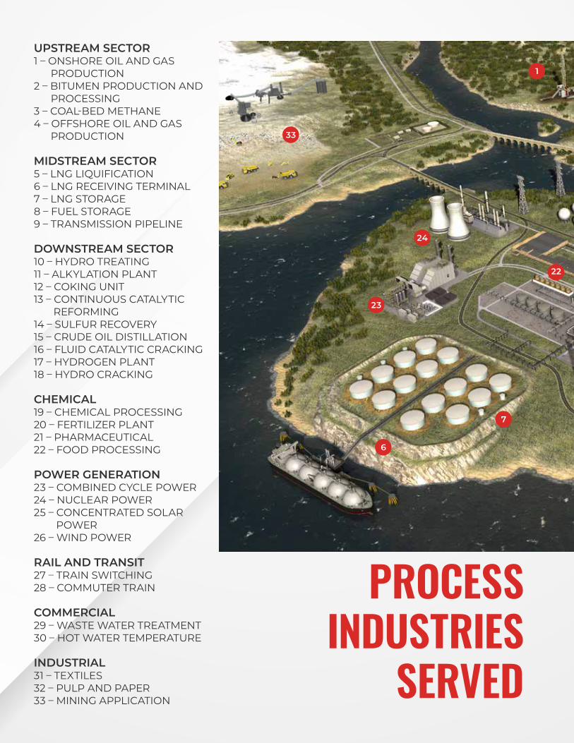
UPSTREAM SECTOR 1 – ONSHORE OIL AND GAS
PRODUCTION2 – BITUMEN PRODUCTION AND
PROCESSING3 – COAL-BED METHANE 4 – OFFSHORE OIL AND GAS
PRODUCTION
MIDSTREAM SECTOR 5 – LNG LIQUIFICATION6 – LNG RECEIVING TERMINAL7 – LNG STORAGE8 – FUEL STORAGE9 – TRANSMISSION PIPELINE
DOWNSTREAM SECTOR 10 – HYDRO TREATING11 – ALKYLATION PLANT 12 – COKING UNIT13 – CONTINUOUS CATALYTIC
REFORMING14 – SULFUR RECOVERY 15 – CRUDE OIL DISTILLATION 16 – FLUID CATALYTIC CRACKING17 – HYDROGEN PLANT 18 – HYDRO CRACKING
CHEMICAL19 – CHEMICAL PROCESSING 20 – FERTILIZER PLANT21 – PHARMACEUTICAL 22 – FOOD PROCESSING
POWER GENERATION23 – COMBINED CYCLE POWER24 – NUCLEAR POWER25 – CONCENTRATED SOLAR
POWER 26 – WIND POWER
RAIL AND TRANSIT27 – TRAIN SWITCHING28 – COMMUTER TRAIN
COMMERCIAL29 – WASTE WATER TREATMENT30 – HOT WATER TEMPERATURE
INDUSTRIAL31 – TEXTILES32 – PULP AND PAPER33 – MINING APPLICATION
PROCESS INDUSTRIES
SERVED
33
6
23
24
22
7
1
THE
RM
ON
| a d
egree a
bove | w
ww
.therm
on.com
5
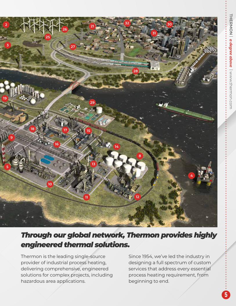
Thermon is the leading single-source provider of industrial process heating, delivering comprehensive, engineered solutions for complex projects, including hazardous area applications.
Since 1954, we’ve led the industry in designing a full spectrum of custom services that address every essential process heating requirement, from beginning to end.
Through our global network, Thermon provides highly engineered thermal solutions.
19
9
5
10
16
3
2
25
26
27
2132
31
30
28
4
8
1211
13
14
29
151718

APPLICATIONHeat tracing is used in numerous applications, each requiring specific knowledge and experience. One of the fields is heat tracing for freeze protection of gas lines and glycol lines in underground gas storage facilities. Typical examples are the Dutch UGS’s in Zuidwending (owner Gasunie), Norg/Langelo (owner Shell EP) and PGI Alkmaar (owner TAQA).
All heat tracing for these plants has been designed and supplied by Thermon. The main function of these UGS’s is providing a buffer supply of gas when under extreme conditions the normal supply of gas becomes insufficient.
UNDERGROUND GAS STORAGE (UGS)UGS NORGOne of the main sources of gas supply in Western Europe is the Dutch Groningen main gas field and a number of surrounding smaller fields. If at a certain ambient temperature the demand exceeds the supply from the Groningen field, the largest UGS will start producing. With decreasing temperature the demand will increase and the UGS will increase its production.
At some stage however transmission capacities are insufficient and force a regional storage facility (like PGI Alkmaar) into operation before the larger UGS has been used to its full extent. The send-out of gas from a UGS will not be completely limited to the actual moments it is really needed. In order to be prepared for send-out the UGS has to be in stand-by mode first. In this stand-by mode gas will be produced at a minimum flow level.
Source:nl.wikipedia Author: Thijs.nl Licensed under GFDL

THE
RM
ON
| a d
egree a
bove | w
ww
.therm
on.com
7
UGS ZUIDWENDING The end user is of this UGS is Zuidwending VOF in which Gasunie and Nuon are both participating for 50%. After Thermon successfully completed the UGS plant in Norg/Langelo, owned by Shell EP, it was a logical choice to involve our company again for the Zuidwending project. However this project is different as far as the underground part is concerned.
Underneath the Zuidwending site a huge salt dome is located; an underground salt mountain. For many years already Akzo Nobel has been extracting salt. This resulted in hollow spaces, called caverns. In the area there are 10 caverns of which 4 caverns, each having a capacity of 530.000 m2, will be used for the project. The top of the cavern is 1000 m below grade and the bottom 1350 m. So the whole Eiffel tower could fit in. The caverns are filled with gas from the nearby Slochteren field or from other foreign suppliers.
The main function of this UGS is providing a buffer supply of gas when under extreme conditions the demand exceeds the normal supply from the Groningen gas field, the UGS will start producing. The gas to and from the caverns is controlled by a plant consisting of 5 large compressors, main building, generator building, metering station and a process plant. It will be clear that the heat tracing plays a vital role. Heat tracing is among others required for freeze protection of gas lines and glycol lines.
The reliability of the gas supply at all times is eminent considering the economic consequences. It will be clear that the heat tracing plays a vital role. The Thermon self-regulating heating cables supplied for above project are BSX™ and HTSX™.
Zuidwending

OIL FIELD REDEVELOPMENTAPPLICATIONHeat Tracing is used in numerous applications, each requiring specific knowledge and experience. A typical application is heat tracing for oil fields and in this particular case the redevelopment of an oil field; the SRT Project. The end user of the project is NAM, nowadays called Shell EP, and the EPC was Jacobs Engineering. SRT is the redevelopment of the Schoonebeek oil field in The Netherlands.

THE
RM
ON
| a d
egree a
bove | w
ww
.therm
on.com
9
THE PASTIn 1943 a predecessor of the NAM, the Batavian Petroleum Company, discovered the Schoonebeek oil field. After the war the NAM started the exploration of this field which was the biggest onshore oil field in Europe, estimated to be 1 billion barrels. NAM was specially founded for this by Shell and Esso, each owning 50% of the company. Between 1947 and 1996 250 million barrels were extracted by means of sucker rod pumps, which could be seen everywhere in the north east of Holland. In 1996 the exploration stopped because of economical and technical reasons (the oil was very heavy) and all equipment was removed.
THE PRESENTAt present, 15 years later, new innovative technologies have been developed and the oil field became interesting again. As a result it was decided to redevelop the oil field again. This redevelopment consisted of steam injection, extraction and treatment of the oil. After that the oil is transported to a refinery in Lingen (Germany). The water that is left over is injected into empty gas fields that have been taken out of production.
To generate steam from ultra pure water a new water treatment plant has been built. The residual heat of a cogeneration plant is used to generate the steam. The good old sucker rod pumps did not return. The oil is extracted by means of state of the art high efficiency pumps. As a result over the next 25 years another 100–120 million barrels of oil can be extracted from this old oil field. This means an increase of 50% of the Dutch oil reserves.
Thermon designed and supplied the heat tracing for the following process installations:
• Central Treatment facilities (CTF)
• Combined Heat Power Plant (CHP)
• Well Sites (18 each)
• Water Disposal Facilities (12 each)
The complete design was made by means Thermon’s special VisiTrace 3D design software.
It is estimated that by 2020 gas will supply about 25% of the global energy demand and with the benefit of being a relatively clean fuel this percentage will further increase. As many of the world gas reserves are geographically isolated from the market LNG will play a major role in the efficient delivery of gas to the end user.
The production of LNG by conversion of natural gas to liquid is done in a series of processes that are commonly known as “gas trains”. During these processes the gas is cleaned and dried, liquefied by cooling to -160°C and stored in large LNG storage tanks ready for pumping to LNG Tankers.
LNG PRODUCTION & STORAGE FACILITIES
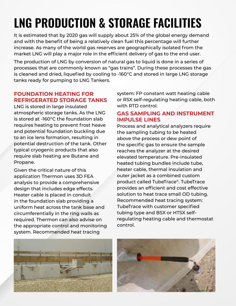
FOUNDATION HEATING FOR REFRIGERATED STORAGE TANKS LNG is stored in large insulated atmospheric storage tanks. As the LNG is stored at -160°C the foundation slab requires heating to prevent frost heave and potential foundation buckling due to an ice lens formation, resulting in potential destruction of the tank. Other typical cryogenic products that also require slab heating are Butane and Propane.
Given the critical nature of this application Thermon uses 3D FEA analysis to provide a comprehensive design that includes edge effects. Heater cable is placed in conduit in the foundation slab providing a uniform heat across the tank base and circumferentially in the ring walls as required. Thermon can also advise on the appropriate control and monitoring system. Recommended heat tracing
system: FP constant watt heating cable or RSX self-regulating heating cable, both with RTD control.
GAS SAMPLING AND INSTRUMENT IMPULSE LINES Process and analytical analyzers require the sampling tubing to be heated above the process or dew point of the specific gas to ensure the sample reaches the analyzer at the desired elevated temperature. Pre-insulated heated tubing bundles include tube, heater cable, thermal insulation and outer jacket as a combined custom product called TubeTrace®. TubeTrace provides an efficient and cost effective solution to heat trace small OD tubing. Recommended heat tracing system: TubeTrace with customer specified tubing type and BSX or HTSX self-regulating heating cable and thermostat control.

THE
RM
ON
| a d
egree a
bove | w
ww
.therm
on.com
11
LNG PROJECTS COMPLETED BY THERMON WORLDWIDE:
Note:This is only a partial list. Contact Thermon for a more comprehensive listing of completed and ongoing projects around the world.
EPC Owner Location Project
KJK Woodside Petroleum Australia Gas Trains 1–2,4
FW Woodside Petroleum Australia Gas Trains 5
JGC- KMSB-SIME MLNG Malaysia Gas Train 3
MHI Sempra Energy Mexico LNG Tanks
CBI- USA Shell Hazira Nigeria LNG Tanks
Chiyoda Snarmprogetti Ras Laffan Qatar Gas Train
Saipem SA Cartagena Spain LNG Tanks
Techimont ICB Shell India LNG Tanks
Daelim Skanska Korean Gas/POSCO Korea LNG Tanks
PROCESS TEMPERATURE MAINTENANCE Process and dew point maintenance for a variety of products transferred in pipelines within the plant. Typical products requiring electric heat tracing are oxazolidinone, waste vent gas, buffer gas and gas metering. Recommended heat tracing system: HTSX self-regulating heating cable or if higher maintain temperatures are required HPT power limiting heater cable or MIQ mineral insulated heater cable.
ELECTRIC HEAT TRACING STANDARDS AND CODES Thermon heat tracing systems are tested and certified by major approval agencies to international industry standards.

BACKGROUNDThe plant consists of three bitumen storage tanks and associated pipework including rail off loading, pumping and gantry tanker loading facilities. The pipework and tanks are to be maintained at between 120°C and 140°C.
The plant had been using a constant wattage cable since a site refurbishment project to change from steam to electrical tracing in the early to mid 90’s.
A PTFE sheathed cut to length constant wattage cable was installed on the pipework, utilizing multiple runs. A single core flexible constant wattage cable on the tanks was connected in three sections with three cables per section. Control consists of a main panel with electronic PT-100 controllers, controlling banks of circuits. The tanks are also controlled by PT-100 controllers located in the panel but have the facility to switch between star and delta for heat up capabilities.
CABLE REPLACEMENTSince initial commissioning, the plant had experienced a number of tracer failures resulting in the need to remove the insulation to facilitate either a repair or replacement of a section of cable. The cables on the pipework were failing on valves and flanges where close contact to the body of the valve or flange was not guaranteed. This was causing over heating of the cable and the soldered joints to fail.
The cables on the tanks had also failed with the requirement of major insulation removal to replace them. One of the tanks has had the trace heating replaced.
THERMON’S SOLUTIONIn 2002 Thermon was asked to provide a long term solution to overcome the problems experienced on site. A review of the site was undertaken with the client representative responsible for the site. This review looked at the current faults and the areas most prone to failure, i.e. pumps.
Depending on the line size the original design used either two or three heating cables. It was concluded that lines with two tracers had a higher risk of blockage should a tracer fail. There was one particular line that caused continual problems and this was singled out as an ideal section to trial with Thermon product.
The line was to be replaced with Thermon’s HPT Power Limiting Heating Cable.
BITUMEN STORAGE PLANT

THE
RM
ON
| a d
egree a
bove | w
ww
.therm
on.com
13
HPT-OJ HEATING CABLES HPT power limiting heating cables are designed for use with a wide range of trace heating systems from frost protection to high temperature process applications up to 200°C. The cable is ideal for applications where steam cleaning or purging precludes the use of lower temperature heating cables or where very high temperature maintenance is required. The withstand temperatures of up to 260°C de-energized is not restricted by either frequency or duration of exposure.
The power limiting feature of the cable is initiated by the coiled metal alloy resistance heating element which has a positive temperature coefficient. The metal alloy heating element is helically wrapped around a fibre substrate to create a unique composite heating element. The thermal expansion relief created by the fibre, coupled with the impact resistance it provides, makes HPT-OJ a highly durable heating cable.
The cable has a PFA Teflon jacket, followed by a nickel plated copper outer braid, providing a high degree of mechanical protection and corrosion resistance and a PFA Teflon overjacket.
HPT-OJ cables are able to provide significantly higher outputs than conventional cables when used at higher temperatures, which results in the use of less cable and hence reduction in cost. Another feature of the cable is its low start-up current characteristic which ultimately reduces power distribution requirements.
HPT-OJ cables are certified to the ATEX directive for use in Zone 1 and 2 classified areas and have a Temperature Classification of T2 to T6 (dependent on output).

UNDERTAKING THE TRIAL SECTION A Thermon installation engineer was employed to install the trial section with the site electrical engineer in attendance to receive training to enable the client to undertake future installation work.
Upon successful completion of the trial section an opportunity then arose to replace the trace heating on the pump section. One of the cables had failed and the remaining tracers were not maintaining the temperature.
This is one of the most demanding areas for heat tracing on site. The pumps are exposed to the elements and form an important part of the plant, performing both rail off loading and tanker loading.
The pump section was stripped and replaced with HPT. Both installations were deemed a total success.
THE WAY FORWARDThe client continued the replacement of the constant wattage cables with Thermon’s HPT cable and having installed between 500 m – 1000 m of cable without subsequent failure, and has experienced the major benefits of using Thermon products.
The client has also employed Thermon to replace the heat tracing on two of the three storage tanks. These were undertaken during shutdown periods and utilized Thermon’s mineral insulated (MI) cables and Thermon site personnel. The installation consisted of over 1100 m of MI cable per tank and the design utilized the existing control system and junction boxes so as to reduce the overall cost of the project. The stripping and replacement of the thermal insulation was also with the Thermon scope, thus providing a full turnkey package.
BITUMEN STRORAGE PLANT CONTINUED

THE
RM
ON
| a d
egree a
bove | w
ww
.therm
on.com
15

BACKGROUNDGas Compressor Stations are required on long distance gas pipelines to boost pressure and ensure adequate flow.
The compression facilities may consist of Low Pressure (LP) Reciprocating compressors, LP Turbine compressors or High Pressure (HP) Turbine compressors.
The fuel gas can be supplied to each compression unit directly from the Fuel Gas distribution header. The normal source for satellite fuel gas is raw gas from the discharge of the LP compressor which is processed through a Fuel Gas Scrubber to remove condensed water and hydrocarbons. A back-up supply can be sourced from a HP gas discharge header.
The Turbines which drive compression units can show evidence of damage to the fuel gas nozzles, combustors and turbine blades, as a result of high temperatures in the combustion chambers. This damage significantly shortens the service life of these components and increases the risk of catastrophic failure of the turbine blades.
Investigations by equipment manufacturers have concluded that the erosion and degradation is due to heavy ends (C6+) in the fuel gas entering into the combustor in the liquid phase and causing high temperatures, flame impingement of the turbine blades.
Pressure changes in fuel gas line systems, can also cause the ‘refrigerant effect’ due to down stream pipe sizing changes/restrictions during flow conditions, resulting in upset system conditions with inline instrumentation and flow monitoring. If this decrease in temperature results in the gas falling below the dew point temperature, gas hydration will form. Even in tropical climates , the formation of hydrates is possible. Formation of hydrates in the gas creates problems for the compressors, for example friction wears out blades and damages the compressor itself. In severe cases such as in low ambient temperatures, ice can form within the gas lines blocking flow to cities and other critical operations.
When the Gas Compressor is in standby mode (no flow) heat loss will occur resulting in lowering of gas temperature to ambient. If ambient is below product dew point it will result in unwanted condensation in the following equipment:
• Main Gas Lines• Well Heads• Gas Compressor Stations• Knock Out Pots• Instrumentation• Feed Lines from Gas Pre-Heater to Turbine
FUEL GAS SKIDS/COMPRESSORSAND TURBINES

THE
RM
ON
| a d
egree a
bove | w
ww
.therm
on.com
17
SOLUTIONS1. Concern of Turbine Damage: The recommendations are that the inlet
temperature of the existing fuel gas to the turbines, during flow and operation, should be raised above the dew point of the existing fuel gas to avoid any resulting damage to the turbines or instrumentation performance issues due to low temperatures. This can be a maintain or heat up temperature application and the solution is to determine the anticipated heat loss under all conditions utilizing the Thermon Computrace design tool and select the best available Thermon heat tracing cable packaged system for the project.
2. ‘Refrigerant Effect’ & Formation of Hydrates: This is generally a Heat up application and therefore the combined values of the maximum flow rate (kg/second) under the worst case conditions, heat capacity of the gas (kj/kg/°C) and the required temperature increase will need to be known (as a minimum) by the Thermon design engineers, for calculation and assessment to determine and select the most suitable Thermon system for the project and end user.
Purpose designed and purpose made Thermon MIQ high output heaters are excellent watts/metre value, and are very reliable for the long term and a superior heater cable solution for high power input applications.
There is also the range of Thermon BSX, RSX, KSX, HTSX, VSX Self-regulating heater cables and the HPT Power limiting cables that the Thermon design engineers can select and use where suitable.
All Thermon designed and selected heat tracing systems have the appropriate worldwide approvals and certification for electrically hazardous areas.

APPLICATION Reliable and effective hopper heating systems play an important role In the removal of fly-ash from precipitators and baghouse hoppers.
The hopper must be designed for preheating the hopper to prevent moisture condensation from collecting in the hopper during startup conditions in addition to maintaining the hopper (and fly-ash) above the fluegas acid dew point during normal operating conditions.
PRODUCT Instead of using resistance wires the Thermon HT hopper heater module contains an unconventional high temperature Inconel 600 heating element, providing multiple paths, eliminating series wire burnout which is typical for the conventional heating systems. The HT hopper heater has proven to be the ultimate solution in numerous installations. The heaters do not need to be replaced anymore during a plant stop.
They even survive the hoppers! It is almost common practice that when the hoppers are replaced the heaters are mounted again on the new hoppers.
HOPPER & CONVEYOR SOLUTIONS
PRODUCT FEATURES • Parallel Circuit Heating Elements
• Reliable Connection Design
• Low Watt Density
• Vibration and Shock Resistance
• Rugged Construction
• Ease of Installation
A hopper heater life time of more than 20 years is quite normal!

THE
RM
ON
| a d
egree a
bove | w
ww
.therm
on.com
19
FIELD EXPERIENCE During the last decades many designs andoperating procedures have been tried to minimize or eliminate hopper pluggage caused by compaction, agglomeration and solidification. Many of the earlier designs were based on solving the compaction problem only by means of poke tubes and mechanical vibrators. Hopper heating was recognized as by far the most practical method to prevent agglomeration and solidification.
Earlier designs mostly using MI cable (or sometimes heating panels with resistance wires) proved to be very unreliable. Failure was mostly caused by mechanical damage, vibration and chloride stress corrosion.
It was even considered quite an achievement if the heaters survived until the next boiler maintenance was carried out, during which the MI cable was mostly replaced.
Sometimes MI cables failed after such a short time that operators gave up and went back to hammering and using pokes. Thermon, manufacturer of amongst others MI cable, recognized that this specific problem demanded a specific solution. As a result the HT hopper heater module was designed 30 years ago already and it has been the landmark for reliability ever since.

APPLICATIONPipelines which transfer product over long distances often require heat tracing to facilitate material flow and prevent freeze-ups. Electric heat tracing is usually the most economical method. Thermon has the products and the application knowledge to offer the best solution.
HEAT TRACING SELECTIONProper selection of the heating method and materials can easily be shown with the following example. The reduction of the number of power points is the decisive factor.Length of pipe ............................................................. 1000 metersInsulation polyurethane ....................................................50 mmMaintenance temperature ....................................................60°CMinimum ambient temperature ......................................-20°C
Heat Tracing Layout Options Cable Length (m) Number of Power Points
Thermon SX Self-Limiting Heat Trace 3200 11
Thermon TESH Series Heat Trace 6150 4
Thermon ThermTrac System 1000 1
LONG LINE HEATING SYSTEMS

THE
RM
ON
| a d
egree a
bove | w
ww
.therm
on.com
21
OPERATING CHARACTERISTICSThe heating element of the ThermTrac™ system incorporates a ferromagnetic heating tube and a copper, insulated, heat resistant conductor. These two components are connected to each other at one end of the circuit with the conductor installed inside the heat tube, and connected to an alternating current (AC) power source at the other end.
When the system is energized, current flows through the heat resistant conductor to the connection point, then is concentrated into the inner surface of the heat tube by the skin effect phenomenon and the attendant proximity effect.
This electromagnetic interaction insures that the return current flow travels on the inner surface of the heat tube with virtually no measurable voltage on the outer surface.
With a ThermTrac™ system a pipeline length up to 20,000 m can be traced with a single power point!

THE GENESIS NETWORKModern industrial facilities are highly complex ecosystems which require frequent maintenance to minimize down time and maximize profitability. Traditionally, heat tracing required a significant amount of time and money for initial installation and routine maintenance/troubleshooting alarms. The advent of Industrial Internet of Things (IIoT) technologies have made life easier in nearly every industry and the introduction of wireless connected devices for heat trace installation, control and monitoring will lead to cost and time savings for facilities.
Thermon has developed the Genesis Network, the premier wireless connected system for monitoring and controlling heat trace. Genesis Network provides a total solution for operational awareness and site-wide visibility. Users save on maintenance hours, increase up-time, and can make upgrades and changes with greater flexibility. Additionally, users can easily monitor, maintain, and troubleshoot even the largest heat trace systems that may include over 10,000 heat trace circuits.
CASE STUDYPetrochemical facilities, like all types of processing sites, strive to minimize costs during installation and recurring maintenance. The Genesis Network will help customers save in both situations. To understand the potential cost savings, we compared wired vs. wireless quotes for a medium size downstream petrochemical facility. This site utilizes five refining units, 169 control panels, and 8,770 heat trace circuits that cover the 386-acre location.
When quoting the wired installation, most of the costs are related to the installation of the wiring/cable tray and associated man hours. The actual design of the heat trace system takes additional time as engineering has to determine the most efficient way to run the miles of cable throughout the facility.
Wired Wireless % Saved
Engineering, Design $30,000 $15,000 50%
Installation Materials $90,000 $5,000 94%
Installation Cost $100,000 $5,000 95%
Instruments & Gateways $30,000 $100,000 (233%)
Total $250,000 $125,000 50%
THERMON’S GENESIS NETWORK IN AN ETHANE CRACKER & POLYETHYLENE PRODUCTION FACILITY

THE
RM
ON
| a d
egree a
bove | w
ww
.therm
on.com
23
The wireless system saves in the design, installation, and wiring costs. The Genesis Network is comprised of the Genesis Bridge, which acts as a wireless transmitter/mesh node/repeater for other bridges, the Genesis Gateway which is the interface between the control room and mesh network, and the Genesis Server which is the software used to control the network. An additional benefit of the mesh network is it is self-healing, which enables the network to continuously find the optimal route if nodes fail.
Cost savings are not only realized during the initial installation of the Genesis Network, but facilities can also save a significant amount of money on an annual basis through optimizing more efficient maintenance and fault checking with the Genesis Server. In this example, for routine maintenance over the course of a year, a site should be able to save ~$35,000 or 86% of maintenance man hours.
Routine Maintenance/Health CheckWithout Digital
CommunicationsWith Digital
Communications
Total Man Hours 2 0.25
Maintenance Cost $110 $15
Yearly Cost $40,040 $5,460
Savings $35,000 or 86%

The Genesis Network is the first true IIoT system to provide users with the ability to monitor and control their heat trace from the control room. The Genesis Server provides site-wide alarm status and history, trace heater performance, panel setting management, IIoT device network management, quick access to drawings, and custom operational reports. It provides the secure and robust connectivity of a wireless mesh network that self-heals and adapts to ensure connectivity between controller and control room.
Alarm/Fault Event*Without Digital
CommunicationsWith Digital
Communications
Total Man Hours 3.5 1.5
Maintenance Cost $200 $80
Yearly Cost $72,000 $29,120
Savings $40,000 or 60%*Costs based on one fault per week
Maintenance teams are usually notified by the Automation/Control room teams about an alarm/fault. There is great value in reducing the time for the diagnostic period along with accuracy. Remotely diagnosing the problem will save hours in time on roundtrip travel to a panel, along with being able to grab the correct tools, materials, and supplies before heading out for a service call. When evaluating cost savings on an alarm/fault, this facility could save up to $40,000 per year for a total savings of almost $70,000/year using the Genesis Server.

THE
RM
ON
| a d
egree a
bove | w
ww
.therm
on.com
25
KEY FINDINGS
INSTALLATION COST SAVINGS
MAINTENANCE COST SAVINGS
• Wireless systems require less complex engineering/design plans
• Lower installation costs offset the higher product costs with the wireless solution
• Installation of a wireless system could save the facility as much as $125,000 or 50% over a wired solution
• Improved communication between Maintenance teams and Automation/Control room teams about events
• Reduction in diagnostic period and improved accuracy
• Remote diagnosis saves time on travel, ability to grab the correct tools, materials, and supplies
• Yearly cost saving could be ~$70,000/year
Total Savings to the Facility:$125,000 in Installation Costs
$70,000 on Yearly Maintenance Costs~$200,000 Year One Savings
CONCLUSIONThermon’s Genesis Network is a total solution providing full operational awareness of the heat trace system. Implementing this solution will create additional ROI, lower installed cost, and more flexibility over a traditional wired network. Customers using the Genesis Network will save time and be more efficient in maintenance operations.
Genesis Network is the future of IIOT heat trace technology and delivers industry leading benefits including browser interface, automatic software updates, and BI integration. This platform will continue to grow, enhance and offer additional value over time.

APPLICATIONHeat tracing is used in numerous applications, each requiring specific knowledge and experience. One of the fields is heat tracing for tanks, pipelines and jetties in tank terminals. The use of a heating tracing system is essential to warrant the quality and the properties of the various products that are unloaded, stored and loaded. A typical example of this is the new Rubis tank terminal in the Botlek area near Rotterdam in The Netherlands.
TANK TERMINALSRUBIS TERMINAL is part of the French Rubis group which is active in LPG distribution and the public storage sector. The terminal in Rotterdam will use existing jetties that have been improved. The new liquid bulk terminal has amongst others 4 stainless steel tanks of 2.500 m3 each and 6 mild steel tanks of 12.500 m3. The 77.000 m2 site has an on-site rail connection directly linked to the Betuwe Route, the dedicated freight line with Germany and the European hinterland. At the dock side the maximum depth is 12.65 meters.
Thermon was granted the order for design, supply, installation and insulation of the complete heat tracing system for pipelines, tanks and jetties by Royal Haskoning, the EPC contractor of the project. Thermon finished the project under extreme time pressure to full satisfaction of the customer.

THE
RM
ON
| a d
egree a
bove | w
ww
.therm
on.com
27
APPLICATIONHeat Tracing is used in numerous applications, each requiring specific knowledge and experience. One of the fields is heat tracing for loading arms.
Loading arms are typically used for loading all kind of chemical and petrochemical products into seagoing tankers, barges, trucks and rail cars.
For many products the use of heating cables is essential to warrant uninterrupted flow of product even at low temperatures. However, this application is generally underestimated as far as the complexity of the design is concerned. In general the product transport part of loading equipment is characterized by piping sections and swivel joints. Some parts are insulated some are not.
These uninsulated areas represent very substantial heat sinks and hence
LOADING EQUIPMENT
potential problem areas. Standard calculation methods are insufficient to provide the proper heat tracing solution.
Only extensive experience can protect you against serious problems. Thermon has acquired this experience through numerous installations.
TYPICAL APPLICATIONS ARE:• Marine loading arms
• Top and bottom loading arms for truck and rail transportation
• Pharmaceutical and food industry

APPLICATIONOffshore Platform’s, FPSO’s, FSO’s, ships and drilling rigs commonly require the application of electric heat tracing systems for the following reasons.
FREEZE PROTECTION25% of known oil and gas resources are located in extremely cold areas and therefore ships and platforms destined for these regions and other cold locations will require varying levels of freeze protection. Freeze protection of piping, valves, fittings and instrument tubing for fire protection water, potable water, sea and fresh cooling water, drill water and bilge water discharge. Anti-icing (kept ice free) e.g. door seals, ballast tank vents and cargo system valves. De-icing (ice removal in 4–6 hours) e.g. helidecks, gangways, walkways, ladders, antenna, scuppers, railings and freezer room doors.
Recommended heat tracing system: BSX or RSX self-regulating heating cable with ambient sensing thermostat control.
Process Temperature Maintenance Oil and Gas products can also require electric heat tracing for process temperature maintenance of pipes, instrumentation and tanks in the following typical situations: High wax content and/or pour point of crude oil Vapour pipeline’s from product tanks. Hydrate prevention on gas pipelines. Anti condensation heating on gas pipelines. Recommended heat tracing system: KSX or HTSX self-regulating heating cable with self-regulating control. Personnel Comfort Heating cables installed in the floors of changing rooms. Recommended heat tracing system: BSX or RSX self-regulating heating cable with floor sensing thermostat control. Electric Heat Tracing Standards and Codes – Thermon heat tracing systems are tested and certified by major approval agencies to international industry and shipping standards.
Offshore Oil and Gas Projects Completed by Thermon Worldwide:
EPC Owner Location Project
Samsung Sakhalin Energy Korea Sakhalin 2 LUN-A Oil Drilling Platform
SHI Sovcomflot Korea H1660 Artic Shuttle Tanker
Mitsubishi (MHI) Nippon Yusen Japan De icing of heliport LNG tanker
Keppel Hitachi Zosen Singapore Wooly Butt FPSO
Shanghai Waigaoqiao Bohai Oil Singapore BZ-25 FSO
Clough OMV Malaysia Maari Well Head Oil Platform
OFFSHORE OIL AND GAS

THE
RM
ON
| a d
egree a
bove | w
ww
.therm
on.com
29
Note: This is only a partial list. Contact Thermon for a more comprehensive listing of completed and ongoing projects around the world.

EXPLORATIONIn the 21st century a major increase in demand is changing the global energy market. In order to meet the demand, the international oil and gas industry is exploring the globe in search of new energy resources. Oil and gas exploration companies are being challenged to provide highly technical and environmentally sensitive solutions.
The Arctic region contains a large part of world’s undiscovered oil and gas resources. However, exploration and production in the Arctic, where companies and humans are faced with extreme temperatures down to -60°C, is a difficult undertaking.
HARSH ENVIRONMENTSIn the high north Arctic and polar regions the extremely low ambient temperatures and high winds create snow and ice conditions that require unique operational considerations.
Thermon provides solutions for winterization, temperature maintenance anti-icing and de-icing systems on Arctic
ARCTIC OFFSHORE & MARITIMEvessels and structures. These systems help provide a safe working environment to ensure the safety of personnel and the operation. With over 60 years in the trace heating industry,
Thermon is a proven leader in providing heating solutions for offshore and maritime applications.
Thermon SolutionsIn polar and Arctic environments ice formation on exposed surfaces creates serious problems impacting the safety of personnel and operations. The ice formation can be caused by sea spray and/or snow, rain and fog with the low ambient temperature. Thermon has developed anti-icing and de-icing solutions for offshore support and supply vessels, icebreakers, semi-submersible drill ships and platforms.
The trace heating systems are designed to ensure that all pipes, vessels, instruments and equipment are adequately protected for operations in low temperatures with cold sea water and high wind.

THE
RM
ON
| a d
egree a
bove | w
ww
.therm
on.com
31
Thermon trace heating solutions are specifically designed to provide a safe work environment for platforms, escape ways and helidecks. With over 60 years experience in the heat tracing industry, Thermon will evaluate each design and provide a complete heating system.
Typical needs for trace heating on FPSO’s and FSO’s are deck lines for oil, chemical products. Thermon has designed trace heating systems for freeze protection and temperature maintenance of:
• Loading and unloading lines
• Gas/vapor return lines
• Strip and cleaning lines
• Fuel oil lines
• Storage tanks and vessels
• Deck and tank cleaning lines
• Fire protection lines
• Engine room fuel and drip lines
• Cross-over lines
• Manifolds
• Safety showers
FOUR DESIGN PHILOSOPHIES APPLY:• Anti-icing: ice and freeze prevention where surfaces will be maintained above
freezing under the ‘worst case’ ambient design conditions.
• De-icing: removal of accreted ice in a reasonable and defined period of time.
• Winterization: anti-freeze for piping, valves, instruments and equipment containing fluids.
• Process temperature maintenance: temperature maintenance of piping, valves, instruments and equipment.

ENGINEERING & PROJECT MANAGEMENTThermon provides experienced engineering and project management services. Thermon Engineering evaluates heat loss predictions from heat transfer models to establish thermal loads via Finite Element Analysis (FEA) and Computational Fluid Dynamics (CFD) to confirm temperature distribution. Thermon provides an optimized thermal design with a suitable electrical load balance.
ARCTIC OFFSHORE & MARITIME CONTINUED

THE
RM
ON
| a d
egree a
bove | w
ww
.therm
on.com
33

ApplicationHeat tracing is used in numerous applications for the shipping industry, each requiring specific knowledge and experience. One of the typical fields is heat tracing for deck lines on motor tank ships for oil, chemical products, bitumen and edible oil.With substantial success Thermon has designed heat tracing systems for freeze protection and temperature maintenance of:
• Loading and unloading lines• Gas/vapor return lines• Strip and cleaning lines• Fuel oil lines• Storage tanks and vessels• Deck and tank cleaning lines• Fire protection lines• Engine room fuel and drip lines• Cross-over lines• Manifolds• Safety showers
All Thermon heat tracing cables used for the shipping industry are in compliance with the requirements of Lloyd’s RegisterMaintenance up to 65°C ..................................BSX Heat TraceMaintenance up to 121°C ..............................HTSX Heat TraceMaintenance up to 149°C ........................ VSX-HT Heat TraceAll above mentioned materials comply with standards IEEE515, CSA 130.03, and IEC 62086-1 and EN 60079-7The installed heat tracing materials can either be controlled by local thermostats or by means of the Thermon electronic heat tracing controller TC816, often located in the wheel house or engine room. More and more the electronic controller is used for controlling and monitoring the pipeline temperatures from one central point for safety reasons and not at least single man operation.
SHIPPING APPLICATIONS TANKERS-IWW

THE
RM
ON
| a d
egree a
bove | w
ww
.therm
on.com
35
ENGINE ROOMS AND SERVICE LINESAPPLICATIONThe shipping industry also utilizes heat tracing in engine rooms and service lines.
One of the projects Thermon engineered and supplied was the heat tracing for the Audacia. This ship was originally built as a bulk carrier but converted into one of the world’s biggest pipe laying vessels. The Audacia can weld and lay pipes up to 60” to a depth of 3500 m at a rate of
ELECTRIC TRACING WAS USED FOR THE FOLLOWING APPLICATIONS:
• Working air system• Fire main system• Fire fighting lines• Sprinkler lines• Pulper lines• Waste water lines
Last but not least Thermon supplied the special products SafeTrace and ThermoTube. SafeTrace is a pre-insulated steam tracer with reduced heat output, allowing for longer lengths and less steam traps. ThermoTube is a pre-insulated steam supply and return line.SafeTrace and ThermoTube were used for steam heating the following applications:
• Fuel oil service system• Fuel oil drain system• Fuel oil vent and overflow system
In total, about 3500 m electric heat tracing, 850 m ThermoTube and 2800 m SafeTrace were installed.
up to 7 km per day. The concept of the ship was entirely developed by Allseas, the Dutch company operator of the ship. The length of the ship (excluding the stinger of 106 m)is 225 m and can accommodate a crew of 240. The ship is equipped with three engine rooms, one for normal propulsion, the other two for powering the six electric thrusters, allowing for exact dynamic positioning.

APPLICATIONFor over six decades Thermon has helped heat tracing customers to get more heat out of their steam tubing. Very well known products in that respect are the Thermon Heat Transfer Compounds as well as the ThermoTube® pre-insulated tubing.
To meet the demands of the today’s steam market and to replace the traditional “one type fits all” concept of the past used in applying bare convection tracers Thermon designed a variety of new convection steam-tracing options, the SafeTrace™ product range. The design engineer may now choose convection tracers from several levels of heat delivery such as Standard Heat, Light Heat and Extra Light Heat. Each of these new types of external convection steam tracers offer a different level of heat delivery potential. These tracers with reduced heat delivery provide more practical temperature maintenance levels in the temperature range of 10 to 100 °C which covers a majority of the heat tracing applications and consequently can contribute to a considerable steam saving.
Steam tracers run both beneath the insulation as well as extend out of the insulation at flanges, valves equipment and expansion joint areas. These areas can be potential burn areas for the plant personnel who maintain the facility. The SafeTrace™ products have a unique “touch-safe” characteristic. This has been achieved by applying one or more non-thermally conductive coverings to steam tube’s exterior surface which reduces the instantaneous heat flow from the surface into the skin during an accidental touch event.
SafeTrace™ BENEFITS• SafeTrace IT tracers comply with ASTM Std C-1055 for
skin exposure temperatures of less than 60°C.
• Permits winterization for any size of pipe.
• Predictable temperature control.
• Eliminates hot/cold spots associated with bare metal tracers and spacer blocks.
• Prevents damage to temperature sensitive or corrosive products.
• Reduced installed costs.
• Lower operating/maintenance cost because of reduced steam usage up to 50%.
• Fewer fittings resulting in less maintenance and repair.
• No galvanic corrosion between pipe and steam tracer.
ENERGY SAVER FOR STEAM TRACING SYSTEMS - SAFETRACETM

THE
RM
ON
| a d
egree a
bove | w
ww
.therm
on.com
37
GENERALTubeTrace® is quite often considered as a very nice but expensive solution. In case accurate cost comparisons are made it becomes very obvious that TubeTrace® is more economic than any conventional application. Not only compared with normal insulation but also with the lower price/quality snap-on types of insulation.
COMPARISONThe basis for the comparisons shown alongside is:
• Tube diameter: 12 mm
• Material: SS 316
• Number of tubes: 1
• Freeze protection type of self-regulating heating cable
CONCLUSIONThe comparisons do not only show that for the example given at a bundle length of 7 meter TubeTrace® is more economical (depending on the type of TubeTrace® required this can even be as short as 3 meters) but also that a considerable saving in installation time can be achieved.
Conventional insulated applications and applications with snap-on type of insulation take respectively 4 and 3 times longer than TubeTrace®!
TubeTrace® ADVANTAGES• Less engineering disciplines involved.
• No coordination with insulation contractor.
• Reduced scaffolding hiring time
• Extruded outer jacket – no ingress of moisture so no deterioration of insulation or corrosion of tubing
ENGINE ROOMS AND SERVICE LINES

GENERALFactory manufactured Pre-Insulated Tubing Bundles – ThermoTube Bundles provide a quality, cost effective and long term solution to the need for insulated steam & fluid supply/condensate return requirements.
Traditional means have included the use of pipe in stick form welded at length in the field by mechanical contractors, field insulated with either rope wrap or pipe section insulation and clad with mastic or metal by the insulation contractor.
The disadvantages of this traditional method can include a high total install cost, having the need for multiple contractors on site which extends the install time and significant ongoing maintenance. The quality of this system also relies on the skill of the contractors – once insulation becomes wet or missing – the effectiveness of the system is compromised with increased heat losses.
THERMOTUBE® PRE-INSULATED TUBING BUNDLES
ADVANTAGES INCLUDE:• Can be supplied in coil lengths up to 150
meters and cut to length on site.
• The bundle comes complete with tube, non-hygroscopic fiberglass insulation and a flexible polymer outer jacket.
• Once on site, simply attach and complete connection to tube fittings and seal the exposed ends of the bundle.
• The finished product is aesthetically pleasing and is of a uniform high quality that requires no further maintenance.
• Designed to be ‘touch-safe’ reducing risk of burns for operations personnel.
ThermoTube® is available in all tube materials and sizes. 316 SS welded/seamless and copper in 3/8”, 10 mm, ½” and 12 mm are commonly used and regularly stocked.

THE
RM
ON
| a d
egree a
bove | w
ww
.therm
on.com
39

Customers will sometimes ask if seal and condensate pots should be heat traced. The answer depends on how these devices are used. There are two terms we need to deal with as they relate to instrumentation: “condensate pots” and “seal pots”. Both devices are similar in appearance but have slightly different functions. These terms have other meanings as they relate to steam handling systems.
Condensing Chamber “Seal Pot”
Steam Drum
Slope
HP
LPLT
(Reverse)
DO SEAL & CONDENSATE POTSNEED TO BE TRACED?
CONDENSATE POTSCondensate pots are used to catch and hold condensate and foreign material. This helps keep manifold orifices clean and free of foreign material. They are located upstream of the instrument and have a bottom drain so that they may be cleaned. We do not often see condensate pots used in this manner for instrumentation. If a condensate pot is used in this manner it will usually require heat tracing.

THE
RM
ON
| a d
egree a
bove | w
ww
.therm
on.com
41
SEAL POTSSeal pots (sometime called condensate pots) are used to allow a liquid seal between the instrument and flowing gases such as steam. Their function is to keep the liquid level constant in the impulse tubes.For example, in boiler liquid level applications the high pressure (HP) side of a differential pressure transmitter is connected to the vapor space on top of the steam drum. Steam condenses in the chamber or seal pot and fills the impulse line with condensate. The seal pot is located to allow the condensate to drain back to the source thus keeping the liquid level constant.Insulating the seal pot would inhibit its function. The seal pot, unlike the impulse tubes, is not generally vulnerable to freezing during normal plant operation because it is in constant contact with a
heat source, steam. The only time that the seal pot is vulnerable to freezing is if the plant is shut down during freezing ambient temperatures. In this case the seal pot would need to be drained.
ROOT VALVESWhile addressing the subject, another question often asked is, “Does the root valve need to be heat traced?” The root valve is a safety device. It is used to shut off the system in case of a downstream leak. In this application the root valve is normally open. As previously discussed, the seal pot is located to drain back through the root valve to the source. If installed and operated correctly there is no situation where the root valve would be filled with water. The water would always drain back into the pipe or vessel and therefore should not require heat tracing.

APPLICATIONA hot water Heat Tracing system provides an alternative to the design and installation of hot water systems for prompt delivery of hot water at the fixtures.
Self-regulating cables eliminate some of the problems associated with conventional commercial hot water systems – providing the end user with instant hot water without the need for re-circulation pipework, balancing valves and pumps.
More importantly, a Thermon WarmTrace system provides the end user with a hot water system that has a low carbon footprint due to its significant energy savings. No more overheating at the source and no more water wastage due to waiting for hot water at branch outlets.
WARMTRACE TM HOT WATER TEMPERATURE MAINTENANCE SYSTEMS
THE SYSTEMElectric heat tracing systems replace heat lost through thermal insulation on hot water supply piping to maintain the water at desired nominal temperatures (e.g. 50°C, 60°C), preventing stagnant water in dead leg lines from cooling. It also ensures that hot water is readily available when required at fixtures.
Self-regulating cables are taped to the supply piping and insulated. The cable can be cut to length, tee spliced, and terminated on site without the need for special tools.
The self-regulating phenomenon occurs along the entire length of the heat traced supply line, to balance the heat output of the cable with the heat loss of the insulated pipe, therefore outputting heat only where it is required, without the need for additional thermostat control.

THE
RM
ON
| a d
egree a
bove | w
ww
.therm
on.com
43
FOR THE ENGINEER:• Reduces layout time compared to
re-circulation systems
• Easily adapted to buildings with multiple temperature zones
• Greater flexibility for buildings with complex designs
• Excellent for retrofit or building additions
• Helps meet greater environmental requirements – for more ‘green’ building designs
FOR THE PLUMBING CONTRACTOR:
• Faster and less expensive to install when compared with a re-circulation system
• Metallic and non-metallic pipes can be heat traced
• Simple to use pipe mounted connections which require no special tools
• No maintenance call backs
• Can complete a project in stages
FOR THE OWNER:
• Saves water by maintaining hot water at the fixtures
• Lower operating cost
• No moving parts means no maintenance
• Realizes important and significant energy savings
For an advanced, cost effective approach to water saving and water heating, consider a THERMON WarmTrace hot water temperature maintenance system.

As the saying goes, don’t judge a book by its cover. This holds true for pre-insulated and traced tubing bundles. From the components to the manufacturing process, not all tubing bundles are the same. A properly engineered and manufactured pre-insulated and traced tubing bundle consists of quality approved components, providing a reliable and cost effective solution.
Thermon’s flexible manufacturing process allows the combination of heat tracers (electrical and/or fluid) with all tubing types available in the market today. Consistency and quality are a prerequisite in all Thermon manufacturing processes. Understanding the components used, and how Thermon TubeTrace tubing bundles are manufactured, provides a self-assuring, cost effective product solution.
TUBETRACE® SUPERIOR CONSTRUCTION

THE
RM
ON
| a d
egree a
bove | w
ww
.therm
on.com
45
Thermon’s “cabling” process is used on many product combinations, including non-metallic tubing. Cabling ensures an even contact for proper heat transfer and provides a stress relief for all components within the bundle. Once the tubing and tracer are cabled together, the thermal insulation is helically wrapped. This method prevents the bundled tubing and tracer from relying solely on the insulation and outer jacket to bond the components together. The internal components and thermal insulation are then protected with a continuous extruded polymer jacket, including UV protection.
Thermon’s cabling process provides a pre-engineered, predictable, repeatable and performance pleasing product solution. Whatever the application – freeze protection, high temperature (maintenance and/or exposure) or sensitive analyzer lines – Globally, Thermon manufactures and provides a complete line of superior heat tracing product solutions.
CONSTRUCTION - “CABLING” OF TUBING & TRACER• Allows ease of bending in any plane or direction
• Provides stress relief for components within tubing bundle
• Increases reliability and longevity of the product
• Components remain uniform when bending expansion loops

The following is a comparison between the installations of TubeTrace preinsulated tubing and field routed, heat traced, and insulated tubing for a differential pressure transmitter application. There are other benefits besides the obvious up front cost savings. Other benefits include increased reliability, lower purchasing costs, and lower inventory costs. The reliability issue is easy to see once you understand how tubing is installed, insulated and heat traced in the field.
The field insulated and heat traced system consists of straight sticks of tubing joined with compression fittings. Typically, the tubing is routed from a primary element such as an orifice plate to a pressure transmitter along existing structure and secured in place with conduit or tubing clamps at 5’ intervals. It is important that both tubes are routed parallel and together otherwise each tube would have to be heat traced and insulated separately causing the installation cost to increase significantly.
Heater cable is applied to the tubing and secured in place with tape at 1’ intervals. Special attention must be paid to clamping areas where the tubing is secured to existing structure. These metal-to-metal contact points are major heat sinks requiring extra heat or thermal insulation. Heater cable may need to be applied serpentine in these areas to provide extra heat. This is no easy task considering the relative size of the heater cable compared to the tubes.
Thermal insulation is applied by spiral wrapping the tubing and heater cable with 2” wide by ¼” thick woven fiberglass insulation. The insulation is wrapped at a 50% overlap for a total thickness of ½”. There may be great difficulty wrapping the tubing near clamps, especially if the clamps are not adequately spaced away from structure. Again, these are critical heat sink areas where the tubing is most likely to freeze.
Once insulated, mastic is painted over the entire installation. This mastic provides sealing from water. However, the mastic will crack and loose integrity after about 6 months. New sealing coats should be applied periodically.
Inventory and purchasing costs are also higher for the field insulated system. The field insulated system requires 7 components compared to 3 TubeTrace
TUBETRACE® VS. FIELD INSTALLATION
Typical Field Installations

THE
RM
ON
| a d
egree a
bove | w
ww
.therm
on.com
47
DESIGN CONDITIONS:Instrument Tubing Required: (2) 1/2” x .049” 316 SS Seamless TubesTube Length 30’ from orifice tap to DP transmitterMaintenance Temperature ............ 50°FAmbient Temperature -20°F, 25 mph windAvailable Power .............................. 120 Vac
Case A: Field Traced and Insulated Instrument TubingMaterial Labor
½" 316 SS Seamless Tubing (20' sticks) 60' @ $2.50/ft $ 150.00 7.2 hrsBSX Self-Regulating Heater 35' @ $4.85/ft 169.75 2.40 hrsHeater Cable End Terminations 93.25 1.25 hrsTape for Heater Cable and Insulation 9.25 --½" 316 SS Unions (2) @ $10.50 21.00 .25 hrsThermal Insulation, woven 2" x .25" thick 94' @ .60/ft 56.40 7.50 hrsLayers Waterproofing Mastic (2) @ $4.00 8.00 --
Total Labor @ $25.00/hr -- 18.60 hrsSub-Totals $ 507.65 $ 465.00
Total Installed Cost $ 972.65
Case B: TubeTrace® Pre-Insulated Heat Traced TubingMaterial Labor
TubeTrace #ME-4F2-42-3-ATPVC-049 32' @ $17.05/ft $ 545.60 3.90 hrsTubing Bundle End Seals FAK-7 12.25 .50 hrsHeater Cable End Terminations 93.25 1.25 hrs
Total Labor @ $25.00/hr -- 5.65 hrsSub-Totals $ 651.10 $ 141.25
Total Installed Cost $ 792.35
components. The TubeTrace system only requires contact and coordination with one vendor. The field insulated system requires contacting at least 4 vendors.
It is easy to see why TubeTrace preinsulated tubing bundles are cost effective solutions to instrument heat tracing applications. Not only are up front costs lower, reliability is significantly increased for both the short and long term. Clamping areas have little effect on the thermal efficiency of TubeTrace. The thermal insulation is machine wrapped consistently to controlled thickness tolerances. You can expect even and consistent temperatures throughout the installation improving instrument accuracy. TubeTrace is manufactured from continuous coils of tubing reducing potential leaks by eliminating in-line fittings. And finally, the outer jacket of TubeTrace is continuous extruded plastic impervious to water and weather for the life of the installation.

Increased electrical power generation with gas fired combustion turbines brought new challenges for Continuous Emissions Monitoring Systems (CEMS). This was particularly true where combined cycle co-generation units with Heat Recovery Steam Generating (HRSG) systems and steam turbines were installed.
One of the gases measured in flue gas analyzer systems is carbon monoxide (CO). Carbon monoxide gas is very common in the air we breathe but can sometimes be a measurement challenge in sensitive gas analyzers used in CEMS applications.
A difficult issue that was identified several years ago related to abnormally high carbon monoxide levels in flue gas streams. Could the generating units truly be “out of compliance” or could there be an extraneous source of carbon monoxide contaminating the gas samples?
CARBON MONOXIDE ABSORPTION/MIGRATION IN ANALYZER SAMPLE LINES
Flue-gas monitoring often takes place at different locations in a power generating unit’s exhaust gas streams. What was unusual in a few installations was whether the sample point was at the combustion turbine (the HRSG by-pass) or at the exhaust stack for the cogen power train, after the HRSG. Efforts to “zero-out” background levels of CO became even more challenging, as levels were inconsistent and brought risks of potential fines for suspected off-spec performance.
Pre-insulated Fluoropolymer Tubing with Power-Limiting Electrical Heat Tracing
“HEATED UMBILICALS” OR “HEATED TRANSPORT BUNDLES” SUCH AS TUBETRACE® HEATED INSTRUMENT TUBING ARE COMMONLY USED TO ENSURE A
GAS SAMPLE REMAINS ABOVE ITS DEW POINT.
THE
RM
ON
| a d
egree a
bove | w
ww
.therm
on.com
49
Notes1. Data complements of Extrusions Plus, Spring, Texas.2. Sometimes referred to as “burn in” this refers to the procedure of heating the
sample line for an extended period of time prior to commissioning to deplete the contamination source. However, the length of time required to achieve satisfactory results has been difficult to predict.
3. SilcoSteel is a high performance coating as applied by Restek of Bellefonte, PA, USA.
DIFFERENT LENGTHS OF HEATED INSTRUMENT TUBING SEEMED TO YIELD DIFFERENT CARBON MONOXIDE LEVELS.
Flue gas samples are collected by the probe and transported under a slight vacuum to the gas detector and analyzer system. In many applications fluoropolymer tubing is specified because it is lightweight and more flexible than metal tubes, plus it is inert to most gases. In cases where flue gases contain sulphur, chlorine, and/or nitrogen as combustion by-products, any acids that condense may attack metal tubes.
Fluoropolymer tubing can absorb trace amounts of carbon monoxide into its surface from other materials used in fabrication of pre-insulated tubing bundles. These trace amounts can then appear as background emissions and affect the accuracy of the CO detection system. Sources of carbon monoxide include the fiberglass insulation material, as well as Mylar tapes used in bundle fabrication. Compensation for this “background noise” can generally be accommodated during the calibration of the analytical instrumentation system.
Fluoropolymer resins and tubing absorb low molecular weight gases in trace amounts. Because of this characteristic, some grades of fluoropolymers are often used for manufacturing semi-permeable membranes. As a tubing material, various gas molecules can pass through or migrate through the fluoropolymer tubing wall from the outside.
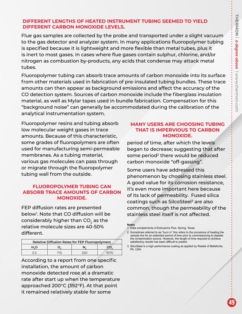
FEP diffusion rates are presented below1. Note that CO diffusion will be considerably higher than CO2 as the relative molecule sizes are 40-50% different.
According to a report from one specific installation, the amount of carbon monoxide detected rose at a dramatic rate after start up when the temperature approached 200°C (392°F). At that point it remained relatively stable for some
period of time, after which the levels began to decrease; suggesting that after some period2 there would be reduced carbon monoxide “off-gassing”.
Some users have addressed this phenomenon by choosing stainless steel. A good value for its corrosion resistance, it’s even more important here because of its lack of permeability. Fused silica coatings such as SilcoSteel3 are also common, though the permeability of the stainless steel itself is not affected.
FLUOROPOLYMER TUBING CAN ABSORB TRACE AMOUNTS OF CARBON
MONOXIDE.
Relative Diffusion Rates for FEP FluoropolymersH2O O2 N2 CO2
0.2 715 320 1670
MANY USERS ARE CHOOSING TUBING THAT IS IMPERVIOUS TO CARBON
MONOXIDE.

HOW ARE HEETSHEET UNITS CONSTRUCTED?HeetSheet units are plate-type heating units made of two sheets of 20 or 26 gauge 304 stainless steel conforming to ASTM-A240. The sheets are seam-welded to define the fluid holding portion. Interrupted seam welds are arranged to provide a variety of parallel passageways for steam or other heat transfer fluids to pass through the HeetSheet unit.
HeetSheet units’ internal volumes are below the ASME limits 5 ft3 at 250# (0.14m3 at 1720 kPa) that would require certification. So, HeetSheet units can withstand relatively high pressures and temperatures, but still be lightweight and pliable.
HOW DO HEETSHEET UNITS WORK?HeetSheet units may be installed on flat or curved surfaces. Each unit is designed for a specific tank and includes tubing inlet and outlet connections. The 26 gauge units also include a special non-hardening heat transfer compound applied to the surface that will contact the tank wall. This eliminates all air pockets and creates an uninterrupted path for the heat through the tank wall, and into the product being heated within the vessel.
WHAT IS THE EFFICIENCY OF HEETSHEET UNITS?Heat is transferred to the tank wall at a rate of 114 to 227 W/m2-K (20 to 40 Btu/hr-°F-ft2) For comparison, typical externally installed plate-type tank heating coils deliver heat at a rate of approximately 17 to 28 w/m2-K. For this reason, 2 to 3 times more surface area can be required for conventional external plate-type-heating coils to maintain the same temperatures with HeetSheet units.
HOW CAN HEETSHEET UNITS BE SAFER?HeetSheet units are applied to the external wall of a tank; therefore, no danger of cross contamination between the process fluid and the steam exists. Cross contamination is a concern with internal steam heating coils and jacketed tanks and vessels.
HEETSHEET® TANK & VESSEL HEATING UNIT CHARACTERISTICS

THE
RM
ON
| a d
egree a
bove | w
ww
.therm
on.com
51
WHY ARE HEETSHEET UNITS MORE ECONOMICAL?The fast and simple installation of HeetSheet units makes them more economical. Each 26 gauge unit weighs only about 9.8 kg/m2 (2 lb/ft2) compared to almost 40 kg/m2 (8 lb/ft2) for a typical external plate-type-heating coil. Heavy coils often require lifting equipment for handling, with difficult mounting techniques resulting in higher labor cost.
By comparison, two workers can easily install a HeetSheet unit of the largest 20 gauge size. Then, simplified banding methods and lesser coverage combines to permit the installation of HeetSheet units in minutes compared to hours for other methods.
WHERE ARE HEETSHEET UNITS TYPICALLY INSTALLED?HeetSheet units can be an economical heating or cooling method on most process plant tanks and vessels. They may be used in a wide variety of applications where other types of internal or external plate heating coils are typically used. Common applications include temperature maintenance for: caustic soda, phthalic anhydride, soap, paraffin, syrup, sulfur, asphalt and “heavy ends” materials, naphthalene, malaic anhydride and many food products.
WHAT ARE THE RATINGS FOR HEETSHEET UNITS?HeetSheet units are rated for use with 10.34 bar g (150 psig) steam pressure at temperatures of 186°C (366°F) when used with NH (Non-hardening) heat transfer compound. Higher pressures with correspondingly higher temperatures may be designed if the NH material is not employed. Product temperatures to 177°C (350°F) can be maintained in tanks, vats, or other types of vessels.
WHAT ARE THE SIZES FOR HEETSHEET UNITS?HeetSheet units are available in standard external dimensions of 0.61 m (2 ft) in width and lengths of 0.61 m (2 ft); 1.22 m (4 ft); and 2.44 m (8 ft). Special lengths of 0.91 m (3 ft) and 1.83 m (6 ft) are available upon request, as are special widths of 0.3 m (1 ft).
Heat Transfer Compound
Heat Transfer Medium
Inlet/Outlet
InsulationHeating Panel
Tank Wall

The heating cable selected was the special heavy duty Thermon series cable type TESH. To meet the designed power output the heating cables were connected to a power supply 400 V, 3 phase. The complete system is switched on and controlled by a snow detector, installed at a height of 5 cm. The system will melt the snow within one hour so that critical snow levels can never be reached. In order to limit the start up current the heat tracing system has been split up in three heating zones switching on with a time delay.
During the first year of operation a test was done with a snow height of 20 cm to check the melting response of the system. For a snow height of 20 cm it took six hours to completely melt the snow and drain it safely. Depending on weather conditions, it takes less than an hour to melt 2 cm of snow.
Snow accumulation on flat roofs can cause dangerous situations if no measures are taken. When snow builds up and the weight increases ultimately the roof can collapse and human life can be at risk. Over the past two years that’s already happened in a number of cases with schools, shopping centers, and sport accommodations. On request of the owner of a big shopping center Thermon designed and supplied a heating system to protect a roof of 1,500 m².
ROOF AND GUTTER HEATING
Because of the roof size and to keep the total cost of ownership as low as possible it was decided to:
• Design a heating system only for critical snow melting and escape routes.
• Select a heating cable minimizing the number of electrical circuits.
Of the 1,500 m² roof surface 1,000 m² is equipped with electric heating cables, at a spacing of 15 cm, resulting in a total length of 6,000 meters of heating cable, divided over 450 heating circuits.
THE
RM
ON
| a d
egree a
bove | w
ww
.therm
on.com
53
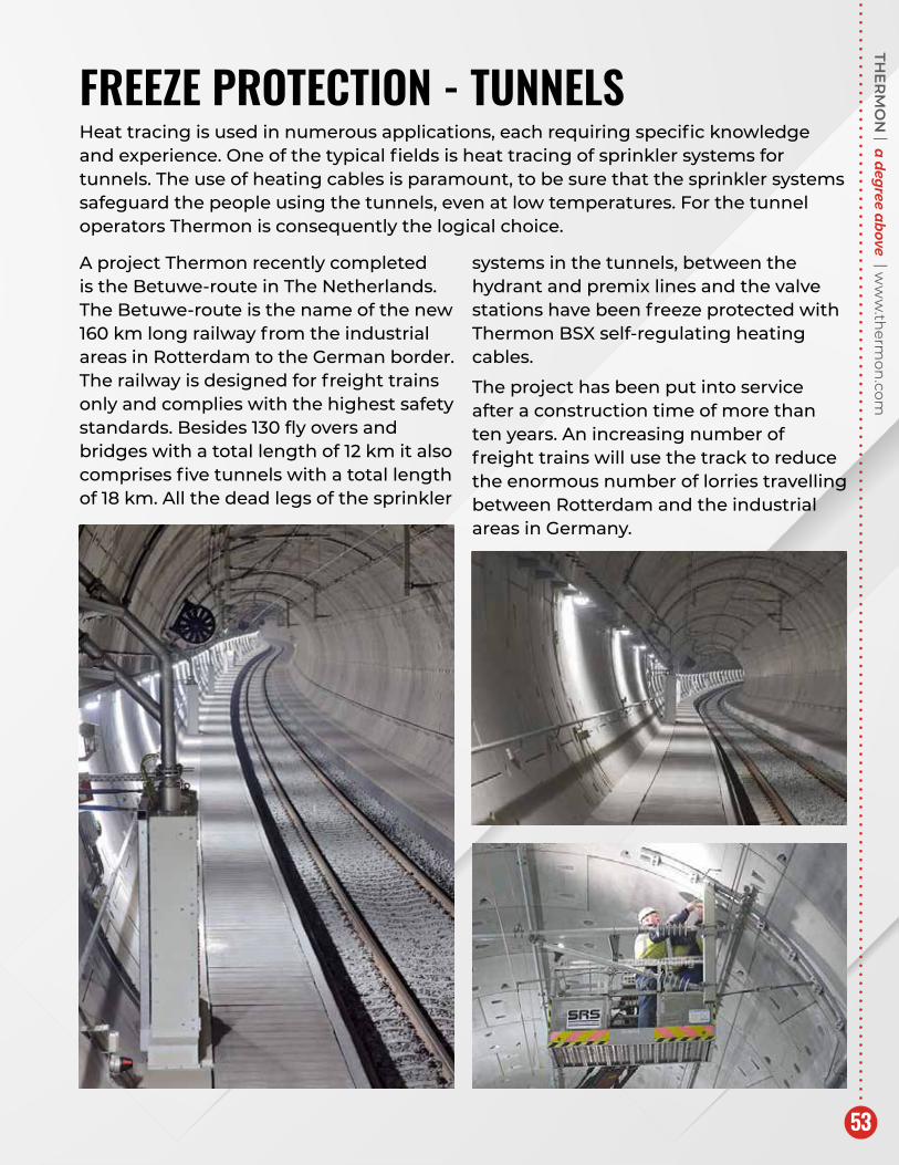
Heat tracing is used in numerous applications, each requiring specific knowledge and experience. One of the typical fields is heat tracing of sprinkler systems for tunnels. The use of heating cables is paramount, to be sure that the sprinkler systems safeguard the people using the tunnels, even at low temperatures. For the tunnel operators Thermon is consequently the logical choice.
FREEZE PROTECTION - TUNNELS
A project Thermon recently completed is the Betuwe-route in The Netherlands. The Betuwe-route is the name of the new 160 km long railway from the industrial areas in Rotterdam to the German border. The railway is designed for freight trains only and complies with the highest safety standards. Besides 130 fly overs and bridges with a total length of 12 km it also comprises five tunnels with a total length of 18 km. All the dead legs of the sprinkler
systems in the tunnels, between the hydrant and premix lines and the valve stations have been freeze protected with Thermon BSX self-regulating heating cables.
The project has been put into service after a construction time of more than ten years. An increasing number of freight trains will use the track to reduce the enormous number of lorries travelling between Rotterdam and the industrial areas in Germany.

Our global population continues to grow, yet the livable space cannot be changed. This ever evolving growth brings with it demands that are real and challenging. The need for electricity is one of those demands. To meet that requirement, the need for Grassroot Combined Cycle electrical power generating projects continue to rise for many reasons:
• Ever-Increasing Global Power Demands
• Decommissioning of Older Plants
• Premature Retirement of Globally Positioned Nuclear Power Generating Stations
Generating power is not new, but the way its produced continues to be very controversial. Natural gas has long been embraced and agreed upon as a clean burning fuel with limited emissions. Additionally, its cost continues to fluctuate at levels making it attractive to increase production through “fracking”. This method continues to make it attractive and cost prohibitive to develop more Gas –fired Combined Cycle Co-Generation plants on a global scale.
POWER GENERATION
TubeTrace Bundles are ideal for CEMS
Typical HRSG units capture Combustion Turbine exhaust to generate steam. This is most often used for additional power generation.

THE
RM
ON
| a d
egree a
bove | w
ww
.therm
on.com
55
When power generation is required to satisfy “base load” electrical power needs, the hot exhaust gases are directed to a HRSG (heat recovery steam generator) where the thermal energy is captured to generate steam. Some industries, like refineries and chemical plants, use this steam for process operations, but primarily it is used to generate electrical power via a steam turbine. The steam in a boiler and its feed water is generally treated with 50% caustic for de-mineralization.
HRSG cross-section reveals steam sampling and chemical injection lines that require EHT and/or insulation to reduce heat loss and/or for personnel protection.
The main steam transport and chemical feed lines often require electrical heat tracing to maintain temperatures, preventing crystallization. In addition, safety showers and eye wash stations may require electrical heat tracing to insure a constant flow of properly maintained water for safety purposes. In lower ambient climates and where sub-freezing is possible, winterization (freeze protection) of critical lines may be necessary, such as:
• Water Lines
• Fire Protection Lines
• Instrument Lines
• Sample Lines
• Drains

To ensure the HRSG is operating properly, the steam is carefully analyzed and chemically adjusted on a continuous basis. To prevent condensation from freezing and damage to the turbine, winterization of the small diameter chemical feed and steam sample lines (LPS, IPS & HPS) is typically solved by using a properly engineered pre-insulated and heat traced tubing bundle. In most cases the steam sample lines are routed to a common analyzer shelter, which may be more than 100M (328 ft.) or more apart.
Thermon TubeTrace type SEI/MEI-HT/HTX is a pre-engineered solution and designed for this purpose with exposure temperatures up to 593ºC (1100ºF), maintaining freeze protection, yet protecting the heat tracer from the elevated steam exposures, providing a worry-free flow and performance year-
POWER GENERATIONafter-year. In some cases, where ambients are not subject to freezing, heat tracing may not be required. However, the tubing must be insulated and designed to withstand the elevated exposures – for the process and personnel protection. Thermon ThermoTube type SL-HT/HTX is the perfect solution for this requirement.
In addition to protecting the chemical feed, steam sample and instrument lines, the environmental governing agencies typically require monitoring of methane, volatile organic compounds and other trace gases that are associated with the production, processing, storage and transport of natural gas at the stack. Emissions in the exhaust gases passing through the SCR (Selective Catalytic Reduction) at the HRSG are also monitored for CO and NOx. Thermon TubeTrace type SE/ME products are designed to provide accurate samples and run time.

THE
RM
ON
| a d
egree a
bove | w
ww
.therm
on.com
57
Products and uses for consideration are:
• Thermon Electric Heat Tracing – For Piping, Tanks, Vessels, Etc.
• Thermon Pre-Insulated and/or Heat Traced Tubing – For High/Medium/Low Pressure Steam Lines, Instrument Lines, Chemical Feed Lines, SCR and Stack Gas Analytical Sample Lines, Etc.
• Thermon Hopper Heaters
• Thermon Heat Trace Control Systems
In addition to the electrical heat tracing and pre-insulated and/or heat traced tubing bundles, Thermon also offers and provides the complete line of termination kits, accessories and controls as well as a full plant audit services and turnkey installations.

Applications: Heat Tracing applications in the mining industry can be generally classified into two distinct areas.
• Mining & Extraction: There are limited process requirements and the need for heat tracing solutions results from, where applicable, freezing ambient temperatures. Thermon can provide winterization utilizing electric heat tracing of slurries, product handling chutes & conveyors and potable/non potable water in pipes, tanks and instrumentation.
• Mineral Processing: There are a variety of potential heat tracing applications including ammonium nitrate (in manufacturing & storage), grease (storage & pipe work for servicing of trucks & equipment), 49% sodium hydroxide (PH control in water treatment), acids (leaching of gold),black liquor (alumina processing), environmental precipitator/fly ash control, continuous emissions monitoring of stack gas, magnesium & shale oil processing, fuel gas pipe work prior to turbines and heavy fuel oil.
Solutions: Thermon has over 50 years of heat tracing design and application experience and has a full range of electric, steam and instrumentation heat tracing products that provide solutions for the wide variety of heating requirements in the mining and mineral processing industries.
MINING INDUSTRY

THE
RM
ON
| a d
egree a
bove | w
ww
.therm
on.com
59

For the Thermon office nearest you, visit us at www.thermon.com
Corporate Headquarters: 7171 Southwest Parkway • Building 300, Suite 200 • Austin, TX 78735 • Phone: 512-690-0600 © Thermon, Inc. • Printed in U.S.A. • Information subject to change.
Form TEP0119-0821