2018 FRENGER FOOD COURT ROOFING PROJECT
78
(SD / DD PACKAGE – NOT FOR BIDS OR CONSTRUCTION) PROJECT MANUAL INCLUDING SPECIFICATIONS FOR GENERAL CONSTRUCTION OF: 2018 FRENGER FOOD COURT ROOFING PROJECT FOR: Facilities and Services New Mexico State University Mail Stop Code 3545, P.O. Box 30001 Las Cruces, NM 88003-8001 RFP NUMBER: XXXXX NMSU BID NUMBER: XXXXX DATE: October 18, 2017 SET NUMBER:_________
Transcript of 2018 FRENGER FOOD COURT ROOFING PROJECT
(SD / DD PACKAGE – NOT FOR BIDS OR CONSTRUCTION)PROJECT MANUAL
INCLUDING SPECIFICATIONSFOR GENERAL CONSTRUCTION OF:
2018 FRENGER FOOD COURT ROOFING PROJECT
FOR:
Facilities and ServicesNew Mexico State University
Mail Stop Code 3545, P.O. Box 30001Las Cruces, NM 88003-8001
RFP NUMBER: XXXXXNMSU BID NUMBER: XXXXX
DATE: October 18, 2017
SET NUMBER:_________

CERTIFICATION PAGE 000105 - 1
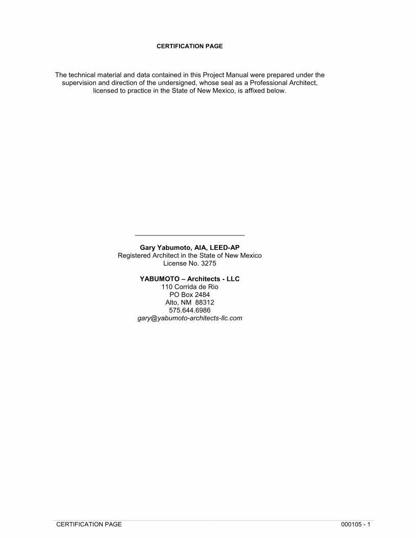
CERTIFICATION PAGE
The technical material and data contained in this Project Manual were prepared under thesupervision and direction of the undersigned, whose seal as a Professional Architect,
licensed to practice in the State of New Mexico, is affixed below.
_____________________________
Gary Yabumoto, AIA, LEED-APRegistered Architect in the State of New Mexico
License No. 3275
YABUMOTO – Architects - LLC110 Corrida de Rio
PO Box 2484Alto, NM 88312575.644.6986

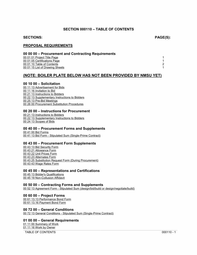
TABLE OF CONTENTS 000110 - 1
SECTION 000110 – TABLE OF CONTENTS
SECTIONS: PAGE(S):
PROPOSAL REQUIREMENTS
00 00 00 – Procurement and Contracting Requirements00 01 01 Project Title Page 100 01 05 Certifications Page 100 01 10 Table of Contents 200 01 15 List of Drawing Sheets 1
(NOTE: BOILER PLATE BELOW HAS NOT BEEN PROVIDED BY NMSU YET)
00 10 00 – Solicitation00 11 13 Advertisement for Bids00 11 16 Invitation to Bid00 21 13 Instructions to Bidders00 22 13 Supplementary Instructions to Bidders00 25 13 Pre-Bid Meetings00 26 00 Procurement Substitution Procedures
00 20 00 – Instructions for Procurement00 21 13 Instructions to Bidders00 22 13 Supplementary Instructions to Bidders00 24 13 Scopes of Bids
00 40 00 – Procurement Forms and Supplements00 41 00 Bid Forms00 41 13 Bid Form - Stipulated Sum (Single-Prime Contract)
00 43 00 – Procurement Form Supplements00 43 13 Bid Security Form00 43 21 Allowance Form00 43 22 Unit Prices Form00 43 23 Alternates Form00 43 25 Substitution Request Form (During Procurement)00 43 43 Wage Rates Form
00 45 00 – Representations and Certifications00 45 13 Bidder's Qualifications00 45 19 Non-Collusion Affidavit
00 50 00 – Contracting Forms and Supplements00 52 13 Agreement Form - Stipulated Sum (design/bid/build or design/negotiate/build)
00 60 00 – Project Forms00 61 13.13 Performance Bond Form00 61 13.16 Payment Bond Form
00 72 00 – General Conditions00 72 13 General Conditions - Stipulated Sum (Single-Prime Contract)
01 00 00 – General Requirements01 11 00 Summary of Work01 11 16 Work by Owner
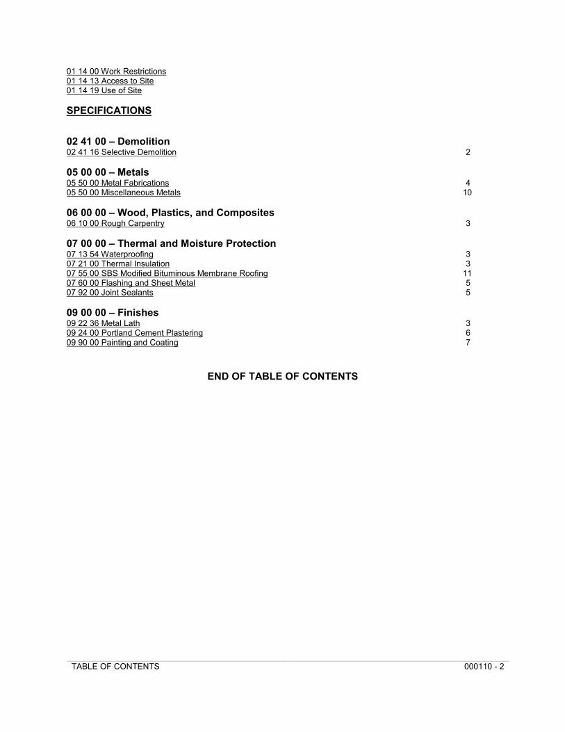
TABLE OF CONTENTS 000110 - 2
01 14 00 Work Restrictions01 14 13 Access to Site01 14 19 Use of Site
SPECIFICATIONS
02 41 00 – Demolition02 41 16 Selective Demolition 2
05 00 00 – Metals05 50 00 Metal Fabrications 405 50 00 Miscellaneous Metals 10
06 00 00 – Wood, Plastics, and Composites06 10 00 Rough Carpentry 3
07 00 00 – Thermal and Moisture Protection07 13 54 Waterproofing 307 21 00 Thermal Insulation 307 55 00 SBS Modified Bituminous Membrane Roofing 1107 60 00 Flashing and Sheet Metal 507 92 00 Joint Sealants 5
09 00 00 – Finishes09 22 36 Metal Lath 309 24 00 Portland Cement Plastering 609 90 00 Painting and Coating 7
END OF TABLE OF CONTENTS
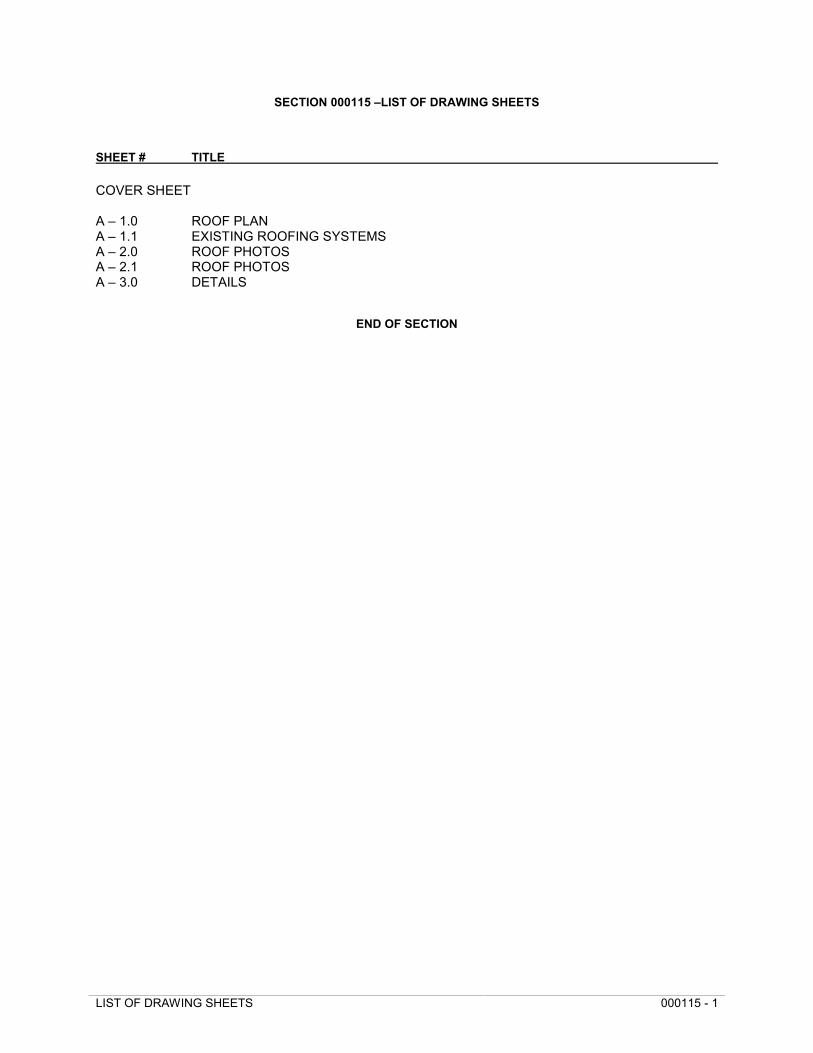
LIST OF DRAWING SHEETS 000115 - 1
SECTION 000115 –LIST OF DRAWING SHEETS
SHEET # TITLE
COVER SHEET
A – 1.0 ROOF PLANA – 1.1 EXISTING ROOFING SYSTEMSA – 2.0 ROOF PHOTOSA – 2.1 ROOF PHOTOSA – 3.0 DETAILS
END OF SECTION

SELECTIVE DEMOLITION 024116 - 1
SECTION 024116 – SELECTIVE DEMOLITION
PART 1 - GENERAL
1.1 DESCRIPTION
A. Work included: Carefully demolish and remove from the site those items scheduled to be sodemolished and removed.
1.2 QUALITY ASSURANCE
A. Use adequate numbers of skilled workers who are thoroughly trained and experienced in thenecessary crafts and who are completely familiar with the specified requirements and the methodsneeded for proper performance of the work of this Section.
1.3 PRODUCT HANDLING
A. Comply with pertinent provisions of Section 013100-Project Management and Coordination.
PART 2 - PRODUCTS
(No products are required in this Section).
PART 3 - EXECUTION
3.1 SURFACE CONDITIONS
A. Examine the areas and conditions under which work of this Section will be performed. Correctconditions detrimental to timely and proper completion of the Work. Do not proceed untilunsatisfactory conditions are corrected.
3.2 DEMOLITION
A. By careful study of the Contract Documents, determine the location and extent of selectivedemolition to be performed.
B. In company with the Architect, visit the site and verify the extent and location of selective demolitionrequired.
1. Carefully identify limits of selective demolition.
2. Make interface surfaces as required to enable workers also to identify items to beremoved and items to be left in place intact.
C. Prepare and follow an organized plan for demolition and removal of items.
1. Shut off, cap, and otherwise protect existing public utility lines in accordance with therequirements of the public agency or utility having jurisdiction.
2. Completely remove items scheduled to be so demolished and removed, leaving surfacesclean, solid, and ready to receive new materials specified elsewhere.
3. In all activities, comply with pertinent regulations of governmental agencies havingjurisdiction.
D. Demolished material shall be considered to be property of the Contractor (except for items noted inparagraph 3.4) and shall be completely removed from the job site.
E. Use means necessary to prevent dust becoming a nuisance to the public, to neighbors, and toother work being performed on or near the site.
F. Salvage items for reuse as noted on the plans.

SELECTIVE DEMOLITION 024116 - 2
3.3 REPLACEMENTS
A. In the event of demolition of items not so scheduled to be demolished, promptly replace such itemsto the approval of the Architect and at no additional cost to the Owner.
3.4 SALVAGE
A. Items which will be salvaged and turned over to the Owner or reinstalled in this project include thefollowing:
1. Items as shown or noted in the drawings.
- END OF SECTION -
METAL FABRICATIONS 055000 - 1
SECTION 055000 - METAL FABRICATIONS
PART 1 - GENERAL
1.1 SUMMARY
A. Section includes:
1. Steel ladders providing interior access to roof.
2. Brackets and supports for countertops and wall and ceiling mounted equipment.
3. Steel pipe and tubular handrails and guard railings.
4. Exterior door pedestals for mounting door stops, push plate door operators, and card readers.
B. Related sections:
1. Section 05120 - Structural Steel: Anchor bolts, bearing plates, splice plates, angle bracing, andother structural components and fabrications.
2. Section 09900 - Painting: Field painting of metal fabrications.
1.2 REFERENCE STANDARDS
A. American National Standards Institute (ANSI):
1. ANSI A14.3 - Ladders, Fixed, Safety Requirements.
2. ANSI A202.1 - Metal Bar Grating Manual for Steel and Aluminum Gratings and Stair Treads.
B. American Society for Testing and Materials (ASTM) Publications:
1. ASTM A36 - Structural Steel.
2. ASTM A283 - Carbon Steel Plates, Shapes, and Bars.
3. ASTM A307 - Carbon Steel Bolts and Studs, 60,000 psi Tensile Strength.
4. ASTM A500 - Cold-Formed Welded and Seamless Carbon Steel Structural Tubing in Rounds andShapes.
5. ASTM A501 - Hot-Formed Welded and Seamless Carbon Steel Structural Tubing.
6. ASTM E985 - Permanent Railing Systems and Rails for Buildings.
C. American Welding Society (AWS) Publications:
1. AWS A2.0 - Standard Welding Symbols.
2. AWS D1.1 - Structural Welding Code.
D. Steel Structures Painting Council (SSPC):
1. Steel Structures Painting Manual.
1.3 SUBMITTALS
A. Submit in accordance with Section 01330 - Submittal Procedures:
1. Shop drawings:
a. Indicate profiles, sizes, connections, size and type of fasteners, accessories, and fabricationand erection details.
METAL FABRICATIONS 055000 - 2
b. Indicate welded connections using standard AWS A2.0 welding symbols. Include weldlength.
PART 2 - PRODUCTS
2.1 MATERIALS FOR STEEL FABRICATIONS
A. Steel sections: ASTM A36.
B. Steel tubing: ASTM A500, Grade B and ASTM A501.
C. Steel pipe: ASTM A53, Type B, Schedule 40.
D. Shop and touch-up primer: SSPC 15, Type 1, red oxide.
2.2 CONNECTION MATERIALS
A. Welding materials: AWS D1.1; type required for materials being welded.
B. Bolts, nuts, and washers: ASTM A307:
2.3 GENERAL FABRICATION
A. Field verify dimensions prior to fabrication.
B. Fabricate interfacing parts and assemblies so that field cutting adjustments are not necessary.
C. Shop fit and assemble in the largest practical sections for delivery to site.
D. Grind exposed welds flush and smooth with adjacent finished surface. Ease exposed edges to smalluniform radius.
E. Make exposed joints butt, flush, and hairline.
F. Supply components required for anchorage of metal fabrications. Fabricate anchorage and relatedcomponents of same material and finish as metal fabrication, unless otherwise indicated.
G. Provide sleeves, inserts, and bolts required for attachment of fabricated and miscellaneous steel items.
2.4 LADDERS
A. Comply with ANSI A14.3.
B. Side rails: 3 inches by 1/4 inch continuous flat bar with eased edges. Space rails 20 inches apart.
C. Rungs: 1 inch diameter steel pipe. Space 12 inches on center. Provide non-slip surface on top ofrungs with aluminum oxide granules set in epoxy resin adhesive.
D. Support ladder at top and bottom and at 5 feet maximum intermediate points with welded or boltedsteel brackets. Allow 7 inches clearance from wall to center line of rungs.
E. Interior ladder to roof hatch: Coordinate height with design of roof hatch and depth of curb. Extendrails of interior ladder above top rung and return rails to wall or structure.
2.5 RAILINGS
A. Railings and attachments shall be fabricated and installed in accordance with ASTM E985 to support:
1. 200 pounds concentrated loading applied at any point in any direction.
2. 50 pounds per linear foot uniform load applied horizontally to top of rail.
B. Pipe railings:
1. Rails and posts: 1-1/4 inches diameter steel pipe or as otherwise indicated on Drawings.
2. Provide 1-1/4 inches diameter intermediate rails spaced as indicated on Drawings.
METAL FABRICATIONS 055000 - 3
3. Door safety guardrails: U-shaped guard rails for outward swinging exterior entrance doorsfabricated from 1-1/2 inches diameter steel pipe, 42 inches long and 30 inches high exposeddimensions. Allow for 10 inches minimum embedment in concrete footing.
C. Form railings to designs shown on Drawings with all turns and easements. Use flush fittings with fullwelded connections for elbows, wall returns, and end caps. Form joints at tees and crosses withwelded flush type fittings or by notching ends to fit contour of pipe and welding. Welds to becontinuous and dressed smoothly.
D. Wall brackets, escutcheons and other fittings: Cast steel.
E. Mountings:
1. Masonry: Embedded steel brackets.
2. Concrete: Steel sleeves.
3. Stud partitions: Backing plates.
2.6 STEEL BOLLARDS
A. Steel bollard shall be fabricated from one piece new steel conforming to A-53, schedule 40, Grade B,to the dimensions shown on the Drawings.
B. Concrete Fill per Section 03001 Concrete.
C. Painting Per Section 09900, Painting.
2.7 SHOP FINISHING
A. Surface preparation: Clean surfaces of rust, scale, grease, and foreign matter.
B. Do not prime surfaces in direct contact with concrete or where field welding is required.
C. Prime paint specified items with one coat minimum 2 mils dry film thickness.
D. Finish: Hot dipped galvanized with epoxy enamel top coat. Color selected from manufacturer'sstandard range.
PART 3 - EXECUTION
3.1 PREPARATION
A. All welding shall conform to requirements of AWS D1.1. Tack welds are prohibited on exposedsurfaces.
B. Provide washers where shown; tighten nuts and nick threads to prevent loosening of bolts.
C. Provide holes and connections for work of other trades.
D. Do not cut sections of structure including flanges, webs, plates, or angles without written permission ofArchitect, or unless shown on Drawings.
3.2 ERECTION
A. Weld or bolt as indicated, complying with details of approved shop drawings.
B. Provide temporary bracing and fasteners to hold parts until attachment is complete.
C. After installation, touch-up damaged surfaces: For shop-primed surfaces use same type primer. Applycoat of primer to all uncoated nuts, bolts, and other steel items installed without shop-applied primer.
3.3 EMBEDDED ITEMS
METAL FABRICATIONS 055000- 4
A. Embed bike racks, door pedestals, and door safety guardrails in concrete footing as detailed onDrawings and approved shop drawings door guard rails.
B. For door pedestals supporting automatic door push plates and card readers coordinate requirementsand allow for installation of conduit and wiring.
C. Set in 12 inches diameter by 20 inches deep minimum footing. Embed pipe 10 inches minimum.
D. Where concrete slab is cast around embedded pipe provide compressible joint material to providebond breaker.
E. Set in 12 inches diameter by 20 inches deep footing. Embed pipe 16 inches minimum.
END OF SECTION
MISCELLANEOUS METALS 055000 - 1
SECTION 055000MISCELLANEOUS METALS
PART 1 GENERAL
1.1 GENERAL REQUIREMENTS
A. Work of this Section, as shown or specified, shall be in accordance with the requirementsof the Contract Documents.
1.2 SECTION INCLUDES
A. Work of this Section includes all labor, materials, equipment, and services necessary to completethe miscellaneous metal work as indicated on the drawings and/or specified herein including, butnot limited to, the following:
1. Rough hardware.
2. Vertical steel ladders and ship’s ladders.
3. Folding ship’s ladder (wall ladder).
4. Open riser steel spiral stairs.
5. Steel pipe handrails and railings not part of steel pan stair assemblies.
6. Light steel framing and supports, not included as part of work of other trades.
7. Steel gratings and frames.
8. Elevator divider beams, guide rail beams and elevator pit hold down beams.
9. Steel bollards.
10. Miscellaneous steel trim, corner guards, angle guards and channels.
11. Sleeves in concrete walls and slabs.
12. Site gate.
13. “Strong-eye”.
14. Exterior rigging tree.
15. Steel framing, bracing, supports, anchors, bolts, shims, fastenings, and all othersupplementary parts indicated on drawings or as required to complete each item of work ofthis Section.
16. Prime painting, touch-up painting, galvanizing and separation of dissimilar metals for work ofthis Section.
17. Cutting, fitting, drilling and tapping work of this Section to accommodate work of otherSections and of concrete, masonry or other materials as required for attaching and installingwork of this Section.
1.3 RELATED SECTIONS
A. Structural steel — Section 051200.
B. Steel pan stairs — Section 055100.
C. Painting — Section 099000.
MISCELLANEOUS METALS 055000 - 2
1.4 QUALITY ASSURANCE
A. Field Measurements: Take field measurements prior to preparation of shop drawings andfabrication, where possible. Do not delay job progress; allow for trimming and fitting wheretaking field measurements before fabrication might delay work.
B. Shop Assembly: Pre-assemble items in shop to greatest extent possible to minimize field splicingand assembly. Disassemble units only as necessary for shipping and handling limitations. Clearlymark units for re-assembly and coordinated installation.
C. Reference Standards: The work is subject to requirements of applicable portions of the followingstandards:
1. “Manual of Steel Construction,“ American Institute of Steel Construction.
2. AWS D1-1 “Structural Welding Code,“ American Welding Society.
3. SSPC SP-3 “Surface Preparation Specification No. 3, Power Tool Cleaning,“ SteelStructures Painting Council.
4. SSPC PA-1 ”Painting Application Specification,” Steel Structures PaintingCouncil.
5. ”Handbook on Bolt, Nut and Rivet Standards,” Industrial Fasteners Institute.
D. Steel Materials: For steel to be hot dip-galvanized, provide steel chemically suitable for metalcoatings complying with the following requirements: carbon below 0.25 percent, silicon below0.24 percent, phosphorous below 0.05 percent, and manganese below 1.35 percent. Notifygalvanizer if steel does not comply with these requirements to determine suitability forprocessing.
E. Engage the services of a galvanizer who has demonstrated a minimum of five (5) years’experience in the successful performance of the processes outlined in this specification in thefacility where the work is to be done and who will apply t h e galvanizing and coatings within thesame facility as outlined herein. The Architect has the right to inspect and approve or reject thegalvanizer/galvanizing facility.
F. The galvanizer/galvanizing facility must have an ongoing Quality Control/Quality Assuranceprogram which has been in effect for a minimum of five years and shall provide the Architectwith process and final inspection documentation. T h e galvanizer/galvanizing facility must havean on-premise testing facility capable of measuring the chemical and metallurgical composition ofthe galvanizing bath and pickling tanks.
G. Inspection and testing of hot-dip galvanized coating shall be done under t h e guidelinesprovided in the American Hot-Dip Galvanizers Association (AGA) publication ”Inspection ofProducts Hot-Dip Galvanized After Fabrication.”
1.5 PERFORMANCE STANDARDS
A. Stairs and railings shall be constructed to conform to the following performance standards:
1. Stairs and platforms shall support a live load of one hundred (100) psf and a concentratedlive load of three hundred (300) lbs. and shall have a live load deflection limited to 1/360 ofthe span. Loads shall not apply simultaneously.
2. Railings shall be designed to resist loads per State of New Mexico Building Code.
1.6 SUBMITTALS
A. Manufacturer’s Literature: Submit manufacturer’s specifications, load tables, dimensiondiagrams, anchor details and installation instructions for products to be used in the fabrication of
MISCELLANEOUS METALS 055000 - 3
miscellaneous metal work, including paint products.
B. Shop Drawings: Shop drawings for the fabrication and erection of all assemblies of miscellaneousiron work which are not completely shown by manufacturer’s data sheets. Include plans andelevations at not less than 1” to 1’-0” scale, and include details of sections and connections atnot less than 3” to 1’-0” scale. Show anchorage and accessory items.
C. Engineering Data
1. Before any stairs, ladders and railings are fabricated, submit engineering data drawings tothe Architect for review indicating how performance standards specified here shall be met.The Contractor is responsible for the structural design and supports for these systems andmust show his proposed systems on these drawings.
2. These drawings must show all load conditions and design calculations relative toconnections, fastening devices and anchorage, as well as size and gauge of members.Calculations and drawings must be prepared by a Structural Engineer licensed in the Stateof New Mexico and shall be signed and sealed by this Engineer.
D. Welding shall be indicated on shop drawings using AWS symbols and showing length, size andspacing (if not continuous). Auxiliary views shall be shown to clarify all welding. Notes such as1/4” weld, weld and tack weld are not acceptable.
E. Certification: For items to be hot-dip galvanized, identify each item galvanized and to showcompliance of application. The Certificate shall be signed by t h e galvanizer and shall contain adetailed description of the material processed and t h e ASTM standard used for the coating and,the weight of the coating. In addition, and as attachment to Certification, submit reports of testingand inspections indicating compliance with the provisions of this Section.
PART 2 PRODUCTS
2.1 MATERIALS
A. Metals
1. Metal Surfaces, General: For fabrication of miscellaneous metal work which will beexposed to view, use only materials which are smooth and free of surface blemishesincluding pitting, seam marks, roller marks, rolled trade names and roughness.
2. Steel Plates, Shapes and Bars: ASTM A 36.
3. Steel Bar Grating: ASTM A 1011/A or ASTM A 36.
4. Steel Tubing: Cold formed, ASTM A 500; or hot rolled, ASTM A 501.
5. Structural Steel Sheet: Hot rolled, ASTM A 570; or cold rolled, ASTM A 611, Class 1; ofgrade required for design loading.
6. Galvanized Structural Steel Sheet: ASTM A 924, of grade required for design loading.Coating designation G90.
7. Steel Pipe: ASTM A 53, type and grade as selected by fabricator and as required fordesign loading; black finish unless galvanizing is indicated; standard weight (Schedule 40),unless otherwise indicated.
8. Gray Iron Castings: ASTM A 48, Class 30, unless another class is indicated or required bystructural loads.
9. Malleable Iron Castings: ASTM A 47, grade as selected by fabricator.
10. Brackets, Flanges and Anchors: Cast or formed metal of the same type material and
MISCELLANEOUS METALS 055000 - 4
finish as supported rails, unless otherwise indicated.
11. Concrete Inserts: Threaded or wedge type; galvanized ferrous castings, either malleableiron, ASTM A 47, or cast steel, ASTM A 27. Provide bolts, washers and shims as required,hot-dip galvanized, ASTM A 153.
B. Grout: Non-shrink, non-metallic grout conforming to the requirements of Section033000.
C. Fasteners
1. General: Provide zinc-coated fasteners for exterior use or where built into exterior walls.Select fasteners for the type, grade and class required.
2. Bolts and Nuts: Regular hexagon head type, ASTM A 307, Grade A.
3. Anchor Bolts: ASTM F 1554, Grade 36.
4. Lag Bolts: ASME B18.2.1.
5. Machine Screws: ASME B18.6.3.
6. Plain Washers: Round, carbon steel, ASME B18.22.1.
7. Masonry Anchorage Devices: Expansion shields, FS FF-S-325.
8. Toggle Bolts: Tumble-wing type, FS FF-B-588, type, class and style as required.
9. Lock Washers: Helical spring type carbon steel, ASME B18.21.1.
D. Shop Paint: Shop prime all non-galvanized miscellaneous metal items using Series88 Azeron Primer made by Tnemec, ICI Devoe “Rust Guard“ quick dry alkyd shop coat No.41403, or “Interlac 393“ by International Protection Coatings.
1. If steel is to receive high performance coating as noted in Section 099000, shop prime usingprimer noted in Section 099000.
E. Bituminous Paint: Cold applied asphalt emulsion complying with ASTM D 1187.
F. Galvanize Repair Coating: For touching up galvanized surfaces after erection, provide repaircoating that is V.O.C. compliant, equal to “Silver Galv“ made by Z.R.C. Worldwide or approvedequal. Apply to a dry film thickness of 1.5 to 3.0 mils.
2.2 PRIME PAINTING
A. Scope: All ferrous metal (except galvanized steel) shall be cleaned and shop painted with onecoat of specified ferrous metal primer. No shop prime paint required on galvanized steel oraluminum work.
B. Cleaning: Conform to Steel Structures Painting Council Surface Preparation SpecificationSP 3 (latest edition) “Power Tool Cleaning“ for cleaning of ferrous metals which are to receiveshop prime coat.
1. Steel to get high performance coating as noted in Section 099000 shall be cleaned as perSSPC SP.6 “Commercial Blast Cleaning.“
C. Application
1. Apply shop prime coat immediately after cleaning metal. Apply paint in dry weather orunder cover. Metal surfaces shall be free from frost or moisture when painted. Paint allmetal surfaces including edges, joints, holes, corners, etc.
2. Paint surfaces which will be concealed after shop assembly prior to such assembly.
MISCELLANEOUS METALS 055000 - 5
Apply paint in accordance with approved paint manufacturer’s printed instructions, and theuse of any thinners, adulterants or admixtures shall be only as stated in said instructions.
3. Paint shall uniformly and completely cover the metal surfaces, 2.0 mils minimum dryfilm thickness. No work shall be shipped until the shop prime coat thereon has dried.
D. Touch-Up: In the shop, after assembly and in the field, after installation of work of this Section,touch-up damaged or abraded portions of shop prime paint with specified ferrous metal primer.
E. Apply one shop coat to fabricated metal items, except apply two (2) coats of paint to surfacesinaccessible after assembly or erection. Change color of second coat to distinguish it from thefirst.
2.3 GALVANIZING
A. Scope: All ferrous metal exposed to the weather, and all ferrous metals indicated on drawings orin specifications to be galvanized, shall be cleaned and then hot-dipped galvanized afterfabrication as provided by Duncan Galvanizing or approved equal.
B. Avoid fabrication techniques that could cause distortion or embrittlement of steel items to be hot-dip galvanized. Fabricator shall consult with hot-dip galvanizer regarding potential warpageproblems or handling problems during the galvanizing process that may require adjustment offabrication techniques or design before finalizing shop drawings and beginning of fabrication.
C. Cleaning: Thoroughly clean metal surfaces of all mill scale, rust, dirt, grease, oil, moisture andother contaminants prior to galvanizing.
D. Application: Hot-dip galvanizing shall be applied in accordance with:
1. ASTM A 143: Safeguarding Against Embrittlement of Hot-Dip GalvanizedStructural Steel.
2. ASTM A 123: Standard Specification for Zinc (Hot-Dip Galvanized) Coatings on Iron andSteel Products.
3. ASTM A 153: Galvanized Coating on Iron and Steel Hardware - Table 1.
4. ASTM A 385: Practice for Providing High Quality Zinc Coatings.
5. ASTM A 924: Galvanized Coating on Steel Sheets.
6. Minimum weight of galvanized coating shall be two (2) oz. per square foot of surface.
E. Fabricate joints which will be exposed to weather in a manner to exclude water or provide weepholes where water may accumulate.
F. All galvanized materials must be inspected for compliance with these specifications and markedwith a stamp indicating the name of the galvanizer, the weight of t h e coating, and the appropriateASTM number.
G. To minimize surface imperfection (eg: flux inclusions), material to be galvanized shall be dippedinto a solution of Zinc Ammonium Chloride (pre-flux) immediately prior to galvanizing. The typeof galvanizing process utilizing a flux blanket overlaying the molten zinc will not be permitted.
H. After galvanizing all materials not exposed to view must be chromated by dipping material in a0.2% chromic acid solution.
I. Galvanized surfaces, where exposed to view, must have a smooth, level surface finish. Where thisdoes not occur, piece shall be rejected and replaced to t h e acceptance of the Architect.
2.4 PROTECTIVE COATINGS
MISCELLANEOUS METALS 055000 - 6
A. Whenever dissimilar metals will be in contact, separate contact surfaces by coating each contactsurface prior to assembly or installation with one coat of specified bituminous paint, whichshall be in addition to the specified shop prime paint. Mask off those surfaces not required toreceive protective coating.
2.5 WORKMANSHIP
A. General
1. Miscellaneous metal work shall be fabricated by an experienced fabricator or manufacturerand installed by an experienced tradesman.
2. Materials, methods of fabrication, fitting, assembly, bracing, supporting, fastening,operating devices, and erection shall be in accordance with drawings and specifications,approved shop drawings, and best practices of the industry, using new and cleanmaterials as specified, having structural properties sufficient to safely sustain orwithstand stresses and strains to which materials and assembled work will be subjected.
3. All work shall be accurately and neatly fabricated, assembled and erected.
B. Shop Assembly: Insofar as practicable, fitting and assembly of work shall be done in shop. Shopassemble work in largest practical sizes to minimize field work. It is t h e responsibility of themiscellaneous metal subcontractor to assure himself that the shop-fabricated miscellaneous metalitems will properly fit the field condition. In the event that shop-fabricated miscellaneous metalitems do not fit the field condition, the item shall be returned to the shop for correction.
C. Cutting: Cut metal by sawing, shearing or blanking. Flame cutting will be permitted only if cutedges are ground back to clean, smooth edges. Make cuts accurate, clean, sharp and free ofburrs, without deforming adjacent surfaces or metals.
D. Holes: Drill or cleanly punch holes; do not burn.
E. Connections: Make connections with tight joints, capable of developing full strength ofmember, flush unless indicated otherwise, formed to exclude water where exposed to weather.Locate joints where least conspicuous. Unless indicated otherwise, weld or bolt shop connections;bolt or screw field connections. Provide expansion and contraction joints to allow for thermalmovement of metal a t locations and by methods approved by Architect.
1. Welding
a. Shall be in accordance with “Standard Code for Welding in Building Construction“of the American Welding Society, and shall be done with electrodes and/or methodsrecommended by the manufacturer of t h e metals being welded.
b. Welds shall be continuous, except where spot welding is specifically permitted. Weldsexposed to view shall be ground flush and dressed smooth with and to matchfinish of adjoining surfaces; undercut metal edges where welds are required to beflush.
c. All welds on or behind surfaces which will be exposed to view shall be done so as toprevent distortion of finished surface. Remove weld spatter and welding oxides fromall welded surfaces.
2. Bolts and Screws: Make threaded connections tight with threads entirely concealed. Uselock nuts. Bolts and screw heads exposed to view shall be flat and countersunk. Cut offprojecting ends of exposed bolts and screws flush with nuts or adjacent metal.
F. Operating Mechanism: Operating devices (i.e. pivots, hinges, etc.) mechanism and hardwareused in connection with this work shall be fabricated, assembled, installed and adjusted afterinstallation so that they will operate smoothly, freely, noiselessly and without excessive friction.
MISCELLANEOUS METALS 055000 - 7
G. Built-In Work: Furnish anchor bolts, inserts, plates and any other anchorage devices, and allother items specified under this Section of the Specifications to be built into concrete, masonry orwork of other trades, with necessary templates and instructions, and in ample time to facilitateproper placing and installation.
H. Supplementary Parts: Provide as necessary to complete each item of work, even though suchsupplementary parts are not shown or specified.
I. Coordination: Accurately cut, fit, drill and tap work of this Section to accommodate and fitwork of other trades. Furnish or obtain, as applicable, templates and drawings to or fromapplicable trades for proper coordination of this work.
J. Exposed Work
1. In addition to requirements specified herein and shown on drawings, all surfaces exposed toview shall be clean and free from dirt, stains, grease, scratches, distortions, waves, dents,buckles, tool marks, burrs, and other defects which mar appearance of finished work.
2. Metal work exposed to view shall be straight and true to line or curve, smooth arrises andangles as sharp as practicable, miters formed in true alignment, profiles accuratelyintersecting, and with joints carefully matched to produce continuity of line and design.
3. Exposed fastenings, where permitted, shall be of the same material, color and finish as themetal to which applied, unless otherwise indicated, and shall be of the smallest practicablesize.
K. Preparation for Hot-Dip Galvanizing: Fabricator shall correctly prepare assemblies forgalvanizing in consultation with galvanizer and in accordance with applicable ReferenceStandards and applicable AGA publications for the “Design of Products to be Hot-Dip galvanizedAfter Fabrication.“ Preparation shall include but not be limited to the following:
1. Remove welding flux.
2. Drill appropriate vent holes and provide for drainage in inconspicuous locations ofhollow sections and semi-enclosed elements. After galvanizing, plug vent holes with shapedlead and grind smooth.
2.6 MISCELLANEOUS METALS ITEMS
A. Rough Hardware
1. Furnish bent or otherwise custom fabricated bolts, plates, anchors, hangers, dowels andother miscellaneous steel and iron shapes as required for framing and supporting woodwork,and for anchoring or securing woodwork to concrete or other structures. Straight bolts andother stock rough hardware items are specified in Division 6 Sections.
2. Fabricate items to sizes, shapes and dimensions required. Furnish malleable iron washersfor heads and nuts which bear on wood connections; elsewhere, furnish steel washers.
B. Ladders
1. Vertical steel ladders shall be eighteen (18) inches wide with 3/4” diameter non-slip steelrungs spaced twelve (12) inches o.c. Stringers shall be 3/8” thick by 2-1/2” wide steel bars;rungs welded to bars. Attach ladders to walls six (6) inches from top and bottom andmaximum thirty-six (36) inches o.c. from these points.
2. Provide sloping ladders (ship’s ladders) where noted. Fabricate open type constructionwith structural steel channel or steel plate stringers, pipe handrails, and open steelgrating treads. Provide all necessary brackets and fittings for installation.
MISCELLANEOUS METALS 055000 - 8
3. Ladders shall be fabricated to support a live load of one hundred (100) lbs. per square footand a concentrated load of three hundred (300) lbs. per rung; loads not to actsimultaneously.
C. Folding Ship’s Ladder (Wall Ladder): “Model 465 — 70° Mezzanine Access Folding Wall Ladder”by ALACO Ladder CO., or approved equal.
1. Height: As indicated on drawings.
2. Width: 24”
3. Finish: Mill finish aluminum. D.
Spiral Stair
1. Provide metal fully assembled spiral stairs by Stairways Inc., or approved equal.
2. Fabricate spiral stair and rails of hot dip galvanized steel. a.
Treads shall be No. 133 galvanized steel radial grate.b. Railings shall be No. 312, 1/2” square galvanized steel.
3. Stair and railing shall be fabricated and installed to meet Code and performancerequirements.
E. Steel Pipe Handrails
1. Steel pipe of size shown on Drawings, Schedule 40. Fittings shall be flush type, malleable ofcast iron. Brackets shall be malleable iron, design as selected by the Architect.
2. Construction: Form direction changes in rails using solid bar stock or elbows.Connections shall be shop welded and ground smooth and flush, except where fieldconnections and expansion joints are required. Field connections may be welded, internalsleeve and plug weld, or internal sleeve and set screw.
3. Secure handrails to walls with wall brackets. Provide brackets of malleable iron castings withnot more than three (3) inches clearance from inside face of handrail to wall surface. Neatlydrill wall plate portion of the bracket into concrete or masonry to receive bolts for concealedanchorage. For installation at drywall, Drywall trades shall provide plate to receive wallplate portion of bracket and anchor or bolt wall plate through drywall to supporting steelplate. Locate brackets at not more than 5’-0” o.c. unless otherwise shown.
4. Provide wall return fittings of cast iron, flush type, with the same projection as that specifiedfor wall brackets.
5. Longitudinal members shall be parallel with each other and with floor surface or shape ofstair to a tolerance of 1/8” in 10’-0” linear feet. Center line of members within each runof railing shall be in the plane.
6. For steel pipe posts where indicated, anchor posts in concrete by means of pipe sleeves setand anchored into concrete. Provide sleeves of galvanized steel pipe, not less than six(6) inches long and having an inside diameter not less than 1/2” greater than outsidediameter of the inserted pipe. Provide steel plate closure secure to bottom of sleeve andof width and length not less than one (1) inch greater than outside diameter of sleeve. Afterposts have been inserted into sleeves, fill annular space between post and sleeve solid withnon- shrink, non-ferrous grout. Cover anchorage joint with a round steel flange welded topost. Posts shall be set plumb within 1/8” vertical tolerance.
7. Steel pipe handrails shall be capable of resisting a two hundred (200) lb. force applied to railfrom any direction and a uniformly distributed load of fifty (50) lbs. per linear foot applieddownward or horizontally, loads not to act simultaneously.
MISCELLANEOUS METALS 055000 - 9
F. Miscellaneous Light Steel Framing
1. Light steel framing, bracing, supports, framing, clip angles, shelf angles, plates, etc., shall beof such shapes and sizes as indicated on the drawings and details or as required to suitthe condition and shall be provided with all necessary supports and reinforcing suchas hangers, braces, struts, clip angles, anchors, bolts, nuts, welds, etc., as required toproperly support and rigidly fasten and anchor same in place and to steel, concrete,masonry and all other connecting and adjoining work.
2. All light steel framing steel shall be furnished and erected in accordance with the applicablerequirements of the ”Specifications for the Design, Fabrication and Erection of StructuralSteel for Buildings” by the American Institute of Steel Construction and as specified herein.
G. Steel Bollards: Provide six (6) inches O.D. extra strong (Schedule 80) steel pipe, concrete filled,with base of steel plate for mounting to anchor bolts in concrete foundation. Rabbet top of steelpipe and insert 1/4” steel plate cap, flush with t o p of pipe. Weld top of cap to pipe and grindsmooth and flush.
H. Sleeves in Concrete Walls and Slabs
1. Sleeves through concrete walls shall be of Schedule 40 steel pipe with i.d. two (2) incheslarger than o.d. of pipe or conduit (including insulation, if any) to be accommodated. Sleevesshall project one-half (1/2) inch on each side of finished wall. Provide rectangular one-quarter (1/4) inch steel plate collar at center, continuously welded to the perimeter of thesleeve, and six (6) inches wider than the o.d.
2. Slots in slabs shall be 12 gauge steel sheet, galvanized, of dimensions indicated, with strapanchors welded in place not more than twelve (12) inches on centers.
PART 3 EXECUTION
3.1 INSPECTION
A. Examine the areas and conditions where miscellaneous metal is to be installed and correct anyconditions detrimental to the proper and timely completion of t h e work. Do not proceedwith the work until unsatisfactory conditions are corrected to permit proper installation of the work.
3.2 ERECTION
A. Fastening to In-Place Construction: Provide anchorage devices and fasteners where necessaryfor securing miscellaneous metal fabrications to in-place construction; including threadedfasteners for concrete and masonry inserts, toggle bolts, through- bolts, lag bolts, wood screws,and other connectors as required.
B. Cutting, Fitting and Placement: Perform cutting, drilling and fitting required for installation ofmiscellaneous metal fabrications. Set work accurately in location, alignment and elevation,plumb, level, true and free of rack, measured from established lines and levels. Providetemporary bracing or anchors in formwork for items which are to be built into concrete, masonry,or similar construction.
C. Fitting Connections: Fit exposed connections accurately together to form light hairline joints.Weld connections which are not to be left as exposed joints, but cannot be shop welded becauseof shipping size limitations. Grind exposed joints smooth and touch up shop paint coat. Do notweld, cut or abrade the surfaces of exterior units which have been hot dip galvanized afterfabrication, and are intended for bolted or screwed field connections.
D. Field Welding: Comply with AWS Code for procedures of manual shielded metal-arcwelding, appearance, and quality of welds made, and methods used in correcting welding
MISCELLANEOUS METALS 055000 - 10
work.
E. Touch-Up Painting: Immediately after erection, clean field welds, bolted connections,and abraded areas of shop paint, and paint exposed areas with same material as used for shoppainting. Apply by brush or spray to provide a minimum dry film thickness of 2.0 mils.
F. Field Touch-Up of Galvanized Surfaces: Touch-up shop applied galvanized coatings damagedduring handling and installation. Use galvanizing repair coating specified herein for galvanizedsurfaces.
3.3 FOLDING WALL LADDER INSTALLATION
A. Establish centerline of mounting bracket on face of mezzanine 3” below floor. B.
Install top step even with floor line.
C. Check clear floor space required at bottom, and install ladder at 70 angular degrees. D.Install in
accordance with manufacturer’s complete installation recommendations.
END OF SECTION
ROUGH CARPENTRY 061000- 1
SECTION 061000 - ROUGH CARPENTRY
PART 1 GENERAL
1.01 SECTION INCLUDES
A. Roof-mounted curbs.
B. Roofing nailers.
C. Preservative treated wood materials.
D. Fire retardant treated wood materials.
E. Miscellaneous framing and sheathing.
F. Concealed wood blocking, nailers, and supports.
1.02 REFERENCE STANDARDS
A. ASTM A 153/A 153M - Standard Specification for Zinc Coating (Hot-Dip) on Iron and Steel Hardware;2005.
B. ASTM E 84 - Standard Test Method for Surface Burning Characteristics of Building Materials; 2008.
C. AWPA C2 - Lumber, Timber, Bridge Ties and Mine Ties -- Preservative Treatment by Pressure Processes;American Wood-Preservers' Association; 2003.
D. AWPA C20 - Structural Lumber -- Fire Retardant Treatment by Pressure Processes; American Wood-Preservers' Association; 2003.
E. AWPA C27 - Plywood -- Fire-Retardant Treatment by Pressure Processes; American Wood-Preservers'Association; 2002.
F. AWPA U1 - Use Category System: User Specification for Treated Wood; American Wood-Preservers'Association; 2007.
G. PS 1 - Structural Plywood; 2007.
H. PS 20 - American Softwood Lumber Standard; National Institute of Standards and Technology(Department of Commerce); 2005.
1.03 DELIVERY, STORAGE, AND HANDLING
A. General: Cover wood products to protect against moisture. Support stacked products to preventdeformation and to allow air circulation.
B. Fire Retardant Treated Wood: Prevent exposure to precipitation during shipping, storage, or installation.
PART 2 PRODUCTS
2.01 GENERAL REQUIREMENTS
A. Dimension Lumber: Comply with PS 20 and requirements of specified grading agencies.1. If no species is specified, provide any species graded by the agency specified; if no grading agency
is specified, provide lumber graded by any grading agency meeting the specified requirements.2. Grading Agency: Any grading agency whose rules are approved by the Board of Review, American
Lumber Standard Committee (www.alsc.org) and who provides grading service for the species andgrade specified; provide lumber stamped with grade mark unless otherwise indicated.
B. Lumber fabricated from old growth timber is not permitted.
2.02 DIMENSION LUMBER FOR CONCEALED APPLICATIONS
A. Sizes: Nominal sizes as indicated on drawings, S4S.
B. Moisture Content: S-dry or MC19.
C. Miscellaneous Framing, Blocking, Nailers, Grounds, and Furring:1. Lumber: S4S, No. 2 or Standard Grade.
ROUGH CARPENTRY 061000- 2
2. Boards: Standard or No. 3.
2.03 CONSTRUCTION PANELS
A. Roof Sheathing: APA PRP-108/APA PRPR-108, Form B455, Structural I Rated Sheathing, ExteriorExposure Class, and as follows:1. Span Rating: 24/0.2. Thickness: 1/2 inch, nominal.
B. Wall Sheathing: APA PRP-108/APA PRP-108, Form B455 Structural I Rated Sheathing, ExteriorExposure Class, and as follows:1. Span Rating: 24/0.2. Thickness: 1/2 inch, nominal.
C. Communications and Electrical Room Mounting Boards: PS 1 A-D plywood, or medium density fiberboard;3/4 inch thick; flame spread index of 25 or less, smoke developed index of 450 or less, when tested inaccordance with ASTM E 84.
D. Other Applications:1. Plywood Concealed From View: PS 1, C-D Plugged or better, Exterior grade.
2.04 ACCESSORIES
A. Fasteners and Anchors:1. Metal and Finish: Hot-dipped galvanized steel per ASTM A 153/A 153M for high humidity and
preservative-treated wood locations, unfinished steel elsewhere.
2.05 FACTORY WOOD TREATMENT
A. Treated Lumber and Plywood: Comply with requirements of AWPA U1 - Use Category System for woodtreatments determined by use categories, expected service conditions, and specific applications.1. Fire-Retardant Treated Wood: Mark each piece of wood with producer's stamp indicating compliance
with specified requirements.2. Preservative-Treated Wood: Provide lumber and plywood marked or stamped by an ALSC-
accredited testing agency, certifying level and type of treatment in accordance with AWPA standards.
B. Fire Retardant Treatment:1. Interior Type A: AWPA Use Category UCFA, Commodity Specification H (Treatment C20 for lumber
and C27 for plywood), low temperature (low hygroscopic) type, chemically treated and pressureimpregnated; capable of providing a maximum flame spread rating of 25 when tested in accordancewith ASTM E 84, with no evidence of significant combustion when test is extended for an additional20 minutes.a. Kiln dry wood after treatment to a maximum moisture content of 19 percent for lumber and 15
percent for plywood.b. Treat rough carpentry items as indicated .c. Do not use treated wood in applications exposed to weather or where the wood may become
wet.
C. Preservative Treatment:1. Preservative Pressure Treatment of Lumber Above Grade: AWPA Use Category UC3B, Commodity
Specification A (Treatment C2) using waterborne preservative to 0.25 lb/cu ft retention.a. Kiln dry lumber after treatment to maximum moisture content of 19 percent.b. Treat lumber in contact with masonry or concrete.
PART 3 EXECUTION
3.01 INSTALLATION - GENERAL
A. Select material sizes to minimize waste.
B. Reuse scrap to the greatest extent possible; clearly separate scrap for use on site as accessorycomponents, including: shims, bracing, and blocking.
C. Where treated wood is used on interior, provide temporary ventilation during and immediately afterinstallation sufficient to remove indoor air contaminants.
3.02 BLOCKING, NAILERS, AND SUPPORTS
ROUGH CARPENTRY 061000- 3
A. Provide framing and blocking members as indicated and as required to support fabrications, finishes,fixtures, specialty items, and trim.
B. In walls, provide blocking attached to studs as backing and support for wall-mounted items, unless itemcan be securely fastened to two or more studs or other method of support is explicitly indicated.
C. Where ceiling-mounting is indicated, provide blocking and supplementary supports above ceiling, unlessother method of support is explicitly indicated.
D. Specifically, provide the following blocking:1. Cabinets and shelf supports.2. Wall brackets.3. Handrails.4. Grab bars.5. Towel and bath accessories.6. Wall-mounted door stops.7. Visual display and marker boards.8. Wall paneling and trim.9. Joints of rigid wall coverings that occur between studs.10. Gymnasium Equipment.11. Windows, doors and storefront openings.12. Other blocking as indicated on Drawings.
3.03 ROOF-RELATED CARPENTRY
A. Coordinate installation of roofing carpentry with deck construction, framing of roof openings, and roofingassembly installation.
B. Provide wood curb at all roof openings except where specifically indicated otherwise. Form corners byalternating lapping side members.
3.04 INSTALLATION OF CONSTRUCTION PANELS
A. Roof Sheathing: Secure panels with long dimension perpendicular to framing members, with endsstaggered and over firm bearing.1. Nail panels to framing; staples are not permitted.
B. Wall Sheathing: Secure with long dimension perpendicular to wall studs, with ends over firm bearing andstaggered, using nails, screws, or staples.
C. Communications and Electrical Room Mounting Boards: Secure with screws to studs with edges over firmbearing; space fasteners at maximum 24 inches on center on all edges and into studs in field of board.1. At fire-rated walls, install board over wall board indicated as part of the fire-rated assembly.2. Where boards are indicated as full floor-to-ceiling height, install with long edge of board parallel to
studs.3. Install adjacent boards without gaps.
END OF SECTION

WATERPROOFING 071354 - 1
SECTION 071354 - WATERPROOFING
PART 1 - GENERAL
1.1 SUMMARY
A. Section includes cold applied self adhered composite sheet waterproofing membrane for below gradeconcrete unit masonry perimeter walls. Includes preparation of surfaces, primer, and protection board.
1.2 SUBMITTALS
A. Provide in accordance with Section 01330 - Submittal Procedures:
1. Product data for waterproofing materials including material safety data sheets.
2. 6 by 6 inches samples of membrane and protection board.
3. Manufacturer's installation instructions and installation details.
1.3 QUALITY ASSURANCE
A. Conditioner, primer, liquid corner flashing, mastic, tape, protection board, and other accessories shallbe compatible with waterproofing membrane and shall be products of a single manufacturer.
1.4 ENVIRONMENTAL REQUIREMENTS
A. Do not apply during inclement weather or when air and surface temperatures are below 25 degrees F.
B. Do not apply concrete and masonry primers when temperature is below 40 degrees F.
C. Protect waterproofing membrane from UV and site damage.
PART 2 - PRODUCTS
2.1 ACCEPTABLE MANUFACTURER
A. Products of the following manufacturers are acceptable and are listed in this Section to establishrequirements for product type, characteristics, performance, and quality:
1. W. R. Grace and Company, Cambridge, Massachusetts; 617-498-4470.
B. Requests to use equivalent products of other manufacturers shall be submitted in accordance withSection 01630 - Product Substitution Procedures.
2.2 WATERPROOFING MATERIALS
A. Conditioner: Water-based surface conditioner; Bituthene System 4000 Surface Conditioner asmanufactured W. R. Grace and Company.
B. Primer: Liquid type water-based latex primer for vertical concrete and masonry surfaces; BitutheneWater-Based Primer as manufactured W. R. Grace and Company.
C. Green concrete primer: Liquid rubber-based solvent primer for green concrete and damp surfaces;
WATERPROOFING 071354 - 2
Bituthene Green Concrete Primer as manufactured W. R. Grace and Company.
D. Waterproofing sheet membrane: Composite sheet membrane consisting of 0.1 mm cross-laminatedpolyethylene film and 1.4 mm self-adhesive rubberized asphalt; Bituthene System 4000 WaterproofingMembrane as manufactured W. R. Grace and Company.
1. Thickness: 1.5 mm.
2. Low temperature flexibility: Unaffected at minus 45 degrees F.
3. Minimum tensile strength:
a. Membrane: 325 pounds per square inch.
b. Film: 5,000 pounds per square inch.
4. Minimum elongation: 300 percent.
5. Lap adhesion: 5.0 pounds per inch of width minimum.
6. Peel strength: 9.0 pounds per inch of width minimum.
7. Minimum puncture resistance: 50 pounds.
8. Resistance of hydrostatic head: 231 feet minimum.
9. Water absorption in 72 hours: 0.1 percent maximum.
E. Liquid waterproofing membrane: Two component cold applied liquid membrane for flashing corners;Bituthene Liquid Membrane as manufactured by W. R. Grace and Company.
F. Mastic: Rubberized asphalt sealant for membrane terminations; Bituthene Mastic as manufactured W.R. Grace and Company.
G. Protection board: 1/2 inch asphalt wood fiberboard.
PART 3 - EXECUTION
3.1 INSPECTION
A. Verify concrete unit masonry retaining walls and concrete foundations are fully cured. Cure concretewalls 7 days minimum.
B. Verify surfaces are solid, free of oil, form release agents, curing compounds, frozen matter, looseparticles, cracks, pits, rough projections, and foreign matter detrimental to adhesion and application ofwaterproofing.
C. Verify items which penetrate surfaces to receive waterproofing are securely installed.
3.2 PREPARATION
A. Clean and prepare surfaces to receive waterproofing in accordance with manufacturer's instructions.
B. Conditioner:
WATERPROOFING 071354 - 3
1. Spray at rate of 330 SF per Gallon.
2. Allow to dry sufficiently so that conditioner cannot be rubbed off.C. Primer:
1. Use special green concrete primer for damp or green substrates. Use water based primer forother conditions.
2. Apply one coat at rate of 500 to 600 SF per gallon.
3. Allow to dry 1 hour minimum. Re-prime prior to application of waterproofing if contaminated bydust or curing time is exceeded.
3.3 MEMBRANE APPLICATION
A. Apply waterproofing in accordance with manufacturer's instructions to basement walls where finishgrade is above finish floor grade.
B. Apply self-adhering waterproofing membrane in maximum lengths up to 8 feet.
C. Lap vertical sides 2-1/2 inches side laps. Lap horizontal ends 2-1/2 inches.
D. Immediately roll membrane with hand roller to ensure full adhesion to primer and adjacent panels.
E. Terminate membrane at grade level. Press membrane firmly to wall with hardwood tool exerting heavypressure.
F. Provide 3/4 inch minimum fillet at juncture of wall and foundation.
G. Double cover outside and inside corners, joints, penetrations, and protrusions with additional 12 inchesstrip of membrane.
H. At locations where sheet membrane is difficult to apply, maintain watertightness with application ofliquid membrane.
I. Apply trowelled bead of mastic at terminations of sheet membrane.
J. After membrane is installed, thoroughly inspect for defects. Patch tears and inadequately lappedseams with sections of membrane. Slit fishmouths and repair with patch extending 6 inches in alldirections from slit and seal edges with mastic.
3.4 INSTALLATION OF PROTECTION BOARD
A. Coordinate installation of protection board with installation of perimeter rigid insulation specified inSection 07210 - Building Insulation.
B. Protect membrane from damage by immediately adhering protection board applied with waterproofingcompound over waterproofing surface. Scribe and cut boards around projections and interruptions.
C. Neatly fit boards tight around pipe and other projections.
D. Backfill against waterproofing and protection board exercising care not to damage system.
END OF SECTION

THERMAL INSULATION 072100 - 1
SECTION 072100 - THERMAL INSULATION
PART 1 GENERAL
1.01 SECTION INCLUDES
A. Board insulation at perimeter foundation wall and as indicated at exterior walls.
B. Batt insulation in exterior wall and ceiling construction.
C. Acoustical batt insulation for interior partitions.
1.02 RELATED REQUIREMENTS
A. Section 07214-Foamed-in-Place Insulation.
1.03 REFERENCE STANDARDS
A. ASTM C 578 - Standard Specification for Rigid, Cellular Polystyrene Thermal Insulation; 2007.
B. ASTM C 665 - Standard Specification for Mineral-Fiber Blanket Thermal Insulation for Light FrameConstruction and Manufactured Housing; 2006.
C. ASTM C 1289 - Standard Specification for Faced Rigid Cellular Polyisocyanurate Thermal Insulation Board;2007.
D. ASTM E 84 - Standard Test Method for Surface Burning Characteristics of Building Materials; 2008.
E. ASTM E 136 - Standard Test Method for Behavior of Materials in a Vertical Tube Furnace At 750 Degrees C;2004.
1.04 SUBMITTALS
A. See Section 01 3000 - Administrative Requirements, for submittal procedures.
B. Product Data: Provide data on product characteristics, performance criteria, and product limitations.
C. Manufacturer's Certificate: Certify that products meet or exceed specified requirements.
D. LEED Submittal:
1. Product Data for Credit MR 4.1: For products having recycled content, documentation indicatingpercentages by weight of postconsumer and preconsumer recycled content.
a. Include statement indicating costs for each product having recycled content.
1.05 DELIVERY, STORAGE, AND HANDLING
A. Store materials in dry location with labels intact and legible at time of installation.
B. Protect materials from moisture before, during, and after installation.
1.06 FIELD CONDITIONS
A. Do not install insulation adhesives when temperature or weather conditions are detrimental to successfulinstallation.
PART 2 PRODUCTS
2.01 BOARD INSULATION MATERIALS
A. Extruded Polystyrene Board Insulation: ASTM C 578, Type IV; Extruded polystyrene board with eithernatural skin or cut cell surfaces; with the following characteristics:1. Flame Spread Index: 75 or less, when tested in accordance with ASTM E 84.2. Smoke Developed Index: 450 or less, when tested in accordance with ASTM E 84.3. Board Size: 24 x 96 inch, or 48 x 96 inch depending on location.4. Board Thickness: 1 inch at foundations and 2 inches at exterior walls where indicated.5. Compressive Resistance: 25 psi.6. Manufacturers: Contractor to submit.
a. Dow Chemical Co: www.dow.com.
THERMAL INSULATION 072100 - 2
b. Owens Corning Corp: www.owenscorning.com.c. Pactiv Building Products: www.pactiv.com/green-guard/.
B. Polyisocyanurate Board Insulation: Rigid cellular foam, complying with ASTM C 1289; Type II, Class 1,cellulose felt or glass fiber mat both faces; Grade 1.1. Flame Spread Index: 75 or less, when tested in accordance with ASTM E 84.2. Smoke Developed Index: 450 or less, when tested in accordance with ASTM E 84.3. Compressive Strength: 16 psi4. Thermal Resistance: R-value of 6 per inch. Total value of R-30 required for all roofs.5. Manufacturers:
a. Atlas Roofing Corporation: www.atlasroofing.com.b. Dow Chemical Co: www.dow.com.c. GAF Materials Corporation: www.gaf.com.
6. Substitutions: See Section 01 6000 - Product Requirements.
2.02 BATT INSULATION MATERIALS
A. Batt Insulation: ASTM C 665; preformed batt; friction fit, conforming to the following:1. Flame Spread Index: 25 or less, when tested in accordance with ASTM E 84.2. Smoke Developed Index: 450 or less, when tested in accordance with ASTM E 84.3. Combustibility: Non-combustible, when tested in accordance with ASTM E 136, except for facing, if
any.4. Thermal Resistance: R of 22 per nominal 6 inch batt in exterior walls.5. Facing: Unfaced.6. Other Acceptable Manufacturers:
a. CertainTeed Corporation: www.certainteed.com.b. Johns Manville Corporation: www.jm.com.c. Owens Corning Corp: www.owenscorning.com.d. Eco Batt as manufactured by Knauf: www.ecobatt.us.
B. Acoustical Insulation: Unfaced, glass fiber thermal blanket; ASTM C 665, Type I.1. Size: As required to fit framing. Use maximum possible lengths.2. Thickness: 3-1/2 inches, or as otherwise indicated.3. Maximum flame spread including facing: 25 tested in accordance with ASTM E84.4. Maximum smoke development including facing: 450 tested in accordance with ASTM E84.
2.03 ACCESSORIES
A. Nails or Staples: Steel wire; electroplated, or galvanized; type and size to suit application.
B. Wire: 16 gage.
C. Adhesive: Type recommended by insulation manufacturer for application.
PART 3 EXECUTION
3.01 EXAMINATION
A. Verify that substrate, adjacent materials, and insulation materials are dry and that substrates are ready toreceive insulation and adhesive.
B. Verify mechanical and electrical services within walls have been installed and tested.
C. Verify substrate surfaces are flat, free of honeycomb, fins, irregularities, or materials or substances that mayimpede adhesive bond.
3.02 BOARD INSTALLATION AT FOUNDATION PERIMETER
A. Adhere a 12 inch wide strip of polyethylene sheet over construction, control, and expansion joints withdouble beads of adhesive each side of joint.1. Extend sheet full height of joint.
B. Install boards horizontally on foundation perimeter.1. Place boards to maximize adhesive contact.2. Install on inside or outside face of foundation stem walls as indicated in Wall Sections on Drawings.
Apply elsewhere as required to complete thermal barrier at perimeter of building.3. Install in running bond pattern.
THERMAL INSULATION 072100 - 3
4. Butt edges and ends tightly to adjacent boards and to protrusions.
C. Extend boards over expansion joints, unbonded to foundation on one side of joint.
D. Cut and fit insulation tightly to protrusions or interruptions to the insulation plane.
3.03 BATT INSTALLATION
A. Install insulation in accordance with manufacturer's instructions.
B. Install in exterior wall and roof spaces without gaps or voids. Do not compress insulation.1. Pressure fit batts between studs.2. Where multiple layers are inicated, stagger joints minimum 12 inches.3. Install insulation blankets between roof joists and other framing members and tight against roof deck.
a. Retain insulation blankets firmly in place with wires running perpendicular to insulation at 24inches maximum and securely attached to joints.
C. Trim insulation neatly to fit spaces. Insulate miscellaneous gaps and voids.
D. Fit insulation tightly in cavities and tightly to exterior side of mechanical and electrical services within theplane of the insulation.
E. Acoustical Insulation:1. Metal stud partitions: Install acoustical insulation in partitions indicated on Drawings. Extend above
ceilings to roof structure.2. Floor framing: Install acoustical insulation in space between first floor ceiling and second floor slab.
Extend to perimeter walls. Place insulation between floor joists and directly above gypsum board andfurring channels attached to bottom chord of joists.
3. Place acoustical insulation in partitions and floor framing tight within spaces, around openings, behindand around electrical and mechanical items within partitions, and tight to items passing throughpartitions and floors.
4. Perforated acoustical metal deck:a. Coordinate provision of acoustical insulation in flutes of perforated acoustical metal roof deck with
Section 05 33123.b. Provide insulation in strips slightly wider than width of metal deck flutes. Compress into flutes so
that insulation is continuous.c. Exercise care that insulation does not protrude through slots in roof deck. Maintain in place.
5. Do not install unfaced acoustical insulation such that it is exposed in mechanical plenums. Whereacoustical insulation is indicated to be installed in exposed locations of mechanical plenums, installscrim reinforced foil faced insulation as a barrier for sound transmission.
6. Install acoustical sealant within partitions and around penetrations in accordance with manufacturer'sinstructions.
3.04 PROTECTION
A. Do not permit installed insulation to be damaged prior to its concealment.
END OF SECTION

SBS MODIFIED BITUMEN ROOFING 075500 - 1
SECTION 075500 - SBS MODIFIED BITUMEN ROOFING
PART 1 - GENERAL
1.1 RELATED DOCUMENTS
A. Drawings and general provisions of Contract, including General and SupplementaryConditions, general project requirements, and Division 1 Specification Sections, apply tothis Section.
1.2 SCOPE OF WORK
A. Provide Two-ply SBS modified bitumen base sheets and 1 SBS modified bitumen CapSheet roofing system, insulation, flashing, sealants and all accessories and labornecessary for a complete insulated sheet roofing system.
1.3 BIDDER’S REPRESENTATION
A. A large part of the value of this work is contained in the bidder’s and the bidder’s proposedmanufacturer’s capacity to provide long-term responsibility for the satisfactoryperformance of the roof. A 20-year, no dollar limit warranty is required. To that end, thefollowing requirements are essential provisions of this specification:
1. By offering a bid for this work, the bidder certifies that he has visited the site anddetermined that all the conditions of the surrounding and underlying work areconsistent with his proposed manufacturer’s requirements for the specifiedwarranty. In the event that the bidder discovers any condition of the surroundingand underlying work that would prevent him or his manufacturer from providingthe specified warranty, he shall report it to the design professional not less thanten days before the bid opening.
2. By offering a bid for this work, the bidder certifies that he has examined theContract Documents, can meet all imposed time completion requirements and hasfound all the details and requirements of the scope of work are complete andconsistent with his proposed manufacturer’s requirements for the specifiedwarranty. In the event that the bidder discovers any detail or requirement in theContract Documents that would prevent him or his manufacturer from providing thespecified warranty, he shall report it to the design professional not less than tendays before the bid opening.
3. By offering a bid for this work, the bidder certifies that he can, within ten calendardays of a notice of award from the Owner, provide a surety bond for theperformance of the work, a surety bond for payment of labor and materials, and aspecimen warranty certificate from the manufacturer whose system that isproposed to be used on the project.
1.4 QUALIFICATIONS
A. MANUFACTURER QUALIFICATIONS
1. The manufacturer of the roofing system shall be the actual manufacturer of theroofing materials. The insulation and the component materials can be made byothers, all testing requirements and implied warranties must be verifiable andlabeled under the roofing manufactures name. All manufactures and submanufactures shall have not less than fifteen (15) years experience in theproduction of the specified system components.
SBS MODIFIED BITUMEN ROOFING 075500 - 2
2. The contractor shall include a certification from the manufacturer, on themanufacturer’s letterhead, that the proposed membrane, insulation andaccessories will be covered in the warranty by the manufacturer of record.
B. INSTALLER QUALIFICATIONS
1. The Installer of the SBS modified bitumen roofing shall have been engaged in thebusiness of installing SBS modified bitumen roofing for not less than five (5)years and shall be experienced in the layout and application of this material. Thecrew shall be composed of experienced and skilled workers in this work. Theinstaller will be required to properly staff the project at all times.
1.5. SUBMITTALS
A. Shop Drawings: Submit in accordance with Conditions of Contract and Division 1Specification Sections, indicating roof size, membrane attachment layout, location, andtype of penetrations, perimeter and penetration details, roof insulation make-up and layout.
B. Product Data Submittals: Include manufacturer's technical product data, including ULproduct listing and FM System listing for each type of insulation, insulation fasteningpatterns (field, perimeters, and corners), perimeter widths for each areas, fasteners,taper/cricket layouts, manufacture’s installations requirements, complete set of details perthe job and other roofing product accessories required. The Insulation manufacturer shallcertify a warranty to the membrane manufacturer in order to meet the complete systemwarranty.
C. Fire Resistance: Provide roofing system, insulation, and component materials that havebeen tested for application and slopes indicated and are listed by UnderwritersLaboratories, Inc. (UL) for Class A external fire exposure over decks specified herein.
D. Wind Uplift: Provide rigid insulation, mechanically fastened roofing system, andcomponent materials suitable for the structural deck and that have been tested as acomplete system for application and slopes indicated and are listed in Factory MutualResearch Approval Guide as a Class 1 System. Provide a complete package ofsubmittals ready for review. Provide fastening for uplift resistance of FM 1-75, based on90 mph.
1.6 INSPECTIONS:
A. After the roof installation is complete, the manufacturer’s technical representative, unrelatedto the sales department of the manufacturer, shall inspect the work and inform (by writtenreport) the design professional, contractor, owner/owners consultant and the installer ofdefective/incomplete work to be remedied. Those areas indicated shall be corrected tothe full satisfaction of the design professional, Owner, and manufacturer. Themanufacturer shall submit written acceptance of the project to the design professional toissuance of the weather-tightness warranty and that the system has been installedaccording to the Manufacturer's published specifications and details.
B. The Owner reserves the right to retain, at the Owner’s expense, an independentconsultant service to review construction documents and provide full-time inspection ofthe roofing system installation. The inspector shall have free access to inspect and testall items related to the project and the work area. The consultant/inspector will beresponsible for accepting the installed roofing on behalf of the owner. The roofingcontractor/general contractor will keep the consultant informed of all schedules, delaysand inspections of the manufacturer (2 week notice).
SBS MODIFIED BITUMEN ROOFING 075500 - 3
1.7 WARRANTY
A. Manufacturer's Warranty: Provide roofing manufacturer's total system leak-tight 20-yearlabor and 20-year material. "No Dollar Limit Warranty,” including insulation and allcomponents. The warranty shall contain no exclusion or limitation for improperinstallation, damage from water that ponds, or does not drain freely. Provide all detailsnecessary to qualify for manufacturer’s “No Dollar Limit Warranty” and the manufacturerwill respond within 48 hours and repair within 5 business days, any leaks in the roofingassembly for the warranty period stated above at no cost to the Owner, unless the leak isdetermined to be caused by others.
B. Roofer’s Guarantee: Provide written guarantee from the Contractor stating that theContractor will respond within 24 hours and repair within 5 business days, any leaks in theroofing assembly for 2 years at no cost to the Owner.
1.8 PRE INSTALLATION CONFERENCE
A. Conduct conference at Project site. Comply with requirements in Division 1 Section"Project Management and Coordination." Review methods and procedures related toroofing system including, but not limited to, the following:
1. Meet with Owner, Architect, Owner's insurer if applicable, testing and inspectingagency representative, roofing Installer, roofing system manufacturer'srepresentative, deck Installer, and installers whose work interfaces with or affectsroofing including installers of roof accessories and roof-mounted equipment.
2. Review methods and procedures related to roofing installation, includingmanufacturer's written instructions.
3. Review and finalize construction schedule and verify availability of materials,Installer's personnel, equipment, and facilities needed to make progress and avoiddelays.
4. Examine deck substrate conditions and finishes for compliance with requirements,including flatness and fastening.
5. Review structural loading limitations of roof deck during and after roofing.
6. Review base flashings, special roofing details, roof drainage, roof penetrations,equipment curbs, and condition of other construction that will affect roofing system.
7. Review governing regulations and school safety requirements.
8. Review temporary protection requirements for roofing system during and afterinstallation.
1.9 DELIVERY, STORAGE AND HANDLING
A. Store all materials clear of ground and moisture with weather protective covering. Storeroll goods on end.
B. Deliver roofing materials to Project site in original containers with seals unbroken andlabeled with manufacturer's name, product brand name and type, date of manufacture,and directions for storage.
C. Store liquid materials in their original undamaged containers in a clean, dry, protectedlocation and within the temperature range required by roofing system manufacturer.Protect stored liquid material from direct sunlight.
SBS MODIFIED BITUMEN ROOFING 075500 - 4
1 Discard and legally dispose of liquid material that cannot be applied within its statedshelf life.
D. Protect roof insulation materials from physical damage and from deterioration by sunlight,moisture, soiling, and other sources. Store in a dry location. Comply with insulationmanufacturer's written instructions for handling, storing, and protecting during installation.
E. Handle and store roofing materials and place equipment in a manner to avoid permanentdeflection of deck.
F. Keep all combustible materials away from ALL ignition sources.
G. All adhesives must be stored in heated storage areas and containment devices, when thetemperature is anticipated to be below the manufactures minimum temperaturerequirements.
1.10 ENVIRONMENTAL REQUIREMENTS
A. Install roofing materials only when surfaces are clean, dry, smooth and free of snow orice.
B. Do not apply roofing membrane during inclement weather or when ambient conditions willnot allow proper application. Consult manufacturer’s technical specifications on coldweather application.
PART 2 - PRODUCTS
2.1 MANUFACTURERS - MEMBRANE MATERIALS
A. Modified Bitumen, Roofing System, or equal as approved in writing by the designprofessional not less than seven days prior to bidding.
B. Approved Equals: Manufacturers and products as listed in sections below. Listing of themanufacture does not relieve manufacture from meeting the requirements of thespecification.
1. Tremco2. Firestone3. Siplast4. Soprema4. GAF5. Johns Manville6. MB Technologies
C. SBS CAP SHEET MEMBRANE MATERIALS
1. Description: granule surfaced roofing membrane consisting of a speciallyformulated fire retardant styrene-butadiene-styrene (SBS) polymer modifiedasphalt compound, reinforced with 185 g/sq. reinforcing polyester mat conformingto ASTM D 6164-98 Type II, Grade G. Fire rating will require FR sheet ASTM D6401-99, Type II, Grade G.
SBS MODIFIED BITUMEN ROOFING 075500 - 5
D. SBS BASE SHEET MEMBRANE AND INTERMEDIATE SHEET MEMBRANEMATERIALS
1. Description: Smooth surface 80 mil roofing membrane consisting of a speciallyformulated styrene-butadiene-styrene (SBS) polymer modified asphalt compoundreinforced with 185 g/sq. reinforcing polyester mat conforming to ASTM D 6163-98a, Type I , Grade S.
2.2 ROOF INSULATION
A. BASE LAYER POLYISOCYANURATE ROOF INSULATION
1. Description: Roof insulation consisting of closed cell polyisocyanurate foam coreand a perforated black glass reinforced mat laminated to the face.
a. R-Value = 30, 2 layers of 2.5b. Nominal Size: 48 in x 48 in
2. Reference Standards:
a. FS HH-I-1972/Gen.b. FS HH-I-1973/3.c. ASTM C 209 - Water Absorption.d. ASTM E 96-Water Vapor Transmission of Materials.e. ASTM D 1621 - Compressive Strength.f. ASTM D 1622 - Densityg. ASTM D 2126 - Dimensional Stability.h. ASTM E 84 - Flame Spread.
3. BASE LAYER INSULATION FASTENERS
a. None
B. INTERMEDIATE LAYER - TAPERED POLYISOCYANURATE ROOF INSULATION ANDCRICKETS
1. Description: Roof insulation consisting of closed cell polyisocyanurate foam coreand a perforated black glass reinforced mat laminated to the face.
a. Slope: 1/2” per footb. Cricket Slope: must be 1/2” greater than the fielding sloping (i.e. 1/2” for field)c. Nominal Size 48 in x 48 ind. All crickets must provide positive drainage
2. Reference Standards:
a. FS HH-I-1972/Gen.b. FS HH-I-1973/3.c. ASTM C 209 - Water Absorption.d. ASTM E 96-Water Vapor Transmission of Materials.e. ASTM D 1621 - Compressive Strength.f. ASTM D 1622 - Densityg. ASTM D 2126 - Dimensional Stability.h. ASTM E 84 - Flame Spread.
3. INTERMEDIATE LAYER INSULATION FASTENERS
a. None
SBS MODIFIED BITUMEN ROOFING 075500 - 6
C. TOP LAYER COVER BOARD
1. Top layer cover board shall be 5/8“ thick “Densdeck” recovery board or asrecommended by the manufacturer for total system warranty and roof system coderequirements. Cover board shall be adhered to the insulation in hot asphalt at arate of 30 lbs. / 100 sf., or as recommended by the manufacturer for total systemwarranty meeting the requirements of the previously noted wind uplift criteria.
D. INSULATION FASTENERS
1. BASE LAYER
a. None
2. INTERMEDIATE LAYER
a. None
3. TOP LAYER
a. None
2.3 BASE FLASHINGS
A. Description: Two (2) ply system consisting of a base ply and a SBS cap sheet.
B. Reference Standard: ASTM D 5147
C. Product/Producer:
1. Base Ply: SBS Base.
2. SBS Cap Sheet: SBS Flashing Cap Sheet Modified Bitumen Membrane.
2.4 ASPHALT PRIMER
A. Description: Asphaltic primer suitable for use with asphalt roofing over concrete and forinsulation installation.
B. Reference Standard: ASTM D 41.
2.5 ASPHALT BITUMEN
A. Description: Site-melted or tanker-delivered petroleum asphalt type as specified in RoofMembrane System.
1. For flood coat: Type IV
2. EVT measurement: ASTM D 4402
3. Source: US produced
B. Reference Standard: ASTM D 312.
C. Product/Producer:
1. Trumbull Asphalt or equal
SBS MODIFIED BITUMEN ROOFING 075500 - 7
D. Follow all industry and manufacturer requirements for heating, storage and handling ofasphalt.
2.6 CANTS
A. Description: Non-flammable perlite cants, with 45° face slope and minimum 5” facedimension.
1. Required at all angle changes, greater than 45° between the vertical surface andhorizontal plane.
2. Cant strips shall be set in hot steep asphalt, roofing mastic, or mechanicallyattached with acceptable fasteners and plates.
C. Reference Standard: ASTM C 209
2.7 TAPERED EDGE STRIPS
A. Description: Non-flammable perlite taper strips.
B. Reference Standard: ASTM C 209
2.8 ASPHALT FLASHING CEMENT, ASBESTOS-FREE
A. Description: Asphalt-based flashing cement, asbestos-free.
B. Reference Standard: ASTM D 4586
2.9 FLASHING
A. Soft lead sheet, weighing at least 4 lbs/sq. ft. or “Portals Plus” as specified.
B. Roof Drains: Set 30-by-30-inch, 4 lb. lead flashing in bed of asphalt roofing cement oncompleted roofing membrane. Cover metal flashing with stripping and extend aminimum of 6”
C. Pitch pans should be soldered watertight and must be 1 piece or cut on one side forexisting conditions and joint caulked for a water tight condition. All pitchpans must havestorm collars installed over the top of the pitchpan.
2.10 ROOF WALK TREADS
A. Description:
1. SBS granule surface sheet, mopped to finished roof surface.
B. Reference Standard: ASTM D 5147
PART 3 - EXECUTION
3.1 EXAMINATION
SBS MODIFIED BITUMEN ROOFING 075500 - 8
A. Before roofing work may begin, the design professional shall conduct a pre-roofingcoordination meeting. It shall be attended by the Owner’s representative, the DCUrepresentative, the general contractor, the roofing contractor and all other subcontractorswho have any components of their work on or penetrating the roof. The participants shall:
1. As much as is possible by visual inspection and by the cutting of core samples,verify that surfaces and site conditions are ready to receive work.
2. Examine roof deck to determine that it is sufficiently rigid to support roofers andtheir mechanical equipment and that deflection will not strain or rupture roofcomponents or deform deck.
3. Verify deck is clean and smooth, free of depressions, waves, or projections,properly sloped to insure drainage. Examine substrate to determine that surfaceis in a suitable condition for roofing work.
4. Verify roof openings, curbs, pipes, sleeves, ducts, and vents through roof are solidlyset, and cant strips, wood nailing strips and reglets are in place. Verify that all curbsand penetrations have been laid out and installed with adequate vertical andhorizontal clearance as required by the manufacturer to provide the specifiedwarranty.
5. The condition of surface to receive roof insulation shall be firm, clean, smooth,and dry. Do not start roof application until defects have been corrected.
3.2 PROTECTION OF OTHER WORK
A. Protect metal, glass, plastic, and painted surfaces within wind-borne range of bitumenapplication. Protect neighboring work, properties, cars, and persons from spills and wind-borne bitumen.
3.3 MATERIAL STORAGE AND HANDLING
A. Keep all adhesives, sealants, primers and cleaning materials away from all sources of ignition.Consult container labels and Material Safety Data Sheets (MSDS) for specific safetyinstructions.
3.4 WOOD NAILER LOCATION AND INSTALLATION
A. Total wood nailer height shall match the total thickness of insulation being used and shallbe installed with a 1/8" gap between each length and at each change of direction.
B. Wood nailers shall be firmly fastened to the deck. Mechanically fasten wood nailers toresist a force of 200 lbs. per lineal foot.
3.5 ROOF INSULATION APPLICATION: GENERAL
A. Install only as much insulation as can be covered with the completed roofing systembefore the end of the day's work or before the onset of inclement weather.
B. Seal deck joints, where needed, to prevent bitumen drippage.
C. Lay roof insulation in courses parallel to roof edges.
D. Neatly fit insulation to all penetrations, projections, and nailers. Insulation shall be fittightly, with gaps not greater than 1/4”. All gaps greater that 1/4” shall be filled withacceptable insulation. Under no circumstances shall the roofing membrane be leftunsupported over a space greater than ¼”. Tapered insulation shall be installed around
SBS MODIFIED BITUMEN ROOFING 075500 - 9
roof drains so as to provide proper slope for drainage. Miter roof insulation edges atridge, valley and other similar non-planar conditions.
E. When installing multiple layers of insulation, all joints between layers shall be staggered atleast 6 in.
3.6 COLD WEATHER APPLICATION
A. Stop work when specified bitumen application temperatures for proper embedment andadhesion of roofing plies cannot be maintained. Cracking, wrinkles, voids, non-adhesion,and fishmouths are more likely to occur when ambient temperature is below 50F.
B. Use insulated supply lines and insulated roof top equipment to minimize temperature dropin bitumen. Do not overheat bitumen to compensate for cold weather. Given goodoperating procedure and properly insulated equipment, a maximum 50 F temperaturedrop from kettle/ tanker to point of application should be anticipated.
C. Remove moisture from deck surface prior to installation of materials by squeegee or bynormal drying by sun or wind.
D. Keep bitumen within 5 ft., or within one insulation board width of roll.
E. Broom or squeegee in ply sheets for all roof systems. Pull broom or squeegee; do notpush.
3.7 PHASED CONSTRUCTION & COMPLETION REQUIREMENTS
A. Phased construction will not be permitted on this project.
B. Once roofing operations are started, The roofing application must be continuous andfinalized with all punch lists completed at a rate of 700 SF/Day based on a 5 day 40 hourwork week, or 875 SF/Day based on a 4 day 40 hour week.
B. The following guidelines shall supersede the manufacturer’s recommendations:Multi-ply systems may have the interply modified bitumen sheet exposed up to 14 daysbefore installing the cap sheet.
3.8 ASPHALT PRIMER APPLICATION
A. Do not dilute unless recommended by producer.
B. Apply by brush, spray, or roller.
1. Apply at a rate of ¾ to 1-1/4 gal/ 100 ft2
2. Allow to dry before work resumes on primed area.
3.9 ASPHALT APPLICATION
A. Apply asphalt at EVT +/- 25 °F. If EVT is unknown, apply at the following temperatures:
1. Type IV - 425 to 475 °F.
B. Do not apply asphalt or ply sheets if asphalt temperature is below that specified.
C. Do not heat to or above flash point, or 525 °F, whichever is greater.
D. Do not heat between 500-525 °F for more than 4 hours.
SBS MODIFIED BITUMEN ROOFING 075500 - 10
E. Maximum storage temperature: 325 °F.
3.10 QUALITY CONTROL
A. Contractor’s asphalt kettle shall be equipped with an accurate built-in thermometer.Contractor shall also have available at the site and additional portable thermometer forchecking temperature of asphalt at the point of application and for use as a check on thekettle thermometer.
3.11 BASE SHEET APPLICATION
A. Starting at the low point of the roof, embed one ply of SBS Base Sheet in a uniform solidmopping of asphalt. Embed a full width of SBS Base Sheet in a full mopping of Type (IV)asphalt to the substrate at a rate of approximately 25 lb/100 sq. ft. A minimum of 1/2”maximum flow of hot asphalt should be seen coming from the side laps. MB Base sheetshall have a minimum 3" side laps and 4” end laps. Keep sheet free of wrinkles, bucklesand fish mouths. Brooming in may be required to eliminate voids and obtain properembedment. Apply by machine or hand mopping.
3.12 INNER PLY APPLICATION
A. Roll an 18” wide piece of the SBS BaseSheet (inner ply) into a full mopping of Type IVasphalt (within ± 25°F of the EVT) at a nominal rate of 23 lbs. per square. The remainingfelts are to be applied in full width, in the same manner, with 3” side and 4” end laps overthe preceding sheets. Apply by machine or hand mopping.
3.13 SURFACING CAP
A. Prior to application, cut the cap sheet into handleable lengths (12’ -18’). Lay the materialout on the roof and allow it to relax and flatten. To accommodate a full width sheet, applya mopping of hot asphalt, approximately 20°F above the EVT, at a nominal rate of 25 lbs.per square. (The higher temperature of asphalt maximizes the bonding of the cap sheetto the ply felts.) Then flop the cap sheet into the hot asphalt. On subsequent courses,the cap sheet is positioned upside down, directly over the sheet in the preceding coursesuch that the side lap area of the preceding sheet is exposed. Care should be taken tomaintain 4” side laps and 6” end laps. Asphalt is applied in the same manner as before,making sure to also cover the 2” exposed side lap. Asphalt may also be applied to theexposed “upside down” cap sheet, prior to “flopping” it into the hot asphalt. The cap sheetmust by firmly and uniformly set, without voids, into the hot asphalt with all edges and lapswell sealed. Apply matching granules to areas of asphalt “bleed-out” while the asphalt isstill hot. Any area of the sheet not protected with a granule surface should be dressed withadditional loose granules or patched with an additional piece of granule surfacedmodified. Cap sheet must be installed within 14 days of base layers.
3.14 BASE FLASHINGS
A. The roofing membrane must extend to the top of the cant. The completed base flashingshall extend not less than 9” nor more than 24” above the level of the roof, and shallextend onto the roof membrane a minimum of 4”.
B. Starting just below the point on the parapet where the base flashing will terminate, mopthe parapet and the surface of the roofing felts on the cant with hot Type IV asphalt.Immediately place the backer felt into the hot bitumen, smoothing the felt to set it firmlyinto the bitumen. The bottom edge of the backer felt should terminate at the bottom edge(base) of the cant. Do not extend the backer felt onto the horizontal membrane surface.Laps in the backer felt should be a minimum of 2”.
C. Cut the BaseFlashing into sections that can be easily handled and installed (6’-8’).Starting just above the top edge of the backer felt, mop the wall, the surface of the backer
SBS MODIFIED BITUMEN ROOFING 075500 - 11
felt, and out onto the roof membrane with hot Type IV asphalt. Holding the upper cornersof the BaseFlashing, position its lower horizontal edge on the roof membrane (minimum4” from base of the cant) and lay it into place over the cant strip and up the wall. Thesheet should be “worked-in” to ensure that it is firmly and uniformly bonded. In cool orcold weather, the back of the flashing sheet should also be mopped with the hot bitumen,and shorter lengths of BaseFlashing should be used. Laps in the in the BaseFlashingshould be minimum of 3” and be well sealed.
1. Extend base flashing up walls or parapets a minimum of 8 inches above roofingmembrane and 6 inches onto field of roofing membrane.
2. Mechanically fasten top of base flashing 6 inches o.c. and three course atterminations, laps, corners and top of base flashing.
3. Install 2-piece metal counterflashing to extend beyond fasteners at top of baseflashing.
4. Apply matching granules to areas of asphalt “bleed-out” while the asphalt is still hot.
5. Any area of the sheet not protected with a granule surface should be dressed withadditional loose granules or patched with an additional piece of granule surfacedmodified.
D. All flashings must be tight to the walls
3.15 EDGE METAL
A. Edge Metal and/or Coping
1. Description: Provide prefabricated .040 Aluminum with Kynar Finish inmanufacturer’s standard colors to be selected by specifier.
3.16 FIELD QUALITY CONTROL
A. Field inspection and testing will be performed as required by manufacturer.
B. Correct identified defects or irregularities.
3.17 CLEANUP
A. Remove bituminous markings from finished surfaces.
B. In areas where finished surfaces are soiled by work of this Section, consult manufacturerof surfaces for cleaning advice and conform to their instructions.
C. Remove excess materials, trash, debris, equipment, and parts from the Work. D.
Repair or replace defaced or disfigured finishes caused by work of this Section.
3.18 PROTECTION
A. Protect building surfaces against damage from roofing work. Where traffic mustcontinue over finished roof membrane, protect surfaces.
END OF SECTION

____________________________________________________________________________________________FLASHING AND SHEET METAL 076000 - 1
SECTION 076000 - FLASHING AND SHEET METAL
PART 1 - GENERAL
1.1 SUMMARY
A. Section includes:
1. Gutter and downspouts.
2. Parapet cap.
3. Trim.
4. Transition flashings from metal panel roof system.
5. Counterflashings over elastomeric roof base flashings.
6. Counterflashings at roof mounted mechanical equipment, roof hatches, skylights ventstacks and roof penetrations.
7. Other sheet metal not specifically described but required to prevent penetration of waterthrough exterior building shell.
B. Related sections:
1. Section 006100 - Rough Carpentry: Wood blocking and nailers for parapet cap, roofcurbs, and other sheet metal.
2. Section 074113- Standing Seam Metal Roof System: Prefinished caps and edge trim tomatch roof panels.
1. Section 075420- Thermoplastic-Polyolefin Roofing.
3. Section 079200 - Joint Sealers: Sealants to be used in conjunction with sheet metal.
1.2 REFERENCES
A. ASTM A525 - Steel Sheet, Zinc Coated, (Galvanized) by the Hot-Dip Process.
B. ASTM B32 - Solder Metal.
C. ASTM B209 - Aluminum and Aluminum-Alloy Sheet and Plate.
D. ASTM D226 - Asphalt-Saturated Organic Felt Used in Roofing and Waterproofing.
E. ASTM D4586 - Asphalt Roof Cement, Asbestos Free.
F. FS O-F-506- Flux, Soldering, Paste and Liquid.
G. NRCA (National Roofing Contractors Association) - Roofing Manual.
H. SMACNA - Architectural Sheet Metal Manual.
1.3 QUALITY ASSURANCE
A. Perform work in accordance with applicable NRCA and SMACNA details and requirements.
1.4 SUBMITTALS
A. Provide in accordance with Section 01330 - Submittal Procedures:
____________________________________________________________________________________________FLASHING AND SHEET METAL 076000 - 2
1. Materials list and product data.
2. Shop drawings for shop fabricated items showing profile, dimensions, material gages, andfastening methods.
3. Samples of factory applied finishes.
4. Copy of warranty specified in Paragraph 1.6 for review by Architect.
1.5 HANDLING
A. Stack preformed material to prevent twisting, bending, or abrasion. Provide ventilation.
B. Prevent contact with materials during storage which may cause discoloration, staining, or damage.
1.6 WARRANTY
A. Provide under provisions of Section 01770 - Closeout Procedures:
1. Provide 20 years warranty for factory applied fluorcarbon finish coating to cover cracking,peeling, and fading in accordance with Section 01770 - Closeout Procedures.
PART 2 - PRODUCTS
2.1 ACCEPTABLE MANUFACTURERS
A. Copper fabric flashing:
1. Hohmann and Barnard, Inc., Hauppauge, New York; 800-645-0616.2. Revere Copper Products, Inc., Rome, New York: 800-448-1776
B. Manufacturers of equivalent products submitted and approved in accordance with Section 01630 -Product Substitution Procedures.
2.2 MATERIALS
A. Galvanized sheet steel: ASTM A446, Grade A, G90 zinc coating, 24 minimum gauge or asotherwise indicated. All fascias, downspouts, gutters and parapet caps exposed to publicview shall be 24 gauge and shall be prefinished with a Kynar 500 coating, custom color asselected by Architect.
B. Copper fabric flashing: Composite flashing consisting of 7 ounces per SF copper sheet bondedbetween 2 layers of asphalt impregnated fiberglass fabric; C-Fab Flashing as manufactured byHohmann and Barnard, Inc.
C. Fasteners: Corrosion resistant, galvanized steel with soft neoprene washers at exposed fasteners.
D. Underlayment: ASTM D266, No. 15 asphalt saturated roofing felt.
E. Protective backing paint: Aluminum or heavy-bodied bituminous.
F. Slip sheet: Rosin sized building paper.
G. Sealant: Silicone type specified in Section 07900 - Joint Sealers.
H. Plastic cement: ASTM D4586.
I. Solder: ASTM B32.
J. Flux: FS O-F-506.
____________________________________________________________________________________________FLASHING AND SHEET METAL 076000 - 3
2.3 FABRICATION
A. Fabricate sections to profiles and dimensions indicated on Drawings.
B. Linear components: Form in longest possible lengths with 8 foot as minimum.
C. Intersections: Cope to fit accurately and solder.
D. Corners: Fabricate as one piece with 18 inches minimum legs. Seam and solder.
E. Edges: Turn back all exposed edges to form 1/2 inch hem.
F. Lock seams: Flat, 1/2 inch minimum width, soldered, and lapped in direction of flow.
G. Unless shown otherwise on Drawings, fabricate vertical faces with bottom edge formed outward 1/4inch and hemmed to form drip.
H. Soldering: Clean and tin materials. Completely fill seams with solder. Soldering on exposedfinished surfaces shall be neat, full flowing, and smooth. After soldering, remove flux and wipe andwash joints clean.
I. Counterflashings: Fabricate from galvanized sheet steel. Form to extend 4 inches over roofing.Where applicable provide flanges for embedment in mortar joints.
J. Masonry flashings: Install copper fabric at sill, bottom of wall, and other through wall flashings andas detailed on Drawings.
1. Extend flashings horizontally at bottom of walls. Turn up 8 inches minimum and bed intomasonry joint or seal to metal stud and gypsum sheathing backup.
2. Lap ends joints 6 inches minimum and seal watertight.
K. Parapet cap:
1. Form from 22 gage (unless shown otherwise) galvanized sheet as channel profile withdimensions shown on Drawings. Vary width to accommodate different parapet wallthicknesses. Provide drip edges and pitch top 5 degrees minimum to roof surface.Provide cap in 10 feet lengths. Cut segments shall be 5 feet minimum.
2. Anchor cleats: Fabricate from 18 gage galvanized sheet steel in 12 inches minimumwidths and shaped to interlock with front and back drip edges of parapet cap.
3. Splice plates: Fabricate from 24 gage galvanized sheet steel with finish to match parapetcap in 6 inches minimum widths. Shape to fit inside parapet cap and interlock with frontand back drip edges. Splice plates shall be concealed when installed and shall lockadjoining cap segments in alignment while allowing for expansion and contraction ofparapet cap.
4. Corners: Shop fabricate as one piece matching parapet cap profile. Extend legs 18inches minimum. Miter cut pieces, seam, and solder.
L. Gutters: Fabricated from steel sheet finished with Kynar 500 with rectangular style profile. Providewith end caps, downspout outlets, straps, and support brackets.
M. Downspouts: Fabricated from steel sheet finished with Kynar 500 with rectangular profile. Providewith bracket supports, anchors, and bottom boot.
N. Pitch pans: Form sheet metal pans 6 inches square nominal size with 3 inches upstand and 4inches flanges.
____________________________________________________________________________________________FLASHING AND SHEET METAL 076000 - 4
2.4 FINISHING
A. Shop prepare and prime exposed ferrous metal surfaces.
B. Backpaint concealed metal surfaces with protective backing paint.
C. Where required or shown on the Drawings, fabricate from material prefinished with fluorcarboncoating, Kynar 500, color selected by Architect:
1. Trim and flashings used in conjunction with standing seam metal roof system specified inSection 07415 - Standing Seam Metal Roof System. Color to match roof panel finish.
2. Trim and flashings used in conjunction with metal soffit panels specified in Section 07416 -Metal Soffit Panels. Color to match soffit panel finish.
3. Parapet caps – Custom color as selected by the Architect.
D. Field paint in accordance with Section 09900 - Painting. Color as selected by the Architect.
1. Miscellaneous flashings, counter flashing and trim not exposed to public view.
PART 3 - EXECUTION
3.1 PREPARATION
A. Coordinate installation of flashings with erection of masonry walls to ensure material is provided intimely manner for embedment in mortar joints.
B. Verify roof openings, curbs, cant strips, blocking, and nailing strips are in place.
C. Verify membrane termination and base flashings are in place, sealed, and secure.
D. Coat dissimilar materials in contact with sheet metal and flashings:
1. Concrete and masonry: One coat bituminous paint.
2. Wood: 2 coats aluminum paint.
E. Install double layer of underlayment on parapets to receive sheet metal caps.
3.2 INSTALLATION
A. Erect sheet metal plumb and level without bulges or waves.
B. Secure flashings in place using concealed fasteners unless shown otherwise. Lap and seal alljoints. Exposed fasteners shall be covered with sealant.
C. Fit flashings tight in place. Make corners square, and surfaces true and straight in planes.
D. Masonry flashings: Install copper fabric as sill, bottom of wall, and other through wall flashings asdetailed on Drawings.
1. Extend flashings horizontally at bottom of walls. Turn up 8 inches minimum and bed intomasonry joint or seal to metal stud and gypsum sheathing backup.
2. Lap ends joints 6 inches minimum and seal watertight.
E. Parapet cap:
1. Attach anchor cleats to wood blocking bolted to parapet top. Space cleats at 5 feetmaximum. Provide anchor cleats and all parapet cap joints and terminations.
____________________________________________________________________________________________FLASHING AND SHEET METAL 076000 - 5
2. Install splice plates at parapet cap joints. Attach splice plate by interlocking to cleat.
3. Locate parapet cap butt joints over splice plates. Allow 1/4 inch between abutting sectionsfor expansion. Apply two beads of sealant to splice plate prior to installing lengths ofparapet cap.
4. Interlock parapet cap to cleats and splice plates.
END OF SECTION

JOINT SEALANTS 079200 - 1
SECTION 079200 - JOINT SEALANTS
PART 1 - GENERAL
1.1 SUMMARY
A. Section includes: Installation of sealants in interior and exterior joints, around door frames and othercomponents, around items penetrating structure, and wherever indicated or required to seal joints andprevent flow of air or water. Work includes:
1. Preparing sealant substrate surfaces.
2. Sealants and backing.
3. Fireproof firestopping materials and accessories.
B. Sealants specified in this Section are to be installed as part of work specified in the following sections.Coordinate requirements.
1.2 REFERENCES
A. ASTM C834 - Latex Sealing Compounds.
B. ASTM D1056 - Flexible Cellular Materials - Sponge or Expanded Rubber.
C. ASTM E814 - Methods for Fire Tests of Through-Penetration Fire Stops.
D. FS TT-S-001543 - Sealing Compound: Silicone Rubber Base for Caulking, Sealing, and Glazing inBuildings and Other Structures.
E. FS TT-S-001657 - Sealing Compound: Single Component, Butyl Rubber Based, Solvent ReleaseType.
F. FS TT-S-00227 - Sealing Compound: Elastomeric Type, Multi-Component For Caulking, Sealing, andGlazing in Buildings and Other Structures.
1.3 SUBMITTALS
A. Provide in accordance with Section 01330 - Submittal Procedures:
1. List of proposed products and data indicating sealant chemical characteristics, performancecriteria, limitations, and colors available.
2. Samples of available colors to be selected by Architect so that appearance is compatible withsurrounding surfaces.
3. 2 inches minimum length of manufactured foam expansion joint sealer.
4. Manufacturer's installation instructions.
1.4 ENVIRONMENTAL REQUIREMENTS
A. Do not install solvent curing sealants in enclosed building spaces without proper ventilation.
B. Maintain temperature and humidity recommended by manufacturer during and after installation.
C. Do not apply firestopping materials when temperature of substrate and ambient air is below 60 degreesF.
D. Store expansion joint sealer at 65 degrees F minimum for 12 hours prior to installation.
JOINT SEALANTS 079200 - 2
PART 2 - PRODUCTS
2.1 SEALANTS
A. Type A - Polyurethane, FS TT-S-00227, Type I, Class A:
1. Multi-component, self leveling.
2. Movement: 25 percent.
3. Joint size limitation:
a. Minimum: 3/8 by 3/8 inch.
b. Maximum: No width limitation, 1/2 inch deep.
4. Life expectancy: 10 years.
5. For application with colored concrete surfaces, provide colored sealant to match color ofconcrete.
B. Type B - Silicone sealant, FS TT-S-001543, Class A:
1. Single component, low modulus, ultraviolet resistant.
2. Movement: 100 percent expansion, 50 percent contraction.
3. Service temperature range: -65 to 300 degrees F.
4. Joint size limitation:
a. Minimum: 1/8 by 1/8 inch.
b. Maximum: 1 inch wide by 1/2 inch deep.
5. Life expectancy: 30 years.
C. Type C - Butyl, FS TT-S-001657, Type I:
1. Single component.
2. Movement: 5 percent.
3. Joint size limitation:
a. Minimum: 1/4 by 1/4 inch.
b. Maximum: 1/2 inch wide by 3/8 inch deep.
4. Life expectancy: 10 years.
D. Type D - Acrylic latex, ASTM C 834:
1. Single component, fast setting, paintable:
2. Movement: 12 percent.
3. Joint size limitation:
a. Minimum: 1/4 by 1/4 inch.
b. Maximum: 3/4 inch wide by 1/2 inch deep.
4. Life expectancy: 10 years.
JOINT SEALANTS 079200 - 3
E. Type E - Acoustical sealant, Meets ASTM C834 Standard Specification for Latex-Based Sealingcompounds tested in accordance with ASTM C731, ASTM C732, ASTM C733, ASTM C734, ASTMC736, ASTM D217, ASTM D2202, ASTM D2203, and ASTM D2377. Also tested in accordance withASTM E84 (surface burning characteristics), ASTM E90 (sound tests), ASTM E1966 (fire resistant jointsystems), and ASTM E814 (through-penetration firestop systems).
1. Non-hardening.
2. Non-shrinking
3. Joint limitation: 1/2 inch maximum.
4. Life expectancy: 20 years.
2.2 ACCESSORIES
A. Primer: Non-staining type, recommended by sealant manufacturer to suit application.
B. Joint cleaner: Non-corrosive, non-staining type, recommended by sealant manufacturer; compatiblewith joint forming materials.
C. Joint backing: ASTM D1056 round polyethylene foam rod oversized 30 percent larger than joint width.
D. Bond breaker: Pressure sensitive tape recommended by sealant manufacturer to suit application.
2.3 FIRESTOPPING MATERIAL AND ACCESSORIES
A. Acceptable manufacturers:
1. Hilti, Tulsa, Oklahoma; 800-333-1150.
2. Specified Technologies Inc. (STI), Somerville, New Jersey; 800-992-1180.
3. Tremco, Beachwood, Ohio; 800-321-7906.
B. Manufacturers of equivalent products submitted and approved in accordance with Section 01630 -Product Substitution Procedures.
C. Firestopping material: Single component, latex, water based, resilient, intumescent sealant; SpecSealSeries 100 Sealant as manufactured by Specified Technologies Inc.
1. Volume increase in fire: 500 percent minimum.
2. Actuation temperature: 300 degrees F maximum.
3. Applicable for small and medium sized openings:
a. Combustible and non-combustible piping and conduit.
b. Insulated pipe with 1-1/2 inches maximum insulation thickness.
c. Loose cable.
4. Durability and longevity: Permanent.
5. Non-toxic during installation and no long-term side effects.
D. Accessories: Types recommended by firestopping manufacturer for specific conditions and substratesurfaces:
1. Backing material, temporary dams, clips, collars, fasteners, and other devices required to positionand retain materials in place.
2. Primer.
JOINT SEALANTS 079200 - 4
3. Wrap strip: Intumescent material used in conjunction with sealant to achieve fire rating for largecombustible piping and insulated piping with insulation greater than 1-1/2 inches.
PART 3 - EXECUTION
3.1 EXAMINATION
A. Verify that joint openings are ready to receive sealants and firestopping.
B. Beginning installation implies installer accepts existing surfaces.
3.2 PREPARATION
A. Clean and prime joints in accordance with manufacturer's instructions.
B. Remove loose materials and foreign matter which might impair adhesion of sealant.
C. Protect surrounding surfaces from damage or disfiguration.
3.3 INSTALLATION
A. Install products in accordance with manufacturer's instructions.
B. Sealants:
1. Completely seal joints indicated on Drawings and as required to render weathertightness, closeopenings, and allow movement of materials. Seal around all conduit penetrations of structure.
2. Install joint backing to achieve a sealant depth no greater than 1/3 joint width. Install backing withblunt instrument; do not twist rod.
3. Apply sealant within recommended application temperature ranges. Consult manufacturer whensealant cannot be applied within these ranges.
4. Apply sealant with minimum exposure to air using pressure gun with nozzle cut to fit joint width.
5. Install sealant free of air pockets, foreign embedded material, ridges, and sags.
6. Tool joints concave unless otherwise noted.
7. Do not lap or feather onto adjacent surfaces.
C. Firestopping:
1. Firestop all interruptions to fire rated assemblies, materials, and components resulting from workof this Contract.
2. Install firestopping material where conduits, piping, and other items penetrate fire ratedassemblies.
3. Apply firestopping material in sufficient thickness to achieve rating. Ensure uniform density andtexture.
3.4 CLEANING AND REPAIRING
A. Clean adjacent soiled surfaces.
B. Repair or replace defaced and disfigured finishes caused by work of this Section.
C. Protect sealants until cured.
JOINT SEALANTS 079200 - 5
D. Visually inspect joints after 30 days. Replace joints showing bond failure, excessive shrinkage,cracking, or improper curing.
3.5 SCHEDULE
A. For the following locations provide type of sealants listed in Paragraph 2.1:
1. Concrete paving: Type A.
2. Flashing and sheet metal: Type B.
3. Glass block expansion joints: Type B.
4. Hollow metal frames: Type C.
5. Aluminum frames: Type B or as recommended by manufacturer of frames.
6. Under thresholds: Type B.
7. Glazing: Type C.
8. Gypsum board partitions and other general interior use: Type D.
9. Ceramic tile, plastic laminate countertops, and other interior locations subject to water exposure:Type B.
10. Around perimeter of sound barrier partitions and items penetrating them and other acousticalapplications: Type E.
END OF SECTION

METAL LATH 092236 - 1
SECTION 092236 - METAL LATH
PART 1 GENERAL
1.01 SECTION INCLUDES
A. Metal lath for port and cement and stucco plaster.
1.02 RELATED REQUIREMENTS
A. Section 08 3100 - Access Doors and Panels: Product requirements for metal access panels integral withmetal lath.
B. Section 09 2400 - Portland Cement Plastering.
1.03 REFERENCE STANDARDS
A. ASTM C 847 - Standard Specification for Metal Lath; 2006.
B. ASTM C 933 - Standard Specification for Welded Wire Lath; 2007b.
C. ASTM C 1063 - Standard Specification for Installation of Lathing and Furring to Receive Interior and ExteriorPortland Cement-Based Plaster; 2007.
1.04 SUBMITTALS
A. See Section 01 3000 - Administrative Requirements, for submittal procedures.
B. Product Data: Provide data on furring and lathing components, structural characteristics, materiallimitations, and finish.
1.05 MOCK-UP
A. Construct lath mock-up, 10 feet long by 10 feet wide, for stucco application.
B. Locate where directed.
C. Approved Mock-up may remain as part of the Work.
PART 2 PRODUCTS
2.01 MANUFACTURERS
A. Metal Lath:1. Alabama Metal Industries Corporation: www.amico-online.com.2. Clark Western Building Systems: www.clarkwestern.com.3. Dietrich Metal Framing: www.dietrichindustries.com.4. Substitutions: See Section 01 6000 - Product Requirements.
2.02 LATH ASSEMBLIES
A. Provide completed assemblies with the following characteristics:1. Maximum Deflection of Vertical Assemblies: 1:360 under lateral point load of 100 lbs.2. Maximum Deflection of Horizontal Assemblies: 1:240 deflection under dead loads and wind uplift.
B. Fire Rated Assemblies: Provide components complying with requirements for fire rated assembliesspecified in the section where the plaster finish is specified.
2.03 LATH
A. Diamond Mesh Metal Lath: ASTM C 847, galvanized; self-furring.1. Weight: To suit application, comply with deflection criteria, and as specified in ASTM C 841 for
framing spacing.2. Weight: 3.4 lb/sq yd.
B. Corner Mesh: Formed sheet steel, minimum 0.018 inch thick, perforated flanges shaped to permitcomplete embedding in plaster, minimum 2 inch size; same finish as lath.
METAL LATH 092236 - 2
C. Strip Mesh: Expanded metal lath, same weight as lath, 2 inch wide x 24 inch long; same finish as lath.
D. Beads, Screeds, Joint Accessories, and Other Trim: Depth governed by nominal plaster thickness,maximum possible lengths.1. Material: Formed galvanized sheet steel, expanded metal flanges.2. Casing Beads: Square edges, 26 gage.3. Corner Beads: Bullnosed corners, 26 gage.4. Weep screeds: 30 gage minimum formed galvanized steel sill plaster stop with holes for drainage of
trapped moisture.5. Control Joints: Accordion profile with protective tape, 2 inch flanges, 26 gage.
2.04 ACCESSORIES
A. Underlayment: Asphalt impregnated, weather resistant, water-vapor permeable building paper, Grade D asclassified by Uniform Building Code:1. Minimum weight: 15 pounds per 100 square feet.2. Dry tensile strength: 20 PSI minimum in both directions.3. Minimum water vapor transmission: 35 grams per square meter per 24 hours.
B. Access Panels: As specified in Section 08 3100.
C. Anchorage: Tie wire, nails, and other metal supports, of type and size to suit application; to rigidly securematerials in place, galvanized.
PART 3 EXECUTION
3.01 EXAMINATION
A. Verify existing conditions before starting work.
B. Verify that substrates are ready to receive work and conditions are suitable for application.
C. For exterior plaster and stucco on stud walls, verify that water-resistive barrier has been installed oversheathing substrate completely and correctly.
D. Do not begin until unacceptable conditions have been corrected.
3.02 PREPARATION
A. Underlayment:1. Apply one ply of felt underlayment over gypsum sheathing substrate of exterior walls. Weatherlap
edges 4 inches minimum.2. Apply second ply over horizontal or sloping surfaces to be plastered.
3.03 INSTALLATION - GENERAL
A. Install interior lath and furring in accordance with ASTM C 841.
B. Install lath and furring for portland cement plaster in accordance with ASTM C 1063.
C. Stucco netting:1. Install on exterior metal stud walls, soffits and barrel vault over gypsum sheathing and underlayment.2. Apply taut with long dimension perpendicular to supports. Lap ends one inch minimum. Securely
attach through sheathing to framing members.
3.04 CONTROL JOINTS
A. Locate joints as indicated on drawings.
B. Install control joints.
3.05 ACCESS PANELS
A. Install access panels and rigidly secure in place.
B. Install frames plumb and level in opening. Secure rigidly in place.
C. Position to provide convenient access to concealed work requiring access.
METAL LATH 092236 - 3
3.06 LATH INSTALLATION
A. Apply metal lath taut, with long dimension perpendicular to supports.
B. Lap ends minimum 1 inch. Secure end laps with tie wire where they occur between supports.
C. Lap sides of diamond mesh lath minimum 1-1/2 inches.
D. Attach metal lath to metal supports using tie wire at maximum 6 inches on center.
E. Continuously reinforce internal angles with corner mesh, except where the metal lath returns 3 inches fromcorner to form the angle reinforcement; fasten at perimeter edges only.
F. Place corner bead at external wall corners; fasten at outer edges of lath only.
G. Place base screeds at termination of plaster areas; secure rigidly in place.
H. Place 4 inch wide strips of metal lath centered over junctions of dissimilar backing materials. Secure rigidlyin place.
I. Place lath vertically above each top corner and each side of door frames to 6 inches above ceiling l ine.
J. Place casing beads at terminations of plaster finish. Butt and align ends. Secure rigidly in place.
K. Place additional strip mesh diagonally at corners of lathed openings. Secure rigidly in place.
END OF SECTION

____________________________________________________________________________________________PORTLAND CEMENT PLASTERING 092400 - 1
SECTION 092400 - PORTLAND CEMENT PLASTERING
PART 1 - GENERAL
1.1 SUMMARY
A. Section includes: Fiber reinforced Portland cement plaster base coats and synthetic plaster coloredfinish coat (stucco).
1. Pre-mixed, fiber reinforced Portland cement plaster base coats applied over gypsum sheathingand/or CMU substrates.
2. Pre-mixed colored synthetic plaster finish coat for standard stucco texture.
B. Related sections:
1. Section 09 2236.23 – Metal Lath
1.2 REFERENCES
A. ASTM C150 - Portland Cement.
B. ASTM C206 - Finishing Hydrated Lime.
C. ASTM C897 - Aggregate for Job-Mixed Portland Cement-Based Plasters.
D. ASTM C926 - Application of Portland Cement-Based Plaster.
E. Portland Cement Association - PCA Plaster (Stucco) Manual.
1.3 SUBMITTALS
A. Provide in accordance with Section 01330 - Submittal Procedures:
2. List of proposed products and product data.
3. Shop drawings showing layout of reveal joints and other accessories and installation details.
4. Manufacturer's recommended installation instructions.
5. Finish selection samples:
a. Color samples of manufacturer's full range for initial color selections by Architect.
b. Standard texture finish: One sample for each color to be used.
1. Size: 3 by 3 feet.
2. Prepare samples with same tools and techniques proposed for installation.
3. Apply water repellant to one half of sample.
c. Smooth hard troweled finish sample:
1. Minimum size: 3 by 3 feet.
2. Prepare samples with same tools and techniques proposed for installation.
3. Finish coat for sample shall contain proposed additives.
1.4 QUALITY ASSURANCE
____________________________________________________________________________________________PORTLAND CEMENT PLASTERING 092400 - 2
A. Single source responsibility: All materials and components for cement plaster system shall beproducts of a single manufacturer or shall be specifically approved and recommended by systemmanufacturer.
B. Applicator: Company specializing in cement plaster work with 5 years documented experience.
C. Apply cement plaster in accordance with ASTM C926.
1.5 PRE-INSTALLATION CONFERENCE
A. Convene a pre-installation conference prior to commencing work of this section.
B. Review:
1. Condition and acceptability of new substrates to receive cement plaster.
2. Architect's finish coat selections.
3. Installation procedures.
4. Coordination with installation of other work.
5. Protection of installed items and finishes.
6. Availability of materials.
1.6 FIELD SAMPLE
A. After base coats have been applied, apply finish coats as field samples in accordance with Section01400 - Quality Requirements. Apply smooth hard troweled finish to Shower ceiling and standardtexture finish coats to vertical wall area as selected by Architect. Minimum sample size to be 10 by 10feet.
B. Demonstrate color, texture, and quality of flat surface work, reveal joints, parapet, returns at openings,and other general details.
C. Demonstrate match of color and texture to samples selected by Architect.
D. Accepted samples may remain as part of work and will be used as basis for acceptance of remainingplaster work. Unacceptable samples shall be removed.
1.7 STORAGE
A. Store materials off ground, under cover, and away from damp surfaces. Keep dry.
B. Remove wet or deteriorated materials from site.
1.8 ENVIRONMENTAL REQUIREMENTS
A. Cold weather:
1. Do not use frozen materials in mixes.
2. Do not apply plaster to frozen surfaces or surfaces containing frost.
3. Do not apply plaster when substrate or ambient air temperature is less than 40 degrees F norwhen temperature is forecast to be less than 40 degrees F within a 24 hour period followingapplication.
B. Hot weather:
1. Protect plaster from uneven and excessive evaporation during hot, dry weather.
2. Do not apply cement plaster when substrate or ambient temperature is above 100 degree F.
3. Maintain minimum ambient temperature of 45 degrees F during and for 24 hours after application.Construct temporary heated enclosure as required to maintain temperature.
____________________________________________________________________________________________PORTLAND CEMENT PLASTERING 092400 - 3
PART 2 - PRODUCTS
2.1 ACCEPTABLE MANUFACTURERS
A. Plaster materials:
1. El Rey Stucco Company, Inc., Albuquerque, New Mexico; 505-873-11802. Dryvit Systems, Inc., West Warwick, RI; 800-556-77523. Senergy, Division of BASF, Jacksonville, Florida; 800-221-92554. Sto Corp., Atlanta, Georgia; 800-221-2397
2.2 UNDERLAYMENT
A. Asphalt impregnated, weather resistant, water-vapor permeable building paper, Grade D as classifiedby Uniform Building Code:
1. Minimum weight: 15 pounds per 100 square feet.
2. Dry tensile strength: 20 PSI minimum in both directions.
3. Minimum water vapor transmission: 35 grams per square meter per 24 hours.
2.3 LATHING MATERIALS
A. Metal lath and Accessories: As specified in Section 09 2236.23
B. Beads, Screeds, and Joint Accessories: As specified in Section 09 2236.23.
2.4 PLASTER MATERIALS
A. Water: Clean, fresh, potable, and free from minerals and impurities which can affect plaster.
B. Base coat material: Pre-mixed, fiber reinforced, pre-sanded stucco base coat consisting of sand,Portland cement, lime, and alkali resistant glass and acrylic fibers to be field mixed with water forscratch and brown coats; Fiber-47 Pre-Sanded Concentrate as manufactured by El Rey StuccoCompany, Inc.
C. Finish coats:
1. Standard texture finish coat: Factory-mixed, water based acrylic polymer coating with gradedaggregate, and integral color; Perma-Flex as manufactured by El Rey Stucco Company, Inc.
2. Hard troweled smooth finishing coat: Acrylic modified cement based colored finish coatconsisting of cement, lime, properly graded aggregate, and other ingredients; Super-Flex Fine asmanufactured by El Rey Stucco Company, Inc.
D. Colors: A maximum of 3 colors will be selected by Architect from manufacturer's full range.
2.5 ACCESSORIES
A. Admixture: Additive consisting of acrylic polymers and other ingredients; Superior Additive 200 asmanufactured by El Rey Stucco Company, Inc.
B. Water repellent: Clear, non-yellowing, non-gloss, UV resistant, vapor permeable complying with FSSSW 110C and NCHRP 244; Crown Seal 310 as manufactured by El Rey Stucco, Company, Inc.
2.6 MIXES
A. Mix cement plaster in accordance with ASTM C926 and manufacturer's written instructions.
B. Size batches for complete use within 1 hour after mixing.
C. Do not use frozen, caked, or lumpy materials.
____________________________________________________________________________________________PORTLAND CEMENT PLASTERING 092400 - 4
D. Scratch and brown coats: Mix pre-sanded base coat material with water in accordance withmanufacturer's recommended proportions.
E. Finish coats:
1. Mix factory prepared finish plaster with water in accordance with manufacturer's instructions.
2. For hand troweled smooth finish coat and textured finish coat, add 1 gallon of additive per sack offinish coat material.
F. Mechanically mix. Do not hand mix.
1. Clean mixer of set or hardened materials before loading new batch.
2. Maintain mixer in continuous operation while adding materials.
3. Withhold 10 percent water until mixing is nearly complete then add as needed to produce desiredworking consistency.
G. Do not add any unspecified admixture or other substance to plaster mixes without written approval ofArchitect.
PART 3 - EXECUTION
3.1 INSPECTION
A. Verify that surfaces and site conditions are ready for plaster work.
B. Verify that mechanical and electrical services within walls have been installed, tested, and approved.
C. Report deficiencies to Architect and do not proceed with plastering until corrections are made.
3.2 INSTALLATION OF LATHING MATERIALS
A. Sheathing:
1. Apply one ply of weather barrier underlayment over gypsum sheathing substrate of exterior walls.Reference Section 072500-Weather Barriers.
2. Secure horizontally and perpendicular to framing with ends staggered over firm bearing.
B. Underlayment:
1. Apply one ply of weather barrier underlayment over gypsum sheathing substrate of exterior walls.Reference Section 072500-Weather Barriers.
2. Underlayment installation should start at the bottom of the wall plane. Weatherlap edges 4inches minimum.
3. Apply second ply over horizontal or sloping surfaces to be plastered.
C. Metal Lath:
1. Install on exterior metal framing and soffits over gypsum sheathing and underlayment.
2. Apply taut with long dimension perpendicular to supports. Lap ends one inch minimum. Securelyattach through sheathing to framing members with self drilling and taping screws, with ½” washer,per manufacturer’s recommendations..
D. Install lathing accessories in maximum lengths. Securely attach with fasteners of type and spacingaccording to manufacturer's recommendations.
E. Continuously reinforce internal angles with corner mesh.
F. Place corner beads continuously at corners; fasten at outer edges only.
G. Secure strip mesh diagonally at corners of lathed openings.
____________________________________________________________________________________________PORTLAND CEMENT PLASTERING 092400 - 5
H. Place 4 inch wide strips of metal lath centered over junctions of dissimilar backing materials.
I. Place casing beads at terminations of plaster finish.
J. Control joints: Locate control joints as shown on Drawings and as per ASTM C-1063. Wire tie jointassemblies to lath; do not anchor to framing substrate.
K. Reveal joints: Secure reveals to substrate with screws at 12 inches to form patterns indicated onBuilding Elevations. Install straight, aligned, and level with perpendicular intersections. Butt jointsshall be flush and tight. Miter corner joints.
3.3 GENERAL PLASTERING REQUIREMENTS
A. Apply plaster in accordance with ASTM C926, manufacturer's instructions and recommendations, andapplicable codes.
B. Interrupt or delay plaster application only at junctions of plaster planes, at openings, or at control joints.
3.4 BASE COAT APPLICATION
A. Scratch coat:
1. Apply to a minimum thickness of 3/8 inch using sufficient trowel pressure to key plaster into metallath or to create bond with CMU or concrete substrate.
2. Prior to initial set, scratch horizontally to provide key for brown coat.
B. Brown coat:
1. Apply to a minimum thickness of 3/8 inch using sufficient trowel pressure to key plaster intoscratch coat.
2. Rod surface to true plane.
3. Float or lightly broom to provide for bond with finish coat.
4. Tool to provide V-joint at intersection with frames and other items of metal, wood, or plastic whichact as plaster grounds.
C. Moist cure scratch and brown coats:
1. Begin curing process immediately after installation and do not allow curing process to stop priorto complete curing of base coat.
2. Apply fog spray of clear water with sufficiently frequent applications to maintain plaster uniformlymoist for a minimum of 48 hours following application.
3. Allow brown coat to air cure an additional 21 days, or as recommended by the materialmanufacturer, before application of finish coats.
3.5 FINISH COAT APPLICATION
A. Apply finish coats over substrates scheduled to thickness recommended by manufacturer to achievedesired texture.
B. After stirring to homogeneous consistency, apply finish coat to an entire wall area in a continuousapplication. Finish from corner to corner or joint to joint to avoid cold joints and staging marks.
C. Standard texture finish: Trowel or spray apply finish according to manufacturer's instructions. Usesufficient pressure or spray velocity to bond finish coat to substrate.
D. Protect applied finish from airborne contamination and weather until fully dried.
E. Finish texture and thickness to match approved samples.
F. Curing: Air cure; do not wet cure.

____________________________________________________________________________________________PORTLAND CEMENT PLASTERING 092400 - 6
3.6 WATER REPELLENT
A. After finish coats have fully cured, apply water repellent by brush, roller, or spray as recommended bymanufacturer.
B. Apply only to completely dry walls, beginning at the bottom and moving up.
3.7 PATCHING
A. Upon completion, point exterior wall finish coat around trim and other locations where finish coatterminates or meets dissimilar materials.
B. Cut out and replace defective and damaged exterior wall finish coat.
C. Repairs and pointing shall match surrounding finish coat in texture and color.
3.8 CLEANING AND ACCEPTANCE
A. Final finished surfaces shall be straight, flat, and with true angles, uniform joints, and uniform texture.Curved surfaces shall be smooth, have uniform radius, and be free of warps and uneven transitions.
B. Maximum allowable variation from true flatness: 1/8 inch in 10 feet.
C. Coatings with cracks, blisters, or discoloration will not be accepted. Colors and textures shall matchapproved samples.
D. Remove protective materials from perimeter trim and adjacent surfaces.
E. Remove all residue and excess items from site. Clean adjacent surfaces affected by work.
END OF SECTION

PAINTING AND COATING 099000 - 1
SECTION 099000 - PAINTING AND COATING
PART 1 GENERAL
1.01 SECTION INCLUDES
A. Surface preparation.
B. Field application of paints and other coatings.
C. Scope: Finish all interior and exterior surfaces exposed to view, unless fully factory-finished and unlessotherwise indicated, including the following:
1. Both sides and edges of plywood backboards for electrical and telecom equipment before installingequipment.
2. Exposed surfaces of steel lintels and ledge angles.
3. Mechanical and Electrical:
a. In finished areas, paint all insulated and exposed pipes, conduit, boxes, insulated and exposedducts, hangers, brackets, collars and supports, mechanical equipment, and electrical equipment,unless otherwise indicated.
b. On the roof and outdoors, paint all piping that is exposed to weather or to view, including thatwhich is factory-finished.
c. Paint interior surfaces of air ducts that are visible through grilles and louvers with one coat of flatblack paint to visible surfaces.
d. Paint dampers exposed behind louvers, grilles, to match face panels.
C. Do Not Paint or Finish the Following Items:
1. Items fully factory-finished unless specifically so indicated; materials and products havingfactory-applied primers are not considered factory finished.
2. Items indicated to receive other finishes.
3. Items indicated to remain unfinished.
4. Fire rating labels, equipment serial number and capacity labels, and operating parts of equipment.
5. Marble, granite, slate, and other natural stones.
5. Floors, unless specifically so indicated.
6. Ceramic and other tiles.
7. Brick, architectural concrete, cast stone, integrally colored plaster and stucco.
8. Exterior insulation and finish system (EIFS).
9. Glass.
10. Acoustical materials, unless specifically so indicated.
12. Concealed pipes, ducts, and conduits.
PAINTING AND COATING 099000 - 2
1.02 RELATED REQUIREMENTS
A. Section 013515 - LEED Certification Procedures: LEED rating system definition.
B. Section 05 5000 - Metal Fabrications: Shop-primed items.
1.02 DEFINITIONS
A. Conform to ASTM D 16 for interpretation of terms used in this section.
1.03 REFERENCE STANDARDS
A. 40 CFR 59, Subpart D - National Volatile Organic Compound Emission Standards for Architectural Coatings;U.S. Environmental Protection Agency; current edition.
B. ASTM D 16 - Standard Terminology for Paint, Related Coatings, Materials, and Applications; 2007.
C. ASTM D 4442 - Standard Test Methods for Direct Moisture Content Measurement of Wood and Wood-BaseMaterials; 1992 (Reapproved 2003).
D. GreenSeal GS-11 - Paints; 1993.
1.04 SUBMITTALS
A. See Section 01 3000 - Administrative Requirements, for submittal procedures.
B. Product Data: Provide data on all finishing products, including VOC content.
C. Samples: Submit two painted samples, illustrating selected colors and textures for each color and systemselected with specified coats cascaded. Submit on tempered hardboard, 4 x 8 inch in size.
D. Manufacturer's Instructions: Indicate special surface preparation procedures.
E. Maintenance Data: Submit data on cleaning, touch-up, and repair of painted and coated surfaces.
F. Maintenance Materials: Furnish the following for Owner's use in maintenance of project.
1. See Section 016000 - Product Requirements, for additional provisions.
2. Extra Paint and Coatings: 1 gallon of each color; store where directed.
3. Label each container with color and paint color formula in addition to the manufacturer's label.
1.05 QUALITY ASSURANCE
A. Applicator Qualifications: Company specializing in performing the type of work specified with minimum 5years experience.
1.06 DELIVERY, STORAGE, AND HANDLING
A. Deliver products to site in sealed and labeled containers; inspect to verify acceptability.
B. Container Label: Include manufacturer's name, type of paint, brand name, lot number, brand code,coverage, surface preparation, drying time, cleanup requirements, color designation, and instructions formixing and reducing.
C. Paint Materials: Store at minimum ambient temperature of 45 degrees F and a maximum of 90 degrees F,in ventilated area, and as required by manufacturer's instructions.
PAINTING AND COATING 099000 - 3
1.07 FIELD CONDITIONS
A. Do not apply materials when surface and ambient temperatures are outside the temperature ranges requiredby the paint product manufacturer.
B. Follow manufacturer's recommended procedures for producing best results, including testing of substrates,moisture in substrates, and humidity and temperature limitations.
C. Do not apply exterior coatings during rain or snow, or when relative humidity is outside the humidity rangesrequired by the paint product manufacturer.
D. Minimum Application Temperatures for Latex Paints: 45 degrees F for interiors; 50 degrees F for exterior;unless required otherwise by manufacturer's instructions.
E. Provide lighting level of 80 ft candles measured mid-height at substrate surface.
PART 2 PRODUCTS
2.01 MANUFACTURERS
A. Provide all paint and coating products used in any individual system from the same manufacturer; noexceptions.
B. Paints and Coatings:
1. Base Manufacturer: Sherwin Williams.
2. Dunn Edwards Paints: www.dunnedwards.com.
3. Kwal Paint: www.kwalpaint.com.
4. Sherwin Williams: www.sherwin-williams.com.
C. Substitutions: See Section 01 6200 - Product Options.
2.02 PAINTS AND COATINGS – GENERAL
A. Paints and Coatings: Ready mixed, unless intended to be a field-catalyzed coating.
1. Provide paints and coatings of a soft paste consistency, capable of being readily and uniformlydispersed to a homogeneous coating, with good flow and brushing properties, and capable of drying orcuring free of streaks or sags.
2. Supply each coating material in quantity required to complete entire project's work from a singleproduction run.
3. Do not reduce, thin, or dilute coatings or add materials to coatings unless such procedure is specificallydescribed in manufacturer's product instructions.
B. Primers: Where the manufacturer offers options on primers for a particular substrate, use primercategorized as "best" by the manufacturer.
C. Chemical Content: The following compounds are prohibited:
1. Aromatic Compounds: In excess of 1.0 percent by weight of total aromatic compounds (hydrocarboncompounds containing one or more benzene rings).
2. Acrolein, acrylonitrile, antimony, benzene, butyl benzyl phthalate, cadmium, di (2-ethylhexyl) phthalate,di-n-butyl phthalate, di-n-octyl phthalate, 1,2-dichlorobenzene, diethyl phthalate, dimethyl phthalate,ethylbenzene, formaldehyde, hexavalent chromium, isophorone, lead, mercury, methyl ethyl ketone,
PAINTING AND COATING 099000 - 4
methyl isobutyl ketone, methylene chloride, naphthalene, toluene (methylbenzene),1,1,1-trichloroethane, vinyl chloride.
D. Colors: As indicated on drawings
1. In finished areas, finish pipes, ducts, conduit, and equipment the same color as the wall/ceiling they aremounted on/under.
2.03 PAINT SYSTEMS - EXTERIOR
A. Paint WE-OP-3L - Wood, Opaque, Latex, 3 Coat:
1. One coat of latex primer sealer.
2. Flat: Two coats of latex enamel; 100 % Acrylic A-100 series
3. Satin: Two coats of latex enamel; 100 % Acrylic A-100 series.
B. Paint CBE-OP-3L - Cement Board, Opaque, Latex, 3 Coat:
1. Loxon Conditioner Guide Coat White A24W100.
2. Flat: Two coats of latex enamel; 100 % Acrylic A-100 series.
C. Ferrous Metals, Primed, Latex, 2 Coat:
1. Touch-up with rust-inhibitive primer recommended by top coat manufacturer.
2. Gloss: Two coats of latex enamel; SuperPaint Exterior High Gloss A85 series.
D. Galvanized Metals, Latex, 3 Coat:
1. One coat Pro-Cryl Universal Metal Primer B66-310 series , if unprimed. If primed, touch up asrequired.
2. Gloss: Two coats of latex enamel; SuperPaint Exterior High Gloss A85 series.
E. Elastomeric Coating (over interior of stucco parapets:
1. Latex System:
a. Prime Coat: Primer sealer, latex: S-W Loxon Concrete & Masonry Primer Sealer,A24W8300, at 8.0 mils (0.203 mm) wet, 3.2 mils (0.081 mm) dry.
b. Intermediate Coat: Latex, exterior, matching topcoat.
c. Topcoat: Latex, exterior, flat: S-W A-100 Exterior Latex Flat, A6 Series, at 4.0 mils (0.102mm) wet, 1.2 mils (0.030 mm) dry, per coat.
2.04 PAINT SYSTEMS – INTERIOR
A. Paint WI-OP-3L - Wood, Opaque, Latex, 3 Coat:
1. One coat of latex primer sealer.
2. Semi-gloss: Two coats of latex enamel; Pro Green 200.
B. Paint WI-TR-V - Wood, Transparent, Varnish, No Stain:
PAINTING AND COATING 099000 - 5
1. One coat sealer.
C. Paint WI-TR-VS - Wood, Transparent, Varnish, Stain:
1. One coat of stain; WoodClassics Wood Stain A49 Series.
2. Satin: Two coats of varnish; WoodClassics Waterborne Polyurethane Varnish.
D. Concrete/Masonry, Opaque, Latex, 3 Coat:
1. One coat of block filler.
2. Egg Shell: Two coats of latex enamel; Harmony Interior Latex Eg-shel B9W900 series.
E. Ferrous Metals, Primed, Latex, 2 Coat:
1. Touch-up with latex primer.
2. Semi-gloss: Two coats of latex enamel; Pro Green 200.
F. Galvanized Metals, Latex, 3 Coat:
1. One coat Pro-Cryl Universal Metal Primer B66-310 Series .
2. Semi-gloss: Two coats of latex enamel; Pro Green 200.
G. Gypsum Board/Plaster, Latex, 2 Coat:
1. Primer: By Section 09 2116.
2. Eggshell: Two coats of latex enamel; Harmony Interior Latex Eggshel B9W900 series.
H. Gypsum Board/Plaster, Latex-Acrylic, 3 Coat:
1. One coat of Harmony Interior Primer B11W900 primer sealer.
2. Semi-gloss: Two coats of latex-acrylic enamel; Bath Paint Semi-gloss A59 series.
I. Exposed Overhead Metal, , Latex-Acrylic, 3 Coat:
1. One coat of Pro-Cryl Metal Primer B66-310 primer sealer.
2. Eggshell: One coat of latex-acrylic enamel; Waterborne Acrylic Eg-shel Dryfall B42W2.
2.05 ACCESSORY MATERIALS
A. Accessory Materials: Provide all primers, sealers, cleaning agents, cleaning cloths, sanding materials, andclean-up materials required to achieve the finishes specified whether specifically indicated or not; commercialquality.
B. Patching Material: Latex filler.
C. Fastener Head Cover Material: Latex filler.
PART 3 EXECUTION
3.01 EXAMINATION
A. Do not begin application of coatings until substrates have been properly prepared.
PAINTING AND COATING 099000 - 6
1. Including but not limited to primer and texture required for gypsum wall surfaces specified in Section 092116.
B. Verify that surfaces are ready to receive work as instructed by the product manufacturer.
C. Examine surfaces scheduled to be finished prior to commencement of work. Report any condition that maypotentially affect proper application.
D. Test shop-applied primer for compatibility with subsequent cover materials.
E. Measure moisture content of surfaces using an electronic moisture meter. Do not apply finishes unlessmoisture content of surfaces are below the following maximums:
1. Gypsum Wallboard: 12 percent.2. Masonry, Concrete, and Concrete Unit Masonry: 12 percent.3. Interior Wood: 15 percent, measured in accordance with ASTM D 4442.4. Exterior Wood: 15 percent, measured in accordance with ASTM D 4442.
3.02 PREPARATION
A. Clean surfaces thoroughly and correct defects prior to coating application.
B. Prepare surfaces using the methods recommended by the manufacturer for achieving the best result for thesubstrate under the project conditions.
C. Remove or mask surface appurtenances, including electrical plates, hardware, light fixture trim,escutcheons, and fittings, prior to preparing surfaces or finishing.
D. Seal surfaces that might cause bleed through or staining of topcoat.
E. Remove mildew from impervious surfaces by scrubbing with solution of tetra-sodium phosphate and bleach.Rinse with clean water and allow surface to dry.
F. Concrete and Unit Masonry Surfaces to be Painted: Remove dirt, loose mortar, scale, salt or alkali powder,and other foreign matter. Remove oil and grease with a solution of tri-sodium phosphate; rinse well andallow to dry. Remove stains caused by weathering of corroding metals with a solution of sodiummetasilicate after thoroughly wetting with water. Allow to dry.
G. Gypsum Board Surfaces to be Painted: Fill minor defects with filler compound. Spot prime defects afterrepair.
H. Galvanized Surfaces to be Painted: Remove surface contamination and oils and wash with solvent. Applycoat of etching primer.
I. Corroded Steel and Iron Surfaces to be Painted: Prepare using at least SSPC-PC 2 (hand tool cleaning) orSSPC-SP 3 (power tool cleaning) followed by SSPC-SP 1 (solvent cleaning).
J. Uncorroded Uncoated Steel and Iron Surfaces to be Painted: Remove grease, mill scale, weld splatter, dirt,and rust. Where heavy coatings of scale are evident, remove by hand or power tool wire brushing orsandblasting; clean by washing with solvent. Apply a treatment of phosphoric acid solution, ensuring weldjoints, bolts, and nuts are similarly cleaned. Prime paint entire surface; spot prime after repairs.
K. Shop-Primed Steel Surfaces to be Finish Painted: Sand and scrape to remove loose primer and rust.Feather edges to make touch-up patches inconspicuous. Clean surfaces with solvent. Prime bare steelsurfaces.
L. Interior Wood Surfaces to Receive Opaque Finish: Wipe off dust and grit prior to priming. Seal knots, pitchstreaks, and sappy sections with sealer. Fill nail holes and cracks after primer has dried; sand betweencoats. Back prime concealed surfaces before installation.
M. Metal Doors to be Painted: Prime metal door top and bottom edge surfaces.
PAINTING AND COATING 099000 - 7
3.03 APPLICATION
A. Remove unfinished louvers, grilles, covers, and access panels on mechanical and electrical components andpaint separately.
B. Apply products in accordance with manufacturer's instructions.
C. Do not apply finishes to surfaces that are not dry. Allow applied coats to dry before next coat is applied.
D. Apply each coat to uniform appearance.
E. Dark Colors and Deep Clear Colors: Regardless of number of coats specified, apply as many coats asnecessary for complete hide.
F. Sand wood and metal surfaces lightly between coats to achieve required finish.
G. Vacuum clean surfaces of loose particles. Use tack cloth to remove dust and particles just prior to applyingnext coat.
H. Reinstall electrical cover plates, hardware, light fixture trim, escutcheons, and fittings removed prior tofinishing.
3.04 FIELD QUALITY CONTROL
A. See Section 01 4000 - Quality Requirements, for general requirements for field inspection.
3.05 CLEANING
A. Collect waste material that could constitute a fire hazard, place in closed metal containers, and remove dailyfrom site.
3.06 PROTECTION
A. Protect finished coatings until completion of project.
END OF SECTION