2017 Standard for Performance Rating of Portable Flue Gas...
17
AHRI Standard 1261 (SI) 2017 Standard for Performance Rating of Portable Flue Gas Combustion Analyzers
Transcript of 2017 Standard for Performance Rating of Portable Flue Gas...

AHRI Standard 1261 (SI)
2017 Standard for
Performance Rating of Portable Flue Gas Combustion Analyzers

Price $10.00 (M) $20.00 (NM) Copyright 2017, by Air-Conditioning, Heating, and Refrigeration Institute
Printed in U.S.A. Registered United States Patent and Trademark Office
Note:
This is a new standard. For I-P ratings, see AHRI Standard 1260 (I-P)-2017.
IMPORTANT
SAFETY DISCLAIMER
AHRI does not set safety standards and does not certify or guarantee the safety of any products,
components or systems designed, tested, rated, installed or operated in accordance with this
standard/guideline. It is strongly recommended that products be designed, constructed, assembled,
installed and operated in accordance with nationally recognized safety standards and code
requirements appropriate for products covered by this standard/guideline.
AHRI uses its best efforts to develop standards/guidelines employing state-of-the-art and accepted
industry practices. AHRI does not certify or guarantee that any tests conducted under its
standards/guidelines will be non-hazardous or free from risk.

TABLE OF CONTENTS
SECTION PAGE
Section 1. Purpose ........................................................................................................................................... 1
Section 2. Scope .............................................................................................................................................. 1
Section 3. Definitions ...................................................................................................................................... 1
Section 4. Test Requirements .......................................................................................................................... 2
Section 5. Minimum Performance Requirements ........................................................................................... 2
Section 6. Nomenclature ................................................................................................................................. 3
Section 7. Minimum Data Requirements for Published Performance Specifications ..................................... 4
Section 8. Marking and Nameplate Data ......................................................................................................... 4
Section 9. Conformance Conditions ............................................................................................................... 4
TABLES
Table 1. Minimum Performance Requirements ........................................................................................... 3
Table 2. Nomenclature ................................................................................................................................. 3
APPENDICES
Appendix A. References - Normative .................................................................................................................. 5
Appendix B. References – Informative ............................................................................................................... 5
Appendix C. Method of Testing Performance of Portable Flue Gas Combustion Analyzer - Normative ........... 6
Appendix D. Instruction Manual for Portable Flue Gas Combustion Analyzers - Informative ......................... 11
Appendix E. Method of Computation for Combustion Calculations - Normative ............................................ 12
TABLES FOR APPENDICES
Table C1. Carbon Monoxide (CO) Test Gas Level ........................................................................................ 7
Table C2. Oxygen (O2) and Carbon Dioxide (CO2) Test Gas Mixture Level ................................................ 7
Table C3. Pressure Variation ......................................................................................................................... 7
Table C4. Vibration Test Parameters ............................................................................................................. 7
Table C5. Temperature Test Range ................................................................................................................ 8
Table C6. Pressure Test Range ....................................................................................................................... 9
Table E1. Fuel Constants ............................................................................................................................. 14
FIGURES FOR APPENDICES
Figure C1. Test Setup - Gas Delivery System ................................................................................................. 6

AHRI STANDARD 1261 (SI)-2017
1
PERFORMANCE RATING OF PORTABLE FLUE GAS COMBUSTION ANALYZERS
Section 1. Purpose
1.1 Purpose. The purpose of this standard is to establish for Portable Flue Gas Combustion Analyzers; definitions;
test requirements; minimum performance requirements; nomenclature; minimum data requirements for Published Ratings;
marking and nameplate data; and conformance conditions.
1.1.1 Intent. This standard is intended for the guidance of the industry, including manufacturers, engineers,
installers, contractors and users.
1.1.2 Review and Amendment. This standard is subject to review and amendment as technology advances.
Section 2. Scope
2.1 Scope. This Standard specifies requirements for performance rating of portable flue combustion analyzers
measuring specific combustion flue gas products of heating appliances for residential and light commercial applications
using fuels including at minimum natural gas, propane, light and heavy fuel oil.
2.2 Exclusion. This Standard is not intended for performance rating of portable analyzers monitoring ambient Carbon
Monoxide (CO) or ambient Carbon Dioxide (CO2), or for use as an environmental emissions compliance tool.
Section 3. Definitions
All terms in this document will follow the standard industry definitions in the ASHRAE Wikipedia website
(https://www.ashrae.org/resources--publications/free-resources/ashrae-terminology) unless otherwise defined in this
section.
3.1 Adjustment. Process of tuning the analyzer to return the calibration deviation to within the allowed error.
3.2 Ambient Air. Normal atmosphere surrounding the analyzer, with a CO level of under 1 ppm.
3.3 Battery Powered. Analyzer powered from batteries whether disposable or rechargeable.
3.4 Certified Test Gases. Test gases (also known as calibration gases) used for testing, certified within 2% accuracy
traceable to NIST
3.5 Clean Air. Ambient Air free of any cross interfering gases (e.g. CO).
3.6 CO Undiluted. A calculation normalizing the CO concentration from a diluted value of CO due to Excess Air to
the undiluted value at theoretical 0% oxygen, also known as CO air free.
3.7 Combustion Efficiency. A calculation of useful heat extracted from the fuel used by an operating heating appliance
expressed as a percentage. (i.e. 100% minus the losses). It is calculated from the instantaneous measurements of a
combustion analyzer and may not be the same as heating appliance efficiency factors, such as the Annual Fuel Utilization
Efficiency (AFUE).
3.8 Excess Air. Extra air supplied to the combustion process that is in addition to the quantity required for
stoichiometric combustion.
3.9 Gas Concentration. Amount of a specified gas present in the flue gas sample, expressed as parts per million
(ppm) or percent (%) by volume.
3.10 Portable Gas Analyzer. A portable electronic instrument that measures specific combustion flue gas products of
heating appliances for residential and light commercial applications.

AHRI STANDARD 1261 (SI)-2017
2
3.11 Probe. Part of the system placed in the heating appliance stack or flue to sample gas, measure temperature and/or
pressure.
3.12 Reference Analytic Equipment. The equipment used to determine emissions during tests to CEN CR 1404-1994,
Determination of Emissions from Appliances Burning Gaseous Fuels During Type-Testing.
3.13 Sensor. A device that detects or measures a physical property and records, indicates, or otherwise responds to it.
(e.g. an electro-chemical gas sensor).
3.14 Shall. "Shall" or "Should". "Shall" or "should" shall be interpreted as follows:
3.14.1 Shall. Where "shall" or "shall not" is used for a provision specified, that provision is mandatory if
compliance with the standard is claimed.
3.14.2 Should. “Should” is used to indicate provisions which are not mandatory but which are desirable as
good practice.
3.15 Stoichiometric Point. The ratio between two or more chemical substances undergoing a chemical change where
the chemical reaction ends or stabilizes.
3.16 Warm Up Period. Time taken from switch on for the analyzer to reach a ready-state.
Section 4. Test Requirements
4.1 Testing Requirements. All standard ratings shall be verified by tests conducted in accordance with the provisions set
forth in Appendix C to this standard.
Section 5. Minimum Performance Requirements
5.1 Minimum Performance Requirements. The required performance shall be as indicated in Table 1 determined by
the method of test in Appendix C.
5.2 Display. All values shall be indicated on a display with characters not less than 8 mm high unless adequate
provision is made for enhancing the legibility (e.g. backlighting) in which case the minimum character height shall be
4 mm. Displayed measured values shall be refreshed at intervals no greater than 3s. The analyzer shall provide a means to
display the following.
5.2.1 Measured parameters and their values
5.2.2 Indication when measured values are outside of range
5.2.3 Low battery warning
5.2.4 Mode of operation or instrument status (e.g. warm-up, run, hold)
5.2.5 Software version
5.3 Sampling system. The sampling system of the apparatus shall be so constructed as to prevent damage to the
sensor(s) and pump by particulate matter and liquids that may be expected during normal operation of the apparatus.

AHRI STANDARD 1261 (SI)-2017
3
Table 1. Minimum Performance Requirements
Parameter1 Indication Range Measurement
Resolution
Tolerance
(Measurement
Accuracy)
Response
Time (t90) 2
Oxygen (O2) 0 –20.9% O2 0.1% O2 0.3% O2 30 s
Carbon Monoxide (CO) 0 –2000 ppm CO 1 ppm CO 20 ppm CO or
5% rel1, 3 90 s
Carbon Dioxide (CO2) 0 – 20% CO2 0.1% CO2 0.3% CO2 50 s
Flue Gas Temperature 0 – 400C 1C 3C or 2% rel1, 3 50 s
Draft Pressure (-2.5)—10.0 kPa 2 Pa 7 Pa or 5% rel1, 3 10 s
Combustion Efficiency
Calculations - - 1%4 -
Note: 1. Relative to the standard test condition reading and only for those analyzers which are equipped to
provide the particular measurement.
2, Time interval with the apparatus in a warmed-up condition, between the time when an
instantaneous variation of the parameter to be measured is produced at the apparatus inlet, and
the time when the response reaches and remains beyond 90% of the final indication
3. Whichever is greater 4. Example: If the calculated efficiency is 90%, then the analyzer’s displayed efficiency must be within
89% to 91%)
Section 6. Nomenclature
6.1 Nomenclature. All of the nomenclature for this standard is listed in Table 2.
Table 2. Nomenclature
Variable Description Units
𝐶𝑒𝑓𝑓 Condensing efficiency %
𝐶𝑂 Carbon Monoxide (measured value) ppm
𝐶𝑂(𝑢𝑛𝑑𝑖𝑙𝑢𝑡𝑒𝑑) Carbon monoxide referenced to 0% O2 ppm
𝐶𝑂2 Carbon dioxide (calculated or measured value) %
𝐷𝐹𝐿 Dry flue gas loss, gross basis %
𝐸𝐴 Excess Air %
𝐸𝐹𝐹 Combustion Efficiency (gross basis) %
𝐻𝐻𝑉 Higher heating value of the fuel, see Table E1 kJ/kg
𝐻𝑅𝑎 Theoretical maximum humidity ratio as a function of inlet air temperature kgmoisture/kgdry air
𝐻𝑅𝑓𝑔 Theoretical maximum humidity ratio as a function of flue gas temperature kgmoisture/kgdry air
𝐾1 Dry flue gas loss constant, gross basis, see Table E1 -
𝐾2 Carbon dioxide proportion in dry flue gases at the stoichiometric point, see Table
E1
-
𝐾3 Wet flue gas loss constant, gross basis, see Table E1 -
𝐾4 Unburnt carbon loss constant, gross basis, see Table E1 -
𝑀𝑎𝑠 Mass of combustion air at stoichiometric combustion as a ratio of the mass of the
fuel, see Table E1
kgdry air/kgfuel
(stoichiometric)

AHRI STANDARD 1261 (SI)-2017
4
Table 2. Nomenclature
𝑀𝑓𝑔𝑠 Mass of flue gas given stoichiometric combustion as a ratio of mass of fuel, see
Table E1
kgdry air/kgfuel
(stoichiometric)
𝑀𝑤𝑎 Mass of water present in combustion air as a ratio of the mass of the fuel
(corrected for EA)
kgmoisture/kgfuel
𝑀𝑤𝑐 Mass of condensed water as a ratio of the mass of fuel kgmoisture/kgfuel
𝑀𝑤𝑓 Mass of water due to hydrogen in the fuel as a ratio of mass of fuel, see Table E1 kgmoisture/kgfuel
𝑀𝑤𝑓𝑔 Mass of water remaining in flue gas as a ratio of the mass of fuel kgmoisture/kgfuel
𝑂2 Oxygen (calculated or measured value) %
∆𝑇 Net flue gas temperature °C
𝑇𝑓 Flue gas temperature °C
𝑇𝑖 Inlet temperature °C
𝑈𝐵𝐿 Unburnt carbon loss, gross basis %
𝑊𝐹𝐿 Wet flue gas loss, gross basis %
Section 7. Minimum Data Requirements for Published Performance Specifications
7.1 Minimum Data Requirements for Published Performance Specifications. As a minimum, Published Performance
Specifications shall include all Standard Ratings. All claims to ratings within the scope of this standard shall include the
statement “Specified in accordance with AHRI Standard 1261 (SI)”. All claims to specifications outside the scope of this
standard shall include the statement “Outside the scope of AHRI Standard 1261 (SI)”. Wherever Performance
Specifications are published or printed, they shall include a statement of the conditions at which the specifications apply.
Section 8. Marking and Nameplate Data
8.1 Marking and Nameplate Data. As a minimum, the nameplate shall display the manufacturer’s name and
trademark, model designation, serial number, and battery characteristics where applicable. Label(s) with complete model
identification shall be placed on the analyzer, or molded into the housing.
8.1.1 The name plate data shall indicate the following as a part of model designation:
8.1.1.1 Replacement battery requirements (this item shall be clearly visible if batteries are being
changed)
Section 9. Conformance Conditions
9.1 Conformance. While conformance with this standard is voluntary, conformance shall not be claimed or implied
for products or equipment within the standard’s Purpose (Section 1) and Scope (Section 2) unless such product claims meet
all of the requirements of the standard and all of the testing and rating requirements are measured and reported in complete
compliance with the standard. Any product that has not met all the requirements of the standard shall not reference, state,
or acknowledge the standard in any written, oral, or electronic communication.

AHRI STANDARD 1261 (SI)-2017
5
APPENDIX A. REFERENCES - NORMATIVE A1 Listed below are all standards, handbooks and other publications essential to the formation and implementation
of the standards. All references in this appendix are considered as part of the standard.
A1.1 ASHRAE Terminology, https://www.ashrae.org/resources--publications/free-resources/ashrae-
terminology, 2014, American Society of Heating, Refrigerating and Air-Conditioning Engineers, Inc., 1791 Tullie
Circle, N.E., Atlanta, GA 30329, U.S.A.
A1.2 BS EN 60068-2-6, Environmental testing. Tests. Test Fc. Vibration (sinusoidal), 2008, British Standards
Institution, 389 Chiswick High Rd, London W4 4AL, United Kingdom.
A1.3 CEN CR 1404-1994, Determination of Emissions from Appliances Burning Gaseous Fuels During Type-
Testing, 1994, European Committee for Standardization, Avenue Marnix 17 - B-1000 Brussels.
A1.4 ISO/IEC Guide 98/3-2008, Uncertainty of Measurement – Guide to the Expression of Uncertainty in
Measurement, 2008, International Standardization Organization, rue de Varembe, P.O. Box 131, 1211 Geneva
20, Switzerland.
A1.5 BS EN 60359-2002, Electrical and electronic measurement equipment. Expression of performance,
2002, British Standards Institution, 389 Chiswick High Rd, London W4 4AL, United Kingdom.
APPENDIX B. REFERENCES - INFORMATIVE
B1 Listed here are standards, handbooks, and other publications which may provide useful information and
background but are not considered essential. References in this appendix are not considered part of the standard.
B1.1 ASTM D5112, Standard Test Method for Vibration (Horizontal Linear Motion) Test of Products, 2015,
American Society of Testing and Materials, 100 Barr Harbour Drive, P.O.Box C700, West Conshohocken, PA,
19428-2959, USA
B1.2 BS EN 50270, Electromagnetic compatibility. Electrical apparatus for the detection and measurement
of combustible gases, toxic gases or oxygen, 2015, British Standards Institution, 389 Chiswick High Rd, London
W4 4AL, United Kingdom.
B1.3 BS EN 50379, Specification for portable electrical apparatus designed to measure combustion flue gas
parameters of heating appliances. General requirements and test methods, 2012, British Standards Institution,
389 Chiswick High Rd, London W4 4AL, United Kingdom.
B1.4 IEC Standard 60038, IEC Standard Voltages, 2002, International Electrotechnical Commission, 3, rue
de Varembe, P.O. Box 131, 1211 Geneva 20, Switzerland.

AHRI STANDARD 1261 (SI)-2017
6
APPENDIX C. METHOD OF TESTING PERFORMANCE OF PORTABLE FLUE GAS COMBUSTION ANALYZERS -
NORMATIVE
C1 General Requirements.
C1.1 Testing for Performance. For the purposes of performance testing, two analyzers shall be tested through
the entire protocol in the order given unless noted otherwise.
Note 1: A further sample may be used for the test in Section C4.11.
C1.2 Preparation of Sample Analyzer. The sample analyzer shall be prepared in accordance with the
manufacturers instructions (refer to Appendix D).
C2 Instrumentation. The equipment and instruments used to verify the portable flue gas combustion analyzers
performance shall be calibrated before use. The testing equipment shall be capable of measuring a minimum of four (4)
times the accuracy of the parameters identified in Table 1 (with the exception of the certified test gases).
C3 Standard Test Conditions.
C3.1 General. The following test conditions shall be used for all tests unless noted otherwise.
C3.1.1 Power Supply. Power supply voltages shall be within +2% of nominal values quoted by the
manufacturer. Battery powered analyzers shall be fitted with new or fully charged battery(s) at the start
of each test.
C3.1.2 Temperature. Ambient air and test gases shall be at a temperature of 20ºC + 2ºC, for each test.
C3.1.3 Humidity. Ambient air shall be at a relative humidity of 50 + 10% RH, for the duration of each
test.
C3.1.4 Pressure. Ambient atmospheric pressure shall be within the range of 101.325 kPa ±5% (96.26
kPa and 106.39 kPa).
C3.2 Gas Delivery System. The analyzer shall be tested with a suitable gas delivery system to present test
gases to the sensors as shown in Figure C1. The construction of the gas delivery system shall ensure that the gas
sensors are exposed to a specific concentration and pressure of test gas in a reproducible manner.
Figure C1. Test Setup - Gas Delivery System
C3.3 Standard Test Gases. Test gases (also known as calibration gases) used for testing shall be certified
within 2% accuracy traceable to NIST. Mixed gases shall not be used unless otherwise specified in the standard.
Gases past the expiration date shall not be used.
The analyzer shall be tested with gases of known concentration listed in Tables C1 and C2.
C3.3.1 Carbon Monoxide (CO) Sensor Test Gas Requirement. Analyzers fitted with a CO sensor shall
be tested with gases of known concentration for each CO level listed in Table C1. Gas blends in balances
0 Pa gauge pressure

AHRI STANDARD 1261 (SI)-2017
7
other than air or nitrogen shall not be used in order to eliminate potential cross interference with the CO
measurement.
Table C1. Carbon Monoxide (CO) Test Gas Level
Level CO (ppm) Balance
1 90 to 110 Nitrogen
2 380 to 420 Nitrogen
3 950 to 1,000 Nitrogen
C3.3.2 Oxygen (O2) and Carbon Dioxide (CO2) Test Gas Requirements. Analyzers shall be tested with
gases of known concentration for each O2 and CO2 level listed in Table C2. The test gas shall be delivered
to the analyzer by bubbling through heated water to achieve a gas dew point of 54ºC. The following gas
blends in balances other than nitrogen shall not be used in order to eliminate cross interference with the
gas measurements.
Table C2. Oxygen (O2) and Carbon Dioxide (CO2) Test Gas Mixture Level
Level O2 (%) CO2 (%) Balance
1 16.5 to 17.5 2.0 to 3.0 Nitrogen
2 12.5 to 13.5 4.0 to 5.0 Nitrogen
3 9.5 to 10.5 5.7 to 6.7 Nitrogen
4 4.5 to 5.5 8.5 to 9.5 Nitrogen
5 1.5 to 2.5 10.2 to 11.2 Nitrogen
C4 Test Procedures. Following the manufacturer’s instructions, activate the analyzer and allow it to warm up for the
period specified in the instructions before testing.
C4.1 Initial Gas Test. The measurement readings of the specific applied test gases shall be recorded to
determine whether the analyzer meets the minimum performance requirement per Section 5, Table 1. In addition
record the readings indicated for other gases and check for any cross sensitivity.
C4.1.1 Expose to the first test gas level of Section C3.3 for four (4) minutes
C4.1.2 Expose to Clean Air for four (4) minutes
C4.1.3 Repeat steps in Sections C4.1.1 and C4.1.2, for all relevant test gases of Section C3.3.
C4.2 Pressure Variation Test. The pressure variation test shall be carried out with any one of the test gas
mixtures specified in Section C3.3.2 Gas Concentrations shall be tested in accordance with Section C4.1 at each
of the pressure levels shown in Table C3. The pressure shall be maintained at the specified levels for four (4) min,
before recording a reading.
Table C3. Pressure Variation
Level Pressure (kPa)
1 95 ± 0.5
2 100 ± 0.5
3 105 ± 0.5
C4.3 Vibration Test. The appropriate test defined in BS EN 60068-2-6 shall be applied with the parameters
in Table C4. Mount the analyzer in its carrying case (if provided) or in its normal operating position and apply the
vibration along each of the three mutually perpendicular major axes in turn. The analyzer shall then be activated
and tested in accordance with Section C4.1 to any one of the test gas mixtures as specified in Section C3.3.2.
Table C4. Vibration Test Parameters
Frequency range (10 to 150) Hz
Vibration amplitude 0.35 mm
Duration of endurance 10 sweep cycles per axis

AHRI STANDARD 1261 (SI)-2017
8
C4.4 Drop Test. The analyzer, including the probe and any interconnecting wiring and tubing, shall be dropped
in its normal orientation from a fall height of 0.5 m onto concrete. If the analyzer is normally used in its carrying
case, then it shall be inside its case for the test to be carried out. The analyzer shall then be activated and tested in
accordance with Section C4.1 to any one of the test gas mixtures as specified in Section C3.3.2.
C4.5 Influence of Sample Pressure Variation. Gases in accordance to Level 1 from Table C1 and C2 each shall
be delivered at +5% and -5% of the ambient pressure. The analyzer shall measure the Gas Concentrations in
accordance with the requirements in Table 1.
Note: Tests in Sections C4.6 (unpowered storage) through C4.11 may be conducted in any sequence, but the test
sample must first have been subjected to the test conditions of Sections C4.2 Vibration Test and C4.3 Drop Test
with the exception of Section C4.10 electro-magnetic compatibility where a separate test sample may be used.
C4.6 Unpowered Storage. The analyzer (including the battery, if the manufacturer supplies it) shall be
exposed sequentially to a temperature of -20ºC + 2ºC for 24 hours, 40ºC+ 2ºC for 24 hours, and 20ºC+ 2ºC for 24
hours. The analyzer shall then be activated and tested in accordance with Section C4.1 to any one of the test gas
mixtures as specified in Section C3.3.2.
C4.7 Supply Voltage. Analyzers fitted with AC adaptors or external power supply, the test shall be completed
with supply voltage set to Nominal Supply+10%, and repeated with supply voltage set to Nominal Supply-10%.
The analyzer shall then be activated and tested in accordance with Section C4.1 to any one of the test gas mixtures
as specified in Section C3.3.2
C4.8 Temperature Test. The temperature test shall be performed with the following steps:
C4.8.1 Expose the analyzer to 5ºC+2ºC, for at least two (2) hours.
C4.8.2 Test the analyzer at 5ºC+2ºC in accordance with Section C4.1.
C4.8.3 After taking measurements, power off the analyzer and expose the analyzer at 20ºC+2ºC, for at least
two (2) hours.
C4.8.4 Expose the analyzer to 40ºC+2ºC, for at least two (2) hours.
C4.8.5 Test the analyzer at 40ºC+2ºC, in accordance with Section C4.1.
C4.9 Battery Life. For Battery Powered apparatus, install new or fully charged batteries and switch the
analyzer on, ensuring the pump is in sampling mode. Run the analyzer until the low battery warning is activated
or the analyzer powers off. The analyzer shall run a minimum of 4 hours on a fully charged battery(s).
C4.10 Low Power Test. Connect the apparatus to a stabilized power supply and set to the rated battery voltage.
Decrease the supply voltage in steps of 0.1 V, at intervals of at least 1 min, until the battery fault warning is given.
Record the supply voltage at which the fault condition is given as Ue. Set the supply voltage 0.1 V above Ue and
the analyzer shall then be activated and tested in accordance with Section C4.1 to any one of the test gas mixtures
as specified in Section C3.3.2.
C4.11 Electro-Magnetic Compatibility (EMC). The analyzer, including the probe and any interconnecting
wiring and tubing, shall be tested in Clean Air for electromagnetic compatibility in accordance with EN 50270 or
equivalent.
C4.12 Probe Temperature. For analyzers provided with a temperature sensor, place the probe in a stable and
accurate heat source, where the temperature is known within +0.5%, for four (4) minutes and compare the
displayed reading with a reference reading at the temperatures given in Table C5. The displayed reading shall be
within the requirements of Section 5, Table 1.
Table C5. Temperature Test Range
Level Temperature, ºC
1 0 to 100
2 200 to 250ºC
3 400 to 500ºC
AHRI STANDARD 1261 (SI)-2017
9
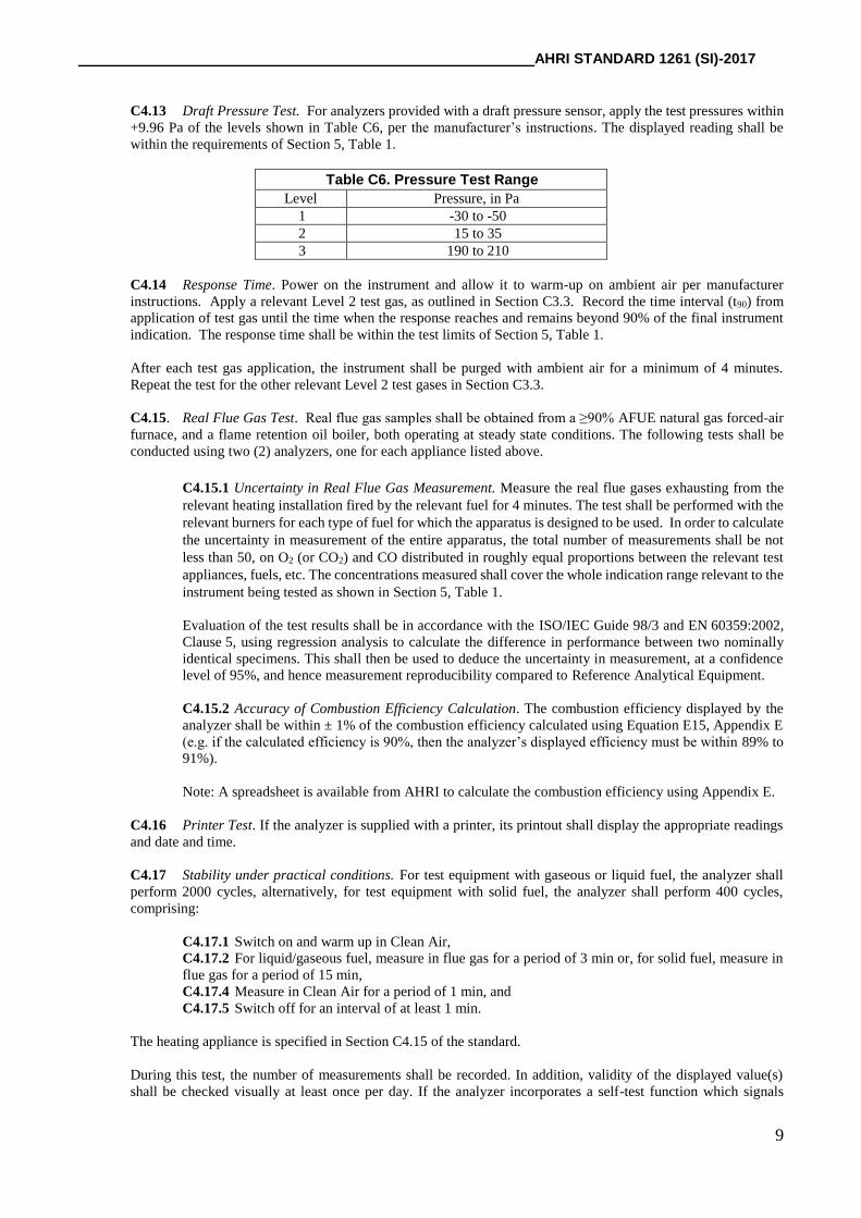
C4.13 Draft Pressure Test. For analyzers provided with a draft pressure sensor, apply the test pressures within
+9.96 Pa of the levels shown in Table C6, per the manufacturer’s instructions. The displayed reading shall be
within the requirements of Section 5, Table 1.
Table C6. Pressure Test Range
Level Pressure, in Pa
1 -30 to -50
2 15 to 35
3 190 to 210
C4.14 Response Time. Power on the instrument and allow it to warm-up on ambient air per manufacturer
instructions. Apply a relevant Level 2 test gas, as outlined in Section C3.3. Record the time interval (t90) from
application of test gas until the time when the response reaches and remains beyond 90% of the final instrument
indication. The response time shall be within the test limits of Section 5, Table 1.
After each test gas application, the instrument shall be purged with ambient air for a minimum of 4 minutes.
Repeat the test for the other relevant Level 2 test gases in Section C3.3.
C4.15. Real Flue Gas Test. Real flue gas samples shall be obtained from a ≥90% AFUE natural gas forced-air
furnace, and a flame retention oil boiler, both operating at steady state conditions. The following tests shall be
conducted using two (2) analyzers, one for each appliance listed above.
C4.15.1 Uncertainty in Real Flue Gas Measurement. Measure the real flue gases exhausting from the
relevant heating installation fired by the relevant fuel for 4 minutes. The test shall be performed with the
relevant burners for each type of fuel for which the apparatus is designed to be used. In order to calculate
the uncertainty in measurement of the entire apparatus, the total number of measurements shall be not
less than 50, on O2 (or CO2) and CO distributed in roughly equal proportions between the relevant test
appliances, fuels, etc. The concentrations measured shall cover the whole indication range relevant to the
instrument being tested as shown in Section 5, Table 1.
Evaluation of the test results shall be in accordance with the ISO/IEC Guide 98/3 and EN 60359:2002,
Clause 5, using regression analysis to calculate the difference in performance between two nominally
identical specimens. This shall then be used to deduce the uncertainty in measurement, at a confidence
level of 95%, and hence measurement reproducibility compared to Reference Analytical Equipment.
C4.15.2 Accuracy of Combustion Efficiency Calculation. The combustion efficiency displayed by the
analyzer shall be within ± 1% of the combustion efficiency calculated using Equation E15, Appendix E
(e.g. if the calculated efficiency is 90%, then the analyzer’s displayed efficiency must be within 89% to
91%).
Note: A spreadsheet is available from AHRI to calculate the combustion efficiency using Appendix E.
C4.16 Printer Test. If the analyzer is supplied with a printer, its printout shall display the appropriate readings
and date and time.
C4.17 Stability under practical conditions. For test equipment with gaseous or liquid fuel, the analyzer shall
perform 2000 cycles, alternatively, for test equipment with solid fuel, the analyzer shall perform 400 cycles,
comprising:
C4.17.1 Switch on and warm up in Clean Air,
C4.17.2 For liquid/gaseous fuel, measure in flue gas for a period of 3 min or, for solid fuel, measure in
flue gas for a period of 15 min,
C4.17.4 Measure in Clean Air for a period of 1 min, and
C4.17.5 Switch off for an interval of at least 1 min.
The heating appliance is specified in Section C4.15 of the standard.
During this test, the number of measurements shall be recorded. In addition, validity of the displayed value(s)
shall be checked visually at least once per day. If the analyzer incorporates a self-test function which signals

AHRI STANDARD 1261 (SI)-2017
10
failure during this test and automatically halts operation, it is permissible to manually reset the unit and continue
with the test. As part of this test, the manufacturer’s recommendations shall be followed regarding cleaning of
dust filters, water traps, etc. On completion of the cycles, immediately carry out all tests specified in Section C4.1.
C4.18 Sensor Replacement (if applicable). If the manufacturer allows the replacement of sensing element(s) by
the user, the sensing element(s) shall be replaced after test in Section C4.17 by new element(s) in accordance with
the instructions in the manual. After replacement, switch on the analyzer, allow the device to warm up and repeat
Section C4.1.
C5 Test Data to be recorded. All data required to determine the accuracy and resolution of the unit shall be observed
and recorded where applicable.

AHRI STANDARD 1261 (SI)-2017
11
APPENDIX D. INSTRUCTION MANUAL FOR PORTABLE FLUE GAS COMBUSTION ANALYZER - INFORMATIVE
D1 Instructions. The analyzer should have an instruction booklet, leaflet, or electronic media giving complete, clear
and accurate instructions for the safe and proper operation, handling and checking of the analyzer and include:
D1.1 Details of initial start-up delay following switch on and after battery replacement in preparation of use;
D1.2 Cross Interference. If measuring carbon monoxide (CO), the analyzer instructions should indicate if a cross
interference for nitric oxide (NO) and hydrogen (H2) is present;
D1.3 Information on correct battery type, replacement and recharging for Battery Powered units, wall voltage,
frequency and fuse rating, if relevant, and warning of possible electric shock hazards or malfunction, if
tampered with;
D1.4 Warnings against continuous use or use as a safety alarm;
D1.5 An explanation of all warning and other indications;
D1.6 A list of common materials, vapors, or gases (e.g. cleaning fluids, polishes, paints, cooking operations, etc.)
that may affect analyzer operation or reliability in the short or long term;
D1.7 Guidance on life expectancy of sensors and batteries;
D1.8 Limits of operation including temperature, humidity, and gas concentration ranges;
D1.9 Warm up time for initial switch on and after battery replacement;
D1.10 Instructions for checking, testing, and/or replacing sensing elements (where applicable), dust filter, and water
trap, and calibration and/or adjustment of the analyzer on a routine basis;
D1.11 A warning when using the analyzer that a full visual inspection of the heating appliance shall be carried out
to ensure safe operation;
D1.12 List of the type of fuels that are suitable to use with the analyzer, including those in Table E1.

AHRI STANDARD 1261 (SI)-2017
12
APPENDIX E. METHOD OF COMPUTATION FOR COMBUSTION CALCULATIONS - NORMATIVE
E1. Method of Computation for Combustion Calculations. The following standard calculations shall be used. The
calculations ignore the effect of CO in the calculation of CO2, Excess Air and dry flue loss (DFL). Flue gas relative
humidity is assumed to be 100% and inlet air relative humidity is assumed to be 50% degree of saturation.
E1.1 Oxygen. When CO2 is measured, O2 shall be calculated using Equation E1.
𝑂2 = 20.9 ∙ (1 − (𝐶𝑂2
𝐾2)) E1
Where:
𝐶𝑂2 = Carbon dioxide (measured value), %
𝑂2 = Oxygen (calculated value), %
K2 = Carbon dioxide proportion in dry flue gases at the stoichiometric point, see Table E1
E1.2 Carbon Dioxide. When O2 is measured, CO2 shall be calculated using Equation E2.
𝐶𝑂2 = 𝐾2 ∙ (1 − (𝑂2
20.9)) E2
Where:
𝐶𝑂2 = Carbon dioxide (calculated value), %
𝑂2 = Oxygen (measured value), %
Note: Once O2 and CO2 are known values (either measured or calculated), they shall be used as such in Equations E3
through E15, as required.
E1.3 Excess Air. The Excess Air is calculated using Equation E3.
𝐸𝐴 = [(20.9
20.9−𝑂2) − 1] ∙ 100 E3
Where:
𝐸𝐴 = Excess Air, %
E1.4 Carbon Monoxide (undiluted). The CO undiluted, also known as CO air-free, shall be calculated using
Equation E4.
𝐶𝑂(𝑢𝑛𝑑𝑖𝑙𝑢𝑡𝑒𝑑) = 𝐶𝑂 ∙ (20.9
20.9−𝑂2) E4
Where:
𝐶𝑂(𝑢𝑛𝑑𝑖𝑙𝑢𝑡𝑒𝑑) = Carbon monoxide referenced to 0% O2, ppm
𝐶𝑂 = Carbon monoxide (measured value), ppm
E1.5 Net Flue Gas Temperature. The net flue gas temperature shall be calculated using Equation E5.
∆𝑇 = 𝑇𝑓 − 𝑇𝑖 E5
Where:
∆𝑇 = Net flue gas temperature, °C
𝑇𝑓 = Flue gas temperature, °C

AHRI STANDARD 1261 (SI)-2017
13
𝑇𝑖 = Inlet temperature, °C
E1.6 Dry Flue Gas Loss. The dry flue gas loss shall be calculated using Equation E6.
𝐷𝐹𝐿 =𝐾1
𝐾2∙ (
20.9
20.9− 𝑂2) ∙ ∆𝑇 E6
Where:
𝐷𝐹𝐿 = Dry flue gas loss, gross basis, %
𝐾1 = Dry flue gas loss constant, gross basis, see Table E1
E1.7 Wet Flue Gas Loss. The wet flue gas loss shall be calculated using Equation E7.
𝑊𝐹𝐿 = 𝐾3 ∙ (1 + (0.001 ∙ ∆𝑇)) E7
Where:
𝑊𝐹𝐿 = Wet flue gas loss, gross basis, %
𝐾3 = Wet flue gas loss constant, gross basis, see Table E1
E1.8 Unburned Carbon Loss. The Unburned Carbon Loss shall be calculated using Equation E8.
𝑈𝐵𝐿 = 𝐾4 ∙ (𝐶𝑂
𝐶𝑂+ (𝐶𝑂2∙10000)) E8
Where:
𝑈𝐵𝐿 = Unburned carbon loss, gross basis, %
𝐾4 = Unburned carbon loss constant, gross basis, see Table E1
E1.9 Saturated Humidity Ratio as a Function of Inlet Air Temperature. The saturated humidity ratio for inlet air
shall be calculated using Equation E9.
𝐻𝑅𝑎 = 3.156 ∙ 10−3 + (1.875𝑇𝑖 ∙ 10−4) + (3.163𝑇𝑖2 ∙ 10−5) − (8.441𝑇𝑖
3 ∙ 10−7) + (1.600𝑇𝑖4 ∙ 10−8) E9
Where:
𝐻𝑅𝑎 = Saturated humidity ratio as a function of inlet air temperature
E1.10 Saturated Humidity Ratio as a Function of Flue Gas Temperature. The saturated humidity ratio for flue
gas shall be calculated using Equation E10.
𝐻𝑅𝑓𝑔 = 3.156 ∙ 10−3 + (1.875𝑇𝑓 ∙ 10−4) + (3.163𝑇𝑓2 ∙ 10−5) − (8.441𝑇𝑓
3 ∙ 10−7) + (1.600𝑇𝑓4 ∙ 10−8) E10
Where:
𝐻𝑅𝑓𝑔 = Saturated humidity ratio as a function of flue gas temperature
E1.11 Mass of Water in Air. The Mass of Water in inlet air shall be calculated using Equation E11.
𝑀𝑤𝑎 = 𝑀𝑎𝑠 ∙ (20.9
20.9− 𝑂2) ∙ 𝐻𝑅𝑎 ∙ 0.5 E11
Where:
𝑀𝑤𝑎 = Mass of water present in inlet air as a ratio of the mass of the fuel (corrected for EA)
𝑀𝑎𝑠 = Mass of inlet air at stoichiometric combustion as a ratio of the mass of the fuel, see Table E1
E1.12 Mass of Water in Flue Gas. The mass of water in flue gas shall be calculated using Equation E12.

AHRI STANDARD 1261 (SI)-2017
14
𝑀𝑤𝑓𝑔 = [𝑀𝑓𝑔𝑠 + (𝑀𝑎𝑠 ∙ ((20.9
20.9− 𝑂2) − 1))] ∙ 𝐻𝑅𝑓𝑔 E12
Where:
𝑀𝑤𝑓𝑔 = Mass of water remaining in flue gas as a ratio of the mass of fuel
𝑀𝑓𝑔𝑠 = Mass of flue gas given stoichiometric combustion as a ratio of mass of fuel, see Table E1
E1.13 Mass of Condensed Water. The Mass of condensed water shall be calculated using Equation E13.
𝑀𝑤𝑐 = 𝑀𝑤𝑓 + 𝑀𝑤𝑎 − 𝑀𝑤𝑓𝑔 E13
Where:
𝑀𝑤𝑐 = Mass of condensed water as a ratio of the mass of fuel
𝑀𝑤𝑓 = Mass of water due to hydrogen in the fuel as a ratio of mass of fuel, see Table E1
E1.14 Condensing Efficiency. The Condensing efficiency shall be calculated using Equation E14.
𝐶𝑒𝑓𝑓 = (𝑀𝑤𝑐∙(2502−2.4𝑇𝑓)
𝐻𝐻𝑉) ∙ 100 E14
Where:
𝐶𝑒𝑓𝑓= Condensing efficiency, gross basis, %
𝐻𝐻𝑉 = Higher heating value of the fuel, see Table E1, kJ/kg
E1.15 Combustion Efficiency. The combustion efficiency is a calculated value obtained from instantaneous
measurements of the combustion analyzer and is not the same as the Annual Fuel Utilization Efficiency (AFUE).
The combustion efficiency shall be calculated using Equation E15.
𝐸𝐹𝐹 = {100 − 𝐷𝐹𝐿 − 𝑊𝐹𝐿 − 𝑈𝐵𝐿 , 𝑀𝑤𝑐 < 0100 − 𝐷𝐹𝐿 − 𝑊𝐹𝐿 − 𝑈𝐵𝐿 + 𝐶𝑒𝑓𝑓 , 𝑀𝑤𝑐 ≥ 0 E15
Where:
𝐸𝐹𝐹= Combustion efficiency, %
Table E1. Fuel Constants
Fuel Constants
K1 K2 K3 K4 Mwf Mas Mfgs HHV
Natural Gas 0.346 11.8 9.78 32 2.03 15.67 14.65 50780
Propane 0.414 13.8 7.82 38 1.66 15.66 15.00 50180
Light Oil (2) 0.504 15.7 5.99 47 1.17 14.29 14.17 44178
Heavy Oil (6) 0.535 16.7 4.68 50 0.86 13.34 13.51 42161