2015 Sensitivity and Robustness Enhancements by using V-Shape Ion Funnel in FTICR-MS
5
Sensitivity and Robustness Enhancements by Using a V‑Shape Ion Funnel in FTICR-MS Liulin Deng, †,§ Xiangfeng Chen,* ,†,‡ Wan Li, † Ze Wang, † Yiling Elaine Wong, † and T.-W. Dominic Chan* ,† † Department of Chemistry, The Chinese University of Hong Kong, Hong Kong SAR, P. R. China ‡ Shandong Academy of Sciences, Jinan, Shandong, 250014, P. R. China § Biological Sciences Division and Environmental Molecular Sciences Laboratory, Pacific Northwest National Laboratory, Richland, Washington 99352, United States * S Supporting Information ABSTRACT: In this paper, a new configuration of the ion funnel interface (i.e., V-shape ion funnel (V-IF)) for high ion transmission efficiency and robustness enhancement was developed and implemented on FTICR-MS. The performance of the V-IF was compared with that of a home-built orthogonal ion funnel. An order of magnitude of improvement in sensitivity was achieved for various peptides and proteins. The performance of the instrument was maintained for a long period by neutral molecule removal. Other ion transmission patterns, such as gentle ion transmission, adduct ion removal, and radio frequency (RF)-driven collision induced dissociation (CID), was also realized in V-IF by varying the RF potentials. V- IF is believed to be a novel ion guide that has promising applications in mass spectrometry. E lectrospray ionization (ESI) 1 is one of the most important ion generation methods in mass spectrometry for large biomolecules such as peptides (or proteins) 2 and DNA 3,4 analysis. Although ESI is believed to have fairly high ionization efficiency, only a small fraction (approximately 0.01−0.1%) of analyte ions is successfully transported to the mass analyzer. 5−7 A large fraction of the ions is believed to be lost when passing through the conductance limiting orifices. In low vacuum regions, conventional electrostatic ion optical devices, such as the Einzel lens, 8−10 are ineffective in focusing the ion beam presumably because of the ion−molecule collisions and space charge effect. The situation is alleviated by using multipole ion guides (e.g., quadrupole, hexapole, and octapole). 11,12 By using radiofrequency (RF) potentials, ions can be manipulated, focused, and transmitted in medium vacuum conditions (<10 −4 mbar). The skimmer cone (SC) is normally used to transport ions from the first vacuum chamber with high pressure (10 −1 mbar to 10 mbar) to the second vacuum chamber with low pressure (10 −3 to 10 −4 mbar). Without any ion focusing properties, the SC is believed to be the sensitivity bottleneck. Gerlich demonstrated that ions can be efficiently confined and transported through a series of stacked ring electrodes with a fixed ring internal diameter by using RF electric fields with reverse polarity on adjacent electrodes. 13 The design can create a “pseudo-potential” that can achieve a steep potential gradient near every electrode and a near-field free region over most of the internal volume. A novel development of this technique was the electrodynamic ion funnel (IF) pioneered by Smith and co- workers. 14−22 This electrodynamic IF has a funnel-shaped channel formed by internal apertures of ring electrodes from the ion inlet toward the outlet end. IF was able to capture, focus, and transport ions in high efficiency by radially applying RF potentials combined with an axial direct current (DC) voltage gradient. An increase of over an order of magnitude in sensitivity for various peptides and proteins was demonstra- ted. 15,17 In ESI, highly charged droplets are generated and undergo a series of evaporation and columbic explosion to reduce the droplet mass and charge, respectively. 23 A relevant problem with the ESI source originates from the presence of solvent- related ions 24,25 and both droplet- and residue-related ion species, 26−28 which lead to an increase of contamination and chemical noise if partially transmitted into the mass spectrometer. A significant quantity of gas can also enter the vacuum system. Thus, the removal of the accompanying gas from the ions in the pathways prior to the mass analyzer is essential. 29 Many designs in ESI sources or ion guide devices, such as z-spray and step-wave (Waters, Milford, MA, U.S.A), off-axis ion funnel (Bruker Daltonics Inc., Billerica, MA), and iFunnel (Agilent Technologies, MD), have been developed and commercialized for effective removal of neutral molecules. In this study, we present a new ion guide device named the V-shaped ion funnel (V-IF), as well as an orthogonal ion funnel Received: May 5, 2015 Accepted: July 25, 2015 Published: July 28, 2015 Technical Note pubs.acs.org/ac © 2015 American Chemical Society 8073 DOI: 10.1021/acs.analchem.5b01828 Anal. Chem. 2015, 87, 8073−8077
-
Upload
liulin-deng -
Category
Documents
-
view
115 -
download
1
Transcript of 2015 Sensitivity and Robustness Enhancements by using V-Shape Ion Funnel in FTICR-MS

Sensitivity and Robustness Enhancements by Using a V‑Shape IonFunnel in FTICR-MSLiulin Deng,†,§ Xiangfeng Chen,*,†,‡ Wan Li,† Ze Wang,† Yiling Elaine Wong,†
and T.-W. Dominic Chan*,†
†Department of Chemistry, The Chinese University of Hong Kong, Hong Kong SAR, P. R. China‡Shandong Academy of Sciences, Jinan, Shandong, 250014, P. R. China§Biological Sciences Division and Environmental Molecular Sciences Laboratory, Pacific Northwest National Laboratory, Richland,Washington 99352, United States
*S Supporting Information
ABSTRACT: In this paper, a new configuration of the ionfunnel interface (i.e., V-shape ion funnel (V-IF)) for high iontransmission efficiency and robustness enhancement wasdeveloped and implemented on FTICR-MS. The performanceof the V-IF was compared with that of a home-built orthogonalion funnel. An order of magnitude of improvement insensitivity was achieved for various peptides and proteins.The performance of the instrument was maintained for a longperiod by neutral molecule removal. Other ion transmissionpatterns, such as gentle ion transmission, adduct ion removal,and radio frequency (RF)-driven collision induced dissociation (CID), was also realized in V-IF by varying the RF potentials. V-IF is believed to be a novel ion guide that has promising applications in mass spectrometry.
Electrospray ionization (ESI)1 is one of the most importantion generation methods in mass spectrometry for large
biomolecules such as peptides (or proteins)2 and DNA3,4
analysis. Although ESI is believed to have fairly high ionizationefficiency, only a small fraction (approximately 0.01−0.1%) ofanalyte ions is successfully transported to the mass analyzer.5−7
A large fraction of the ions is believed to be lost when passingthrough the conductance limiting orifices. In low vacuumregions, conventional electrostatic ion optical devices, such asthe Einzel lens,8−10 are ineffective in focusing the ion beampresumably because of the ion−molecule collisions and spacecharge effect. The situation is alleviated by using multipole ionguides (e.g., quadrupole, hexapole, and octapole).11,12 By usingradiofrequency (RF) potentials, ions can be manipulated,focused, and transmitted in medium vacuum conditions (<10−4
mbar). The skimmer cone (SC) is normally used to transportions from the first vacuum chamber with high pressure (10−1
mbar to 10 mbar) to the second vacuum chamber with lowpressure (10−3 to 10−4 mbar). Without any ion focusingproperties, the SC is believed to be the sensitivity bottleneck.Gerlich demonstrated that ions can be efficiently confined
and transported through a series of stacked ring electrodes witha fixed ring internal diameter by using RF electric fields withreverse polarity on adjacent electrodes.13 The design can createa “pseudo-potential” that can achieve a steep potential gradientnear every electrode and a near-field free region over most ofthe internal volume. A novel development of this technique wasthe electrodynamic ion funnel (IF) pioneered by Smith and co-workers.14−22 This electrodynamic IF has a funnel-shaped
channel formed by internal apertures of ring electrodes fromthe ion inlet toward the outlet end. IF was able to capture,focus, and transport ions in high efficiency by radially applyingRF potentials combined with an axial direct current (DC)voltage gradient. An increase of over an order of magnitude insensitivity for various peptides and proteins was demonstra-ted.15,17
In ESI, highly charged droplets are generated and undergo aseries of evaporation and columbic explosion to reduce thedroplet mass and charge, respectively.23 A relevant problemwith the ESI source originates from the presence of solvent-related ions24,25 and both droplet- and residue-related ionspecies,26−28 which lead to an increase of contamination andchemical noise if partially transmitted into the massspectrometer. A significant quantity of gas can also enter thevacuum system. Thus, the removal of the accompanying gasfrom the ions in the pathways prior to the mass analyzer isessential.29 Many designs in ESI sources or ion guide devices,such as z-spray and step-wave (Waters, Milford, MA, U.S.A),off-axis ion funnel (Bruker Daltonics Inc., Billerica, MA), andiFunnel (Agilent Technologies, MD), have been developed andcommercialized for effective removal of neutral molecules.In this study, we present a new ion guide device named the
V-shaped ion funnel (V-IF), as well as an orthogonal ion funnel
Received: May 5, 2015Accepted: July 25, 2015Published: July 28, 2015
Technical Note
pubs.acs.org/ac
© 2015 American Chemical Society 8073 DOI: 10.1021/acs.analchem.5b01828Anal. Chem. 2015, 87, 8073−8077

(or-IF) for comparison, to reduce the entrance gas flow andremove the neutral contaminants from the sample solvent. Theion transmission efficiency of these interfaces for varioussamples can be maintained because of the effective RFconfinement in the radial direction and the application of theappropriate DC potentials. The other ion transmissioncharacteristics of V-IF, including adduct ion retain/removaland ion dissociation, were also investigated.
■ EXPERIMENTAL SECTIONChemicals. Peptide and protein samples over a wide mass
range were used to evaluate the ion transmission properties ofor-IF and V-IF interfaces. PHE-VAL, substance P, angiotensinII, ubiquitin, cytochrome c, myoglobin, and bovine serumalbumin (BSA) were purchased from Sigma-Aldrich (St. Louis,MO, USA). All samples were used without further purification.Ion Funnel Design. Orthogonal ion funnel (or-IF) was
simply designed by perpendicularly aligning the ion funneldevice to the dielectric capillary (Figure 1A). The V-shape ion
funnel (V-IF) was designed by using a “V” shape channel totransmit ions rather than a straight channel used in thetraditional ion funnel. It had three sections: drift section, V-shape section, and funnel section, as shown in Figure 1B. Theion trajectories were simulated using SIMION 8.0. The hardsphere, elastic, ion-neutral collision model developed byAppelhans and Dahl was chosen.30 Cytochrome c ions withvarious charge states were selected to simulate the iontrajectories for the V-IF device. The details of the funnelfabrication and ion trajectory simulation process were shown inthe Supporting Information.Instrumentation. Measurements of the ion currents
transmitted through the dielectric capillary, or-IF, and V-IFwere made using an independent setup as shown in Figure S-1.All mass spectra were obtained by using an APEX47e FTICR-MS (APEX III, Bruker Instrument Inc., Boston, MA) equipped
with an unshielded 4.7 T superconducting magnet and ahomemade microspray ion source. The or-IF and V-IF wereused to replace the traditional skimmer cone interface (FigureS-2). The or-IF and V-IF were operated at the same pressure asthe traditional skimmer cone interface. The hexapole generallyworked in trapping mode which could accumulate ions for acertain period (typically 1.0 s) to increase the sensitivity ofFTICR-MS. Sample solutions were infused by a Harvardsyringe pump (South Natick, MA) at a flow rate of 10 μL/hthrough a fused-silica capillary tip (150 μm o.d., 50 μm i.d.,Polymicro Technologies, AZ, USA). The ESI tip was connectedto the grounded syringe and the entrance of the dielectriccapillary wad floated to a negative potential (∼−3000 V). Thecapillary inlet was heated by a flow of dry nitrogen gas at atemperature of 250 °C. The distance between the end of theESI tip and the heated metal capillary cap was about 1.0 mm.
■ RESULTS AND DISCUSSIONIon Trajectory Simulation. V-IF functions as a “beam
stopper” that can block gas flow by using a V-shaped channel.The neutral contaminants from the sample solvent accompany-ing the gas molecules will hit the electrodes and be pumpedaway. The transmission direction of the ion beam can bechanged at the corners of the V-shaped channel by the RFpotential. Ions can be confined and transmitted without anylosses. The trajectories of the cytochrome c ions in V-IF areshown in Figure S-3. The results show that the ions can betransmitted to the exit of V-IF with high efficiency because ofthe strong strength of the RF potential (e.g., 600 kHz, 100 Vpp).The axial DC voltage gradient (EVIF) is insensitive to the iontransmission.
Ion Transmission Efficiency. Molecular ions with sizesranging from a small molecule (PHE-VAL) to a largebiomolecule (BSA) were used to test the ion transmissionefficiency of the designed IFs. Figures S4−S6 depict the iontransmission efficiencies of or-IF and V-IF for various sampleswith the changes in RF amplitude. It can be found that the iontransmission efficiencies of V-IF can reach 60−80% and remainconstant as long as the RF amplitude is larger than 40 Vpp. Noevident ion discrimination was observed, which indicates thatV-IF can simultaneously transmit various sample ions in thesame conditions and has the potential to couple with variousmass analyzers. Effective RF potential can confine ion beams ina radial direction, which is dependent on both the RF frequencyand amplitude. The ion transmission efficiencies for varioussamples were measured by adjusting the RF amplitude atdifferent frequencies (Figure S-7). High ion transmissionefficiencies were obtained when the appropriate RF frequencyand amplitude were applied. Insufficiently strong RF potentials(e.g., 250 kHz, < 10 Vpp and 600 kHz, < 40 Vpp, etc.) cannotconfine ion beams effectively, thus leading to low iontransmission efficiencies. Extremely high RF potentials (e.g.,150 kHz, > 150 Vpp, etc.) would reduce the ion transmissionefficiencies presumably because of ion losses at the exit where ahigh RF potential exists.Collisions between the analyte ions and residual gas
molecules are advantageous for ion desolvation but candramatically reduce ion transmission efficiency. Figure S-8describes the ion transmission efficiencies for various samplesdepending on the pressure by using a fixed RF potential (600kHz, 190 Vpp). The ion transmission efficiencies for all samplesdecreased from 60−80% to 20−40% when the pressureincreased from 1.0 to 8.0 mbar. The pressure plays a key role
Figure 1. Schematics of the (A) or-IF interface and (B) V-IF interface(not in scale).
Analytical Chemistry Technical Note
DOI: 10.1021/acs.analchem.5b01828Anal. Chem. 2015, 87, 8073−8077
8074
in ion transmission. When the pressure increased, theeffectiveness of the ion confinement by the effective RFpotential is reduced, thus leading to increased ion losses. Thesituation can be improved by accordingly increasing the RFfrequency and amplitude. The ion transmission efficiencies forvarious samples were also tested by using different EVIF valueswith a specific RF potential (Figure S-9). The ion transmissionefficiencies do not significantly change as long as the DCgradient is larger than 3 V/cm, thus implying that the DCgradient is not a key parameter for ion transmission.Sensitivity Improvement. Table S-1 describes the S/N
ratio enhancements of the most abundant ion peaks in the massspectra acquired by using V-IF and or-IF for various peptideand protein samples. The mass spectra are shown in Figure S-10. The S/N ratios are enhanced by an order of magnitude forsubstance P, angiotensin II doubly charged ions, andcytochrome c multiple charged ions as compared to thetraditional SC. An enhancement of 5.2-times was obtained forPHE-VAL singly charged ions by using V-IF, which may becaused by the entrance gas dynamic effect.Robustness Enhancement. Contamination is a common
problem in ESI-MS. The transfer of excessive solvent andmatrix molecules into ion optical devices can quickly anddramatically decrease the overall sensitivity of the massspectrometers. The jet disruptor reported by Smith and co-workers31 was used in an ion funnel interface to enhance thedispersion of the directed gas flow from a multicapillary inletand reduce the pumping speed requirement. However, the gasflow can still drive the neutral contaminants to transmit into thefollowing ion optics behind the ion funnel. In our design, the V-IF was fabricated to reduce the contamination to the hexapole.As shown in Figure 2, the normalized intensities of m/z 674 ion
(1.0 μM substance P) peak in the mass spectra acquired byusing V-IF and or-IF are kept constant over 7 days. However,the normalized intensities quickly decrease by approximately45% and then remain constant over days using the original SCinterface. Therefore, V-IF can effectively eliminate neutralmolecules, thus reducing the hexapole contamination. Thedevice can extend the robustness of the entire instrumentwithout any significant change in performance over a longperiod.
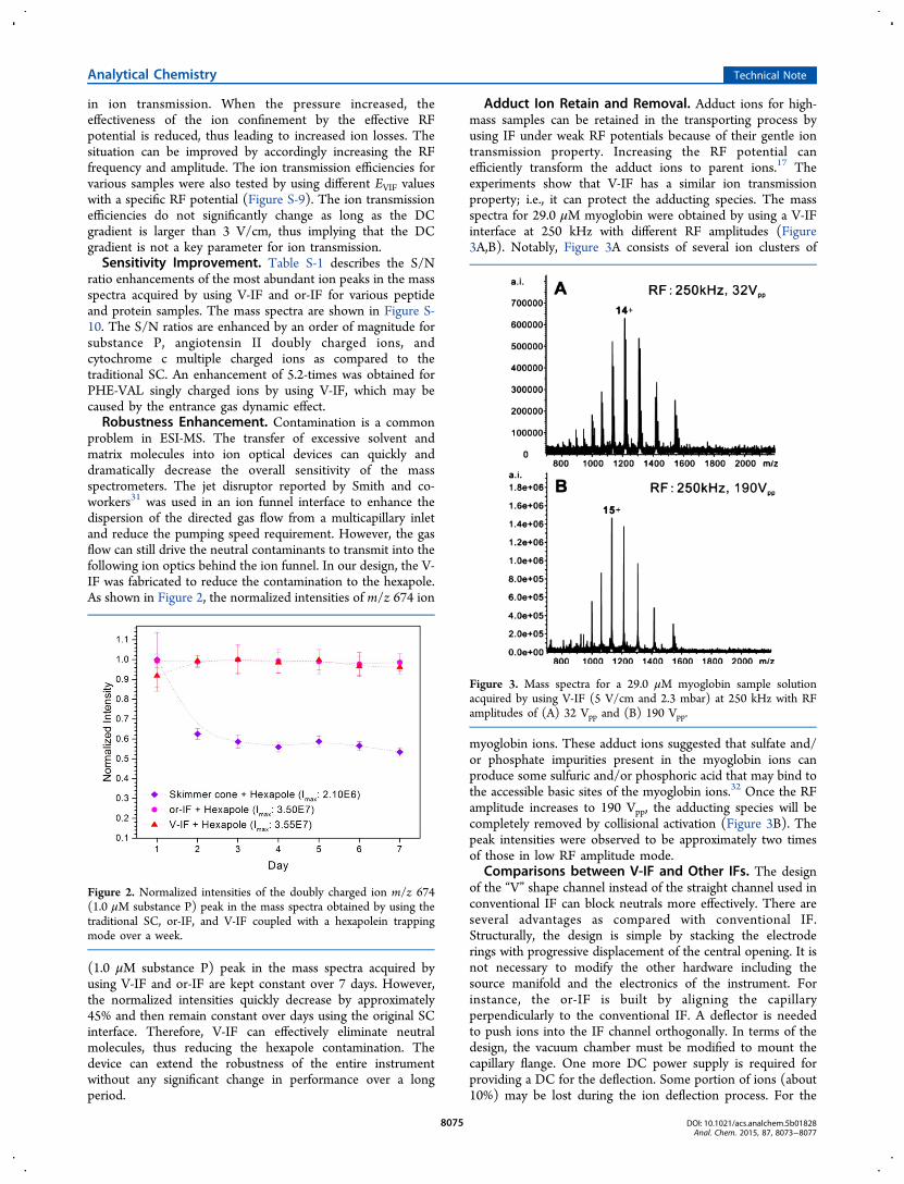
Adduct Ion Retain and Removal. Adduct ions for high-mass samples can be retained in the transporting process byusing IF under weak RF potentials because of their gentle iontransmission property. Increasing the RF potential canefficiently transform the adduct ions to parent ions.17 Theexperiments show that V-IF has a similar ion transmissionproperty; i.e., it can protect the adducting species. The massspectra for 29.0 μM myoglobin were obtained by using a V-IFinterface at 250 kHz with different RF amplitudes (Figure3A,B). Notably, Figure 3A consists of several ion clusters of
myoglobin ions. These adduct ions suggested that sulfate and/or phosphate impurities present in the myoglobin ions canproduce some sulfuric and/or phosphoric acid that may bind tothe accessible basic sites of the myoglobin ions.32 Once the RFamplitude increases to 190 Vpp, the adducting species will becompletely removed by collisional activation (Figure 3B). Thepeak intensities were observed to be approximately two timesof those in low RF amplitude mode.
Comparisons between V-IF and Other IFs. The designof the “V” shape channel instead of the straight channel used inconventional IF can block neutrals more effectively. There areseveral advantages as compared with conventional IF.Structurally, the design is simple by stacking the electroderings with progressive displacement of the central opening. It isnot necessary to modify the other hardware including thesource manifold and the electronics of the instrument. Forinstance, the or-IF is built by aligning the capillaryperpendicularly to the conventional IF. A deflector is neededto push ions into the IF channel orthogonally. In terms of thedesign, the vacuum chamber must be modified to mount thecapillary flange. One more DC power supply is required forproviding a DC for the deflection. Some portion of ions (about10%) may be lost during the ion deflection process. For the
Figure 2. Normalized intensities of the doubly charged ion m/z 674(1.0 μM substance P) peak in the mass spectra obtained by using thetraditional SC, or-IF, and V-IF coupled with a hexapolein trappingmode over a week.
Figure 3. Mass spectra for a 29.0 μM myoglobin sample solutionacquired by using V-IF (5 V/cm and 2.3 mbar) at 250 kHz with RFamplitudes of (A) 32 Vpp and (B) 190 Vpp.
Analytical Chemistry Technical Note
DOI: 10.1021/acs.analchem.5b01828Anal. Chem. 2015, 87, 8073−8077
8075
commercial off-axis IF device, it consists of a high pressure ionfunnel (HPIF) and a conventional IF. They are off axis alignedto eliminate the neutrals. However, it needs two ion funnelsetups which have a different number of electrodes and voltageparameters. The HPIF requires higher RF frequency andamplitude to achieve high ion transmission efficiencies fordifferent ions. Therefore, two sets of the RF power supplies areneeded to support the off-axis IF device. Since the HPIF andconventional IF are working in different pressure regions, onemore vacuum chamber is needed and other hardware such asthe pumping port, roughing pump, and DC power supplies arealso needed. In summary, the V-IF is simple in design and easyto operate. The performance is better than the other IFs.RF-Driven Collision Induced Dissociation. Here, we
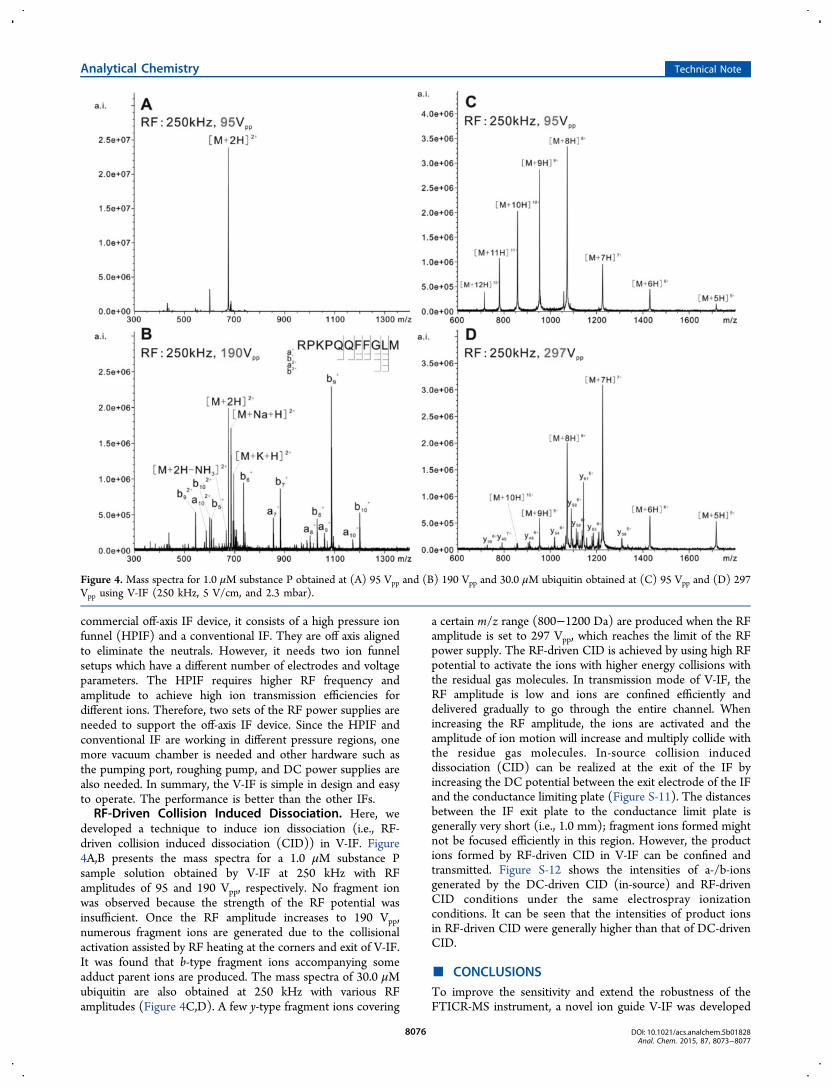
developed a technique to induce ion dissociation (i.e., RF-driven collision induced dissociation (CID)) in V-IF. Figure4A,B presents the mass spectra for a 1.0 μM substance Psample solution obtained by V-IF at 250 kHz with RFamplitudes of 95 and 190 Vpp, respectively. No fragment ionwas observed because the strength of the RF potential wasinsufficient. Once the RF amplitude increases to 190 Vpp,numerous fragment ions are generated due to the collisionalactivation assisted by RF heating at the corners and exit of V-IF.It was found that b-type fragment ions accompanying someadduct parent ions are produced. The mass spectra of 30.0 μMubiquitin are also obtained at 250 kHz with various RFamplitudes (Figure 4C,D). A few y-type fragment ions covering
a certain m/z range (800−1200 Da) are produced when the RFamplitude is set to 297 Vpp, which reaches the limit of the RFpower supply. The RF-driven CID is achieved by using high RFpotential to activate the ions with higher energy collisions withthe residual gas molecules. In transmission mode of V-IF, theRF amplitude is low and ions are confined efficiently anddelivered gradually to go through the entire channel. Whenincreasing the RF amplitude, the ions are activated and theamplitude of ion motion will increase and multiply collide withthe residue gas molecules. In-source collision induceddissociation (CID) can be realized at the exit of the IF byincreasing the DC potential between the exit electrode of the IFand the conductance limiting plate (Figure S-11). The distancesbetween the IF exit plate to the conductance limit plate isgenerally very short (i.e., 1.0 mm); fragment ions formed mightnot be focused efficiently in this region. However, the productions formed by RF-driven CID in V-IF can be confined andtransmitted. Figure S-12 shows the intensities of a-/b-ionsgenerated by the DC-driven CID (in-source) and RF-drivenCID conditions under the same electrospray ionizationconditions. It can be seen that the intensities of product ionsin RF-driven CID were generally higher than that of DC-drivenCID.
■ CONCLUSIONSTo improve the sensitivity and extend the robustness of theFTICR-MS instrument, a novel ion guide V-IF was developed
Figure 4. Mass spectra for 1.0 μM substance P obtained at (A) 95 Vpp and (B) 190 Vpp and 30.0 μM ubiquitin obtained at (C) 95 Vpp and (D) 297Vpp using V-IF (250 kHz, 5 V/cm, and 2.3 mbar).
Analytical Chemistry Technical Note
DOI: 10.1021/acs.analchem.5b01828Anal. Chem. 2015, 87, 8073−8077
8076

and evaluated by offline and online experiments. Forcomparison, a prototype or-IF was built and characterized.High ion transmission efficiencies for various peptide andprotein samples were achieved with appropriate DC and RFpotentials in a broad pressure range. An order of magnitude ofsensitivity enhancement for peptides and proteins was obtained.The neutral molecules can be effectively eliminated tosignificantly improve the robustness of the instrument usingV-IF. V-IF has the ability to preserve the noncovalent bonds byusing low RF potentials and efficiently removing the adductingspecies in a high RF amplitude mode. Furthermore, RF-drivenCID is achieved by using V-IF for various peptides and proteinsby applying high RF potentials.
■ ASSOCIATED CONTENT*S Supporting InformationThe Supporting Information is available free of charge on theACS Publications website at DOI: 10.1021/acs.anal-chem.5b01828.
Designs of V-IF and or-IF; ion trajectory simulation; ioncurrent measurements; ion transmission efficiency of or-IF; samples and ESI conditions; additional figures and atable (PDF)
■ AUTHOR INFORMATIONCorresponding Authors*E-mail: [email protected].*E-mail: [email protected] authors declare no competing financial interest.
■ ACKNOWLEDGMENTSThe authors would like to acknowledge the financial supportfrom National Natural Science Foundation of China (NSFC21205071), Research Grant Council of the Hong Kong SpecialAdministrative Region (Research Grant Direct Allocation, ref.2060351), Natural Science Foundation of Shandong Province(ZR2012BQ009), and Funds for Fostering DistinguishedYoung Scholar of Shandong Academy of Sciences. The authorsthank the staff in the mechanical and electronic workshops ofThe Chinese University of Hong Kong.
■ REFERENCES(1) Fenn, J. B.; Mann, M.; Meng, C. K.; Wong, S. F.; Whitehouse, C.M. Science 1989, 246, 64−71.(2) Beck, J. L.; Colgrave, M. L.; Ralph, S. F.; Sheil, M. M. MassSpectrom. Rev. 2001, 20, 61−87.(3) Mason, C. E.; Jergic, S.; Lo, A. T. Y.; Wang, Y.; Dixon, N. E.;Beck, J. L. J. Am. Soc. Mass Spectrom. 2013, 24, 274−285.(4) Ma, L.; Song, F. R.; Liu, Z. Q.; Liu, S. Y. Rapid Commun. MassSpectrom. 2013, 27, 51−58.(5) Cech, N. B.; Enke, C. G. Mass Spectrom. Rev. 2001, 20, 362−387.(6) Fabbi, J. C.; Rockwood, A. L.; Sin, J. C. H.; Woolley, C.; Lee, E.L.; Jones, J. Proceedings of 45th ASMS Conference on Mass Spectrometryand Allied Topics, Palm Springs, CA, 1997; p 51.(7) Zook, D. R.; Bruins, A. P. Int. J. Mass Spectrom. Ion Processes 1997,162, 129−147.(8) Busch, K. L. Spectroscopy 2009, 24, 20−25.(9) Kim, Y. C.; Kim, D. W.; Ahn, S.; Choi, S. K.; Kim, D. Y.; Kim, H.S. Jpn. J. Appl. Phys. 1 2004, 43, 3728−3730.(10) Wang, Y. L.; Shao, Z. F. Adv. Electron. El. Phys. 1991, 81, 177−209.(11) He, J.; Yu, Q.; Li, L. F.; Hang, W.; Huang, B. L. Rapid Commun.Mass Spectrom. 2008, 22, 3327−3333.
(12) Sobott, F.; Hernandez, H.; McCammon, M. G.; Tito, M. A.;Robinson, C. V. Anal. Chem. 2002, 74, 1402−1407.(13) Gerlich, D. In State Selected and State-to-State Ion−MoleculeReaction Dynamics. Part 1. Experiment; Ng, C. Y., Baer, M., Eds.; Wiley:New York, 1992; Vol. LXXXII, pp 1−176.(14) Shaffer, S. A.; Tang, K. Q.; Anderson, G. A.; Prior, D. C.;Udseth, H. R.; Smith, R. D. Rapid Commun. Mass Spectrom. 1997, 11,1813−1817.(15) Shaffer, S. A.; Prior, D. C.; Anderson, G. A.; Udseth, H. R.;Smith, R. D. Anal. Chem. 1998, 70, 4111−4119.(16) Shaffer, S. A.; Tolmachev, A.; Prior, D. C.; Anderson, G. A.;Udseth, H. R.; Smith, R. D. Anal. Chem. 1999, 71, 2957−2964.(17) Kim, T.; Tolmachev, A. V.; Harkewicz, R.; Prior, D. C.;Anderson, G.; Udseth, H. R.; Smith, R. D.; Bailey, T. H.; Rakov, S.;Futrell, J. H. Anal. Chem. 2000, 72, 2247−2255.(18) Belov, M. E.; Gorshkov, M. V.; Udseth, H. R.; Anderson, G. A.;Smith, R. D. Anal. Chem. 2000, 72, 2271−2279.(19) Belov, M. E.; Gorshkov, M. V.; Udseth, H. R.; Anderson, G. A.;Tolmachev, A. V.; Prior, D. C.; Harkewicz, R.; Smith, R. D. J. Am. Soc.Mass Spectrom. 2000, 11, 19−23.(20) Lynn, E. C.; Chung, M. C.; Han, C. C. Rapid Commun. MassSpectrom. 2000, 14, 2129−2134.(21) Kelly, R. T.; Tolmachev, A. V.; Page, J. S.; Tang, K. Q.; Smith, R.D. Mass Spectrom. Rev. 2010, 29, 294−312.(22) Giles, K.; Pringle, S. D.; Worthington, K. R.; Little, D.;Wildgoose, J. L.; Bateman, R. H. Rapid Commun. Mass Spectrom. 2004,18, 2401−2414.(23) DeJuan, L.; DelaMora, J. F. J. Colloid Interface Sci. 1997, 186,280−293.(24) Iribarne, J. V.; Thomson, B. A. J. Chem. Phys. 1976, 64, 2287−2294.(25) Thomson, B. A.; Iribarne, J. V. J. Chem. Phys. 1979, 71, 4451−4463.(26) Dole, M.; Mack, L. L.; Hines, R. L. J. Chem. Phys. 1968, 49,2240−2249.(27) Mack, L. L.; Kralik, P.; Rheude, A.; Dole, M. J. Chem. Phys.1970, 52, 4977−4986.(28) Smith, R. D.; Loo, J. A.; Loo, R. R. O.; Busman, M.; Udseth, H.R. Mass Spectrom. Rev. 1991, 10, 359−451.(29) Giles, K.; Micromass UK Limited; Ion Guide Device. U.S. PatentUS 2011/0049357 A1, 2011; pp 1−14.(30) Appelhans, A. D.; Dahl, D. A. Int. J. Mass Spectrom. 2002, 216,269−284.(31) Kim, T.; Tang, K. Q.; Udseth, H. R.; Smith, R. D. Anal. Chem.2001, 73, 4162−4170.(32) Chowdhury, S. K.; Katta, V.; Beavis, R. C.; Chait, B. T. J. Am.Soc. Mass Spectrom. 1990, 1, 382−388.
Analytical Chemistry Technical Note
DOI: 10.1021/acs.analchem.5b01828Anal. Chem. 2015, 87, 8073−8077
8077