2015 Intelligent Ground Vehicle Competition “Sparky” Intelligent Ground Vehicle Competition...
13
2015 Intelligent Ground Vehicle Competition “Sparky” I hereby cer)fy as the faculty advisor that the design and engineering of the vehicle to be entered in the 2015 Intelligent Ground Vehicle Compe))on by the current student team has been significant and equivalent to what might be awarded credit in a senior design course. Wendell Chun, Department of Electrical Engineering 1
Transcript of 2015 Intelligent Ground Vehicle Competition “Sparky” Intelligent Ground Vehicle Competition...

�
2015 Intelligent Ground Vehicle Competition “Sparky”
I hereby cer)fy as the faculty advisor that the design and engineering of the vehicle to be entered in the 2015 Intelligent Ground Vehicle Compe))on by the current student team has been significant and equivalent to what might be awarded credit in a senior design course.
Wendell Chun, Department of Electrical Engineering
�1

Table of Contents
I. Introduc)on
A. Robot
B. Team Members
C. Team Advisor
II. Robot Hierarchy
III. Mechanical Design
A. The Chassis
B. Electrical Design
C. Power
D. Schema)c
IV. SoOware Design
A. Mapping
B. Laser Data
C. Computer Vision
D. Path Planning
V. Cost
VI. Conclusion
VII. Work Cited
�2

Introduc3on The Robot: Sparky is a first genera)on robot built and designed by the current student robo)cs club members at the University of Colorado -‐Denver. The team is comprised of undergraduate and graduate Electrical Engineering students. University of Colorado at Denver has a long history of robo)cs and compe)ng in IGVC. Between 1992 and 2000, the university placed in the top four at each year’s IGVC event, including first place showings in 1998, 1999, and 2001. Since 2004 though the robo)cs team has been more scaXered rarely having a consistent team or entering any compe))ons. In 2014 a new team formed with the goal of building an obstacle avoiding robot from scratch and entering it in IGVC. Six team members from last year have remained and started a beginners robo)cs club to recruit new members. This year there is a total of nine members with three new addi)ons since last year working on the intelligent ground vehicle, Sparky. The team has also been fortunate to have the guidance and advice from a new faculty member who has spent his career in the robo)cs field, Wendell Chun. The robo)cs team has formed with the goal of learning through collabora)on and building a las)ng plaZorm that future UCD students can build on and learn from. The following report will describe how the team has gone about building the first genera)on robot through hardware, soOware, and intelligent design.
The Team Members:
Team Advisor:
�3
Name Year Role Time on Robotics
Julian Abbot-Whitley Sophmore Undergraduate Mapping Lead, path planning
One year
Nick Burton Sophmore Undergraduate Computer Vision One year
Nse Ekpoudom Senior Undergraduate Computer Vision, Laser Data, Mapping
Two years
Chris Haddad Sophmore Undergraduate Physical Design, Computer Vision
One year
Kimberly Hoskins Junior Undergraduate Mapping, Path planning
Two years
Mike Morgan Junior Undergraduate Computer Vision, GPS Lead
Two years
Ethan Steenson Senior Undergraduate Physical Design Lead Two years
Kyle Townsend Junior Undergraduate Physical Design Two years
Diane Willams Graduate Team Lead Multiple Years
Wendell Chun Lecturer in the Electrical Engineering Department
Team Advisor One year

�4
Robot Hierarchy:

Hardware Chassis: The team was granted a funding opportunity in 2014 and was able to use it to purchase a chassis off of SuperDroid robots. The model purchased was the 4WD All Terrain Heavy Duty Robot PlaZorm. The robot was built with the following hardware pieces:
The robot chassis was expanded upon in order to house the electrical components. A rod was built on top to carry the GPS and camera. A mount was added to the front for the SICK laser and another to the back that is used to strap on the computer that will run the system processes for the robot.
Electrical: Power needed to be supplied to the robot, the camera, GPS unit, encoder and IMU. The power systems currently used are:
The team is also using independent power sources. For example the computer will run en)rely on its own baXery performance. Other processes will be running on independent power supply of their own
A frizzing schema)c of the robots electrical system is provided below:
�5
Power
Mastech HIGH CURRENT SWITCHING Single-‐Output DC POWER SUPPLY 50V 20A HY5020E 1000W Amazon Mastech
Isolated DC/DC Converters 960W 24V 40A 19-‐72Vin Mouser Mean Well SD-‐1000L-‐24
Chassis, Motors
4WD All Terrain Heavy Duty Robot PlaZorm -‐ IG52 DB Op)ons: Four IG52-‐04 24VDC 285 RPM Gear Motors with Encoder, 10 inch )res, Sabertooth Dual 25A Motor Driver, Spektrum DX5eTransmiXer with AR600 Receiver SuperDroid Robo)cs TP-‐170-‐052
ATR Upper Deck and Sensor Mount SuperDroid Robo)cs TD-‐130-‐000

Safety: The robot has a 1 x 1 Channel 200M Toggle Mode Remote Switch DC 6V / 9V / 12V / 24V With Magne)c Mount Antenna. This will allow the robot to be shut down at any )me wirelessly. There is also and emergency stop buXon located on the robot that will allow the systems to be shut down if hit. The 200m receiver/transmiXer with magne)c antenna mount was purchased from RF Control systems online.
�6

SoCware: Mapping Team: The mapping teams main goal to assist the robot was to pipe in various sensory inputs from mul)ple peripheral devices that would then be used to create a map. This map would be used to plot objects and white lines on a 2D grid based off of the posi)on of the robot.
Crea3ng an Occupancy Grid: The grid that was created piped in data from the SICK Laser, Computer Vision, and GPS to create a 2D representa)on of the obstacles and white lines in reference of the posi)on of the robot. The code was wriXen mostly in python. Data coming in was organized and accessed using HDF files tools in python. This helped keep this data organized, readable, and easy to implement. The figures shown below represent how the map interprets real world data into a 2D grid:
�
�
�7
Obstacles scanned by the SICK laser
Graphical representation of those obstacles in reference to the robots location

Gathering Laser Data: The team is a SICK LMS291 S14 Laser Range Finder. The process of implemen)ng this started by wri)ng code in C to gather data from a sweep range of 45 degrees to 135 degrees. The sensor returns the measured distance informa)on. This informa)on is in two dimensional polar coordinates, (r,φ). The laser scan was completed in two dimensions. We have a known distance vector, corresponding to r, and know scan angle, corresponding to φ. The frequency of our laser is opera)ng at about 40 Hz. The laser sweeps across an obstacle field and records the data that is then sent to mapping team and ploXed on an occupancy grid. Below shows this process using graphical images.
Computer Vision: To capture the video image that will later be used to gather data by computer vision soOware the team is using a Logitech HD Pro Webcam C920. The camera is mounted on the robot and takes a short range image. Using computer visions libraries implemented in C++ the computer vision team detects white lines and red and blue flags in the robots path. This informa)on is sent to the map and ploXed in rela)on to the robot. The line and flag detec)on algorithms are very similar, due to their similar feature sets of color, edges, and dis)nct shapes. The team had to take in many varying condi)ons in order to program this successfully. The robot’s opera)ng environment is outdoors, primarily on a grass-‐covered surface. This forces us to consider how
�8
Laser distance measurement D1 Laser distance measurement D1
Map depic)ng robot posi)on and laser distance measurements
Map with detected obstacles marked in gray

different ligh)ng condi)ons will affect the color representa)on in our images. Condi)ons may vary from bright direct sunlight to cloudy, overcast days. There may also be varying degrees of shade and shadows cast by other objects. One of the robot’s opera)ng constraints is that it must operate in varying degrees of light, depending on the )me of day and weather condi)ons. Color is a quality constructed by the human visual brain system and not necessarily a property of an object. A color model is an abstract mathema)cal model describing the way colors are represented numerically. There are many color models used to display color in a digital image. The ini)al focus considered two color models: RGB (red, green, blue) and HSV (hue, satura)on, value). RGB color values vary depending on ligh)ng condi)ons, whereas the HSV color model is beXer at handling ligh)ng differences. In the RGB color space, a white line appears as we normally think of the color white. It is the brightest intensity in each of the color planes and the composite RGB image.
AOer tes)ng images taken from several different )mes of day, ligh)ng, and weather condi)ons, it was discovered that the filtering threshold values change due to different ligh)ng condi)ons. On sunny days, an image with no shadow cast on a white line generates pixels in the ranges of 240-‐255. On cloudy days, where the ligh)ng is flat, there is less contrast in an image. White pixel values will go as low as 150. Low intensity values for white pixels also occur in situa)ons when the line is in shade.
These circumstances led to the use of an adap)ve threshold. It was observed that the color white will be the brightest pixels in a gray scale image, no maXer the outdoor ligh)ng condi)ons. AOer experimenta)on with the data set, an acceptable percentage value of 5% of the highest intensity pixels in a gray scale image provided a consistent threshold for retaining white line pixels.
The total pixel count is mul)plied by the acceptable percentage value to establish a target count. The adap)ve threshold algorithm then counts down from the highest histogram bin intensity values, totaling the pixel count. When the pixel count total matches the target count, the current bin number is used as the threshold for determining white vs. non-‐white pixels.
All pixel values less than or equal to the threshold value are set to zero, and all pixels greater the threshold value are set to a maximum intensity of 255.
Dila)on was then used to fill in the gaps in the image, and erosion removed most of the noise created by the dila)on step.
All of this was used in the process of lane detec)on and obstacle avoidance for the robot.
�9

Path Planning
Using the informa)on gathered by the map the team plans to use the following weeks implemen)ng a path planning algorithm. One major problem iden)fied throughout the development process was a need to u)lize noisy sensor data for crea)ng accurate state es)ma)ons. The Kalman Filter is a recursive solu)on to the linear filtering problem, which is ideal for stochas)c es)ma)on from noisy sensor measurements. The main applica)on of the Kalman filter was to enable a system that would handle the errors associated with GPS measurements resul)ng from Ionospheric delays, atmospheric delays, Tropospheric delay, and mul)path interference. With the Kalman Filter, these errors were minimized by use of several equa)ons that func)on as a predictor-‐corrector es)mator to minimize the es)mated error covariance.
The Kalman filter uses a form of feedback control whereby an es)mate is made at some point in )me, which is then corrected using the feedback from the noisy measurement device. The equa)ons for the Kalman filter fall within two categories, )me update equa)ons and measurement update equa)ons. “The )me update equa)ons are responsible for projec)ng forward (in )me) the current state and error covariance es)mates to obtain the a priori es)mates for the next )me step. The measurement update equa)ons are responsible for the feedback—i.e. for incorpora)ng a new measurement into the a priori es)mate to obtain an improved a posteriori es)mate.” (cs.unc.edu). AOer each )me and measurement update pair, a new a posteriori es)mate is generated, using the previous es)mates, thus crea)ng a recursive system that condi)ons the current es)mate on all prior measurements. Figure n.1 contains a diagram of the filter opera)on along with the necessary predic)ve and measurement update equa)ons.
cs.unc.edu
�10

Figure n.2 contains a simulation of a GPS unit traversing an arbitrary x-‐axis with an various alterations in acceleration. While traveling a distance of 500 units, the GPS noise measurements can be seen as a cloudy haze that surrounds the actual course of travel, (shown in red), while the blue line reElects the Filtered path created by the system.
Figure n.2
Using these strategies along with other algorithms the team hopes to come up with an implementable system that allows the robot to make a decision 30 )mes a second.
�11
�12
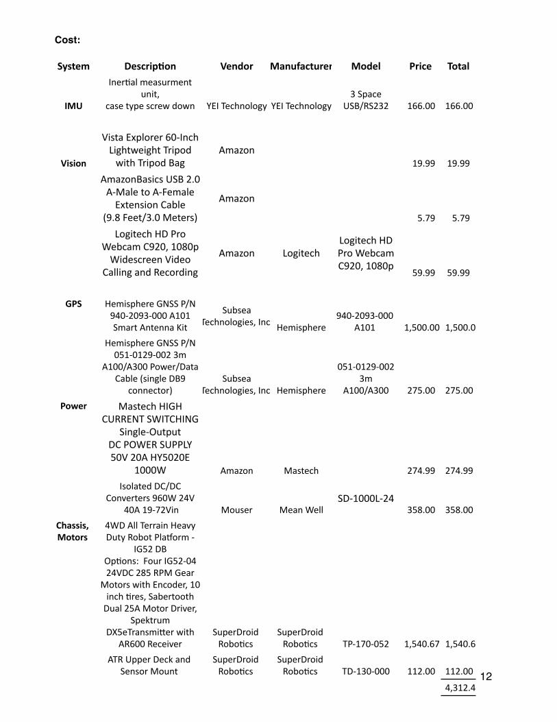
Cost:
System Descrip3on Vendor Manufacturer Model Price Total
IMU
Iner)al measurment unit,
case type screw down YEI Technology YEI Technology3 Space
USB/RS232 166.00 166.00
Vision
Vista Explorer 60-‐Inch Lightweight Tripod with Tripod Bag
Amazon 19.99 19.99
AmazonBasics USB 2.0 A-‐Male to A-‐Female Extension Cable
(9.8 Feet/3.0 Meters)
Amazon
5.79 5.79
Logitech HD Pro Webcam C920, 1080p Widescreen Video
Calling and Recording
Amazon LogitechLogitech HD Pro Webcam C920, 1080p
59.99 59.99
GPS Hemisphere GNSS P/N 940-‐2093-‐000 A101 Smart Antenna Kit
Subsea Technologies, Inc. Hemisphere
940-‐2093-‐000 A101 1,500.00 1,500.00
Hemisphere GNSS P/N 051-‐0129-‐002 3m
A100/A300 Power/Data Cable (single DB9
connector)Subsea
Technologies, Inc. Hemisphere
051-‐0129-‐002 3m
A100/A300 275.00 275.00
Power Mastech HIGH CURRENT SWITCHING
Single-‐Output DC POWER SUPPLY 50V 20A HY5020E
1000W Amazon Mastech 274.99 274.99
Isolated DC/DC Converters 960W 24V
40A 19-‐72Vin Mouser Mean WellSD-‐1000L-‐24
358.00 358.00
Chassis, Motors
4WD All Terrain Heavy Duty Robot PlaZorm -‐
IG52 DB Op)ons: Four IG52-‐04 24VDC 285 RPM Gear
Motors with Encoder, 10 inch )res, Sabertooth Dual 25A Motor Driver,
Spektrum DX5eTransmiXer with
AR600 ReceiverSuperDroid Robo)cs
SuperDroid Robo)cs TP-‐170-‐052 1,540.67 1,540.67
ATR Upper Deck and Sensor Mount
SuperDroid Robo)cs
SuperDroid Robo)cs TD-‐130-‐000 112.00 112.00
4,312.43

Conclusion: As a rookie robotics team relatively new to the subject of robotics, the team has come together with the goals of creating and understanding concepts in the robotic industry. While “Sparky” the obstacle avoiding robot still has more work needed to be fully functional, the team looks forward to continuing and completing these goal and more in the time going forward.
Acknowledgements: The team would like to thank the University of Colorado for funding and making this possible. Wendell Chun has been invaluable to the robotics club’s progress and improvement.
�13