MIC3289ww1.microchip.com/downloads/en/DeviceDoc/mic3289.pdf · 2015-11-06 · Micrel, Inc. MIC3289...
15
MIC3289 1.2MHz PWM White LED Driver with Internal Schottky Diode and True 1-Wire Digital Control MicroLead Frame and MLF are registered trademarks of Amkor Technologies. Micrel Inc. • 2180 Fortune Drive • San Jose, CA 95131 • USA • tel +1 (408) 944-0800 • fax + 1 (408) 474-1000 • http://www.micrel.com June 2007 M9999-061807 (408) 944-0800 General Description The MIC3289 is a PWM boost-switching regulator that is optimized for constant-current white LED driver applications. The MIC3289 features an internal Schottky diode, allowing an efficient DC/DC solution that requires only 4 external components. The MIC3289 allows for a single wire simple digital interface to control the dimming over 16 steps with a log scale to give better resolution at the lower currents and to better match the sensitivity of the human eye. The pre- programming feature allows the user to select any one of the 16 WLED current levels as the start-up brightness level. The feedback voltage of the MIC3289 is only 250mV, allowing high efficiency while retaining excellent accuracy for the white LED current. The MIC3289 implements a constant frequency 1.2MHz PWM control scheme. The high frequency PWM operation saves board space by reducing external component sizes. The 1.2MHz PWM scheme also reduces switching noise and ripple to the input power source. The 2.5V to 6.5V input voltage range of MIC3289 allows direct operation from single cell Li Ion as well as 3- to 4- cell NiCad/NiMH/Alkaline batteries. Battery life is preserved with a low 1μA shutdown current. The MIC3289 is available in a low profile Thin SOT23 6- lead package and a 2mm × 2mm MLF ® -8L package and has a junction temperature range of –40°C to +125°C. Data sheets and support documentation can be found on Micrel’s web site at www.micrel.com. Features • Single wire combines 16 level logarithmic brightness & shutdown control • 16V / 24V OVP options supports up to 4 & 6 WLEDs • Start-up in any one of 16 brightness levels • Internal Schottky diode • 2.5V to 6.5V input voltage • 1.2 MHz PWM operation • Over 500mA switch current • 250mV reference voltage • ±5% LED current accuracy • <1µA shutdown current • Over temperature protection • UVLO • Thin SOT23-6L package option • 2mm × 2mm leadless MLF ® -8L package option • –40 o C to +125 o C junction temperature range Applications • White/Blue LED driver for backlighting - Cell phones - PDAs - GPS systems - Digital cameras - Multimedia / MP3 players • LED flashlights • Constant current power supplies ___________________________________________________________________________________________________________
Transcript of MIC3289ww1.microchip.com/downloads/en/DeviceDoc/mic3289.pdf · 2015-11-06 · Micrel, Inc. MIC3289...

MIC3289 1.2MHz PWM White LED Driver with
Internal Schottky Diode and True 1-Wire Digital Control
MicroLead Frame and MLF are registered trademarks of Amkor Technologies. Micrel Inc. • 2180 Fortune Drive • San Jose, CA 95131 • USA • tel +1 (408) 944-0800 • fax + 1 (408) 474-1000 • http://www.micrel.com
June 2007
M9999-061807 (408) 944-0800
General Description The MIC3289 is a PWM boost-switching regulator that is optimized for constant-current white LED driver applications. The MIC3289 features an internal Schottky diode, allowing an efficient DC/DC solution that requires only 4 external components. The MIC3289 allows for a single wire simple digital interface to control the dimming over 16 steps with a log scale to give better resolution at the lower currents and to better match the sensitivity of the human eye. The pre-programming feature allows the user to select any one of the 16 WLED current levels as the start-up brightness level. The feedback voltage of the MIC3289 is only 250mV, allowing high efficiency while retaining excellent accuracy for the white LED current. The MIC3289 implements a constant frequency 1.2MHz PWM control scheme. The high frequency PWM operation saves board space by reducing external component sizes. The 1.2MHz PWM scheme also reduces switching noise and ripple to the input power source. The 2.5V to 6.5V input voltage range of MIC3289 allows direct operation from single cell Li Ion as well as 3- to 4-cell NiCad/NiMH/Alkaline batteries. Battery life is preserved with a low 1µA shutdown current. The MIC3289 is available in a low profile Thin SOT23 6-lead package and a 2mm × 2mm MLF®-8L package and has a junction temperature range of –40°C to +125°C. Data sheets and support documentation can be found on Micrel’s web site at www.micrel.com.
Features
• Single wire combines 16 level logarithmic brightness & shutdown control
• 16V / 24V OVP options supports up to 4 & 6 WLEDs • Start-up in any one of 16 brightness levels • Internal Schottky diode • 2.5V to 6.5V input voltage • 1.2 MHz PWM operation • Over 500mA switch current • 250mV reference voltage • ±5% LED current accuracy • <1µA shutdown current • Over temperature protection • UVLO • Thin SOT23-6L package option • 2mm × 2mm leadless MLF®-8L package option • –40oC to +125oC junction temperature range Applications • White/Blue LED driver for backlighting - Cell phones - PDAs - GPS systems - Digital cameras - Multimedia / MP3 players
• LED flashlights • Constant current power supplies
___________________________________________________________________________________________________________

Micrel, Inc. MIC3289
June 2007 2 M9999-061807 (408) 944-0800
Typical Application
MIC32892mm×2mm MLF
0.27µFDigital
Control
White LED Driver with OVP and Digital Control
Ordering Information
Part Number Marking Code
Output Voltage
Over Voltage Protection
Junction Temp. Range
Package
MIC3289-16YD6 WF16 Adjustable 16V -40°C to 125°C TSOT23-6
MIC3289-24YD6 WF24 Adjustable 24V -40°C to 125°C TSOT23-6
MIC3289-16YML WFA Adjustable 16V -40°C to 125°C 2x2 MLF®-8L
MIC3289-24YML WFB Adjustable 24V -40°C to 125°C 2x2 MLF®-8L
Pin Configuration
FB
GND
OUT
VIN
SW
3
1 6
2
4
5
DC
1OUT
VIN
DC
GND
8 GND
SW
FB
NC
7
6
5
2
3
4
TSOT23-6 (D) 2mm × 2mm 8-pin MLF®(ML)

Micrel, Inc. MIC3289
June 2007 3 M9999-061807 (408) 944-0800
Pin Description
Pin Number SOT23-6
Pin Number 8-pin MLF®
Pin Name Pin Name
6 1 OUT Output and Over Voltage Protection (output) 5 2 VIN Supply (Input): 2.5V to 6.5V for internal circuitry. 4 3 DC Single pin digital control. See diagrams. - 5 N/C No connect (no internal connection to die) 3 6 FB Feedback (Input): Output voltage sense node. Connect the
cathode of the LED to this pin. 1 7 SW Switch Node (Input): Internal power BIPOLAR collector. 2 4,8 GND Ground (Return): Ground. - Pad GND Ground (Return): Backside pad.

Micrel, Inc. MIC3289
June 2007 4 M9999-061807 (408) 944-0800
Absolute Maximum Ratings(1)
Supply voltage (VIN) .....................................................7.5V Switch voltage (VSW) ..................................... –0.3V to 27V Digital Control Voltage (VDC).............................. –0.3 to VIN FB Voltage (VFB) .............................................................6V Switch Current (ISW) ........................................................2A Ambient Storage Temperature (TS) .........–65°C to +150°C ESD Rating, Note 3 ..................................................... 2KV
Operating Ratings(2)
Supply Voltage (VIN) …………………..…… ..... 2.5V to 6.5V Output Voltage (VOUT) …………….…................(VIN to VOVP) Junction Temperature Range (TJ) ……......-40°C to +125°CPackage Thermal Impedance θJA 2mm × 2mm MLF®-8L ..................................93°C/W θJA TSOT23-6 ..................................................235°C/W
Electrical Characteristics(4)
TA=25oC, VIN = 3.6V, VOUT = 10V, IOUT = 20mA, unless otherwise noted. Bold values indicate -40°C ≤ TJ ≤ 125°C. Symbol Parameter Condition Min Typ Max Units
VIN Supply Voltage Range 2.5 6.5 V VUVLO Under-voltage Lockout 1.8 2.1 2.4 V IVIN Quiescent Current VFB >500mV 1.4 5 mA ISD Shutdown Current (DC pin
low ) VDC = 0V for > 2ms. 0.01 1 µA
VFB Feedback Voltage (+/-5%) 237 250 263 mV IFB Feedback Input Current VFB = 250mV 450 nA Line Regulation 2.5V ≤ VIN ≤ 4.5V 0.5 % Load Regulation 5mA ≤ IOUT ≤ 20mA 0.5 %
DMAX Maximum Duty Cycle 85 90 % ISW Switch Current Limit VIN = 3.6V 500 750 1200 mA
VDC DC pin thresholds High Low
1.1 0.4
V
DC Pin Hysteresis 20 mV IDC DC Pin Current VDC = 3.6V 5 10 µA
tshutdown Shutdown Pulse Width VIN = 2.8V to 5.5V VDC = Low
1260 µs
tMODE_UP Count UP mode pulse width VIN = 2.8V to 5.5V VDC = Low
100 160 µs
tMODE_DO
WN Count Down mode pulse width
VIN = 2.8V to 5.5V VDC = Low
420 500 µs
tstart_up Turn-on Delay Time VIN = 2.8V to 5.5V 140 µs
tprog_low Programming pulse width low
VIN = 2.8V to 5.5V 1 32 µs
tprog_high Programming pulse width high
VIN = 2.8V to 5.5V 1 32 µs
tdelay Minimum Delay for mode change
VIN = 2.8V to 5.5V VDC = High
140 µs
Tprog_setup First Pulse Window for Preprogramming
VIN = 2.8V to 5.5V 35 50 µs
fSW Oscillator Frequency 1 1.2 1.35 MHz

Micrel, Inc. MIC3289
June 2007 5 M9999-061807 (408) 944-0800
Symbol Parameter Condition Min Typ Max Units VD Schottky Forward Drop ID = 150mA 0.8 1 V IRD Schottky Leakage Current VR = 30V 4 µA
VOVP Over Voltage Protection 3289- 16 only (nominal voltage) 13 14 16 V 3289- 24 only (nominal voltage) 21 22.5 24 V
Tj Over-Temperature Threshold Shutdown
150 °C
Notes: 1. Absolute maximum ratings indicate limits beyond which damage to the component may occur. Electrical specifications do not apply when operating
the device outside of its operating ratings. The maximum allowable power dissipation is a function of the maximum junction temperature, TJ(Max), the junction-to-ambient thermal resistance, θ JA, and the ambient temperature, TA. The maximum allowable power dissipation will result in excessive die temperature, and the regulator will go into thermal shutdown.
2. This device is not guaranteed to operate beyond its specified operating rating. 3. IC devices are inherently ESD sensitive. Handling precautions required. 4. Specification for packaged product only.

Micrel, Inc. MIC3289
June 2007 6 M9999-061807 (408) 944-0800
Typical Characteristics

Micrel, Inc. MIC3289
June 2007 7 M9999-061807 (408) 944-0800
Functional Characteristics
Micrel, Inc. MIC3289
June 2007 8 M9999-061807 (408) 944-0800
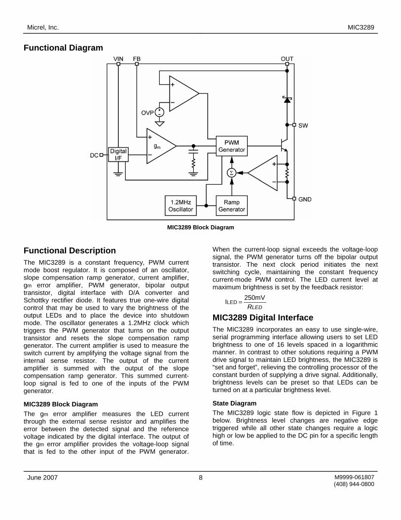
Functional Diagram
MIC3289 Block Diagram
Functional Description The MIC3289 is a constant frequency, PWM current mode boost regulator. It is composed of an oscillator, slope compensation ramp generator, current amplifier, gm error amplifier, PWM generator, bipolar output transistor, digital interface with D/A converter and Schottky rectifier diode. It features true one-wire digital control that may be used to vary the brightness of the output LEDs and to place the device into shutdown mode. The oscillator generates a 1.2MHz clock which triggers the PWM generator that turns on the output transistor and resets the slope compensation ramp generator. The current amplifier is used to measure the switch current by amplifying the voltage signal from the internal sense resistor. The output of the current amplifier is summed with the output of the slope compensation ramp generator. This summed current-loop signal is fed to one of the inputs of the PWM generator.
MIC3289 Block Diagram The gm error amplifier measures the LED current through the external sense resistor and amplifies the error between the detected signal and the reference voltage indicated by the digital interface. The output of the gm error amplifier provides the voltage-loop signal that is fed to the other input of the PWM generator.
When the current-loop signal exceeds the voltage-loop signal, the PWM generator turns off the bipolar output transistor. The next clock period initiates the next switching cycle, maintaining the constant frequency current-mode PWM control. The LED current level at maximum brightness is set by the feedback resistor:
LEDR250mV ILED =
MIC3289 Digital Interface The MIC3289 incorporates an easy to use single-wire, serial programming interface allowing users to set LED brightness to one of 16 levels spaced in a logarithmic manner. In contrast to other solutions requiring a PWM drive signal to maintain LED brightness, the MIC3289 is “set and forget”, relieving the controlling processor of the constant burden of supplying a drive signal. Additionally, brightness levels can be preset so that LEDs can be turned on at a particular brightness level.
State Diagram The MIC3289 logic state flow is depicted in Figure 1 below. Brightness level changes are negative edge triggered while all other state changes require a logic high or low be applied to the DC pin for a specific length of time.

Micrel, Inc. MIC3289
June 2007 9 M9999-061807 (408) 944-0800
Figure 1. MIC3289 Logic State Diagram
With an input supply voltage between 2.5V and 6.5V and a logic-level LOW applied to the DC pin, the MIC3289 will enter State 0, shutdown, and remain there consuming less than 1µA.
Start Up Presuming no presetting brightness command is issued (discussed in a later section), the MIC3289 will start-up in its default state approximately 140µs (tSTART_UP) after a logic level high has been applied and maintained at the DC pin. In the default state the LED drive current is at the maximum brightness level of 15 and brightness counter is set to count down mode. Any falling edges during the tPROG_SETUP period will cause the initial brightness level of the LEDs to be below the maximum brightness level. This is discussed in more detail in the Presetting Brightness section.
Figure 2. Typical Start-Up Timing
Shutdown Whenever a logic-level LOW is applied to the DC input pin for a period greater than or equal to tSHUTDOWN(1260µs), the MIC3289 will return to State 0 entering its power saving shutdown mode.
Figure 3. Shutdown Timing
Once the device is shutdown, the boost supply is disabled and the LEDs are turned off. Brightness level information stored in the MIC3289 prior to shutdown will be lost.
Programming Pulse Counter Modes Referring to the state diagram in Figure 1, notice that there are two programming pulse counting modes. At power up the MIC3289 defaults to State 1, the Count Down Mode. The counting mode can be changed to State 2, the Count Up Mode, by pulling the DC pin low for a period equal to tMODE_UP (100µs to 160µs). The device will remain in Count Up Mode until its state is changed to Count Down Mode or by disabling the MIC3289.
Figure 4. Mode Change to Count Up
Micrel, Inc. MIC3289
June 2007 10 M9999-061807 (408) 944-0800
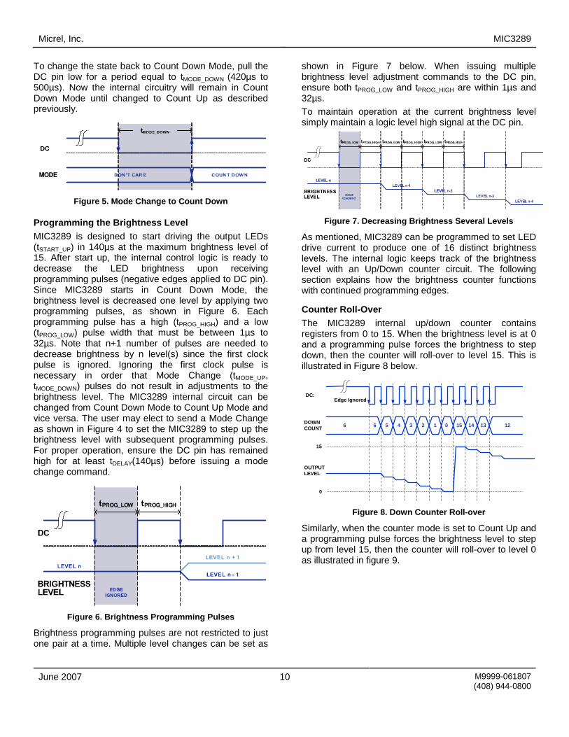
To change the state back to Count Down Mode, pull the DC pin low for a period equal to tMODE_DOWN (420µs to 500µs). Now the internal circuitry will remain in Count Down Mode until changed to Count Up as described previously.
Figure 5. Mode Change to Count Down
Programming the Brightness Level MIC3289 is designed to start driving the output LEDs (tSTART_UP) in 140µs at the maximum brightness level of 15. After start up, the internal control logic is ready to decrease the LED brightness upon receiving programming pulses (negative edges applied to DC pin). Since MIC3289 starts in Count Down Mode, the brightness level is decreased one level by applying two programming pulses, as shown in Figure 6. Each programming pulse has a high (tPROG_HIGH) and a low (tPROG_LOW) pulse width that must be between 1µs to 32µs. Note that n+1 number of pulses are needed to decrease brightness by n level(s) since the first clock pulse is ignored. Ignoring the first clock pulse is necessary in order that Mode Change (tMODE_UP, tMODE_DOWN) pulses do not result in adjustments to the brightness level. The MIC3289 internal circuit can be changed from Count Down Mode to Count Up Mode and vice versa. The user may elect to send a Mode Change as shown in Figure 4 to set the MIC3289 to step up the brightness level with subsequent programming pulses. For proper operation, ensure the DC pin has remained high for at least tDELAY(140µs) before issuing a mode change command.
Figure 6. Brightness Programming Pulses
Brightness programming pulses are not restricted to just one pair at a time. Multiple level changes can be set as
shown in Figure 7 below. When issuing multiple brightness level adjustment commands to the DC pin, ensure both tPROG_LOW and tPROG_HIGH are within 1µs and 32µs. To maintain operation at the current brightness level simply maintain a logic level high signal at the DC pin.
Figure 7. Decreasing Brightness Several Levels
As mentioned, MIC3289 can be programmed to set LED drive current to produce one of 16 distinct brightness levels. The internal logic keeps track of the brightness level with an Up/Down counter circuit. The following section explains how the brightness counter functions with continued programming edges.
Counter Roll-Over The MIC3289 internal up/down counter contains registers from 0 to 15. When the brightness level is at 0 and a programming pulse forces the brightness to step down, then the counter will roll-over to level 15. This is illustrated in Figure 8 below.
DC:
OUTPUTLEVEL
0
15
4DOWNCOUNT 3 2 1 0 15 14 13 126 6 5
Edge Ignored
Figure 8. Down Counter Roll-over
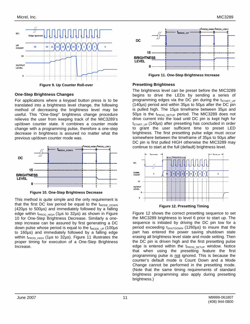
Similarly, when the counter mode is set to Count Up and a programming pulse forces the brightness level to step up from level 15, then the counter will roll-over to level 0 as illustrated in figure 9.
Micrel, Inc. MIC3289
June 2007 11 M9999-061807 (408) 944-0800
DC:
OUTPUTLEVEL
0
15
12UPCOUNT 13 14 15 0 1 2 3 410 10 11
Edge Ignored
Figure 9. Up Counter Roll-over
One-Step Brightness Changes For applications where a keypad button press is to be translated into a brightness level change, the following method of decreasing the brightness level may be useful. This “One-Step” brightness change procedure relieves the user from keeping track of the MIC3289’s up/down counter state. It combines a counter mode change with a programming pulse, therefore a one-step decrease in brightness is assured no matter what the previous up/down counter mode was.
Figure 10. One-Step Brightness Decrease
This method is quite simple and the only requirement is that the first DC low period be equal to the tMODE_DOWN (420µs to 500µs) and immediately followed by a falling edge within tPROG_HIGH (1µs to 32µs) as shown in Figure 10 for One-Step Brightness Decrease. Similarly a one-step increase can be assured by first generating a DC down pulse whose period is equal to the tMODE_UP (100µs to 160µs) and immediately followed by a falling edge within tPROG_HIGH (1µs to 32µs). Figure 11 illustrates the proper timing for execution of a One-Step Brightness Increase.
Figure 11. One-Step Brightness Increase
Presetting Brightness The brightness level can be preset before the MIC3289 begins to drive the LEDs by sending a series of programming edges via the DC pin during the tSTART_UP (140µs) period and within 35µs to 50µs after the DC pin is pulled high. The 15µs timeframe between 35µs and 50µs is the tPROG_SETUP period. The MIC3289 does not drive current into the load until DC pin is kept high for tSTART_UP (140µs) after presetting has concluded in order to grant the user sufficient time to preset LED brightness. The first presetting pulse edge must occur somewhere between the timeframe of 35µs to 50µs after DC pin is first pulled HIGH otherwise the MIC3289 may continue to start at the full (default) brightness level.
Figure 12. Presetting Timing
Figure 12 shows the correct presetting sequence to set the MIC3289 brightness to level 6 prior to start up. The sequence is initiated by driving the DC pin low for a period exceeding tSHUTDOWN (1260µs) to insure that the part has entered the power saving shutdown state erasing all brightness level state and mode setting. Then the DC pin is driven high and the first presetting pulse edge is entered within the tPROG_SETUP window. Notice that when using the presetting feature the first programming pulse is not ignored. This is because the counter’s default mode is Count Down and a Mode Change cannot be performed in the presetting mode. (Note that the same timing requirements of standard brightness programming also apply during presetting brightness.)

Micrel, Inc. MIC3289
June 2007 12 M9999-061807 (408) 944-0800
External Component Selection The MIC3289 can be used across a wide range of applications. The table below shows recommended inductor and output capacitor values for applications driving 3-6 LEDs in series assuming a 20mA maximum drive current from Li-Ion battery source.
Series LEDs L Manufacturer Min COUT Manufacturer
LQH43MN220K03 (Murata) 0603YD225MAT2A (AVX) 22µH
NLC453232T-220K (TDK) 2.2µF
GRM188R61C225KE15D (Murata)
LQH43MN100K03 (Murata) 0603YD334MAT2A (AVX) 10µH
NLCV32T-100K-PFR (TDK) 0.33µF
GRM188RT1C224KA01D (Murata)
LQH43MN4R7K03 (Murata)
3
4.7µH NLCV32T-4R7M-PFR (TDK)
0.22µF 06036ZD224MAT2A (AVX)
LQH43MN220K03 (Murata) 0805YD105MAT (AVX) 22µH
NLC453232T-220K (TDK) 1.0µF
GRM188R61E105KA12D (Murata)
LQH43MN100K03 (Murata) 06033D334MAT2A (AVX) 10µH
NLCV32T-100K-PFR (TDK) 0.33µF
GRM21BR71E334KA01L (Murata)
LQH43MN4R7K03 (Murata)
4
4.7µH NLCV32T-4R7M-PFR (TDK)
0.27µF VJ0805Y274KXAAT (Vishay)
LQH43MN220K03 (Murata) 06033D334MAT2A (AVX) 22µH
NLC453232T-220K (TDK) 0.33µF
GRM21BR71E334KA01L (Murata)
LQH43MN100K03 (Murata) 10µH
NLCV32T-100K-PFR (TDK) 0.27µF VJ0805Y274KXAAT (Vishay)
LQH43MN4R7K03 (Murata)
5,6
4.7µH NLCV32T-4R7M-PFR (TDK)
0.22µF 06036ZD224MAT2A (AVX)

Micrel, Inc. MIC3289
June 2007 13 M9999-061807 (408) 944-0800
Layout Recommendations
Top
Bottom

Micrel, Inc. MIC3289
June 2007 14 M9999-061807 (408) 944-0800
Package Information
6-Pin TSOT23 (D)
Micrel, Inc. MIC3289
June 2007 15 M9999-061807 (408) 944-0800
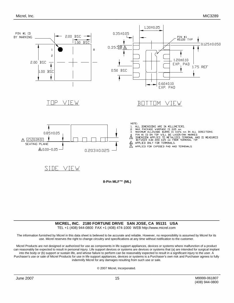
8-Pin MLF™ (ML)
MICREL, INC. 2180 FORTUNE DRIVE SAN JOSE, CA 95131 USA TEL +1 (408) 944-0800 FAX +1 (408) 474-1000 WEB http://www.micrel.com
The information furnished by Micrel in this data sheet is believed to be accurate and reliable. However, no responsibility is assumed by Micrel for its
use. Micrel reserves the right to change circuitry and specifications at any time without notification to the customer.
Micrel Products are not designed or authorized for use as components in life support appliances, devices or systems where malfunction of a product can reasonably be expected to result in personal injury. Life support devices or systems are devices or systems that (a) are intended for surgical implant
into the body or (b) support or sustain life, and whose failure to perform can be reasonably expected to result in a significant injury to the user. A Purchaser’s use or sale of Micrel Products for use in life support appliances, devices or systems is a Purchaser’s own risk and Purchaser agrees to fully
indemnify Micrel for any damages resulting from such use or sale.
© 2007 Micrel, Incorporated.