2014 Sec 4 Physics Chapter 18 Electromagnetic...
21
Chapter 18 : Electromagnetic Induction 1 2014 Sec 4 Physics Chapter 18 Electromagnetic Induction Name: ____________________ ( ) Class: 4 / ___ Levitating Barbecue! Electromagnetic Induction Source: http://www.youtube.com/watch?v=txmKr69jGBk 18 Electromagnetic Induction 18.1 Principles of electromagnetic induction 18.2 The a.c. generator 18.3 The transformer Specific Instructional Objectives (a) deduce from Faraday’s experiments on electromagnetic induction or other appropriate experiments that a changing magnetic field can induce an e.m.f. in a circuit (b) deduce from Faraday’s experiments on electromagnetic induction or other appropriate experiments that the direction of the induced e.m.f. opposes the change producing it (c) deduce from Faraday’s experiments on electromagnetic induction or other appropriate experiments the factors affecting the magnitude of the induced e.m.f. (d) describe a simple form of a.c. generator (rotating coil or rotating magnet) and the use of slip rings (where needed) (e) sketch a graph of voltage output against time for a simple a.c. generator
Transcript of 2014 Sec 4 Physics Chapter 18 Electromagnetic...
Chapter 18 : Electromagnetic Induction 1
2014 Sec 4 Physics Chapter 18
Electromagnetic Induction Name: ____________________ ( ) Class: 4 / ___
Levitating Barbecue! Electromagnetic Induction
Source: http://www.youtube.com/watch?v=txmKr69jGBk
18 Electromagnetic Induction 18.1 Principles of electromagnetic induction 18.2 The a.c. generator 18.3 The transformer
Specific Instructional Objectives
(a) deduce from Faraday’s experiments on electromagnetic induction or other appropriate experiments that a changing magnetic field can induce an e.m.f. in a circuit
(b) deduce from Faraday’s experiments on electromagnetic induction or other appropriate experiments that the direction of the induced e.m.f. opposes the change producing it
(c) deduce from Faraday’s experiments on electromagnetic induction or other appropriate experiments the factors affecting the magnitude of the induced e.m.f.
(d) describe a simple form of a.c. generator (rotating coil or rotating magnet) and the
use of slip rings (where needed) (e) sketch a graph of voltage output against time for a simple a.c. generator
Chapter 18 : Electromagnetic Induction 2
(f) describe the structure and principle of operation of a simple iron-cored
transformer as used for voltage transformations (g) recall and apply the equations VP / Vs = NP / Ns and VPIP = VsIs to new
situations or to solve related problems (for an ideal transformer) (h) describe the energy loss in cables and deduce the advantages of high voltage
transmission (i) recall and solve problems using Faraday's law of electromagnetic induction and
Lenz's law (j) explain simple applications of electromagnetic induction Read up: • Textbook: “All About Physics ‘O’ Level” Chapter 22, page 432-453. • http://hyperphysics.phy-astr.gsu.edu/hbase/electric/farlaw.html#c1 • 18.1 Principles of electromagnetic induction According to Michael Faraday, a change in the magnetic environment will cause an electromotive force (e.m.f.) to be "induced" in a conductor. The change could be produced by moving a magnet towards or away from a conducting coil, moving a conducting coil into or out of a magnetic field, rotating a coil relative to the magnet, changing the magnetic field strength etc. Faraday’s Law of Electromagnetic Induction states that the magnitude of the induced e.m.f. in a conductor is directly proportional to the rate at which magnetic field lines are cut by the conductor. Lenz’s Law states that the polarity of the induced e.m.f. is such that it produces a current whose magnetic field opposes the change which produces it.
An induced current is only present when there is a closed circuit Terms commonly used:
Chapter 18 : Electromagnetic Induction 3
Terms Comments
Electromotive force (e.m.f.)
• Measured using a voltmeter • SI unit: volt (V) • E.g. e.m.f. of a battery = 1.5 V
Induced e.m.f. An e.m.f. is “generated” in the coil. The coil behaves like a “battery”.
Induced current • When a closed circuit is connected to the coil and an induced e.m.f. is produced, an induced current flows.
• It can be detected by light bulb, a centre-zero galvanometer, voltmeter, ammeter or cathode ray oscilloscope (C.R.O.)
Factors affecting the magnitude of the induced e.m.f.
Factors To increase the induced e.m.f. (or induced current)
1 Change in speed of moving / rotating coil (or magnet)
Move / rotate coil or magnet faster
2 Strength of magnet Use a stronger magnet 3 Number of turns in coil Increase number of turns in coil 4 Soft iron in the coil Insert soft iron core in the coil
The right hand grip rule allows us to determine the direction of the induced current in a coil and hence the polarity of the induced e.m.f. Lenz’s Law is actually a law of conservation of energy. When an amount of energy is used to push the magnet into the coil, the current induced at the the coil should produce a magnetic field to repels the magnet, as this will weaken the resultant field and slows down the magnet, thus reducing the induce current. The energy from the mechanical work done against the opposing force experienced by the moving magnet is transformed into electrical energy. [Consider otherwise: if the current induced at the the coil produces a magnetic field to attract the magnet; this will strengthen the resultant field and cause the magnet to accelerate and induce a larger current, thus resulting in an ever increasing amount of energy; this is impossible!]
Chapter 18 : Electromagnetic Induction 4
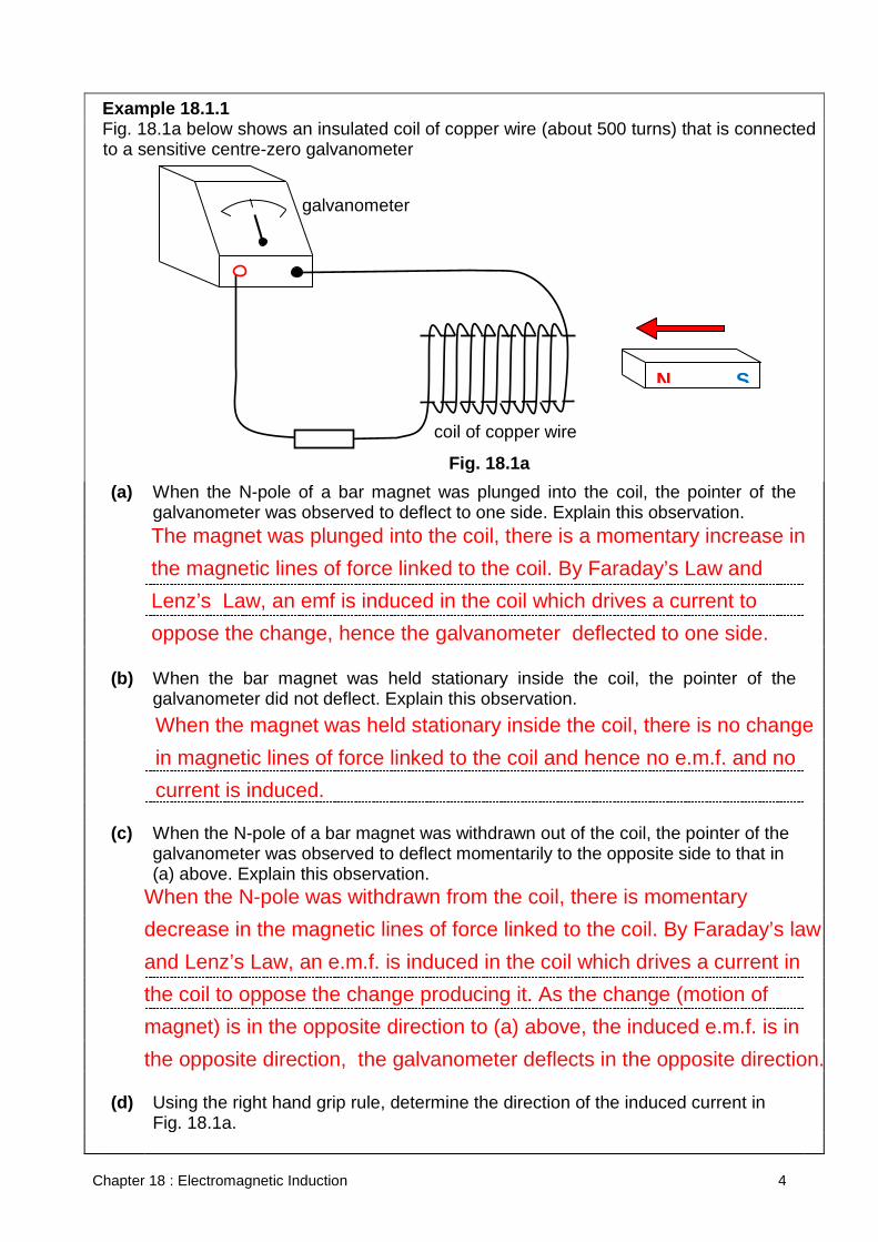
Example 18.1.1 Fig. 18.1a below shows an insulated coil of copper wire (about 500 turns) that is connected
to a sensitive centre-zero galvanometer
(a) When the N-pole of a bar magnet was plunged into the coil, the pointer of the
galvanometer was observed to deflect to one side. Explain this observation.
(b) When the bar magnet was held stationary inside the coil, the pointer of the
galvanometer did not deflect. Explain this observation.
(c) When the N-pole of a bar magnet was withdrawn out of the coil, the pointer of the
galvanometer was observed to deflect momentarily to the opposite side to that in (a) above. Explain this observation.
(d) Using the right hand grip rule, determine the direction of the induced current in
Fig. 18.1a.
galvanometer
Fig. 18.1a
N S
coil of copper wire
The magnet was plunged into the coil, there is a momentary increase in the magnetic lines of force linked to the coil. By Faraday’s Law and Lenz’s Law, an emf is induced in the coil which drives a current to oppose the change, hence the galvanometer deflected to one side.
When the magnet was held stationary inside the coil, there is no change in magnetic lines of force linked to the coil and hence no e.m.f. and no current is induced.
When the N-pole was withdrawn from the coil, there is momentary decrease in the magnetic lines of force linked to the coil. By Faraday’s law and Lenz’s Law, an e.m.f. is induced in the coil which drives a current in the coil to oppose the change producing it. As the change (motion of magnet) is in the opposite direction to (a) above, the induced e.m.f. is in the opposite direction, the galvanometer deflects in the opposite direction.
Chapter 18 : Electromagnetic Induction 5
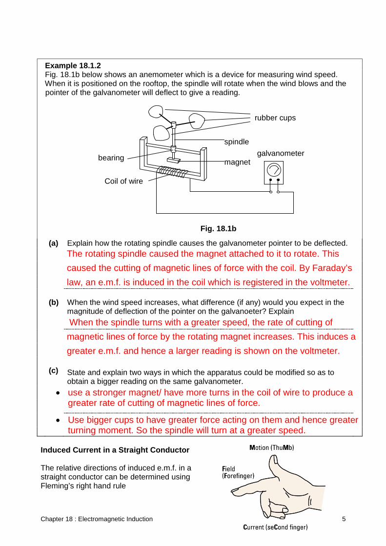
Example 18.1.2 Fig. 18.1b below shows an anemometer which is a device for measuring wind speed. When it is positioned on the rooftop, the spindle will rotate when the wind blows and the
pointer of the galvanometer will deflect to give a reading.
(a) Explain how the rotating spindle causes the galvanometer pointer to be deflected.
(b) When the wind speed increases, what difference (if any) would you expect in the
magnitude of deflection of the pointer on the galvanoeter? Explain
(c) State and explain two ways in which the apparatus could be modified so as to
obtain a bigger reading on the same galvanometer.
Induced Current in a Straight Conductor The relative directions of induced e.m.f. in a straight conductor can be determined using Fleming’s right hand rule
Fig. 18.1b
galvanometer
rubber cups
spindle
bearing magnet
Coil of wire
The rotating spindle caused the magnet attached to it to rotate. This caused the cutting of magnetic lines of force with the coil. By Faraday’s law, an e.m.f. is induced in the coil which is registered in the voltmeter.
When the spindle turns with a greater speed, the rate of cutting of magnetic lines of force by the rotating magnet increases. This induces a greater e.m.f. and hence a larger reading is shown on the voltmeter.
• use a stronger magnet/ have more turns in the coil of wire to produce a greater rate of cutting of magnetic lines of force.
• Use bigger cups to have greater force acting on them and hence greater turning moment. So the spindle will turn at a greater speed.
Chapter 18 : Electromagnetic Induction 6
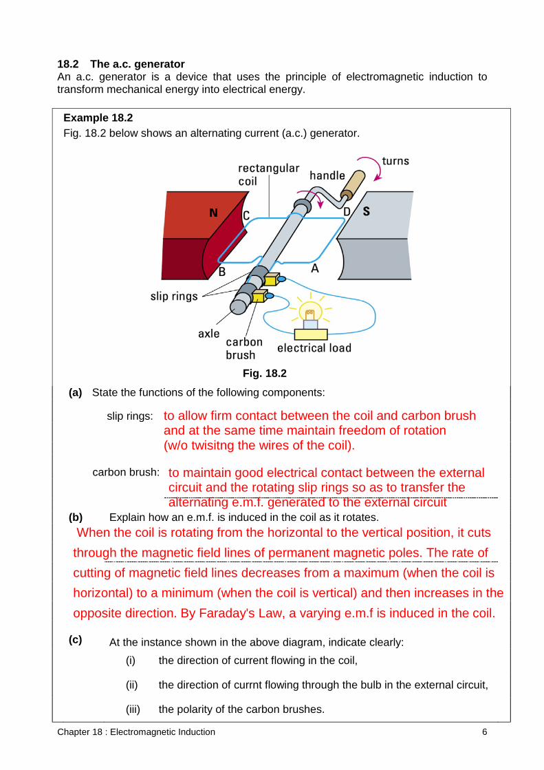
18.2 The a.c. generator An a.c. generator is a device that uses the principle of electromagnetic induction to transform mechanical energy into electrical energy. Example 18.2 Fig. 18.2 below shows an alternating current (a.c.) generator.
(a) State the functions of the following components:
slip rings:
carbon brush:
(b) Explain how an e.m.f. is induced in the coil as it rotates.
(c) At the instance shown in the above diagram, indicate clearly:
(i) the direction of current flowing in the coil,
(ii) the direction of currnt flowing through the bulb in the external circuit,
(iii) the polarity of the carbon brushes.
Fig. 18.2
to allow firm contact between the coil and carbon brush and at the same time maintain freedom of rotation (w/o twisitng the wires of the coil).
to maintain good electrical contact between the external circuit and the rotating slip rings so as to transfer the alternating e.m.f. generated to the external circuit
When the coil is rotating from the horizontal to the vertical position, it cuts through the magnetic field lines of permanent magnetic poles. The rate of cutting of magnetic field lines decreases from a maximum (when the coil is horizontal) to a minimum (when the coil is vertical) and then increases in the opposite direction. By Faraday's Law, a varying e.m.f is induced in the coil.
Chapter 18 : Electromagnetic Induction 7
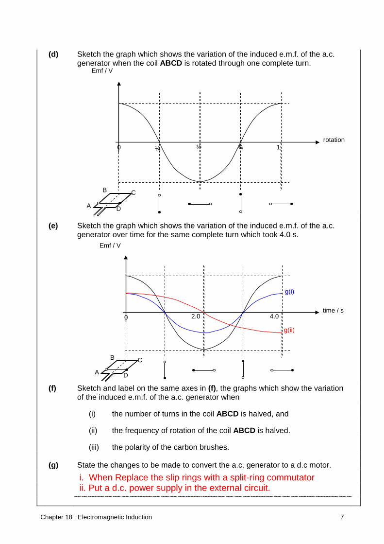
(d) Sketch the graph which shows the variation of the induced e.m.f. of the a.c.
generator when the coil ABCD is rotated through one complete turn.
(e) Sketch the graph which shows the variation of the induced e.m.f. of the a.c.
generator over time for the same complete turn which took 4.0 s.
(f) Sketch and label on the same axes in (f), the graphs which show the variation of the induced e.m.f. of the a.c. generator when
(i) the number of turns in the coil ABCD is halved, and
(ii) the frequency of rotation of the coil ABCD is halved.
(iii) the polarity of the carbon brushes.
(g) State the changes to be made to convert the a.c. generator to a d.c motor.
C B
A D
rotation ¼ 0 ½ ¾ 1
Emf / V
C B
A D
time / s 0 4.0
g(i)
Emf / V
g(ii)
2.0
i. When Replace the slip rings with a split-ring commutator ii. Put a d.c. power supply in the external circuit.
Chapter 18 : Electromagnetic Induction 8
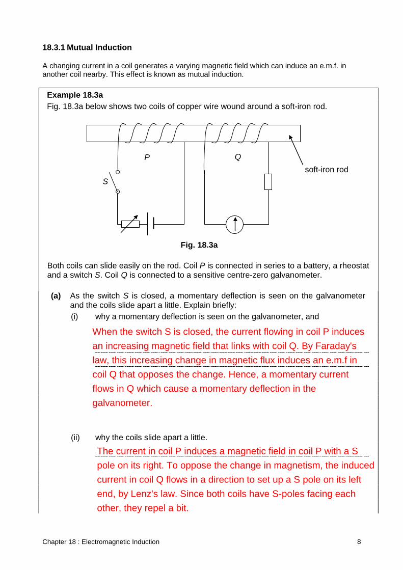
18.3.1 Mutual Induction A changing current in a coil generates a varying magnetic field which can induce an e.m.f. in another coil nearby. This effect is known as mutual induction. Example 18.3a Fig. 18.3a below shows two coils of copper wire wound around a soft-iron rod. Both coils can slide easily on the rod. Coil P is connected in series to a battery, a rheostat
and a switch S. Coil Q is connected to a sensitive centre-zero galvanometer. (a) As the switch S is closed, a momentary deflection is seen on the galvanometer
and the coils slide apart a little. Explain briefly:
(i) why a momentary deflection is seen on the galvanometer, and
(ii) why the coils slide apart a little.
Fig. 18.3a
P Q soft-iron rod
S
When the switch S is closed, the current flowing in coil P induces an increasing magnetic field that links with coil Q. By Faraday's law, this increasing change in magnetic flux induces an e.m.f in coil Q that opposes the change. Hence, a momentary current flows in Q which cause a momentary deflection in the galvanometer.
The current in coil P induces a magnetic field in coil P with a S pole on its right. To oppose the change in magnetism, the induced current in coil Q flows in a direction to set up a S pole on its left end, by Lenz's law. Since both coils have S-poles facing each other, they repel a bit.
Chapter 18 : Electromagnetic Induction 9
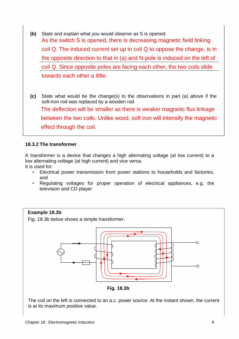
(b) State and explain what you would observe as S is opened.
(c) State what would be the change(s) to the observations in part (a) above if the
soft-iron rod was replaced by a wooden rod
18.3.2 The transformer A transformer is a device that changes a high alternating voltage (at low current) to a low alternating voltage (at high current) and vice versa. It is used for:
• Electrical power transmission from power stations to households and factories, and
• Regulating voltages for proper operation of electrical appliances, e.g. the television and CD player
Example 18.3b Fig. 18.3b below shows a simple transformer. The coil on the left is connected to an a.c. power source. At the instant shown, the current
is at its maximum positive value.
Fig. 18.3b
As the switch S is opened, there is decreasing magnetic field linking coil Q. The induced current set up in coil Q to oppose the change, is in the opposite direction to that in (a) and N-pole is induced on the left of coil Q. Since opposite poles are facing each other, the two coils slide towards each other a little. The deflection will be smaller as there is weaker magnetic flux linkage between the two coils. Unlike wood, soft iron will intensify the magnetic effect through the coil.
Chapter 18 : Electromagnetic Induction 10
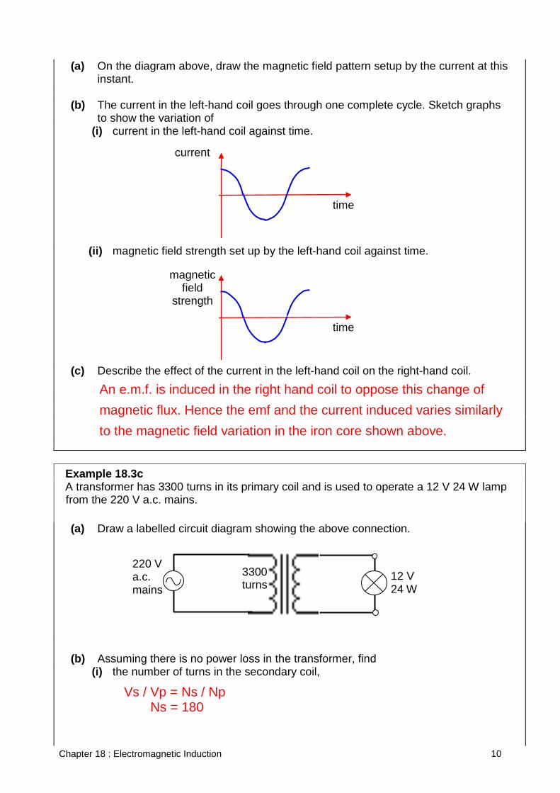
(a) On the diagram above, draw the magnetic field pattern setup by the current at this instant.
(b) The current in the left-hand coil goes through one complete cycle. Sketch graphs
to show the variation of
(i) current in the left-hand coil against time.
(ii) magnetic field strength set up by the left-hand coil against time.
(c) Describe the effect of the current in the left-hand coil on the right-hand coil.
Example 18.3c A transformer has 3300 turns in its primary coil and is used to operate a 12 V 24 W lamp
from the 220 V a.c. mains. (a) Draw a labelled circuit diagram showing the above connection.
(b) Assuming there is no power loss in the transformer, find (i) the number of turns in the secondary coil,
magnetic field
strength
time
current
time
An e.m.f. is induced in the right hand coil to oppose this change of magnetic flux. Hence the emf and the current induced varies similarly to the magnetic field variation in the iron core shown above.
220 V a.c. mains
12 V 24 W
3300 turns
Vs / Vp = Ns / Np Ns = 180
Chapter 18 : Electromagnetic Induction 11
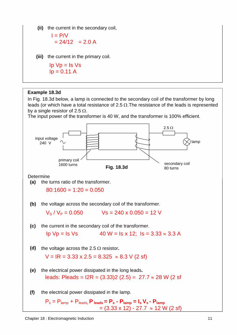
(ii) the current in the secondary coil,
(iii) the current in the primary coil.
Example 18.3d In Fig. 18.3d below, a lamp is connected to the secondary coil of the transformer by long
leads (or which have a total resistance of 2.5 Ω.The resistance of the leads is represented by a single resistor of 2.5 Ω.
The input power of the transformer is 40 W, and the transformer is 100% efficient. Determine (a) the turns ratio of the transformer.
(b) the voltage across the secondary coil of the transformer.
(c) the current in the secondary coil of the transformer.
(d) the voltage across the 2.5 Ω resistor.
(e) the electrical power dissipated in the long leads.
(f) the electrical power dissipated in the lamp.
Fig. 18.3d
lamp input voltage 240 V
secondary coil 80 turns
2.5 Ω
primary coil 1600 turns
I = P/V = 24/12 = 2.0 A
Ip Vp = Is Vs Ip = 0.11 A
80:1600 = 1:20 = 0.050
VS / VP = 0.050 Vs = 240 x 0.050 = 12 V
Ip Vp = Is Vs 40 W = Is x 12; Is = 3.33 ≈ 3.3 A
V = IR = 3.33 x 2.5 = 8.325 ≈ 8.3 V (2 sf)
leads: Pleads = I2R = (3.33)2 (2.5) = 27.7 ≈ 28 W (2 sf
Ps = Plamp + Pleads, P leads = Ps - Plamp = Is Vs - Plamp = (3.33 x 12) - 27.7 ≈ 12 W (2 sf)
Chapter 18 : Electromagnetic Induction 12
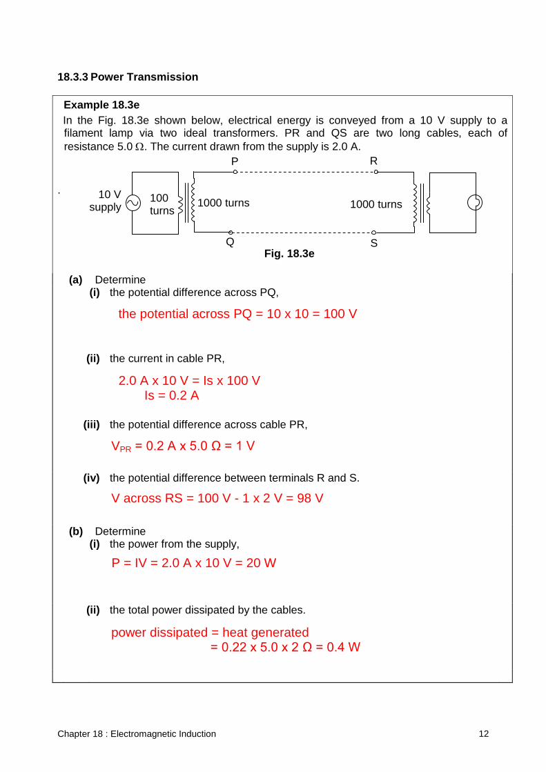
18.3.3 Power Transmission Example 18.3e In the Fig. 18.3e shown below, electrical energy is conveyed from a 10 V supply to a
filament lamp via two ideal transformers. PR and QS are two long cables, each of resistance 5.0 Ω. The current drawn from the supply is 2.0 A.
. (a) Determine (i) the potential difference across PQ,
(ii) the current in cable PR,
(iii) the potential difference across cable PR,
(iv) the potential difference between terminals R and S.
(b) Determine (i) the power from the supply,
(ii) the total power dissipated by the cables.
10 V supply
100 turns
1000 turns 1000 turns 100
turns
P R
Q S
100 turns
Fig. 18.3e
the potential across PQ = 10 x 10 = 100 V 2.0 A x 10 V = Is x 100 V Is = 0.2 A
VPR = 0.2 A x 5.0 Ω = 1 V V across RS = 100 V - 1 x 2 V = 98 V P = IV = 2.0 A x 10 V = 20 W power dissipated = heat generated = 0.22 x 5.0 x 2 Ω = 0.4 W
Chapter 18 : Electromagnetic Induction 13
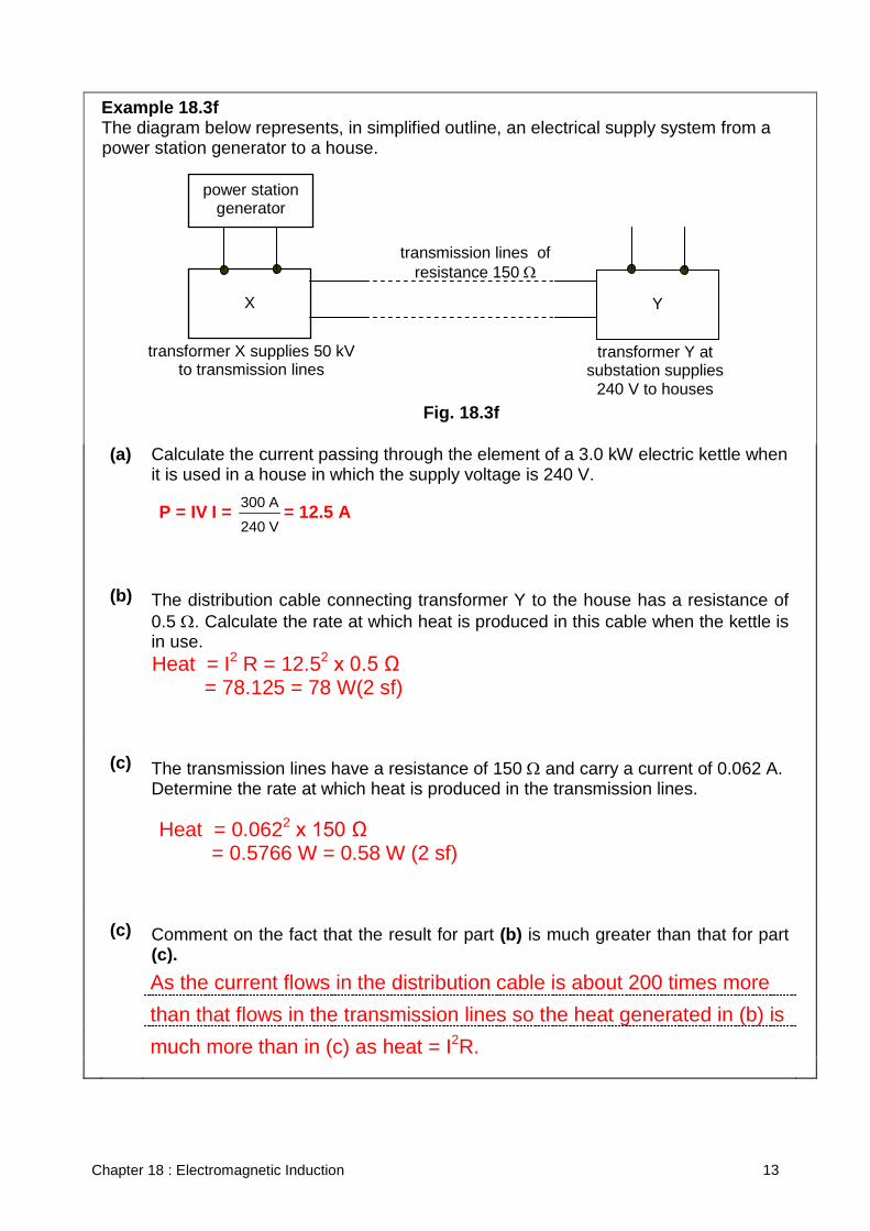
Example 18.3f The diagram below represents, in simplified outline, an electrical supply system from a
power station generator to a house. (a) Calculate the current passing through the element of a 3.0 kW electric kettle when
it is used in a house in which the supply voltage is 240 V.
(b) The distribution cable connecting transformer Y to the house has a resistance of
0.5 Ω. Calculate the rate at which heat is produced in this cable when the kettle is in use.
(c) The transmission lines have a resistance of 150 Ω and carry a current of 0.062 A.
Determine the rate at which heat is produced in the transmission lines.
(c) Comment on the fact that the result for part (b) is much greater than that for part
(c).
Fig. 18.3f
X
transformer X supplies 50 kV to transmission lines
transmission lines of resistance 150 Ω
Y
power station generator
transformer Y at substation supplies
240 V to houses
P = IV I = V240
A300 = 12.5 A
Heat = I2 R = 12.52 x 0.5 Ω = 78.125 = 78 W(2 sf)
Heat = 0.0622 x 150 Ω = 0.5766 W = 0.58 W (2 sf)
As the current flows in the distribution cable is about 200 times more than that flows in the transmission lines so the heat generated in (b) is much more than in (c) as heat = I2R.
Chapter 18 : Electromagnetic Induction 14
Example 18.3g The alternating voltage chosen for the transmission of electrical power over a large
distance is many times greater than the voltage of the domestic supply
(a) State two reasons why electrical power is transmitted at high voltage.
(b) State two advantages of using alternating voltages.
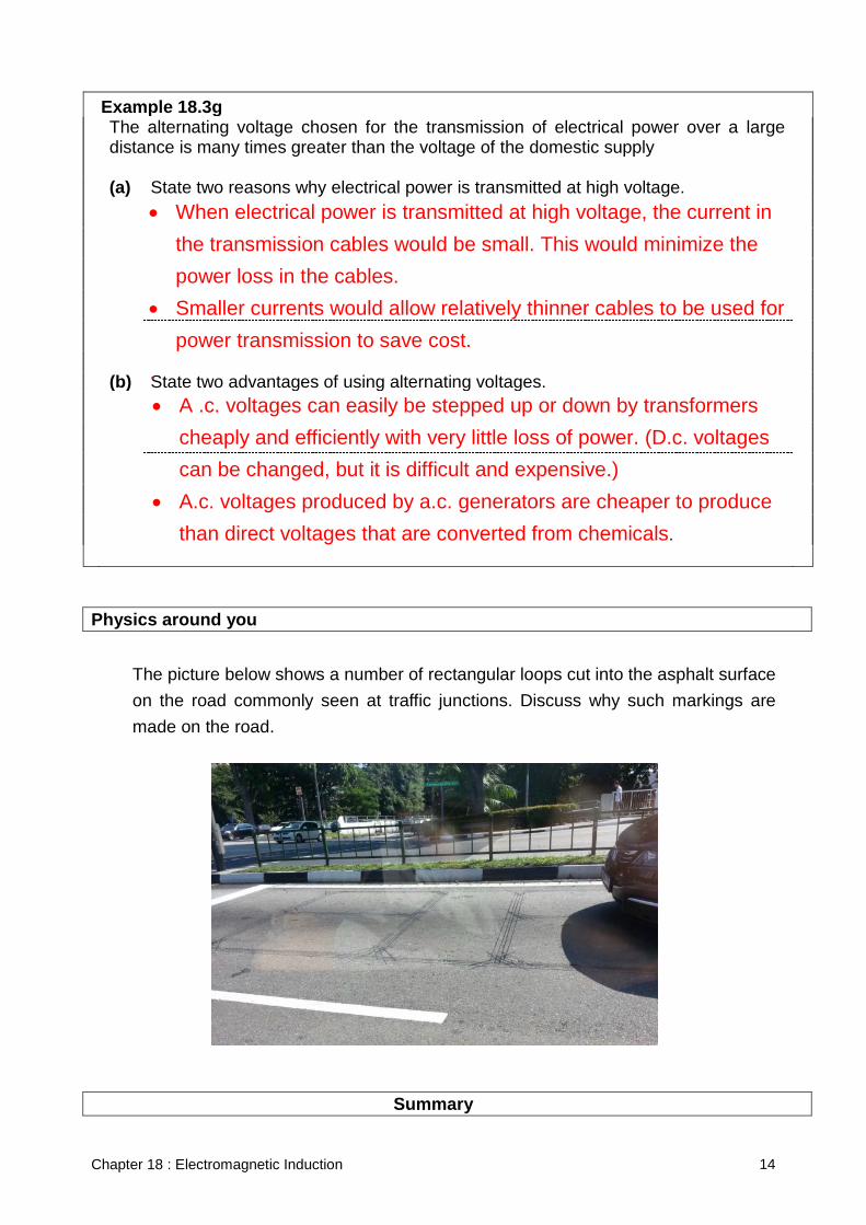
Physics around you
The picture below shows a number of rectangular loops cut into the asphalt surface on the road commonly seen at traffic junctions. Discuss why such markings are made on the road.
Summary
• When electrical power is transmitted at high voltage, the current in the transmission cables would be small. This would minimize the power loss in the cables.
• Smaller currents would allow relatively thinner cables to be used for power transmission to save cost.
.
• A .c. voltages can easily be stepped up or down by transformers cheaply and efficiently with very little loss of power. (D.c. voltages can be changed, but it is difficult and expensive.)
• A.c. voltages produced by a.c. generators are cheaper to produce than direct voltages that are converted from chemicals.
Chapter 18 : Electromagnetic Induction 15
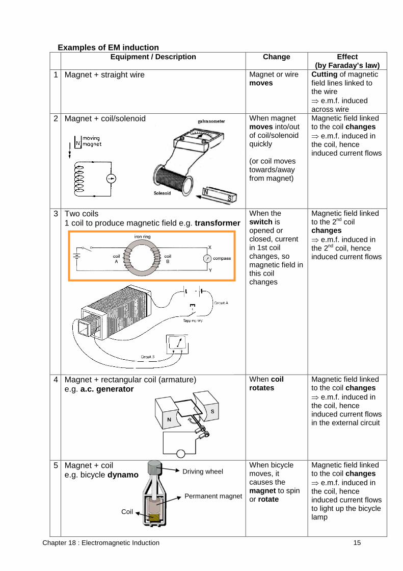
Examples of EM induction Equipment / Description Change Effect
(by Faraday’s law) 1 Magnet + straight wire Magnet or wire
moves Cutting of magnetic field lines linked to the wire ⇒ e.m.f. induced across wire
2 Magnet + coil/solenoid
When magnet moves into/out of coil/solenoid quickly (or coil moves towards/away from magnet)
Magnetic field linked to the coil changes ⇒ e.m.f. induced in the coil, hence induced current flows
3 Two coils 1 coil to produce magnetic field e.g. transformer
When the switch is opened or closed, current in 1st coil changes, so magnetic field in this coil changes
Magnetic field linked to the 2nd coil changes ⇒ e.m.f. induced in the 2nd coil, hence induced current flows
4 Magnet + rectangular coil (armature) e.g. a.c. generator
When coil rotates
Magnetic field linked to the coil changes ⇒ e.m.f. induced in the coil, hence induced current flows in the external circuit
5 Magnet + coil e.g. bicycle dynamo
When bicycle moves, it causes the magnet to spin or rotate
Magnetic field linked to the coil changes ⇒ e.m.f. induced in the coil, hence induced current flows to light up the bicycle lamp
Driving wheel
Permanent magnet
Coil
Chapter 18 : Electromagnetic Induction 16
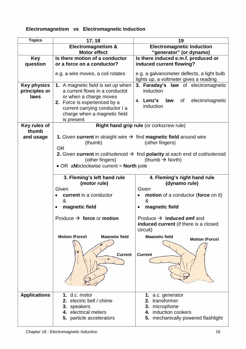
Electromagnetism vs Electromagnetic Induction
Topics 17, 18 19 Electromagnetism &
Motor effect Electromagnetic Induction “generator” (or dynamo)
Key question
Is there motion of a conductor or a force on a conductor? e.g. a wire moves, a coil rotates
Is there induced e.m.f. produced or induced current flowing? e.g. a galvanometer deflects, a light bulb lights up, a voltmeter gives a reading
Key physics principles or
laws
1. A magnetic field is set up when a current flows in a conductot or when a charge moves
2. Force is experienced by a current carrying conductor / a charge when a magnetic field is present
3. Faraday’s law of electromagnetic induction
4. Lenz’s law of electromagnetic induction
Key rules of thumb
and usage
Right hand grip rule (or corkscrew rule)
1. Given current in straight wire find magnetic field around wire (thumb) (other fingers) OR 2. Given current in coil/solenoid find polarity at each end of coil/solenoid (other fingers) (thumb North) • OR aNticlockwise current = North pole
3. Fleming’s left hand rule (motor rule)
Given • current in a conductor
& • magnetic field Produce force or motion
4. Fleming’s right hand rule (dynamo rule)
Given • motion of a conductor (force on it)
& • magnetic field Produce induced emf and induced current (if there is a closed circuit)
Applications 1. d.c. motor 2. electric bell / chime 3. speakers 4. electrical meters 5. particle accelerators
1. a.c. generator 2. transformer 3. microphone 4. induction cookers 5. mechanically powered flashlight
Motion (Force) Magnetic field
Current
Motion (Force) Magnetic field
Current
Chapter 18 : Electromagnetic Induction 17
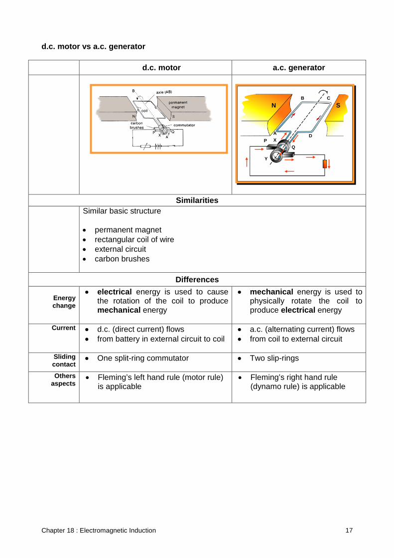
d.c. motor vs a.c. generator
d.c. motor a.c. generator
Similarities Similar basic structure
• permanent magnet • rectangular coil of wire • external circuit • carbon brushes
Differences Energy change
• electrical energy is used to cause the rotation of the coil to produce mechanical energy
• mechanical energy is used to physically rotate the coil to produce electrical energy
Current • d.c. (direct current) flows • from battery in external circuit to coil
• a.c. (alternating current) flows • from coil to external circuit
Sliding contact
• One split-ring commutator
• Two slip-rings
Others aspects
• Fleming’s left hand rule (motor rule) is applicable
• Fleming’s right hand rule (dynamo rule) is applicable
B C
D A X P
Q
N S
Y
Chapter 18 : Electromagnetic Induction 18
Exercises
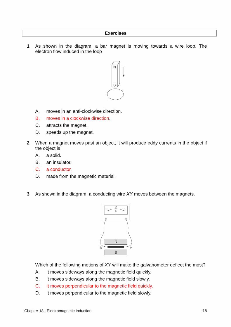
1 As shown in the diagram, a bar magnet is moving towards a wire loop. The
electron flow induced in the loop
A. moves in an anti-clockwise direction. B. moves in a clockwise direction. C. attracts the magnet. D. speeds up the magnet.
2 When a magnet moves past an object, it will produce eddy currents in the object if
the object is A. a solid. B. an insulator. C. a conductor. D. made from the magnetic material.
3 As shown in the diagram, a conducting wire XY moves between the magnets.
Which of the following motions of XY will make the galvanometer deflect the most? A. It moves sideways along the magnetic field quickly. B. It moves sideways along the magnetic field slowly. C. It moves perpendicular to the magnetic field quickly. D. It moves perpendicular to the magnetic field slowly.
Chapter 18 : Electromagnetic Induction 19
4 Rotating a wire loop between the poles of a magnet can generate electricity. Which of the following positions would induce the greatest current in the loop? A. The plane of the loop is parallel to the magnetic field. B. The plane of the loop is perpendicular to the magnetic field. C. The plane of the loop makes an angle of 45° with the magnetic field. D. The induced current is the same in all positions.
5 In a transformer, the secondary loop has twice as many turns as the primary. If the
alternating current in the primary loop is 2.0 A, what is the current in the secondary loop? A. 1.0 A B. 2.0 A C. 4.0 A D. It cannot be determined.
6 Which of the following statements about generators and motors are correct?
A. The working principle of motors is based on electromagnetic induction. B. Motors convert electrical energy to mechanical energy. C. The working principle of generators is based on the magnetic effect of a
current. D. Generators convert electrical energy to mechanical energy.
7 The voltage across the input terminals of a transformer is 110 V. The primary has
50 loops and the secondary has 120 loops. The output voltage of the transformer is A. 46 V. B. 55 V. C. 180 V. D. 264 V.
8 In which of the following situations is a voltage induced in a conductor?
A. The conductor moves through the air. B. The conductor is connected to a battery. C. The conductor is connected to a motor. D. The conductor is moved in a magnetic field.
Chapter 18 : Electromagnetic Induction 20
9 Faraday’s law of electromagnetic induction describes how an electric field can be reduced at a point in space by A. an electric charge. B. a constant magnetic field. C. a changing magnetic field. D. a steady current.
10 Which of the following statements about d.c. and a.c generators is / are correct?
(1) An a.c. generator can be converted to a d.c. generator by replacing the commutator with two slip rings.
(2) Both of them convert mechanical energy to electrical energy. (3) The methods to increase the induced voltage in these two types of generators
are in totally opposite ways. A. (1) only B. (2) only C. (1) and (2) only D. (2) and (3) only
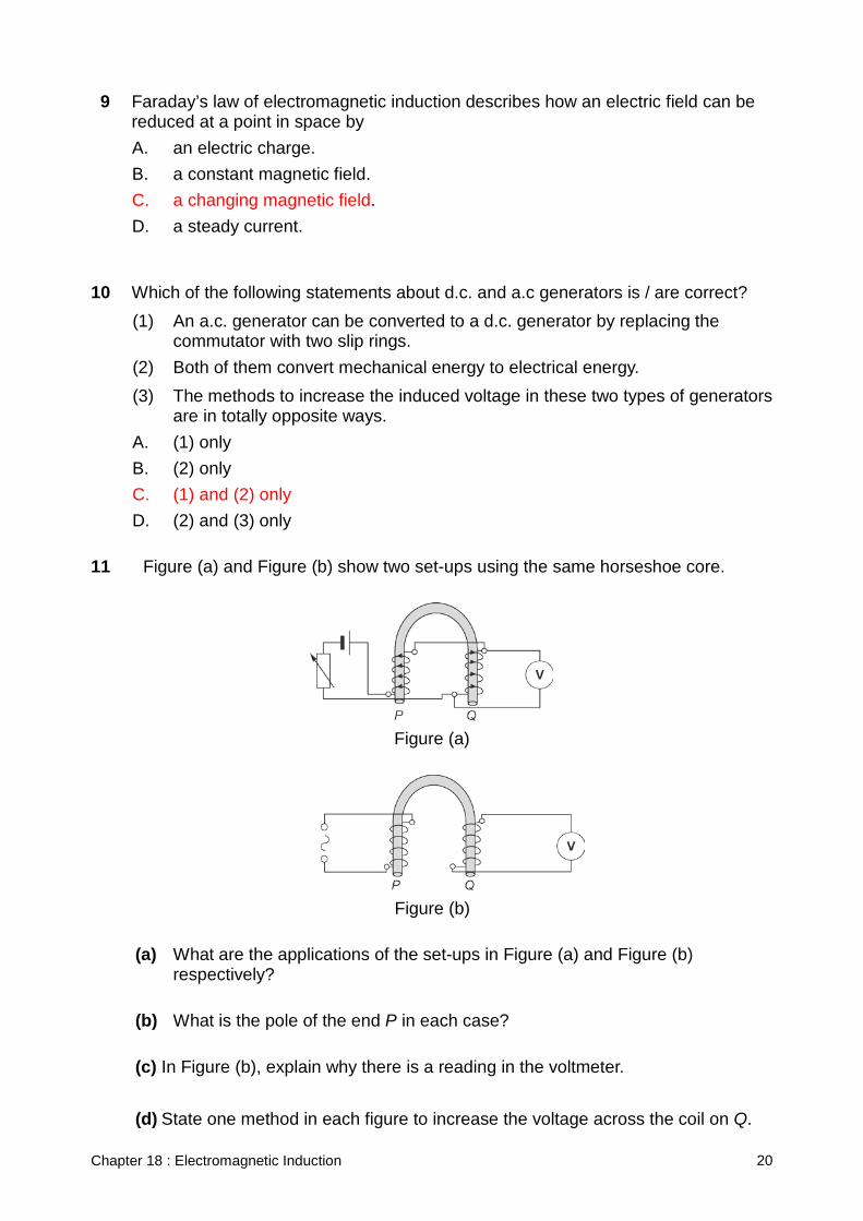
11 Figure (a) and Figure (b) show two set-ups using the same horseshoe core.
Figure (a)
Figure (b)
(a) What are the applications of the set-ups in Figure (a) and Figure (b)
respectively? (b) What is the pole of the end P in each case? (c) In Figure (b), explain why there is a reading in the voltmeter.
(d) State one method in each figure to increase the voltage across the coil on Q.
Chapter 18 : Electromagnetic Induction 21
11 (a) In Figure (a), it is an electromagnet. In Figure (b), it is a transformer. (b) In Figure (a), P is the north pole. It is decided by the right
hand grip rule. In Figure (b), P is alternately north pole and south pole as the current flowing through it is a.c.
(c) As P is connected to the a.c., the alternating current causes a
changing magnetic field which is linked to Q through the horseshoe core. By electromagnetic induction, there is a current induced in the coil wound on Q and thus a voltage induced across the coil.
(d) For the set-up in Figure (a), the rheostat is adjusted so that
more current can flow through the coil. For the set-up in Figure (b), increase the number of turns of coil on Q or decrease the number of turns of coil on P.