2014 PIPELINE MAINTENANCE AND REPAIR EAGLE MINE …...2014 Pipeline Maintenance and Repair April 15,...
28
2014 PIPELINE MAINTENANCE AND REPAIR EAGLE MINE SITE MINTURN, COLORADO Prepared for: CBS Operations Inc. April 15, 2015 730 17 th Street, Suite 925 Denver, Colorado 80202
Transcript of 2014 PIPELINE MAINTENANCE AND REPAIR EAGLE MINE …...2014 Pipeline Maintenance and Repair April 15,...

2014 PIPELINE MAINTENANCE AND REPAIR EAGLE MINE SITE MINTURN, COLORADO Prepared for: CBS Operations Inc. April 15, 2015
730 17th Street, Suite 925 Denver, Colorado 80202

2014 Pipeline Maintenance and Repair April 15, 2015
TABLE OF CONTENTS
1 TIP TOP MINE AND ADIT 143 ............................................................................ 2
2 TIP TOP MINE TO BELDEN ............................................................................... 5
3 BELDEN TO ROCK CREEK ............................................................................... 5
4 ROCK CREEK PIPELINES ................................................................................. 7 4.1 MDD ......................................................................................................... 7 4.2 Mine Water Return System (aka Pumpback) ............................................ 8 4.3 Seep Collection Line ................................................................................ 8
5 ROCK CREEK TO MANHOLE 0 (MH-0) ........................................................... 10
6 MH-0 TO 8-INCH DIAMETER BYPASS LINE ................................................... 11
7 WOODEN TRESTLE ......................................................................................... 13
8 8-INCH DIAMETER BYPASS TO OTP MANHOLE ........................................... 14
9 OTP MANHOLE TO WTP ................................................................................. 16
10 CTP PIPELINES ................................................................................................ 19
11 BIBLIOGRAPHY ............................................................................................... 20
LIST OF FIGURES Figure 1 Tip Top mine portal ........................................................................................ 3 Figure 2 Tip Top and Belden Pipeline Layout............................................................... 3 Figure 3 Tip Top manhole in crib wall .......................................................................... 4 Figure 4 Crib wall and location of buried 12-inch diameter HDPE pipeline downstream
of Tip Top manhole ........................................................................................ 5 Figure 5 Lowermost portion of 6-inch diameter MDD pipeline ...................................... 7 Figure 6 Adit 5 Portal Door........................................................................................... 9 Figure 7 2-inch diameter pipe exiting lower intermediate manhole in Rock Creek ........ 9 Figure 8 MH-0 looking upstream to Gate #2 .............................................................. 11 Figure 9 Junction of 8-in diameter bypass and 12-in diameter wooden trestle,
upper Rex Flats ........................................................................................... 12 Figure 10 Wooden trestle crossing Rex Flats and typical T port on the 12-in diameter
HDPE pipe inside the wood stave pipe. ....................................................... 13 Figure 11 Trestle in Rex Flats ...................................................................................... 14
i \\DHINRICHS-990\Projects\CBS Eagle\Pipeline\2014 Inspection\2014 Pipeline Inspection report.docx

2014 Pipeline Maintenance and Repair April 15, 2015
LIST OF FIGURES (CONT.) Figure 12 Rock Box (left) and auxiliary cleanout being installed on bypass .................. 15 Figure 13 OTP manhole, downstream is to the right .................................................... 16 Figure 14 Garage Manhole looking downstream to location of WTP ............................ 17 Figure 15 Trestle crossing Rex Flats (left) to WTP segment (right). Tigwon Road
crosses the photograph from right to left. ..................................................... 18
LIST OF APPENDICES
A Pipeline drawings and schematics
ii \\DHINRICHS-990\Projects\CBS Eagle\Pipeline\2014 Inspection\2014 Pipeline Inspection report.docx

2014 Pipeline Maintenance and Repair April 15, 2015
2014 PIPELINE MAINTENANCE AND REPAIR
EAGLE MINE SITE, MINTURN, COLORADO
This report summarizes the maintenance and repair work completed on the Eagle mine pipelines and associated structures in 2014 and the planned maintenance and upgrade tasks for 2015. Two systems carry water to the treatment plant or WTP. The main pipeline conveys mine water down the Eagle River canyon and a separate pipeline collects groundwater from two French drains at the Consolidated Tailings Pile (CTP).
Historically, the main pipeline carried tailings from Empire Zinc Company’s 650–ton per day underground mill at Belden to a 20-acre pond at Rex Flats that is now called the Old Tailings Pile or OTP. The buried line was constructed of an 18-inch diameter reinforced concrete bell-and-spigot pipe (RCP) along the railroad at a grade of 2 to 4 percent. The old tailings line crossed the river at what is now termed the South Rex junction box in 220 feet of 18 -inch diameter suspended spiral steel pipe, thence 1420 feet of wood stave pipe on the ground to the OTP tailings dam. In total the line was 8,820 feet long. The tailings disposal system and mill were in operation by 1929 (Borcherdt, 1937). In the 1940s, The New Jersey Zinc Company Inc. extended the tailings line from the upper end of the 1929 river crossing, across Rex Flats and the river, to a new tailings pond in an 18-in diameter wood stave pipe supported in large part by above-ground wood trestles. This new tailings pond is now called the CTP.
For the Superfund remedy, the buried RCP and wood stave pipe were lined with 6-in, 10-in, and 12-in diameter high density polyethylene (HDPE) pipe. An extension of 6-in diameter HDPE pipe was buried from Belden upstream to collect water from the Tip Top mine. Where the line is buried in RCP, the old concrete manholes were demolished and replaced with HDPE saddle-type T inspection ports electro-fused to the main line. These T ports have bolt-on metal or plastic lids and rubber gaskets to prevent the entry of air. Similar T ports were placed along the elevated section by cutting holes in the wood stave pipe on 300 foot intervals.
Jetting of the lines to remove iron scale is accomplished using treated water from the WTP or river water obtained from the water right decree site at Belden. During jetting, the scale cuttings (also called iron chips or product) are loosened with a cutter head and spray (typically 2800 to 3200 psi). The scale, injected water and water in the pipeline are extracted with a vacuum truck at a T fitting immediately downstream of the work site. When the truck is full, 2500 to 3200 gallons, the water and scale are dumped at the Sludge Cell at the WTP. Included in Appendix A are diagrams of the pipelines with manholes and cleanouts identified.
1 \\DHINRICHS-990\Projects\CBS Eagle\Pipeline\2014 Inspection\2014 Pipeline Inspection report.docx

2014 Pipeline Maintenance and Repair April 15, 2015
1 TIP TOP MINE AND ADIT 143
The Tip Top mine (Figure 1) is the most upstream seepage collection point on the main pipeline. Two pipes drain the Tip Top mine portal at elevation 8411 feet. One 3-inch diameter line drains groundwater that seeps from the rock around the Tip Top bulkhead (seep line) into the tunnel. This bulkhead is located 300 feet inboard from the portal. Another 3-inch diameter line drains the water that collects in the mine behind the mine bulkhead (pressure line). The two lines exit the portal area separately but join at a wye connection about 20 feet outside the portal. The joined flows are conveyed in a 3-inch diameter HDPE line to the Tip Top manhole located along the Crib Wall next to the railroad.
If the Tip Top mine fills with 35 feet of water, the mine pool behind the bulkhead will drain out of a secondary tunnel, Adit 143, at elevation 8446 feet. Originally, a 2-inch diameter drain line extended from Adit 143 to the Tip Top manhole (Figure 2). Over the years, rock slides and avalanches have destroyed the 2-inch diameter line and filled the tunnel with rock. Overflow is difficult to detect due to the rock talus on the steep slope that has buried Adit 143.
Tip Top flow on the pressure line is controlled by a gate valve inside the portal. With the valve in the fully open position, flows of 10 to 30 gpm can be generated depending on the height of the mine pool. A pressure gauge is present and the mine pool level can be estimated by reading the shut-in (gate valve closed) pressure. A pressure of less than 1 psi indicates that the Tip Top mine is drained down to its base level of near 8411 feet. By April 2014, the line pressure had reached 6 psi and by June 15, 2014 psi, indicating that there was a partial blockage somewhere in the pressure line.
Work Completed
• Pipe flow at the Tip Top manhole in the crib wall (Figure 3) was viewed daily and recorded on inspection forms.
• The gauge pressure on the pressure line in the portal was measured periodically.
• On June 16, 2014, the seep line and pressure line from the Tip Top manhole uphill to the main valve were jetted and a new T cleanout port was installed on the Tip Top line in the crib wall to allow scale removal.
• On October 1, 2014, the 3-in diameter pressure line from the portal to the bulkhead was jetted. A soft plug of iron precipitate was encountered 250 feet inboard of the portal. With the plug removed, the mine pool pressure dropped from 15 psi to 6 psi.
• A mine pool pressure of around 6 psi was maintained during November and December 2014.
2 \\DHINRICHS-990\Projects\CBS Eagle\Pipeline\2014 Inspection\2014 Pipeline Inspection report.docx

2014 Pipeline Maintenance and Repair April 15, 2015
Figure 1 Tip Top mine portal
Figure 2 Tip Top and Belden Pipeline Layout
3 \\DHINRICHS-990\Projects\CBS Eagle\Pipeline\2014 Inspection\2014 Pipeline Inspection report.docx

2014 Pipeline Maintenance and Repair April 15, 2015
Figure 3 Tip Top manhole in crib wall
Work Planned for 2015
• Inspect the pipe flow at the Tip Top manhole in the crib wall (Figure 3) daily.
• Measure the gauge pressure on the pressure line periodically.
• Run flow tests and jet pipelines as needed to maintain flow.
• Adjust flow with the gate valve on the pressure line as needed to maintain mine pool pressure around 6 psi.
Maintenance Summary
The flow and water pressure will be checked regularly. If the pipeline plugs downstream of the junction of the two lines (outside the portal), the excess water in the pressure line can back up in the seep line, filling the Tip Top tunnel. If this happens, the 300-foot-long tunnel may fill and overflow out of the portal door to a seepage collection basin. This basin drains by gravity to the Tip Top manhole.
The mine pool level will be checked regularly as it is an indicator of the condition of the pressure line. If the valve is open and an uncontrollable rise in the pool is experienced, as happened in 2014, the stainless steel pipe through the bulkhead or the HDPE pipe downstream of the bulkhead is likely plugged.
4 \\DHINRICHS-990\Projects\CBS Eagle\Pipeline\2014 Inspection\2014 Pipeline Inspection report.docx

2014 Pipeline Maintenance and Repair April 15, 2015
2 TIP TOP MINE TO BELDEN
Drainage from the Tip Top mine flows to manholes in Belden (Middle and Dock manholes) in a buried 6-inch diameter HDPE line as diagrammed in Figure 2. EPA replaced an unknown length of the upstream portion of the 6-in line with 12-in diameter HDPE pipe (which can be seen in lower left corner of Figure 3) when the crib wall was constructed (Figure 4). The 12-in diameter line is not shown in the drawings in Appendix A.
Figure 4 Crib wall and location of buried 12-inch diameter HDPE pipeline
downstream of Tip Top manhole
Work Completed
• On October 1, 2014, the pipeline from Tip Top was jetted from the clean out in the retaining wall downstream to the Middle manhole at the Belden loading dock.
Work Planned for 2015
• Run flow tests and jet pipelines as needed to maintain unrestricted flow.
5 \\DHINRICHS-990\Projects\CBS Eagle\Pipeline\2014 Inspection\2014 Pipeline Inspection report.docx

2014 Pipeline Maintenance and Repair April 15, 2015
Maintenance Summary
This segment regularly plugs with soft iron flocculent and requires regular field checks using flow tests to visually determine if there are constrictions or plugs that could cause a backup in the line.
3 BELDEN TO ROCK CREEK
Drainage from Belden flows in a 6-inch diameter buried HDPE line to the New Manhole at the base of Rock Creek, thence past a T fitting at the Pumpback vault, and then joins flow from the MDD vault at the Structure Box as diagrammed in Appendix A. Seepage (2 gpm) from the Adit 6 bulkhead at elevation 8298 feet is collected at the portal and joins the 6-in diameter line at the Adit 6 manhole upstream of the New Manhole. Water that is collected in Rock Creek collection basins (see Section 4.3) joins the 6-in diameter line at the New Manhole.
Work Completed
• On June 17, 2014, the 6-in diameter line was jetted from E-7 upstream to E-6 and downstream 300 feet to E-8.
• On June 19, 2014, a rubber Furnco fitting in the Dock manhole was replaced.
• The E-7 manhole was partially filled with large rock by trespassers. These rocks were removed on October 1, 2014.
• On October 1, 2014, the 6-in diameter line was jetted from the New Manhole upstream 500 feet and downstream through the T fitting at the Pumpback vault and to the Structure Box.
Work Planned for 2015
• Run flow tests and jet pipelines as needed to maintain flow.
Maintenance Summary
The 6-in diameter line requires regular checks using flow tests to determine if there are constrictions in the line. This buried line does not hold grade and it is suspected that high and low spots are locations were soft iron flocculants hang up and form restrictions to pipe flow. Flow velocity is observed daily in the E-7 manhole and the New Manhole, weather permitting. The level of the pool in the Adit 6 portal is checked daily; if it rises, the 3-in diameter line draining the pool at the portal is partially blocked. This condition is remedied by hand using a small diameter pipe as a plunger or by jetting.
6 \\DHINRICHS-990\Projects\CBS Eagle\Pipeline\2014 Inspection\2014 Pipeline Inspection report.docx

2014 Pipeline Maintenance and Repair April 15, 2015
4 ROCK CREEK PIPELINES
There are three pipelines in Rock Creek: the mine drawdown or MDD line, the Mine Water Return System or Pumpback, and the seep collection line that conveys flow from Adit 5, Seep 7 and the lower Waste Rock Pile 8 collection basin to the main pipeline at the bottom of the canyon.
4.1 MDD
The 6-inch diameter MDD line drains water by gravity from the Eagle Mine pool through the bulkhead in Adit 5 (elev. 8436 feet) to the MDD vault (Figure 5), a steep drop of about 150 feet in elevation. The velocity of the water in the MDD line is high and not conducive to the generation of iron scale and no outstanding maintenance issues have been identified.
Work Completed
No action.
Figure 5 Lowermost portion of 6-inch diameter MDD pipeline
7 \\DHINRICHS-990\Projects\CBS Eagle\Pipeline\2014 Inspection\2014 Pipeline Inspection report.docx

2014 Pipeline Maintenance and Repair April 15, 2015
4.2 Mine Water Return System (aka Pumpback)
The mine water return system is located at the base of Rock Creek and provides the capability to pump water collected in Rock Creek and Belden back into the mine pool via a 6-in diameter HDPE pipe that runs into the mine through Adit No. 8 at elevation 8574 feet. The purpose of the mine water return system is to allow the complete shutoff of flow in the pipeline downstream of Rock Creek so that repairs can be made to the line or WTP.
The mine water return system consists of a 900 gallon concrete vault, a 150 gpm mine water return pump and turbine motor housed in a shed at the base of Rock Creek, and a 6-inch diameter HDPE pipe which runs from the concrete vault into Adit No. 8. The Pumpback system is currently not used.
Work Completed
• The Pumpback vault was vacuumed out on April 19, 2014. The T fitting that joins the vault to the 6-in diameter Tip Top line was jetted. The pump bowls in the vault were broken as if by ice. The exact cause of failure was not determined. The shut-off valve that controls flow into the Pumpback vault was located on June 4, 2014 and determined to be operational.
Work Planned for 2015
• If it is determined that the Pumpback is needed as a component of the Eagle Mine water collection and treatment system, replace the pump bowls and test the ability of the system to pump water into the mine pool.
• Check the Adit 8 6-in diameter line and pump fittings for leaks during the test.
• Remove accumulated debris in the Pumpback vault on an annual basis.
4.3 Seep Collection Line
Seasonal flow from the lower Waste Rock Pile 8 collection basin in upper Rock Creek is conveyed downhill by gravity in a 3-inch diameter pipeline to Seep 7 (or S-7). Seep 7 is collected in a lined, gravel-covered basin on the north side of Rock Creek about 300 feet upstream of Adit 5. The collected flow runs through a buried 4-inch diameter PVC pipe and empties into a manhole in front of Adit No. 5. Water from around the Adit 5 bulkhead (Seep 5 or S-5) collects in a concrete basin inside the portal door (Figure 6). The collected flow, usually less than 5 gpm, runs through a buried 3-inch diameter HDPE pipe and empties into the manhole in front of Adit No. 5. The combined flow of S-5 and S-7 is conveyed through a 350-foot long, buried 6-inch diameter HDPE pipe from the Adit 5 manhole through two intermediate manholes that allow access and cleanout.
8 \\DHINRICHS-990\Projects\CBS Eagle\Pipeline\2014 Inspection\2014 Pipeline Inspection report.docx

2014 Pipeline Maintenance and Repair April 15, 2015
Flow from the lower intermediate manhole (Figure 7) is in a buried 2-inch diameter pipe to the New Manhole at the base of Rock Creek.
Figure 6 Adit 5 Portal Door
Figure 7 2-inch diameter pipe exiting lower intermediate manhole in Rock Creek
9 \\DHINRICHS-990\Projects\CBS Eagle\Pipeline\2014 Inspection\2014 Pipeline Inspection report.docx

2014 Pipeline Maintenance and Repair April 15, 2015
Work Completed
• The S-5 seep line plugs frequently with iron and other debris from the Adit 5 floor. Weekly visits to the sediment basin in the portal of Adit 5 were made to clear debris that may clog the S-5 seep line. Snow depth and avalanche danger limit winter inspections
• Leaves in the S-7 and lower Waste Rock Pile 8 collection basins frequently clog the drain pipes. Weekly visits to the basins, weather permitting, were made to clear the leaves that prevent flow into these two seep lines.
• Daily inspections of flow from S-5 and S-7 were made at the New Manhole.
Work Planned for 2015
• Run flow tests and jet pipelines as needed to maintain flow.
• Conduct inspections to observe flow and clear obstructions.
Maintenance Summary
The seep collection lines require frequent inspection and maintenance due to the entry of debris, especially during spring snowmelt. The Adit 5 improvements that were completed in late 2013 resulted in less maintenance of the S-5 line in 2014.
5 ROCK CREEK TO MANHOLE 0 (MH-0)
At the bottom of Rock Creek, flow from the Belden segment joins MDD flow at the large Structure Box and moves downstream in this buried segment to MH-0 (Figure 8). A pipeline diagram is included in Appendix A. The line consists of 5,760 feet of 10-inch diameter HDPE with ports at roughly 300 foot intervals.
Work Completed
• The segment from MH-0 upstream through three manholes was jetted on November 26, 2014. A partial blockage between manholes upstream of MH-0 was jetted on December 31, 2014 and on January 6, 2015 at which time unobstructed flow was reestablished.
Work Planned for 2015
• In January 2015, jet the line from the MDD vault downstream to establish unobstructed flow.
• Run flow tests and jet pipeline as needed to maintain flow.
10 \\DHINRICHS-990\Projects\CBS Eagle\Pipeline\2014 Inspection\2014 Pipeline Inspection report.docx

2014 Pipeline Maintenance and Repair April 15, 2015
• Add deep snow markers at the Mud Slide manholes #14, and #15.
• Replace small manhole #14 with a 36-in diameter.
.
Figure 8 MH-0 looking upstream to Gate #2
Maintenance Summary
Because it is located upstream of the flooded bypass, this segment is susceptible to air locks that restrict flow. Several vents allow air in and out to break the air locks. Plugging of the downstream bypass or 12-in diameter trestle line will cause the water to back up in this section, typically to manhole #25. This condition is observable by briefly opening one of several one-inch-diameter gate valves mounted on top of the inspection ports. Air should issue from the valve. If it is water, then a restricted condition exists downstream that requires jetting to establish full flow.
6 MH-0 TO 8-INCH DIAMETER BYPASS LINE
A 100-foot-long segment of deeply buried 10-in diameter pipeline turns sharply at MH-0 to the west under the railroad, surfacing at a concrete junction box called South Rex. From South Rex Flats the old 18-inch diameter wood stave pipeline is slip-lined with 12-in diameter HDPE pipe, all of which is suspended on a 2-foot to 10-foot high wooden
11 \\DHINRICHS-990\Projects\CBS Eagle\Pipeline\2014 Inspection\2014 Pipeline Inspection report.docx

2014 Pipeline Maintenance and Repair April 15, 2015
trestle extending 200 feet from the junction box downstream to the junction of the 8-inch diameter bypass and 12-inch diameter HDPE lines (Figure 9).
Figure 9 Junction of 8-in diameter bypass and 12-in diameter wooden trestle,
upper Rex Flats
Work Completed
• The section from MH-0 downstream to the concrete junction box in South Rex Flats was jetted on November 26, 2014. An exposed air release valve at the T fitting near the junction box was removed and moved upstream to a frost-protected manhole.
Work Planned for 2015
• Run flow tests and jet pipeline as needed to maintain flow.
• Install two new ports in this segment and remove accumulated scale in January 2015.
Maintenance Summary
The design of the buried pipe downstream of MH-0 is unknown, but the tight corner has been a problem spot historically with accumulating scale and requires annual jetting.
12 \\DHINRICHS-990\Projects\CBS Eagle\Pipeline\2014 Inspection\2014 Pipeline Inspection report.docx

2014 Pipeline Maintenance and Repair April 15, 2015
Because it is located directly upstream of the flooded 8-inch diameter bypass, this segment is susceptible to air locks that restrict flow. Jetting requires extreme care since scale that evades capture by the vacuum will flow by gravity to the Rock Box in Rex Flats or out over the wooden trestle.
7 WOODEN TRESTLE
The 2,000-foot long wooden trestle across Rex Flats supports an 18-inch diameter wood-stave pipeline that is slip-lined with 12-inch diameter HDPE pipe (Figure 10). The trestle was taken out of service in 2010 when the 8-inch diameter HDPE bypass line was constructed as described in Section 8. The wooden trestle line was shut off for most of 2014, only briefly activated in August 14 – October 14, 2014.
Figure 10 Wooden trestle crossing Rex Flats and typical T port on the 12-in
diameter HDPE pipe inside the wood stave pipe.
Work Completed
• On March 14, 2014, a leak at a GruvLock pipe coupling upstream of the 12-in diameter valve was repaired.
• During April 2014, a steel-supported wooden catwalk was constructed that provides foot access along the pipeline where it crosses the river and Tigwon
13 \\DHINRICHS-990\Projects\CBS Eagle\Pipeline\2014 Inspection\2014 Pipeline Inspection report.docx
2014 Pipeline Maintenance and Repair April 15, 2015
Road. The catwalk accesses the downstream 8-in valve on the bypass, the downstream 12-in diameter valve on the trestle line, the junction of the bypass and 12-in diameter pipe, two GruvLock couplings, and one T port.
• On June 18, 2014, a 220 gpm flow test was conducted on the trestle pipe.
• On July 2, 2014, an inspection of all of the wooden trestle supports was completed.
• A leak from a Dresser coupling above the main underpass in Rex Flats was repaired on August 13, 2014 (Figure 11). Between August 14 and October 14, 2014, flow in the bypass was rerouted over the wooden trestle.
Figure 11 Trestle in Rex Flats
Work Planned for 2015
• Replace failed cross braces identified in the July 2014 inspection.
• Switch flow from the bypass to the trestle line beginning in late March. Run the 12-in diameter trestle line until October then switch to bypass for the winter.
Maintenance Summary
The trestle portion of the pipeline presents unique challenges due to the height above the ground and the age of some of the supports. The Rex Flats portion of the wooden trestle is currently used mostly as a backup flow system.
14 \\DHINRICHS-990\Projects\CBS Eagle\Pipeline\2014 Inspection\2014 Pipeline Inspection report.docx

2014 Pipeline Maintenance and Repair April 15, 2015
8 8-INCH DIAMETER BYPASS TO OTP MANHOLE
Approximately 2,000 feet of 8-inch diameter HDPE pipe was installed in 2010 on the ground from the south end of Rex Flats to the steel overpass at the river. On the downstream end of the bypass, a 45-foot-high riser pipe extends from ground level to the trestle level and crosses the river and Tigwon Road on a steel-frame bridge. This segment ends at a concrete manhole on the west side of the river, the OTP manhole. A Rock Box and auxiliary cleanout (Figure 12) near the bottom of the riser collect rock chips and allow access for jetting.
.
Figure 12 Rock Box (left) and auxiliary cleanout being installed on bypass
Work Completed
• The 4-inch diameter gate valve at the Rock Box was replaced on April 19, 2014.
• The 8-in diameter valves that control flow into and out of the bypass were found to be leaking when fully shut on September 25, 2014.
• Flow was switched to the bypass on October 14, 2014 for the winter.
• On December 10, 2014, the pipe segment over the river and Tigwon Road was jetted, relieving a partial blockage in flow.
15 \\DHINRICHS-990\Projects\CBS Eagle\Pipeline\2014 Inspection\2014 Pipeline Inspection report.docx

2014 Pipeline Maintenance and Repair April 15, 2015
Work Planned for 2015
• Drain and jet the bypass at the Rock Box as needed to maintain flow.
• Replace the 8-in diameter gate valves.
• With warmer nighttime temperatures in March, switch flow to the trestle line to minimize the maintenance needed at the Rock Box.
Maintenance Summary
The bypass provides an alternate mine water conveyance system. When in use, the 8-inch diameter pipeline is full of water and under pressure, thus scale buildup is anticipated to be minimal. Nonetheless, eroded scale from upstream segments collects at the Rock Box and the base of the riser. Partial blockages are a problem, especially in the winter when access by heavy equipment is difficult and the 4-in diameter drain valve is frozen.
9 OTP MANHOLE TO WTP
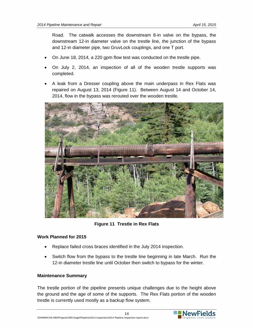
The 12-inch diameter HDPE line extends from the concrete OTP manhole (Figure 13) to the Garage manhole (Figure 14) in a wood stave pipe on a wooden trestle to a concrete vault near the Upper Surge Pond at the WTP. Figure 15 shows the downstream end of the trestle segment, the crossing over the river and Tigwon Road, and the upstream end of the OTP manhole to WTP segment.
Figure 13 OTP manhole, downstream is to the right
Two pipes leave the Upper Pond vault: a primary 10-inch diameter line to the Upper Pond and a secondary 12-inch diameter line with valves that can be used to direct flow
16 \\DHINRICHS-990\Projects\CBS Eagle\Pipeline\2014 Inspection\2014 Pipeline Inspection report.docx
2014 Pipeline Maintenance and Repair April 15, 2015
to either or both the Upper and Lower Ponds. Flow is usually directed to the Upper Pond through the 10-inch diameter pipe to a tailpipe suspended with barrel floats.
Figure 14 Garage Manhole looking downstream to location of WTP
Work Completed
• Using Dresser stainless steel repair couplings, small leaks 200 feet or so upstream of the Garage manhole were sealed off on January 2, 2014. These small leaks formed icicles in the winter.
• On July 2, 2014, the trestle-supported sections were inspected for failed or weakened posts and stringers.
• Sediment was periodically vacuumed from the Upper Pond vault.
• The tailpipe in the Upper Pond was jetted in November and pulled up out of the pond bottom sediments to relieve frequent plugging.
17 \\DHINRICHS-990\Projects\CBS Eagle\Pipeline\2014 Inspection\2014 Pipeline Inspection report.docx

2014 Pipeline Maintenance and Repair April 15, 2015
Figure 15 Trestle crossing Rex Flats (left) to WTP segment (right). Tigwon Road
crosses the photograph from right to left.
Work Planned for 2015
• Repair any additional small leaks that occur.
• Run flow tests and jet pipeline as needed to maintain flow.
• Vacuum sediment from the Upper Pond vault and the tailpipe in the Upper Pond as needed.
• Install a new double-wye cleanout port 200 feet downstream of OTP manhole on an elevated section.
• Repair failed or weakened posts and stringers in the trestle supported sections.
Maintenance Summary
About 60% of this segment was jetted in 2012 to loosen and remove scale that had collected over the years. Design grade was reestablished in 2012 by repairing sags. Both of these actions were important to putting this segment back into a condition where it would dependably carry greater than 250 gpm from the mine. No serious maintenance issues were noted in 2014.
18 \\DHINRICHS-990\Projects\CBS Eagle\Pipeline\2014 Inspection\2014 Pipeline Inspection report.docx

2014 Pipeline Maintenance and Repair April 15, 2015
10 CTP PIPELINES
Groundwater collected at the North and East extraction trenches at the CTP is pumped in a buried force main line to the Surge Ponds at the WTP. The 3000 foot long force main is constructed of 3-inch and 4-inch diameter HDPE pipe with five cleanouts identified in the diagrams as CO#1 - #5. The East extraction trench is connected to the force main near CO#3 by a 135-foot-long 3-in diameter HDPE line. Diagrams of the force main layout are presented in Appendix A.
Work Completed
• On June 18 and 19, 2014, the force main was jetted from CO#1 to the North extraction trench and from CO#1 to CO#2.
• On July 16, 2014, the force main was jetted from the outfall at the Surge Ponds to CO#3.
• On September 9, 2014, the surface plumbing at the East extraction trench was replaced, eliminating old steel pipe and adding a new cleanout. From the new cleanout, the short pipe segment from the East extraction trench to the force main was jetted. The T fitting on the force main shown on the drawings was not located.
Work Planned for 2015
• Monitor in-line pump pressure and flow rates for the East and North pumps.
• Monitor groundwater levels in monitoring well ET-1 at the East extraction trench to access groundwater capture.
• Continue to observe the river bank near the East extraction trench for any sign of groundwater seepage from the CTP.
Maintenance Summary
About 80% of the force main was jetted in 2013 to loosen and remove the soft iron scale that had collected over the years. This action increased flow rates and reduced the pump pressure required to move the extracted groundwater to the Surge Ponds. The 3-inch diameter pipeline from the East extraction trench to the force main (135 feet long) could not be accessed with the jet equipment in 2013. In 2014, additional jetting of the force main, replacement of the older East Trench plumbing, and jetting of the short East extraction trench line to the force main resulted in an additional increase in flow rates and reduced pump pressure.
19 \\DHINRICHS-990\Projects\CBS Eagle\Pipeline\2014 Inspection\2014 Pipeline Inspection report.docx

2014 Pipeline Maintenance and Repair April 15, 2015
11 BIBLIOGRAPHY
Borcherdt 1937. The Underground Mill at Gilman, Colorado. AIME Tech. Bul. 808.
NewFields 2013. 2012 Eagle Mine Pipeline Inspection and Maintenance Report, January, 2013.
NewFields 2014. 2013 Eagle Mine Pipeline Inspection and Maintenance Report, February 14, 2014.
URS 2011. Audit of Collection and Conveyance Systems for Eagle Mine, Minturn, CO. Prepared for EPA and CDPHE, January 2011.
20 \\DHINRICHS-990\Projects\CBS Eagle\Pipeline\2014 Inspection\2014 Pipeline Inspection report.docx

APPENDIX A
PIPELINE DRAWINGS AND SCHEMATICS

""
"
"""
$+"
#*
!(
!(
!(
!(
GF
!
!
!
!!
!(
!(
!(
!(
!(
!( !(
ADIT #143 (Approx.)
Tip-Top ADIT
Tip-Top MH
Existing Tip Top Transport Line (6")
Pump-Back Line
ADIT #6
MH 20
Waste Rock Pile (WRP) #8
ADIT #5
ADIT #8Fancy Shaft - Drains to Mine Pool
Lower WRP 8 Grouted Diversion Trench
Upper WRP 8 Runoff PipeADIT #7
Combined Seep and WRP 8 Runoff Line
Existing Mine Water Transport Line (10")
MDD Vault
Pump Back Building
New Bypass Pipeline (8")
OTP MH
CTP Groundwater Collection System
Water Treatment Plant
Upper Surge Pond
Lower Surge Pond
Decant Sump
MH-E
Electrical Controls
MH-N
North Groundwater Extraction Trench French Drain
East Groundwater Extraction Trench French Drain
Garage- MH
Steel Overpass
MH 0
MH 7
Mudslide MH
Signal MH
Dock at Belden MH
Wooden Trestle
Legend" ADIT
$+ Pump Back Building
" MDD Vault
#* Electrical Controls
!( Manholes
GF Fancy Shaft - Drains to Mine Pool
! Sumps
ADIT 6 LineCTP Groundwater Collection System
French DrainMDD LinesMDD ADIT 5 LineNew Bypass Line
Pump-Back LineSeepage Lines
WRP 8 DraingageBuried WRP 8 DraingageWater Transport LineBuried Water Transport Line
Lower Surge Pond; Upper Surge PondWaste Rock Pile (WRP) #8
Water Treatment Plant
SEEPAGE COLLECTION AND CONVEYANCE SYSTEMSEAGLE MINE
EAGLE COUNTY, COLORADO
Note: Dashed lines are buried; Solid lines are above ground