2014 EUVL Workshop Progress of Optical Design for … of Optical Design for EUV Lithography Tools in...
28
Progress of Optical Design for EUV Lithography Tools in BIT 2014 EUVL Workshop Yanqiu Li*, Zhen Cao, Fei Liu, Qiuli Mei, Yan Liu Beijing Institute of Technology , China June 25, 2014 E-mail:[email protected]
Transcript of 2014 EUVL Workshop Progress of Optical Design for … of Optical Design for EUV Lithography Tools in...
Progress of Optical Design for EUV
Lithography Tools in BIT
2014 EUVL Workshop
Yanqiu Li*, Zhen Cao, Fei Liu, Qiuli Mei, Yan Liu
Beijing Institute of Technology , China
June 25, 2014
E-mail:[email protected]

2
OUTLINE
Introduction
Design of EUV projection objective
Grouping design method
Design of co-axial objective systems
Design of off-axial objective systems
Design of EUV illuminator
Reverse design/adjustment method
Design results
Acknowledgment
2014/6/25 Beijing Institute of Technology Yanqiu Li (P56)
3
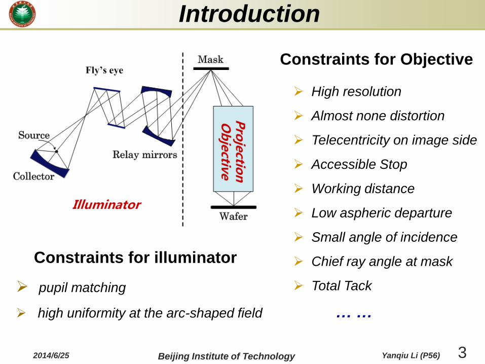
High resolution
Almost none distortion
Telecentricity on image side
Accessible Stop
Working distance
Low aspheric departure
Small angle of incidence
Chief ray angle at mask
Total Tack
Constraints for illuminator
pupil matching
high uniformity at the arc-shaped field
Introduction
Constraints for Objective
… …
2014/6/25 Beijing Institute of Technology Yanqiu Li (P56)

4
Introduction
Trend of NA for projection objective
1R SNA
kE
HP 45nm 32nm 22nm 16nm 11nm
NA0.25 0.83 0.59 0.41 0.30
NA0.30 0.71 0.49 0.36
NA0.33 0.78 0.54 0.39
NA0.35 0.83 0.57 0.41 0.29
NA0.40 0.65 0.47 0.33
NA0.45 0.73 0.53 0.37
NA0.50 0.81 0.59 0.41
NA0.60 0.71 0.49
NA0.70 0.83 0.57
ADT &
NXE 3100
NEX 3300
* New design forms are needed !
* New design strategy is required !
11nm node
8nm node
2014/6/25 Beijing Institute of Technology Yanqiu Li (P56)
5
Introduction
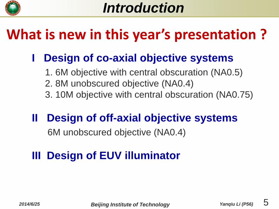
I Design of co-axial objective systems
1. 6M objective with central obscuration (NA0.5)
2. 8M unobscured objective (NA0.4)
3. 10M objective with central obscuration (NA0.75)
II Design of off-axial objective systems
6M unobscured objective (NA0.4)
III Design of EUV illuminator
2014/6/25 Beijing Institute of Technology Yanqiu Li (P56)
What is new in this year’s presentation ?

6
Grouping Design for EUVL Objective
Parameter calculation
condition
•Non-Obstruction condition
•Obscuration ratio condition
•Pupil-stop condition
•Conjugation condition
Grouping strategy (GS)
•GS for 6-mirror objective
•GS for 8-mirror objective
•GS for 10-mirror objective
Basic Group Database
•Object side group
•Image side group
•Obscured image side group
•Middle two mirrors group
•Middle four mirrors group
Spherical
initial structure
Connecting
rules
2014/6/25 Beijing Institute of Technology Yanqiu Li (P56)

7
Basic Mirror Groups
Basic mirror
groupsAll-sphere
initial structure
Five Kinds of Mirror Groups
Object side group (G1) Image side group (G3)
Middle two-mirror group (G2)
Wafer Wafer
Obsc-image group (G3’)
Middle four-mirror group (G2’)
kM
lM
mMnM
MASK
M 2
M1
M 3
M4
Connect
2014/6/25 Beijing Institute of Technology Yanqiu Li (P56)

8
6M unobscured objective:
G3
G2
G1Mask
WaferM1
M2
M3
M4
M5
M6
G3'
G2
G1Mask
M1
M2 M3
M4
M5
M6
WaferG1 : M1, M2
G2 : M3, M4
G3’: M5, M6
Grouping Strategy
G1: M1, M2
G2: M3, M4
G3: M5, M6
6M objective with central obscuration:
2014/6/25 Beijing Institute of Technology Yanqiu Li (P56)

9
M3M1M2
M4
M5M6
M7
M8
G1
G2'
G3Mask
Wafer G1 :M1, M2
G2’:M3, M4, M5, M6
G3 :M7, M8
8M unobscured objective
10M objective with central obscuration
M1M2
M3
M4
M6
M5
M8
M7
M9M10
Mask
Wafer
G1
G2'
G3' G3'
G1 :M1, M2
G2’:M3, M4, M5, M6
G3’:M7, M8
G3’:M9, M10
Grouping Strategy
2014/6/25 Beijing Institute of Technology Yanqiu Li (P56)

10
Parameter Calculation ConditionNon-obstruction condition: The radius of one mirror can be
expressed as a function of the clearance.
Clearance: The distance between the edge of a mirror and the beam
near it.
0arctan /sin( ) .
2 2
ai a i iaii ai
h h CL dUc h
aiU the slope angle of the upper
marginal ray on
aih the ray height of the upper
marginal ray on
0ah the ray height of the ray beam
near
iM
iM
1iM
2014/6/25 Beijing Institute of Technology Yanqiu Li (P56)

11
the diameter ratio of the hole
to the mirror
Parameter Calculation ConditionObscuration Ratio condition: The radius of one mirror can be
expressed as a function of the ratio of hole to whole mirror diameter.
aiU the slope angle of upper marginal
ray of
aih height of upper marginal ray of iM
Mi(Di)
Mi+1(Di+1)hai
-di
WDI
haDi+1-Uai
arctan ( - 2 + ) / (- )= sin -
2 2
aDi+1 i 1 aDi+1 ai iaii ai
h radio h h dUc h
iM
aDih height of upper marginal ray of the
virtual surfaceiD
iradio
iM
2014/6/25 Beijing Institute of Technology Yanqiu Li (P56)

12
Pupil-stop condition: Surface parameter is the function of the
pupil or stop position .
ztU
zth
sd
sM
1sM
STOP
zs zsarctan /sin( ) .
2 2
s zts zs
h d z Uc h
zsh chief ray height on sM
sd separation between and1sM
ztU slope angle of the chief ray on
zsz the along optical axial distance
of the incident point on sM
sM
sM
Parameter Calculation Condition
2014/6/25 Beijing Institute of Technology Yanqiu Li (P56)

13
Conjugation condition: Surface parameters should match the
adjacent groups’ properties (e.g. petzval sum, object-image, Magification,
pupil matching).
al
ad
bl
pbl
pal
aM
bM
2 2
1 1 1
2
2
1 1
4
14
2
2
a a a a pa pb
a
a pb pa pa pb pa pb
b a
b b b a a b
d l l l Ml l ps A ps A AB A
c ps ps B A
d A Ml l M l Ml psl l
c ps c
d l l TT l d l
+
+
2 2
2 2 2 2 2 4 2 2
2
1 1 1
2 4 4
pb pa pa pb pa pb pa pb pa pb
pa pb pb pa pa pb
A Ml l l M TT M l l Ml l l l l TT
B ps M l l M l l M l l
+
2 2 4 0ps A AB M
ps
denotes the magnification
of the middle two mirror group
denotes the pezval sum of it
Parameter Calculation Condition
2014/6/25 Beijing Institute of Technology Yanqiu Li (P56)

14
Design of co-axial objective systems
NA 0.3
MAGNIFICATION 1/4
TOTAL TRACK 1530mm
NA 0.3
MAGNIFICATION 1/4
TOTAL TRACK 1280mm
6M unobscured objective
—presented in 2013 EUVL work shop
NA 0.3
MAGNIFICATION 1/4
TOTAL TRACK 1239mm
2014/6/25 Beijing Institute of Technology Yanqiu Li (P56)

15
1. 6M objective with central obscuration
G3’ is calculated under obscuration ratio condition firstly.
G2 is then calculated under non-obstruction condition.
To match the ray path of G2 and G3’, G1 can be determined
under conjugation condition.
Our latest design form
To enable 11nm node, 6-mirror with central obscuration is one of the
solutions. The NA of the objective is around 0.45.
Design of co-axial objective systems
2014/6/25 Beijing Institute of Technology Yanqiu Li (P56)

16
Performance Wavelength 13.5nm
Numerical aperture 0.5
A field of view 13mm×1mm
Reduction 8
Total track 1630mm
working distance 34mm
Chief ray angle on
mask<6.0°
Chief ray angle on
wafer0.01°
Wavefront error (RMS) 0.0285λ
Distortion <1.2nm
Pupil obscuration <25%
10:25:36
1.0
0.9
0.8
0.7
0.6
0.5
0.4
0.3
0.2
0.1
MODULATION
8760 17520 26280 35040 43800 52560 61320 70080
SPATIAL FREQUENCY (CYCLES/MM)
R
T
New lens from CVMACR
O:cvnewlens.seq
DIFFRACTION SQ WAVE RESPONSE
04-Jun-14
DIFFRACTION LIMIT T R
0.9 FIELD ( )5.67 O
T R
0.9 FIELD ( )5.84 O
T R
1.0 FIELD ( )6.02 O
T R
1.0 FIELD ( )6.20 O
T R
1.0 FIELD ( )6.39 O
WAVELENGTH WEIGHT
13.5 NM 1
DEFOCUSING 0.00000
1 mm
13 mm
Y
XZ
Ring field
Design of co-axial objective systems
2014/6/25 Beijing Institute of Technology Yanqiu Li (P56)

17
Generation of new design forms
• G3’ is fixed. Changing the separations of mirrors in G2, new
design forms of G2 will be obtained.
•To connect G2 and G3, the design forms of G1 will be
changed accordingly.
•A new initial design are obtained by connecting the three
groups.
Other design forms
Design of co-axial objective systems
2014/6/25 Beijing Institute of Technology Yanqiu Li (P56)

18
2. 8M unobscured objective
NA 0.4
Reduction 4
TOTAL TRACK 947mm
NA 0.4
Reduction 4
TOTAL TRACK 1235mm
NA 0.4
Reduction 4
TOTAL TRACK 1274mm
Design of co-axial objective systems
2014/6/25 Beijing Institute of Technology Yanqiu Li (P56)
19
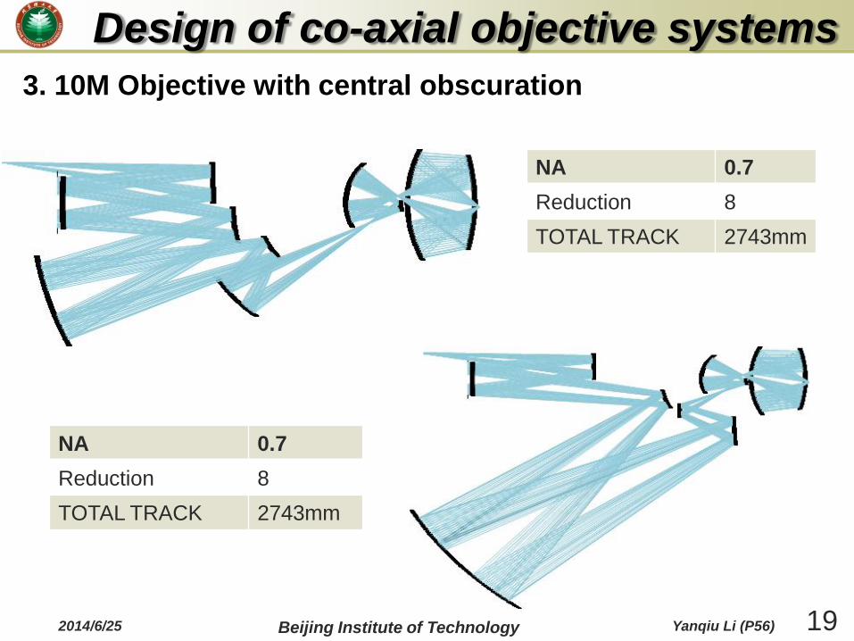
NA 0.7
Reduction 8
TOTAL TRACK 2743mm
NA 0.7
Reduction 8
TOTAL TRACK 2743mm
3. 10M Objective with central obscuration
Design of co-axial objective systems
2014/6/25 Beijing Institute of Technology Yanqiu Li (P56)
20
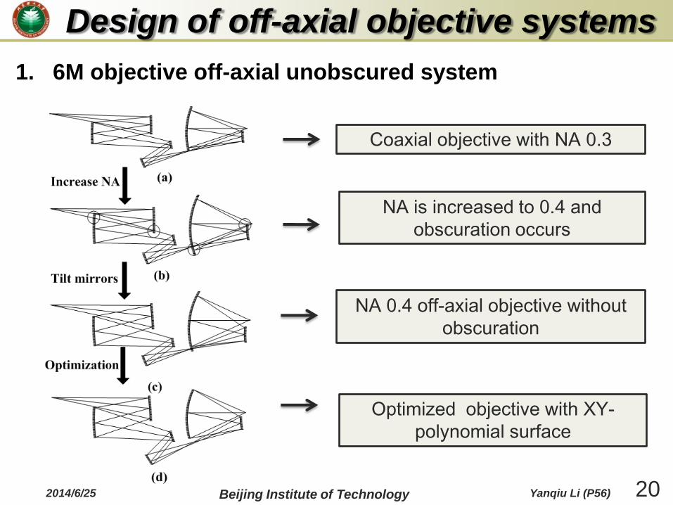
Coaxial objective with NA 0.3
NA is increased to 0.4 and
obscuration occurs
NA 0.4 off-axial objective without
obscuration
Optimized objective with XY-
polynomial surface
Design of off-axial objective systems
1. 6M objective off-axial unobscured system
2014/6/25 Beijing Institute of Technology Yanqiu Li (P56)

21
1.5mm
26 mm
29mmY
XZ
21:39:36
1.0
0.9
0.8
0.7
0.6
0.5
0.4
0.3
0.2
0.1
MODULATION
6825 13650 20475 27300 34125 40950 47775 54600
SPATIAL FREQUENCY (CYCLES/MM)
X
Y
New lens from CVMACR
O:cvnewlens.seq
DIFFRACTION SQ WAVE RESPONSE
14-Jan-14
DIFFRACTION LIMIT Y X
(-1.31,-6.11) DEG
Y X
(-1.31,-6.22) DEG
Y X
(-1.97,-5.91) DEG
Y X
(-1.97,-6.01) DEG
Y X
(-1.97,-6.12) DEG
WAVELENGTH WEIGHT
13.4 NM 1
DEFOCUSING 0.00000
Rectangular field
Wavelength 13.5nm
Numerical aperture 0.4
A field of view 26mm×1.5mm
Reduction 4
Total track 1263mm
working distance 35mm
Chief ray angle on
mask<6.0°
Chief ray angle on
wafer0.18°
Wavefront error (RMS) 0.034λ
Distortion 1.8nm
Design of off-axial objective systems
Performance
2014/6/25 Beijing Institute of Technology Yanqiu Li (P56)
22
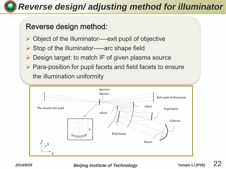
Reverse design/ adjusting method for illuminator
Collector
Pupil facets
Field facets
relay1
relay2
(Reticle)
The dummy exit pupil
Source
Exit pupil of illuminator
Aperture
Z
YX
R
Reverse design method:
Object of the illuminator----exit pupil of objective
Stop of the illuminator-----arc shape field
Design target: to match IF of given plasma source
Para-position for pupil facets and field facets to ensure
the illumination uniformity
2014/6/25 Beijing Institute of Technology Yanqiu Li (P56)

23
Reverse adjusting method:
A adjusting method for illuminator to match objectives with
different NA and pupil parameters.
Only the position of the component is adjusted. The figure of
the component is the same.
Item Set 1 Set 2 Set 3
Wavelength 13.5nm
Exposure field on the reticle
104mm 6mm, R=119mm
Chief ray angle on the reticle
5.52 degree 6 degree 4.9 degree
demagnification 1/4 1/4 1/4
NA in image space 0.25 0.3 0.33
Reverse design/ adjusting method for illuminator
2014/6/25 Beijing Institute of Technology Yanqiu Li (P56)

24
Collector
Pupil facets
Field facets
The first relay
mirror
The second relay
mirror
reticle
Exit pupil
IF
Source
90-degree
dipole
illumination
45-degree
quadrupole
illumination
annular
illumination
Pupil
facets
Exit
pupil
Reverse design method for illumination system
The illumination uniformity is better than 2.5%.
2014/6/25 Beijing Institute of Technology Yanqiu Li (P56)

25
Fei Liu received the BS degree in measurement and control
technology and instruments from Changchun University of Science
and Technology in 2008. She is currently a PhD candidate directed
by Professor Yanqiu Li in the School of Optoelectronics at Beijing
Institute of Technology. Her current interests include optical system
design for EUVL.
Zhen Cao (Speaker) received the BS degree in optoelectronic
information engineering from Xi’an Technological University in
2008. He is currently works at Beijing Institute of Technology. His
current interests include optical system design for EUVL.
Yanqiu Li received the MS and PhD degrees in optics from Harbin
Institute of Technology. She worked as a director of the micro- and
nano-fabrication division at Institute of Electrical Engineering
Chinese Academy of Science, as a senior engineer at Nikon, as an
invited professor of Tohoku University of Japan, and as a frontier
researcher at RIKEN of Japan. She is currently a professor of School
of Optoelectronics at Beijing Institute of Technology, Beijing, China.
Members of our EUV team
2014/6/25 Beijing Institute of Technology Yanqiu Li (P56)
26
Yan Liu received the BS degree in Optoelectronic information
engineering from Changchun University of Science and technology
in 2010. He is currently a PhD candidate directed by Professor
Yanqiu Li in the School of Optoelectronics at Beijing Institute of
Technology. His current interests include optical system design for
EUVL.
Xinli Liang received the BS degree in optical information science
and technology from Nanjing University of Aeronautics and
Astronautics in 2012. She is currently a MS candidate directed by
Professor Yanqiu Li in the School of Optoelectronics at Beijing
Institute of Technology. His current interests include design of
illumination system for EUVL.
Qiuli Mei received her BS degree in optical information science and
technology from Wuhan university of technology in 2010. She is
currently a PHD candidate in the School of Optoelectronics at
Beijing Institute of Technology. Her current interests involve design
of illumination system and the applications of free form surface in
non-imaging optics.
2014/6/25 Beijing Institute of Technology Yanqiu Li (P56)

27
Acknowledgment
This work is supported by
National Science and Technology Major Project.
视场复眼
光阑复眼
中继镜组
掠入射镜
掩模
出瞳
椭圆聚光镜
2014/6/25 Beijing Institute of Technology Yanqiu Li (P56)

282014/6/25 Beijing Institute of Technology Yanqiu Li (P56)


![EUVL Symposium HVM FINAL 2004[1]](https://static.fdocuments.net/doc/165x107/55c513d9bb61ebc37e8b4574/euvl-symposium-hvm-final-20041.jpg)