
2013 Wright Specifications Catalog
189
Welcome! P+%!% !% 6 %+%#) "%+ view, search print ACCO M!%)!+ H!$+)' S+) WRIGHT 7 SPEEDWA 7 !$ WRIGHT 7 WORK-RATED 7 /$# /!'%. C+)# )% ! #/+%% +) & WORK-RATED 7 /%#)&)#!) /!'% VIEW C+)# )% ! #/+%% +) & SPEEDWA 7 /%#)&)#!) /!'% VIEW C+)# /). E% (% &++)' /!'% !'% (% /))': SPEEDWAY Specification pages: Print pages 5 to 47 WORK-RATED Specification pages: Print pages 48 to 189 PRINT ® THE NEW CENTURY SERIES ® H O I S T S 7 7 C+)# %!#( "6 MODEL NUMBER When searching for Monorail and Close Headroom Cross-Mounted Monorail hoists: R%/+!#% L, P , G M ) (% MODEL NUMBER )( ! !%) * T %!#( & M$%+ N"%: C1W03S020-15P4S0 E% (% &++)': C1W03S020-15*4S0 SEARCH 1T to 25T 1T to 5T C!# I&!)
Transcript of 2013 Wright Specifications Catalog

8/21/2019 2013 Wright Specifications Catalog
http://slidepdf.com/reader/full/2013-wright-specifications-catalog 1/189
Welcome!P+%!% !% 6 %+%#) "%+ view, search print
ACCO M!%)!+ H!$+)' S+) WRIGHT7 SPEEDWA7 !$
WRIGHT7 WORK-RATED7 /$# /!'%.
C+)# )% ! #/+%% +) &
WORK-RATED7 /%#)&)#!) /!'%
VIEW
C+)# )% ! #/+%% +) &
SPEEDWA7 /%#)&)#!) /!'%
VIEW
C+)# /). E% (% &++)' /!'% !'% (% /))':
SPEEDWAY Specification pages: Print pages 5 to 47
WORK-RATED Specification pages: Print pages 48 to 189
®
THE NEW CENTURY SERIES® H O I S T S
7
7
C+)# %!#( "6 MODEL NUMBER
When searching for Monorail and Close Headroom Cross-Mounted Monorail hoists:
R%/+!#% L, P, G M ) (% MODEL NUMBER )( ! !%) *T %!#( & M$%+ N"%: C1W03S020-15P4S0
E% (% &++)': C1W03S020-15*4S0
SEARCH
1T to 25T
1T to 5T
C!# I&!)

8/21/2019 2013 Wright Specifications Catalog
http://slidepdf.com/reader/full/2013-wright-specifications-catalog 2/189
WORK-RATED® INDEX SEARCH HOME SCREEN
SPEEDWAY Monorail Hoists
F+'+ '* (++
1 " !+ +++* !+))'
2 " !+ +++* !+))'
3 " !+ +++* !+))'
4 " !+ +++* !+))'
1 " D(+ +++* !+))'
2 " D(+ +++* !+))'
3 " D(+ +++* !+))'
5 " D(+ +++* !+))'
SPEEDWAY Close Headroom Cross Mounted Hoists
F+'+ '* (++
1 " D(+ +++* !+))'
2 " D(+ +++* !+))'
3 " D(+ +++* !+))'
5 " D(+ +++* !+))'
SPEEDWAY Top Running Trolley Hoists
F+'+ '* (++
1 " !+ +++* !+))'
2 " !+ +++* !+))'
3 " !+ +++* !+))'
4 " !+ +++* !+))'
1 " D(+ +++* !+))'
2 " D(+ +++* !+))'
3 " D(+ +++* !+))'5 " D(+ +++* !+))'
SPEEDWAY Deck Mounted Hoists
F+'+ '* (++
1 " !+ +++* !+))'
2 " !+ +++* !+))'
3 " !+ +++* !+))'
4 " !+ +++* !+))'
1 " D(+ +++* !+))'
2 " D(+ +++* !+))'
3 " D(+ +++* !+))'
5 " D(+ +++* !+))'
SPEEDWAY Base Mounted Winches
F+'+ '* (++
1/2 " !+ +++* !+))'
1 " !+ +++* !+))'
1/2 " D(+ +++* !+))'1 " D(+ +++* !+))'
1-1/2 " D(+ +++* !+))'
C) +; C) +;
C') I'
®
THE NEW CENTURY SERIES® H O I S T S
>
1T to 5T

8/21/2019 2013 Wright Specifications Catalog
http://slidepdf.com/reader/full/2013-wright-specifications-catalog 3/189
SPEEDWAY® INDEX SEARCH HOME SCREEN
>
C') I'
WORK-RATED Monorail Hoists
F+'+ '* (++1 " !+ +++* !+))'
2 " !+ +++* !+))'3 " !+ +++* !+))'
5 " !+ +++* !+))'7-1/2 " !+ +++* !+))'
10 " !+ +++* !+))'15 " !+ +++* !+))'20 " !+ +++* !+))'
1 " D(+ +++* !+))'
2 " D(+ +++* !+))'3 " D(+ +++* !+))'
5 " D(+ +++* !+))'7-1/2 " D(+ +++* !+))'10 " D(+ +++* !+))'
15 " D(+ +++* !+))'20 " D(+ +++* !+))'
25 " D(+ +++* !+))'
WORK-RATED Close Headroom Cross Mounted Hoists
F+'+ '* (++1 " D(+ +++* !+))'
2 " D(+ +++* !+))'
3 " D(+ +++* !+))'5 " D(+ +++* !+))'
7-1/2 " D(+ +++* !+))'10 " D(+ +++* !+))'
WORK-RATED Top Running Trolley Hoists
F+'+ '* (++
1 " !+ +++* !+))'2 " !+ +++* !+))'
3 " !+ +++* !+))'5 " !+ +++* !+))'
7-1/2 " !+ +++* !+))'10 " !+ +++* !+))'15 " !+ +++* !+))'
20 " !+ +++* !+))'
1 " D(+ +++* !+))'2 " D(+ +++* !+))'
3 " D(+ +++* !+))'5 " D(+ +++* !+))'7-1/2 " D(+ +++* !+))'
10 " D(+ +++* !+))'15 " D(+ +++* !+))'
20 " D(+ +++* !+))'25 " D(+ +++* !+))'
WORK-RATED Deck Mounted Hoists
F+'+ '* (++1 " !+ +++* !+))'
2 " !+ +++* !+))'3 " !+ +++* !+))'
5 " !+ +++* !+))'7-1/2 " !+ +++* !+))'
10 " !+ +++* !+))'15 " !+ +++* !+))'20 " !+ +++* !+))'
1 " D(+ +++* !+))'
2 " D(+ +++* !+))'3 " D(+ +++* !+))'
5 " D(+ +++* !+))'7-1/2 " D(+ +++* !+))'10 " D(+ +++* !+))'
15 " D(+ +++* !+))'20 " D(+ +++* !+))'
25 " D(+ +++* !+))'
WORK-RATED Base Mounted Winches
F+'+ '* (++1 " !+ +++* !+))'
1-1/2 " !+ +++* !+))'
2-1/2 " !+ +++* !+))'3-3/4 " !+ +++* !+))'
5 " !+ +++* !+))'
1 " D(+ +++* !+))'1-1/2 " D(+ +++* !+))'
2-1/2 " D(+ +++* !+))'3-3/4 " D(+ +++* !+))'5 " D(+ +++* !+))'
6-1/4 " D(+ +++* !+))'
C) +; C) +;
1T to 25T

8/21/2019 2013 Wright Specifications Catalog
http://slidepdf.com/reader/full/2013-wright-specifications-catalog 4/189
SEARCH HOME SCREEN
C') I'
ACCO Material Handling Solutions
P.O. B< 792
&, PA 17405
P+: 800-967-7333F'<: 800-715-8897
www.accomhs.com

8/21/2019 2013 Wright Specifications Catalog
http://slidepdf.com/reader/full/2013-wright-specifications-catalog 5/189
SPEEDWAY® INDEX SEARCH HOME SCREEN
Electric Wire Rope HoistsIssued 06-01-12
Wright family of SPEEDWAY hoists is a complete line of electric wire
rope hoists. It is an advanced design incorporating the most recentmaterials and concept. The most current duty cycle and safety
requirements of users are built into this line, not added on.
CONSTRUCTION FEATURES:
CONTROLS: Choose from single, 2-speed, or inverter. Controls are
magnetic reversing type, mechanically and electrically interlocked
with 115 volt control circuit. All wiring conforms to applicable NEC
requirements. Motor thermostats are standard providing motor
running overcurrent protection. NEMA Type 3R enclosures are
standard. Cover is lightweight, tough ABS material, deep-drawn for
maximum control accessibility.
PUSH BUTTON STATION: Push button stations are not furnished as
standard equipment with these hoists. Push button station drop of
cord & strain chain are available as optional equipment. See
Accessories Section. Specify required drop.
MOTOR: Standard NEMA C face mounting, TENV, Class F
insulation, 30-minute duty motor is provided for standard commercial
power supplies. The motor has a standard NEMA shaft extension.
GEAR TRAIN: Quiet, helical and spur gearing. All gears are machine
cut, case-hardened alloy steel with shock-resistant ductile cores.
Gearing is designed to AGMA standards for maximum life,
and operates in an oil bath. Rugged aluminum alloy housing provides
rapid heat dissipation.
BEARINGS - SPIDER RETAINER: Precision heavy-duty ball
bearings support all shafts. Bearings at outboard end of shafts are
held in place by a heavy-duty Spider Retainer. This allows removal of
Gear Housing Cover for inspection (after draining oil). All internal
parts remain in place and can be operated for inspection.
DRUM: The large diameter steel drum has machined grooves and
large flanges. At least two full turns of rope remain on the drum at the
lowest hook position of rated lift. .
LOAD BLOCK- HOOK: Drop forged heat-treated steel hook swivels
360˚ on a shielded roller thrust bearing and comes equipped with a
spring latch. Work can be performed on the load block
without removing wire rope from drum. Sheaves are machined steel.
WIRE ROPE: Pre-formed wire rope, of hoisting service construction,
has swaged fittings on both ends for ease of replacement if
necessary.
MECHANICAL LOAD BRAKE: Automatic Weston-type multiple disc
brake. It can hold a full capacity load independent of motor brake and
assures that the load does not accelerate while being lowered.
Adjustment is not required.
MOTOR BRAKE: Proven in millions of hours of in-service operation
the original Wright A-C magnet-actuated disc brake delivers rapidstops with virtually no hook drift. Rated a minimum of 150% of full loa
motor torque.
LIMIT SWITCH: A gravity-type upper hook travel limit switch is
provided. The unit is equipped with an automatic momentary lowerin
circuit. An optional geared limit switch is also available.
TROLLEY FRAME: The trolley frame shall be built of steel and
precision machined to assure proper alignment of trolley wheels and
drives.
TROLLEY WHEELS: 1 to 2 ton trolley wheels are heat treated gray
iron. Each wheel supported on anti-friction bearings suitable to take
radial and thrust loads. The trolley wheels have crowned treads for
operation on tapered or flat flange beams. The wheels shall be
lubricated at the factory with sodium base grease.
TROLLEY WHEELS: 3 and 5 ton trolley wheels shall have tread
surfaces machined and hardened to 375-425 Brinell. Each wheel sh
be supported on anti-friction bearings suitable to take radial and thru
loads. The wheels shall be lubricated at the factory with sodium base
grease. The trolley wheels have dual tread for operation on tapered
flat flange beams. Wheel treads shall be smooth, true and uniform
within .010 inch tread diameter on all wheels.
TROLLEY DRIVE: The trolley drive shall be a right angle worm gear
reducer fully enclosed with a steel worm and bronze worm wheel
designed to AGMA standards. The final gear reduction at trolley
wheels will be spur gears and will be open. The trolley drive motor sh
be TENV 30 minute duty with class F insulation and NEMA C face
mounting. A spring set A.C. disc type brake is available as optional
equipment.
TROLLEY CONTROLS: Choose from single, 2-speed, or inverter.
Single and 2-speed controls are available with ACM solid state cush
start for smooth travel motion and excellent load control as
optional equipment.
OPTIONAL OVERLOAD CUTOFF:
Protects load, hoist and operator by interrupting raising circuit when
hoist senses a damaging overload. When lifting circuit is interrupted
the lowering circuit remains intact to allow the load to be lowered and
removed. After the overload is removed the lifting circuit is
automatically restored. Overload Cutoff is accessible for field
adjustments.
Monorail Hoist
Features & Benefits 1TO 5 TON
Equipment described herein is not designed for, and should not be used for, lifting, supporting, or transporting humans. Modifications to upgrade, rerate, orotherwise alter the hoist or crane equipment shall be authorized only by the original manufacturer or qualified professional engineer. Failure to comply with anyone of the limitations noted herein may result in serious bodily injury.© 2012 ACCO Material Handling Solutions
800-967-7333 www.accomhs.com

8/21/2019 2013 Wright Specifications Catalog
http://slidepdf.com/reader/full/2013-wright-specifications-catalog 6/189
SPEEDWAY® INDEX SEARCH HOME SCREEN
Electric Wire Rope HoistsIssued 06-01-12
Some applications require that the load, when being lifted, not
move right or left from hoist centerline. If this requirement isknown, a true vertical lift hoist must be used. These are described
as double reeved.
3. SPECIFY PROPER MODEL NUMBER in regard to hoist.
Capacity, lifting speed, mounting and hoist control found in the
following pages.
4. SPECIFY MOTOR VOLTAGE: Wright standard motors are
available in 200/230/460/575-3-60 power with Class F insulation,
and are totally enclosed non-ventilated. Control is furnished as
standard equipment. Additional motor and control accessories are
found in the Accessories Section.
5. SPECIFY BEAM FLANGE WIDTH: SPEEDWAY trolleys are
adjustable for Standard I beam or WF beam, 4 inch to 11 inch
flange width. Beam size must be specified. Trolleys are alsoavailable for 3.25 or 3.33" patented track beams. Trolleys for WF
beams with flange widths greater than 11 inches available. See
Accessories. All reference to beam flange widths are for clearance
purposes only and do not imply that lower flange of beam will
support hoist with load.
6. SPECIFY OTHER MODIFICATIONS AND ACCESSORIES.
7. SPECIAL APPLICATION HOISTS: Contact your nearest
Wright representative.
8. FOR CURVED TRACK APPLICATION, CONTACT FACTORY.
9. ACCO RESERVES THE RIGHT TO MAKE CHANGES TO
THIS CATALOG AS MAY BE DEEMED NECESSARY.
Monorail HoistFeatures & Benefits 1TO 5 TON
Equipment described herein is not designed for, and should not be used for, lifting, supporting, or transporting humans. Modifications to upgrade, rerate, orotherwise alter the hoist or crane equipment shall be authorized only by the original manufacturer or qualified professional engineer. Failure to comply with anyone of the limitations noted herein may result in serious bodily injury.© 2012 ACCO Material Handling Solutions
800-967-7333 www.accomhs.com
HOW TO SPECIFY A SPEEDWAY HOIST
1. DETERMINE THE CAPACITY, LIFTING SPEED AND LIFTING
DISTANCE.
2. DETERMINE THE REEVING REQUIRED FOR YOUR
APPLICATION. SPEEDWAY hoists may be reeved in various ways to
gain desired mechanical advantages ... capacity, lifting distance, and
lifting speeds.
Reeving terminology is either "single" or "double" which refers to the
number of wire ropes coming from the drum.
Another word is "part" which refers to the mechanical advantage gained
by multiple reeving. For example, with 2 part single reeving (2 PS) the
load is distributed over the two parts and the mechanical advantage
doubles the capacity of one part reeving and reduces by one half the
lifting or lowering speed of the hook.
Reeving changes hoist arrangement to the beam or track, minimum
headroom distance, and lateral hook travel.

8/21/2019 2013 Wright Specifications Catalog
http://slidepdf.com/reader/full/2013-wright-specifications-catalog 7/189
SPEEDWAY® INDEX SEARCH HOME SCREEN
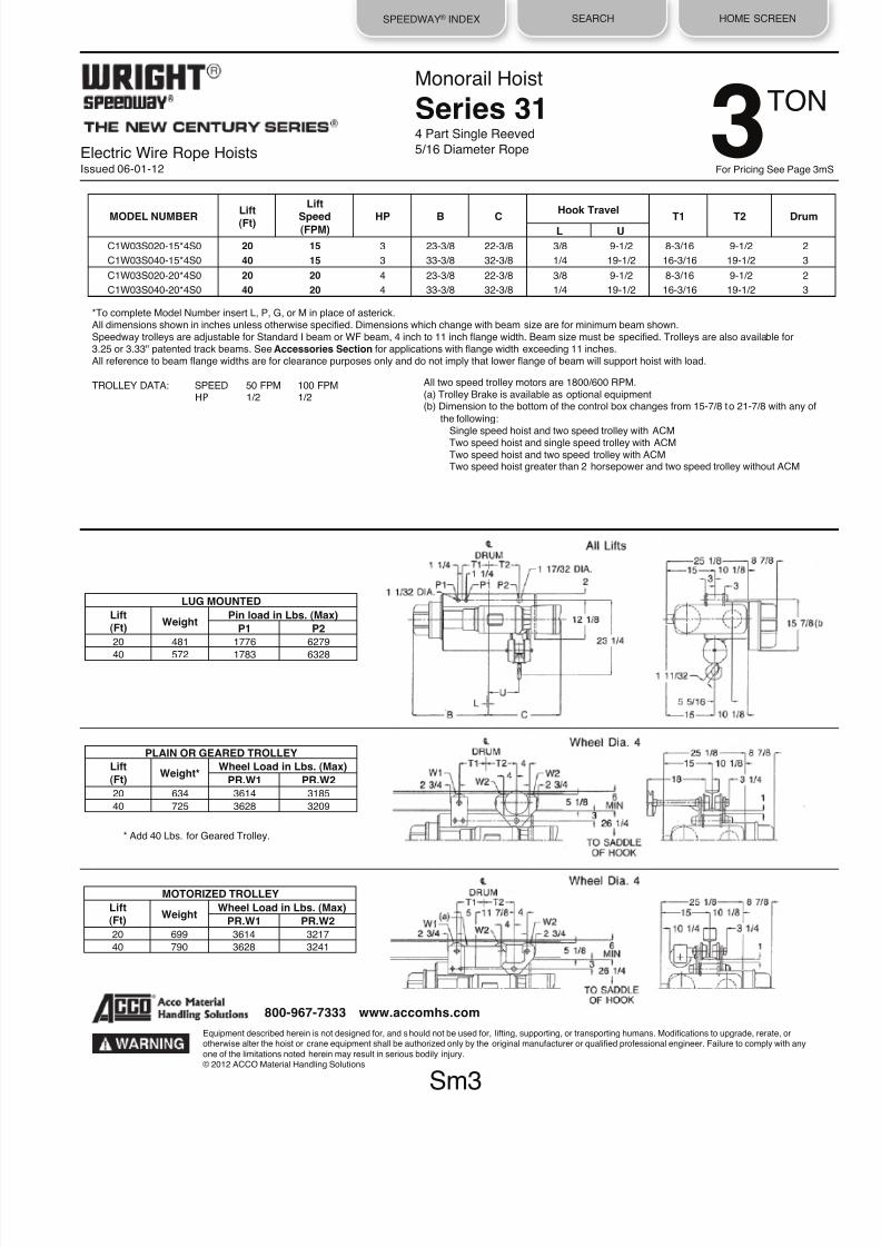
* Add 40 Lbs. for Geared Trolley.
Sm1
Equipment described herein is not designed for, and should not be used for, lifting, supporting, or transporting humans. Modifications to upgrade, rerate, orotherwise alter the hoist or crane equipment shall be authorized only by the original manufacturer or qualified professional engineer. Failure to comply with any
one of the limitations noted herein may result in serious bodily injury.© 2012 ACCO Material Handling Solutions
800-967-7333 www.accomhs.com
All two speed trolley motors are 1800/600 RPM.
(a) Trolley Brake is available as optional equipment(b) Dimension to the bottom of the control box changes from 17-1/8 to 23-1/4 with any of
the following:Single speed hoist and two speed trolley with ACM
Two speed hoist and single speed trolley with ACMTwo speed hoist and two speed trolley with ACMTwo speed hoist greater than 2 horsepower and two speed trolley without ACM
LUG MOUNTED Lift(Ft) Weight Pin Load in Lbs. (Max)
P1 P2 26 380 2269 2162 59 440 719 2267 107 527 705 2308
PLAIN OR GEARED TROLLEY Lift(Ft) Weight* Wheel Load in Lbs. (Max)
PR.W1 PR.W2 26 435 2027 1946 59 510 1459 1159 107 597 1430 1179
MOTORIZED TROLLEY Lift(Ft) Weight Wheel Load in Lbs. (Max)
PR.W1 PR.W2 26 500 2060 1979 59 575 1459 1191
107 662 1430 1212
Electric Wire Rope HoistsIssued 06-01-12
Monorail Hoist
Series 312 Part Single Reeved
1/4 Diameter Rope
MODEL NUMBERLift
(Ft)
Lift
Speed(FPM)
HP B CHook Travel
T1 T2 DrumL U
C1W01S026-15*2S0 26 15 1 16-3/8 15-3/8 15/16 4-7/16 - - 1
C1W01S059-15*2S0 59 15 1 23-3/8 22-3/8 15/16 11-7/16 8-3/16 11-3/8 2
C1W01S107-15*2S0 107 15 1 33-3/8 32-3/8 15/16 21-7/16 16-3/16 21-3/8 3
C1W01S026-20*2S0 26 20 2 16-3/8 15-3/8 15/16 4-7/16 - - 1
C1W01S059-20*2S0 59 20 2 23-3/8 22-3/8 15/16 11-7/16 8-3/16 11-3/8 2
C1W01S107-20*2S0 107 20 2 33-3/8 32-3/8 15/16 21-7/16 16-3/16 21-3/8 3
C1W01S026-30*2S0 26 30 2 16-3/8 15-3/8 15/16 4-7/16 - - 1
C1W01S059-30*2S0 59 30 2 23-3/8 22-3/8 15/16 11-7/16 8-3/16 11-3/8 2
C1W01S107-30*2S0 107 30 2 33-3/8 32-3/8 15/16 21-7/16 16-3/16 21-3/8 3
C1W01S026-40*2S0 26 40 3 16-3/8 15-3/8 15/16 4-7/16 - - 1
C1W01S059-40*2S0 59 40 3 23-3/8 22-3/8 15/16 11-7/16 8-3/16 11-3/8 2
C1W01S107-40*2S0 107 40 3 33-3/8 32-3/8 15/16 21-7/16 16-3/16 21-3/8 3
TON1For Pricing See Page 1m
*To complete Model Number insert L, P, G, or M in place of asterick.
All dimensions shown in inches unless otherwise specified. Dimensions which change with beam size are for minimum beam shown.Speedway trolleys are adjustable for Standard I beam or WF beam, 4 inch to 11 inch flange width. Beam size must be specified. Trolleys are also available for3.25 or 3.33" patented track beams. See Accessories Section for applications with flange width exceeding 11 inches.All reference to beam flange widths are for clearance purposes only and do not imply that lower flange of beam will support hoist with load.
TROLLEY DATA: SPEED 50 FPM 100 FPM
HP 1/2 1/2

8/21/2019 2013 Wright Specifications Catalog
http://slidepdf.com/reader/full/2013-wright-specifications-catalog 8/189
SPEEDWAY® INDEX SEARCH HOME SCREEN
* Add 40 Lbs. for Geared Trolley.
Electric Wire Rope HoistsIssued 06-01-12
Monorail Hoist
Series 312 Part Single Reeved
5/16 Diameter Rope
All two speed trolley motors are 1800/600 RPM.
(a) Trolley Brake is available as optional equipment(b) Dimension to the bottom of the control box changes from 15-7/8 to 21-7/8 with any of
the following:
Single speed hoist and two speed trolley with ACMTwo speed hoist and single speed trolley with ACMTwo speed hoist and two speed trolley with ACMTwo speed hoist greater than 2 horsepower and two speed trolley without ACM
LUG MOUNTED
Lift(Ft) Weight Pin Load in Lbs. (Max)
P1 P2 22 398 4148 3900 50 463 1375 4246 90 552 1319 4303
PLAIN OR GEARED TROLLEY Lift(Ft) Weight* Wheel Load in Lbs. (Max)
PR.W1 PR.W2 22 496 3709 3524 50 616 2819 2169 90 705 2700 2197
MOTORIZED TROLLEY Lift(Ft) Weight Wheel Load in Lbs. (Max)
PR.W1 PR.W2 22 561 3712 3556 50 681 2819 2201 90 770 2700 2230
Sm2
Equipment described herein is not designed for, and should not be used for, lifting, supporting, or transporting humans. Modifications to upgrade, rerate, orotherwise alter the hoist or crane equipment shall be authorized only by the original manufacturer or qualified professional engineer. Failure to comply with anyone of the limitations noted herein may result in serious bodily injury.© 2012 ACCO Material Handling Solutions
800-967-7333 www.accomhs.com
MODEL NUMBER
Lift
(Ft)
Lift
Speed(FPM)
HP B C
Hook Travel
T1 T2 DrumL U
C1W02S022-15*2S0 22 15 2 16-3/8 15-3/8 1 4-7/16 - - 1
C1W02S050-15*2S0 50 15 2 23-3/8 22-3/8 1 11-7/16 8-3/16 11-7/16 2
C1W02S090-15*2S0 90 15 2 33-3/8 32-3/8 1 21-7/16 16-3/16 21-7/16 3
C1W02S022-20*2S0 22 20 3 16-3/8 15-3/8 1 4-7/16 - - 1
C1W02S050-20*2S0 50 20 3 23-3/8 22-3/8 1 11-7/16 8-3/16 11-7/16 2
C1W02S090-20*2S0 90 20 3 33-3/8 32-3/8 1 21-7/16 16-3/16 21-7/16 3
C1W02S022-30*2S0 22 30 4 16-3/8 15-3/8 1 4-7/16 - - 1
C1W02S0S0-30*2S0 50 30 4 23-3/8 22-3/8 1 11-7/16 8-3/16 11-7/16 2
C1W02S090-30*2S0 90 30 4 33-3/8 32-3/8 1 21-7/16 16-3/16 21-7/16 3
TON 2For Pricing See Page 2mS
*To complete Model Number insert L, P, G, or M in place of asterick.All dimensions shown in inches unless otherwise specified. Dimensions which change with beam size are for minimum beam shown.Speedway trolleys are adjustable for Standard I beam or WF beam, 4 inch to 11 inch flange width. Beam size must be specified. Trolleys are also available for3.25 or 3.33" patented track beams. See Accessories Section for applications with flange width exceeding 11 inches.
All reference to beam flange widths are for clearance purposes only and do not imply that lower flange of beam will support hoist with load.
TROLLEY DATA: SPEED 50 FPM 100 FPM
HP 1/2 1/2
8/21/2019 2013 Wright Specifications Catalog
http://slidepdf.com/reader/full/2013-wright-specifications-catalog 9/189
SPEEDWAY® INDEX SEARCH HOME SCREEN
* Add 40 Lbs. for Geared Trolley.
Electric Wire Rope HoistsIssued 06-01-12
Monorail Hoist
Series 314 Part Single Reeved
5/16 Diameter Rope
All two speed trolley motors are 1800/600 RPM.(a) Trolley Brake is available as optional equipment(b) Dimension to the bottom of the control box changes from 15-7/8 to 21-7/8 with any of
the following:Single speed hoist and two speed trolley with ACMTwo speed hoist and single speed trolley with ACMTwo speed hoist and two speed trolley with ACMTwo speed hoist greater than 2 horsepower and two speed trolley without ACM
LUG MOUNTED Lift(Ft) Weight Pin load in Lbs. (Max)
P1 P2 20 481 1776 6279 40 572 1783 6328
PLAIN OR GEARED TROLLEY Lift
(Ft) Weight* Wheel Load in Lbs. (Max) PR.W1 PR.W2
20 634 3614 3185 40 725 3628 3209
MOTORIZED TROLLEY Lift(Ft) Weight Wheel Load in Lbs. (Max)
PR.W1 PR.W2 20 699 3614 3217 40 790 3628 3241
MODEL NUMBERLift(Ft)
Lift
Speed(FPM)
HP B CHook Travel
T1 T2 DrumL U
C1W03S020-15*4S0 20 15 3 23-3/8 22-3/8 3/8 9-1/2 8-3/16 9-1/2 2
C1W03S040-15*4S0 40 15 3 33-3/8 32-3/8 1/4 19-1/2 16-3/16 19-1/2 3
C1W03S020-20*4S0 20 20 4 23-3/8 22-3/8 3/8 9-1/2 8-3/16 9-1/2 2
C1W03S040-20*4S0 40 20 4 33-3/8 32-3/8 1/4 19-1/2 16-3/16 19-1/2 3
Sm3
Equipment described herein is not designed for, and should not be used for, lifting, supporting, or transporting humans. Modifications to upgrade, rerate, orotherwise alter the hoist or crane equipment shall be authorized only by the original manufacturer or qualified professional engineer. Failure to comply with any
one of the limitations noted herein may result in serious bodily injury.© 2012 ACCO Material Handling Solutions
800-967-7333 www.accomhs.com
TON3For Pricing See Page 3m
*To complete Model Number insert L, P, G, or M in place of asterick.All dimensions shown in inches unless otherwise specified. Dimensions which change with beam size are for minimum beam shown.Speedway trolleys are adjustable for Standard I beam or WF beam, 4 inch to 11 inch flange width. Beam size must be specified. Trolleys are also available for3.25 or 3.33" patented track beams. See Accessories Section for applications with flange width exceeding 11 inches.All reference to beam flange widths are for clearance purposes only and do not imply that lower flange of beam will support hoist with load.
TROLLEY DATA: SPEED 50 FPM 100 FPMHP 1/2 1/2

8/21/2019 2013 Wright Specifications Catalog
http://slidepdf.com/reader/full/2013-wright-specifications-catalog 10/189
SPEEDWAY® INDEX SEARCH HOME SCREEN
* Add 40 Lbs. for Geared Trolley.
Electric Wire Rope HoistsIssued 06-01-12
Monorail Hoist
Series 314 Part Single Reeved
5/16 Diameter Rope
MODEL NUMBER
Lift
(Ft)
Lift
Speed(FPM) HP B C
Hook Travel
T1 T2 DrumL U
C1W04S020-15*4S0 20 15 4 23-3/8 22-3/8 3/8 9-1/2 8-3/16 9-1/2 2
C1W04S040-15*4S0 40 15 4 33-3/8 32-3/8 1/4 19-1/2 16-3/16 19-1/2 3
*To complete Model Number insert L, P, G, or M in place of asterick.All dimensions shown in inches unless otherwise specified. Dimensions which change with beam size are for minimum beam shown.
Speedway trolleys are adjustable for Standard I beam or WF beam, 4 inch to 11 inch flange width. Beam size must be specified. Trolleys are also available for3.25 or 3.33" patented track beams. See Accessories Section for applications with flange width exceeding 11 inches.All reference to beam flange widths are for clearance purposes only and do not imply that lower flange of beam will support hoist with load.
TROLLEY DATA: SPEED 50 FPM 100 FPM
HP 1/2 1/2All two speed trolley motors are 1800/600 RPM.
(a) Trolley Brake is available as optional equipment(b) Dimension to the bottom of the control box changes from 15-7/8 to 21-7/8 with any of
the following:Single speed hoist and two speed trolley with ACM
Two speed hoist and single speed trolley with ACMTwo speed hoist and two speed trolley with ACMTwo speed hoist greater than 2 horsepower and two speed trolley without ACM
LUG MOUNTED Lift
(Ft) Weight Pin Load in Lbs. (Max) P1 P2
20 481 2335 8279 40 572 2336 8328
PLAIN OR GEARED TROLLEY Lift(Ft) Weight* Wheel Load in Lbs. (Max)
PR.W1 PR.W2 20 634 4732 4184 40 725 4734 4209
MOTORIZED TROLLEY Lift
(Ft) Weight Wheel Load in Lbs. (Max) PR.W1 PR.W2
20 699 4732 4217 40 790 4734 4242
Sm4
Equipment described herein is not designed for, and should not be used for, lifting, supporting, or transporting humans. Modifications to upgrade, rerate, orotherwise alter the hoist or crane equipment shall be authorized only by the original manufacturer or qualified professional engineer. Failure to comply with anyone of the limitations noted herein may result in serious bodily injury.© 2012 ACCO Material Handling Solutions
800-967-7333 www.accomhs.com
TON 4For Pricing See Page 4mS

8/21/2019 2013 Wright Specifications Catalog
http://slidepdf.com/reader/full/2013-wright-specifications-catalog 11/189
SPEEDWAY® INDEX SEARCH HOME SCREEN
* Add 40 Lbs. for Geared Trolley.
Electric Wire Rope HoistsIssued 06-01-12
Monorail Hoist
Series 312 Part Double Reeved
3/16 Diameter Rope
LUG MOUNTED Lift(Ft) Weight Pin Load in Lbs. (Max)
P1 P2 32 466 603 1260 61 552 648 1256
PLAIN OR GEARED TROLLEY Lift(Ft) Weight* Wheel Load in Lbs. (Max)
PR.W1 PR.W2 32 619 1269 675 61 705 1359 673
MOTORIZED TROLLEY Lift(Ft) Weight Wheel Load in Lbs. (Max)
PR.W1 PR.W2 32 684 1269 707 61 770 1359 706
Lift(Ft)
Lift
Speed(FPM)
HP B C T1 T2 Drum MODEL NUMBER
C1W01D032-15*2D0 32 15 1 23-3/8 22-3/8 8-3/16 9-1/2 2
C1W01D061-15*2D0 61 15 1 33-3/8 32-3/8 16-3/16 19-1/2 3
C1W01D032-20*2D0 32 20 2 23-3/8 22-3/8 8-3/16 9-1/2 2
C1W01D061-20*2D0 61 20 2 33-3/8 32-3/8 16-3/16 19-1/2 3
C1W01D032-30*2D0 32 30 2 23-3/8 22-3/8 8-3/16 9-1/2 2
C1W01D061-30*2D0 61 30 2 33-3/8 32-3/8 16-3/16 19-1/2 3
C1W01D032-40*2D0 32 40 3 23-3/8 22-3/8 8-3/16 9-1/2 2
C1W01D061-40*2D0 61 40 3 33-3/8 32-3/8 16-3/16 19-1/2 3
Sm5
Equipment described herein is not designed for, and should not be used for, lifting, supporting, or transporting humans. Modifications to upgrade, rerate, orotherwise alter the hoist or crane equipment shall be authorized only by the original manufacturer or qualified professional engineer. Failure to comply with anyone of the limitations noted herein may result in serious bodily injury.© 2012 ACCO Material Handling Solutions
800-967-7333 www.accomhs.com
TON1For Pricing See Page 5m
*To complete Model Number insert L, P, G, or M in place of asterick.All dimensions shown in inches unless otherwise specified. Dimensions which change with beam size are for minimum beam shown.Speedway trolleys are adjustable for Standard I beam or WF beam, 4 inch to 11 inch flange width. Beam size must be specified. Trolleys are also available for3.25 or 3.33" patented track beams. See Accessories Section for applications with flange width exceeding 11 inches.All reference to beam flange widths are for clearance purposes only and do not imply that lower flange of beam will support hoist with load.
TROLLEY DATA: SPEED 50 FPM 100 FPM
HP 1/2 1/2
All two speed trolley motors are 1800/600 RPM.(a) Trolley Brake is available as optional equipment(b) Dimension to the bottom of the control box changes from 15-7/8 to 21-7/8 with any of
the following:Single speed hoist and two speed trolley with ACMTwo speed hoist and single speed trolley with ACMTwo speed hoist and two speed trolley with ACM
Two speed hoist greater than 2 horsepower and two speed trolley without ACM

8/21/2019 2013 Wright Specifications Catalog
http://slidepdf.com/reader/full/2013-wright-specifications-catalog 12/189
SPEEDWAY® INDEX SEARCH HOME SCREEN
* Add 40 Lbs. for Geared Trolley.
Electric Wire Rope HoistsIssued 06-01-12
Monorail Hoist
Series 312 Part Double Reeved
1/4 Diameter Rope
All two speed trolley motors are 1800/600 RPM.(a) Trolley Brake is available as optional equipment(b) Dimension to the bottom of the control box changes from 15-7/8 to 21-7/8 with any of
the following:Single speed hoist and two speed trolley with ACMTwo speed hoist and single speed trolley with ACMTwo speed hoist and two speed trolley with ACM
Two speed hoist greater than 2 horsepower and two speed trolley without ACM
LUG MOUNTED Lift
(Ft) Weight Pin Load in Lbs. (Max)
P1 P2 25 485 1143 2199 49 573 1199 2175
PLAIN OR GEARED TROLLEY Lift
(Ft) Weight* Wheel Load in Lbs. (Max) PR.W1 PR.W2
25 638 2348 1145 49 726 2460 1133
MOTORIZED TROLLEY Lift(Ft) Weight Wheel Load in Lbs. (Max)
PR.W1 PR.W2 25 703 2348 1177 49 791 2460 1166
MODEL NUMBER
Lift
(Ft)
Lift
Speed(FPM) HP B C T1 T2 Drum
C1W02D025-15*2D0 25 15 2 23-3/8 22-3/8 8-3/16 9-1/2 2
C1W02D049-15*2D0 49 15 2 33-3/8 32-3/8 16-3/16 19-112 3
C1W02D025-20*2D0 25 20 3 23-3/8 22-3/8 8-3/16 9-1/2 2
C1W02D049-20*2D0 49 20 3 33-3/8 32-3/8 16-3/16 19-1/2 3
C1W02D025-30*2D0 25 30 4 23-3/8 22-3/8 8-3/16 9-1/2 2
C1W02D049-30*2D0 49 30 4 33-3/8 32·3/8 16-3/16 19-1/2 3
Sm6
Equipment described herein is not designed for, and should not be used for, lifting, supporting, or transporting humans. Modifications to upgrade, rerate, orotherwise alter the hoist or crane equipment shall be authorized only by the original manufacturer or qualified professional engineer. Failure to comply with anyone of the limitations noted herein may result in serious bodily injury.© 2012 ACCO Material Handling Solutions
800-967-7333 www.accomhs.com
TON 2For Pricing See Page 6mS
*To complete Model Number insert L, P, G, or M in place of asterick.
All dimensions shown in inches unless otherwise specified. Dimensions which change with beam size are for minimum beam shown.Speedway trolleys are adjustable for Standard I beam or WF beam, 4 inch to 11 inch flange width. Beam size must be specified. Trolleys are also available for3.25 or 3.33" patented track beams. See Accessories Section for applications with flange width exceeding 11 inches.All reference to beam flange widths are for clearance purposes only and do not imply that lower flange of beam will support hoist with load.
TROLLEY DATA: SPEED 50 FPM 100 FPM
HP 1/2 1/2

8/21/2019 2013 Wright Specifications Catalog
http://slidepdf.com/reader/full/2013-wright-specifications-catalog 13/189
SPEEDWAY® INDEX SEARCH HOME SCREEN
* Add 40 Lbs. for Geared Trolley.
Electric Wire Rope HoistsIssued 06-01-12
Monorail Hoist
Series 312 Part Double Reeved
5/16 Diameter Rope
*To complete Model Number insert L, P, G, or M in place of asterick.
All dimensions shown in inches unless otherwise specified. Dimensions which change with beam size are for minimum beam shown.Speedway trolleys are adjustable for Standard I beam or WF beam, 4 inch to 11 inch flange width. Beam size must be specified. Trolleys are also available for3.25 or 3.33" patented track beams. See Accessories Section for applications with flange width exceeding 11 inches.All reference to beam flange widths are for clearance purposes only and do not imply that lower flange of beam will support hoist with load.
TROLLEY DATA: SPEED 50 FPM 100 FPMHP 1/2 1/2
All two speed trolley motors are 1800/600 RPM.
(a) Trolley Brake is available as optional equipment(b) Dimension to the bottom of the control box changes from 15-7/8 to 21-7/8 with any of
the following:Single speed hoist and two speed trolley with ACM
Two speed hoist and single speed trolley with ACMTwo speed hoist and two speed trolley with ACMTwo speed hoist greater than 2 horsepower and two speed trolley without ACM
LUG MOUNTED Lift
(Ft) Weight Pin Load in Lbs. (Max) P1 P2
21 490 1681 3128 41 581 1747 3087
PLAIN OR GEARED TROLLEY Lift
(Ft) Weight* Wheel Load in Lbs. (Max) PR.W1 PR.W2
21 643 3425 1609 41 734 3556 1589
MOTORIZED TROLLEY Lift(Ft) Weight Wheel Load in Lbs. (Max)
PR.W1 PR.W2 21 708 3425 1642 41 799 3556 1622
MODEL NUMBER
Lift
(Ft)
Lift
Speed(FPM)
HP B C T1 T2 Drum
C1W03D021-15*2DO 21 15 3 23-3/8 22-3/8 8-3/16 9-1/2 2
C1W03D041·15*2DO 41 15 3 33-3/8 32-3/8 16-3/16 19-1/2 3
C1W03D021-20*2DO 21 20 4 23-3/8 22-3/8 8-3/16 9-1/2 2
C1W03D041-20*2DO 41 20 4 33-3/8 32-3/8 16-3/16 19-1/2 3
Sm7
Equipment described herein is not designed for, and should not be used for, lifting, supporting, or transporting humans. Modifications to upgrade, rerate, orotherwise alter the hoist or crane equipment shall be authorized only by the original manufacturer or qualified professional engineer. Failure to comply with any
one of the limitations noted herein may result in serious bodily injury.© 2012 ACCO Material Handling Solutions
800-967-7333 www.accomhs.com
TON3For Pricing See Page 7m

8/21/2019 2013 Wright Specifications Catalog
http://slidepdf.com/reader/full/2013-wright-specifications-catalog 14/189
SPEEDWAY® INDEX SEARCH HOME SCREEN
* Add 40 Lbs. for Geared Trolley.
Electric Wire Rope HoistsIssued 06-01-12
Monorail Hoist
Series 314 Part Double Reeved
5/16 Diameter Rope
*To complete Model Number insert L, P, G, or M in place of asterick.All dimensions shown in inches unless otherwise specified. Dimensions which change with beam size are for minimum beam shown.
Speedway trolleys are adjustable for Standard I beam or WF beam, 4 inch to 11 inch flange width. Beam size must be specified. Trolleys are also available for3.25 or 3.33" patented track beams. See Accessories Section for applications with flange width exceeding 11 inches.All reference to beam flange widths are for clearance purposes only and do not imply that lower flange of beam will support hoist with load.
TROLLEY DATA: SPEED 50 FPM 100 FPM
HP 1/2 1/2
All two speed trolley motors are 1800/600 RPM.
(a) Trolley Brake is available as optional equipment(b) Dimension to the bottom of the control box increases from 16" to 22" with any of
the following:Single speed hoist and two speed trolley with ACM
Two speed hoist and single speed trolley with ACMTwo speed hoist and two speed trolley with ACMTwo speed hoist greater than 2 horsepower and two speed trolley without ACM
LUG MOUNTED Lift(Ft) Weight Pin Load in Lbs. (Max)
P1 P2 19ʼ - 6” 630 6458 2086
PLAIN OR GEARED TROLLEY Lift(Ft) Weight* Wheel Load in Lbs. (Max)
PR.W1 PR.W2 19ʼ - 6” 783 3275 4233
MOTORIZED TROLLEY Lift(Ft)
Weight Wheel Load in Lbs. (Max) PR.W1
PR.W2
19ʼ - 6” 849 3308 4233
MODEL NUMBER
Lift
(Ft)
Lift
Speed(FPM) HP B C T1 T2 Drum
C1W05D019-12*4D0 19ʼ - 6” 12 4 33-3/8 32-3/8 13-3/16 20-1/2 3
Sm8
Equipment described herein is not designed for, and should not be used for, lifting, supporting, or transporting humans. Modifications to upgrade, rerate, orotherwise alter the hoist or crane equipment shall be authorized only by the original manufacturer or qualified professional engineer. Failure to comply with anyone of the limitations noted herein may result in serious bodily injury.© 2012 ACCO Material Handling Solutions
800-967-7333 www.accomhs.com
TON 5For Pricing See Page 8mS

8/21/2019 2013 Wright Specifications Catalog
http://slidepdf.com/reader/full/2013-wright-specifications-catalog 15/189
SPEEDWAY® INDEX SEARCH HOME SCREEN
Electric Wire Rope HoistsIssued 06-01-12
Monorail HoistCLOSE HEADROOM CROSS MOUNTED
Features & Benefits
1TO 5 TON
Equipment described herein is not designed for, and should not be used for, lifting, supporting, or transporting humans. Modifications to upgrade, rerate, orotherwise alter the hoist or crane equipment shall be authorized only by the original manufacturer or qualified professional engineer. Failure to comply with anyone of the limitations noted herein may result in serious bodily injury.© 2012 ACCO Material Handling Solutions
800-967-7333 www.accomhs.com
Wright family of SPEEDWAY hoists is a complete line of electric wire
rope hoists. It is an advanced design incorporating the most recentmaterials and concept. The most current duty cycle and safety
requirements of users are built into this line, not added on.
CONSTRUCTION FEATURES:
CONTROLS: Choose from single, 2-speed, or inverter. Controls are
magnetic reversing type, mechanically and electrically interlocked
with 115 volt control circuit. All wiring conforms to applicable NEC
requirements. Motor thermostats are standard providing motor
running overcurrent protection. NEMA Type 3R enclosures are
standard. Cover is lightweight, tough ABS material, deep-drawn for
maximum control accessibility.
PUSH BUTTON STATION: Push button stations are not furnished as
standard equipment with these hoists. Push button station drop of
cord & strain chain are available as optional equipment. SeeAccessories Section. Specify required drop.
MOTOR: Standard NEMA C face mounting, TENV, Class F
insulation, 30-minute duty motor is provided for standard commercial
power supplies. The motor has a standard NEMA shaft extension.
GEAR TRAIN: Quiet, helical and spur gearing. All gears are machine
cut, case-hardened alloy steel with shock-resistant ductile cores.
Gearing is designed to AGMA standards for maximum life,
and operates in an oil bath. Rugged aluminum alloy housing provides
rapid heat dissipation.
BEARINGS - SPIDER RETAINER: Precision heavy-duty ball
bearings support all shafts. Bearings at outboard end of shafts are
held in place by a heavy-duty Spider Retainer. This allows removal of
Gear Housing Cover for inspection (after draining oil). All internalparts remain in place and can be operated for inspection.
DRUM: The large diameter steel drum has machined grooves and
large flanges. At least two full turns of rope remain on the drum at the
lowest hook position of rated lift. .
LOAD BLOCK- HOOK: Drop forged heat-treated steel hook swivels
360˚ on a shielded roller thrust bearing and comes equipped with a
spring latch. Work can be performed on the load block
without removing wire rope from drum. Sheaves are machined steel.
WIRE ROPE: Pre-formed wire rope, of hoisting service construction,
has swaged fittings on both ends for ease of replacement if
necessary.
MECHANICAL LOAD BRAKE: Automatic Weston-type multiple discbrake. It can hold a full capacity load independent of motor brake and
assures that the load does not accelerate while being lowered.
Adjustment is not required.
MOTOR BRAKE: Proven in millions of hours of in-service operation
the original Wright A-C magnet-actuated disc brake delivers rapidstops with virtually no hook drift. Rated a minimum of 150% of full lo
motor torque.
LIMIT SWITCH: A gravity-type upper hook travel limit switch is
provided. The unit is equipped with an automatic momentary loweri
circuit. An optional geared limit switch is also available.
TROLLEY FRAME: The trolley frame shall be built of steel and
precision machined to assure proper alignment of trolley wheels an
drives.
TROLLEY WHEELS: 1 and 2 ton trolley wheels are heat treated gr
iron. Each wheel supported on anti-friction bearings suitable to take
radial and thrust loads. The trolley wheels have crowned treads for
operation on tapered or flat flange beams. The wheels shall be
lubricated at the factory with sodium base grease.
TROLLEY WHEELS: 3 to 5 ton trolley wheels shall have tread
surfaces machined and hardened to 375-425 Brinell. Each wheel sh
be supported on anti-friction bearings suitable to take radial and thr
loads. The wheels shall be lubricated at the factory with sodium bas
grease. The trolley wheels have dual tread for operation on tapered
flat flange beams. Wheel treads shall be smooth, true and uniform
within .010 inch tread diameter on all wheels.
TROLLEY DRIVE: The trolley drive shall be a right angle worm gea
reducer fully enclosed with a steel worm and bronze worm wheel
designed to AGMA standards. The final gear reduction at trolley
wheels will be spur gears and will be open. The trolley drive motor s
be TENV 30 minute duty with class F insulation and NEMA C face
mounting. A spring set A.C. disc type brake is available as optional
equipment.
TROLLEY CONTROLS: Choose from single, 2-speed, or inverter.
Single and 2-speed controls are available with ACM solid state cus
start for smooth travel motion and excellent load control as
optional equipment.
OPTIONAL OVERLOAD CUTOFF:
Protects load, hoist and operator by interrupting raising circuit when
hoist senses a damaging overload. When lifting circuit is interrupted
the lowering circuit remains intact to allow the load to be lowered an
removed. After the overload is removed the lifting circuit is
automatically restored. Overload Cutoff is accessible for field
adjustments.

8/21/2019 2013 Wright Specifications Catalog
http://slidepdf.com/reader/full/2013-wright-specifications-catalog 16/189
SPEEDWAY® INDEX SEARCH HOME SCREEN
Electric Wire Rope HoistsIssued 06-01-12
Monorail HoistCLOSE HEADROOM CROSS MOUNTED
Features & Benefits
1TO 5 TON
Equipment described herein is not designed for, and should not be used for, lifting, supporting, or transporting humans. Modifications to upgrade, rerate, orotherwise alter the hoist or crane equipment shall be authorized only by the original manufacturer or qualified professional engineer. Failure to comply with anyone of the limitations noted herein may result in serious bodily injury.© 2012 ACCO Material Handling Solutions
800-967-7333 www.accomhs.com
HOW TO SPECIFY A SPEEDWAY HOIST
1. DETERMINE THE CAPACITY, LIFTING SPEED AND LIFTING
DISTANCE.
2. DETERMINE THE REEVING REQUIRED FOR YOUR
APPLICATION. SPEEDWAY hoists may be reeved in various ways to
gain desired mechanical advantages ... capacity, lifting distance, and
lifting speeds.
3. SPECIFY PROPER MODEL NUMBER in regard to hoist.
Capacity, lifting speed, mounting and hoist control found in the
following pages.
4. SPECIFY MOTOR VOLTAGE: Wright standard motors are
available in 200/230/460/575-3-60 power with Class F insulation,
and are totally enclosed non-ventilated. Control is furnished as
standard equipment. Additional motor and control accessories are
found in the Accessories Section.
5. SPECIFY BEAM FLANGE WIDTH: SPEEDWAY trolleys are
adjustable for Standard I beam or WF beam, 4 inch to 11 inch
flange width. Beam size must be specified. Trolleys are also
available for 3.25 or 3.33" patented track beams. Trolleys for WF
beams with flange widths greater than 11 inches available. See
Accessories. All reference to beam flange widths are for clearance
purposes only and do not imply that lower flange of beam will
support hoist with load.
6. SPECIFY OTHER MODIFICATIONS AND ACCESSORIES.
7. SPECIAL APPLICATION HOISTS: Contact your nearest
Wright representative.
8. FOR CURVED TRACK APPLICATION, CONTACT FACTORY.
9. ACCO RESERVES THE RIGHT TO MAKE CHANGES TO
THIS CATALOG AS MAY BE DEEMED NECESSARY.

8/21/2019 2013 Wright Specifications Catalog
http://slidepdf.com/reader/full/2013-wright-specifications-catalog 17/189
SPEEDWAY® INDEX SEARCH HOME SCREEN
Electric Wire Rope HoistsIssued 06-01-12
Monorail HoistCLOSE HEADROOM CROSS MOUNTED
Series 312 Part Double Reeved3/16 Diameter Rope
*To complete Model Number insert L, P or M in place of asterick.
All dimensions shown in inches unless otherwise specified. Dimensions which change with beam size are for minimum beam shown.Speedway trolleys are adjustable for Standard I beam or WF beam, 4 inch to 11 inch flange width. Beam size must be specified. Trolleys are also available for3.25 or 3.33" patented track beams. See Accessories Section for applications with flange width exceeding 11 inches.All reference to beam flange widths are for clearance purposes only and do not imply that lower flange of beam will support hoist with load.
TROLLEY DATA: Speed 50 FPM 100 FPMHP 1/2 1/2
All two speed trolley motors are 1800/600 RPM(a) Trolley Brake is available as optional equipment.(b) Dimension to bottom of control box increases from 16-9/16" to 22-9/16" with any of the follow
Single speed hoist and two speed trolley with ACMTwo speed hoist and single speed trolley with ACMTwo speed hoist and two speed trolley with ACMTwo speed hoist greater than 2 horsepower and two speed trolley without ACM
LUG MOUNTED
Lift(Ft)
WeightPin Load in Lbs. (Max)
P1 P2
32 570 574 1417
61 684 600 1484
PLAIN TROLLEY
Lift(Ft)
WeightWheel Load in Lbs. (Max)
PR.W1 PR.W2
32 718 1210 754
61 836 1262 787
MOTORIZED TROLLEY
Lift(Ft)
WeightWheel Load in Lbs. (Max)
PR.W1 PR.W2
32
782
1210
786
61 900 1262 819
MODEL NUMBER Lift(Ft)
Single Speed Two Speed
C DrumFPM B HP FPM B HP
X1W01D032-15*2D0 32 15 27-13/16 1 15 / 5 31-31/32 1 / 0.33 22-5/16 2
X1W01D061-15*2D0 61 15 37-13/16 1 15 / 5 41-31/32 1 / 0.33 32-5/16 3
X1W01D032-20*2D0 32 20 29-5/16 2 20 / 7 31-31/32 2 / 0.67 22-5/16 2
X1W01D061-20*2D0 61 20 39-5/16 2 20 / 7 41-31/32 2 / 0.67 32-5/16 3
X1W01D032-30*2D0 32 30 29-5/16 2 30 / 10 31-31/32 2 / 0.67 22-5/16 2
X1W01D061-30*2D0 61 30 39-5/16 2 30 / 10 41-31/32 2 / 0.67 32-5/16 3
X1W010032-40*2D0 32 40 29-13/16 3 40 / 13 32-15/32 3 / 1 22-5/16 2
X1W01D061-40*2D0 61 40 39-13/16 3 40 / 13 42·15/32 3 / 1 32-5/16 3
Sx1
Equipment described herein is not designed for, and should not be used for, lifting, supporting, or transporting humans. Modifications to upgrade, rerate, orotherwise alter the hoist or crane equipment shall be authorized only by the original manufacturer or qualified professional engineer. Failure to comply with anyone of the limitations noted herein may result in serious bodily injury.© 2012 ACCO Material Handling Solutions
800-967-7333 www.accomhs.com
TON1For Pricing See Page 1x

8/21/2019 2013 Wright Specifications Catalog
http://slidepdf.com/reader/full/2013-wright-specifications-catalog 18/189
SPEEDWAY® INDEX SEARCH HOME SCREEN
Electric Wire Rope HoistsIssued 06-01-12
Monorail HoistCLOSE HEADROOM CROSS MOUNTED
Series 312 Part Double Reeved
1/4 Diameter Rope For Pricing See Page 2xS
*To complete Model Number insert L, P or M in place of asterick.
All dimensions shown in inches unless otherwise specified. Dimensions which change with beam size are for minimum beam shown.Speedway trolleys are adjustable for Standard I beam or WF beam, 4 inch to 11 inch flange width. Beam size must be specified. Trolleys are also available for3.25 or 3.33" patented track beams. See Accessories Section for applications with flange width exceeding 11 inches.All reference to beam flange widths are for clearance purposes only and do not imply that lower flange of beam will support hoist with load.
TROLLEY DATA: Speed 50 FPM 100 FPM
HP 1/2 1/2
All two speed trolley motors are 1800/600 RPM
(a) Trolley Brake is available as optional equipment.(b) Dimension to bottom of control box increases from 16-9/16" to 22-9/16" with any of the following:
Single speed hoist and two speed t rolley with ACMTwo speed hoist and single speed trolley with ACMTwo speed hoist and two speed trolley with ACMTwo speed hoist greater than 2 horsepower and two speed trolley without ACM
LUG MOUNTED
Lift(Ft)
WeightPin Load in Lbs. (Max)
P1 P2
25
589
1026
2537
49 705 1052 2601
PLAIN TROLLEY
Lift(Ft)
WeightWheel Load in Lbs. (Max)
PR.W1 PR.W2
25 742 2114 1314
49 858 2166 1346
MOTORIZED TROLLEY
Lift(Ft)
WeightWheel Load in Lbs. (Max)
PR.P1 PR.P2
25
806
2114
1346
49 922 2166 1378
MODEL NUMBER
Single Speed Two Speed
C DrumLift FPM B HP FPM B HP(Ft)
X1W02D025-15*2D0 25 15 29-5/16 2 15 / 5 31·31/32 2 / 0.67 22-5/16 2
X1W02D049-15*2D0 49 15 39-5/16 2 15 / 5 41-31/32 2 / 0.67 32-5/16 3
X1W02D025-20*2D0 25 20 29-13/16 3 20 / 7 32-15/32 3 / 1 22-5/16 2
X1W02D049-20*2D0 49 20 39-13/16 3 20 / 7 42·15/32 3 / 1 32-5/16 3
X1W02D025-30*2D0 25 30 29-13/16 4 30 / 10 33-1/16 4 / 1.33 22-5/16 2
X1W02D049-30*2D0 49 30 39-13/16 4 30 / 10 43-1/16 4 / 1.33 32-5/16 3
Sx2
Equipment described herein is not designed for, and should not be used for, lifting, supporting, or transporting humans. Modifications to upgrade, rerate, orotherwise alter the hoist or crane equipment shall be authorized only by the original manufacturer or qualified professional engineer. Failure to comply with anyone of the limitations noted herein may result in serious bodily injury.
© 2012 ACCO Material Handling Solutions
TON 2
800-967-7333 www.accomhs.com

8/21/2019 2013 Wright Specifications Catalog
http://slidepdf.com/reader/full/2013-wright-specifications-catalog 19/189
SPEEDWAY® INDEX SEARCH HOME SCREEN
Electric Wire Rope HoistsIssued 06-01-12
Monorail HoistCLOSE HEADROOM CROSS MOUNTED
Series 312 Part Double Reeved5/16 Diameter Rope
*To complete Model Number insert L, P or M in place of asterick.All dimensions shown in inches unless otherwise specified. Dimensions which change with beam size are for minimum beam shown.Speedway trolleys are adjustable for Standard I beam or WF beam, 4 inch to 11 inch flange width. Beam size must be specified. Trolleys are also available for3.25 or 3.33" patented track beams. See Accessories Section for applications with flange width exceeding 11 inches.All reference to beam flange widths are for clearance purposes only and do not imply that lower flange of beam will support hoist with load.
TROLLEY DATA: Speed 50 FPM 100 FPMHP 1/2 1/2
All two speed trolley motors are 1800/600 RPM(a) Trolley Brake is available as optional equipment.(b) Dimension to bottom of control box increases from 16-9/16" to 22-9/16" with any of the follo
Single speed hoist and two speed t rolley with ACMTwo speed hoist and single speed trolley with ACMTwo speed hoist and two speed trolley with ACMTwo speed hoist greater than 2 horsepower and two speed trolley without ACM
LUG MOUNTED
Lift
(Ft)Weight
Pin Load in Lbs. (Max)
P1 P2
21
594
1482
3630
41 713 1509 3695
PLAIN TROLLEY
Lift(Ft)
WeightWheel Load in Lbs. (Max)
PR.W1 PR.W2
21 746 3026 1860
41 866 3080 1893
MOTORIZED TROLLEY
Lift(Ft)
WeightWheel Load in Lbs. (Max)
PR.W1 PR.W2
21
810
3026
1892
41 930 3080 1925
MODEL NUMBERLift(Ft)
Single Speed Two SpeedC Drum
FPM B HP FPM B HP
X1W03D021-15*2D0 21 15 29-13/16 3 15 / 5 32-15/32 3 / 1 22-5/16 2
X1W03D041-15*2D0 41 15 39·13/16 3 15 / 5 42-15/32 3 / 1 32-5/16 3
X1W03D021-20*2D0 21 20 29-13/16 4 20 / 7 33-1/16 4 / 1.33 22-5/16 2
X1W03D041-20*2D0 41 20 39-13/16 4 20 / 7 43-1/16 4 / 1.33 32-5/16 3
Sx3
Equipment described herein is not designed for, and should not be used for, lifting, supporting, or transporting humans. Modifications to upgrade, rerate, orotherwise alter the hoist or crane equipment shall be authorized only by the original manufacturer or qualified professional engineer. Failure to comply with any
one of the limitations noted herein may result in serious bodily injury.© 2012 ACCO Material Handling Solutions
800-967-7333 www.accomhs.com
For Pricing See Page 3xS
TON3

8/21/2019 2013 Wright Specifications Catalog
http://slidepdf.com/reader/full/2013-wright-specifications-catalog 20/189
SPEEDWAY® INDEX SEARCH HOME SCREEN
Electric Wire Rope HoistsIssued 06-01-12
Monorail HoistCLOSE HEADROOM CROSS MOUNTED
Series 314 Part Double Reeved
5/16 Diameter Rope
*To complete Model Number insert L, P or M in place of asterick.All dimensions shown in inches unless otherwise specified. Dimensions which change with beam size are for minimum beam shown.Speedway trolleys are adjustable for Standard I beam or WF beam, 4 inch to 11 inch flange width. Beam size must be specified. Trolleys are also available for3.25 or 3.33" patented track beams. See Accessories Section for applications with flange width exceeding 11 inches.
All reference to beam flange widths are for clearance purposes only and do not imply that lower flange of beam will support hoist with load.
TROLLEY DATA: Speed 50 FPM 100 FPMHP 1/2 1/2
All two speed trolley motors are 1800/600 RPM(a) Trolley Brake is available as optional equipment.(b) Dimension to bottom of control box increases from 16-9/16" to 22-9/16" with any of the following:
Single speed hoist and two speed trolley with ACMTwo speed hoist and single speed trolley with ACMTwo speed hoist and two speed trolley with ACMTwo speed hoist greater than 2 horsepower and two speed trolley without ACM
LUG MOUNTED
Lift(Ft)
WeightPin Load in Lbs. (Max)
P1 P2
19ʼ - 6” 780 5192 5588
PLAIN TROLLEY
Lift(Ft)
WeightWheel Load in Lbs. (Max)
PR.W1 PR.W2
19ʼ - 6” 972 2644 2842
MOTORIZED TROLLEY
Lift(Ft)
Weight Wheel Load in Lbs. (Max)PR.P1 PR.P2
19ʼ - 6” 1036 2644 2874
MODEL NUMBER Lift(Ft)
Single Speed Two Speed
C DrumFPM B HP FPM B HP
X1W05D019-12*4D0 19ʼ - 6” 12 39-13/16 4 12 / 4 43-1/16 4 / 1.33 32-5/16 3
Sx4
Equipment described herein is not designed for, and should not be used for, lifting, supporting, or transporting humans. Modifications to upgrade, rerate, or
otherwise alter the hoist or crane equipment shall be authorized only by the original manufacturer or qualified professional engineer. Failure to comply with anyone of the limitations noted herein may result in serious bodily injury.
© 2012 ACCO Material Handling Solutions
800-967-7333 www.accomhs.com
For Pricing See Page 4xS
TON 5
8/21/2019 2013 Wright Specifications Catalog
http://slidepdf.com/reader/full/2013-wright-specifications-catalog 21/189
SPEEDWAY® INDEX SEARCH HOME SCREEN
Electric Wire Rope HoistsIssued 06-01-12
Top Running
Trolley Hoists
Features & Benefits
1TO 5 TON
Equipment described herein is not designed for, and should not be used for, lifting, supporting, or transporting humans. Modifications to upgrade, rerate, orotherwise alter the hoist or crane equipment shall be authorized only by the original manufacturer or qualified professional engineer. Failure to comply with anyone of the limitations noted herein may result in serious bodily injury.© 2012 ACCO Material Handling Solutions
800-967-7333 www.accomhs.com
Wright family of SPEEDWAY hoists is a complete line of electric wire
rope hoists. It is an advanced design incorporating the most recentmaterials and concept. The most current duty cycle and safety
requirements of users are built into this line, not added on.
CONSTRUCTION FEATURES:
CONTROLS: Choose from single, 2-speed, or inverter. Controls are
magnetic reversing type, mechanically and electrically interlocked
with 115 volt control circuit. All wiring conforms to applicable NEC
requirements. Motor thermostats are standard providing motor
running overcurrent protection. NEMA Type 3R enclosures are
standard. Cover is lightweight, tough ABS material, deep-drawn for
maximum control accessibility.
PUSH BUTTON STATION: Push button stations are not furnished as
standard equipment with these hoists. Push button station drop of
cord & strain chain are available as optional equipment. SeeAccessories Section. Specify required drop.
MOTOR: Standard NEMA C face mounting, TENV, Class F
insulation, 30-minute duty motor is provided for standard commercial
power supplies. The motor has a standard NEMA shaft extension.
GEAR TRAIN: Quiet, helical and spur gearing. All gears are machine
cut, case-hardened alloy steel with shock-resistant ductile cores.
Gearing is designed to AGMA standards for maximum life,
and operates in an oil bath. Rugged aluminum alloy housing provides
rapid heat dissipation.
BEARINGS - SPIDER RETAINER: Precision heavy-duty ball
bearings support all shafts. Bearings at outboard end of shafts are
held in place by a heavy-duty Spider Retainer. This allows removal of
Gear Housing Cover for inspection (after draining oil). All internalparts remain in place and can be operated for inspection.
DRUM: The large diameter steel drum has machined grooves and
large flanges. At least two full turns of rope remain on the drum at the
lowest hook position of rated lift. .
LOAD BLOCK- HOOK: Drop forged heat-treated steel hook swivels
360˚ on a shielded roller thrust bearing and comes equipped with a
spring latch. Work can be performed on the load block
without removing wire rope from drum. Sheaves are machined steel.
WIRE ROPE: Pre-formed wire rope, of hoisting service construction,
has swaged fittings on both ends for ease of replacement if
necessary.
MECHANICAL LOAD BRAKE: Automatic Weston-type multiple discbrake. It can hold a full capacity load independent of motor brake and
assures that the load does not accelerate while being lowered.
Adjustment is not required.
MOTOR BRAKE: Proven in millions of hours of in-service operation
the original Wright A-C magnet-actuated disc brake delivers rapidstops with virtually no hook drift. Rated a minimum of 150% of full lo
motor torque.
LIMIT SWITCH: A gravity-type upper hook travel limit switch is
provided. The unit is equipped with an automatic momentary loweri
circuit. An optional geared limit switch is also available.
TROLLEY FRAME: The trolley frame shall be built of steel and
precision machined to assure proper alignment of trolley wheels and
drives.
TROLLEY WHEELS: Trolley wheels shall have tread surfaces
machined and hardened to 375-425 Brinell. Each wheel shall be
supported on ball bearings suitable to take radial and thrust loads.
The wheels shall be lubricated at the factory with sodium base grea
Wheel treads shall be smooth , true and uniform within .010 inch trediameter on all wheels.
TROLLEY DRIVE: The trolley drive shall be a right angle worm gea
reducer fully enclosed with a steel worm and bronze worm wheel
designed to AGMA standards. The final gear reduction at trolley
wheels will be spur gears and will be open. The trolley drive motor s
be TENV 30 minute duty with class F insulation and NEMA C face
mounting. A spring set A.C. disc type brake is available as optional
equipment.
TROLLEY CONTROLS: Choose from single, 2-speed, or inverter.
Single and 2-speed controls are available with ACM solid state cush
start for smooth travel motion and excellent load control as
optional equipment.
OPTIONAL OVERLOAD CUTOFF:Protects load, hoist and operator by interrupting raising circuit when
hoist senses a damaging overload. When lifting circuit is interrupted
the lowering circuit remains intact to allow the load to be lowered an
removed. After the overload is removed the lifting circuit is
automatically restored. Overload Cutoff is accessible for field
adjustments.

8/21/2019 2013 Wright Specifications Catalog
http://slidepdf.com/reader/full/2013-wright-specifications-catalog 22/189
SPEEDWAY® INDEX SEARCH HOME SCREEN
Electric Wire Rope HoistsIssued 06-01-12
Top Running
Trolley HoistsFeatures & Benefits
1TO 5 TON
Equipment described herein is not designed for, and should not be used for, lifting, supporting, or transporting humans. Modifications to upgrade, rerate, orotherwise alter the hoist or crane equipment shall be authorized only by the original manufacturer or qualified professional engineer. Failure to comply with anyone of the limitations noted herein may result in serious bodily injury.© 2012 ACCO Material Handling Solutions
800-967-7333 www.accomhs.com
HOW TO SPECIFY A SPEEDWAY TROLLEY HOIST
1. DETERMINE THE CAPACITY, LIFTING SPEED, AND
LIFTING DISTANCE.
2. DETERMINE THE REEVING REQUIRED FOR YOURAPPLICATION. SPEEDWAY hoists may be reeved in various ways
to gain desired mechanical advantages ... capacity, li ftingdistance, and lifting speeds.
HEADROOM: Some applications require that the distance from the
top of bridge rail to saddle of the hook be held to a minimum. Thisdimension will determine whether a single reeved or double reeved
model is required.
HOOK TRAVEL:
Hoist reeving may be either single or double reeving. The ratedload of the hoist is determined in part by the number of parts
(lines) of rope. The hoist speed is determined by the rotationalspeed of the drum and the reeving of the hoist.
Single Reeved
Double Reeved
Reeving:
2 PS or 4 PS
2 PD or 4 PD
Minimum
Fair
Good
Headroom:
Lateral Hook travels None
Hook Travel:
Cost: Lower Higher
Some applications require that the load, when being lifted, not moveright or left from hoist centerline. If this requirement is known, a true
vertical lift hoist must be used, These are described as two part double
(2 PD) or four part double (4 PD).
3. SPECIFY PROPER MODEL NUMBER in regard to hoist.Capacity, lifting speed, mounting and hoist control found in the
following pages.
4. SPECIFY MOTOR VOLTAGE: ACCO standard motors areavailable in 200/230/460/575-3-60 power with Class F insulation,
and are totally enclosed non-ventilated. Control is furnished asstandard equipment. Additional motor and control accessories are
found in the Accessories Section.
5. WHEEL GAGE: Top running trolley hoists are available in various
wheel gages depending on lift of the hoist. The wheel gage (WG) of toprunning hoist determines rail spacing. Special wheel gages for existingcrane applications are available upon request.
6. SPECIAL APPLICATION HOISTS: Contact your nearest Wright
representative.
7. ACCO RESERVES THE RIGHT TO MAKE CHANGES TOTHIS CATALOG AS MAY BE DEEMED NECESSARY.

8/21/2019 2013 Wright Specifications Catalog
http://slidepdf.com/reader/full/2013-wright-specifications-catalog 23/189
SPEEDWAY® INDEX SEARCH HOME SCREEN
Electric Wire Rope HoistsIssued 06-01-12
Top Running Trolley Hoist
Series 312 Part Single Reeved
1/4 Diameter Rope
MODEL NUMBER
Lift
(Ft) Lift
Speed
(FPM) HP B C J K
Trolley Drive
Hook Travel
(HT)
Wheel Gage
(WG) Drum
Single
Two
Speed Speed
F (a) F (a)
C1W01S026-15T2S0 26 15 1 18-1/4 13-9/16 8-3/16 11-11/16 16-5/8 17-5/8 2-11/16 36 1
C1W01S059-15T2S0 59 15 1 28-13/16 17 9-5/8 20-1/4 16-5/8 17-5/8 5-3/16 60 2
C1W01S107-15T2S0 107 15 1 43-3/4 22-1/16 12-11/16 33-3/16 16-5/8 17-5/8 11-3/16 96 3
C1W01S026-20T2S0 26 20 2 18-1/4 13-9/16 8-3/16 11-11/16 16-5/8 17-5/8 2-11/16 36 1
C1W01S059-20T2S0 59 20 2 28-13/16 17 9 5/8 20-1/4 16-5/8 17-5/8 5-3/16 60 2
C1W01S107-20T2S0 107 20 2 43-3/4 22-1/16 12-11/16 33-3/16 16-5/8 17-5/8 11-3/16 96 3
C1W01S026-30T2S0 26 30 2 18-1/4 13-9/16 8-3/16 11-11/16 16-5/8 17-5/8 2-11/16 36 1
C1W01S059-30T2S0 59 30 2 28-13/16 17 9-5/8 20-1/4 16-5/8 17-5/8 5-3/16 60 2
C1W01S107-30T2S0 107 30 2 43-3/4 22-1/16 12-11/16 33-3/16 16-5/8 17-5/8 11-3/16 96 3
C1W01S026-40T2S0 26 40 3 18-1/4 13-9/16 8-3/16 11-11/16 16-5/8 17-5/8 2-11/16 36 1
C1W01S059-40T2S0 59 40 3 28-13/16 17 9-5/8 20-1/4 16-5/8 17-5/8 5-3/16 60 2
C1W01S107-40T2S0 107 40 3 43-3/4 22-1/16 12-11/16 33-3/16 16-5/8 17-5/8 11-3/16 96 3
Wheel Dia. 6Max. Rail Size - 30 #/Yd.
St1
WHEEL LOADING
Lift (Ft)
Weight Pounds Per Wheel (Max)
W1 W2
26 899 799 800
59
999 866
840
107 1146 904 903
Equipment described herein is not designed for, and should not be used for, lifting, supporting, or transporting humans. Modifications to upgrade, rerate, orotherwise alter the hoist or crane equipment shall be authorized only by the original manufacturer or qualified professional engineer. Failure to comply with anyone of the limitations noted herein may result in serious bodily injury.© 2012 ACCO Material Handling Solutions
800-967-7333 www.accomhs.com
TON1For Pricing See Page 1t
All dimensions shown in inches unless otherwise specified.(a) Trolley brake is available as optional equipment. Add 5-1/8" to dimension F.(b) Four rubber bumpers are available as optional equipment.Rail gage (beam spacing of the crane) must match wheel gage of the top running trolley hoist based on lift and drum length.All two speed motors are 1800/600 RPM.
TROLLEY DATA: Speed 32 FPM 65 FPM 125 FPMHP 1/2 1/2 1/2 (2 OF EACH REQUIRED FOR 96 WHEEL GAGE)

8/21/2019 2013 Wright Specifications Catalog
http://slidepdf.com/reader/full/2013-wright-specifications-catalog 24/189
SPEEDWAY® INDEX SEARCH HOME SCREEN
All dimensions shown in inches unless otherwise specified.(a) Trolley brake is available as optional equipment. Add 5-1/8" to dimension F.(b) Four rubber bumpers are available as optional equipment.Rail gage (beam spacing of the crane) must match wheel gage of the top running trolley hoist based on lift and drum length.All two speed motors are 1800/600 RPM.
TROLLEY DATA: Speed 32 FPM 65 FPM 125 FPMHP 1/2 1/2 1/2 (2 OF EACH REQUIRED FOR 96 WHEEL GAGE)
St2
Equipment described herein is not designed for, and should not be used for, lifting, supporting, or transporting humans. Modifications to upgrade, rerate, orotherwise alter the hoist or crane equipment shall be authorized only by the original manufacturer or qualified professional engineer. Failure to comply with anyone of the limitations noted herein may result in serious bodily injury.© 2012 ACCO Material Handling Solutions
800-967-7333 www.accomhs.com
WHEEL LOADING
Lift (Ft)
Weight Pounds Per Wheel (Max)
W1 W2
20 917 1385 1359
48 1022 1466 1449
89 1171 1546 1501
2MODEL NUMBER
Lift
(Ft)
Lift Speed
(FPM) HP B C J K
Trolley Drive
Hook Travel
(HT)
Wheel Gage
(WG) Drum
Single
Two
Speed Speed
F (a) F (a)
C1W02S020-15T2S0 20 15 2 18 1/16 13 3/4 8 3/8 11 1/2 16 5/8 17 5/8 2 9/16 36 1
C1W02S048-15T2S0 48 15 2 28 9/16 17 1/4 9 7/8 20 16 5/8 17 5/8 6 1/16 60 2
C1W02S089-15T2S0 89 15 2 43 9/16 22 1/4 12 7/8 33 16 5/8 17 5/8 11 1/16 96 3
C1W02S020-20T2S0 20 20 3 18 1/16 13 3/4 8 3/8 11 1/2 16 5/8 17 5/8 2 9/16 36 1
C1W02S048-20T2S0 48 20 3 28 9/16 17 1/4 9 7/8 20 16 5/8 17 5/8 6 1/16 60 2
C1W02S089-20T2S0 89 20 3 43 9/16 22 1/4 12 7/8 33 16 5/8 17 5/8 11 1/16 96 3
C1W02S020-30T2S0 20 30 4 18 1/16 13 3/4 8 3/8 11 1/2 16 5/8 17 5/8 2 9/16 36 1
C1W02S048-30T2S0 48 30 4 28 9/16 17 1/4 9 7/8 20 16 5/8 17 5/8 6 1/16 60 2
C1W02S089-30T2S0 89 30 4 43 9/16 22 1/4 12 7/8 33 16 5/8 17 5/8 11 1/16 96 3
Wheel Dia. 6Max. Rail Size - 30 #/Yd.
Top Running Trolley Hoist
Series 312 Part Single Reeved
5/16 Diameter Rope
TON For Pricing See Page 2tS
Electric Wire Rope HoistsIssued 06-01-12

8/21/2019 2013 Wright Specifications Catalog
http://slidepdf.com/reader/full/2013-wright-specifications-catalog 25/189
SPEEDWAY® INDEX SEARCH HOME SCREEN
Electric Wire Rope HoistsIssued 06-01-12
Top Running Trolley Hoist
Series 314 Part Single Reeved
5/16 Diameter Rope
MODEL NUMBER
Lift
(Ft) Lift
Speed
(FPM) HP B C J K
Trolley Drive
Hook Travel
(HT)
Wheel Gage
(WG) Drum
Single
Two
Speed Speed
F (a) F (a)
C1W03S018-15T4S0 18 15 3 27-13/16 18 10-5/8 19-1/4 16-5/8 17-5/8 4-11/16 60 2
C1W03S038-15T4S0 38 15 3 42-7/8 22-5/16 4-9/16 23-5/16 16-5/8 17-5/8 9-5/8 78 3
C1W03S018-20T4S0 18 20 4 27-13/16 18 10-5/8 19-1/4 16-5/8 17-5/8 4-11/16 60 2
C1W03S038-20T4S0 38 20 4 42-7/8 22-5/16 4-9/16 23-5/16 16-5/8 17-5/8 9-5/8 78 3
All dimensions shown in inches unless otherwise specified.(a) Trolley brake is available as optional equipment. Add 5-1/8" to dimension F.(b) Four rubber bumpers are available as optional equipment.Rail gage (beam spacing of the crane) must match wheel gage of the top running trolley hoist based on lift and drum length.All two speed motors are 1800/600 RPM.
TROLLEY DATA: Speed 32 FPM 65 FPM 125 FPMHP 1/2 1/2 1/2 (2 OF EACH REQUIRED FOR 78 WHEEL GAGE)
Wheel Dia. 6Max. Rail Size - 30 #/Yd.
St3
WHEEL LOADING
Lift (Ft)
Weight Pounds Per Wheel (Max)
W1 W2
18
1040 2008
1981
38
1161
2187
2134
Equipment described herein is not designed for, and should not be used for, lifting, supporting, or transporting humans. Modifications to upgrade, rerate, orotherwise alter the hoist or crane equipment shall be authorized only by the original manufacturer or qualified professional engineer. Failure to comply with anyone of the limitations noted herein may result in serious bodily injury.© 2012 ACCO Material Handling Solutions
800-967-7333 www.accomhs.com
TON3For Pricing See Page 3
8/21/2019 2013 Wright Specifications Catalog
http://slidepdf.com/reader/full/2013-wright-specifications-catalog 26/189
SPEEDWAY® INDEX SEARCH HOME SCREEN
Electric Wire Rope HoistsIssued 06-01-12
Top Running Trolley Hoist
Series 314 Part Single Reeved
5/16 Diameter Rope
All dimensions shown in inches unless otherwise specified.(a) Trolley brake is available as optional equipment. Add 5-1/8" to dimension F.(b) Four rubber bumpers are available as optional equipment.Rail gage (beam spacing of the crane) must match wheel gage of the top running trolley hoist based on lift and drum length.All two speed motors are 1800/600 RPM.
TROLLEY DATA: Speed 32 FPM 65 FPM 125 FPMHP 1/2 1/2 1/2 (2 OF EACH REQUIRED FOR 78 WHEEL GAGE)
Wheel Dia. 6
Max. Rail Size - 30 #/Yd.
St4
WHEEL LOADING
Lift (Ft)
Weight Pounds Per Wheel (Max)
W1 W2
18
1040 8975
8975
38
1161
9049
9159
Equipment described herein is not designed for, and should not be used for, lifting, supporting, or transporting humans. Modifications to upgrade, rerate, orotherwise alter the hoist or crane equipment shall be authorized only by the original manufacturer or qualified professional engineer. Failure to comply with anyone of the limitations noted herein may result in serious bodily injury.© 2012 ACCO Material Handling Solutions
800-967-7333 www.accomhs.com
MODEL NUMBER
Lift
(Ft)
Lift
Speed
(FPM) HP
B
C
J
K
Trolley Drive
Hook
Travel
(HT)
Wheel
Gage
(WG) Drum
Single Two
Speed Speed
F (a) F (a)
C1W04S018-15T4S0 18 15 4 27-13/16 18 10-5/8 19-1/4 16-5/8 17-5/8 4-11/16 60 2
C1W04S038-15T4S0 38 15 4 42-7/8 22-5/16 4-9/16 23-5/16 16-5/8 17-5/8 9-5/8 78 3
TON 4For Pricing See Page 4tS

8/21/2019 2013 Wright Specifications Catalog
http://slidepdf.com/reader/full/2013-wright-specifications-catalog 27/189
SPEEDWAY® INDEX SEARCH HOME SCREEN
Electric Wire Rope HoistsIssued 06-01-12
Top Running Trolley Hoist
Series 312 Part Double Reeved
3/16 Diameter Rope
WHEEL LOADING
Lift
(Ft)
Pounds Per Wheel
W1 W2
32 729 774
61 748 808
Wheel Dia. 6Max. Rail Size - 30 #/Yd.
MODEL NUMBER
Lift
(Ft) Lift
Speed
(FPM) HP B C
Trolley Drive
Wheel
Gage
(WG) Weight DrumSingle
Two
Speed Speed
F (a) F (a)
C1W01D032-15T2D0 32 15 1 23-1/2 22-3/8 16-5/8 17-5/8 48 1005 2
C1W01D061-15T2D0 61 15 1 33-1/2 32-3/8 16-5/8 17-5/8 60 1111 3
C1W01D032-20T2D0 32 20 2 23-1/2 22-3/8 16-5/8 17-5/8 48 1005 2
C1W01D061-20T2D0 61 20 2 33-1/2 32-3/8 16-5/8 17-5/8 60 1111 3
C1W01D032-30T2D0 32 30 2 23-1/2 22-3/8 16-5/8 17-5/8 48 1005 2
C1W01D061-30T2D0 61 30 2 33-1/2 32-3/8 16-5/8 17-5/8 60 1111 3
C1W01D032-40T2D0 32 40 3 23-1/2 22-3/8 16-5/8 17-5/8 48 1005 2
C1W01D061-40T2D0 61 40 3 33-1/2 32-3/8 16-5/8 17-5/8 60 1111 3
All dimensions shown in inches unless otherwise specified.(a) Trolley brake is available as optional equipment. Add 5-1/8" to dimension F.(b) Four rubber bumpers are available as optional equipment.
Rail gage (beam spacing of the crane) must match wheel gage of the top running trolley hoist based on lift and drum length.All two speed motors are 1800/600 RPM.
TROLLEY DATA: Speed 32 FPM 65 FPM 125 FPMHP 1/2 1/2 1/2
St5
Equipment described herein is not designed for, and should not be used for, lifting, supporting, or transporting humans. Modifications to upgrade, rerate, orotherwise alter the hoist or crane equipment shall be authorized only by the original manufacturer or qualified professional engineer. Failure to comply with anyone of the limitations noted herein may result in serious bodily injury.© 2012 ACCO Material Handling Solutions
800-967-7333 www.accomhs.com
TON1For Pricing See Page 5t

8/21/2019 2013 Wright Specifications Catalog
http://slidepdf.com/reader/full/2013-wright-specifications-catalog 28/189
SPEEDWAY® INDEX SEARCH HOME SCREEN
Electric Wire Rope HoistsIssued 06-01-12
Top Running Trolley Hoist
Series 312 Part Double Reeved
1/4 Diameter Rope
MODEL NUMBER
Lift
(Ft) Lift
Speed
(FPM) HP B C
Trolley Drive
Wheel
Gage
(WG) Weight Drum
Single
Two
Speed Speed
F (a) F(a)
C1W02D025-15T2D0 25 15 2 23-1/2 22-3/8 16-5/8 17-5/8 48 1024 2
C1W02D049-15T2D0 49 15 2 33-1/2 32-3/8 16-5/8 17-5/8 60 1132 3
C1W02D025-20T2D0 25 20 3 23-1/2 22-3/8 16-5/8 17-5/8 48 1024 2
C1W02D049-20T2D0 49 20 3 33-1/2 32-3/8 16-5/8 17-5/8 60 1132 3
C1W02D025-30T2D0 25 30 4 23-1/2 22-3/8 16-5/8 17-5/8 48 1024 2
C1W02D049-30T2D0 49 30 4 33-1/2 32-3/8 16-5/8 17-5/8 60 1132 3
All dimensions shown in inches unless otherwise specified.(a) Trolley brake is available as optional equipment. Add 5-1/8" to dimension F.(b) Four rubber bumpers are available as optional equipment.Rail gage (beam spacing of the crane) must match wheel gage of the top running trolley hoist based on lift and drum length.All two speed motors are 1800/600 RPM.
TROLLEY DATA: Speed 32 FPM 65 FPM 125 FPMHP 1/2 1/2 1/2
WHEEL LOADING
Lift
(Ft)
Pounds Per Wheel
W1 W2
25 1233 1279
49 1253 1313
Wheel Dia. 6Max. Rail Size - 30 #/Yd.
St6
Equipment described herein is not designed for, and should not be used for, lifting, supporting, or transporting humans. Modifications to upgrade, rerate, orotherwise alter the hoist or crane equipment shall be authorized only by the original manufacturer or qualified professional engineer. Failure to comply with anyone of the limitations noted herein may result in serious bodily injury.© 2012 ACCO Material Handling Solutions
800-967-7333 www.accomhs.com
TON 2For Pricing See Page 6tS

8/21/2019 2013 Wright Specifications Catalog
http://slidepdf.com/reader/full/2013-wright-specifications-catalog 29/189
SPEEDWAY® INDEX SEARCH HOME SCREEN
Electric Wire Rope HoistsIssued 06-01-12
Top Running Trolley Hoist
Series 312 Part Double Reeved
5/16 Diameter Rope
WHEEL LOADING
Lift (Ft)
Pounds Per Wheel
W1 W2
21 1734 1781
41 1756 1814
Wheel Dia. 6Max. Rail Size - 30 #/Yd.
MODEL NUMBER
Lift
(Ft) Lift
Speed
(FPM) HP B C
Trolley Drive
Wheel
Gage
(WG) Weight DrumSingle
Two
Speed Speed
F (a) F (a)
C1W03D021-15T2D0 21 15 3 23-1/2 22-3/8 16-5/8 17-5/8 48 1029 2
C1W03D041-15T2D0 41 15 3 33-1/2 32-3/8 16-5/8 17-5/8 60 1140 3
C1W03D021-20T2D0 21 20 4 23-1/2 22-3/8 16-5/8 17-5/8 48 1029 2
C1W03D041-20T2D0 41 20 4 33-1/2 32-3/8 16-5/8 17-5/8 60 1140 3
All dimensions shown in inches unless otherwise specified.(a) Trolley brake is available as optional equipment. Add 5-1/8" to dimension F.(b) Four rubber bumpers are available as optional equipment.Rail gage (beam spacing of the crane) must match wheel gage of the top running trolley hoist based on lift and drum length.All two speed motors are 1800/600 RPM.
TROLLEY DATA: Speed 32 FPM 65 FPM 125 FPMHP 1/2 1/2 1/2
St7
Equipment described herein is not designed for, and should not be used for, lifting, supporting, or transporting humans. Modifications to upgrade, rerate, orotherwise alter the hoist or crane equipment shall be authorized only by the original manufacturer or qualified professional engineer. Failure to comply with anyone of the limitations noted herein may result in serious bodily injury.© 2012 ACCO Material Handling Solutions
800-967-7333 www.accomhs.com
TON 3For Pricing See Page 7tS

8/21/2019 2013 Wright Specifications Catalog
http://slidepdf.com/reader/full/2013-wright-specifications-catalog 30/189
SPEEDWAY® INDEX SEARCH HOME SCREEN
Electric Wire Rope HoistsIssued 06-01-12
Top Running Trolley Hoist
Series 314 Part Double Reeved
5/16 Diameter Rope
WHEEL LOADING
Lift (Ft)
Pounds Per Wheel
W1 W2
19ʼ - 6” 2794 2801
Wheel Dia. 6
Max. Rail Size - 30 #/Yd.
MODEL NUMBER
Lift
(Ft) Lift
Speed
(FPM) HP B C
Trolley Drive
Wheel Gage
(WG) Weight Drum
Single
Two
Speed Speed
F (a) F (a)
C1W05D019-12T4D0 19ʼ - 6” 12 4 33-1/2 32-3/8 16-5/8 17-5/8 60 1189 3
All dimensions shown in inches unless otherwise specified.(a) Trolley brake is available as optional equipment. Add 5-1/8" to dimension F.(b) Four rubber bumpers are available as optional equipment.Rail gage (beam spacing of the crane) must match wheel gage of the top running trolley hoist based on lift and drum length.All two speed motors are 1800/600 RPM.
TROLLEY DATA: Speed 32 FPM 65 FPM 125 FPMHP 1/2 1/2 1
St8
Equipment described herein is not designed for, and should not be used for, lift ing, supporting, or transporting humans. Modifications to upgrade, rerate, orotherwise alter the hoist or crane equipment shall be authorized only by the original manufacturer or qualified professional engineer. Failure to comply with anyone of the limitations noted herein may result in serious bodily injury.© 2012 ACCO Material Handling Solutions
800-967-7333 www.accomhs.com
TON 5For Pricing See Page 8tS

8/21/2019 2013 Wright Specifications Catalog
http://slidepdf.com/reader/full/2013-wright-specifications-catalog 31/189
SPEEDWAY® INDEX SEARCH HOME SCREEN
Electric Wire Rope HoistsIssued 06-01-12
Wright family of SPEEDWAY hoists is a complete line of electric wire
rope hoists. It is an advanced design incorporating the most recentmaterials and concept. The most current duty cycle and safety
requirements of users are built into this line, not added on.
CONSTRUCTION FEATURES:
The new style of deck mounted SPEEDWAY hoist has been designed
to allow for easy mounting of the hoist to a double beam trolley frame.
CONTROLS: Choose from single, 2-speed, or inverter. Controls are
magnetic reversing type, mechanically and electrically interlocked
with 115 volt control circuit. All wiring conforms to applicable NEC
requirements. Motor thermostats are standard providing motor
running overcurrent protection. NEMA Type 3R enclosures are
standard. Cover is lightweight, tough ABS material, deep-drawn for
maximum control accessibility. Controls are shipped loose for
customer mounting.
PUSH BUTTON STATION: Push button stations are not furnished as
standard equipment with these hoists. Push button station drop of
cord & strain chain are available as optional equipment. See
Accessories Section. Specify required drop.
MOTOR: Standard NEMA C face mounting, TENV, Class F
insulation, 30-minute duty motor is provided for standard commercial
power supplies. The motor has a standard NEMA shaft extension.
GEAR TRAIN: Quiet, helical and spur gearing. All gears are machine
cut, case-hardened alloy steel with shock-resistant ductile cores.
Gearing is designed to AGMA standards for maximum life,
and operates in an oil bath. Rugged aluminum alloy housing provides
rapid heat dissipation.
BEARINGS - SPIDER RETAINER: Precision heavy-duty ball
bearings support all shafts. Bearings at outboard end of shafts are
held in place by a heavy-duty Spider Retainer. This allows removal
of Gear Housing Cover for inspection (after draining oil). All internal
parts remain in place and can be operated for inspection.
DRUM: The large diameter steel drum has machined grooves and
large flanges. At least two full turns of rope remain on the drum at the
lowest hook position of rated lift.
LOAD BLOCK - HOOK: Drop forged heat-treated steel hook
swivels 360˚ on a shielded roller thrust bearing and comesequipped with a spring latch. Work can be performed on the load
block without removing wire rope from drum. Sheaves are
machined steel.
WIRE ROPE: Pre-formed wire rope, of hoisting service
construction, has swaged fittings on both ends for ease of
replacement if necessary.
MECHANICAL LOAD BRAKE: Automatic Weston-type multiple
disc brake. It can hold a full capacity load independent of the motor
brake and assures that the load does not accelerate while being
lowered. Adjustment is not required.
MOTOR BRAKE: Proven in millions of hours of in-service
operation, the original Wright A-C magnet-actuated disc brake
delivers rapid stops with virtually no hook drift. Rated a minimum of150% of full load motor torque.
LIMIT SWITCH: A gravity-type upper hook travel limit switch is
provided. The unit is equipped with an automatic momentary
lowering circuit. An optional geared limit switch is also available.
OPTIONAL OVERLOAD CUTOFF:
Protects load, hoist and operator by interrupting raising circuit
when hoist senses a damaging overload. When lifting circuit is
interrupted, the lowering circuit remains intact to allow the load to
be lowered and removed. After the overload is removed the lifting
circuit is automatically restored. Overload Cutoff is accessible for
field adjustments.
Deck Mounted
Features & Benefits 1TO 5 TON
Equipment described herein is not designed for, and should not be used for, lift ing, supporting, or transporting humans. Modifications to upgrade, rerate, orotherwise alter the hoist or crane equipment shall be authorized only by the original manufacturer or qualified professional engineer. Failure to comply with anyone of the limitations noted herein may result in serious bodily injury.© 2012 ACCO Material Handling Solutions
800-967-7333 www.accomhs.com

8/21/2019 2013 Wright Specifications Catalog
http://slidepdf.com/reader/full/2013-wright-specifications-catalog 32/189
SPEEDWAY® INDEX SEARCH HOME SCREEN
Electric Wire Rope HoistsIssued 06-01-12
HOW TO SPECIFY A SPEEDWAY DECK MOUNTED HOISTS
1. DETERMINE THE CAPACITY, LIFTING SPEED, AND LIFTING
DISTANCE.
2. DETERMINE THE REEVING REQUIRED FOR YOUR
APPLICATION. SPEEDWAY hoists may be reeved in various ways to
gain desired mechanical advantages… capacity, lifting distance, and
lifting speeds.
Reeving terminology is either "single" or "double" which refers to the
number of wire ropes coming from the drum.
Another word is "part" which refers to the mechanical advantage gained
by multiple reeving, For example, with 2 part single reeving (2 PS) the
load is distributed over the two parts and the mechanical advantage
doubles the capacity of one part reeving and reduces by one half the
lifting or lowering speed of the hook.
Reeving changes hoist arrangement to the beam or track, minimum
headroom distance, and lateral hook travel.
Some applications require that the load, when being lifted, not
move right or left from hoist centerline, If this requirement isknown, a true vertical lift hoist must be used, These are described
as double reeved.
3. SPECIFY PROPER MODEL NUMBER in regard to hoist.
Capacity, lifting speed, mounting and hoist control found in the
following pages.
4. SPECIFY MOTOR VOLTAGE: Wright standard motors are
available in 200/230/460/575-3-60 power with Class F insulation,
and are totally enclosed non-ventilated, Control is furnished as
standard equipment. Additional motor and control accessories are
found in the Accessories Section.
5. SPECIFY OTHER MODIFICATIONS AND ACCESSORIES.
6. SPECIAL APPLICATION HOISTS: Contact your nearestWright representative.
7. ACCO RESERVES THE RIGHT TO MAKE CHANGES TO
THIS CATALOG AS MAY BE DEEMED NECESSARY
Deck MountedFeatures & Benefits 1TO 5 TON
Equipment described herein is not designed for, and should not be used for, lifting, supporting, or transporting humans. Modifications to upgrade, rerate, orotherwise alter the hoist or crane equipment shall be authorized only by the original manufacturer or qualified professional engineer. Failure to comply with anyone of the limitations noted herein may result in serious bodily injury.© 2012 ACCO Material Handling Solutions
800-967-7333 www.accomhs.com

8/21/2019 2013 Wright Specifications Catalog
http://slidepdf.com/reader/full/2013-wright-specifications-catalog 33/189
SPEEDWAY® INDEX SEARCH HOME SCREEN
Deck Mounted
Series 312 Part Single Reeved1/4 Diameter Rope
MOUNTING DATA
Lift(Ft)
Load in Pounds Per Side
W1 W2
Lower Upper Lower Upper
26 1297 712 1145 1730
59 1263 499 1239 2003
107 1228 537 1361 2052
MODEL NUMBER Lift(Ft)
Lift
Speed(FPM)
HP B C D Hook Travel Weight DrumL U
C1W01S026-15D2S0 26 15 1 16-3/8 15-3/8 9-3/16 15/16 4-7/16 390 1
C1W01S059-15D2S0 59 15 1 23-3/8 22-3/8 16-3/16 15/16 11-7/16 451 2
C1W01S107-15D2S0 107 15 1 33-3/8 32-3/8 26-3/16 15/16 21-7116 537 3
C1W01S026-20D2S0 26 20 2 16-3/8 15-3/8 9-3/16 15/16 4-7/16 390 1
C1W01S059-20D2S0 59 20 2 23-3/8 22-3/8 16-3/16 15/16 11-7/16 451 2
C1W01S107-20D2S0 107 20 2 33-3/8 32-3/8 26-3/16 15/16 21-7116 537 3
C1W01S026-30D2S0 26 30 2 16-3/8 15-3/8 9-3/16 15/16 4-7/16 390 1
C1W01S059-30D2S0 59 30 2 23-3/8 22-3/8 16-3/16 15/16 11-7/16 451 2
C1W01S107-30D2S0 107 30 2 33-3/8 32-3/8 26-3/16 15/16 21-7116 537 3
C1W01S026-40D2S0 26 40 3 16-3/8 15-3/8 9-3/16 15/16 4-7/16 390 1
C1W01S059-40D2S0 59 40 3 23-3/8 22-3/8 16-3/16 15/16 11-7/16 451 2
C1W01S107-40D2S0 107 40 3 33-3/8 32-3/8 26-3/16 15/16 21-7116 537 3
All dimensions shown in inches unless otherwise specified.Controls are shipped loose, mounting and final wiring by others.
Sd1
Equipment described herein is not designed for, and should not be used for, lifting, supporting, or transporting humans. Modifications to upgrade, rerate, or
otherwise alter the hoist or crane equipment shall be authorized only by the original manufacturer or qualified professional engineer. Failure to comply with anyone of the limitations noted herein may result in serious bodily injury.© 2012 ACCO Material Handling Solutions
800-967-7333 www.accomhs.com
TON1For Pricing See Page 1dS
Electric Wire Rope HoistsIssued 06-01-12

8/21/2019 2013 Wright Specifications Catalog
http://slidepdf.com/reader/full/2013-wright-specifications-catalog 34/189
SPEEDWAY® INDEX SEARCH HOME SCREEN
Electric Wire Rope HoistsIssued 06-01-12
Deck Mounted
Series 312 Part Single Reeved
5/16 Diameter Rope
MOUNTING DATA
Lift
(Ft)
Load in Pounds Per Side
W1 W2
Lower Upper Lower Upper
20 2522 1339 1938 3121
48 2354 856 2171 3669
89 2237 647 2377 3967
MODEL NUMBERLift
(Ft)
Lift
Speed(FPM)
HP B C DHook Travel
Weight DrumL U
C1W02S020-15D2S0 20 15 2 16-3/8 15-3/8 9-3/16 1 4-1/8 419 1
C1W02S048-15D2S0 48 15 2 23-3/8 22-3/8 16-3/16 1 11-1/8 483 2
C1W02S089-15D2S0 89 15 2 33-3/8 32-3/8 26-3/16 1 21-1/8 574 3
C1W02S020-20D2S0 20 20 3 16-3/8 15-3/8 9-3/16 1 4-1/8 419 1
C1W02S048-20D2S0 48 20 3 23-3/8 22-3/8 16-3/16 1 11-1/8 483 2
C1W02S089-20D2S0 89 20 3 33-3/8 32-3/8 26-3/16 1 21-1/8 574 3
C1W02S020-30D2S0 20 30 4 16-3/8 15-3/8 9-3/16 1 4-1/8 419 1
C1W02S048-30D2S0 48 30 4 23-3/8 22-3/8 16-3/16 1 11-1/8 483 2
C1W02S089-30D2S0 89 30 4 33-3/8 32-3/8 26-3/16 1 21-1/8 574 3
All dimensions shown in inches unless otherwise specified.Controls are shipped loose, mounting and final wiring by others.
Sd2
Equipment described herein is not designed for, and should not be used for, lifting, supporting, or transporting humans. Modifications to upgrade, rerate, orotherwise alter the hoist or crane equipment shall be authorized only by the original manufacturer or qualified professional engineer. Failure to comply with anyone of the limitations noted herein may result in serious bodily injury.© 2012 ACCO Material Handling Solutions
800-967-7333 www.accomhs.com
TON 2For Pricing See Page 2dS

8/21/2019 2013 Wright Specifications Catalog
http://slidepdf.com/reader/full/2013-wright-specifications-catalog 35/189
SPEEDWAY® INDEX SEARCH HOME SCREEN
Electric Wire Rope HoistsIssued 06-01-12
Deck Mounted
Series 314 Part Single Reeved5/16 Diameter Rope
MOUNTING DATA
Lift
(Ft)
Load in Pounds Per Side
W1 W2
Lower Upper Lower Upper
18 3318 1580 3225 4963
38 3225 1020 3407 5612
MODEL NUMBER Lift(Ft)
Lift
Speed(FPM)
HP B C D Hook Travel Weight Drum
L U
C1W03S018-15D4S0 18 15 3 23-3/8 22-3/8 16-3/16 3/8 9 532 2
C1W03S038-15D4S0 38 15 3 33-3/8 32-3/8 26-3/16 1/4 19 624 3
C1W03S018-20D4S0 18 20 4 23-3/8 22-3/8 16-3/16 3/8 9 532 2
C1W03S038-20D4S0 38 20 4 33-3/8 32-3/8 26-3/16 1/4 19 624 3
All dimensions shown in inches unless otherwise specified.Controls are shipped loose, mounting and final wiring by others.
Sd3
Equipment described herein is not designed for, and should not be used for, lifting, supporting, or transporting humans. Modifications to upgrade, rerate, orotherwise alter the hoist or crane equipment shall be authorized only by the original manufacturer or qualified professional engineer. Failure to comply with anyone of the limitations noted herein may result in serious bodily injury.© 2012 ACCO Material Handling Solutions
800-967-7333 www.accomhs.com
TON3For Pricing See Page 3d

8/21/2019 2013 Wright Specifications Catalog
http://slidepdf.com/reader/full/2013-wright-specifications-catalog 36/189
SPEEDWAY® INDEX SEARCH HOME SCREEN
Electric Wire Rope HoistsIssued 06-01-12
Deck Mounted
Series 314 Part Single Reeved
5/16 Diameter Rope
MOUNTING DATA
Lift(Ft)
Load in Pounds Per Side
W1 W2
Lower Upper Lower Upper
18 4341 2024 4202 6519
38 4234 1294 4398 7338
MODEL NUMBERLift
(Ft)
Lift
Speed(FPM)
HP B C DHook Travel
Weight DrumL U
C1W04S018-15D4S0 18 15 4 22-3/8 22-3/8 16-3/16 3/8 9 532 2
C1W04S038-15D4S0 38 15 4 33-3/8 32-3/8 26-3/16 1/4 19 624 3
All dimensions shown in inches unless otherwise specified.Controls are shipped loose, mounting and final wiring by others.
Sd4
Equipment described herein is not designed for, and should not be used for, lift ing, supporting, or transporting humans. Modifications to upgrade, rerate, orotherwise alter the hoist or crane equipment shall be authorized only by the original manufacturer or qualified professional engineer. Failure to comply with anyone of the limitations noted herein may result in serious bodily injury.© 2012 ACCO Material Handling Solutions
800-967-7333 www.accomhs.com
TON 4For Pricing See Page 4dS

8/21/2019 2013 Wright Specifications Catalog
http://slidepdf.com/reader/full/2013-wright-specifications-catalog 37/189
SPEEDWAY® INDEX SEARCH HOME SCREEN
Electric Wire Rope HoistsIssued 06-01-12
Deck Mounted
Series 312 Part Double Reeved3/16 Diameter Rope
MOUNTING DATA
Lift
(Ft)
Load in Pounds Per Side
W1 W2
Lower Lower
32 1191 1337
61 1235 1379
MODEL NUMBERLift(Ft)
Lift
Speed(FPM)
HP B C D Weight Drum
C1W01D032-15D2D0 32 15 1 23-3/8 22-3/8 16-3/16 476 2
C1W01D061-15D2D0 61 15 1 33-3/8 32-3/8 26-3/16 562 3
C1W01D032-20D2D0 32 20 2 23-3/8 22-3/8 16-3/16 476 2
C1W01D061-20D2D0 61 20 2 33-3/8 32-3/8 26-3/16 562 3
C1W01D032-30D2D0 32 30 2 23-3/8 22-3/8 16-3/16 476 2
C1W01D061-30D2D0 61 30 2 33-3/8 32-3/8 26-3/16 562 3
C1W01D032-40D2D0 32 40 3 23-3/8 22-3/8 16-3/16 476 2
C1W01D061-40D2D0 61 40 3 33-3/8 32-3/8 26-3/16 562 3
All dimensions shown in inches unless otherwise specified.Controls are shipped loose, mounting and final wiring by others.
Sd5
Equipment described herein is not designed for, and should not be used for, lifting, supporting, or transporting humans. Modifications to upgrade, rerate, orotherwise alter the hoist or crane equipment shall be authorized only by the original manufacturer or qualified professional engineer. Failure to comply with anyone of the limitations noted herein may result in serious bodily injury.© 2012 ACCO Material Handling Solutions
800-967-7333 www.accomhs.com
TON1For Pricing See Page 5d

8/21/2019 2013 Wright Specifications Catalog
http://slidepdf.com/reader/full/2013-wright-specifications-catalog 38/189
SPEEDWAY® INDEX SEARCH HOME SCREEN
Electric Wire Rope HoistsIssued 06-01-12
Deck Mounted
Series 312 Part Double Reeved
1/4 Diameter Rope
All dimensions shown in inches unless otherwise specified.Controls are shipped loose, mounting and final wiring by others.
MODEL NUMBER
Lift
(Ft)
Lift
Speed(FPM) HP B C D Weight Drum
C1W02D025-15D2D0 25 15 2 23-3/8 22-3/8 16-3/16 505 2
C1W02D049-15D2D0 49 15 2 33-3/8 32-3/8 26-3/16 594 3
C1W02D025-20D2D0 25 20 3 23-3/8
22-3/8 16-3/16 505 2
C1W02D049-20D2D0 49 20 3 33-3/8 32-3/8 26-3/16 594 3
C1W02D025-30D2D0 25 30 4 23-3/8 22-3/8
16-3/16 505 2
C1W02D049-30D2D0 49 30 4 33-3/8 32-3/8 26-3/16 594 3
MOUNTING DATA
Lift(Ft)
Load in Pounds Per Side
W1 W2
Lower Lower
25 2198 2349
49 2244 2391
Sd6
Equipment described herein is not designed for, and should not be used for, lifting, supporting, or transporting humans. Modifications to upgrade, rerate, orotherwise alter the hoist or crane equipment shall be authorized only by the original manufacturer or qualified professional engineer. Failure to comply with anyone of the limitations noted herein may result in serious bodily injury.© 2012 ACCO Material Handling Solutions
800-967-7333 www.accomhs.com
TON 2For Pricing See Page 6dS

8/21/2019 2013 Wright Specifications Catalog
http://slidepdf.com/reader/full/2013-wright-specifications-catalog 39/189
SPEEDWAY® INDEX SEARCH HOME SCREEN
Electric Wire Rope HoistsIssued 06-01-12
Deck Mounted
Series 312 Part Double Reeved
5/16 Diameter Rope
All dimensions shown in inches unless otherwise specified.Controls are shipped loose, mounting and final wiring by others.
MODEL NUMBERLift(Ft)
Lift
Speed(FPM)
HP B C D Weight Drum
C1W03D021-15D2D0 21 15 3 23-3/8 22-3/8 16-3/16 540 2
C1W03D041-15D2D0 41 15 3 33-3/8 32-3/8 26-3/16 632 3
C1W03D021-20D2D0 21 20 4 23-3/8 22-3/8 16-3/16 540 2
C1W03D041-20D2D0 41 20 4 33-3/8 32-3/8 26-3/16 632 3
MOUNTING DATA
Lift
(Ft)
Load in Pounds Per Side
W1 W2
Lower Lower
21 3200 3352
41 3247 3396
Sd7
Equipment described herein is not designed for, and should not be used for, lifting, supporting, or transporting humans. Modifications to upgrade, rerate, orotherwise alter the hoist or crane equipment shall be authorized only by the original manufacturer or qualified professional engineer. Failure to comply with anyone of the limitations noted herein may result in serious bodily injury.© 2012 ACCO Material Handling Solutions
800-967-7333 www.accomhs.com
TON3For Pricing See Page 7d
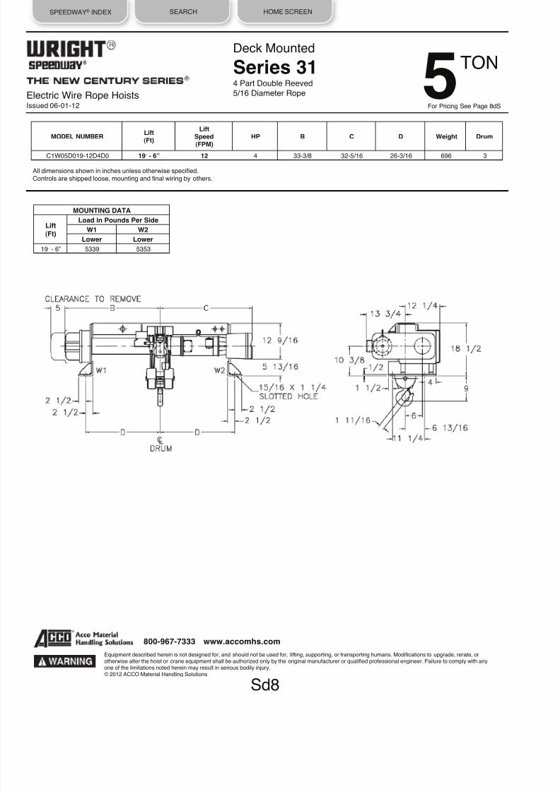
8/21/2019 2013 Wright Specifications Catalog
http://slidepdf.com/reader/full/2013-wright-specifications-catalog 40/189
SPEEDWAY® INDEX SEARCH HOME SCREEN
Electric Wire Rope HoistsIssued 06-01-12
Deck Mounted
Series 314 Part Double Reeved
5/16 Diameter Rope
All dimensions shown in inches unless otherwise specified.Controls are shipped loose, mounting and final wiring by others.
MODEL NUMBER
Lift
(Ft)
Lift
Speed(FPM) HP B C D Weight Drum
C1W05D019-12D4D0 19ʼ - 6” 12 4 33-3/8 32-5/16 26-3/16 696 3
MOUNTING DATA
Lift
(Ft)
Load in Pounds Per Side
W1 W2
Lower Lower
19ʼ - 6” 5339 5353
Sd8
Equipment described herein is not designed for, and should not be used for, lifting, supporting, or transporting humans. Modifications to upgrade, rerate, orotherwise alter the hoist or crane equipment shall be authorized only by the original manufacturer or qualified professional engineer. Failure to comply with anyone of the limitations noted herein may result in serious bodily injury.© 2012 ACCO Material Handling Solutions
800-967-7333 www.accomhs.com
TON 5For Pricing See Page 8dS

8/21/2019 2013 Wright Specifications Catalog
http://slidepdf.com/reader/full/2013-wright-specifications-catalog 41/189
SPEEDWAY® INDEX SEARCH HOME SCREEN
Electric Wire Rope HoistsIssued 06-01-12
Wright family of SPEEDWAY winches is a complete line of electric wire
rope hoists. It is an advanced design incorporating the most recentmaterials and concept. The most current duty cycle and safety
requirements of users are built into this line, not added on.
CONSTRUCTION FEATURES:
CONTROLS: Choose from single. 2-speed, or inverter. Controls are
magnetic reversing type, mechanically and electrically interlocked with
115 volt control circuit. All wiring conforms to applicable NEC
requirements. Motor thermostats are standard providing motor running
overcurrent protection. NEMA Type 3R enclosures are standard. Cover
is lightweight, tough ABS material, deep-drawn for maximum control
accessibility. Controls are shipped loose for customer mounting.
MOTOR: Standard NEMA C face mounting, TENV, Class F insulation,
30-minute duty motor is provided for standard commercial power
supplies. The motor has a standard NEMA shaft extension.
GEAR TRAIN: Quiet, helical and spur gearing. All gears are machine
cut, case-hardened alloy steel with shock-resistant ductile cores.
Gearing is designed to AGMA standards for maximum life, and
operates in an oil bath. Rugged aluminum alloy housing provides rapid
heat dissipation.
BEARINGS - SPIDER RETAINER: Precision heavy-duty ball bearings
support all shafts. Bearings at outboard end of shafts are held in place
by a heavy-duty Spider Retainer. This allows removal of Gear Housing
Cover for inspection (after draining oil). All internal parts remain in
place and can be operated for inspection.
DRUM: The large diameter steel drum has machined grooves and
large flanges. At least two full turns of rope remain on the drum at rated
drum winding capacity. Load capacity of each winch is rated a total linepull of the lead wire rope off the winch's drum. A single line winch has
one lead of wire rope off the drum rated at full capacity. A double line
winch has two leads of wire rope off hoist drum with a capacity of one
half hoist rated capacity.
MECHANICAL LOAD BRAKE: Automatic Weston-type multiple disc
brake. It can hold a full capacity load independent of the motor brake
and assures that load does not accelerate while being lowered.
Adjustment is not required.
MOTOR BRAKE: Proven in millions of hours of in-service operation,
the original Wright A-C magnet-actuated disc brake delivers rapid stops
with virtually no hook drift. Rated a minimum of 150% of full load motor
torque.
OVERLOAD CUTOFF: Exclusive patented Wright unit is not available
on winches.
HOW TO SPECIFY A SPEEDWAY WINCH
1. DETERMINE THE CAPACITY, NUMBER OF LINES, LIFTING
SPEED, AND WIRE ROPE LEAD OFF POSITION FOR YOUR
APPLICATION. SPEEDWAY winches may be reeved in various wa
to gain desired mechanical advantages. The chart in paragraph 4
illustrates characteristics of each type of reeving.
Reeving may change capacity, lifting distances, lifting speeds, and
cable size.
Reeving terminology is either "single" or "double" which refers to the
number of wire ropes coming from the drum.
Another word is "part" which refers to the mechanical advantage
gained by multiple reeving. For example, with one part single reevin
(1 PS), the load is supported by one part of a single rope. By reevin
single rope into two parts (2 part single) the load is distributed over
the two parts and the mechanical advantage doubles the capacity of
one part reeving and reduces by one half the lifting or lowering spee
of the hook.
2. SPECIFY PROPER MODEL NUMBER in regards to winch
capacity, drum winding capacity, lifting speed and hoist control found
in following pages. Winches are grouped by load capacity. All winch
are one part single reeved (1 PS) in either single or double line
models.
3. SPECIFY EITHER SINGLE LINE OR DOUBLE LINE MODEL.
4. SPECIFY DRUM REEVING ARRANGEMENTS.
Base Mounted WinchFeatures & Benefits
1/2 TO 1-1/2 TON
Equipment described herein is not designed for, and should not be used for, lift ing, supporting, or transporting humans. Modifications to upgrade, rerate, orotherwise alter the hoist or crane equipment shall be authorized only by the original manufacturer or qualified professional engineer. Failure to comply with anyone of the limitations noted herein may result in serious bodily injury.© 2012 ACCO Material Handling Solutions
800-967-7333 www.accomhs.com

8/21/2019 2013 Wright Specifications Catalog
http://slidepdf.com/reader/full/2013-wright-specifications-catalog 42/189
SPEEDWAY® INDEX SEARCH HOME SCREEN
Electric Wire Rope HoistsIssued 06-01-12
5. DETERMINE IF STANDARD LINE LEADOFF ANGLE ISAPPROPRIATE. SPEEDWAY winches are designed with a standard
range or ranges of leadoff angles. See the illustration below for location
of the standard range.
If any of desired leadoff angle falls into non standard area, the factory
must be consulted for fabrication and additional pricing factors, Specify
the desired angle range viewed from the gearing end of winch. State
angle in EXACT degree clockwise from zero vertical leadoff position as
shown. If a range of degrees is required, state both limits in degrees.
7. SPECIFY CABLE FITTINGS. The drum end (live end) cablefitting is attached to wire rope when supplied from the factory. The
cable fitting is designed for easy installation and is swaged on to
provide maximum security. See Accessories Section for pricing.
The following "DEAD END" cable fittings are available on
application:
• Eye Bolt • Turn Buckle • Threaded Rod • Swivel Hook
The "DEAD END" of wire rope may be specified "OPEN" (no
fittings) or with any of the above fittings.
8. SPECIFY LOAD BLOCK AND IDLER SHEAVES. Information
and data for these items are found in Accessories Section.
9. SPECIFY MOTOR VOLTAGE. Wright standard motors are
available in 200/230/460/575·3-60 power with Class F insulation,and are totally enclosed non-ventilated.
10. CONTROL. Control is furnished as standard equipment.
Additional motor and control accessories and modifications are
found in Accessories Section. Control is shipped loose for
customer mounting. If control mounting by ACCO is desired,
contact factory for pricing. Contact factory for control dimensions
and locations.
11. SPECIFY PUSH BUTTON STATION. Push button station,
drop of cord and strain chain are available as optional equipment.
Specify drop of push button, calculated from center line of a winch
to center line of the push button, See Accessories Section.
12. SPECIFY LIMIT SWITCHES. SPEEDWAY winches are not
furnished with a standard limit switch or an overload cutoff device.Geared limit switch is available as optional equipment. A separate
gravity limit switch to be actuated by the bottom block or load hook
assembly is required per ANSI / ASME B30 standards. Slack line
limit switch is available on application.
13. ACCO RESERVES THE RIGHT TO MAKE CHANGES TO
THIS CATALOG AS MAY BE DEEMED NECESSARY.
Base Mounted Winch
Features & Benefits
1/2 TO 1-1/2 TON
Equipment described herein is not designed for, and should not be used for, lifting, supporting, or transporting humans. Modifications to upgrade, rerate, orotherwise alter the hoist or crane equipment shall be authorized only by the original manufacturer or qualified professional engineer. Failure to comply with anyone of the limitations noted herein may result in serious bodily injury.© 2012 ACCO Material Handling Solutions
800-967-7333 www.accomhs.com
6. SPECIFY THE WIRE ROPE.
SPEEDWAY winches are not furnished with wire rope but are available
with wire rope as optional equipment. Wire rope on all winches is 6 x 37
preformed. Certain applications may require non-rotating cable, 18 x 7
construction. Prices for non-rotating cable are available on application.Specify the wire rope by total length, diameter, and desired fittings.

8/21/2019 2013 Wright Specifications Catalog
http://slidepdf.com/reader/full/2013-wright-specifications-catalog 43/189
SPEEDWAY® INDEX SEARCH HOME SCREEN
Base Mounted Winch
Series 311 Part Single Reeved
1/4 Diameter Rope
All dimensions shown in inches unless otherwise specified.Controls are shipped loose, mounting and final wiring by others at destination.(x) Maximum drum winding capacity is given with two remaining wraps of rope on drum.
MODEL NUMBERDrumWinding
Capacity (x)(Ft)
WireSpeed(FPM)
HP B C D Weight Drum
C1W92S052-30W1S0 52 30 1 16-3/8 15-3/8 9-3/16 339 1
C1W92S119-30W1S0 119 30 1 23-3/8 22-3/8 16-3/16 393 2
C1W92S215-30W1S0 215 30 1 33-3/8 32-3/8 26-3/16 473 3
C1W92S052-40W1S0 52 40 2 16-3/8 15-3/8 9-3/16 339 1
C1W92S119-40W1S0 119 40 2 23-3/8 22-3/8 16-3/16 393 2
C1W92S215-40W1S0 215 40 2 33-3/8 32-3/8 26-3/16 473 3
C1W92S052-60W1S0 52 60 2 16-3/8 15-3/8 9-3/16 339 1
C1W92S119-60W1S0 119 60 2 23-3/8 22-3/8 16-3/16 393 2
C1W92S215-60W1S0 215 60 2 33-3/8 32-3/8 26-3/16 473 3
C1W92S052-80W1S0 52 80 3 16-3/8 15-3/8 9-3/16 339 1
C1W92S119-80W1S0 119 80 3 23-3/8 22-3/8 16-3/16 393 2
C1W92S215-80W1S0 215 80 3 33-3/8 32-3/8 26-3/16 473 3
Sw1
Equipment described herein is not designed for, and should not be used for, lifting, supporting, or transporting humans. Modifications to upgrade, rerate, orotherwise alter the hoist or crane equipment shall be authorized only by the original manufacturer or qualified professional engineer. Failure to comply with anyone of the limitations noted herein may result in serious bodily injury.© 2012 ACCO Material Handling Solutions
800-967-7333 www.accomhs.com
TON
For Pricing See Page 1w
1
2
Electric Wire Rope HoistsIssued 06-01-12

8/21/2019 2013 Wright Specifications Catalog
http://slidepdf.com/reader/full/2013-wright-specifications-catalog 44/189
SPEEDWAY® INDEX SEARCH HOME SCREEN
Electric Wire Rope HoistsIssued 06-01-12
Base Mounted Winch
Series 311 Part Single Reeved
5/16 Diameter Rope
Sw2
Equipment described herein is not designed for, and should not be used for, lifting, supporting, or transporting humans. Modifications to upgrade, rerate, orotherwise alter the hoist or crane equipment shall be authorized only by the original manufacturer or qualified professional engineer. Failure to comply with anyone of the limitations noted herein may result in serious bodily injury.© 2012 ACCO Material Handling Solutions
All dimensions shown in inches unless otherwise specified.Controls are shipped loose, mounting and final wiring by others at destination.
(x) Maximum drum winding capacity is given with two remaining wraps of rope on drum.
800-967-7333 www.accomhs.com
TON 1For Pricing See Page 2wS
MODEL NUMBER
Drum
WindingCapacity (x)
(Ft)
WireSpeed(FPM)
HP B C D Weight Drum
C1W01S044-30W1S0 44 30 2 16-3/8 15-3/8 9-3/16 364 1
C1W01S100-30W1S0 100 30 2 23-3/8 22-3/8 16-3/16 418 2
C1W01S181-30W1S0 181 30 2 33-3/8 32-3/8 26-3/16 498 3
C1W01S044-40W1S0 44 40 3 16-3/8 15-3/8 9-3/16 364 1
C1W01S100-40W1S0 100 40 3 23-3/8 22-3/8 16-3/16 418 2
C1W01S181-40W1S0 181 40 3 33-3/8 32-3/8 26-3/16 498 3
C1W01S044-60W1S0 44 60 4 16-3/8 15-3/8 9-3/16 364 1
C1W01S100-60W1S0 100 60 4 23-3/8 22-3/8 16-3/16 418 2
C1W01S181-60W1S0 181 60 4 33-3/8 32-3/8 26·3/16 498 3

8/21/2019 2013 Wright Specifications Catalog
http://slidepdf.com/reader/full/2013-wright-specifications-catalog 45/189
SPEEDWAY® INDEX SEARCH HOME SCREEN
Electric Wire Rope HoistsIssued 06-01-12
Base Mounted Winch
Series 311 Part Double Reeved3/16 Diameter Rope
All dimensions shown in inches unless otherwise specified.Controls are shipped loose, mounting and final wiring by others at destination.(x) Maximum drum winding capacity, each hand, is given with two remaining wraps of rope on drum.
Sw3
Equipment described herein is not designed for, and should not be used for, lifting, supporting, or transporting humans. Modifications to upgrade, rerate, orotherwise alter the hoist or crane equipment shall be authorized only by the original manufacturer or qualified professional engineer. Failure to comply with any
one of the limitations noted herein may result in serious bodily injury.© 2012 ACCO Material Handling Solutions
800-967-7333 www.accomhs.com
TON
For Pricing See Page 3w
1
2
MODEL NUMBER
Drum
WindingCapacity (x)
(Ft)
WireSpeed(FPM)
HP B C D Weight Drum
C1W92D064-30W1D0 64 30 1 23-3/8 22-3/8 16-3/16 393 2
C1W92D123-30W1D0 123 30 1 33-3/8 32-3/8 26-3/16 473 3
C1W92D064-40W1D0 64 40 2 23-3/8 22-3/8 16-3/16 393 2
C1W92D123-40W1D0 123 40 2 33-3/8 32-3/8 26-3/16 473 3
C1W92D064-60W1D0 64 60 2 23-3/8 22-3/8 16-3/16 393 2
C1W92D123-60W1D0 123 60 2 33-3/8 32-3/8 26-3/16 473 3
C1W92D064-80W1D0 64 80 3 23-3/8 22-3/8 16-3/16 393 2
C1W92D123-80W1D0 123 80 3 33-3/8 32-3/8 26-3/16 473 3

8/21/2019 2013 Wright Specifications Catalog
http://slidepdf.com/reader/full/2013-wright-specifications-catalog 46/189
SPEEDWAY® INDEX SEARCH HOME SCREEN
Electric Wire Rope HoistsIssued 06-01-12
Base Mounted Winch
Series 311 Part Double Reeved
1/4 Diameter Rope
All dimensions shown in inches unless otherwise specified.Controls are shipped loose, mounting and final wiring by others at destination.(x) Maximum drum winding capacity, each hand, is given with two remaining wraps of rope on drum.
Sw4
Equipment described herein is not designed for, and should not be used for, lifting, supporting, or transporting humans. Modifications to upgrade, rerate, orotherwise alter the hoist or crane equipment shall be authorized only by the original manufacturer or qualified professional engineer. Failure to comply with anyone of the limitations noted herein may result in serious bodily injury.© 2012 ACCO Material Handling Solutions
800-967-7333 www.accomhs.com
MODEL NUMBER
Drum
WindingCapacity (x)(Ft)
Wire
Speed(FPM)
HP B C D Weight Drum
C1W01D051-30W1D0 51 30 2 23-3/8 22-3/8 16-3/16 418 2
C1W01D099-30W1D0 99 30 2 33-3/8 32-3/8 26-3/16 498 3
C1W01D051-40W1D0 51 40 3 23-3/8 22-3/8 16-3/16 418 2
C1W01D099-40W1D0 99 40 3 33-3/8 32-3/8 26-3/16 498 3
C1W01D051-60W1D0 51 60 4 23-3/8 22-3/8 16-3/16 418 2
C1W01D099-60W1D0 99 60 4 33-3/8 32-3/8 26-3/16 498 3
TON 1For Pricing See Page 4wS

8/21/2019 2013 Wright Specifications Catalog
http://slidepdf.com/reader/full/2013-wright-specifications-catalog 47/189
SPEEDWAY® INDEX SEARCH HOME SCREEN
Electric Wire Rope HoistsIssued 06-01-12
Base Mounted Winch
Series 311 Part Double Reeved5/16 Diameter Rope
All dimensions shown in inches unless otherwise specified.Controls are shipped loose, mounting and final wiring by others at destination.(x) Maximum drum winding capacity, each hand, is given with two remaining wraps of rope on drum.
Sw5
Equipment described herein is not designed for, and should not be used for, lifting, supporting, or transporting humans. Modifications to upgrade, rerate, orotherwise alter the hoist or crane equipment shall be authorized only by the original manufacturer or qualified professional engineer. Failure to comply with anyone of the limitations noted herein may result in serious bodily injury.© 2012 ACCO Material Handling Solutions
800-967-7333 www.accomhs.com
MODEL NUMBER
Drum
WindingCapacity (x)
(Ft)
WireSpeed(FPM)
HP B C D Weight Drum
C1W96D042-30W1D0 42 30 3 23-3/8 22-3/8 16-3/16 449 2
C1W96D083-30W1D0 83 30 3 33-3/8 32-3/8 26-3/16 529 3
C1W96D042-40W1D0 42 40 4 23-3/8 22-3/8 16-3/16 449 2
C1W96D083-40W1D0 83 40 4 33-3/8 32-3/8 26-3/16 529 3
TON1For Pricing See Page 5w
1
2

8/21/2019 2013 Wright Specifications Catalog
http://slidepdf.com/reader/full/2013-wright-specifications-catalog 48/189
WORK-RATED® INDEX SEARCH HOME SCREEN
Electric Wire Rope HoistsIssued 06-01-12
Wright family of Work-Rated hoists is a complete line of electric wire rope
hoists. It is an advanced design incorporating the most recent materials andconcept. The most current duty cycle and safety requirements of users arebuilt into this line, not added on.
CONSTRUCTION FEATURES:
CONTROLS: Choose from single, 2-speed, or inverter. Controls are magnetic
reversing type, mechanically and electrically interlocked with 115 volt controlcircuit. All wiring conforms to applicable NEC requirements. Motor thermostats
are standard providing motor running overcurrent protection. NEMA Type 3Renclosures are standard. Cover is lightweight, tough ABS material, deep-
drawn for maximum control accessibility.
PUSH BUTTON STATION: Push button stations are not furnished asstandard equipment with these hoists. Push button station drop of cord &
strain chain are available as optional equipment. See Accessories Section.Specify required drop.
MOTOR: Standard NEMA C face mounting, TENV, Class F insulation, 30-
minute duty motor is provided for standard commercial power supplies. The
motor has a standard NEMA shaft extension.
GEAR TRAIN: Quiet, helical and spur gearing. All gears are machine cut,
case-hardened alloy steel with shock-resistant ductile cores. Gearing isdesigned to AGMA standards for maximum life, and operates in an oil bath.
Rugged aluminum alloy housing provides rapid heat dissipation.
BEARINGS - SPIDER RETAINERS: Precision heavy-duty ball bearingssupport all shafts. All bearings are either splash lubricated, or lifetime
pre-lubricated and sealed. Bearings at outboard end of shafts are held inplace by heavy-duty Spider Retainers. This allows removal of Gear Housing
Cover for inspection (after draining oil). All internal parts remain in place andcan be operated for inspection.
DRUM: The large diameter steel drum has machined grooves and largeflanges. At least two full turns of rope remain on the drum at the lowest hookposition of rated lift.
LOAD BLOCK - HOOK: Drop forged heat-treated steel hook swivels 360˚ on
a shielded roller thrust bearing and comes equipped with a spring latch. Workcan be performed on the load block without removing wire rope from drum.
Sheaves are machined steel.
WIRE ROPE: Pre-formed wire rope, of hoisting service construction, made of
extra improved plow steel (XIP) with an independent wire rope center. Hasswaged fittings on both ends for ease of replacement if necessary.
MECHANICAL LOAD BRAKE: Automatic Weston-type multiple disc brakecan hold a full capacity load independent of motor brake. This brake assures
that load does not accelerate while being lowered. No wear compensationadjustment is required.
MOTOR BRAKE: Proven in millions of hours of in-service operation, the
original Wright rectified D-C magnet-actuated disc brake delivers rapid stopswith virtually no hook drift. Rated a minimum of 150% of full load motor torque.
Exclusive brake-sensing microswitch prevents motor from operating againstengaged brake and when brake requires adjustment.
LIMIT SWITCH: A gravity-type upper hook travel limit switch is provided.
The unit is equipped with an automatic momentary lowering circuit. Anoptional geared limit switch is also available.
OVERLOAD CUTOFF: Exclusive patented ACCO unit is standard on allWork-Rated hoists except single-line models. The overload limiting devic
shall be designed to permit operation of the hoist within its rated load andlimit the amount of overload that can be lifted by a properly maintained
hoist, under normal operating conditions.
The overload limiting device may allow the lifting of an overload, but shalbe designed to prevent the lifting of an overload of such magnitude that
could cause damage to a hoist, trolley, or supports. This does not imply tany overload is to be intentionally applied to the hoist.
The overload limiting device is an emergency device and shall not be use
to measure the maximum load to be lifted and shall not be used to sensethe overload imposed by the constrained load.
TROLLEY FRAME: The trolley frame shall be built of steel and precision
machined to assure proper alignment of trolley wheels and drives.
TROLLEY WHEELS: Trolley wheels shall have tread surfaces machinedand hardened to 375-425 Brinell. Each wheel shall be supported on anti-
friction bearings suitable to take radial and thrust loads. The wheels shal
be lubricated at the factory with a sodium base grease. The trolley wheelhave dual tread for operation on tapered or flat flange beams. Wheel trea
shall be smooth, true and uniform within .010 inch tread diameter on allwheels.
TROLLEY DRIVE: The trolley drive shall be a right angle worm gear
reducer fully enclosed with a steel worm and bronze worm wheel designeto AGMA standards. The final reduction gear reduction at trolley wheels
be spur gears and will be open. The trolley drive motor shall be TENV 30minute duty with class F insulation and NEMA C face mounting. A spring
set A.C. disc type brake is available as optional equipment.
TROLLEY CONTROLS: Choose from single, 2-speed, or inverter. Singleand 2-speed control are available with ACM solid state cushion start for
smooth travel motion and excellent load control as optional equipment.
HOW TO SPECIFY A Work-Rated HOIST
1. DETERMINE THE CAPACITY, LIFTING SPEED AND LIFTING
DISTANCE.
2. DETERMINE THE REEVING REQUIRED FOR YOUR
APPLICATION. Work-Rated hoists may be reeved in various ways to ga
desired mechanical advantages ... capacity, lifting distance, and lifting
speeds.
Reeving terminology is either "single" or "double" which refers to the
number of wire ropes coming from the drum.
Monorail HoistFeatures & Benefits 1TO 25 TON
Equipment described herein is not designed for, and should not be used for, lifting, supporting, or transporting humans. Modifications to upgrade, rerate, orotherwise alter the hoist or crane equipment shall be authorized only by the original manufacturer or qualified professional engineer. Failure to comply with anyone of the limitations noted herein may result in serious bodily injury.© 2012 ACCO Material Handling Solutions
800-967-7333 www.accomhs.com

8/21/2019 2013 Wright Specifications Catalog
http://slidepdf.com/reader/full/2013-wright-specifications-catalog 49/189
WORK-RATED® INDEX SEARCH HOME SCREEN
Electric Wire Rope HoistsIssued 06-01-12
Another word is "part" which refers to the mechanical advantage gained by
multiple reeving. For example, with 2 part single reeving (2 PS) the load isdistributed over the two parts and the mechanical advantage doubles the
capacity of one part reeving and reduces by one half the lifting or loweringspeed of the hook.
Reeving changes hoist arrangement to the beam or t rack, minimum
headroom distance, and lateral hook travel.
Monorail HoistFeatures & Benefits 1TO 25 TON
Some applications require that the load, when being lif ted, not move right or
left from hoist centerline. If this requirement is known, a true vertical lift hoistmust be used. These are described as two part double (2 PD) or four part
double (4 PD).
Single Reeved
Double Reeved
Reeving:
2 PS or 4 PS
2 PD or 4 PD
Minimum
Fair
Good
Headroom:
Lateral Hook travels None
Hook Travel:
Cost:
Lower
Higher
Equipment described herein is not designed for, and should not be used for, lifting, supporting, or transporting humans. Modifications to upgrade, rerate, orotherwise alter the hoist or crane equipment shall be authorized only by the original manufacturer or qualified professional engineer. Failure to comply with anyone of the limitations noted herein may result in serious bodily injury.© 2012 ACCO Material Handling Solutions
800-967-7333 www.accomhs.com
HEADROOM: Some applications require that the distance from the
bottom of beam to saddle of the hook be held to a minimum. Thisdimension will determine whether single reeved or double reeved modelis required.
3. SPECIFY PROPER MODEL NUMBER in regard to hoist.
Capacity, lifting speed, mounting and hoist control found in thefollowing pages.
4. SPECIFY MOTOR VOLTAGE: Wright standard motors are
available in 200/230/460/575-3-60 power with Class F insulation,and are totally enclosed non-ventilated. Control is furnished as
standard equipment. Additional motor and control accessories arefound in the Accessories Section.
5. SPECIFY BEAM FLANGE WIDTH: Work-rated trolleys are
adjustable for Standard I beam or WF beam, 4 inch to 11 inchflange width. Beam size must be specified. Trolleys are also
available for 3.25 or 3.33" patented track beams. Trolleys for WFbeams with flange widths greater than 11 inches available. SeeAccessories. All reference to beam flange widths are for clearance
purposes only and do not imply that lower flange of beam will supporthoist with load.
6. SPECIFY OTHER MODIFICATIONS AND ACCESSORIES.
7. SPECIAL APPLICATION HOISTS: Contact your nearest Wright
representative.
8. FOR CURVED TRACK APPLICATION, CONTACT FACTORY.
9. ACCO RESERVES THE RIGHT TO MAKE CHANGES TO
THIS CATALOG AS MAY BE DEEMED NECESSARY.

8/21/2019 2013 Wright Specifications Catalog
http://slidepdf.com/reader/full/2013-wright-specifications-catalog 50/189
WORK-RATED® INDEX SEARCH HOME SCREEN
Monorail Hoist
Series 322 Part Single Reeved
3/8 Diameter Rope
Equipment described herein is not designed for, and should not be used for, lifting, supporting, or transporting humans. Modifications to upgrade, rerate, orotherwise alter the hoist or crane equipment shall be authorized only by the original manufacturer or qualified professional engineer. Failure to comply with anyone of the limitations noted herein may result in serious bodily injury.
© 2012 ACCO Material Handling Solutions
m1
1
*To complete Model Number insert L, P, G or M in place of asterick.All dimensions shown in inches unless otherwise specified. Dimensions which change with beam size are for minimum beam shown.
Work-Rated trolleys are adjustable for Standard I beam or WF beam, 4 inch to 11 inch flange width. Beam size must be specified. Trolleys are also available for3.25 or 3.33" patented track beams. See Accessories Section for applications with flange width exceeding 11 inches.All reference to beam flange widths are for clearance purposes only and do not imply that lower flange of beam will support hoist with load.
TROLLEY DATA: SPEED 50 FPM 100 FPM
HP 1/2 1/2
All two speed trolley motors are 1800/600 RPM.
(a) Trolley Brake is available as optional equipment
TON For Pricing See Page 1m
Electric Wire Rope HoistsIssued 06-01-12
MODEL NUMBERLift
(Ft)
Lift
Speed(FPM)
HP B CHook Travel
T1 T2 DrumL U
C2W01S020-15*2S0 20 15 3 15-3/4 17-1/4 1-15/16 3-5/16 - - 1
C2W01S036-15*2S0 36 15 3 19-3/8 21-1/8 1-13/16 7-3/16 7-1/8 7-7/8 3
C2W01S054-15*2S0 54 15 3 23-3/4 25-1/2 1-13/16 11-9/16 11-1/2 12-1/4 4
C2W01S086-15*2S0 86 15 3 31-1/4 33 1-13/16 19-1/16 19 19-3/4 6
C2W01S020-22*2S0 20 22 3 15-3/4 17-1/4 1-15/16 3-5/16 - - 1
C2W01S036-22*2S0 36 22 3 19-3/8 21-1/8 1-13/16 7-3/16 7-1/8 7-7/8 3
C2W01S054-22*2S0 54 22 3 23-3/4 25-1/2 1-13/16 11-9/16 11-1/2 12-1/4 4
C2W01S086-22*2S0 86 22 3 31-1/4 33 1-13/16 19-1/16 19 19-3/4 6
C2W01S020-30*2S0 20 30 3 15-3/4 17-1/4 1-15/16 3-5/16 - -
1
C2W01S036-30*2S0 36 30 3 19-3/8 21-1/8 1-13/16 7-3/16 7-1/8 7-7/8 3
C2W01S054-30*2S0 54 30 3 23-3/4 25-1/2 1-13/16 11-9/16 11-1/2 12-1/4 4
C2W01S086-30*2S0 86 30 3 31-1/4 33 1-13/16 19-1/16 19 19-3/4 6
LUG MOUNTED Lift
(Ft) Weight Pin Load in Lbs. (Max) P1 P2
20 578 2332 1558 36 624 711 2401 54 677 676 2452 86 769 667 2514
PLAIN OR GEARED TROLLEY Lift(Ft) Weight* Wheel Load in Lbs. (Max)
PR.W1 PR.W2 20 738 2203 1584 36 752 1469 1241 54 805 1399 1267 86 897 1381 1298
MOTORIZED TROLLEY Lift
(Ft) Weight Wheel Load in Lbs. (Max) PR.W1 PR.W2
20 806 2220 1601 36 820 1469 1275 54 873 1399 1301 86 965 1381 1332

8/21/2019 2013 Wright Specifications Catalog
http://slidepdf.com/reader/full/2013-wright-specifications-catalog 51/189
WORK-RATED® INDEX SEARCH HOME SCREEN
* Add 40 Lbs. for Geared Trolley.
LUG MOUNTED Lift
(Ft) Weight Pin Load in Lbs. (Max) P1 P2
20 905 1946 2318
43 996 728 2638
66 1097 723 2713
93 1214 767 2775
135 1396 813 2869
188 1625 891 2966
Monorail Hoist
Series 332 Part Single Reeved
1/2 Diameter Rope
*To complete Model Number insert L, P, G or M in place of asterick.All dimensions shown in inches unless otherwise specified. Dimensions which change with beam size are for minimum beam shown.Work-Rated trolleys are adjustable for Standard I beam or WF beam, 4 inch to 11 inch flange width. Beam size must be specified. Trolleys are also available for3.25 or 3.33" patented track beams. See Accessories Section for applications with flange width exceeding 11 inches.All reference to beam flange widths are for clearance purposes only and do not imply that lower flange of beam will support hoist with load.
TROLLEY DATA: SPEED 50 FPM 100 FPM
HP1/2 1/2
MOTORIZED TROLLEY Lift
(Ft) Weight Wheel Load in Lbs. (Max) PR.W1 PR.W2
20 1133 2050 2432
43 1255 1514 1420
66 1356 1504 1457
93 1473 1592 1488
135 1655 1684 1535
188 1884 1840 1584
PLAIN OR GEARED TROLLEY Lift(Ft) Weight* Wheel Load in Lbs. (Max)
PR.W1 PR.W2 20 1065 2026 2398
43 1187 1514 1386
66 1288 1504 1423
93 1405 1592 1454
135 1587 1684 1501
188 1816 1840 1550
Equipment described herein is not designed for, and should not be used for, lifting, supporting, or transporting humans. Modifications to upgrade, rerate, orotherwise alter the hoist or crane equipment shall be authorized only by the original manufacturer or qualified professional engineer. Failure to comply with any
one of the limitations noted herein may result in serious bodily injury.© 2012 ACCO Material Handling Solutions
m2
800-967-7333 www.accomhs.com
MODEL NUMBERLift
(Ft)
Lift
Speed(FPM)
HP B CHook Travel
T1 T2 DrumL U
C3W01S020-44*2S0 20 44 7-1/2 18-7/16 18-1/4 1-11/16 3-3/4 - - 1
C3W01S043-44*2S0 43 44 7-1/2 21-1/2 23-1/4 2-1/16 8-3/8 9-1/4 9-3/4 2
C3W01S066-44*2S0 66 44 7-1/2 27 28-3/4 2-1/16 13-7/8 14-3/4 15-1/4 3
C3W01S093-44*2S0 93 44 7-1/2 33-1/2 35-1/4 2-1/16 20-3/8 19-1/4 21-3/4 4
C3W01S135-44*2S0 135 44 7-1/2 43-1/2 45-1/4 2-1/16 30-3/8 27-1/4 31-3/4 5
C3W01S188-44*2S0 188 44 7-1/2 56 57-3/4 2-1/16 42-7/8 35-3/4 44-1/4 6
TON 1For Pricing See Page 1m
All two speed trolley motors are 1800/600 RPM.
(a) Trolley Brake is available as optional equipment
Electric Wire Rope HoistsIssued 06-01-12

8/21/2019 2013 Wright Specifications Catalog
http://slidepdf.com/reader/full/2013-wright-specifications-catalog 52/189
WORK-RATED® INDEX SEARCH HOME SCREEN
* Add 40 Lbs. for Geared Trolley.
Electric Wire Rope HoistsIssued 06-01-12
Monorail Hoist
Series 322 Part Single Reeved
3/8 Diameter Rope
LUG MOUNTED Lift
(Ft) Weight Pin Load in Lbs. (Max) P1 P2
20 578 4160 3043 36 624 1357 4310 54 677 1268 4394 86 769 1223 4478
PLAIN OR GEARED TROLLEY Lift(Ft) Weight* Wheel Load in Lbs. (Max)
PR.W1 PR.W2 20 738 3866 2972 36 752 2761 2196 54 805 2583 2237 86 897 2493 2280
MOTORIZED TROLLEY Lift(Ft) Weight Wheel Load in Lbs. (Max)
PR.W1 PR.W2 20 806 3883 2989 36 820 2761 2230 54 873 2583 2271 86 965 2493 2314
*To complete Model Number insert L, P, G or M in place of asterick.All dimensions shown in inches unless otherwise specified. Dimensions which change with beam size are for minimum beam shown.Work-Rated trolleys are adjustable for Standard I beam or WF beam, 4 inch to 11 inch flange width. Beam size must be specified. Trolleys are also available for3.25 or 3.33" patented track beams. See Accessories Section for applications with flange width exceeding 11 inches.All reference to beam flange widths are for clearance purposes only and do not imply that lower flange of beam will support hoist with load.
TROLLEY DATA: SPEED 50 FPM 100 FPM
HP 1/2 1/2
All two speed trolley motors are 1800/600 RPM.(a) Trolley Brake is available as optional equipment
Equipment described herein is not designed for, and should not be used for, lifting, supporting, or transporting humans. Modifications to upgrade, rerate, orotherwise alter the hoist or crane equipment shall be authorized only by the original manufacturer or qualified professional engineer. Failure to comply with anyone of the limitations noted herein may result in serious bodily injury.© 2012 ACCO Material Handling Solutions
m3
800-967-7333 www.accomhs.com
MODEL NUMBER
Lift
(Ft)
Lift
Speed(FPM)
HP B C
Hook Travel
T1 T2 DrumL U
C2W02S020-15*2S0 20 15 3 15-3/4 17-1/4 1-15/16 3-5/16 - - 1
C2W02S036-15*2S0 36 15 3 19-3/8 21-1/8 1-13/16 7-3/16 7-1/8 7-7/8 3
C2W02S054-15*2S0 54 15 3 23-3/4 25-1/2 1-13/16 11-9/16 11-1/2 12-1/4 4
C2W02S086-15*2S0 86 15 3 31-1/4 33 1-13/16 19-1/16 19 19-3/4 6
C2W02S020-22*2S0 20 22 3 15-3/4 17-1/4 1-15/16 3-5/16 - - 1
C2W02S036-22*2S0 36 22 3 19-3/8 21-1/8 1-13/16 7-3/16 7-1/8 7-7/8 3
C2W02S054-22*2S0 54 22 3 23-3/4 25-1/2 1-13/16 11-9/16 11-1/2 12-1/4 4
C2W02S086-22*2S0 86 22 3 31-1/4 33 1-13/16 19-1/16 19 19-3/4 6
C2W02S020-30*2S0 20 30 5 15-3/4 17-1/4 1-15/16 3-5/16 - - 1
C2W02S036-30*2S0 36 30 5 19-3/8 21-1/8 1-13/16 7-3/16 7-1/8 7-7/8 3
C2W02S054-30*2S0 54 30 5 23-3/4 25-1/2 1-13/16 11-9/16 11-1/2 12-1/4 4
C2W02S086-30*2S0 86 30 5 31-1/4 33 1-13/16 19-1/16 19 19-3/4 6
TON2For Pricing See Page 2m

8/21/2019 2013 Wright Specifications Catalog
http://slidepdf.com/reader/full/2013-wright-specifications-catalog 53/189
WORK-RATED® INDEX SEARCH HOME SCREEN
* Add 40 Lbs. for Geared Trolley.
Equipment described herein is not designed for, and should not be used for, lifting, supporting, or transporting humans. Modifications to upgrade, rerate, orotherwise alter the hoist or crane equipment shall be authorized only by the original manufacturer or qualified professional engineer. Failure to comply with anyone of the limitations noted herein may result in serious bodily injury.© 2012 ACCO Material Handling Solutions
LUG MOUNTED Lift(Ft) Weight Pin Load in Lbs. (Max)
P1 P2 20 905 3681 3943
43 996 1349 4494
66 1097 1300 4621
93 1214 1348 4708
135 1396 1386 4822
188 1625 1470 4932
Monorail Hoist
Series 332 Part Single Reeved
1/2 Diameter Rope
Electric Wire Rope HoistsIssued 06-01-12
m4
MOTORIZED TROLLEY Lift
(Ft) Weight Wheel Load in Lbs. (Max) PR.W1 PR.W2
20 1133 3795 4057
43 1255 2756 234866 1356 2658 2412
93 1473 2754 2455
135 1655 2830 2512
188 1884 2998 2567
PLAIN OR GEARED TROLLEY Lift
(Ft) Weight* Wheel Load in Lbs. (Max) PR.W1 PR.W2
20 1065 3761 4023
43 1187 2756 2314
66 1288 2658 2378
93 1405 2754 2421
135 1587 2830 2478
188 1816 2998 2533
800-967-7333 www.accomhs.com
*To complete Model Number insert L, P, G or M in place of asterick.All dimensions shown in inches unless otherwise specified. Dimensions which change with beam size are for minimum beam shown.
Work-Rated trolleys are adjustable for Standard I beam or WF beam, 4 inch to 11 inch flange width. Beam size must be specified. Trolleys are also available for3.25 or 3.33" patented track beams. See Accessories Section for applications with flange width exceeding 11 inches.All reference to beam flange widths are for clearance purposes only and do not imply that lower flange of beam will support hoist with load.
TROLLEY DATA: SPEED 50 FPM 100 FPM
HP 1/2 1/2
MODEL NUMBER Lift(Ft)
Lift
Speed(FPM)
HP B C Hook Travel
T1 T2 Drum
L U
C3W02S020-44*2S0 20 44 7-1/2 18-7/16 18-1/4 1-11/16 3-3/4 -
-
1
C3W02S043-44*2S0 43 44 7-1/2 21-1/2 23-1/4 2-1/16 8-3/8 9-1/4 9-3/4 2
C3W02S066-44*2S0 66 44 7-1/2 27 28-3/4 2-1/16 13-7/8 14-3/4 15-1/4 3
C3W02S093-44*2S0 93 44 7-1/2 33-1/2 35-1/4 2-1/16 20-3/8 19-1/4 21-3/4 4
C3W02S135-44*2S0 135 44 7-1/2 43-1/2 45-1/4 2-1/16 30-3/8 27-1/4 31-3/4 5
C3W02S188-44*2S0 188 44 7-1/2 56 57-3/4 2-1/16 42-7/8 35-3/4 44-1/4 6
TON 2For Pricing See Page 2m
All two speed trolley motors are 1800/600 RPM.
(a) Trolley Brake is available as optional equipment

8/21/2019 2013 Wright Specifications Catalog
http://slidepdf.com/reader/full/2013-wright-specifications-catalog 54/189
WORK-RATED® INDEX SEARCH HOME SCREEN
* Add 40 Lbs. for Geared Trolley.
Monorail Hoist
Series 322 Part Single Reeved
3/8 Diameter Rope
All two speed trolley motors are 1800/600 RPM.
(a) Trolley Brake is available as optional equipment
LUG MOUNTED Lift
(Ft) Weight Pin Load in Lbs. (Max) P1 P2
20 578 5988 4527
36 624 2003 6218
54 677 1860 6336
86 769 1780 6443
PLAIN OR GEARED TROLLEY Lift
(Ft) Weight* Wheel Load in Lbs. (Max) PR.W1 PR.W2
20 738 5488 4319
36 752 4053 3150
54 805 3767 3209
86 897 3607 3262
MOTORIZED TROLLEY Lift
(Ft) Weight Wheel Load in Lbs. (Max) PR.W1 PR.W2
20 806 5505 4336
36 820 4053 3184
54 873 3767 3243
86 965 3607 3296
Equipment described herein is not designed for, and should not be used for, lifting, supporting, or transporting humans. Modifications to upgrade, rerate, orotherwise alter the hoist or crane equipment shall be authorized only by the original manufacturer or qualified professional engineer. Failure to comply with any
one of the limitations noted herein may result in serious bodily injury.© 2012 ACCO Material Handling Solutions
m5
800-967-7333 www.accomhs.com
*To complete Model Number insert L, P, G or M in place of asterick.All dimensions shown in inches unless otherwise specified. Dimensions which change with beam size are for minimum beam shown.
Work-Rated trolleys are adjustable for Standard I beam or WF beam, 4 inch to 11 inch flange width. Beam size must be specified. Trolleys are also available for3.25 or 3.33" patented track beams. See Accessories Section for applications with flange width exceeding 11 inches.All reference to beam flange widths are for clearance purposes only and do not imply that lower flange of beam will support hoist with load.
TROLLEY DATA: SPEED 50 FPM 100 FPM
HP 1/2 1/2
MODEL NUMBER
Lift
(Ft)
Lift
Speed(FPM)
HP B C
Hook Travel
T1 T2 DrumL U
C2W03S020-15*2S0 20 15 3 15-3/4 17-1/4 1-15/16 3-5/16 - - 1
C2W03S036-15*2S0 36 15 3 19-3/8 21-1/8 1-13/16 7-3/16 7-1/8 7-7/8 3
C2W03S054-15*2S0 54 15 3 23-3/4 25-1/2 1-13/16 11-9/16 11-1/2 12-1/4 4
C2W03S086-15*2S0 86 15 3 31-1/4 33 1-13/16 19-1/16 19 19-3/4 6
C2W03S020-22*2S0 20 22 5 15-3/4 17-1/4 1-15/16 3-5/16 - - 1
C2W03S036-22*2S0 36 22 5 19-3/8 21-1/8 1-13/16 7-3/16 7-1/8 7-7/8 3
C2W03S054-22*2S0 54 22 5 23-3/4 25-1/2 1-13/16 11-9/16 11-1/2 12-1/4 4
C2W03S086-22*2S0 86 22 5 31-1/4 33 1-13/16 19-1/16 19 19-3/4 6
TON3For Pricing See Page 3m
Electric Wire Rope HoistsIssued 06-01-12

8/21/2019 2013 Wright Specifications Catalog
http://slidepdf.com/reader/full/2013-wright-specifications-catalog 55/189
WORK-RATED® INDEX SEARCH HOME SCREEN
* Add 40 Lbs. for Geared Trolley.
Electric Wire Rope HoistsIssued 06-01-12
Monorail Hoist
Series 332 Part Single Reeved
1/2 Diameter Rope
LUG MOUNTED Lift(Ft) Weight Pin Load in Lbs. (Max)
P1 P2 20 905 5418 5565
43 996 1962 6349
66 1097 1878 6530
93 1214 1925 6640
135 1396 1957 6775
188 1625 2049 6897
PLAIN OR GEARED TROLLEY Lift
(Ft) Weight* Wheel Load in Lbs. (Max) PR.W1 PR.W2
20 1065 5498 5645
43 1187 3982 3241
66 1288 3814 3332
93 1405 3908 3387
135 1587 3972 3454
188 1816 4156 3515
MOTORIZED TROLLEY Lift(Ft) Weight Wheel Load in Lbs. (Max) PR.W1 PR.W2
20 1133 5532 5679
43 1255 3982 3275
66 1356 3814 3366
93 1473 3908 3421
135 1655 3972 3488
188 1884 4156 3549
Equipment described herein is not designed for, and should not be used for, lift ing, supporting, or transporting humans. Modifications to upgrade, rerate, orotherwise alter the hoist or crane equipment shall be authorized only by the original manufacturer or qualified professional engineer. Failure to comply with anyone of the limitations noted herein may result in serious bodily injury.© 2012 ACCO Material Handling Solutions
m6
800-967-7333 www.accomhs.com
MODEL NUMBER
Lift
(Ft)
Lift
Speed(FPM) HP B C
Hook Travel
T1 T2 DrumL U
C3W03S020-30*2S0 20 30 7-1/2 18-7/16 18-1/4 1-11/16 3-3/4 - - 1
C3W03S043-30*2S0 43 30 7-1/2 21-1/2 23-1/4 2-1/16 8-3/8 9-1/4 9-3/4 2
C3W03S066-30*2S0 66 30 7-1/2 27 28-3/4 2-1/16 13-7/8 14-3/4 15-1/4 3
C3W03S093-30*2S0 93 30 7-1/2 33-1/2 35-1/4 2-1/16 20-3/8 19-1/4 21-3/4 4
C3W03S135-30*2S0 135 30 7-1/2 43-1/2 45-1/4 2-1/16 30-3/8 27-1/4 31-3/4 5
C3W035188-30*2S0 188 30 7-1/2 56 57-3/4 2-1/16 42-7/8 35-3/4 44-1/4 6
C3W03S020-44*2S0 20 44 10 18-7/16 18-1/4 1-11/16 3-3/4 - - 1
C3W03S043-44*2S0 43 44 10 21-1/2 23-1/4 2-1/16 8-3/8 9-1/4 9-3/4 2
C3W03S066-44*2S0 66 44 10 27 28-3/4 2-1/16 13-7/8 14-3/4 15-1/4 3
C3W03S093-44*2S0 93 44 10 33-1/2 35-1/4 2-1/16 20-3/8 19-1/4 21-3/4 4
C3W03S135-44*2S0 135 44 10 43-1/2 45-1/4 2-1/16 30-3/8 27-1/4 31-3/4 5
C3W035188-44*2S0 188 44 10 56 57-3/4 2-1/16 42-7/8 35-3/4 44-1/4 6
*To complete Model Number insert L, P, G or M in place of asterick.
All dimensions shown in inches unless otherwise specified. Dimensions which change with beam size are for minimum beam shown.Work-Rated trolleys are adjustable for Standard I beam or WF beam, 4 inch to 11 inch flange width. Beam size must be specified. Trolleys are also available for3.25 or 3.33" patented track beams. See Accessories Section for applications with flange width exceeding 11 inches.
All reference to beam flange widths are for clearance purposes only and do not imply that lower flange of beam will support hoist with load.
TROLLEY DATA: SPEED 50 FPM 100 FPMHP 1/2 1/2
All two speed trolley motors are 1800/600 RPM.(a) Trolley Brake is available as optional equipment
TON 3For Pricing See Page 3m

8/21/2019 2013 Wright Specifications Catalog
http://slidepdf.com/reader/full/2013-wright-specifications-catalog 56/189
WORK-RATED® INDEX SEARCH HOME SCREEN
* Add 40 Lbs. for Geared Trolley.
Electric Wire Rope HoistsIssued 06-01-12
Monorail Hoist
Series 332 Part Single Reeved
1/2 Diameter Rope
LUG MOUNTED Lift
(Ft) Weight Pin Load in Lbs. (Max) P1 P2
20 905 8887 8815
43 996 3199 10059
66 1097 3032 10347
93 1214 3083 10506
135 1396 3100 10682188 1625 3207 10828
MOTORIZED TROLLEY Lift(Ft) Weight Wheel Load in Lbs. (Max)
PR.W1 PR.W2 20 1133 8314 8256
43 1255 6456 5130
66 1356 6122 5274
93 1473 6224 5354
135 1655 6258 5442
188 1884 6472 5515
PLAIN OR GEARED TROLLEY Lift
(Ft) Weight* Wheel Load in Lbs. (Max) PR.W1 PR.W2
20 1065 8280 8222
43 1187 6456 5096
66 1288 6122 5240
93 1405 6224 5320
135 1587 6258 5408
188 1816 6472 5481
Equipment described herein is not designed for, and should not be used for, lifting, supporting, or transporting humans. Modifications to upgrade, rerate, orotherwise alter the hoist or crane equipment shall be authorized only by the original manufacturer or qualified professional engineer. Failure to comply with aone of the limitations noted herein may result in serious bodily injury.© 2012 ACCO Material Handling Solutions
m7
800-967-7333 www.accomhs.com
MODEL NUMBER Lift(Ft)
Lift
Speed(FPM)
HP B C Hook Travel
T1 T2 DrumL U
C3W05S020-22*2S0 20 22 7-1/2 18-7/16 18-1/4 1-11/16 3-3/4 - - 1
C3W05S043-22*2S0 43 22 7-1/2 21-1/2 23-1/4 2-1/16 8-3/8 9-1/4 9-3/4 2
C3W05S066-22*2S0 66 22 7-1/2 27 28-3/4 2-1/16 13-7/8 14-3/4 15-1/4 3
C3W05S093-22*2S0 93 22 7-1/2 33-1/2 35-1/4 2-1/16 20-3/8 19-1/4 21-3/4 4
C3W05S135-22*2S0 135 22 7-1/2 43-1/2 45-1/4 2-1/16 30-3/8 27-1/4 31-3/4 5
C3W05S188-22*2S0 188 22 7-1/2 56 57-3/4 2-1/16 42-7/8 35-3/4 44-1/4 6
C3W05S020-30*2S0 20 30 10 18-7/16 18-1/4 1-11/16 3-3/4 - -
1
C3W05S043-30*2S0 43 30 10 21-1/2 23-1/4 2-1/16 8-3/8 9-1/4 9-3/4 2
C3W05S066-30*2S0 66 30 10 27 28-3/4 2-1/16 13-7/8 14-3/4 15-1/4 3
C3W05S093-30*2S0 93 30 10 33-1/2 35-1/4 2-1/16 20-3/8 19-1/4 21-3/4 4
C3W05S135-30*2S0 135 30 10 43-1/2 45-1/4 2-1/16 30-3/8 27-1/4 31-3/4 5
C3W05S188-30*2S0 188 30 10 56 57-3/4 2-1/16 42-7/8 35-3/4 44-1/4 6
*To complete Model Number insert L, P, G or M in place of asterick.All dimensions shown in inches unless otherwise specified. Dimensions which change with beam size are for minimum beam shown.Work-Rated trolleys are adjustable for Standard I beam or WF beam, 4 inch to 11 inch flange width. Beam size must be specified. Trolleys are also available for3.25 or 3.33" patented track beams. See Accessories Section for applications with flange width exceeding 11 inches.All reference to beam flange widths are for clearance purposes only and do not imply that lower flange of beam will support hoist with load.
TROLLEY DATA: SPEED 50 FPM 100 FPM
HP 1/2 1/2
TON 5For Pricing See Page 4m
All two speed trolley motors are 1800/600 RPM.(a) Trolley Brake is available as optional equipment

8/21/2019 2013 Wright Specifications Catalog
http://slidepdf.com/reader/full/2013-wright-specifications-catalog 57/189
WORK-RATED® INDEX SEARCH HOME SCREEN
* Add 40 Lbs. for Geared Trolley.
Electric Wire Rope HoistsIssued 06-01-12
Monorail Hoist
Series 342 Part Single Reeved
5/8 Diameter Rope
LUG MOUNTED Lift(Ft) Weight Pin Load in Lbs. (Max)
P1 P2 21 1640 5593 13097
53 1830 5508 11907
71 1980 6187 11538
97 2120 5883 11682
143 2400 7070 11595
206 2780 6861 11784
PLAIN OR GEARED TROLLEY Lift
(Ft) Weight* Wheel Load in Lbs. (Max) PR.W1 PR.W2
21 2077 6508 3895
53 2331 5300 4673
71 2460 3214 5889
97 2600 3062 5961
143 2880 3655 5918
206 3260 3551 6012
MOTORIZED TROLLEY Lift
(Ft)
Weight Wheel Load in Lbs. (Max)
PR.W1 PR.W2 21 2145 6508 3929
53 2400 5300 4707
71 2528 3214 5923
97 2668 3062 5995
143 2948 3655 5952
206 3328 3551 6046
*To complete Model Number insert L, P, G or M in place of asterick.All dimensions shown in inches unless otherwise specified. Dimensions which change with beam size are for minimum beam shown.
Work-Rated trolleys are adjustable for Standard I beam or WF beam, 4 inch to 11 inch flange width. Beam size must be specified. Trolleys are also available for3.25 or 3.33" patented track beams. See Accessories Section for applications with flange width exceeding 11 inches.All reference to beam flange widths are for clearance purposes only and do not imply that lower flange of beam will support hoist with load.
TROLLEY DATA: SPEED 50 FPM 100 FPMHP
1/2 1
All two speed trolley motors are 1800/600 RPM.
(a) Trolley Brake is available as optional equipment
MODEL NUMBER
Lift
(Ft)
Lift
HP
B
C
Hook Travel Lug Mounted Trolley Mounted
Drum
Speed L
U
T1
T2
T1
T2
(FPM)
C4W05S021-44*2S0 21 44 15 18-9/16 22-7/8 5/8 4-9/16 3-7/8 3-7/8 10-3/4 10-1/4 1
C4W05S053-44*2S0 53 44 15 24-1/2 30-3/8 5/8 12-1/16 11-3/8 11-3/8 18-1/4 17-3/4 2
C4W05S071-44*2S0 71 44
15
29
34-7/8
5/8
16-9/16
13-3/8
16-5/8
13-3/8
16-5/8
3
C4W05S097-44*2S0 97 44 15 35 40-7/8 5/8 22-9/16 19-3/8 22-5/8 19-3/8 22-5/8 4
C4W05S143-44*2S0 143 44 15 46 51-7/8 5/8 33-9/16 20-3/8 33-5/8 20-3/8 33-5/8 5
C4W05S206-44*2S0 206 44
15
61
66-7/8
5/8
48-9/16
35-3/8
48-5/8
35-3/8
48-5/8
6
Equipment described herein is not designed for, and should not be used for, lifting, supporting, or transporting humans. Modifications to upgrade, rerate, orotherwise alter the hoist or crane equipment shall be authorized only by the original manufacturer or qualified professional engineer. Failure to comply with anyone of the limitations noted herein may result in serious bodily injury.© 2012 ACCO Material Handling Solutions
m8
800-967-7333 www.accomhs.com
TON 5For Pricing See Page 4m
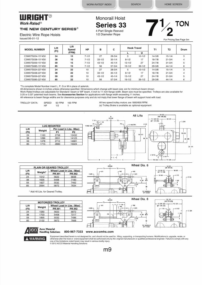
8/21/2019 2013 Wright Specifications Catalog
http://slidepdf.com/reader/full/2013-wright-specifications-catalog 58/189
WORK-RATED® INDEX SEARCH HOME SCREEN
* Add 40 Lbs. for Geared Trolley.
PLAIN OR GEARED TROLLEY Lift(Ft) Weight* Wheel Load in Lbs. (Max)
PR.W1 PR.W2 24
1512
5622
6838
38 1635 5408 7183
59
1827
5532
7462
85 2064 5872 7634
Monorail Hoist
Series 334 Part Single Reeved
1/2 Diameter Rope
All two speed trolley motors are 1800/600 RPM.
(a) Trolley Brake is available as optional equipment
LUG MOUNTED Lift
(Ft) Weight Pin Load in Lbs. (Max) P1 P2
24
1163
2758
13432
38
1286
2651
14123
59 1478 2712 14681
85
1715
2883
15024
MOTORIZED TROLLEY Lift
(Ft) Weight Wheel Load in Lbs. (Max) PR.W1 PR.W2
24
1580
5622
6872
38 1703 5408 7217
59
1895
5532
7496
85
2132
5872
7668
Electric Wire Rope HoistsIssued 06-01-12
Equipment described herein is not designed for, and should not be used for, lifting, supporting, or transporting humans. Modifications to upgrade, rerate, orotherwise alter the hoist or crane equipment shall be authorized only by the original manufacturer or qualified professional engineer. Failure to comply with anyone of the limitations noted herein may result in serious bodily injury.© 2012 ACCO Material Handling Solutions
m9
800-967-7333 www.accomhs.com
MODEL NUMBERLift
(Ft)
Lift
Speed(FPM)
HP B CHook Travel
T1 T2 DrumL U
C3W07S024-15*4S0 24 15 7-1/2 27 28-3/4 5 10-1/2 14-3/8 15-1/4 3
C3W07S038-15*4S0 38 15
7-1/2
33-1/2
35-1/4
8-1/2
17
18-7/8
21-3/4
4
C3W07S059-15*4S0 59 15
7-1/2
43-1/2
45-1/4
13-1/2
27
24-7/8
31-3/4
5
C3W07S085-15*4S0 85 15 7-1/2 56 57-3/4 19-1/2 39-1/2 29-3/8 44-1/4 6
C3W07S024-22*4S0 24 22
10
27
28-3/4
5
10-1/2
14-3/8
15-1/4
3
C3W07S038-22*4S0 38 22 10 33-1/2 35-1/4 8-1/2 17 18-7/8 21-3/4 4
C3W07S059-22*4S0 59 22 10 43-1/2 45-1/4 13-1/2 27 24-7/8 31-3/4 5
C3W07S085-22*4S0 85 22
10
56
57-3/4
19-1/2
39-1/2
29-3/8
44-1/4
6
*To complete Model Number insert L, P, G or M in place of asterick.All dimensions shown in inches unless otherwise specified. Dimensions which change with beam size are for minimum beam shown.Work-Rated trolleys are adjustable for Standard I beam or WF beam, 4 inch to 11 inch flange width. Beam size must be specified. Trolleys are also available for3.25 or 3.33" patented track beams. See Accessories Section for applications with flange width exceeding 11 inches.
All reference to beam flange widths are for clearance purposes only and do not imply that lower flange of beam will support hoist with load.
TROLLEY DATA: SPEED 50 FPM 100 FPM
HP 1/2 1
TON
For Pricing See Page 5m
TON71
2

8/21/2019 2013 Wright Specifications Catalog
http://slidepdf.com/reader/full/2013-wright-specifications-catalog 59/189
WORK-RATED® INDEX SEARCH HOME SCREEN
* Add 40 Lbs. for Geared Trolley.
Electric Wire Rope HoistsIssued 06-01-12
Monorail Hoist
Series 342 Part Single Reeved
5/8 Diameter Rope
LUG MOUNTED Lift
(Ft) Weight Pin Load in Lbs. (Max) P1 P2
21 1640 8498 18702
53 1830 8143 17057
71 1980 9062 16528
97 2120 8603 16677
143 2400 10200 16590
206 2780 9791 16779
PLAIN OR GEARED TROLLEY Lift(Ft) Weight* Wheel Load in Lbs. (Max)
PR.W1 PR.W2 21 2077 9429 5490
53 2331 7570 6615
71 2460 4531 8264
97 2600 4422 8459
143 2880 5220 8415
206 3260 5016 8510
MOTORIZED TROLLEY
Lift(Ft) Weight Wheel Load in Lbs. (Max) PR.W1 PR.W2 21 2145 6159 5524
53 2400 4100 6649
71 2528 4531 8298
97 2668 4422 8493
143 2948 5220 8449
206 3328 5016 8544
All two speed trolley motors are 1800/600 RPM.
(a) Trolley Brake is available as optional equipment
Equipment described herein is not designed for, and should not be used for, lifting, supporting, or transporting humans. Modifications to upgrade, rerate, orotherwise alter the hoist or crane equipment shall be authorized only by the original manufacturer or qualified professional engineer. Failure to comply with anyone of the limitations noted herein may result in serious bodily injury.© 2012 ACCO Material Handling Solutions
m10
800-967-7333 www.accomhs.com
MODEL NUMBER
Lift(Ft)
Lift
HP
B
C
Hook Travel Lug Mounted Trolley Mounted
Drum
Speed L
U
T1
T2
T1
T2
(FPM)
C4W07S021-30*2S0 21 30
15
18-9/16
22-718
5/8
4-9/16
3-718
3-7/8
10-3/4
10-1/4
1
C4W07S053-30*2S0 53 30
15
24-1/2
30-3/8
5/8
12-1/16
11-3/8
11-3/8
18-1/4
17-3/4
2
C4W07S071-30*2S0 71 30 15 29 34-7/8 5/8 16-9/16 13-3/8 16-5/8 13-3/8 16-5/8 3
C4W07S097-30*2S0 97 30
15
35
40-7/8
5/8
22-9/16
19-3/8
22-5/8
19-3/8
22-5/8
4
C4W07S143-30*2S0 143 30
15
46
51-7/8
5/8
33-9/16
20-3/8
33-5/8
20-3/8
33-5/8
5
C4W07S206-30*2S0 206 30 15 61 66-7/8 5/8 48-9/16 35-3/8 48-5/8 35-3/8 48-5/8 6
*To complete Model Number insert L, P, G or M in place of asterick.All dimensions shown in inches unless otherwise specified. Dimensions which change with beam size are for minimum beam shown.
Work-Rated trolleys are adjustable for Standard I beam or WF beam, 4 inch to 11 inch flange width. Beam size must be specified. Trolleys are also available for3.25 or 3.33" patented track beams. See Accessories Section for applications with flange width exceeding 11 inches.All reference to beam flange widths are for clearance purposes only and do not imply that lower flange of beam will support hoist with load.
TROLLEY DATA: SPEED 50 FPM 100 FPM
HP 1/2 1
For Pricing See Page 5m
TON 71
2

8/21/2019 2013 Wright Specifications Catalog
http://slidepdf.com/reader/full/2013-wright-specifications-catalog 60/189
WORK-RATED® INDEX SEARCH HOME SCREEN
* Add 40 Lbs. for Geared Trolley.
Monorail Hoist
Series 352 Part Single Reeved
3/4 Diameter Rope
All two speed trolley motors are 1800/600 RPM.
(a) Trolley Brake is available as optional equipment
LUG MOUNTED Lift
(Ft) Weight Pin Load in Lbs. (Max) P1 P2
20 2185 8355 18955
51 2450 8197 17593
70 2844 9427 16862
95 3159 9353 16981
133 3624 11335 16859
185 4290 11037 17118
PLAIN OR GEARED TROLLEY Lift(Ft) Weight* Wheel Load in Lbs. (Max)
PR.W1 PR.W2 20 2650 6173 7040
51 2995 6185 7798
70 3352 4841 8558
95 3667 4803 8618
133 4132 5795 8556
185 4798 5645 8686
MOTORIZED TROLLEY
Lift(Ft) Weight Wheel Load in Lbs. (Max) PR.W1 PR.W2 20 2750 6173 7090
51 3095 6185 7848
70 3452 4841 9008
95 3767 4803 8668
133 4232 5795 8606
185 4898 5645 8736
*To complete Model Number insert L, P, G or M in place of asterick.All dimensions shown in inches unless otherwise specified. Dimensions which change with beam size are for minimum beam shown.Work-Rated trolleys are adjustable for Standard I beam or WF beam, 4 inch to 11 inch flange width. Beam size must be specified. Trolleys are also available for
3.25 or 3.33" patented track beams. See Accessories Section for applications with flange width exceeding 11 inches.All reference to beam flange widths are for clearance purposes only and do not imply that lower flange of beam will support hoist with load.
TROLLEY DATA: SPEED 50 FPM 100 FPM
HP 1/2 1
Electric Wire Rope HoistsIssued 06-01-12
Equipment described herein is not designed for, and should not be used for, lifting, supporting, or transporting humans. Modifications to upgrade, rerate, orotherwise alter the hoist or crane equipment shall be authorized only by the original manufacturer or qualified professional engineer. Failure to comply with anyone of the limitations noted herein may result in serious bodily injury.© 2012 ACCO Material Handling Solutions
m11
800-967-7333 www.accomhs.com
MODEL NUMBER
Lift(Ft)
Lift
HP
B
C
Hook Travel Lug Mounted Trolley Mounted
DrumSpeed L
U
T1
T2
T1
T2 (FPM)
C5W07S020-44*2S0 20 44 20 24-1/16 24-1/8 7/16 4-7/16 3-5/8 3-5/8 18-1/4 10 1
C5W07S051-44*2S0 51 44
20
24-7/8
31-5/8
7/16
11-15/16
11-1/8
11-1/8
31-1/2
17-1/2
2
C5W07S070-44*2S0 70 44 20 29-3/8 36-1/8 7/16 16-7/16 13-3/8 16-5/8 13-3/8 16-5/8 3
C5W07S095-44*2S0 95 44 20 35-3/8 42-1/8 7/16 22-7/16 19-3/8 22-5/8 19-3/8 22-5/8 4
C5W07S133-44*2S0 133 44
20
44-3/8
51-1/8
7/16
31-7/16
18-3/8
31-5/8
18-3/8
31-5/8
5
C5W07S185-44*2S0 185 44
20
56-7/8
63-5/8
7/16
43-15/16
30-7/8
44-1/8
30-718
44-1/8
6
For Pricing See Page 5m
TON 71
2

8/21/2019 2013 Wright Specifications Catalog
http://slidepdf.com/reader/full/2013-wright-specifications-catalog 61/189
WORK-RATED® INDEX SEARCH HOME SCREEN
* Add 40 Lbs. for Geared Trolley.
Electric Wire Rope HoistsIssued 06-01-12
Monorail Hoist
Series 334 Part Single Reeved
1/2 Diameter Rope
LUG MOUNTED Lift
(Ft) Weight Pin Load in Lbs. (Max) P1 P2
24 1163 3623 17630
38 1286 3466 18539
59 1478 3526 19261
85 1715 3723 19702
PLAIN OR GEARED TROLLEY Lift
(Ft) Weight* Wheel Load in Lbs. (Max) PR.W1 PR.W2
24 1512 7352 8937
38 1635 7038 9391
59 1827 7158 9752
85 2064 7552 9973
MOTORIZED TROLLEY Lift
(Ft) Weight Wheel Load in Lbs. (Max)
PR.W1 PR.W2 24 1580 7352 8971
38 1703 7038 9425
59 1895 7158 9786
85 2132 7552 10007
*To complete Model Number insert L, P, G or M in place of asterick.All dimensions shown in inches unless otherwise specified. Dimensions which change with beam size are for minimum beam shown.Work-Rated trolleys are adjustable for Standard I beam or WF beam, 4 inch to 11 inch flange width. Beam size must be specified. Trolleys are also available for3.25 or 3.33" patented track beams. See Accessories Section for applications with flange width exceeding 11 inches.All reference to beam flange widths are for clearance purposes only and do not imply that lower flange of beam will support hoist with load.
TROLLEY DATA: SPEED 50 FPM 100 FPM
HP 1/2 1
All two speed trolley motors are 1800/600 RPM.
(a) Trolley Brake is available as optional equipment
Equipment described herein is not designed for, and should not be used for, lifting, supporting, or transporting humans. Modifications to upgrade, rerate, or
otherwise alter the hoist or crane equipment shall be authorized only by the original manufacturer or qualified professional engineer. Failure to comply with anyone of the limitations noted herein may result in serious bodily injury.© 2012 ACCO Material Handling Solutions
m12
800-967-7333 www.accomhs.com
TON 10For Pricing See Page 6m
MODEL NUMBERLift(Ft)
Lift
Speed(FPM)
HP B CHook Travel
T1 T2 DrumL U
C3W10S024-15*4S0 24 15 10 27 28-3/4 5 10-1/2 14-3/8 15-1/4 3
C3W10S038-15*4S0 38 15
10
33-1/2
35-1/4
8-1/2
17
18-7/8
21-3/4
4
C3W10S059-15*4S0 59 15
10
43-1/2
45-1/4
13-1/2
27
24-7/8
31-3/4
5
C3W10S085-15*4S0 85 15 10 56 57-3/4 19-1/2 39-1/2 29-3/8 44-1/4 6

8/21/2019 2013 Wright Specifications Catalog
http://slidepdf.com/reader/full/2013-wright-specifications-catalog 62/189
WORK-RATED® INDEX SEARCH HOME SCREEN
* Add 40 Lbs. for Geared Trolley.
Monorail Hoist
Series 344 Part Single Reeved
5/8 Diameter Rope
All two speed trolley motors are 1800/600 RPM.
(a) Trolley Brake is available as optional equipment
LUG MOUNTED Lift
(Ft) Weight Pin Load in Lbs. (Max) P1 P2
25 2040 12722 16688
38 2190 12422 17918
61 2500 3238 21994
92 2870 2766 22129
PLAIN OR GEARED TROLLEY Lift
(Ft) Weight* Wheel Load in Lbs. (Max) PR.W1 PR.W2
25 2728 6981 6141
38 2909 6851 6861
61 3223 6576 5654
92 3593 5631 5688
MOTORIZED TROLLEY Lift(Ft) Weight Wheel Load in Lbs. (Max)
PR.W1 PR.W2 PR.W3 25 2796 7015 6141 -
38 2977 6885 6861 -
61 3291 6576 5688 5654
92 3661 5631 5722 5688
*To complete Model Number insert L, P, G or M in place of asterisk.All dimensions shown in inches unless otherwise specified. Dimensions which change with beam size are for minimum beam shown.Work-Rated trolleys are adjustable for Standard I beam or WF beam, 4 inch to 11 inch flange width. Beam size must be specified. Trolleys are also available for3.25 or 3.33" patented track beams. See Accessories Section for applications with flange width exceeding 11 inches.
All reference to beam flange widths are for clearance purposes only and do not imply that lower flange of beam will support hoist with load.
25, 38 Foot LiftsTROLLEY DATA: SPEED 50 FPM 100 FPM
HP 1/2 1
61, 92 Foot LiftsTROLLEY DATA: SPEED 50 FPM 100 FPM
HP 1/2 (2 REQUIRED) 1/2 (2 REQUIRED)
Electric Wire Rope HoistsIssued 06-03-13
Equipment described herein is not designed for, and should not be used for, lifting, supporting, or transporting humans. Modifications to upgrade, rerate, orotherwise alter the hoist or crane equipment shall be authorized only by the original manufacturer or qualified professional engineer. Failure to comply with anyone of the limitations noted herein may result in serious bodily injury.© 2013 ACCO Material Handling Solutions
m13
800-967-7333 www.accomhs.com
MODEL NUMBER
Lift(Ft)
Lift
Speed(FPM)
HP
B
C
Hook Travel Lug Mounted Trolley Mounted
Drum
L
U
T1
T2
T1
T2
C4W10S025-22*4S0 25 22
15
29
34-7/8
5-15/16
11-5/8
3/8
15-3/8
6-3/8
26-5/8
3
C4W10S038-22*4S0 38 22
15
35
40-7/8
8-15/16
17-518
3/8
21-3/8
6-3/8
32-5/8
4
C4W10S061-22*4S0 61 22 15 46 51-7/8 14-7116 28-5/8 32-7/8 28-5/8 32-7/8 28-5/8 5
C4W10S092-22*4S0 92 22
15
61
66-7/8
21-15/16
43-5/8
47-7/8
43-5/8
47-7/8
43-5/8
6
TON 10For Pricing See Page 6m
Wheel Dia. 6
Wheel Dia. 6

8/21/2019 2013 Wright Specifications Catalog
http://slidepdf.com/reader/full/2013-wright-specifications-catalog 63/189
WORK-RATED® INDEX SEARCH HOME SCREEN
* Add 40 Lbs. for Geared Trolley.
Electric Wire Rope HoistsIssued 06-01-12
Monorail Hoist
Series 352 Part Single Reeved
3/4 Diameter Rope
LUG MOUNTED Lift
(Ft) Weight Pin Load in Lbs. (Max) P1 P2
20 2185 11170 24515
51 2450 10797 22773
70 2844 12272 21832
95 3159 12103 21956
133 3624 14545 21839
185 4290 14007 22103
PLAIN OR GEARED TROLLEY Lift(Ft) Weight* Wheel Load in Lbs. (Max)
PR.W1 PR.W2 20 2650 8021 9050
51 2995 8015 10014
70 3352 6263 11043
95 3667 6178 11105
133 4132 7399 11046
185 4798 7130 11179
MOTORIZED TROLLEY
Lift(Ft) Weight Wheel Load in Lbs. (Max) PR.W1 PR.W2 20 2750 8021 9100
51 3095 8015 10064
70 3452 6263 11093
95 3767 6178 11155
133 4232 7399 11096
185 4898 7130 11229
*To complete Model Number insert L, P, G or M in place of asterick.All dimensions shown in inches unless otherwise specified. Dimensions which change with beam size are for minimum beam shown.Work-Rated trolleys are adjustable for Standard I beam or WF beam, 4 inch to 11 inch flange width. Beam size must be specified. Trolleys are also available for3.25 or 3.33" patented track beams. See Accessories Section for applications with flange width exceeding 11 inches.All reference to beam flange widths are for clearance purposes only and do not imply that lower flange of beam will support hoist with load.
TROLLEY DATA: SPEED 50 FPM 100 FPM
HP 1/2 1
All two speed trolley motors are 1800/600 RPM.
(a) Trolley Brake is available as optional equipment
Equipment described herein is not designed for, and should not be used for, lifting, supporting, or transporting humans. Modifications to upgrade, rerate, orotherwise alter the hoist or crane equipment shall be authorized only by the original manufacturer or qualified professional engineer. Failure to comply with anyone of the limitations noted herein may result in serious bodily injury.
© 2012 ACCO Material Handling Solutions
m14
800-967-7333 www.accomhs.com
MODEL NUMBER
Lift(Ft)
LiftSpeed(FPM)
HP
B
C
Hook Travel Lug MountedTrolley
Mounted Drum
L U T1 T2 T1 T2
C5W10S020-30*2S0 20 30
20
24-1/16
24-1/8
7/16
4-7/16
3-5/8
3-5/8
18-1/4
10
1
C5W108051-30*2S0 51 30
20
24-7/8
31-5/8
7/16
11-15/16
11-1/8
11-1/8
31-1/2
17-1/2
2
C5W10S070-30*2S0 70 30 20 29-3/8 36-1/8 7/16 16-7/16 13-3/8 16-5/8 13-3/8 16-5/8 3
C5W10S095-30*2S0 95 30 20 35-3/8 42-1/8 7/16 22-7/16 19-3/8 22-5/8 19-3/8 22-5/8 4
C5W10S133-30*2S0 133 30
20
44-3/8
51-1/8
7/16
31-7/16
18-3/8
31-5/8
18-3/8
31-5/8
5
C5W10S185-30*2S0 185 30
20
56-7/8
63-5/8
7/16
43-15/16
30-718
44-1/8
30-718
44-1/8
6
TON 10For Pricing See Page 6m
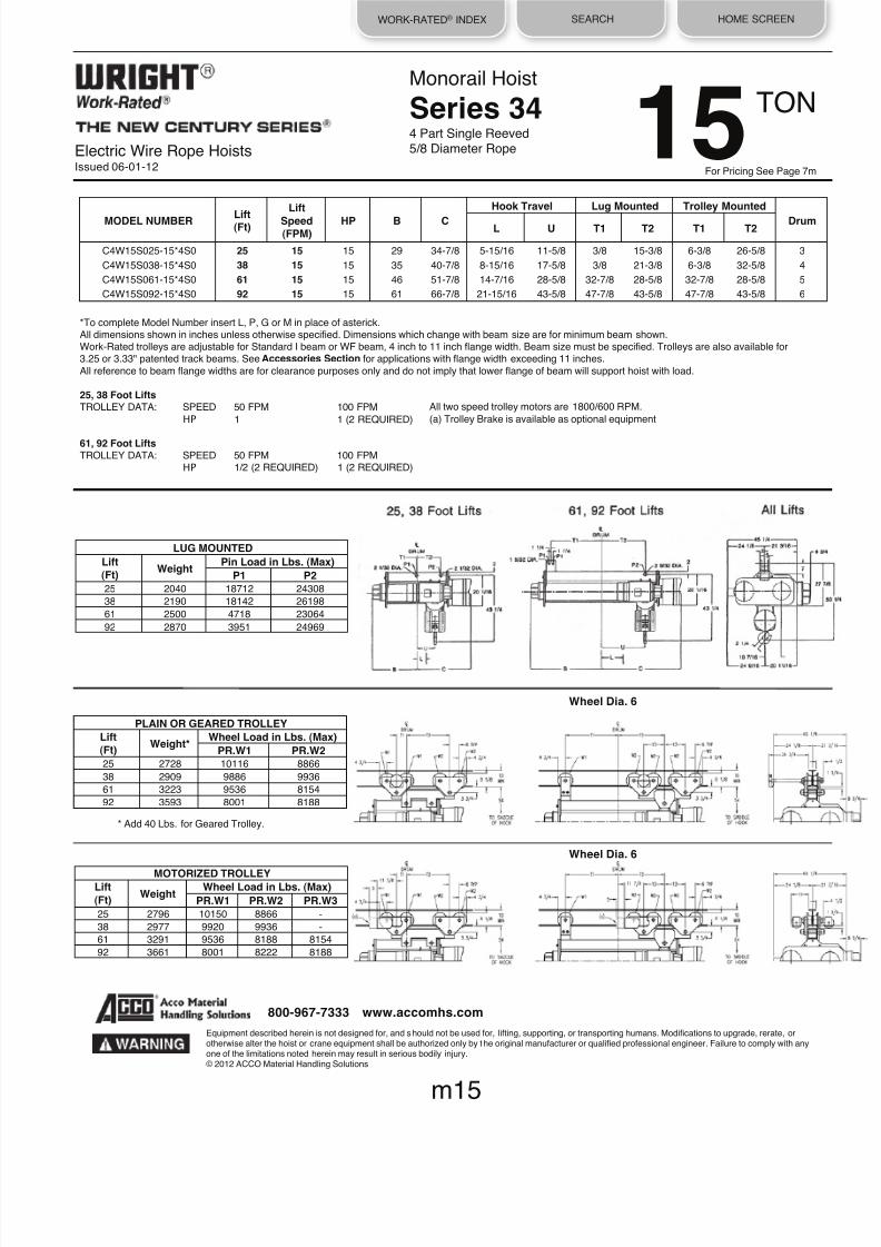
8/21/2019 2013 Wright Specifications Catalog
http://slidepdf.com/reader/full/2013-wright-specifications-catalog 64/189
WORK-RATED® INDEX SEARCH HOME SCREEN
* Add 40 Lbs. for Geared Trolley.
Monorail Hoist
Series 344 Part Single Reeved5/8 Diameter Rope
LUG MOUNTED Lift
(Ft) Weight Pin Load in Lbs. (Max) P1 P2
25 2040 18712 24308
38
2190
18142
26198
61 2500 4718 23064
92 2870 3951 24969
PLAIN OR GEARED TROLLEY Lift
(Ft) Weight* Wheel Load in Lbs. (Max) PR.W1 PR.W2
25 2728 10116 8866
38 2909 9886 9936
61
3223
9536
8154
92 3593 8001 8188
MOTORIZED TROLLEY Lift
(Ft) Weight Wheel Load in Lbs. (Max) PR.W1 PR.W2 PR.W3
25
2796
10150
8866
-
38 2977 9920 9936 -
61
3291
9536
8188
8154
92 3661 8001 8222 8188
All two speed trolley motors are 1800/600 RPM.
(a) Trolley Brake is available as optional equipment
*To complete Model Number insert L, P, G or M in place of asterick.All dimensions shown in inches unless otherwise specified. Dimensions which change with beam size are for minimum beam shown.Work-Rated trolleys are adjustable for Standard I beam or WF beam, 4 inch to 11 inch flange width. Beam size must be specified. Trolleys are also available for3.25 or 3.33" patented track beams. See Accessories Section for applications with flange width exceeding 11 inches.
All reference to beam flange widths are for clearance purposes only and do not imply that lower flange of beam will support hoist with load.
25, 38 Foot LiftsTROLLEY DATA: SPEED 50 FPM 100 FPM
HP 1 1 (2 REQUIRED)
61, 92 Foot LiftsTROLLEY DATA: SPEED 50 FPM 100 FPM
HP 1/2 (2 REQUIRED) 1 (2 REQUIRED)
Electric Wire Rope HoistsIssued 06-01-12
Equipment described herein is not designed for, and should not be used for, lifting, supporting, or transporting humans. Modifications to upgrade, rerate, orotherwise alter the hoist or crane equipment shall be authorized only by the original manufacturer or qualified professional engineer. Failure to comply with anyone of the limitations noted herein may result in serious bodily injury.© 2012 ACCO Material Handling Solutions
m15
800-967-7333 www.accomhs.com
MODEL NUMBER
Lift(Ft)
Lift
Speed(FPM)
HP
B
C
Hook Travel Lug Mounted Trolley Mounted
Drum
L
U
T1
T2
T1
T2
C4W15S025-15*4S0 25 15
15
29
34-7/8
5-15/16
11-5/8
3/8
15-3/8
6-3/8
26-5/8
3
C4W15S038-15*4S0 38 15 15 35 40-7/8 8-15/16 17-5/8 3/8 21-3/8 6-3/8 32-5/8 4
C4W15S061-15*4S0 61 15 15 46 51-7/8 14-7/16 28-5/8 32-7/8 28-5/8 32-7/8 28-5/8 5
C4W15S092-15*4S0 92 15
15
61
66-7/8
21-15/16
43-5/8
47-7/8
43-5/8
47-7/8
43-5/8
6
TON 15For Pricing See Page 7m
Wheel Dia. 6
Wheel Dia. 6

8/21/2019 2013 Wright Specifications Catalog
http://slidepdf.com/reader/full/2013-wright-specifications-catalog 65/189
WORK-RATED® INDEX SEARCH HOME SCREEN
* Add 40 Lbs. for Geared Trolley.
Electric Wire Rope HoistsIssued 06-01-12
Monorail Hoist
Series 354 Part Single Reeved
3/4 Diameter Rope
LUG MOUNTED Lift(Ft) Weight Pin Load in Lbs. (Max)
P1 P2 21
2812
15970
24342
34 3110 16441 25879
53
3334
9281
31223
79 4300 9703 31859
PLAIN OR GEARED TROLLEY Lift(Ft) Weight* Wheel Load in Lbs. (Max)
PR.W1 PR.W2 21
3540
9399
9419
34 3868 9427 10307
53
4231
9535
7967
79 5197 9957 8125
All two speed trolley motors are 1800/600 RPM.(a) Trolley Brake is available as optional equipment
*To complete Model Number insert L, P, G or M in place of asterick.All dimensions shown in inches unless otherwise specified. Dimensions which change with beam size are for minimum beam shown.Work-Rated trolleys are adjustable for Standard I beam or WF beam, 4 inch to 11 inch flange width. Beam size must be specified. Trolleys are also available for3.25 or 3.33" patented track beams. See Accessories Section for applications with flange width exceeding 11 inches.All reference to beam flange widths are for clearance purposes only and do not imply that lower flange of beam will support hoist with load.
21, 34 Foot LiftsTROLLEY DATA: SPEED 50 FPM 100 FPM
HP 1 1 (2 REQUIRED)
53, 79 Foot LiftsTROLLEY DATA: SPEED 50 FPM 100 FPM
HP 1/2 (2 REQUIRED) 1 (2 REQUIRED)
MOTORIZED TROLLEY Lift
(Ft) Weight Wheel Load in Lbs. (Max)
PR.W1 PR.W2 PR.W3 21
3640
9449
9419
-
34 3968 9477 10307 -
53 4331 9535 8017 7967
79
5297
9957
8175
8125
Equipment described herein is not designed for, and should not be used for, lifting, supporting, or transporting humans. Modifications to upgrade, rerate, orotherwise alter the hoist or crane equipment shall be authorized only by the original manufacturer or qualified professional engineer. Failure to comply with anyone of the limitations noted herein may result in serious bodily injury.© 2012 ACCO Material Handling Solutions
m16
800-967-7333 www.accomhs.com
MODEL NUMBER
Lift(Ft)
Lift
Speed(FPM)
HP
B
C
Hook Travel Lug Mounted Trolley Mounted
Drum
L
U
T1
T2
T1
T2
C5W15S021-22*4S0 21 22 20 29-3/8 36-1/8 4-13/16 10 5-5/8 15-1/8 11-5/8 26-3/8 3
C5W15S034-22*4S0 34 22 20 35-3/8 42-1/8 7-13/16 16 5-5/8 21-1/8 11-5/8 32-3/8 4
C5W15S053-22*4S0 53 22
20
44-3/8
51-1/8
12-5/16
25
26-5/8
26-5/8
26-5/8
26-5/8
5
C5W15S079-22*4S0 79 22
20
56-7/8
63-5/8
18-9/16
37-1/2
39-1/8
39-1/8
39-1/8
39-1/8
6
TON 15For Pricing See Page 7m
Wheel Dia. 6
Wheel Dia. 6

8/21/2019 2013 Wright Specifications Catalog
http://slidepdf.com/reader/full/2013-wright-specifications-catalog 66/189
WORK-RATED® INDEX SEARCH HOME SCREEN
* Add 40 Lbs. for Geared Trolley.
Monorail Hoist
Series 354 Part Single Reeved
3/4 Diameter Rope
All two speed trolley motors are 1800/600 RPM.
(a) Trolley Brake is available as optional equipment
LUG MOUNTED Lift
(Ft) Weight Pin Load in Lbs. (Max) P1 P2
21 2812 3897 42558
34
3110
10497
40793
53 3334 11971 40923
79 4300 12333 41647
PLAIN OR GEARED TROLLEY Lift(Ft) Weight* Wheel Load in Lbs. (Max)
PR.W1 PR.W2 21
3567
7906
10800
34 4007 10751 10359
53
4231
12225
10392
79 5197 12587 10573
*To complete Model Number insert L, P, G or M in place of asterick.All dimensions shown in inches unless otherwise specified. Dimensions which change with beam size are for minimum beam shown.Work-Rated trolleys are adjustable for Standard I beam or WF beam, 4 inch to 11 inch flange width. Beam size must be specified. Trolleys are also available for3.25 or 3.33" patented track beams. See Accessories Section for applications with flange width exceeding 11 inches.All reference to beam flange widths are for clearance purposes only and do not imply that lower flange of beam will support hoist with load.
TROLLEY DATA: SPEED 50 FPM 100 FPMHP 1/2 (2 REQUIRED) 1 (2 REQUIRED)
MOTORIZED TROLLEY Lift
(Ft) Weight Wheel Load in Lbs. (Max) PR.W1 PR.W2 PR.W3
21 3667 7906 10850 10800
34
4107
10751
10389
10359
53
4331
12225
10442
10392
79
5297
12587
10623
10573
Electric Wire Rope HoistsIssued 06-01-12
Equipment described herein is not designed for, and should not be used for, lifting, supporting, or transporting humans. Modifications to upgrade, rerate, orotherwise alter the hoist or crane equipment shall be authorized only by the original manufacturer or qualified professional engineer. Failure to comply with anyone of the limitations noted herein may result in serious bodily injury.© 2012 ACCO Material Handling Solutions
m17
800-967-7333 www.accomhs.com
MODEL NUMBER
Lift
(Ft)
Lift
Speed(FPM)
HP B C
Hook Travel
T1 T2 DrumL U
C5W20S021-15*4S0 21 15
20
29-3/8
36-1/8
4-13/16
10
17-5/8
10
3
C5W20S034-15*4S0 34 15 20 35-3/8 42-1/8 7-13/16 16 21-5/8 17-5/8 4
C5W20S053-15*4S0 53 15 20 44-3/8 51-1/8 12-5/16 25 26-5/8 26-5/8 5
C5W20S079-15*4S0 79 15
20
56-7/8
63-5/8
18-9/16
37-1/2
39-1/8
39-1/8
6
TON 20For Pricing See Page 8m
Wheel Dia. 6
Wheel Dia. 6

8/21/2019 2013 Wright Specifications Catalog
http://slidepdf.com/reader/full/2013-wright-specifications-catalog 67/189
WORK-RATED® INDEX SEARCH HOME SCREEN
* Add 40 Lbs. for Geared Trolley.
Electric Wire Rope HoistsIssued 06-01-12
Monorail Hoist
Series 322 Part Double Reeved
3/8 Diameter Rope
LUG MOUNTED Lift(Ft) Weight Pin Load in Lbs. (Max)
P1 P2 20 688 1572 558
36
779
1649
565
60 933 1773 580
85
1082
1901
591
PLAIN OR GEARED TROLLEY Lift
(Ft) Weight* Wheel Load in Lbs. (Max) PR.W1 PR.W2
20 816 827 1163
36 907 865 1177
60
1061
927
1207
85 1210 991 1229
All two speed trolley motors are 1800/600 RPM.(a) Trolley Brake is available as optional equipment
*To complete Model Number insert L, P, G or M in place of asterick.All dimensions shown in inches unless otherwise specified. Dimensions which change with beam size are for minimum beam shown.
Work-Rated trolleys are adjustable for Standard I beam or WF beam, 4 inch to 11 inch flange width. Beam size must be specified. Trolleys are also available for3.25 or 3.33" patented track beams. See Accessories Section for applications with flange width exceeding 11 inches.All reference to beam flange widths are for clearance purposes only and do not imply that lower flange of beam will support hoist with load.
TROLLEY DATA: SPEED 50 FPM 100 FPM
HP 1/2 1/2
MODEL NUMBER
Lift
(Ft)
Lift
Speed (FPM)
HP
B
C
T1
T2
Drum
C2W01D020-15*2D0 20 15 3 23-3/8 25-7/8 5-1/8 11-3/8 4
C2W01D036-15*2D0 36 15 3 30-7/8 33-3/8 8-5/8 18-7/8 6
C2W01D060-15*2D0 60 15
3
42
44-1/2
13-1/2
30
7
C2W01D085-15*2D0 85 15
3
53-3/4
56-1/4
18-1/4
41-3/4
8
C2W01D020-22*2D0 20 22
3
23-3/8
25-7/8
5-1/8
11-3/8
4
C2W01D036-22*2D0 36 22
3
30-7/8
33-3/8
8-5/8
18-7/8
6
C2W01D060-22*2D0 60 22 3 42 44-1/2 13-1/2 30 7
C2W01D085-22*2D0 85 22 3 53-3/4 56-1/4 18-1/4 41-3/4 8
C2W01D020-30*2D0 20 30 3 23-3/8 25-7/8 5-1/8 11-3/8 4
C2W01D036-30*2D0 36 30 3 30-7/8 33-3/8 8-5/8 18-7/8 6
C2W01D060-30*2D0 60 30
3
42
44-1/2
13-1/2
30
7
C2W01D085-30*2D0 85 30
3
53-3/4
56-1/4
18-1/4
41-3/4
8
MOTORIZED TROLLEY Lift(Ft) Weight Wheel Load in Lbs. (Max)
PR.W1 PR.W2 20
884
858
1163
36 975 899 1177
60
1129
958
1207
85 1278 1025 1229
Equipment described herein is not designed for, and should not be used for, lifting, supporting, or transporting humans. Modifications to upgrade, rerate, orotherwise alter the hoist or crane equipment shall be authorized only by the original manufacturer or qualified professional engineer. Failure to comply with anyone of the limitations noted herein may result in serious bodily injury.© 2012 ACCO Material Handling Solutions
m18
800-967-7333 www.accomhs.com
TON 1For Pricing See Page 9m

8/21/2019 2013 Wright Specifications Catalog
http://slidepdf.com/reader/full/2013-wright-specifications-catalog 68/189
WORK-RATED® INDEX SEARCH HOME SCREEN
Monorail Hoist
Series 332 Part Double Reeved
3/8 Diameter Rope
LUG MOUNTED Lift(Ft) Weight Pin Load in Lbs. (Max)
P1 P2 20 986 1689 649
36
1080 1632 724
54 1189 1720 735
82
1360 1897 732
118
1572 2005 784
PLAIN OR GEARED TROLLEY
Lift
(Ft) Weight* Wheel Load in Lbs. (Max) PR.W1 PR.W2
20 1177 911 1357
36
1271 882 1507
54 1380 926 1529
82 1551 1015 1523
118
1763 1069 1627
* Add 40 Lbs. for Geared Trolley
MOTORIZED TROLLEY Lift(Ft) Weight Wheel Load in Lbs. (Max)
PR.W1 PR.W2 20 1245 945 1357
36
1339 916 1507
54
1448 960 152982
1619 1049 1523
118
1831 1103 1627
*To complete Model Number insert L, P, G or M in place of asterick.All dimensions shown in inches unless otherwise specified. Dimensions which change with beam size are for minimum beam shown.Work-Rated trolleys are adjustable for Standard I beam or WF beam, 4 inch to 11 inch flange width. Beam size must be specified. Trolleys are also available for3.25 or 3.33" patented track beams. See Accessories Section for applications with flange width exceeding 11 inches.
All reference to beam flange widths are for clearance purposes only and do not imply that lower flange of beam will support hoist with load.
TROLLEY DATA: SPEED 50 FPM 100 FPMHP 1/2 1/2
Electric Wire Rope HoistsIssued 06-01-12
All two speed trolley motors are 1800/600 RPM.
(a) Trolley Brake is available as optional equipment
Equipment described herein is not designed for, and should not be used for, lifting, supporting, or transporting humans. Modifications to upgrade, rerate, orotherwise alter the hoist or crane equipment shall be authorized only by the original manufacturer or qualified professional engineer. Failure to comply with anyone of the limitations noted herein may result in serious bodily injury.© 2012 ACCO Material Handling Solutions
m19
800-967-7333 www.accomhs.com
MODEL NUMBER
Lift
(Ft)
Lift
Speed (FPM)
HP
B
C
T1
T2
Drum
C3W01D020-44*2D0 20 44
7-1/2
21-1/8
23-5/8
4-5/8
8-7/8
2
C3W01D036-44*2D0 36 44 7-1/2 26-5/8 29-1/8 7-5/8 14-3/8 3
C3W01D054-44*2D0 54 44
7-1/2
33-1/8
35-5/8
11-1/8
20-718
4
C3W01D082-44*2D0 82 44
7-1/2
43-1/8
45-5/8
15-1/8
30-7/8
5
C3W01D118-44*2D0 118 44 7-1/2 55-5/8 58-1/8 22-5/8 43-3/8 6
TON1For Pricing See Page 9m

8/21/2019 2013 Wright Specifications Catalog
http://slidepdf.com/reader/full/2013-wright-specifications-catalog 69/189
WORK-RATED® INDEX SEARCH HOME SCREEN
* Add 40 Lbs. for Geared Trolley.
Electric Wire Rope HoistsIssued 06-01-12
Monorail Hoist
Series 322 Part Double Reeved
3/8 Diameter Rope
LUG MOUNTED Lift(Ft) Weight Pin Load in Lbs. (Max)
P1 P2 20 688 2950 869
36
779
3022
879
60 933 3153 890
85
1082
3293
895
PLAIN OR GEARED TROLLEY Lift(Ft) Weight* Wheel Load in Lbs. (Max)
PR.W1 PR.W2 20
816
1516
1785
36 907 1552 1805
60
1061
1617
1827
85 1210 1687 1837
All two speed trolley motors are 1800/600 RPM.(a) Trolley Brake is available as optional equipment
*To complete Model Number insert L, P, G or M in place of asterick.All dimensions shown in inches unless otherwise specified. Dimensions which change with beam size are for minimum beam shown.
Work-Rated trolleys are adjustable for Standard I beam or WF beam, 4 inch to 11 inch flange width. Beam size must be specified. Trolleys are also available for3.25 or 3.33" patented track beams. See Accessories Section for applications with flange width exceeding 11 inches.All reference to beam flange widths are for clearance purposes only and do not imply that lower flange of beam will support hoist with load.
TROLLEY DATA: SPEED 50 FPM 100 FPM
HP 1/2 1/2
MOTORIZED TROLLEY Lift(Ft) Weight Wheel Load in Lbs. (Max)
PR.W1 PR.W2 20
884
1551
1785
36 975 1586 1805
60
1129
1651
1827
85 1278 1721 1837
Equipment described herein is not designed for, and should not be used for, lifting, supporting, or transporting humans. Modifications to upgrade, rerate, orotherwise alter the hoist or crane equipment shall be authorized only by the original manufacturer or qualified professional engineer. Failure to comply with anyone of the limitations noted herein may result in serious bodily injury.© 2012 ACCO Material Handling Solutions
m20
800-967-7333 www.accomhs.com
MODEL NUMBER
Lift
(Ft)
Lift
Speed (FPM)
HP
B
C
T1
T2
Drum
C2W02D020-15*2D0 20 15
3
23-3/8
25-7/8
5-1/8
11-3/8
4
C2W02D036-15*2D0 36 15 3 30-7/8 33-3/8 8-5/8 18-7/8 6
C2W02D060-15*2D0 60 15 3 42 44-1/2 13-1/2 30 7
C2W02D085-15*2D0 85 15
3
53-3/4
56-1/4
18-1/4
41-3/4
8
C2W02D020-22*2D0 20 22 3 23-3/8 25-7/8 5-1/8 11-3/8 4
C2W02D036-22*2D0 36 22
3
30-7/8
33-3/8
8-5/8
18-7/8
6
C2W02D060-22*2D0 60 22
3
42
44-1/2
13-1/2
30
7
C2W02D085-22*2D0 85 22 3 53-3/4 56-1/4 18-1/4 41-3/4 8
C2W02D020-30*2D0 20 30
5
23-3/8
25-7/8
5-1/8
11-3/8
4
C2W02D036-30*2D0 36 30 5 30-7/8 33-3/8 8-5/8 18-7/8 6
C2W02D060-30*2D0 60 30 5 42 44-1/2 13-1/2 30 7
C2W02D085-30*2D0 85 30
5
53-3/4
56-1/4
18-1/4
41-3/4
8
TON 2For Pricing See Page 10m

8/21/2019 2013 Wright Specifications Catalog
http://slidepdf.com/reader/full/2013-wright-specifications-catalog 70/189
WORK-RATED® INDEX SEARCH HOME SCREEN
* Add 40 Lbs. for Geared Trolley.
Monorail Hoist
Series 332 Part Double Reeved
3/8 Diameter Rope
All two speed trolley motors are 1800/600 RPM.(a) Trolley Brake is available as optional equipment
LUG MOUNTED Lift(Ft) Weight Pin Load in Lbs. (Max)
P1 P2 20
986 2945 1021
36 1080 2939 1071
54
1189 3025 1082
82 1360 3239 1061
118
1572 3320 1126
PLAIN OR GEARED TROLLEY Lift(Ft) Weight* Wheel Load in Lbs. (Max)
PR.W1 PR.W2 20
1177 1539 2101
36 1271 1536 2201
54
1380 1579 2223
82 1551 1686 2181
118 1763 1726 2311
MOTORIZED TROLLEY Lift(Ft) Weight Wheel Load in Lbs. (Max)
PR.W1 PR.W2 20 1245 1573 2101
36
1339 1570 2201
54 1448 1613 2223
82
1619 1720 2181
118 1831 1760 2311
Electric Wire Rope HoistsIssued 06-01-12
Equipment described herein is not designed for, and should not be used for, lifting, supporting, or transporting humans. Modifications to upgrade, rerate, orotherwise alter the hoist or crane equipment shall be authorized only by the original manufacturer or qualified professional engineer. Failure to comply with anyone of the limitations noted herein may result in serious bodily injury.© 2012 ACCO Material Handling Solutions
m21
800-967-7333 www.accomhs.com
MODEL NUMBER
Lift
(Ft)
Lift
Speed (FPM)
HP
B
C
T1
T2
Drum
C3W02D020-44*2D0 20 44 7-1/2 21-1/8 23-5/8 4-5/8 8-7/8 2
C3W02D036-44*2D0 36 44
7-1/2
26-5/8
29-1/8
7-5/8
14-3/8
3
C3W02D054-44*2D0 54 44
7-1/2
33-1/8
35-5/8
11-1/8
20-718
4
C3W02D082-44*2D0 82 44 7-1/2 43-1/8 45-5/8 15-1/8 30-7/8 5
C3W02D118-44*2D0 118 44
7-1/2
55-5/8
58-1/8
22-5/8
43-3/8
6
*To complete Model Number insert L, P, G or M in place of asterick.All dimensions shown in inches unless otherwise specified. Dimensions which change with beam size are for minimum beam shown.
Work-Rated trolleys are adjustable for Standard I beam or WF beam, 4 inch to 11 inch flange width. Beam size must be specified. Trolleys are also available for3.25 or 3.33" patented track beams. See Accessories Section for applications with flange width exceeding 11 inches.All reference to beam flange widths are for clearance purposes only and do not imply that lower flange of beam will support hoist with load.
TROLLEY DATA: SPEED 50 FPM 100 FPM
HP 1/2 1/2
TON2For Pricing See Page 10m

8/21/2019 2013 Wright Specifications Catalog
http://slidepdf.com/reader/full/2013-wright-specifications-catalog 71/189
WORK-RATED® INDEX SEARCH HOME SCREEN
* Add 40 Lbs. for Geared Trolley.
Electric Wire Rope HoistsIssued 06-01-12
Monorail Hoist
Series 322 Part Double Reeved
3/8 Diameter Rope
LUG MOUNTED Lift(Ft) Weight Pin Load in Lbs. (Max)
P1 P2 20
688
4329
1180
36 779 4395 1192
60
933
4532
1201
85 1082 4685 1199
PLAIN OR GEARED TROLLEY Lift(Ft) Weight* Wheel Load in Lbs. (Max)
PR.W1 PR.W2 20 816 2205 2407
36
907
2238
2431
60 1061 2307 2449
85
1210
2383
2445
All two speed trolley motors are 1800/600 RPM.
(a) Trolley Brake is available as optional equipment
*To complete Model Number insert L, P, G or M in place of asterick.All dimensions shown in inches unless otherwise specified. Dimensions which change with beam size are for minimum beam shown.Work-Rated trolleys are adjustable for Standard I beam or WF beam, 4 inch to 11 inch flange width. Beam size must be specified. Trolleys are also available for3.25 or 3.33" patented track beams. See Accessories Section for applications with flange width exceeding 11 inches.All reference to beam flange widths are for clearance purposes only and do not imply that lower flange of beam will support hoist with load.
TROLLEY DATA: SPEED 50 FPM 100 FPMHP 1/2 1/2
MOTORIZED TROLLEY
Lift(Ft) Weight Wheel Load in Lbs. (Max) PR.W1 PR.W2 20 884 2239 2407
36
975
2272
2431
60 1129 2341 2449
85
1278
2417
2445
Equipment described herein is not designed for, and should not be used for, lifting, supporting, or transporting humans. Modifications to upgrade, rerate, orotherwise alter the hoist or crane equipment shall be authorized only by the original manufacturer or qualified professional engineer. Failure to comply with anyone of the limitations noted herein may result in serious bodily injury.© 2012 ACCO Material Handling Solutions
m22
800-967-7333 www.accomhs.com
MODEL NUMBER
Lift (Ft)
Lift
Speed (FPM)
HP
B
C
T1
T2
Drum
C2W03D020-15*2D0 20 15 3 23-3/8 25-7/8 5-1/8 11-3/8 4
C2W03D036-15*2D0 36 15 3 30-7/8 33-3/8 8-5/8 18-7/8 6
C2W03D060-15*2D0 60 15
3
42
44-1/2
13-1/2
30
7
C2W03D085-15*2D0 85 15
3
53-3/4
56-1/4
18-1/4
41-3/4
8
C2W03D020-22*2D0 20 22 5 23-3/8 25-7/8 5-1/8 11-3/8 4
C2W03D036-22*2D0 36 22
5
30-7/8
33-3/8
8-5/8
18-7/8
6
C2W03D060-22*2D0 60 22 5 42 44-1/2 13-1/2 30 7
C2W03D085-22*2D0 85 22 5 53-3/4 56-1/4 18-1/4 41-3/4 8
TON 3For Pricing See Page 11m

8/21/2019 2013 Wright Specifications Catalog
http://slidepdf.com/reader/full/2013-wright-specifications-catalog 72/189
WORK-RATED® INDEX SEARCH HOME SCREEN
* Add 40 Lbs. for Geared Trolley.
Monorail Hoist
Series 332 Part Double Reeved
3/8 Diameter Rope
All two speed trolley motors are 1800/600 RPM.(a) Trolley Brake is available as optional equipment
LUG MOUNTED Lift
(Ft) Weight Pin Load in Lbs. (Max) P1 P2
20 986 4204 1391
36
1080 4246 1417
54
1189 4330 1430
82 1360 4582 1389
118
1572 4634 1469
PLAIN OR GEARED TROLLEY Lift
(Ft) Weight* Wheel Load in Lbs. (Max) PR.W1 PR.W2
20 1177 2168 2841
36
1271 2190 2892
54 1380 2232 2918
82
1551 2358 2836
118
1763 2384 2996
MOTORIZED TROLLEY Lift
(Ft) Weight Wheel Load in Lbs. (Max)
PR.W1 PR.W2 20
1245 2202 2841
36
1339 2224 2892
54 1448 2266 2918
82
1619 2392 2836
118 1831 2418 2996
*To complete Model Number insert L, P, G or M in place of asterick.All dimensions shown in inches unless otherwise specified. Dimensions which change with beam size are for minimum beam shown.
Work-Rated trolleys are adjustable for Standard I beam or WF beam, 4 inch to 11 inch flange width. Beam size must be specified. Trolleys are also available for
3.25 or 3.33" patented track beams. See Accessories Section for applications with flange width exceeding 11 inches.All reference to beam flange widths are for clearance purposes only and do not imply that lower flange of beam will support hoist with load.
TROLLEY DATA: SPEED 50 FPM 100 FPM
HP 1/2 1/2
Electric Wire Rope HoistsIssued 06-01-12
Equipment described herein is not designed for, and should not be used for, lifting, supporting, or transporting humans. Modifications to upgrade, rerate, orotherwise alter the hoist or crane equipment shall be authorized only by the original manufacturer or qualified professional engineer. Failure to comply with anyone of the limitations noted herein may result in serious bodily injury.© 2012 ACCO Material Handling Solutions
m23
800-967-7333 www.accomhs.com
MODEL NUMBER
Lift
(Ft)
Lift
Speed
(FPM) HP
B
C
T1
T2
Drum
C3W03D020-30*2D0 20 30
7-1/2
21-1/8
23-5/8
4-5/8
8-7/8
2
C3W03D036-30*2D0 36 30 7-1/2 26-5/8 29-1/8 7-5/8 14-3/8 3
C3W03D054-30*2D0 54 30
7-1/2
33-1/8
35-5/8
11-1/8
20-718
4
C3W03D082-30*2D0 82 30
7-1/2
43-1/8
45-5/8
15-1/8
30-7/8
5
C3W03D118-30*2D0 118 30 7-1/2 55-5/8 58-1/8 22-5/8 43-3/8 6
C3W03D020-44*2D0 20 44
10
21-1/8
23-5/8
4-5/8
8-7/8
2
C3W03D036-44*2D0 36 44 10 26-5/8 29-1/8 7-5/8 14-3/8 3
C3W03D054-44*2D0 54 44 10 33-1/8 35-5/8 11-1/8 20-718 4
C3W03D082-44*2D0 82 44
10
43-1/8
45-5/8
15-1/8
30-7/8
5
C3W03D118-44*2D0 118 44 10 55-5/8 58-1/8 22-5/8 43-3/8 6
TON3For Pricing See Page 11

8/21/2019 2013 Wright Specifications Catalog
http://slidepdf.com/reader/full/2013-wright-specifications-catalog 73/189
WORK-RATED® INDEX SEARCH HOME SCREEN
* Add 40 Lbs. for Geared Trolley.
Electric Wire Rope HoistsIssued 06-01-12
Monorail Hoist
Series 322 Part Double Reeved
3/8 Diameter Rope
LUG MOUNTED Lift(Ft) Weight Pin Load in Lbs. (Max)
P1 P2 20
688
7088
1800
36 779 7141 1819
60
933
7290
1822
85 1082 7468 1807
PLAIN OR GEARED TROLLEY Lift
(Ft) Weight* Wheel Load in Lbs. (Max) PR.W1 PR.W2
20
816
3585
3647
36 907 3611 3685
60 1061 3686 3690
85
1210
3775
3661
*To complete Model Number insert L, P, G or M in place of asterick.All dimensions shown in inches unless otherwise specified. Dimensions which change with beam size are for minimum beam shown.Work-Rated trolleys are adjustable for Standard I beam or WF beam, 4 inch to 11 inch flange width. Beam size must be specified. Trolleys are also available for3.25 or 3.33" patented track beams. See Accessories Section for applications with flange width exceeding 11 inches.All reference to beam flange widths are for clearance purposes only and do not imply that lower flange of beam will support hoist with load.
TROLLEY DATA: SPEED 50 FPM 100 FPM
HP 1/2 1/2
All two speed trolley motors are 1800/600 RPM.
(a) Trolley Brake is available as optional equipment
MOTORIZED TROLLEY Lift
(Ft) Weight Wheel Load in Lbs. (Max)
PR.W1 PR.W2 20
884
3619
3647
36
975
3645
3685
60 1129 3720 3690
85
1278
3809
3661
Equipment described herein is not designed for, and should not be used for, lifting, supporting, or transporting humans. Modifications to upgrade, rerate, orotherwise alter the hoist or crane equipment shall be authorized only by the original manufacturer or qualified professional engineer. Failure to comply with anyone of the limitations noted herein may result in serious bodily injury.© 2012 ACCO Material Handling Solutions
m24
800-967-7333 www.accomhs.com
MODEL NUMBER
Lift
(Ft)
Lift
Speed
(FPM) HP
B
C
T1
T2
Drum
C2W05D020-15*2D0 20 15 5 23-3/8 25-718 5-1/8 11-3/8 4
C2W05D036-15*2D0 36 15
5
30-7/8
33-3/8
8-5/8
18-7/8
6
C2W05D060-15*2D0 60 15
5
42
44-1/2
13-1/2
30
7
C2W05D085-15*2D0 85 15 5 53-3/4 56-1/4 18·1/4 41-3/4 8
TON 5For Pricing See Page 12m
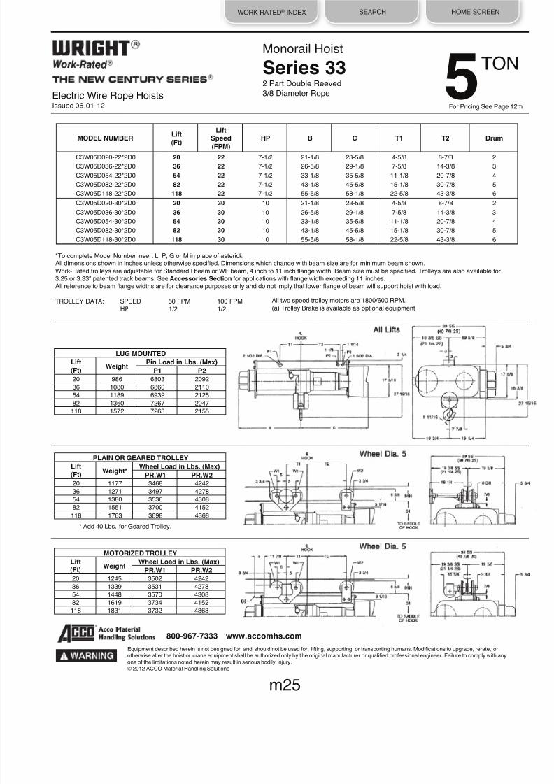
8/21/2019 2013 Wright Specifications Catalog
http://slidepdf.com/reader/full/2013-wright-specifications-catalog 74/189
WORK-RATED® INDEX SEARCH HOME SCREEN
* Add 40 Lbs. for Geared Trolley.
Monorail Hoist
Series 332 Part Double Reeved
3/8 Diameter Rope
All two speed trolley motors are 1800/600 RPM.
(a) Trolley Brake is available as optional equipment
LUG MOUNTED Lift
(Ft) Weight Pin Load in Lbs. (Max) P1 P2
20
986
6803
2092
36 1080 6860 2110
54
1189
6939
2125
82 1360 7267 2047
118
1572
7263
2155
PLAIN OR GEARED TROLLEY Lift(Ft) Weight* Wheel Load in Lbs. (Max)
PR.W1 PR.W2 20
1177
3468
4242
36 1271 3497 4278
54
1380
3536
4308
82 1551 3700 4152
118 1763 3698 4368
MOTORIZED TROLLEY Lift(Ft) Weight Wheel Load in Lbs. (Max)
PR.W1 PR.W2 20
1245
3502
4242
36 1339 3531 4278
54
1448
3570
4308
82 1619 3734 4152
118
1831
3732
4368
*To complete Model Number insert L, P, G or M in place of asterick.All dimensions shown in inches unless otherwise specified. Dimensions which change with beam size are for minimum beam shown.
Work-Rated trolleys are adjustable for Standard I beam or WF beam, 4 inch to 11 inch flange width. Beam size must be specified. Trolleys are also available for3.25 or 3.33" patented track beams. See Accessories Section for applications with flange width exceeding 11 inches.All reference to beam flange widths are for clearance purposes only and do not imply that lower flange of beam will support hoist with load.
TROLLEY DATA: SPEED 50 FPM 100 FPM
HP 1/2 1/2
Electric Wire Rope HoistsIssued 06-01-12
Equipment described herein is not designed for, and should not be used for, lifting, supporting, or transporting humans. Modifications to upgrade, rerate, orotherwise alter the hoist or crane equipment shall be authorized only by the original manufacturer or qualified professional engineer. Failure to comply with any
one of the limitations noted herein may result in serious bodily injury.© 2012 ACCO Material Handling Solutions
m25
800-967-7333 www.accomhs.com
MODEL NUMBER
Lift
(Ft)
Lift
Speed
(FPM) HP
B
C
T1
T2
Drum
C3W05D020-22*2D0 20 22
7-1/2
21-1/8
23-5/8
4-5/8
8-7/8
2
C3W05D036-22*2D0 36 22
7-1/2
26-5/8
29-1/8
7-5/8
14-3/8
3
C3W05D054-22*2D0 54 22 7-1/2 33-1/8 35-5/8 11-1/8 20-7/8 4
C3W05D082-22*2D0 82 22 7-1/2 43-1/8 45-5/8 15-1/8 30-7/8 5
C3W05D118-22*2D0 118 22
7-1/2
55-5/8
58-1/8
22-5/8
43-3/8
6
C3W05D020-30*2D0 20 30
10
21-1/8
23-5/8
4-5/8
8-7/8
2
C3W05D036-30*2D0 36 30
10
26-5/8
29-1/8
7-5/8
14-3/8
3
C3W05D054-30*2D0 54 30
10
33-1/8
35-5/8
11-1/8
20-7/8
4
C3W05D082-30*2D0 82 30 10 43-1/8 45-5/8 15-1/8 30-7/8 5
C3W05D118-30*2D0 118 30 10 55-5/8 58-1/8 22-5/8 43-3/8 6
TON5For Pricing See Page 12m

8/21/2019 2013 Wright Specifications Catalog
http://slidepdf.com/reader/full/2013-wright-specifications-catalog 75/189
WORK-RATED® INDEX SEARCH HOME SCREEN
* Add 40 Lbs. for Geared Trolley.
Electric Wire Rope HoistsIssued 06-01-12
Monorail Hoist
Series 342 Part Double Reeved
1/2 Diameter Rope
LUG MOUNTED Lift
(Ft) Weight Pin Load in Lbs. (Max) P1 P2
20
1890
6508
2691
31 2010 5994 3008
47
2170
6156
3007
76
2460
7498
2481
115 2850 8474 2188
PLAIN OR GEARED TROLLEY Lift(Ft) Weight* Wheel Load in Lbs. (Max)
PR.W1 PR.W2 20 2230 3374 5482
31
2350
3117
6116
47 2510 3198 6114
76
2800
3869
5062
115 3190 4357 4476
All two speed trolley motors are 1800/600 RPM.
(a) Trolley Brake is available as optional equipment
*To complete Model Number insert L, P, G or M in place of asterick.All dimensions shown in inches unless otherwise specified. Dimensions which change with beam size are for minimum beam shown.Work-Rated trolleys are adjustable for Standard I beam or WF beam, 4 inch to 11 inch flange width. Beam size must be specified. Trolleys are also available for3.25 or 3.33" patented track beams. See Accessories Section for applications with flange width exceeding 11 inches.All reference to beam flange widths are for clearance purposes only and do not imply that lower flange of beam will support hoist with load.
TROLLEY DATA: SPEED 50 FPM 100 FPMHP 1/2 1
MOTORIZED TROLLEY Lift(Ft) Weight Wheel Load in Lbs. (Max)
PR.W1 PR.W2 20
2298
3408
5482
31
2418
3151
6116
47 2578 3232 6114
76
2868
3903
5062
115 3258 4391 4476
Equipment described herein is not designed for, and should not be used for, lift ing, supporting, or transporting humans. Modifications to upgrade, rerate, orotherwise alter the hoist or crane equipment shall be authorized only by the original manufacturer or qualified professional engineer. Failure to comply with anyone of the limitations noted herein may result in serious bodily injury.© 2012 ACCO Material Handling Solutions
m26
800-967-7333 www.accomhs.com
MODEL NUMBER
Lift
(Ft)
Lift
Speed
(FPM) HP
B
C
T1
T2
Drum
C4W05D020-44*2D0 20 44
15
24-1/8
30-3/4
6
10-1/4
2
C4W05D031-44*2D0 31 44 15 28-5/8 35-1/4 11-3/8 14-3/4 3
C4W05D047-44*2D0 47 44 15 34-5/8 41-1/4 16 20-3/4 4
C4W05D076-44*2D0 76 44
15
45-5/8
52-1/4
16
31-3/4
5
C4W05D115-44*2D0 115 44
15
60-5/8
67-1/4
18
46-3/4
6
TON 5For Pricing See Page 12m

8/21/2019 2013 Wright Specifications Catalog
http://slidepdf.com/reader/full/2013-wright-specifications-catalog 76/189
WORK-RATED® INDEX SEARCH HOME SCREEN
* Add 40 Lbs. for Geared Trolley.
Electric Wire Rope HoistsIssued 06-01-12
Monorail Hoist
Series 334 Part Double Reeved
3/8 Diameter Rope
All two speed trolley motors are 1800/600 RPM.(a) Trolley Brake is available as optional equipment
LUG MOUNTED Lift(Ft) Weight Pin Load in Lbs. (Max)
P1 P2 22 1285 10946 2670
36
1465
11177
2644
54 1688 10952 2868
PLAIN OR GEARED TROLLEY Lift(Ft) Weight* Wheel Load in Lbs. (Max)
PR.W1 PR.W2 22
1634
5595
5446
36
1814
5710
5394
54 2037 5598 5842
MOTORIZED TROLLEY Lift
(Ft) Weight
Wheel Load in Lbs. (Max) PR.W1 PR.W2 22
1702
5629
5446
36 1882 5744 5394
54 2105 5632 5842
*To complete Model Number insert L, P, G or M in place of asterick.All dimensions shown in inches unless otherwise specified. Dimensions which change with beam size are for minimum beam shown.
Work-Rated trolleys are adjustable for Standard I beam or WF beam, 4 inch to 11 inch flange width. Beam size must be specified. Trolleys are also available for3.25 or 3.33" patented track beams. See Accessories Section for applications with flange width exceeding 11 inches.All reference to beam flange widths are for clearance purposes only and do not imply that lower flange of beam will support hoist with load.
TROLLEY DATA: SPEED 50 FPM 100 FPMHP 1/2 1
Equipment described herein is not designed for, and should not be used for, lifting, supporting, or transporting humans. Modifications to upgrade, rerate, orotherwise alter the hoist or crane equipment shall be authorized only by the original manufacturer or qualified professional engineer. Failure to comply with anyone of the limitations noted herein may result in serious bodily injury.© 2012 ACCO Material Handling Solutions
m27
800-967-7333 www.accomhs.com
MODEL NUMBER
Lift (Ft)
Lift
Speed
(FPM) HP
B
C
T1
T2
Drum
C3W07D022-15*4D0 22 15 7-1/2 33-1/8 35-5/8 9-1/8 20-7/8 4
C3W07D036-15*4D0 36 15 7-1/2 43-1/8 45-5/8 13-1/8 30-7/8 5
C3W07D054-15*4D0 54 15
7-1/2
55-5/8
58-1/8
20-5/8
43-3/8
6
C3W07D022-22*4D0 22 22 10 33-1/8 35-5/8 9-1/8 20-7/8 4
C3W07D036-22*4D0 36 22
10
43-118
45-5/8
13-1/8
30-7/8
5
C3W07D054-22*4D0 54 22
10
55-5/8
58-1/8
20-5/8
43-3/8
6
For Pricing See Page 13m
TON71
2

8/21/2019 2013 Wright Specifications Catalog
http://slidepdf.com/reader/full/2013-wright-specifications-catalog 77/189
WORK-RATED® INDEX SEARCH HOME SCREEN
* Add 40 Lbs. for Geared Trolley.
Electric Wire Rope HoistsIssued 06-01-12
Monorail Hoist
Series 342 Part Double Reeved
1/2 Diameter Rope
LUG MOUNTED Lift
(Ft) Weight Pin Load in Lbs. (Max) P1 P2
20 1890 9662 3614
31
2010
8818
4096
47 2170 8980 4095
76 2460 10822 3319
115
2850
12084
2883
PLAIN OR GEARED TROLLEY Lift(Ft) Weight* Wheel Load in Lbs. (Max)
PR.W1 PR.W2 20 2230 4951 7328
31
2350
4529
8292
47 2510 4610 8290
76
2800
5531
6738
115 3190 6162 5866
All two speed trolley motors are 1800/600 RPM.
(a) Trolley Brake is available as optional equipment
*To complete Model Number insert L, P, G or M in place of asterick.All dimensions shown in inches unless otherwise specified. Dimensions which change with beam size are for minimum beam shown.Work-Rated trolleys are adjustable for Standard I beam or WF beam, 4 inch to 11 inch flange width. Beam size must be specified. Trolleys are also available for3.25 or 3.33" patented track beams. See Accessories Section for applications with flange width exceeding 11 inches.All reference to beam flange widths are for clearance purposes only and do not imply that lower flange of beam will support hoist with load.
TROLLEY DATA: SPEED 50 FPM 100 FPM
HP 1/2 1
MOTORIZED TROLLEY Lift
(Ft) Weight Wheel Load in Lbs. (Max) PR.W1 PR.W2
20 2298 4985 7328
31
2418
4563
8292
47 2578 4644 8290
76
2868
5565
6738
115
3258
6196
5866
MODEL NUMBER
Lift
(Ft)
Lift
Speed
(FPM) HP
B
C
T1
T2
Drum
C4W07D020-30*2D0 20 30 15 24-1/8 30-3/4 6 10-1/4 2
C4W07D031-30*2D0 31 30 15 28-5/8 35-1/4 11-3/8 14-3/4 3
C4W07D047-30*2D0 47 30 15 34-5/8 41-1/4 16 20-3/4 4
C4W07D076-30*2D0 76 30
15
45-5/8
52-1/4
16
31-3/4
5
C4W07D115-30*2D0 115 30
15
60-5/8
67-1/4
18
46-3/4
6
Equipment described herein is not designed for, and should not be used for, lifting, supporting, or transporting humans. Modifications to upgrade, rerate, orotherwise alter the hoist or crane equipment shall be authorized only by the original manufacturer or qualified professional engineer. Failure to comply with anyone of the limitations noted herein may result in serious bodily injury.© 2012 ACCO Material Handling Solutions
m28
800-967-7333 www.accomhs.com
For Pricing See Page 13m
TON 71
2

8/21/2019 2013 Wright Specifications Catalog
http://slidepdf.com/reader/full/2013-wright-specifications-catalog 78/189
WORK-RATED® INDEX SEARCH HOME SCREEN
* Add 40 Lbs. for Geared Trolley.
Electric Wire Rope HoistsIssued 06-01-12
Monorail Hoist
Series 352 Part Double Reeved
1/2 Diameter Rope
LUG MOUNTED Lift
(Ft) Weight Pin Load in Lbs. (Max) P1 P2
24
2440
9986
7454
38 2744 11600 3072
57 3018 11934 3042
85
3454
12328
3063
124 4110 12716 3197
PLAIN OR GEARED TROLLEY
Lift
(Ft) Weight* Wheel Load in Lbs. (Max) PR.W1 PR.W2
24
2982
6026
5978
38 3110 5927 6256
57 3384 6094 6196
85
3820
6291
6238
124 4476 6485 6506
MOTORIZED TROLLEY Lift(Ft) Weight Wheel Load in Lbs. (Max)
PR.W1 PR.W2 24 3082 6026 6028
38
3210
5977
6256 57 3484 6144 6196
85
3920
6341
6238
124
4576
6535
6506
MODEL NUMBER Lift(Ft)
Lift
Speed(FPM)
HP B C Lug Mounted
Trolley Mounted
DrumT1 T2 T1 T2
C5W07D024-44*2D0 24 44 20 24-1/2 32 6-1/2 11 31-5/8 17-3/8 2
C5W07D038-44*2D0 38 44 20 29 36-7/16 6 14-1/2 6 14-1/2 3
C5W07D057-44*2D0 57 44
20
35
42-7/16
8-1/2
20-1/2
8-1/2
20-1/2
4
C5W07D085-44*2D0 85 44
20
44
51-7/16
12-1/2
29-1/2
12-1/2
29-1/2
5
C5W07D124-44*2D0 124 44 20 56-1/2 64 19 42 19 42 6
All two speed trolley motors are 1800/600 RPM.(a) Trolley Brake is available as optional equipment
*To complete Model Number insert L, P, G or M in place of asterick.All dimensions shown in inches unless otherwise specified. Dimensions which change with beam size are for minimum beam shown.Work-Rated trolleys are adjustable for Standard I beam or WF beam, 4 inch to 11 inch flange width. Beam size must be specified. Trolleys are also available for3.25 or 3.33" patented track beams. See Accessories Section for applications with flange width exceeding 11 inches.
All reference to beam flange widths are for clearance purposes only and do not imply that lower flange of beam will support hoist with load.
TROLLEY DATA: SPEED 50 FPM 100 FPMHP 1/2 1
Equipment described herein is not designed for, and should not be used for, lift ing, supporting, or transporting humans. Modifications to upgrade, rerate, orotherwise alter the hoist or crane equipment shall be authorized only by the original manufacturer or qualified professional engineer. Failure to comply with anyone of the limitations noted herein may result in serious bodily injury.© 2012 ACCO Material Handling Solutions
m29
800-967-7333 www.accomhs.com
For Pricing See Page 13
TON71
2

8/21/2019 2013 Wright Specifications Catalog
http://slidepdf.com/reader/full/2013-wright-specifications-catalog 79/189
WORK-RATED® INDEX SEARCH HOME SCREEN
* Add 40 Lbs. for Geared Trolley.
PLAIN OR GEARED TROLLEY
Lift(Ft) Weight* Wheel Load in Lbs. (Max)
PR.W1 PR.W2 22 1634 7330 6966
36
1814
7464
6886
54 2037 7292 7454
Electric Wire Rope HoistsIssued 06-01-12
Monorail Hoist
Series 334 Part Double Reeved
3/8 Diameter Rope
LUG MOUNTED Lift
(Ft) Weight Pin Load in Lbs. (Max) P1 P2
22 1285 14425 3430
36
1465
14685
3390
54 1688 14341 3674
All two speed trolley motors are 1800/600 RPM.(a) Trolley Brake is available as optional equipment
*To complete Model Number insert L, P, G or M in place of asterick.All dimensions shown in inches unless otherwise specified. Dimensions which change with beam size are for minimum beam shown.Work-Rated trolleys are adjustable for Standard I beam or WF beam, 4 inch to 11 inch flange width. Beam size must be specified. Trolleys are also available for3.25 or 3.33" patented track beams. See Accessories Section for applications with flange width exceeding 11 inches.
All reference to beam flange widths are for clearance purposes only and do not imply that lower flange of beam will support hoist with load.
TROLLEY DATA: SPEED 50 FPM 100 FPMHP 1/2 1
MOTORIZED TROLLEY Lift(Ft) Weight Wheel Load in Lbs. (Max)
PR.W1 PR.W2 22
1702
7364
6966
36 1882 7498 6886
54
2105
7326
7454
MODEL NUMBER
Lift
(Ft)
Lift
Speed
(FPM) HP
B
C
T1
T2
Drum
C3W10D022-15*4D0 22 15
10
33-1/8
35-5/8
9-1/8
20-7/8
4
C3W10D036-15*4D0 36 15 10 43-1/8 45-5/8 13-1/8 30-7/8 5
C3W10D054-15*4D0 54 15 10 55-5/8 58-1/8 20-5/8 43-3/8 6
Equipment described herein is not designed for, and should not be used for, lifting, supporting, or transporting humans. Modifications to upgrade, rerate, orotherwise alter the hoist or crane equipment shall be authorized only by the original manufacturer or qualified professional engineer. Failure to comply with anyone of the limitations noted herein may result in serious bodily injury.© 2012 ACCO Material Handling Solutions
m30
800-967-7333 www.accomhs.com
TON 10For Pricing See Page 14m

8/21/2019 2013 Wright Specifications Catalog
http://slidepdf.com/reader/full/2013-wright-specifications-catalog 80/189
WORK-RATED® INDEX SEARCH HOME SCREEN
* Add 40 Lbs. for Geared Trolley.
Electric Wire Rope HoistsIssued 06-01-12
Monorail Hoist
Series 344 Part Double Reeved
1/2 Diameter Rope
All two speed trolley motors are 1800/600 RPM.(a) Trolley Brake is available as optional equipment
LUG MOUNTED Lift(Ft) Weight Pin Load in Lbs. (Max)
P1 P2 20 2430 10271 12159
35
2750
10598
12152
54
3250
10903
12347
PLAIN OR GEARED TROLLEY Lift(Ft) Weight* Wheel Load in Lbs. (Max)
PR.W1 PR.W2 20 2910 5256 6200
35
3230
5419
6196
54 3730 5572 6294
MOTORIZED TROLLEY Lift
(Ft) Weight Wheel Load in Lbs. (Max) PR.W1 PR.W2
20
2978
5256
6234
35 3298 5419 6230
54
3798
5572
6328
*To complete Model Number insert L, P, G or M in place of asterick.All dimensions shown in inches unless otherwise specified. Dimensions which change with beam size are for minimum beam shown.
Work-Rated trolleys are adjustable for Standard I beam or WF beam, 4 inch to 11 inch flange width. Beam size must be specified. Trolleys are also available for3.25 or 3.33" patented track beams. See Accessories Section for applications with flange width exceeding 11 inches.All reference to beam flange widths are for clearance purposes only and do not imply that lower flange of beam will support hoist with load.
TROLLEY DATA: SPEED 50 FPM 100 FPM
HP 1/2 1
MODEL NUMBER
Lift (Ft)
Lift
Speed
(FPM) HP
B
C
T1
T2
Drum
C4W10D020-22*4D0 20 22
15
34-5/8
41-1/4
14
14
4
C4W10D035-22*4D0 35 22 15 45-5/8 52-1/4 24 24 5
C4W10D054-22*4D0 54 22 15 60-5/8 67-1/4 36 36 6
Equipment described herein is not designed for, and should not be used for, lifting, supporting, or transporting humans. Modifications to upgrade, rerate, orotherwise alter the hoist or crane equipment shall be authorized only by the original manufacturer or qualified professional engineer. Failure to comply with anyone of the limitations noted herein may result in serious bodily injury.© 2012 ACCO Material Handling Solutions
m31
800-967-7333 www.accomhs.com
TON10For Pricing See Page 14

8/21/2019 2013 Wright Specifications Catalog
http://slidepdf.com/reader/full/2013-wright-specifications-catalog 81/189
WORK-RATED® INDEX SEARCH HOME SCREEN
* Add 40 Lbs. for Geared Trolley.
PLAIN OR GEARED TROLLEY Lift(Ft) Weight* Wheel Load in Lbs. (Max)
PR.W1 PR.W2 24
2982
7798
7592
38 3110 7695 7720
57
3384
7859
7666
85
3820
8047
7726
124
4476
8225
8026
Electric Wire Rope HoistsIssued 06-01-12
Monorail Hoist
Series 352 Part Double Reeved
1/2 Diameter Rope
LUG MOUNTED Lift(Ft) Weight Pin Load in Lbs. (Max)
P1 P2 24
2440
13131
9309
38 2744 15136 3804
57 3018 15464 3777
85 3454 15840 3807
124
4110
16196
3957
MOTORIZED TROLLEY Lift(Ft) Weight Wheel Load in Lbs. (Max)
PR.W1 PR.W2 24 3082 7798 7642
38
3210
7745
7720
57
3484
7909
7666
85
3920
8097
7726
124
4576
8275
8026
All two speed trolley motors are 1800/600 RPM.(a) Trolley Brake is available as optional equipment
*To complete Model Number insert L, P, G or M in place of asterick.All dimensions shown in inches unless otherwise specified. Dimensions which change with beam size are for minimum beam shown.Work-Rated trolleys are adjustable for Standard I beam or WF beam, 4 inch to 11 inch flange width. Beam size must be specified. Trolleys are also available for3.25 or 3.33" patented track beams. See Accessories Section for applications with flange width exceeding 11 inches.
All reference to beam flange widths are for clearance purposes only and do not imply that lower flange of beam will support hoist with load.
TROLLEY DATA: SPEED 50 FPM 100 FPMHP 1/2 1
Equipment described herein is not designed for, and should not be used for, lifting, supporting, or transporting humans. Modifications to upgrade, rerate, orotherwise alter the hoist or crane equipment shall be authorized only by the original manufacturer or qualified professional engineer. Failure to comply with anyone of the limitations noted herein may result in serious bodily injury.
© 2012 ACCO Material Handling Solutions
m32
800-967-7333 www.accomhs.com
MODEL NUMBER Lift(Ft)
Lift
Speed(FPM)
HP B C Lug Mounted
Trolley Mounted
DrumT1 T2 T1 T2
C5W10D024-30*2D0
24
30
20
24-1/2
32
6-1/2
11
31-5/8
17-3/8
2
C5W10D038-30*2D0 38 30 20 29 36-7/16 6 14-1/2 6 14-1/2 3
C5W10D057-30*2D0 57 30 20 35 42-7/16 8-1/2 20-1/2 8-1/2 20-1/2 4
C5W10D085-30*2D0
85
30
20
44
51-7/16
12-1/2
29-1/2
12-1/2
29-1/2
5
C5W10D124-30*2D0 124 30 20 56-1/2 64 19 42 19 42 6
TON 10For Pricing See Page 14m

8/21/2019 2013 Wright Specifications Catalog
http://slidepdf.com/reader/full/2013-wright-specifications-catalog 82/189
WORK-RATED® INDEX SEARCH HOME SCREEN
* Add 40 Lbs. for Geared Trolley.
Electric Wire Rope HoistsIssued 06-01-12
Monorail Hoist
Series 344 Part Double Reeved
1/2 Diameter Rope
All two speed trolley motors are 1800/600 RPM.(a) Trolley Brake is available as optional equipment
LUG MOUNTED Lift
(Ft) Weight Pin Load in Lbs. (Max) P1 P2
20 2430 15271 17159
35 2750 15598 17152
54 3250 15903 17347
PLAIN OR GEARED TROLLEY Lift(Ft) Weight* Wheel Load in Lbs. (Max)
PR.W1 PR.W2 20 2910 7756 8700
35
3230
7919
8696
54
3730
8072
8794
MOTORIZED TROLLEY Lift(Ft) Weight Wheel Load in Lbs. (Max)
PR.W1 PR.W2 20 2978 7756 8734
35
3298
7919
8730
54
3798
8072
8828
*To complete Model Number insert L, P, G or M in place of asterick.All dimensions shown in inches unless otherwise specified. Dimensions which change with beam size are for minimum beam shown.
Work-Rated trolleys are adjustable for Standard I beam or WF beam, 4 inch to 11 inch flange width. Beam size must be specified. Trolleys are also available for3.25 or 3.33" patented track beams. See Accessories Section for applications with flange width exceeding 11 inches.All reference to beam flange widths are for clearance purposes only and do not imply that lower flange of beam will support hoist with load.
TROLLEY DATA: SPEED 50 FPM 100 FPM
HP 1 1 (2 REQUIRED)
MODEL NUMBER
Lift (Ft)
Lift
Speed (FPM)
HP
B
C
T1
T2
Drum
C4W15D020-15*4D0 20 15
15
34-5/8
41-1/4
14
14
4
C4W15D035-15*4D0 35 15
15
45-5/8
52-1/4
24
24
5
C4W15D054-15*4D0 54 15 15 60-5/8 67-1/4 36 36 6
Equipment described herein is not designed for, and should not be used for, lifting, supporting, or transporting humans. Modifications to upgrade, rerate, orotherwise alter the hoist or crane equipment shall be authorized only by the original manufacturer or qualified professional engineer. Failure to comply with any
one of the limitations noted herein may result in serious bodily injury.© 2012 ACCO Material Handling Solutions
m33
800-967-7333 www.accomhs.com
TON15For Pricing See Page 15

8/21/2019 2013 Wright Specifications Catalog
http://slidepdf.com/reader/full/2013-wright-specifications-catalog 83/189
WORK-RATED® INDEX SEARCH HOME SCREEN
* Add 40 Lbs. for Geared Trolley.
PLAIN OR GEARED TROLLEY Lift(Ft) Weight*
Wheel Load in Lbs. (Max) PR.W1 PR.W2
24 3796 8034 8864
39 4304 8305 8847
58
4978
8551
8938
Electric Wire Rope HoistsIssued 06-01-12
Monorail Hoist
Series 354 Part Double Reeved
1/2 Diameter Rope
LUG MOUNTED Lift
(Ft) Weight Pin Load in Lbs. (Max) P1 P2
24
3288
15814
17474
39 3796 16356 17440
58 4470 16848 17622
MOTORIZED TROLLEY Lift
(Ft) Weight Wheel Load in Lbs. (Max)
PR.W1 PR.W2 24
3896
8034
8914
39
4404
8305
8897
58 5078 8551 8988
All two speed trolley motors are 1800/600 RPM.
(a) Trolley Brake is available as optional equipment
*To complete Model Number insert L, P, G or M in place of asterick.All dimensions shown in inches unless otherwise specified. Dimensions which change with beam size are for minimum beam shown.
Work-Rated trolleys are adjustable for Standard I beam or WF beam, 4 inch to 11 inch flange width. Beam size must be specified. Trolleys are also available for3.25 or 3.33" patented track beams. See Accessories Section for applications with flange width exceeding 11 inches.All reference to beam flange widths are for clearance purposes only and do not imply that lower flange of beam will support hoist with load.
TROLLEY DATA: SPEED 50 FPM 100 FPM
HP 1 1 (2 REQUIRED)
MODEL NUMBER
Lift (Ft)
Lift
Speed (FPM)
HP
B
C
T1
T2
Drum
C5W15D024-22*4D0 24 22 20 34-7/8 42-7/16 14 14 4
C5W15D039-22*4D0 39 22
20
43-7/8
51-7/16
23
23
5
C5W15D058-22*4D0 58 22
20
56-3/8
64
32-1/2
32-1/2
6
Equipment described herein is not designed for, and should not be used for, lifting, supporting, or transporting humans. Modifications to upgrade, rerate, orotherwise alter the hoist or crane equipment shall be authorized only by the original manufacturer or qualified professional engineer. Failure to comply with anyone of the limitations noted herein may result in serious bodily injury.© 2012 ACCO Material Handling Solutions
m34
800-967-7333 www.accomhs.com
TON 15For Pricing See Page 15m

8/21/2019 2013 Wright Specifications Catalog
http://slidepdf.com/reader/full/2013-wright-specifications-catalog 84/189
WORK-RATED® INDEX SEARCH HOME SCREEN
* Add 40 Lbs. for Geared Trolley.
Electric Wire Rope HoistsIssued 06-01-12
Monorail Hoist
Series 354 Part Double Reeved
1/2 Diameter Rope
All two speed trolley motors are 1800/600 RPM.(a) Trolley Brake is available as optional equipment
LUG MOUNTED Lift(Ft) Weight Pin Load in Lbs. (Max)
P1 P2 24
3288
20814
22474
39 3796 21356 22440
58 4470 21848 22622
PLAIN OR GEARED TROLLEY Lift(Ft) Weight* Wheel Load in Lbs. (Max)
PR.W1 PR.W2 24 3796 10534 11364
39
4304
10805
11347
58 4978 11051 11438
MOTORIZED TROLLEY Lift(Ft) Weight Wheel Load in Lbs. (Max)
PR.W1 PR.W2 24
3896
10534
11414
39 4404 10805 11397
58
5078
11051
11488
*To complete Model Number insert L, P, G or M in place of asterick.All dimensions shown in inches unless otherwise specified. Dimensions which change with beam size are for minimum beam shown.
Work-Rated trolleys are adjustable for Standard I beam or WF beam, 4 inch to 11 inch flange width. Beam size must be specified. Trolleys are also available for3.25 or 3.33" patented track beams. See Accessories Section for applications with flange width exceeding 11 inches.All reference to beam flange widths are for clearance purposes only and do not imply that lower flange of beam will support hoist with load.
TROLLEY DATA: SPEED 50 FPM 100 FPM
HP 1 1 (2 REQUIRED)
MODEL NUMBER
Lift (Ft)
Lift
Speed
(FPM) HP
B
C
T1
T2
Drum
C5W20D024-15*4D0 24 15
20
34-7/8
42-7/16
14
14
4
C5W20D039-15*4D0 39 15 20 43-7/8 51-7/16 23 23 5
C5W20D058-15*4D0 58 15 20 56-3/8 64 32-1/2 32-1/2 6
Equipment described herein is not designed for, and should not be used for, lifting, supporting, or transporting humans. Modifications to upgrade, rerate, orotherwise alter the hoist or crane equipment shall be authorized only by the original manufacturer or qualified professional engineer. Failure to comply with anyone of the limitations noted herein may result in serious bodily injury.© 2012 ACCO Material Handling Solutions
m35
800-967-7333 www.accomhs.com
TON20For Pricing See Page 16

8/21/2019 2013 Wright Specifications Catalog
http://slidepdf.com/reader/full/2013-wright-specifications-catalog 85/189
WORK-RATED® INDEX SEARCH HOME SCREEN
Electric Wire Rope HoistsIssued 06-01-12
Monorail Hoist
Series 354 Part Double Reeved
9/16 Diameter Rope
All two speed trolley motors are 1800/600 RPM.(a) Trolley Brake is available as optional equipment
*To complete Model Number insert L, P or M in place of asterick.All dimensions shown in inches unless otherwise specified. Dimensions which change with beam size are for minimum beam shown.Work-Rated trolleys are adjustable for Standard I beam or WF beam, 4 inch to 11 inch flange width. Beam size must be specified. Trolleys are also available for3.25 or 3.33" patented track beams. See Accessories Section for applications with flange width exceeding 11 inches.All reference to beam flange widths are for clearance purposes only and do not imply that lower flange of beam will support hoist with load.
TROLLEY DATA: SPEED 50 FPM 100 FPM
HP 1/2 (2 REQUIRED) 1 (2 REQUIRED)
MODEL NUMBER
Lift (Ft)
Lift
Speed
(FPM) HP
B
C
T1
T2
Drum
C5W25D020-12L4D0 20 12 20 35-7/8 43-1/4 19-11/16 19-11/16 4
C5W25D032-12*4D0 32 12 20 44-7/8 52-1/4 24-9/16 27-7/16 5
C5W25D048-12*4D0 48 12
20
57-3/8
64-3/4
24-9/16
27-7/16
6
Equipment described herein is not designed for, and should not be used for, lifting, supporting, or transporting humans. Modifications to upgrade, rerate, orotherwise alter the hoist or crane equipment shall be authorized only by the original manufacturer or qualified professional engineer. Failure to comply with anyone of the limitations noted herein may result in serious bodily injury.© 2012 ACCO Material Handling Solutions
m36
800-967-7333 www.accomhs.com
TON 25For Pricing See Page 17m
LUG MOUNTED
Lift(Ft)
Weight Pin Load in Lbs.
(Max)
P1 P2
20 3680 25927 27753
32 4027 27956 26071
48
4522
28141
26381
PLAIN TROLLEY
Lift(Ft)
Weight* Wheel Load in Lbs. (Max)
PR.W1 PR.W2
32 6042 7357 6653
48
6826
7548
6658
MOTORIZED TROLLEY
Lift
(Ft) Weight
Wheel Load in Lbs. (Max)
PR.W1 PR.W2 PR.W3
32 6142 7357 6703 6653
48 6926 7548 6708 6658
All Lifts
Wheel Dia. 6
Wheel Dia. 6

8/21/2019 2013 Wright Specifications Catalog
http://slidepdf.com/reader/full/2013-wright-specifications-catalog 86/189
WORK-RATED® INDEX SEARCH HOME SCREEN
Equipment described herein is not designed for, and should not be used for, lifting, supporting, or transporting humans. Modifications to upgrade, rerate, orotherwise alter the hoist or crane equipment shall be authorized only by the original manufacturer or qualified professional engineer. Failure to comply with anyone of the limitations noted herein may result in serious bodily injury.© 2012 ACCO Material Handling Solutions
800-967-7333 www.accomhs.com
Electric Wire Rope HoistsIssued 06-01-12
Wright family of Work-Rated hoists is a complete line of electric wire rope
hoists. It is an advanced design incorporating the most recent materialsand concept. The most current duty cycle and safety requirements of
users are built into this line, not added on.
CONSTRUCTION FEATURES:
CONTROLS: Choose from single, 2-speed, or inverter. Controls are
magnetic reversing type, mechanically and electrically interlocked with115 volt control circuit. All wiring conforms to applicable NEC
requirements. Motor thermostats are standard providing motor runningovercurrent protection. NEMA Type 3R enclosures are standard. Cover is
lightweight, tough ABS material, deep-drawn for maximum controlaccessibility.
PUSH BUTTON STATION: Push button stations are not furnished as
standard equipment with these hoists. Push button station drop of cord &strain chain are available as optional equipment. See Accessories
Section. Specify required drop.
MOTOR: Standard NEMA C face mounting, TENV, Class F insulation,
30-minute duty motor is provided for standard commercial power supplies.The motor has a standard NEMA shaft extension.
GEAR TRAIN: Quiet, helical and spur gearing. All gears are machine cut,
case-hardened alloy steel with shock-resistant ductile cores. Gearing isdesigned to AGMA standards for maximum life, and operates in an oil
bath. Rugged aluminum alloy housing provides rapid heat dissipation.
BEARINGS - SPIDER RETAINERS: Precision heavy-duty ball bearings
support all shafts. All bearings are either splash lubricated, or lifetimepre-lubricated and sealed. Bearings at outboard end of shafts are held in
place by heavy-duty Spider Retainers. This allows removal of GearHousing Cover for inspection (after draining oil). All internal parts remain
in place and can be operated for inspection.
DRUM: The large diameter steel drum has machined grooves and largeflanges. At least two full turns of rope remain on the drum at the lowest
hook position of rated lift.
LOAD BLOCK - HOOK: Drop forged heat-treated steel hook swivels 360˚
on a shielded roller thrust bearing and comes equipped with a spring
latch. Work can be performed on the load block without removing wirerope from drum. Sheaves are machined steel.
WIRE ROPE: Pre-formed wire rope, of hoisting service construction,
made of extra improved plow steel (XIP) with an independent wire ropecenter. Has swaged fittings on both ends for ease of replacement if
necessary.
MECHANICAL LOAD BRAKE: Automatic Weston-type multiple discbrake can hold a full capacity load independent of motor brake. This brake
assures that load does not accelerate while being lowered. No wear
compensation adjustment is required.
MOTOR BRAKE: Proven in millions of hours of in-service operation, the
original Wright rectified D-C magnet-actuated disc brake delivers rapidstops with virtually no hook drift. Rated a minimum of 150% of full loadmotor torque. Exclusive brake-sensing microswitch prevents motor from
operating against engaged brake and when brake requires adjustment.
LIMIT SWITCH: A gravity-type upper hook travel limit switch is provided.The unit is equipped with an automatic momentary lowering circuit. An
optional geared limit switch is also available.
OVERLOAD CUTOFF: Exclusive patented ACCO unit is standard on allWork-Rated hoists except single-line models. The overload limiting devic
shall be designed to permit operation of the hoist within its rated load andlimit the amount of overload that can be lifted by a properly maintained
hoist, under normal operating conditions.
The overload limiting device may allow the lifting of an overload, but shalbe designed to prevent the lifting of an overload of such magnitude that
could cause damage to a hoist, trolley, or supports. This does not imply tany overload is to be intentionally applied to the hoist.
The overload limiting device is an emergency device and shall not be use
to measure the maximum load to be lifted and shall not be used to sensethe overload imposed by the constrained load.
TROLLEY FRAME: The trolley frame shall be built of steel and precision
machined to assure proper alignment of trolley wheels and drives.
TROLLEY WHEELS: Trolley wheels shall have tread surfaces machined
and hardened to 375-425 Brinell. Each wheel shall be supported on anti-friction bearings suitable to take radial and thrust loads. The wheels shal
be lubricated at the factory with a sodium base grease. The trolley wheelhave dual tread for operation on tapered or f lat flange beams. Wheel trea
shall be smooth, true and uniform within .010 inch tread diameter on allwheels.
TROLLEY DRIVE: The trolley drive shall be a right angle worm gear
reducer fully enclosed with a steel worm and bronze worm wheel designeto AGMA standards. The final reduction gear reduction at trolley wheels
be spur gears and will be open. The trolley drive motor shall be TENV 30minute duty with class F insulation and NEMA C face mounting. A spring
set A.C. disc type brake is available as optional equipment.
TROLLEY CONTROLS: Choose from single, 2-speed, or inverter. Singleand 2-speed controls are available with ACM solid state cushion start for
smooth travel motion and excellent load control as optional equipment.
Monorail HoistCLOSE HEADROOM CROSS MOUNTED
Features & Benefits
1TO 10 TON

8/21/2019 2013 Wright Specifications Catalog
http://slidepdf.com/reader/full/2013-wright-specifications-catalog 87/189
WORK-RATED® INDEX SEARCH HOME SCREEN
Equipment described herein is not designed for, and should not be used for, lifting, supporting, or transporting humans. Modifications to upgrade, rerate, orotherwise alter the hoist or crane equipment shall be authorized only by the original manufacturer or qualified professional engineer. Failure to comply with anyone of the limitations noted herein may result in serious bodily injury.© 2012 ACCO Material Handling Solutions
800-967-7333 www.accomhs.com
Electric Wire Rope HoistsIssued 06-01-12
1TO 10 TON Monorail HoistCLOSE HEADROOM CROSS MOUNTED
Features & Benefits
HOW TO SPECIFY A Work-Rated HOIST
1. DETERMINE THE CAPACITY, LIFTING SPEED AND LIFTING
DISTANCE.
2. DETERMINE THE REEVING REQUIRED FOR YOUR
APPLICATION. Work-Rated hoists may be reeved in various ways to
gain desired mechanical advantages ... capacity, lifting distance, and
lifting speeds.
3. SPECIFY PROPER MODEL NUMBER in regard to hoist.
Capacity, lifting speed, mounting and hoist control found in the
following pages.
4. SPECIFY MOTOR VOLTAGE: Wright standard motors are
available in 200/230/460/575-3-60 power with Class F insulation,
and are totally enclosed non-ventilated. Control is furnished as
standard equipment. Additional motor and control accessories are
found in the Accessories Section.
5. SPECIFY BEAM FLANGE WIDTH: Work-Rated trolleys are
adjustable for Standard I beam or WF beam, 4 inch to 11 inch
flange width. Beam size must be specified. Trolleys are also
available for 3.25 or 3.33" patented track beams. Trolleys for WF
beams with flange widths greater than 11 inches available. See
Accessories. All reference to beam flange widths are for clearance
purposes only and do not imply that lower flange of beam will
support hoist with load.
6. SPECIFY OTHER MODIFICATIONS AND ACCESSORIES.
7. SPECIAL APPLICATION HOISTS: Contact your nearest
Wright representative.
8. FOR CURVED TRACK APPLICATION, CONTACT FACTORY.
9. ACCO RESERVES THE RIGHT TO MAKE CHANGES TO
THIS CATALOG AS MAY BE DEEMED NECESSARY.

8/21/2019 2013 Wright Specifications Catalog
http://slidepdf.com/reader/full/2013-wright-specifications-catalog 88/189
WORK-RATED® INDEX SEARCH HOME SCREEN
Monorail HoistCLOSE HEADROOM CROSS MOUNTED
Series 322 Part Double Reeved
3/8 Diameter Rope
All dimensions shown in inches unless otherwise specified. Dimensions which change with beam size are for minimum beam shown.Speedway trolleys are adjustable for Standard I beam or WF beam, 4 inch to 11 inch flange width. Beam size must be specified. Trolleys are also available for3.25 or 3.33" patented track beams. See Accessories Section for applications with flange width exceeding 11 inches.
All reference to beam flange widths are for clearance purposes only and do not imply that lower flange of beam will support hoist with load.
TROLLEY DATA: Speed 50 FPM 100 FPMHP 1/2 1/2
LUG MOUNTED
Lift(Ft)
WeightPin Load in Lbs. (Max)
P1 P2
20 1090 1492 1598
36 1223 1493 1730
60 1423 1528 1895
PLAIN TROLLEY
Lift(Ft)
Weight
Wheel Load in Lbs.(Max)
PR.W1 PR.W2
20
1282
794
847
36
1414
794
913
60 1614 812 995
MOTORIZED TROLLEY
Lift(Ft)
Weight
Wheel Load in Lbs.(Max)
PR.W1 PR.W2
20 1348 827 847
36 1480 827 913
60 1680 845 995
x1
Equipment described herein is not designed for, and should not be used for, lifting, supporting, or transporting humans. Modifications to upgrade, rerate, orotherwise alter the hoist or crane equipment shall be authorized only by the original manufacturer or qualified professional engineer. Failure to comply with anyone of the limitations noted herein may result in serious bodily injury.© 2012 ACCO Material Handling Solutions
800-967-7333 www.accomhs.com
MODEL NUMBER Lift(Ft)
Single Speed Two Speed
C DrumFPM B HP FPM B HP
X2W01D020-15*2D0 20 15 31-3/4 3 15 / 5 34-5/8 3 / 1 25-7/8 4
X2W01D036-15*2D0 36 15
39-1/4
3 15 / 5
42-1/8
3 / 1
33-3/8
6
X2W01D060-15*2D0 60 15
50-3/8
3 15 / 5
53-1/4
3 / 1
44-1/2
7
X2W01D020-22*2D0 20 22
33-1/8
3 22 / 7
37-1/8
5 / 1.67
25-7/8
4
X2W01D036-22*2D0 36 22 40-5/8 3 22 / 7 44-5/8 5 / 1.67 33-3/8 6
X2W01D060-22*2D0 60 22 51-3/4 3 22 / 7 55-3/4 5 / 1.67 44-1/2 7
X2W01D020-30*2D0 20 30 33-1/8 3 30 / 10 37-1/8 5 / 1.67 25-7/8 4
X2W01D036-30*2D0 36 30 40-5/8 3 30 / 10 44-5/8 5 / 1.67 33-3/8 6
X2W01D060-30*2D0 60 30 51-3/4 3 30 / 10 55-3/4 5 / 1.67 44-1/2 7
TON1For Pricing See Page 1x
Electric Wire Rope HoistsIssued 06-01-12
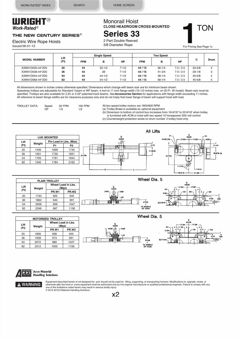
8/21/2019 2013 Wright Specifications Catalog
http://slidepdf.com/reader/full/2013-wright-specifications-catalog 89/189
WORK-RATED® INDEX SEARCH HOME SCREEN
Electric Wire Rope HoistsIssued 06-01-12
Monorail HoistCLOSE HEADROOM CROSS MOUNTED
Series 332 Part Double Reeved
3/8 Diameter Rope
All dimensions shown in inches unless otherwise specified. Dimensions which change with beam size are for minimum beam shown.Speedway trolleys are adjustable for Standard I beam or WF beam, 4 inch to 11 inch flange width (10-1/2 inches max. on 20 Ft. lift model). Beam size must bespecified. Trolleys are also available for 3.25 or 3.33" patented track beams. See Accessories Section for applications with flange width exceeding 11 inches.All reference to beam flange widths are for clearance purposes only and do not imply that lower flange of beam will support hoist with load.
TROLLEY DATA: Speed 50 FPM 100 FPMHP 1/2 1/2
PLAIN TROLLEY
Lift(Ft)
Weight
Wheel Load in Lbs.(Max)
PR.W1 PR.W2
20
1740
925
945
36 1862 940 991
54 2006 956 1047
82
2246
967
1156
MOTORIZED TROLLEY
Lift(Ft)
Weight
Wheel Load in Lbs.(Max)
PR.W1 PR.W2
20
1806
958
945
36
1928
973
991
54 2072 989 1047
82 2312 1000 1156
Lift(Ft)
Single Speed Two Speed
C DrumMODEL NUMBER FPM B HP FPM B HP
X3W01D020-44*2D0 20 44 32-1/2 7-1/2 44 / 15 36-1/4 7.5 / 2.5 23-5/8 2
X3W01D036-44*2D0 36 44 38 7-1/2 44 / 15 41-3/4 7.5 / 2.5 29-1/8 3
X3W01D054-44*2D0 54 44 44-1/2 7-1/2 44 / 15 48-1/4 7.5 / 2.5 35-5/8 4
X3W01D082-44*2D0 82 44
54-1/2
7-1/2 44 / 15 58-1/4
7.5 / 2.5
45-5/8
5
All two speed trolley motors are 1800/600 RPM(a) Trolley Brake is available as optional equipment.(b) Dimension to bottom of control box increases from 16-9/16" to 22-9/16" when trolley
is furnished with ACM or hoist with two speed 10 horsepower-200 volt control.
(c) Counterweight protection exists on drum number 2 trolley hoist only.
x2
Equipment described herein is not designed for, and should not be used for, lifting, supporting, or transporting humans. Modifications to upgrade, rerate, orotherwise alter the hoist or crane equipment shall be authorized only by the original manufacturer or qualified professional engineer. Failure to comply with anyone of the limitations noted herein may result in serious bodily injury.© 2012 ACCO Material Handling Solutions
LUG MOUNTED
Lift(Ft)
Weight Pin Load in Lbs. (Max)
P1 P2
20
1439
1699
1740
36 1561 1730 1831
54 1705 1761 1944
82
1946
1784
2162
TON 1For Pricing See Page 1x

8/21/2019 2013 Wright Specifications Catalog
http://slidepdf.com/reader/full/2013-wright-specifications-catalog 90/189
WORK-RATED® INDEX SEARCH HOME SCREEN
Electric Wire Rope HoistsIssued 06-01-12
Monorail HoistCLOSE HEADROOM CROSS MOUNTED
Series 322 Part Double Reeved
3/8 Diameter Rope
All dimensions shown in inches unless otherwise specified. Dimensions which change with beam size are for minimum beam shown.Speedway trolleys are adjustable for Standard I beam or WF beam, 4 inch to 11 inch flange width. Beam size must be specified. Trolleys are also available for3.25 or 3.33" patented track beams. See Accessories Section for applications with flange width exceeding 11 inches.All reference to beam flange widths are for clearance purposes only and do not imply that lower flange of beam will support hoist with load.
TROLLEY DATA: Speed 50 FPM 100 FPMHP 1/2 1/2
LUG MOUNTED
Lift(Ft)
Weight Pin Load in Lbs. (Max)
P1 P2
20
1090
2492
2598
36
1223
2493
2730
60
1423
2528
2895
PLAIN TROLLEY
Lift(Ft)
Weight
Wheel Load in Lbs.(Max)
PR.W1 PR.W2
20
1282
1294
1347
36 1414 1294 1413
60 1614 1312 1495
MOTORIZED TROLLEY
Lift(Ft)
Weight
Wheel Load in Lbs.(Max)
PR.W1 PR.W2
20 1348 1327 1347
36 1480 1327 1413
60
1680
1345
1495
MODEL NUMBER
Lift
(Ft)
Single Speed Two Speed
C DrumFPM B HP FPM B HP
X2W02D020-15*2D0 20 15
31-3/4
3 15 / 5 34-5/8 3 / 1 25-7/8 4
X2W02D036-15*2D0 36 15 39-1/4 3 15 / 5 42-1/8 3 / 1 33-3/8 6
X2W02D060-15*2D0 60 15 50-3/8 3 15 / 5 53-1/4 3 / 1 44-1/2 7
X2W02D020-22*2D0 20 22 31-3/4 3 22 / 7 34-5/8 3 / 1 25-7/8 4
X2W02D036-22*2D0 36 22 39-1/4 3 22 / 7 42-1/8 3 / 1 33-3/8 6
X2W02D060-22*2D0 60 22
50-3/8
3 22 / 7
53-1/4
3 / 1
44-1/2
7
X2W02D020-30*2D0 20 30 33-1/8 5 30 / 10 37-1/8 5 / 1.67 25-7/8 4
X2W02D036-30*2D0 36 30
40-5/8
5 30 / 10
44-5/8
5 / 1.67
33-3/8
6
X2W02D060-30*2D0 60 30
51-3/4
5 30 / 10
55-3/4
5 / 1.67
44-1/2
7
All two speed trolley motors are 1800/600 RPM(a) Trolley Brake is available as optional equipment.(b) Dimension to bottom of control box increases from 16-9/16" to 22-9/16" when trolley
is furnished with ACM.
x3
Equipment described herein is not designed for, and should not be used for, lifting, supporting, or transporting humans. Modifications to upgrade, rerate, orotherwise alter the hoist or crane equipment shall be authorized only by the original manufacturer or qualified professional engineer. Failure to comply with anyone of the limitations noted herein may result in serious bodily injury.© 2012 ACCO Material Handling Solutions
800-967-7333 www.accomhs.com
TON 2For Pricing See Page 2x

8/21/2019 2013 Wright Specifications Catalog
http://slidepdf.com/reader/full/2013-wright-specifications-catalog 91/189
WORK-RATED® INDEX SEARCH HOME SCREEN
Electric Wire Rope HoistsIssued 06-01-12
Monorail HoistCLOSE HEADROOM CROSS MOUNTED
Series 332 Part Double Reeved
3/8 Diameter Rope
All dimensions shown in inches unless otherwise specified. Dimensions which change with beam size are for minimum beam shown.
Speedway trolleys are adjustable for Standard I beam or WF beam, 4 inch to 11 inch flange width (10-1/2 inches max. on 20 Ft. lift model). Beam size must bespecified. Trolleys are also available for 3.25 or 3.33" patented track beams. See Accessories Section for applications with flange width exceeding 11 inches.All reference to beam flange widths are for clearance purposes only and do not imply that lower flange of beam will support hoist with load.
TROLLEY DATA: Speed 50 FPM 100 FPM
HP 1/2 1/2
LUG MOUNTED
Lift(Ft)
Weight Pin Load in Lbs. (Max)
P1 P2
20 1439 2699 2740
36
1561
2730
2831
54
1705
2761
2944
82 1946 2784 3162
PLAIN TROLLEY
Lift(Ft)
Weight
Wheel Load in Lbs.(Max)
PR.W1 PR.W2
20
1740
1425
1445
36 1862 1440 1491
54
2006
1456
1547
82
2246
1467
1656
MOTORIZED TROLLEY
Lift(Ft)
Weight
Wheel Load in Lbs.(Max)
PR.W1 PR.W2
20
1806
1458
1445
36
1928
1473
1491
54
2072
1489
1547
82 2312 1500 1656
Lift(Ft)
Single Speed Two Speed
C DrumMODEL NUMBERFPM B HP FPM B HP
X3W02D020-44*2D0 20 44 32-1/2 7-1/2 44 / 15 36-1/4 7.5 / 2.5 23-5/8 2
X3W02D036-44*2D0 36 44
38
7-1/2 44 / 15
41-3/4
7.5 / 2.5
29-1/8
3
X3W02D054-44*2D0 54 44
44-1/2
7-1/2 44 / 15
48-1/4
7.5 / 2.5
35-5/8
4
X3W02D082-44*2D0 82 44 54-1/2 7-1/2 44 / 15 58-1/4 7.5 / 2.5 45-5/8 5
All two speed trolley motors are 1800/600 RPM(a) Trolley Brake is available as optional equipment.(b) Dimension to bottom of control box increases from 16-9/16" to 22-9/16" when trolley
is furnished with ACM ro hoist with two speed 10 horsepower-200 volt control.
(c) Counterweight protection exists on drum number 2 trolley hoist only.
x4
Equipment described herein is not designed for, and should not be used for, lifting, supporting, or transporting humans. Modifications to upgrade, rerate, orotherwise alter the hoist or crane equipment shall be authorized only by the original manufacturer or qualified professional engineer. Failure to comply with anyone of the limitations noted herein may result in serious bodily injury.© 2012 ACCO Material Handling Solutions
800-967-7333 www.accomhs.com
TON 2For Pricing See Page 2x

8/21/2019 2013 Wright Specifications Catalog
http://slidepdf.com/reader/full/2013-wright-specifications-catalog 92/189
WORK-RATED® INDEX SEARCH HOME SCREEN
Electric Wire Rope HoistsIssued 06-01-12
Monorail HoistCLOSE HEADROOM CROSS MOUNTED
Series 322 Part Double Reeved
3/8 Diameter Rope
All dimensions shown in inches unless otherwise specified. Dimensions which change with beam size are for minimum beam shown.Speedway trolleys are adjustable for Standard I beam or WF beam, 4 inch to 11 inch flange width. Beam size must be specified. Trolleys are also available for3.25 or 3.33" patented track beams. See Accessories Section for applications with flange width exceeding 11 inches.
All reference to beam flange widths are for clearance purposes only and do not imply that lower flange of beam will support hoist with load.
TROLLEY DATA: Speed 50 FPM 100 FPMHP 1/2 1/2
LUG MOUNTED
Lift(Ft)
Weight Pin Load in Lbs. (Max)
P1 P2
20
1090
3492
3598
36 1223 3493 3730
60 1423 3528 3895
PLAIN TROLLEY
Lift(Ft)
Weight
Wheel Load in Lbs.(Max)
PR.W1 PR.W2
20 1282 1794 1847
36
1414
1794
1913
60
1614
1812
1995
MODEL NUMBER Lift(Ft)
Single Speed Two Speed
C DrumFPM B HP FPM B HP
X2W03D020-15*2D0 20 15
31-3/4
3 15 / 5 34-5/8 3 / 1 25-7/8 4
X2W03D036-15*2D0 36 15 39-1/4 3 15 / 5 42-1/8 3 / 1 33-3/8 6
X2W03D060-15*2D0 60 15 50-3/8 3 15 / 5 53-1/4 3 / 1 44-1/2 7
X2W03D020-22*2D0 20 22 33-1/8 5 22 / 7 37-1/8 5 / 1.67 25-7/8 4
X2W03D036-22*2D0 36 22 40-5/8 5 22 / 7 44-5/8 5 / 1.67 33-3/8 6
X2W03D060-22*2D0 60 22 51-3/4 5 22 / 7 55-3/4 5 / 1.67 44-1/2 7
All two speed trolley motors are 1800/600 RPM(a) Trolley Brake is available as optional equipment.
(b) Dimension to bottom of control box increases from 16-9/16" to 22-9/16"
when trolleyis furnished with ACM.
x5
Equipment described herein is not designed for, and should not be used for, lifting, supporting, or transporting humans. Modifications to upgrade, rerate, orotherwise alter the hoist or crane equipment shall be authorized only by the original manufacturer or qualified professional engineer. Failure to comply with anyone of the limitations noted herein may result in serious bodily injury.
© 2012 ACCO Material Handling Solutions
800-967-7333 www.accomhs.com
TON 3For Pricing See Page 3x
MOTORIZED TROLLEY
Lift(Ft)
Weight
Wheel Load in Lbs.(Max)
PR.W1 PR.W2
20 1348 1827 1847
36 1480 1827 1913
60 1680 1845 1995

8/21/2019 2013 Wright Specifications Catalog
http://slidepdf.com/reader/full/2013-wright-specifications-catalog 93/189
WORK-RATED® INDEX SEARCH HOME SCREEN
Electric Wire Rope HoistsIssued 06-01-12
Monorail HoistCLOSE HEADROOM CROSS MOUNTED
Series 332 Part Double Reeved
3/8 Diameter Rope
All dimensions shown in inches unless otherwise specified. Dimensions which change with beam size are for minimum beam shown.Speedway trolleys are adjustable for Standard I beam or WF beam, 4 inch to 11 inch flange width. Beam size must be specified. Trolleys are also available for3.25 or 3.33" patented track beams. See Accessories Section for applications with flange width exceeding 11 inches.All reference to beam flange widths are for clearance purposes only and do not imply that lower flange of beam will support hoist with load.
TROLLEY DATA: Speed 50 FPM 100 FPMHP 1/2 1/2
LUG MOUNTED
Lift(Ft)
Weight Pin Load in Lbs. (Max)
P1 P2
20
1439
3699
3740
36 1561 3730 3831
54 1705 3761 3944
82
1946
3784
4162
PLAIN TROLLEY
Lift(Ft)
Weight
Wheel Load in Lbs.(Max)
PR.W1 PR.W2
20
1740
1925
1945
36
1862
1940
1991
54
2006
1956
2047
82 2246 1967 2156
MODEL NUMBER Lift(Ft)
Single Speed Two Speed
C DrumFPM B HP FPM B HP
X3W03D020-30*2D0 20 30 32-1/2 7-1/2 30 / 10 36-1/4 7.5 / 2.5 23-5/8 2
X3W03D036-30*2D0 36 30
38
7-1/2 30 / 10
41-3/4
7.5 / 2.5
29-1/8
3
X3W03D054-30*2D0 54 30
44-1/2
7-1/2 30 / 10
48-1/4
7.5 / 2.5
35-5/8
4
X3W03D082-30*2D0 82 30 54-1/2 7-1/2 30 / 10 58-1/4 7.5 / 2.5 45-5/8 5
X3W03D020-44*2D0 20 44
32-1/2
10 44 / 15
36-1/4
10 / 3.33
23-5/8
2
X3W03D036-44*2D0 36 44 38 10 44 / 15 41-3/4 10 / 3.33 29-1/8 3
X3W03D054-44*2D0 54 44 44-1/2 10 44 / 15 48-1/4 10 / 3.33 35-5/8 4
X3W03D082-44*2D0 82 44
54-1/2
10 44 / 15
58-1/4
10 / 3.33
45-5/8
5
All two speed trolley motors are 1800/600 RPM(a) Trolley Brake is available as optional equipment.(b) Dimension to bottom of control box increases from 16-9/16" to 22-9/16"
when trolleyis furnished with ACM or hoist with two speed 10 horsepower-200 volt control.
(c) Counterweight protection exists on drum number 2 trolley hoist only.
x6
Equipment described herein is not designed for, and should not be used for, lifting, supporting, or transporting humans. Modifications to upgrade, rerate, orotherwise alter the hoist or crane equipment shall be authorized only by the original manufacturer or qualified professional engineer. Failure to comply with anyone of the limitations noted herein may result in serious bodily injury.© 2012 ACCO Material Handling Solutions
800-967-7333 www.accomhs.com
TON 3For Pricing See Page 3x
MOTORIZED TROLLEY
Lift(Ft)
Weight
Wheel Load in Lbs.(Max)
PR.W1 PR.W2
20
1806
1958
1945
36
1928
1973
1991
54 2072 1989 2047
82 2312 2000 2156

8/21/2019 2013 Wright Specifications Catalog
http://slidepdf.com/reader/full/2013-wright-specifications-catalog 94/189
WORK-RATED® INDEX SEARCH HOME SCREEN
Electric Wire Rope HoistsIssued 06-01-12
Monorail HoistCLOSE HEADROOM CROSS MOUNTED
Series 322 Part Double Reeved
3/8 Diameter Rope
All dimensions shown in inches unless otherwise specified. Dimensions which change with beam size are for minimum beam shown.
Speedway trolleys are adjustable for Standard I beam or WF beam, 4 inch to 11 inch flange width. Beam size must be specified. Trolleys are also available for3.25 or 3.33" patented track beams. See Accessories Section for applications with flange width exceeding 11 inches.All reference to beam flange widths are for clearance purposes only and do not imply that lower flange of beam will support hoist with load.
TROLLEY DATA: Speed 50 FPM 100 FPMHP 1/2 1/2
All two speed trolley motors are 1800/600 RPM(a) Trolley Brake is available as optional equipment.(b) Dimension to bottom of control box increases from 16-9/16" to 22-9/16"
when trolley is furnished with ACM.
LUG MOUNTED
Lift
(Ft)Weight
Pin Load in Lbs. (Max)
P1 P2
20 1090 5492 5598
36
1223
5493
5730
60
1423
5528
5895
PLAIN TROLLEY
Lift(Ft)
Weight
Wheel Load in Lbs.(Max)
PR.W1 PR.W2
20 1282 2794 2847
36 1414 2794 2913
60
1614
2812
2995
Lift(Ft)
Single Speed Two Speed
C DrumMODEL NUMBER FPM B HP FPM B HP
X2W05D020-15*2D0 20 15 33-1/8 5 15 / 5 37-1/8 5 / 1.67 25-7/8 4
X2W05D036-15*2D0 36 15 40-5/8 5 15 / 5 44-5/8 5 / 1.67 33-3/8 6
X2W05D060-15*2D0 60 15
51-3/4
5 15 / 5
55-3/4
5 / 1.67
44-1/2
7
x7
Equipment described herein is not designed for, and should not be used for, lifting, supporting, or transporting humans. Modifications to upgrade, rerate, orotherwise alter the hoist or crane equipment shall be authorized only by the original manufacturer or qualified professional engineer. Failure to comply with anyone of the limitations noted herein may result in serious bodily injury.© 2012 ACCO Material Handling Solutions
800-967-7333 www.accomhs.com
TON 5For Pricing See Page 4x
MOTORIZED TROLLEY
Lift(Ft)
Weight
Wheel Load in Lbs.(Max)
PR.W1 PR.W2
20 1348 2827 2847
36
1480
2827
2913
60
1680
2845
2995

8/21/2019 2013 Wright Specifications Catalog
http://slidepdf.com/reader/full/2013-wright-specifications-catalog 95/189
WORK-RATED® INDEX SEARCH HOME SCREEN
Electric Wire Rope HoistsIssued 06-01-12
Monorail HoistCLOSE HEADROOM CROSS MOUNTED
Series 332 Part Double Reeved
3/8 Diameter Rope
All dimensions shown in inches unless otherwise specified. Dimensions which change with beam size are for minimum beam shown.
Speedway trolleys are adjustable for Standard I beam or WF beam, 4 inch to 11 inch flange width. Beam size must be specified. Trolleys are also available for3.25 or 3.33" patented track beams. See Accessories Section for applications with flange width exceeding 11 inches.All reference to beam flange widths are for clearance purposes only and do not imply that lower flange of beam will support hoist with load.
TROLLEY DATA: Speed 50 FPM 100 FPM
HP 1/2 1/2
LUG MOUNTED
Lift
(Ft)Weight
Pin Load in Lbs. (Max)
P1 P2
20 1449 5709 5740
36 1571 5740 5831
54
1715
5771
5944
82
1956
5795
6161
PLAIN TROLLEY
Lift(Ft)
Weight
Wheel Load in Lbs.(Max)
PR.W1 PR.W2
20
1750
2930
2945
36
1872
2945
2991
54
2016
2961
3047
82 2258 2973 3156
MODEL NUMBERLift(Ft)
Single Speed Two Speed
C DrumFPM B HP FPM B HP
X3W05D020-22*2D0 20 22
32-1/2
7-1/2 22 / 7
36-1/4
7.5 / 2.5
23-5/8
2
X3W05D036-22*2D0 36 22 38 7-1/2 22 / 7 41-3/4 7.5 / 2.5 29-1/8 3
X3W05D054-22*2D0 54 22 44-1/2 7-1/2 22 / 7 48-1/4 7.5 / 2.5 35-5/8 4
X3W05D082-22*2D0 82 22 54-1/2 7-1/2 22 / 7 58-1/4 7.5 / 2.5 45-5/8 5
X3W05D020-30*2D0 20 30 33-5/8 10 30 / 10 36-1/4 10 / 3.33 23-5/8 2
X3W05D036-30*2D0 36 30 39-1/8 10 30 / 10 41-3/4 10 / 3.33 29-1/8 3
X3W05D054-30*2D0 54 30
45-5/8
10 30 / 10
48-1/4
10 / 3.33
35-5/8
4
X3W05D082-30*2D0 82 30 55-5/8 10 30 / 10 58-1/4 10 / 3.33 45-5/8 5
All two speed trolley motors are 1800/600 RPM(a) Trolley Brake is available as optional equipment.(b) Dimension to bottom of control box increases from 16-9/16" to 22-9/16"
when trolleyis furnished with ACM or hoist with two speed 10 horsepower-200 volt control.
(c) Counterweight protection exists on drum number 2 trolley hoist only.
x8
Equipment described herein is not designed for, and should not be used for, lifting, supporting, or transporting humans. Modifications to upgrade, rerate, orotherwise alter the hoist or crane equipment shall be authorized only by the original manufacturer or qualified professional engineer. Failure to comply with anyone of the limitations noted herein may result in serious bodily injury.© 2012 ACCO Material Handling Solutions
800-967-7333 www.accomhs.com
TON 5For Pricing See Page 4x
MOTORIZED TROLLEY
Lift(Ft)
Weight
Wheel Load in Lbs.(Max)
PR.W1 PR.W2
20 1816 2963 2945
36 1938 2978 2991
54
2082
2994
3047
82 2324 3006 3156

8/21/2019 2013 Wright Specifications Catalog
http://slidepdf.com/reader/full/2013-wright-specifications-catalog 96/189
WORK-RATED® INDEX SEARCH HOME SCREEN
Electric Wire Rope HoistsIssued 06-01-12
Monorail HoistCLOSE HEADROOM CROSS MOUNTED
Series 334 Part Double Reeved
3/8 Diameter Rope
All dimensions shown in inches unless otherwise specified. Dimensions which change with beam size are for minimum beam shown.
Speedway trolleys are adjustable for Standard I beam or WF beam, 4 inch to 11 inch flange width. Beam size must be specified. Trolleys are also available for3.25 or 3.33" patented track beams. See Accessories Section for applications with flange width exceeding 11 inches.All reference to beam flange widths are for clearance purposes only and do not imply that lower flange of beam will support hoist with load.
TROLLEY DATA: Speed 50 FPM 100 FPMHP 1/2 1
All two speed trolley motors are 1800/600 RPM(a) Trolley Brake is available as optional equipment.(b) Dimension to bottom of control box increases from 16-9/16" to 22-9/16" when trolley
is furnished with ACM or hoist with two speed 10 horsepower-200 volt control.
LUG MOUNTED
Lift(Ft)
Weight Pin Load in Lbs. (Max)
P1 P2
22 1835 8327 8508
36 2102 8359 8743
PLAIN TROLLEY
Lift(Ft)
Weight
Wheel Load in Lbs.(Max)
PR.W1 PR.W2
22
2136
4239
4329
36
2404
4255
4447
MODEL NUMBERLift(Ft)
Single Speed Two Speed
C DrumFPM B HP FPM B HP
X3W07D022-15*4D0 22 15
44-1/2
7-1/2 15 / 5
48-1/4
7.5 / 2.5
35-5/8
4
X3W07D036-15*4D0 36 15 54-1/2 7-1/2 15 / 5 58-1/4 7.5 / 2.5 45-5/8 5
X3W07D022-22*4D0 22 22
45-5/8
10 22 / 7
48-1/4
10 / 3.33
35-5/8
4
X3W07D036-22*4D0 36 22 55-5/8 10 22 / 7 58-1/4 10 / 3.33 45-5/8 5
LiftA
(Ft)
22
29
36
31
LiftA
(Ft)
22
32-1/8
36 34-1/8
Lift(Ft)
A
22 32-1/8
36 34-1/8
x9
Equipment described herein is not designed for, and should not be used for, lifting, supporting, or transporting humans. Modifications to upgrade, rerate, orotherwise alter the hoist or crane equipment shall be authorized only by the original manufacturer or qualified professional engineer. Failure to comply with anyone of the limitations noted herein may result in serious bodily injury.© 2012 ACCO Material Handling Solutions
800-967-7333 www.accomhs.com
For Pricing See Page 5x
TON71
2
MOTORIZED TROLLEY
Lift
(Ft)Weight
Wheel Load in Lbs.(Max)
PR.W1
PR.W2
22 2202 4272 4329
36
2470
4288
4447

8/21/2019 2013 Wright Specifications Catalog
http://slidepdf.com/reader/full/2013-wright-specifications-catalog 97/189
WORK-RATED® INDEX SEARCH HOME SCREEN
Electric Wire Rope HoistsIssued 06-01-12
Monorail HoistCLOSE HEADROOM CROSS MOUNTED
Series 334 Part Double Reeved
3/8 Diameter Rope
All dimensions shown in inches unless otherwise specified. Dimensions which change with beam size are for minimum beam shown.Speedway trolleys are adjustable for Standard I beam or WF beam, 4 inch to 11 inch flange width. Beam size must be specified. Trolleys are also available for3.25 or 3.33" patented track beams. See Accessories Section for applications with flange width exceeding 11 inches.
All reference to beam flange widths are for clearance purposes only and do not imply that lower flange of beam will support hoist with load.
TROLLEY DATA: Speed 50 FPM 100 FPMHP 1/2 1
Lift(FT)
Single Speed Two Speed
C DrumMODEL NUMBERFPM B HP FPM B HP
X3W10D022*15-4D0 22 15
45-5/8
10 15 / 5
48-1/4
10 / 3.33
35-5/8
4
X3W10D036*15-4D0 36 15
55-5/8
10 15 / 5
58-1/4
10 / 3.33
45-5/8
5
All two speed trolley motors are 1800/600 RPM(a) Trolley Brake is available as optional equipment.(b) Dimension to bottom of control box increases from 16-9/16" to 22-9/16" when trolley
is furnished with ACM or hoist with two speed 10 horsepower-200 volt control.
LUG MOUNTED
Lift(Ft)
Weight Pin Load in Lbs. (Max)
P1 P2
22 1835 10827 11008
36 2102 10859 11243
PLAIN TROLLEY
Lift(Ft) Weight
Wheel Load in Lbs.
(Max)PR.W1 PR.W2
22 2136 5489 5579
36
2404
5505
5697
Lift(Ft)
A
22
29
36 31
Lift(Ft)
A
22 32-1/8
36 34-1/8
Lift(Ft)
A
22 32-1/8
36 34-1/8
x10
Equipment described herein is not designed for, and should not be used for, lifting, supporting, or transporting humans. Modifications to upgrade, rerate, orotherwise alter the hoist or crane equipment shall be authorized only by the original manufacturer or qualified professional engineer. Failure to comply with anyone of the limitations noted herein may result in serious bodily injury.© 2012 ACCO Material Handling Solutions
800-967-7333 www.accomhs.com
TON 10For Pricing See Page 6x
MOTORIZED TROLLEY
Lift(Ft)
Weight
Wheel Load in Lbs.(Max)
PR.W1 PR.W2
22 2202 5522 5579
36
2470
5538
5697

8/21/2019 2013 Wright Specifications Catalog
http://slidepdf.com/reader/full/2013-wright-specifications-catalog 98/189
WORK-RATED® INDEX SEARCH HOME SCREEN
Electric Wire Rope HoistsIssued 06-01-12
Wright family of Work-Rated hoists is a complete line of electric wire rope
hoists. It is an advanced design incorporating the most recent materials and
concept. The most current duty cycle and safety requirements of users arebuilt into this line, not added on.
CONSTRUCTION FEATURES:
CONTROLS: Choose from single, 2-speed, or inverter. Controls aremagnetic reversing type, mechanically and electrically interlocked with 115
volt control circuit. All wiring conforms to applicable NEC requirements.Motor thermostats are standard providing motor running overcurrent
protection. NEMA Type 3R enclosures are standard. Cover is lightweight,
tough ABS material, deep-drawn for maximum control accessibility.
PUSH BUTTON STATION: Push button stations are not furnished asstandard equipment with these hoists. Push button station drop of cord &
strain chain are available as optional equipment. See Accessories Section.Specify required drop.
MOTOR: Standard NEMA C face mounting, TENV, Class F insulation, 30-
minute duty motor is provided for standard commercial power supplies. The
motor has a standard NEMA shaft extension.
GEAR TRAIN: Quiet, helical and spur gearing. All gears are machine cut,case-hardened alloy steel with shock-resistant ductile cores. Gearing is
designed to AGMA standards for maximum life, and operates in an oil bath.Rugged aluminum alloy housing provides rapid heat dissipation.
BEARINGS - SPIDER RETAINERS: Precision heavy-duty ball bearings
support all shafts. All bearings are either splash lubricated, or lifetime pre-lubricated and sealed. Bearings at outboard end of shafts are held in place
by heavy-duty Spider Retainers. This allows removal of Gear Housing Coverfor inspection (after draining oil). All internal parts remain in place and can be
operated for inspection.
DRUM: The large diameter steel drum has machined grooves and large
flanges. At least two full turns of rope remain on the drum at the lowest hookposition of rated lift.
LOAD BLOCK - HOOK: Drop forged heat-treated steel hook swivels 360˚
on a shielded roller thrust bearing and comes equipped with a spring latch.Work can be performed on the load block without removing wire rope from
drum. Sheaves are machined steel.
WIRE ROPE: Pre-formed wire rope, of hoisting service construction, made
of extra improved plow steel (XIP) with an independent wire rope center. Hasswaged fittings on both ends for ease of replacement if necessary.
MECHANICAL LOAD BRAKE: Automatic Weston-type multiple disc brake
can hold a full capacity load independent of motor brake. This brake assuresthat load does not accelerate while being lowered. No wear compensation
adjustment is required.
MOTOR BRAKE: Proven in millions of hours of in-service operation, theoriginal Wright rectified D-C magnet-actuated disc brake delivers rapid stops
with virtually no hook drift. Rated a minimum of 150% of full load motortorque. Exclusive brake-sensing microswitch prevents motor from operating
against engaged brake and when brake requires adjustment.
LIMIT SWITCH: A gravity-type upper hook travel limit switch is provided.
The unit is equipped with an automatic momentary lowering circuit. An
optional geared limit switch is also available.
OVERLOAD CUTOFF: Exclusive patented ACCO unit is standard on allWork-Rated hoists except single-line models. The overload limiting devic
shall be designed to permit operation of the hoist within its rated load andlimit the amount of overload that can be lifted by a properly maintained
hoist, under normal operating conditions.
The overload limiting device may allow the lifting of an overload, but shalbe designed to prevent the lifting of an overload of such magnitude that
could cause damage to a hoist, trolley, or supports. This does not imply tany overload is to be intentionally applied to the hoist.
The overload limiting device is an emergency device and shall not be use
to measure the maximum load to be lifted and shall not be used to sensethe overload imposed by the constrained load.
TROLLEY FRAME: The trolley frame shall be built of ductile structuralshapes and welded into a stable assembly of sufficient st rength to compwith general strength requirements and to provide proper wheel and bea
alignment for trolley wheels and drives during the life of the trolley hoist.
TROLLEY WHEELS: Trolley wheels shall have tread surfaces machined
and hardened to 375-425 Brinell. Each wheel shall be supported on ballbearings suitable to take radial and thrust loads. The wheels shall be
lubricated at the factory with a sodium base grease. Wheel treads shall bsmooth, true and uniform within .010 inch tread diameter on all wheels.
TROLLEY DRIVE: The trolley drive motor shall be fully enclosed 30 minu
duty cycle rated, and Class F insulation complying with NEMA performanspecifications. The motor shall be integral with a fully enclosed oil splash
lubricated gear reduction. The motor and the gear reduction shafts shall supported by permanently lubricated precision ball or roller bearings. The
drive shaft shall provide drive from the gear reducer to the wheel gear
reduction. The wheels are driven through rotating axles. A spring set A.Cdisc type brake is available as optional equipment.
TROLLEY GEARING: All gears shall be cut from solid blanks with 20degree pressure angle involute shape for high strength and shall comply
with AGMA specifications for load ratings. All gears operating at higher th200 FPM pitch line speed shall be fully enclosed in oil tight housings and
lubricated by splash principle.
TROLLEY CONTROLS: Choose from single, 2-speed, or inverter. Singleand 2-speed control is available with ACM solid state cushion start for
smooth travel motion and excellent load control as optional equipment.
Top Running
Trolley HoistFeatures & Benefits 1TO 25 TON
Equipment described herein is not designed for, and should not be used for, lifting, supporting, or transporting humans. Modifications to upgrade, rerate, orotherwise alter the hoist or crane equipment shall be authorized only by the original manufacturer or qualified professional engineer. Failure to comply with anyone of the limitations noted herein may result in serious bodily injury.© 2012 ACCO Material Handling Solutions
800-967-7333 www.accomhs.com
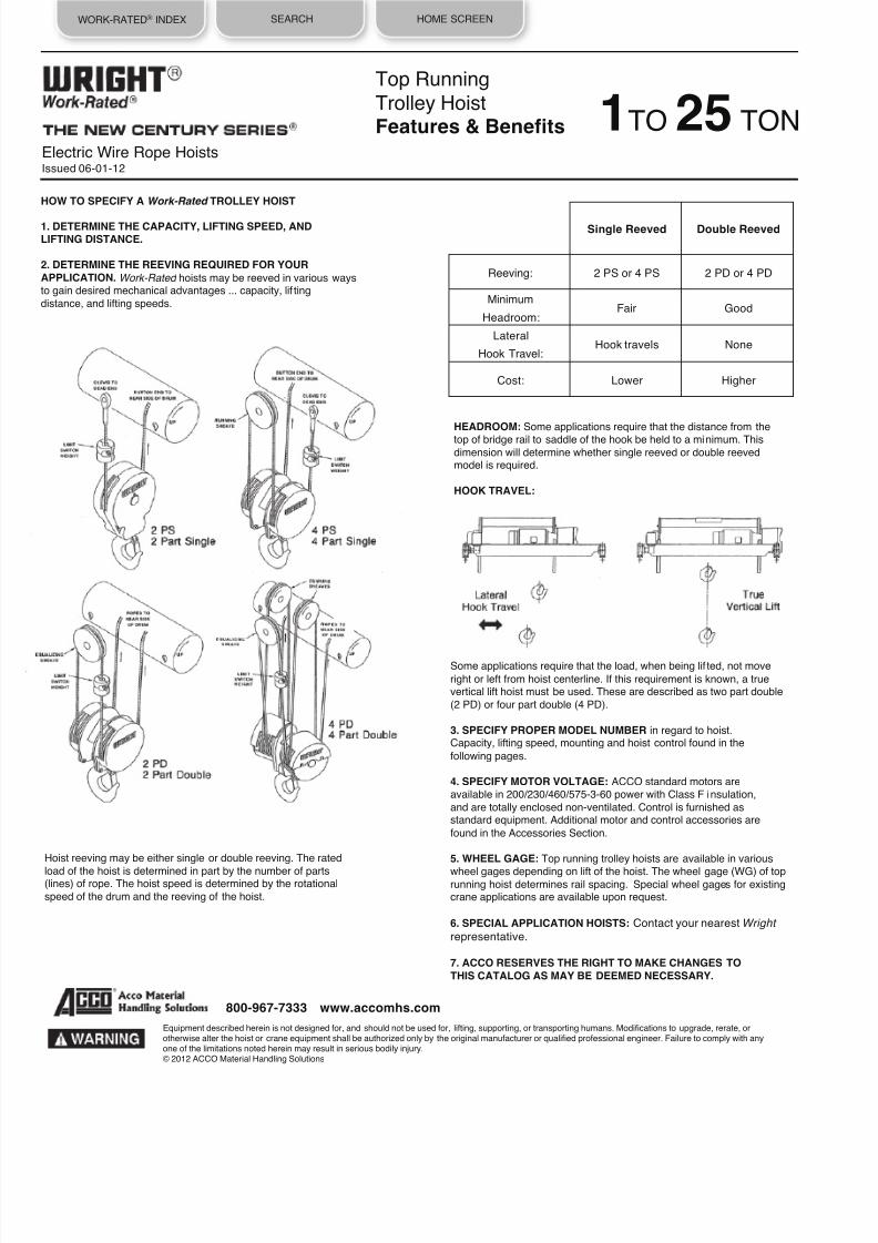
8/21/2019 2013 Wright Specifications Catalog
http://slidepdf.com/reader/full/2013-wright-specifications-catalog 99/189
WORK-RATED® INDEX SEARCH HOME SCREEN
Electric Wire Rope HoistsIssued 06-01-12
HOW TO SPECIFY A Work-Rated TROLLEY HOIST
1. DETERMINE THE CAPACITY, LIFTING SPEED, ANDLIFTING DISTANCE.
2. DETERMINE THE REEVING REQUIRED FOR YOUR
APPLICATION. Work-Rated hoists may be reeved in various waysto gain desired mechanical advantages ... capacity, lif ting
distance, and lifting speeds.
HEADROOM: Some applications require that the distance from the
top of bridge rail to saddle of the hook be held to a minimum. Thisdimension will determine whether single reeved or double reevedmodel is required.
HOOK TRAVEL:
Top Running
Trolley HoistFeatures & Benefits 1TO 25 TON
Hoist reeving may be either single or double reeving. The rated
load of the hoist is determined in part by the number of parts(lines) of rope. The hoist speed is determined by the rotational
speed of the drum and the reeving of the hoist.
Single Reeved
Double Reeved
Reeving:
2 PS or 4 PS
2 PD or 4 PD
Minimum
Fair
Good
Headroom:
Lateral Hook travels None
Hook Travel:
Cost:
Lower
Higher
Some applications require that the load, when being lif ted, not move
right or left from hoist centerline. If this requirement is known, a truevertical lift hoist must be used. These are described as two part double
(2 PD) or four part double (4 PD).
3. SPECIFY PROPER MODEL NUMBER in regard to hoist.Capacity, lifting speed, mounting and hoist control found in the
following pages.
4. SPECIFY MOTOR VOLTAGE: ACCO standard motors areavailable in 200/230/460/575-3-60 power with Class F insulation,
and are totally enclosed non-ventilated. Control is furnished asstandard equipment. Additional motor and control accessories are
found in the Accessories Section.
5. WHEEL GAGE: Top running trolley hoists are available in various
wheel gages depending on lift of the hoist. The wheel gage (WG) of toprunning hoist determines rail spacing. Special wheel gages for existingcrane applications are available upon request.
6. SPECIAL APPLICATION HOISTS: Contact your nearest Wright
representative.
7. ACCO RESERVES THE RIGHT TO MAKE CHANGES TO
THIS CATALOG AS MAY BE DEEMED NECESSARY.
Equipment described herein is not designed for, and should not be used for, lifting, supporting, or transporting humans. Modifications to upgrade, rerate, orotherwise alter the hoist or crane equipment shall be authorized only by the original manufacturer or qualified professional engineer. Failure to comply with anyone of the limitations noted herein may result in serious bodily injury.© 2012 ACCO Material Handling Solutions
800-967-7333 www.accomhs.com

8/21/2019 2013 Wright Specifications Catalog
http://slidepdf.com/reader/full/2013-wright-specifications-catalog 100/189
VIEW PRICING
FOR THIS PRODUCTWORK-RATED® INDEX SEARCH HOME SCREEN
Electric Wire Rope HoistsIssued 06-03-13
Top Running Trolley Hoist
Series 322 Part Single Reeved
3/8 Diameter Rope
WHEEL LOADING
Lift (Ft)
Weight Pounds Per Wheel (Max)
W1 W2
17 1198 826 848
33 1244 871 88851 1297 925 934
83 1389 969 999
MODEL NUMBER
Lift
(Ft) Lift
Speed
(FPM)
HP B C J K
Trolley Drive
Hook
Travel
Wheel
Gage
(WG)
Drum
Single
Two
Speed Speed
F (a) F (a) HT
C2W01S017-15T2S0 17 15 3 16-1/4 16-15/16 22-3/16 23-1/16 16-5/8 17-5/8 2-1/4 60 1
C2W01S033-15T2S0 33 15 3 21-7/8 18-13/16 16-9/16 21-3/16 16-5/8 17-5/8 4-1/8 60 3
C2W01S051-15T2S0 51 15
3
28-7/16 21 10 19 16-5/8 17-5/8 6-5/16 60
4
C2W01S083-15T2S0 83 15 3 39-11/16 24-3/4 7-3/4 24-1/4 16-5/8 17-5/8 10-1/16 78 6
C2W01S017-22T2S0 17 22
3
16-1/4 16-15/16 22-3/16 23-1/16 16-5/8 17-5/8 2-1/4 60
1
C2W01S033-22T2S0 33 22
3
21-7/8 18-13/16 16-9/16 21-3/16 16-5/8 17-5/8 4-1/8 60
3
C2W01S051-22T2S0 51 22 3 28-7/16 21 10 19 16-5/8 17-5/8 6-5/16 60 4
C2W01S083-22T2S0 83 22 3 39-11/16 24-3/4 7-3/4 24-1/4 16-5/8 17-5/8 10-1/16 78 6
C2W01S017-30T2S0 17 30 3 16-1/4 16-15/16 22-3/16 23-1/16 16-5/8 17-5/8 2-1/4 60 1
C2W01S033-30T2S0 33 30
3
21-7/8 18-13/16 16-9/16 21-3/16 16-5/8 17-5/8 4-1/8 60
3
C2W01S051-30T2S0 51 30
3
28-7/16 21 10 19 16-5/8 17-5/8 6-5/16 60
4
C2W01S083-30T2S0 83 30 3 39-11/16 24-3/4 7-3/4 24-1/4 16-5/8 17-5/8 10-1/16 78 6
TON1For Pricing See Page 1t
t1
Equipment described herein is not designed for, and should not be used for, lifting, supporting, or transporting humans. Modifications to upgrade, rerate, orotherwise alter the hoist or crane equipment shall be authorized only by the original manufacturer or qualified professional engineer. Failure to comply with any
one of the limitations noted herein may result in serious bodily injury.© 2013 ACCO Material Handling Solutions
800-967-7333 www.accomhs.com
All dimensions shown in inches unless otherwise specified.(a) Trolley brake is available as optional equipment. Add 5-1/8" to dimension F.(b) Four rubber bumpers are available as optional equipment.Rail gage (beam spacing of the crane) must match wheel gage of the top running trolley hoist based on lift and drum length.All two speed motors are 1800/600 RPM.
TROLLEY DATA: Speed 32 FPM 65 FPM 125 FPMHP 1/2 1/2 1/2 (2 OF EACH REQUIRED FOR 78 WHEEL GAGE)
Wheel Dia. 6
Max. Rail Size - 30 #/Yd.

8/21/2019 2013 Wright Specifications Catalog
http://slidepdf.com/reader/full/2013-wright-specifications-catalog 101/189
VIEW PRICING
FOR THIS PRODUCTWORK-RATED® INDEX SEARCH HOME SCREEN
Top Running Trolley Hoist
Series 332 Part Single Reeved
1/2 Diameter Rope
MODEL NUMBER
Lift (Ft)
Lift
Speed
(FPM) HP
B
C
J
K
Trolley Drive
Hook
Travel
Wheel
Gage
(WG) Drum
Single
Two Speed Speed
F (a) F (a) HT
C3W01S017-44T2S0 17 44 7-1/2 19-1/4 17-1/2 21 22-5/16 16-5/8 17-5/8 2-3/8 60 1
C3W01S041-44T2S0 41 44 7-1/2 24-9/16 20-5/16 13-13/16 19-1/2 16-5/8 17-5/8 4-15/16 60 2
C3W01S064-44T2S0 64 44 7-1/2 32-13/16 23-1/16 5-9/16 16-3/4 16-5/8 17-5/8 7-11/16 60 3
C3W01S091-44T2S0 91 44 7-1/2 42-9/16 26-5/16 4-13/16 22-1/2 16-5/8 17-5/8 10-15/16 78 4
C3W01S133-44T2S0 133 44 7-1/2 57-9/16 31-5/16 10-13/16 38-1/2 16-5/8 17-5/8 15-15/16 120 5
All dimensions shown in inches unless otherwise specified.(a) Trolley brake is available as optional equipment. Add 5-1/8" to dimension F.(b) Four rubber bumpers are available as optional equipment.Rail gage (beam spacing of the crane) must match wheel gage of the top running trolley hoist based on lift and drum length.All two speed motors are 1800/600 RPM.
TROLLEY DATA: Speed 32 FPM 65 FPM 125 FPM
HP 1/2 1/2 1/2 (2 OF EACH REQUIRED FOR 78 & 120 WHEEL GAGES)
Wheel Dia. 6
Max. Rail Size - 30 #/Yd.
WHEEL LOADING
Lift (Ft)
Weight Pounds Per Wheel (Max)
W1 W2
17 1628 926 964
41 1719 994 1029
64 1820 1080 1084
91 1974 1150 1116
133 2362 1253 1193
t2
Equipment described herein is not designed for, and should not be used for, lifting, supporting, or transporting humans. Modifications to upgrade, rerate, or
otherwise alter the hoist or crane equipment shall be authorized only by the original manufacturer or qualified professional engineer. Failure to comply with anyone of the limitations noted herein may result in serious bodily injury.© 2012 ACCO Material Handling Solutions
800-967-7333 www.accomhs.com
TON 1For Pricing See Page 1t
Electric Wire Rope HoistsIssued 06-01-12

8/21/2019 2013 Wright Specifications Catalog
http://slidepdf.com/reader/full/2013-wright-specifications-catalog 102/189
VIEW PRICING
FOR THIS PRODUCTWORK-RATED® INDEX SEARCH HOME SCREEN
Electric Wire Rope HoistsIssued 06-03-13
Top Running Trolley Hoist
Series 322 Part Single Reeved
3/8 Diameter Rope
All dimensions shown in inches unless otherwise specified.(a) Trolley brake is available as optional equipment. Add 5-1/8" to dimension F.(b) Four rubber bumpers are available as optional equipment.Rail gage (beam spacing of the crane) must match wheel gage of the top running trolley hoist based on lift and drum length.All two speed motors are 1800/600 RPM.
TROLLEY DATA: Speed 32 FPM 65 FPM 125 FPMHP 1/2 1/2 1/2 (2 OF EACH REQUIRED FOR 78 WHEEL GAGE)
t3
Equipment described herein is not designed for, and should not be used for, lifting, supporting, or transporting humans. Modifications to upgrade, rerate, orotherwise alter the hoist or crane equipment shall be authorized only by the original manufacturer or qualified professional engineer. Failure to comply with anyone of the limitations noted herein may result in serious bodily injury.© 2013 ACCO Material Handling Solutions
800-967-7333 www.accomhs.com
Wheel Dia. 6Max. Rail Size - 30 #/Yd.
WHEEL LOADING
Lift (Ft)
Weight Pounds Per Wheel (Max)
W1 W2
17 1198 1415 1442
33 1244 1425 1672
51 1297 1690 1805
83 1389 1617 1850
MODEL NUMBER
Lift
(Ft)
Lift
Speed
(FPM)
HP B C J K
Trolley Drive
Hook
Travel Wheel
Gage
(WG)
Drum
Single Two
Speed Speed
F (a) F (a) HT
C2W02S017-15T2S0 17 15
3
16-1/4 16-15/16 22-3/16 23-1/16 16-5/8 17-5/8 2-1/4 60
1
C2W02S033-15T2S0 33 15
3
21-7/8 18-13/16 16-9/16 21-3/16 16-5/8 17-5/8 4-1/8 60
3
C2W02S051-15T2S0 51 15 3 28-7/16 21 10 19 16-5/8 17-5/8 6-5/16 60 4
C2W02S083-15T2S0 83 15 3 39-11/16 24-3/4 7-3/4 24-1/4 16-5/8 17-5/8 10-1/16 78 6
C2W02S017-22T2S0 17 22 3 16-1/4 16-15/16 22-3/16 23-1/16 16-5/8 17-5/8 2-1/4 60 1
C2W02S033-22T2S0 33 22
3
21-7/8 18-13/16 16-9/16 21-3/16 16-5/8 17-5/8 4-1/8 60
3
C2W02S051-22T2S0 51 22
3
28-7/16 21 10 19 16-5/8 17-5/8 6-5/16 60
4
C2W02S083-22T2S0 83 22 3 39-11/16 24-3/4 7-3/4 24-1/4 16-5/8 17-5/8 10-1/16 78 6
C2W02S017-30T2S0 17 30
5
16-1/4 16-15/16 22-3/16 23-1/16 16-5/8 17-5/8 2-1/4 60
1
C2W02S033-30T2S0 33 30
5
21-7/8 18-13/16 16-9/16 21-3/16 16-5/8 17-5/8 4-1/8 60
3
C2W02S051-30T2S0 51 30 5 28-7/16 21 10 19 16-5/8 17-5/8 6-5/16 60 4
C2W02S083-30T2S0
83
30
5
39-11/16 24-3/4 7-3/4 24-1/4 16-5/8 17-5/8 10-1/16 78
6
TON2For Pricing See Page 2t

8/21/2019 2013 Wright Specifications Catalog
http://slidepdf.com/reader/full/2013-wright-specifications-catalog 103/189
VIEW PRICING
FOR THIS PRODUCTWORK-RATED® INDEX SEARCH HOME SCREEN
Electric Wire Rope HoistsIssued 06-01-12
Top Running Trolley Hoist
Series 332 Part Single Reeved
1/2 Diameter Rope
t4
MODEL NUMBER
Lift
(Ft)
Lift Speed
(FPM) HP B C J K
Trolley Drive
Hook Travel
Wheel Gage
(WG) Drum
Single
Two
Speed Speed
F (a) F (a) HT
C3W02S017-44T2S0 17 44 7-1/2 19-1/4 17-1/2 21 22-5/16 16-5/8 17-5/8 2-3/8 60 1
C3W02S041-44T2S0 41 44 7-1/2 24-9/16 20-5/16 13-13/16 19-1/2 16-5/8 17-5/8 4-15/16 60 2
C3W02S064-44T2S0 64 44 7-1/2 32-13/16 23-1/16 5-9/16 16-3/4 16-5/8 17-5/8 7-11/16 60 3
C3W02S091-44T2S0 91 44 7-1/2 42-9/16 26-5/16 4-13/16 22-1/2 16-5/8 17-5/8 10-15/16 78 4
C3W02S133-44T2S0 133 44 7-1/2 57-9/16 31-5/16 10-13/16 38-1/2 16-5/8 17-5/8 15-15/16 120 5
All dimensions shown in inches unless otherwise specified.(a) Trolley brake is available as optional equipment. Add 5-1/8" to dimension F.(b) Four rubber bumpers are available as optional equipment.Rail gage (beam spacing of the crane) must match wheel gage of the top running trolley hoist based on lift and drum length.All two speed motors are 1800/600 RPM.
TROLLEY DATA: Speed 32 FPM 65 FPM 125 FPM
HP 1/2 1/2 1/2 (2 OF EACH REQUIRED FOR 78 & 120 WHEEL GAGES)
Wheel Dia. 6
Max. Rail Size - 30 #/Yd.
WHEEL LOADING
Lift (Ft)
Weight Pounds Per Wheel (Max)
W1 W2
17 1628 1465 1503
41 1719 1575 1610
64 1820 1707 1712
91 1974 1789 1755
133 2362 1885 1825
Equipment described herein is not designed for, and should not be used for, lifting, supporting, or transporting humans. Modifications to upgrade, rerate, orotherwise alter the hoist or crane equipment shall be authorized only by the original manufacturer or qualified professional engineer. Failure to comply with anyone of the limitations noted herein may result in serious bodily injury.© 2012 ACCO Material Handling Solutions
800-967-7333 www.accomhs.com
TON 2For Pricing See Page 2t

8/21/2019 2013 Wright Specifications Catalog
http://slidepdf.com/reader/full/2013-wright-specifications-catalog 104/189
VIEW PRICING
FOR THIS PRODUCTWORK-RATED® INDEX SEARCH HOME SCREEN
Electric Wire Rope HoistsIssued 06-03-13
Top Running Trolley Hoist
Series 322 Part Single Reeved
3/8 Diameter Rope
All dimensions shown in inches unless otherwise specified.(a) Trolley brake is available as optional equipment. Add 5-1/8" to dimension F.
(b) Four rubber bumpers are available as optional equipment.Rail gage (beam spacing of the crane) must match wheel gage of the top running trolley hoist based on lift and drum length.All two speed motors are 1800/600 RPM.
TROLLEY DATA: Speed 32 FPM 65 FPM 125 FPMHP 1/2 1/2 1/2 (2 OF EACH REQUIRED FOR 78 WHEEL GAGE)
t5
Equipment described herein is not designed for, and should not be used for, lifting, supporting, or transporting humans. Modifications to upgrade, rerate, orotherwise alter the hoist or crane equipment shall be authorized only by the original manufacturer or qualified professional engineer. Failure to comply with anyone of the limitations noted herein may result in serious bodily injury.© 2013 ACCO Material Handling Solutions
800-967-7333 www.accomhs.com
Wheel Dia. 6Max. Rail Size - 30 #/Yd.
WHEEL LOADING
Lift (Ft)
Weight Pounds Per Wheel (Max)
W1 W2
17 1198 1915 1942
33 1244 1925 2172
51 1297 2190 2305
83 1389 2117 2350
MODEL NUMBER
Lift
(Ft) Lift
Speed
(FPM) HP B C J K
Trolley Drive
Hook
Travel Wheel
Gage
(WG) DrumSingle
Two
Speed Speed
F (a) F (a) HT
C2W03S017-15T2S0 17 15 3 16-1/4 16-15/16 22-3/16 23-1/16 16-5/8 17-5/8 2-1/4 60 1
C2W03S033-15T2S0 33 15 3 21-7/8 18-13/16 16-9/16 21-3/16 16-5/8 17-5/8 4-1/8 60 3
C2W03S051-15T2S0 51 15
3
28-7/16 21 10 19 16-5/8 17-5/8 6-5/16 60
4
C2W03S083-15T2S0 83 15 3 39-11/16 24-3/4 7-3/4 24-1/4 16-5/8 17-5/8 10-1/16 78 6
C2W03S017-22T2S0 17 22
5
16-1/4 16-15/16 22-3/16 23-1/16 16-5/8 17-5/8 2-1/4 60
1
C2W03S033-22T2S0 33 22
5
21-7/8 18-13/16 16-9/16 21-3/16 16-5/8 17-5/8 4-1/8 60
3
C2W03S051-22T2S0 51 22 5 28-7/16 21 10 19 16-5/8 17-5/8 6-5/16 60 4
C2W03S083-22T2S0 83 22 5 39-11/16 24-3/4 7-3/4 24-1/4 16-5/8 17-5/8 10-1/16 78 6
TON3For Pricing See Page 3t

8/21/2019 2013 Wright Specifications Catalog
http://slidepdf.com/reader/full/2013-wright-specifications-catalog 105/189
VIEW PRICING
FOR THIS PRODUCTWORK-RATED® INDEX SEARCH HOME SCREEN
Electric Wire Rope HoistsIssued 06-01-12
Top Running Trolley Hoist
Series 332 Part Single Reeved
1/2 Diameter Rope
t6
MODEL NUMBER
Lift (Ft)
Lift Speed
(FPM)
HP
B
C
J
K
Trolley Drive
Hook
Travel
Wheel Gage
(WG)
Drum
Single
Two
Speed Speed
F (a) F (a) HT
C3W03S017-30T2S0 17 30 7-1/2 19-1/4 17-1/2 21 22-5/16 16-5/8 17-5/8 2-3/8 60 1
C3W03S041-30T2S0 41 30 7-1/2 24-9/16 20-5/16 13-13/16 19-1/2 16-5/8 17-5/8 4-15/16 60 2
C3W03S064-30T2S0 64 30 7-1/2 32-13/16 23-1/16 5-9/16 16-3/4 16-5/8 17-5/8 7-11/16 60 3
C3W03S091-30T2S0 91 30 7-1/2 42-9/16 26-5/16 4-13/16 22-1/2 16-5/8 17-5/8 10-15/16 78 4
C3W03S133-30T2S0 133 30 7-1/2 57-9/16 31-5/16 10-13/16 38-1/2 16-5/8 17-5/8 15-15/16 120 5
C3W03S017-44T2S0 17 44 10 19-1/4 17-1/2 21 22-5/16 16-5/8 17-5/8 2-3/8 60 1
C3W03S041-44T2S0 41 44 10 24-9/16 20-5/16 13-13/16 19-1/2 16-5/8 17-5/8 4-15/16 60 2
C3W03S064-44T2S0 64 44 10 32-13/16 23-1/16 5-9/16 16-3/4 16-5/8 17-5/8 7-11/16 60 3
C3W03S091-44T2S0 91 44 10 42-9/16 26-5/16 4-13/16 22-1/2 16-5/8 17-5/8 10-15/16 78 4
C3W03S133-44T2S0 133 44 10 57-9/16 31-5/16 10-13/16 38-1/2 16-5/8 17-5/8 15-15/16 120 5
All dimensions shown in inches unless otherwise specified.
(a) Trolley brake is available as optional equipment. Add 5-1/8" to dimension F.(b) Four rubber bumpers are available as optional equipment.Rail gage (beam spacing of the crane) must match wheel gage of the top running trolley hoist based on lift and drum length.All two speed motors are 1800/600 RPM.
TROLLEY DATA: Speed 32 FPM 65 FPM 125 FPMHP 1/2 1/2 1/2 (2 OF EACH REQUIRED FOR 78 & 120 WHEEL GAGES)
Wheel Dia. 6
Max. Rail Size - 30 #/Yd.
WHEEL LOADING
Lift (Ft)
Weight Pounds Per Wheel (Max)
W1 W2
17 1628 2004 2041
41 1719 2156 2193
64 1820 2334 2339
91 1974 2429 2395
133 2362 2517 2457
Equipment described herein is not designed for, and should not be used for, lifting, supporting, or transporting humans. Modifications to upgrade, rerate, orotherwise alter the hoist or crane equipment shall be authorized only by the original manufacturer or qualified professional engineer. Failure to comply with anyone of the limitations noted herein may result in serious bodily injury.© 2012 ACCO Material Handling Solutions
800-967-7333 www.accomhs.com
TON 3For Pricing See Page 3t

8/21/2019 2013 Wright Specifications Catalog
http://slidepdf.com/reader/full/2013-wright-specifications-catalog 106/189
WORK-RATED® INDEX SEARCH HOME SCREEN
Electric Wire Rope HoistsIssued 06-01-12
Top Running Trolley Hoist
Series 332 Part Single Reeved
1/2 Diameter Rope
MODEL NUMBER
Lift
(Ft)
Lift Speed
(FPM)
HP B C J K
Trolley Drive
Hook Travel
Wheel Gage
(WG)
Drum
Single
Two
Speed Speed
F (a) F (a) HT
C3W05S017-22T2S0 17 22 7-1/2 19-1/4 17-1/2 21 22-5/16 16-5/8 17-5/8 2-3/8 60 1
C3W05S041-22T2S0 41 22 7-1/2 24-9/16 20-5/16 13-13/16 19-1/2 16-5/8 17-5/8 4-15/16 60 2
C3W05S064-22T2S0 64 22 7-1/2 32-13/16 23-1/16 5-9/16 16-3/4 16-5/8 17-5/8 7-11/16 60 3
C3W05S091-22T2S0 91 22 7-1/2 42-9/16 26-5/16 4-13/16 22-1/2 16-5/8 17-5/8 10-15/16 78 4
C3W05S133-22T2S0 133 22 7-1/2 57-9/16 31-5/16 10-13/16 38-1/2 16-5/8 17-5/8 15-15/16 120 5
C3W05S017-30T2S0 17 30 10 19-1/4 17-1/2 21 22-5/16 16-5/8 17-5/8 2-3/8 60 1
C3W05S041-30T2S0 41 30 10 24-9/16 20-5/16 13-13/16 19-1/2 16-5/8 17-5/8 4-15/16 60 2
C3W05S064-30T2S0 64 30 10 32-13/16 23-1/16 5-9/16 16-3/4 16-5/8 17-5/8 7-11/16 60 3
C3W05S091-30T2S0 91 30 10 42-9/16 26-5/16 4-13/16 22-1/2 16-5/8 17-5/8 10-15/16 78 4
C3W05S133-30T2S0 133 30 10 57-9/16 31-5/16 10-13/16 38-1/2 16-5/8 17-5/8 15-15/16 120 5
All dimensions shown in inches unless otherwise specified.
(a) Trolley brake is available as optional equipment. Add 5-1/8" to dimension F.(b) Four rubber bumpers are available as optional equipment.Rail gage (beam spacing of the crane) must match wheel gage of the top running trolley hoist based on lift and drum length.All two speed motors are 1800/600 RPM.
TROLLEY DATA: Speed 32 FPM 65 FPM 125 FPMHP 1/2
1/2
1/2 (2 OF EACH REQUIRED FOR 78 & 120 WHEEL GAGES)
Wheel Dia. 6Max. Rail Size - 30 #/Yd.
t7
WHEEL LOADING
Lift (Ft)
Weight Pounds Per Wheel (Max)
W1 W2
17 1628 3081 3118
41 1719 3329 3343
64 1820 3588 3593
91 1974 3708 3674
133 2362 3782 3722
Equipment described herein is not designed for, and should not be used for, lifting, supporting, or transporting humans. Modifications to upgrade, rerate, orotherwise alter the hoist or crane equipment shall be authorized only by the original manufacturer or qualified professional engineer. Failure to comply with anyone of the limitations noted herein may result in serious bodily injury.© 2012 ACCO Material Handling Solutions
800-967-7333 www.accomhs.com
TON5For Pricing See Page 4t

8/21/2019 2013 Wright Specifications Catalog
http://slidepdf.com/reader/full/2013-wright-specifications-catalog 107/189
WORK-RATED® INDEX SEARCH HOME SCREEN
Electric Wire Rope HoistsIssued 06-01-12
Top Running Trolley Hoist
Series 334 Part Single Reeved
1/2 Diameter Rope
MODEL NUMBER
Lift
(Ft) Lift
Speed
(FPM) HP B C J K
Trolley Drive
Hook Travel Wheel
Gage
(WG) Drum
Single
Two
Speed Speed
F (a) F (a) HT
C3W07S024-15T4S0 24 15 7-1/2 34-15/16 20-15/16 3-5/8 19-1/8 17-9/16 18-9/16 2-3/4 60 3
C3W07S038-15T4S0 38 15 7-1/2 46-7/16 22-7/16 9-7/8 35-3/8 17-9/16 18-9/16 4-1/4 96 4
C3W07S059-15T4S0 59 15 7-1/2 63-15/16 24-15/16 4-3/8 44-7/8 17-9/16 18-9/16 6-3/4 120 5
C3W07S024-22T4S0 24 22 10 34-15/16 20-15/16 3-5/8 19-1/8 17-9/16 18-9/16 2-3/4 60 3
C3W07S038-22T4S0 38 22 10 46-7/16 22-7/16 9-7/8 35-3/8 17-9/16 18-9/16 4-1/4 96 4
C3W07S059-22T4S0 59 22 10 63-15/16 24-15/16 4-3/8 44-7/8 17-9/16 18-9/16 6-3/4 120 5
All dimensions shown in inches unless otherwise specified.(a) Trolley brake is available as optional equipment. Add 5-1/8" to dimension F.(b) Four rubber bumpers are available as optional equipment.Rail gage (beam spacing of the crane) must match wheel gage of the top running trolley hoist based on lift and drum length.All two speed motors are 1800/600 RPM.
TROLLEY DATA: Speed 32 FPM 65 FPM 125 FPMHP 1/2 1/2 1/2 (2 OF EACH REQUIRED FOR 96 & 120 WHEEL GAGES)
Wheel Dia. 8Max. Rail Size - 30 #/Yd.
t8
WHEEL LOADING
Lift (Ft)
Weight Pounds Per Wheel (Max)
W1 W2
24 2319 4605 4742
38 2693 4731 4780
59 3053 4959 4921
Equipment described herein is not designed for, and should not be used for, lifting, supporting, or transporting humans. Modifications to upgrade, rerate, orotherwise alter the hoist or crane equipment shall be authorized only by the original manufacturer or qualified professional engineer. Failure to comply with anyone of the limitations noted herein may result in serious bodily injury.© 2012 ACCO Material Handling Solutions
800-967-7333 www.accomhs.com
For Pricing See Page 5t
TON 71
2

8/21/2019 2013 Wright Specifications Catalog
http://slidepdf.com/reader/full/2013-wright-specifications-catalog 108/189
WORK-RATED® INDEX SEARCH HOME SCREEN
Electric Wire Rope HoistsIssued 06-01-12
Top Running Trolley Hoist
Series 334 Part Single Reeved
1/2 Diameter Rope
MODEL NUMBER
Lift
(Ft) Lift
Speed
(FPM) HP B C J K
Trolley Drive
Hook
Travel Wheel Gage
(WG) Drum
Single
Two
Speed Speed
F (a) F (a) HT
C3W10S024-15T4S0 24 15 10 34-15/16 20-15/16 3-5/8 19-1/8 17-9/16 18-9/16 2-3/4 60 3
C3W10S038-15T4S0 38 15 10 46-7/16 22-7/16 9-7/8 35-3/8 17-9/16 18-9/16 4-1/4 96 4
C3W10S059-15T4S0 59 15 10 63-15/16 24-15/16 4-3/8 44-7/8 17-9/16 18-9/16 6-3/4 120 5
All dimensions shown in inches unless otherwise specified.(a) Trolley brake is available as optional equipment. Add 5-1/8" to dimension F.(b) Four rubber bumpers are available as optional equipment.Rail gage (beam spacing of the crane) must match wheel gage of the top running trolley hoist based on lift and drum length.All two speed motors are 1800/600 RPM.
TROLLEY DATA: Speed 32 FPM 65 FPM 125 FPM
HP 1/2
1/2
1 (2 OF EACH REQUIRED FOR 96 & 120 WHEEL GAGES)
Wheel Dia. 8Max. Rail Size - 30 #/Yd.
t9
WHEEL LOADING
Lift (Ft)
Weight Pounds Per Wheel (Max)
W1 W2
24 2319 5970 6170
38 2693 6092 6140
59 3053 6350 6302
Equipment described herein is not designed for, and should not be used for, lifting, supporting, or transporting humans. Modifications to upgrade, rerate, orotherwise alter the hoist or crane equipment shall be authorized only by the original manufacturer or qualified professional engineer. Failure to comply with anyone of the limitations noted herein may result in serious bodily injury.© 2012 ACCO Material Handling Solutions
800-967-7333 www.accomhs.com
TON10For Pricing See Page 6t

8/21/2019 2013 Wright Specifications Catalog
http://slidepdf.com/reader/full/2013-wright-specifications-catalog 109/189
WORK-RATED® INDEX SEARCH HOME SCREEN
Electric Wire Rope HoistsIssued 06-01-12
Top Running Trolley Hoist
Series 344 Part Single Reeved
5/8 Diameter Rope
MODEL NUMBER
Lift
(Ft) Lift
Speed
(FPM) HP B C J K
Trolley Drive
Hook
Travel Wheel
Gage
(WG) Drum
Single
Two
Speed Speed
F (a) F (a) HT
C4W10S025-22T4S0 25 22 15 37-3/4 26-1/8 9-1/4 26-3/4 15-7/8 18-3/8 2-7/8 78 3
C4W10S038-22T4S0 38 22 15 48-1/4 27-5/8 7-3/4 34-1/4 15-7/8 18-3/8 4-3/8 96 4
All dimensions shown in inches unless otherwise specified.(a) Trolley brake is available as optional equipment. Add 5-1/8" to dimension F.(b) Four rubber bumpers are available as optional equipment.Rail gage (beam spacing of the crane) must match wheel gage of the top running trolley hoist based on lift and drum length.All two speed motors are 1800/600 RPM.
TROLLEY DATA: Speed 32 FPM 65 FPM 125 FPMHP 1/2
1/2
1 (2 OF EACH REQUIRED FOR ALL WHEEL GAGES)
Wheel Dia. 8
Max. Rail Size - 30 #/Yd.
t10
WHEEL LOADING
Lift
(Ft) Weight
Pounds Per Wheel (Max)
W1 W2
25 3464 6248 6221
38 3696 6448 6311
Equipment described herein is not designed for, and should not be used for, lifting, supporting, or transporting humans. Modifications to upgrade, rerate, orotherwise alter the hoist or crane equipment shall be authorized only by the original manufacturer or qualified professional engineer. Failure to comply with anyone of the limitations noted herein may result in serious bodily injury.© 2012 ACCO Material Handling Solutions
800-967-7333 www.accomhs.com
TON 10For Pricing See Page 6t

8/21/2019 2013 Wright Specifications Catalog
http://slidepdf.com/reader/full/2013-wright-specifications-catalog 110/189
WORK-RATED® INDEX SEARCH HOME SCREEN
Electric Wire Rope HoistsIssued 06-01-12
Top Running Trolley Hoist
Series 344 Part Single Reeved
5/8 Diameter Rope
WHEEL LOADING
Lift
(Ft) Weight
Pounds Per Wheel (Max)
W1 W2
25 3464 8932 8905
38 3696 9176 9039
Wheel Dia. 8
Max. Rail Size - 30 #/Yd.
MODEL NUMBER
Lift (Ft)
Lift
Speed
(FPM) HP
B
C
J
K
Trolley Drive
Hook
Travel
Wheel
Gage
(WG) DrumSingle
Two
Speed Speed
F (a) F (a) HT
C4W15S025-15T4S0 25 15 15 37-3/4 26-1/8 9-1/4 26-3/4 15-7/8 18-3/8 2-7/8 78 3
C4W15S038-15T4S0 38 15 15 48-1/4 27-5/8 7-3/4 34-1/4 15-7/8 18-3/8 4-3/8 96 4
All dimensions shown in inches unless otherwise specified.(a) Trolley brake is available as optional equipment. Add 5-1/8" to dimension F.(b) Four rubber bumpers are available as optional equipment.Rail gage (beam spacing of the crane) must match wheel gage of the top running trolley hoist based on lift and drum length.All two speed motors are 1800/600 RPM.
TROLLEY DATA: Speed 32 FPM 65 FPM 125 FPMHP 1/2 1/2 1 (2 OF EACH REQUIRED FOR ALL WHEEL GAGE
t11
Equipment described herein is not designed for, and should not be used for, lifting, supporting, or transporting humans. Modifications to upgrade, rerate, orotherwise alter the hoist or crane equipment shall be authorized only by the original manufacturer or qualified professional engineer. Failure to comply with anyone of the limitations noted herein may result in serious bodily injury.© 2012 ACCO Material Handling Solutions
800-967-7333 www.accomhs.com
TON15For Pricing See Page 7t

8/21/2019 2013 Wright Specifications Catalog
http://slidepdf.com/reader/full/2013-wright-specifications-catalog 111/189
WORK-RATED® INDEX SEARCH HOME SCREEN
Electric Wire Rope HoistsIssued 06-01-12
Top Running Trolley Hoist
Series 354 Part Single Reeved
3/4 Diameter Rope
MODEL NUMBER
Lift
(Ft) Lift
Speed
(FPM) HP B C J K
Trolley Drive
Hook
Travel
Wheel
Gage
(WG) Drum
Single
Two
Speed Speed
F (a) F (a) HT
C5W15S021*-22T4S0 21 22 20 36-7/8 28-5/8 10-1/2 25-1/4 15-7/8 18-3/8 2-5/8 78 3
C5W15S034*-22T4S0 34 22
20
47-3/8
30-1/8
9
32-3/4
15-7/8
18-3/8
4-1/8
96
4
All dimensions shown in inches unless otherwise specified.(a) Trolley brake is available as optional equipment. Add 5-1/8" to dimension F.(b) Four rubber bumpers are available as optional equipment.Rail gage (beam spacing of the crane) must match wheel gage of the top running trolley hoist based on lift and drum length.All two speed motors are 1800/600 RPM.
TROLLEY DATA: Speed 32 FPM 65 FPM 125 FPMHP 1/2 1/2 1 (2 OF EACH REQUIRED FOR ALL WHEEL GAGES)
WHEEL LOADING
Lift (Ft)
Weight Pounds Per Wheel (Max)
W1 W2
21
4535
9185
9092
34 4900 9487 9253
Wheel Dia. 8Max. Rail Size - 30 #/Yd.
t12
Equipment described herein is not designed for, and should not be used for, lifting, supporting, or transporting humans. Modifications to upgrade, rerate, orotherwise alter the hoist or crane equipment shall be authorized only by the original manufacturer or qualified professional engineer. Failure to comply with anyone of the limitations noted herein may result in serious bodily injury.© 2012 ACCO Material Handling Solutions
800-967-7333 www.accomhs.com
TON 15For Pricing See Page 7t

8/21/2019 2013 Wright Specifications Catalog
http://slidepdf.com/reader/full/2013-wright-specifications-catalog 112/189
WORK-RATED® INDEX SEARCH HOME SCREEN
Electric Wire Rope HoistsIssued 06-01-12
Top Running Trolley Hoist
Series 354 Part Single Reeved
3/4 Diameter Rope
WHEEL LOADING
Lift (Ft)
Weight Pounds Per Wheel (Max)
W1 W2
21 4535 11854 11760
34 4900 12202 11967
Wheel Dia. 8
Max. Rail Size - 30 #/Yd.
MODEL NUMBER
Lift (Ft)
Lift
Speed
(FPM) HP
B
C
J
K
Trolley Drive
Hook
Travel
Wheel
Gage
(WG) DrumSingle
Two
Speed Speed
F (a) F (a) HT
C5W20S021-15T4S0 21 15 20 36-7/8 28-5/8 10-1/2 25-1/4 15-7/8 18-3/8 2-5/8 78 3
C5W20S034-15T4S0 34 15 20 47-3/8 30-1/8 9 32-3/4 15-7/8 18-3/8 4-1/8 96 4
All dimensions shown in inches unless otherwise specified.(a) Trolley brake is available as optional equipment. Add 5-1/8" to dimension F.(b) Four rubber bumpers are available as optional equipment.Rail gage (beam spacing of the crane) must match wheel gage of the top running trolley hoist based on lift and drum length.All two speed motors are 1800/600 RPM.
TROLLEY DATA: Speed 32 FPM 65 FPM 125 FPMHP 1/2 1 N.A. (2 OF EACH REQUIRED FOR ALL WHEEL GAGE
t13
Equipment described herein is not designed for, and should not be used for, lifting, supporting, or transporting humans. Modifications to upgrade, rerate, orotherwise alter the hoist or crane equipment shall be authorized only by the original manufacturer or qualified professional engineer. Failure to comply with anyone of the limitations noted herein may result in serious bodily injury.© 2012 ACCO Material Handling Solutions
800-967-7333 www.accomhs.com
TON20For Pricing See Page 8t

8/21/2019 2013 Wright Specifications Catalog
http://slidepdf.com/reader/full/2013-wright-specifications-catalog 113/189
WORK-RATED® INDEX SEARCH HOME SCREEN
Electric Wire Rope HoistsIssued 06-01-12
Top Running Trolley Hoist
Series 322 Part Double Reeved
3/8 Diameter Rope
MODEL NUMBER
Lift
(Ft)
Lift
Speed
(FPM) HP
B
C
Trolley Drive
Wheel
Gage
(WG) Drum
Single
Two
Speed Speed
F (a) F(a)
C2W01D020-15T2D0 20 15
3
23-3/8
25-7/8
16-5/8
17-5/8
60
4
C2W01D036-15T2D0 36 15
3
30-7/8
33-3/8
16-5/8
17-5/8
60
6
C2W01D060-15T2D0 60 15 3 42-1/2 44-1/2 16-5/8 17-5/8 78 7
C2W01D085-15T2D0 85 15 3 53-3/4 56-1/4 16-5/8 17-5/8 108 8
C2W01D020-22T2D0 20 22 3 23-3/8 25-7/8 16-5/8 17-5/8 60 4
C2W01D036-22T2D0 36 22
3
30-7/8
33-3/8
16-5/8
17-5/8
60
6
C2W01D060-22T2D0 60 22
3
42-1/2
44-1/2
16-5/8
17-5/8
78
7
C2W01D085-22T2D0 85 22 3 53-3/4 56-1/4 16-5/8 17-5/8 108 8
C2W01D020-30T2D0 20 30
3
23-3/8
25-7/8
16-5/8
17-5/8
60
4
C2W01D036-30T2D0 36 30 3 30-7/8 33-3/8 16-5/8 17-5/8 60 6
C2W01D060-30T2D0 60 30 3 42-1/2 44-1/2 16-5/8 17-5/8 78 7
C2W01D085-30T2D0 85 30
3
53-3/4
56-1/4
16-5/8
17-5/8
108
8
All dimensions shown in inches unless otherwise specified.(a) Trolley brake is available as optional equipment. Add 5-1/8" to dimension F.(b) Four rubber bumpers are available as optional equipment.Rail gage (beam spacing of the crane) must match wheel gage of the top running trolley hoist based on lift and drum length.All two speed motors are 1800/600 RPM.
TROLLEY DATA: Speed 32 FPM 65 FPM 125 FPMHP 1/2
1/2
1/2 (2 OF EACH REQUIRED FOR 78 & 108 WHEEL GAGES)
Wheel Dia. 6Max. Rail Size - 30 #/Yd.
t14
Equipment described herein is not designed for, and should not be used for, lifting, supporting, or transporting humans. Modifications to upgrade, rerate, orotherwise alter the hoist or crane equipment shall be authorized only by the original manufacturer or qualified professional engineer. Failure to comply with anyone of the limitations noted herein may result in serious bodily injury.© 2012 ACCO Material Handling Solutions
800-967-7333 www.accomhs.com
TON 1For Pricing See Page 9t
WHEEL LOADING
Lift (Ft)
Weight Pounds Per Wheel (Max)
W1 W2
20 1308 788 86636 1399 790 910
60 1591 828 968
85 1790 880 1015

8/21/2019 2013 Wright Specifications Catalog
http://slidepdf.com/reader/full/2013-wright-specifications-catalog 114/189
WORK-RATED® INDEX SEARCH HOME SCREEN
Electric Wire Rope HoistsIssued 06-01-12
Top Running Trolley Hoist
Series 332 Part Double Reeved
3/8 Diameter Rope
t15
Wheel Dia. 6
Max. Rail Size - 30 #/Yd.
MODEL NUMBER
Lift
(Ft)
Lift Speed
(FPM)
HP
B
C
Trolley Drive
Wheel Gage
(WG)
Drum
Single
Two
Speed Speed
F (a) F (a)
C3W01D020-44T2D0 20 44
7-1/2
21-1/8
23-5/8
16-5/8
17-5/8
60
2
C3W01D036-44T2D0 36 44
7-1/2
26-5/8
29-1/8
16-5/8
17-5/8
60
3
C3W01D054-44T2D0 54 44 7-112 33-1/8 35-5/8 16-5/8 17-5/8 60 4
C3W01D082-44T2D0 82 44
7-1/2
43-1/8
45-5/8
16-5/8
17-5/8
78
5
C3W01D118-44T2D0 118 44
7-1/2
55-5/8
58-1/8
16-5/8
17-5/8
108
6
All dimensions shown in inches unless otherwise specified.(a) Trolley brake is available as optional equipment. Add 5-1/8" to dimension F.(b) Four rubber bumpers are available as optional equipment.Rail gage (beam spacing of the crane) must match wheel gage of the top running trolley hoist based on lift and drum length.All two speed motors are 1800/600 RPM.
TROLLEY DATA: Speed 32 FPM 65 FPM 125 FPMHP 1/2 1/2 1/2 (2 OF EACH REQUIRED FOR 78 & 108 WHEEL GAGES)
Equipment described herein is not designed for, and should not be used for, lifting, supporting, or transporting humans. Modifications to upgrade, rerate, orotherwise alter the hoist or crane equipment shall be authorized only by the original manufacturer or qualified professional engineer. Failure to comply with anyone of the limitations noted herein may result in serious bodily injury.© 2012 ACCO Material Handling Solutions
800-967-7333 www.accomhs.com
TON1For Pricing See Page 9
WHEEL LOADING
Lift (Ft)
Weight Pounds Per Wheel (Max)
W1 W2
20 1709 881 975
36
1803
882 1020
54 1912 883 1073
82 2120 925 1135
118 2426 1139 1400
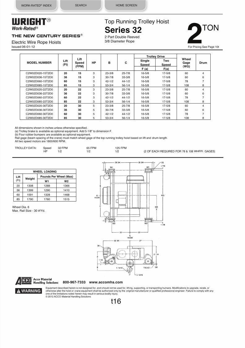
8/21/2019 2013 Wright Specifications Catalog
http://slidepdf.com/reader/full/2013-wright-specifications-catalog 115/189
WORK-RATED® INDEX SEARCH HOME SCREEN
Electric Wire Rope HoistsIssued 06-01-12
Top Running Trolley Hoist
Series 322 Part Double Reeved
3/8 Diameter Rope
MODEL NUMBER
Lift
(Ft)
Lift Speed
(FPM)
HP
B
C
Trolley Drive
Wheel Gage
(WG)
Drum
Single
Two
Speed Speed
F (a) F(a)
C2W02D020-15T2D0 20 15
3
23-3/8
25-7/8
16-5/8
17-5/8
60
4
C2W02D036-15T2D0 36 15
3
30-7/8
33-3/8
16-5/8
17-5/8
60
6
C2W02D060-15T2D0 60 15 3 42-1/2 44-1/2 16-5/8 17-5/8 78 7
C2W02D085-15T2D0 85 15 3 53-3/4 56-1/4 16-5/8 17-5/8 108 8
C2W02D020-22T2D0 20 22 3 23-3/8 25-7/8 16-5/8 17-5/8 60 4
C2W02D036-22T2D0 36 22
3
30-7/8
33-3/8
16-5/8
17-5/8
60
6
C2W02D060-22T2D0 60 22
3
42-1/2
44-1/2
16-5/8
17-5/8
78
7
C2W02D085-22T2D0 85 22 3 53-3/4 56-1/4 16-5/8 17-5/8 108 8
C2W02D020-30T2D0 20 30
5
23-3/8
25-7/8
16-5/8
17-5/8
60
4
C2W02D036-30T2D0 36 30 5 30-7/8 33-3/8 16-5/8 17-5/8 60 6
C2W02D060-30T2D0 60 30 5 42-1/2 44-1/2 16-5/8 17-5/8 78 7
C2W02D085-30T2D0 85 30
5
53-3/4
56-1/4
16-5/8
17-5/8
108
8
All dimensions shown in inches unless otherwise specified.(a) Trolley brake is available as optional equipment. Add 5-1/8" to dimension F.(b) Four rubber bumpers are available as optional equipment.Rail gage (beam spacing of the crane) must match wheel gage of the top running trolley hoist based on lift and drum length.All two speed motors are 1800/600 RPM.
TROLLEY DATA: Speed 32 FPM 65 FPM 125 FPMHP 1/2 1/2 1/2 (2 OF EACH REQUIRED FOR 78 & 108 WHEEL GAGES)
Wheel Dia. 6Max. Rail Size - 30 #/Yd.
t16
Equipment described herein is not designed for, and should not be used for, lift ing, supporting, or transporting humans. Modifications to upgrade, rerate, orotherwise alter the hoist or crane equipment shall be authorized only by the original manufacturer or qualified professional engineer. Failure to comply with anyone of the limitations noted herein may result in serious bodily injury.© 2012 ACCO Material Handling Solutions
800-967-7333 www.accomhs.com
TON 2For Pricing See Page 10t
WHEEL LOADING
Lift (Ft)
Weight Pounds Per Wheel (Max)
W1 W2
20 1308 1288 1366
36 1399 1290 1410
60 1591 1328 1468
85 1790 1760 1515

8/21/2019 2013 Wright Specifications Catalog
http://slidepdf.com/reader/full/2013-wright-specifications-catalog 116/189
WORK-RATED® INDEX SEARCH HOME SCREEN
Electric Wire Rope HoistsIssued 06-01-12
Top Running Trolley Hoist
Series 332 Part Double Reeved
3/8 Diameter Rope
t17
Wheel Dia. 6
Max. Rail Size - 30 #/Yd.
MODEL NUMBER
Lift
(Ft)
Lift
Speed
(FPM) HP
B
C
Trolley Drive
Wheel
Gage
(WG) Drum
Single
Two
Speed Speed
F (a) F (a)
C3W02D020-44T2D0 20 44 7-1/2 21-1/8 23-5/8 16-5/8 17-5/8 60 2
C3W02D036-44T2D0 36 44
7-1/2
26-5/8
29-1/8
16-5/8
17-5/8
60
3
C3W02D054-44T2D0 54 44
7-112
33-1/8
35-5/8
16-5/8
17-5/8
60
4
C3W02D082-44T2D0 82 44
7-1/2
43-1/8
45-5/8
16-5/8
17-5/8
78
5
C3W02D118-44T2D0 118 44 7-1/2 55-5/8 58-1/8 16-5/8 17-5/8 108 6
All dimensions shown in inches unless otherwise specified.(a) Trolley brake is available as optional equipment. Add 5-1/8" to dimension F.(b) Four rubber bumpers are available as optional equipment.Rail gage (beam spacing of the crane) must match wheel gage of the top running trolley hoist based on lift and drum length.All two speed motors are 1800/600 RPM.
TROLLEY DATA: Speed 32 FPM 65 FPM 125 FPMHP 1/2
1/2
1/2 (2 OF EACH REQUIRED FOR 78 & 108 WHEEL GAGES)
Equipment described herein is not designed for, and should not be used for, lifting, supporting, or transporting humans. Modifications to upgrade, rerate, orotherwise alter the hoist or crane equipment shall be authorized only by the original manufacturer or qualified professional engineer. Failure to comply with anyone of the limitations noted herein may result in serious bodily injury.© 2012 ACCO Material Handling Solutions
800-967-7333 www.accomhs.com
TON2For Pricing See Page 10t
WHEEL LOADING
Lift (Ft)
Weight Pounds Per Wheel (Max)
W1 W2
20 1709 1381 1475
36 1803 1382 1520
54
1912
1383 1573
82 2120 1425 1635
118 2426
1639 1900

8/21/2019 2013 Wright Specifications Catalog
http://slidepdf.com/reader/full/2013-wright-specifications-catalog 117/189
WORK-RATED® INDEX SEARCH HOME SCREEN
Electric Wire Rope HoistsIssued 06-01-12
Top Running Trolley Hoist
Series 322 Part Double Reeved
3/8 Diameter Rope
MODEL NUMBER
Lift
(Ft) Lift
Speed
(FPM) HP B C
Trolley Drive
Wheel
Gage
(WG) Drum
Single
Two
Speed Speed
F (a) F (a)
C2W03D020-15T2D0 20 15 3 23-3/8 25-7/8 15-5/8 16-5/8 60 4
C2W03D036-15T2D0 36 15 3 30-7/8 33-3/8 15-5/8 17-5/8 60 6
C2W03D060-15T2D0 60 15
3
42-1/2
44-1/2
15-5/8
17-5/8
78
7
C2W03D085-15T2D0 85 15
3
53-3/4
56-1/4
15-5/8
17-5/8
108
8
C2W03D020-22T2D0 20 22
5
23-3/8
25-7/8
15-5/8
17-5/8
60
4
C2W03D036-22T2D0 36 22
5
30-7/8
33-3/8
15-5/8
17-5/8
60
6
C2W03D060-22T2D0 60 22 5 42-1/2 44-1/2 15-5/8 17-5/8 78 7
C2W03D085-22T2D0 85 22 5 53-3/4 56-1/4 15-5/8 17-5/8 108 8
All dimensions shown in inches unless otherwise specified.(a) Trolley brake is available as optional equipment. Add 5-1/8" to dimension F.(b) Four rubber bumpers are available as optional equipment.Rail gage (beam spacing of the crane) must match wheel gage of the top running trolley hoist based on lift and drum length.All two speed motors are 1800/600 RPM.
TROLLEY DATA: Speed 32 FPM 65 FPM 125 FPMHP 1/2 1/2 1/2 (2 OF EACH REQUIRED FOR 78 & 108 WHEEL GAGES)
Wheel Dia. 6Max. Rail Size - 30 #/Yd.
t18
Equipment described herein is not designed for, and should not be used for, lifting, supporting, or transporting humans. Modifications to upgrade, rerate, orotherwise alter the hoist or crane equipment shall be authorized only by the original manufacturer or qualified professional engineer. Failure to comply with anyone of the limitations noted herein may result in serious bodily injury.© 2012 ACCO Material Handling Solutions
800-967-7333 www.accomhs.com
TON 3For Pricing See Page 11t
WHEEL LOADING
Lift (Ft)
Weight Pounds Per Wheel (Max)
W1 W2
20 1308 1788 1866
36 1399 1790 1910
60 1591 1828 1968
85 1790 1881 2015
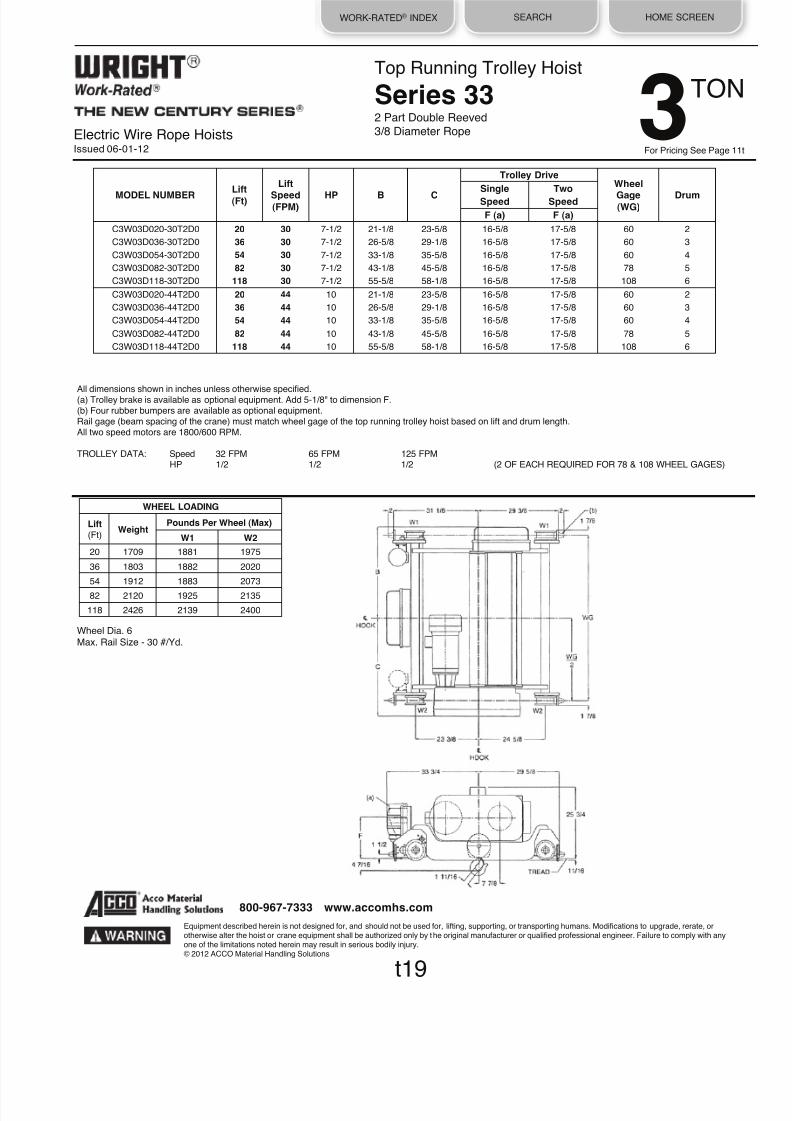
8/21/2019 2013 Wright Specifications Catalog
http://slidepdf.com/reader/full/2013-wright-specifications-catalog 118/189
WORK-RATED® INDEX SEARCH HOME SCREEN
Electric Wire Rope HoistsIssued 06-01-12
Top Running Trolley Hoist
Series 332 Part Double Reeved
3/8 Diameter Rope
Wheel Dia. 6Max. Rail Size - 30 #/Yd.
MODEL NUMBER
Lift
(Ft)
Lift
Speed (FPM)
HP
B
C
Trolley Drive
Wheel
Gage (WG)
Drum
Single Two
Speed
Speed
F (a) F (a)
C3W03D020-30T2D0 20 30 7-1/2 21-1/8 23-5/8 16-5/8 17-5/8 60 2
C3W03D036-30T2D0 36 30
7-1/2
26-5/8
29-1/8
16-5/8
17-5/8
60
3
C3W03D054-30T2D0 54 30 7-1/2 33-1/8 35-5/8 16-5/8 17-5/8 60 4
C3W03D082-30T2D0 82 30 7-1/2 43-1/8 45-5/8 16-5/8 17-5/8 78 5
C3W03D118-30T2D0 118 30
7-1/2
55-5/8
58-1/8
16-5/8
17-5/8
108
6
C3W03D020-44T2D0 20 44 10 21-1/8 23-5/8 16-5/8 17-5/8 60 2
C3W03D036-44T2D0 36 44
10
26-5/8
29-1/8
16-5/8
17-5/8
60
3
C3W03D054-44T2D0 54 44
10
33-1/8
35-5/8
16-5/8
17-5/8
60
4
C3W03D082-44T2D0 82 44 10 43-1/8 45-5/8 16-5/8 17-5/8 78 5
C3W03D118-44T2D0 118 44 10 55-5/8 58-1/8 16-5/8 17-5/8 108 6
t19
All dimensions shown in inches unless otherwise specified.(a) Trolley brake is available as optional equipment. Add 5-1/8" to dimension F.(b) Four rubber bumpers are available as optional equipment.Rail gage (beam spacing of the crane) must match wheel gage of the top running trolley hoist based on lift and drum length.All two speed motors are 1800/600 RPM.
TROLLEY DATA: Speed 32 FPM 65 FPM 125 FPMHP 1/2
1/2
1/2 (2 OF EACH REQUIRED FOR 78 & 108 WHEEL GAGES)
Equipment described herein is not designed for, and should not be used for, lifting, supporting, or transporting humans. Modifications to upgrade, rerate, orotherwise alter the hoist or crane equipment shall be authorized only by the original manufacturer or qualified professional engineer. Failure to comply with anyone of the limitations noted herein may result in serious bodily injury.© 2012 ACCO Material Handling Solutions
800-967-7333 www.accomhs.com
TON3For Pricing See Page 11
WHEEL LOADING
Lift (Ft)
Weight Pounds Per Wheel (Max)
W1 W2
20 1709 1881 1975
36 1803 1882 2020
54 1912 1883 2073
82
2120
1925 2135
118 2426
2139 2400

8/21/2019 2013 Wright Specifications Catalog
http://slidepdf.com/reader/full/2013-wright-specifications-catalog 119/189
WORK-RATED® INDEX SEARCH HOME SCREEN
Electric Wire Rope HoistsIssued 06-01-12
Top Running Trolley Hoist
Series 322 Part Double Reeved
3/8 Diameter Rope
MODEL NUMBER
Lift
(Ft)
Lift Speed
(FPM) HP B C
Trolley Drive
Wheel Gage
(WG) Drum
Single
Two
Speed Speed
F (a) F(a)
C2W05D020-15T2D0 20 15 5 23-3/8 25-7/8 16-5/8 17-5/8 60 4
C2W05D036-15T2D0 36 15 5 30-7/8 33-3/8 16-5/8 17-5/8 60 6
C2W05D060-15T2D0 60 15 5 42-1/2 44-1/2 16-5/8 17-5/8 78 7
C2W05D085-15T2D0 85 15
5
53-3/4
56-1/4
16-5/8
17-5/8
108
8
All dimensions shown in inches unless otherwise specified.(a) Trolley brake is available as optional equipment. Add 5-1/8" to dimension F.(b) Four rubber bumpers are available as optional equipment.Rail gage (beam spacing of the crane) must match wheel gage of the top running trolley hoist based on lift and drum length.All two speed motors are 1800/600 RPM.
TROLLEY DATA: Speed 32 FPM 65 FPM 125 FPMHP 1/2
1/2
1 (2 OF EACH REQUIRED FOR 78 & 108 WHEEL GAGES)
Wheel Dia. 6Max. Rail Size - 30 #/Yd.
t20
Equipment described herein is not designed for, and should not be used for, lifting, supporting, or transporting humans. Modifications to upgrade, rerate, orotherwise alter the hoist or crane equipment shall be authorized only by the original manufacturer or qualified professional engineer. Failure to comply with anyone of the limitations noted herein may result in serious bodily injury.© 2012 ACCO Material Handling Solutions
800-967-7333 www.accomhs.com
TON 5For Pricing See Page 12t
WHEEL LOADING
Lift (Ft)
Weight Pounds Per Wheel (Max)
W1 W2
20
1308
2788
2866
36
1399
2790
2910
60 1591 2828 2968
85 1790 2880 3015

8/21/2019 2013 Wright Specifications Catalog
http://slidepdf.com/reader/full/2013-wright-specifications-catalog 120/189
WORK-RATED® INDEX SEARCH HOME SCREEN
Electric Wire Rope HoistsIssued 06-01-12
Top Running Trolley Hoist
Series 332 Part Double Reeved
3/8 Diameter Rope
Wheel Dia. 6Max. Rail Size - 30 #/Yd.
MODEL NUMBER
Lift
(Ft) Lift
Speed
(FPM) HP B C
Trolley Drive
Wheel
Gage
(WG) Drum
Single
Two
Speed Speed
F (a) F (a)
C3W05D020-22T2D0 20 22
7-1/2
21-1/8
23-5/8
16-5/8
17-5/8
60
2
C3W05D036-22T2D0 36 22 7-1/2 26-5/8 29-1/8 16-5/8 17-5/8 60 3
C3W05D054-22T2D0 54 22 7-112 33-1/8 35-5/8 16-5/8 17-5/8 60 4
C3W05D082-22T2D0 82 22
7-1/2
43-1/8
45-5/8
16-5/8
17-5/8
78
5
C3W03D118-22T2D0 118 22
7-1/2
55-5/8
58-1/8
16-5/8
17-5/8
108
6
C3W05D020-30T2D0 20 30
10
21-1/8
23-5/8
16-5/8
17-5/8
60
2
C3W05D036-30T2D0 36 30
10
26-5/8
29-1/8
16-5/8
17-5/8
60
3
C3W05D054-30T2D0 54 30 10 33-1/8 35-5/8 16-5/8 17-5/8 60 4
C3W05D082-30T2D0 82 30 10 43-1/8 45-5/8 16-5/8 17-5/8 78 5
C3W05D118-30T2D0 118 30
10
55-5/8
58-1/8
16-5/8
17-5/8
108
6
All dimensions shown in inches unless otherwise specified.
(a) Trolley brake is available as optional equipment. Add 5-1/8" to dimension F.(b) Four rubber bumpers are available as optional equipment.Rail gage (beam spacing of the crane) must match wheel gage of the top running trolley hoist based on lift and drum length.All two speed motors are 1800/600 RPM.
TROLLEY DATA: Speed 32 FPM 65 FPM 125 FPMHP 1/2 1/2 1 (2 OF EACH REQUIRED FOR 78 & 108 WHEEL GAGES)
t21
Equipment described herein is not designed for, and should not be used for, lifting, supporting, or transporting humans. Modifications to upgrade, rerate, orotherwise alter the hoist or crane equipment shall be authorized only by the original manufacturer or qualified professional engineer. Failure to comply with anyone of the limitations noted herein may result in serious bodily injury.© 2012 ACCO Material Handling Solutions
800-967-7333 www.accomhs.com
TON5For Pricing See Page 12
WHEEL LOADING
Lift (Ft)
Weight Pounds Per Wheel (Max)
W1 W2
20 1709 2904 2951
36 1803 2880 3022
54 1912 2881 3075
82 2120 2924 3136
118 2426 3001 3212

8/21/2019 2013 Wright Specifications Catalog
http://slidepdf.com/reader/full/2013-wright-specifications-catalog 121/189
WORK-RATED® INDEX SEARCH HOME SCREEN
Electric Wire Rope HoistsIssued 06-01-12
Top Running Trolley Hoist
Series 342 Part Double Reeved
1/2 Diameter Rope
MODEL NUMBER
Lift
(Ft) Lift
Speed
(FPM) HP B C J K
Trolley Drive
Wheel
Gage
(WG) Drum
Single
Two
Speed Speed
F (a) F (a)
C4W05D020-44T2D0 20 44 15 24-1/8 30-3/4 13-1/2 13-1/2 17-5/8 18-5/8 60 2
C4W05D031-44T2D0 31 44 15 28-5/8 35-1/4 9 9 17-5/8 18-5/8 60 3
C4W05D047-44T2D0 47 44 15 34-5/8 41-1/4 12 12 17-5/8 18-5/8 78 4
C4W05D076-44T2D0 76 44
15
45-5/8
52-1/4
10
10
17-5/8
18-5/8
96
5
C4W05D115-44T2D0 115 44
15
60-5/8
67-1/4
7
7
17-5/8
18-5/8
120
6
All dimensions shown in inches unless otherwise specified.(a) Trolley brake is available as optional equipment. Add 5-1/8" to dimension F.(b) Four rubber bumpers are available as optional equipment.Rail gage (beam spacing of the crane) must match wheel gage of the top running trolley hoist based on lift and drum length.All two speed motors are 1800/600 RPM.
TROLLEY DATA: Speed 32 FPM 65 FPM 125 FPMHP 1/2 1/2 1/2 (2 OF EACH REQUIRED FOR 78, 96 & 120 WHEEL GAGES)
Wheel Dia. 8
Max. Rail Size - 30 #/Yd.
t22
Equipment described herein is not designed for, and should not be used for, lifting, supporting, or transporting humans. Modifications to upgrade, rerate, orotherwise alter the hoist or crane equipment shall be authorized only by the original manufacturer or qualified professional engineer. Failure to comply with anyone of the limitations noted herein may result in serious bodily injury.© 2012 ACCO Material Handling Solutions
800-967-7333 www.accomhs.com
TON 5For Pricing See Page 12t
WHEEL LOADING
Lift (Ft)
Weight Pounds Per Wheel (Max)
W1 W2
20 3330 3196 3469
31
3450
3189
3536
47 3744 3265 3607
76 4154 3342 3737
115 4712 3454 3902

8/21/2019 2013 Wright Specifications Catalog
http://slidepdf.com/reader/full/2013-wright-specifications-catalog 122/189
WORK-RATED® INDEX SEARCH HOME SCREEN
Electric Wire Rope HoistsIssued 06-01-12
Top Running Trolley Hoist
Series 334 Part Double Reeved
3/8 Diameter Rope
Wheel Dia. 6Max. Rail Size - 30 #/Yd.
MODEL NUMBER
Lift
(Ft)
Lift
Speed
(FPM) HP
B
C
D
Trolley Drive
Wheel
Gage
(WG) Drum
Single
Two
Speed Speed
F (a) F (a)
C3W07D022-15T4D0 22 15
7-1/2
33-1/8
35-5/8
27-3/4
16-5/8
17-5/8
60
4
C3W07D036-15T4D0 36 15
7-1/2
43-1/8
45-5/8
30
16-5/8
17-5/8
78
5
C3W07D054-15T4D0 54 15 7-1/2 55-5/8 58-1/8 30 16-5/8 17-5/8 108 6
C3W07D022-22T4D0 22 22
10
33-1/8
35-5/8
27-3/4
16-5/8
17-5/8
60
4
C3W07D036-22T4D0 36 22 10 43-1/8 45-5/8 30 16-5/8 17-5/8 78 5
C3W07D054-22T4D0 54 22 10 55-5/8 58-1/8 30 16-5/8 17-5/8 108 6
All dimensions shown in inches unless otherwise specified.(a) Trolley brake is available as optional equipment. Add 5-1/8" to dimension F.(b) Four rubber bumpers are available as optional equipment.Rail gage (beam spacing of the crane) must match wheel gage of the top running trolley hoist based on lift and drum length.All two speed motors are 1800/600 RPM.
TROLLEY DATA: Speed 32 FPM 65 FPM 125 FPMHP 1/2 1/2 1 (2 OF EACH REQUIRED FOR 78 & 108 WHEEL GAGES)
t23
Equipment described herein is not designed for, and should not be used for, lifting, supporting, or transporting humans. Modifications to upgrade, rerate, orotherwise alter the hoist or crane equipment shall be authorized only by the original manufacturer or qualified professional engineer. Failure to comply with anyone of the limitations noted herein may result in serious bodily injury.© 2012 ACCO Material Handling Solutions
800-967-7333 www.accomhs.com
For Pricing See Page 13t
TON71
2
WHEEL LOADING
Lift (Ft)
Weight Pounds Per Wheel (Max)
W1 W2
22 2008 4155 4349
36 2225 4199 4414
54 2529
4275 4496

8/21/2019 2013 Wright Specifications Catalog
http://slidepdf.com/reader/full/2013-wright-specifications-catalog 123/189
WORK-RATED® INDEX SEARCH HOME SCREEN
Electric Wire Rope HoistsIssued 06-01-12
Top Running Trolley Hoist
Series 342 Part Double Reeved
1/2 Diameter Rope
MODEL NUMBER
Lift
(Ft) Lift
Speed
(FPM) HP B C J K
Trolley Drive
Wheel
Gage
(WG) Drum
Single
Two
Speed Speed
F (a) F (a)
C4W07D020-30T2D0 20 30 15 24-1/8 30-3/4 13-1/2 13-1/2 17-5/8 18-5/8 60 2
C4W07D031-30T2D0 31 30
15
28-5/8
35-1/4
9
9
17-5/8
18-5/8
60
3
C4W07D047-30T2D0 47 30
15
34-5/8
41-1/4
12
12
17-5/8
18-5/8
78
4
C4W07D076-30T2D0 76 30
15
45-5/8
52-1/4
10
10
17-5/8
18-5/8
96
5
C4W07D115-30T2D0 115 30 15 60-5/8 67-1/4 7 7 17-5/8 18-5/8 120 6
All dimensions shown in inches unless otherwise specified.(a) Trolley brake is available as optional equipment. Add 5-1/8" to dimension F.(b) Four rubber bumpers are available as optional equipment.Rail gage (beam spacing of the crane) must match wheel gage of the top running trolley hoist based on lift and drum length.All two speed motors are 1800/600 RPM.
TROLLEY DATA: Speed 32 FPM 65 FPM 125 FPMHP 1/2 1/2 1/2 (2 OF EACH REQUIRED FOR 78, 96 & 120 WHEEL GAGES)
Wheel Dia. 8
Max. Rail Size - 30 #/Yd.
t24
Equipment described herein is not designed for, and should not be used for, lifting, supporting, or transporting humans. Modifications to upgrade, rerate, orotherwise alter the hoist or crane equipment shall be authorized only by the original manufacturer or qualified professional engineer. Failure to comply with anyone of the limitations noted herein may result in serious bodily injury.© 2012 ACCO Material Handling Solutions
800-967-7333 www.accomhs.com
For Pricing See Page 13t
TON 71
2
WHEEL LOADING
Lift (Ft)
Weight Pounds Per Wheel (Max)
W1 W2
20
3330
4446
4719
31
3450
4439
4786
47
3744
4515
4857
76
4154
4592
4987
115 4712 4704 5152
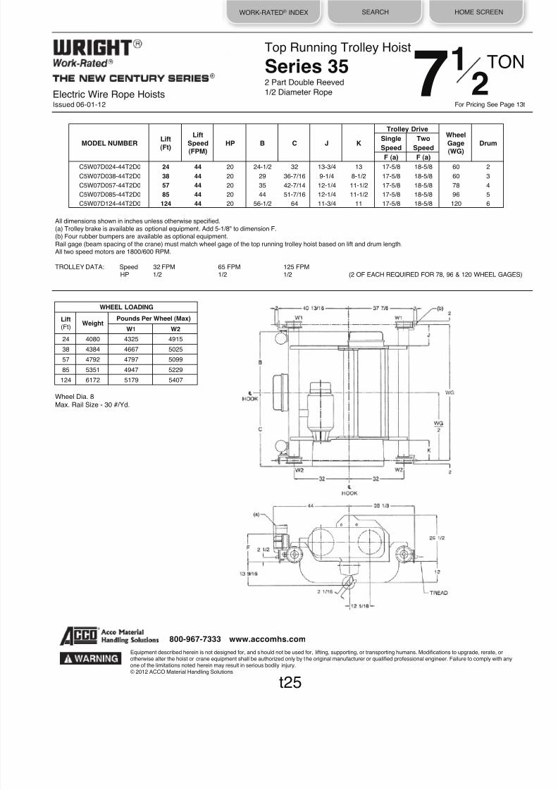
8/21/2019 2013 Wright Specifications Catalog
http://slidepdf.com/reader/full/2013-wright-specifications-catalog 124/189
WORK-RATED® INDEX SEARCH HOME SCREEN
Electric Wire Rope HoistsIssued 06-01-12
Top Running Trolley Hoist
Series 352 Part Double Reeved
1/2 Diameter Rope
Wheel Dia. 8Max. Rail Size - 30 #/Yd.
MODEL NUMBER
Lift
(Ft) Lift
Speed
(FPM) HP B C J K
Trolley Drive
Wheel
Gage
(WG) Drum
Single
Two
Speed Speed
F (a) F (a)
C5W07D024-44T2D0 24 44
20
24-1/2
32
13-3/4
13
17-5/8
18-5/8
60
2
C5W07D038-44T2D0 38 44
20
29
36-7/16
9-1/4
8-1/2
17-5/8
18-5/8
60
3
C5W07D057-44T2D0 57 44 20 35 42-7/14 12-1/4 11-1/2 17-5/8 18-5/8 78 4
C5W07D085-44T2D0 85 44
20
44
51-7/16
12-1/4
11-1/2
17-5/8
18-5/8
96
5
C5W07D124-44T2D0 124 44
20
56-1/2
64
11-3/4
11
17-5/8
18-5/8
120
6
All dimensions shown in inches unless otherwise specified.(a) Trolley brake is available as optional equipment. Add 5-1/8" to dimension F.(b) Four rubber bumpers are available as optional equipment.
Rail gage (beam spacing of the crane) must match wheel gage of the top running trolley hoist based on lift and drum length.All two speed motors are 1800/600 RPM.
TROLLEY DATA: Speed 32 FPM 65 FPM 125 FPM
HP 1/2
1/2
1/2 (2 OF EACH REQUIRED FOR 78, 96 & 120 WHEEL GAGES)
t25
Equipment described herein is not designed for, and should not be used for, lifting, supporting, or transporting humans. Modifications to upgrade, rerate, orotherwise alter the hoist or crane equipment shall be authorized only by the original manufacturer or qualified professional engineer. Failure to comply with anyone of the limitations noted herein may result in serious bodily injury.© 2012 ACCO Material Handling Solutions
800-967-7333 www.accomhs.com
For Pricing See Page 13
TON71
2
WHEEL LOADING
Lift (Ft)
Weight Pounds Per Wheel (Max)
W1 W2
24
4080
4325
4915
38
4384
4667
5025
57
4792
4797
5099
85 5351 4947 5229
124 6172 5179 5407

8/21/2019 2013 Wright Specifications Catalog
http://slidepdf.com/reader/full/2013-wright-specifications-catalog 125/189
WORK-RATED® INDEX SEARCH HOME SCREEN
Electric Wire Rope HoistsIssued 06-01-12
Top Running Trolley Hoist
Series 334 Part Double Reeved
3/8 Diameter Rope
MODEL NUMBER
Lift
(Ft) Lift
Speed
(FPM) HP B C D
Trolley Drive
Wheel
Gage
(WG) Drum
Single
Two
Speed Speed
F (a) F (a)
C3W10D022-15T4D0 22 15 10 33-1/8 35-5/8 27-3/4 16-5/8 17-5/8 60 4
C3W10D036-15T4D0 36 15
10
43-1/8
45-5/8
30
16-5/8
17-5/8
78
5
C3W10D054-15T4D0 54 15
10
55-5/8
58-1/8
30
16-5/8
17-5/8
108
6
All dimensions shown in inches unless otherwise specified.(a) Trolley brake is available as optional equipment. Add 5-1/8" to dimension F.(b) Four rubber bumpers are available as optional equipment.Rail gage (beam spacing of the crane) must match wheel gage of the top running trolley hoist based on lift and drum length.All two speed motors are 1800/600 RPM.
TROLLEY DATA: Speed 32 FPM 65 FPM 125 FPMHP 1/2 1 1 (2 OF EACH REQUIRED FOR 78 & 108 WHEEL GAGES)
Wheel Dia. 6Max. Rail Size - 30 #/Yd.
t26
Equipment described herein is not designed for, and should not be used for, lifting, supporting, or transporting humans. Modifications to upgrade, rerate, orotherwise alter the hoist or crane equipment shall be authorized only by the original manufacturer or qualified professional engineer. Failure to comply with anyone of the limitations noted herein may result in serious bodily injury.
© 2012 ACCO Material Handling Solutions
800-967-7333 www.accomhs.com
TON 10For Pricing See Page 14t
WHEEL LOADING
Lift (Ft)
Weight Pounds Per Wheel (Max)
W1 W2
22
2008
5405
5599
36
2225
5449
5664
54 2529
5525 5746

8/21/2019 2013 Wright Specifications Catalog
http://slidepdf.com/reader/full/2013-wright-specifications-catalog 126/189
WORK-RATED® INDEX SEARCH HOME SCREEN
Electric Wire Rope HoistsIssued 06-01-12
Top Running Trolley Hoist
Series 344 Part Double Reeved
1/2 Diameter Rope
Wheel Dia. 8
Max. Rail Size - 30 #/Yd.
MODEL NUMBER
Lift (Ft)
Lift
Speed
(FPM) HP
B
C
J
K
Trolley Drive
Wheel
Gage
(WG) Drum
Single
Two
Speed Speed
F (a) F (a)
C4W10D020-22T4D0 20 22 15 34-5/8 41-1/4 12 12 17-5/8 18-5/8 78 4
C4W10D035-22T4D0 35 22
15
45-5/8
52-1/4
10
10
17-5/8
18-5/8
96
5
C4W10D054-22T4D0 54 22
15
60-5/8
67-1/4
7
7
17-5/8
18-5/8
120
6
All dimensions shown in inches unless otherwise specified.(a) Trolley brake is available as optional equipment. Add 5-1/8" to dimension F.(b) Four rubber bumpers are available as optional equipment.Rail gage (beam spacing of the crane) must match wheel gage of the top running trolley hoist based on lift and drum length.All two speed motors are 1800/600 RPM.
TROLLEY DATA: Speed 32 FPM 65 FPM 125 FPMHP 1/2 1/2 1 (2 OF EACH REQUIRED FOR ALL WHEEL GAGES)
t27
Equipment described herein is not designed for, and should not be used for, lifting, supporting, or transporting humans. Modifications to upgrade, rerate, orotherwise alter the hoist or crane equipment shall be authorized only by the original manufacturer or qualified professional engineer. Failure to comply with anyone of the limitations noted herein may result in serious bodily injury.
© 2012 ACCO Material Handling Solutions
800-967-7333 www.accomhs.com
TON10For Pricing See Page 14t
WHEEL LOADING
Lift (Ft)
Weight Pounds Per Wheel (Max)
W1 W2
20
4002
5831
6170
35
4454
5919
6308
54 5167 6076 6512

8/21/2019 2013 Wright Specifications Catalog
http://slidepdf.com/reader/full/2013-wright-specifications-catalog 127/189
WORK-RATED® INDEX SEARCH HOME SCREEN
Electric Wire Rope HoistsIssued 06-01-12
Top Running Trolley Hoist
Series 352 Part Double Reeved
1/2 Diameter Rope
MODEL NUMBER
Lift
(Ft) Lift
Speed
(FPM) HP B C J K
Trolley Drive
Wheel
Gage
(WG) Drum
Single
Two
Speed Speed
F (a) F (a)
C5W10D024-30T2D0 24 30 20 24-1/2 32 13-3/4 13 15-7/8 18-3/8 60 2
C5W10D038-30T2D0 38 30
20
29
36-7/16
9-1/4
8-1/2
15-7/8
18-3/8
60
3
C5W10D057-30T2D0 57 30
20
35
42-7/16
12-1/4
11-1/2
15-7/8
18-3/8
78
4
C5W10D085-30T2D0 85 30 20 44 51-7/16 12-1/4 11-1/2 15-7/8 18-3/8 96 5
C5W10D124-30T2D0 124 30 20 56-1/2 64 11-3/4 11 17-5/8 18-5/8 120 6
All dimensions shown in inches unless otherwise specified.(a) Trolley brake is available as optional equipment. Add 5-1/8" to dimension F.(b) Four rubber bumpers are available as optional equipment.Rail gage (beam spacing of the crane) must match wheel gage of the top running trolley hoist based on lift and drum length.All two speed motors are 1800/600 RPM.
TROLLEY DATA: Speed 32 FPM 65 FPM 125 FPMHP 1/2 1/2 1 (2 OF EACH REQUIRED FOR 78, 96 & 120 WHEEL GAGES)
Wheel Dia. 8Max. Rail Size - 30 #/Yd.
t28
Equipment described herein is not designed for, and should not be used for, lifting, supporting, or transporting humans. Modifications to upgrade, rerate, orotherwise alter the hoist or crane equipment shall be authorized only by the original manufacturer or qualified professional engineer. Failure to comply with anyone of the limitations noted herein may result in serious bodily injury.© 2012 ACCO Material Handling Solutions
800-967-7333 www.accomhs.com
TON 10For Pricing See Page 14t
WHEEL LOADING
Lift (Ft)
Weight Pounds Per Wheel (Max)
W1 W2
24
4080
5875
6165
38
4384
5917
6275
57
4792
6047
6349
85 5351 6198 6478
124 6172 6429 6657

8/21/2019 2013 Wright Specifications Catalog
http://slidepdf.com/reader/full/2013-wright-specifications-catalog 128/189
WORK-RATED® INDEX SEARCH HOME SCREEN
Electric Wire Rope HoistsIssued 06-01-12
Top Running Trolley Hoist
Series 344 Part Double Reeved
1/2 Diameter Rope
Wheel Dia. 8
Max. Rail Size - 30 #/Yd.
MODEL NUMBER
Lift
(Ft) Lift
Speed
(FPM) HP B C J K
Trolley Drive
Wheel
Gage
(WG) Drum
Single
Two
Speed Speed
F (a) F (a)
C4W15D020-15T4D0 20 15 15 34-5/8 41-1/4 12 12 17-5/8 18-5/8 78 4
C4W15D035-15T4D0 35 15
15
45-5/8
52-1/4
10
10
17-5/8
18-5/8
96
5
C4W15D054-15T4D0 54 15
15
60-5/8
67-1/4
7
7
17-5/8
18-5/8
120
6
All dimensions shown in inches unless otherwise specified.(a) Trolley brake is available as optional equipment. Add 5-1/8" to dimension F.(b) Four rubber bumpers are available as optional equipment.Rail gage (beam spacing of the crane) must match wheel gage of the top running trolley hoist based on lift and drum length.All two speed motors are 1800/600 RPM.
TROLLEY DATA: Speed 32 FPM 65 FPM 125 FPMHP 1/2 1/2 1 (2 OF EACH REQUIRED FOR ALL WHEEL GAGES)
t29
Equipment described herein is not designed for, and should not be used for, lifting, supporting, or transporting humans. Modifications to upgrade, rerate, orotherwise alter the hoist or crane equipment shall be authorized only by the original manufacturer or qualified professional engineer. Failure to comply with anyone of the limitations noted herein may result in serious bodily injury.© 2012 ACCO Material Handling Solutions
800-967-7333 www.accomhs.com
TON15For Pricing See Page 15
WHEEL LOADING
Lift (Ft)
Weight Pounds Per Wheel (Max)
W1 W2
20
4002
8331
8670
35
4454
8419
8808
54 5167 8576 9012

8/21/2019 2013 Wright Specifications Catalog
http://slidepdf.com/reader/full/2013-wright-specifications-catalog 129/189
WORK-RATED® INDEX SEARCH HOME SCREEN
Electric Wire Rope HoistsIssued 06-01-12
Top Running Trolley Hoist
Series 354 Part Double Reeved
1/2 Diameter Rope
MODEL NUMBER
Lift (Ft)
Lift Speed
(FPM)
HP
B
C
D
J
K
Trolley Drive
Wheel Gage
(WG)
Drum
Single
Two
Speed Speed
F (a) F (a)
C5W15D024-22T4D0 24 22 20 35 42-7/16 26-1/2 12-1/4 11-1/2 17-5/8 18-5/8 78 4
C5W15D039-22T4D0 39 22
20
44
51-7/16
26-3/4
12-1/4
11-1/2
17-5/8
18-5/8
96
5
C5W15D058-22T4D0 58 22 20 56-3/8 64 26-3/4 11-3/4 10-15/16 17-5/8 18-5/8 120 6
All dimensions shown in inches unless otherwise specified.(a) Trolley brake is available as optional equipment. Add 5-1/8" to dimension F.(b) Four rubber bumpers are available as optional equipment.Rail gage (beam spacing of the crane) must match wheel gage of the top running trolley hoist based on lift and drum length.All two speed motors are 1800/600 RPM.
TROLLEY DATA: Speed 32 FPM 65 FPM 125 FPMHP 1/2
1/2
1 (2 OF EACH REQUIRED FOR ALL WHEEL GAGES)
Wheel Dia. 8Max. Rail Size - 30 #/Yd.
t30
Equipment described herein is not designed for, and should not be used for, lifting, supporting, or transporting humans. Modifications to upgrade, rerate, orotherwise alter the hoist or crane equipment shall be authorized only by the original manufacturer or qualified professional engineer. Failure to comply with anyone of the limitations noted herein may result in serious bodily injury.© 2012 ACCO Material Handling Solutions
800-967-7333 www.accomhs.com
TON 15For Pricing See Page 15t
WHEEL LOADING
Lift (Ft)
Weight Pounds Per Wheel (Max)
W1 W2
24 5062 8614 8917
39 5693 8791 9056
58 6532 8751 9515

8/21/2019 2013 Wright Specifications Catalog
http://slidepdf.com/reader/full/2013-wright-specifications-catalog 130/189
WORK-RATED® INDEX SEARCH HOME SCREEN
Electric Wire Rope HoistsIssued 06-01-12
Top Running Trolley Hoist
Series 354 Part Double Reeved
1/2 Diameter Rope
Wheel Dia. 8Max. Rail Size - 30 #/Yd.
MODEL NUMBER
Lift (Ft)
Lift
Speed
(FPM) HP
B
C
D
J
K
Trolley Drive
Wheel
Gage
(WG) Drum
Single
Two
Speed Speed
F (a) F (a)
C5W20D024-15T4D0 24 15
20
35
42-7/16
26-1/2
12-1/4
11-1/2
17-5/8
18-5/8
78
4
C5W20D039-15T4D0 39 15 20 44 51-7/16 26-3/4 12-1/4 11-1/2 17-5/8 18-5/8 96 5
C5W20D058-15T4D0 58 15 20 56-3/8 64 26-3/4 11-3/4 10-15/16 17-5/8 18-5/8 120 6
All dimensions shown in inches unless otherwise specified.(a) Trolley brake is available as optional equipment. Add 5-1/8" to dimension F.(b) Four rubber bumpers are available as optional equipment.Rail gage (beam spacing of the crane) must match wheel gage of the top running trolley hoist based on lift and drum length.All two speed motors are 1800/600 RPM.
TROLLEY DATA: Speed 32 FPM 65 FPM 125 FPMHP 1/2
1
N.A. (2 OF EACH REQUIRED FOR ALL WHEEL GAGES)
t31
Equipment described herein is not designed for, and should not be used for, lifting, supporting, or transporting humans. Modifications to upgrade, rerate, orotherwise alter the hoist or crane equipment shall be authorized only by the original manufacturer or qualified professional engineer. Failure to comply with anyone of the limitations noted herein may result in serious bodily injury.© 2012 ACCO Material Handling Solutions
800-967-7333 www.accomhs.com
TON20For Pricing See Page 16
WHEEL LOADING
Lift (Ft)
Weight Pounds Per Wheel (Max)
W1 W2
24
5062
11114
11417
39
5693
11295
11556
58 6532 11251 12015

8/21/2019 2013 Wright Specifications Catalog
http://slidepdf.com/reader/full/2013-wright-specifications-catalog 131/189
WORK-RATED® INDEX SEARCH HOME SCREEN
Electric Wire Rope HoistsIssued 06-01-12
Top Running Trolley Hoist
Series 354 Part Double Reeved
9/16 Diameter Rope
t32
Equipment described herein is not designed for, and should not be used for, lifting, supporting, or transporting humans. Modifications to upgrade, rerate, orotherwise alter the hoist or crane equipment shall be authorized only by the original manufacturer or qualified professional engineer. Failure to comply with anyone of the limitations noted herein may result in serious bodily injury.© 2012 ACCO Material Handling Solutions
800-967-7333 www.accomhs.com
Wheel Dia. 8Max. Rail Size - 30 #/Yd.
MODEL NUMBER
Lift
(Ft) Lift
Speed
(FPM)
HP B C D J K
Trolley Drive
Wheel Gage
(WG)
Drum
Single
Two
Speed Speed
F (a) F (a)
C5W25D020-12T4D0 20 12 20 34-1/8 43-9/16 26-1/2 13-3/16 10-9/16 15-7/8 18-3/8 78 4
C5W25D032-12T4D0 32 12
20
43-1/8
52-1/4
26-1/2
13-3/16
10-9/16
15-7/8
18-3/8
96
5
C5W25D048-12T4D0 48 12
20
55-11/16
65-1/16
26-7/8
12-11/16
10-1/16
15-7/8
18-3/8
120
6
All dimensions shown in inches unless otherwise specified.(a) Trolley brake is available as optional equipment. Add 5-1/8" to dimension F.(b) Four rubber bumpers are available as optional equipment.Rail gage (beam spacing of the crane) must match wheel gage of the top running trolley hoist based on lift and drum length.All two speed motors are 1800/600 RPM.
TROLLEY DATA: Speed 32 FPM 65 FPM 125 FPMHP 1/2
1
N.A. (2 OF EACH REQUIRED FOR ALL WHEEL GAGES)
TON 25For Pricing See Page 17t
WHEEL LOADING
Lift (Ft)
Weight Pounds Per Wheel (Max)
W1 W2
20
5768
13746
14164
32
6250
13849
14301
48 6913 13990 14491

8/21/2019 2013 Wright Specifications Catalog
http://slidepdf.com/reader/full/2013-wright-specifications-catalog 132/189
WORK-RATED® INDEX SEARCH HOME SCREEN
Equipment described herein is not designed for, and should not be used for, lifting, supporting, or transporting humans. Modifications to upgrade, rerate, orotherwise alter the hoist or crane equipment shall be authorized only by the original manufacturer or qualified professional engineer. Failure to comply with anyone of the limitations noted herein may result in serious bodily injury.© 2012 ACCO Material Handling Solutions
800-967-7333 www.accomhs.com
Electric Wire Rope HoistsIssued 06-01-12
Wright family of Work-Rated hoists is a complete line of electric wire rope
hoists. It is an advanced design incorporating the most recent materials and
concept. The most current duty cycle and safety requirements of users arebuilt into this line, not added on.
CONSTRUCTION FEATURES:
The new style of deck mounted Work-rated hoist has been designed to allow
for easy mounting of the hoist to a double beam trolley frame.
CONTROLS: Choose from single, 2-speed, or inverter. Controls aremagnetic reversing type, mechanically and electrically interlocked with 115
volt control circuit. All wiring conforms to applicable NEC requirements.Motor thermostats are standard providing motor running overcurrent
protection. NEMA Type 3R enclosures are standard. Cover is lightweight,tough ABS material, deep-drawn for maximum control accessibility. Controls
are shipped loose for customer mounting.
PUSH BUTTON STATION: Push button stations are not furnished as
standard equipment with these hoists. Push button station drop of cord &strain chain are available as optional equipment. See Accessories Section.Specify required drop.
MOTOR: Standard NEMA C face mounting, TENV, Class F insulation, 30-
minute duty motor is provided for standard commercial power supplies. The
motor has a standard NEMA shall extension.
GEAR TRAIN: Quiet, helical and spur gearing. All gears are machine cut,
case-hardened alloy steel with shock-resistant ductile cores. Gearing isdesigned to AGMA standards for maximum life, and operates in an oil bath.
Rugged aluminum alloy housingprovides rapid heat dissipation.
BEARINGS - SPIDER RETAINERS: Precision heavy-duty ball bearings
support all shafts. All bearings are either splash lubricated, or lifetime pre-lubricated and sealed. Bearings at outboard end of shafts are held in place
by heavy-duty Spider Retainers. This allows removal of Gear Housing Coverfor inspection (after draining oil). All internal parts remain in place and can be
operated for inspection.
DRUM: The large diameter steel drum has machined grooves and large
flanges. At least two full turns of rope remain on the drum at the lowest hookposition of rated lift.
LOAD BLOCK - HOOK: Drop forged heat-treated steel hook swivels 360˚
on a shielded roller thrust bearing and comes equipped with a spring latch.Work can be performed on the load block without removing wire rope from
drum. Sheaves are machined steel.
WIRE ROPE: Pre-formed wire rope, of hoisting service construction, made
of extra improved plow steel (XIP) wi th an independent wire rope center. Hasswaged fittings on both ends for ease of replacement if necessary.
MECHANICAL LOAD BRAKE: Automatic Weston-type multiple disc bra
can hold a full capacity load independent of motor brake. This brake
assures that load does not accelerate while being lowered. No wearcompensation adjustment is required.
MOTOR BRAKE: Proven in millions of hours of in-service operation, theoriginal Wright rectified D-C magnet-actuated disc brake delivers rapid
stops with virtually no hook drift. Rated a minimum of 150% of full load
motor torque. Exclusive brake-sensing microswitch prevents motor fromoperating against engaged brake and when brake requires adjustment.
LIMIT SWITCH: A gravity-type upper hook travel limit switch is provided.
The unit is equipped with an automatic momentary lowering circuit. Anoptional geared limit switch is also available.
OVERLOAD CUTOFF: Exclusive patented ACCO unit is standard on all
Work-rated hoists except single-line models. The overload limiting deviceshall be designed to permit operation of the hoist within its rated load and
limit the amount of overload that can be lifted by a properly maintained
hoist, under normal operating conditions.
The overload limiting device may allow the lift ing of an overload, but shal
be designed to prevent the lifting of an overload of such magnitude thatcould cause damage to a hoist, trolley, or supports. This does not imply t
any overload is to be intentionally applied to the hoist.
The overload limiting device is an emergency device and shall not be useto measure the maximum load to be lifted and shall not be used to sense
the overload imposed by the constrained load.
HOW TO SPECIFY Work-Rated DECK MOUNTED HOISTS
1. DETERMINE PROPER MODEL NUMBER in regard to hoist capacity,
lifting speed, and hoist control found in the following pages. Deck mountehoists are grouped by load capacity and shown in top corner of each pag
2. SPECIFY MOTOR VOLTAGE: Wright standard motors are available in200/230/460/575-3-60 power with Class F insulation, and are totallyenclosed non-ventilated. Control is furnished as standard equipment.
Additional motor and control accessories are found in the AccessoriesSection.
3. DETERMINE ADDITIONAL MODIFICATIONS AND ACCESSORIES.
The check list and descriptive data for these i tems are found in theAccessories Section.
4. ACCO RESERVES THE RIGHT TO MAKE CHANGES TO THIS
CATALOG AS MAYBE DEEMED NECESSARY.
Deck MountedFeatures & Benefits 1TO 25 TON

8/21/2019 2013 Wright Specifications Catalog
http://slidepdf.com/reader/full/2013-wright-specifications-catalog 133/189
WORK-RATED® INDEX SEARCH HOME SCREEN
Electric Wire Rope HoistsIssued 06-01-12
Another word is "part" which refers to the mechanical advantage gained by
multiple reeving. For example, with 2 part single reeving (2 PS) the load isdistributed over the two parts and the mechanical advantage doubles thecapacity of one part reeving and reduces by one half the lifting or lowering
speed of the hook.
Reeving changes hoist arrangement to the beam or track, minimumheadroom distance, and lateral hook travel.
Deck MountedFeatures & Benefits 1TO 25 TON
Some applications require that the load, when being lif ted, not move right or
left from hoist centerline. If this requirement is known, a true vertical lift hoistmust be used. These are described as two part double (2 PD) or four part
double (4 PD).
Single Reeved
Double Reeved
Reeving: 2 PS or 4 PS 2 PD or 4 PD
Minimum
Fair
Good
Headroom:
Lateral
Hook travels
None
Hook Travel:
Cost:
Lower
Higher
Equipment described herein is not designed for, and should not be used for, lifting, supporting, or transporting humans. Modifications to upgrade, rerate, orotherwise alter the hoist or crane equipment shall be authorized only by the original manufacturer or qualified professional engineer. Failure to comply with anyone of the limitations noted herein may result in serious bodily injury.© 2012 ACCO Material Handling Solutions
800-967-7333 www.accomhs.com
HEADROOM: Some applications require that the distance from the
bottom of beam to saddle of the hook be held to a minimum. Thisdimension will determine whether single reeved or double reeved model
is required.
3. SPECIFY PROPER MODEL NUMBER in regard to hoist.Capacity, lifting speed, mounting and hoist control found in the
following pages.
4. SPECIFY MOTOR VOLTAGE: Wright standard motors areavailable in 200/230/460/575-3-60 power with Class F insulation,
and are totally enclosed non-ventilated. Control is furnished asstandard equipment. Additional motor and control accessories are
found in the Accessories Section.
5. SPECIFY OTHER MODIFICATIONS AND ACCESSORIES.
6. SPECIAL APPLICATION HOISTS: Contact your nearest Wright
representative.
7. ACCO RESERVES THE RIGHT TO MAKE CHANGES TO
THIS CATALOG AS MAY BE DEEMED NECESSARY.

8/21/2019 2013 Wright Specifications Catalog
http://slidepdf.com/reader/full/2013-wright-specifications-catalog 134/189
WORK-RATED® INDEX SEARCH HOME SCREEN
Electric Wire Rope HoistsIssued 06-01-12
Deck Mounted
Series 322 Part Single Reeved
3/8 Diameter Rope
TON 1For Pricing See Page 1d
d1
Equipment described herein is not designed for, and should not be used for, lifting, supporting, or transporting humans. Modifications to upgrade, rerate, orotherwise alter the hoist or crane equipment shall be authorized only by the original manufacturer or qualified professional engineer. Failure to comply with anyone of the limitations noted herein may result in serious bodily injury.© 2012 ACCO Material Handling Solutions
800-967-7333 www.accomhs.com
All dimensions shown in inches unless otherwise specified.Controls are factory mounted and wired.
MOUNTING DATA
Load In Pounds Per Side
Lift W1 W2
(Ft) Lower Upper Lower Upper
17 1433 870 1205 1768
33 1373 671 1311 2013
51 1350 567 1387 2170
83 1310 440 1519 2389
MODEL NUMBER
Lift (Ft)
Lift
Speed
(FPM) HP
B
C
D
Hook Travel
Weight
Drum
L U
C2W01S017-15D2S0 17 15 3 15-5/8 17-3/8 8 1-13/16 2-11/16 638 1
C2W01S033-15D2S0 33 15 3 19-3/8 21-1/8 11-3/4 1-13/16 6-7/16 684 3
C2W01S051-15D2S0 51 15
3 23-3/4 25-1/2 16-1/8 1-13/16 10-13/16 737 4
C2W01S083-15D2S0 83 15
3 31-1/4 33 23-5/8 1-13/16 18-5/16 829 6
C2W01S017-22D2S0 17 22
3 15-5/8 17-3/8 8 1-13/16 2-11/16 638 1
C2W01S033-22D2S0 33 22
3 19-3/8 21-1/8 11-3/4 1-13/16 6-7/16 684 3
C2W01S051-22D2S0 51 22 3 23-3/4 25-1/2 16-1/8 1-13/16 10-13/16 737 4
C2W01S083-22D2S0 83 22 3 31-1/4 33 23-5/8 1-13/16 18-5/16 829 6
C2W01S017-30D2S0 17 30 3 15-5/8 17-3/8 8 1-13/16 2-11/16 638 1
C2W01S033-30D2S0 33 30 3 19-3/8 21-1/8 11-3/4 1-13/16 6-7/16 684 3
C2W01S051-30D2S0 51 30
3 23-3/4 25-1/2 16-1/8 1-13/16 10-13/16 737 4
C2W01S083-30D2S0 83 30 3 31-1/4 33 23-5/8 1-13/16 18-5/16 829 6

8/21/2019 2013 Wright Specifications Catalog
http://slidepdf.com/reader/full/2013-wright-specifications-catalog 135/189
WORK-RATED® INDEX SEARCH HOME SCREEN
Electric Wire Rope HoistsIssued 06-01-12
Deck Mounted
Series 332 Part Single Reeved
1/2 Diameter Rope
MODEL NUMBER
Lift (Ft)
Lift
Speed
(FPM) HP
B
C
D
Hook Travel
Weight
Drum L U
C3W01S017-44D2S0 17 44
7-1/2
18-7/16
18-1/4
8-7/8
1-11/16
3
965
1
C3W01S041-44D2S0 41 44 7-1/2
21-1/2
23-1/4
13-7/8
2-1/16
7-3/4
1056
2
C3W01S064-44D2S0 64 44 7-1/2 27 28-3/4 19-3/8 2-1/16 13-1/4 1157 3
C3W01S091-44D2S0 91 44
7-1/2
33-1/2
35-1/4
25-7/8
2-1/16
19-3/4
1274
4
C3W01S133-44D2S0 133 44
7-1/2
43-1/2
45-1/4
35-7/8
2-1/16
29-3/4
1456
5
C3W01S185-44D2S0 185 44
7-1/2
56
57-3/4
48-3/8
2-1/16
42-1/4
1685
6
MOUNTING DATA
Lift
(Ft)
Load In Pounds Per Side
W1 W2
Lower Upper Lower Upper
17 1502 974 1463 1991
41
1473 765 1583 2291
64
1480 689 1677 2468
91
1513 670 1761 2604
133 1562 675 1867 2781
185 1656 740 2029 2945
All dimensions shown in inches unless otherwise specified.Controls are shipped loose, mounting and final wiring by others.
TON 1For Pricing See Page 1d
d2
Equipment described herein is not designed for, and should not be used for, lifting, supporting, or transporting humans. Modifications to upgrade, rerate, orotherwise alter the hoist or crane equipment shall be authorized only by the original manufacturer or qualified professional engineer. Failure to comply with anyone of the limitations noted herein may result in serious bodily injury.© 2012 ACCO Material Handling Solutions
800-967-7333 www.accomhs.com

8/21/2019 2013 Wright Specifications Catalog
http://slidepdf.com/reader/full/2013-wright-specifications-catalog 136/189
WORK-RATED® INDEX SEARCH HOME SCREEN
Electric Wire Rope HoistsIssued 06-01-12
Deck Mounted
Series 322 Part Single Reeved
3/8 Diameter Rope
MODEL NUMBER
Lift
(Ft)
Lift
Speed
(FPM) HP
B
C
D
Hook Travel
Weight
DrumL U
C2W02S017-15D2S0 17 15
3 15-5/8 17-3/8 8 1-13/16 2-11/16 638 1
C2W02S033-15D2S0 33 15 3 19-3/8 21-1/8 11-3/4 1-13/16 6-7/16 684 3
C2W02S051-15D2S0 51 15 3 23-3/4 25-1/2 16-1/8 1-13/16 10-13/16 737 4
C2W02S083-15D2S0 83 15 3 31-1/4 33 23-5/8 1-13/16 18-5/16 829 6
C2W02S017-22D2S0 17 22 3 15-5/8 17-3/8 8 1-13/16 2-11/16 638 1
C2W02S033-22D2S0 33 22
3 19-3/8 21-1/8 11-3/4 1-13/16 6-7/16 684 3
C2W02S051-22D2S0 51 22
3 23-3/4 25-1/2 16-1/8 1-13/16 10-13/16 737 4
C2W02S083-22D2S0 83 22 3 31-1/4 33 23-5/8 1-13/16 18-5/16 829 6
C2W02S017-30D2S0 17 30
5 15-5/8 17-3/8 8 1-13/16 2-11/16 638 1
C2W02S033-30D2S0 33 30 5 19-3/8 21-1/8 11-3/4 1-13/16 6-7/16 684 3
C2W02S051-30D2S0 51 30 5 23-3/4 25-1/2 16-1/8 1-13/16 10-13/16 737 4
C2W02S083-30D2S0 83 30
5 31-1/4 33 23-5/8 1-13/16 18-5/16 829 6
All dimensions shown in inches unless otherwise specified.Controls are shipped loose, mounting and final wiring by others.
MOUNTING DATA
Lift (Ft)
Load In Pounds Per Side
W1 W2
Lower Upper Lower Upper
17 2659 1534 1979 3104
33 2528 1123 2156 3561
51 2462 896 2275 3841
83 2410 669 2419 4160
d3
Equipment described herein is not designed for, and should not be used for, lifting, supporting, or transporting humans. Modifications to upgrade, rerate, orotherwise alter the hoist or crane equipment shall be authorized only by the original manufacturer or qualified professional engineer. Failure to comply with anyone of the limitations noted herein may result in serious bodily injury.© 2012 ACCO Material Handling Solutions
800-967-7333 www.accomhs.com
TON2For Pricing See Page 2d

8/21/2019 2013 Wright Specifications Catalog
http://slidepdf.com/reader/full/2013-wright-specifications-catalog 137/189
WORK-RATED® INDEX SEARCH HOME SCREEN
Electric Wire Rope HoistsIssued 06-01-12
Deck Mounted
Series 332 Part Single Reeved
1/2 Diameter Rope
d4
MODEL NUMBER
Lift
(Ft)
Lift
Speed
(FPM) HP
B
C
D
Hook Travel
Weight
Drum L U
C3W02S017-44D2S0 17 44 7-1/2 18-7/16 18-1/4 8-7/8 1-11/16 3 965 1
C3W02S041-44D2S0 41 44 7-1/2
21-1/2
23-1/4
13-7/8
2-1/16
7-3/4
1056
2
C3W02S064-44D2S0 64 44
7-1/2
27
28-3/4
19-3/8
2-1/16
13-1/4
1157
3
C3W02S091-44D2S0 91 44
7-1/2
33-1/2
35-1/4
25-7/8
2-1/16
19-3/4
1274
4
C3W02S133-44D2S0 133 44 7-1/2 43-1/2 45-1/4 35-7/8 2-1/16 29-3/4 1456 5
C3W02S185-44D2S0 185 44 7-1/2 56 57-3/4 48-3/8 2-1/16 42-1/4 1685 6
MOUNTING DATA
Lift
(Ft) Load In Pounds Per Side
W1 W2
Lower Upper Lower Upper
17
2692 1635 2273 3330
41 2621 1207 2435 3849
64
2586 1006 2571 4151
91
2593 906 2681 4368
133
2619 846 2837 4610
185 2699 867 2986 4818
Equipment described herein is not designed for, and should not be used for, lifting, supporting, or transporting humans. Modifications to upgrade, rerate, orotherwise alter the hoist or crane equipment shall be authorized only by the original manufacturer or qualified professional engineer. Failure to comply with any
one of the limitations noted herein may result in serious bodily injury.© 2012 ACCO Material Handling Solutions
800-967-7333 www.accomhs.com
All dimensions shown in inches unless otherwise specified.Controls are shipped loose, mounting and final wiring by others.
TON 2For Pricing See Page 2d

8/21/2019 2013 Wright Specifications Catalog
http://slidepdf.com/reader/full/2013-wright-specifications-catalog 138/189
WORK-RATED® INDEX SEARCH HOME SCREEN
Electric Wire Rope HoistsIssued 06-01-12
Deck Mounted
Series 322 Part Single Reeved
3/8 Diameter Rope
MODEL NUMBER
Lift
(Ft)
Lift
Speed
(FPM) HP
B
C
D
Hook Travel
Weight
DrumL U
C2W03S017-15D2S0 17 15
3 15-5/8 17-3/8 8 1-13/16 2-11/16 638 1
C2W03S033-15D2S0 33 15 3 19-3/8 21-1/8 11-3/4 1-13/16 6-7/16 684 3
C2W03S051-15D2S0 51 15 3 23-3/4 25-1/2 16-1/8 1-13/16 10-13/16 737 4
C2W03S083-15D2S0 83 15 3 31-1/4 33 23-5/8 1-13/16 18-5/16 829 6
C2W03S017-22D2S0 17 22 5 15-5/8 17-3/8 8 1-13/16 2-11/16 638 1
C2W03S033-22D2S0 33 22
5 19-3/8 21-1/8 11-3/4 1-13/16 6-7/16 684 3
C2W03S051-22D2S0 51 22
5 23-3/4 25-1/2 16-1/8 1-13/16 10-13/16 737 4
C2W03S083-22D2S0 83 22 5 31-1/4 33 23-5/8 1-13/16 18-5/16 829 6
MOUNTING DATA
Lift
(Ft)
Load In Pounds Per Side
W1 W2
Lower Upper Lower Upper
17 3886 2199 2752 4439
33 3682 1576 3002 5108
51 3575 1226 3162 5511
83 3510 899 3319 5930
d5
Equipment described herein is not designed for, and should not be used for, lifting, supporting, or transporting humans. Modifications to upgrade, rerate, orotherwise alter the hoist or crane equipment shall be authorized only by the original manufacturer or qualified professional engineer. Failure to comply with anyone of the limitations noted herein may result in serious bodily injury.© 2012 ACCO Material Handling Solutions
800-967-7333 www.accomhs.com
All dimensions shown in inches unless otherwise specified.Controls are shipped loose, mounting and final wiring by others.
TON3For Pricing See Page 3d

8/21/2019 2013 Wright Specifications Catalog
http://slidepdf.com/reader/full/2013-wright-specifications-catalog 139/189
WORK-RATED® INDEX SEARCH HOME SCREEN
Electric Wire Rope HoistsIssued 06-01-12
Deck Mounted
Series 332 Part Single Reeved
1/2 Diameter Rope
MODEL NUMBER
Lift (Ft)
Lift
Speed (FPM)
HP
B
C
D
Hook Travel
Weight
Drum
L
U
C3W03S017-30D2S0 17 30
7-1/2
18-7/16
18-1/4
8-7/8
1-11/16
3
965
1
C3W03S041-30D2S0 41 30 7-1/2 21-1/2 23-1/4 13-7/8 2-1/16 7-3/4 1056 2
C3W03S064-30D2S0 64 30 7-1/2 27 28-3/4 19-3/8 2-1/16 13-1/4 1157 3
C3W03S091-30D2S0 91 30 7-1/2 33-1/2 35-1/4 25-7/8 2-1/16 19-3/4 1274 4
C3W03S133-30D2S0 133 30
7-1/2
43-1/2
45-1/4
35-7/8
2-1/16
29-3/4
1456
5
C3W03S185-30D2S0 185 30 7-1/2 56 57-3/4 48-3/8 2-1/16 42-1/4 1685 6
C3W03S017-44D2S0 17 44
10
18-7/16
18-1/4
8-7/8
1-11/16
3
965
1
C3W03S041-44D2S0 41 44 10 21-1/2 23-1/4 13-7/8 2-1/16 7-3/4 1056 2
C3W03S064-44D2S0 64 44 10 27 28-3/4 19-3/8 2-1/16 13-1/4 1157 3
C3W03S091-44D2S0 91 44
10
33-1/2
35-1/4
25-7/8
2-1/16
19-3/4
1274
4
C3W03S133-44D2S0 133 44
10
43-1/2
45-1/4
35-7/8
2-1/16
29-3/4
1456
5
C3W03S185-44D2S0 185 44 10 56 57-3/4 48-3/8 2-1/16 42-1/4 1685 6
MOUNTING DATA
Lift (Ft)
Load In Pounds Per Side
W1 W2
Lower Upper Lower Upper
17
3882 2298 3083 4667
41 3770 1648 3286 5408
64
3693 1322 3464 5835
91
3672 1143 3602 6131
133
3677 1016 3779 6440
185 3742 994 3943 6691
d6
Equipment described herein is not designed for, and should not be used for, lifting, supporting, or transporting humans. Modifications to upgrade, rerate, orotherwise alter the hoist or crane equipment shall be authorized only by the original manufacturer or qualified professional engineer. Failure to comply with anyone of the limitations noted herein may result in serious bodily injury.© 2012 ACCO Material Handling Solutions
800-967-7333 www.accomhs.com
All dimensions shown in inches unless otherwise specified.Controls are shipped loose, mounting and final wiring by others.
TON 3For Pricing See Page 3d

8/21/2019 2013 Wright Specifications Catalog
http://slidepdf.com/reader/full/2013-wright-specifications-catalog 140/189
WORK-RATED® INDEX SEARCH HOME SCREEN
MODEL NUMBER
Lift
(Ft)
Lift
Speed
(FPM) HP
B
C
D
Hook Travel
Weight
DrumL U
C3W05S017-22D2S0 17 22
7-1/2
18-7/16
18-1/4
8-7/8
1-11/16
3
965
1
C3W05S041-22D2S0 41 22 7-1/2
21-1/2
23-1/4
13-7/8
2-1/16
7-3/4
1056
2
C3W05S064-22D2S0 64 22 7-1/2 27 28-3/4 19-3/8 2-1/16 13-1/4 1157 3
C3W05S091-22D2S0 91 22 7-1/2 33-1/2 35-1/4 25-7/8 2-1/16 19-3/4 1274 4
C3W05S133-22D2S0 133 22 7-1/2 43-1/2 45-1/4 35-7/8 2-1/16 29-3/4 1456 5
C3W05S185-22D2S0 185 22
7-1/2
56
57-3/4
48-3/8
2-1/16
42-1/4
1685
6
C3W05S017-30D2S0 17 30
10
18-7/16
18-1/4
8-7/8
1-11/16
3
965
1
C3W05S041-30D2S0 41 30
10
21-1/2
23-1/4
13-7/8
2-1/16
7-3/4
1056
2
C3W05S064-30D2S0 64 30 10 27 28-3/4 19-3/8 2-1/16 13-1/4 1157 3
C3W05S091-30D2S0 91 30 10 33-1/2 35-1/4 25-7/8 2-1/16 19-3/4 1274 4
C3W05S133-30D2S0 133 30
10
43-1/2
45-1/4
35-7/8
2-1/16
29-3/4
1456
5
C3W05S185-30D2S0 185 30
10
56
57-3/4
48-3/8
2-1/16
42-1/4
1685
6
MOUNTING DATA
Lift
(Ft)
Load In Pounds Per Side
W1 W2
Lower Upper Lower Upper
17
6263
3622
4702
7343
41 6067 2531 4989 8525
64 5902 1954 5255 9203
91 5832 1617 5442 9657
133
5792
1358
5664
10098
185
5827
1247
5858
10438
d7
Equipment described herein is not designed for, and should not be used for, lifting, supporting, or transporting humans. Modifications to upgrade, rerate, orotherwise alter the hoist or crane equipment shall be authorized only by the original manufacturer or qualified professional engineer. Failure to comply with anyone of the limitations noted herein may result in serious bodily injury.© 2012 ACCO Material Handling Solutions
800-967-7333 www.accomhs.com
Deck Mounted
Series 332 Part Single Reeved
1/2 Diameter Rope
All dimensions shown in inches unless otherwise specified.Controls are shipped loose, mounting and final wiring by others.
TON5For Pricing See Page 4d
Electric Wire Rope HoistsIssued 06-01-12

8/21/2019 2013 Wright Specifications Catalog
http://slidepdf.com/reader/full/2013-wright-specifications-catalog 141/189
WORK-RATED® INDEX SEARCH HOME SCREEN
Electric Wire Rope HoistsIssued 06-01-12
Deck Mounted
Series 342 Part Single Reeved
5/8 Diameter Rope
MODEL NUMBER
Lift
(Ft)
Lift
Speed
(FPM) HP
B
C
D
Hook Travel
Weight
Drum L U
C4W05S017-44D2S0 17 44
15
18-9/16
22-7/8
9-7/8
5/8
3-1/2
1770 1
C4W05S048-44D2S0 48 44 15 24-1/2 30-3/8 17-3/8 5/8 11 1960 2
C4W05S067-44D2S0 67 44 15 29 34-7/8 21-7/8 5/8 15-1/2 2110 3
C4W05S092-44D2S0 92 44
15
35
40-7/8
27-7/8
5/8
21-1/2
2250
4
C4W05S138-44D2S0 138 44
15
46
51-7/8
38-7/8
5/8
32-1/2
2530
5
C4W05S201-44D2S0 201 44 15 61 66-7/8 53-7/8 5/8 47-1/2 2910 6
MOUNTING DATA
Lift (Ft)
Load In Pounds Per Side
W1 W2
Lower Upper Lower Upper
17 5776 3687 5994 8083
48 5706 2360 6254 9600
67
5765
2079
6345
10031
92
5762
1794
6488
10456
138 5747 1487 6783 11043
201 6029 1563 6881 11347
d8
Equipment described herein is not designed for, and should not be used for, lifting, supporting, or transporting humans. Modifications to upgrade, rerate, orotherwise alter the hoist or crane equipment shall be authorized only by the original manufacturer or qualified professional engineer. Failure to comply with anyone of the limitations noted herein may result in serious bodily injury.
© 2012 ACCO Material Handling Solutions
800-967-7333 www.accomhs.com
All dimensions shown in inches unless otherwise specified.Controls are shipped loose, mounting and final wiring by others.
TON 5For Pricing See Page 4d

8/21/2019 2013 Wright Specifications Catalog
http://slidepdf.com/reader/full/2013-wright-specifications-catalog 142/189
WORK-RATED® INDEX SEARCH HOME SCREEN
Electric Wire Rope HoistsIssued 06-01-12
Deck Mounted
Series 334 Part Single Reeved
1/2 Diameter Rope
MODEL NUMBER
Lift
(Ft)
Lift
Speed
(FPM) HP
B
C
D
Hook Travel
Weight
DrumL U
C3W07S024-15D4S0 24 15 7-1/2 27 28-3/4 19-3/8 5 10-1/2 1213 3
C3W07S038-15D4S0 38 15
7-1/2
33-1/2
35-1/4
25-7/8
8-1/2
17
1336
4
C3W07S059-15D4S0 59 15
7-1/2
43-1/2
45-1/4
35-7/8
13-1/2
27
1528
5
C3W07S085-15D4S0 85 15
7-1/2
56
57-3/4
48-3/8
19-1/2
39-1/2
1765
6
C3W07S024-22D4S0 24 22
10
27
28-3/4
19-3/8
5
10-1/2
1213
3
C3W07S038-22D4S0 38 22
10
33-1/2
35-1/4
25-7/8
8-1/2
17
1336
4
C3W07S059-22D4S0 59 22 10 43-1/2 45-1/4 35-7/8 13-1/2 27 1528 5
C3W07S085-22D4S0 85 22
10
56
57-3/4
48-3/8
19-1/2
39-1/2
1765
6
MOUNTING DATA
Lift
(Ft)
Load In Pounds Per Side
W1 W2
Lower Upper Lower Upper
24 5963 3834 10250 12379
38 5485 3021 10851 13315
59
5213
2390
11315
14138
85
5129
2028
11636
14737
d9
Equipment described herein is not designed for, and should not be used for, lifting, supporting, or transporting humans. Modifications to upgrade, rerate, orotherwise alter the hoist or crane equipment shall be authorized only by the original manufacturer or qualified professional engineer. Failure to comply with anyone of the limitations noted herein may result in serious bodily injury.© 2012 ACCO Material Handling Solutions
800-967-7333 www.accomhs.com
All dimensions shown in inches unless otherwise specified.Controls are shipped loose, mounting and final wiring by others.
For Pricing See Page 5d
TON71
2

8/21/2019 2013 Wright Specifications Catalog
http://slidepdf.com/reader/full/2013-wright-specifications-catalog 143/189
WORK-RATED® INDEX SEARCH HOME SCREEN
Electric Wire Rope HoistsIssued 06-01-12
Deck Mounted
Series 342 Part Single Reeved
5/8 Diameter Rope
MODEL NUMBER
Lift (Ft)
Lift
Speed
(FPM) HP
B
C
D
Hook Travel
Weight
Drum L U
C4W07S017-30D2S0 17 30 15 18-9/16 22-7/8 9-7/8 5/8 3-1/2 1770 1
C4W07S048-30D2S0 48 30 15 24-1/2 30-3/8 17-3/8 5/8 11 1960 2
C4W07S067-30D2S0 67 30
15 29 34-7/8 21-7/8 5/8 15-1/2 2110 3
C4W07S092-30D2S0 92 30
15 35 40-7/8 27-7/8 5/8 21-1/2 2250 4
C4W07S138-30D2S0 138 30
15 46 51-7/8 38-7/8 5/8 32-1/2 2530 5
C4W07S201-30D2S0 201 30 15 61 66-7/8 53-7/8 5/8 47-1/2 2910 6
MOUNTING DATA
Lift (Ft)
Load In Pounds Per Side
W1 W2
Lower Upper Lower Upper
17 8375 5301 8395 11469
48 8296 3278 8664 13682
67 8337 2808 8773 14302
92 8251 2298 8999 14952
138 8288 1897 9242 15633
201 8558 1859 9352 16051
d10
Equipment described herein is not designed for, and should not be used for, lifting, supporting, or transporting humans. Modifications to upgrade, rerate, or
otherwise alter the hoist or crane equipment shall be authorized only by the original manufacturer or qualified professional engineer. Failure to comply with anyone of the limitations noted herein may result in serious bodily injury.© 2012 ACCO Material Handling Solutions
800-967-7333 www.accomhs.com
All dimensions shown in inches unless otherwise specified.Controls are shipped loose, mounting and final wiring by others.
For Pricing See Page 5d
TON 71
2

8/21/2019 2013 Wright Specifications Catalog
http://slidepdf.com/reader/full/2013-wright-specifications-catalog 144/189
WORK-RATED® INDEX SEARCH HOME SCREEN
Electric Wire Rope HoistsIssued 06-01-12
Deck Mounted
Series 352 Part Single Reeved
3/4 Diameter Rope
MODEL NUMBER
Lift
(Ft)
Lift
Speed
(FPM) HP
B
C
D
Hook Travel
Weight
DrumL U
C5W07S015-44D2S0 15 44 20 17-3/8 24-1/8 9-7/8 7/16 3-3/16 2323 1
C5W07S046-44D2S0 46 44
20
24-7/8
31-5/8
17-3/8
7/16
10-11/16
2588
2
C5W07S065-44D2S0 65 44
20
29-3/8
36-1/8
21-7/8
7/16
15-3/16
2982
3
C5W07S090-44D2S0 90 44 20 35-3/8 42-1/8 27-7/8 7/16 21-3/16 3297 4
C5W07S128-44D2S0 128 44 20 44-3/8 51-1/8 36-7/8 7/16 30-3/16 3762 5
C5W07S180-44D2S0 180 44
20
56-7/8
63-5/8
49-3/8
7/16
42-11/16
4420
6
MOUNTING DATA
Lift
(Ft)
Load In Pounds Per Side
W1 W2
Lower Upper Lower Upper
15
8468
5715
8855
11608
46 8458 3656 9130 13932
65 8670 3313 9312 14669
90 8820 3002 9477 15295
128
9074
2845
9688
15917
180 9485 2934 9943 16494
d11
Equipment described herein is not designed for, and should not be used for, lifting, supporting, or transporting humans. Modifications to upgrade, rerate, orotherwise alter the hoist or crane equipment shall be authorized only by the original manufacturer or qualified professional engineer. Failure to comply with anyone of the limitations noted herein may result in serious bodily injury.© 2012 ACCO Material Handling Solutions
800-967-7333 www.accomhs.com
All dimensions shown in inches unless otherwise specified.Controls are shipped loose, mounting and final wiring by others.
For Pricing See Page 5d
TON71
2
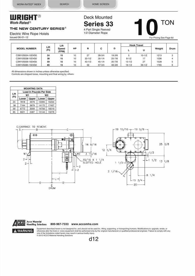
8/21/2019 2013 Wright Specifications Catalog
http://slidepdf.com/reader/full/2013-wright-specifications-catalog 145/189
WORK-RATED® INDEX SEARCH HOME SCREEN
Electric Wire Rope HoistsIssued 06-01-12
Deck Mounted
Series 334 Part Single Reeved1/2 Diameter Rope
MODEL NUMBER
Lift
(Ft)
Lift
Speed
(FPM) HP
B
C
D
Hook Travel
Weight
Drum L U
C3W10S024-15D4S0 24 15 10 27 28-3/4 19-3/8 5 10-1/2 1213 3
C3W10S038-15D4S0 38 15
10
33-1/2
35-1/4
25-7/8
8-1/2
17
1336
4
C3W10S059-15D4S0 59 15
10
43-1/2
45-1/4
35-7/8
13-1/2
27
1528
5
C3W10S085-15D4S0 85 15
10
56
57-3/4
48-3/8
19-1/2
39-1/2
1765
6
MOUNTING DATA
Lift
(Ft)
Load In Pounds Per Side
W1 W2
Lower Upper Lower Upper
24 7818 4979 13395 16234
38 7164 3879 14172 17457
59
6772
3009
14756
18519
85
6621
2487
15144
19278
d12
Equipment described herein is not designed for, and should not be used for, lifting, supporting, or transporting humans. Modifications to upgrade, rerate, orotherwise alter the hoist or crane equipment shall be authorized only by the original manufacturer or qualified professional engineer. Failure to comply with anyone of the limitations noted herein may result in serious bodily injury.© 2012 ACCO Material Handling Solutions
800-967-7333 www.accomhs.com
All dimensions shown in inches unless otherwise specified.Controls are shipped loose, mounting and final wiring by others.
TON 10For Pricing See Page 6d

8/21/2019 2013 Wright Specifications Catalog
http://slidepdf.com/reader/full/2013-wright-specifications-catalog 146/189
WORK-RATED® INDEX SEARCH HOME SCREEN
Electric Wire Rope HoistsIssued 06-01-12
Deck Mounted
Series 344 Part Single Reeved
5/8 Diameter Rope
MODEL NUMBER
Lift
(Ft)
Lift
Speed
(FPM) HP
B
C
D
Hook Travel
Weight
DrumL U
C4W10S025-22D4S0 25 22
15
29
34-7/8
21-7/8
5-15/16
11-5/8
2170
3
C4W10S038-22D4S0 38 22
15
35
40-7/8
27-7/8
8-15/16
17-5/8
2320
4
C4W10S061-22D4S0 61 22 15 46 51-7/8 38-7/8 14-7/16 28-5/8 2630 5
C4W10S092-22D4S0 92 22 15 61 66-7/8 53-7/8 21-15/16 43-5/8 3000 6
MOUNTING DATA
Lift
(Ft)
Load In Pounds Per Side
W1 W2
Lower
Upper
Lower
Upper
25 7867 5267 14303 16903
38
7436
4319
14884
18001
61 7081 3431 15549 19199
92 6895 2870 16105 20130
d13
Equipment described herein is not designed for, and should not be used for, lifting, supporting, or transporting humans. Modifications to upgrade, rerate, orotherwise alter the hoist or crane equipment shall be authorized only by the original manufacturer or qualified professional engineer. Failure to comply with anyone of the limitations noted herein may result in serious bodily injury.© 2012 ACCO Material Handling Solutions
800-967-7333 www.accomhs.com
TON10For Pricing See Page 6d
All dimensions shown in inches unless otherwise specified.Controls are shipped loose, mounting and final wiring by others.
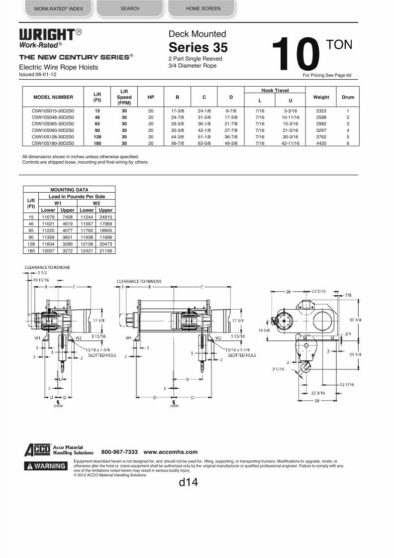
8/21/2019 2013 Wright Specifications Catalog
http://slidepdf.com/reader/full/2013-wright-specifications-catalog 147/189
WORK-RATED® INDEX SEARCH HOME SCREEN
Electric Wire Rope HoistsIssued 06-01-12
Deck Mounted
Series 352 Part Single Reeved
3/4 Diameter Rope
MODEL NUMBER
Lift (Ft)
Lift
Speed (FPM)
HP
B
C
D
Hook Travel
Weight
Drum
L
U
C5W10S015-30D2S0 15 30 20 17-3/8 24-1/8 9-7/8 7/16 3-3/16 2323 1
C5W10S048-30D2S0 46 30 20 24-7/8 31-5/8 17-3/8 7/16 10-11/16 2588 2
C5W10S065-30D2S0 65 30
20
29-3/8
36-1/8
21-7/8
7/16
15-3/16
2982
3
C5W10S090-30D2S0 90 30
20
35-3/8
42-1/8
27-7/8
7/16
21-3/16
3297
4
C5W10S128-30D2S0 128 30 20 44-3/8 51-1/8 36-7/8 7/16 30-3/16 3762 5
C5W10S180-30D2S0 180 30 20 56-7/8 63-5/8 49-3/8 7/16 42-11/16 4420 6
MOUNTING DATA
Lift
(Ft)
Load In Pounds Per Side
W1 W2
Lower Upper Lower Upper
15 11079 7408 11244 24915
46 11021 4619 11567 17969
65
11220
4077
11762
18905
90
11359
3601
11938
11696
128
11604
3289
12158
20473
180 12007 3272 12421 21156
d14
Equipment described herein is not designed for, and should not be used for, lifting, supporting, or transporting humans. Modifications to upgrade, rerate, orotherwise alter the hoist or crane equipment shall be authorized only by the original manufacturer or qualified professional engineer. Failure to comply with anyone of the limitations noted herein may result in serious bodily injury.© 2012 ACCO Material Handling Solutions
800-967-7333 www.accomhs.com
TON 10For Pricing See Page 6d
All dimensions shown in inches unless otherwise specified.Controls are shipped loose, mounting and final wiring by others.
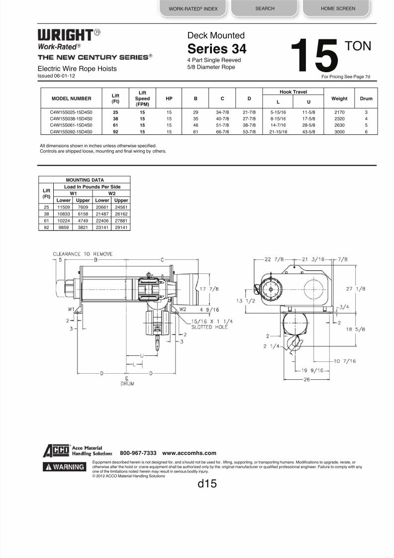
8/21/2019 2013 Wright Specifications Catalog
http://slidepdf.com/reader/full/2013-wright-specifications-catalog 148/189
WORK-RATED® INDEX SEARCH HOME SCREEN
Electric Wire Rope HoistsIssued 06-01-12
Deck Mounted
Series 344 Part Single Reeved
5/8 Diameter Rope
MODEL NUMBER
Lift
(Ft)
Lift
Speed
(FPM) HP
B
C
D
Hook Travel
Weight
DruL U
C4W15S025-15D4S0 25 15 15 29 34-7/8 21-7/8 5-15/16 11-5/8 2170 3
C4W15S038-15D4S0 38 15
15
35
40-7/8
27-7/8
8-15/16
17-5/8
2320
4
C4W15S061-15D4S0 61 15
15
46
51-7/8
38-7/8
14-7/16
28-5/8
2630
5
C4W15S092-15D4S0 92 15 15 61 66-7/8 53-7/8 21-15/16 43-5/8 3000 6
MOUNTING DATA
Lift
(Ft)
Load In Pounds Per Side
W1
W2
Lower Upper Lower Upper
25 11509 7609 20661 24561
38 10833 6158 21487 26162
61 10224 4749 22406 27881
92
9859
3821
23141
29141
d15
Equipment described herein is not designed for, and should not be used for, lifting, supporting, or transporting humans. Modifications to upgrade, rerate, orotherwise alter the hoist or crane equipment shall be authorized only by the original manufacturer or qualified professional engineer. Failure to comply with anyone of the limitations noted herein may result in serious bodily injury.© 2012 ACCO Material Handling Solutions
800-967-7333 www.accomhs.com
TON15For Pricing See Page 7d
All dimensions shown in inches unless otherwise specified.Controls are shipped loose, mounting and final wiring by others.

8/21/2019 2013 Wright Specifications Catalog
http://slidepdf.com/reader/full/2013-wright-specifications-catalog 149/189
WORK-RATED® INDEX SEARCH HOME SCREEN
Electric Wire Rope HoistsIssued 06-01-12
Deck Mounted
Series 354 Part Single Reeved
3/4 Diameter Rope
MODEL NUMBER
Lift (Ft)
Lift
Speed
(FPM) HP
B
C
D
Hook Travel
Weight
Drum L U
C5W15S021-22D4S0 21 22
20
29-3/8
36-1/8
21-7/8
4-13/16
10
2950
3
C5W15S034-22D4S0 34 22
20
35-3/8
42·1/8
27-7/8
7-13/16
16
3248
4
C5W15S053-22D4S0 53 22 20 44-3/8 51-1/8 36-7/8 12-5/16 25 3472 5
C5W15S079-22D4S0 79 22 20 56-7/8 63-5/8 49-3/8 18-9/16 37-1/2 4438 6
MOUNTING DATA
Lift
(Ft)
Load In Pounds Per Side
W1
W2
Lower Upper Lower Upper
21
12705
9148
20245
23802
34
12289
7547
20959
25701
53 11340 6179 22132 27293
79 11316 5563 23122 28875
d16
Equipment described herein is not designed for, and should not be used for, lifting, supporting, or transporting humans. Modifications to upgrade, rerate, orotherwise alter the hoist or crane equipment shall be authorized only by the original manufacturer or qualified professional engineer. Failure to comply with anyone of the limitations noted herein may result in serious bodily injury.© 2012 ACCO Material Handling Solutions
800-967-7333 www.accomhs.com
TON 15For Pricing See Page 7d
All dimensions shown in inches unless otherwise specified.Controls are shipped loose, mounting and final wiring by others.

8/21/2019 2013 Wright Specifications Catalog
http://slidepdf.com/reader/full/2013-wright-specifications-catalog 150/189
WORK-RATED® INDEX SEARCH HOME SCREEN
Electric Wire Rope HoistsIssued 06-01-12
Deck Mounted
Series 354 Part Single Reeved
3/4 Diameter Rope
MODEL NUMBER
Lift
(Ft)
Lift
Speed
(FPM) HP
B
C
D
Hook Travel
Weight
DrumL U
C5W20S021-15D4S0 21 15
20
29-3/8
36-1/8
21-7/8
4-13/16
10
2950
3
C5W20S034-15D4S0 34 15
20
35-3/8
42-1/8
27-7/8
7-13/16
16
3248
4
C5W20S053-15D4S0 53 15 20 44-3/8 51-1/8 36-7/8 12-5/16 25 3472 5
C5W20S079-15D4S0 79 15 20 56-7/8 63-5/8 49-3/8 18-9/16 37-1/2 4438 6
MOUNTING DATA
Lift
(Ft)
Load In Pounds Per Side
W1 W2
Lower Upper Lower Upper
21 16005 11862 26345 31088
34
16000
9677
27248
33571
53
14671
7790
28801
35682
79 14436 6765 30002 37673
d17
Equipment described herein is not designed for, and should not be used for, lifting, supporting, or transporting humans. Modifications to upgrade, rerate, orotherwise alter the hoist or crane equipment shall be authorized only by the original manufacturer or qualified professional engineer. Failure to comply with anyone of the limitations noted herein may result in serious bodily injury.© 2012 ACCO Material Handling Solutions
800-967-7333 www.accomhs.com
TON20For Pricing See Page 8d
All dimensions shown in inches unless otherwise specified.Controls are shipped loose, mounting and final wiring by others.

8/21/2019 2013 Wright Specifications Catalog
http://slidepdf.com/reader/full/2013-wright-specifications-catalog 151/189
WORK-RATED® INDEX SEARCH HOME SCREEN
Deck Mounted
Series 322 Part Double Reeved
3/8 Diameter Rope
MODEL NUMBER
Lift
(Ft)
Lift
Speed (FPM)
HP
B
C
D
E
Weight
Drum
C2W01D020-15D2D0 20 15
3
23-3/8
25-7/8
15-3/4
16-1/2
748
4
C2W01D036-15D2D0 36 15 3 30-7/8 33-3/8 23-1/4 24 839 6
C2W01D060-15D2D0 60 15 3 42-1/2 44-1/2 34-3/8 35-1/8 993 7
C2W01D085-15D2D0 85 15
3
53-3/4
56-1/4
46-1/8
46-7/8
1142
8
C2W01D020-22D2D0 20 22 3 23-3/8 25-7/8 15-3/4 16-1/2 748 4
C2W01D036-22D2D0 36 22
3
30-7/8
33-3/8
23-1/4
24
839
6
C2W01D060-22D2D0 60 22
3
42-1/2
44-1/2
34-3/8
35-1/8
993
7
C2W01D085-22D2D0 85 22 3 53-3/4 56-1/4 46-1/8 46-7/8 1142 8
C2W01D020-30D2D0 20 30 3 23-3/8 25-7/8 15-3/4 16-1/2 748 4
C2W01D036-30D2D0 36 30 3 30-7/8 33-3/8 23-1/4 24 839 6
C2W01D060-30D2D0 60 30
3
42-1/2
44-1/2
34-3/8
35-1/8
993
7
C2W01D085-30D2D0 85 30
3
53-3/4
56-1/4
46-1/8
46-7/8
1142
8
MOUNTING DATA
Lift Load In Pounds Per Side
(Ft) W1 W2
20 1261 1487
36 1291 1548
60
1356
1637
85 1426 1716
d18
Equipment described herein is not designed for, and should not be used for, lifting, supporting, or transporting humans. Modifications to upgrade, rerate, orotherwise alter the hoist or crane equipment shall be authorized only by the original manufacturer or qualified professional engineer. Failure to comply with anyone of the limitations noted herein may result in serious bodily injury.© 2012 ACCO Material Handling Solutions
800-967-7333 www.accomhs.com
TON 1For Pricing See Page 9d
All dimensions shown in inches unless otherwise specified.Controls are shipped loose, mounting and final wiring by others.
Electric Wire Rope HoistsIssued 06-01-12

8/21/2019 2013 Wright Specifications Catalog
http://slidepdf.com/reader/full/2013-wright-specifications-catalog 152/189
WORK-RATED® INDEX SEARCH HOME SCREEN
Electric Wire Rope HoistsIssued 06-01-12
Deck Mounted
Series 332 Part Double Reeved
3/8 Diameter Rope
d19
MODEL NUMBER
Lift
(Ft)
Lift
Speed
(FPM) HP
B
C
D
E
F
Weight
Drum
C3W01D020-44D2D0 20 44 7-1/2 21-1/8 23-5/8 13-1/2 14-1/4 23-3/8 1046 2
C3W01D036-44D2D0 36 44
7-1/2
26-5/8
29-1/8
19
19-3/4
23-3/8
1140
3
C3W01D054-44D2D0 54 44
7-1/2
33-1/8
35-5/8
25-1/2
26-1/4
23-3/8
1249
4
C3W01D082-44D2D0 82 44 7-1/2 43-1/8 45-5/8 35-1/2 36-1/4 23-3/8 1420 5
C3W01D118-44D2D0 118 44 7-1/2 55-5/8 58-1/8 48 48-3/4 25-3/8 1632 6
MOUNTING DATA
Lift (Ft)
Load in Pounds Per Side
W1
W2
20
1468 1578
36 1384 1756
54 1425 1824
82 1498 1922
118
1596 2036
Equipment described herein is not designed for, and should not be used for, lifting, supporting, or transporting humans. Modifications to upgrade, rerate, orotherwise alter the hoist or crane equipment shall be authorized only by the original manufacturer or qualified professional engineer. Failure to comply with anyone of the limitations noted herein may result in serious bodily injury.
© 2012 ACCO Material Handling Solutions
800-967-7333 www.accomhs.com
TON1For Pricing See Page 9d
All dimensions shown in inches unless otherwise specified.Controls are shipped loose, mounting and final wiring by others.

8/21/2019 2013 Wright Specifications Catalog
http://slidepdf.com/reader/full/2013-wright-specifications-catalog 153/189
WORK-RATED® INDEX SEARCH HOME SCREEN
Electric Wire Rope HoistsIssued 06-01-12
Deck Mounted
Series 322 Part Double Reeved
3/8 Diameter Rope
MODEL NUMBER
Lift
(Ft)
Lift
Speed
(FPM) HP
B
C
D
E
Weight
Drum
C2W02D020-15D2D0 20 15
3
23-3/8
25-7/8
15-3/4
16-1/2
748
4
C2W02D036-15D2D0 36 15 3 30-7/8 33-3/8 23-1/4 24 839 6
C2W02D060-15D2D0 60 15 3 42-1/2 44-1/2 34-3/8 35-1/8 993 7
C2W02D085-15D2D0 85 15
3
53-3/4
56-1/4
46-1/8
46-7/8
1142
8
C2W02D020-22D2D0 20 22 3 23-3/8 25-7/8 15-3/4 16-1/2 748 4
C2W02D036-22D2D0 36 22
3
30-7/8
33-3/8
23-1/4
24
839
6
C2W02D060-22D2D0 60 22
3
42-1/2
44-1/2
34-3/8
35-1/8
993
7
C2W02D085-22D2D0 85 22 3 53-3/4 56-1/4 46-1/8 46-7/8 1142 8
C2W02D020-30D2D0 20 30 5 23-3/8 25-7/8 15-3/4 16-1/2 748 4
C2W02D036-30D2D0 36 30 5 30-7/8 33-3/8 23-1/4 24 839 6
C2W02D060-30D2D0 60 30 5 42-1/2 44-1/2 34-3/8 35-1/8 993 7
C2W02D085-30D2D0 85 30
5
53-3/4
56-1/4
46-1/8
46-7/8
1142
8
MOUNTING DATA
Lift Load In Pounds Per Side
(Ft) W1 W2
20
2285
2463
36 2307 2532
60 2367 2626
85 2434 2708
d20
Equipment described herein is not designed for, and should not be used for, lifting, supporting, or transporting humans. Modifications to upgrade, rerate, orotherwise alter the hoist or crane equipment shall be authorized only by the original manufacturer or qualified professional engineer. Failure to comply with anyone of the limitations noted herein may result in serious bodily injury.© 2012 ACCO Material Handling Solutions
800-967-7333 www.accomhs.com
TON 2For Pricing See Page 10d
All dimensions shown in inches unless otherwise specified.Controls are shipped loose, mounting and final wiring by others.

8/21/2019 2013 Wright Specifications Catalog
http://slidepdf.com/reader/full/2013-wright-specifications-catalog 154/189
WORK-RATED® INDEX SEARCH HOME SCREEN
Electric Wire Rope HoistsIssued 06-01-12
Deck Mounted
Series 332 Part Double Reeved
3/8 Diameter Rope
d21
MODEL NUMBER
Lift
(Ft)
Lift
Speed
(FPM) HP
B
C
D
E
F
Weight
Drum
C3W02D020-44D2D0 20 44 7-1/2 21-1/8 23-5/8 13-1/2 14-1/4 23-3/8 1046 2
C3W02D036-44D2D0 36 44
7-1/2
26-5/8
29-1/8
19
19-3/4
23-3/8
1140
3
C3W02D054-44D2D0 54 44
7-1/2
33-1/8
35-5/8
25-1/2
26-1/4
23-3/8
1249
4
C3W02D082-44D2D0 82 44 7-1/2 43-1/8 45-5/8 35-1/2 36-1/4 23-3/8 1420 5
C3W02D118-44D2D0 118 44 7-1/2 55-5/8 58-1/8 48 48-3/4 25-3/8 1632 6
MOUNTING DATA
Lift (Ft)
Load in Pounds Per Side
W1
W2
20
2495 2551
36 2403 2737
54 2440 2809
82
2508 2912
118
2604 3028
Equipment described herein is not designed for, and should not be used for, lifting, supporting, or transporting humans. Modifications to upgrade, rerate, orotherwise alter the hoist or crane equipment shall be authorized only by the original manufacturer or qualified professional engineer. Failure to comply with anyone of the limitations noted herein may result in serious bodily injury.© 2012 ACCO Material Handling Solutions
800-967-7333 www.accomhs.com
TON2For Pricing See Page 1
All dimensions shown in inches unless otherwise specified.Controls are shipped loose, mounting and final wiring by others.

8/21/2019 2013 Wright Specifications Catalog
http://slidepdf.com/reader/full/2013-wright-specifications-catalog 155/189
WORK-RATED® INDEX SEARCH HOME SCREEN
Electric Wire Rope HoistsIssued 06-01-12
Deck Mounted
Series 322 Part Double Reeved
3/8 Diameter Rope
MODEL NUMBER
Lift
(Ft)
Lift
Speed (FPM)
HP
B
C
D
E
Weight
Drum
C2W03D020-15D2D0 20 15
3
23-3/8
25-7/8
15-3/4
16-1/2
748
4
C2W03D036-15D2D0 36 15 3 30-7/8 33-3/8 23-1/4 24 839 6
C2W03D060-15D2D0 60 15
3
42-1/2
44-1/2
34-3/8
35-1/8
993
7
C2W03D085-15D2D0 85 15
3
53-3/4
56-1/4
46-1/8
46-7/8
1142
8
C2W03D020-22D2D0 20 22
5
23-3/8
25-7/8
15-3/4
16-1/2
748
4
C2W03D036-22D2D0 36 22
5
30-7/8
33-3/8
23-1/4
24
839
6
C2W03D060-22D2D0 60 22 5 42-1/2 44-1/2 34-3/8 35-1/8 993 7
C2W03D085-22D2D0 85 22
5
53-3/4
56-1/4
46-1/8
46-7/8
1142
8
MOUNTING DATA
Lift Load In Pounds Per Side
(Ft) W1 W2
20 3308 3440
36
3323
3516
60
3378
3615
85
3442
3700
d22
Equipment described herein is not designed for, and should not be used for, lifting, supporting, or transporting humans. Modifications to upgrade, rerate, orotherwise alter the hoist or crane equipment shall be authorized only by the original manufacturer or qualified professional engineer. Failure to comply with anyone of the limitations noted herein may result in serious bodily injury.
© 2012 ACCO Material Handling Solutions
800-967-7333 www.accomhs.com
TON 3For Pricing See Page 11d
All dimensions shown in inches unless otherwise specified.Controls are shipped loose, mounting and final wiring by others.

8/21/2019 2013 Wright Specifications Catalog
http://slidepdf.com/reader/full/2013-wright-specifications-catalog 156/189
WORK-RATED® INDEX SEARCH HOME SCREEN
Electric Wire Rope HoistsIssued 06-01-12
Deck Mounted
Series 332 Part Double Reeved
3/8 Diameter Rope
MODEL NUMBER
Lift (Ft)
Lift
Speed (FPM)
HP
B
C
D
E
F
Weight
Drum
C3W03D020-30D2D0 20 30 7-1/2 21-1/8 23-5/8 13-1/2 14-1/4 23-3/8 1046 2
C3W03D036-30D2D0 36 30
7-1/2
26-5/8
29-1/8
19
19-3/4
23-3/8
1140
3
C3W03D054-30D2D0 54 30
7-1/2
33-1/8
35-5/8
25-1/2
26-1/4
23-3/8
1249
4
C3W03D082-30D2D0 82 30 7-1/2 43-1/8 45-5/8 35-1/2 36-1/4 23-3/8 1420 5
C3W03D118-30D2D0 118 30 7-1/2 55-5/8 58-1/8 48 48-3/4 25-3/8 1632 6
C3W03D020-44D2D0 20 44 10 21-1/8 23-5/8 13-1/2 14-1/4 23-3/8 1046 2
C3W03D036-44D2D0 36 44 10 26-5/8 29-1/8 19 19-3/4 23-3/8 1140 3
C3W03D054-44D2D0 54 44
10
33-1/8
35-5/8
25-1/2
26-1/4
23-3/8
1249
4
C3W03D082-44D2D0 82 44
10
43-1/8
45-5/8
35-1/2
36-1/4
23-3/8
1420
5
C3W03D118-44D2D0 118 44 10 55-5/8 58-1/8 48 48-3/4 25-3/8 1632 6
MOUNTING DATA
Lift
(Ft)
Load in Pounds Per side
W1 W2
20
3522 3524
36 3423 3717
54
3454 3795
82
3519 3901
118
3612 4020
d23
Equipment described herein is not designed for, and should not be used for, lifting, supporting, or transporting humans. Modifications to upgrade, rerate, orotherwise alter the hoist or crane equipment shall be authorized only by the original manufacturer or qualified professional engineer. Failure to comply with anyone of the limitations noted herein may result in serious bodily injury.© 2012 ACCO Material Handling Solutions
800-967-7333 www.accomhs.com
TON3For Pricing See Page 11d
All dimensions shown in inches unless otherwise specified.Controls are shipped loose, mounting and final wiring by others.

8/21/2019 2013 Wright Specifications Catalog
http://slidepdf.com/reader/full/2013-wright-specifications-catalog 157/189
WORK-RATED® INDEX SEARCH HOME SCREEN
Electric Wire Rope HoistsIssued 06-01-12
Deck Mounted
Series 322 Part Double Reeved
3/8 Diameter Rope
MODEL NUMBER
Lift (Ft)
Lift
Speed
(FPM) HP
B
C
D
E
Weight
Drum
C2W05D020-15D2D0 20 15
5
23-3/8
25-7/8
15-3/4
16-1/2
748
4
C2W05D036-15D2D0 36 15
5
30-7/8
33-3/8
23-1/4
24
839
6
C2W05D060-15D2D0 60 15 5 42-1/2 44-1/2 34-3/8 35-1/8 993 7
C2W05D085-15D2D0 85 15 5 53-3/4 56·1/4 46-1/8 46-7/8 1142 8
MOUNTING DATA
Lift (Ft)
Load In Pounds Per Side
W1 W2
20
5354
5394
36 5355 5494
60 5399 5594
85
5459
5683
d24
Equipment described herein is not designed for, and should not be used for, lifting, supporting, or transporting humans. Modifications to upgrade, rerate, orotherwise alter the hoist or crane equipment shall be authorized only by the original manufacturer or qualified professional engineer. Failure to comply with anyone of the limitations noted herein may result in serious bodily injury.
© 2012 ACCO Material Handling Solutions
800-967-7333 www.accomhs.com
TON 5For Pricing See Page 12d
All dimensions shown in inches unless otherwise specified.Controls are shipped loose, mounting and final wiring by others.

8/21/2019 2013 Wright Specifications Catalog
http://slidepdf.com/reader/full/2013-wright-specifications-catalog 158/189
WORK-RATED® INDEX SEARCH HOME SCREEN
Electric Wire Rope HoistsIssued 06-01-12
Deck Mounted
Series 332 Part Double Reeved
3/8 Diameter Rope
MODEL NUMBER
Lift
(Ft)
Lift
Speed
(FPM) HP
B
C
D
E
F
Weight
Drum
C3W05D020-22D2D0 20 22 7-1/2 21-1/8 23-5/8 13-1/2 14-1/4 23-3/8 1046 2
C3W05D036-22D2D0 36 22 7-1/2 26-5/8 29-1/8 19 19-3/4 23-3/8 1140 3
C3W05D054-22D2D0 54 22
7-1/2
33-1/8
35-5/8
25-1/2
26-1/4
23-3/8
1249
4
C3W05D082-22D2D0 82 22 7-1/2 43-1/8 45-5/8 35-1/2 36-1/4 23-3/8 1420 5
C3W05D118-22D2D0 118 22 7-1/2 55-5/8 58-1/8 48 48-3/4 25-3/8 1632 6
C3W05D020-30D2D0 20 30
10
21-1/8
23-5/8
13-1/2
14-1/4
23-3/8
1046
2
C3W05D036-30D2D0 36 30 10 26-5/8 29-1/8 19 19-3/4 23-3/8 1140 3
C3W05D054-30D2D0 54 30 10 33-1/8 35-5/8 25-1/2 26-1/4 23-3/8 1249 4
C3W05D082-30D2D0 82 30
10
43-1/8
45-5/8
35-1/2
36-1/4
23-3/8
1420
5
C3W05D118-30D2D0 118 30 10 55-5/8 58-1/8 48 48-3/4 25-3/8 1632 6
MOUNTING DATA
Lift
(Ft)
Load in Pounds Per Side
W1 W2
20
5576
5470
36 5461 5679
54 5483 5766
82 5540 5880
118
5627
6005
d25
Equipment described herein is not designed for, and should not be used for, lifting, supporting, or transporting humans. Modifications to upgrade, rerate, orotherwise alter the hoist or crane equipment shall be authorized only by the original manufacturer or qualified professional engineer. Failure to comply with anyone of the limitations noted herein may result in serious bodily injury.© 2012 ACCO Material Handling Solutions
800-967-7333 www.accomhs.com
TON5For Pricing See Page 12d
All dimensions shown in inches unless otherwise specified.Controls are shipped loose, mounting and final wiring by others.

8/21/2019 2013 Wright Specifications Catalog
http://slidepdf.com/reader/full/2013-wright-specifications-catalog 159/189
WORK-RATED® INDEX SEARCH HOME SCREEN
Electric Wire Rope HoistsIssued 06-01-12
Deck Mounted
Series 342 Part Double Reeved
1/2 Diameter Rope
MODEL NUMBER
Lift (Ft)
Lift
Speed
(FPM) HP
B
C
D
E
Weight
Drum
C4W05D020-44D2D0 20 44 15 24-1/8 30-3/4 17 17-3/4 2020 2
C4W05D031-44D2D0 31 44
15
28-5/8
35-1/4
21-1/2
22-1/4
2140
3
C4W05D047-44D2D0 47 44
15
34-5/8
41-1/4
27-1/2
28-1/4
2300
4
C4W05D076-44D2D0 76 44 15 45-5/8 52-1/4 38-1/2 39-1/4 2590 5
C4W05D115-44D2D0 115 44 15 60-5/8 67-1/4 53-1/2 54-1/4 2980 6
MOUNTING DATA
Lift (Ft)
Load In Pounds Per Side
W1 W2
20
5676
6344
31 5702 6438
47
5760
6540
76 5873 6717
115 6052 6928
d26
Equipment described herein is not designed for, and should not be used for, lifting, supporting, or transporting humans. Modifications to upgrade, rerate, orotherwise alter the hoist or crane equipment shall be authorized only by the original manufacturer or qualified professional engineer. Failure to comply with anyone of the limitations noted herein may result in serious bodily injury.© 2012 ACCO Material Handling Solutions
800-967-7333 www.accomhs.com
TON 5For Pricing See Page 12d
All dimensions shown in inches unless otherwise specified.Controls are shipped loose, mounting and final wiring by others.

8/21/2019 2013 Wright Specifications Catalog
http://slidepdf.com/reader/full/2013-wright-specifications-catalog 160/189
WORK-RATED® INDEX SEARCH HOME SCREEN
Electric Wire Rope HoistsIssued 06-01-12
Deck Mounted
Series 334 Part Double Reeved
3/8 Diameter Rope
MODEL NUMBER
Lift
(Ft)
Lift
Speed
(FPM) HP
B
C
D
E
F
Weight
Drum
C3W07D022-15D4D0 22 15 7-1/2 33-1/8 35-5/8 25-1/2 26-1/4 25-3/8 1345 4
C3W07D036-15D4D0 36 15 7-1/2 43-1/8 45-5/8 35-1/2 36-1/4 27-5/8 1525 5
C3W07D054-15D4D0 54 15
7-1/2
55-5/8
58-1/8
48
48-3/4
27-5/8
1748
6
C3W07D022-22D4D0 22 22 10 33-1/8 35-5/8 25-1/2 26-1/4 25-3/8 1345 4
C3W07D036-22D4D0 36 22
10
43-1/8
45-5/8
35-1/2
36-1/4
27-5/8
1525
5
C3W07D054-22D4D0 54 22
10
55-5/8
58-1/8
48
48-3/4
27-5/8
1748
6
MOUNTING DATA
Lift
(Ft)
Load in Pounds Per Side
W1
W2
22 8067 8278
36 8118 8407
54
8202
8546
d27
Equipment described herein is not designed for, and should not be used for, lifting, supporting, or transporting humans. Modifications to upgrade, rerate, orotherwise alter the hoist or crane equipment shall be authorized only by the original manufacturer or qualified professional engineer. Failure to comply with anyone of the limitations noted herein may result in serious bodily injury.© 2012 ACCO Material Handling Solutions
800-967-7333 www.accomhs.com
For Pricing See Page 13
TON71
2
All dimensions shown in inches unless otherwise specified.Controls are shipped loose, mounting and final wiring by others.

8/21/2019 2013 Wright Specifications Catalog
http://slidepdf.com/reader/full/2013-wright-specifications-catalog 161/189
WORK-RATED® INDEX SEARCH HOME SCREEN
Electric Wire Rope HoistsIssued 06-01-12
Deck Mounted
Series 342 Part Double Reeved
1/2 Diameter Rope
MODEL NUMBER
Lift
(Ft)
Lift
Speed
(FPM) HP
B
C
D
E
Weight
Drum
C4W07D020-30D2D0 20 30
15
24-1/8
30-3/4
17
17-3/4
2020
2
C4W07D031-30D2D0 31 30 15 28-5/8 35-1/4 21-1/2 22-1/4 2140 3
C4W07D047-30D2D0 47 30 15 34-5/8 41-1/4 27-1/2 28-1/4 2300 4
C4W07D076-30D2D0 76 30
15
45-5/8
52-1/4
38-1/2
39-1/4
2590
5
C4W07D115-30D2D0 115 30
15
60-5/8
67-1/4
53-1/2
54-1/4
2980
6
MOUNTING DATA
Lift (Ft)
Load In Pounds Per Side
W1 W2
20
8230
8790
31
8245
8895
47 8294 9006
76
8397
9193
115
8569
9411
d28
Equipment described herein is not designed for, and should not be used for, lifting, supporting, or transporting humans. Modifications to upgrade, rerate, orotherwise alter the hoist or crane equipment shall be authorized only by the original manufacturer or qualified professional engineer. Failure to comply with anyone of the limitations noted herein may result in serious bodily injury.© 2012 ACCO Material Handling Solutions
800-967-7333 www.accomhs.com
For Pricing See Page 13d
TON 71
2
All dimensions shown in inches unless otherwise specified.Controls are shipped loose, mounting and final wiring by others.

8/21/2019 2013 Wright Specifications Catalog
http://slidepdf.com/reader/full/2013-wright-specifications-catalog 162/189
WORK-RATED® INDEX SEARCH HOME SCREEN
Electric Wire Rope HoistsIssued 06-01-12
Deck Mounted
Series 352 Part Double Reeved
1/2 Diameter Rope
MODEL NUMBER
Lift
(Ft)
Lift
Speed
(FPM) HP
B
C
D
E
Weight
Drum
C5W07D024-44D2D0 24 44 20 24-1/2 32 17 17-3/4 2578 2
C5W07D038-44D2D0 38 44 20 29 36-7/16 21-1/2 22-1/4 2882 3
C5W07D057-44D2D0 57 44
20
35
42-7/16
27-1/2
28-1/4
3156
4
C5W07D085-44D2D0 85 44
20
44
51-7/16
36-1/2
37-1/4
3592
5
C5W07D124-44D2D0 124 44
20
56-1/2
64
49
49-3/4
4248
6
MOUNTING DATA
Lift (Ft)
Load in Pounds Per Side
W1 W2
24 8486 9092
38 8646 9236
57
8783
9373
85 9030 9562
124 9423 9825
d29
Equipment described herein is not designed for, and should not be used for, lifting, supporting, or transporting humans. Modifications to upgrade, rerate, orotherwise alter the hoist or crane equipment shall be authorized only by the original manufacturer or qualified professional engineer. Failure to comply with anyone of the limitations noted herein may result in serious bodily injury.© 2012 ACCO Material Handling Solutions
800-967-7333 www.accomhs.com
For Pricing See Page 13
TON71
2
All dimensions shown in inches unless otherwise specified.Controls are shipped loose, mounting and final wiring by others.

8/21/2019 2013 Wright Specifications Catalog
http://slidepdf.com/reader/full/2013-wright-specifications-catalog 163/189
WORK-RATED® INDEX SEARCH HOME SCREEN
Electric Wire Rope HoistsIssued 06-01-12
Deck Mounted
Series 334 Part Double Reeved
3/8 Diameter Rope
MODEL NUMBER
Lift
(Ft)
Lift
Speed
(FPM) HP
B
C
D
E
F
Weight
Drum
C3W10D022-15D4D0 22 15 10 33-1/8 35-5/8 25-1/2 26-1/4 25-3/8 1345 4
C3W10D036-15D4D0 36 15
10
43-1/8
45-5/8
35-1/2
36-1/4
27-5/8
1525
5
C3W10D054-15D4D0 54 15
10
55-5/8
58-1/8
48
48-3/4
27-5/8
1748
6
MOUNTING DATA
Lift Load In Pounds Per Side
(Ft) W1 W2
22 10603 10742
36 10644 10881
54 10721 11027
d30
Equipment described herein is not designed for, and should not be used for, lift ing, supporting, or transporting humans. Modifications to upgrade, rerate, orotherwise alter the hoist or crane equipment shall be authorized only by the original manufacturer or qualified professional engineer. Failure to comply with anyone of the limitations noted herein may result in serious bodily injury.© 2012 ACCO Material Handling Solutions
800-967-7333 www.accomhs.com
TON 10For Pricing See Page 14d
All dimensions shown in inches unless otherwise specified.Controls are shipped loose, mounting and final wiring by others.

8/21/2019 2013 Wright Specifications Catalog
http://slidepdf.com/reader/full/2013-wright-specifications-catalog 164/189
WORK-RATED® INDEX SEARCH HOME SCREEN
Electric Wire Rope HoistsIssued 06-01-12
Deck Mounted
Series 344 Part Double Reeved
1/2 Diameter Rope
MOUNTING DATA
Lift Load In Pounds Per Side
(Ft) W1 W2
20
10957
11603
35
11070
11810
54
11288
12092
d31
Equipment described herein is not designed for, and should not be used for, lifting, supporting, or transporting humans. Modifications to upgrade, rerate, orotherwise alter the hoist or crane equipment shall be authorized only by the original manufacturer or qualified professional engineer. Failure to comply with any
one of the limitations noted herein may result in serious bodily injury.© 2012 ACCO Material Handling Solutions
800-967-7333 www.accomhs.com
MODEL NUMBER
Lift
(Ft) Lift
Speed
(FPM)
HP B C D E F Weight Drum
C4W10D020-22D4D0 20 22 15 34-5/8 41-1/4 27-1/2 28-1/4 27-1/8 2560 4
C4W10D035-22D4D0 35 22
15
45-5/8
52-1/4
38-1/2
39-1/4
27-1/8 2880
5
C4W10D054-22D4D0 54 22 15 60-5/8 67-1/4 53-1/2 54-1/4 29-1/8 3380 6
TON10For Pricing See Page 14d
All dimensions shown in inches unless otherwise specified.Controls are shipped loose, mounting and final wiring by others.

8/21/2019 2013 Wright Specifications Catalog
http://slidepdf.com/reader/full/2013-wright-specifications-catalog 165/189
WORK-RATED® INDEX SEARCH HOME SCREEN
Electric Wire Rope HoistsIssued 06-01-12
Deck Mounted
Series 352 Part Double Reeved
1/2 Diameter Rope
MOUNTING DATA
Lift Load In Pounds Per Side
(Ft)
W1
W2
24
11040
11538
38 11189 11693
57 11317 11839
85 11555 12037
124
11942
12306
MODEL NUMBER
Lift (Ft)
Lift
Speed
(FPM) HP
B
C
D
E
Weight
Drum
C5W10D024-30D2D0 24 30 20 24-1/2 32 17 17-3/4 2578 2
C5W10D038-30D2D0 38 30
20
29
36-7/16
21-1/2
22-1/4
2882
3
C5W10D057-30D2D0 57 30
20
35
42-7/16
27-1/2
28-1/4
3156
4
C5W10D085-30D2D0 85 30 20 44 51-7/16 36-1/2 37-1/4 3592 5
C5W10D124-30D2D0 124 30 20 56-1/2 64 49 49-3/4 4248 6
d32
Equipment described herein is not designed for, and should not be used for, lifting, supporting, or transporting humans. Modifications to upgrade, rerate, orotherwise alter the hoist or crane equipment shall be authorized only by the original manufacturer or qualified professional engineer. Failure to comply with anyone of the limitations noted herein may result in serious bodily injury.© 2012 ACCO Material Handling Solutions
800-967-7333 www.accomhs.com
TON 10For Pricing See Page 14d
All dimensions shown in inches unless otherwise specified.Controls are shipped loose, mounting and final wiring by others.

8/21/2019 2013 Wright Specifications Catalog
http://slidepdf.com/reader/full/2013-wright-specifications-catalog 166/189
WORK-RATED® INDEX SEARCH HOME SCREEN
Electric Wire Rope HoistsIssued 06-01-12
Deck Mounted
Series 344 Part Double Reeved
1/2 Diameter Rope
MOUNTING DATA
Lift Load In Pounds Per Side
(Ft) W1 W2
20
15997
16553
35 16120 16800
54 16352 17118
MODEL NUMBER
Lift
(Ft)
Lift
Speed
(FPM) HP
B
C
D
E
F
Weight
Drum
C4W15D020-15D4D0 20 15 15 34-5/8 41-1/4 27-1/2 28-1/4 27-1/8 2550 4
C4W15D035-15D4D0 35 15 15 45-5/8 52-1/4 38-1/2 39-1/4 27-1/8 2870 5
C4W15D054-15D4D0 54 15
15
60-5/8
67-1/4
53-1/2
54-1/4
29-1/8 3370
6
d33
Equipment described herein is not designed for, and should not be used for, lifting, supporting, or transporting humans. Modifications to upgrade, rerate, orotherwise alter the hoist or crane equipment shall be authorized only by the original manufacturer or qualified professional engineer. Failure to comply with any
one of the limitations noted herein may result in serious bodily injury.© 2012 ACCO Material Handling Solutions
800-967-7333 www.accomhs.com
TON15For Pricing See Page 15d
All dimensions shown in inches unless otherwise specified.Controls are shipped loose, mounting and final wiring by others.

8/21/2019 2013 Wright Specifications Catalog
http://slidepdf.com/reader/full/2013-wright-specifications-catalog 167/189
WORK-RATED® INDEX SEARCH HOME SCREEN
Electric Wire Rope HoistsIssued 06-01-12
Deck Mounted
Series 354 Part Double Reeved
1/2 Diameter Rope
MODEL NUMBER
Lift (Ft)
Lift
Speed
(FPM) HP
B
C
D
E
F
Weight
Drum
C5W15D024-22D4D0 24 22
20
34-7/8
42-7/16
27-1/2
28-1/4
30-1/4
3155
4
C5W15D039-22D4D0 39 22
20
43-7/8
51-7/16
36-1/2
37-1/4
30-1/2
3530
5
C5W15D058-22D4D0 58 22 20 56-3/8 64 49 49-3/4 32-1/2 4060 6
MOUNTING DATA
Lift Load In Pounds Per Side
(Ft) W1 W2
24 16242 16914
39
16337
17137
58
16547
17414
d34
Equipment described herein is not designed for, and should not be used for, lifting, supporting, or transporting humans. Modifications to upgrade, rerate, orotherwise alter the hoist or crane equipment shall be authorized only by the original manufacturer or qualified professional engineer. Failure to comply with anyone of the limitations noted herein may result in serious bodily injury.© 2012 ACCO Material Handling Solutions
800-967-7333 www.accomhs.com
TON 15For Pricing See Page 15d
All dimensions shown in inches unless otherwise specified.Controls are shipped loose, mounting and final wiring by others.

8/21/2019 2013 Wright Specifications Catalog
http://slidepdf.com/reader/full/2013-wright-specifications-catalog 168/189
WORK-RATED® INDEX SEARCH HOME SCREEN
Electric Wire Rope HoistsIssued 06-01-12
Deck Mounted
Series 354 Part Double Reeved
1/2 Diameter Rope
MODEL NUMBER
Lift
(Ft)
Lift
Speed
(FPM) HP
B
C
D
E
F
Weight
Drum
C5W20D024-15D4D0 24 15 20 34-7/8 42-7/16 27-1/2 28-1/4 30-1/4 3155 4
C5W20D039-15D4D0 39 15 20 43-7/8 51-7/16 36-1/2 37-1/4 30-1/2 3530 5
C5W20D058-15D4D0 58 15
20
56-3/8
64
49
49-3/4
32-1/2
4060
6
MOUNTING DATA
Lift Load In Pounds Per Side
(Ft) W1 W2
24
21312
21844
39
21387
22087
58 21587 22374
d35
Equipment described herein is not designed for, and should not be used for, lifting, supporting, or transporting humans. Modifications to upgrade, rerate, orotherwise alter the hoist or crane equipment shall be authorized only by the original manufacturer or qualified professional engineer. Failure to comply with anyone of the limitations noted herein may result in serious bodily injury.© 2012 ACCO Material Handling Solutions
800-967-7333 www.accomhs.com
TON20For Pricing See Page 16
All dimensions shown in inches unless otherwise specified.Controls are shipped loose, mounting and final wiring by others.

8/21/2019 2013 Wright Specifications Catalog
http://slidepdf.com/reader/full/2013-wright-specifications-catalog 169/189
WORK-RATED® INDEX SEARCH HOME SCREEN
Electric Wire Rope HoistsIssued 06-01-12
Deck Mounted
Series 354 Part Double Reeved
9/16 Diameter Rope
MODEL NUMBER
Lift (Ft)
Lift
Speed
(FPM) HP
B
C
D
E
F
Weight
Drum
C5W25D020-12D4D0 20 12
20
34-1/8
43-9/16
26-5/8
29-1/8
30-1/4
3809
4
C5W25D032-12D4D0 32 12
20
43-1/8
52-9/16
35-5/8
38-1/8
30-1/4
4165
5
C5W25D048-12D4D0 48 12 20 55-11/16 65-1/16 48-1/8 50-5/8 30-1/4 4660 6
MOUNTING DATA
Lift Load In Pounds Per Side
(Ft) W1 W2
20
27613
26196
32
27588
26577
48 27677 26983
d36
Equipment described herein is not designed for, and should not be used for, lifting, supporting, or transporting humans. Modifications to upgrade, rerate, orotherwise alter the hoist or crane equipment shall be authorized only by the original manufacturer or qualified professional engineer. Failure to comply with anyone of the limitations noted herein may result in serious bodily injury.
© 2012 ACCO Material Handling Solutions
800-967-7333 www.accomhs.com
TON 25For Pricing See Page 17d
All dimensions shown in inches unless otherwise specified.Controls are shipped loose, mounting and final wiring by others.
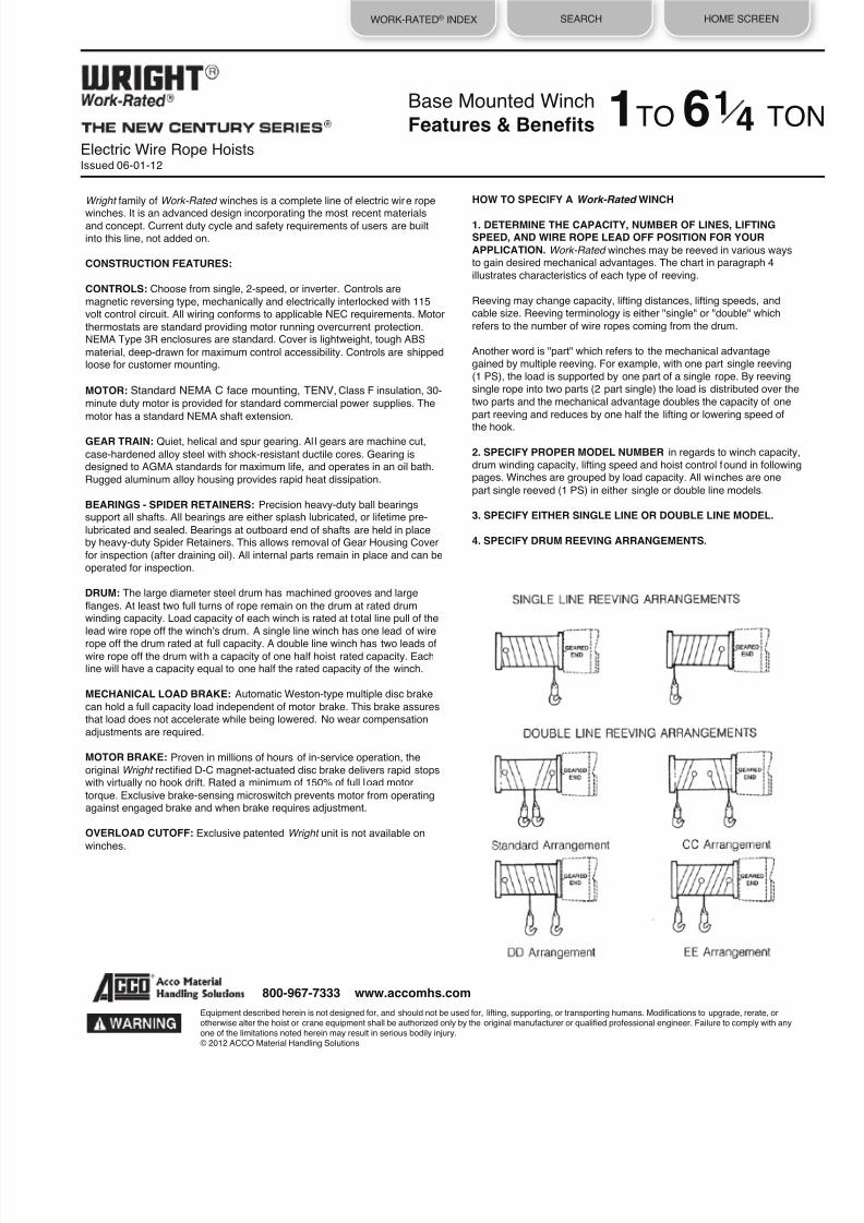
8/21/2019 2013 Wright Specifications Catalog
http://slidepdf.com/reader/full/2013-wright-specifications-catalog 170/189
WORK-RATED® INDEX SEARCH HOME SCREEN
Equipment described herein is not designed for, and should not be used for, lifting, supporting, or transporting humans. Modifications to upgrade, rerate, orotherwise alter the hoist or crane equipment shall be authorized only by the original manufacturer or qualified professional engineer. Failure to comply with anyone of the limitations noted herein may result in serious bodily injury.© 2012 ACCO Material Handling Solutions
800-967-7333 www.accomhs.com
Electric Wire Rope HoistsIssued 06-01-12
Wright family of Work-Rated winches is a complete line of electric wire rope
winches. It is an advanced design incorporating the most recent materialsand concept. Current duty cycle and safety requirements of users are builtinto this line, not added on.
CONSTRUCTION FEATURES:
CONTROLS: Choose from single, 2-speed, or inverter. Controls are
magnetic reversing type, mechanically and electrically interlocked with 115volt control circuit. All wiring conforms to applicable NEC requirements. Motor
thermostats are standard providing motor running overcurrent protection.NEMA Type 3R enclosures are standard. Cover is lightweight, tough ABS
material, deep-drawn for maximum control accessibility. Controls are shippedloose for customer mounting.
MOTOR: Standard NEMA C face mounting, TENV, Class F insulation, 30-
minute duty motor is provided for standard commercial power supplies. The
motor has a standard NEMA shaft extension.
GEAR TRAIN: Quiet, helical and spur gearing. Al l gears are machine cut,
case-hardened alloy steel with shock-resistant ductile cores. Gearing isdesigned to AGMA standards for maximum life, and operates in an oil bath.
Rugged aluminum alloy housing provides rapid heat dissipation.
BEARINGS - SPIDER RETAINERS: Precision heavy-duty ball bearingssupport all shafts. All bearings are either splash lubricated, or lifetime pre-
lubricated and sealed. Bearings at outboard end of shafts are held in placeby heavy-duty Spider Retainers. This allows removal of Gear Housing Cover
for inspection (after draining oil). All internal parts remain in place and can beoperated for inspection.
DRUM: The large diameter steel drum has machined grooves and large
flanges. At least two full turns of rope remain on the drum at rated drumwinding capacity. Load capacity of each winch is rated at total line pull of the
lead wire rope off the winch's drum. A single line winch has one lead of wire
rope off the drum rated at full capacity. A double line winch has two leads ofwire rope off the drum with a capacity of one half hoist rated capacity. Eachline will have a capacity equal to one half the rated capacity of the winch.
MECHANICAL LOAD BRAKE: Automatic Weston-type multiple disc brake
can hold a full capacity load independent of motor brake. This brake assuresthat load does not accelerate while being lowered. No wear compensation
adjustments are required.
MOTOR BRAKE: Proven in millions of hours of in-service operation, the
original Wright rectified D-C magnet-actuated disc brake delivers rapid stopswith virtually no hook drift. Rated a minimum of 150% of full load motor
torque. Exclusive brake-sensing microswitch prevents motor from operatingagainst engaged brake and when brake requires adjustment.
OVERLOAD CUTOFF: Exclusive patented Wright unit is not available on
winches.
HOW TO SPECIFY A Work-Rated WINCH
1. DETERMINE THE CAPACITY, NUMBER OF LINES, LIFTING
SPEED, AND WIRE ROPE LEAD OFF POSITION FOR YOUR
APPLICATION. Work-Rated winches may be reeved in various waysto gain desired mechanical advantages. The chart in paragraph 4
illustrates characteristics of each type of reeving.
Reeving may change capacity, lifting distances, lifting speeds, andcable size. Reeving terminology is either "single" or "double" which
refers to the number of wire ropes coming from the drum.
Another word is "part" which refers to the mechanical advantagegained by multiple reeving. For example, with one part single reeving
(1 PS), the load is supported by one part of a single rope. By reevingsingle rope into two parts (2 part single) the load is distributed over the
two parts and the mechanical advantage doubles the capacity of one
part reeving and reduces by one half the lifting or lowering speed of
the hook.
2. SPECIFY PROPER MODEL NUMBER in regards to winch capacity,
drum winding capacity, lifting speed and hoist control found in followingpages. Winches are grouped by load capacity. All winches are one
part single reeved (1 PS) in either single or double line models.
3. SPECIFY EITHER SINGLE LINE OR DOUBLE LINE MODEL.
4. SPECIFY DRUM REEVING ARRANGEMENTS.
Base Mounted Winch
Features & Benefits 1TO 6 TO1
4

8/21/2019 2013 Wright Specifications Catalog
http://slidepdf.com/reader/full/2013-wright-specifications-catalog 171/189
WORK-RATED® INDEX SEARCH HOME SCREEN
Equipment described herein is not designed for, and should not be used for, lifting, supporting, or transporting humans. Modifications to upgrade, rerate, orotherwise alter the hoist or crane equipment shall be authorized only by the original manufacturer or qualified professional engineer. Failure to comply with anyone of the limitations noted herein may result in serious bodily injury.© 2012 ACCO Material Handling Solutions
800-967-7333 www.accomhs.com
Electric Wire Rope HoistsIssued 06-01-12
5. DETERMINE IF STANDARD LINE LEADOFF ANGLE IS
APPROPRIATE. Work-Rated winches are designed with a standard range orranges of leadoff angles. See the illustration below for location of the
standard range.
If any of desired leadoff angle falls into non standard area, the factory mustbe consulted for fabrication and additional pr icing factors. Specify the desired
angle range viewed from the gearing end of winch. State angle in EXACTdegree clockwise from zero vertical leadoff position as shown. If a range of
degrees is required, state both limits in degrees.
7. SPECIFY CABLE FITTINGS. The drum end (live end) cable fit ting is
attached to wire rope when supplied from the factory. The cable fittingis designed for easy installation and is swaged on to provide maximumsecurity. See Accessories Section for pricing.
The following "DEAD END" cable fittings are available on application:
• Eye Bolt • Turn Buckle • Threaded Rod • Swivel Hook
The "DEAD END" of wire rope may be specified "OPEN" (no fittings) orwith any of the above fittings.
8. SPECIFY LOAD BLOCK AND IDLER SHEAVES. Information and
data for these items are found in Accessories Section.
9. SPECIFY MOTOR VOLTAGE. Wright standard motors are available
in 200/230/460/575-3-60 power with Class F insulation, and are totallyenclosed non-ventilated.
10. CONTROL. Control is furnished as standard equipment. Additionalmotor and control accessories and modifications are found inAccessories Section. Control is shipped loose for customer mounting.
If control mounting by ACCO is desired, contact factory for pricing.Contact factory for control dimensions and locations.
11. SPECIFY PUSH BUTTON STATION. Push button station, drop of
cord and strain chain are available as optional equipment. Specify dropof push button, calculated from center line of a winch to center line of
the push button. See Accessories Section.
12. SPECIFY LIMIT SWITCHES. Work-Rated winches are notfurnished with a standard limit switch or an overload cutoff device.
Geared limit switch is available as optional equipment. A separategravity limit switch to be actuated by the bottom block or load hook
assembly is recommended. Slack line limit switch is available onapplication.
13. ACCO RESERVES THE RIGHT TO MAKE CHANGES TO THIS
CATALOG AS MAY BE DEEMED NECESSARY.
Base Mounted WinchFeatures & Benefits
Angles vary with MODEL SERIES. See specific pages for standard
angles.
6. SPECIFY THE WIRE ROPE. Work-Rated winches are notfurnished with wire rope but are available with wire rope as optional
equipment. Wire rope on all winches is 6 x 37 preformed. Certainapplications may require non rotating cable, 18 x 7 construction.
Prices for non rotating cable are available on application. Specify thewire rope by total length, diameter, and desired fittings.
*
1TO 6 TON 1
4

8/21/2019 2013 Wright Specifications Catalog
http://slidepdf.com/reader/full/2013-wright-specifications-catalog 172/189
WORK-RATED® INDEX SEARCH HOME SCREEN
Electric Wire Rope HoistsIssued 06-01-12
Base Mounted Winch
Series 321 Part Single Reeved3/8 Diameter Rope
All dimensions shown in inches unless otherwise specified.Controls are shipped loose, mounting and final wiring by others.(x) Maximum drum winding capacity is given with two remaining wraps of rope on drum.
MODEL NUMBER
Drum
Winding
Capacity (x) (Ft)
Wire
Rope
Speed
(FPM)
HP B C D Weight Drum
C2W01S040-30W1S0 40 30
3
15-5/8
17-3/8
8
608
1
C2W01S072-30W1S0 72 30 3 19-3/8 21-1/8 11-3/4 646 3
C2W01S108-30W1S0 108 30
3
23-3/4
25-1/2
16-1/8
702
4
C2W01S172-30W1S0 172 30
3
31-1/4
33
23-5/8
779
6
C2W01S040-45W1S0 40 45
3
15-5/8
17-3/8
B
608
1
C2W01S072-45W1S0 72 45
3
19-3/8
21-1/8
11-3/4
646
3
C2W01S108-45W1S0 108 45 3 23-3/4 25-1/2 16-1/8 702 4
C2W01S172-45W1S0 172 45 3 31-1/4 33 23-5/8 779 6
C2W01S040-60W1S0 40 60 5 15-5/8 17-3/8 8 608 1
C2W01S072-60W1S0 72 60 5 19-3/8 21-1/8 11-3/4 646 3
C2W01S108-60W1S0 108 60
5
23-3/4
25-1/2
16-1/8
702
4
C2W01S172-60W1S0 172 60
5
31-1/4
33
23-5/8
779
6
w1
Equipment described herein is not designed for, and should not be used for, lifting, supporting, or transporting humans. Modifications to upgrade, rerate, orotherwise alter the hoist or crane equipment shall be authorized only by the original manufacturer or qualified professional engineer. Failure to comply with any
one of the limitations noted herein may result in serious bodily injury.© 2012 ACCO Material Handling Solutions
800-967-7333 www.accomhs.com
TON1For Pricing See Page 1w

8/21/2019 2013 Wright Specifications Catalog
http://slidepdf.com/reader/full/2013-wright-specifications-catalog 173/189
WORK-RATED® INDEX SEARCH HOME SCREEN
w2
Equipment described herein is not designed for, and should not be used for, lifting, supporting, or transporting humans. Modifications to upgrade, rerate, orotherwise alter the hoist or crane equipment shall be authorized only by the original manufacturer or qualified professional engineer. Failure to comply with anyone of the limitations noted herein may result in serious bodily injury.© 2012 ACCO Material Handling Solutions
800-967-7333 www.accomhs.com
Electric Wire Rope HoistsIssued 06-01-12
Base Mounted Winch
Series 321 Part Single Reeved
3/8 Diameter Rope 11
2TON
For Pricing See Page 2w
MODEL NUMBER
Drum
Wire
HP B C D Weight Drum
Winding Rope
Capacity (x) Speed
(Ft) (FPM)
C2W96S040-30W1S0 40 30
3
15-5/8
17-3/8
8
608
1
C2W96S072-30W1S0 72 30
3
19-3/8
21-1/8
11-3/4
646
3
C2W96S108-30W1S0 108 30 3 23-3/4 25-1/2 16-1/8 702 4
C2W96S172-30W1S0 172 30 3 31-1/4 33 23-5/8 779 6
C2W96S040-45W1S0 40 45 5 15-5/8 17-3/8 8 608 1
C2W96S072-45W1S0 72 45 5 19-3/8 21-1/8 11-3/4 646 3
C2W96S108-45W1S0 108 45
5
23-3/4
25-1/2
16-1/8
702
4
C2W96S172-45W1S0 172 45
5
31-1/4
33
23-5/8
779
6
All dimensions shown in inches unless otherwise specified.Controls are shipped loose, mounting and final wiring by others.(x) Maximum drum winding capacity is given with two remaining wraps of rope on drum.

8/21/2019 2013 Wright Specifications Catalog
http://slidepdf.com/reader/full/2013-wright-specifications-catalog 174/189
WORK-RATED® INDEX SEARCH HOME SCREEN
Base Mounted Winch
Series 331 Part Single Reeved
1/2 Diameter Rope
w3
Equipment described herein is not designed for, and should not be used for, lifting, supporting, or transporting humans. Modifications to upgrade, rerate, orotherwise alter the hoist or crane equipment shall be authorized only by the original manufacturer or qualified professional engineer. Failure to comply with anyone of the limitations noted herein may result in serious bodily injury.© 2013 ACCO Material Handling Solutions
800-967-7333 www.accomhs.com
Electric Wire Rope HoistsIssued 06-03-13 For Pricing See Page 2w
TON11
2
MODEL NUMBER
Drum Wire
HP B C D Weight Drum
Winding
Rope
Capacity (x) Speed
(Ft) (FPM)
C3W96S040-60W1S0 40 60
7-1/2
18-7/16
18-1/4
8-7/8
923
1
C3W96S086-60W1S0 86 60
7-1/2
21-1/2
23-1/4
13-7/8
994
2
C3W96S132-60W1S0 132 60
7-1/2
27
28-3/4
19-3/8
1074
3
C3W96S186-60W1S0 186 60 7-1/2 33-1/2 35-1/4 25-7/8 1167 4
C3W96S270-60W1S0 270 60
7-1/2
43-1/2
45-1/4
35-7/8
1312
5
C3W96S376-60W1S0 376 60
7-1/2
56
57-3/4
48-3/8
1493
6
All dimensions shown in inches unless otherwise specified.Controls are shipped loose, mounting and final wiring by others.(x) Maximum drum winding capacity is given with two remaining wraps of rope on drum.

8/21/2019 2013 Wright Specifications Catalog
http://slidepdf.com/reader/full/2013-wright-specifications-catalog 175/189
WORK-RATED® INDEX SEARCH HOME SCREEN
Electric Wire Rope HoistsIssued 06-01-12
Base Mounted Winch
Series 331 Part Single Reeved
1/2 Diameter Rope
All dimensions shown in inches unless otherwise specified.Controls are shipped loose, mounting and final wiring by others.(x) Maximum drum winding capacity is given with two remaining wraps of rope on drum.
MODEL NUMBER
Drum
Winding Capacity (x)
(Ft)
Wire
Rope Speed
(FPM)
HP
B
C
D
Weight
Drum
C3W95S040-44W1S0 40 44 7-1/2 18-7/16 18-1/4 8-718 923 1
C3W95S086-44W1S0 86 44 7-1/2 21-1/2 23-1/4 13-7/8 994 2
C3W95S132-44W1S0 132 44
7-1/2
27
28-3/4
19-3/8
1074
3
C3W95S186-44W1S0 186 44 7-1/2 33-1/2 35-1/4 25-7/8 1167 4
C3W95S270-44W1S0 270 44 7-1/2 43-1/2 45-1/4 35-7/8 1312 5
C3W95S376-44W1S0 376 44
7-1/2
56
57-3/4
48-3/8
1493
6
C3W95S040-60W1S0 40 60 10 18-7/16 18-1/4 8-7/8 923 1
C3W95S086-60W1S0 86 60 10 21-1/2 23-1/4 13-7/8 994 2
C3W95S132-60W1S0 132 60
10
27
28-3/4
19-3/8
1074
3
C3W95S186-60W1S0 186 60 10 33-1/2 35-1/4 25-7/8 1167 4
C3W95S270-60W1S0 270 60 10 43-1/2 45-1/4 35-7/8 1312 5
C3W95S376-60W1S0 376 60
10
56
57-3/4
48-3/8
1493
6
w4
Equipment described herein is not designed for, and should not be used for, lifting, supporting, or transporting humans. Modifications to upgrade, rerate, orotherwise alter the hoist or crane equipment shall be authorized only by the original manufacturer or qualified professional engineer. Failure to comply with anyone of the limitations noted herein may result in serious bodily injury.
© 2012 ACCO Material Handling Solutions
800-967-7333 www.accomhs.com
For Pricing See Page 3w
TON 21
2

8/21/2019 2013 Wright Specifications Catalog
http://slidepdf.com/reader/full/2013-wright-specifications-catalog 176/189
WORK-RATED® INDEX SEARCH HOME SCREEN
Electric Wire Rope HoistsIssued 06-01-12
Base Mounted Winch
Series 341 Part Single Reeved
5/8 Diameter Rope
All dimensions shown in inches unless otherwise specified.Controls are shipped loose, mounting and final wiring by others.(x) Maximum drum winding capacity is given with two remaining wraps of rope on drum.
MODEL NUMBER
Drum
Winding Capacity (x)
(Ft)
Wire
Rope Speed
(FPM)
HP
B
C
D
Weight
Drum
C4W95S043-85W1S0 43 85
15
18-9/16
22-7/8
9-718
1710
1
C4W95S106-85W1S0 106 85 15 24-1/2 30-3/8 17-3/8 1900 2
C4W95S143-85W1S0 143 85 15 29 34-7/8 21-7/8 2050 3
C4W95S194-85W1S0 194 85
15
35
40-7/8
27-7/8
2190
4
C4W95S286-85W1S0 286 85
15
46
51-7/8
38-718
2470
5
C4W95S412-85W1S0 412 85 15 61 66-7/8 53-7/8 2850 6
w5
Equipment described herein is not designed for, and should not be used for, lifting, supporting, or transporting humans. Modifications to upgrade, rerate, orotherwise alter the hoist or crane equipment shall be authorized only by the original manufacturer or qualified professional engineer. Failure to comply with anyone of the limitations noted herein may result in serious bodily injury.© 2012 ACCO Material Handling Solutions
800-967-7333 www.accomhs.com
For Pricing See Page 3w
TON21
2

8/21/2019 2013 Wright Specifications Catalog
http://slidepdf.com/reader/full/2013-wright-specifications-catalog 177/189
WORK-RATED® INDEX SEARCH HOME SCREEN
Electric Wire Rope HoistsIssued 06-01-12
Base Mounted Winch
Series 341 Part Single Reeved5/8 Diameter Rope
All dimensions shown in inches unless otherwise specified.Controls are shipped loose, mounting and final wiring by others.(x) Maximum drum winding capacity is given with two remaining wraps of rope on drum.
MODEL NUMBER
Drum
Winding
Capacity (x) (Ft)
Wire
Rope
Speed
(FPM)
HP
B
C
D
Weight
Drum
C4W97S043-60W1S0 43 60 15 18-9/16 22-7/8 9-7/8 1710 1
C4W97S106-60W1S0 106 60
15
24-1/2
30-3/8
17-3/8
1900
2
C4W97S143-60W1S0 143 60
15
29
34-7/8
21-7/8
2050
3
C4W97S194-60W1S0 194 60 15 35 40-7/8 27-7/8 2190 4
C4W97S286-60W1S0 286 60 15 46 51-7/8 38-7/8 2470 5
C4W97S412-60W1S0 412 60
15
61
66-7/8
53-7/8
2850
6
w6
Equipment described herein is not designed for, and should not be used for, lifting, supporting, or transporting humans. Modifications to upgrade, rerate, orotherwise alter the hoist or crane equipment shall be authorized only by the original manufacturer or qualified professional engineer. Failure to comply with anyone of the limitations noted herein may result in serious bodily injury.
© 2012 ACCO Material Handling Solutions
800-967-7333 www.accomhs.com
For Pricing See Page 4w
TON 33
4

8/21/2019 2013 Wright Specifications Catalog
http://slidepdf.com/reader/full/2013-wright-specifications-catalog 178/189
WORK-RATED® INDEX SEARCH HOME SCREEN
Electric Wire Rope HoistsIssued 06-01-12
Base Mounted Winch
Series 351 Part Single Reeved3/4 Diameter Rope
All dimensions shown in inches unless otherwise specified.Controls are shipped loose, mounting and final wiring by others.(x) Maximum drum winding capacity is given with two remaining wraps of rope on drum.
MODEL NUMBER
Drum
Winding Capacity (x)
(Ft)
Wire
Rope Speed
(FPM)
HP
B
C
D
Weight
Drum
C5W97S041-88W1S0 41 88
20
17-3/8
24-1/8
9-7/8
2120
1
C5W97S103-88W1S0 103 88 20 24-7/8 31-5/8 17-3/8 2375 2
C5W97S141-88W1S0 141 88
20
29-3/8
36-1/8
21-7/8
2525
3
C5W97S192-88W1S0 192 88
20
35-3/8
42-1/8
27-7/8
2730
4
C5W97S267-88W1S0 267 88 20 44-3/8 51-1/8 36-7/8 3030 5
C5W97S372-88W1S0 372 88 20 56-7/8 63-5/8 49-3/8 3455 6
w7
Equipment described herein is not designed for, and should not be used for, lift ing, supporting, or transporting humans. Modifications to upgrade, rerate, orotherwise alter the hoist or crane equipment shall be authorized only by the original manufacturer or qualified professional engineer. Failure to comply with anyone of the limitations noted herein may result in serious bodily injury.© 2012 ACCO Material Handling Solutions
800-967-7333 www.accomhs.com
For Pricing See Page 4w
TON33
4

8/21/2019 2013 Wright Specifications Catalog
http://slidepdf.com/reader/full/2013-wright-specifications-catalog 179/189
WORK-RATED® INDEX SEARCH HOME SCREEN
Electric Wire Rope HoistsIssued 06-01-12
Base Mounted Winch
Series 351 Part Single Reeved
3/4 Diameter Rope
All dimensions shown in inches unless otherwise specified.Controls are shipped loose, mounting and final wiring by others.(x) Maximum drum winding capacity is given with two remaining wraps of rope on drum.
MODEL NUMBER
Drum
Winding Capacity (x)
(Ft)
Wire
Rope Speed
(FPM)
HP
B
C
D
Weight
Drum
C5W05S041-60W1S0 41 60 20 17-3/8 24-1/8 9-7/8 2120 1
C5W05S103-60W1S0 103 60
20
24-7/8
31-5/8
17-3/8
2375
2
C5W05S141-60W1S0 141 60 20 29-3/8 36-1/8 21-7/8 2525 3
C5W05S192-60W1S0 192 60 20 35-3/8 42-1/8 27-7/8 2730 4
C5W05S267-60W1S0 267 60
20
44-3/8
51-1/8
36-7/8
3030
5
C5W05S372-60W1S0 372 60
20
56-7/8
63-5/8
49-3/8
3455
6
w8
Equipment described herein is not designed for, and should not be used for, lifting, supporting, or transporting humans. Modifications to upgrade, rerate, orotherwise alter the hoist or crane equipment shall be authorized only by the original manufacturer or qualified professional engineer. Failure to comply with anyone of the limitations noted herein may result in serious bodily injury.© 2012 ACCO Material Handling Solutions
800-967-7333 www.accomhs.com
TON 5For Pricing See Page 5w

8/21/2019 2013 Wright Specifications Catalog
http://slidepdf.com/reader/full/2013-wright-specifications-catalog 180/189
WORK-RATED® INDEX SEARCH HOME SCREEN
Electric Wire Rope HoistsIssued 06-01-12
Base Mounted Winch
Series 321 Part Double Reeved
3/8 Diameter Rope
All dimensions shown in inches unless otherwise specified.Controls are shipped loose, mounting and final wiring by others.(x) Maximum drum winding capacity, each hand, is given with two remaining wraps of rope on drum.
MODEL NUMBER
Drum
Winding Capacity (x)
(Ft)
Wire
Rope Speed
(FPM)
HP
B
C
D
Weight
Drum
C2W01D040-30W1D0 40 30
3
23-3/4
25-1/2
16-1/8
702
4
C2W01D072-30W1D0 72 30 3 31-1/4 33 23-5/8 779 6
C2W01D120-30W1D0 120 30 3 42-1/8 44-7/8 34-3/4 911 7
C2W01D170-30W1D0 170 30
3
53-3/8
56-5/8
46-1/2
1036
8
C2W01D040-45W1D0 40 45 3 23-3/4 25-1/2 16-1/8 702 4
C2W01D072-45W1D0 72 45 3 31-1/4 33 23-5/8 779 6
C2W01D120-45W1D0 120 45
3
42-1/8
44-7/8
34-3/4
911
7
C2W01D170-45W1D0 170 45 3 53-3/8 56-5/8 46-112 1036 8
C2W01D040-60W1D0 40 60
5
23-3/4
25-1/2
16-1/8
702
4
C2W01D072-60W1D0 72 60 5 31-1/4 33 23-5/8 779 6
C2W01D120-60W1D0 120 60 5 42-1/8 44-7/8 34-3/4 911 7
C2W01D170-60W1D0 170 60
5
53-3/8
56-5/8
46-1/2
1036
8
w9
Equipment described herein is not designed for, and should not be used for, lifting, supporting, or transporting humans. Modifications to upgrade, rerate, orotherwise alter the hoist or crane equipment shall be authorized only by the original manufacturer or qualified professional engineer. Failure to comply with anyone of the limitations noted herein may result in serious bodily injury.© 2012 ACCO Material Handling Solutions
800-967-7333 www.accomhs.com
TON1For Pricing See Page 6w
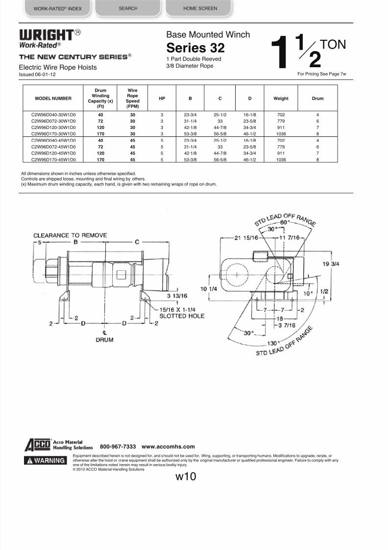
8/21/2019 2013 Wright Specifications Catalog
http://slidepdf.com/reader/full/2013-wright-specifications-catalog 181/189
WORK-RATED® INDEX SEARCH HOME SCREEN
Electric Wire Rope HoistsIssued 06-01-12
Base Mounted Winch
Series 321 Part Double Reeved
3/8 Diameter Rope
All dimensions shown in inches unless otherwise specified.Controls are shipped loose, mounting and final wiring by others.(x) Maximum drum winding capacity, each hand, is given with two remaining wraps of rope on drum.
MODEL NUMBER
Drum
Winding Capacity (x)
(Ft)
Wire
Rope Speed
(FPM)
HP
B
C
D
Weight
Drum
C2W96D040-30W1D0 40 30 3 23-3/4 25-1/2 16-1/8 702 4
C2W96D072-30W1D0 72 30
3
31-1/4
33
23-5/8
779
6
C2W96D120-30W1D0 120 30 3 42-1/8 44-7/8 34-3/4 911 7
C2W96D170-30W1D0 170 30 3 53-3/8 56-5/8 46-1/2 1036 8
C2W96D040-45W1D0 40 45 5 23-3/4 25-1/2 16-1/8 702 4
C2W96D072-45W1D0 72 45 5 31-1/4 33 23-5/8 779 6
C2W96D120-45W1D0 120 45
5
42·1/8
44-7/8
34-3/4
911
7
C2W96D170-45W1D0 170 45
5
53-3/8
56-5/8
46-1/2
1036
8
w10
Equipment described herein is not designed for, and should not be used for, lifting, supporting, or transporting humans. Modifications to upgrade, rerate, orotherwise alter the hoist or crane equipment shall be authorized only by the original manufacturer or qualified professional engineer. Failure to comply with anyone of the limitations noted herein may result in serious bodily injury.© 2012 ACCO Material Handling Solutions
800-967-7333 www.accomhs.com
For Pricing See Page 7w
TON 11
2

8/21/2019 2013 Wright Specifications Catalog
http://slidepdf.com/reader/full/2013-wright-specifications-catalog 182/189
WORK-RATED® INDEX SEARCH HOME SCREEN
Electric Wire Rope HoistsIssued 06-01-12
Base Mounted Winch
Series 331 Part Double Reeved
3/8 Diameter Rope
All dimensions shown in inches unless otherwise specified.Controls are shipped loose, mounting and final wiring by others.(x) Maximum drum winding capacity, each hand, is given with two remaining wraps of rope on drum.
MODEL NUMBER
Drum
Winding Capacity (x)
(Ft)
Wire
Rope Speed
(FPM)
HP
B
C
D
Weight
Drum
C3W96D040-60W1D0 40 60
7-1/2
21-1/2
23-1/4
13-7/8
994
2
C3W96D072-60W1D0 72 60
7-1/2
27
28-3/4
19-3/8
1074
3
C3W96D108-60W1D0 108 60 7-1/2 33-1/2 35-1/4 25-7/8 1167 4
C3W96D164-60W1D0 164 60 7-1/2 43-1/2 45-1/4 35-7/8 1312 5
C3W96D236-60W1D0 236 60
7-1/2
56
57-3/4
48-3/8
1493
6
w11
Equipment described herein is not designed for, and should not be used for, lifting, supporting, or transporting humans. Modifications to upgrade, rerate, orotherwise alter the hoist or crane equipment shall be authorized only by the original manufacturer or qualified professional engineer. Failure to comply with anyone of the limitations noted herein may result in serious bodily injury.© 2012 ACCO Material Handling Solutions
800-967-7333 www.accomhs.com
For Pricing See Page 7w
TON11
2

8/21/2019 2013 Wright Specifications Catalog
http://slidepdf.com/reader/full/2013-wright-specifications-catalog 183/189
WORK-RATED® INDEX SEARCH HOME SCREEN
Electric Wire Rope HoistsIssued 06-01-12
Base Mounted Winch
Series 321 Part Double Reeved
3/8 Diameter Rope
All dimensions shown in inches unless otherwise specified.Controls are shipped loose, mounting and final wiring by others.(x) Maximum drum winding capacity, each hand, is given with two remaining wraps of rope on drum.
MODEL NUMBER
Drum
Winding Capacity (x)
(Ft)
Wire
Rope Speed
(FPM)
HP
B
C
D
Weight
Drum
C2W95D040-30W1D0 40 30
5
23-3/4
25-1/2
16-1/8
702
4
C2W95D072-30W1D0 72 30 5 31-1/4 33 23-5/8 779 6
C2W95D120-30W1D0 120 30 5 42-1/8 44-7/8 34-3/4 911 7
C2W95D170-30W1D0 170 30
5
53-3/8
56-5/8
46-1/2
1036
8
w12
Equipment described herein is not designed for, and should not be used for, lift ing, supporting, or transporting humans. Modifications to upgrade, rerate, orotherwise alter the hoist or crane equipment shall be authorized only by the original manufacturer or qualified professional engineer. Failure to comply with anyone of the limitations noted herein may result in serious bodily injury.© 2012 ACCO Material Handling Solutions
800-967-7333 www.accomhs.com
For Pricing See Page 8w
TON 21
2

8/21/2019 2013 Wright Specifications Catalog
http://slidepdf.com/reader/full/2013-wright-specifications-catalog 184/189
WORK-RATED® INDEX SEARCH HOME SCREEN
Electric Wire Rope HoistsIssued 06-01-12
Base Mounted Winch
Series 331 Part Double Reeved
3/8 Diameter Rope
All dimensions shown in inches unless otherwise specified.Controls are shipped loose, mounting and final wiring by others.(x) Maximum drum winding capacity, each hand, is given with two remaining wraps of rope on drum.
MODEL NUMBER
Drum
Winding Capacity (x)
(Ft)
Wire
Rope Speed
(FPM)
HP
B
C
D
Weight
Drum
C3W95D040-44W1D0 40 44
7-1/2
21-1/2
23-1/4
13-7/8
994
2
C3W95D072-44W1D0 72 44
7-1/2
27
28-3/4
19-3/8
1074
3
C3W95D108-44W1D0 108 44 7-1/2 33-1/2 35-1/4 25-7/8 1167 4
C3W95D164-44W1D0 164 44 7-1/2 43-1/2 45-1/4 35-7/8 1312 5
C3W95D236-44W1D0 236 44
7-1/2
56
57-3/4
48-3/8
1493
6
C3W95D040-60W1D0 40 60
10
21-1/2
23-1/4
13-7/8
994
2
C3W95D072-60W1D0 72 60
10
27
28-3/4
19-3/8
1074
3
C3W95D108-60W1D0 108 60
10
33-1/2
35-1/4
25-7/8
1167
4
C3W95D164-60W1D0 164 60 10 43-1/2 45-1/4 35-7/8 1312 5
C3W95D236-60W1D0 236 60 10 56 57-3/4 48-3/8 1493 6
w13
Equipment described herein is not designed for, and should not be used for, lifting, supporting, or transporting humans. Modifications to upgrade, rerate, orotherwise alter the hoist or crane equipment shall be authorized only by the original manufacturer or qualified professional engineer. Failure to comply with anyone of the limitations noted herein may result in serious bodily injury.© 2012 ACCO Material Handling Solutions
800-967-7333 www.accomhs.com
For Pricing See Page 8w
TON21
2

8/21/2019 2013 Wright Specifications Catalog
http://slidepdf.com/reader/full/2013-wright-specifications-catalog 185/189
WORK-RATED® INDEX SEARCH HOME SCREEN
Electric Wire Rope HoistsIssued 06-01-12
Base Mounted Winch
Series 341 Part Double Reeved
1/2 Diameter Rope
All dimensions shown in inches unless otherwise specified.Controls are shipped loose, mounting and final wiring by others.(x) Maximum drum winding capacity, each hand, is given with two remaining wraps of rope on drum.
MODEL NUMBER
Drum
Winding Capacity (x)
(Ft)
Wire
Rope Speed
(FPM)
HP
B
C
D
Weight
Drum
C4W95D040-85W1D0 40 85 15 24-1/2 30-3/8 17-3/8 1900 2
C4W95D063-85W1D0 63 85 15 29 34-7/8 21-7/8 2050 3
C4W95D095-85W1D0 95 85
15
35
40-7/8
27-7/8
2190
4
C4W95D152-85W1D0 152 85
15
46
51-7/8
38-7/8
2470
5
C4W95D231-85W1D0 231 85 15 61 66-7/8 53-7/8 2850 6
w14
Equipment described herein is not designed for, and should not be used for, lifting, supporting, or transporting humans. Modifications to upgrade, rerate, orotherwise alter the hoist or crane equipment shall be authorized only by the original manufacturer or qualified professional engineer. Failure to comply with anyone of the limitations noted herein may result in serious bodily injury.© 2012 ACCO Material Handling Solutions
800-967-7333 www.accomhs.com
For Pricing See Page 8w
TON 21
2

8/21/2019 2013 Wright Specifications Catalog
http://slidepdf.com/reader/full/2013-wright-specifications-catalog 186/189
WORK-RATED® INDEX SEARCH HOME SCREEN
Electric Wire Rope HoistsIssued 06-01-12
Base Mounted Winch
Series 341 Part Double Reeved1/2 Diameter Rope
All dimensions shown in inches unless otherwise specified.Controls are shipped loose, mounting and final wiring by others.(x) Maximum drum winding capacity, each hand, is given with two remaining wraps of rope on drum.
MODEL NUMBER
Drum
Winding Capacity (x)
(Ft)
Wire
Rope Speed
(FPM)
HP
B
C
D
Weight
Drum
C4W97D040-60W1D0 40 60
15
24-1/2
30-3/8
17-3/8
1900
2
C4W97D063-60W1D0 63 60 15 29 34-7/8 21-7/8 2050 3
C4W97D095-60W1D0 95 60 15 35 40-7/8 27-7/8 2190 4
C4W97D152-60W1D0 152 60
15
46
51-7/8
38-7/8
2470
5
C4W97D231-60W1D0 231 60
15
61
66-7/8
53-7/8
2850
6
w15
Equipment described herein is not designed for, and should not be used for, lifting, supporting, or transporting humans. Modifications to upgrade, rerate, orotherwise alter the hoist or crane equipment shall be authorized only by the original manufacturer or qualified professional engineer. Failure to comply with anyone of the limitations noted herein may result in serious bodily injury.© 2012 ACCO Material Handling Solutions
800-967-7333 www.accomhs.com
For Pricing See Page 9w
TON33
4

8/21/2019 2013 Wright Specifications Catalog
http://slidepdf.com/reader/full/2013-wright-specifications-catalog 187/189
WORK-RATED® INDEX SEARCH HOME SCREEN
Electric Wire Rope HoistsIssued 06-01-12
Base Mounted Winch
Series 351 Part Double Reeved1/2 Diameter Rope
MODEL NUMBER
Drum
Winding Capacity (x)
(Ft)
Wire
Rope Speed
(FPM)
HP
B
C
D
Weight
Drum
C5W97D048-88W1D0 48 88
20
24-7/8
31-5/8
17-3/8
2375
2
C5W97D076-88W1D0 76 88 20 29-3/8 36-1/8 21-7/8 2525 3
C5W97D114-88W1D0 114 88 20 35-3/8 42-1/8 27-7/8 2730 4
C5W97D170-88W1D0 170 88
20
44-3/8
51-1/8
36-7/8
3030
5
C5W97D248-88W1D0 248 88
20
56-7/8
63-5/8
49-3/8
3455
6
All dimensions shown in inches unless otherwise specified.Controls are shipped loose, mounting and final wiring by others.(x) Maximum drum winding capacity, each hand, is given with two remaining wraps of rope on drum.
w16
Equipment described herein is not designed for, and should not be used for, lifting, supporting, or transporting humans. Modifications to upgrade, rerate, orotherwise alter the hoist or crane equipment shall be authorized only by the original manufacturer or qualified professional engineer. Failure to comply with anyone of the limitations noted herein may result in serious bodily injury.© 2012 ACCO Material Handling Solutions
800-967-7333 www.accomhs.com
For Pricing See Page 9w
TON 33
4

8/21/2019 2013 Wright Specifications Catalog
http://slidepdf.com/reader/full/2013-wright-specifications-catalog 188/189
WORK-RATED® INDEX SEARCH HOME SCREEN
Electric Wire Rope HoistsIssued 06-01-12
Base Mounted Winch
Series 351 Part Double Reeved1/2 Diameter Rope
All dimensions shown in inches unless otherwise specified.Controls are shipped loose, mounting and final wiring by others.(x) Maximum drum winding capacity, each hand, is given with two remaining wraps of rope on drum.
MODEL NUMBER
Drum
Winding
Capacity (x) (Ft)
Wire
Rope
Speed
(FPM)
HP B C D Weight Drum
C5W05D048-60W1D0 48 60
20
24-7/8
31-5/8
17-3/8
2375
2
C5W05D076-60W1D0 76 60 20 29-3/8 36-1/8 21-7/8 2525 3
C5W05D114-60W1D0 114 60
20
35-3/8
42-1/8
27-7/8
2730
4
C5W05D170-60W1D0 170 60
20
44-3/8
51-1/8
36-7/8
3030
5
C5W05D248-60W1D0 248 60 20 56-7/8 63-5/8 49-3/8 3455 6
w17
Equipment described herein is not designed for, and should not be used for, lifting, supporting, or transporting humans. Modifications to upgrade, rerate, orotherwise alter the hoist or crane equipment shall be authorized only by the original manufacturer or qualified professional engineer. Failure to comply with anyone of the limitations noted herein may result in serious bodily injury.© 2012 ACCO Material Handling Solutions
800-967-7333 www.accomhs.com
TON5For Pricing See Page 10

8/21/2019 2013 Wright Specifications Catalog
http://slidepdf.com/reader/full/2013-wright-specifications-catalog 189/189
WORK-RATED® INDEX SEARCH HOME SCREEN
Electric Wire Rope HoistsIssued 06-01-12
Base Mounted Winch
Series 351 Part Double Reeved9/16 Diameter Rope
MODEL NUMBER
Drum
Winding
Capacity (x) (Ft)
Wire
Rope
Speed
(FPM)
HP B C D Weight Drum
C5W06D040-48W1D0 40 48
20
24-7/8
31-5/8
17-3/8
2375
2
C5W06D064-48W1D0 64
48 20 29-3/8 36-1/8 21-7/8 2525 3
C5W06D096-48W1D0 96
48 20 35-3/8 42-1/8 27-7/8 2730 4
C5W06D144-48W1D0 144
48 20
44-3/8
51-1/8
36-7/8
3030
5
C5W06D211-48W1D0 211
48 20
56-7/8
63-5/8
49-3/8
3455
6
For Pricing See Page 11w
TON 61
4
All dimensions shown in inches unless otherwise specified.Controls are shipped loose, mounting and final wiring by others.(x) Maximum drum winding capacity, each hand, is given with two remaining wraps of rope on drum.


