2013 NFPA 13 AUTOMATIC SPRINKLER REVIEW...
14
2013 NFPA 13 AUTOMATIC SPRINKLER REVIEW REQUIREMENTS Approved/Comply with Comments Disapproved/Resubmit J. C. Ellison Fire Protection Engineer Phone: (404) 371-4963 Project Name: Physical Address: Project No.: Date Received: Date Reviewed: Sprinkler Contractor Contact Information: Please provide information that is checked in the box as indicated below: 14.1.3 Working plans shall be drawn to an indicated scale, on sheets of uniform size, with a plan of each floor (1) Name of owner and occupant (2) Location, including street address (3) Point of compass (4) Full height cross section, or schematic diagram, if required for clarity, including ceiling construction and method of protection for nonmetallic piping (5) Location of partitions (6) Location of fire walls (7) Occupancy class of each area or room (8) Location and size of concealed spaces, closets, attics, and bathrooms (9) Any small enclosures in which no sprinklers are to be installed Darnell D. Fullum, Director/Fire Chief DEKALB COUNTY FIRE RESCUE DEPARTMENT Fire Marshal Division-Chief Antonio Burden, Fire Marshal 330 West Ponce De Leon Avenue, Decatur, Georgia 30030 Phone: 404-371-2776 Fax: 404-687-2430
Transcript of 2013 NFPA 13 AUTOMATIC SPRINKLER REVIEW...

2013 NFPA 13 AUTOMATIC SPRINKLER REVIEW REQUIREMENTS
Approved/Comply with Comments
Disapproved/Resubmit
J. C. Ellison
Fire Protection Engineer Phone: (404) 371-4963
Project Name: Physical Address: Project No.: Date Received: Date Reviewed:
Sprinkler Contractor Contact Information:
Please provide information that is checked in the box as indicated below:
14.1.3 Working plans shall be drawn to an indicated scale, on sheets of uniform size, with a plan of each floor
(1) Name of owner and occupant
(2) Location, including street address
(3) Point of compass
(4) Full height cross section, or schematic diagram, if required for clarity, including ceiling construction and method of protection for nonmetallic piping
(5) Location of partitions
(6) Location of fire walls
(7) Occupancy class of each area or room
(8) Location and size of concealed spaces, closets, attics, and bathrooms
(9) Any small enclosures in which no sprinklers are to be installed
Darnell D. Fullum, Director/Fire Chief
DEKALB COUNTY FIRE RESCUE DEPARTMENT Fire Marshal Division-Chief Antonio Burden, Fire Marshal
330 West Ponce De Leon Avenue, Decatur, Georgia 30030 Phone: 404-371-2776 Fax: 404-687-2430

2
(10) Size of city main in street and whether dead-end or circulating; if dead end, direction and distance to nearest circulating main; and city main test results and system elevation relative to test hydrant. (See A-15.1.8.)
(11) Other sources of water supply, with pressure or elevation
(12) Make, type, and nominal orifice size of sprinklers
(13) Temperature rating and location of high temperature sprinklers
(14) Total area protected by each system on each floor
(15) Number of sprinklers on each riser per floor
(16) Location and size of riser nipples
(17) Type of fitting and joints and location of all welds and bends. The contractor
shall specify on drawing any sections to be shop welded and the type of fittings or formations to be used
(18) Type and locations of hangers, sleeves, braces, and methods of securing
sprinklers when applicable
(19) All control valves, check valves, drain pipes, and test connections
(20) Kind and location of alarm bells
(21) Size and location of standpipe risers, hose outlets, hand hose, monitor nozzles, and related equipment
(22) Private fire service main sizes, lengths, locations, weights, materials, point of
connection to city main; the sizes, types and locations of valves, valve indicators, regulators, meters, and valve pits; and the depth that the top of the pipe is laid below grade
(23) Piping provisions for flushing
(24) Where the equipment is to be installed as an addition to an existing system,
enough of the existing system indicated on the plans to make all conditions clear
(25) For hydraulically designed systems, the information on the hydraulic data nameplate
(26) A graphic representation of the scale used on all plans
(27) Name and address of contractor
(28) Hydraulic reference points shown on the plan that correspond with comparable
reference points on the hydraulic calculation sheets

3
(29) The minimum rate of water application (density), the design area of water application, in-rack sprinkler demand, and the water required for hose streams both inside and outside
(30) The total quantity of water and the pressure required noted at a common reference point for each system
(31) Relative elevations of sprinklers, junction points, and supply or reference points
(32) If room design method is used, all unprotected wall openings throughout the floor protected
(33) The setting for pressure-reducing valves
(34) Information about backflow preventers (manufacturer, size, type)
(35) Information about antifreeze solution used (type and amount)
(36) Size and location of hydrants, showing size and number of outlets and if outlets are to be equipped with independent gate valves. Whether hose houses and equipment are to be provided, and by whom, shall be indicated. Static and residual hydrants that were used in flow tests shall be shown
(37) Size, location and piping arrangement of fire department connections
14.1.4 The working plan submittal shall include manufacturer’s installation instructions for any specially listed equipment, including descriptions, applications, and limitations for any sprinklers, devices, piping, or fittings. 14.2 Water Supply Information. Please provide the following (14.2.1):
(1) Location and elevation of static and residual test gauge with relation to the riser
reference point
(2) Flow location
(3) Static pressure, psi
(4) Residual pressure, psi
(5) Flow, gpm
(6) Date
(7) Time
(8) Test conducted by or information supplied by
(9) Other sources of water supply, with pressure or elevation
4
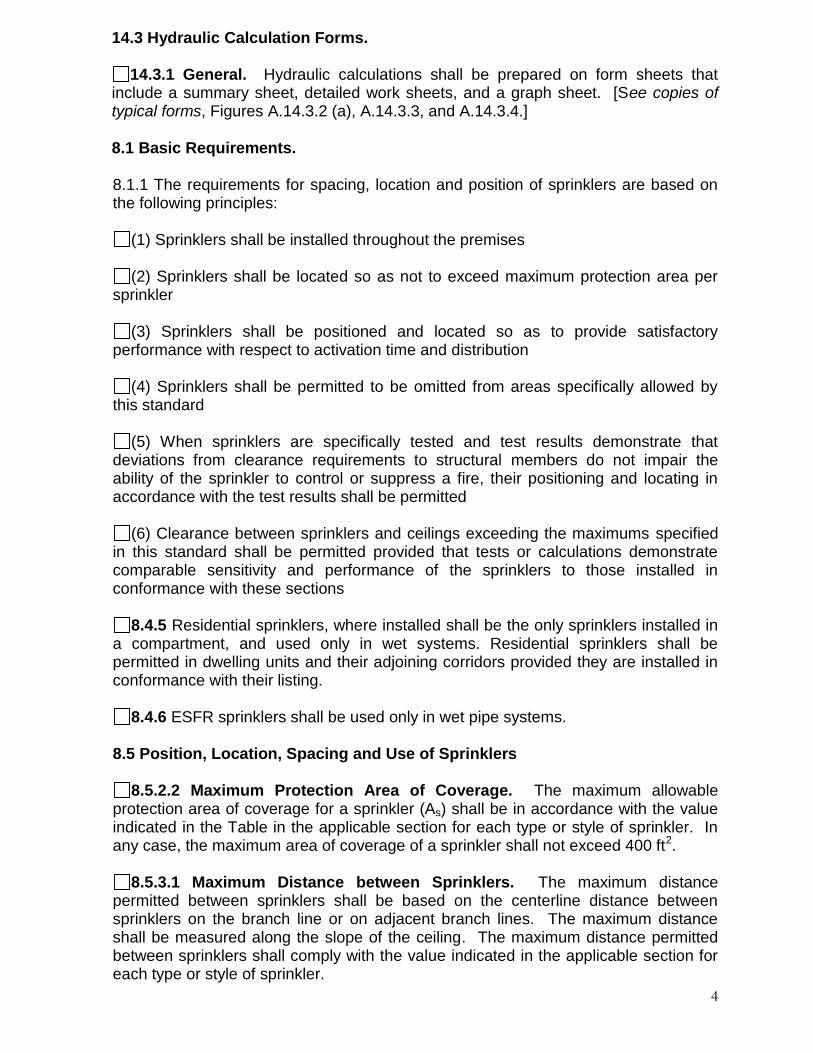
14.3 Hydraulic Calculation Forms.
14.3.1 General. Hydraulic calculations shall be prepared on form sheets that include a summary sheet, detailed work sheets, and a graph sheet. [See copies of typical forms, Figures A.14.3.2 (a), A.14.3.3, and A.14.3.4.] 8.1 Basic Requirements.
8.1.1 The requirements for spacing, location and position of sprinklers are based on the following principles:
(1) Sprinklers shall be installed throughout the premises
(2) Sprinklers shall be located so as not to exceed maximum protection area per
sprinkler
(3) Sprinklers shall be positioned and located so as to provide satisfactory performance with respect to activation time and distribution
(4) Sprinklers shall be permitted to be omitted from areas specifically allowed by this standard
(5) When sprinklers are specifically tested and test results demonstrate that deviations from clearance requirements to structural members do not impair the ability of the sprinkler to control or suppress a fire, their positioning and locating in accordance with the test results shall be permitted
(6) Clearance between sprinklers and ceilings exceeding the maximums specified in this standard shall be permitted provided that tests or calculations demonstrate comparable sensitivity and performance of the sprinklers to those installed in conformance with these sections
8.4.5 Residential sprinklers, where installed shall be the only sprinklers installed in
a compartment, and used only in wet systems. Residential sprinklers shall be permitted in dwelling units and their adjoining corridors provided they are installed in conformance with their listing.
8.4.6 ESFR sprinklers shall be used only in wet pipe systems.
8.5 Position, Location, Spacing and Use of Sprinklers
8.5.2.2 Maximum Protection Area of Coverage. The maximum allowable protection area of coverage for a sprinkler (As) shall be in accordance with the value indicated in the Table in the applicable section for each type or style of sprinkler. In any case, the maximum area of coverage of a sprinkler shall not exceed 400 ft2.
8.5.3.1 Maximum Distance between Sprinklers. The maximum distance
permitted between sprinklers shall be based on the centerline distance between sprinklers on the branch line or on adjacent branch lines. The maximum distance shall be measured along the slope of the ceiling. The maximum distance permitted between sprinklers shall comply with the value indicated in the applicable section for each type or style of sprinkler.

5
8.5.3.2 Maximum Distance from Walls. The distance from sprinklers to walls
shall not exceed one-half of the allowable maximum distance between sprinklers. The distance from the wall to the sprinkler shall be measured perpendicular to the wall.
8.5.3.3 Minimum Distance from Walls. The minimum distance permitted
between a sprinkler and the wall measured perpendicular to the wall shall comply with the value indicated in the applicable section for each type or style of sprinkler. The distance from the wall to the sprinkler shall be no less than 4”.
8.5.3.4 Minimum Distance between Sprinklers. The minimum distance
permitted between sprinklers shall comply with the value indicated in the applicable section for each type or style of sprinkler, and shall be maintained between sprinklers to prevent operating sprinklers from wetting adjacent sprinklers and to prevent skipping of sprinklers. Sprinklers shall be spaced not less than 6ft on center.
ADDITIONAL COMMENTS:
Revised: wbs: 03/12/2014

Revised: wbs: 3/12/2014 1
2013 NFPA 13 MODIFICATION OF EXISTING SPRINKLER SYSTEM REVIEW REQUIREMENTS
Approved/Comply with Comments
Disapproved/Resubmit
Project Name: Physical Address: Project No.: Date Received: Date Reviewed:
Sprinkler Contractor Information:
2013 NFPA 13 MODIFICATION OF EXISTING SPRINKLER SYSTEM REVIEW REQUIREMENTS
All modifications of existing sprinkler systems require submittal of shop drawings, and placement of sprinkler contractor’s new hydraulic data nameplate at the riser or sectional valve along with the existing hydraulic data nameplate.
4.4 In existing sprinkler systems, heads may be relocated from original installation locations.
All alterations or modifications to existing branch lines shall be submitted with hydraulic calculations if work is outside of scope of subsections 4.4.1 through 4.4.4. New hydraulic data nameplate shall be placed on any modified system at the riser or sectional valve along with the existing hydraulic data nameplate. The following modifications of existing sprinkler systems do not require submittal of hydraulic calculations:
4.4.1 One additional sprinkler may be added to an original installation location if the additional sprinkler is in a remotely located or non-communicating compartment from the existing or relocated sprinkler.
DEKALB COUNTY FIRE RESCUE DEPARTMENT Darnell D. Fullum, Director/Fire Chief
Fire Marshal Division-Chief Antonio Burden, Fire Marshal
330 West Ponce De Leon Avenue, Decatur, Georgia 30030 Phone: 404-371-2776 Fax: 404-687-2430

Revised: wbs: 3/12/2014 2
4.4.2 Two sprinklers may be added to an existing branch line if the additional sprinklers are
in remotely located or non-communicating compartments from the existing or relocated sprinkler.
4.4.3 New branch lines added to existing cross mains shall be sized the same as the existing branch lines.
4.4.4 No more than two heads shall be supplied from 1-inch (25.4 mm) pipe unless the existing system was calculated to supply more than two heads. In such case, the calculated maximum for 1-inch (25.4 mm) pipe shall take precedence.
14.1.4 The working plan submittal shall include manufacturer’s installations for any specially listed equipment, including descriptions, applications, and limitations for any sprinklers, devices, piping or fittings.
14.3 Hydraulic Calculation Forms. 14.3.1 General. Hydraulic calculations shall be prepared on form sheets that include a summary sheet, detailed work sheets, and a graph sheet. (See copies of typical forms in Figures A.14.3.2 (a), A.14.3.3, and A.14.3.4.) 14.2 Water Supply Information.
14.2.1 Water Supply Capacity Information. The following information shall be included:
(1) Location and elevation of static and residual test gauge with relation to the riser reference point
(2) Flow location (3) Static pressure, psi (bars) (4) Residual pressure, psi (bars) (5) Flow gpm (L/min) (6) Date (7) Time (8) Test conducted by or information supplied by (9) Other sources of water supply, with pressure or elevation
8.1 Basic Requirements.
8.1.1 The requirements for spacing, location and position of sprinklers are based on the following principles:
(1) Sprinklers installed throughout the premises. (2) Sprinklers located so as not to exceed maximum protection area per sprinkler. (3) Sprinklers positioned and located so as to provide satisfactory performance with
respect to activation time and distribution. (4) Sprinklers shall be permitted to be omitted from areas specifically allowed by this
standard.
Revised: wbs: 3/12/2014 3
(5) When sprinklers are specifically tested and test results demonstrate that deviations from clearance requirements to structural members do not impair the ability of the sprinkler to control or suppress a fire, their positioning and locating in accordance with the test results shall be permitted.
(6) Clearance between sprinklers and ceilings exceeding the maximums specified in this standard shall be permitted provided that tests or calculations demonstrate comparable sensitivity and performance of the sprinklers to those installed in conformance with these sections.

Revised: wbs: 3/12/2014 4
8.5 Position, Location, Spacing and Use of Sprinklers
8.5.2.2 Maximum Protection Area of Coverage. The maximum allowable protection area
of coverage for a sprinkler (As) shall be in accordance with the value indicated in the Table in the applicable section for each type or style of sprinkler. In any case, the maximum area of coverage of a sprinkler shall not exceed 400 ft2.
8.5.3.1 Maximum Distance Between Sprinklers. The maximum distance permitted
between sprinklers shall be based on the centerline distance between sprinklers on the branch line or on adjacent branch lines. The maximum distance shall be measured along the slope of the ceiling. The maximum distance permitted between sprinklers shall comply with the value indicated in the applicable section for each type or style of sprinkler.
8.5.3.2 Maximum Distance from Walls. The distance from sprinklers to walls shall not
exceed one-half of the allowable maximum distance between sprinklers. The distance from the wall to the sprinkler shall be measured perpendicular to the wall.
8.5.3.3 Minimum Distance From Walls. The minimum distance permitted between a
sprinkler and the wall measured perpendicular to the wall shall comply with the value indicated in the applicable section for each type or style of sprinkler. The distance from the wall to the sprinkler shall be no less than 4”.
8.5.3.4 Minimum Distance Between Sprinklers. The minimum distance permitted
between sprinklers shall comply with the value indicated in the applicable section for each type or style of sprinkler, and shall be maintained between sprinklers to prevent operating sprinklers from wetting adjacent sprinklers and to prevent skipping of sprinklers. Sprinklers shall be spaced not less than 6ft on center. ADDITIONAL COMMENTS:

Revised: wbs: 3/12/2014 5

ABOVEGROUND & UNDERGROUND TANK REQUIREMENTS
PROJECT NAME: _________________________________PLAN REVIEW #:___________ ADDRESS: ___________________________________________________________________ DATE: _____________________________ (L/B#:____________________________)
120-3-11-.03 Submission of Plans for Storage Installations.
(1) Plans for all proposed flammable or combustible liquid storage tank installations, including major modifications at existing facilities, with more than a 60 gallon capacity for Class I Liquids or a 120 gallon capacity for Class II and Class III liquids must be submitted in duplicate to the State Fire Marshal for approval, and must be in compliance with applicable codes and standards prior to commencement of construction.
To avoid needless delays in the plan review process, please verify that each of the following is included with your submittal/re-submittal package: I. Two legible, stapled sets of initial submittal or revised re-submittal drawings with permit application:
1. Drawn to 1/8”: OR ¼” 1-0 or as shown on a conventional architects scale. 2. Identifying all areas around the aboveground and underground tanks such as building and property lines. 3. Identify and distinguish all new relocated and/or existing tanks associated with the site. 4. Show proper distances by N. F. P. A. 30 and State Modifications between aboveground tanks and the nearest
public building and property line. II. Complying with applicable provisions of each of the following:
1996 N. F. P. A. 30 Flammable and Combustible Liquids Code and State Modifications 120-3-11
1996 N. F. P. A. 30A Automotive and Marine Service Station Code and State Modifications 120-3-11
2006 International Fire Code and Modifications
1996 N. F. P. A. 407 Standard for Aircraft Fuel Servicing
Georgia Rules and Regulations sec. 120-3-11- Regulations for Flammable and Combustible Liquids. III. Complete detailed and side elevation sheets which include:
Class of fuel, type of U. L. listed tank and capacity of tank
Normal vents, emergency release vents, audible alarm and overfill alarm protection denoting 90% overfill requirements.
95% shut off capacity containment
Show piping diagram
DEKALB COUNTY FIRE RESCUE DEPARTMENT Darnell D. Fullum, Director/Fire Chief
Fire Marshal Division-Chief Antonio Burden, Fire Marshal
330 West Ponce De Leon Avenue, Decatur, Georgia 30030 Phone: 404-371-2776 Fax: 404-687-2430

IV. Spill Prevention Plan – 1996 N. F. P. A. 30 State Modification 12-3-11-07:
Provisions for aboveground tanks larger than 660 gallons shall be made to prevent spills at loading and unloading points from entering public sewers and drainage systems on natural waterways for 110% of the largest compartment on the vehicle used for delivery. Please show spill prevention plan on drawing.
For questions or clarifications regarding these requirements, please call Chief Antonio Burden at 404/371-2776 or e-mail him at [email protected].
For Inspection Appointments please call 404/ 371-3010 *

COMMERCIAL KITCHEN SUPPRESSION SYSTEM
SUBMITTAL REQUIREMENTS
PROJECT NAME: ___________________________________ PLAN REVIEW NO: ______________
ADDRESS: ____________________________________DATE: ____________ (L/B#: ___________)
TO AVOID NEEDLESS DELAYS IN THE PLAN REVIEW PROCESS, PLEASE VERIFY
EACH OF THE FOLLOWING IS INCLUDED WITH YOUR SUBMITTAL/RE-SUBMITTAL
PACKAGE:
A. Please submit a completed HVAC permit application.
B. Three legible stapled sets of initial submittal or revised re-submittal drawings. 1. Drawn to ⅛” or ¼” to 1’ or as verifiable on a conventional architect’s scale, and indicating on plan the
square footage for the scope of work.
2. Complying with applicable provisions of EACH of the following, per 2011 NFPA #96: 10-2.6
a. 2013 NFPA #17A* (Standard for Wet Chemical Extinguishing Systems).
b. 2011 NFPA #96* (Control & Protection of Commercial Cooking Operations).
c. 2012 NFPA #101* (Life Safety Code).
d. 2010 Georgia Accessibility Code (GAC 120-3-20).
e. 2012 International Fire Code*
f. System manufacturer’s ( ) installation and maintenance specifications. [* As modified by the State of Georgia GSFC or GDCA]
3. Incorporate a legend which: a. Identifies by distinct symbols, manufacturer’s name and model number, the quantity and
location of each device comprising the proposed suppression system.
b. Distinguishes between all new, relocated and/or existing appliances to be protected by this
system
4. Providing a layout of the kitchen cooking areas, showing locations of all: a. The labeled cooking appliance(s), fusible links, nozzles and fuel shut-off devices.
b. Exit(s), portable fire extinguisher(s), and manual activation devices.
c. Hood(s), exhaust duct(s), dimensions and a front-to-back cross section diagram of the plenum area to
permit further evolution of protection proposed (per 2012 IFC Sect. 901.2).
d. Sized piping, agent storage container(s). [Per 2011 NFPA #96 10-9.1]
C. Contractors name, signature, State Permit Number, and copy of Contractor’s and System
manufacturer’s installation certification, per 2012 I.F.C., Para 901.2.1 & OCGA T1.25-2-
13d
DEKALB COUNTY FIRE RESCUE DEPARTMENT Darnell D. Fullum, Director/Fire Chief
Fire Marshal Division-Chief Antonio Burden, Fire Marshal 330 West Ponce De Leon Avenue, Decatur, Georgia 30030
Phone: 404-371-2776 Fax: 404-687-2430

D. Include the following on “Job Site”/“Revised” Re-submittal Plan: 1. Pull station located no >20’ nor <10’ from protection hood, en-route to acceptable exit, per 2012
IFC, 904-11.1
2. Class K portable fire extinguisher for cooking equipment involving vegetable and/or animal oils,
in lieu of Class B gas-type or other non-compatible portable extinguishers shall be:
a. Permanently mounted with top of unit n >48” A.F.F., per 2012 IFC, 904-11.5.
b. Located <30’ from protected equipment, per 2010 GAC 120-3-20-.38(3).
3. A statement of intention to provide a placard identifying the use of the above mentioned portable
fire extinguisher as a secondary back-up means to the kitchen suppression system, conspicuously
placing the placards near EACH portable fire extinguisher in the cooking area, per 2011 NFPA
#96:10-2.2.
4. Either a minimum 16” (406mm) separation, or a minimum 8” high steel or tempered glass plate,
between fryer and surface flames of adjacent equipment, per 2011 NFPA #96: 12-1.2.4 and 12-
1.2.5.
5. A minimum 6” overlap of hood beyond open sides of appliance bank, per 2012 I.M.C. Sect.
504.2(1), in lieu of providing architect, engineer, or hood manufacture testing and certification
documentation to this office.
6. Reconciliation of details shown on plan (Sheet____________) with those in manufacturer’s
installation manual (Page_______, Section_____________), per 2012 IFC Sect. 904.11.
7. Fusible link/detector protection per Installation Manual, page______, per 2012 IFC Sect. 904.11.
8. All fire rated wall and floor penetrations must comply with ASTM E-814, per 2012 NFPA #101:
6-2.3.2.4.2.
9. The addition of obstructions to spray patterns from the cooking appliance nozzles such as baffle
plates, shelves, or any modifications shall not be permitted. 2011 NFPA #96-10.2.7.3
E. Miscellaneous: Provide or verify EACH of the following:
____________________________________________________________________________________
____________________________________________________________________________________
____________________________________________________________________________________
Provide, on job site, at time of appointment for final inspection sign-off, in lieu of rescheduling sign-off
for a time when ALL items are available for fire inspector’s review & approval, for return to FMO files.
For questions or clarifications regarding these requirements, please contact the DCFR Fire Marshal’s Office at (404) 371-6208
weekdays between 9:00 p.m. and 3:00 p.m.
Revised: ab: 02/19/2014
Call (404) 371-3010 for DeKalb County permits to schedule Fire Inspector Verification of
Acceptable Life Safety/Accessibility conditions per 2012 IFC Sect. 901.5.