2013 - electricalservices-co.com€¦ · Sistemi di fissaggio per impianti fotovoltaici c atalogo...
76
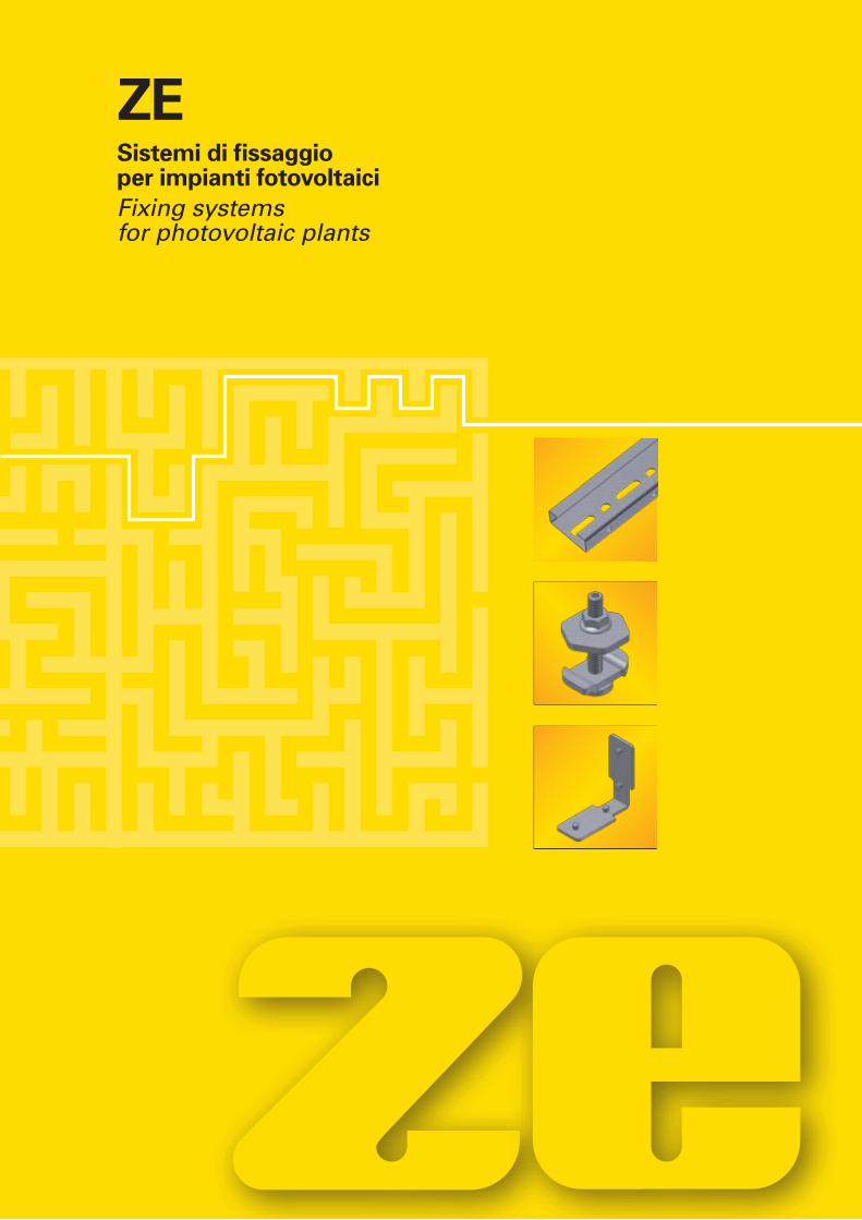
® Edizione Edition 2013 Fixing systems for photovoltaic plants Sistemi di fissaggio per impianti fotovoltaici Catalogo Catalogue 05 ZE
Transcript of 2013 - electricalservices-co.com€¦ · Sistemi di fissaggio per impianti fotovoltaici c atalogo...
®
Ediz
ion
eEd
itio
n 2
013
Fixing systems for photovoltaic plants
Sistemi di fissaggio per impianti fotovoltaici
cat
alog
oC
atal
ogu
e05
ZE

12
52
62
70
SommarioSummary
Indice completoTable of contents
FAX
®
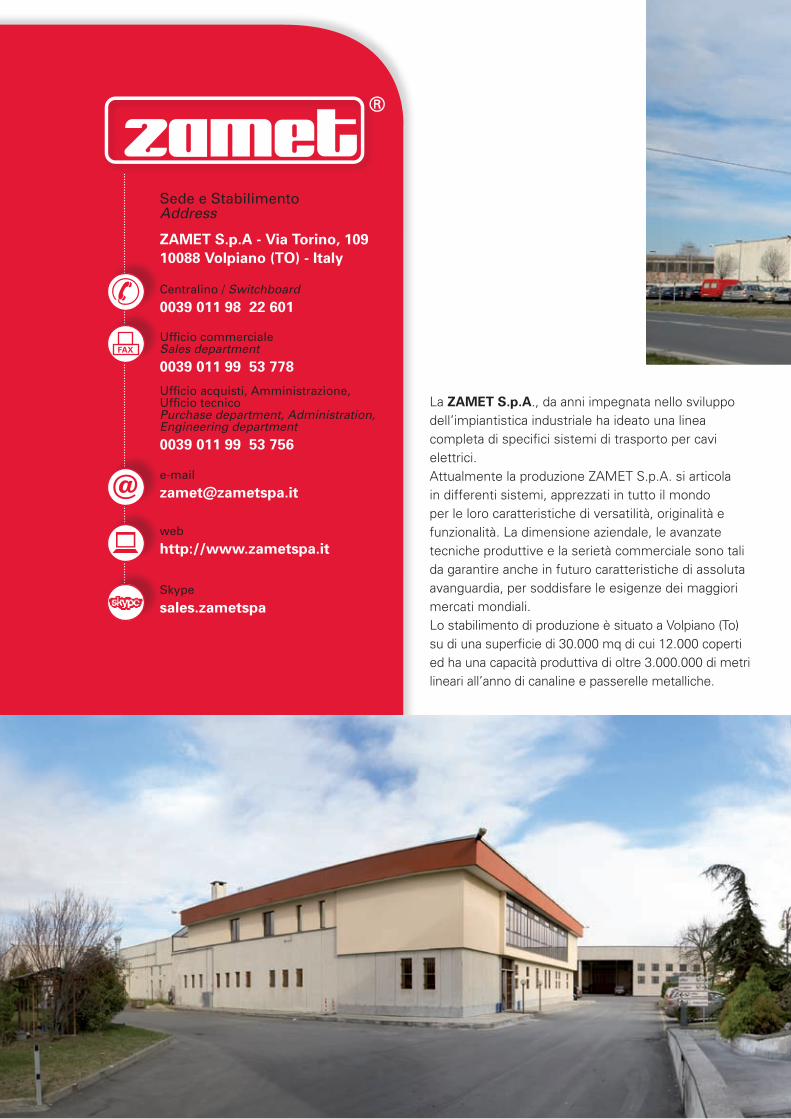
La ZAMET S.p.A., da anni impegnata nello sviluppo dell’impiantistica industriale ha ideato una linea completa di specifici sistemi di trasporto per cavi elettrici.Attualmente la produzione ZAMET S.p.A. si articola in differenti sistemi, apprezzati in tutto il mondo per le loro caratteristiche di versatilità, originalità e funzionalità. La dimensione aziendale, le avanzate tecniche produttive e la serietà commerciale sono tali da garantire anche in futuro caratteristiche di assoluta avanguardia, per soddisfare le esigenze dei maggiori mercati mondiali.Lo stabilimento di produzione è situato a Volpiano (To) su di una superficie di 30.000 mq di cui 12.000 coperti ed ha una capacità produttiva di oltre 3.000.000 di metri lineari all’anno di canaline e passerelle metalliche.
Sede e Stabilimento Address
ZAMET S.p.A - Via Torino, 10910088 Volpiano (TO) - Italy
Centralino / Switchboard
0039 011 98 22 601
Ufficio commerciale Sales department
0039 011 99 53 778
Ufficio acquisti, Amministrazione, Ufficio tecnico Purchase department, Administration, Engineering department
0039 011 99 53 756
web
http://www.zametspa.it
Skype
sales.zametspa
3
Nel catalogo “Passerelle e canaline metalliche per posa cavi elettrici” Zamet S.p.A propone altre serie di
prodotti per altre tipologie di impianto.
On the catalogue "Trunking and cable tray for the conveyance
of electric cables" Zamet S.p.A. suggests other series for other
kind of systems.
Nel catalogo “Passerelle e canaline metalliche per posa cavi a bordo macchina” Zamet S.p.A propone
altre serie di prodotti per altre tipologie di impianto.
On the catalogue "Modular trunking for cable laying around machines"
Zamet S.p.A. suggests other series for other
kind of systems.
Visitando il nostro sito potrete richiedere le certificazioni e la documentazione tecnica specifica di ogni linea
di produzione.
Visiting our website you can ask for the technical documentation specific for each production line.
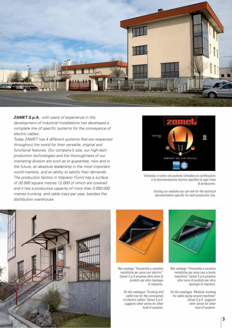
ZAMET S.p.A., with years of experience in the development of Industrial Installations has developed a complete line of specific systems for the conveyance of electric cables.Today ZAMET has 4 different systems that are respected throughout the world for their versatile, original and functional features. Our company’s size, our high-tech production technologies and the thoroughness of our marketing division are such as to guarantee, now and in the future, an absolute leadership in the most important world markets, and an ability to satisfy their demands. The production factory in Volpiano (Turin) has a surface of 30.000 square metres 12.000 of which are covered and it has a productive capacity of more than 3.000.000 metres trunking and cable trays per year, besides the distribution warehouse.
4
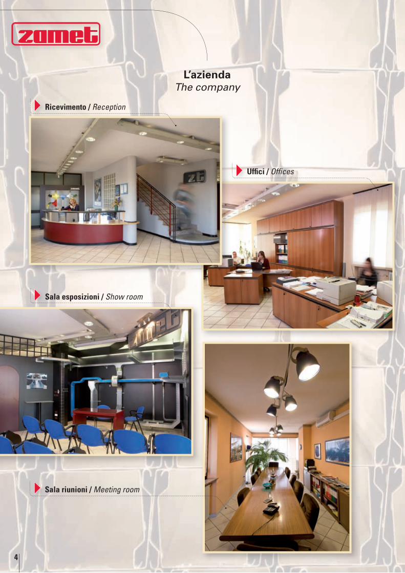
L’aziendaThe company
Ricevimento / Reception
Sala esposizioni / Show room
Uffici / Offices
Sala riunioni / Meeting room
5
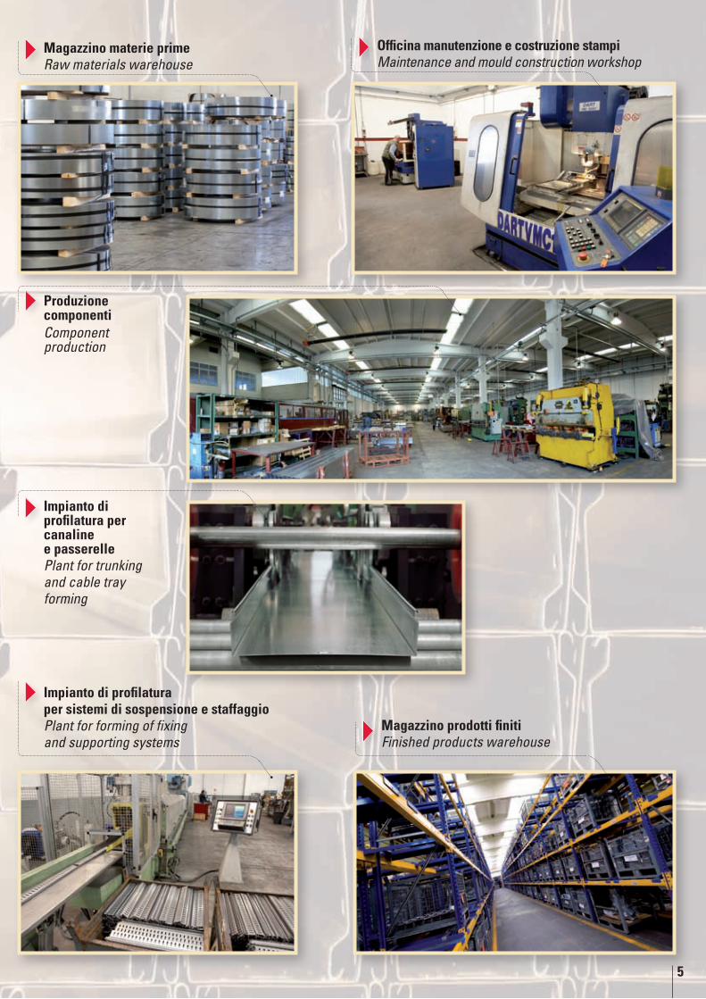
Produzione componentiComponent production
Magazzino prodotti finiti Finished products warehouse
Magazzino materie prime Raw materials warehouse
Officina manutenzione e costruzione stampi Maintenance and mould construction workshop
Impianto di profilatura per sistemi di sospensione e staffaggioPlant for forming of fixing and supporting systems
Impianto di profilatura per canaline e passerellePlant for trunking and cable tray forming
6
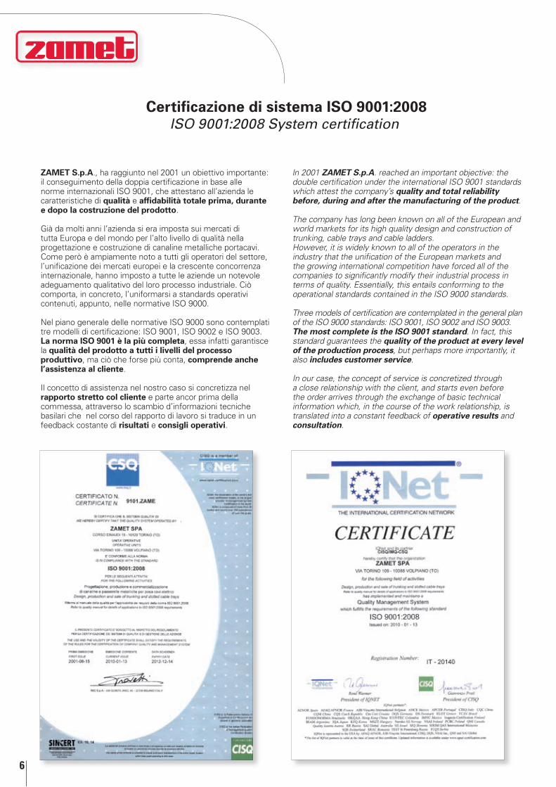
Certificazione di sistema ISO 9001:2008ISO 9001:2008 System certification
ZAMET S.p.A., ha raggiunto nel 2001 un obiettivo importante: il conseguimento della doppia certificazione in base alle norme internazionali ISO 9001, che attestano all’azienda le caratteristiche di qualità e affidabilità totale prima, durante e dopo la costruzione del prodotto.
Già da molti anni l’azienda si era imposta sui mercati di tutta Europa e del mondo per l’alto livello di qualità nella progettazione e costruzione di canaline metalliche portacavi. Come però è ampiamente noto a tutti gli operatori del settore, l’unificazione dei mercati europei e la crescente concorrenza internazionale, hanno imposto a tutte le aziende un notevole adeguamento qualitativo del loro processo industriale. Ciò comporta, in concreto, l’uniformarsi a standards operativi contenuti, appunto, nelle normative ISO 9000.
Nel piano generale delle normative ISO 9000 sono contemplati tre modelli di certificazione: ISO 9001, ISO 9002 e ISO 9003. La norma ISO 9001 è la più completa, essa infatti garantisce la qualità del prodotto a tutti i livelli del processo produttivo, ma ciò che forse più conta, comprende anche l’assistenza al cliente.
Il concetto di assistenza nel nostro caso si concretizza nel rapporto stretto col cliente e parte ancor prima della commessa, attraverso lo scambio d’informazioni tecniche basilari che nel corso del rapporto di lavoro si traduce in un feedback costante di risultati e consigli operativi.
In 2001 ZAMET S.p.A. reached an important objective: the double certification under the international ISO 9001 standards which attest the company’s quality and total reliability before, during and after the manufacturing of the product.
The company has long been known on all of the European and world markets for its high quality design and construction of trunking, cable trays and cable ladders. However, it is widely known to all of the operators in the industry that the unification of the European markets and the growing international competition have forced all of the companies to significantly modify their industrial process in terms of quality. Essentially, this entails conforming to the operational standards contained in the ISO 9000 standards.
Three models of certification are contemplated in the general plan of the ISO 9000 standards: ISO 9001, ISO 9002 and ISO 9003. The most complete is the ISO 9001 standard. In fact, this standard guarantees the quality of the product at every level of the production process, but perhaps more importantly, it also includes customer service.
In our case, the concept of service is concretized through a close relationship with the client, and starts even before the order arrives through the exchange of basic technical information which, in the course of the work relationship, is translated into a constant feedback of operative results and consultation.
7
Che cosa sono gli acciai inossidabiliWhat are stainless steels
Gli acciai inossidabili sono delle leghe a base di Ferro, Cromo e Carbonio, contenenti eventualmente altri elementi come Nichel, Molibdeno, Silicio, Titanio ecc.Sono definiti inossidabili perché alla presenza di un ambiente ossidante (quindi anche l’aria) si forma sulla loro superficie una strato protettivo costituito da Ossigeno adsorbito.Questo strato invisibile, costituisce una barriera al proseguimento dell’ossidazione e quindi della corrosione. Condizione indispensabile perché tale strato protettivo si formi è la presenza di una quantità sufficiente di Cromo; l’Euronorm 88-71 definisce acciai inossidabili quelle leghe ferrose che contengono Cromo in ragione di almeno l’11%.In relazione al loro comportamento strutturale gli acciai inossidabili si possono dividere in tre categorie fondamentali:
Martensitici• , a struttura variabile in funzione della temperatura e quindi induribili per trattamento termico.I tipi caratteristici contengono circa il 13% di Cromo e piccole quantità di altri elementi in lega quali il Nichel ad esempio, in quantità mai superiore al 2,5%Ferritici• , a struttura ferritica stabile indipendente dalla temperatura. I tipi caratteristici contengono circa il 17% di Cromo e tenori di Carbonio molto bassi, solitamente al di sotto dello 0,1%.Austenitici• , a struttura austenitica stabile indipendente dalla temperatura. I tipi caratteristici contengono Cromo in quantità superiore al 17% e Nichel in quantità superiore al 7%.
I sistemi di canaline metalliche in acciaio inox della Zamet S.p.A. trovano largo impiego nel settore alimentare, navale, gallerie autostradali, chimico, farmaceutico ed allevamento.
The stainless steels are alloys based on Iron, Chromium and Carbon, possibly containing other elements like Nickel, Molybdenum, Silicon, Titanium, etc.They are defined stainless because in the presence of an oxidising environment (therefore also air), a protective layer made up of absorbed Oxygen forms on their surface.This invisible layer constitutes a barrier to the continuation of the oxidation and therefore of corrosion. In order for this protective layer to form, a sufficient quantity of Chromium is indispensable, Euronorm 88-71 defines as stainless steels those ferrous alloys which contain at least 11% Chromium. In relation to their structural behaviour, stainless steels may be divided into three fundamental categories:
• Martensitics, a structure which varies in function of temperature and therefore hardenable through heat-treating. The characteristic types contain about 13% Chromium and small quantities of other elements in allow, like Nickel for example, in quantities that never exceed 2.5%.
• Ferritics, of stable ferritic structure regardless of the temperature. The characteristic types contain about 17% Chromium and very low levels of Carbon, usually less than 0.1%.
• Austenitics, stable of austenitic structure regardless of the temperature. The characteristic types contain about 17% Chromium and Nickel in quantities greater than 7%
The Zamet S.p.A. trunking and cable trays in stainless steel are widely used in the food, naval, highway tunnel, chemical, pharmaceutical and animal breeding industries.
8
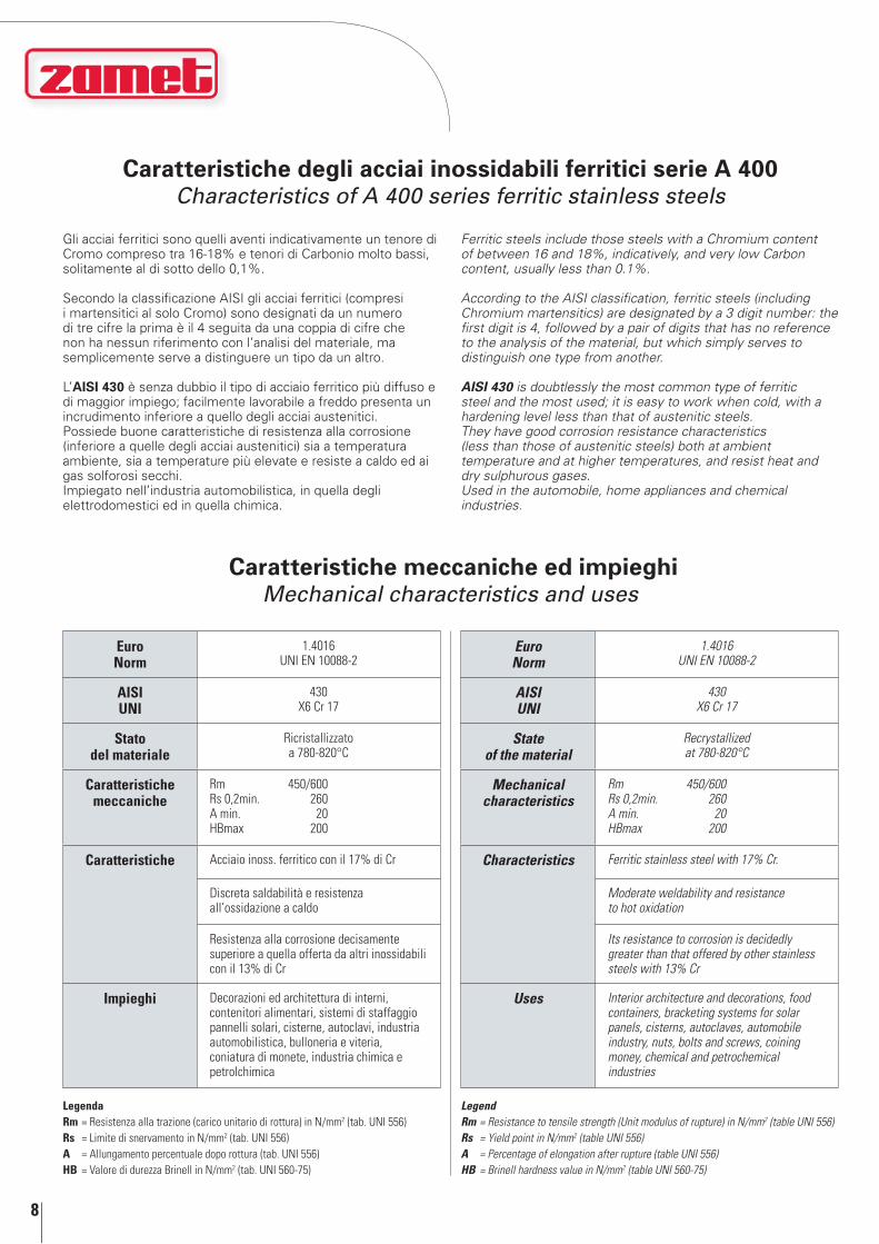
Caratteristiche meccaniche ed impieghiMechanical characteristics and uses
LegendaRm = Resistenza alla trazione (carico unitario di rottura) in N/mm2 (tab. UNI 556)Rs = Limite di snervamento in N/mm2 (tab. UNI 556)A = Allungamento percentuale dopo rottura (tab. UNI 556)HB = Valore di durezza Brinell in N/mm2 (tab. UNI 560-75)
LegendRm = Resistance to tensile strength (Unit modulus of rupture) in N/mm2 (table UNI 556)Rs = Yield point in N/mm2 (table UNI 556)A = Percentage of elongation after rupture (table UNI 556)HB = Brinell hardness value in N/mm2 (table UNI 560-75)
Euro Norm
1.4016UNI EN 10088-2
AISI UNI
430 X6 Cr 17
Stato del materiale
Ricristallizzato a 780-820°C
Caratteristichemeccaniche
Rm 450/600 Rs 0,2min. 260 A min. 20 HBmax 200
Caratteristiche Acciaio inoss. ferritico con il 17% di Cr
Discreta saldabilità e resistenza all’ossidazione a caldo
Resistenza alla corrosione decisamente superiore a quella offerta da altri inossidabili con il 13% di Cr
Impieghi Decorazioni ed architettura di interni, contenitori alimentari, sistemi di staffaggio pannelli solari, cisterne, autoclavi, industria automobilistica, bulloneria e viteria, coniatura di monete, industria chimica e petrolchimica
Euro Norm
1.4016UNI EN 10088-2
Aisi UNi
430 X6 Cr 17
state of the material
Recrystallized at 780-820°C
Mechanical characteristics
Rm 450/600 Rs 0,2min. 260 A min. 20 HBmax 200
Characteristics Ferritic stainless steel with 17% Cr.
Moderate weldability and resistance to hot oxidation
Its resistance to corrosion is decidedly greater than that offered by other stainless steels with 13% Cr
Uses Interior architecture and decorations, food containers, bracketing systems for solar panels, cisterns, autoclaves, automobile industry, nuts, bolts and screws, coining money, chemical and petrochemical industries
Caratteristiche degli acciai inossidabili ferritici serie A 400Characteristics of A 400 series ferritic stainless steels
Gli acciai ferritici sono quelli aventi indicativamente un tenore di Cromo compreso tra 16-18% e tenori di Carbonio molto bassi, solitamente al di sotto dello 0,1%.
Secondo la classificazione AISI gli acciai ferritici (compresi i martensitici al solo Cromo) sono designati da un numero di tre cifre la prima è il 4 seguita da una coppia di cifre che non ha nessun riferimento con l’analisi del materiale, ma semplicemente serve a distinguere un tipo da un altro.
L’AISI 430 è senza dubbio il tipo di acciaio ferritico più diffuso e di maggior impiego; facilmente lavorabile a freddo presenta un incrudimento inferiore a quello degli acciai austenitici.Possiede buone caratteristiche di resistenza alla corrosione (inferiore a quelle degli acciai austenitici) sia a temperatura ambiente, sia a temperature più elevate e resiste a caldo ed ai gas solforosi secchi.Impiegato nell’industria automobilistica, in quella degli elettrodomestici ed in quella chimica.
Ferritic steels include those steels with a Chromium content of between 16 and 18%, indicatively, and very low Carbon content, usually less than 0.1%.
According to the AISI classification, ferritic steels (including Chromium martensitics) are designated by a 3 digit number: the first digit is 4, followed by a pair of digits that has no reference to the analysis of the material, but which simply serves to distinguish one type from another.
AISI 430 is doubtlessly the most common type of ferritic steel and the most used; it is easy to work when cold, with a hardening level less than that of austenitic steels. They have good corrosion resistance characteristics (less than those of austenitic steels) both at ambient temperature and at higher temperatures, and resist heat and dry sulphurous gases. Used in the automobile, home appliances and chemical industries.
9
01
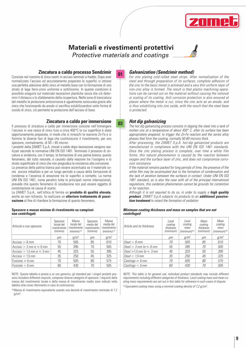
03 Hot dip galvanizingThe hot dip galvanizing process consists in dipping the steel into a tank of molten zinc at a temperature of about 450° C, after its surface has been appropriately prepared, to trigger the Zn-Fe reaction and the series alloy phases that form the coating, normally 50-60 microns thick. After processing, the ZAMET S.p.A. hot-dip galvanized products are manufactured in compliance with the UNI EN ISO 1461 standards. Once the zinc plating process is complete, over time a white film forms; this natural phenomenon is caused by the reaction between oxygen and the surface layer of zinc, and does not compromise corro-sion resistance. If the material remains packed for long periods of time, the presence of the white film may be accentuated due to the formation of condensation and the lack of aeration between the surfaces in contact. Under UNI EN ISO 1461 standard, as is also the case with all of the principal international regulations, this oxidation phenomenon cannot be grounds for contention or for rejection.Although it is not required to do so, in order to supply a high quality product, ZAMET S.p.A subjects its products to an additional passiva-tion treatment to retard the formation of oxidation
Galvanization (sendzimir method)For zinc plating cold-rolled steel strips. After normalisation of the steel and through preparation of its surfaces, complete adhesion of the zinc to the basic metal is achieved and a very thin uniform layer of iron-zinc alloy is formed. The result is that plastic machining opera-tions can be carried out on the material without causing the removal or scaling of its coating. Anti corrosion protection is also ensured at places where the metal is cut, since the zinc acts as an anode, and is thus solubilising into zinc oxide, with the result that the steel base is protected.
Article and its thicknessLocal
coating thickness (minimum)
Local coating mass
(minimum) (a)
Mean coating
thickness (minimum)
Mean coating mass
(minimum) (a)
µm g/m2 µm g/m2
Steel 6 mm 70 505 85 610Steel 3 mm to 6 mm 55 395 70 505Steel 1,5 mm to 3 mm 45 325 55 395Steel 1,5 mm 35 250 45 325Castings 6 mm 70 505 80 575Castings 6 mm 60 430 70 505
Minimum coating thickness and mass on samples that are not centrifuged
NOTE. This table is for general use, individual product standards may include different requirements including different categories of thickness. Local coating mass and mean co-ating mass requirements are set out in this table for reference in such cases of dispute.(a) Equivalent coating mass using a nominal coating density of 7,2 g/cm3.
Articolo e suo spessoreSpessore locale del
rivestimento (minimo)
Massa locale del
rivestimento (minimo) (a)
Spessore medio del
rivestimento (minimo)
Massa media del
rivestimento (minimo) (a)
µm g/m2 µm g/m2
Acciaio 6 mm 70 505 85 610Acciaio 3 mm e 6 mm 55 395 70 505Acciaio 1,5 mm e 3 mm 45 325 55 395Acciaio 1,5 mm 35 250 45 325Fusione 6 mm 70 505 80 575Fusione 6 mm 60 430 70 505
Spessore e masse minime di rivestimento su campioni non centrifugati
NOTE. Questa tabella si presta a un uso generico, gli standard per i singoli prodotti pos-sono includere differenti requisiti, comprese diverse categorie di spessore. I requisiti della massa del rivestimento locale e della massa di rivestimento medio sono indicati nella tabella utile come riferimento in caso di controversia.(a) Massa di rivestimento equivalente usando una densità di rivestimento nominale di 7,2
g/cm3.
Zincatura a caldo per immersioneIl processo di zincatura a caldo per immersione consiste nell’immergere l’acciaio in una vasca di zinco fuso a circa 450°C la cui superficie è stata opportunamente preparata, in modo che si inneschi la reazione Zn-Fe e si formino le diverse fasi di lega che costituiscono il rivestimento, per uno spessore, normalmente, di 50 ÷ 65 micron. I prodotti della ZAMET S.p.A. zincati a caldo dopo lavorazione vengono rea-lizzati secondo le normative UNI EN ISO 1461. Terminato il processo di zin-catura si evidenzia, con il tempo, la formazione di una patina bianca; questo fenomeno, del tutto naturale, è causato dalla reazione tra l’ossigeno e lo strato superficiale di zinco che non pregiudica la resistenza alla corrosione.La presenza della patina bianca può essere accentuata se il materiale so-sta ancora imballato e per un lungo periodo a causa della formazione di condensa e l’assenza di areazione tra le superfici a contatto. La norma UNI EN ISO 1461, come peraltro tutte le principali norme internazionali, prevede che questo fenomeno di ossidazione non può essere oggetto di contestazione né causa di scarto.La ZAMET S.p.A., nell’ottica di fornire un prodotto di qualità elevata, anche se non richiesto, fa realizzare un ulteriore trattamento di passi-vazione al fine di ritardare la formazione di questo fenomeno.
Zincatura a caldo processo SendzimirConsiste nel rivestire di zinco nastri in acciaio laminati a freddo. Dopo aver normalizzato l’acciaio ed accuratamente preparato le superfici si ottiene una perfetta adesione dello zinco al metallo base con la formazione di uno strato di lega ferro-zinco uniforme e sottilissimo. In queste condizioni è possibile eseguire sul materiale lavorazioni plastiche senza che ciò deter-mini il distacco o lo sfaldamento della ricopertura. Nelle zone di tranciatura del metallo la protezione anticorrosiva è ugualmente assicurata grazie allo zinco che funzionando da anodo si sacrifica solubilizzandosi sotto forma di ossido di zinco, ciò permette la protezione dell’acciaio di base.
Materiali e rivestimenti protettiviProtective materials and coatings

10
Materiali e rivestimenti protettiviProtective materials and coatings
40
41
47
76
73
75
stainless steelAISI 304 - Cr-Ni steel with low percentage of C, austenitic, not hardenable, corrosion-resistant. Non magnetic when annealed, slightly magnetic when cold worked. Good weldability and fairly good resistance to intercrystalline corrosion. Very good toughness up to very low temperatures.X5CrNi18-10 • D.no. 1.4301• Pmax = 0.045 • C ≤ 0.07 • Si ≤ 1.0 • Mn ≤ 2.0 S ≤ 0.015 • N ≤ 0.11 • Cr 17.5 to 19.5 • Ni 8.0 to 10.5
AISI 316L - Excellent corrosion resistance in atmosphere and in a large variety of salts, organic acids and foodstuffs, discreet with regard to weak reductant acid solutions, better with respect to the other austenitic steels that do not contain Mo, against halides and sea water.X5CrNiMo17-12-2 • D.no. 1.4401 • Pmax = 0.045 • C ≤ 0.07 • Si ≤ 1.0 • Mn ≤ 2.0 S ≤ 0.015 • N ≤ 0.11 • Cr 16.5 to 18.5 • Mo 2.0 to 2.5 • Ni 10.0 to 13.0
AISI 430 is doubtlessly the most common type of ferritic steel and the most used; it is easy to work when cold, with a hardening level less than that of austenitic steels. They have good corrosion resistance characteristics (less than those of austenitic steels) both at ambient temperature and at higher temperatures, and resist heat and dry sulphurous gases. Used in the automobile, home appliances and chemical industries. - Code 73 refers to AISI 430 treatment.- Code 75 refers to AISI 430 treatment with 1.50 mm thickness.
Geomet® 321Geomet® 321 is a thin coating, non-electrolytic, aluminium grey in col-our, for the protection against the corrosion of articles in steel, cast iron or in other ferrous metals. Geomet® 321 is constituted of zinc and aluminium foils in an inorganic matrix; it was developed by Dacral, the manufacturer of DACROMET® 320, as a 100% chromium free alterna-tive. The application of Geomet® 321 does not generate embrittlement due to hydrogen. The process used is that of cold dipping in an aqueous dispersion or spraying.
Magnelis® ZM 310The Magnelis® is a metal coating that provides optimum protection to sur-faces against the long-term damages.This coating offers a range of unmatched benefits:- Better corrosion resistance, up to 10 times higher than any other galva-
nized steel;- Better protection for surfaces exposed to aggressive environments;- The best alternative in terms of costs-benefits, to the post-galvanizing
process.Magnelis® is produced from a base of hot galvanized steel, which is, how-ever, dipped into a bath that contains a metallic composition of zinc with 3.5% aluminum and 3% magnesium.This 3% of magnesium is crucial, because it results in a stable and re-sistant layer over the entire metal surface, contributing to a more effec-tive defense against corrosion than a coating with a lower content of magnesium.Magnelis® is an innovative product that provides better performance than any other steel.
Acciaio inoxAISI 304 - Acciaio al Cr-Ni a basso tasso di C, austenitico, non temprabile, resistente alla corrosione. Amagnetico allo stato ricotto, leggermente ma-gnetico se lavorato a freddo. Buona saldabilità e discreta resistenza alla corrosione intercristallina. Ottima tenacità fino a bassissime temperature.X5CrNi18-10 • D.num. 1.4301• Pmax = 0,045 • C 0,07 • Si 1,0 • Mn 2,0 S 0,015 • N 0,11 • Cr da 17,5 a 19,5 • Ni da 8,0 a 10,5
AISI 316L - Ottima resistenza alla corrosione in atmosfera ed in una gran-de varietà di sali, acidi organici e sostanze alimentari, discreta nei confron-ti delle soluzioni deboli di acidi riducenti, migliore rispetto agli altri acciai austenitici non contenenti Mo, verso gli alogenuri e l’acqua marina.X5CrNiMo17-12-2 • D.num. 1.4401 • Pmax = 0,045 • C 0,07 • Si 1,0 • Mn 2,0 S 0,015 • N 0,11 • Cr da 16,5 a 18,5 • Mo da 2,0 a 2,5 • Ni da 10,0 a 13,0
L’AISI 430 è senza dubbio il tipo di acciaio ferritico più diffuso e di maggior impiego; facilmente lavorabile a freddo presenta un incrudimento inferiore a quello degli acciai austenitici.Possiede buone caratteristiche di resistenza alla corrosione (inferiore a quelle degli acciai austenitici) sia a temperatura ambiente, sia a tempera-ture più elevate e resiste a caldo ed ai gas solforosi secchi.Impiegato nell’industria automobilistica, in quella degli elettrodomestici ed in quella chimica.- Il codice 73 corrisponde al trattamento AISI 430.- Il codice 75 corrisponde al trattamento AISI 430 con spessore 1,50 mm.
Geomet® 321Il Geomet® 321 è un rivestimento sottile, non elettrolitico, di colore gri-gio alluminio, per la protezione contro la corrosione di pezzi in acciaio, in ghisa o in altri metalli ferrosi. Il Geomet® 321 è costituito da lamelle di zinco e d’alluminio in una matrice inorganica, è stato sviluppato da Dacral, fabbricante del DACROMET® 320, come alternativa 100% senza cromo. L’applicazione del Geomet® 321 non genera infragilimento da idrogeno. Il processo utilizzato è l’immersione a freddo in una dispersione acquosa o la spruzzatura.
Magnelis® ZM 310Il Magnelis® è un rivestimento metallico che assicura una protezione otti-male alle superfici contro i danni a lungo termine.Questo rivestimento offre una serie di vantaggi ineguagliabili:- migliore resistenza alla corrosione, fino a 10 volte superiore ad ogni altro
acciaio zincato;- migliore protezione per le superfici esposte ad ambienti particolarmente
aggressivi;- migliore alternativa, in termini di rapporto costo-benefici, al processo di
post-zincatura.Magnelis® è prodotto a partire da una linea classica di acciaio zincato a caldo, che viene però immerso in un bagno che contiene una composizione metallica particolare di zinco con il 3.5% di alluminio e il 3% di magnesio. Questo 3% di magnesio è cruciale, perchè determina uno strato stabile e resistente lungo l'intera superficie metallica, contribuendo a rendere più efficace la difesa alla corrosione rispetto a un rivestimento con un conte-nuto inferiore di magnesio.Magnelis® è un prodotto innovativo e garantisce delle performance miglio-ri rispetto a qualsiasi altro acciaio zincato.
11
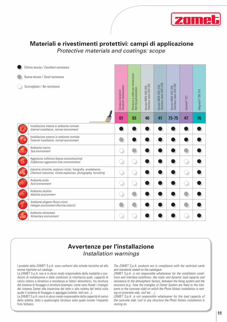
Materiali e rivestimenti protettivi: campi di applicazioneProtective materials and coatings: scope
Zinc
atur
a Se
ndzim
irSe
ndzim
ir Ga
lvani
zatio
n
Zinc
atur
a a
cald
o pe
r im
mer
sion
eHo
t dip
gal
vani
zatio
n
Acci
aio
INOX
AIS
I 304
Stai
nles
s st
eel A
ISI 3
04
Acci
aio
INOX
AIS
I 316
LSt
ainl
ess
stee
l AIS
I 316
L
Acci
aio
INOX
AIS
I 430
Stai
nles
s st
eel A
ISI 4
30
Geom
et®
321
Mag
nelis
® Z
M 3
10
01 03 40 41 73-75 47 76
Installazione interna in ambiente normale Internal installation, normal environment
Installazione esterna in ambiente normale External installation, normal environment
Ambiente marino Sea environment
Aggressivo solforoso (bassa concentrazione) Sulphurous aggressive (low concentration)
Industrie chimiche, esplosivi nitrati, fotografia, arredamento Chemical industries, nitrate explosives, photography, furnishing
Ambiente acido Acid environment
Ambiente alcalino Alkaline environment
Ambiente alogeno (fluoro-cloro) Halogen environment (fluorine-chlorin)
Ambiente alimentare Alimentary environment
Ottima tenuta / Excellent resistance
Buona tenuta / Good resistance
Sconsigliato / No resistance
Avvertenze per l'installazioneInstallation warnings
I prodotti della ZAMET S.p.A. sono conformi alle schede tecniche ed alle norme riportate sul catalogo.La ZAMET S.p.A. non è in alcun modo responsabile delle modalità e con-dizioni di installazione e delle condizioni di interfaccia quali, capacità di carico statico e dinamico e resistenza ai fattori atmosferici, tra struttura del sistema di fissaggio e struttura (esempio: come sono fissati i triangoli del sistema Zamet alle traversine del tetto o alla soletta del tetto) sulla quale il sistema di fissaggio si appoggia (solette, tetti ecc...). La ZAMET S.p.A. non è in alcun modo responsabile della capacità di carico della soletta, tetto o qualsivoglia struttura sulla quale insiste l’impianto Foto Voltaico.
The ZAMET S.p.A. products are in compliance with the technical cards and standards stated on the catalogue.ZAMET S.p.A. is not responsible whatsoever for the installation condi-tions and interface conditions, like static and dynamic load capacity and resistance to the atmospheric factors, between the fixing system and the structure (e.g.: how the triangles of Zamet System are fixed to the tran-soms or the concrete slab) on which the Photo Voltaic installation is rest-ing on (concrete slab, roof etc…).ZAMET S.p.A. is not responsible whatsoever for the load capacity of the concrete slab, roof or any structure the Photo Voltaic installation is resting on.
Sistemi di fissaggio per impianti fotovoltaiciFixing systems for photovoltaic plants
ZE
14
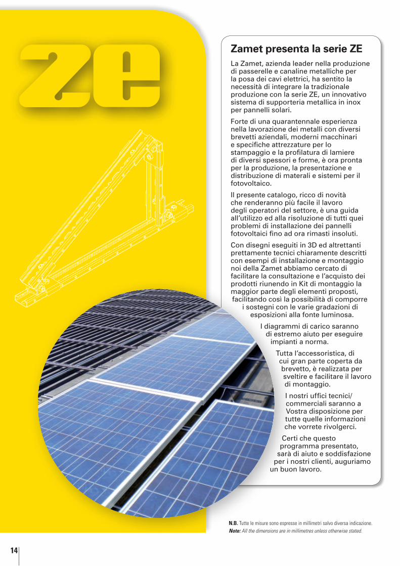
La Zamet, azienda leader nella produzione di passerelle e canaline metalliche per la posa dei cavi elettrici, ha sentito la necessità di integrare la tradizionale produzione con la serie ZE, un innovativo sistema di supporteria metallica in inox per pannelli solari.
Forte di una quarantennale esperienza nella lavorazione dei metalli con diversi brevetti aziendali, moderni macchinari e specifiche attrezzature per lo stampaggio e la profilatura di lamiere di diversi spessori e forme, è ora pronta per la produzione, la presentazione e distribuzione di materali e sistemi per il fotovoltaico.
Il presente catalogo, ricco di novità che renderanno più facile il lavoro degli operatori del settore, è una guida all’utilizzo ed alla risoluzione di tutti quei problemi di installazione dei pannelli fotovoltaici fino ad ora rimasti insoluti.
Con disegni eseguiti in 3D ed altrettanti prettamente tecnici chiaramente descritti con esempi di installazione e montaggio noi della Zamet abbiamo cercato di facilitare la consultazione e l’acquisto dei prodotti riunendo in Kit di montaggio la maggior parte degli elementi proposti, facilitando così la possibilità di comporre
i sostegni con le varie gradazioni di esposizioni alla fonte luminosa.
I diagrammi di carico saranno di estremo aiuto per eseguire
impianti a norma.
Tutta l’accessoristica, di cui gran parte coperta da brevetto, è realizzata per sveltire e facilitare il lavoro di montaggio.
I nostri uffici tecnici/commerciali saranno a Vostra disposizione per tutte quelle informazioni che vorrete rivolgerci.
Certi che questo programma presentato,
sarà di aiuto e soddisfazione per i nostri clienti, auguriamo
un buon lavoro.
Zamet presenta la serie ZE
N.B. Tutte le misure sono espresse in millimetri salvo diversa indicazione.Note: All the dimensions are in millimetres unless otherwise stated.
15
SerieSeries
Famiglia Family
Misura H Dimension H
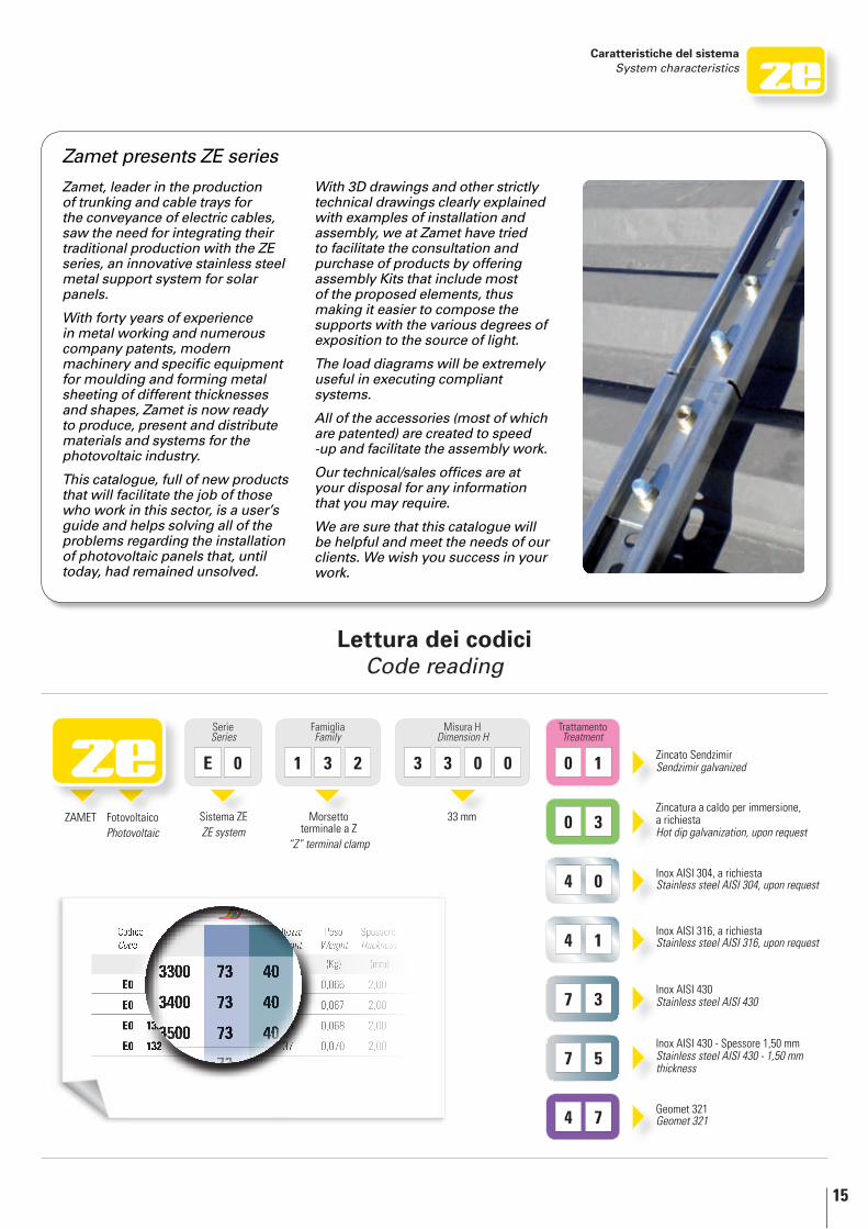
E 0 1 3 2 3 3 0 0
Trattamento Treatment
0 1
7 3
7 5
4 1
4 0
4 7
0 3
Codice Code
ltezza ght
Peso Weight
Spessore Thickness
(Kg) (mm)
E0 0,066 2,00
E0 0,067 2,00
E0 132 5 0,068 2,00
E0 132 37 0,070 2,00
Zamet presents ZE series
Zamet, leader in the production of trunking and cable trays for the conveyance of electric cables, saw the need for integrating their traditional production with the ZE series, an innovative stainless steel metal support system for solar panels.
With forty years of experience in metal working and numerous company patents, modern machinery and specific equipment for moulding and forming metal sheeting of different thicknesses and shapes, Zamet is now ready to produce, present and distribute materials and systems for the photovoltaic industry.
This catalogue, full of new products that will facilitate the job of those who work in this sector, is a user’s guide and helps solving all of the problems regarding the installation of photovoltaic panels that, until today, had remained unsolved.
With 3D drawings and other strictly technical drawings clearly explained with examples of installation and assembly, we at Zamet have tried to facilitate the consultation and purchase of products by offering assembly Kits that include most of the proposed elements, thus making it easier to compose the supports with the various degrees of exposition to the source of light.
The load diagrams will be extremely useful in executing compliant systems.
All of the accessories (most of which are patented) are created to speed -up and facilitate the assembly work.
Our technical/sales offices are at your disposal for any information that you may require.
We are sure that this catalogue will be helpful and meet the needs of our clients. We wish you success in your work.
ZAMET FotovoltaicoPhotovoltaic
Sistema ZEZE system
Morsetto terminale a Z
“Z” terminal clamp
33 mm
Zincato Sendzimir Sendzimir galvanized
Zincatura a caldo per immersione, a richiestaHot dip galvanization, upon request
Inox AISI 304, a richiesta Stainless steel AISI 304, upon request
Inox AISI 316, a richiesta Stainless steel AISI 316, upon request
Inox AISI 430Stainless steel AISI 430
Inox AISI 430 - Spessore 1,50 mmStainless steel AISI 430 - 1,50 mm thickness
Geomet 321 Geomet 321
Lettura dei codiciCode reading
Caratteristiche del sistema System characteristics
16
L
Sistemi di fissaggio per impianti fotovoltaiciFixing systems for photovoltaic plants
03 Zincatura a caldo per immersione a richiesta / Hot dip galvanization upon request
40 Inox AISI 304 a richiesta / Stainless steel AISI 304 upon request 41 Inox AISI 316L a richiesta / Stainless steel AISI 316L upon request 73 Inox AISI 430 / Stainless steel AISI 430 75 Inox AISI 430 sp. 1,50 mm / Stainless steel AISI 430 1,50 mm thick. 76 Magnelis® ZM 310 47 Geomet® 321
Rivestimento /Treatment
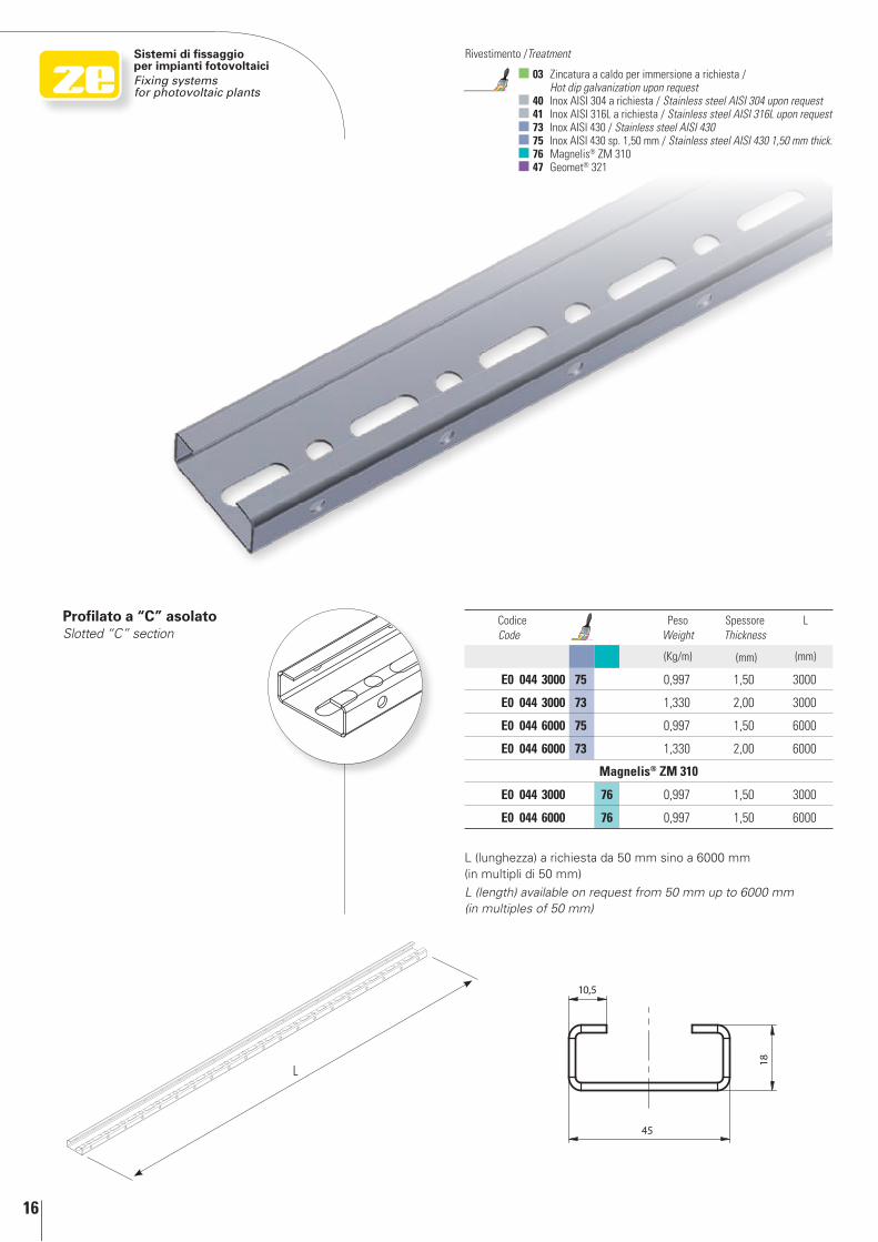
Profilato a “C” asolatoSlotted “C” section
Codice Code
Peso Weight
Spessore Thickness
L
(Kg/m) (mm) (mm)
E0 044 3000 75 0,997 1,50 3000
E0 044 3000 73 1,330 2,00 3000
E0 044 6000 75 0,997 1,50 6000
E0 044 6000 73 1,330 2,00 6000
Magnelis® ZM 310
E0 044 3000 76 0,997 1,50 3000
E0 044 6000 76 0,997 1,50 6000
L (lunghezza) a richiesta da 50 mm sino a 6000 mm (in multipli di 50 mm)
L (length) available on request from 50 mm up to 6000 mm (in multiples of 50 mm)
17
Sistemi di fissaggio per impianti fotovoltaici
Fixing systems for photovoltaic plants
In praticaIn practice
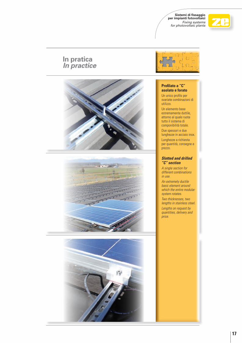
Profilato a “C” asolato e foratoUn unico profilo per svariate combinazioni di utilizzo. Un elemento base estremamente duttile, attorno al quale ruota tutto il sistema di componibilità totale.Due spessori e due lunghezze in acciaio inox. Lunghezze a richiesta per quantità, consegne e prezzo.
slotted and drilled “C” section A single section for different combinations in use. An extremely ductile basic element around which the entire modular system rotates.Two thicknesses, two lengths in stainless steel. Lengths on request by quantities, delivery and price.
18
Sistemi di fissaggio per impianti fotovoltaiciFixing systems for photovoltaic plants
03 Zincatura a caldo per immersione a richiesta / Hot dip galvanization upon request
40 Inox AISI 304 a richiesta / Stainless steel AISI 304 upon request 41 Inox AISI 316L a richiesta / Stainless steel AISI 316L upon request 73 Inox AISI 430 / Stainless steel AISI 430 75 Inox AISI 430 sp. 1,50 mm / Stainless steel AISI 430 1,50 mm thick. 47 Geomet® 321
Rivestimento /Treatment
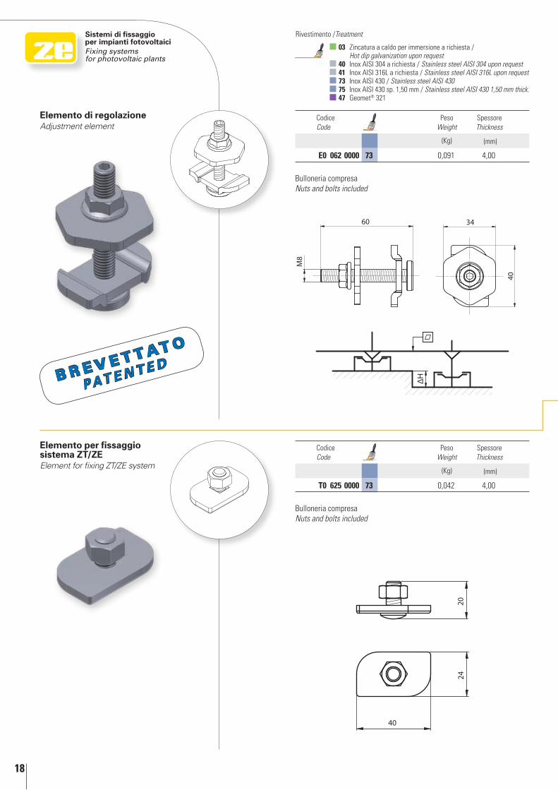
Elemento per fissaggio sistema ZT/ZEElement for fixing ZT/ZE system
Elemento di regolazioneAdjustment element
Codice Code
Peso Weight
Spessore Thickness
(Kg) (mm)
E0 062 0000 73 0,091 4,00
Codice Code
Peso Weight
Spessore Thickness
(Kg) (mm)
T0 625 0000 73 0,042 4,00
Bulloneria compresaNuts and bolts included
Bulloneria compresaNuts and bolts included
B r e v e t tat o
PAT E n T E d
In d
etta
glio
In
det
ail
19
1
2
4
3
1
23
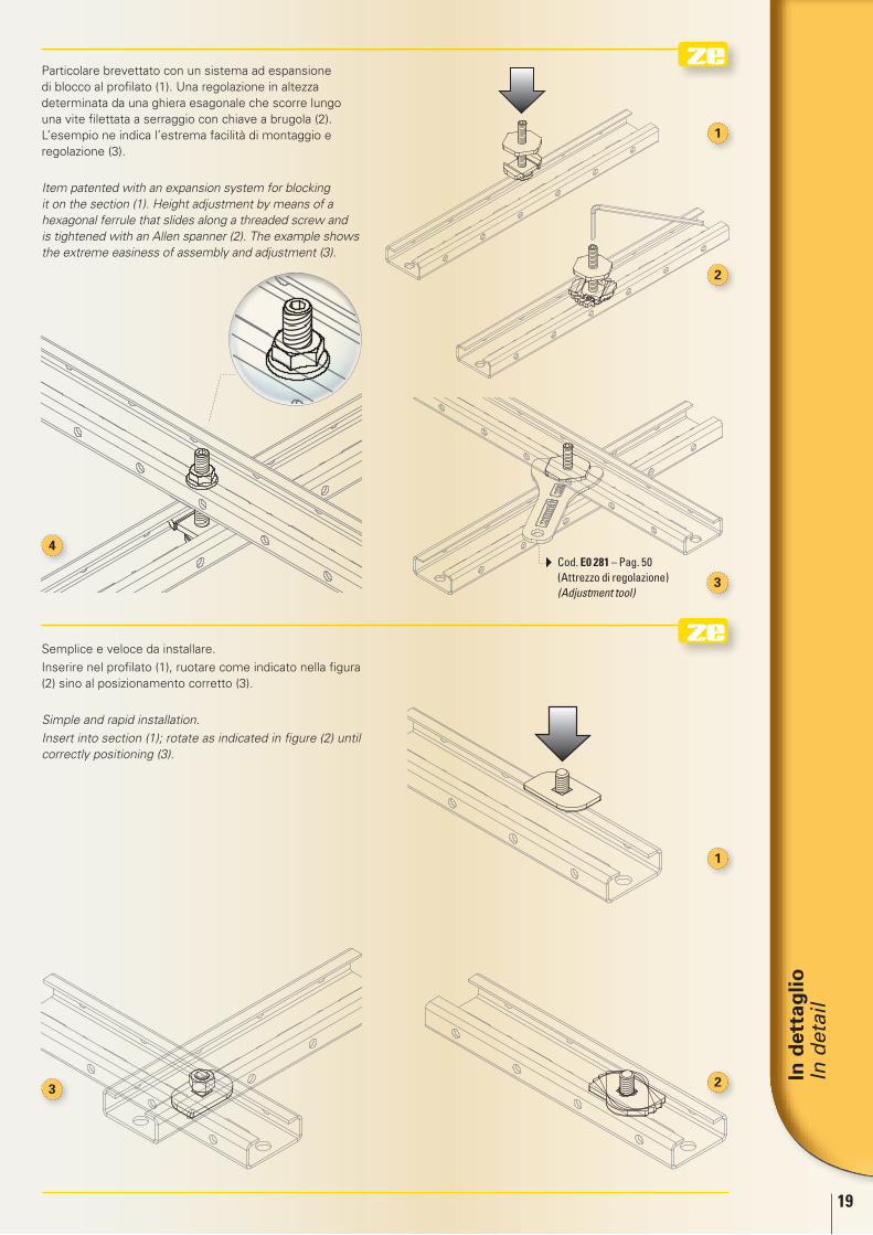
Semplice e veloce da installare.
Inserire nel profilato (1), ruotare come indicato nella figura (2) sino al posizionamento corretto (3).
Simple and rapid installation.
Insert into section (1); rotate as indicated in figure (2) until correctly positioning (3).
Particolare brevettato con un sistema ad espansione di blocco al profilato (1). Una regolazione in altezza determinata da una ghiera esagonale che scorre lungo una vite filettata a serraggio con chiave a brugola (2). L’esempio ne indica l’estrema facilità di montaggio e regolazione (3).
Item patented with an expansion system for blocking it on the section (1). Height adjustment by means of a hexagonal ferrule that slides along a threaded screw and is tightened with an Allen spanner (2). The example shows the extreme easiness of assembly and adjustment (3).
Cod. E0 281 – Pag. 50 (Attrezzo di regolazione) (Adjustment tool)
20
Sistemi di fissaggio per impianti fotovoltaiciFixing systems for photovoltaic plants
03 Zincatura a caldo per immersione a richiesta / Hot dip galvanization upon request
40 Inox AISI 304 a richiesta / Stainless steel AISI 304 upon request 41 Inox AISI 316L a richiesta / Stainless steel AISI 316L upon request 73 Inox AISI 430 / Stainless steel AISI 430 75 Inox AISI 430 sp. 1,50 mm / Stainless steel AISI 430 1,50 mm thick. 47 Geomet® 321
Rivestimento /Treatment
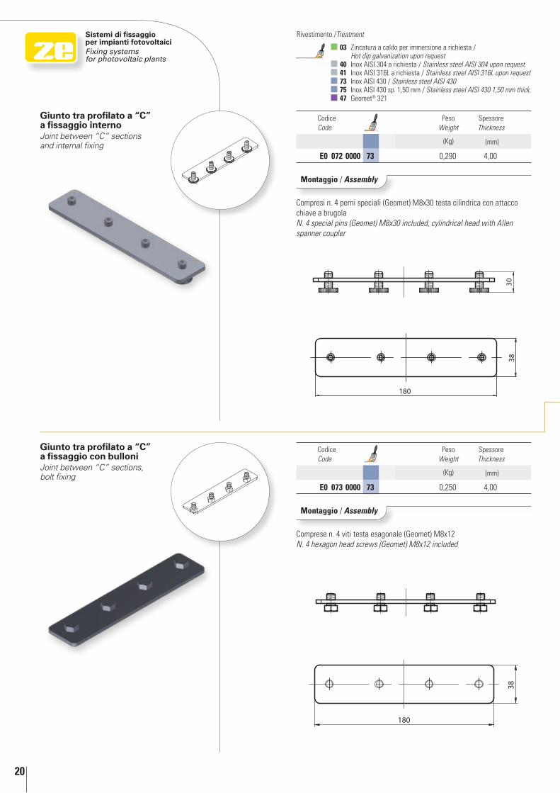
Giunto tra profilato a “C” a fissaggio con bulloniJoint between “C” sections, bolt fixing
Giunto tra profilato a “C” a fissaggio internoJoint between “C” sections and internal fixing
Codice Code
Peso Weight
Spessore Thickness
(Kg) (mm)
E0 072 0000 73 0,290 4,00
Codice Code
Peso Weight
Spessore Thickness
(Kg) (mm)
E0 073 0000 73 0,250 4,00
Montaggio / Assembly
Compresi n. 4 perni speciali (Geomet) M8x30 testa cilindrica con attacco chiave a brugola N. 4 special pins (Geomet) M8x30 included, cylindrical head with Allen spanner coupler
Montaggio / Assembly
Comprese n. 4 viti testa esagonale (Geomet) M8x12N. 4 hexagon head screws (Geomet) M8x12 included
In d
etta
glio
In
det
ail
21
1
1
2
2
3
3
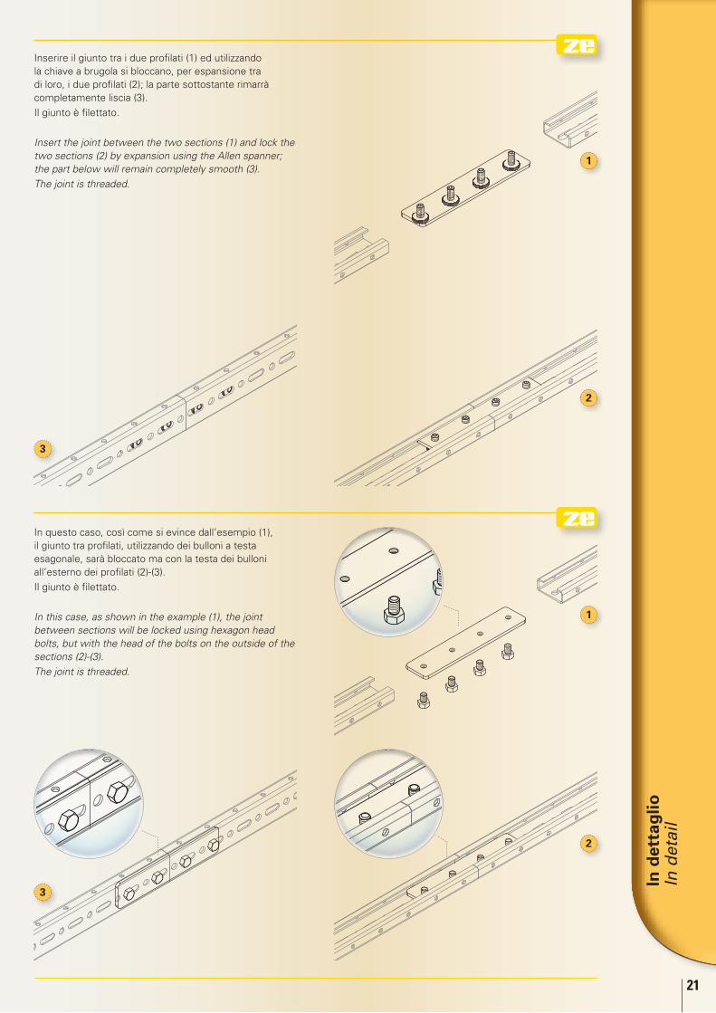
In questo caso, così come si evince dall’esempio (1), il giunto tra profilati, utilizzando dei bulloni a testa esagonale, sarà bloccato ma con la testa dei bulloni all’esterno dei profilati (2)-(3).
Il giunto è filettato.
In this case, as shown in the example (1), the joint between sections will be locked using hexagon head bolts, but with the head of the bolts on the outside of the sections (2)-(3).
The joint is threaded.
Inserire il giunto tra i due profilati (1) ed utilizzando la chiave a brugola si bloccano, per espansione tra di loro, i due profilati (2); la parte sottostante rimarrà completamente liscia (3).
Il giunto è filettato.
Insert the joint between the two sections (1) and lock the two sections (2) by expansion using the Allen spanner; the part below will remain completely smooth (3).
The joint is threaded.
22
Sistemi di fissaggio per impianti fotovoltaiciFixing systems for photovoltaic plants
03 Zincatura a caldo per immersione a richiesta / Hot dip galvanization upon request
40 Inox AISI 304 a richiesta / Stainless steel AISI 304 upon request 41 Inox AISI 316L a richiesta / Stainless steel AISI 316L upon request 73 Inox AISI 430 / Stainless steel AISI 430 75 Inox AISI 430 sp. 1,50 mm / Stainless steel AISI 430 1,50 mm thick. 47 Geomet® 321
Rivestimento /Treatment
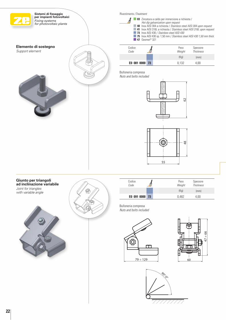
Elemento di sostegnoSupport element
Codice Code
Peso Weight
Spessore Thickness
(Kg) (mm)
E0 081 0000 73 0,132 4,00
Giunto per triangoli ad inclinazione variabileJoint for triangles with variable angle
Codice Code
Peso Weight
Spessore Thickness
(Kg) (mm)
E0 091 0000 73 0,482 4,00
Bulloneria compresaNuts and bolts included
Bulloneria compresaNuts and bolts included
In d
etta
glio
In
det
ail
23
1
2
3
1
2
3
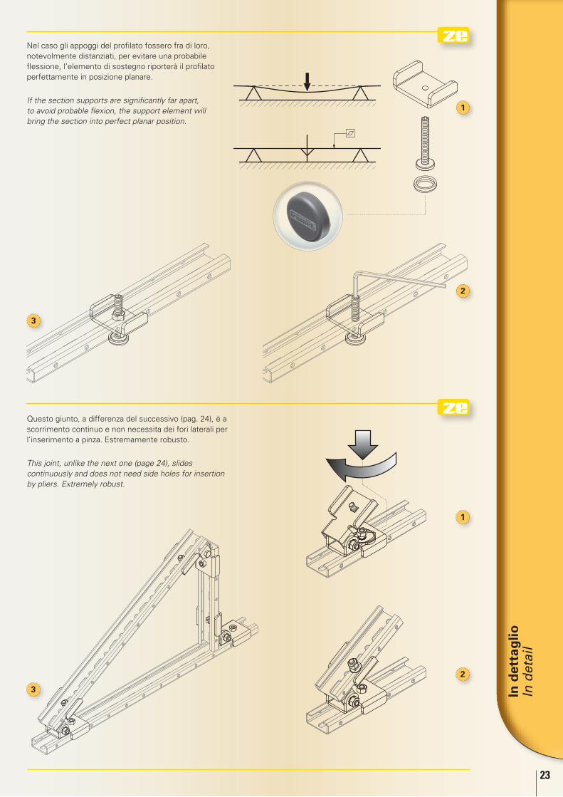
Nel caso gli appoggi del profilato fossero fra di loro, notevolmente distanziati, per evitare una probabile flessione, l’elemento di sostegno riporterà il profilato perfettamente in posizione planare.
If the section supports are significantly far apart, to avoid probable flexion, the support element will bring the section into perfect planar position.
Questo giunto, a differenza del successivo (pag. 24), è a scorrimento continuo e non necessita dei fori laterali per l’inserimento a pinza. Estremamente robusto.
This joint, unlike the next one (page 24), slides continuously and does not need side holes for insertion by pliers. Extremely robust.
24
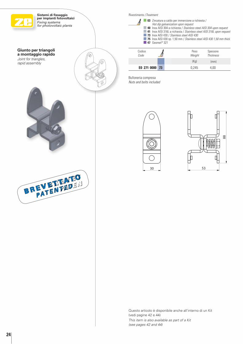
Giunto per triangoli a montaggio rapidoJoint for triangles, rapid assembly
Sistemi di fissaggio per impianti fotovoltaiciFixing systems for photovoltaic plants
03 Zincatura a caldo per immersione a richiesta / Hot dip galvanization upon request
40 Inox AISI 304 a richiesta / Stainless steel AISI 304 upon request 41 Inox AISI 316L a richiesta / Stainless steel AISI 316L upon request 73 Inox AISI 430 / Stainless steel AISI 430 75 Inox AISI 430 sp. 1,50 mm / Stainless steel AISI 430 1,50 mm thick. 47 Geomet® 321
Rivestimento /Treatment
Codice Code
Peso Weight
Spessore Thickness
(Kg) (mm)
E0 271 0000 73 0,245 4,00
Questo articolo è disponibile anche all’interno di un Kit (vedi pagine 42 e 44)
This item is also available as part of a Kit (see pages 42 and 44)
Bulloneria compresaNuts and bolts included
B r e v e t tat o
PAT E n T E d
In d
etta
glio
In
det
ail
25
1
3
2
4
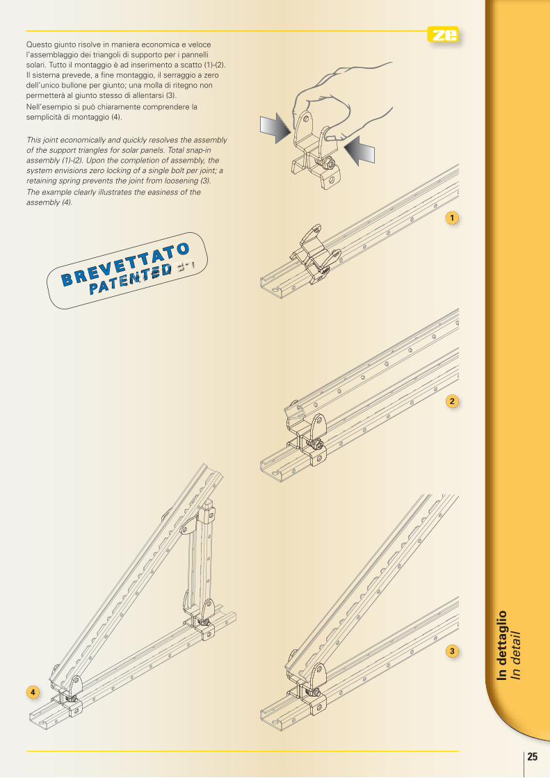
Questo giunto risolve in maniera economica e veloce l’assemblaggio dei triangoli di supporto per i pannelli solari. Tutto il montaggio è ad inserimento a scatto (1)-(2). Il sistema prevede, a fine montaggio, il serraggio a zero dell’unico bullone per giunto; una molla di ritegno non permetterà al giunto stesso di allentarsi (3).
Nell’esempio si può chiaramente comprendere la semplicità di montaggio (4).
This joint economically and quickly resolves the assembly of the support triangles for solar panels. Total snap-in assembly (1)-(2). Upon the completion of assembly, the system envisions zero locking of a single bolt per joint; a retaining spring prevents the joint from loosening (3).
The example clearly illustrates the easiness of the assembly (4).
B r e v e t tat o
PAT E n T E d
26
Sistemi di fissaggio per impianti fotovoltaiciFixing systems for photovoltaic plants
03 Zincatura a caldo per immersione a richiesta / Hot dip galvanization upon request
40 Inox AISI 304 a richiesta / Stainless steel AISI 304 upon request 41 Inox AISI 316L a richiesta / Stainless steel AISI 316L upon request 73 Inox AISI 430 / Stainless steel AISI 430 75 Inox AISI 430 sp. 1,50 mm / Stainless steel AISI 430 1,50 mm thick. 47 Geomet® 321
Rivestimento /Treatment
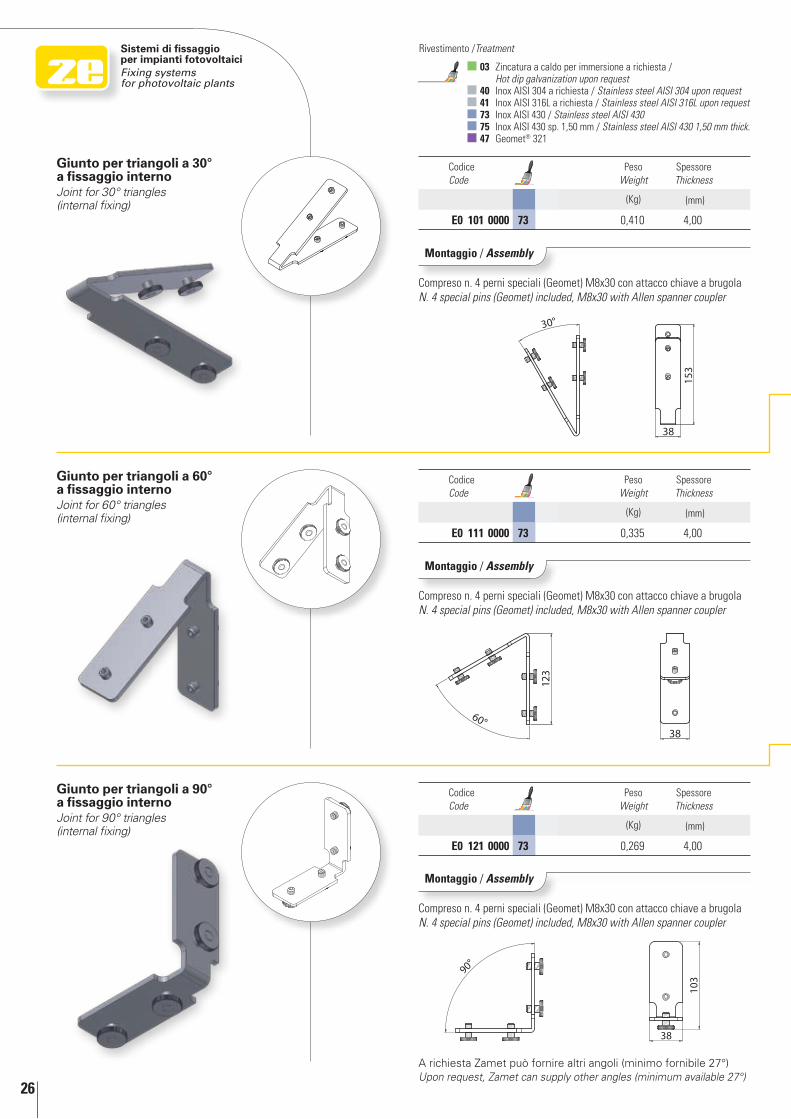
Giunto per triangoli a 90° a fissaggio internoJoint for 90° triangles (internal fixing)
Giunto per triangoli a 60° a fissaggio internoJoint for 60° triangles (internal fixing)
Giunto per triangoli a 30° a fissaggio internoJoint for 30° triangles (internal fixing)
Montaggio / Assembly
Compreso n. 4 perni speciali (Geomet) M8x30 con attacco chiave a brugolaN. 4 special pins (Geomet) included, M8x30 with Allen spanner coupler
Montaggio / Assembly
Compreso n. 4 perni speciali (Geomet) M8x30 con attacco chiave a brugolaN. 4 special pins (Geomet) included, M8x30 with Allen spanner coupler
Montaggio / Assembly
Compreso n. 4 perni speciali (Geomet) M8x30 con attacco chiave a brugolaN. 4 special pins (Geomet) included, M8x30 with Allen spanner coupler
Codice Code
Peso Weight
Spessore Thickness
(Kg) (mm)
E0 101 0000 73 0,410 4,00
Codice Code
Peso Weight
Spessore Thickness
(Kg) (mm)
E0 111 0000 73 0,335 4,00
Codice Code
Peso Weight
Spessore Thickness
(Kg) (mm)
E0 121 0000 73 0,269 4,00
A richiesta Zamet può fornire altri angoli (minimo fornibile 27°)Upon request, Zamet can supply other angles (minimum available 27°)
In d
etta
glio
In
det
ail
27
1
2
3
4
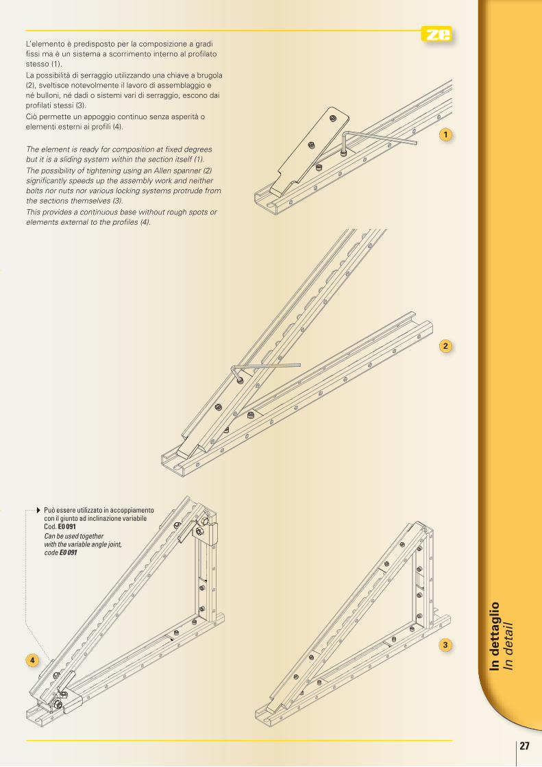
L’elemento è predisposto per la composizione a gradi fissi ma è un sistema a scorrimento interno al profilato stesso (1).
La possibilità di serraggio utilizzando una chiave a brugola (2), sveltisce notevolmente il lavoro di assemblaggio e né bulloni, né dadi o sistemi vari di serraggio, escono dai profilati stessi (3).
Ciò permette un appoggio continuo senza asperità o elementi esterni ai profili (4).
The element is ready for composition at fixed degrees but it is a sliding system within the section itself (1).
The possibility of tightening using an Allen spanner (2) significantly speeds up the assembly work and neither bolts nor nuts nor various locking systems protrude from the sections themselves (3).
This provides a continuous base without rough spots or elements external to the profiles (4).
Può essere utilizzato in accoppiamento con il giunto ad inclinazione variabile Cod. E0 091
Can be used together with the variable angle joint, code E0 091
28
Sistemi di fissaggio per impianti fotovoltaiciFixing systems for photovoltaic plants
03 Zincatura a caldo per immersione a richiesta / Hot dip galvanization upon request
40 Inox AISI 304 a richiesta / Stainless steel AISI 304 upon request 41 Inox AISI 316L a richiesta / Stainless steel AISI 316L upon request 73 Inox AISI 430 / Stainless steel AISI 430 75 Inox AISI 430 sp. 1,50 mm / Stainless steel AISI 430 1,50 mm thick. 47 Geomet® 321
Rivestimento /Treatment
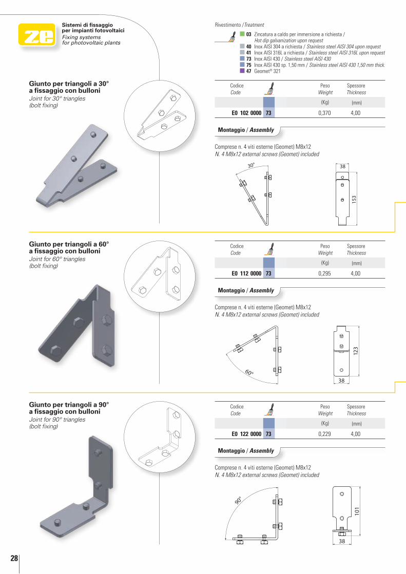
Giunto per triangoli a 90° a fissaggio con bulloniJoint for 90° triangles (bolt fixing)
Giunto per triangoli a 60° a fissaggio con bulloniJoint for 60° triangles (bolt fixing)
Giunto per triangoli a 30° a fissaggio con bulloniJoint for 30° triangles (bolt fixing)
Codice Code
Peso Weight
Spessore Thickness
(Kg) (mm)
E0 102 0000 73 0,370 4,00
Codice Code
Peso Weight
Spessore Thickness
(Kg) (mm)
E0 112 0000 73 0,295 4,00
Codice Code
Peso Weight
Spessore Thickness
(Kg) (mm)
E0 122 0000 73 0,229 4,00
Montaggio / Assembly
Comprese n. 4 viti esterne (Geomet) M8x12N. 4 M8x12 external screws (Geomet) included
Montaggio / Assembly
Comprese n. 4 viti esterne (Geomet) M8x12N. 4 M8x12 external screws (Geomet) included
Montaggio / Assembly
Comprese n. 4 viti esterne (Geomet) M8x12N. 4 M8x12 external screws (Geomet) included
In d
etta
glio
In
det
ail
29
1
2
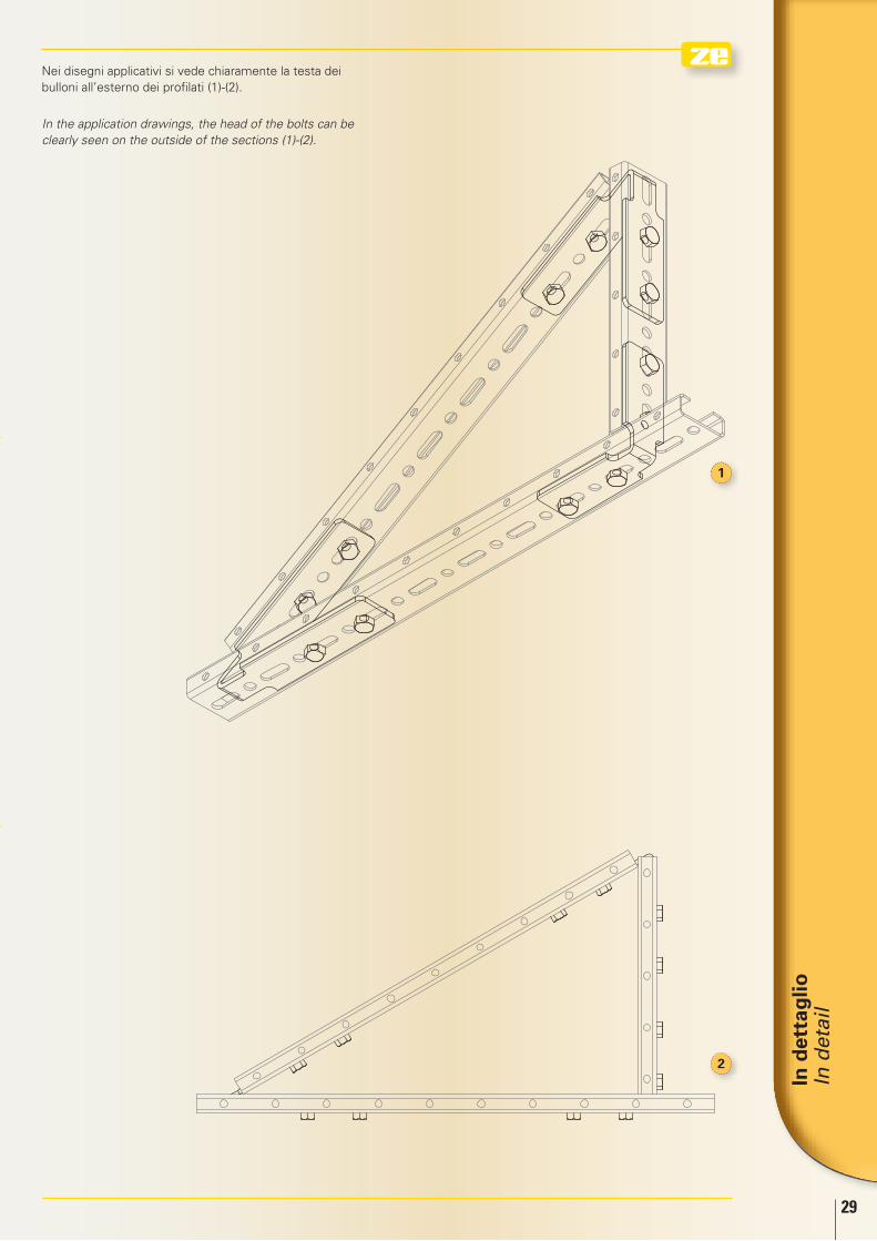
Nei disegni applicativi si vede chiaramente la testa dei bulloni all’esterno dei profilati (1)-(2).
In the application drawings, the head of the bolts can be clearly seen on the outside of the sections (1)-(2).
30
Sistemi di fissaggio per impianti fotovoltaiciFixing systems for photovoltaic plants
03 Zincatura a caldo per immersione a richiesta / Hot dip galvanization upon request
40 Inox AISI 304 a richiesta / Stainless steel AISI 304 upon request 41 Inox AISI 316L a richiesta / Stainless steel AISI 316L upon request 73 Inox AISI 430 / Stainless steel AISI 430 75 Inox AISI 430 sp. 1,50 mm / Stainless steel AISI 430 1,50 mm thick. 47 Geomet® 321
Rivestimento /Treatment
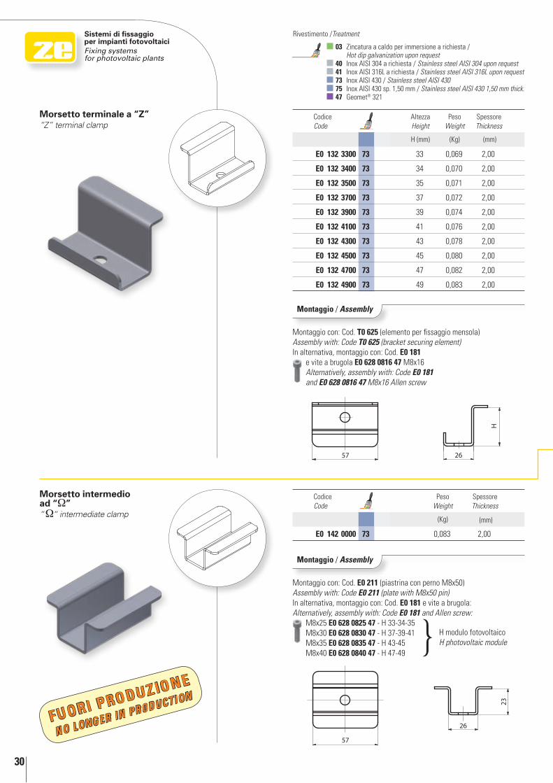
Morsetto intermedio ad “Ω”“Ω“ intermediate clamp
Morsetto terminale a “Z”“Z” terminal clamp
Codice Code
Altezza Height
Peso Weight
Spessore Thickness
H (mm) (Kg) (mm)
E0 132 3300 73 33 0,069 2,00
E0 132 3400 73 34 0,070 2,00
E0 132 3500 73 35 0,071 2,00
E0 132 3700 73 37 0,072 2,00
E0 132 3900 73 39 0,074 2,00
E0 132 4100 73 41 0,076 2,00
E0 132 4300 73 43 0,078 2,00
E0 132 4500 73 45 0,080 2,00
E0 132 4700 73 47 0,082 2,00
E0 132 4900 73 49 0,083 2,00
Codice Code
Peso Weight
Spessore Thickness
(Kg) (mm)
E0 142 0000 73 0,083 2,00
Montaggio / Assembly
Montaggio con: Cod. T0 625 (elemento per fissaggio mensola)Assembly with: Code T0 625 (bracket securing element)In alternativa, montaggio con: Cod. E0 181 e vite a brugola E0 628 0816 47 M8x16 Alternatively, assembly with: Code E0 181 and E0 628 0816 47 M8x16 Allen screw
Montaggio / Assembly
Montaggio con: Cod. E0 211 (piastrina con perno M8x50)Assembly with: Code E0 211 (plate with M8x50 pin) In alternativa, montaggio con: Cod. E0 181 e vite a brugola:Alternatively, assembly with: Code E0 181 and Allen screw: M8x25 E0 628 0825 47 - H 33-34-35 M8x30 E0 628 0830 47 - H 37-39-41 M8x35 E0 628 0835 47 - H 43-45 M8x40 E0 628 0840 47 - H 47-49
H modulo fotovoltaicoH photovoltaic module
FUORI PROdUZIONE
No LoNGER iN pRodUCTioN
In d
etta
glio
In
det
ail
31
1
1
2
2
3
3
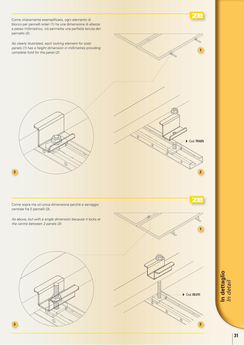
Come chiaramente esemplificato, ogni elemento di blocco per pannelli solari (1) ha una dimensione di altezza a passo millimetrico, ciò permette una perfetta tenuta del pannello (2).
As clearly illustrated, each locking element for solar panels (1) has a height dimension in millimetres providing complete hold for the panel (2).
Come sopra ma un’unica dimensione perché a serraggio centrale fra 2 pannelli (3).
As above, but with a single dimension because it locks at the centre between 2 panels (3).
Cod. T0 625
Cod. E0 211
32
Sistemi di fissaggio per impianti fotovoltaiciFixing systems for photovoltaic plants
03 Zincatura a caldo per immersione a richiesta / Hot dip galvanization upon request
40 Inox AISI 304 a richiesta / Stainless steel AISI 304 upon request 41 Inox AISI 316L a richiesta / Stainless steel AISI 316L upon request 73 Inox AISI 430 / Stainless steel AISI 430 75 Inox AISI 430 sp. 1,50 mm / Stainless steel AISI 430 1,50 mm thick. 47 Geomet® 321
Rivestimento /Treatment
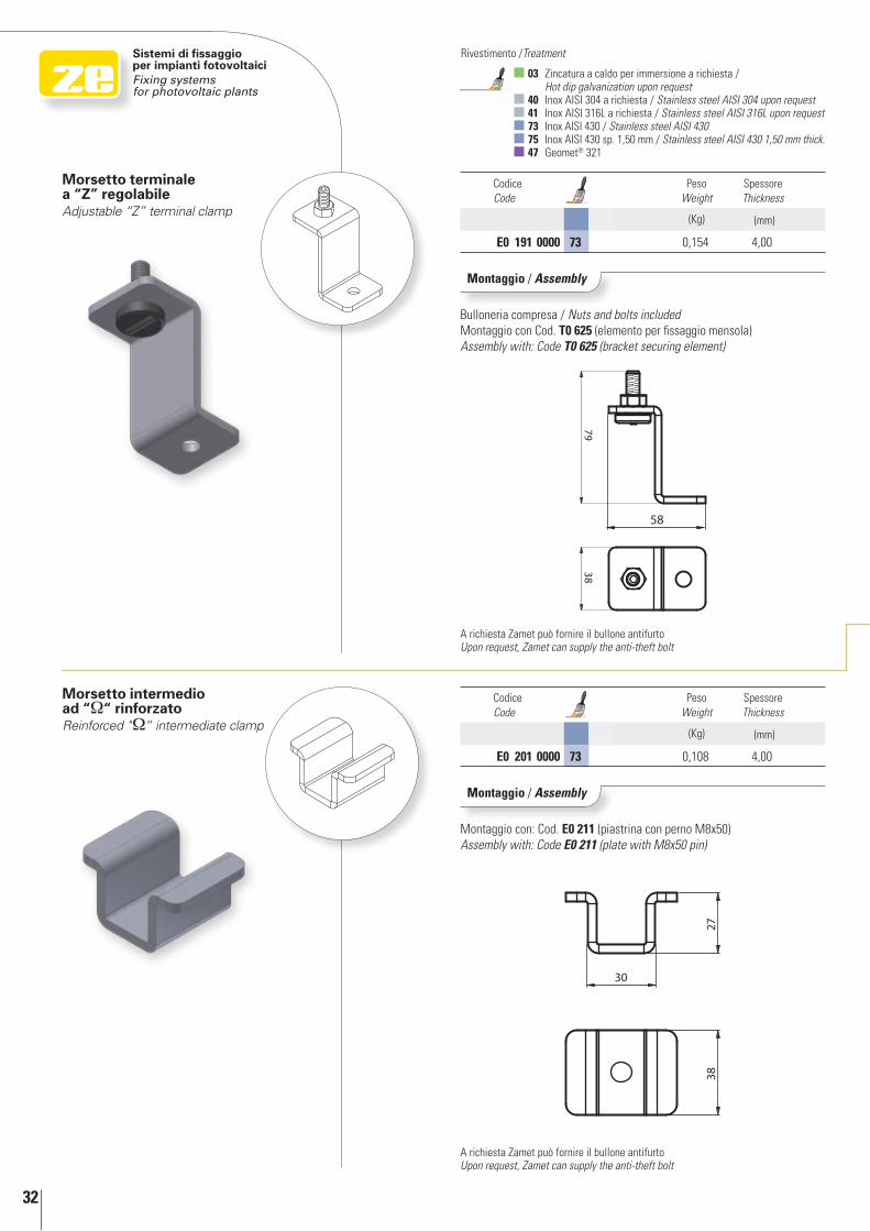
Morsetto intermedio ad “Ω“ rinforzatoReinforced "Ω“ intermediate clamp
Codice Code
Peso Weight
Spessore Thickness
(Kg) (mm)
E0 201 0000 73 0,108 4,00
Morsetto terminale a “Z” regolabileAdjustable “Z” terminal clamp
Codice Code
Peso Weight
Spessore Thickness
(Kg) (mm)
E0 191 0000 73 0,154 4,00
A richiesta Zamet può fornire il bullone antifurto Upon request, Zamet can supply the anti-theft bolt
A richiesta Zamet può fornire il bullone antifurto Upon request, Zamet can supply the anti-theft bolt
Montaggio / Assembly
Bulloneria compresa / Nuts and bolts includedMontaggio con Cod. T0 625 (elemento per fissaggio mensola)Assembly with: Code T0 625 (bracket securing element)
Montaggio / Assembly
Montaggio con: Cod. E0 211 (piastrina con perno M8x50)Assembly with: Code E0 211 (plate with M8x50 pin)
In d
etta
glio
In
det
ail
33
1
2
1
3
24
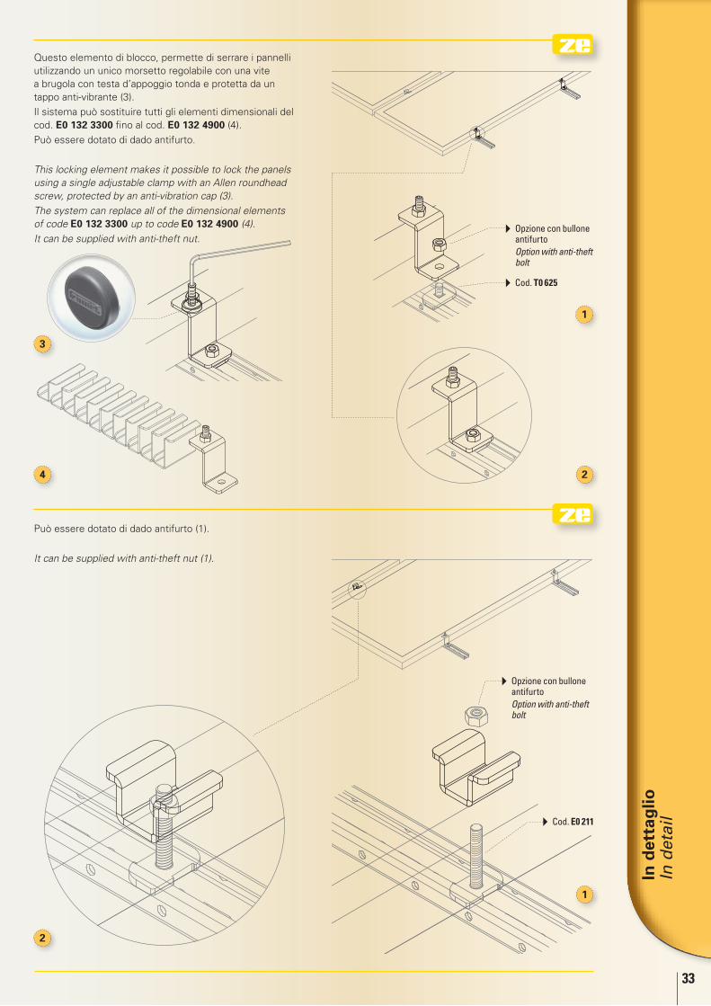
Può essere dotato di dado antifurto (1).
It can be supplied with anti-theft nut (1).
Questo elemento di blocco, permette di serrare i pannelli utilizzando un unico morsetto regolabile con una vite a brugola con testa d’appoggio tonda e protetta da un tappo anti-vibrante (3).
Il sistema può sostituire tutti gli elementi dimensionali del cod. E0 132 3300 fino al cod. E0 132 4900 (4).
Può essere dotato di dado antifurto.
This locking element makes it possible to lock the panels using a single adjustable clamp with an Allen roundhead screw, protected by an anti-vibration cap (3).
The system can replace all of the dimensional elements of code E0 132 3300 up to code E0 132 4900 (4).
It can be supplied with anti-theft nut. Opzione con bullone
antifurto Option with anti-theft
bolt
Opzione con bullone antifurto
Option with anti-theft bolt
Cod. T0 625
Cod. E0 211
34
Sistemi di fissaggio per impianti fotovoltaiciFixing systems for photovoltaic plants
03 Zincatura a caldo per immersione a richiesta / Hot dip galvanization upon request
40 Inox AISI 304 a richiesta / Stainless steel AISI 304 upon request 41 Inox AISI 316L a richiesta / Stainless steel AISI 316L upon request 73 Inox AISI 430 / Stainless steel AISI 430 75 Inox AISI 430 sp. 1,50 mm / Stainless steel AISI 430 1,50 mm thick. 47 Geomet® 321
Rivestimento /Treatment
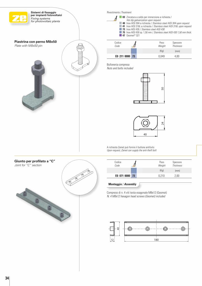
Giunto per profilato a “C”Joint for “C” section
Codice Code
Peso Weight
Spessore Thickness
(Kg) (mm)
E0 071 0000 73 0,210 2,00
Codice Code
Peso Weight
Spessore Thickness
(Kg) (mm)
E0 211 0000 73 0,049 4,00
Piastrina con perno M8x50Plate with M8x50 pin
Montaggio / Assembly
Compreso di n. 4 viti testa esagonale M8x12 (Geomet)N. 4 M8x12 hexagon head screws (Geomet) included
Bulloneria compresaNuts and bolts included
A richiesta Zamet può fornire il bullone antifurto Upon request, Zamet can supply the anti-theft bolt
In d
etta
glio
In
det
ail
35
3
1
2
3
1
2
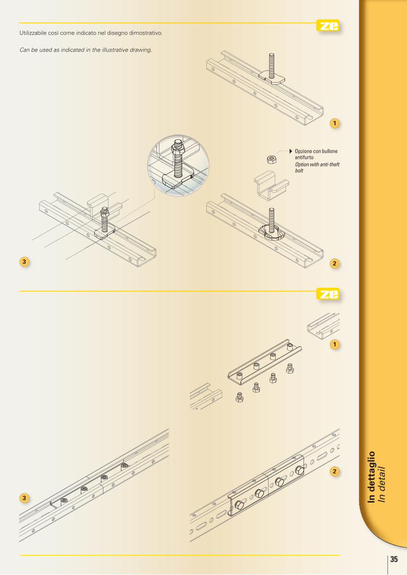
Utilizzabile così come indicato nel disegno dimostrativo.
Can be used as indicated in the illustrative drawing.
Opzione con bullone antifurto
Option with anti-theft bolt
36
Sistemi di fissaggio per impianti fotovoltaiciFixing systems for photovoltaic plants
03 Zincatura a caldo per immersione a richiesta / Hot dip galvanization upon request
40 Inox AISI 304 a richiesta / Stainless steel AISI 304 upon request 41 Inox AISI 316L a richiesta / Stainless steel AISI 316L upon request 73 Inox AISI 430 / Stainless steel AISI 430 75 Inox AISI 430 sp. 1,50 mm / Stainless steel AISI 430 1,50 mm thick. 47 Geomet® 321
Rivestimento /Treatment
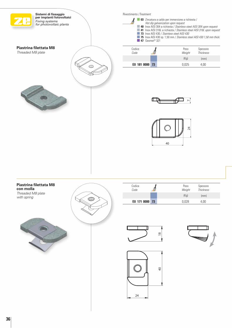
Piastrina filettata M8Threaded M8 plate
Piastrina filettata M8 con mollaThreaded M8 plate with spring
Codice Code
Peso Weight
Spessore Thickness
(Kg) (mm)
E0 171 0000 73 0,028 4,00
Codice Code
Peso Weight
Spessore Thickness
(Kg) (mm)
E0 181 0000 73 0,025 4,00
In d
etta
glio
In
det
ail
37
2
3
1
3
1
2
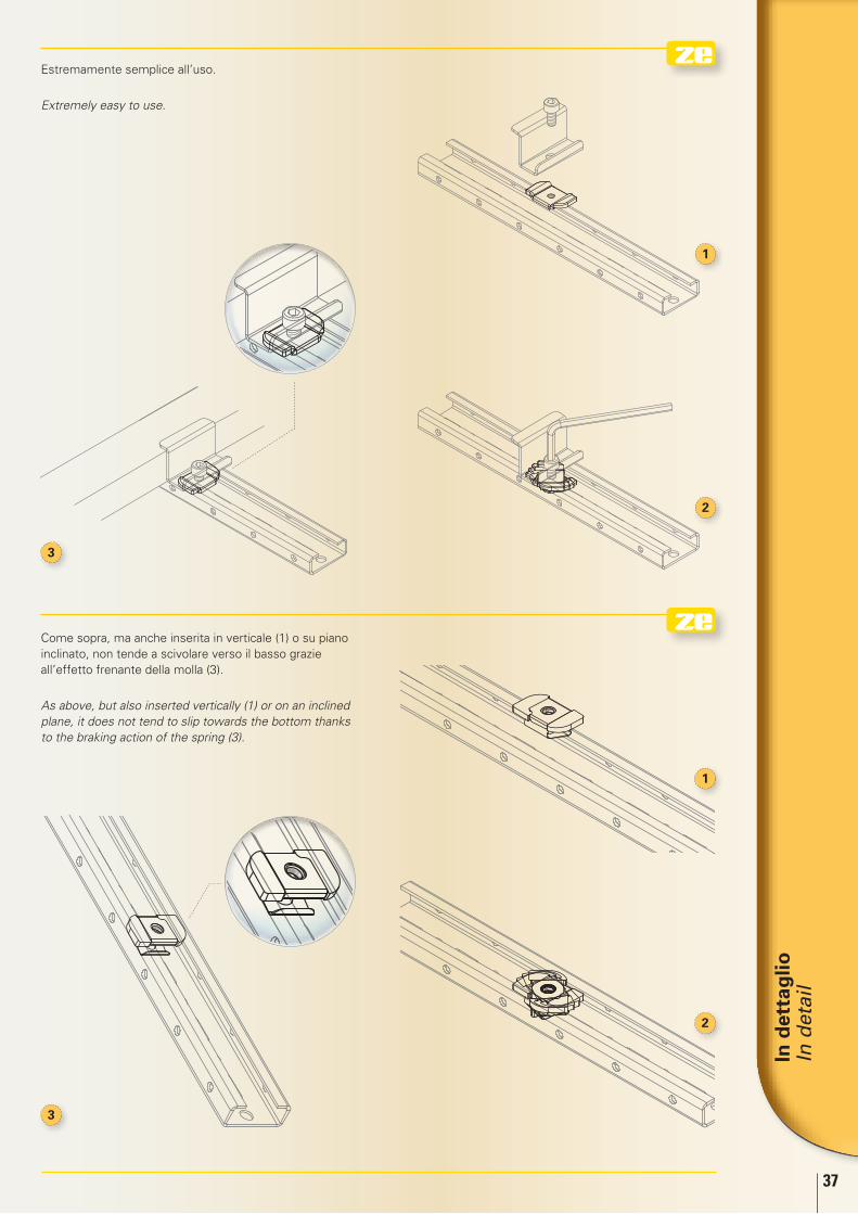
Come sopra, ma anche inserita in verticale (1) o su piano inclinato, non tende a scivolare verso il basso grazie all’effetto frenante della molla (3).
As above, but also inserted vertically (1) or on an inclined plane, it does not tend to slip towards the bottom thanks to the braking action of the spring (3).
Estremamente semplice all’uso.
Extremely easy to use.
38
Sistemi di fissaggio per impianti fotovoltaiciFixing systems for photovoltaic plants
03 Zincatura a caldo per immersione a richiesta / Hot dip galvanization upon request
40 Inox AISI 304 a richiesta / Stainless steel AISI 304 upon request 41 Inox AISI 316L a richiesta / Stainless steel AISI 316L upon request 73 Inox AISI 430 / Stainless steel AISI 430 75 Inox AISI 430 sp. 1,50 mm / Stainless steel AISI 430 1,50 mm thick. 47 Geomet® 321
Rivestimento /Treatment
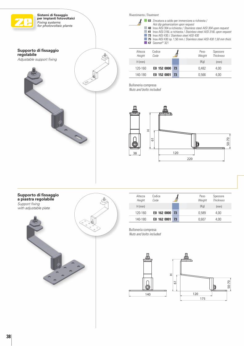
Supporto di fissaggio a piastra regolabileSupport fixing with adjustable plate
Supporto di fissaggio regolabileAdjustable support fixing
Altezza Height
Codice Code
Peso Weight
Spessore Thickness
H (mm) (Kg) (mm)
120-160 E0 152 0000 73 0,482 4,00
140-180 E0 152 0001 73 0,566 4,00
Altezza Height
Codice Code
Peso Weight
Spessore Thickness
H (mm) (Kg) (mm)
120-160 E0 162 0000 73 0,589 4,00
140-180 E0 162 0001 73 0,607 4,00
Bulloneria compresaNuts and bolts included
Bulloneria compresaNuts and bolts included
In d
etta
glio
In
det
ail
39
3
1
2
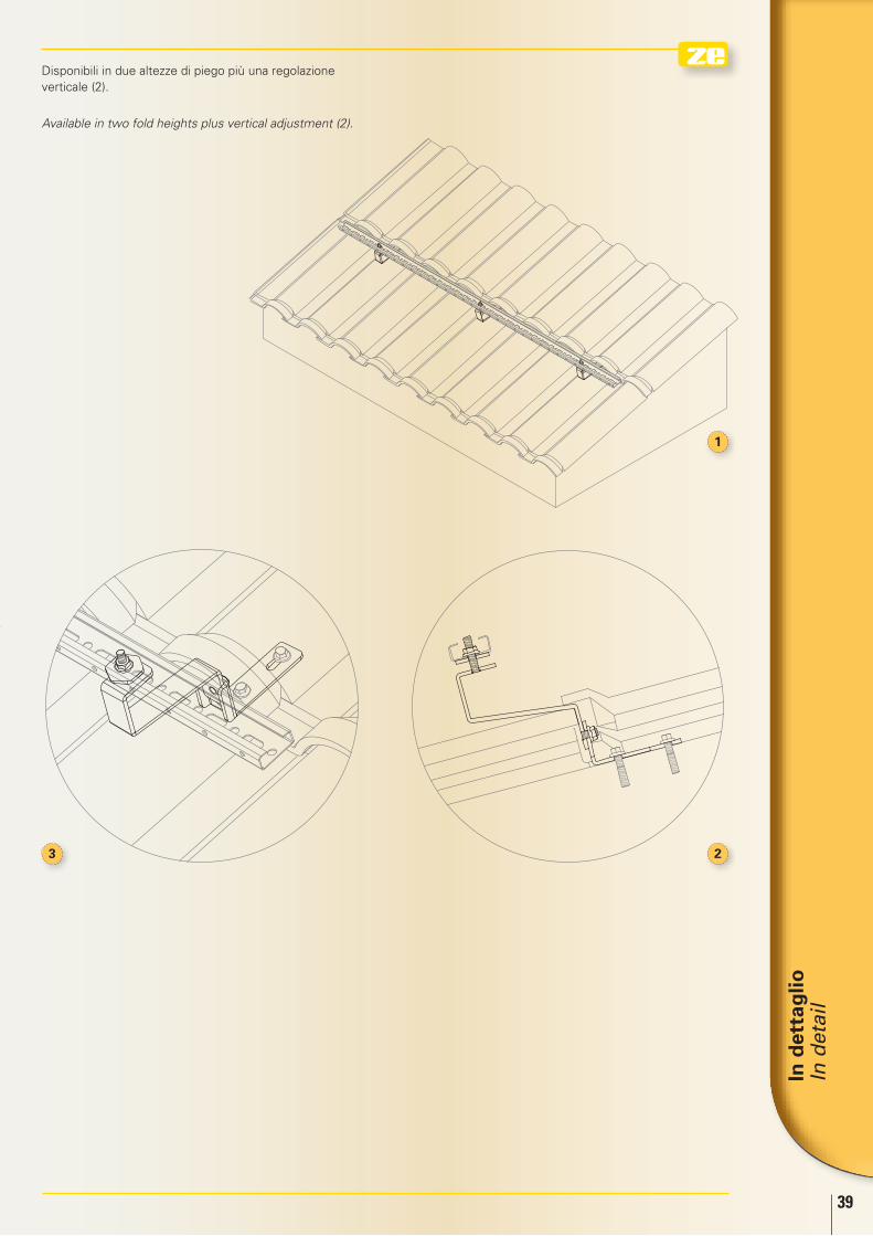
Disponibili in due altezze di piego più una regolazione verticale (2).
Available in two fold heights plus vertical adjustment (2).
40
Sistemi di fissaggio per impianti fotovoltaiciFixing systems for photovoltaic plants
03 Zincatura a caldo per immersione a richiesta / Hot dip galvanization upon request
40 Inox AISI 304 a richiesta / Stainless steel AISI 304 upon request 41 Inox AISI 316L a richiesta / Stainless steel AISI 316L upon request 73 Inox AISI 430 / Stainless steel AISI 430 75 Inox AISI 430 sp. 1,50 mm / Stainless steel AISI 430 1,50 mm thick. 47 Geomet® 321
Rivestimento /Treatment
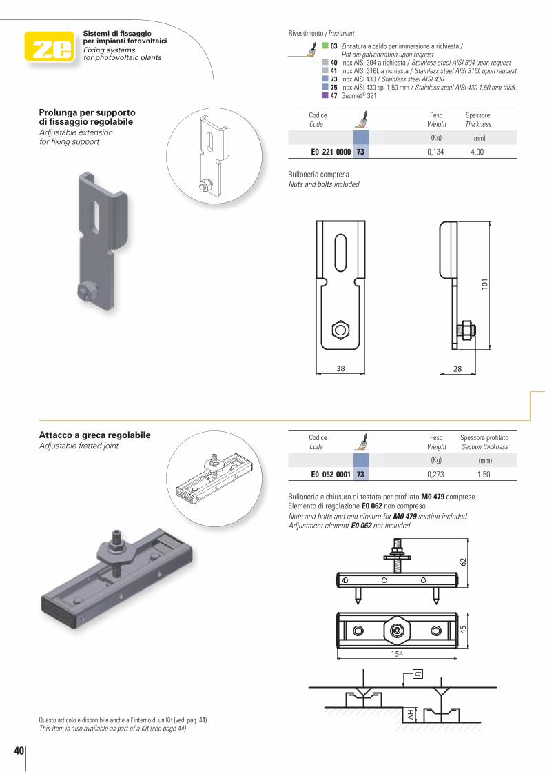
Attacco a greca regolabileAdjustable fretted joint
Codice Code
Peso Weight
Spessore profilato Section thickness
(Kg) (mm)
E0 052 0001 73 0,273 1,50
Questo articolo è disponibile anche all’interno di un Kit (vedi pag. 44)This item is also available as part of a Kit (see page 44)
Prolunga per supporto di fissaggio regolabileAdjustable extension for fixing support
Codice Code
Peso Weight
Spessore Thickness
(Kg) (mm)
E0 221 0000 73 0,134 4,00
Bulloneria e chiusura di testata per profilato M0 479 comprese. Elemento di regolazione E0 062 non compresoNuts and bolts and end closure for M0 479 section included. Adjustment element E0 062 not included
Bulloneria compresaNuts and bolts included
In d
etta
glio
In
det
ail
41
2
1
5 4 3
1
23
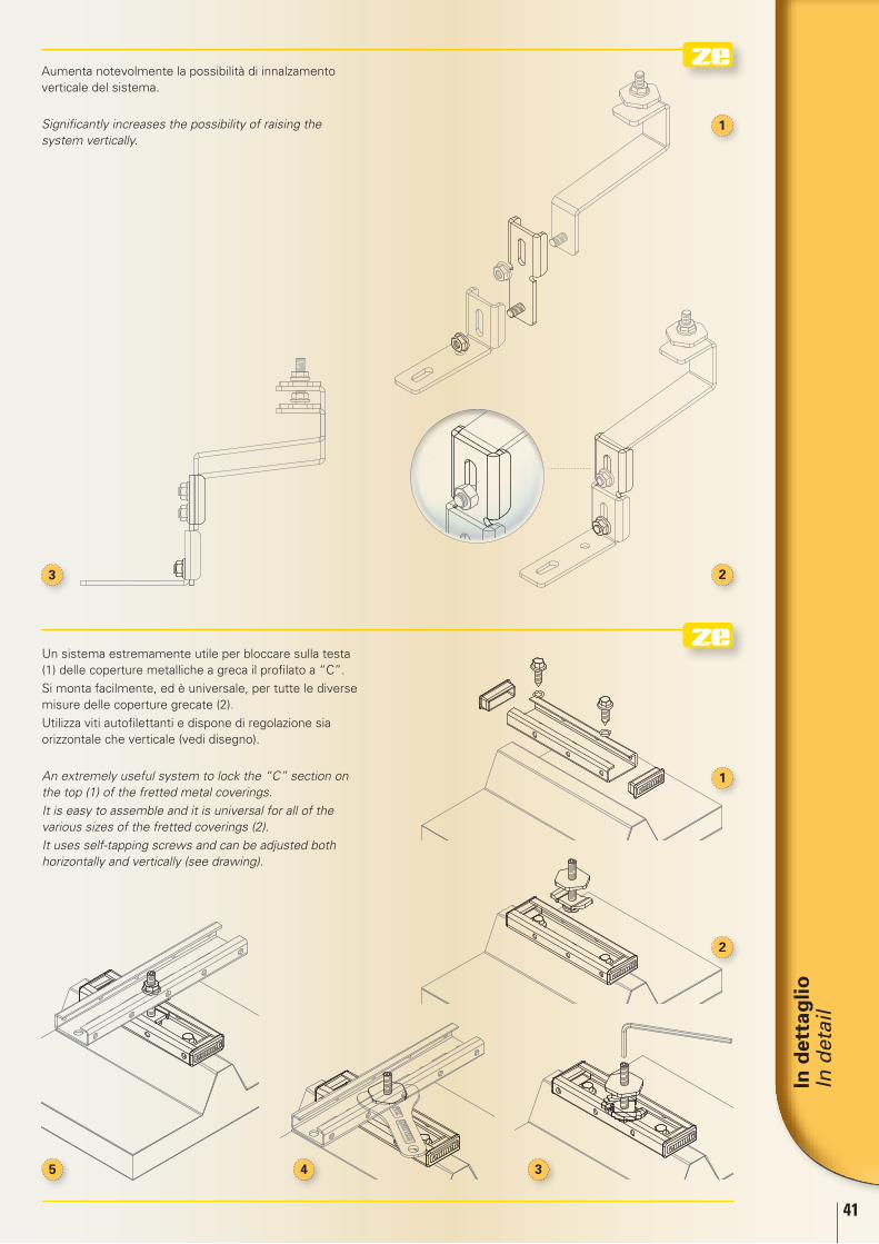
Aumenta notevolmente la possibilità di innalzamento verticale del sistema.
Significantly increases the possibility of raising the system vertically.
Un sistema estremamente utile per bloccare sulla testa (1) delle coperture metalliche a greca il profilato a “C”.
Si monta facilmente, ed è universale, per tutte le diverse misure delle coperture grecate (2).
Utilizza viti autofilettanti e dispone di regolazione sia orizzontale che verticale (vedi disegno).
An extremely useful system to lock the “C” section on the top (1) of the fretted metal coverings.
It is easy to assemble and it is universal for all of the various sizes of the fretted coverings (2).
It uses self-tapping screws and can be adjusted both horizontally and vertically (see drawing).
42
Sistemi di fissaggio per impianti fotovoltaiciFixing systems for photovoltaic plants
03 Zincatura a caldo per immersione a richiesta / Hot dip galvanization upon request
40 Inox AISI 304 a richiesta / Stainless steel AISI 304 upon request 41 Inox AISI 316L a richiesta / Stainless steel AISI 316L upon request 73 Inox AISI 430 / Stainless steel AISI 430 75 Inox AISI 430 sp. 1,50 mm / Stainless steel AISI 430 1,50 mm thick. 47 Geomet® 321
Rivestimento /Treatment
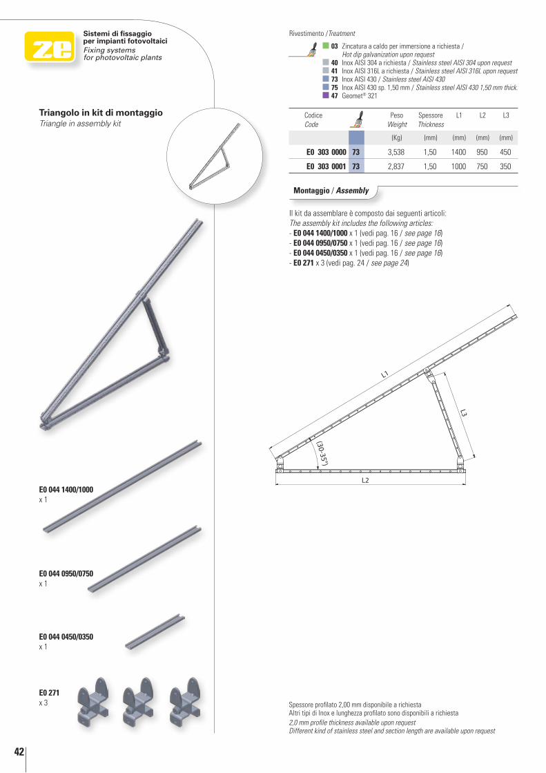
Triangolo in kit di montaggioTriangle in assembly kit
Codice Code
Peso Weight
Spessore Thickness
L1 L2 L3
(Kg) (mm) (mm) (mm) (mm)
E0 303 0000 73 3,538 1,50 1400 950 450
E0 303 0001 73 2,837 1,50 1000 750 350
Montaggio / Assembly
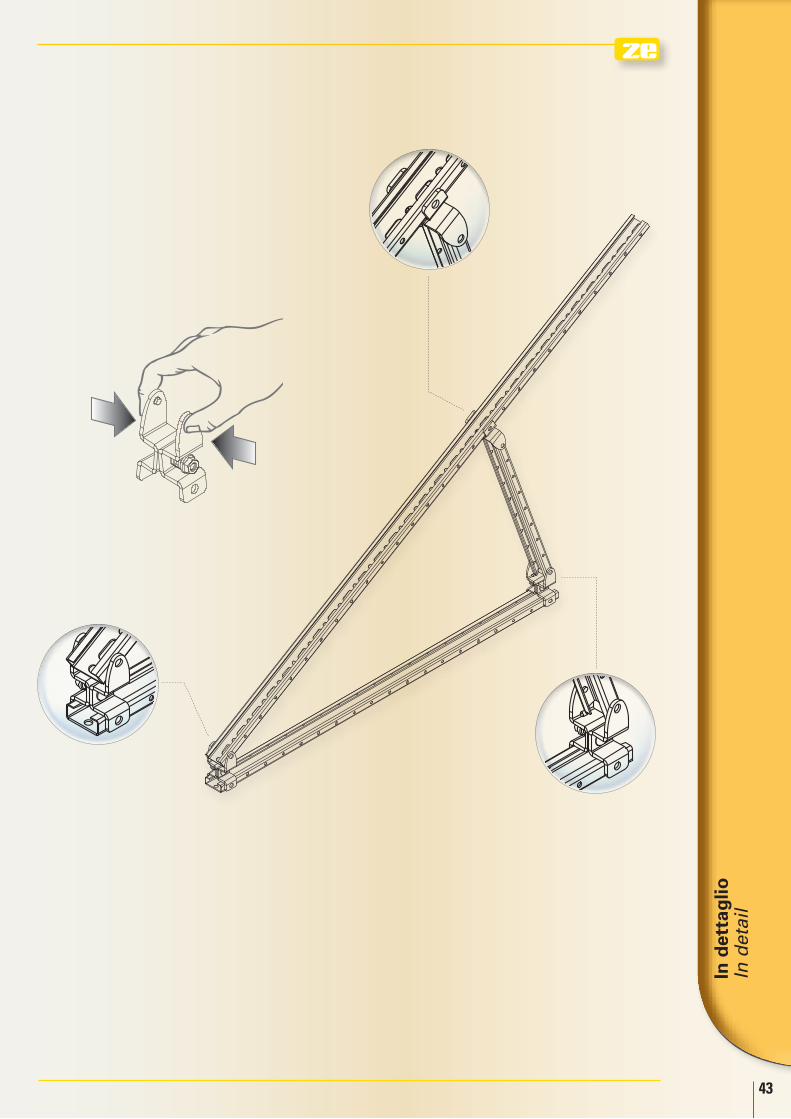
Il kit da assemblare è composto dai seguenti articoli:The assembly kit includes the following articles:- E0 044 1400/1000 x 1 (vedi pag. 16 / see page 16)- E0 044 0950/0750 x 1 (vedi pag. 16 / see page 16)- E0 044 0450/0350 x 1 (vedi pag. 16 / see page 16)- E0 271 x 3 (vedi pag. 24 / see page 24)
Spessore profilato 2,00 mm disponibile a richiestaAltri tipi di Inox e lunghezza profilato sono disponibili a richiesta2,0 mm profile thickness available upon requestDifferent kind of stainless steel and section length are available upon request
E0 044 1400/1000 x 1
E0 271 x 3
E0 044 0450/0350 x 1
E0 044 0950/0750 x 1
In d
etta
glio
In
det
ail
43
44
Sistemi di fissaggio per impianti fotovoltaiciFixing systems for photovoltaic plants
03 Zincatura a caldo per immersione a richiesta / Hot dip galvanization upon request
40 Inox AISI 304 a richiesta / Stainless steel AISI 304 upon request 41 Inox AISI 316L a richiesta / Stainless steel AISI 316L upon request 73 Inox AISI 430 / Stainless steel AISI 430 75 Inox AISI 430 sp. 1,50 mm / Stainless steel AISI 430 1,50 mm thick. 47 Geomet® 321
Rivestimento /Treatment
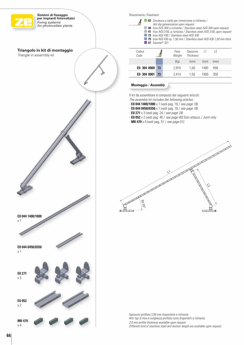
Triangolo in kit di montaggioTriangle in assembly kit
Codice Code
Peso Weight
Spessore Thickness
L1 L2
(Kg) (mm) (mm) (mm)
E0 304 0000 73 2,915 1,50 1400 450
E0 304 0001 73 2,414 1,50 1000 350
Montaggio / Assembly
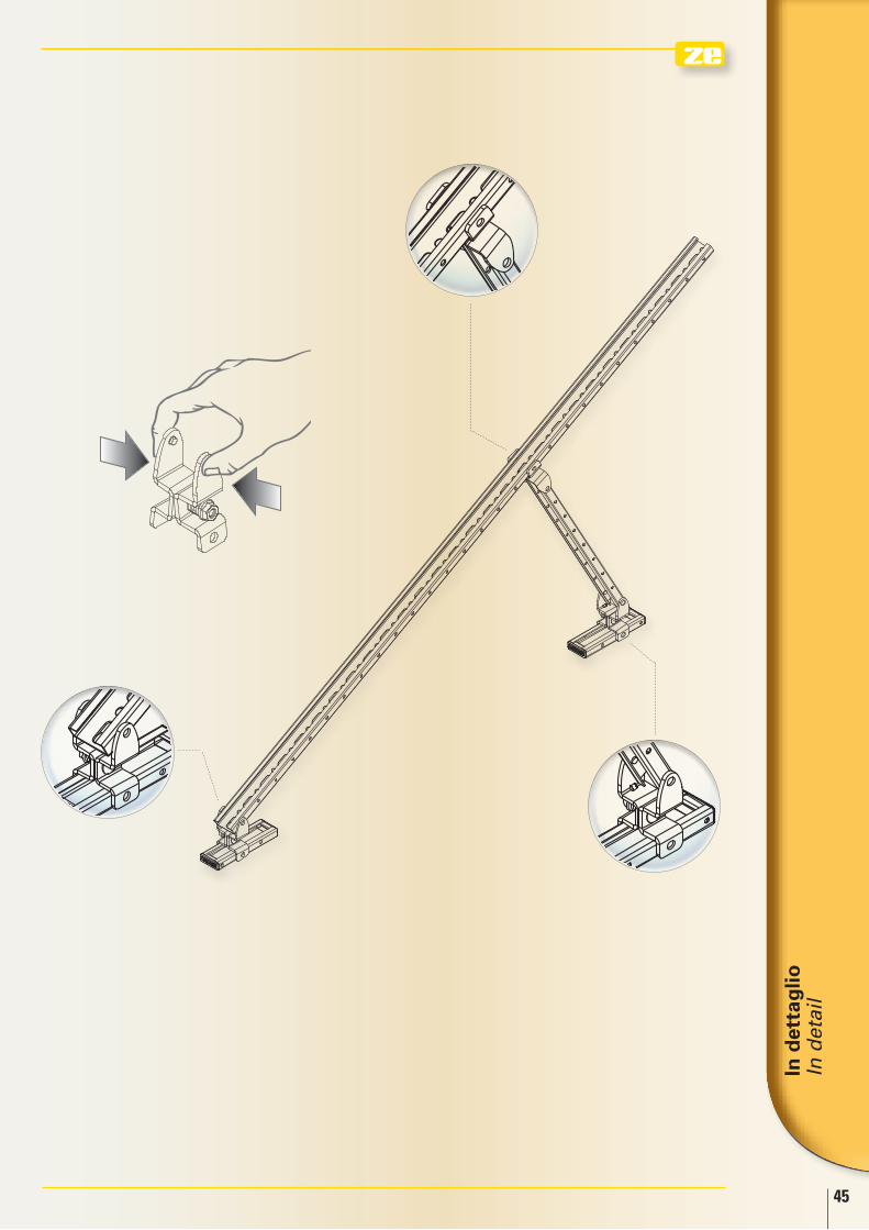
Il kit da assemblare è composto dai seguenti articoli:The assembly kit includes the following articles:- E0 044 1400/1000 x 1 (vedi pag. 16 / see page 16)- E0 044 0450/0350 x 1 (vedi pag. 16 / see page 16)- E0 271 x 3 (vedi pag. 24 / see page 24)- E0 052 x 2 (vedi pag. 40 / see page 40) Solo attacco / Joint only- M0 479 x 4 (vedi pag. 51 / see page 51)
Spessore profilato 2,00 mm disponibile a richiestaAltri tipi di Inox e lunghezza profilato sono disponibili a richiesta2,0 mm profile thickness available upon requestDifferent kind of stainless steel and section length are available upon request
E0 044 1400/1000 x 1
E0 271 x 3
E0 044 0450/0350 x 1
M0 479 x 4
E0 052 x 2
In d
etta
glio
In
det
ail
45
46
L
Sistemi di fissaggio per impianti fotovoltaiciFixing systems for photovoltaic plants
03 Zincatura a caldo per immersione a richiesta / Hot dip galvanization upon request
40 Inox AISI 304 a richiesta / Stainless steel AISI 304 upon request 41 Inox AISI 316L a richiesta / Stainless steel AISI 316L upon request 73 Inox AISI 430 / Stainless steel AISI 430 75 Inox AISI 430 sp. 1,50 mm / Stainless steel AISI 430 1,50 mm thick. 47 Geomet® 321
Rivestimento /Treatment
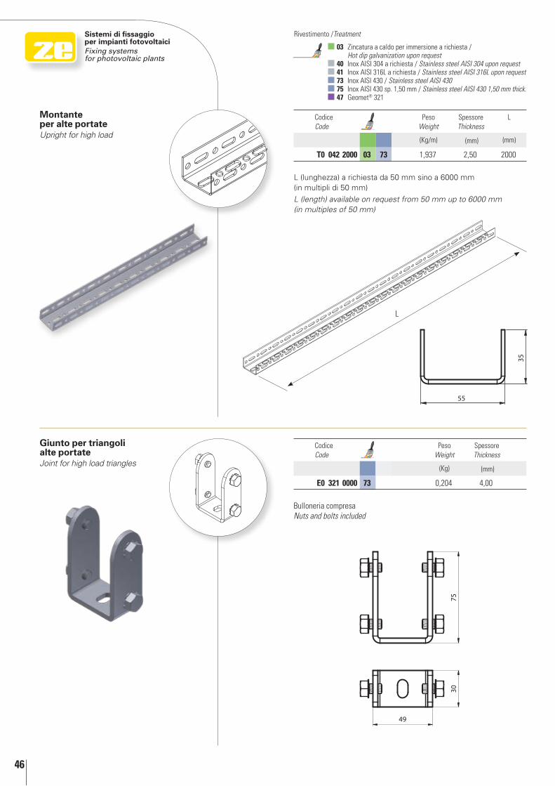
Montante per alte portateUpright for high load
Giunto per triangoli alte portateJoint for high load triangles
Codice Code
Peso Weight
Spessore Thickness
L
(Kg/m) (mm) (mm)
T0 042 2000 03 73 1,937 2,50 2000
Codice Code
Peso Weight
Spessore Thickness
(Kg) (mm)
E0 321 0000 73 0,204 4,00
Bulloneria compresaNuts and bolts included
L (lunghezza) a richiesta da 50 mm sino a 6000 mm (in multipli di 50 mm)
L (length) available on request from 50 mm up to 6000 mm (in multiples of 50 mm)
In d
etta
glio
In
det
ail
47
2
3
1
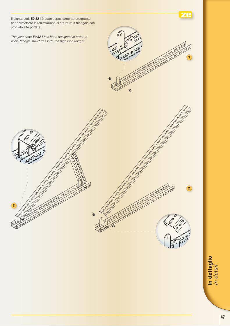
Il giunto cod. E0 321 è stato appositamente progettato per permettere la realizzazione di strutture a triangolo con profilato alte portate.
The joint code E0 321 has been designed in order to allow triangle structures with the high load upright.
48
Sistemi di fissaggio per impianti fotovoltaiciFixing systems for photovoltaic plants
01 Zincato Sendzimir / Sendzimir galvanized 03 Zincatura a caldo per immersione a richiesta /
Hot dip galvanization upon request 40 Inox AISI 304 a richiesta / Stainless steel AISI 304 upon request 41 Inox AISI 316L a richiesta / Stainless steel AISI 316L upon request 73 Inox AISI 430 / Stainless steel AISI 430 75 Inox AISI 430 sp. 1,50 mm / Stainless steel AISI 430 1,50 mm thick.
Rivestimento /Treatment
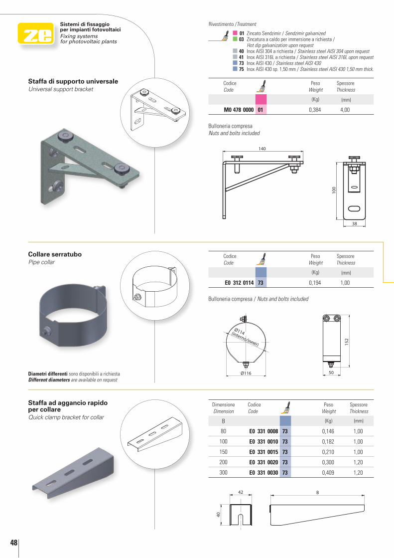
Collare serratuboPipe collar
Staffa ad aggancio rapido per collareQuick clamp bracket for collar
Dimensione Dimension
Codice Code
Peso Weight
Spessore Thickness
B (Kg) (mm)
80 E0 331 0008 73 0,146 1,00
100 E0 331 0010 73 0,182 1,00
150 E0 331 0015 73 0,210 1,00
200 E0 331 0020 73 0,300 1,20
300 E0 331 0030 73 0,409 1,20
diametri differenti sono disponibili a richiestadifferent diameters are available on request
Staffa di supporto universaleUniversal support bracket
Codice Code
Peso Weight
Spessore Thickness
(Kg) (mm)
M0 478 0000 01 0,384 4,00
Codice Code
Peso Weight
Spessore Thickness
(Kg) (mm)
E0 312 0114 73 0,194 1,00
Bulloneria compresaNuts and bolts included
Bulloneria compresa / Nuts and bolts included
In d
etta
glio
In
det
ail
49
1
234
1
3
2
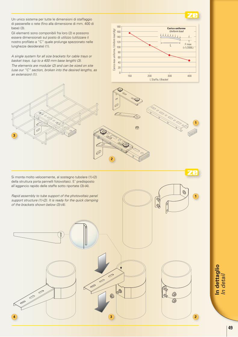
Si monta molto velocemente, al sostegno tubolare (1)-(2) della struttura porta pannelli fotovoltaici. E’ predisposto all’aggancio rapido delle staffe sotto riportate (3)-(4).
Rapid assembly to tube support of the photovoltaic panel support structure (1)-(2). It is ready for the quick clamping of the brackets shown below (3)-(4).
Un unico sistema per tutte le dimensioni di staffaggio di passerelle o rete (fino alla dimensione di mm. 400 di base) (3).
Gli elementi sono componibili fra loro (2) e possono essere dimensionati sul posto di utilizzo (utilizzare il nostro profilato a “C” quale prolunga spezzonato nelle lunghezze desiderate) (1).
A single system for all size brackets for cable trays or basket trays. (up to a 400 mm base length) (3).
The elements are modular (2) and can be sized on site (use our “C” section, broken into the desired lengths, as an extension) (1).
Caric
o m
ax u
nifo
rme
/ Uni
form
load
(Kg)
L Staffa / Bracket
180
160
140
120
100
80
60
40
20
0
L F max(<1/200L)
Carico uniforme Uniform load
150 200 300 400
50
Sistemi di fissaggio per impianti fotovoltaiciFixing systems for photovoltaic plants
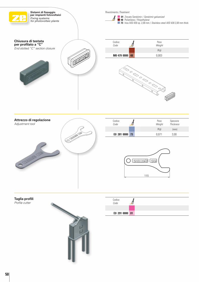
Attrezzo di regolazioneAdjustment tool
Taglia profiliProfile cutter
Codice Code
Peso Weight
(Kg)
M0 479 0000 48 0,003
Codice Code
Peso Weight
Spessore Thickness
(Kg) (mm)
E0 281 0000 73 0,071 3,00
Codice Code
E0 291 0000 01
01 Zincato Sendzimir / Sendzimir galvanized 48 Polietilene / Polyethylene 73 Inox AISI 430 sp. 2,00 mm / Stainless steel AISI 430 2,00 mm thick.
Rivestimento /Treatment
Chiusura di testata per profilato a “C”End slotted “C” section closure
51
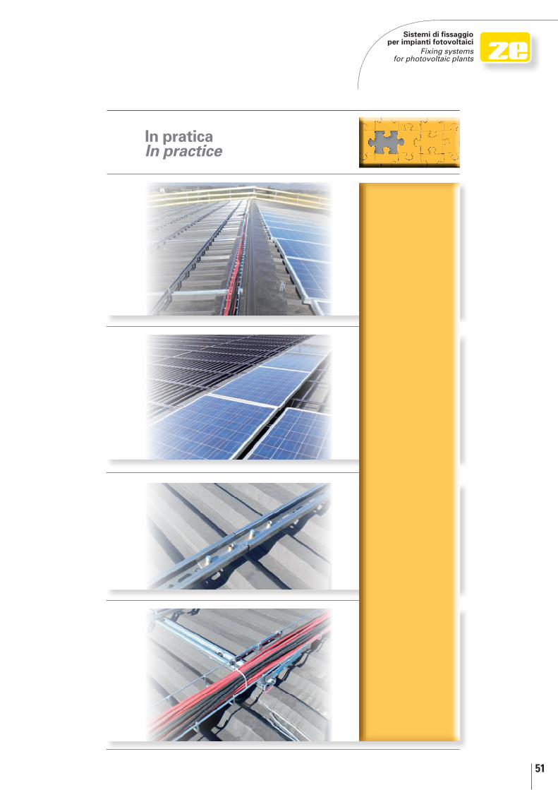
Sistemi di fissaggio per impianti fotovoltaici
Fixing systems for photovoltaic plants
In praticaIn practice
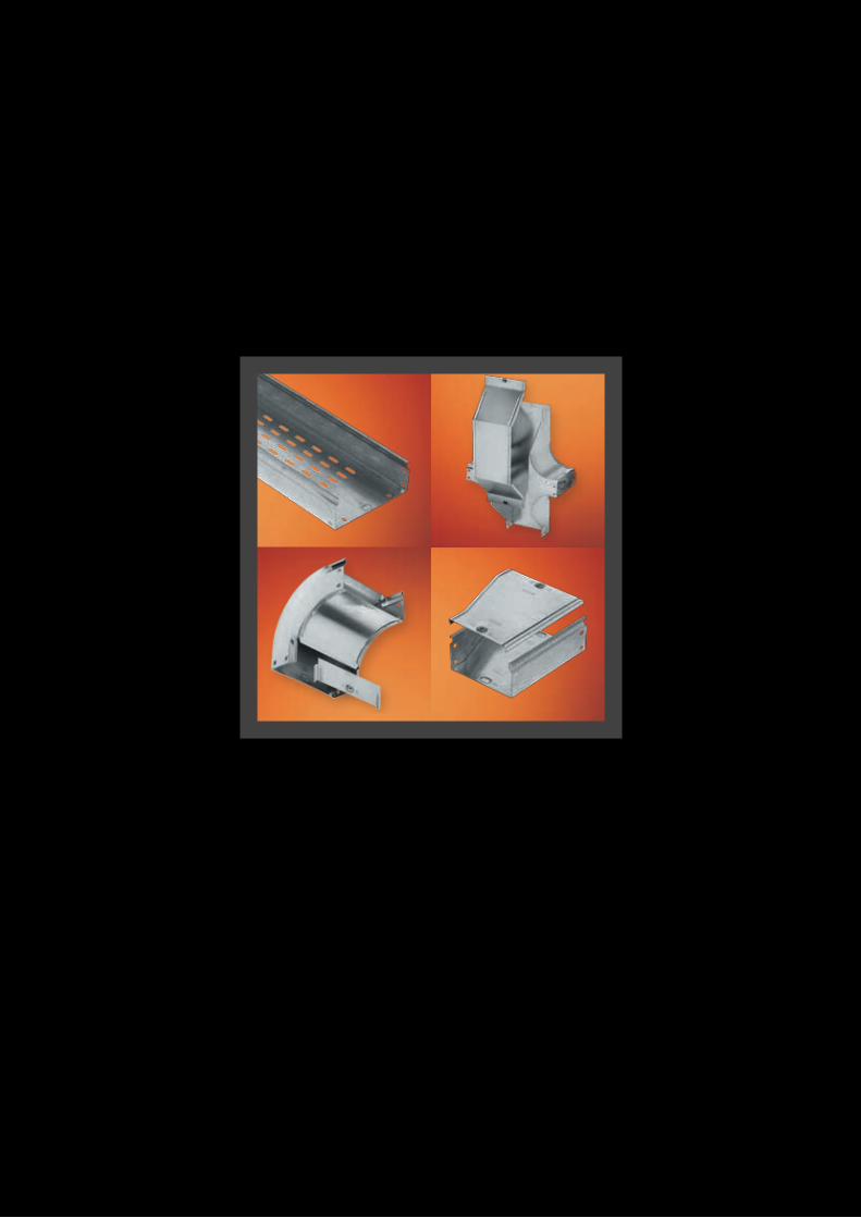
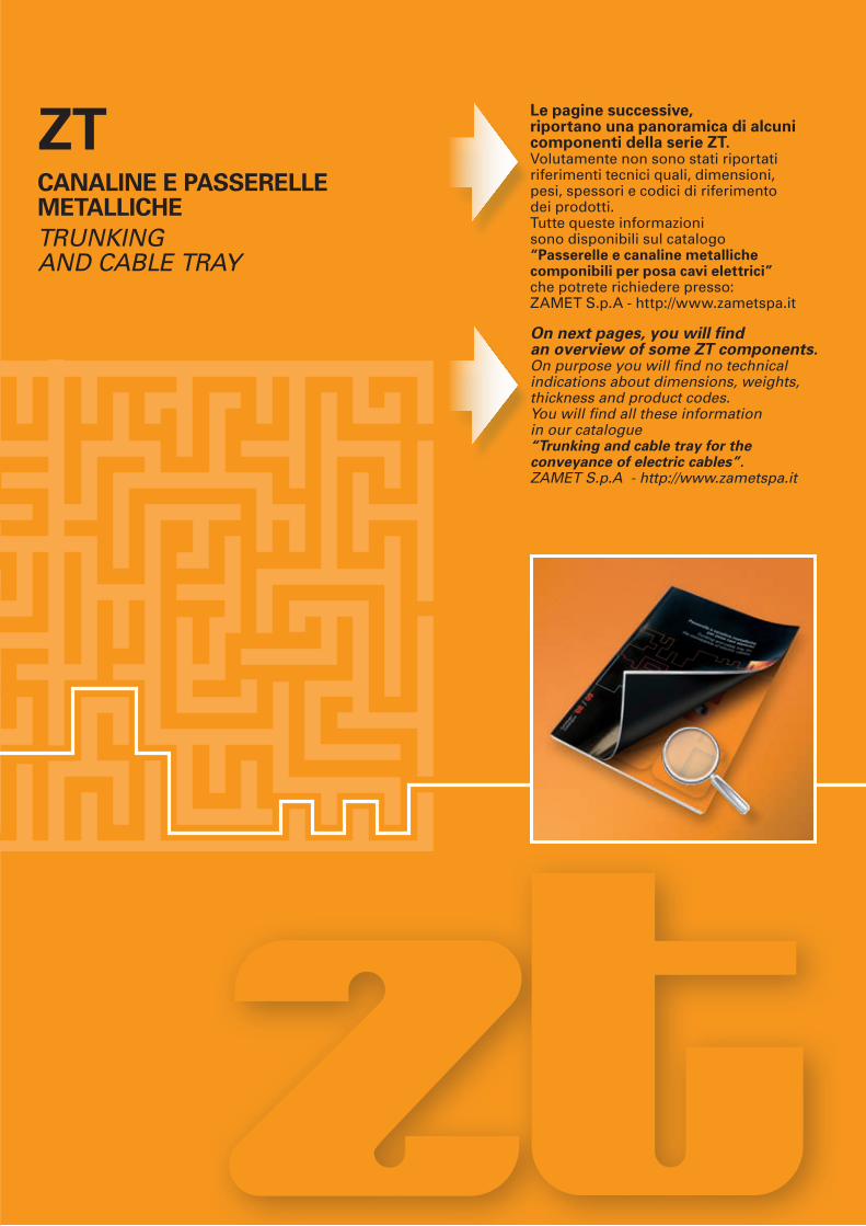
ZTCANALINE E PASSErELLE METALLIChETrunKIng AnD CAblE TrAy
Le pagine successive, riportano una panoramica di alcuni componenti della serie ZT. Volutamente non sono stati riportati riferimenti tecnici quali, dimensioni, pesi, spessori e codici di riferimento dei prodotti. Tutte queste informazioni sono disponibili sul catalogo “Passerelle e canaline metalliche componibili per posa cavi elettrici” che potrete richiedere presso:ZAMET S.p.A - http://www.zametspa.it
On next pages, you will find an overview of some ZT components. On purpose you will find no technical indications about dimensions, weights, thickness and product codes. you will find all these information in our catalogue “Trunking and cable tray for the conveyance of electric cables”.ZAMET S.p.A - http://www.zametspa.it
54
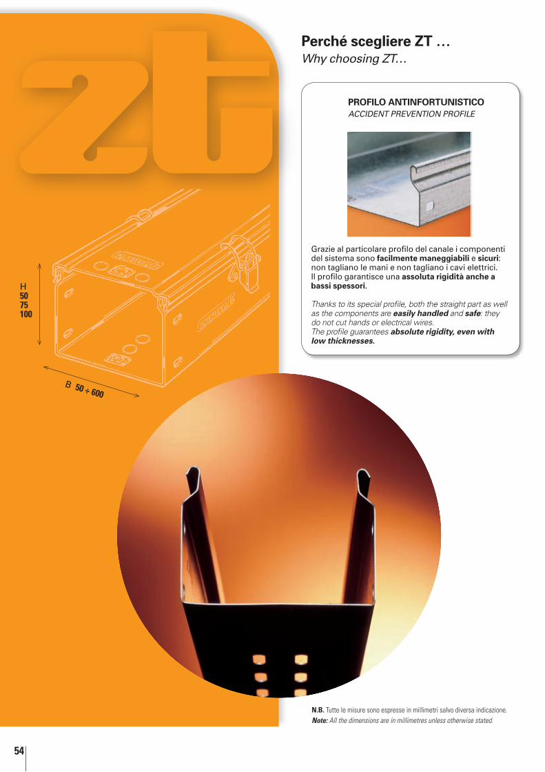
Perché scegliere ZT …Why choosing ZT…
Grazie al particolare profilo del canale i componenti del sistema sono facilmente maneggiabili e sicuri: non tagliano le mani e non tagliano i cavi elettrici.Il profilo garantisce una assoluta rigidità anche a bassi spessori.
Thanks to its special profile, both the straight part as well as the components are easily handled and safe: they do not cut hands or electrical wires.The profile guarantees absolute rigidity, even with low thicknesses.
PrOFILO ANTINFOrTUNISTICOACCIDEnT PrEVEnTIOn PrOFIlE
H 50 75 100
B 50 ÷ 600
N.B. Tutte le misure sono espresse in millimetri salvo diversa indicazione.Note: All the dimensions are in millimetres unless otherwise stated.
55
50H
75H
100H
3000
50 7
10
3000
10
757
3000
100
7
10
75
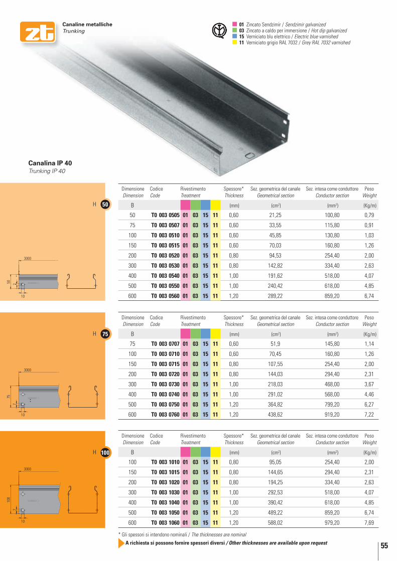
Dimensione Dimension
Codice Code
Rivestimento Treatment
Spessore* Thickness
Sez. geometrica del canale Geometrical section
Sez. intesa come conduttore Conductor section
Peso Weight
B (mm) (cm2) (mm2) (Kg/m)
50 T0 003 0505 01 03 15 11 0,60 21,25 100,80 0,79
75 T0 003 0507 01 03 15 11 0,60 33,55 115,80 0,91
100 T0 003 0510 01 03 15 11 0,60 45,85 130,80 1,03
150 T0 003 0515 01 03 15 11 0,60 70,03 160,80 1,26
200 T0 003 0520 01 03 15 11 0,80 94,53 254,40 2,00
300 T0 003 0530 01 03 15 11 0,80 142,82 334,40 2,63
400 T0 003 0540 01 03 15 11 1,00 191,62 518,00 4,07
500 T0 003 0550 01 03 15 11 1,00 240,42 618,00 4,85
600 T0 003 0560 01 03 15 11 1,20 289,22 859,20 6,74
Dimensione Dimension
Codice Code
Rivestimento Treatment
Spessore* Thickness
Sez. geometrica del canale Geometrical section
Sez. intesa come conduttore Conductor section
Peso Weight
B (mm) (cm2) (mm2) (Kg/m)
75 T0 003 0707 01 03 15 11 0,60 51,9 145,80 1,14
100 T0 003 0710 01 03 15 11 0,60 70,45 160,80 1,26
150 T0 003 0715 01 03 15 11 0,80 107,55 254,40 2,00
200 T0 003 0720 01 03 15 11 0,80 144,03 294,40 2,31
300 T0 003 0730 01 03 15 11 1,00 218,03 468,00 3,67
400 T0 003 0740 01 03 15 11 1,00 291,02 568,00 4,46
500 T0 003 0750 01 03 15 11 1,20 364,82 799,20 6,27
600 T0 003 0760 01 03 15 11 1,20 438,62 919,20 7,22
Dimensione Dimension
Codice Code
Rivestimento Treatment
Spessore* Thickness
Sez. geometrica del canale Geometrical section
Sez. intesa come conduttore Conductor section
Peso Weight
B (mm) (cm2) (mm2) (Kg/m)
100 T0 003 1010 01 03 15 11 0,80 95,05 254,40 2,00
150 T0 003 1015 01 03 15 11 0,80 144,65 294,40 2,31
200 T0 003 1020 01 03 15 11 0,80 194,25 334,40 2,63
300 T0 003 1030 01 03 15 11 1,00 292,53 518,00 4,07
400 T0 003 1040 01 03 15 11 1,00 390,42 618,00 4,85
500 T0 003 1050 01 03 15 11 1,20 489,22 859,20 6,74
600 T0 003 1060 01 03 15 11 1,20 588,02 979,20 7,69
Canaline metalliche Trunking
* Gli spessori si intendono nominali / The thicknesses are nominal
A richiesta si possono fornire spessori diversi / other thicknesses are available upon request
01 Zincato Sendzimir / Sendzimir galvanized 03 Zincato a caldo per immersione / Hot dip galvanized 15 Verniciato blu elettrico / Electric blue varnished 11 Verniciato grigio RAL 7032 / Grey RAL 7032 varnished
Canalina IP 40Trunking IP 40

56
50H
75H
100H
3000
50 7
10
3000
10
757
3000
100
7
10
Canaline metalliche Trunking
Passerella asolata IP 20Perforated cable tray IP 20
Dimensione Dimension
Codice Code
Rivestimento Treatment
Spessore* Thickness
Sez. geometrica del canale Geometrical section
Sez. intesa come conduttore Conductor section
Peso Weight
B (mm) (cm2) (mm2) (Kg/m)
50 T0 013 0505 01 03 15 11 0,60 21,25 100,80 0,78
75 T0 013 0507 01 03 15 11 0,60 33,55 115,80 0,88
100 T0 013 0510 01 03 15 11 0,60 45,85 130,80 0,99
150 T0 013 0515 01 03 15 11 0,60 70,03 160,80 1,20
200 T0 013 0520 01 03 15 11 0,80 94,53 254,40 1,85
300 T0 013 0530 01 03 15 11 0,80 142,82 334,40 2,39
400 T0 013 0540 01 03 15 11 1,00 191,62 518,00 3,67
500 T0 013 0550 01 03 15 11 1,00 240,42 618,00 4,35
600 T0 013 0560 01 03 15 11 1,20 289,22 859,20 6,04
Dimensione Dimension
Codice Code
Rivestimento Treatment
Spessore* Thickness
Sez. geometrica del canale Geometrical section
Sez. intesa come conduttore Conductor section
Peso Weight
B (mm) (cm2) (mm2) (Kg/m)
75 T0 013 0707 01 03 15 11 0,60 51,9 145,80 1,11
100 T0 013 0710 01 03 15 11 0,60 70,45 160,80 1,23
150 T0 013 0715 01 03 15 11 0,80 107,55 254,40 1,90
200 T0 013 0720 01 03 15 11 0,80 144,03 294,40 2,17
300 T0 013 0730 01 03 15 11 1,00 218,03 468,00 3,39
400 T0 013 0740 01 03 15 11 1,00 291,02 568,00 4,07
500 T0 013 0750 01 03 15 11 1,20 364,82 799,20 5,70
600 T0 013 0760 01 03 15 11 1,20 438,62 919,20 6,51
Dimensione Dimension
Codice Code
Rivestimento Treatment
Spessore* Thickness
Sez. geometrica del canale Geometrical section
Sez. intesa come conduttore Conductor section
Peso Weight
B (mm) (cm2) (mm2) (Kg/m)
100 T0 013 1010 01 03 15 11 0,80 95,05 254,40 1,95
150 T0 013 1015 01 03 15 11 0,80 144,65 294,40 2,22
200 T0 013 1020 01 03 15 11 0,80 194,25 334,40 2,48
300 T0 013 1030 01 03 15 11 1,00 292,53 518,00 3,79
400 T0 013 1040 01 03 15 11 1,00 390,42 618,00 4,46
500 T0 013 1050 01 03 15 11 1,20 489,22 859,20 6,17
600 T0 013 1060 01 03 15 11 1,20 588,02 979,20 6,98
01 Zincato Sendzimir / Sendzimir galvanized 03 Zincato a caldo per immersione / Hot dip galvanized 15 Verniciato blu elettrico / Electric blue varnished 11 Verniciato grigio RAL 7032 / Grey RAL 7032 varnished
* Gli spessori si intendono nominali / The thicknesses are nominal
A richiesta si possono fornire spessori diversi / other thicknesses are available upon request
Nervatura sul fondo: dalla misura 300 Rib at the bottom: by the measure 300
57
B
L
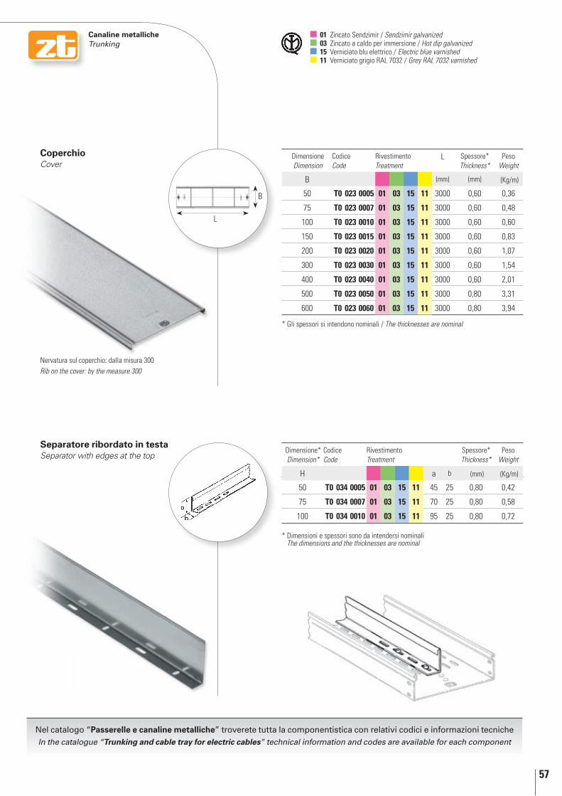
Canaline metalliche Trunking
Dimensione Dimension
Codice Code
Rivestimento Treatment
L Spessore* Thickness*
Peso Weight
B (mm) (mm) (Kg/m)
50 T0 023 0005 01 03 15 11 3000 0,60 0,36
75 T0 023 0007 01 03 15 11 3000 0,60 0,48
100 T0 023 0010 01 03 15 11 3000 0,60 0,60
150 T0 023 0015 01 03 15 11 3000 0,60 0,83
200 T0 023 0020 01 03 15 11 3000 0,60 1,07
300 T0 023 0030 01 03 15 11 3000 0,60 1,54
400 T0 023 0040 01 03 15 11 3000 0,60 2,01
500 T0 023 0050 01 03 15 11 3000 0,80 3,31
600 T0 023 0060 01 03 15 11 3000 0,80 3,94
Dimensione* Dimension*
Codice Code
Rivestimento Treatment
Spessore* Thickness*
Peso Weight
H a b (mm) (Kg/m)
50 T0 034 0005 01 03 15 11 45 25 0,80 0,42
75 T0 034 0007 01 03 15 11 70 25 0,80 0,58
100 T0 034 0010 01 03 15 11 95 25 0,80 0,72
Separatore ribordato in testaSeparator with edges at the top
CoperchioCover
01 Zincato Sendzimir / Sendzimir galvanized 03 Zincato a caldo per immersione / Hot dip galvanized 15 Verniciato blu elettrico / Electric blue varnished 11 Verniciato grigio RAL 7032 / Grey RAL 7032 varnished
* Dimensioni e spessori sono da intendersi nominali The dimensions and the thicknesses are nominal
* Gli spessori si intendono nominali / The thicknesses are nominal
Nervatura sul coperchio: dalla misura 300Rib on the cover: by the measure 300
Nel catalogo “Passerelle e canaline metalliche” troverete tutta la componentistica con relativi codici e informazioni tecnicheIn the catalogue “Trunking and cable tray for electric cables” technical information and codes are available for each component
58
L
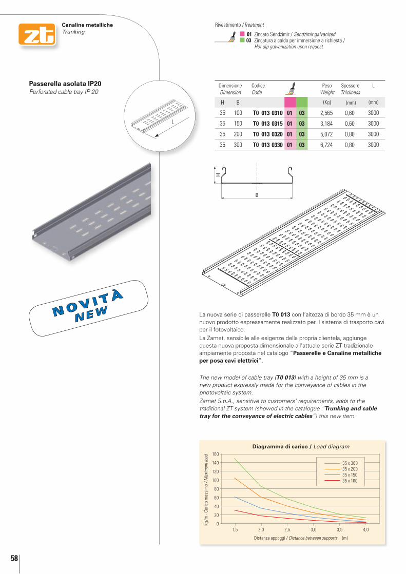
Canaline metalliche Trunking 01 Zincato Sendzimir / Sendzimir galvanized
03 Zincatura a caldo per immersione a richiesta / Hot dip galvanization upon request
Rivestimento /Treatment
Dimensione Dimension
Codice Code
Peso Weight
Spessore Thickness
L
H B (Kg) (mm) (mm)
35 100 T0 013 0310 01 03 2,565 0,60 3000
35 150 T0 013 0315 01 03 3,184 0,60 3000
35 200 T0 013 0320 01 03 5,072 0,80 3000
35 300 T0 013 0330 01 03 6,724 0,80 3000
Passerella asolata IP20Perforated cable tray IP 20
La nuova serie di passerelle T0 013 con l’altezza di bordo 35 mm è un nuovo prodotto espressamente realizzato per il sistema di trasporto cavi per il fotovoltaico.
La Zamet, sensibile alle esigenze della propria clientela, aggiunge questa nuova proposta dimensionale all’attuale serie ZT tradizionale ampiamente proposta nel catalogo “Passerelle e Canaline metalliche per posa cavi elettrici”.
The new model of cable tray (T0 013) with a height of 35 mm is a new product expressly made for the conveyance of cables in the photovoltaic system.
Zamet S.p.A., sensitive to customers’ requirements, adds to the traditional ZT system (showed in the catalogue “Trunking and cable tray for the conveyance of electric cables”) this new item.
Kg/m
- Ca
rico
mas
sim
o / M
axim
um lo
ad
Distanza appoggi / Distance between supports (m)
Diagramma di carico / load diagram160
140
120
100
80
60
40
20
01,5 2,0 2,5 3,53,0 4,0
35 x 30035 x 20035 x 15035 x 100
N o v i t à
n E w
59
Canaline metalliche Trunking
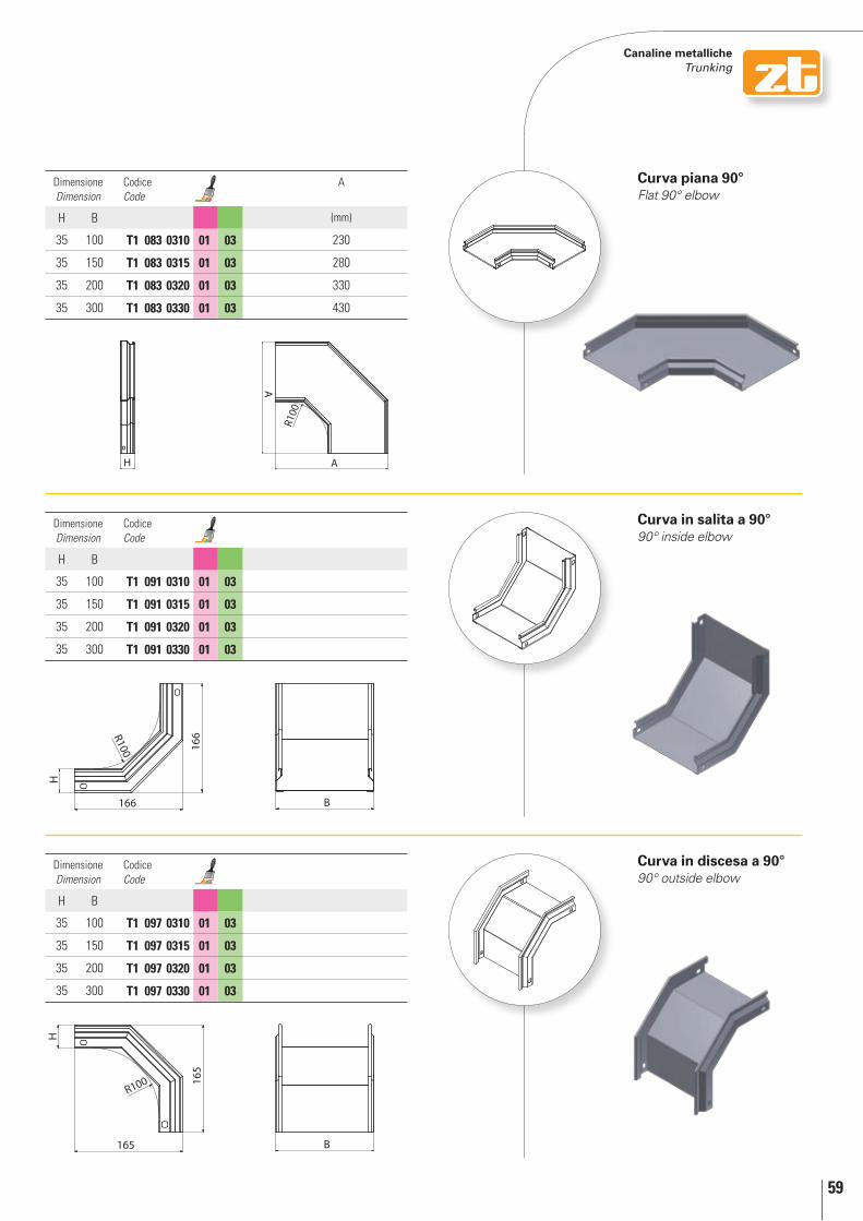
Curva piana 90°Flat 90° elbow
Dimensione Dimension
Codice Code
A
H B (mm)
35 100 T1 083 0310 01 03 230
35 150 T1 083 0315 01 03 280
35 200 T1 083 0320 01 03 330
35 300 T1 083 0330 01 03 430
Dimensione Dimension
Codice Code
H B
35 100 T1 091 0310 01 03
35 150 T1 091 0315 01 03
35 200 T1 091 0320 01 03
35 300 T1 091 0330 01 03
Dimensione Dimension
Codice Code
H B
35 100 T1 097 0310 01 03
35 150 T1 097 0315 01 03
35 200 T1 097 0320 01 03
35 300 T1 097 0330 01 03
Curva in salita a 90°90° inside elbow
Curva in discesa a 90°90° outside elbow
60
Canaline metalliche Trunking 01 Zincato Sendzimir / Sendzimir galvanized
03 Zincatura a caldo per immersione a richiesta / Hot dip galvanization upon request
Rivestimento /Treatment
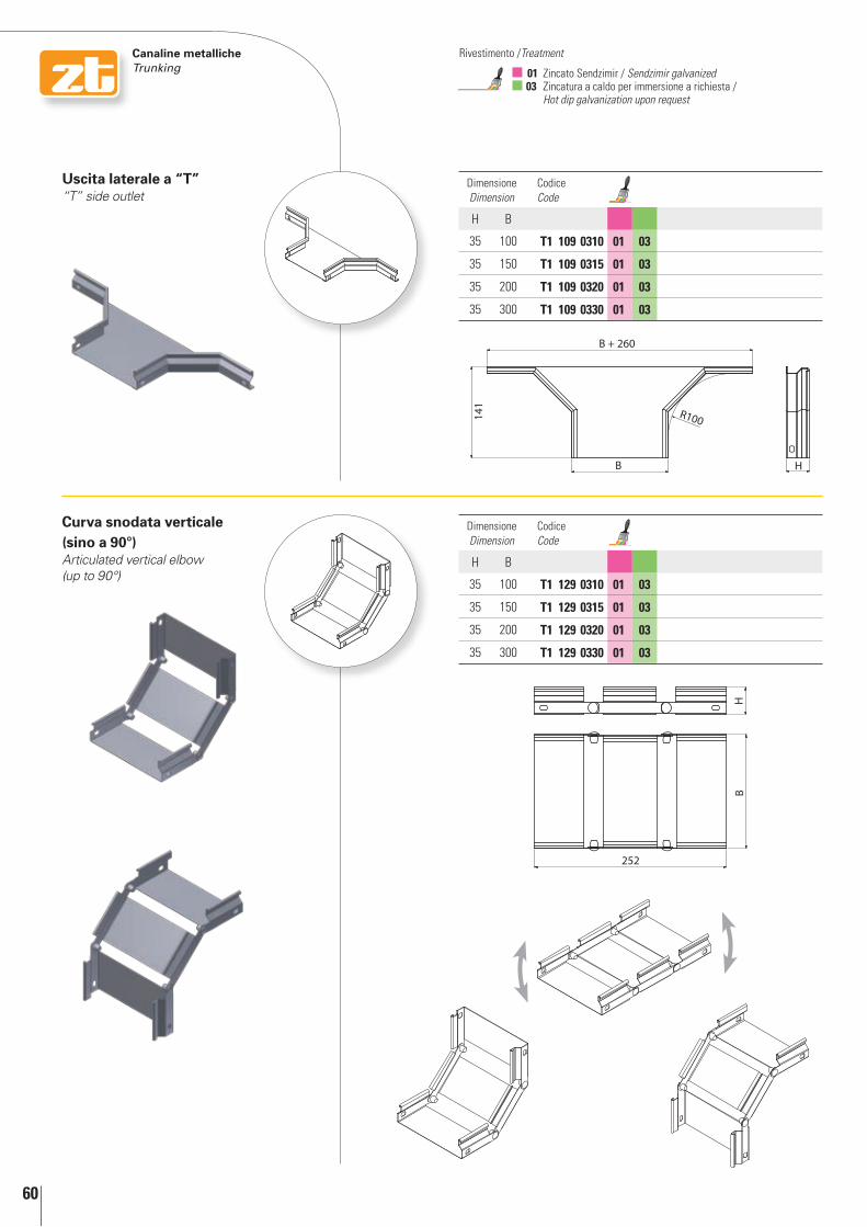
Curva snodata verticale (sino a 90°)Articulated vertical elbow (up to 90°)
Uscita laterale a “T”“T” side outlet
Dimensione Dimension
Codice Code
H B
35 100 T1 109 0310 01 03
35 150 T1 109 0315 01 03
35 200 T1 109 0320 01 03
35 300 T1 109 0330 01 03
Dimensione Dimension
Codice Code
H B
35 100 T1 129 0310 01 03
35 150 T1 129 0315 01 03
35 200 T1 129 0320 01 03
35 300 T1 129 0330 01 03
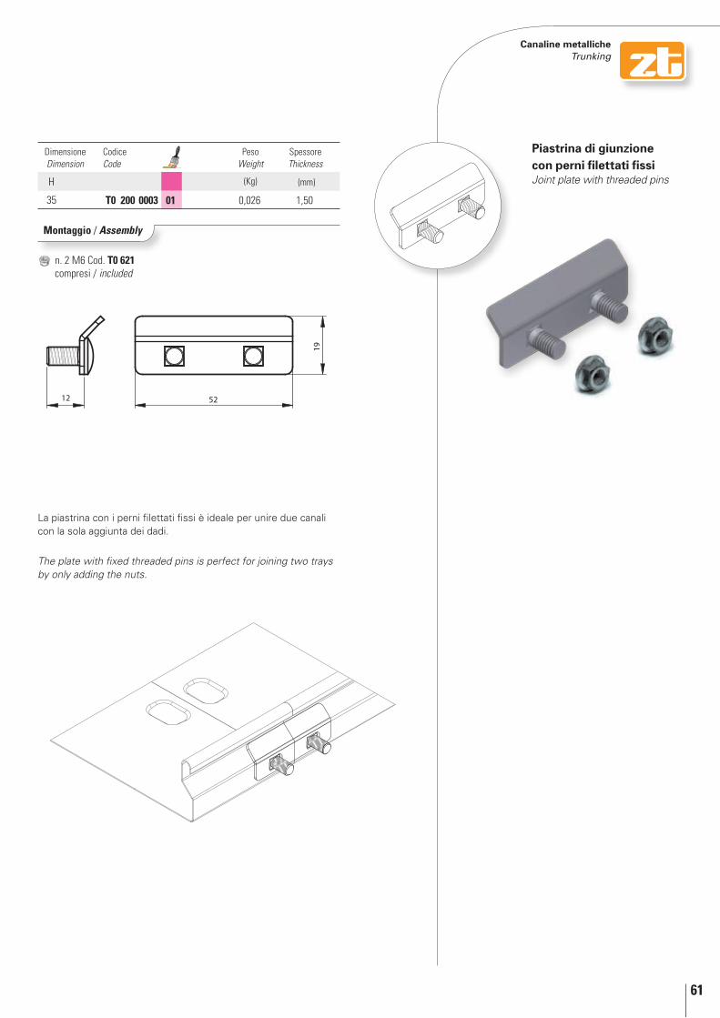
61
12 52
19
Canaline metalliche Trunking
Piastrina di giunzione con perni filettati fissiJoint plate with threaded pins
Dimensione Dimension
Codice Code
Peso Weight
Spessore Thickness
H (Kg) (mm)
35 T0 200 0003 01 0,026 1,50
Montaggio / Assembly
n. 2 M6 Cod. T0 621 compresi / included
La piastrina con i perni filettati fissi è ideale per unire due canali con la sola aggiunta dei dadi.
The plate with fixed threaded pins is perfect for joining two trays by only adding the nuts.
Le pagine successive, riportano una panoramica di alcuni componenti della serie Zr. Volutamente non sono stati riportati riferimenti tecnici quali, dimensioni, pesi, spessori e codici di riferimento dei prodotti. Tutte queste informazioni sono disponibili sul catalogo “Passerelle e canaline metalliche componibili per posa cavi elettrici” che potrete richiedere presso:ZAMET S.p.A - http://www.zametspa.it
On next pages, you will find an overview of some ZR components. On purpose you will find no technical indications about dimensions, weights, thickness and product codes. you will find all these information in our catalogue “Trunking and cable tray for the conveyance of electric cables”.ZAMET S.p.A - http://www.zametspa.it
Zr PASSErELLE METALLIChE A FILObASKET TrAy
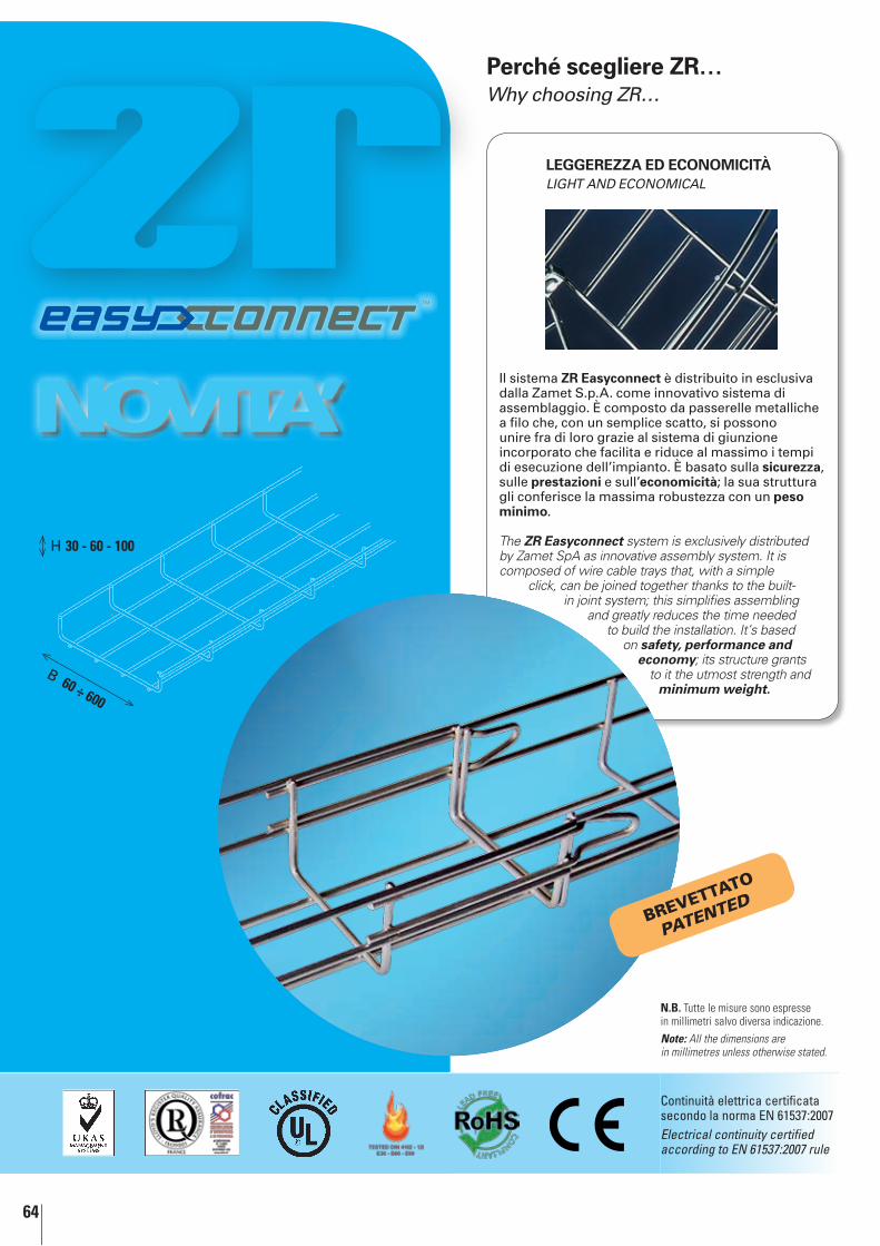
64
H 30 - 60 - 100
B 60 ÷ 600
Novita’Il sistema Zr Easyconnect è distribuito in esclusiva dalla Zamet S.p.A. come innovativo sistema di assemblaggio. È composto da passerelle metalliche a filo che, con un semplice scatto, si possono unire fra di loro grazie al sistema di giunzione incorporato che facilita e riduce al massimo i tempi di esecuzione dell’impianto. È basato sulla sicurezza, sulle prestazioni e sull’economicità; la sua struttura gli conferisce la massima robustezza con un peso minimo.
The ZR Easyconnect system is exclusively distributed by Zamet SpA as innovative assembly system. It is composed of wire cable trays that, with a simple
click, can be joined together thanks to the built-in joint system; this simplifies assembling
and greatly reduces the time needed to build the installation. It’s based
on safety, performance and economy; its structure grants
to it the utmost strength and minimum weight.
LEGGErEZZA ED ECONOMICITÀlIgHT AnD ECOnOMICAl
Perché scegliere Zr…Why choosing Zr…
N.B. Tutte le misure sono espresse in millimetri salvo diversa indicazione.Note: All the dimensions are in millimetres unless otherwise stated.
Brevettato
PATENTED
Continuità elettrica certificata secondo la norma EN 61537:2007Electrical continuity certified according to EN 61537:2007 rule
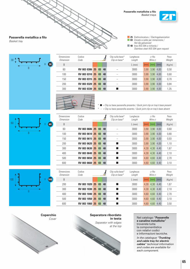
65
60H
100H
30H30
B
60
B
100
B
Dimensione Dimension
Codice Code
Clip sulla base* Clip on base*
Lunghezza Length
filo Wire
Peso Weight
B L (mm) [mm] [mm] [mm] (Kg/m)
60 RV 003 0306 25 03 40 – 3000 3,90 3,90 4,00 0,50
100 RV 003 0310 25 03 40 – 3000 3,90 3,90 4,00 0,60
150 RV 003 0315 25 03 40 – 3000 3,90 3,90 4,00 0,70
200 RV 003 0320 25 03 40 – 3000 3,90 3,90 4,00 0,84
300 RV 003 0330 25 03 40 n 3000 3,90 3,90 4,00 1,35
Dimensione Dimension
Codice Code
Clip sulla base* Clip on base*
Lunghezza Length
filo Wire
Peso Weight
B L (mm) [mm] [mm] [mm] (Kg/m)
200 RV 003 1020 25 03 40 n 3000 4,30 4,30 4,40 1,67
300 RV 003 1030 25 03 40 n 3000 4,30 4,30 4,40 2,10
400 RV 003 1040 25 03 40 n 3000 4,60 4,60 4,40 2,70
500 RV 003 1050 25 03 40 n 3000 4,60 4,60 4,40 3,10
600 RV 003 1060 25 03 40 n 3000 4,60 4,60 4,40 3,50
Dimensione Dimension
Codice Code
Clip sulla base* Clip on base*
Lunghezza Length
filo Wire
Peso Weight
B L (mm) [mm] [mm] [mm] (Kg/m)
60 RV 003 0606 25 03 40 – 3000 3,90 3,90 4,00 0,60
100 RV 003 0610 25 03 40 – 3000 3,90 3,90 4,00 0,80
150 RV 003 0615 25 03 40 – 3000 3,90 3,90 4,00 0,93
200 RV 003 0620 25 03 40 n 3000 3,90 3,90 4,00 1,10
300 RV 003 0630 25 03 40 n 3000 4,30 4,30 4,40 1,67
400 RV 003 0640 25 03 40 n 3000 4,30 4,30 4,40 2,10
500 RV 003 0650 25 03 40 n 3000 4,60 4,60 4,40 2,70
600 RV 003 0660 25 03 40 n 3000 4,60 4,60 4,40 3,10
Passerelle metalliche a filo Basket trays
25 Elettrozincatura / Electrogalvanization 03 Zincato a caldo per immersione /
Hot dip galvanized 40 Inox AISI 304 a richiesta /
Stainless steel AISI 304 upon request
CoperchioCover
Separatore ribordato in testa
Separator with edges at the top
Passerella metallica a filoBasket tray
* n = Clip su base passerella presente / Quick joint clip on tray’s base present* – = Clip su base passerella assente / Quick joint clip on tray’s base absent
Nel catalogo “Passerelle e canaline metalliche” troverete tutta la componentistica con relativi codici e informazioni tecniche.In the catalogue “Trunking and cable tray for electric cables” technical information and codes are available for each component.
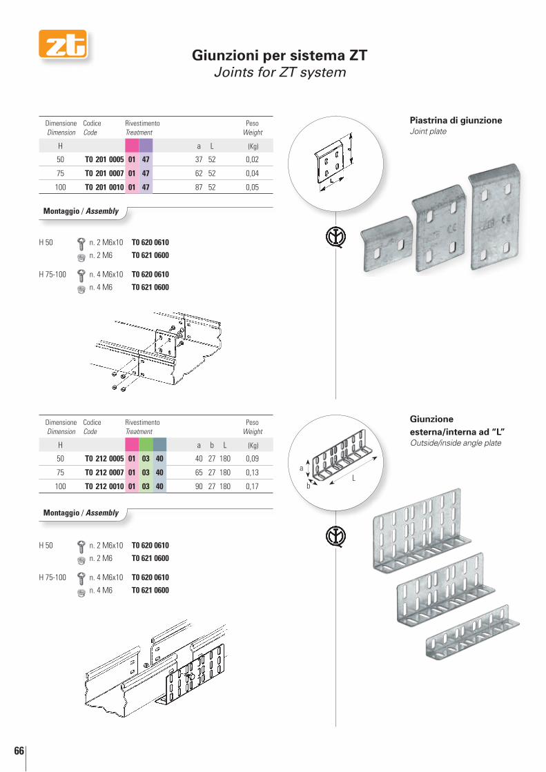
66
H 50 n. 2 M6x10 T0 620 0610
n. 2 M6 T0 621 0600
H 50 n. 2 M6x10 T0 620 0610
n. 2 M6 T0 621 0600
H 75-100 n. 4 M6x10 T0 620 0610
n. 4 M6 T0 621 0600
H 75-100 n. 4 M6x10 T0 620 0610
n. 4 M6 T0 621 0600
La
b
Montaggio / Assembly
Montaggio / Assembly
Dimensione Dimension
Codice Code
Rivestimento Treatment
Peso Weight
H a L (Kg)
50 T0 201 0005 01 47 37 52 0,02
75 T0 201 0007 01 47 62 52 0,04
100 T0 201 0010 01 47 87 52 0,05
Dimensione Dimension
Codice Code
Rivestimento Treatment
Peso Weight
H a b L (Kg)
50 T0 212 0005 01 03 40 40 27 180 0,09
75 T0 212 0007 01 03 40 65 27 180 0,13
100 T0 212 0010 01 03 40 90 27 180 0,17
Piastrina di giunzioneJoint plate
Giunzione esterna/interna ad “L”Outside/inside angle plate
Giunzioni per sistema ZTJoints for ZT system
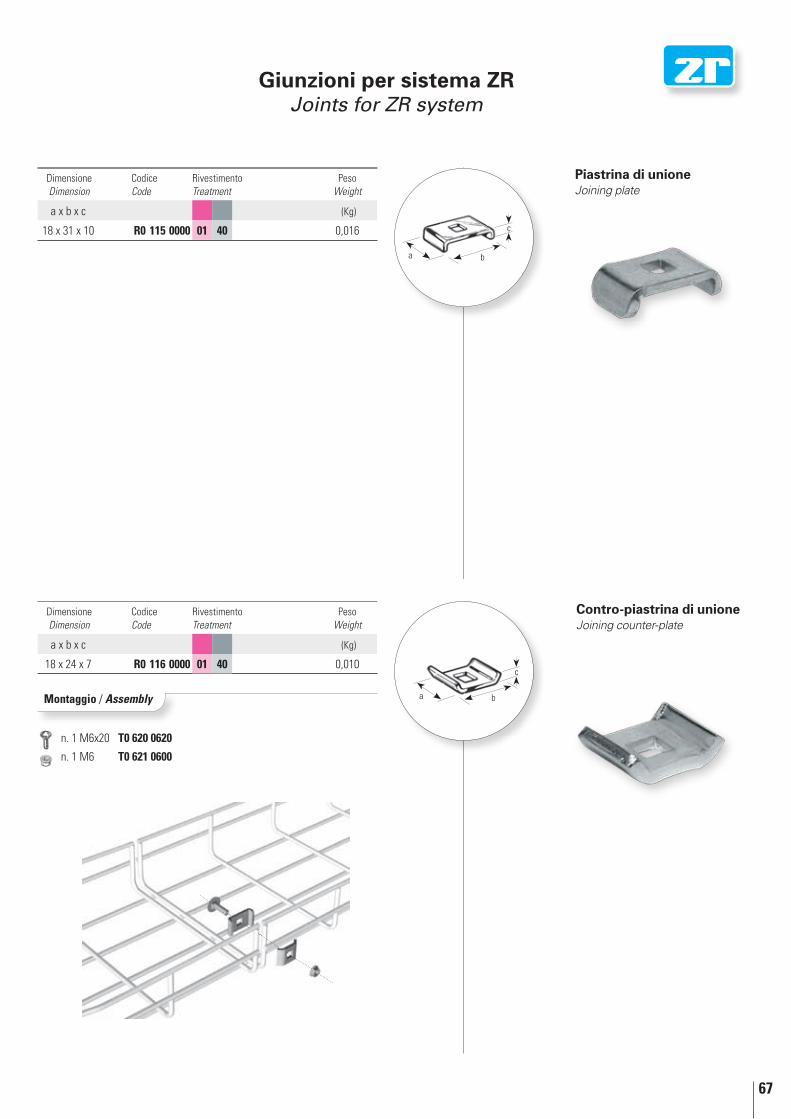
67
n. 1 M6x20 T0 620 0620
n. 1 M6 T0 621 0600
b
c
a
b
c
a
Piastrina di unioneJoining plate
Dimensione Dimension
Codice Code
Rivestimento Treatment
Peso Weight
a x b x c (Kg)
18 x 31 x 10 R0 115 0000 01 40 0,016
Contro-piastrina di unioneJoining counter-plate
Dimensione Dimension
Codice Code
Rivestimento Treatment
Peso Weight
a x b x c (Kg)
18 x 24 x 7 R0 116 0000 01 40 0,010
Montaggio / Assembly
Giunzioni per sistema ZrJoints for Zr system
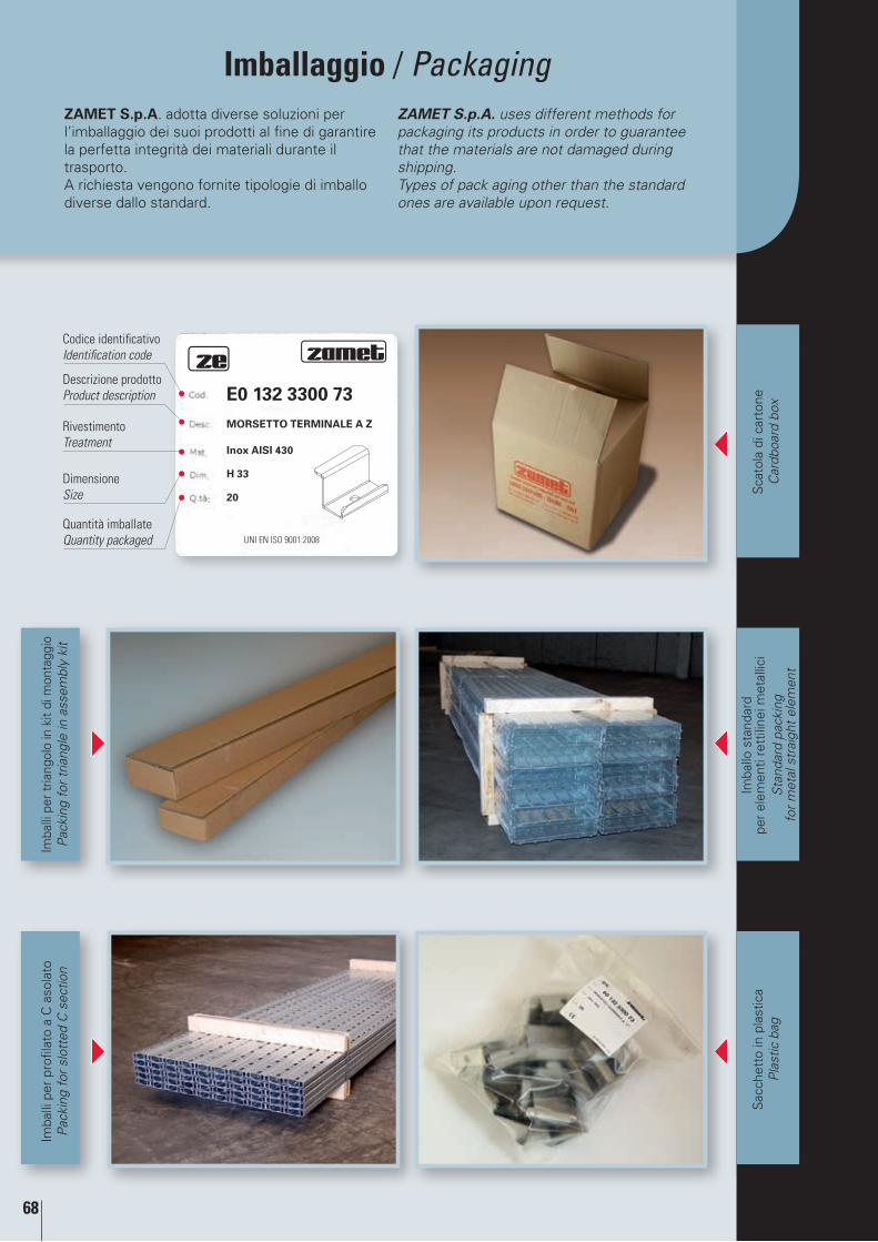
68
Imballaggio / Packaging
Imba
llo s
tand
ard
pe
r el
emen
ti re
ttili
nei m
etal
lici
Sta
ndar
d pa
ckin
g
for
met
al s
trai
ght
elem
ent
Sca
tola
di c
arto
ne
Car
dboa
rd b
ox
Imba
lli p
er t
riang
olo
in k
it di
mon
tagg
ioP
acki
ng f
or t
riang
le in
ass
embl
y ki
t
Sac
chet
to in
pla
stic
a P
last
ic b
ag
Imba
lli p
er p
rofil
ato
a C
aso
lato
Pac
king
for
slo
tted
C s
ectio
n
UNI EN ISO 9001:2008
E0 132 3300 73MOrSETTO TErMINALE A Z
Inox AISI 430
h 33
20
Rivestimento Treatment
Codice identificativoIdentification code
Dimensione Size
Quantità imballate Quantity packaged
Descrizione prodotto Product description
ZAMET S.p.A. adotta diverse soluzioni per l’imballaggio dei suoi prodotti al fine di garantire la perfetta integrità dei materiali durante il trasporto.A richiesta vengono fornite tipologie di imballo diverse dallo standard.
ZAMET S.p.A. uses different methods for packaging its products in order to guarantee that the materials are not damaged during shipping.Types of pack aging other than the standard ones are available upon request.
Indice completoTable of contents

70
Ind
ice
com
ple
to
Tab
le o
f co
nte
nts Zamet . . . . . . . . . . . . . . . . . . . . . . . . . . . . . . . . . . . . . . . . . . . . . . . . . . . . . . . . . . . . . . . . . . . . 2
L’AZIENdA . . . . . . . . . . . . . . . . . . . . . . . . . . . . . . . . . . . . . . . . . . . . . . . . . . . . . . . . . . . . . . . . . . . . 4
CERTIFICAZIONE dI SISTEMA ISO 9001:2008 . . . . . . . . . . . . . . . 6
CHE COSA SONO GLI ACCIAI INOSSIdABILI . . . . . . . . . . . . . . . . 7
CARATTERISTICHE MECCANICHE Ed IMPIEGHI . . . . . . . . . . 8
MATERIALI E RIvESTIMENTI PROTETTIvI . . . . . . . . . . . . . . . . . . . 9
Zincatura a caldo processo Sendzimir . . . . . . . . . . . . . . . . . . . . . . . . . . . . . . . . . . 9
Zincatura a caldo per immersione . . . . . . . . . . . . . . . . . . . . . . . . . . . . . . . . . . . . . . . 9
Acciaio INOX . . . . . . . . . . . . . . . . . . . . . . . . . . . . . . . . . . . . . . . . . . . . . . . . . . . . . . . . . . . . . . . . . 10
Geomet® 321 . . . . . . . . . . . . . . . . . . . . . . . . . . . . . . . . . . . . . . . . . . . . . . . . . . . . . . . . . . . . . . . . . 10
Materiali e rivestimenti protettivi: campi di applicazione . . . . . 11
Sistema ZE
ZAMET PRESENTA LA SERIE ZE . . . . . . . . . . . . . . . . . . . . . . . . . . . . . . . . . . 14
Profilato a “C” asolato . . . . . . . . . . . . . . . . . . . . . . . . . . . . . . . . . . . . . . . . . . . . . . . . . . . . . 16
Elemento di regolazione . . . . . . . . . . . . . . . . . . . . . . . . . . . . . . . . . . . . . . . . . . . . . . . . . . . 18
Elemento per fissaggio sistema ZT/ZE . . . . . . . . . . . . . . . . . . . . . . . . . . . . . . . 18
Giunto tra profilato a “C” a fissaggio interno . . . . . . . . . . . . . . . . . . . . . . . 20
Giunto tra profilato a “C” a fissaggio con bulloni . . . . . . . . . . . . . . . . . . 20
Elemento di sostegno . . . . . . . . . . . . . . . . . . . . . . . . . . . . . . . . . . . . . . . . . . . . . . . . . . . . . . 22
Giunto per triangoli ad inclinazione variabile . . . . . . . . . . . . . . . . . . . . . . . 22
Giunto per triangolia montaggio rapido . . . . . . . . . . . . . . . . . . . . . . . . . . . . . . 24
Giunto per triangoli a 30° a fissaggio interno . . . . . . . . . . . . . . . . . . . . . . 26
Giunto per triangoli a 60° . . . . . . . . . . . . . . . . . . . . . . . . . . . . . . . . . . . . . . . . . . . . . . . . . 26
Giunto per triangoli a 90° . . . . . . . . . . . . . . . . . . . . . . . . . . . . . . . . . . . . . . . . . . . . . . . . . 26
Giunto per triangoli a 30° a fissaggio con bulloni . . . . . . . . . . . . . . . . . 28
Giunto per triangoli a 60° a fissaggio con bulloni . . . . . . . . . . . . . . . . . 28
Giunto per triangoli a 90° a fissaggio con bulloni . . . . . . . . . . . . . . . . . 28
Morsetto terminale a “Z” . . . . . . . . . . . . . . . . . . . . . . . . . . . . . . . . . . . . . . . . . . . . . . . . . 30
Morsetto intermedio ad “Ω” . . . . . . . . . . . . . . . . . . . . . . . . . . . . . . . . . . . . . . . . . . . 30
Morsetto terminale a “Z” regolabile . . . . . . . . . . . . . . . . . . . . . . . . . . . . . . . . . . 32
Morsetto intermedio ad "Ω“ rinforzato . . . . . . . . . . . . . . . . . . . . . . . . . . . . . 32
Piastrina con perno M8x50 . . . . . . . . . . . . . . . . . . . . . . . . . . . . . . . . . . . . . . . . . . . . . . 34
Giunto per profilato a “C” . . . . . . . . . . . . . . . . . . . . . . . . . . . . . . . . . . . . . . . . . . . . . . . . . 34
Piastrina filettata M8 . . . . . . . . . . . . . . . . . . . . . . . . . . . . . . . . . . . . . . . . . . . . . . . . . . . . . . 36
Piastrina filettata M8 con molla . . . . . . . . . . . . . . . . . . . . . . . . . . . . . . . . . . . . . . . . 36
Supporto di fissaggio regolabile . . . . . . . . . . . . . . . . . . . . . . . . . . . . . . . . . . . . . . . . 38
Supporto di fissaggio a piastra regolabile . . . . . . . . . . . . . . . . . . . . . . . . . . . 38
Prolunga per supporto di fissaggio regolabile . . . . . . . . . . . . . . . . . . . . . . 40
Attacco a greca regolabile . . . . . . . . . . . . . . . . . . . . . . . . . . . . . . . . . . . . . . . . . . . . . . . 40
Zamet . . . . . . . . . . . . . . . . . . . . . . . . . . . . . . . . . . . . . . . . . . . . . . . . . . . . . . . . . . . . . . . . . . . . 2
THE CoMpANy . . . . . . . . . . . . . . . . . . . . . . . . . . . . . . . . . . . . . . . . . . . . . . . . . . . . . . . . . . . . . . 4
iso 9001:2008 sysTEM CERTifiCATioN . . . . . . . . . . . . . . . . . . . . . . . . . 6
WHAT ARE sTAiNLEss sTEELs . . . . . . . . . . . . . . . . . . . . . . . . . . . . . . . . . . . . . . 7
MECHANiCAL CHARACTERisTiCs ANd UsEs . . . . . . . . . . . . . . . 8
pRoTECTivE MATERiALs ANd CoATiNGs . . . . . . . . . . . . . . . . . . . . . 9
Galvanization (Sendzimir method) . . . . . . . . . . . . . . . . . . . . . . . . . . . . . . . . . . . . . . . . 9
Hot dip galvanizing . . . . . . . . . . . . . . . . . . . . . . . . . . . . . . . . . . . . . . . . . . . . . . . . . . . . . . . . . . . . 9
Stainless steel . . . . . . . . . . . . . . . . . . . . . . . . . . . . . . . . . . . . . . . . . . . . . . . . . . . . . . . . . . . . . . . . 10
Geomet® 321 . . . . . . . . . . . . . . . . . . . . . . . . . . . . . . . . . . . . . . . . . . . . . . . . . . . . . . . . . . . . . . . . . . 10
Protective materials and coatings: scope . . . . . . . . . . . . . . . . . . . . . . . . . . . . . 11
The ZE system
ZAMET pREsENTs ZE sERiEs . . . . . . . . . . . . . . . . . . . . . . . . . . . . . . . . . . . . . . 14
Slotted “C” section . . . . . . . . . . . . . . . . . . . . . . . . . . . . . . . . . . . . . . . . . . . . . . . . . . . . . . . . . 16
Adjustment element . . . . . . . . . . . . . . . . . . . . . . . . . . . . . . . . . . . . . . . . . . . . . . . . . . . . . . . . 18
Element for fixing ZT/ZE system . . . . . . . . . . . . . . . . . . . . . . . . . . . . . . . . . . . . . . . . . 18
Joint between “C” sections and internal fixing . . . . . . . . . . . . . . . . . . . . 20
Joint between “C” sections, bolt fixing . . . . . . . . . . . . . . . . . . . . . . . . . . . . . . . 20
Support element . . . . . . . . . . . . . . . . . . . . . . . . . . . . . . . . . . . . . . . . . . . . . . . . . . . . . . . . . . . . . 22
Joint for triangles with variable angle . . . . . . . . . . . . . . . . . . . . . . . . . . . . . . . . 22
Joint for triangles, rapid assembly . . . . . . . . . . . . . . . . . . . . . . . . . . . . . . . . . . . . . 24
Joint for 30° triangles (internal fixing) . . . . . . . . . . . . . . . . . . . . . . . . . . . . . . . . 26
Joint for 60° triangles . . . . . . . . . . . . . . . . . . . . . . . . . . . . . . . . . . . . . . . . . . . . . . . . . . . . . . 26
Joint for 90° triangles . . . . . . . . . . . . . . . . . . . . . . . . . . . . . . . . . . . . . . . . . . . . . . . . . . . . . . 26
Joint for 30° triangles (bolt fixing) . . . . . . . . . . . . . . . . . . . . . . . . . . . . . . . . . . . . . . 28
Joint for 60° triangles (bolt fixing) . . . . . . . . . . . . . . . . . . . . . . . . . . . . . . . . . . . . . . 28
Joint for 90° triangles (bolt fixing) . . . . . . . . . . . . . . . . . . . . . . . . . . . . . . . . . . . . . . 28
“Z” terminal clamp . . . . . . . . . . . . . . . . . . . . . . . . . . . . . . . . . . . . . . . . . . . . . . . . . . . . . . . . . . 30
“Ω“ intermediate clamp . . . . . . . . . . . . . . . . . . . . . . . . . . . . . . . . . . . . . . . . . . . . . . . . . . 30
Adjustable “Z” terminal clamp . . . . . . . . . . . . . . . . . . . . . . . . . . . . . . . . . . . . . . . . . . 32
Reinforced "Ω“ intermediate clamp . . . . . . . . . . . . . . . . . . . . . . . . . . . . . . . . . . 32
Plate with M8x50 pin . . . . . . . . . . . . . . . . . . . . . . . . . . . . . . . . . . . . . . . . . . . . . . . . . . . . . . . 34
Joint for “C” section . . . . . . . . . . . . . . . . . . . . . . . . . . . . . . . . . . . . . . . . . . . . . . . . . . . . . . . . 34
Threaded M8 plate . . . . . . . . . . . . . . . . . . . . . . . . . . . . . . . . . . . . . . . . . . . . . . . . . . . . . . . . . . 36
Threaded M8 plate with spring . . . . . . . . . . . . . . . . . . . . . . . . . . . . . . . . . . . . . . . . . 36
Adjustable support fixing . . . . . . . . . . . . . . . . . . . . . . . . . . . . . . . . . . . . . . . . . . . . . . . . . . 38
Support fixing with adjustable plate . . . . . . . . . . . . . . . . . . . . . . . . . . . . . . . . . . . 38
Adjustable extension for fixing support . . . . . . . . . . . . . . . . . . . . . . . . . . . . . . . 40
Adjustable fretted joint . . . . . . . . . . . . . . . . . . . . . . . . . . . . . . . . . . . . . . . . . . . . . . . . . . . . 40
71
Ind
ice
com
ple
to
Tab
le o
f co
nte
ntsTriangle in assembly kit . . . . . . . . . . . . . . . . . . . . . . . . . . . . . . . . . . . . . . . . . . . . . . . . . . . . 42
Triangle in assembly kit . . . . . . . . . . . . . . . . . . . . . . . . . . . . . . . . . . . . . . . . . . . . . . . . . . . . 44
Upright for high load . . . . . . . . . . . . . . . . . . . . . . . . . . . . . . . . . . . . . . . . . . . . . . . . . . . . . . . 46
Joint for high load triangles . . . . . . . . . . . . . . . . . . . . . . . . . . . . . . . . . . . . . . . . . . . . . . 46
Universal support bracket . . . . . . . . . . . . . . . . . . . . . . . . . . . . . . . . . . . . . . . . . . . . . . . . . 48
Pipe collar . . . . . . . . . . . . . . . . . . . . . . . . . . . . . . . . . . . . . . . . . . . . . . . . . . . . . . . . . . . . . . . . . . . . . . 48
Quick clamp bracket for collar . . . . . . . . . . . . . . . . . . . . . . . . . . . . . . . . . . . . . . . . . . . 48
End slotted “C” section closure . . . . . . . . . . . . . . . . . . . . . . . . . . . . . . . . . . . . . . . . . 50
Adjustment tool . . . . . . . . . . . . . . . . . . . . . . . . . . . . . . . . . . . . . . . . . . . . . . . . . . . . . . . . . . . . . . 50
Profile cutter . . . . . . . . . . . . . . . . . . . . . . . . . . . . . . . . . . . . . . . . . . . . . . . . . . . . . . . . . . . . . . . . . . . 50
Overview ZT system
Trunking IP 40 . . . . . . . . . . . . . . . . . . . . . . . . . . . . . . . . . . . . . . . . . . . . . . . . . . . . . . . . . . . . . . . . . 55
Perforated cable tray IP 20 . . . . . . . . . . . . . . . . . . . . . . . . . . . . . . . . . . . . . . . . . . . . . . . . 56
Cover . . . . . . . . . . . . . . . . . . . . . . . . . . . . . . . . . . . . . . . . . . . . . . . . . . . . . . . . . . . . . . . . . . . . . . . . . . . . 57
Separator with edges at the top . . . . . . . . . . . . . . . . . . . . . . . . . . . . . . . . . . . . . . . . 57
Perforated cable tray IP 20 . . . . . . . . . . . . . . . . . . . . . . . . . . . . . . . . . . . . . . . . . . . . . . . . 58
Flat 90° elbow . . . . . . . . . . . . . . . . . . . . . . . . . . . . . . . . . . . . . . . . . . . . . . . . . . . . . . . . . . . . . . . . 59
90° inside elbow . . . . . . . . . . . . . . . . . . . . . . . . . . . . . . . . . . . . . . . . . . . . . . . . . . . . . . . . . . . . 59
90° outside elbow . . . . . . . . . . . . . . . . . . . . . . . . . . . . . . . . . . . . . . . . . . . . . . . . . . . . . . . . . . . 59
“T” side outlet . . . . . . . . . . . . . . . . . . . . . . . . . . . . . . . . . . . . . . . . . . . . . . . . . . . . . . . . . . . . . . . . 60
Articulated vertical elbow (up to 90°) . . . . . . . . . . . . . . . . . . . . . . . . . . . . . . . . . 60
Joint plate with threaded pins . . . . . . . . . . . . . . . . . . . . . . . . . . . . . . . . . . . . . . . . . . . 61
Joint plate . . . . . . . . . . . . . . . . . . . . . . . . . . . . . . . . . . . . . . . . . . . . . . . . . . . . . . . . . . . . . . . . . . . . . 66
Outside/inside angle plate . . . . . . . . . . . . . . . . . . . . . . . . . . . . . . . . . . . . . . . . . . . . . . . . 66
Overview ZR system
Basket tray . . . . . . . . . . . . . . . . . . . . . . . . . . . . . . . . . . . . . . . . . . . . . . . . . . . . . . . . . . . . . . . . . . . . . 65
Cover . . . . . . . . . . . . . . . . . . . . . . . . . . . . . . . . . . . . . . . . . . . . . . . . . . . . . . . . . . . . . . . . . . . . . . . . . . . . 65
Separator with edges at the top . . . . . . . . . . . . . . . . . . . . . . . . . . . . . . . . . . . . . . . . 65
Joining plate . . . . . . . . . . . . . . . . . . . . . . . . . . . . . . . . . . . . . . . . . . . . . . . . . . . . . . . . . . . . . . . . . . 67
Joining counter-plate . . . . . . . . . . . . . . . . . . . . . . . . . . . . . . . . . . . . . . . . . . . . . . . . . . . . . . . 67
Packaging . . . . . . . . . . . . . . . . . . . . . . . . . . . . . . . . . . . . . . . . . . . . . . . . . . . . . . . . . . . . . . . . 68
Triangolo in kit di montaggio . . . . . . . . . . . . . . . . . . . . . . . . . . . . . . . . . . . . . . . . . . . . . 42
Triangolo in kit di montaggio . . . . . . . . . . . . . . . . . . . . . . . . . . . . . . . . . . . . . . . . . . . . . 44
Montante per alte portate . . . . . . . . . . . . . . . . . . . . . . . . . . . . . . . . . . . . . . . . . . . . . . . 46
Giunto per triangoli alte portate . . . . . . . . . . . . . . . . . . . . . . . . . . . . . . . . . . . . . . . . 46
Staffa di supporto universale . . . . . . . . . . . . . . . . . . . . . . . . . . . . . . . . . . . . . . . . . . . 48
Collare serratubo . . . . . . . . . . . . . . . . . . . . . . . . . . . . . . . . . . . . . . . . . . . . . . . . . . . . . . . . . . . . 48
Staffa ad aggancio rapido per collare . . . . . . . . . . . . . . . . . . . . . . . . . . . . . . . . 48
Chiusura di testata per profilato a “C” . . . . . . . . . . . . . . . . . . . . . . . . . . . . . . . 50
Attrezzo di regolazione . . . . . . . . . . . . . . . . . . . . . . . . . . . . . . . . . . . . . . . . . . . . . . . . . . . . 50
Taglia profili . . . . . . . . . . . . . . . . . . . . . . . . . . . . . . . . . . . . . . . . . . . . . . . . . . . . . . . . . . . . . . . . . . . 50
Panoramica sistema ZT
Canalina IP 40 . . . . . . . . . . . . . . . . . . . . . . . . . . . . . . . . . . . . . . . . . . . . . . . . . . . . . . . . . . . . . . . . 55
Passerella asolata IP 20 . . . . . . . . . . . . . . . . . . . . . . . . . . . . . . . . . . . . . . . . . . . . . . . . . . . 56
Coperchio . . . . . . . . . . . . . . . . . . . . . . . . . . . . . . . . . . . . . . . . . . . . . . . . . . . . . . . . . . . . . . . . . . . . . . 57
Separatore ribordato in testa . . . . . . . . . . . . . . . . . . . . . . . . . . . . . . . . . . . . . . . . . . . 57
Passerella asolata IP20 . . . . . . . . . . . . . . . . . . . . . . . . . . . . . . . . . . . . . . . . . . . . . . . . . . . 58
Curva piana 90° . . . . . . . . . . . . . . . . . . . . . . . . . . . . . . . . . . . . . . . . . . . . . . . . . . . . . . . . . . . . . 59
Curva in salita a 90° . . . . . . . . . . . . . . . . . . . . . . . . . . . . . . . . . . . . . . . . . . . . . . . . . . . . . . . 59
Curva in discesa a 90° . . . . . . . . . . . . . . . . . . . . . . . . . . . . . . . . . . . . . . . . . . . . . . . . . . . . . 59
Uscita laterale a “T” . . . . . . . . . . . . . . . . . . . . . . . . . . . . . . . . . . . . . . . . . . . . . . . . . . . . . . . 60
Curva snodata verticale (sino a 90°) . . . . . . . . . . . . . . . . . . . . . . . . . . . . . . . . . . 60
Piastrina di giunzione con perni filettati fissi . . . . . . . . . . . . . . . . . . . . . . . 61
Piastrina di giunzione . . . . . . . . . . . . . . . . . . . . . . . . . . . . . . . . . . . . . . . . . . . . . . . . . . . . . . 66
Giunzione esterna/interna ad “L” . . . . . . . . . . . . . . . . . . . . . . . . . . . . . . . . . . . . . . 66
Panoramica sistema ZR
Passerella metallica a filo . . . . . . . . . . . . . . . . . . . . . . . . . . . . . . . . . . . . . . . . . . . . . . . . 65
Coperchio . . . . . . . . . . . . . . . . . . . . . . . . . . . . . . . . . . . . . . . . . . . . . . . . . . . . . . . . . . . . . . . . . . . . . . 65
Separatore ribordato in testa . . . . . . . . . . . . . . . . . . . . . . . . . . . . . . . . . . . . . . . . . . . 65
Piastrina di unione . . . . . . . . . . . . . . . . . . . . . . . . . . . . . . . . . . . . . . . . . . . . . . . . . . . . . . . . . . 67
Contro-piastrina di unione . . . . . . . . . . . . . . . . . . . . . . . . . . . . . . . . . . . . . . . . . . . . . . . . 67
ImballaggIo . . . . . . . . . . . . . . . . . . . . . . . . . . . . . . . . . . . . . . . . . . . . . . . . . . . . . . . . . . . . 68
Tutte le modifiche dei prodotti del presente catalogo si intendono come migliorieAny product changes, showed in the catalogue, are to be considered as improvement
72
No
ten
ote
s

®
Sede e Stabilimento / company addressZamEt S.p.a. - via torino, 109 - 10088 volpiano (to) ItalyCentralino / switchboard0039 011 98 22 601FAX Ufficio commerciale / FaX sales department0039 011 99 53 778FAX Ufficio acquisti, Amministrazione, Ufficio tecnico FaX Purchase department, administration, Engineering department0039 011 99 53 756E-mail aziendale / company [email protected] Ufficio commerciale / sales department [email protected]://www.zametspa.itSkypesales.zametspa