2013 DIFFERENTIAL PRESSURE GAUGE CATALOG - Mid-West
176
2013 DIFFERENTIAL PRESSURE GAUGE CATALOG
Transcript of 2013 DIFFERENTIAL PRESSURE GAUGE CATALOG - Mid-West

22001133 DDIIFFFFEERREENNTTIIAALL PPRREESSSSUURREE GGAAUUGGEE CCAATTAALLOOGG

Mid-West Instrument ®
Manufacturer warrants that all products sold shall be free from defects in workmanship and material for warranty period.
Manufacturer does not make any other warranties and expressly disclaims all other warranties, expressed or implied, the uniform commercial code, as adopted in the State of Michigan. Without limiting the generality of the foregoing, manufacturer expressly disclaims any warranty of merchantability, and any warranty of suitability or fitness for any particular or intended purpose or use. The sole and exclusive remedy shall be limited to replacement or repair of any product which has a defect in workmanship or material. In no event shall manufacturer be liable to any representative, distributor, customer, ultimate user or any other person or entity for any damages, costs, expenses or liabilities of any kind or nature, including, without limitation, direct damages, indirect damages, consequential damages, labor cost, and any expenses incurred by any distributor, customer, ultimate user or any other person or entity relating to the installation, use, repair or replacement of any product. This product warranty and disclaimer shall apply to all sales of products.
Warranty Period is dependant on product purchased
Pleases contact the sales department for complete product warranty details.
6500 Dobry Dr. • Sterling Heights, MI 48314 USA • Tel: 586-254-6500 Fax: 586-254-6509 Web Site: www.midwestinstrument.com • Email: [email protected]
Toll Free 800-648-5778

Mid-West Instrument ®
STANDARD POLICIES and CONDITIONS OF SALE
1. Acceptance – Quotations are firm for 30 days unless otherwise specifically noted.
All orders are subject to acceptance by Mid-West Instrument at our plant. 2. Shipping Dates – The scheduled shipping date is established from the date we have
all information necessary to properly process the subject order. Mid-West assumes no responsibility for any delays in shipment, for any reason
3. Dimensional Data and Specifications – Information shown in Mid-West literature is
general only and the right is reserved to change dimensions or specifications, etc., at any time
4. Methods of Shipment – Unless otherwise specified, Mid-West’s standard methods
of shipment are: • United Parcel Service • United Parcel Service “ Hundred Weight” Service • Commercial Carrier (NOTE: No freight bills are available on shipments by United Parcel Service. Saturday deliveries require customer contact name and phone number)
5. Shipping Charges and F.O.B. Point – All shipments are F.O.B. our plant,
Sterling Heights, Michigan. If shipping charges are to be prepaid and added to the invoice, Mid-West reserved the right to estimate these charges. Title to invoiced items transfers upon delivery to the carrier.
6. Notification of Shipment Charges - A $10.00 service charge will be added to all
orders requiring telephone, telegraph, etc., notification of shipment. 7. Export Documentation Charges – A minimum charge of $75.00 will be added to all
orders requiring export documentation. 8. Minimum Order - $75.00 NET 9. Cancellation and Returns – None may be made by a purchaser without prior
authorization by Mid-West, and all return shipments must be prepaid. Collect shipments will be refused.
10. Terms- Net 30 Days after invoice date upon approved credit.
A service charge of 1-1/2% per month will be applied to all accounts over 30 days past due. This is a rate of 18% per year.
6500 Dobry Dr. • Sterling Heights, MI USA • Tel: 586-254-6500 Fax 586-254-6509 Web Site: www.midwestinstrument.com • Email: [email protected]
Toll Free: 800-648-5778

Mid-West Instrument®
Making the right decision for all your
Differential Pressure Applications
“““PPPiiissstttooonnn””” TTTyyypppeee GGGaaauuugggeee Piston type: ± 2% or ± 5% Full Scale Accuracy. They are primarily designed for liquid applications. They exhibit a slight amount of bypass as the fluid crosses from the high to the low pressure port. Because gas molecules are smaller, the crossover is often deemed too great for the application. The Differential Pressure is sensed by the movement of a precisely ground floating piston/magnet in a precision bore against a calibrated spring. Any variation in pressure on either side of the piston/magnet will cause the magnet to move proportionally to the change in differential pressure. A rotary pointer magnet located close to the internal magnet, but outside the pressure housing, follows the movement of the piston magnet and indicates differential pressure on the dial. Piston type DP gauges exhibit a slight amount of bypass as the fluid crosses from the high to the low pressure port. Due to precision sizing of piston and body bore, leakage across the piston will not exceed 15 SCFH air at 100 PSID at ambient conditions.
Piston-Type Differential Pressure Gauges are available with one or two hermetically sealed reed switches or 4-20mA transmitter depending on model. The switches are adjustable within a defined percentage of the full scale range of the gauge and are available in SPDT and SPST, normally open or normally closed configurations for various load/power ratings. The switches can be set to activate or deactivate on rising or falling pressure. Switches are "CE" marked per the EU low voltage directive. Models 120, 121, & 123 can be configured for use in hazardous locations. All hazardous location switches are both CSA and UL listed. The CSA & UL listings are for the entire assembly and not just the enclosure.
“““DDDiiiaaappphhhrrraaagggmmm””” TTTyyypppeee GGGaaauuugggeee Diaphragm type: ± 2% or ± 5% Full Scale Accuracy. The high and low-pressure ports are completely isolated from each other. There is no bypass and therefore they are ideally suited for use on dissimilar fluids, air, gases, or liquids with a high concentration of solids, etc. They also come in a variety of sizes allowing for very sensitive measurements. The Differential Pressure is sensed by the movement of an elastomer diaphragm against a precision calibrated range spring. The change in position of the diaphragm in response to the change in Differential Pressure moves an internal magnet. This magnet, in turn, causes a rotary magnet external to the gauge body to rotate. This rotary magnet has a pointer attached which indicates the differential pressure on the dial. Diaphragm-Type Differential Pressure Gauges are available with one or two hermetically sealed reed switches or 4-20mA transmitter depending on model. The switches are adjustable within a defined percentage of the full scale range of the gauge and are available in SPDT and SPST, normally open or normally closed configurations for various load/power ratings. The switches can be set to activate or deactivate on rising or falling pressure. Switches are "CE" marked per the EU low voltage directive. Mid-West Diaphragm-type Differential Pressure Gauges can be configured for use in hazardous locations. All Hazardous Location Switches are both CSA and UL listed. The CSA & UL listings are for the entire assembly and not just the enclosure.
rjones
Typewritten Text
IFC

“““BBBeeellllllooowwwsss””” TTTyyypppeee GGGaaauuugggeee
Bellows type: - ± 1/2% or ± 1% Full Scale Accuracy. System pressure is applied to the internal volume of a bellows and mechanical linkage assembly. As pressure changes, the bellows and linkage assembly move to cause an electrical signal to be produced or to cause a gauge pointer to move. The major components of the Model’s 105/106/115 and 116 are a two-piece body, bellows sensing element and over-pressure assembly, a torque tube assembly, a range spring and the gauge front assembly. The body halves provide the pressure containment function. They also clamp the sensing element and over-pressure assembly between the halves, isolating the high side and low side pressures of the system. The high side body half also provides a mount for the torque tube assembly and the gauge front assembly. The sensing element is exposed to the differential pressure and deflects in response to the differential pressure. This assembly incorporates a bidirectional relief valve which provides over-pressure protection in both directions. When over-pressured from the high side, the valve is opened by a mechanical stop as the sensing element deflects to its maximum travel. When over-pressured from the low side, the spring-loaded valve opens when the differential pressure exceeds its maximum rating. The opening of the valve in either direction equalizes the pressure and protects the unit. A range spring is provided to adjust the spring rate of the system to suit the various differential pressure ranges of the instrument. NOTE: The use of diaphragm seals is not recommended for model105/106 series gauge. Attempts to install such seals on these gauges will void the warranty.
“““BBBooouuurrrdddooonnn TTTuuubbbeee””” TTTyyypppeee GGGaaauuugggeee
Bourdon Tube type - ± 1/2% or ± 1% Full Scale Accuracy. System pressure is applied to the inside of a slightly flattened arc- shaped tube. As pressure increases, the tube tends to restore to its original round cross-section. This change in cross-section causes the tube to straighten. Since the tube is permanently fastened at one end, the tip of the tube traces a curve that is the result of the change in angular position with respect to the center.
Mid-West Model 109 is powered by a test quality Bourdon Tube Assembly. The assembly is encapsulated in a high pressure chamber that is fitted with a pressure connection to the inside of the Bourdon Tube and a second connection to the pressure chamber. The Model 109 indicates the difference between the pressure applied inside the Bourdon Tube and the pressure inside the chamber.
The pressure chamber for the assembly is small, close fitting and rugged. The volume displacement of the Bourdon Tube through the pressure range is near to zero (0.02 c.c.). The speed of response of the indicator to changes in differential pressure is instantaneous, even on low volume pressure systems. The low volume displacement is an important advantage for differential pressure leak detection, and when isolation diaphragms are required.
The Bourdon Tube Assembly is protected against over-range in either direction to the rated working pressure by a bi-directional relief valve. The output shaft of the gauge assembly is magnetically coupled through the solid wall of the pressure chamber to a sensitive jeweled pointer shaft in the dial housing outside the chamber. The magnetic coupling transmits the exact motion of the assembly to the pointer to give an accurate dial reading of the differential pressure. NOTE: The use of diaphragm seals is not recommended for Model 109 series gauge. Attempts to install such seals on these gauges will void the warranty.
6500 Dobry Dr., Sterling Heights, MI 48314 • Tel: 800-648-5778 • Tel: 586-254-6500 • Fax: 586-254-6509 Web Site: www.midwestinstrument.com • Email Contact: [email protected]

Mid-West Instrument ®
Differential Pressure Gauges, Switches & TransmittersBellows & Bourdon Tube Type:
Models 105/106/116 bellows design and Model 109 encapsulated Bourdon tube design provide a simple, compact, and accurate differential pressure indicator. Gauge Housings available in Aluminum, Brass, Carbon Steel and Stainless Steel 316/316L
Piston Type: Differential pressure gauges and switches for use on filters, strainers, pumps etc. Available with one or two hermetically sealed reed switches in SPDT and SPST. Some units also available with 4-20 mA Transmitter. Gauge Housings available in Aluminum, 316/316L Stainless Steel, Aluminum Bronze and Monel
Diaphragm Type: Ideally suited for use on dissimilar fluids and wet gas or fluids with a high concentration of solids, etc. Available with one or two hermetically sealed reed switches in SPDT and SPST. Some units also available with 4-20 mA Transmitter. Gauge Housings available in Aluminum, Brass, 316/316L Stainless Steel.
Hazardous Location Switches
Switching components are housed under a copper free Aluminum cover. The combination of the gauge body and the cover make up the flame-proof seal. Switches are available with 1 or 2 hermetically sealed reed switches with SPDT, SPST or DPDT relay outputs. 4-20mA Transmitter also available. Wetted parts are Aluminum or Stainless Steel
“O. E. M” Indicators & Gauges
Competitively price differential Pressure Indicators, Gauges & Switches for the O.E.M customer. Housings available in Glass reinforced Plastic, Aluminum and Stainless Steel. Working pressure of 300, 1,000 and 3,000 PSIG
Flow Instrumentation
VERIS Verabar Averaging Pitot Tubes and VERIS Accelabar Flow Meter Mid-West Models 105, 106, 130, 140, and 142 Differential Pressure gauges all available with Flow Dials.
WWW.MIDWESTINSTRUMENT.COM

QUICK REFERENCE GUIDE
Model Number Sensor Type Minimum Range Maximum Range
Accuracy % Full Scale
Maximum Temp. (F) MWP (PSIG)
105 Bellows 0-10" H2O 0-79.9" H2O ±1/2% or 1% 200°F 500 to 6,000 106 Bellows 0-80" H2O 0-600" H2O ±1/2% or 1% 200°F 500 to 6,000 109 Bourdon Tube 0-15 PSID 0-6000 PSID ±1/2% or 1% 200°F 500 to 6,000 116 Bellows 0-80" H2O 0-600" H2O ±1% 200°F 500 or 1,000 120 Piston 0-5 PSID 0-110 PSID ±2% 200°F 6,000 121 Piston 0-5 PSID 0-110 PSID ±2% 200°F 6,000 122 Piston 0-5 PSID 0-110 PSID ±5% 200°F 5,000 123 Piston 0-150 PSID 0-400 PSID ±2% 200°F 5,000 124 Piston 0-5 PSID 0-400 PSID ±2% 200°F 10,000 107 Diaphragm 0-70" H2O 0-30 PSID ±2% 200°F 300 or 1,000 117 Diaphragm 0-70" H2O 0-30 PSID ±2% 200°F 500
130 Diaphragm 0-5" H2O 0-400" H2O ±5% or 2%
(based on range) 200°F 300 or 500 140 Diaphragm 0-25 PSID 0-100 PSID ±2% 200°F 1,500 or 3,000 142 Diaphragm 0-20" H2O 0-25 PSID ±2% 200°F 1,500 or 3,000 522 Diaphragm 0-5 PSID 0-50 PSID ±5% 200°F 1,000
555A Diaphragm 0-2.0 PSID 0-43 PSID ±5% 200°F 300
700 316L S.S.
Diaphragm 0-5 PSID 0-300 PSID ±0.50% 175°F See Bulletin Hazardous Location Switches
220 Piston 0-5 PSID 0-100 PSID ±2% 200°F 4,000 240 Diaphragm 0-20" H2O 0-100 PSID ±2% 200°F 1,500
"O. E. M Gauges 126 Piston 0-5 PSID 0-20 PSID ±5% 200°F 3,000 127 Piston 0-25 PSID 0-100 PSID ±5% 200°F 3,000 146 Diaphragm 0-50" H2O 0-30 PSID ±5% 200°F 1,000 444 Slider Indicator 0-5 PSID 0-25 PSID ±5% 200°F 300 555 Diaphragm 0-2.0 PSID 0-50 PSID ±5% 200°F 300 522 Diaphragm 0-5 PSID 0-50 PSID ±5% 200°F 1,000
FLOW Instrumentation Model 300 Delta Tube Veris "VERABAR" (Velocity Averaging Flow Sensors) Veris "ACCELABAR" (Flow Meter)
Accessories Three & Five Valve S.S. Differential Pressure Manifolds Model 150 Pulsation Dampener Model 200 Pressure Limiting Valve Diaphragm / Chemical Seals
Pulsation Dampener:
Model 150 provides infinitely adjustable dampening. Protects against surges and pressure shocks. Available with Brass or Stainless steel bodies. Pressure Limiting Valve:
Model 200 pressure limiting valve prevents instrument over-range. Adjustable needle valve dampens pulsation. Available with Brass, Aluminum or Stainless steel bodies.
Differential Pressure Manifold:
Three and Five Valve Stainless Steel differential pressure manifolds. 3,000 & 6,000 PSIG Working pressure rated. Max. Temperature rating 200°F. Process Connections: ½” FNPT & ¼” FNPT Available Individually or Direct Mtd. to your DP Gauge.
6500 Dobry Dr. • Sterling Heights, MI USA • Tel: 800-648-5778 • 586-254-6500 • Fax 586-254-6509 Web Site: www.midwestinstrument.com • Email: [email protected]

“ACCESSORIES” 3 & 5 Valve Block Manifolds………………………..…………………………………………………… Model 150 Pulsation Dampener…………………………………………………………………………. Model 200 Pressure Limiting Valve…………………………………………………………………….. Diaphragm / Chemical Seals……………………………………………………………………………..
“O.E.M” Gauges (±5% Full Scale Accuracy) Model 126 & 127(Piston Type)…(0-5 PSID to 0-20 PSID / 0-25-PSID to 0-100 PSID)……………………….. Model 146 (Diaphragm Type)…(0-50” H2O to 0-30 PSID)…………………………………………………… Model 444 Slider Indicator…(0-5 PSID to 0-25 PSID)……………………………………………….……. Model 555 DP Indicator…(0-3.5 PSID to 0-43 PSID)………………………………………………………. Model 522 (Diaphragm Type)…(0-5 PSID to 0-50 PSID………………………………………………………
“Flow” Instrumentation Delta Tube Model 300 (Averaging Pitot Tube)…………………………………………………………….. Verabar (Velocity Averaging Flow Sensors)……………………………………………………………….…. Accelabar (Flow Meter)………………….………………………………………………………………….
“TANK LEVEL” Gauge (±1% & ±2% Full Scale Accuracy) Model 115 & 116 “Metal Bellows Style” ±1%…(0-10” H2O to 0-800” H2O)……………………………… Model 117 “Elastomer Diaphragm Style” ±2% (0-70” H2O to 0-800” H2O)…………………………………
“BOURDON TUBE” Gauge (±1/2% & ±1% Full Scale Accuracy) Model 109…(0-15 PSID to 0-6000 PSID)…………………………………………………………..………..
“BELLOWS” Gauge (±1/2% & ±1% Full Scale Accuracy) Model 105 & 106…(0-10” H2O to 0-800” H2O) / (0-.4 PSID to 0-30 PSID)…………………………….……. Model 105 Hydrogen (0-10” H2O to 0-50” H2O) / (0-25 mbar to 0-125 mbar)……………………………..…
“DIAPHRAGM” Gauge (±.0.50%, ±2% & ±5% Full Scale Accuracy) Model 107… (0-70” H2O to 0-30 PSID)…….…………………………………………………………….......Model 130, 140, & 142…(0-5” H2O to 0-100 PSID)…….…………………………………………………… Model 240 Hazardous Location Switch…(0-5 PSID to 0-100 PSID)………………………………………. Model 522... (0-5 PSID to 0-50 PSID)…………………………………………………………………………Model 700…(0-5 PSID to 0-300 PSID)…………………………………………………………………….….Model 555A DP Indicator.................................................................................................................
“PISTON” Gauge (±2% & ±5% Full Scale Accuracy) Model 120, 121, 122, 123, & 124…(0-5 PSID to 0-110 PSID / 0-150 PSID to 0-400 PSID)………………... Model 220 Hazardous Location Switch…(0-5 PSID to 0-100 PSID)………………………………….….
Mid-West Instrument Gauges, Switches & Transmitters
®

PISTON STYLE GAUGE
Mid-West Instrument
For Installation and Operation Manuals Please Visit: www.midwestinstrument.com/literature

Product Notes:Mid-West Instrument ®

Mid-West Instrument BULLETIN NO. 120/11
(SUPERSEDES BULLETIN NO. 120/02)
“Piston Type” Differential Pressure Gauges
Switches & Transmitters Model 120
®
A low cost differential pressure gauge for use in measuring the pressure drop across filters,
strainers, separators, valves, pumps, chillers, etc., and for local flow indication and control.
• Simple, rugged, compact design. • Working pressures up to 6,000 PSIG (400 bar) • Over-range protection to maximum pressure. • Body Materials: Aluminum or 316L Stainless Steel
with 316 stainless steel internals. Aluminum Bronze & Monel available upon request.
• Weather-resistant construction standard. • Shatter resistant acrylic lens. • Variety of Dial type and Sizes: 2-1/2”, 3-1/2” & 4-1/2” (Uni-directional or Bi-directional) • Available DP Ranges: Inches H2O, PSID, bar, and Kpa • ¼” FNPT & ½” FNPT Process Connections • Multiple mounting options available • Temperature Limits: -40°F(-40°C) to +200°F(+93°C)
Model 120 0-50 PSID 2-1/2” Dial
Due to precision sizing of piston and body bore, leakage across piston will not exceed 15 SCFH air at 100 PSID at ambient temperature.
Model 120 0-50 PSID 4-1/2” Dial
Model 120 0-50 PSID
With Special 3 Color Dial
An optional maximum indication follower pointer provides automatic indication of maximum differential occurring during a time period or system cycle. Reversed pressure ports are optionally available to facilitate installation and readability depending on which side of a filter, etc., the instrument must be installed.
Model 120 0-30 PSID With Maximum Follower Pointer
Model Body Material Accuracy Min. ΔP Range Max. ΔP Range
MWP PSIG (Bar) Switch Options
120 Aluminum &
316L S.S. ±3/2/3% 0-5 PSID
(0-0.35 bar) 0-110 PSID
(0-7 bar) ALM.= 3,000 (200) S.S. = 6,000 (400)
1 & 2 switch Hermetically Sealed
Proof Pressure: Two times rated working pressure at ambient temperature
Standards: Model 120 Gauge either conforms to and/or is designed to the requirements of the following standards: ASME B1.20.1 NACE MR0175 ASME B40.100 NEMA Std. No. 250 CSA-C22.2 No. 14.25 and 30 SAE J514 EN-61010-1 UL Std. No. 50,508 and 1203

“Piston Type” Differential Pressure Gauge
Switch & Transmitter Options Models 120, 122, 123 & 124
The Model 120-124 Series DP gauges are available with one or two hermetically sealed reed switches or 4-20mA transmitter depending on model. (See chart below)
The switches are adjustable (see table for adjustment range) within a defined percentage of the full scale range of the gauge and are available in SPDT and SPST, normally open or normally closed configurations for various load power ratings. The switches can be set to activate or deactivate on rising or falling pressure.
The standard reed switch is enclosed in a weather-resistant plastic housing. Adjustment of the switch setting is made with an external screw adjustment.
The switch functionality will be different for gauges with bi-directional operation for positive and negative delta pressure. For example a SPDT switch with positive .P applied to the gauge, the red wire will be N.O. and the black will be N.C.. For negative .P the functionality will be reversed.
Location for a single SPDT (grommet or conduit) switch will be on the bottom of the gauge body for a normal port and on the top for a reverse port. Locations for a single SPST (grommet or conduit) N.O. or SPST N.C. switch will be on the bottom and top respectively for a normal port gauge. The locations will be reversed for a reverse port gauge.
A non-indicating (no dial) differential pressure switch is also available.
Hazardous Location switches are 3rd Party Certified Class I Div 2 or Class I Div 1 dependant on type of switch. Listings are for the entire design and not just the enclosure. Standard and weatherproof units are CE marked for conformance with the Low Voltage Directive to harmonized standard EN 61010-1.
Transmitters feature Microprocessor based, external zero interface, 8-28 Vdc loop powered, 2 wire interface. Standard output of 4-20mA with a max loop resistance of 1000 Ohms.
Model
•120, ^122,+123,
+124 •120,^122,
•123,
•120, ^122,+123,
+124 •120,
•123,•124 •120,
•123,•124 121, 124 Type SPDT SPDT SPST NO SPST NC SPST NO/NC 4-20mA Power 3 W 60 W 60 W 60 W 60 W 4-20 mA Loop Power
Max Current 0.25 Amps 1.0 Amps 3.0 Amps 3.0 Amps 3.0 Amps
8-28 VDC Loop Powered
2-Wire interface Max Voltage VAC/VDC 125 240 240 240 240
1000 Ohm max Loop resistance at 28 vdc
•10-90% •25-100% •25-95%
^10-100% ^25-100% ^25-100% Setting Full Scale +15-90% +25-95% •25-95% •25-95% 20-100% Hysterisis
(Max / Norm) 10% / 5% (FS) 20% / 13% (FS) 15% / 8% (FS) 15% / 8% (FS) 15% / 8% (FS) N/A
Repeatability 1% F.S. 1% F.S. 1% F.S. 1% F.S. 1% F.S. 1% F.S
Leads 22 Awg (3) 24" (3) 24" (2) 24" (2) 24" (2) 24" N/A
6500 Dobry Dr. • Sterling Heights, MI 48314 USA • Tel: 800-648-5778 Tel: 586-254-6500 Fax: 586-254-6509
Web Site: www.midwestinstrument.com • Email: [email protected]

Standard Dial Ranges: Model 120, 122, 123, 124
® Mid-West Instrument
The above mentioned ranges are some of the most popular requested today. Mid-West Instrument can provide special un-cataloged dial range requirements. As well as multiple scale dials, multiple color dials and special decals. Please consult factory for complete information.
Model Min. ΔP Range Max. ΔP Range 120 0-5 PSID (0-0.35 bar) 0-110 PSID (0-7 bar) 122 0-5 PSID (0-0.35 bar) 0-100 PSID (0-7 bar)
**123 0-150 PSID (0-10 bar) 0-400 PSID (0-27.0 bar)
**124 0-5 PSID (0-0.35 bar) 0-150 PSID (0-10 bar)
0-110 PSID (0-7 bar) 0-400 PSID (0-27.0 bar)
Range Type PSID Kpa Bar Dual Scale
0-5 PSID 0-35 Kpa 0-1.0 Bar 0-5 PSID & 0-0.35 Kg/Cm2 0-10 PSID 0-70 Kpa 0-1.6 Bar 0-5 PSID & 0-35 KPA 0-15 PSID 0-100 Kpa 0-2.0 Bar 0-10 PSID & 0-0.7 BAR 0-20 PSID 0-160 Kpa 0-2.5 Bar 0-10 PSID & 0-0.7 KG/CM2 0-25 PSID 0-250 kpa 0-4.0 Bar 0-10 PSID & 0-70 KPA 0-30 PSID 0-400 Kpa 0-6.0 Bar 0-100 PSID & 0-7 BAR 0-50 PSID 0-600 Kpa 0-7.0 Bar 0-100 PSID & 0-7 KG/CM2 0-60 PSID 0-700 Kpa 0-100 PSID & 0-700 KPA 0-75 PSID 0-15 PSID & 0-1 BAR 0-100 PSID 0-15 PSID & 0-1 KG/CM2 0-110 PSID 0-15 PSID & 0-100 KPA **0-150 PSID 0-20 PSID & 0-1.4 BAR **0-200 PSID 0-20 PSID & 0-140 KPA **0-250 PSID 0-25 PSID & 0-1.75 BAR **0-300 PSID 0-25 PSID & 0-1.75 KG/CM2 **0-400PSID 0-25 PSID & 0-175 KPA 0-30 PSID & 0-2 BAR Bi-Directional Bi-Directional Bi-Directional 0-30 PSID & 0-2 KG/CM2 5-0-5 PSID 40-0-40 Kpa 0.4-0-0.4 Bar 0-30 PSID & 0-200 KPA 10-0-10 PSID 60-0-60 Kpa 0.6-0-0.6 Bar 0-50 PSID & 0-3.5 BAR 15-0-15 PSID 100-0-100 Kpa 1-0-1 Bar 0-50 PSID & 0-3.5 KG/CM2 20-0-20 PSID 160-0-160 Kpa 1.6-0-1.6 Bar 0-50 PSID & 0-350 KPA 25-0-25 PSID 250-0-250 Kpa 2.5-0-2.5 Bar 0-75 PSID & 0-500 KPA 30-0-30 PSID 400-0-400 Kpa 4-0-4 Bar 50-0-50 PSID 600-600 Kpa 6-0-6 Bar 60-0-60 PSID 100-0-100 PSID
Bi-Directional ranges available for Model 120 4-1/2” Dials only.
Proof Pressure: Two times rated working pressure at ambient temperature
Temperature Limits: -40°F (-40°C) to +200°F (+93°C) - These limits are based on the entire instrument being saturated to these temperatures. System (process) temperatures may exceed these limitations with proper installation. Contact our customer service representative for details.
Standards: Model 120 -124 Series gauges either conform to and/or are designed to the requirements of the following standards: ASME B1.20.1 NACE MR0175 ASME B40.100 NEMA Std. No. 250 CSA-C22.2 No. 14.25 and 30 SAE J514 EN-61010-1 UL Std. No. 50,508 and 1203

Standard Model Specifications: 120-AA-00-OO
3000 PSIG Working Pressure, Aluminum Body & End Plugs, Stainless Steel Piston, Ceramic Magnet, Buna-N Seals, ¼” FNPT Back Connections,
2-1/2” round dial, Engineered Plastic Case with Shatter Resistant Acrylic Lens, Accuracy ±3/2/3% Full Scale (Ascending)
Range 0-5 PSID to 0-110PSID (0.35 to 7.0 bar) Mid-West Instrument
1-800-648-5778
Range:_________________ Basic Model
1 2 0
7 8 6 4 5 2 3 1
2 Material A Aluminum Body / Stainless Steel Piston S 316 S.S Body / Stainless Steel Piston M Monel Body / Monel Piston N Aluminum Bronze Body / Aluminum Bronze Piston Z Special (Un-coded Options)
3 Dial Size & Type A 2-1/2" Round Uni-Directional Dial w/Engineered Plastic Dial Case C 4-1/2" Round Uni-Directional Dial w/Engineered Plastic Dial Case D 4-1/2" Round Bi-Directional Dial w/Engineered Plastic Dial Case E 3-1/2" Round Uni-Directional Dial w/Anodized Aluminum Housing Dial Case G 4-1/2" Round Uni-Directional Dial w/Anodized Aluminum Housing Dial Case H 4-1/2" Round Bi-Directional Dial w/Anodized Aluminum Housing Dial Case T Non-Indicating DP Switch Only Z Special (Un-coded Options)
4 Seal Materials 0 Buna-N (Standard) 1 Viton®-A Registered Trademark of Dupont 2 Neoprene 4 Teflon®-A Registered Trademark of Dupont 5 Ethylene Propylene 6 Perfluorelastomers 9 Special (Un-coded Options)
5 Process Connections 0 1/4" FNPT Back Connections (Standard) (Not available on M & N body materials) 2 1/4" FNPT End Connections 3 1/4" FNPT Bottom Connections 4 1/2" FNPT End Connections 6 7/16"-20 Straight Thread "O" Ring Port (Back Connection) 9 Special (Un-coded Options)
Factory preset switches at no charge (Specify Setting)

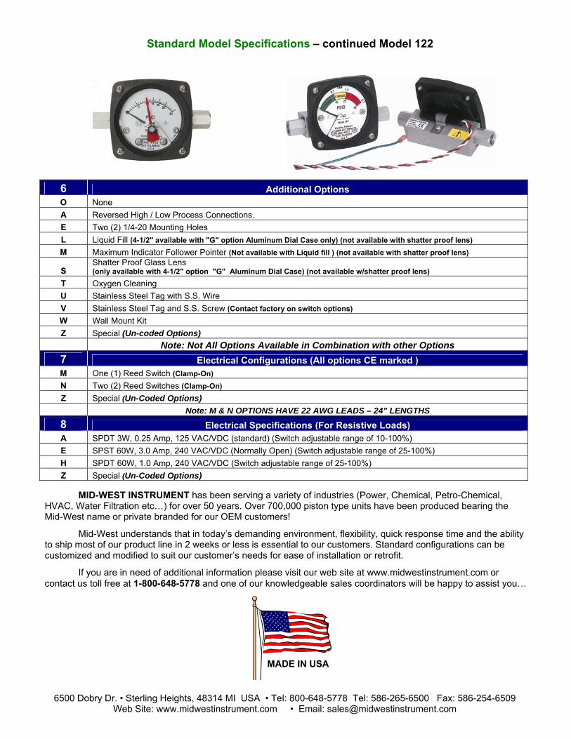
Standard Model Specifications – continued Model 120 6 Additional Options
O None A Reversed High / Low Process Connections. (Not available with Electrical options J & K) C Mounting Holes in Gauge Body for Field Mounting Electrical Configurations Options A & B D Mounting Holes in Gauge Body for Field Mounting Electrical Configurations Options L & M E Two (2) 1/4-20 Mounting Holes (not available with C, D, E or F electrical switch options) F Carbon Steel 2" Pipe Mounting Kit (not available with C, D, E or F electrical switch options) G Stainless Steel 2" Pipe Mounting Kit (not available with C, D, E or F electrical switch options) K 1/2" FNPT S.S. Adapter (not available with E or F switch option combined w/back connections) L Liquid Fill (4-1/2" available with "G" option Aluminum Dial Case only) (not available with shatterproof lens) M Maximum Indicator Follower Pointer (not available with Liquid fill option) (not available with shatterproof lens) N NACE (Available for Aluminum, Stainless Steel and Monel Gauge Bodies Only) Q CRN (Canadian Registration Number) Available on Aluminum or S.S. Body only S Shatter Proof Glass Lens (Available only with option “G” 4-1/2” Aluminum Dial Case) (not available with liquid fill) T Oxygen Cleaning U Stainless Steel Tag with S.S. Wire
V Stainless Steel Tag and S.S. Screw (Contact Factory on Switch Options) Not on Gauge Body for Hazardous Locations
W Wall Mount Kit (not available with back connections or with C, D, E or F switch options) Z Special (Un-coded Options) NOTE: Not All Options Available in Combination with other Options
7 Electrical Configurations (CE marked, except E, F, J & K) (6) A One (1) Switch in standard enclosure with grommet Wire Seal B Two (2) Switch in standard enclosures with grommet Wire Seal C One (1) Switch in standard enclosure with 1/4” FNPT electrical connection NEMA 4X D Two (2) Switch in standard enclosures with 1/4” FNPT electrical connection NEMA 4X E One (1) Switch in general purpose enclosure, Division 2 Hazardous Locations (1) (3) (4) (5) F Two (2) Switches in general purpose enclosure, Division 2 Hazardous Locations (1) (3) (4) (5) G One (1) Switch & gauge in NEMA 4X plastic enclosure (Not available with end connections) H Two (2) Switches & gauge in NEMA 4X plastic enclosure (Not available with end connections) J One (1) Switch in explosion proof enclosure w/glass window cover, Div. 1 Hazardous Locations (2) (3) (4) (5) K Two (2) Switches in explosion proof enclosure w/glass window cover, Div.1 Hazardous Locations (2) (3) (4) (5) L One (1) Switch in standard enclosure with plug-in connector (DIN 43650/IP65-PG11) M Two (2) Switch in standard enclosures with plug-in connector (DIN 43650/IP65-PG11) Z Special (Un-coded Options)
(1) Complete assembly 3rd Party Certified Class I, Div.2, Groups A, B, C, & D; Class II, Div.2, Groups F and G. (2) Complete assembly 3rd Party Certified Class I, Div.1, Groups C & D; Class II, Div. 1, Groups E, F, & G. (3) 5000 PSIG SWP for Stainless Steel: 3000 PSIG SWP for Aluminum (4) Not available in M and N material options (5) 1/2" FNPT conduit connection (6) Contact factory for Bi-directional scales with switches
8 Electrical Specifications (For Resistive Loads) A SPDT 3W, 0.25 Amp, 125 VAC/VDC (standard) (Switch adjustable range of 10-90%) E SPST 60W, 3.0 Amp, 240 VAC/VDC (Normally Open) (Switch adjustable range of 25-95%) F SPST 60W, 3.0 Amp, 240 VAC/VDC (Normally Closed) (Switch adjustable range of 25-95%)
G SPST 60W, 3.0 Amp, 240 VAC/VDC (1) Normally Open, (1) Normally Closed (Switch adjustable range of 25-95%)
H SPDT 60W, 1.0 Amp, 240 VAC/VDC (Switch adjustable range of 25-100%) Z Special (Un-coded Options)
If you are in need of additional information please visit our web site at www.midwestinstrument.com or contact us toll free at 1-800-648-5778 and one of our knowledgeable sales coordinators will be happy to assist you…
6500 Dobry Dr. • Sterling Heights, 48314 MI USA • Tel: 800-648-5778 Tel: 586-254-6500 Fax: 586-254-6509 Web Site: www.midwestinstrument.com • Email: [email protected]

Product Notes:Mid-West Instrument ®

Mid-West Instrument
BULLETIN NO. 120MALBZ/13
®
“Piston Type” Differential Pressure Gauge or Switch
Model 120
FOR SEA WATER APPLICATIONS
Ideally suited for use on Sea Water or salt Water applications.
Model 120 Shown With 2-1/2” Dial & Switch
•
Features: • Simple, rugged, compact design. • Working pressure 5,000 PSIG (340 bar) • Over-range protection to maximum pressure. • Over range protection to full rated working pressure. • Body Materials: Aluminum/Bronze, or Monel • ¼” FNPT FNPT End Connection (std) • Weather-resistant construction standard. • Shatter resistant acrylic lens. Variety of Dial type and Sizes: 2-1/2”, 3-1/2” & 4-1/2” • DP Ranges available in: Inches PSID, Bar, and Kpa • Temperature Limits: -40°F(-40°C) to +200°F(+93°C)
Due to precision sizing of piston and
body bore, leakage across piston will not exceed 15 SCFH air at 100 PSID at ambient temperature.
Model 120 shown with Customer colored Dial
Model 120 ShownWith 4-1/2” Dial
An optional maximum indication follower pointer provides automatic indication of maximum differential occurring during a time period or system cycle. Reversed pressure ports are optionally available to facilitate installation and readability depending on which side of a filter, etc., the instrument must be installed.
Model Accuracy Available ΔP Range
Max. Line Pressure
PSIG Optional Switches
120 ±5%
0-5 PSID, 0-10 PSID 0-15 PSID, 0-20 PSID 0-25 PSID, 0-30 PSID 0-50 PSID, 0-100 PSID 5,000
1 & 2 switch Hermetically Sealed

“Piston Type” Differential Pressure Gauge
Switch Options Model 120
1 & 2 Switch Examples shown
The Model 120 Series DP gauge is available with one or two hermetically sealed reed switches.
(See chart below)
The switches are adjustable (see table for adjustment range) within a defined percentage of the full scale range of the gauge and are available in SPDT and SPST, normally open or normally closed configurations for various load power ratings. The switches can be set to activate or deactivate on rising or falling pressure.
The standard reed switch is enclosed in a weather-resistant plastic housing. Adjustment of the switch
setting is made with an external screw adjustment.
The switch functionality will be different for gauges with bi-directional operation for positive and negative delta pressure. For example a SPDT switch with positive .P applied to the gauge, the red wire will be N.O. and the black will be N.C.. For negative .P the functionality will be reversed.
Location for a single SPDT (grommet or conduit) switch will be on the bottom of the gauge body for a normal port and on the top for a reverse port. Locations for a single SPST (grommet or conduit) N.O. or SPST N.C. switch will be on the bottom and top respectively for a normal port gauge. The locations will be reversed for a reverse port gauge. A non-indicating (no dial) differential pressure switch is also available.
Model Type 120 SPDT 120 SPDT 120
SPST NO 120
SPST NC 120 SPST
NO/NC
Power 3 W 60 W 60 W 60 W 60 W
Max Current 0.25 Amps 1.0 Amps 3.0 Amps 3.0 Amps 3.0 Amps Max Voltage VAC/VDC 125 240 240 240 240
Setting Full Scale 10-90% 25-100% 25-95% 25-95% 25-95% Hysterisis
(Max / Norm) 10% / 5% (FS) 20% / 13%
(FS) 15% / 8% (FS) 15% / 8% (FS) 15% / 8% (FS)
Repeatability 1% F.S. 1% F.S. 1% F.S. 1% F.S. 1% F.S.
Leads 22 Awg (3) 24" (3) 24" (2) 24" (2) 24" (2) 24"
6500 Dobry Dr. • Sterling Heights, MI 48314 USA • Tel: 800-648-5778 Tel: 586-254-6500 Fax: 586-254-6509
Web Site: www.midwestinstrument.com • Email: [email protected]

Standard Model Specifications: 120-NA-02-OO
5000 PSIG Working Pressure, Aluminum Bronze Body & Piston, Monel Spring, Ceramic Magnet, Buna-N Seals, ¼” FNPT End Connections,
2-1/2” round dial, Engineered Plastic Case with Shatter Resistant Acrylic Lens, Accuracy ±5% Full Scale (Ascending)
Ranges: 0-10 PSID, 0-15 PSID, 0-10 PSID, 0-25 PSID and 0-30 PSID
Mid-West Instrument 1-800-648-5778 Range:_________________
Basic Model
1 2 0
7 8 6 4 5 2 3 1
2 Material M Monel Body / Monel Piston N Aluminum Bronze Body / Aluminum Bronze Piston Z Special (Un-coded Options)
3 Dial Size & Type A 2-1/2" Round Uni-Directional Dial w/Engineered Plastic Dial Case C 4-1/2" Round Uni-Directional Dial w/Engineered Plastic Dial Case E 3-1/2" Round Uni-Directional Dial w/Anodized Aluminum Housing Dial Case G 4-1/2" Round Uni-Directional Dial w/Anodized Aluminum Housing Dial Case T Non-Indicating DP Switch Only Z Special (Un-coded Options)
4 Seal Materials 0 Buna-N (Standard) 1 Viton®-A Registered Trademark of Dupont 2 Neoprene 4 Teflon®-A Registered Trademark of Dupont 5 Ethylene Propylene 9 Special (Un-coded Options)
5 Process Connections 2 1/4" FNPT End Connections 9 Special (Un-coded Options)

Standard Model Specifications – continued Model 120
6 Additional Options O None A Reversed High / Low Process Connections. E Two (2) 1/4-20 Mounting Holes (not available with C or D electrical switch options) F Carbon Steel 2" Pipe Mounting Kit (not available with C or D electrical switch options) G Stainless Steel 2" Pipe Mounting Kit (not available with C or D electrical switch options) L Liquid Fill (4-1/2" available with "G" option Aluminum Dial Case only) (not available with shatterproof lens) M Maximum Indicator Follower Pointer (not available with Liquid fill option) (not available with shatterproof lens) S Shatter Proof Glass Lens (Available only with option “G” 4-1/2” Aluminum Dial Case) (not available with liquid fill) T Oxygen Cleaning U Stainless Steel Tag with S.S. Wire
V Stainless Steel Tag and S.S. Screw (Contact Factory on Switch Options) Not on Gauge Body for Hazardous Locations
W Wall Mount Kit (not available with C or D switch options) Z Special (Un-coded Options) NOTE: Not All Options Available in Combination with other Options
7 Electrical Configurations (CE marked) (6) A One (1) Switch in standard enclosure with grommet Wire Seal B Two (2) Switch in standard enclosures with grommet Wire Seal C One (1) Switch in standard enclosure with 1/4” FNPT electrical connection NEMA 4X D Two (2) Switch in standard enclosures with 1/4” FNPT electrical connection NEMA 4X L One (1) Switch in standard enclosure with plug-in connector (DIN 43650/IP65-PG11) M Two (2) Switch in standard enclosures with plug-in connector (DIN 43650/IP65-PG11) Z Special (Un-coded Options)
(6) Contact factory for Bi-directional scales with switches
8 Electrical Specifications (For Resistive Loads) A SPDT 3W, 0.25 Amp, 125 VAC/VDC (standard) (Switch adjustable range of 10-90%) E SPST 60W, 3.0 Amp, 240 VAC/VDC (Normally Open) (Switch adjustable range of 25-95%) F SPST 60W, 3.0 Amp, 240 VAC/VDC (Normally Closed) (Switch adjustable range of 25-95%)
G SPST 60W, 3.0 Amp, 240 VAC/VDC (1) Normally Open, (1) Normally Closed (Switch adjustable range of 25-95%)
H SPDT 60W, 1.0 Amp, 240 VAC/VDC (Switch adjustable range of 25-100%) Z Special (Un-coded Options)
Factory preset switches at no charge (Specify Setting)
MID-WEST INSTRUMENT has been serving a variety of industries (Power, Chemical, Petro-Chemical, HVAC, Water Filtration etc…) for over 50 years. Over 700,000 piston type units have been produced bearing the Mid-West name or private branded for our OEM customers!
Mid-West understands that in today’s demanding environment, flexibility, quick response time and the ability to ship product in 2 weeks or less is essential to our customers. Standard configurations can be customized and modified to suit our customer’s needs for ease of installation or retrofit.
If you are in need of additional information please visit our web site at www.midwestinstrument.com or contact us toll free at 1-800-648-5778 and one of our knowledgeable sales coordinators will be happy to assist you…
6500 Dobry Dr. • Sterling Heights, 48314 MI USA • Tel: 800-648-5778 Tel: 586-254-6500 Fax: 586-254-6509 Web Site: www.midwestinstrument.com • Email: [email protected]

Mid-West Instrument BULLETIN NO. 121/11
(SUPERSEDES BULLETIN NO. 121/06)
“Piston Type” Model 121 Differential Pressure Switch & Transmitter
®
A low cost differential pressure indicating switch or transmitter for use in measuring the pressure drop
across filters, strainers, separators, valves, pumps, chillers etc., and for local flow indication and control.
• cover and terminal strip •
to provide high and low limit alarm or control or 4-20mA transmitter.
• with 316 stainless steel internals. • • •
•
•
•
½ NPT conduit connection with heavy duty Switch or Transmitter
Choice of 1 or 2 magnetically actuated hermetically sealed reed switches
• Transmitter accuracy ± 2% full scale (from 20% to 100% of scale, ascending) Body materials: Aluminum or 316L Stainless Steel
Weather-resistant construction standard. Working pressure up to 6,000 PSIG (400 bar) Over-range protection to maximum pressure. Shatter resistant acrylic lens. Variety of Dial type and Sizes: 2-1/2”, 3-1/2” & 4-1/2” • Available DP Ranges: Inches H2O, PSID, bar, and Kpa Temperature Limits:
-40°F (-40°C) to +200°F (+93°C) (Switch Options) -20° F to + 150° F (Transmitter Option)
Transmitter now CSA Listed for
Division 2 Hazardous Location Service
Model 121 0-75 PSID
2-1/2” Dial. Shown with End Connections & Transmitter
Model 121 Switch ¼” FNPT back connections
Model Body
Material Gauge
Accuracy Min. ΔP Range
Max. ΔP Range
MWP PSIG (Bar) Switch Options
121 Aluminum & 316L S.S. ±3/2/3%
0-5 PSID (0-0.35 bar)
0-100 PSID (0-7 bar)
ALM. = 3,000 (200) S.S. = 6,000 (400)
1 or 2 switches or 4-20mA Transmitter
Model 121 0-50 PSID 4-1/2” Dial
& Transmitter
Model 121 Indicating Switch(es) or 4-20mA Transmitter SPECIFICATIONS
TRANSMITTER SWITCHES Features: Features: Microprocessor based, external zero interface: 1 or 2 hermetically sealed reed switches 8-28 Vdc loop powered, 2 wire interface Electrical: Electrical: Accuracy ±2% (from 20% to 100% of scale, ascending) 0-3W, 25 Amp Supply Voltage 8-28 Vdc 125 VAC (Adjustable 15-95% F.S.) Output 4-20mA 60W, 3.0 Amp Max Loop Resistance 1000 Ohms 240 VAC (Adjustable 20-95% F.S.) Interface: Interface: 4 position terminal strip for 16-22 Awg wire 7 position terminal strip for 16-22 Awg wire Pin 1 – return, Pin 2 = zero, Pin 3 = 8-28 Vdc, Pin 4-chassis 1/2“ NPT conduit connection 1/2” NPT conduit connection Environmental: Weatherproof Environmental: Weatherproof Rating: (NEMA 4X, IP65) Rating: (NEMA 4X, IP65)

“Piston Type” Differential Pressure
Switch & Transmitter Options Model 121
Open back view Model 121 reed switch
with terminal strip
Open view Model 121 Transmitter 4-20 mA terminal strip
w/ ¼” FNPT end connections Model 121 Transmitter show with NEMA 4X plastic cover
Piston-Type Differential Pressure Gauges are available with one or two hermetically sealed reed switches. The switches are adjustable within a defined percentage of the full scale range of the gauge and are available in SPDT and SPST, normally open or normally closed configurations for various load/power ratings. The switches can be set to activate or deactivate on rising or falling pressure. Switches are "CE" marked per the EU low voltage directive. Models 121 can be configured for use in Hazardous Locations.
Piston Type DP Gauge: ± 2% Full Scale Accuracy. They are primarily designed for liquid applications. They exhibit a slight amount of bypass as the fluid crosses from the high to the low pressure port. Because gas molecules are smaller, the crossover is often deemed too great for the application. Due to precision sizing of piston and body bore, leakage across the piston will not exceed 15 SCFH air at 100 PSID at ambient conditions.
Available Electrical Configurations One (1) Reed switch in NEMA 4X/IP65 Plastic enclosure with terminal strip (1/2” FNPT Conduit Connection) Two (2) Reed switches in NEMA 4X/IP65 Plastic enclosure with terminal strip (1/2” FNPT Conduit Connection) One (1) Switch in general purpose enclosure, Division 2 Hazardous Locations (1) (2) Two (2) Switches in general purpose enclosure, Division 2 Hazardous Locations (1) (2) 4-20 mA Transmitter in NEMA 4X/IP65 Plastic enclosure with terminal strip (1/2” FNPT Conduit Connection) (3) 4-20 mA Transmitter in NEMA 4X/IP65 Plastic enclosure. Division 2 Hazardous Locations with terminal strip (1/2” FNPT Conduit Connection) (1) (2) (3)
(1) Complete assembly 3rd Party Certified Class I, Div.2, Groups A, B, C, & D; Class II, Div.2, Groups F and G. (2) 5000 PSIG SWP for Stainless Steel: 3000 PSIG SWP for Aluminum (3) Contact factory for flow applications with transmitter configuration Available Electrical Specifications (For Resistive Loads)
SPDT 3W, 0.25 Amp, 125 VAC/VDC (standard) (Switch adjustable range of 15-95%) SPST 60W, 3.0 Amp, 240 VAC/VDC (Normally Open) (Switch adjustable range of 20-95%) SPST 60W, 3.0 Amp, 240 VAC/VDC (Normally Closed) (Switch adjustable range of 20-95%) SPST 60W, 3.0 Amp, 240 VAC/VDC (1) Normally Open, (1) Normally Closed (Switch adjustable range of 20-95%) 4-20 mA Transmitter (8-28 VDC Loop Power) ( ±2% accuracy from 20% to 100% of scale. Ascending)
Proof Pressure: Two times rated working pressure at ambient temperature.
Temperature Limits: Switch Options: -40°F to + 200°F Transmitter Options: -20° F TO + 150° F These limits are based on the entire instrument being saturated to these temperatures. System (process) temperatures may exceed these limitations with proper installation. Contact our customer service representative for details. Standards: Model 121 Gauge either conforms to and/or is designed to the requirements of the following standards: ASME B1.20.1 NACE MR0175 ASME B40.100 NEMA Std. No. 250 CSA-C22.2 No. 14.25 and 30 SAE J514 EN-61010-1 UL Std. No. 50,508 and 1203
6500 Dobry Dr. • Sterling Heights, MI 48314 USA • Tel: 800-648-5778 Tel: 586-254-6500 Fax: 586-254-6509 Web Site: www.midwestinstrument.com • Email: [email protected]

® Mid-West Instrument Standard Dial Ranges: Model 121
The above mentioned ranges are some of the most popular requested today. Mid-West Instrument can provide special un-cataloged dial range requirements. As well as multiple scale dials, multiple color dials and special decals. Please consult factory for complete information.
Model Min. ΔP Range Max. ΔP Range
121 0-5 PSID (0-0.35 bar) 0-100 PSID (0-7 bar)
Range Type PSID Kpa Bar
0-5 PSID 0-100 Kpa 0-1.0 Bar 0-10 PSID 0-160 Kpa 0-1.6 Bar 0-15 PSID 0-250 kpa 0-2.0 Bar 0-20 PSID 0-400 Kpa 0-2.5 Bar 0-25 PSID 0-600 Kpa 0-4.0 Bar 0-30 PSID 0-700 Kpa 0-6.0 Bar 0-50 PSID 0-7.0 Bar 0-60 PSID 0-75 PSID 0-100 PSID
Proof Pressure: Two times rated working pressure at ambient temperature.
Temperature Limits: Switch Options: -40°F to + 200°F Transmitter Options: -20° F TO + 150° F These limits are based on the entire instrument being saturated to these temperatures. System (process) temperatures may exceed these limitations with proper installation. Contact our customer service representative for details. Standards: Model 121 Gauge either conforms to and/or is designed to the requirements of the following standards: ASME B1.20.1 NACE MR0175 ASME B40.100 NEMA Std. No. 250 CSA-C22.2 No. 14.25 and 30 SAE J514 EN-61010-1 UL Std. No. 50,508 and 1203

Standard Model Specifications: 121-AA-00-O(TT) 3000 PSIG Working Pressure, Aluminum Body, Adjusting Screws & End Plugs, Stainless Steel Piston,
Ceramic Magnet, Buna-N Seals, ¼” FNPT Back Connections, 2-1/2” round dial, Engineered Plastic Case with Shatter Resistant Acrylic Lens,
4-20mA, 8-28 VDC Loop powered Transmitter in NEMA 4X/IP65 Plastic enclosure with terminal strip, & ½” FNPT Conduit Connection, Accuracy ±3/2/3% Full Scale (Ascending)
Range 0-5 PSID to 0-100PSID (0-.35 bar to 0-7.0 bar) Mid-West Instrument 1-800-648-5778
Range:_________________
Basic Model
1 2 1
7 8 6 4 5 2 3 1
2 Material A Aluminum Body / Stainless Steel Piston S 316 S.S Body / Stainless Steel Piston Z Special (Un-coded Options)
3 Dial Size & Type A 2-1/2" Round Uni-Directional Dial w/Engineered Plastic Dial Case C 4-1/2" Round Uni-Directional Dial w/Engineered Plastic Dial Case E 3-1/2" Round Uni-Directional Dial w/Anodized Aluminum Housing Dial Case G 4-1/2" Round Uni-Directional Dial w/Anodized Aluminum Housing Dial Case T Non-Indicating DP Switch Only Z Special (Un-coded Options)
4 Seal Materials 0 Buna-N (Standard) 1 Viton®-A Registered Trademark of Dupont 2 Neoprene 4 Teflon®-A Registered Trademark of Dupont 5 Ethylene Propylene 6 Perfluorelastomers 9 Special (Un-coded Options)
5 Process Connections 0 1/4" FNPT Back Connections (Standard) 2 1/4" FNPT End Connections 3 1/4" FNPT Bottom Connections 4 1/2" FNPT End Connections 6 7/16"-20 Straight Thread "O" Ring Port (Back Connection) 9 Special (Un-coded Options)
Factory preset switches at no charge (Specify Setting)

Standard Model Specifications – continued Model 121
6 Additional Options O None F Carbon Steel 2" Pipe Mounting Kit G Stainless Steel 2" Pipe Mounting Kit K 1/2" FNPT Stainless Steel Adapter L Liquid Fill (4-1/2" available with "G" option Aluminum Dial Case only) (not available with shatterproof lens) M Maximum Indicator Follower Pointer (Not available with Liquid fill option) (not available with shatterproof lens) N NACE Q CRN (Canadian Registration Number) (2) S Shatter Proof Glass Lens (Available only with 4-1/2” Aluminum Dial Case) (not available with liquid fill) T Oxygen Cleaning U Stainless Steel Tag with S.S. Wire W Wall Mount Kit (Not available with back connections) Z Special (Un-coded Options)
7 Electrical Configurations A One (1) Reed switch in NEMA 4X/IP65 Plastic enclosure with terminal strip (1/2” FNPT Conduit Connection) B Two (2) Reed switches in NEMA 4X/IP65 Plastic enclosure with terminal strip (1/2” FNPT Conduit Connection) E One (1) Switch in general purpose enclosure, Division 2 Hazardous Locations (1) (2) F Two (2) Switches in general purpose enclosure, Division 2 Hazardous Locations (1) (2)
4-20 mA Transmitter in NEMA 4X/IP65 Plastic enclosure with terminal strip T (1/2” FNPT Conduit Connection) (3)
4-20 mA Transmitter in NEMA 4X/IP65 Plastic enclosure. Division 2 Hazardous Locations with terminal strip W (1/2” FNPT Conduit Connection) (1) (2) (3) Z Special (Un-coded Options)
(1) Complete assembly 3rd Party Certified Class I, Div.2, Groups A, B, C, & D; Class II, Div.2, Groups F and G. (2) 5000 PSIG SWP for Stainless Steel: 3000 PSIG SWP for Aluminum (3) Contact factory for flow applications with transmitter configuration
8 Electrical Specifications (For Resistive Loads) A SPDT 3W, 0.25 Amp, 125 VAC/VDC (standard) (Switch adjustable range of 15-95%) E SPST 60W, 3.0 Amp, 240 VAC/VDC (Normally Open) (Switch adjustable range of 20-95%) F SPST 60W, 3.0 Amp, 240 VAC/VDC (Normally Closed) (Switch adjustable range of 20-95%)
SPDT 60W, 3.0 Amp, 240 VAC/VDC G (1) Normally Open, (1) Normally Closed (Switch adjustable range of 20-95%) T 4-20 mA Transmitter (8-28 VDC Loop Power) ( ±2% accuracy from 20% to 100% of scale. Ascending) Z Special (Un-coded Options)
MID-WEST INSTRUMENT has been serving a variety of industries (Power, Chemical, Petro-Chemical, HVAC, Water Filtration etc…) for over 50 years. Over 700,000 piston type units have been produced bearing the Mid-West name or private branded for our OEM customers!
Mid-West understands that in today’s demanding environment, flexibility, quick response time and the ability to ship product in 2 weeks or less is essential to our customers. Standard configurations can be customized and modified to suit our customer’s needs for ease of installation or retrofit.
If you are in need of additional information please visit our web site at www.midwestinstrument.com or contact us toll free at 1-800-648-5778 and one of our knowledgeable sales coordinators will be happy to assist you…
6500 Dobry Dr. • Sterling Heights, 48314 MI USA • Tel: 800-648-5778 Tel: 586-254-6500 Fax: 586-254-6509 Web Site: www.midwestinstrument.com • Email: [email protected]

Product Notes:Mid-West Instrument ®

Mid-West Instrument BULLETIN NO. 122/11
(SUPERSEDES BULLETIN NO. 122/01)
“Piston Type” Differential Pressure Gauges
Switches & Transmitters Model 122
®
A low cost differential pressure gauge for use in measuring the pressure drop across filters, strainers, separators, valves, pumps, chillers, etc., and for local flow indication and control.
Model 122 With Special 3 color dial
• Simple, rugged, compact design. • Working pressure up to 3,000 PSIG (200 bar) • Over-range protection to maximum pressure. • Body material: Aluminum with 316 stainless steel internals. • Weather-resistant construction standard. • Shatter resistant acrylic lens. • Variety of Dial type and Sizes: 2-1/2”, 3-1/2” & 4-1/2” • Available DP Ranges: Inches H2O, PSID, bar, and Kpa • ¼” FNPT End Process Connections • Panel Mountable, Wall mount available as option • Temperature Limits: -40°F(-40°C) to +200°F(+93°C)
Due to precision sizing of piston and body bore, leakage across piston will not exceed 15 SCFH air at 100 PSID at ambient temperature.
Model 122 0-50 PSID 4-1/2” Dial
Model 122 0-15 PSID
An optional maximum indication follower pointer provides automatic indication of maximum differential occurring during a time period or system cycle. Reversed pressure ports are optionally available to facilitate installation and readability depending on which side of a filter, etc., the instrument must be installed.
Model 122 0-30 PSID 2-1/2” Dial w/Maximum
Follower Pointer
Model Body Material Accuracy Min. ΔP Range Max. ΔP Range
MWP PSIG (Bar) Switch Options
122 Aluminum ±5% 0-5 PSID (0-0.35 bar) 0-110 PSID
(0-7 bar) 3,000 (200) 1 & 2 switch
Hermetically Sealed
Proof Pressure: Two times rated working pressure at ambient temperature
Standards: Model 122 gauge either conforms to and/or is designed to the requirements of the following standards: ASME B1.20.1 NACE MR0175 ASME B40.100 NEMA Std. No. 250 CSA-C22.2 No. 14.25 and 30 SAE J514 EN-61010-1 UL Std. No. 50,508 and 1203

“Piston Type” Differential Pressure Gauge
Switch Option Model 122
Model 122 Gauge with switches have one or two Single Pole Single Throw (SPST) or Single Pole Double Throw (SPDT) reed switches with the resistive ratings specified in the table below.
A provision to connect a protective conductor terminal is provided on the Low port end of the gauge body. A 6-32 screw, 18 Awg, green/yellow wire, and a #6 terminal is provided.
Note: Switches can be set below the defined minimum set point how ever the switch may not remain activated at maximum PSID. If the unit is set below the defined minimum set point, the customer should verify that the switch remains activated from the set point to over range of the gauge.
Provide standard protection techniques for the switch contacts for capacitive and inductive loads. Use current limiting techniques near the switch to protect the contacts due to high inrush (i.e.; in line resistor or inductor) for long cable interfaces. Provide clamping devices at or near inductive loads (i.e.; relay).
Maximum wire length between the 3W switch and its load should not exceed 70 – 100 feet or 120 VAC applications. Contact the factory for assistance regarding this condition.
WARNING: Electrical connections should be performed by qualified personnel and meet representative national electrical code.
WARNING: Failure to connect to the protective conductor terminal may result in a shock hazard.
REED SWITCH RATINGS (Resistive Load)
Type SPDT SPST NO SPDT
Option A E H
Power 3 W 60 W 60 W
Max Current 0.25
Amps 3.0 Amps 1.0 Amps Max Voltage
VAC/VDC 125 240 240 Setting
Full Scale 10-100% 25-100% 25-100% Hysterisis
(Max / Norm) 10% / 5%
(FS) 15% / 8%
(FS) 25% / 13%
(FS)
Repeatability 1% F.S. 1% F.S. 1% F.S.
Leads 22 Awg (3) 24" (2) 24" (3) 24"
Temperature Limits: -40°F (-40°C) to +200°F (+93°C) These limits are based on the entire instrument being saturated to these temperatures. System (process) temperatures may exceed these limitations
6500 Dobry Dr. • Sterling Heights, MI 48314 USA • Tel: 800-648-5778 Tel: 586-254-6500 Fax: 586-254-6509 Web Site: www.midwestinstrument.com • Email: [email protected]

Standard Dial Ranges: Model 120, 122, 123, 124
® Mid-West Instrument
The above mentioned ranges are some of the most popular requested today. Mid-West Instrument can provide special un-cataloged dial range requirements. As well as multiple scale dials, multiple color dials and special decals. Please consult factory for complete information.
Model Min. ΔP Range Max. ΔP Range 120 0-5 PSID (0-0.35 bar) 0-110 PSID (0-7 bar) 122 0-5 PSID (0-0.35 bar) 0-100 PSID (0-7 bar)
**123 0-150 PSID (0-10 bar) 0-400 PSID (0-27.0 bar)
**124 0-5 PSID (0-0.35 bar) 0-150 PSID (0-10 bar)
0-110 PSID (0-7 bar) 0-400 PSID (0-27.0 bar)
Range Type PSID Kpa Bar Dual Scale
0-5 PSID 0-35 Kpa 0-1.0 Bar 0-5 PSID & 0-0.35 Kg/Cm2 0-10 PSID 0-70 Kpa 0-1.6 Bar 0-5 PSID & 0-35 KPA 0-15 PSID 0-100 Kpa 0-2.0 Bar 0-10 PSID & 0-0.7 BAR 0-20 PSID 0-160 Kpa 0-2.5 Bar 0-10 PSID & 0-0.7 KG/CM2 0-25 PSID 0-250 kpa 0-4.0 Bar 0-10 PSID & 0-70 KPA 0-30 PSID 0-400 Kpa 0-6.0 Bar 0-100 PSID & 0-7 BAR 0-50 PSID 0-600 Kpa 0-7.0 Bar 0-100 PSID & 0-7 KG/CM2 0-60 PSID 0-700 Kpa 0-100 PSID & 0-700 KPA 0-75 PSID 0-15 PSID & 0-1 BAR 0-100 PSID 0-15 PSID & 0-1 KG/CM2 0-110 PSID 0-15 PSID & 0-100 KPA **0-150 PSID 0-20 PSID & 0-1.4 BAR **0-200 PSID 0-20 PSID & 0-140 KPA **0-250 PSID 0-25 PSID & 0-1.75 BAR **0-300 PSID 0-25 PSID & 0-1.75 KG/CM2 **0-400PSID 0-25 PSID & 0-175 KPA 0-30 PSID & 0-2 BAR Bi-Directional Bi-Directional Bi-Directional 0-30 PSID & 0-2 KG/CM2 5-0-5 PSID 40-0-40 Kpa 0.4-0-0.4 Bar 0-30 PSID & 0-200 KPA 10-0-10 PSID 60-0-60 Kpa 0.6-0-0.6 Bar 0-50 PSID & 0-3.5 BAR 15-0-15 PSID 100-0-100 Kpa 1-0-1 Bar 0-50 PSID & 0-3.5 KG/CM2 20-0-20 PSID 160-0-160 Kpa 1.6-0-1.6 Bar 0-50 PSID & 0-350 KPA 25-0-25 PSID 250-0-250 Kpa 2.5-0-2.5 Bar 0-75 PSID & 0-500 KPA 30-0-30 PSID 400-0-400 Kpa 4-0-4 Bar 50-0-50 PSID 600-600 Kpa 6-0-6 Bar 60-0-60 PSID 100-0-100 PSID
Bi-Directional ranges available for Model 120 4-1/2” Dials only.
Proof Pressure: Two times rated working pressure at ambient temperature
Temperature Limits: -40°F(-40°C) to +200°F(+93°C) Transmitter Option: -20°F(-28°C) to +150°F(+65°C) These limits are based on the entire instrument being saturated to these temperatures. System (process) temperatures may exceed these limitations with proper installation. Contact our customer service representative for details.
Standards: Model 120 -124 Series gauges either conform to and/or are designed to the requirements of the following standards: ASME B1.20.1 NACE MR0175 ASME B40.100 NEMA Std. No. 250 CSA-C22.2 No. 14.25 and 30 SAE J514 EN-61010-1 UL Std. No. 50,508 and 1203

Standard Model Specification: 122-AA-02-OO
3000 PSIG Working Pressure, Aluminum Body, Stainless Steel Piston, Ceramic Magnet, Buna-N Seals, ¼” FNPT End Connections, 2-1/2” round dial, Engineered Plastic Case with Shatter Resistant Acrylic Lens,
Accuracy ±5% Full Scale (Ascending)
Range: 0-5 PSID to 0-100 PSID (0-.35 bar to 0-7.0 bar) Mid-West Instrument
1-800-648-5778
Range:_________________ Basic Model
1 2 2
7 8 6 4 5 2 3 1
2 Material A Aluminum Body / Stainless Steel Piston Z Special (Un-coded Options)
3 Dial Size & Type A 2-1/2" Round Uni-Directional Dial w/Engineered Plastic Dial Case C 4-1/2" Round Uni-Directional Dial w/Engineered Plastic Dial Case E 3-1/2" Round Uni-Directional Dial w/Anodized Aluminum Housing Dial Case G 4-1/2" Round Uni-Directional Dial w/Anodized Aluminum Housing Dial Case T Non-Indicating DP Switch Only Z Special (Un-coded Options)
4 Seal Materials 0 Buna-N (Standard) 1 Viton®-A Registered Trademark of Dupont 2 Neoprene 4 Teflon®-A Registered Trademark of Dupont 5 Ethylene Propylene 9 Special (Un-coded Options)
5 Process Connections 2 1/4" FNPT End Connections (Standard) 9 Special (Un-coded Options)
Factory preset switches at no charge (Specify Setting)
Standard Model Specifications – continued Model 122
6 Additional Options O None A Reversed High / Low Process Connections. E Two (2) 1/4-20 Mounting Holes L Liquid Fill (4-1/2" available with "G" option Aluminum Dial Case only) (not available with shatter proof lens) M Maximum Indicator Follower Pointer (Not available with Liquid fill ) (not available with shatter proof lens)
S Shatter Proof Glass Lens (only available with 4-1/2" option "G" Aluminum Dial Case) (not available w/shatter proof lens)
T Oxygen Cleaning U Stainless Steel Tag with S.S. Wire V Stainless Steel Tag and S.S. Screw (Contact factory on switch options) W Wall Mount Kit Z Special (Un-coded Options) Note: Not All Options Available in Combination with other Options 7 Electrical Configurations (All options CE marked ) M One (1) Reed Switch (Clamp-On) N Two (2) Reed Switches (Clamp-On) Z Special (Un-Coded Options) Note: M & N OPTIONS HAVE 22 AWG LEADS – 24” LENGTHS
8 Electrical Specifications (For Resistive Loads) A SPDT 3W, 0.25 Amp, 125 VAC/VDC (standard) (Switch adjustable range of 10-100%) E SPST 60W, 3.0 Amp, 240 VAC/VDC (Normally Open) (Switch adjustable range of 25-100%) H SPDT 60W, 1.0 Amp, 240 VAC/VDC (Switch adjustable range of 25-100%) Z Special (Un-Coded Options)
MID-WEST INSTRUMENT has been serving a variety of industries (Power, Chemical, Petro-Chemical, HVAC, Water Filtration etc…) for over 50 years. Over 700,000 piston type units have been produced bearing the Mid-West name or private branded for our OEM customers!
Mid-West understands that in today’s demanding environment, flexibility, quick response time and the ability to ship most of our product line in 2 weeks or less is essential to our customers. Standard configurations can be customized and modified to suit our customer’s needs for ease of installation or retrofit.
If you are in need of additional information please visit our web site at www.midwestinstrument.com or contact us toll free at 1-800-648-5778 and one of our knowledgeable sales coordinators will be happy to assist you…
MADE IN USA
6500 Dobry Dr. • Sterling Heights, 48314 MI USA • Tel: 800-648-5778 Tel: 586-265-6500 Fax: 586-254-6509 Web Site: www.midwestinstrument.com • Email: [email protected]

Product Notes:Mid-West Instrument ®

Mid-West Instrument
BULLETIN NO. 123/11 (SUPERSEDES BULLETIN NO. 123/03)
®
“Piston Type” Differential Pressure Gauges
Switches & Transmitters Model 123
A low cost differential pressure gauge for use in measuring the pressure drop across filters, strainers, separators, valves, pumps, chillers, etc., and for local flow indication and control.
Model 123 0-400 PSID 2-1/2” Dial
• Simple, rugged, compact design. • Working pressure up to 5,000 PSIG (340 bar) • Over-range protection to maximum pressure. • Body materials: Aluminum or 316L Stainless Steel with 316 stainless steel internals. • Weather-resistant construction standard. • Shatter resistant acrylic lens. • Variety of Dial type and Sizes: 2-1/2”, 3-1/2”, & 4-1/2” • Available DP Ranges: Inches H2O, PSID, bar, and Kpa • ¼” FNPT & ½” FNPT Process Connections • Multiple mounting options available • Temperature Limits: -40°F(-40°C) to +200°F(+93°C)
Due to precision sizing of piston and body bore, leakage across piston will not exceed 15 SCFH air at 100 PSID at ambient temperature.
Model 123 0-300 PSID 4-1/2” Dial Model 123 0-400 PSID
Shown with 2 Std. Switches
An optional maximum indication follower pointer provides automatic indication of maximum differential occurring during a time period or system cycle. Reversed pressure ports are optionally available to facilitate installation and readability depending on which side of a filter, etc., the instrument must be installed.
Model Body Material Accuracy Min. ΔP Range Max. ΔP Range MWP PSIG (Bar) Switch Options
123 Aluminum & 316L S.S. ±3/2/3%
0-150 PSID (0-10 bar)
0-400 PSID (0-27 bar)
ALM. = 3,000 (200) S.S. = 5,000 (340)
1 & 2 switch Hermetically Sealed
Proof Pressure: Two times rated working pressure at ambient temperature
Standards: Model 123 gauge either conforms to and / or is designed to the requirements of the following standards: ASME B1.20.1 NACE MR0175 ASME B40.100 NEMA Std. No. 250 CSA-C22.2 No. 14.25 and 30 SAE J514 EN-61010-1 UL Std. No. 50,508 and 1203

“Piston Type” Differential Pressure Gauge
Switch & Transmitter Options Models 120, 122, 123 & 124
The Model 120-124 Series DP gauges are available with one or two hermetically sealed reed switches or 4-20mA transmitter depending on model. (See chart below)
The switches are adjustable (see table for adjustment range) within a defined percentage of the full scale range of the gauge and are available in SPDT and SPST, normally open or normally closed configurations for various load power ratings. The switches can be set to activate or deactivate on rising or falling pressure.
The standard reed switch is enclosed in a weather-resistant plastic housing. Adjustment of the switch setting is made with an external screw adjustment.
The switch functionality will be different for gauges with bi-directional operation for positive and negative delta pressure. For example a SPDT switch with positive .P applied to the gauge, the red wire will be N.O. and the black will be N.C.. For negative .P the functionality will be reversed.
Location for a single SPDT (grommet or conduit) switch will be on the bottom of the gauge body for a normal port and on the top for a reverse port. Locations for a single SPST (grommet or conduit) N.O. or SPST N.C. switch will be on the bottom and top respectively for a normal port gauge. The locations will be reversed for a reverse port gauge. A non-indicating (no dial) differential pressure switch is also available.
Hazardous Location switches are 3rd Party Certified Class I Div 2 or Class I Div 1 dependant on type of switch. Listings are for the entire design and not just the enclosure. Standard and weatherproof units are CE marked for conformance with the Low Voltage Directive to harmonized standard EN 61010-1.
Transmitters feature Microprocessor based, external zero interface, 8-28 Vdc loop powered, 2 wire interface. Standard output of 4-20mA with a max loop resistance of 1000 Ohms.
Model
•120, ^122,+123,
+124 •120,^122,
•123,
•120, ^122,+123,
+124 •120,
•123,•124 •120,
•123,•124 121, 124 Type SPDT SPDT SPST NO SPST NC SPST NO/NC 4-20mA Power 3 W 60 W 60 W 60 W 60 W 4-20 mA Loop Power
Max Current 0.25 Amps 1.0 Amps 3.0 Amps 3.0 Amps 3.0 Amps
8-28 VDC Loop Powered
2-Wire interface Max Voltage VAC/VDC 125 240 240 240 240
1000 Ohm max Loop resistance at 28 vdc
•10-90% •25-100% •25-95%
^10-100% ^25-100% ^25-100% Setting Full Scale +15-90% +25-95% •25-95% •25-95% 20-100% Hysterisis
(Max / Norm) 10% / 5% (FS) 20% / 13% (FS) 15% / 8% (FS) 15% / 8% (FS) 15% / 8% (FS) N/A
Repeatability 1% F.S. 1% F.S. 1% F.S. 1% F.S. 1% F.S. 1% F.S
Leads 22 Awg (3) 24" (3) 24" (2) 24" (2) 24" (2) 24" N/A
6500 Dobry Dr. • Sterling Heights, MI 48314 USA • Tel: 800-648-5778 Tel: 586-254-6500 Fax: 586-254-6509
Web Site: www.midwestinstrument.com • Email: [email protected]

Standard Dial Ranges: Model 120, 122, 123, 124
® Mid-West Instrument
The above mentioned ranges are some of the most popular requested today. Mid-West Instrument can provide special un-cataloged dial range requirements. As well as multiple scale dials, multiple color dials and special decals. Please consult factory for complete information.
Model Min. ΔP Range Max. ΔP Range 120 0-5 PSID (0-0.35 bar) 0-110 PSID (0-7 bar) 122 0-5 PSID (0-0.35 bar) 0-100 PSID (0-7 bar)
**123 0-150 PSID (0-10 bar) 0-400 PSID (0-27.0 bar)
**124 0-5 PSID (0-0.35 bar) 0-150 PSID (0-10 bar)
0-110 PSID (0-7 bar) 0-400 PSID (0-27.0 bar)
Range Type PSID Kpa Bar Dual Scale
0-5 PSID 0-35 Kpa 0-1.0 Bar 0-5 PSID & 0-0.35 Kg/Cm2 0-10 PSID 0-70 Kpa 0-1.6 Bar 0-5 PSID & 0-35 KPA 0-15 PSID 0-100 Kpa 0-2.0 Bar 0-10 PSID & 0-0.7 BAR 0-20 PSID 0-160 Kpa 0-2.5 Bar 0-10 PSID & 0-0.7 KG/CM2 0-25 PSID 0-250 kpa 0-4.0 Bar 0-10 PSID & 0-70 KPA 0-30 PSID 0-400 Kpa 0-6.0 Bar 0-100 PSID & 0-7 BAR 0-50 PSID 0-600 Kpa 0-7.0 Bar 0-100 PSID & 0-7 KG/CM2 0-60 PSID 0-700 Kpa 0-100 PSID & 0-700 KPA 0-75 PSID 0-15 PSID & 0-1 BAR 0-100 PSID 0-15 PSID & 0-1 KG/CM2 0-110 PSID 0-15 PSID & 0-100 KPA **0-150 PSID 0-20 PSID & 0-1.4 BAR **0-200 PSID 0-20 PSID & 0-140 KPA **0-250 PSID 0-25 PSID & 0-1.75 BAR **0-300 PSID 0-25 PSID & 0-1.75 KG/CM2 **0-400PSID 0-25 PSID & 0-175 KPA 0-30 PSID & 0-2 BAR Bi-Directional Bi-Directional Bi-Directional 0-30 PSID & 0-2 KG/CM2 5-0-5 PSID 40-0-40 Kpa 0.4-0-0.4 Bar 0-30 PSID & 0-200 KPA 10-0-10 PSID 60-0-60 Kpa 0.6-0-0.6 Bar 0-50 PSID & 0-3.5 BAR 15-0-15 PSID 100-0-100 Kpa 1-0-1 Bar 0-50 PSID & 0-3.5 KG/CM2 20-0-20 PSID 160-0-160 Kpa 1.6-0-1.6 Bar 0-50 PSID & 0-350 KPA 25-0-25 PSID 250-0-250 Kpa 2.5-0-2.5 Bar 0-75 PSID & 0-500 KPA 30-0-30 PSID 400-0-400 Kpa 4-0-4 Bar 50-0-50 PSID 600-600 Kpa 6-0-6 Bar 60-0-60 PSID 100-0-100 PSID
Bi-Directional ranges available for Model 120 4-1/2” Dials only.
Proof Pressure: Two times rated working pressure at ambient temperature
Temperature Limits: -40°F(-40°C) to +200°F(+93°C) Transmitter Option: -20°F(-28°C) to +150°F(+65°C) These limits are based on the entire instrument being saturated to these temperatures. System (process) temperatures may exceed these limitations with proper installation. Contact our customer service representative for details.
Standards: Model 120 -124 Series gauges either conform to and/or are designed to the requirements of the following standards: ASME B1.20.1 NACE MR0175 ASME B40.100 NEMA Std. No. 250 CSA-C22.2 No. 14.25 and 30 SAE J514 EN-61010-1 UL Std. No. 50,508 and 1203

Standard Model Specification: 123-AA-02-OO
3000 PSIG Working Pressure, Aluminum Body & End Plugs, Stainless Steel Piston, Ceramic Magnet, Buna-N Seals, ¼” FNPT End Connections, 2-1/2” round dial,
Engineered Plastic Case with Shatter Resistant Acrylic Lens, Accuracy ±3/2/3% Full Scale (Ascending)
Range: 0-150 PSID to 0-400 PSID (0-10.3 bar to 0-27.5 bar)Mid-West Instrument
1-800-648-5778
Range:_________________ Basic Model
1 2 3 7 8 6 4 5 2 3 1
2 Material A Aluminum Body / Stainless Steel Piston S 316 S.S Body / Stainless Steel Piston Z Special (Un-coded Options)
3 Dial Size & Type A 2-1/2" Round Uni-Directional Dial w/Engineered Plastic Dial Case C 4-1/2" Round Uni-Directional Dial w/Engineered Plastic Dial Case G 4-1/2" Round Uni-Directional Dial w/Anodized Aluminum Housing Dial Case T Non-Indicating DP Switch Only Z Special (Un-coded Options)
4 Seal Materials 0 Buna-N (Standard) 1 Viton®-A Registered Trademark of Dupont 2 Neoprene 5 Ethylene Propylene 9 Special (Un-coded Options)
5 Process Connections 2 1/4" FNPT End Connections (Standard) 4 1/2" FNPT End Connections 9 Special (Un-coded Options)
Factory preset switches at no charge (Specify Setting)

Standard Model Specifications – continued Model 123
6 Additional Options O None A Reversed High / Low Process Connections. C Mounting Holes in Gauge Body for Field Mounting Electrical Configurations Options A & B D Mounting Holes in Gauge Body for Field Mounting Electrical Configurations Options L & M E Two (2) 1/4-20 Mounting Holes (not available with C, D, E or F electrical switch options) F Carbon Steel 2" Pipe Mounting Kit (not available with C, D, E or F electrical switch options) G Stainless Steel 2" Pipe Mounting Kit (not available with C, D, E or F electrical switch options ) L Liquid Fill (4-1/2" available with "G" option Aluminum Dial Case only) (not available with shatter proof lens) M Maximum Indicator Follower Pointer (Not available with Liquid fill ) (not available with shatter proof lens) N NACE
S Shatter Proof Glass Lens (only available with 4-1/2" option "G" Aluminum Dial Case) (not available w/shatter proof lens)
T Oxygen Cleaning U Stainless Steel Tag with S.S. Wire V Stainless Steel Tag and S.S. Screw W Wall Mount Kit (Not available with E&F switch option) Z Special (Un-coded Options) NOTE: Not All Options Available in Combination with other Options
7 Electrical Configurations (CE marked, except E, F, J & K) A One (1) Switch in standard enclosure with grommet Wire Seal B Two (2) Switch in standard enclosures with grommet Wire Seal C One (1) Switch in standard enclosure with 1/4” FNPT electrical connection NEMA 4X D Two (2) Switch in standard enclosures with 1/4” FNPT electrical connection NEMA 4X E One (1) Switch in general purpose enclosure, Division 2 Hazardous Locations (1) F Two (2) Switches in general purpose enclosure, Division 2 Hazardous Locations (1) L One (1) Switch in standard enclosure with plug-in connector (DIN 43650/IP65-PG11) M Two (2) Switch in standard enclosures with plug-in connector (DIN 43650/IP65-PG11) Z Special (Un-coded Options)
(1) 3000 PSIG SWP for Aluminum
8 Electrical Specifications (For Resistive Loads) A SPDT 3W, 0.25 Amp, 125 VAC/VDC (standard) (Switch adjustable range of 15-90%) E SPST 60W, 3.0 Amp, 240 VAC/VDC (Normally Open) (Switch adjustable range of 25-95%) F SPST 60W, 3.0 Amp, 240 VAC/VDC (Normally Closed) (Switch adjustable range of 25-95%) G SPST 60W, 3.0 Amp, 240 VAC/VDC (1) Normally Open, (1) Normally Closed (Switch adjustable range of 25-95%) H SPDT 60W, 1.0 Amp, 240 VAC/VDC (Switch adjustable range of 25-95%) Z Special (Un-coded Options)
MID-WEST INSTRUMENT has been serving a variety of industries (Power, Chemical, Petro-Chemical, HVAC, Water Filtration etc…) for over 50 years. Over 700,000 piston type units have been produced bearing the Mid-West name or private branded for our OEM customers! Mid-West understands that in today’s demanding environment, flexibility, quick response time and the ability to ship most of our product line in 2 weeks or less is essential to our customers. Standard configurations can be customized and modified to suit our customer’s needs for ease of installation or retrofit. If you are in need of additional information please visit our web site at www.midwestinstrument.com or contact us toll free at 1-800-648-5778 and one of our knowledgeable sales coordinators will be happy to assist you…
6500 Dobry Dr. • Sterling Heights, 48314 MI USA • Tel: 800-648-5778 Tel: 586-254-6500 Fax: 586-254-6509 Web Site: www.midwestinstrument.com • Email: [email protected]

Product Notes:Mid-West Instrument ®

A low cost differential pressure gauge for use in measuring the pressure drop across filters, strainers, separators, valves, pumps, chillers, etc., and for local flow indication and control.
Mid-West InstrumentBULLETIN NO. 124/12
(SUPERSEDES BULLETIN NO. 124/11)
“Piston Type” Differential Pressure Gauges
Switches & Transmitters Model 124
®
• Simple, rugged, compact design. • Working pressure up to 10,000 PSIG (690 bar) • Over-range protection to maximum pressure. • Body materials: 316L Stainless Steel with 316
stainless steel internals. • Weather-resistant construction standard. • Shatter resistant acrylic lens. • Variety of Dial type and Sizes: 2-1/2”, 3-1/2” & 4-1/2” • Available DP Ranges: Inches H2O, PSID, bar, and Kpa • ¼” FNPT & ½” FNPT Process Connections • Multiple mounting options available • Temperature Limits: -40°F(-40°C) to +200°F(+93°C) • Transmitter Option: -20°F(-28°C) to +150°F(+65°C)
Model 124 0-150 PSID 2-1/2” Dial
Due to precision sizing of piston and body bore, leakage across piston will not exceed 15 SCFH air at 100 PSID at ambient temperature.
Model 124 0-75 PSID Shown with
End Connections & Transmitter Model 124
0-300 PSID 4-1/2” Dial
An optional maximum indication follower pointer provides automatic indication of maximum differential occurring during a time period or system cycle. Reversed pressure ports are optionally available to facilitate installation and readability depending on which side of a filter, etc., the instrument must be installed.
Model Body Material Accuracy Min. ΔP Range Max. ΔP Range MWP PSIG
(Bar) Switch Options
124 316L
Stainless Steel ±3/2/3% 0-5 PSID (0-0.35 bar)
0-150 PSID (0-10.0 bar) 0-110 (0-7.0 bar) 0-400 (0-27.0 bar)
10,000 (690)
1 & 2 switch Hermetically Sealed
or 4-20 mA Transmitter
Proof Pressure: Two times rated working pressure at ambient temperature
Standards: Model 124 gauge either conforms to and/or is designed to the requirements of the following standards: ASME B1.20.1 NACE MR0175 ASME B40.100 NEMA Std. No. 250 CSA-C22.2 No. 14.25 and 30 SAE J514 EN-61010-1 UL Std. No. 50,508 and 1203

“Piston Type” Differential Pressure Gauge
Switch & Transmitter Options Models 120, 122, 123 & 124
The Model 120-124 Series DP gauges are available with one or two hermetically sealed reed switches or 4-20mA transmitter depending on model. (See chart below)
The switches are adjustable (see table for adjustment range) within a defined percentage of the full scale range of the gauge and are available in SPDT and SPST, normally open or normally closed configurations for various load power ratings. The switches can be set to activate or deactivate on rising or falling pressure.
The standard reed switch is enclosed in a weather-resistant plastic housing. Adjustment of the switch setting is made with an external screw adjustment.
The switch functionality will be different for gauges with bi-directional operation for positive and negative delta pressure. For example a SPDT switch with positive .P applied to the gauge, the red wire will be N.O. and the black will be N.C.. For negative .P the functionality will be reversed.
Location for a single SPDT (grommet or conduit) switch will be on the bottom of the gauge body for a normal port and on the top for a reverse port. Locations for a single SPST (grommet or conduit) N.O. or SPST N.C. switch will be on the bottom and top respectively for a normal port gauge. The locations will be reversed for a reverse port gauge. A non-indicating (no dial) differential pressure switch is also available.
Hazardous Location switches are 3rd Party Certified Class I Div 2 or Class I Div 1 dependant on type of switch. Listings are for the entire design and not just the enclosure. Standard and weatherproof units are CE marked for conformance with the Low Voltage Directive to harmonized standard EN 61010-1.
Transmitters feature Microprocessor based, external zero interface, 8-28 Vdc loop powered, 2 wire interface. Standard output of 4-20mA with a max loop resistance of 1000 Ohms.
Model
•120, ^122,+123,
+124 •120,^122,
•123,
•120, ^122,+123,
+124 •120,
•123,•124 •120,
•123,•124 121, 124 Type SPDT SPDT SPST NO SPST NC SPST NO/NC 4-20mA Power 3 W 60 W 60 W 60 W 60 W 4-20 mA Loop Power
Max Current 0.25 Amps 1.0 Amps 3.0 Amps 3.0 Amps 3.0 Amps
8-28 VDC Loop Powered
2-Wire interface Max Voltage VAC/VDC 125 240 240 240 240
1000 Ohm max Loop resistance at 28 vdc
•10-90% •25-100% •25-95%
^10-100% ^25-100% ^25-100% Setting Full Scale +15-90% +25-95% •25-95% •25-95% 20-100% Hysterisis
(Max / Norm) 10% / 5% (FS) 20% / 13% (FS) 15% / 8% (FS) 15% / 8% (FS) 15% / 8% (FS) N/A
Repeatability 1% F.S. 1% F.S. 1% F.S. 1% F.S. 1% F.S. 1% F.S
Leads 22 Awg (3) 24" (3) 24" (2) 24" (2) 24" (2) 24" N/A
6500 Dobry Dr. • Sterling Heights, MI 48314 USA • Tel: 800-648-5778 Tel: 586-254-6500 Fax: 586-254-6509
Web Site: www.midwestinstrument.com • Email: [email protected]

Standard Dial Ranges: Model 120, 122, 123, 124
® Mid-West Instrument
The above mentioned ranges are some of the most popular requested today. Mid-West Instrument can provide special un-cataloged dial range requirements. As well as multiple scale dials, multiple color dials and special decals. Please consult factory for complete information.
Model Min. ΔP Range Max. ΔP Range 120 0-5 PSID (0-0.35 bar) 0-110 PSID (0-7 bar) 122 0-5 PSID (0-0.35 bar) 0-100 PSID (0-7 bar)
**123 0-150 PSID (0-10 bar) 0-400 PSID (0-27.0 bar)
**124 0-5 PSID (0-0.35 bar) 0-150 PSID (0-10 bar)
0-110 PSID (0-7 bar) 0-400 PSID (0-27.0 bar)
Range Type PSID Kpa Bar Dual Scale
0-5 PSID 0-35 Kpa 0-1.0 Bar 0-5 PSID & 0-0.35 Kg/Cm2 0-10 PSID 0-70 Kpa 0-1.6 Bar 0-5 PSID & 0-35 KPA 0-15 PSID 0-100 Kpa 0-2.0 Bar 0-10 PSID & 0-0.7 BAR 0-20 PSID 0-160 Kpa 0-2.5 Bar 0-10 PSID & 0-0.7 KG/CM2 0-25 PSID 0-250 kpa 0-4.0 Bar 0-10 PSID & 0-70 KPA 0-30 PSID 0-400 Kpa 0-6.0 Bar 0-100 PSID & 0-7 BAR 0-50 PSID 0-600 Kpa 0-7.0 Bar 0-100 PSID & 0-7 KG/CM2 0-60 PSID 0-700 Kpa 0-100 PSID & 0-700 KPA 0-75 PSID 0-15 PSID & 0-1 BAR 0-100 PSID 0-15 PSID & 0-1 KG/CM2 0-110 PSID 0-15 PSID & 0-100 KPA **0-150 PSID 0-20 PSID & 0-1.4 BAR **0-200 PSID 0-20 PSID & 0-140 KPA **0-250 PSID 0-25 PSID & 0-1.75 BAR **0-300 PSID 0-25 PSID & 0-1.75 KG/CM2 **0-400PSID 0-25 PSID & 0-175 KPA 0-30 PSID & 0-2 BAR Bi-Directional Bi-Directional Bi-Directional 0-30 PSID & 0-2 KG/CM2 5-0-5 PSID 40-0-40 Kpa 0.4-0-0.4 Bar 0-30 PSID & 0-200 KPA 10-0-10 PSID 60-0-60 Kpa 0.6-0-0.6 Bar 0-50 PSID & 0-3.5 BAR 15-0-15 PSID 100-0-100 Kpa 1-0-1 Bar 0-50 PSID & 0-3.5 KG/CM2 20-0-20 PSID 160-0-160 Kpa 1.6-0-1.6 Bar 0-50 PSID & 0-350 KPA 25-0-25 PSID 250-0-250 Kpa 2.5-0-2.5 Bar 0-75 PSID & 0-500 KPA 30-0-30 PSID 400-0-400 Kpa 4-0-4 Bar 50-0-50 PSID 600-600 Kpa 6-0-6 Bar 60-0-60 PSID 100-0-100 PSID
Bi-Directional ranges available for Model 120 4-1/2” Dials only.
Proof Pressure: Two times rated working pressure at ambient temperature
Temperature Limits: -40°F(-40°C) to +200°F(+93°C) Transmitter Option: -20°F(-28°C) to +150°F(+65°C) These limits are based on the entire instrument being saturated to these temperatures. System (process) temperatures may exceed these limitations with proper installation. Contact our customer service representative for details.
Standards: Model 120 -124 Series gauges either conform to and/or are designed to the requirements of the following standards: ASME B1.20.1 NACE MR0175 ASME B40.100 NEMA Std. No. 250 CSA-C22.2 No. 14.25 and 30 SAE J514 EN-61010-1 UL Std. No. 50,508 and 1203

Standard Model Specification: 124-SA-00-OO
10,000 PSIG Working Pressure, 316L Stainless Steel Body, Stainless Steel Piston, Ceramic Magnet, Buna-N Seals, ¼” FNPT Back Connections, 2-1/2” round dial,
Engineered Plastic Case with Shatter Resistant Acrylic Lens, Accuracy ±3/2/3% Full Scale (Ascending)
Range: 0-5 PSID to 0-110 PSID (0-.35 bar to 0-7.0 bar) Range: 0-150 PSID to 0-400 PSID (0-10.3 bar to 0-27.5 bar) (End connections only) Mid-West Instrument
1-800-648-5778
Range:_________________
Basic Model
1 2 4
7 8 6 4 5 2 3 1
2 Material S 316 S.S Body / Stainless Steel Piston Z Special (Un-coded Options)
3 Dial Size & Type A 2-1/2" Round Uni-Directional Dial w/Engineered Plastic Dial Case C 4-1/2" Round Uni-Directional Dial w/Engineered Plastic Dial Case E 3-1/2" Round Uni-Directional Dial w/Anodized Aluminum Housing Dial Case G 4-1/2" Round Uni-Directional Dial w/Anodized Aluminum Housing Dial Case T Non-Indicating DP Switch Only Z Special (Un-coded Options)
4 Seal Materials 0 Buna-N (Standard) 1 Viton®-A Registered Trademark of Dupont 5 Ethylene Propylene 9 Special (Un-coded Options)
5 Process Connections 0 1/4" FNPT Back Connections (Standard) 2 1/4" FNPT End Connections 4 1/2" FNPT End Connections 9 Special (Un-coded Options)
Factory preset switches at no charge (Specify Setting)

Standard Model Specifications – continued Model 124
6 Additional Options O NONE A Reversed High / Low Process Connections (Not available with switch or transmitter) E Two (2) 1/4-20 Mounting Holes F Carbon Steel 2" Pipe Mounting Kit G Stainless Steel 2" Pipe Mounting Kit K 1/2" FNPT S.S. Adapter (Back Connections Only) L Liquid Fill (4-1/2" available with "G" option Aluminum Dial Case only) (not available with shatter proof lens) M Maximum Indicator Follower Pointer (Not available with Liquid fill ) (not available with shatter proof lens) N NACE
S Shatter Proof Glass Lens (only available with 4-1/2" option "G" Aluminum Dial Case) (not available w/shatter proof lens)
T Oxygen Cleaning U Stainless Steel Tag with S.S. Wire W Wall Mount Kit (Not available with back connections) Z Special (Un-coded Options)
NOTE: Not All Options Available in Combination with other Options 7 Electrical Configurations (CE marked, except E, F) O NONE C One (1) Reed switch in NEMA 4X/IP65 Plastic enclosure with terminal strip (1/2” FNPT Conduit Connection) D Two (2) Reed switches in NEMA 4X/IP65 Plastic enclosure with terminal strip (1/2” FNPT Conduit Connection)
4-20 mA Transmitter in NEMA 4X/IP65 Plastic enclosure with terminal strip T (1/2” FNPT Conduit Connection) Temperature Limit: -20°F(-28°C) to +150°F(+65°C) Z Special (Un-coded Options)
8 Electrical Specifications (For Resistive Loads) A SPDT 3W, 0.25 Amp, 125 VAC/VDC (standard) (Switch adjustable range of 15-90%) E SPST 60W, 3.0 Amp, 240 VAC/VDC (Normally Open) (Switch adjustable range of 25-95%) F SPST 60W, 3.0 Amp, 240 VAC/VDC (Normally Closed) (Switch adjustable range of 25-95%)
G SPST 60W, 3.0 Amp, 240 VAC/VDC (1) Normally Open, (1) Normally Closed (Switch adjustable range of 25-95%)
T 4-20 mA Transmitter (8-28 VDC Loop Power) ( ±2% accuracy from 20% to 100% of scale. Ascending) Z Special (Un-coded Options)
MID-WEST INSTRUMENT has been serving a variety of industries (Power, Chemical, Petro-Chemical, HVAC, Water Filtration etc…) for over 50 years. Over 700,000 piston type units have been produced bearing the Mid-West name or private branded for our OEM customers! Mid-West understands that in today’s demanding environment, flexibility, quick response time and the ability to ship most of our product line in 2 weeks or less is essential to our customers. Standard configurations can be customized and modified to suit our customer’s needs for ease of installation or retrofit. If you are in need of additional information please visit our web site at www.midwestinstrument.com or contact us toll free at 1-800-648-5778 and one of our knowledgeable sales coordinators will be happy to assist you…
MADE IN USA
6500 Dobry Dr. • Sterling Heights, 48314 MI USA • Tel: 800-648-5778 Tel: 586-254-6500 Fax: 586-254-6509 Web Site: www.midwestinstrument.com • Email: [email protected]

Product Notes:Mid-West Instrument ®

Mid-West Instrument
BULLETIN NO. 220/11 (SUPERSEDES BULLETIN NO. 220/06)
“Piston Type” Model 220
“Hazardous Locations”
Indicating / Non-Indicating Differential Pressure Switch or Transmitter
®
• Low cost piston type differential pressure switch for use in measuring or controlling the pressure drop cross filters, strainers, separators, valves and pumps.
• Simple rugged compact design • Working Pressure 4,000 PSIG (275 bar) • Over-range protection to maximum pressure. • 316 S.S. wetted pressure containing body assembly. • Wetted Internals – 316 Stainless Steel and Ceramic moving components. • Weather resistant gauge construction standard. • Dial Size: 4-1/2” with Shatter resistant acrylic lens. • Five Year Limited Warranty
• Field wireable terminal strip interface. • Up to 10A 120/240 VAC switching with DPDT Relay outputs. • Hermetically Sealed Switch Outputs up to 3 Amps in SPST
configuration and up to 1 Amp in SPDT configuration • SPST outputs available in Normally Open or Normally Closed
configurations • Up to (2) independent adjustable switch points. • 4-20 mA Transmitter with 8-28 Vdc loop power • ½” FNPT conduit cable interface with internal terminal strip • CSA & UL Certified to US and Canadian standards. • CSA & UL Certified:
Class I, Division 1 / Groups B, C & D Class II, Division 1 / Groups E, F & G Class I, Division 2 / Groups A, B, C & D Class II, Division 2 / Groups F & G
• Certified for ATEX / IECEx Ex d IIB + H2 Ex tb IIIC, IP65 (3000 PSIG SWP)
Division 2 Units are NEMA 4X
Model Body
Material Accuracy Min. ΔP Range
Max. ΔP Range
MWP PSIG (Bar) Switch Options
220 316L S.S. ±3/2/3% 0-5 PSID
(0-0.35 bar) 0-100 PSID
(0-7 bar) **4,000 (275) 1 or 2 switches or
4-20mA Transmitter **3,000 PSIG SWP for ATEX RATED UNITS
NOTE: Due to precision sizing of the piston and the body, bore leakage across the piston will not exceed 15 SCFH air at 100 PSID at ambient conditions. This gauge should not be used in Hazardous Environments with low process port open to atmosphere.

“Diaphragm Type” Differential Pressure Gauge
Switch Options Model 220
The switching components are housed under a copper free Aluminum cover the combination of the gauge body and the cover make up the flame-proof seal. Electrical interface to the internal field wire terminal strip is via ½” NPT industry standard conduit connection located through the gauge body. The hazardous environment indicating differential pressure switch is available with one or two hermetically sealed reed switches with optional one or two DPDT relay outputs. Each switch is independently adjustable within a defined percentage of the full scale range of the gauge and is available in SPDT and SPST (normally open or normally closed) for various load power ratings. The switches can be set to activate or deactivate on rising or falling differential pressure. If the optional relay output is specified, an input operating voltage must also be specified.
OUTPUT RATINGS (Resistive Load)
Type SPST SPDT SPDT DPDT Relay Electrical Specification
Input Option A A A B,C,D,E,F,G,H Electrical Specification
Output Option E, F or G H A R
*Power 60 W 60 W 3W N/A
Maximum Current 3 Amps 1.0 Amps 0.25 Amps 10 Amps Max. Volts VAC/VDC 240 240 125 277 / 30
Setting (Full Scale) ** 15% to 90% 25% to 90% 10% to 90% 15% to 90%
Hysteresis Full Scale 20% / 9%
(Max / Nom) 20% / 18%
(Max / Nom) 10% / 6%
(Max / Nom) 20% / 10%
(Max / Nom)
Repeatability 1% Full Scale 1% Full Scale 1% Full Scale 1% Full Scale * Product of the switching voltage and current shall not exceed the power rating of device **For ranges ≥60 PSID, minimum adjustability = 25%
Warning: The suitability of the application and installation of this differential pressure switch is the responsibility of the end user. The applicable certifications, listings apply to the differential pressure switch only.

“Diaphragm Type” Differential Pressure Gauge
Transmitter Option Model 220
Model 220 Transmitter provides a simple low cost loop powered 8-28 Vdc two wire 4-20 mA transmitter with highly visible local display allowing for monitoring at the unit and in the control room. The transmitter utilizes the same CSA, UL and ATEX rated sensor and explosion proof housing as on the Model 240 explosion proof switch. Although the transmitter option in not yet listed, the sensors and explosion proof housing are rated Class I, Division 1 Groups B, C & D. Class II, Division 1 Groups E, F & G and Ex d IIB + H2 Ex tD A21 II 2 GD IP65. Each transmitter is individually calibrated to the gauge using an 11 point calibration linearization technique.
TRANSMITTER SPECIFICATIONS
Transmitter Specifications: Comments: Differential Pressure Range 0-20" H2O to 0-100 PSID Leakage None, Diaphragm Isolated Hi to Lo
Pressure (Ratings)
Max Working 1500 PSIG
Gauge Accuracy
+/- 3/2/3% ASME B40.100 GRADE B Operating Temperature (Max.) -20°F -150°F
ELECTRICAL:
Min Typ Max
Transmitter Accuracy (FSR) 2% Upper 80% of Full Scale Range
Supply Voltage (3) (Vdc) 28 Pin 3 Reverse 8 Polarity Protected
Output Current (ma) Zero Floating (2) 4.0 – 20.1 ma 4.0 – 21.0 4.0 – 22.0 Pin 2
Zeroed (1 connected to 2) 8
Voltage (Pin 2 to 1) 6.3 4.8
Zero Time (seconds) 2
Max Loop Resistance (ohms) 1000
Max Loop Resistance Formula ((Vs – 8) / 20) *1000)
INTERFACE:
Electrical:
Connections: 4 Position Terminal Strip; ½” NPT Conduit 22 Awg – 12Awg Wire 1= Rtn, 2= Zero, 3 = 8-28 Vdc In 4= Chassis
Environmental Rating: Explosion-proof Enclosure rated Class I, Div I, Groups B, C, D; Class II, Div I, Groups E, F, & G **
ATEX / IECEx Ex d IIB + H2 Ex tb IIIC, IP65 Certifications: T 85ºC -30ºC ≤ Ta ≤ 65ºC
PROOF PRESSURE: 16,000 PSI. . TEMPERATURE LIMITS: -40°F (-40°C) to +185°F (+85°C)– For electrical Input Options A in combination with electrical output options A, E, F, G & H. These limits are based on the entire instrument being saturated to these temperatures. System (process) temperatures may exceed these limitations with proper installation. Contact our customer service representative for details.
-40°F (-40°C) to +160°F (+70°C) – For output option R (Relay Output)
-20°F (-30°C) to +150°F (+65°C) – For output option 4-20 mA Transmitter
STANDARDS: The Model 240 Series differential pressure gauge either conforms to and/or is designed to the requirements of the following standards: ASME B1.20.1 NEMA Std. No. 250 ASME B40.100 SAE J514 CSA-C22.2 No. 14, 25 and 30 EN60079-0, EN60079-1 & EN61241-0 UL Std. No. 50, 508, 698, and 1203 EN61241-1, EN13463-1

® Mid-West Instrument Standard Dial Ranges: Model 220
The above mentioned ranges are some of the most popular requested today. Mid-West Instrument can provide special un-cataloged dial range requirements. As well as multiple scale dials, multiple color dials and special decals. Please consult factory for complete information.
Model Min. ΔP Range Max. ΔP Range
220 0-5 PSID (0-0.35 bar) 0-100 PSID (0-7 bar)
Range Type PSID Kpa Bar Dual Scale
0-5 PSID 0-35 Kpa 0-1.0 Bar 0-5 PSID & 0-0.35 Kg/Cm2 0-10 PSID 0-70 Kpa 0-1.6 Bar 0-5 PSID & 0-35 KPA 0-15 PSID 0-100 Kpa 0-2.0 Bar 0-10 PSID & 0-0.7 BAR 0-20 PSID 0-160 Kpa 0-2.5 Bar 0-10 PSID & 0-0.7 KG/CM2 0-25 PSID 0-250 kpa 0-4.0 Bar 0-10 PSID & 0-70 KPA 0-30 PSID 0-400 Kpa 0-6.0 Bar 0-100 PSID & 0-7 BAR 0-50 PSID 0-600 Kpa 0-7.0 Bar 0-100 PSID & 0-7 KG/CM2 0-60 PSID 0-700 Kpa 0-100 PSID & 0-700 KPA 0-75 PSID 0-15 PSID & 0-1 BAR 0-100 PSID 0-15 PSID & 0-1 KG/CM2 0-15 PSID & 0-100 KPA 0-20 PSID & 0-1.4 BAR 0-20 PSID & 0-140 KPA 0-25 PSID & 0-1.75 BAR 0-25 PSID & 0-1.75 KG/CM2 0-25 PSID & 0-175 KPA
0-30 PSID & 0-2 BAR 0-30 PSID & 0-2 KG/CM2 0-30 PSID & 0-200 KPA 0-50 PSID & 0-3.5 BAR 0-50 PSID & 0-3.5 KG/CM2 0-50 PSID & 0-350 KPA 0-75 PSID & 0-500 KPA
PROOF PRESSURE: 16,000 PSI. . TEMPERATURE LIMITS: -40°F (-40°C) to +185°F (+85°C)– For electrical Input Options A in combination with electrical output options A, E, F, G & H. These limits are based on the entire instrument being saturated to these temperatures. System (process) temperatures may exceed these limitations with proper installation. Contact our customer service representative for details.
-40°F (-40°C) to +160°F (+70°C) – For output option R (Relay Output)
-20°F (-30°C) to +150°F (+65°C) – For output option 4-20 mA Transmitter
STANDARDS: The Model 240 Series differential pressure gauge either conforms to and/or is designed to the requirements of the following standards: ASME B1.20.1 NEMA Std. No. 250 ASME B40.100 SAE J514 CSA-C22.2 No. 14, 25 and 30 EN60079-0, EN60079-1 & EN61241-0 UL Std. No. 50, 508, 698, and 1203 EN61241-1, EN13463-1

Standard Model Specifications: 220-SC-02-O(JAA)
4000 PSIG Working Pressure, 316 S.S. wetted pressure containing body assembly, Stainless Steel/Ceramic Magnet internals, Buna-N Seals, ¼” FNPT End Connections, 4-1/2” round dial,
engineered plastic dial case with Shatter Resistant Acrylic Lens, (1) 3W 125 VAC/VDC SPDT reed switch with terminal strip, aluminum explosion proof switch enclosure and ½” FNPT electrical access.
Complete assembly 3rd Party Certified
Range 0-5 PSID to 0-100PSID (0-.35 bar to 0-7.0 bar) Mid-West Instrument
1-800-648-5778
7 8 6 4 5 2 3
1
Range:_________________
Basic Model
2 2 0
2 Material
S 316/316L S.S Wetted Pressure Containing Body Assembly Wetted Internals: Stainless Steel Piston & Ceramic moving components
Z Special (Un-coded Options)
3 Dial Size & Type C 4-1/2" Round Uni-Directional Dial w/Engineered Plastic Dial Case F 4-1/2" Round Uni-Directional Dial w/Anodized Aluminum Housing Dial Case T Non-Indicating DP Switch Only Z Special (Un-coded Options)
4 Seal Materials 0 Buna-N (Standard) 1 Viton®-A Registered Trademark of Dupont 2 Neoprene 5 Ethylene Propylene 6 Perfluorelastomers 9 Special (Un-coded Options)
5 Process Connections 2 1/4" FNPT End Connections (Standard) 7 1/2" FNPT End Connections 9 Special (Un-coded Options)
6 Additional Options O None F Carbon Steel 2" Pipe Mounting Kit G Stainless Steel 2" Pipe Mounting Kit M Maximum Indicator Follower Pointer (Not available with Electrical Configurations R, S & T) Q CRN (Canadian Registration Number) S Shatter Proof Glass Lens (Available with 4-1/2" Aluminum Dial Case only) T Oxygen Cleaning U Stainless Steel Tag with S.S. Wire V Stainless Steel Tag with S.S. Screws Z Special (Un-Coded Options)
NOTE: Not All Options Available in Combination with other Options

Standard Model Specifications – continued Model 220
7 "MODEL 220" ELECTRICAL CONFIGURATIONS (T6 Temperature Class unless specified) A One (1) Control switch in NEMA-4X enclosure (1) (6) (8) B Two (2) Control switches in NEMA-4X enclosure (1) (6) (7) (8) J One (1) Control switch in NEMA 7 (Explosion Proof Enclosure) (2) K Two (2) Control switches in NEMA 7 (Explosion Proof Enclosure) (2) (7) R One (1) Control switch in Ex d Enclosure (CE marked) ATEX / IECEx (2) (9) S Two (2) Control switches in Ex d Enclosure (CE marked) ATEX / IECEx (2) (7) (9)
4-20 mA Transmitter in NEMA7/EExd (Explosion Proof Enclosure) (9) T (Temperature Limits -20°F to +150°F) Z Special (10) 8 "INPUT OPTIONS" ELECTRICAL SPECIFICATIONS (Select (1) input and (1) output option) A No Input power for reed outputs A, E, F, G & H
B 5/6 VDC C 12 VDC D 24 VDC E 48 VDC Specify with option “R” below F 24 VAC G 120 VAC
H 240 VAC (T4-ATEX; T4A-NORTH AMER.) TEMP CLASS T 8-28 Vdc Loop Power (Option T only) "OUTPUT OPTIONS" ELECTRICAL SPECIFICATIONS (Resistive Load) (3) A SPDT, 3W, 0.25 Amp., 125 VAC/VDC (Switch Adjustable 15-90% of full scale ascending) E SPST, 60W, 3.0 Amp., 240 VAC/VDC (Normally Open) (Switch Adjustable 15-90% of full scale ascending) F SPST, 60W, 3.0 Amp., 240 VAC/VDC (Normally Closed) (Switch Adjustable 15-90% of full scale ascending)
SPST, 60W, 3.0 Amp., 240 VAC/VDC One (1) Normally Open, One (1) Normally Closed G (B, K, & S Electrical Configurations only) (Switch Adjustable 15-90% of full scale ascending) H SPDT, 60W, 1.0 Amp., 240 VAC/VDC (Switch Adjustable 25-90% of full scale ascending) R DPDT, Relay, 10A @ 30 VDC, 120/240 VAC (Switch Adjustable 15-90% of full scale ascending) (8)
T 4-20 mA Transmitter in general purpose enclosure, 3rd Party Certified Division 2 Hazardous Locations with Terminal Strip / 1/2" FNPT Conduit Connection (±2% accuracy from 20-100% of full scale ascending)
Z Special (Contact Factory) (1) Complete Assy. 3rd Party Certified. Rated Class I, Div II, Groups A, B, C & D; Class II Div II Groups F&G (R output excluded)
(2) Complete Assy. 3rd Party Certified. Rated Class I, Div I, Groups B, C & D; Class II Div I Groups E, F&G (3) For output options A through H, the product switching voltage and current shall not exceed power rating. (6) Enclosure Type 4/4X (7) For electrical configuration B, K & S, SPDT relay output only (8) Electrical configuration A & B in combination with Output Option R is not rated for Hazardous Locations (9) Atex / IECEx Rated CE marked Ex d IIB + H2 , Ex tb IIIC, IP65 (3000 PSIG SWP) (10) Not Available with Electrical Configurations R & S
MID-WEST INSTRUMENT has been serving a variety of industries (Power, Chemical, Petro-Chemical, HVAC, Water Filtration etc…) for over 50 years. Over 700,000 piston type units have been produced bearing the Mid-West name or private branded for our OEM customers!
Mid-West understands that in today’s demanding environment, flexibility, quick response time and the ability to ship most of our product line in 2 weeks or less is essential to our customers. Standard configurations can be customized and modified to suit our customer’s needs for ease of installation or retrofit.
If you are in need of additional information please visit our web site at www.midwestinstrument.com or contact us toll free at 1-800-648-5778 and one of our knowledgeable sales coordinators will be happy to assist you…
6500 Dobry Dr. • Sterling Heights, 48314 MI USA • Tel: 800-648-5778 Tel: 586-254-6500 Fax: 586-254-6509 Web Site: www.midwestinstrument.com • Email: [email protected]

DIAPHRAGM STYLE GAUGE
For Installation and Operation Manuals Please Visit: www.midwestinstrument.com/literature
Mid-West Instrument

Product Notes:Mid-West Instrument ®

BULLETIN NO. 107/11
Mid-West Instrument®
“Diaphragm Type” Differential Pressure Gauge & Switch
Model 107
Features:
• Total separation of high and low pressures by use of a Convoluted Elastomer Diaphragm.
• Over range protection to full rated working pressure. • Body Materials: Aluminum, Cast Brass, Plated Carbon Steel, 316L Stainless Steel or Engineered Plastic • Stainless steel torque tube and internal metal parts • ¼” FNPT Dual Top & Bottom Process Connections Standard • Elastomers: Buna-N, Viton and Ethylene Propylene • Weather-resistant construction standard. • Shatter resistant acrylic lens. • Dial type and Sizes: Black on White 6” Std, 4-1/2” Optional • DP Ranges available in: Inches H2O, PSID, bar, and Kpa • Available with Square Root dials for flow measurement • Multiple mounting options available • Temperature Limits: -15°F (-26°C) to +185°F (+85°C)
The “NEW” Mid-West Instrument Model 107 combines the field proven torque tube from our Models 105, 106 & 116, with the elastomer diaphragm technology or our Models 130, 140 & 142.
Model 107 elastomer diaphragm design provides a high over low and low over high over-range protection to the full rated working pressure of the instrument. Rated working pressures are dependant on body materials chosen and will range from 300 PSIG to 1,000 PSIG. The Mid-West torque tube & movement provides a full 270° pointer rotation.
Model 107 is available in a wide variety of body materials and is available with Buna-N, Viton or Ethylene Propylene elastomer options consisting of 316 stainless steel and engineered plastic internal wetted parts, making our new Model 107 ideal for many applications including tank Level measurement, flow measurement as well as everyday differential pressure applications.
Common Applications: Filter/Strainer Monitoring, Compressed Air, Hydraulic, Refrigerant, Pump Performance Testing, Heat Exchanger Pressure Drop Monitoring, Water Treatment Applications, Tank Level Monitoring Horizontal or Vertical, Flow Monitoring & Balancing. Ideally suited for use on dissimilar fluids and wet gas or fluids with a high concentration of solids, etc.
“A World Leader in Differential Pressure Gauges,
Switches & TransmittersBack Shot
Cast Brass Body
Model Accuracy Min. ∆P Range
Max. ∆P Range Max. Line Pressure PSIG Optional Switches
107 ±2% 0-70” H2O
(0-3.0 PSID) 0-800” H2O (0-30 PSID)
ALM., C.S., S.S. = 1000 Brass = 500
Engineered Plastic = 300 1 or 2 Snap Acting Switches

“Diaphragm Type”
Differential Pressure Gauge Switch Options
Model 107
Model 107 Single Switch
Shown w/optional Black Dial
Model 107 Dual Switch Unit
SNAP ACTING MICRO-SWITCH for MODEL107 Range: 0-80”H2O(0-3.0 PSID) to 0-800”H2O(0-30 PSID)
Model 107 can also be equipped with one ore two independently adjustable SPDT snap acting Micro-Switches which can be set on decreasing or on increasing pressure. A switch adjustment screw and a switch lock screw is accessible after removal of the lens and bezel (removal of 4 screws). Interface to the snap acting micro-switch is via color coded 18 AWG flying leads and a ½’ FNPT conduit connection. Snap acting Micro switches do not require input power to operate. Switches available with 6” Diameter dial only.
NOTE: Snap Acting Micro-Switch Requests for Bi-Directional Range Gauges must contact factory
NOTE: It is strongly recommended that a 3-Valve differential pressure manifold be used in plumbing your model 107 to your system. Properly used it should insure that your instrument is not over-ranged or damaged by pressure shocks during pressurization. It will later zeroing, ranging and calibration checking. It is a good practice to purge or flush the instrument loop prior to connecting the instrument.
Electrical Switch Configurations One (1) Micro-Switch in Weather Resistant Enclosure
(0-80" to 0-800” H2O only) Accuracy ±2% Full Scale Two (2) Micro-Switches in Weather Resistant Enclosure (0-80" to 0-800” H2O only) Accuracy ±4% Full Scale 0-80" - 199" H2O / 0-200" - 800" H2O Accuracy ±2% Full Scale
One (1) Micro-Switch in Weather Resistant Condulet Enclosure (0-80" to 0-800” H2O only) Accuracy ±2% Full Scale Ascending
Two (2) Micro-Switches in Weather Resistant Condulet Enclosure Accuracy ±4% Full Scale Ascending 0-80" - 199" H2O / 0-200" - 800" H2O Accuracy ±2% Full Scale Ascending
"Output Option" (Resistive Load) Micro Switch Electrical Interface:
18", 18 Awg, 600 V, 105°C Color coded wire leads from 1/2" FNPT Connection
SPDT Micro-Switch Contact Ratings:(MAX) 4 Amps @ 30 VDC / 3 Amps @ 240VAC / 5 Amps @ 12 VAC
Proof Pressure: Two times rated working pressure at ambient temperature Temperature Limits: -15°F (-26°C) to +185°F (+85°C) These limits are based on the entire instrument being saturated to these temperatures. System (process) temperatures may exceed these limitations with proper installation. Contact our customer service representative for details. Standards: Model 107 gauge either conforms to and/or is designed to the requirements of the following standards: ASME B1.20.1 NACE MR0175 CSA-C22.2 No. 14.25 and 30 SAE J514 ASME B40.100 NEMA Std. No. 250 EN-61010-1 UL Std. No. 50,508 and 1203

® Mid-West Instrument
Standard Dial Ranges: Model 107
The above mentioned ranges are some of the most popular requested today. Mid-West Instrument can provide special un-cataloged dial range requirements. .As well as multiple scale dials, multiple color dials and special decals. Please consult factory for complete information.
Range Type IN H2O PSID Kpa bar Flow Dials 0-70” 0-5 0-35 0-0.35
0-100" 0-10 0-70 0-0.7 0-135" 0-15 0-100 0-1.0 0-150" 0-20 0-140 0-1.4 0-200" 0-25 0-172 0-1.75 0-300" 0-30 0-200 0-2.0 0-400" 0-600” 0-800”
Available Multipliers for Flow Dials: X10, X100, X1000, and X10,000
Please Contact Factory
Model Min. ΔP Range Max. ΔP Range
107 0-70” H2O (0-1.0 PSID) 0-800” H2O (0-30 PSID)
Proof Pressure: Two times rated working pressure at ambient temperature
Temperature Limits: -15°F (-26°C) to +185°F (+85°C)
These limits are based on the entire instrument being saturated to these temperatures. System (process) temperatures may exceed these limitations with proper installation. Contact our customer service representative for details. .
Standards: Model 107 gauge either conforms to and/or is designed to the requirements of the following standards: ASME B1.20.1 NACE MR0175 ASME B40.100 NEMA Std. No. 250 CSA-C22.2 No. 14.25 and 30 SAE J514 EN-61010-1 UL Std. No. 50,508 and 1203
6500 Dobry Dr. • Sterling Heights, MI 48314 USA • Tel: 800-648-5778 Tel: 586-254-6500 Fax: 586-254-6509 Web Site: www.midwestinstrument.com • Email: [email protected]

Standard Model Specifications: 107-AJ-00-OO
1000 PSIG Working Pressure, Aluminum body, 316L Stainless Steel Internal Metal Parts, Buna-N Diaphragm and Seals, ¼” FNPT Dual Top & Bottom Connections,
6” Round dial, Engineered Plastic Case with Shatter Resistant Lens Accuracy ±3/2/3% Full Scale (Ascending)
Range 0-70” H2O to 0-800” H2O (0-3.0 PSID to 0-30 PSID) Mid-West Instrument
1-800-648-5778
Range:_________________ Basic Model
1 0 7
7 8 9 6 4 5 2 3 1
Cast Brass Body Shown
2 Material (Not All Options Available in Combination with other Options) A 1000 PSIG, Aluminum Body / Stainless Steel Internals B 500 PSIG, Cast Brass Body / Stainless Steel Internals C 1000 PSIG, Plated Carbon Steel Body / Stainless Steel Internals P 300 PSIG, Engineered Plastic Body / Stainless Steel Internals S 1000 PSIG, 316 Stainless Steel Body / Stainless Steel Internals Z Special (Un-coded Options) 3 Dial Size C 4-1/2" Round, Black on White Dial w/Engineered Plastic Dial case (not available with switches) J 6" Round, Black on White Dial w/Engineered Plastic Dial case (Standard) Z Special (Un-coded Options) 4 Seal & Diaphragm Materials 0 Buna-N 1 Viton 5 Ethylene Propylene 9 Special (Un-coded Options) 5 Process Connections 0 1/4" FNPT Dual Top & Bottom Connections (Standard) 9 Special (Un-coded Options) 6 Additional Options O NONE F Carbon Steel 2" Pipe Mounting Kit (not available with “P” body option) H 1/4" Carbon Steel Compression Tube Fittings I 1/4" Stainless Steel Compression Tube Fittings K 1/2" FNPT Stainless Steel Adapters N NACE (Available for Aluminum & Stainless Steel Gauge Bodies only) S Shatter Proof Glass Lens T Oxygen Cleaning U Stainless Steel Tag with S.S. Wire V Stainless Steel Tag and S.S. Screw (not available with “P” body option) W Wall Mount Kit Z Special (Un-coded Options)

Industrial Controls Standard Model Specifications – continued Model 107
7 Electrical Configurations (Available with 6” Dial Only) (0-80" to 0-800” H2O only) O None
One (1) Micro-Switch in a Type 4 Weather Proof Enclosure G (0-80" to 0-800” H2O only) Accuracy ±2%
Two (2) Micro-Switches in a Type 4 Weather Proof Enclosure H 0-80" - 199" H2O Accuracy ±4% / 0-200" H2O and above Accuracy ±2% (1)
One (1) Micro-Switch in a Type 4 Weather Proof Enclosure with Condulet J (0-80" to 0-800” H2O only) Accuracy ±2%
Two (2) Micro-Switch in a Type 4 Weather Proof Enclosure with Condulet K 0-80" - 199" H2O Accuracy ±4% / 0-200" H2O and above Accuracy ±2% (1) Z Special (Un-coded Options)
Switches CSA Listed, Type 4, Industrial Control Equipment (1) Accuracies & repeatability values for two switch units are based upon one switch set low (approximately 25% for FSR) and one switch set high
8 "Input Options" Electrical Specifications (Select (1) input and (1) output option) N No Input Required for Snap Acting Micro-Switch Z Special (Un-coded Options)
9 "Output Options" (Resistive Load) Micro Switch Electrical Interface:
18", 18 Awg, 600 V, 105°C / Color coded wire leads from 1/2" FNPT Connection SPDT Micro-Switch
M Contact Ratings: (MAX) 4 Amps @ 30 VDC / 3 Amps @ 240 VAC / 5 Amps @ 120 VAC Z Special (Un-coded Options) Factory preset switches at no charge (specify setting)
Proof Pressure: Two times rated working pressure at ambient temperature
Temperature Limits: -15°F (-26°C) to +185°F (+85°C)
These limits are based on the entire instrument being saturated to these temperatures. System (process) temperatures may exceed these limitations with proper installation. Contact our customer service representative for details.
Standards: Model 107 gauge either conforms to and/or is designed to the requirements of the following standards: ASME B1.20.1 NACE MR0175 ASME B40.100 GRADE B NEMA Std. No. 250 CSA-C22.2 No.14 SAE J514 UL Std. No. 50
MID-WEST INSTRUMENT has been serving a variety of industries (Power, Chemical, Petro-Chemical, HVAC, Water Filtration etc…) for over 50 years. Over 1,000,000 DP Gauges have been produced bearing the Mid-West name or private branded for our OEM customers! Mid-West understands that in today’s demanding environment, flexibility, quick response time and the ability to ship most of our product line in 2 weeks or less is essential to our customers. Standard configurations can be customized and modified to suit our customer’s needs for ease of installation or retrofit. If you are in need of additional information please visit our web site at www.midwestinstrument.com or contact us toll free at 1-800-648-5778 and one of our knowledgeable sales coordinators will be happy to assist you.
6500 Dobry Dr. • Sterling Heights, 48314 MI USA • Tel: 800-648-5778 Tel: 586-254-6500 Fax: 586-254-6509 Web Site: www.midwestinstrument.com • Email: [email protected]

Product Notes:Mid-West Instrument ®

The low range capability of the Model 130 is ideally suited for flow, liquid level and vacuum applications. Magnetic coupling between the sensing element and the indicating pointer provides for complete isolation of the process fluid within the pressure capsule. The few internal metal parts are 316L Stainless Steel.
Model 130: • Housing materials: Glass-Reinforced Engineered Plastic, Aluminum, Brass and 316L Stainless Steel • Accuracy: 0-5” thru 0-9.9” H2O ±5% Full Scale Ascending 0-10” thru0-400” H2O ±2% Full Scale Ascending • Weather-resistant construction standard. • Use on virtually all reasonably clean liquids or gases. • Over-range protection to full rated working pressure. • Diaphragm design allows use of dissimilar fluids on high
and low side of gauge. • Can be used with vacuum or pressure applications • Shatter resistant lens. • 4-1/2" Engineered Plastic dial assembly standard. • ¼” FNPT & ½” FNPT Process Connections • DP Ranges available in: Inches H2O, PSID, mbar, and Kpa • Available with Square Root dials for flow measurement
Model 130 is a rugged general purpose differential pressure gauge with a 4-1/2" round dial.
Common Applications: Tank Level Monitoring Horizontal or Vertical Flow, Liquid Level, Indication/Balancing, Filter Monitoring for Gases, Water Treatment Applications and Vacuum Application
Shown with S.S. Cast Body
Shown here with Range 0-5” H2O
*Glass-Reinforced Engineered Plastic **Aluminum, Brass and Stainless Steel Switches available on Aluminum, Brass & 316 S.S. bodies only.
Mid-West Instrument
®
“Diaphragm Type”
Differential Pressure Gauge & Switch Model 130
“A World Leader in Differential Pressure Gauges & Switches
Shown with Engineered Plastic Body
Model Accuracy Min. ∆P Range
Max. ∆P MWP Range PSIG (bar) Optional Switches
130 ±2% or ±5% 0-5" H20
(0-12.4 mbar) 0-400" H20
(0-1 bar) *300 (20) **500 (34) 1 & 2 Switches Hermetically Sealed
BULLETIN NO. 130/11 (SUPERSEDES BULLETIN NO. 130/02)
0-130 GPM Flow Gauge Scale

“Diaphragm Type”
Differential Pressure Gauge Switch Options
Model 130
Model 130 is available in Aluminum, Brass and 316SS bodies only with one or two hermetically sealed reed switches for low and/or high limit alarm. These CSA listed switches are Single Pole Double Throw (SPDT) with adjustable set points. Switches can be set to activate/deactivate on rising or falling pressure. Switches are enclosed in a weather resistant housing. Switch setting is readily made with a screw adjustment.
CSA listed control switching is available in non-corrosive molded plastic enclosures. These are oil tight, dust tight and watertight per NEMA Type 4X standards.
CSA listed control switching is available in an explosion-proof enclosure which complies with NEC Class I, Groups C and D; Class II Groups E, F, and G; NEMA 7 and 9 standards. These are machined cast-aluminum enclosures with 1/2" FNPT conduit connection and 24" wire leads.
Factory preset switch at no extra charge (Specify Setting) Specify increasing or decreasing range to be set.
6500 Dobry Dr. • Sterling Heights, MI 48314 USA • Tel: 800-648-5778 Tel: 586-254-6500 Fax: 586-254-6509 Web Site: www.midwestinstrument.com • Email: [email protected]
Shown in NEMA 4X Plastic enclosures
(1) Reed Switch with Condulet enclosure and
Plug-In Connector (Din 46350-PG 11)
Shown w/Aluminum Body & (1) Reed Switch in Condulet enclosure
Model 130 in Explosion Proof (left) and NEMA 4X (right) enclosures
Proof Pressure: Two times rated working pressure at ambient temperature
Temperature Limits: -40°F (-40°C) to +200°F (+93°C) - These limits are based on the entire instrument being saturated to these temperatures. System (process) temperatures may exceed these limitations with proper installation. Contact our customer service representative for details.
Standards: Model 130 gauge either conforms to and/or is designed to the requirements of the following standards: ASME B1.20.1 NACE MR0175 ASME B40.100 NEMA Std. No. 250 CSA-C22.2 No. 14.25 and 30 SAE J514 EN-61010-1 UL Std. No. 50,508 and 1203
Shown w/Aluminum Body &
Model 130 SPDT Type
Power 3 W
Max Current 0.25 Amps
Max Voltage VAC/VDC 125
VAC/VDC
Setting Full Scale
10-90% Hysterisis
(Max / Norm) 10% / 5%
(FS)
Repeatability 1% F.S. (3) 24" Leads
Connections 22 AWG

® Mid-West Instrument
Standard Dial Ranges: Model 130 Range Type
IN H2O PSID Kpa mbar Flow Scales 0-5” 0-5 0-1.6 0-16 0-1.0 0-10” 0-10 0-2.5 0-25 0-1.25 0-15” 0-15 0-4.0 0-40 0-1.5 0-20" 0-6.0 0-60 0-1.75 0-25" 0-10 0-100 0-2.0 0-30" 0-16 0-160 0-2.5 0-40" 0-25 0-250 0-3.0 0-50" 0-40 0-400 0-3.5 0-60" 0-60 0-600 0-4.0 0-75" 0-100 0-1000 0-4.5 0-100" 0-5.0 0-135" 0-5.5 0-150" 0-6.0 0-200" 0-6.5 0-300" 0-7.0 0-400" 0-7.5
0-8.0 0-8.5
0-9.0 0-9.5 0-10
Available Multipliers for Flow Dials: X10, X100, X1000, and X10,000 Note: Not all ranges available in all diaphragm materials
The above mentioned ranges are some of the most popular requested today. Mid-West Instrument can provide special un-cataloged dial range requirements. As well as dual scale dials, multiple color dials and special decals. Please consult factory for complete information.
Model Min. ΔP Range Max. ΔP Range 130 0-5" H2O (0-12.4 mbar) 0-400" H2O (0-1 bar)
Proof Pressure: Two times rated working pressure at ambient temperature Temperature Limits: -40°F (-40°C) to +200°F (+93°C) - These limits are based on the entire instrument being saturated to these temperatures. System (process) temperatures may exceed these limitations with proper installation. Contact our customer service representative for details. Standards: Model gauge either conforms to and/or is designed to the requirements of the following standards: ASME B1.20.1 NACE MR0175 ASME B40.100 NEMA Std. No. 250 CSA-C22.2 No. 14.25 and 30 SAE J514 EN-61010-1 UL Std. No. 50,508 and 1203
6500 Dobry Dr. • Sterling Heights, MI 48314 USA • Tel: 800-648-5778 Tel: 586-254-6500 Fax: 586-254-6509 Web Site: www.midwestinstrument.com • Email: [email protected]

Standard Model Specifications: 130-PC-00-OO Glass-Reinforced Engineered Plastic Body, 316 Stainless Steel Internal Metal Parts
Ceramic Magnet, Buna-N Diaphragm and Seals, ¼” Steel Compression Tube Fittings, 4-1/2” round dial, Engineered Plastic Case with Shatter Resistant Acrylic Lens,
(Aluminum, Brass & Stainless Steel Bodies-Dual ¼” FNPT Top & Bottom) Accuracy ±5% Full Scale (Ascending) 0-5” H2O to 0-9.9” H2O or equivalent
Accuracy ±3/2/3% Full Scale (Ascending) 0-10” H2O to 0-400” H2O or equivalent
Range 0-5 IN H2O to 0-400 IN H2O (0-12.4 mbar to 0-1 bar)
Mid-West Instrument 1-800-648-5778
7 8 6 4 5 2 3
1
Range:_________________
Basic Model
1 3 0
2 Material P Glass-Reinforced Egrd. Plastic Body / 316 Stainless Steel Internal Metal Parts (not available with switches) A Aluminum Body / 316 Stainless Steel Internal Metal Parts B Brass Body / 316 Stainless Steel Internal Metal Parts S 316 Stainless Steel Body / 316 Stainless Steel Internal Metal Parts Z Special (Un-coded Options)
3 Dial Size & Type C 4-1/2" Round Uni-Directional Dial w/Engineered Plastic Housing Assembly E 3-1/2" Round Uni-Directional Dial w/Anodized Aluminum Housing Dial Case G 4-1/2" Round Uni-Directional Dial w/Anodized Aluminum Housing Dial Case T Non-Indicating DP Switch Only Z Special (Un-coded Options)
4 Seal Materials 0 Buna-N 1 Viton ®-A Registered Trademark of Dupont (0-20” H2O to 0-400” H2O) 2 Silicone (0-5” H2O to 0-100” H2O) 4 Neoprene (0-5” H2O to 0-100” H2O) 5 Ethylene Propylene (0-20” H2O to 0-400” H2O) 9 Special (Un-coded Options)
5 Process Connections
0
1/4" (2) (Carbon Steel Compression Tube Fittings Standard on "P" Gauge Body) 1/4" FNPT (4) (Standard on A, B, & S. Gauge Bodies)
1 1/4" (2) 316 Stainless Steel compression tube fittings 2 1/4" FNPT Brass Adapters (Model P only) 3 1/4" FNPT (2) Stainless Steel Adapters (Model P only) 9 Special (Un-coded Options)
Factory preset switches at no charge (Specify Setting)

Standard Model Specifications – continued Model 130
6 Additional Options O NONE B Drain & Bleed Plugs, 316 S.S. (2) (Model 130 P only) D Drain & Bleed in NEMA 4X enclosure F Carbon Steel 2" Pipe Mounting Kit G Stainless Steel 2" Pipe Mounting Kit H Hastelloy C Internal wetted Metal parts & fittings. (Poly body only) K 1/2" FNPT S.S. Adapter (2) (Available on "A", "B", & "S" Gauge Body) M Maximum Indicator Follower Pointer N NACE (Contact Factory) Q CRN (Candian Registration Number) (available on Poly and S.S. gauge bodies only) S Shatter Proof Glass Lens (Available with 4-1/2" Aluminum Dial Case only) T Oxygen Cleaning U Stainless Steel Tag with S.S. Wire V Stainless Steel Tag and S.S. Screw W Wall Mount Kit Z Special (Un-coded Options) NOTE: Not All Options Available in Combination with other Options
7 Electrical Configurations (CE marked, except N & P)
Switch option not available for 130-PC Models H One (1) Reed Switch with Condulet Enclosure I Two (1) Reed Switches with Condulet Enclosure J One (1) Reed Switch with Condulet Enclosure with Plug-in connector (DIN 43650/IP65-PG11) K Two (1) Reed Switches with Condulet Enclosure with Plug-in connector (DIN 43650/IP65-PG11) L One (1) Switch in NEMA 4X Plastic Enclosure M Two (2) Switches in NEMA 4X Plastic Enclosure N One (1) Switch in explosion proof enclosure with glass window cover. CSA & UL Listed (1) P Two (2) Switches in explosion proof enclosure with glass window cover. CSA & UL Listed (1) Z Special (Un-coded Options)
(1) Complete assembly 3rd Party Certified Class I, Div.1, Groups C & D; Class II, Div. 1, Groups E, F, & G.
8 Electrical Specifications (For Resistive Loads) A SPDT 3W, 0.25 Amp, 125 VAC/VDC (Standard) (Switch adjustable range of 10-90%) Z Special (Un-coded Options)
NOTE: The use of diaphragm seals is not recommended for Model 130 gauges WARNING: Attempts to install such seals on Model 130 gauges will void warranty
MID-WEST INSTRUMENT has been serving a variety of industries (Power, Chemical, Petro-Chemical, HVAC, Water Filtration etc…) for over 50 years. Over 1,000,000 DP Gauges have been produced bearing the Mid-West name or private branded for our OEM customers! Mid-West understands that in today’s demanding environment, flexibility, quick response time and the ability to ship most of our product line in 2 weeks or less is essential to our customers. Standard configurations can be customized and modified to suit our customer’s needs for ease of installation or retrofit. If you are in need of additional information please visit our web site at www.midwestinstrument.com or contact us toll free at 1-800-648-5778 and one of our knowledgeable sales coordinators will be happy to assist you.
6500 Dobry Dr. • Sterling Heights, 48314 MI USA • Tel: 800-648-5778 Tel: 586-254-6500 Fax: 586-254-6509 Web Site: www.midwestinstrument.com • Email: [email protected]

Product Notes:Mid-West Instrument ®

“Diaphragm Type”
Differential Pressure Gauges for Ammonia Service Application
Mid-West Instrument ®
When it comes to tough application solutions Mid-West Instrument provides the answer!!
Model 130 Range 0-5” H2O
The Use of Differential Pressure gauges for Ammonia service in PowerGen emission control is a critical application. The use of special materials along with over 7 years of ammonia service experience has enabled our customers to have confidence that we provide a quality gauge that works not only at start up but for years to come in this harsh environment. Mid-West Instrument has optimized the internal wetted parts as well as the external parts to hold up to the rigors of this environment. We have optimized the design to improve removal of condensate from the system. Neoprene and Ethylene Propylene elastomers are highly recommended in Ammonia service especially at elevated temperatures.
Model 130 Polysulfone or Stainless Steel is ideally suited for Ammonia service applications. Magnetic coupling between the sensing element and the indicating pointer provides for complete isolation of the process fluid within the pressure ca
psule. The Model 130 also has Over-range protection to full rated working pressure.
Model Accuracy Min. ∆P Range Max. ∆P Range
Safe Working Pressure
PSIG (Bar) Optional Switches
130 ±3/2/3% or *5% 0-5" H20 (0-12.4 mbar) 0-400" H20 (0-1 bar) *300 (20) **500 (34) 1 or 2
* ±5% Range 0-5" to 0-9.9" H2O * PolySulfone Engineered Plastic **Stainless Steel
(Optional Switches available on Stainless Steel body only.) Body Materials Glass Reinforced Ploysulfone Engineered Plastic or 316 Stainless steel Seal & Diaphragm (under 20" H2O) Neoprene Diaphragm & SealsSeal & Diaphragm (over 20" H2O) Ethylene Propylene Diaphragm & Seals Wetted Parts Body material & 316L Stainless Steel internal metal parts Process Connections 1/4" FNPT S.S. Adapters (Polysulfone Body) Process Connections 1/2" FNPT S.S. Adapters (316 Stainless Steel Body) Mounting Panel Mount (Std.) Pipe Mount Optional Lens Shatter Resistant Acrylic Gauge Front 4-1/2" Engineered Plastic (Ammonia Service Tested) Temperature Limits -40°F to +200°F
Contact Mid-West at 1-800-648-5778 for assistance with your Ammonia Service application.
rjones
Typewritten Text

SCR Post-Combustion NOx Control Model 130-PC or 130-SC
Nitrogen oxides (NOX) are a combustion by-product of fossil fuels burned to produce energy. NOX emissions are regulated under the Clean Air Act.
A Selective Catalytic Reduction System (SCR) is a post combustion technology used to reduce NOx emissions. Ammonia (NH3) is injected into the flue gas. This mixture flows through a catalyst bed where the NH3 and the NOx react to form nitrogen and water vapor.
Aqueous or anhydrous ammonia is pumped from a tank and sprayed into a vaporizer where it is heated and mixed with air. The ammonia-air mixture flows through a distribution manifold system into an injection grid. The injection grid distributes the mixture into the flue gas stream.
The amount of ammonia is adjusted to produce the desired degree of reaction with the NOx. Mid-West Instrument model 130-PC or 130-SC are used to balance the flow of the ammonia-air mixture throughout distribution manifold system. The model 130-PC or 130-SC are also used to monitor an ammonia filter prior to injection into the vaporizer.
DISTRIBUTION MANIFOLD SYSTEM
UNLOADING STATION
AMMONIA STORAGE
TANK AMMONIA FLOW CONTROL VAPORISER SKID
PUMP SKID
The list below represents just a few Model 130 Ammonia Service Gauge Customers
Deltak, Big River Electric Corp, Express Integrated Technologies, Peerless Mfg
Georgia Power, Ozonia North America, Marathon Petroleum, Hopkins Power Plant Black Hills Generation, Conoco Philips, Alstom Power, TVA, Mid-American Power
Excel Energy, Babcock & Wilcox, Southern Company, Notre, Wahlco, Black & Vetch
6500 Dobry Dr. • Sterling Heights, MI USA • Tel: 800-648-5778 Fax 586-254-6509 Web Site: www.midwestinstrument.com • Email: [email protected]

Model 140 0-40 PSID & 0-2.8 Bar with 4-1/2” Dial& maximum follower pointer
Mid-West InstrumentBULLETIN NO. 140/12
(SUPERSEDES BULLETIN NO. 140/11)
“Diaphragm Type” Differential Pressure Gauges
Switches & Transmitters Model 140
® Model 140 Diaphragm type DP Gauge provides outstanding capabilities not
previously available in a modestly priced differential pressure gauge/switch.
Common Applications: Filter/Strainer Monitoring, Compressed Air, Hydraulic, Refrigerant, Pump Performance Testing, Heat Exchanger Pressure Drop Monitoring, Water Treatment Applications, Tank Level Monitoring Horizontal or Vertical, Flow Monitoring & Balancing
Features: • Total separation of high and low pressures by a
Convoluted Elastomer Diaphragm. • Over range protection to full rated working pressure. • Body Materials: Aluminum, Brass or 316L stainless steel Hasteloy available upon request. • Internal metal parts 316 stainless steel. • ¼” FNPT & ½” FNPT Process Connections • Sensor magnetically coupled to the indicating pointer and optional switches. • Weather-resistant construction standard. • Shatter resistant acrylic lens. • Variety of Dial type and Sizes: 2-1/2”, 3-1/2” & 4-1/2” • DP Ranges available in: Inches H2O, PSID, bar, and Kpa • Available with Square Root dials for flow measurement • Multiple mounting options available • Temperature Limits: -40°F(-40°C) to +200°F(+93°C)
Model 140 0-30 PSID with 2-1/2” Dial
Ideally suited for use on dissimilar fluids and wet gas or fluids with a high concentration of solids, etc.
“A World Leader in Differential Pressure Gauges,
Switches & Transmitters
Model 140 0-30 PSID & 0-200 kPa with 2-1/2” Dial & Special Color Dial
Model Accuracy Min. ∆P Range
Max. ∆P Range
Max. Line Pressure
PSIG (bar) Optional Switches
140
±5% 0-50” H2O to 0-399” H2O
±3/2/3% 0-15 PSID to 0-100 PSID
0-50” H2O (0-125 mbar bar)
0-100 PSID (0-7 bar) 3000 (200)**
1 or 2 Switches or 4-20 mA Transmitter
** Brass Body Working Pressure rated @ 1500 PSIG (103 bar)

“Diaphragm Type”
Differential Pressure Gauge Switch & Transmitter Options
Models: 140 & 142
Model 140 shown with “EA” switch option. (1) Reed switch in general purpose enclosure Division 2 Hazardous locations with 7 position terminal strip. An opening at rear of enclosure accepts ½” flexible weather-proof or conduit connector (supplied by customer).
Model 140 shown with “AA” switch option (1) Reed switch located inside NEMA 4x enclosure with 7 position terminal strip. An opening at rear of enclosure accepts ½” flexible weather-proof or conduit connector (supplied by customer).
Model 140 & 142 “Delta Meters” are available with either one or two hermetically sealed reed switches for either high alarm, low alarm, or both and a 4-20mA transmitter depending on model. The switches are Single Pole Double Throw (SPDT) or Single Pole Single Throw (SPST) with adjustable set points. Switches can be set to activate/deactivate on rising or falling pressure. Model 140& 142 standard switch enclosure is non-corrosive molded plastic that is oil tight, dust tight, and water tight per NEMA 4X. External access to the switch adjustment is provided. 3rd party certified Explosion Proof enclosures with SPDT or SPST switches rated Class I, Groups C & D, Class II, Groups E, F, & G are available. Switch leads are 24", 18 Awg, and are color coded where applicable.
Model 142 shown with “BA” switch option (2) Reed switches located inside NEMA 4x enclosure with 7 position terminal strip. An opening at rear of enclosure accepts ½” flexible weather-proof or conduit connector (supplied by customer).
Model 140, 142 140 142 140, 142 Type SPDT SPST NO SPST NO Transmitter 4-20mA
Power 3 W 25 W 25 W 4-20 mA Loop Power
Max Current 0.25 Amps 0.5 Amps 0.5 Amps 8-28 VDC Loop Powered
2-Wire interface
Max Voltage VAC/VDC 125 VAC/VDC 230 VAC/VDC 230 VAC/VDC 1000 Ohm max Loop resistance at 28 vdc
Setting Full Scale
“140” 15-90% “142” 15-95% 15-90% 15-95% 20-100%
Hysterisis (Max / Norm) 10% / 5% (FS) 15% / 8% (FS) 15% / 8% (FS) N/A
Repeatability 1% F.S. 1% F.S. 1% F.S. 1% F.S
(3) 24" Leads (2) 24" Leads (2) 24" Leads Connections 22 AWG 22 AWG 22 AWG Terminal Strip
6500 Dobry Dr. • Sterling Heights, MI 48314 USA • Tel: 800-648-5778 Tel: 586-254-6500 Fax: 586-254-6509 Web Site: www.midwestinstrument.com • Email: [email protected]

® Mid-West Instrument
Standard Dial Ranges: Model’s 140 & 142
The above mentioned ranges are some of the most popular requested today. Mid-West Instrument can provide special un-cataloged dial range requirements. .As well as multiple scale dials, multiple color dials and special decals. Please consult factory for complete information.
Range Type IN H2O PSID Kpa bar Flow Dials 0-20" 0-5 0-16 0-1.0 0-1.0 0-25" 0-10 0-25 0-1.6 0-1.5 0-30" 0-15 0-40 0-2.5 0-2.0 0-40" 0-20 0-60 0-4.0 0-2.5 0-50" 0-25 0-100 0-6.0 0-5.0 0-60" 0-30 0-160 0-7.0 0-10 0-75" 0-50 0-250 0-100" 0-60 0-400 0-135" 0-75 0-600 0-150" 0-100 0-700 0-200" 0-300" 0-400"
Available Multipliers for Flow Dials: X10, X100, X1000, and X10,000 Note: Not all ranges available in all diaphragm materials
Model Min. ΔP Range Max. ΔP Range 140 0-50” H2O (0-125 mbar) 0-100 PSID (0-7 bar) 142 0-20" H2O (0-50 mbar) 0-25 PSID (0-1.7 bar)
Proof Pressure: Two times rated working pressure at ambient temperature
Temperature Limits: Gauge with or without switch: -40°F (-40°C) to +200°F (+93°C) Gauge with transmitter:-20°F to +150°F (-20°C to +65°C)
These limits are based on the entire instrument being saturated to these temperatures. System (process) temperatures may exceed these limitations with proper installation. Contact our customer service representative for details. .
Standards: Model 140-142 gauges either conform to and/or are designed to the requirements of the following standards: ASME B1.20.1 NACE MR0175 ASME B40.100 NEMA Std. No. 250 CSA-C22.2 No. 14.25 and 30 SAE J514 EN-61010-1 UL Std. No. 50,508 and 1203
6500 Dobry Dr. • Sterling Heights, MI 48314 USA • Tel: 800-648-5778 Tel: 586-254-6500 Fax: 586-254-6509 Web Site: www.midwestinstrument.com • Email: [email protected]

Standard Model Specifications: 140-AA-00-OO
3000 PSIG Working Pressure, Aluminum body, 316L Stainless Steel Internal Metal Parts, Ceramic Magnets, Buna-N Diaphragm and Seals, Teflon Guide Bushings, ¼” FNPT Back Connections,
2-1/2” round dial, Engineered Plastic Case with Shatter Resistant Acrylic Lens 0-50” H2O to 0-399” H2O Accuracy ±5% F.S. (Ascending) 0-15 PSID to 0-100 PSID Accuracy ±3/2/3% F.S (Ascending)
Range 0-50” H2O to 0-100 PSID (0-125 mbar to 0-7.0 bar)
Mid-West Instrument 1-800-648-5778
Range:_________________ Basic Model
1 4 0
7 8 6 4 5 2 3 1
2 Material A Aluminum Body / 316 Stainless Steel Internal Metal Parts & Teflon Guide Bushings B Brass Body / 316 Stainless Steel Internal Metal Parts & Teflon Guide Bushings S 316 Stainless Steel Body / 316 Stainless Steel Internal Metal Parts & Teflon Guide Bushings Z Special (Un-coded Options)
3 Dial Size & Type A 2-1/2" Round Uni-Directional Dial w/Engineered Plastic Housing Assembly C 4-1/2" Round Uni-Directional Dial w/Engineered Plastic Housing Assembly E 3-1/2" Round Uni-Directional Dial w/Anodized Aluminum Housing Dial Case G 4-1/2" Round Uni-Directional Dial w/Anodized Aluminum Housing Dial Case T Non-Indicating DP Switch Only Z Special (Un-coded Options)
4 Seal Materials 0 Buna-N (Standard) 1 Viton®-A Registered Trademark of Dupont 2 Silicone 5 Ethylene Propylene 9 Special (Un-coded Options)
5 Process Connections 0 1/4" FNPT Back Connections (Standard) 2 Dual 1/4" FNPT Top & Bottom Connections (Non-Electrical Option Units Only) 3 1/4" FNPT Bottom Connections 4 7/16"-20 straight thread O-Ring (Back Connections only) 7 1/2" FNPT End Connections (2000 PSIG SWP for S.S. & Alm. Gauge Body) (not available with C & D switch options) 8 1/4" FNPT End Connections (2000 PSIG SWP for S.S. & Alm. Gauge Body) (not available with C & D switch options) 9 Special (Un-coded Options)

Standard Model Specifications – continued Model 140
6 Additional Options O None A Reversed High / Low Process Connections. (Not available with electrical options C, D, T & W) E Two (2)1/4-20 Mounting Holes F Carbon Steel 2" Pipe Mounting Kit (Not available with reversed port switch option) G Stainless Steel 2" Pipe Mounting Kit (Not available with reversed port switch option) K 1/2" FNPT Stainless Steel Adapters (Not available with end connections) L Liquid Fill (4-1/2" available with "G" option Aluminum Dial Case only) (not available with shatterproof lens) M Maximum Indicator Follower Pointer (not available with Liquid fill option) (not available with shatterproof lens) N NACE (Available for Aluminum & Stainless Steel Gauge Bodies only) Q CRN (Canadian Registration Number) Aluminum or S.S. Body only (2,000 PSIG SWP for Aluminum Body) S Shatter Proof Glass Lens (Available only with option “G” 4-1/2” Aluminum Dial Case) (not available with liquid fill) T Oxygen Cleaning U Stainless Steel Tag with S.S. Wire V Stainless Steel Tag and S.S. Screw (Contact factory on switch options) W Wall Mount Kit X Chemical Seals (Contact Factory for Accuracy) Z Special (Un-coded Options) NOTE: Not All Options Available in Combination with other Options
7 Electrical Configurations (CE marked, except C, D, T & W ) O None A One (1) Reed Switch in NEMA 4X/IP66 Enclosure B Two (2) Reed Switches in NEMA 4X/IP66 Enclosure C One (1) Switch in Explosion Proof Enclosure. Division 1 Hazardous Locations (1) D One (2) Switches in Explosion Proof Enclosure. Division 1 Hazardous Locations (1) E One (1) Reed Switch in NEMA 4X/IP66 Aluminum Enclosure, Division 2 Hazardous Locations (2)(3) F Two (2) Reed Switches in NEMA 4X/IP66 Aluminum Enclosure, Division 2 Hazardous Locations (2)(3) T 4-20 mA Transmitter in NEMA-4X/IP66 aluminum enclosure W 4-20 mA Transmitter in general purpose enclosure, Division 2 Hazardous Locations (2)(3)(4) Z Special (Un-coded Options)
(1) Complete assembly 3rd Party Certified Class I, Div.1, Groups C & D; Class II, Div. 1, Groups E, F, & G. (2) Complete assembly 3rd Party Certified Class I, Div.2, Groups A, B, C, & D; Class II, Div.2, Groups F and G. (3) 1625 PSI SWP for NACE in combination with E, F and W electrical configuration (4) Contact factory for tank level or flow applications with transmitter configuration
8 Electrical Specifications (For Resistive Loads) O None A SPDT 3W, 0.25 Amp, 125 VAC/VDC (standard) (Switch adjustable range of 15-90%) B SPST, 25W, 0.5 Amp., 230 VAC/VDC (Normally Open) (Switch adjustable range of 15-90%) T 4-20 mA Transmitter (8-28 VDC Loop Power) (± 2% Accuracy from 20-100% of scale, Ascending) Z Special (Un-coded Options)
Factory preset switches at no charge (Specify Setting)
MID-WEST INSTRUMENT has been serving a variety of industries (Power, Chemical, Petro-Chemical, HVAC, Water Filtration etc…) for over 50 years. Over 1,000,000 DP Gauges have been produced bearing the Mid-West name or private branded for our OEM customers! Mid-West understands that in today’s demanding environment, flexibility, quick response time and the ability to ship most of our product line in 2 weeks or less is essential to our customers. Standard configurations can be customized and modified to suit our customer’s needs for ease of installation or retrofit. If you are in need of additional information please visit our web site at www.midwestinstrument.com or contact us toll free at 1-800-648-5778 and one of our knowledgeable sales coordinators will be happy to assist you.
6500 Dobry Dr. • Sterling Heights, 48314 MI USA • Tel: 800-648-5778 Tel: 586-254-6500 Fax: 586-254-6509 Web Site: www.midwestinstrument.com • Email: [email protected]

Product Notes:Mid-West Instrument ®

Model 142 0-20” H2O with 2-1/2” Dial
Mid-West InstrumentBULLETIN NO. 142/11
(SUPERSEDES BULLETIN NO. 142/05)
“Diaphragm Type” Differential Pressure Gauges
Switches & Transmitters Model 142
® Model 142 Diaphragm type DP Gauge provides outstanding capabilities not
previously available in a modestly priced differential pressure gauge/switch.
Common Applications: Filter/Strainer Monitoring, Compressed Air, Hydraulic, Refrigerant, Pump Performance Testing, Heat Exchanger Pressure Drop Monitoring, Water Treatment Applications, Tank Level Monitoring Horizontal or Vertical, Flow Monitoring & Balancing
Ideally suited for use on dissimilar fluids and wet gas or fluids with a high concentration of solids, etc.
Features: • Total separation of high and low pressures by a
Convoluted Elastomer Diaphragm. • Over range protection to full rated working pressure. • Body Materials: Aluminum, Brass or 316L stainless steel Hasteloy available upon request. • Internal metal parts 316 stainless steel. • ¼” FNPT & ½” FNPT Process Connections • Sensor magnetically coupled to the indicating pointer and optional switches. • Weather-resistant construction standard. • Shatter resistant acrylic lens. • Variety of Dial type and Sizes: 2-1/2”, 3-1/2” & 4-1/2” • DP Ranges available in: Inches H2O, PSID, bar, and Kpa • Available with Square Root dials for flow measurement • Multiple mounting options available • Temperature Limits: -40°F(-40°C) to +200°F(+93°C)
“A World Leader in Differential Pressure Gauges,
Switches & Transmitters
Model 142 with 2-1/2” Dial
& 4-20mA Transmitter
Model 142 0-100” H2O with 4-1/2” Dial
Model Accuracy Min. ∆P Range Max. ∆P Range
Max. Line Pressure
PSIG (bar) Optional Switches
142 ±3/2/3% 0-20" H20 (0-50 mbar) 0-25 PSID (0-1.7 bar) 3000 (200)** 1 or 2 Switches
or 4-20 mA Transmitter
** Brass Body Working Pressure rated @ 1500 PSIG (103 bar)

“Diaphragm Type”
Differential Pressure Gauge Switch & Transmitter Options
Models: 140 & 142
Model 140 shown with “AA” switch option (1) Reed switch located inside NEMA 4x enclosure with 7 position terminal strip. An opening at rear of enclosure accepts ½” flexible weather-proof or conduit connector (supplied by customer).
Model 142 shown with “BA” switch option (2) Reed switches located inside NEMA 4x enclosure with 7 position terminal strip. An opening at rear of enclosure accepts ½” flexible weather-proof or conduit connector (supplied by customer).
Model 140 & 142 “Delta Meters” are available with either one or two hermetically sealed reed switches for either high alarm, low alarm, or both and a 4-20mA transmitter depending on model. The switches are Single Pole Double Throw (SPDT) or Single Pole Single Throw (SPST) with adjustable set points. Switches can be set to activate/deactivate on rising or falling pressure. Model 140& 142 standard switch enclosure is non-corrosive molded plastic that is oil tight, dust tight, and water tight per NEMA 4X. External access to the switch adjustment is provided. 3rd party certified Explosion Proof enclosures with SPDT or SPST switches rated Class I, Groups C & D, Class II, Groups E, F, & G are available. Switch leads are 24", 18 Awg, and are color coded where applicable.
Model 140 shown with “EA” switch option. (1) Reed switch in general purpose enclosure Division 2 Hazardous locations with 7 position terminal strip. An opening at rear of enclosure accepts ½” flexible weather-proof or conduit connector (supplied by customer).
Model 140, 142 140 142 140, 142 Type SPDT SPST NO SPST NO Transmitter 4-20mA
Power 3 W 25 W 25 W 4-20 mA Loop Power
Max Current 0.25 Amps 0.5 Amps 0.5 Amps 8-28 VDC Loop Powered
2-Wire interface
Max Voltage VAC/VDC 125 VAC/VDC 230 VAC/VDC 230 VAC/VDC 1000 Ohm max Loop resistance at 28 vdc
Setting Full Scale
“140” 15-90% “142” 15-95% 15-90% 15-95% 20-100%
Hysterisis (Max / Norm) 10% / 5% (FS) 15% / 8% (FS) 15% / 8% (FS) N/A
Repeatability 1% F.S. 1% F.S. 1% F.S. 1% F.S
(3) 24" Leads (2) 24" Leads (2) 24" Leads Connections 22 AWG 22 AWG 22 AWG Terminal Strip
6500 Dobry Dr. • Sterling Heights, MI 48314 USA • Tel: 800-648-5778 Tel: 586-254-6500 Fax: 586-254-6509 Web Site: www.midwestinstrument.com • Email: [email protected]

® Mid-West Instrument
Standard Dial Ranges: Model’s 140 & 142
The above mentioned ranges are some of the most popular requested today. Mid-West Instrument can provide special un-cataloged dial range requirements. .As well as multiple scale dials, multiple color dials and special decals. Please consult factory for complete information.
Range Type IN H2O PSID Kpa bar Flow Dials 0-20" 0-5 0-16 0-1.0 0-1.0 0-25" 0-10 0-25 0-1.6 0-1.5 0-30" 0-15 0-40 0-2.5 0-2.0 0-40" 0-20 0-60 0-4.0 0-2.5 0-50" 0-25 0-100 0-6.0 0-5.0 0-60" 0-30 0-160 0-7.0 0-10 0-75" 0-50 0-250 0-100" 0-60 0-400 0-135" 0-75 0-600 0-150" 0-100 0-700 0-200" 0-300" 0-400"
Available Multipliers for Flow Dials: X10, X100, X1000, and X10,000 Note: Not all ranges available in all diaphragm materials
Model Min. ΔP Range Max. ΔP Range 140 0-25 PSID (0-1.7 bar) 0-100 PSID (0-7 bar) 142 0-20" H2O (0-50 mbar) 0-25 PSID (0-1.7 bar)
Proof Pressure: Two times rated working pressure at ambient temperature
Temperature Limits: Gauge with or without switch: -40°F (-40°C) to +200°F (+93°C) Gauge with transmitter:-20°F to +150°F (-20°C to +65°C)
These limits are based on the entire instrument being saturated to these temperatures. System (process) temperatures may exceed these limitations with proper installation. Contact our customer service representative for details. .
Standards: Model 140-142 gauges either conform to and/or are designed to the requirements of the following standards: ASME B1.20.1 NACE MR0175 ASME B40.100 NEMA Std. No. 250 CSA-C22.2 No. 14.25 and 30 SAE J514 EN-61010-1 UL Std. No. 50,508 and 1203
6500 Dobry Dr. • Sterling Heights, MI 48314 USA • Tel: 800-648-5778 Tel: 586-254-6500 Fax: 586-254-6509 Web Site: www.midwestinstrument.com • Email: [email protected]

Standard Model Specifications: 142-AA-00-OO
3000 PSIG Working Pressure, Aluminum body, 316L Stainless Steel Internal Metal Parts, Ceramic Magnets, Buna-N Diaphragm and Seals, Teflon Guide Bushings, ¼” FNPT Back Connections,
2-1/2” round dial, Engineered Plastic Case with Shatter Resistant Acrylic Lens Accuracy ±3/2/3% Full Scale (Ascending)
Range 0-20” H2O to 0-25 PSID (0-50 mbar to 0-1.7 bar) Mid-West Instrument
1-800-648-5778
Range:_________________Basic Model
1 4 2
7 8 6 4 5 2 3 1
2 Material A Aluminum Body / 316 Stainless Steel Internal Metal Parts & Teflon Guide Bushings B Brass Body / 316 Stainless Steel Internal Metal Parts & Teflon Guide Bushings S 316 Stainless Steel Body / 316 Stainless Steel Internal Metal Parts & Teflon Guide Bushings Z Special (Un-coded Options)
3 Dial Size & Type A 2-1/2" Round Uni-Directional Dial w/Engineered Plastic Housing Assembly C 4-1/2" Round Uni-Directional Dial w/Engineered Plastic Housing Assembly E 3-1/2" Round Uni-Directional Dial w/Anodized Aluminum Housing Dial Case G 4-1/2" Round Uni-Directional Dial w/Anodized Aluminum Housing Dial Case T Non-Indicating DP Switch Only Z Special (Un-coded Options)
4 Seal Materials 0 Buna-N (Standard) 1 Viton®-A Registered Trademark of Dupont 5 Ethylene Propylene 9 Special (Un-coded Options)
5 Process Connections 0 1/4" FNPT Back Connections (Standard) 2 Dual 1/4" FNPT Top & Bottom Connections (Non-Electrical Option Units Only) 3 1/4" FNPT Bottom Connections 4 7/16"-20 straight thread O-Ring (Back Connections only) 7 1/2" FNPT End Connections (2000 PSIG SWP for S.S. & Alm. Gauge Body) 8 1/4" FNPT End Connections (2000 PSIG SWP for S.S. & Alm. Gauge Body) 9 Special (Un-coded Options)

Standard Model Specifications – continued Model 142 6 Additional Options
O NONE A Reversed High / Low Process Connections. (Not available with transmitter options T & W)) E Two (2) 1/4-20 Mounting Holes F Carbon Steel 2" Pipe Mounting Kit (Not available with reverse port switch option) G Stainless Steel 2" Pipe Mounting Kit (Not available with reverse port switch option) K 1/2" FNPT Stainless Steel Adapters (Not available with end connections) L Liquid Fill (4-1/2" available with "G" option Aluminum Dial Case only) (not available with shatterproof lens)
Maximum Indicator Follower Pointer M (not available with Liquid fill option) (not available with shatterproof lens) N NACE (Available for Aluminum & Stainless Steel Gauge Bodies only) (1500 PSIG SWP) Q CRN (Canadian Registration Number) (2)
Shatter Proof Glass Lens S (Available only with option “G” 4-1/2” Aluminum Dial Case) (not available with liquid fill) T Oxygen Cleaning U Stainless Steel Tag with S.S. Wire V Stainless Steel Tag and S.S. Screw (Contact factory on switch options) W Wall Mount Kit (Not available with back connections) X Chemical Seals (Contact Factory for Accuracy) Z Special (Un-coded Options) NOTE: Not All Options Available in Combination with other Options
7 Electrical Configurations (CE marked, except T & W ) A One (1) Reed Switch in NEMA 4X/IP66 Enclosure B Two (2) Reed Switches in NEMA 4X/IP66 Enclosure E One (1) Reed Switch in NEMA 4X/IP66 Aluminum Enclosure, Division 2 Hazardous Locations (1)(2) F Two (2) Reed Switches in NEMA 4X/IP66 Aluminum Enclosure, Division 2 Hazardous Locations (1)(2) T 4-20 mA Transmitter in NEMA-4X/IP66 aluminum enclosure (3) W 4-20 mA Transmitter in general purpose enclosure, Division 2 Hazardous Locations (1)(2)(3) Z Special (Un-coded Options)
(1) Complete assembly 3rd Party Certified Class I, Div.2,Groups A, B, C, & D; Class II, Div.2, Groups F and G. (2) 1375 PSIG SWP for CRN rating, and E, F & W Hazardous locations electrical configurations (3) Contact factory for tank level or flow applications with transmitter configuration
Electrical Specifications (For Resistive Loads) A SPDT 3W, 0.25 Amp, 125 VAC/VDC (standard) (Switch adjustable range of 15-95%) B SPST, 25W, 0.5 Amp., 230 VAC/VDC (Normally Open) (Switch adjustable range of 15-95%) T 4-20 mA Transmitter (8-28 VDC Loop Power) (± 2% Accuracy from 20-100% of scale, Ascending) Z Special (Unc-oded Options)
Factory preset switches at no charge (Specify Setting)
MID-WEST INSTRUMENT has been serving a variety of industries (Power, Chemical, Petro-Chemical, HVAC, Water Filtration etc…) for over 50 years. Over 2,000,000 DP Gauges have been produced bearing the Mid-West name or private branded for our OEM customers! Mid-West understands that in today’s demanding environment, flexibility, quick response time and the ability to ship most of our product line in 2 weeks or less is essential to our customers. Standard configurations can be customized and modified to suit our customer’s needs for ease of installation or retrofit. If you are in need of additional information please visit our web site at www.midwestinstrument.com or contact us toll free at 1-800-648-5778 and one of our knowledgeable sales coordinators will be happy to assist you.
6500 Dobry Dr. • Sterling Heights, 48314 MI USA • Tel: 800-648-5778 Tel: 586-254-6500 Fax: 586-254-6509 Web Site: www.midwestinstrument.com • Email: [email protected]

Product Notes:Mid-West Instrument ®

Model 142 with 2-1/2” Dial
Mid-West InstrumentBULLETIN NO. 140/142MALBZ-13
“Diaphragm Type” Differential Pressure Gauge, Switch, or Transmitter
Model’s 140 & 142
® FOR SEA WATER APPLICATIONS
Ideally suited for use on Sea Water or salt Water applications.
Features: • Total separation of high and low pressures by a
Convoluted Elastomer Diaphragm. • Over range protection to full rated working pressure. • Body Materials: Aluminum/Bronze, or Monel • Monel Spring & Internal metal parts • ¼” FNPT FNPT Process Connection (std) • Sensor magnetically coupled to the indicating pointer and optional switches. • Weather-resistant construction standard. • Shatter resistant acrylic lens. • Variety of Dial type and Sizes: 2-1/2”, 3-1/2” & 4-1/2” • DP Ranges available in: Inches H2O, PSID, bar, and Kpa • Temperature Limits: -40°F(-40°C) to +200°F(+93°C)
“A World Leader in Differential Pressure Gauges,
Switches & Transmitters
Model 142 with 2-1/2” Dial
& 4-20mA Transmitter
Model 142 0-100” H2O with 4-1/2” Dial
Model Accuracy Available ∆P Ranges
Max. Line
Pressure PSIG
Optional Switches
142 ±3/2/3%
0-100" H20, 0-5 PSID, 0-10 PSID 0-15 PSID, 0-20 PSID 1000
1 or 2 Switches or 4-20 mA Transmitter
140 ±3/2/3%
0-25 PSID
0-30 PSID, 0-40 PSID 1000
1 or 2 Switches or 4-20 mA Transmitter

“Diaphragm Type”
Differential Pressure Gauge Switch & Transmitter Options
Model’s 140 & 142
Model 142 available with “BA” switch option (2) Reed switches located inside NEMA 4x enclosure with 7 position terminal strip. An opening at rear of enclosure accepts ½” flexible weather-proof or conduit connector (supplied by customer).
Model 142 available with “AA” switch option (1) Reed switch located inside NEMA 4x enclosure with 7 position terminal strip. An opening at rear of enclosure accepts ½” flexible weather-proof or conduit connector (supplied by customer).
Model 142 “Delta Meters” are available with either one or two hermetically sealed reed switches for either high alarm, low alarm, or both and a 4-20mA transmitter depending on model. The switches are Single Pole Double Throw (SPDT) or Single Pole Single Throw (SPST) with adjustable set points. Switches can be set to activate/deactivate on rising or falling pressure. Mode 142 standard switch enclosure is non-corrosive molded plastic that is oil tight, dust tight, and water tight per NEMA 4X/IP66. External access to the switch adjustment is provided. 4-20 mA Transmitter enclosures is Aluminum that is oil tight, dust tight, and water tight per NEMA 4X/IP66 as well. An external zero pin is available for simple remote zeroing. Switch leads are 24", 18 Awg, and are color coded where applicable.
Model 142 shown with “TT” transmitter option. 4-20 mA Transmitter in NEMA 4X/IP66 Aluminum Enclosure. 7 position terminal strip and opening at rear of enclosure accepts ½” flexible weather-proof or conduit connector (supplied by customer).
Model 142 142 142 Type SPDT SPST NO Transmitter 4-20mA
Power 3 W 25 W 4-20 mA Loop Power
Max Current 0.25 Amps 0.5 Amps 8-28 VDC Loop Powered
2-Wire interface
Max Voltage VAC/VDC 125 VAC/VDC 230 VAC/VDC 1000 Ohm max Loop resistance at 28 vdc
Setting Full Scale
15-95% 15-95% 20-100%
Hysterisis (Max / Norm) 10% / 5% (FS) 15% / 8% (FS) N/A
Repeatability 1% F.S. 1% F.S. 1% F.S
(3) 24" Leads (2) 24" Leads Connections 22 AWG 22 AWG Terminal Strip
6500 Dobry Dr. • Sterling Heights, MI 48314 USA • Tel: 800-648-5778 Tel: 586-254-6500 Fax: 586-254-6509 Web Site: www.midwestinstrument.com • Email: [email protected]

Standard Model Specifications: 142-NA-00-OO
1000 PSIG Working Pressure, Aluminum/Bronze body, Monel Internal Metal Parts, Ceramic Magnets, Buna-N Diaphragm and Seals, Teflon Guide Bushings, ¼” FNPT Back Connections,
2-1/2” round dial, Engineered Plastic Case with Shatter Resistant Acrylic Lens Accuracy ±3/2/3% Full Scale (Ascending)
Ranges Model 142: 0-100” H2O, 0-5, 0-10, 0-15, and 0-20 PSID Ranges Model 140: 0-25, 0-30, and 0-40 PSID
Mid-West Instrument 1-800-648-5778
Range:_________________Basic Model
1 4 2
7 8 6 4 5 2 3 1
2 Material M Monel Body / Monel Internal Metal Parts & Teflon Guide Bushings N Aluminum/Bronze Body / Monel Internal Metal Parts & Teflon Guide Bushings Z Special (Un-coded Options)
3 Dial Size & Type A 2-1/2" Round Uni-Directional Dial w/Engineered Plastic Housing Assembly C 4-1/2" Round Uni-Directional Dial w/Engineered Plastic Housing Assembly E 3-1/2" Round Uni-Directional Dial w/Anodized Aluminum Housing Dial Case G 4-1/2" Round Uni-Directional Dial w/Anodized Aluminum Housing Dial Case T Non-Indicating DP Switch Only Z Special (Un-coded Options)
4 Seal Materials 0 Buna-N (Standard) 1 Viton®-A Registered Trademark of Dupont 5 Ethylene Propylene 9 Special (Un-coded Options)
5 Process Connections 0 1/4" FNPT Back Connections (Standard) 2 Dual 1/4" FNPT Top & Bottom Connections (Non-Electrical Option Units Only) 3 1/4" FNPT Bottom Connections 4 7/16"-20 straight thread O-Ring (Back Connections only) 9 Special (Un-coded Options)

Standard Model Specifications – continued
6 Additional Options O NONE A Reversed High / Low Process Connections. (Not available with transmitter options T) E Two (2) 1/4-20 Mounting Holes F Carbon Steel 2" Pipe Mounting Kit (Not available with reverse port switch option) G Stainless Steel 2" Pipe Mounting Kit (Not available with reverse port switch option) L Liquid Fill (4-1/2" available with "G" option Aluminum Dial Case only) (not available with shatterproof lens)
M Maximum Indicator Follower Pointer (not available with Liquid fill option) (not available with shatterproof lens)
S Shatter Proof Glass Lens (Available only with option “G” 4-1/2” Aluminum Dial Case) (not available with liquid fill)
T Oxygen Cleaning U Stainless Steel Tag with S.S. Wire V Stainless Steel Tag and S.S. Screw (Contact factory on switch options) W Wall Mount Kit (Not available with back connections) Z Special (Un-coded Options) NOTE: Not All Options Available in Combination with other Options
7 Electrical Configurations O None A One (1) Reed Switch in NEMA 4X/IP66 Enclosure B Two (2) Reed Switches in NEMA 4X/IP66 Enclosure T 4-20 mA Transmitter in NEMA-4X/IP66 aluminum enclosure (3) Z Special (Un-coded Options)
(3) Contact factory for tank level or flow applications with transmitter configuration
Electrical Specifications (For Resistive Loads) A SPDT 3W, 0.25 Amp, 125 VAC/VDC (standard) (Switch adjustable range of 15-95%) B SPST, 25W, 0.5 Amp., 230 VAC/VDC (Normally Open) (Switch adjustable range of 15-95%) T 4-20 mA Transmitter (8-28 VDC Loop Power) (± 2% Accuracy from 20-100% of scale, Ascending) Z Special (Unc-oded Options)
Factory preset switches at no charge (Specify Setting)
MID-WEST INSTRUMENT has been serving a variety of industries (Power, Chemical, Petro-Chemical, HVAC, Water Filtration etc…) for over 50 years. Over 2,000,000 DP Gauges have been produced bearing the Mid-West name or private branded for our OEM customers! Mid-West understands that in today’s demanding environment, flexibility, quick response time and the ability to ship most of our product line in 2 weeks or less is essential to our customers. Standard configurations can be customized and modified to suit our customer’s needs for ease of installation or retrofit. If you are in need of additional information please visit our web site at www.midwestinstrument.com or contact us toll free at 1-800-648-5778 and one of our knowledgeable sales coordinators will be happy to assist you.
6500 Dobry Dr. • Sterling Heights, 48314 MI USA • Tel: 800-648-5778 Tel: 586-254-6500 Fax: 586-254-6509 Web Site: www.midwestinstrument.com • Email: [email protected]

Mid-West Instrument
BULLETIN NO. 240/11 (SUPERSEDES BULLETIN NO. 240/06)
“Diaphragm Type” Model 240
“Hazardous Locations”
Indicating / Non-Indicating Differential Pressure Switch or Transmitter
®
• A low cost Diaphragm type differential pressure switch for use in measuring or controlling the pressure drop cross filters, strainers, separators, valves and pumps.
• Working Pressure 1,500 PSIG (103 bar) • Over-range protection to maximum pressure. • Aluminum or 316 Stainless Steel wetted pressure containing body assembly. • Wetted Internals – 316 Stainless Steel and
Ceramic moving components. • Weather resistant gauge construction standard. • Dial Size: 4-1/2” with Shatter resistant acrylic lens. • Five Year Limited Warranty
• Field wireable terminal strip interface. • Up to 10A 120/240 VAC switching with DPDT Relay outputs. • Hermetically Sealed Switch Outputs up to 3 Amps in SPST
configuration and up to 1 Amp in SPDT configuration • SPST outputs available in Normally Open or Normally Closed
configurations • Up to (2) independent adjustable switch points. • 4-20 mA Transmitter with 8-28 Vdc loop power • ½” Conduit interface • CSA & UL Certified to US and Canadian standards. • CSA & UL Certified:
Class I, Division 1 / Groups B, C & D Class II, Division 1 / Groups E, F & G Class I, Division 2 / Groups A, B, C & D Class II, Division 2 / Groups F & G
• Certified for ATEX / IECEx Ex d IIB + H2 Ex tb IIIC, IP65
Division 2 Units are NEMA 4X
Model Body
Material Accuracy Min. ΔP Range
Max. ΔP Range
MWP PSIG (Bar) Switch Options
240
Aluminum &
316L S.S. ±3/2/3% 0-20” H2O
(0-50 mbar bar) 0-100 PSID
(0-7 bar) 1,500 (103) 1 or 2 switches or
4-20mA Transmitter

“Diaphragm Type” Differential Pressure Gauge
Switch Options Model 240
The switching components are housed under a copper free Aluminum cover the combination of the gauge body and the cover make up the flame-proof seal. Electrical interface to the internal field wire terminal strip is via ½” NPT industry standard conduit connection located through the gauge body. The hazardous environment indicating differential pressure switch is available with one or two hermetically sealed reed switches with optional one or two DPDT relay outputs. Each switch is independently adjustable within a defined percentage of the full scale range of the gauge and is available in SPDT and SPST (normally open or normally closed) for various load power ratings. The switches can be set to activate or deactivate on rising or falling differential pressure. If the optional relay output is specified, an input operating voltage must also be specified.
OUTPUT RATINGS (Resistive Load)
Type SPST SPDT SPDT DPDT Relay Electrical Specification
Input Option A A A B,C,D,E,F,G,H Electrical Specification
Output Option E H A R
*Power 60 W 60 W 3W N/A
Maximum Current 3 Amps 1.0 Amps 0.25 Amps 10 Amps Max. Volts VAC/VDC 240 240 125 277 / 30
Setting (Full Scale) ** 15% to 100% 25% to 100% 15%-100% 15% to 100%
Hysteresis Full Scale 20% / 9%
(Max / Nom) 25% / 18%
(Max / Nom) 15% / 6%
(Max / Nom) 20% / 10%
(Max / Nom)
Repeatability 1% Full Scale 1% Full Scale 1% Full Scale 1% Full Scale * Product of the switching voltage and current shall not exceed the power rating of device **For ranges ≥60 PSID, minimum adjustability = 25%
Warning: The suitability of the application and installation of this differential pressure switch is the responsibility of the end user. The applicable certifications, listings apply to the differential pressure switch only.

“Diaphragm Type” Differential Pressure Gauge
Transmitter Option
Model 240 Model 240 Transmitter provides a simple low cost loop powered 8-28 Vdc two wire 4-20 mA transmitter with highly visible local display allowing for monitoring at the unit and in the control room. The transmitter utilizes the same CSA, UL and ATEX rated sensor and explosion proof housing as on the Model 240 explosion proof switch. Although the transmitter option in not yet listed, the sensors and explosion proof housing are rated Class I, Division 1 Groups B, C & D. Class II, Division 1 Groups E, F & G and Ex d IIB + H2 Ex tD A21 II 2 GD IP65. Each transmitter is individually calibrated to the gauge using an 11 point calibration linearization technique.
TRANSMITTER SPECIFICATIONS
Transmitter Specifications: Comments: Differential Pressure Range 0-20" H2O to 0-100 PSID Leakage None, Diaphragm Isolated Hi to Lo Pressure (Ratings) Max Working 1500 PSIG
Gauge Accuracy
+/- 3/2/3%
ASME B40.100 GRADE B Operating Temperature (Max.) -20°F -150°F
ELECTRICAL:
Min Typ Max
Transmitter Accuracy (FSR) 2% Upper 80% of Full Scale Range
Supply Voltage (3) (Vdc) 28 Pin 3 Reverse 8 Polarity Protected
Output Current (ma) Zero Floating (2) 4.0 – 20.1 ma 4.0 – 21.0 4.0 – 22.0 Pin 2
Zeroed (1 connected to 2) 8
Voltage (Pin 2 to 1) 6.3 4.8
Zero Time (seconds) 2
Max Loop Resistance (ohms) 1000
Max Loop Resistance Formula ((Vs – 8) / 20) *1000)
INTERFACE:
Electrical:
Connections: 4 Position Terminal Strip; ½” NPT Conduit 22 Awg – 12Awg Wire 1= Rtn, 2= Zero, 3 = 8-28 Vdc In 4= Chassis
Environmental Rating: Explosion-proof Enclosure rated Class I, Div I, Groups B, C, D; Class II, Div I, Groups E, F, & G **
Ex d IIB + H2 Ex tb IIIC, IP65 Certifications: T 85ºC -30ºC ≤ Ta ≤ 65ºC
PROOF PRESSURE: 6,000 PSI. . TEMPERATURE LIMITS: -40°F (-40°C) to +185°F (+85°C)– For electrical Input Options A in combination with electrical output options A, E, & H. These limits are based on the entire instrument being saturated to these temperatures. System (process) temperatures may exceed these limitations with proper installation. Contact our customer service representative for details.
-40°F (-40°C) to +160°F (+70°C) – For output option R (Relay Output)
-20°F (-30°C) to +150°F (+65°C) – For output option 4-20 mA Transmitter
STANDARDS: The Model 240 Series differential pressure gauge either conforms to and/or is designed to the requirements of the following standards: ASME B1.20.1 NEMA Std. No. 250 ASME B40.100 SAE J514 CSA-C22.2 No. 14, 25 and 30 EN60079-0, EN60079-1 & EN61241-0 UL Std. No. 50, 508, 698, and 1203 EN61241-1, EN13463-1

Mid-West Instrument ®
Standard Dial Ranges: Model 240
Range Type IN H2O PSID Kpa bar Flow Dials 0-20" 0-5 0-16 0-1.0 0-1.0 0-25" 0-10 0-25 0-1.6 0-1.5 0-30" 0-15 0-40 0-2.5 0-2.0 0-40" 0-20 0-60 0-4.0 0-2.5 0-50" 0-25 0-100 0-6.0 0-5.0 0-60" 0-30 0-160 0-7.0 0-7.5 0-75" 0-50 0-200 0-10 0-100" 0-60 0-250 0-135" 0-75 0-400 0-150" 0-100 0-600 0-200" 0-700 0-300" 0-400”
Available Multipliers for Flow Dials: X10, X100, X1000, and X10,000 Note: Not all ranges available in all diaphragm materials
The above mentioned ranges are some of the most popular requested today. Mid-West Instrument can provide special un-cataloged dial range requirements. As well as multiple scale dials, multiple color dials and special decals. Please consult factory for complete information.
Model Min. ΔP Range Max. ΔP Range 240 0-20" H2O (0-50 mbar) 0-100 PSID (0-7 bar)
PROOF PRESSURE: 6,000 PSI. . TEMPERATURE LIMITS: -40°F (-40°C) to +185°F (+85°C)– For electrical Input Options A in combination with electrical output options A, E, & H. These limits are based on the entire instrument being saturated to these temperatures. System (process) temperatures may exceed these limitations with proper installation. Contact our customer service representative for details.
-40°F (-40°C) to +160°F (+70°C) – For output option R (Relay Output)
-20°F (-30°C) to +150°F (+65°C) – For output option 4-20 mA Transmitter
STANDARDS: The Model 240 Series differential pressure gauge either conforms to and/or is designed to the requirements of the following standards: ASME B1.20.1 NEMA Std. No. 250 ASME B40.100 SAE J514 CSA-C22.2 No. 14, 25 and 30 EN60079-0, EN60079-1 & EN61241-0 UL Std. No. 50, 508, 698, and 1203 EN61241-1, EN13463-1

Standard Model Specifications: 240-AC-02-O (JAA)
1500 PSIG Working Pressure, Aluminum wetted pressure containing body assembly, Stainless Steel/Ceramic Magnet internals, Buna-N Seals, ¼” FNPT End Connections, 4-1/2” round dial, engineered
plastic dial case with Shatter Resistant Acrylic Lens, (1) 3W 125 VAC/VDC SPDT reed switch with terminal strip, aluminum explosion proof switch enclosure and ½” FNPT electrical access.
Complete assembly 3rd Party Certified
Range 0-20 IN. H2O to 0-100PSID (0-50 mbar to 0-7.0 bar) Mid-West Instrument
1-800-648-5778
7 8 6 4 5 2 3
1
Range:_________________ Basic Model
2 4 0
2 Material A Aluminum Wetted Pressure Containing Body, Stainless Steel / Ceramic Magnet Internals
316/316L S.S Wetted Pressure Containing Body Assembly S Stainless Steel / Ceramic Magnet Internals Z Special (Un-coded Options)
3 Dial Size & Type C 4-1/2" Round Uni-Directional Dial w/Engineered Plastic Dial Case F 4-1/2" Round Uni-Directional Dial w/Anodized Aluminum Housing Dial Case T Non-Indicating DP Switch Only (with select electrical options) Z Special (Un-coded Options)
4 Seal Materials 0 Buna-N (Standard) 1 Viton®-A Registered Trademark of Dupont 5 Ethylene Propylene 9 Special (Un-coded Options)
5 Process Connections 2 1/4" FNPT End Connections (Standard) 7 1/2" FNPT End Connections 9 Special (Un-coded Options)
6 Additional Options O None F Carbon Steel 2" Pipe Mounting Kit G Stainless Steel 2" Pipe Mounting Kit M Maximum Indicator Follower Pointer (Not available with Electrical Configurations R & S) Q CRN (Canadian Registration Number) S Shatter Proof Glass Lens (Available with 4-1/2" Aluminum Dial Case only) T Oxygen Cleaning U Stainless Steel Tag with S.S. Wire V Stainless Steel Tag with S.S. Screw Z Special (Un-Coded Options)
NOTE: Not All Options Available in Combination with other Options

Standard Model Specifications – continued Model 240
"MODEL 240" ELECTRICAL CONFIGURATIONS
7 DP Ranges greater than or equal to 60 PSID the Switch adjustability is 25%-100% of
Full Scale for all Switch options. (T6 Temperature Class unless specified) A One (1) Control switch in NEMA-4X enclosure (1) (6) (8) B Two (2) Control switches in NEMA-4X enclosure (1) (6) (7) (8) J One (1) Control switch in NEMA 7 (Explosion Proof Enclosure) (2) K Two (2) Control switches in NEMA 7 (Explosion Proof Enclosure) (2) (7) R One (1) Control switch in Ex d Enclosure (CE marked) ATEX / IECEx (2) (9) S Two (2) Control switches in Ex d Enclosure (CE marked) ATEX / IECEx (2) (7) (9)
T 4-20 mA Transmitter in NEMA7/EExd (Explosion Proof Enclosure) (9) (Temperature Limits -20°F to +150°F) Transmitter not yet CSA or UL certified
Z Special (Un-coded Options)
8 "INPUT OPTIONS" ELECTRICAL SPECIFICATIONS (Select (1) input and (1) output option) A No Input power for reed outputs A, E, F, G & H
B
5/6 VDC C 12 VDC D 24 VDC E 48 VDC Specify with option “R” below F 24 VAC G 120 VAC
H
240 VAC (T4-ATEX; T4A-NORTH AMER.) TEMP CLASS T 8-28 Vdc Loop Power (Option T only) "OUTPUT OPTIONS" ELECTRICAL SPECIFICATIONS (Resistive Load) (3)
A
SPDT, 3W, 0.25 Amp., 125 VAC/VDC (Switch Adjustable 15-100% of full scale ascending) 60 PSID & Above 25-100% of full scale ascending
E SPST, 60W, 3.0 Amp., 240 VAC/VDC (Normally Open) (Switch Adjustable 15-100% of full scale ascending) H SPDT, 60W, 1.0 Amp., 240 VAC/VDC (Switch Adjustable 25-100% of full scale ascending)
R DPDT, Relay, 10A @ 30 VDC, 120/240 VAC (7) (8) (Switch Adjustable 15-100% of full scale ascending) 60 PSID & Above 25-100% of full scale ascending
T 4-20 mA Transmitter in general purpose enclosure, 3rd Party Certified Division 2 Hazardous Locations with Terminal Strip / 1/2" FNPT Conduit Connection (±2% accuracy from 20-100% of full scale ascending)
Z Special (Contact Factory) (1) Complete Assy. 3rd Party Certified. Rated Class I, Div II, Groups A, B, C & D; Class II Div II Groups F&G (R output excluded) (2) Complete Assy. 3rd Party Certified. Rated Class I, Div I, Groups B, C & D; Class II Div I Groups E, F&G (3) For output options A through H, the product switching voltage and current shall not exceed power rating. (6) Enclosure Type 4/4X (7) For electrical configuration B, K & S, SPDT relay output only (8) Electrical configuration A & B in combination with Output Option R is not rated for Hazardous Locations (9) Atex / IECEx Rated CE marked Ex d IIB + H2 , Ex tb IIIC, IP65 (3000 PSIG SWP) (10) Not Available with Electrical Configurations R & S
MID-WEST INSTRUMENT has been serving a variety of industries (Power, Chemical, Petro-Chemical, HVAC, Water Filtration etc…) for over 50 years. Over 1,000,000 DP Gauges have been produced bearing the Mid-West name or private branded for our OEM customers!
Mid-West understands that in today’s demanding environment, flexibility, quick response time and the ability to ship most of our product line in 2 weeks or less is essential to our customers. Standard configurations can be customized and modified to suit our customer’s needs for ease of installation or retrofit.
If you are in need of additional information please visit our web site at www.midwestinstrument.com or contact us toll free at 1-800-648-5778 and one of our knowledgeable sales coordinators will be happy to assist you.
6500 Dobry Dr. • Sterling Heights, 48314 MI USA • Tel: 800-648-5778 Tel: 586-254-6500 Fax: 586-254-6509 Web Site: www.midwestinstrument.com • Email: [email protected]

Mid-West Instrument
BULLETIN NO. 522/11
®
“Diaphragm Type” Model 522
Differential Pressure Gauge & Switch Range: 0-5 PSID to 0-50 PSID
Available Dial Scales: PSID and Dual Scale PSID/kPa or PSID/bar Model 522 Diaphragm Type DP Gauge provides
outstanding capabilities in a modestly priced differential pressure gauge/switch.
Suited for use on dissimilar fluids, wet gas and process fluids with particulates present.
Common Applications: Filter/Strainer Monitoring, Compressed Air, Hydraulic, Refrigerant, Pump Performance Testing, Heat Exchanger Pressure Drop Monitoring, Water Treatment Applications.
Gauge Features:
Switch Option:
Aluminum, 316 / 316L S.S. or Acetal Gauge Body. Wetted Parts: 316 SS, Ceramic, & Acetal components Seal & Diaphragm Material: Buna-N or Viton ALUM. & S.S. Bodies / Safe Working Pressure: 1000 PSIG Acetal Body / Safe Working Pressure: 500 PSIG ¼” FNPT Process Connections (End Connected) Weather-resistant construction standard. 2-1/2” Diam. Black on White Dial (Std)
(Dial Color Breaks Optional) Shatter Resistant Acrylic Lens Optional: (2)10-32 mounting holes on back
of gauge body 1.75” apart x .330” Depth Accuracy ±5% Full Scale (ascending)
Hermetically Sealed Switch One (1) DIN 43650/IP65/NEMA 4X Plug-in Connector Switch** Output: 3 amps SPST, 60W, 240 VAC/VDC, Normally Open Switch Adjustable from 40%-95% of Full Scale Range CE Marked for Compliance with the Low Voltage Directive.
**Product of the switching voltage & current shall not exceed 60W
Shown with special option color dial
NOTE: Reverse pressure should be avoided.
DIN Connector Shown
Operation: Differential pressure is sensed by flexible elastomer diaphragm and a calibrated spring. A magnetic coupling transmits the sensing element motion to an indicating pointer. This prohibits the possibility of fluid leaking into the gauge case, while assuring total isolation of the process fluid within the pressure capsule. The diaphragm assures total separation between high and low pressure signals. Temperature Limits: -40 °F (-40° C) to 200°F (93°C). These limits are based on the entire instrument being saturated to these temperatures. System (process) temperatures may exceed these limitations with proper installation. Contact our customer service representative for details. Standards: All Model 522 Series differential pressure gauges either conform to and/or are designed to the requirements of the following standards: ASME B1.20.1, ASME B40.100 NEMA Std. 250, EN-61010-1 UL Std. No. 50 & 508, CSA-C22.2 No. 14
Factory Preset of switch available at no charge (Specify switch setting on the order) The use of diaphragm seals is not recommended.
Attempts to install such seals on this gauge will void the warranty
6500 Dobry Dr. • Sterling Heights, MI USA • Toll Free: 800-648-5778 • Ph 586-254-6500 • Fax 586-254-6509 Web Site: www.midwestinstrument.com • Email Contact: [email protected]

Mid-West Instrument ®
Standard Dial Ranges: Model 522
Switch Set Point Range Min Set Pt. Max Set Pt. PSID DUAL SCALE
2 PSID 4.75 PSID 0-5 PSID 0-5 PSID & 0-0.35 bar 4 PSID 9.50 PSID 0-10 PSID 0-5 PSID & 0-35 kPa 6 PSID 14.25 PSID 0-15 PSID 0-10 PSID & 0-0.7 bar 8 PSID 19.00 PSID 0-20 PSID 0-10 PSID & 0-70 kPa
10 PSID 23.75 PSID 0-25 PSID 0-15 PSID & 0-1 bar 12 PSID 28.50 PSID 0-30 PSID 0-15 PSID & 0-100 kPa 16 PSID 38.00 PSID 0-40 PSID 0-20 PSID & 0-1.4 bar 20 PSID 47.50 PSID 0-50 PSID 0-20 PSID & 0-140 kPa
0-25 PSID & 0-1.75 bar 0-25 PSID & 0-175 kPa 0-30 PSID & 0-2 bar 0-30 PSID & 0-200 kPa 0-40 PSID & 0-2.75 bar 0-40 PSID & 0-275 kPa 0-50 PSID & 0-3.5 bar 0-50 PSID & 0-350 kPa
The above mentioned ranges are some of the most popular requested today. Mid-West Instrument can provide special un-cataloged dial range requirements. Multiple scale dials, multiple color dials and special decals are available upon request. Please consult factory for complete information.
Model Min. ΔP Range Max. ΔP Range
522 0-5 PSID (0-0.35 bar) 0-50 PSID (0-3.5 bar)
Working Pressure: 1000 PSI (69 bar) for Aluminum & Stainless Steel 500 PSI (34.5 bar) for Acetal Proof Pressure: 2000 PSI (138 bar) for Aluminum & Stainless Steel 1000 PSI (69 bar) for Acetal Max Differential Pressure (Hi to Low) 200 PSID (13.8 bar) Temperature Limits: -40°F (-40°C) to +200°F (+93°C) - These limits are based on the entire instrument being saturated to these temperatures. System (process) temperatures may exceed these limitations with proper installation. Contact our customer service representative for details. Standards: Model 522 Series gauge either conforms to and/or is designed to the requirements of the following standards: ASME B1.20.1 ASME B40.1 NEMA Std. No. 250 CSA-C22.2 No. 14 EN-61010-1 UL Std. No. 50, 508
6500 Dobry Dr. • Sterling Heights, MI USA • Toll Free: 800-648-5778 • Ph 586-254-6500 • Fax 586-254-6509 Web Site: www.midwestinstrument.com • Email Contact: [email protected]

Standard Model Specifications: 522-AA-02-OO 1000 PSIG Working Pressure, Aluminum body, 316L Stainless Steel, Ceramic & Acetal Internal Parts
Buna-N Diaphragm and Seals, ¼” FNPT End Connections 2-1/2” Round Black on White Dial w/ Engineered Plastic Case & Shatter Resistant Acrylic Lens
Accuracy ±5% Full Scale(Ascending)
Range 0-5 PSID to 0-50 PSID (0.35 to 3.5 bar) Mid-West Instrument
1-800-648-5778
1 2 3 6 4 5 7 8
Basic Model Range:_________________
5 2 2
2 Material A Aluminum Body / 316 Stainless Steel, Ceramic & Acetal moving components S 316 S.S. Body / 316 Stainless Steel, Ceramic & Acetal moving components P Acetal (Plastic) Body / 316 Stainless Steel, Ceramic & Acetal moving components 3 Dial Size & Type A 2-1/2" Round, Black on White Dial w/Engrd. Plastic Dial Case. (Standard) T Non-Indicating DP Switch Only 4 Seal Materials 0 Buna-N 1 Viton®-A Registered Trademark of Dupont 5 Process Connections 2 1/4" FNPT End Connections 6 Options O None A (2)10-32 Mounting Holes, Spaced 1.75" apart. x .330" Deep 7 Electrical Configuration O None
L (1) Switch in Std. enclosure with plug-in connector (DIN43650/IP65) NEMA 4X Available with SPST 60W N.O. Electricals Only! Switch adj. 40 to 95% (F.S. Ascending)
8 Electrical Specifications E SPST 60W 3.0 Amp 240 VAC/VDC (Normally Open)
Factory Preset of switch available at no charge
Mid-West understands that in today’s demanding environment, flexibility, quick response time and the ability to ship most of our product line in 2 weeks or less is essential to our customers. Standard configurations an be customized and modified to suit our customer’s needs for ease of installation or retrofit. c
If you are in need of additional information please visit our web site at www.midwestinstrument.com or contact us toll free at 1-800-648-5778 and one of our knowledgeable sales coordinators will be happy to assist you…
6500 Dobry Dr. • Sterling Heights, MI USA • Toll Free: 800-648-5778 • Ph 586-254-6500 • Fax 586-254-6509 Web Site: www.midwestinstrument.com • Email Contact: [email protected]

Product Notes:Mid-West Instrument ®

IMid-West nstrument BULLETIN NO. 700/11
®
Differential Pressure Transmitter
Range 0-5 PSID (0- 0.35 Bar) thru 0-300 PSID (0-20 Bar)
Mid-West Instrument wet/wet differential pressure transmitter utilizes a piezoresistive differential pressure sensor sensing element with stainless steel isolated diaphragm. Silicon oil is filled in between die and two diaphragms. The measured differential pressure is transmitted onto the die through the diaphragm and silicon oil. The signal output generated by the piezoresistive bridge sensor is amplified into a useable voltage or 4-20 mA output as specified by customer. Series 700 is manufactured in China. 1 Year Limited Warranty. (Standard Delivery 4 Weeks ARO.)
Product Features Use with Liquid or Gas media compatible with material of construction Full stainless steel construction, compact size, easy installation Laser welded, fully-sealed construction: NEMA 4X (IP65) Utilizes Piezoresistive Differential Pressure Sensor Isolated Diaphragm Zero and Span Adjustable CE Certified to EMI / EMC Directive LCD or LED display available upon request (Available with DIN Connector & 4-20mA Output Only) Maximum Overpressure (+) Hi-Side equals 2 times specified DP range Maximum Overpressure (-) Low-Side is equal to specified DP range Maximum Static Pressure 2,900 PSI
It is recommended to install a 3 valve manifold between point of measurement and the transmitter.
Materials of Construction
• Pressure Port & Housing: 321 Stainless Steel • Diaphragm: 316L Stainless Steel • O-ring: Viton • Process Connections: ¼” Female BSPP (STD) • Fill liquid: Silicon Oil
Available Electrical Specifications:
• Power Supply: 2-Wire 15~28 VDC 2-Wire 18~28 VDC, 2-Wire 20-28 VDC, 3-Wire 15~28 VDC
• Output Signals: 2-Wire 4~20mADC, 3-Wire, 0~5VDC, 1~5VDC, 0~5VDC 0~10VDC, 0-10mADC and 0-20m ADC • Electrical Connections: Din Plug 43650 or 1.5m 4-pin cable • Response Time: (10%~90%) ≤1ms • Insulation Resistance 100MΩ,50VDC
¼” BSPP x ¼” FNPT ¼” BSPP x ½” FNPT
S.S. Adapters Available LCD or LED
3-1/2 Digit Display
Description Range % / Unit Accuracy (LIN, HYS, & REP.) 5~300 PSID 0.50% Full Scale
0~15 PSID ±.03% Full Scale / °C Typ. Zero Thermal Drift 30~300 PSID ±.02% Full Scale / °C Typ.
0~15 PSID ±.03% Full Scale / °C Typ. FS Thermal Drift 30~300 PSID ±.02% Full Scale / °C Typ.
< 30 PSI 0.50% Stability < 30 PSI 0.20% %FS / Year Static Pressure Effect ±0.05% FS, ea. 15 PSI Compensation Temperature 0~50 Operating Temperature -10~80 Storage Temperature -40~120 °C
6500 Dobry Dr. • Sterling Heights, MI USA • Toll Free: 800-648-5778 • 586-254-6500 • Fax 586-254-6509 Web Site: www.midwestinstrument.com • Email Contact: [email protected]

Standard Model Specification: 700-22-005P-C4-B1-E 321 Stainless Steel Pressure Port & Housing, 316 Stainless Steel Diaphragm
Viton O’Rings, ¼” Female BSPP Connections, DIN 43650/IP65 Plug-In Type Connector Electrical Input & Output: 2-wire 15~28VDC / 4~20mADC
Accuracy ±0.5% Full Scale
Range: 0-5 PSID (0-0.35 Bar) to 0-300 PSID (0-20 Bar) Mid-West Instrument
1-800-648-5778
2 2 B 10 0 5 P C 4 EBasic Model
7 0 0
1 2 3 4 5 6
1 Description 700 Differential Pressure Transmitter
710 Differential Pressure Transmitter W/LCD Readout (Available with DIN Connector & 4-20mA Output only)
715 Differential Pressure Transmitter W/LED Readout (Available with DIN Connector & 4-20mA Output only)
2 Materials of Construction 22 Pressure Port & Housing = 321 S.S. / Diaphragm = 316L S.S. 3 Differential Pressure Range
PSID=P 5, 10, 15, 30, 50, 100, 150, & 300 PSID Bar=B .35, .70, 1, 2, 3.5, 7, 10, 20 kPa=K 35, 70, 100, 200, 350, 700
4 Process Connection C4 1/4" Female BSPP (STD) 5 Electrical Connection
B1 DIN 43650/IP65 Plug-In Type B2 Cable Connection / Standard Length 1.5m 6 Power Supply Input / Output Signal E 2-wire 15~28VDC / 4~20mADC / LCD Display 18-28 VDC / LED Display 20-28VDC F 3-wire 15~28VDC / 1~5VDC J 3-wire 15~28VDC / 0~5VDC Q 3-wire 15~28VDC / 0~10mADC U 3-wire 15~28VDC / 0~20mADC V 3-wire 15~28VDC / 0~10VDC 316 S.S. Adapters (includes Viton O'ring)
113319 1/4" MALE BSPP to 1/4" FNPT 316 S.S. Adapter 113320 1/4" MALE BSPP to 1/2" FNPT 316 S.S. Adapter
6500 Dobry Dr. • Sterling Heights, 48314 MI USA • Ph# 586-254-6500 • 800-648-5778 Fax 586-254-6509 Web Site: www.midwestinstrument.com • Email: [email protected]

Differential Pressure Indicator Model 555A
Mid-West Instrument BULLETIN NO. 555A/11
(SUPERSEDES BULLETIN NO.555A/1208) ®
Colored bands allow you to quickly identify pressure drop across element. Divided into three sections, each clearly marked for ease of understanding. Commonly used to indicate when to change or clean a filter. Example: 555A-10.0 changes from green to yellow at 5 PSID and from yellow to red at 7.5 PSID. Mounting block has ¼” FNPT in-line process connections for ease of installation. Accuracy is ±5% Full Scale
Model DP Transition Points Number Range Green Yellow Red
555A-3.5 0-3 PSID 0-2.0 2.0-2.5 2.5-3.5 555A-5.0 0-5 PSID 0-3.0 3.0-4.5 4.5-5.0 555A-10.0 0-10 PSID 0-5.0 5.0-7.5 7.5-10.0 555A-12.0 0-12 PSID 0-6.0 6.0-9.0 9.0-12.0 555A-15.0 0-15 PSID 0-7.5 7.5-12.0 12.0-15.0 555A-25.0 0-25 PSID 0-11.0 11.0-18.5 18.5-25.0 555A-30.0 0-30 PSID 0-13.0 13.0-20.0 20.0-30.0 555A-43.0 0-43 PSID 0-19.5 19.5-29.5 29.5-43.0
SPECIFICATIONS: Comments: Pressure (Ratings) Maximum Working 300 PSIG Maximum Differential 150 PSID Accuracy ± 5% of Rated Differential Pressure Range Calibrated at Color
Transitions Operating Temperature (Max.) 93°C (200°F) Materials of Construction Body Material Glass Filled Nylon (GFN) Wetted Internals Stainless Steel, Ceramic, & GFN Elastomers Buna Movement Magnetic Piston and Follower Pointer Dial Plastic Lens with 3 Color Dial INTERFACE: Process Connections: ¼” FNPT End Connections.
To switch HIGH and LOW pressure connections: (Remove Indicator from base and rotate 180° - Retighten plastic bolts to 20-25 inch pounds.)
Flow Direction Identified on Dial. (Arrow Points to Low Pressure Port)
6500 Dobry Dr. • Sterling Heights, 48314 MI USA • Tel: 800-648-5778 Tel: 586-254-6500 Fax 586-254-6509
Web Site: www.midwestinstrument.com • Email: [email protected]

Product Notes:Mid-West Instrument ®

BELLOWS STYLE GAUGE
For Installation and Operation Manuals Please Visit: www.midwestinstrument.com/literature
Mid-West Instrument

Product Notes:Mid-West Instrument ®

Mid-West InstrumentBULLETIN NO. 105-106/12
(SUPERSEDES 105-106/11)
® Dry Gauge Design with
Model 105/106 DP Range: 0-10" H2O to 0-30 PSID (25 mbar to 3.0 bar)
• Diaphragm Bellows design provides a simple, compact, accurate, direct-acting, low range high accuracy differential pressure indicator.
• Easier and less expensive to service/repair than competitive units. • Working pressures of 500, 1500, 3000, or 6000 PSIG (400 bar). • Housing materials: Aluminum, Brass, Carbon Steel, or 316L S.S. • Internals: Stainless Steel Diaphragm Bellows. • Available: Elastomers: Buna-N, Viton, Neoprene, Ethylene Propylene • Mechanical over-range protection high to low and low to high. • Weather resistant case of Engineered Plastic / Shatter resistant acrylic lens • Panel Mounting Kit Standard • Uni-directional or Bi-directional dials are readily available. • Gauges are optionally available with one or two switches which offer’s the
ability to have alarm or control.
Model’s 105/106 (± 1/2% or ± 1% Full Scale Accuracy) System pressure is applied to the internal volume of a bellows and mechanical linkage assembly. As pressure changes, the bellows and linkage assembly move to cause an electrical signal to be produced or to cause a gauge pointer to move. The major components are a two-piece body, multiple diaphragm/bellows sensing element and over-pressure assembly, a torque tube assembly, a range spring and the gauge front assembly. The body halves provide the pressure containment function. They also clamp the sensing element and over-pressure assembly between the halves, isolating the high side and low side pressures of the system. The high side body half also provides a mount for the torque tube assembly and the gauge front assembly.
No Internal Liquid Fill
Model’s 105/106 assembly incorporates a bi-directional relief valve which provides over-pressure protection in both directions. When over-pressured from the high side, the valve is opened by a mechanical stop as the sensing element deflects to its maximum travel. When over-pressured from the low side, the spring-loaded valve opens when the differential pressure exceeds its maximum rating. The opening of the valve in either direction equalizes the pressure and protects the unit. A range spring is provided to adjust the spring rate of the system to suit the various differential pressure ranges of the instrument.
“Bellows Type” Differential Pressure Gauges & Switches
Model’s 105 & 106
Over Range Protection high-low and
Industrial Control
low-high to rated working pressure with use of a bi-directional relief valve
Model Accuracy Min. ∆P Range Max. ∆P Range Safe Working Pressure
PSIG (bar) Optional Switches
105 ±1/2% or 1% 0-10" H20 (0-25 mbar) 0-80" H2O (0-200 mbar) 500-6000 (34-400) 1 or 2
106 ±1/2% or 1% 0-80" H20 (0-200 mbar) 0-800" H20 (0-30 PSID) 500-6000 (34-400) 1 or 2

If your application requires switching in addition to local indication, our all solid state "Locked Logic" system is the most accurate available. With no moving cams, levers, etc. it does not affect the accuracy of the gauge on which it is installed. Switch accuracy is the same as the gauge accuracy. Visible set pointers are provided, adjustable to within 5% of full scale of each other. The set points are adjustable from 5 to 95% of full scale. Internal adjustment is standard. 1-2 Independently adjustable switches with Set Point Feedback , SPDT or DPDT Output options, Adjustable deadband option for single SPDT or DPDT output (2 set pointers) Accuracy of Gauge unaffected by the switch. Locked Logic switches require input power to operate.
LOCKED LOGIC" SOLID STATE ALARM-CONTROL FOR ALL 105 & 106 GAUGES
SNAP ACTING MICRO-SWITCH for MODEL106 Range: 0-80” to 0-800” H2O.
(NOTE SWITCH OPTIONS FOR 6" DIAL SIZE ONLY)
Model 106 can also be equipped with one ore two independently adjustable SPDT snap acting Micro-Switches which can be set on decreasing or on increasing pressure. A switch adjustment screw and a switch lock screw is accessible after removal of the lens and bezel (removal of 4 screws). Interface to the snap acting micro-switch is via color coded 18 AWG flying leads and a ½’ FNPT conduit connection. Snap acting Micro switches do not require input power to operate. NOTE: Snap Acting Micro-Switches are not available with Bi-Directional Range Gauges NOTE: It is strongly recommended that a 3-Valve differential pressure manifold be used in plumbing your model 105/106 to your system. Properly used it should insure that your instrument is not over-ranged or damaged by pressure shocks during pressurization. It will later zeroing, ranging and calibration checking. It is a good practice to purge or flush the instrument loop prior to connecting the instrument.
Models 105 & 106
“Bellows Type”
Differential Pressure Switch Options
Mid-West Instrument ®
Industrial Control Equipment
INTERFACE MARKINGS ENVIRONMENTAL COMMENTS OPTION
1/2" FNPT Conduit with 24” LNG, 18 AWG Colored Flying Leads,
3/4" FNPT for (2) DPDT Outputs NONE Weather-proof
Housing NEMA 4 Requires Input
Power to Operate. A, B
1/2" FNPT Conduit with 24” LNG, 18 AWG Colored Flying Leads,
3/4" FNPT for (2) DPDT Outputs Class I, Groups B, C & D Class II, Groups E, F & G
Explosion-proof Housing NEMA 7
Requires Input Power to Operate. C, D
1/2" FNPT Conduit with 18” LNG, 18 AWG Colored Flying Leads NONE
CSA Listed Weather-proof
Housing NEMA 4 Does not require Input
Power to Operate. G, H
1/2" FNPT Condulet Enclosure with 18” LNG, 18 AWG Colored Flying Leads NONE
CSA Listed Weather-proof
Housing NEMA 4 Does not require Input
Power to Operate. J, K

® Mid-West Instrument Standard Dial Ranges Models: 105 & 106
The above mentioned ranges are some of the most popular requested today. Mid-West Instrument can provide special un-cataloged dial range requirements. As well as dual scale dials, multiple color dials and special decals. Please consult factory for complete information.
Model Min. ΔP Range Max. ΔP Range 105 0-10" H20 (0-25 mbar) 0-80" H2O (0-200 mbar) 106 0-80" H20 (0-200 mbar) 0-800" H20 (0-30 PSID) (0-2 bar)
Range Type PSID H2O Kpa Bar 0-.50 0-10" 0-25 0-.5 0-1 0-20” 0-35 0-1.0 0-2 0-30" 0-60 0-1.75 0-3 0-40" 0-100 0-2.0 0-5 0-50" 0-135
0-10 0-60" 0-15 0-70" 0-20 0-80" 0-25 0-100" 0-30 0-150"
0-200" 0-250" 0-300" 0-400" 0-500" 0-600" 0-800”
Uni-Directional Dial Ranges are available in either LINEAR or SQUARE ROOT FLOW SCALES with any appropriate legend
( I.E. PSID, Kpa, IN H2O, GPM, SCFM, ETC) at no extra charge
LINEAR Bi-Directional Dials are available with any appropriate Legend
at No Charge 0-0.5 0-30 0-300 1.0-0-1.0 75-0-75 0-1.0 0-35 0-400 2.0-0-2.0 100-0-100 0-1.6 0-40 0-500 5.0-0-5.0 150-0-150 0-2.0 0-50 0-600 10-0-10 200-0-200 0-3.0 0-60 0-700 15-0-15 300-0-300 0-4.0 0-70 0-800 25-0-25 400-0-400 0-5.0 0-75 0-900 30-0-30 750-0-750 0-6.0 0-80 0-1000 50-0-50 1000-0-1000 0-7.0 0-100 0-1500 0-8.0 0-135 0-1600 0-10 0-150 0-2000 0-15 0-160 0-3000 0-20 0-200 0-4000 0-25 0-250 0-5000
0-6000
Standards: Models 105/106 gauges either conform to and/or are designed to the requirements of the following standards: ASME B1.20.1 NACE MR0175 CSA-C22.2 No. 14.25 and 30 SAE J514 ASME B40.100 NEMA Std. No. 250 EN-61010-1 UL Std. No. 50,508 and 1203

Range:__________________
Basic Model
1 0 5
7 8 9 6 4 5 2 3 1
Standard Model Specifications: 105-FE-00-OO / 106-FE-00-OO
1500 PSIG Working Pressure, Aluminum Body, Stainless Steel Bellows, Stainless Steel Internals Buna-N Seals, ¼” FNPT Dual Top & Bottom Connections, 6” Uni-Directional Round Dial,
Weather Resistant Engineered Plastic Case with Shatter Resistant Acrylic Lens, Accuracy ±1% Full Scale (Ascending)
Range 105: 0-10 IN H20 to 0-80 IN H20 (0-.4 PSID to 0-2.9 PSID) Range 106: 0-80 IN H20 to 0-800 IN H20 (0-3 PSID to 0-30 PSID)
Mid-West Instrument 1-800-648-5778
2 Material (Not All Options Available in Combination with other Options)
F 1500 PSIG, Aluminum Body, Stainless Steel Internals G 3000 PSIG, Aluminum Body, Stainless Steel Internals M 1500 PSIG, Mild Carbon Steel Body, Stainless Steel Internals N 3000 PSIG, Mild Carbon Steel Body, Stainless Steel Internals Q 1500 PSIG, 316 Stainless Steel Body, Stainless Steel Internals R 3000 PSIG, 316 Stainless Steel Body, Stainless Steel Internals T 6000 PSIG, 316 Stainless Steel Body, Stainless Steel Internals X 1500 PSIG, Brass Body, Stainless Steel Internals Y 500 PSIG, Brass Body, Stainless Steel Internals
3 Dial Size Type E Accuracy ±1% Full Scale Uni-Directional Dial w/Engineered Plastic Dial Case (Standard) F Accuracy ±1% Total Span Bi-Directional Dial w/Engineered Plastic Dial Case G Accuracy ±1/2% Full Scale Uni-Directional Dial w/Engineered Plastic Dial Case (30” WC & above only)** Z Special (Un-coded Options) Note **G” Option not available for square root dials
4 Seal Materials 0 Buna-N (Standard) 1 Viton®-A Registered Trademark of Dupont 5 Neoprene 9 Special (Un-coded Options)
5 Process Connections 0 1/4" FNPT Top & Bottom Connections (Standard) 9 Special (Un-coded Options)
Proof Pressure: Two times rated working pressure or 10,000 PSI whichever is lower at ambient temperature.
Temperature Limits: “Gauge Only” -40°F (-40°C) to +200°F (+95°C) “Locked Logic Switch” -40°F (-40°C) to +160°F (+70°C)
“Micro Switch” -20°F (-29°C) to +185°F (+85°C)
These limits are based on the entire instrument being saturated to these temperatures. System (process) temperatures may exceed these limitations with proper installation. Contact our customer service representative for details.

Standard Model Specifications – continued Model 105 / 106
6 Additional Options O NONE F Carbon Steel 2" Pipe Mounting Kit G Stainless Steel 2" Pipe Mounting Kit H 1/4" Carbon Steel Compression Tube Fittings J 1/4" Stainless Steel Compression Tube Fittings K 1/2" FNPT Stainless Steel Adapters N NACE (Available for Aluminum & Stainless Steel Gauge Bodies only) Q CRN (Canadian Registration Number) Only available on Models 105Q & 106Q S Shatter Proof Glass Lens T Oxygen Cleaning U Stainless Steel Tag with S.S. Wire V Stainless Steel Tag and S.S. Screw W Wall Mount Kit Y 4-1/2" Dial Case Z Special (Un-coded Options)
7 Electrical Configurations Note: G,H,J & K switch option (high port on right when facing dial) A One (1) Switch in Weather Proof enclosure B Two (2) Switches in Weather Proof enclosure C One (1) Switch in explosion proof enclosure Class 1, Groups B, C, & D (Pipe Mounting Kit Standard) D Two (2) Switch in explosion proof enclosure Class 1, Groups B, C, & D (Pipe Mounting Kit Standard)
G One (1) Micro-Switch in Weather Resistant Enclosure (2) (MODEL 106 0-80" to 0-800” H2O only) Accuracy ±2%
H Two (2) Micro-Switches in Weather Resistant Enclosure (MODEL 106 0-80" to 0-800” H2O only) 0-80" - 199" H2O Accuracy ±4% / 0-200" H2O and above Accuracy ±2% (1) (2)
J One (1) Micro-Switch in Weather Resistant Housing with Condulet Enclosure (2) (MODEL 106 0-80" to 0-800” H2O only) Accuracy ±2%
K Two (2) Micro-Switches in Weather Resistant Housing with Condulet Enclosure (MODEL 106 0-80" to 0-800” H2O only) 0-80" - 199" H2O Accuracy ±4% / 0-200" H2O and above Accuracy ±2% (1) (2)
Z Special (Un-coded Options) (1) Accuracies & repeatability values for (2) switch units are based upon (1) switch set low (approx. 25% for FSR) and (1) switch set high (2) CSA Listed, Type 4, Industrial Control Equipment
8 "Input Options" Electrical Specifications (Select (1) input and (1) output option) A 8-28 Vdc B 115 VAC 50/60 Hz C 220/240 VAC 50/60Hz N No Input Required for Micro-Switch Options: G, H, J & K Z Special (Un-coded Options)
9 "Output Options" (Resistive Load) (Resistive load) – 10 Amp @ 28 VDC, 115/230 VAC (50/60 Hz) (1/2” NPT, 24” Flying Leads standard interface) (1/2” NPT, 24” Flying for two (2) DPDT switches) A SPDT Relays C SPST Relays D Adjustable Deadband, one (1) SPDT output (two (2) control switches only) E Adjustable Deadband, one (1) DPDT output (two (2) control switches only)
Micro Switch Electrical Interface: 18", 18 Awg, 600 V, 105°C / Color coded wire leads from 1/2" FNPT Connection
SPDT Micro-Switch M Contact Ratings:(MAX) 4 Amps @ 30 VDC / 3 Amps @ 240VAC / 5 Amps @ 120 VAC Z Special (Un-coded Options) Factory preset switches at no charge (specify setting) Contact factory for bi-directional scales
NOTE: The use of Diaphragm seals is not recommended for Model 105/106 gauges. Attempts to install such seals on these gauges will void warranty.
6500 Dobry Dr. • Sterling Heights, 48314 MI USA • Tel: 800-648-5778 Tel: 586-254-6500 Fax 586-254-6509 Web Site: www.midwestinstrument.com • Email: [email protected]

Product Notes:Mid-West Instrument ®

® Mid-West InstrumentBULLETIN NO. 105/HYD/11
Model 105 TANK LEVEL GAUGE for
LIQUID HYDROGEN SERVICE
Now Available!
No Liquid Fill required
Over-Range Protection High over Low
and Low over High!
Mid-West Model 105 bellows design provides a simple, compact, accurate, direct-acting, low range differential pressure level indicator. Accuracy ±1% of Full Scale
Range Model 105: 0-10” H2O to 0-50” H2O (25 mbar to 125 mbar)
Benefits:
• Stainless Steel Gauge Front, Stainless Steel Body with Shatter-Proof Glass Lens. • Provides superior safety and corrosion resistance.
• Dry gauge design with no internal liquid fill • No costly clean up from liquid fill leaking • No chance of unacceptable or incompatible fill fluid being in the gauge. • No gauge damage/accuracy loss caused by liquid fill expansion or contraction when exposed to temperature extremes in Hydrogen level applications.
• Single bellows design is more compact and light weight. • Substantial weight savings over competitive range gauges. • Can be panel mounted in a one piece panel. • Can be mounted on tanks using std. 2” pipe mount brackets or ¾” pipe nipple brackets.
• Mid-West Instrument performs Helium leak testing on units for Hydrogen service. Product Description: The Model 105 design is an all-stainless steel differential pressure gauge capable of operating at low differential pressures. Safe working pressure is 1500 PSIG standard. The DPI is equipped with a Bi-directional Over Pressure Relief Valve (OPV). When the Differential Pressure exceeds 130% of the range the OPV equalizes the pressure between the Hi and Lo side’s ¼” FNPT Dual top and bottom connections are provided as standard. The DPI is also equipped with a Micro adjust pointer, If necessary the pointer can be re-zeroed. Body is made of stainless steel with 316 Stainless Steel internals. Viton Seals are provided as standard with other elastomers available. Dial is 6” diameter with white lettering on a black dial.(white dial with black lettering optional) The temperature limits are rated at -40°C to 200°F. Proof pressure is two times working pressure at ambient temperatures.

Product Features:
• Ability to create custom dials for horizontal and vertical tanks
• Various Dial layouts available: Single Scale, Dual Scale and Tri-Scale
• Micro-Adjust pointer (if necessary the pointer can be re-zeroed)
• In house Oxygen Cleaning (optional)
• Private Labeling (optional)
• White ink on Black dial or Black ink on White dial
• Industry best lead time reduces inventory requirements
105 Accuracy ±1% of Full Scale DP Range 0-10" H2O to 0-50" H2O (25 mbar to 125 mbar) Safe Working Pressure 1500 PSIG (3000 PSIG optional) Body Material 316 Stainless Steel Dial Case & Bezel 316 Stainless Steel Internals 316 Stainless Steel Multiple Bellows
Port Dual Top and Bottom, 1/4" FNPT connections
with optional snubbers Seals Viton® Standard, other elastomers available
Dial 6" Black dial with White lettering
(White dial with Black lettering optional) Standard Mounting Panel Mountable Optional Mounting 2" Pipe Mount Warranty Five Year
Gauge Specifications
6500 Dobry Dr. • Sterling Heights, MI, USA 48314 • Tel: 586-254-6500 Toll Free: 800-648-5778 Fax 586-254-6509 Web Site: www.midwestinstrument.com • Email: [email protected]
5500 YYEEAARRSS experience in the field of supplying quality Differential Pressure Gauges.
Proof Pressure: Two times working pressure at ambient temperatures
Temperature Limits: -40°F (-40°C) to 200°F (93°F)
Standards: ASME B1.20.1 CSA-C22.2 No.14 NEMA Std. No. 250 ASME B40.100 UL Std. No. 50 SAE J514

BOURDON TUBE STYLE GAUGE
For Installation and Operation Manuals Please Visit: www.midwestinstrument.com/literature
Mid-West Instrument

Product Notes:Mid-West Instrument ®

Mid-West InstrumentBULLETIN NO. 109/11
(SUPERSEDES BULLETIN NO. 109/05)
“Bourdon Tube Type” Differential Pressure Gauge & Switches
Model 109
® “LOCKED LOGIC” ALARM CONTROLS
(Available with 1 or 2 switches for alarm & control) Over Range Protection high-low and
low-high to rated working pressure by use of a bi-directional relief valve
Model 109 DP Range: 0-15 PSID (0-1.0 bar) to 0-6000 PSID (0-400 bar)
• Bourdon Tube design provides a simple, compact, accurate, direct-acting, high accuracy differential pressure indicator.
• Easier and less expensive to service/repair than competitive units. • Working pressures of 500, 1500, 3000, or 6000 PSIG (400 bar). • Housing materials: Aluminum, Brass, Carbon Steel, or
316L Stainless Steel • Internals: Copper-Alloy or Stainless Steel Bourdon Tube. • Available Elastomers: Buna-N, Viton, Neoprene, Ethylene Propylene • Mechanical over-range protection to maximum working pressure • Weather resistant dial case of Engineered Plastic with
Shatter resistant acrylic lens • Panel Mounting Standard • Uni-directional or Bi-directional dials are readily available. • Gauges are optionally available with one or two switches which offer’s
the ability to have alarm or control.
Model 109 (± 1/2% or ± 1% Full Scale Accuracy) System pressure is applied to the inside of a slightly flattened arc- shaped tube. As pressure increases, the tube tends to restore to its original round cross-section. This change in cross-section causes the tube to straighten. Since the tube is permanently fastened at one end, the tip of the tube traces a curve that is the result of the change in angular position with respect to the center. Powered by a test quality Bourdon Tube assembly, the assembly is encapsulated in a high pressure chamber that is fitted with a pressure connection to the inside of the Bourdon Tube and a second connection to the pressure chamber.
Model Accuracy Min. ∆P Range Max. ∆P Range Safe Working
Pressure PSIG (bar) Optional Switches
109 ±1/2% or 1% 0-15 PSID (0-1.0 bar) 0-6000 PSID (0-400 bar) 500-6000 (34-400) 1 or 2
Model 109 assembly incorporates a bi-directional relief valve which provides over-pressure protection in both directions. When over-pressured from the high side, the valve is opened by a mechanical stop as the sensing element deflects to its maximum travel. When over-pressured from the low side, the spring-loaded valve opens when the differential pressure exceeds its maximum rating. The opening of the valve in either direction equalizes the pressure and protects the unit. A range spring is provided to adjust the spring rate of the system to suit the various differential pressure ranges of the instrument.

“Bourdon Tube Type”Differential Gauge
Switch Options Model 109
"LOCKED LOGIC" SOLID STATE ALARM-CONTROL FOR ALL 109 GAUGE (NOTE - 6" DIAL SIZE ONLY)
If your application requires switching in addition to local indication, our all solid state "Locked Logic" system is the most accurate available. With no moving cams, levers, etc. it does not affect the accuracy of the gauge on which it is installed. Switch accuracy is the same as the gauge accuracy. Visible set pointers are provided, adjustable to within 5% of full scale of each other. The set points are adjustable from 5 to 95% of full scale. Internal adjustment is standard. 1-2 Independently adjustable switches with Set Point Feedback. SPDT or DPDT Output options, Adjustable deadband option for single SPDT or DPDT output (2 set pointers) Accuracy of Gauge unaffected by the switch
OPTION INTERFACE MARKINGS ENVIRONMENTAL COMMENTS
A, B
1/2" Conduit with 24" 18 AWG Color Coded Flying Leads
3/4" FNPT for (2) DPDT Outputs None NEMA 4X
Requires Input Power to operate.
C, D
1/2" Conduit with 24" 18 AWG Color Coded Flying Leads
3/4" FNPT for (2) DPDT Outputs
NONE Class I, Div 1, Groups B, C, & D Class II, Div 1, Groups E, F, & G.
NEMA 4X NEMA 7(OPTIONAL)
Explosion-proof enclosure.
Requires Input Power to Operate.
"MODEL 109 ELECTRICAL CONFIGURATIONS A One (1) Switch in Weather Proof enclosure B Two (2) Switches in Weather Proof enclosure C One (1) Switch in explosion proof enclosure Class I, Groups B, C, & D (Pipe Mounting Kit Standard) D Two (2) Switch in explosion proof enclosure Class I, Groups B, C, & D (Pipe Mounting Kit Standard) "INPUT OPTIONS" ELECTRICAL SPECIFICATIONS (Select (1) input and (1) output option)
A 8-28 Vdc B 115 VAC 50/60 Hz C 220/240 VAC 50/60Hz Z Special (Un-Coded Options) "OUTPUT OPTIONS" ELECTRICAL SPECIFICATIONS (Resistive Load)
(Resistive load) – 10 Amp @ 28 VDC, 115/230 VAC (50/60 Hz) (1/2” NPT, 24” Flying Leads standard interface) (1/2” NPT, 24” Flying for two (2) DPDT switches)
A SPDT Relays C SPST Relays D Adjustable deadband, one (1) SPDT output (two (2) control switches only) E Adjustable deadband, one (1) DPDT output (two (2) control switches only)
Factory preset switches at no charge (Specify Setting)
Proof Pressure: Two times rated working pressure at ambient temperature Temperature Limits: “Gauge Only” -40°F (-40°C) to +200°F (+95°C)
“Locked Logic Switch” -40°F (-40°C) to +160°F (+70°C)
These limits are based on the entire instrument being saturated to these temperatures. System (process) temperatures may exceed these limitations with proper installation. Contact our customer service representative for details. Standards: Model 109 gauge either conforms to and/or is designed to the requirements of the following standards: ASME B1.20.1 NACE MR0175 CSA-C22.2 No. 14.25 and 30 SAE J514 ASME B40.100 NEMA Std. No. 250 EN-61010-1 UL Std. No. 50,508 and 1203

® Mid-West Instrument Standard Dial Ranges Model: 109
The above mentioned ranges are some of the most popular requested today. Mid-West Instrument can provide special un-cataloged dial range requirements. As well as dual scale dials, multiple color dials and special decals. Please consult factory for complete information.
Model Min. ΔP Range Max. ΔP Range 109 0-15 PSID (0-1.0 bar) 0-6000 PSID (0-400 bar)
Range Type PSID H2O Kpa Bar Bi-Directional Dual Scale 0-15 0-400" 0-160 0-1.6 15-0-15 PSID 0-15 PSID & 0-1 Kg/cm2 0-20 0-500" 0-200 0-2.5 25-0-25 PSID 0-25 PSID & 0-1.75 Kg/cm2 0-25 0-600" 0-250 0-4.0 30-0-30 PSID 0-30 PSID & 0-200 Kpa 0-30 0-400 0-6.0 50-0-50 PSID 0-50 PSID & 0-350 Kpa 0-50 0-600 0-7.0 75-0-75 PSID 0-60 PSID & 0-400 Kpa 0-60 0-700 100-0-100 PSID 0-100 PSID & 0-700 Kpa 0-75 150-0-150 PSID 0-100 PSID & 0-7 Kg/cm2 0-100 200-0-200 PSID 0-150 300-0-300 PSID 0-200 400-0-400 PSID 0-250 750-0-750 PSID 0-300 1000-0-1000 PSID 0-500 Up to 6000
Uni-Directional Dial Ranges are available in either LINEAR or SQUARE ROOT FLOW SCALES with any appropriate
legend ( I.E. PSID, Kpa, IN H2O, GPM, SCFM, ETC) at no extra charge
LINEAR Bi-Directional Dials are available with any appropriate
Legend at No Charge
0-0.5 0-30 0-300 1.0-0-1.0 75-0-75 0-1.0 0-35 0-400 2.0-0-2.0 100-0-100 0-1.6 0-40 0-500 5.0-0-5.0 150-0-150 0-2.0 0-50 0-600 10-0-10 200-0-200 0-3.0 0-60 0-700 15-0-15 300-0-300 0-4.0 0-70 0-800 25-0-25 400-0-400 0-5.0 0-75 0-900 30-0-30 750-0-750 0-6.0 0-80 0-1000 50-0-50 1000-0-1000 0-7.0 0-100 0-1500 0-8.0 0-135 0-1600 0-10 0-150 0-2000 0-15 0-160 0-3000 0-20 0-200 0-4000 0-25 0-250 0-5000
0-6000

7 8 9 6 4 5 2 3
1
Range:__________________
Basic Model
1 0 9
Standard Model Specifications: 109-FE-00-OO
1500 PSIG Working Pressure, Aluminum Body, Stainless Steel Bourdon Tube, Stainless Steel Internals Buna-N Seals, ¼” FNPT Back Connections (Stainless Steel), 6” Uni-Directional Round Dial,
Weather Resistant Engineered Plastic Case with Shatter Resistant Acrylic Lens, Accuracy ±1% Full Scale (Ascending)
Range: 0-15 PSID to 0-6000 PSID (0-1.0 bar to 0-400 bar) Mid-West Instrument
1-800-648-5778
2 Material C 1500 PSIG, Aluminum Body, Copper Alloy Internals (1/4” FNPT Connections / Carbon Steel) D 3000 PSIG, Aluminum Body, Copper Alloy Internals (1/4” FNPT Connections / Carbon Steel) F 1500 PSIG, Aluminum Body, S.S. Internals (1/4” FNPT Connections / 316 Stainless Steel) G 3000 PSIG, Aluminum Body, S.S. Internals (1/4” FNPT Connections / 316 Stainless Steel) M 1500 PSIG, Mild Carbon Steel Body, S.S. Internals (1/4” FNPT Connections / 316 Stainless Steel) N 3000 PSIG, Mild Carbon Steel Body, S.S. Internals (1/4” FNPT Connections / 316 Stainless Steel) Q 1500 PSIG, 316 Stainless Steel Body, S.S. Internals (1/4” FNPT Connections / 316 Stainless Steel) R 3000 PSIG, 316 Stainless Steel Body, S.S. Internals (1/4” FNPT Connections / 316 Stainless Steel) T 6000 PSIG, 316 Stainless Steel Body, S.S. Internals (1/4” FNPT Connections / 316 Stainless Steel) U 1500 PSIG, Brass Body, Copper Alloy Internals (1/4” FNPT Connections / Brass) V 500 PSIG, Brass Body, Copper Alloy Internals (1/4” FNPT Connections / Brass) X 1500 PSIG, Brass Body, S.S. Internals (1/4” FNPT Connections / 316 Stainless Steel) Y 500 PSIG, Brass Body, S.S. Internals (1/4” FNPT Connections / 316 Stainless Steel)
3 Dial Size Type E Accuracy ±1% Full Scale Uni-Directional Dial w/Engineered Plastic Dial Case (Standard) F Accuracy ±1% Total Span Bi-Directional Dial w/Engineered Plastic Dial Case (±3% above 1500-0-1500 PSI) G Accuracy ±1/2% Full Scale Uni-Directional Dial w/Engineered Plastic Dial Case (Not available above 1000 PSID) Z Special (Un-coded Options) Note: **G” Option not available for square root dials
4 Seal Materials 0 Buna-N (Standard) 1 Viton®-A Registered Trademark of Dupont 2 Neoprene 5 Ethylene Propylene 6 Perfluorelastomers 9 Special (Un-coded Options)
5 Process Connections 0 1/4" FNPT Back Connections (Standard) 5 1/2" FNPT Back Connections (Stainless Steel) 9 Special (Un-coded Options)

Standard Model Specifications – continued Model 109
6 Additional Options O NONE B Drain & Bleed Connections (1/8" FNPT) Brass C Drain & Bleed Connections (1/8" FNPT) 316 Stainless Steel F Carbon Steel 2" Pipe Mounting Kit (Standard on Explosion Proof Locked Logic Units) H 1/4" Carbon Steel Compression Tube Fittings J 1/4" Stainless Steel Compression Tube Fittings L Liquid Fill M Maximum Indicator Follower Pointer (Not available with Liquid fill option) N NACE (Available for Aluminum & Stainless Steel Gauge Bodies only) Q CRN (Canadian Registration Number) Only available on Models 109F, M or Q. S Shatter Proof Glass Lens T Oxygen Cleaning U Stainless Steel Tag with S.S. Wire
V Stainless Steel Tag and S.S. Screw W Wall Mount Kit Y 4-1/2" Dial Case Z Special (Un-coded Options)
7 Electrical Configurations O NONE A One (1) Switch in Weather Proof enclosure B Two (2) Switches in Weather Proof enclosure C One (1) Switch in explosion proof enclosure Class I, Groups B, C, & D (Pipe Mounting Kit Standard) D Two (2) Switch in explosion proof enclosure Class I, Groups B, C, & D (Pipe Mounting Kit Standard)
8 "Input Options" Electrical Specifications (Select (1) input and (1) output option) A 8-28 Vdc B 115 VAC 50/60 Hz C 220/240 VAC 50/60Hz Z Special (Un-coded Options) 9 "Output Options" (Resistive Load)
(Resistive load) – 10 Amp @ 28 VDC, 115/230 VAC (50/60 Hz) (1/2” NPT, 24” Flying Leads standard interface) (1/2” NPT, 24” Flying for two (2) DPDT switches)
A SPDT Relays C SPST Relays D Adjustable deadband, one (1) SPDT output (two (2) control switches only) E Adjustable deadband, one (1) DPDT output (two (2) control switches only) Z Special (Un-coded Options) Not All Options Available in Combination with other Options
MID-WEST INSTRUMENT has been serving a variety of industries (Power, Chemical, Petro-Chemical, HVAC, Water Filtration etc… for over 50 years. Over 1,000,000 DP Gauges have been produced bearing the Mid-West name or private branded for our OEM customers!
Mid-West understands that in today’s demanding environment, flexibility, quick response time and the ability to ship most of our product line in 2 weeks or less is essential to our customers.
Standard configurations can be customized and modified to suit our customer’s needs for ease of installation or retrofit. If you are in need of additional information please visit our web site at www.midwestinstrument.com or contact us toll free at 1-800-648-5778 and one of our knowledgeable sales coordinators will be happy to assist you.
6500 Dobry Dr. • Sterling Heights, MI 48314 USA • Tel: 800-648-5778 Tel: 586-254-6500 Fax: 586-254-6509 Web Site: www.midwestinstrument.com • Email: [email protected]

Product Notes:Mid-West Instrument ®

TANK LEVEL GAUGES
For Installation and Operation Manuals Please Visit: www.midwestinstrument.com/literature
Mid-West Instrument

Product Notes:Mid-West Instrument ®

Mid-West Instrument
BULLETIN NO. 115 116/11 ®
“Bellows Type Tank Level”
Differential Pressure Level Gauge & Switch Model 115/116
Model 115, 0-10” H2O to 0-69.9” H2O (25 mbar to 2.5 PSID)
Model 116, 0-70” H2O to 0-800” H2O (2.5 PSID to 30 PSID)
Model 115/116 multiple diaphragm/bellows design provides a simple, highly accurate, direct-acting, differential pressure indicator. Full Scale Accuracy of ±1%.
Typical applications include; Level measurement in closed tanks for the Industrial Liquid Gas Industry. Use with gaseous and liquid media, provide they are not highly viscous. Various Dial scales available to match a wide variety of gases such as He, Ar, O2, N2, CO2, Helium and Hydrogen
BBBEEENNNEEEFFFIIITTTSSS:::
“Engineered Plastic” gauge front and stainless steel body bolts provide corrosion resistance in “over the road Trailers” outdoor and salt air environments. Up to a 30 lb. weight savings over competitive Liquid Helium range gauges
• Allows more product to be transported in mobile trailers • Easier and less labor to panel mount
Low & High range capabilities
• Ideal for He, Ar, O2, N2, CO2, Helium and Hydrogen tank level applications • For use on Stationary, Over the Road, ISO/IMO containers and LNG bulk tanks
Industry best lead time reduces inventory requirements
Adaptable to wide variety of mounting configurations
Private Brand and Custom Dials available: Single Scale, Dual Scale, and Tri-Scale
6500 Dobry Dr. • Sterling Heights, MI USA • Tel: 800-648-5778 • 586-254-6500 • Fax 586-254-6509 Web Site: www.midwestinstrument.com • Email: [email protected]

OOOVVVEEERRR 555000 YYYEEEAAARRRSSS experience in the field of supplying quality Differential Pressure Gauges. Tank Level applications are for stationary, over the road, ISO/IMO containers and LNG bulk tanks
Product Description: Model 115 and 116 design is an all-metal differential pressure gauge capable of operating at low differential pressures. Safe working pressure is 500 PSIG (STD) 1,000 PSIG (optional)
The DPI is equipped with a Bi-directional Over Pressure Relief Valve (OPV). When the Differential Pressure exceeds 130% of the range the OPV equalizes the pressure between the Hi and Lo sides. ¼” FNPT Dual top and bottom connections are provided as standard. The DPI is also equipped with a Micro adjust pointer, If necessary the pointer can be re-zeroed. Body is made of brass with 316 Stainless Steel internals. Viton Seals are provided as standard. The Dial is 6” diameter with white lettering on a black dial.(white dial with black lettering optional) The 115/116 temperature limits are rated at -40°C to 200°F. Proof pressure is Two Times working pressure at ambient temperature.
Model 116 can be equipped with one ore two independently adjustable SPDT snap acting Micro-Switches which can be set on decreasing or on increasing pressure. A switch adjustment screw and a switch lock screw is accessible after removal of the lens and bezel (removal of 4 screws). Interface to the snap acting micro-switch is via color coded 18 AWG flying leads and a ½’ FNPT conduit connection. Model116 with switch temperature limits are rated at -20°C to +185°F
Model 116 shown with Optional S.S. 3-Valve manifold
mounted to gauge body
MMMAAANNNIIIFFFOOOLLLDDD SSSPPPEEECCCIIIFFFIIICCCAAATTTIIIOOONNNSSS::: Pressure rating: 6000 PSIG (414 bar) @ 200°F (93°C) or 4000 PSIG (276 bar) @ 500°F (260°C) Mini-Manifold: 3000 PSIG (207 bar) @ 200°F (93°C) Isolated stem threads: Adjustable packing below stem keeps process fluid away. Ensures leak proof long service life. Bubble-tight shutoff. Process Connections: Standard 3 & 5 Valve = ½” FNPT / 3-Valve Mini-Manifold: = ¼” FNPT Replaceable seat design: Standard 3/16 inch diameter orifice. Bonnet cap protection: Increases valve life protecting stem threads from atmospheric corrosion. Rolled stem threads: Increased strength and life No more stem blowouts: Backseat stem design prevents blowout problems. Less Parts: Less leak points and less fugitive emissions. Test Ports: 3 & 5 Valve Manifold = 1/4” FNPT ports which may be used as test connections 3-Valve Mini-Manifold = 1/8” FNPT port test connections 3 & 5 Valve Manifold = Teflon Packing, Integral (Body Material) Seat, and Stainless Steel Body 3-Valve Mini-Manifold = Teflon Packing, Delrin Seat, and Stainless Steel Body
Model 116 Brass Cast Body

Model 115/116 Tank Level Gauge
115 **116 Accuracy ±1% of Full Scale
DP Range
0-10" H2O to 0-69.9" H2O (25 mbar to 2.5
PSID) 0-70" H2O to 0-800" H2O
(2.5 PSID to 30 PSID)
Safe Working Pressure 1500 PSIG 500 PSIG (Standard) 1000 PSIG (Optional)
Body Material Brass Brass
Internals 316 S.S. Welded
Multiple Diaphragm 316 S.S.
Convoluted Bellows
Port Dual Top and Bottom, 1/4" FNPT connections
with optional snubbers
Seals Viton Standard, other elastomers available
Dial 6" Black dial with White lettering
(White dial with Black lettering optional)
Warranty One Year **Model 116 Snap Acting Micro-Switch for Alarm (optional)
Ranges: 0-80" H2O & above. Aluminum, Carbon Steel, & Stainless Steel Body Materials Available...
Ask about Model's 105, and 106 ( SWP of 1,500 & 3,000 PSIG)
Model 105 0-10” H2O / Single Scale
0-400” H2O Single Switch
Optional ¾” FNPT
Stub Mount Shown
Ar, O2, N2 Tri-Scale Dial

MICRO - SWITCH SPECIFICATION Model 116 Electrical 0-80” H2O and above
None Required Input Voltage: Set Pointers:
Quantity Adjustment:
1 3% to 100% of Full Scale
With visual set point set on decreasing pressure
Output(s) Contact(s) Contact Rating:
1 SPDT 4 Amps Maximum 3 Amps Maximum 5 Amps
@ 30 VDC @ 240 VAC @ 120 VAC
Temperature: Operating: -20°F to +185°F
Standard: Weather-Proof Housing NEMA 4 Environment: Standard: 1/2" FNPT 18", 18 Awg., 600 V 105C
Color Coded Wire Leads Electrical Interface:
Gauge Accuracy: 2% Including Effects of the switch
Switch Repeatability: 2% Maximum Proof Pressure: Two times working pressure at ambient temperatures Temperature Limits: Gauge w/o/ switch -40°F to 200°F
Gauge with Snap Acting Switch -20°F to 185°F
These limits are based on the entire instrument being saturated to these temperatures. System (process) temperatures may exceed these limitations with proper installation. Contact our customer service representative for details.
Standards: Model 115/116 Series gauges either conform to and/or are designed to the requirements of the following standards: ASME B1.20.1 CSA-C22.2 No.14 NEMA Std. No. 250 ASME B40.100 UL Std. No. 50 SAE J514
6500 Dobry Dr. • Sterling Heights, MI USA • Tel: 800-648-5778 • 586-254-6500 • Fax 586-254-6509 Web Site: www.midwestinstrument.com • Email: [email protected]

Mid-West Instrument®
Standard Tank Level Gauge Ranges: Model 115/116
Range Type PSID H2O Kpa Bar Dual Scale IN/CM CM & MMH2O 0-3 0-70" 0-20 0-.35 0-80 IN H2O/0-200 CM H2O 0-200 CM H2O 0-5 0-80" 0-35 0-.7 0-100 IN H2O/0-250 CM H2O 0-380 CM H2O 0-10 0-100" 0-70 0-1.0 0-150 IN H2O/0-380 CM H2O 0-500 CM H2O 0-15 0-120" 0-100 0-1.4 0-200 IN H2O/0-500 CM H2O 0-1000 CM H2O 0-20 0-150" 0-140 0-1.75 0-300 IN H2O/0-750 CM H2O 0-1024 CM H2O 0-25 0-200" 0-172 0-2.0 0-400 IN H2O/0-1000 CM H2O 0-1250 CM H2O 0-30 0-250" 0-200 0-500 IN H2O/0-1270 CM H2O 0-1500 CM H2O 0-300" 0-600 IN H2O/0-1500 CM H2O 0-1524 CM H2O 0-400" 0-700 IN H2O/0-1800 CM H2O 0-2500 MM H2O 0-450" 0-800 IN H2O/0-2050 CM H2O 0-3,000 MM H2O 0-500" 0-5,000 MM H2O 0-600" 0-7,600 MM H2O 0-700" 0-10,000 MM H2O 0-800" 0-12,700 MM H2O 0-15,000 MM H2O
The above mentioned ranges are some of the most popular requested today. Mid-West Instrument can provide special un-cataloged dial range requirements. As well as multiple scale dials, multiple color dials and special decals. Please consult factory for complete information.
Model 115 Range Conversions "H2O CM H2O MM H2O PSID Bar mBar Kpa 0-10 0-25 0-254 0-.36 0-.02 0-25 0-2.5 0-15 0-38 0-381 0-.54 0-.03 0-37 0-3.7 0-20 0-50.8 0-508 0-.72 0-.05 0-50 0-5 0-25 0-64 0-635 0-.90 0-.06 0-62 0-6.2 0-30 0-76.2 0-762 0-1.08 0-.07 0-75 0-7.5 0-40 0-101.6 0-1016 0-1.44 0-.09 0-100 0-10
Model 116 Range Conversions 0-70 0-180 0-1775 0-2.5 0-.17 0-174 0-17.3 0-80 0-200 0-2032 0-2.9 0-.20 0-200 0-20
0-100 0-250 0-2540 0-3.6 0-.25 0-250 0-25 0-150 0-380 0-3810 0-5.4 0-.37 0-373 0-37 0-200 0-500 0-5080 0-7.2 0-.50 0-498 0-50 0-300 0-760 0-7620 0-10.8 0-.75 0-747 0-75 0-400 0-1000 0-10,200 0-14.5 0-.99 0-996 0-100 0-500 0-1270 0-12,700 0-18.0 0-1.2 0-1245 0-124 0-600 0-1500 0-15,240 0-21.6 0-1.5 0-1494 0-150 0-700 0-1800 0-17,750 0-25.3 0-1.74 0-1740 0-174 0-800 0-2000 0-20,300 0-28.9 0-200 0-2000 0-200
6500 Dobry Dr. • Sterling Heights, MI 48314 USA • Tel: 800-648-5778 Tel: 586-254-6500 Fax: 586-254-6509 Web Site: www.midwestinstrument.com • Email: [email protected]

Listed below are examples of tank level dial ranges requested and provided to our customers based on their specific requirements. Mid-West has the capability to provide special dials to fit your specific needs.
Range 0-100,000LBS CO2/0-46,000 KGS 0-28,000 LBS N2O
0-100% CARBON DIOXIDE 0-28,000LBS CO2/0-12,800 KGS 0-100% CO2 0-3,935 LBS CO2/0-1,785 KGS
0-100% LINEAR 0-36,000 LBS CO2/0-16,000 KGS 0-100,000 LBS CO2 0-400 IN H20/0-10,160 MM H20
0-100,000 LBS CO2/0-46,000 KGS 0-42,000 LBS CO2/0-19,000 KGS 0-100,000 LBS CO2/0-50 TONS 0-42,000 LBS N2O/0-21 TONS
0-100,000 LBS N2O 0-4300 GALLONS 0-100,000 LBS N2O/0-100% 0-5,500 LBS CO2/0-2,500 KGS 0-11 IN H2O/0-220 CM HE 0-50 IN H2O/0-1140 KG LOX
0-11 IN H2O/0-220 LHE 0-50,000 TONS & 0-100,000 LBS CO2 0-11 IN H2O/0-28 CM H2O 0-52,000 LBS CO2/0-24,000 KGS 0-11,000 LITRES 02/N2/AR 0-52,000 LBS CO2/0-26,000 TONS
0-12,000 Lbs CO2 / 0-6 TONS 0-56,000 LBS CO2/0-25,000 KGS 0-12,000 LBS CO2/0-5,400 KGS 0-6,000 LBS CO2/0-2,700 KGS 0-12,000 LBS CO2/0-5,500 KGS 0-60,000 LBS CO2
0-12,000 LBS CO2/0-6 TONS 0-60,000 LBS CO2/0-100% 0-120,000 LBS CO2/0-55,000KGS 0-60,000 LBS CO2/0-27,500 KGS
0-13,000 LBS CO2 0-60,000 LBS CO2/0-28,000 KGS 0-13,000 LBS H2O 0-60,000 LBS CO2/0-30,000 KGS 0-13000 LBS N2O 0-63 METRIC TONNES
0-16,000 LBS CO2/0-7,200 KGS 0-7,000 LBS CO2/0-3,150 KGS 0-182,000 LBS CO2 / 0-82,500 KGS 0-7,500LBS CO2/0-3,400 KGS
0-20,000 LBS CO2/0-9,000 KGS 0-70,000 Lbs CO2 / 0-35 TONS 0-200 IN H20/0-5,080 MM H20 0-70,000 LBS CO2/0-35 TONS
0-270 METRIC TONNES 0-700 IN H2O 0-28,000 LBS CO2 0-75 IN H2O/0-190 CM H2O
0-28,000 Lbs CO2 / 0-14,000 TONS 0-75 IN H2O/0-190 CM H2O 0-28,000 LBS CO2/0-12,800 KGS 0-76,000 LBS CO2/0-34,500 KGS
0-28,000 LBS H2O 0-8,000 LBS CO2 / 0-3,600 KGS
Proof Pressure: Two times working pressure at ambient temperatures Temperature Limits:
Gauge w/o/ switch -40°F to 200°F Gauge with Snap Acting Switch -20°F to 185°F
These limits are based on the entire instrument being saturated to these temperatures. System (process) temperatures may exceed these limitations with proper installation. Contact our customer service representative for details.
Standards: Model 115/116 Series gauges either conform to and/or are designed to the requirements of the following standards: ASME B1.20.1 CSA-C22.2 No.14 NEMA Std. No. 250 ASME B40.100 UL Std. No. 50 SAE J514
6500 Dobry Dr. • Sterling Heights, MI 48314 USA • Tel: 800-648-5778 Tel: 586-254-6500 Fax: 586-254-6509 Web Site: www.midwestinstrument.com • Email: [email protected]

7 8 6 4 5 2 3
1
Range:__________________Basic Model
1 1 6
Standard Model Specifications: 116-BB-10-(AP)O
500 PSIG Working Pressure, Brass Body, Stainless Steel Bellows, Stainless Steel Internals Viton Seals, ¼” FNPT Dual Top & Bottom Process Connections, 6” Uni-Directional Round Dial,
Brass snubber fittings mounted in bottom process connections, Panel mount gauge front Weather Resistant Engineered Plastic Case with Shatter Resistant Acrylic Lens,
Accuracy ±1% Full Scale (Ascending)
Range 115: 0-10” H20 to 0-69.9” H20 (0-125 mbar to 0-2.5 PSID) Range 116: 0-70” H20 to 0-800” H20 (0-2.5 PSID to 0-30 PSID)
Mid-West Instrument 1-800-648-5778
2 Material B 500 PSIG, Brass Body, Stainless Steel Internals Z Special (Un-coded Options)
3 Dial Size Type B Accuracy ±1% Full Scale Uni-Directional, White on Black Dial W Accuracy ±1% Full Scale Uni-Directional, Black on White Dial Z Special (Un-coded Options)
4 Seal Materials 0 Buna-N 1 Viton®-A Registered Trademark of Dupont (Standard) 5 Ethylene Propylene 9 Special (Un-coded Options)
5 Process Connections / Orientation 0 ¼” FNPT Dual Top & Bottom (Hi port on the right side when facing the dial) (Standard) 1 ¼” FNPT Dual Top & Bottom (Hi port on the left side when facing the dial) 9 Special (Un-coded Options)
6 Additional Options O None A Brass snubber fittings mounted in bottom process connections (Standard) B Brass snubber fittings mounted in top process connections D ¾” NPT S.S. Stub Mount Bracket F Carbon Steel 2" Pipe Mounting Kit J 3-Valve S.S. Mini-Manifold #113343 mounted to bottom process connections (1/4" FNPT Connections) K 3-Valve S.S. Manifold #107470 mounted to bottom process connections (1/2" FNPT Connections) P Panel Mount Kit Q CRN (Canadian Registration Number) S Shatter Proof Glass Lens T Oxygen Cleaning U Stainless Steel Tag with S.S. Wire Z Special (Un-coded Options)

Standard Model Specifications – continued Model 115/116
7 Electrical Configurations O None
One (1) Switch in Weather Resistant Enclosure A Accuracy ±2% (Descending Pressure)
Two (2) Switches in Weather Resistant Enclosure Accuracy ±4% 0-80” – 199” H2O only. (Descending Pressure)
Accuracy ±2% B 0-200” H2O and above.. (Descending Pressure)
One (1) Switch in Weather Resistant Housing with Condulet Enclosure C Accuracy ±2% (Descending Pressure)
Two (2) Switches in Weather Resistant Housing with Condulet Enclosure Accuracy ±4% 0-80” – 199” H2O only. (Descending Pressure)
Accuracy ±2% D 0-200” H2O and above.. (Descending Pressure) Z Special (Un-coded Options)
Accuracies and repeatability values for 2 switch units are based upon one switch set low (approximately 25% for FSR) andone switch set High approx. 75% FSR.).
8 Electrical Specifications SPDT Micro Switch High Current
Contact Ratings.(MAX): 4 Amps Maximum @ 30 VDC 3 Amps maximum @ 240 VAC
A 5 Amps @ 120 VAC Z Special (Un-coded Options)
Electrical Interface: 18", 18 Awg, 600 V, 105°C / Color coded wire leads from 1/2" FNPT Connection
Operating Temperature: -20° F to +185° F Factory preset switches at no charge (specify setting)
The Mid-West Instrument Advantage:
• “Engineered Plastic” gauge front and optional stainless steel body bolts provide superior corrosion resistance.
• Up to a 30 lb. weight savings over competitive range gauges • Easier and less labor to panel mount • Dry gauge design with no internal liquid fill • No gauge damage/accuracy loss caused by liquid fill expansion/contraction when exposed to
temperature shocks. • Low range capability • Industry best lead time reduces inventory requirements
MADE IN USA
6500 Dobry Dr. • Sterling Heights, 48314 MI USA • Tel: 800-648-5778 Tel: 586-254-6500 Fax: 586-254-6509 Web Site: www.midwestinstrument.com • Email: [email protected]

®
“Diaphragm Style Tank Level” Differential Pressure Gauge & Switch
Model 117
Mid-West Instrument BULLETIN NO. 117/11
The “NEW” Mid-West Instrument Model 117 combines the field proven torque tube from our Models 105, 106 & 116, with the elastomer diaphragm technology or our Models 130, 140 & 142.
Range: 0-70” H2O to 0-800” H2O (2.5 PSID to 30 PSID)
Model 117 elastomer diaphragm design provides a high over low and low over high over-range protection to the full rated working pressure of 500 PSIG. The Mid-West torque tube & movement provides a full 270° pointer rotation. Model 117 has a cast brass gauge body and is available with Buna-N, Viton or Ethylene Propylene elastomer options consisting of 316 stainless steel and engineered plastic internal wetted parts, making our new Model 117 ideal for Tank Level measurement and everyday differential pressure applications. Model 117 comes standard with ¼” FNPT Dual top and bottom connections with additional options available. The dial size is 6” diameter with black lettering on a white dial.(black dial with white lettering optional)
6500 Dobry Dr. • Sterling Heights, MI USA • Tel: 800-648-5778 • 586-254-6500 • Fax 586-254-6509 Web Site: www.midwestinstrument.com • Email: [email protected]
Model Accuracy Min. ∆P Range
Max. ∆P Range Max. Line Pressure Optional Switches
117 ±2% 0-70” H2O
(0-2.5 PSID) 0-800” H2O (0-30 PSID) 500 PSIG 1 or 2 Snap Acting Switches
Features: • Total separation of high and low pressures by use of a
Convoluted Elastomer Diaphragm. • Over range protection to full rated working pressure. • Body Materials: Cast Brass • Stainless steel torque tube and internal metal parts • ¼” FNPT Dual Top & Bottom Process Connections (Std) • Elastomers: Buna-N, Viton and Ethylene Propylene • Weather-resistant construction standard. • Shatter resistant acrylic lens. • Dial type and Size: 6” Black on White Dial (Std) • Temperature Limits: -15°F (-26°C) to +185°F (+85°C)
SNAP ACTING MICRO-SWITCH MODEL117 Range: 0-80” to 0-800” H2O
Model 117 can also be equipped with one or two independently adjustable SPDT snap acting Micro-Switches which can be set on decreasing or on increasing pressure. A switch adjustment screw and a switch lock screw is accessible after removal of the lens and bezel (removal of 4 screws). Interface to the snap acting micro-switch is via color coded 18 AWG flying leads and a ½’ FNPT conduit connection.
Model 117 0-100” H2O

Mid-West Instrument ®
Standard Dial Ranges: Model 117
Range Type PSID H2O Kpa Bar Dual Scale IN/CM CM & MMH2O 0-3 0-70" 0-20 0-.35 0-80 IN H2O/0-200 CM H2O 0-200 CM H2O 0-5 0-80" 0-35 0-.7 0-100 IN H2O/0-250 CM H2O 0-380 CM H2O 0-10 0-100" 0-70 0-1.0 0-150 IN H2O/0-380 CM H2O 0-500 CM H2O 0-15 0-120" 0-100 0-1.4 0-200 IN H2O/0-500 CM H2O 0-1000 CM H2O 0-20 0-150" 0-140 0-1.75 0-300 IN H2O/0-750 CM H2O 0-1024 CM H2O 0-25 0-200" 0-172 0-2.0 0-400 IN H2O/0-1000 CM H2O 0-1250 CM H2O 0-30 0-250" 0-200 0-500 IN H2O/0-1270 CM H2O 0-1500 CM H2O 0-300" 0-600 IN H2O/0-1500 CM H2O 0-1524 CM H2O 0-400" 0-700 IN H2O/0-1800 CM H2O 0-2500 MM H2O 0-450" 0-800 IN H2O/0-2050 CM H2O 0-3,000 MM H2O 0-500" 0-5,000 MM H2O 0-600" 0-7,600 MM H2O 0-700" 0-10,000 MM H2O 0-800" 0-12,700 MM H2O 0-15,000 MM H2O
The above mentioned ranges are some of the most popular requested today. Mid-West Instrument can provide special un-cataloged dial range requirements. As well as multiple scale dials, multiple color dials and special decals. Please consult factory for complete information.
Model 117 Range Conversions " H2O CM H2O MM H2O PSID Bar mBar Kpa 0-70 0-180 0-1775 0-2.5 0-.17 0-174 0-17.3 0-80 0-200 0-2032 0-2.9 0-.20 0-200 0-20 0-100 0-250 0-2540 0-3.6 0-.25 0-250 0-25 0-150 0-380 0-3810 0-5.4 0-.37 0-373 0-37 0-200 0-500 0-5080 0-7.2 0-.50 0-498 0-50 0-300 0-760 0-7620 0-10.8 0-.75 0-747 0-75 0-400 0-1000 0-10,200 0-14.5 0-.99 0-996 0-100 0-500 0-1270 0-12,700 0-18.0 0-1.2 0-1245 0-124 0-600 0-1500 0-15,240 0-21.6 0-1.5 0-1494 0-150 0-700 0-1800 0-17,750 0-25.3 0-1.74 0-1740 0-174 0-800 0-2000 0-20,300 0-28.9 0-200 0-2000 0-200
Proof Pressure: Two times working pressure at ambient temperatures Temperature Limits: -15°F (-26°C) to +185°F (+85°C)
These limits are based on the entire instrument being saturated to these temperatures. System (process) temperatures may exceed these limitations with proper installation. Contact our customer service representative for details. Standards: Model 117 Series gauges either conform to and/or are designed to the requirements of the following standards: ASME B1.20.1 CSA-C22.2 No.14 NEMA Std. No. 250 ASME B40.100 UL Std. No. 50 SAE J514
6500 Dobry Dr. • Sterling Heights, MI 48314 USA • Tel: 800-648-5778 Tel: 586-254-6500 Fax: 586-254-6509 Web Site: www.midwestinstrument.com • Email: [email protected]

Standard Model Specifications: 117-BB-10-(AP)O
500 PSIG Working Pressure, Brass Body, Viton Seals & Diaphragm, Stainless Steel Internals
¼” FNPT Dual Top & Bottom Process Connections, 6” Round Black on White Dial Panel Mountable, Weather Resistant Engineered Plastic Dial Case
Shatter Resistant Acrylic Lens, Accuracy ±2% Full Scale (Ascending) Mid-West Instrument
1-800-648-5778 Range: 0-70” H20 to 0-800” H20 (0-2.5 PSID to 0-30 PSID)
2 Material NOTE: (Not All Options Available in Combination with other Options) B 500 PSIG, Brass Body, Stainless Steel Internals Z Special (Un-coded Options)
3 Dial Size Type B 6” Engineered Plastic White on Black Dial (Standard) W 6” Engineered Plastic Black on White Dial Z Special (Un-coded Options)
4 Seal Materials 0 Buna-N 1 Viton®-A Registered Trademark of Dupont (Standard) 5 Ethylene Propylene 9 Special (Un-coded Options)
5 Process Connections / Orientation 0 1/4" FNPT Dual Top & Bottom (Hi port on the right side when facing the dial) (Standard) 1 1/4" FNPT Dual Top & Bottom (Hi port on the left side when facing the dial) 9 Special (Un-coded Options)
6 Additional Options O None A Brass snubber fittings mounted in bottom process connections (Standard) B Brass snubber fittings mounted in top process connections D 3/4" NPT S.S. Stub Mount Bracket F Carbon Steel 2" Pipe Mounting Kit J 3-Valve S.S. Model 113343 Mini-Manifold mounted to Gauge Body (1/4" FNPT Connections) K 3-Valve S.S. Model 107470 Manifold mounted to Gauge Body (1/2" FNPT Connections) P Panel Mount Kit S Shatter Proof Glass Lens T Oxygen Cleaning U Stainless Steel Tag with S.S. Wire Z Special (Un-coded Options)
1 1 7 Basic Model
Range:__________________
2 3 4 5 6 7 8 1
Model 117 Single switch unit
Model 117 w/optional white dial

Standard Model Specifications – continued Model 117
7 Electrical Configurations (CE Marked) 0 None
A One (1) Micro-Switch in Weather Resistant Enclosure Accuracy ±2% (Descending Pressure) Two (2) Micro-Switches in Weather Resistant Enclosure 0-80" - 199" H2O Accuracy ±4% (Descending Pressure)
B 0-200" H2O and above Accuracy ±2% (Descending Pressure)
C One (1) Micro-Switch in Weather Resistant Housing with Condulet Enclosure Accuracy ±2% (Descending Pressure) Two (2) Micro-Switches in Weather Resistant Housing with Condulet Enclosure 0-80" - 199" H2O Accuracy ±4% (Descending Pressure)
D 0-200" H2O and above Accuracy ±2% (Descending Pressure) Z Special (Un-coded Options)
Accuracies and repeatability values for 2 switch units are based upon one switch set low (approximately 25% for FSR) and one switch set High approx. 75% FSR.).
8 Electrical Specifications (For resistive loads) Electrical Interface
18", 18 Awg, 600 V, 105°C / Color coded wire leads from 1/2" FNPT Connection Temperature Limits: -15°F to +185°F
A SPDT (MAX) 4 Amps @ 30 VDC / 3 Amps @ 240 VAC / 5 Amps @ 120 VAC Z Special (Un-coded Options) Factory preset switches at no charge (specify setting)
The Mid-West Instrument Advantage:
• Engineered Plastic gauge front and optional stainless steel body bolts provide superior corrosion resistance. • Up to a 30 lb. weight savings over competitive range gauges • Easier and less labor to panel mount • Dry gauge design with no internal liquid fill • Industry best lead time reduces inventory requirements
6500 Dobry Dr. • Sterling Heights, MI USA • Tel: 800-648-5778 • 586-254-6500 • Fax 586-254-6509 Web Site: www.midwestinstrument.com • Email: [email protected]

FLOW MEASUREMENT PRODUCTS
MODEL 300
For Installation and Operation Manuals Please Visit: www.midwestinstrument.com/literature
Mid-West Instrument

Product Notes:Mid-West Instrument ®

Flow measurement using Mid-West Instrument differential pressure gauge technology will provide accuracy and reliability you’ve come to know and trust. Our industrial quality differential pressure flow gauge uses modern materials and current technology to provide an easy to read flow scale. Mid-West differential pressure flow gauges indicate such flow rates as liters per minute up to gallons per hour, even when used at high line pressures. Units can be supplied with reed switches or relays to initiate alarms, activate other equipment, or shut the system down. Two switches are available when high and low limits are required. 4-20 mA Transmitter also available. Here are some typical flow designators: GPM, USGPM, ACFM, SCFM, NM3/HR, LBS/HR, L/MIN, L/SEC, KG/HR, TONS/HR. Flow scale dials are available for the following Mid-West differential pressure gauges: Model 150, 106, 109, 130, 140 and 142
Model 105/106 Range: 0-10" H2O to 0-400" H2O (25 mbar to 1 bar) Model 109 DP Range: 0-15 PSID (0-1.0 bar) to 0-6000 PSID (0-400 bar)
± 1/2% or ± 1% Full Scale Accuracy Uni-Directional Dial Ranges are available in either
LINEAR or SQUARE ROOT FLOW SCALES
Veris Verabar Flow Sensor Veris Accelabr
Flow Meter Typical Flow Dial
Mid-West Instrument®
Need to measure flow?
Mid-West Instrument has the gauge for you.

Uni-Directional Dial Ranges are available in either
LINEAR or SQUARE ROOT FLOW SCALES with any appropriate legend ( I.E. GPM, SCFM, USGPM, NM3/HR, L/MIN, ETC) at no extra charge
LINEAR Bi-Directional Dials
are available with any appropriate Legend
at No Charge
Available Flow Scales Models: 105, 106, & 109
0-0.5 0-30 0-300 1.0-0-1.0 75-0-75 0-1.0 0-35 0-400 2.0-0-2.0 100-0-100 0-1.6 0-40 0-500 5.0-0-5.0 150-0-150 0-2.0 0-50 0-600 10-0-10 200-0-200 0-3.0 0-60 0-700 15-0-15 300-0-300 0-4.0 0-70 0-800 25-0-25 400-0-400 0-5.0 0-75 0-900 30-0-30 750-0-750 0-6.0 0-80 0-1000 50-0-50 1000-0-1000 0-7.0 0-100 0-1500 0-8.0 0-135 0-1600 0-10 0-150 0-2000 0-15 0-160 0-3000 0-20 0-200 0-4000 0-25 0-250 0-5000
0-6000
A
Uni-Directional Dial Ranges are available in either LINEAR or SQUARE ROOT FLOW SCALES with any appropriate
legend (I.E.GPM, SCFM, USGPM, NM3/HR, L/MIN, ETC) at no extra charge
Model 130 Flow Dials Models 140/142 Flow Dials 0-1.0 0-1.0 0-1.25 0-1.5 0-1.5 0-2.0 0-1.75 0-2.5 0-2.0 0-5.0 0-2.5 0-10.0 0-3.0 0-3.5 0-4.0 0-4.5 0-5.0 0-5.5 0-6.0 0-6.5 0-7.0 0-7.5 0-8.0 0-8.5 0-9.0 0-9.5 0-10
Available Multipliers for Flow Dials: X10, X100, X1000, and X10,000 Note: Not all ranges available in all diaphragm materials
vailable Flow Scales Models: 130, 140, 142
Model 130 Range: 0-5" H2O to 0-400" H2O
0-5” to 0-9.9” H2O ± 5% 0-10” to 0-400” H2O ± 2%
Full Scale Accuracy
Model 140 or 142 142 Range:
0-20" H2O to 0-25 PSID 140 Range:
0-25 PSID to 0-100 PSID ± 2% Full Scale Accuracy
Uni-Directional Dial Ranges are
available in either LINEAR or SQUARE ROOT FLOW SCALES
MMiidd--WWeesstt IInnssttrruummeenntt •• 66550000 DDoobbrryy DDrr.. •• SStteerrlliinngg HHeeiigghhttss,, MMII 4488331144 •• PPhh.. 558866--225544--66550000 •• FFaaxx 558866--225544--66550099
WWeebb SSiittee:: wwwwww..mmiiddwweessttiinnssttrruummeenntt..ccoomm •• EEmmaaiill:: ssaalleess@@mmiiddwweessttiinnssttrruummeenntt..ccoomm

Working Pressure(PSIG)
Carbon Steel Based on
-20 to 600°F 316 S.S. Based on
-20 to 200°F
CPVC(Water Service)
Up to 73.4°F(23°C)
For other media and/or
temperatures, seeEngineering Data.
BULLETIN NO. 300/02(Supersedes 300/00)
CPVCMaterials Carbon Steel (a) 316 Stainless Steel (b) Solvent Welded
Pipe Size 1/2", 3/4", 1", 11/2", 2", 21/2", 3"1/2", 3/4", 1", 11/2", 2",
21/2", 3" Schedule 80 only
End Connections Threaded Welded Threaded Welded Threaded - StandardPlain End - Optional
Pipe Schedule Schedule Schedule Schedule ScheduleSize 40 40 40 40 80
1/2 1320 2950 2080 4640 300
3/4 1130 2400 1770 3770 240
1 1020 2240 1600 3520 220
11/2 830 1660 1310 2600 170
2 740 1390 1170 2190 140
21/2 750 1530 1180 2400 150
3 690 1320 1080 2080 130
NOTES:For flange applications, see ASME/ANSI B16.5 or Mid-West Bulletin No. ASDE/Latest.
(a) Pressures & Temperatures are based on ASTM A53 Grade A Welded Schedule 40 Carbon Steel Pipe.(b) Pressures & Temperatures are based on ASTM A 312 TP 316 Welded Schedule 40 Stainless Steel Pipe.
For additional System Pressure (PSIG) vs Temperature (°F) see Mid-West Bulletin No. ASDE/Latest.
InstrumentConnections
1/4" FNPT (Standard), 1/2" (Optional for C.S. or S.S. only)
MODEL 300
Functions &Applications:
Specifications:
An inline flow element for measurement of flow in pipe linesfrom 1/2" (nominal) through 3" (nominal)
Special Features:Utilizes two averaging flow elements of equal area to sense stagnation (RAM) and static differential pressure
providing minimum permanent pressure loss.
Indicators & A broad selection of indicators, with or without switching, are available.Switches For details, please refer to Mid-West Bulletins on Models 105 & 130.
Portable IndicatorsA wide variety of portable indicators are also available.
Please see Mid-West Bulletin 800/Latest.
Related Products Available:
CrossSection
PlainEnd
Threaded Flanged(Carbon Steel &316 S.S. only)

Mid-West®
Instrument6500 Dobry Dr. Sterling Heights, MI 48314(586) 254-6500 FAX (586) 254-6509E-mail: [email protected]: www.midwestinstrument.com
Printed in U.S.A.
Pipe Size L A AFH D F G LF(Nominal) (Max.) 1/4" FNPT 1/2" FNPT Flanged Only*
1/2" 6" 23/16" 27/16" 1.38 3.5 .44 6.62
3/4" 6" 23/16" 23/8" 1.38 3.88 .50 6.53
1" 8" 311/16" 37/8 1.38 4.25 .56 8.5
11/2" 8" 311/16" 315/16" 1.38 .75 1.12 5.0 .69 8.63
2" 10" 415/16" 51/4" 1.38 6.0 .75 10.75
21/2" 10" 415/16" 55/16" 1.38 7.0 .88 10.87
3" 12" 515/16" 65/16" 1.38 7.5 .94 13.0
* Dimensions are for socket weld flanges (150 lb.). For other flange ratings consult factory.
REPRESENTED BY
Part Numbering System
Basic Model Number
MaterialA - SteelB - 316 Stainless SteelC - CPVC
Size(Nominal Pipe Size)A - 1/2"B - 3/4"C - 1"D - 11/2"E - 2"F - 21/2"G - 3"
1
2
3
7
6
5
4
End ConfigurationA - ThreadedF - Flanged (150# RF)P - Plain EndZ - All Others
Instrument ConnectionsA - 1/4" FNPT (Standard)B - 1/2" FNPT (Optional)
Construction0 - Solvent Welded CPVC1 - Welded (Steel & Stainless Steel)
Pipe Schedule0 - Schedule 401 - Schedule 809 - All Others
Dimensional Data
# The 1/16" raised face is included in thickness “G” and length AF & LF
3 0 0 - A A - 0 0 - A A
IN-LINE TYPENOTE (CPVC available in Schedule 80 only &
with 1/4" Instrument Connections only)
Manufacturer reserves the right to change specifications without prior notice.

Verabar®
Velocity Averaging Flow Sensors
True Performance in Flow Measurement

Superior Signal Stability and Greater Resistance to CloggingClogging can occur in low pressure ports located in or near the partial vacuum at the rear of the sensor. The Verabar design locates the low pressure ports
on the sides of the sensor, forward of the fluid separation point and turbulent wake area. This virtually eliminates clogging
and produces an extremely stable signal.
Rough Surface Smooth Surface
± 1/2 Percent
3%
2%
1%
0%
-1%
-2%
-3%0% 5% 10% 15% 20% 25%
Percent Blockage
Perc
ent
Devi
atio
n fro
m t
he P
ub
lished
K
Air TestsWater Tests0.5 PercentError Band
Lower Drag and Extended TurndownGolf balls fly farther because they have a dimpled surface
that lowers aerodynamic drag.
The grooves and roughness on the Verabar’s frontal surface apply the same principle. This simple design feature relieves the
partial vacuum at the rear of the sensor, reducing the pressure drag. This extends the accuracy and rangeability to very low velocities.
The Most Accurate and ReliableTechnology for Measuring Gas, Liquid and SteamDeveloped from aerospace technology, the Verabar averaging pitot flow sensor provides unsurpassed accuracy and reliability. With its solid one-piece construction and bullet shape, the Verabarmakes flow measurement clog-free and precise.
The unique sensor shape reduces drag and flow induced vibration. And the location of the low pressure ports elimi-nates the potential for clogging and improves signal stability.
Test Data Summary
From Veris Research…True Performance in DP Flow Measurement
In God We Trust…All Others Bring DataThe unique and exclusive break-through in improved accuracy derived from the development of a verified theoretical modelpredicts the Verabar flow coefficients. This elimi-nates the need for calibration tests to characterize the flow coefficients.
Without such a model, the uncertainty of the flow
coefficients is dramatically increased and expensive
calibration may be required.
Empirical test data from indepen-dent laboratories verified the theore-
tical model and flow coefficients as a constant, independent of Reynolds number
and within ±0.5% of the predicted value. The derivation of the theoretical model and test data
is published in the Verabar Flow Test Report (ED-100).

Unique Valve HeadVerabar offers a new concept…built-in valves in the head of the instrument.
This superior design:
• Simplifies installation and maintenance.
• Lowers the connecting
hardware cost by
reducing the number of fittings.
TransmountA Transmount flow system is the first choice for all liquids; and for gas and steam applications, with slight variations in pressure and temperature.
Mass TransmountA Mass Transmount flow system should be selected on steam and gas applications with variable temperature and pressure.
Field Flow SystemsReady to install, the Verabar can be ordered with a manifold, transmitter or local indicating meter.
The Proof of Verabar AccuracyAccurate Flow Coefficients
The true test of a flow measurement device is its ability to repeat its published flow coefficient within its accuracy
band. Verabar
has been thoroughly
tested at independent
flow laboratories (all sensor sizes, in multiple pipe sizes, in gas and liquids).
Spring-Lock
CompleteInstallationin Less thanan Hour
Partial Insert• Designed specifically for
high velocity cooling water applications, large diameter pipes, large vertical stacks and buried water lines
• Extends 1/3 into pipe to reduce procurement and installation costs—specifically useful when a hot tap is required
• Partial Insert hot tap sensors can be inserted/retracted with no reduction in flow rate
Spring-Lock…Offers a Superior MountingMethodThis advanced, patented design ensures the sensor remains sealed, locked and pre-loaded to the opposite wall regardless of changes in pipe diameter due to pres-sure, temperature or mechanical force.
This design has important advantages:
• Fugitive emission and leak prevention…The Spring-Lock continually compen-sates for the differential in packing and body growth rates due to increased temperature.
• Increases sensor strength, thereby eliminating the
need for an opposite wall support. A locked, pre-loaded sensor is four times stronger than a non-preloaded, cantilevered sensor.
• Other mounting methods do not pre-load the sensor
or the packing seal and are subject to increased sensor vibration, metal fatigue, breakage and leakage.
0.74
.073
0.72
0.71
K 0.70
0.69
0.68
0.67
0.660 5 10 15 20 25
Velocity (fps)
Test Location: Utah water Research LaboratoryTest Data: November 13, 1991Fluid: Water at 60 deg F
Meter Size: 6 inch, Schd 40, -10Serial No: V1000.05.1
±1.0%
Visual loadindicator
Springtravel
Compensates for changes in pipe diameter
Actual Flow Test

The Verabar offers the widest application range of any flow sensor. It accurately measures gas, liquidand steam.
High Pressure Design2500# ANSI Class
6000PSI and 1000ºF
The Verabar’s versatile design lends itself to a wide range of applications. Contact Veris application engineering for your special requirements.
Square and Rectangular Ducts
Large Stacks and DuctsUp to 21 feet (6 meters)
Specialized Mounting• PVC • Concrete• FRP • Cast Iron Pipe
Regular Models — (Threaded Components)
Model Number Type of Mounting
Tube FittingV100 (Single Support)V110 (Double Support)
Spring-LockV150 (No opposite support required)
Hot Tap Models — (Threaded Components)
Screw DriveV200
Low PressureHand InsertionV250
Hot Tap Models — (Flanged Components)
Model Number Type of Mounting
Screw DriveV400
Low PressureHand InsertionV450
Flanged Models — (Flanged Components)
FlangedV500 (Single Support)V510 (Double Support)
Flanged Spring-LockV550 (No opposite support required)
V100
Verabar Model SelectorVerabar Applications
V110 V150
V500 V510 V550
V200 V250
V400 V450
Gas Liquid Steam
Natural Gas Cooling/Chilled water SaturatedCompressed Air Boiler Feed Water SuperheatedCombustion Air De-Mineralized Water Main HeaderHydrocarbon Gas Hydrocarbon Liquids Custody TransferHot Air Cryogenic DistributionBlast Furnace Gas Thermal Transfer Fluids Energy Studies
Extended Range Applications
Fast and Easy Model SelectionThe easy-to-operate Veracalc computer program features:• Flow Calculations: DP from flow rate, or flow rate from DP.• Model Selection: Complete model selection from drop down menus.• Structural Analysis: Verifies sensor strength at flowing conditions.• Temperature and Pressure Limits: Error warnings if limits are exceeded.The Veracalc PC program is available from your local representative, the factory or it can be downloaded from our website at www.veris-inc.com.

Verabar Lowers InstalledCostsVerabar can save you more than 60%in installation costs over an orificeplate in a 10” pipe.
The graph shows the total installedcost by pipe size of the orifice plate,the Verabar, and the resultant Verabarsavings. The most significant portionof the savings is the reduction in thelinear inches of weld.
Savings in Weld Time Installed Cost Savings
Verabar Has the LowestOperating CostsVerabar pays for itself in less than a year.
The graph shows the yearly operatingcost savings and equivalent horsepowersavings of the non-constricting, lowpermanent pressure loss Verabarcompared to the extremely constricting,high permanent pressure loss orificeplate. Savings are shown for gases, liquids and steam—at typical designvelocities, by pipe size.
Verabar vs. Orifice Operating Cost Savings
Through Accuracy of Measurement, Low Installed and Operating Costs,Verabar Proves Its Performance, Efficiency and Value.
Verabar Maintains ItsAccuracyOrifice plates show long term deterioration of accuracy.
The initial accuracy of the orifice plate is ±1%. However, long termaccuracy deteriorates unless the plateis periodically inspected. Senior, dualchamber fittings are available to checkthe plate without requiring systemshutdown, but such fittings are veryexpensive.
Condition % Deviation
Wear of knife edge:0.010” -2.20.020” -4.50.050” -13.1
Dirt and greasedeposits in pipe -11.1
Valve lubrication upstream:one side of plate -15.8both sides -24.0
Leaks around plate -8.2
Plate warpage -9.6
Orifice Plate Test ResultsFlorida Gas Transmission Companyconducted a test to quantify variousconditions which can result in inaccu-rate measurement. A partial list of theresults is shown:
Pipe Size (Inches)10 20 30 40 48
$ 1,000
$ 500
$ 10,000
$ 5,000
$ 100,000
$ 50,000
DollarSavings
Verabar Installed Cost
OrificeInstalled Cost
Verabar InstalledCost Savings
Natural Gas
Steam
Air
HorsepowerSavings @
$ 0.05/KWH300200
100
50
10
5
1Pipe Size (Inches)10 20 30 40 48
$ 1,000
$ 500
$ 10,000
$ 5,000
$ 100,000
$ 50,000
DollarSavings
Liquids
Valve lubr. (-24%)Warpage (-9,6%)
63 inches of linear welding
Only 4 inches of linear welding
Wear (-13.1%)Dirt & grease (-11.1%)
Leaks (-8.2%)
$$
$$
$ $ $$ $ $
$ $ $$ $ $

Aerodynamic-Shaped SensorsExtreme aerodynamic shapes that permit the stream lines to reattach are subject to airfoil type lift forces. This occurs when the angle of attack varies due to sensormisalignment, or the direction of the fluid varies, as is common in industrial piping with upstream disturbances.
Result:The lift forces can cause an unpredictable shift in the low pressure distribution, producing inaccurate measurement.
Quality AssuranceVeris manufactures its own leak-proof, solid one-piece sensor. Our primary goal is to provide the highest quality and most accurate sensor in the industry.
This can result in a significant undetec-table loss in accuracy.
Verabar is designed to meet or exceedapplicable ANSI and ASME codes. The Verabar is available to meet B31.1,B31.3, B31.8, NACE MR-01-75, etc.
Additional QA capabilities include code welding, hydrostatic and other non-destructive testing.
Why Average the VelocityProfile?Verabar averages the velocity profilethrough multi-sensing ports which spanthe entire pipe diameter. Other types ofnon-averaging insert meters are SINGLEPOINT INSERT METERS (turbine, vortex,magnetic, sonic, etc.). They assume a“textbook: turbulent velocity profile, anduse a single “critical” point to infer an
average velocity. In actual industrial appli-cations, sensors are located downstreamof disturbances, such as elbows or valves,which produce non-uniform velocity pro-files. This makes it virtually impossible tolocate a single point that represents theaverage velocity.
Result: Inaccuracy ranging from ±10% to ±20%.
Round SensorsRound sensors produce unpredictableaccuracy. The original round sensors were designed for economical fluid balancing and didnot meet industrialdemands for accuracy. Round sensors have a variable fluid separation point that causes an unstable low pressure distri-bution around the sensor.
Result:Inaccuracy inexcess of ±5%and as high as ±10%.
ISO 9001 Certified
Problems with Other Sensor ShapesDiamond and T-Shaped SensorsThese sensors produce pulsating, noisysignals. They improved accuracy by useof a sharp edge to fix the fluid’s separation point. However,this greatly amplified the vortex shedding forces.
Result:The sharp edges generate extreme vortices, causing sensor vibration, pulsa-tions and a noisy signal to the point that transmitter dampening and signal averaging are recommended.
Other manufacturers use a three-piecesensor design that has no positivemechanical method of maintaining a seal between the tubes. Therefore, temperature, pressure, vibration and even manufacturing variations can cause leakage between the chambers.
H L H L
Verabar Round T-shapedsensor sensor sensor
Textbookprofile
Actual profilesOther
Verabar
Flow
Flow
Flow
Flow
Lift forces
Flow
Flow
Fixed separationpoint
Variable separationpoint
Control valve
ElbowLow
ReynoldsNumber
Location of average velocity
6500 Dobry Drive Phone: 586-254-6500 E-mail: [email protected] Heights, MI 48314 Fax: 586-254-6509 Website: www.midwestinstrument.com
I n s t r u m e n tMid-West®
VB-100 (2/09)Printed in USA
Verabar…True Performance in Flow Measurement
⎫ ⎪ ⎬ ⎪ ⎭
H L H L H
L
L


2
No Straight Run RequiredThe Accelabar can be used in extremely limited straightrun piping configurations. The straight run is integral to the meter. The stabilization and linearization of the velocity
profile within the throat ofthe nozzle eliminates theneed for any upstream run.
EngineeringSpecifications • Low velocity flow rates
• High accuracy: to ± 0.50%
• Repeatability: ±0.050%
• Verified flow coefficients
• No calibration required
• Extended turndown
• No straight run requirements
• Low permanent pressure loss
• Mass or volumetric flow
Actual Application (see data on page 4)Application: 3” Sch 40 Natural Gas
Operating Pressure/Temperature: 50 PSIG/70° F
Max/Min Flow Rate: 60,000 SCFH/1,000 SCFH
Flow Turndown: 60:1
Straight Run: 0”
How the Accelabar WorksThe Accelabar consists of a unique toroidal nozzle designand a Verabar® averaging pitot. The nozzle has a patentedstraight run “settling distance” that accelerates, linearizesand stabilizes the velocity profile sensed by the Verabar. The Verabar located within the nozzle accurately measuresand significantly increases the differential pressure output to increase the operating range (turndown). The Accelabarhas a constant flow coefficient and produces an accuracy of up to ±0.50%.
Other manufacturers claim high accuracy, but over a limited turndown.
The Unique Accelabar Flow Meter
The Accelabar is a new and unique flow meter that combines two differential pressure
technologies to produce operating ranges never before attainable in a single flow meter.
It is capable of generating high differential pressures for
measuring gas, liquids and steam at turndowns previously
unattainable—with no straight run requirements.
Stabilizing &linearization section
Toroidalinlet
Accelabarnozzle
RTD(optional)
Verabar
Diffusercone
FLOW
US Patent No. 6,868,741 B2 and various foreign patents pending.

3
Verabar Provides the Accuracy
The proven technology of the Verabar makes
the Accelabar work. It accurately measures the
flow rate within the nozzle. Its unique bullet shape,
constant flow coefficient, solid one-piece construction,
non-clog design and signal stability make it the
only design capable of producing the overall
performance.
Verified Accuracy and Flow Coefficients
Empirical test data from independent
laboratories verified an analytical model
and flow coefficients as constant and
independent of Reynolds Number
and within ±0.75% of the predicted
value over a flow turndown of 65:1
(see actual test). This eliminates
the need for calibration.
0.500
0.490
0.480
0.470
0.460
0.450
0.440
0.430
0.420
0.410
0.400
Published Flow Coefficient: 0.4568 Reynolds Number Range: 6,517 to 438,160 Flow Turndown: 65 to 1 DP Turndown: 2,293 to 1 (0.111” H2O to 255.51” H2O)
Flo
w C
oef
ficie
nt (K
)
Flow TestAccelabar Flow Meter
Flow Coefficient vs. Reynolds NumberDate 8-21-02
Accuracy ±0.75%Flow Turndown 65:1
0 50 100 150 200 250 300 350 400 450 Reynolds Number 1,000

Comparative Analysis vs. Other Flow MetersThe Accelabar fills the need not presently being filled by other flow meters for applications that:
• Do not have sufficient velocity to produce a readablesignal or sufficient turndown
• Require the highest accuracy over an extended range
• Have little or no straight run piping before the meter
The Accelabar performancecharacteristics far exceedthose of other DP meters, vortex meters and many other flow meters.
These charts show the actual performance characteristics of the Accelabar versus other flow meters based on the following flow conditions:
4
Accelabar Increased VelocityFluid Velocity — Pipe Line vs. Accelabar Throat
Flow TurndownAccelabar vs. Vortex
Flow TurndownMaximum & Minimum
Minimum Straight Run Requirements
Permanent Pressure Loss
DP at Maximum FlowInches H2O — 3” Natural Gas 60,000 SCFH
Fluid Natural Gas
Pipe Size 3” Sch 40
Max Flow 60,000 SCFH
SG 0.6
Pressure 50 psig
Temperature 70°F
Pipe Line Velocity 74 ft/sec
Flow Conditions

5
Test Specifications*Pipe Size: 3” sch 40
Fluid: Air
Flow Rate: 145 ACFM
Max Pressure: 60 psig
Max Temperature: 75°F
ResultsThe Accelabar produced a DP of255.5” H2O at 145 ACFM. An accuracyof ±0.75% was maintained over aReynolds Number range of 65 to 1. No other flow meter is capable of thisoperating range.
*Independent, NIST traceable tests were performed as follows:• Air tests in 3”, 4”, 6” and 12” pipes• NIST traceable water tests• Large turndown natural gas testing• Short straight-run testing
Consult factory for a copy of certified tests.
Turndown Test
Test SpecificationsThe Accelabar was tested immediately downstream of a valve, tee and expander assembly with no straight run upstream.
ResultsThe short run test plottedwith the standard straightrun test verifies there is noshift in the flow coefficient.
The Proof Is In The Data Many flow meters claim high accuracy and rangeability or turndown. However, few manufacturers define their limitations and even fewer can support it with actual test data. The tests below show the performance capabilities of the Accelabar.
No Straight Run Test Comparison
0.500
0.490
0.480
0.470
0.460
0.450
0.440
0.430
0.420
0.410
0.400

Accelabar Model Selection 1. Furnish your flowing conditions. A flow
calculation is required to determine the DP and verification of the operating limits.
• Each meter size has a standard beta ratio sized for the optimal operating range.
• The maximum operating limits are deter-mined by the Accelabar flow calculation.
2. If your flowing conditions exceed the operating limits, a larger or smaller model (meter size) must be selected.
6
Ready to InstallThe Accelabar is a complete flow meterready to install. It comes complete with single or dual transmitters depending on theturndown requirements.
An optional RTD is supplied in a Thermowellfor dynamic compensation (required for usewith multivariable transmitter).
Specifications
Chart A
Meter Size Verabar Face to Face “L”*Sensor 150# 300# 600#
3” (75mm) -05 1/2” 13.78” 14.53” 15.28”
4” (100mm) -05 1/2” 15.15” 15.90” 17.65”
6” (150mm) -10 1” 19.15” 19.90” 21.90”
8” (200mm) -10 1” 21.40” 22.15” 24.40”
10” (250mm) -10 1” 23.15” 24.40” 27.65”
12” (300mm) -10 1” 26.17” 27.78” 29.67”
AF Flanged Model
Single Transmitter
Dual Transmitter
Flowing Conditions
*Density is not required for steam applications.
General Data Fluid Parameters Maximum Normal Minimum Units
Tag number Flow Rate
Pipe size & schedule or Pressure
exact ID & wall thickness Temperature
Fluid name: Density*
Accuracy Repeatability Sensor, Body & Flange
to ± 0.50% ±0.050% 316SS
Accelabar flow nozzle
Graphite packing
Packing follower
Weld neck RF flange
Verabar
Transmitter
RTD(optional)Retaining
plate
Manifoldhead
L
* Face to face dimensions nominal. Custom lengths available.

7AFS 6”Sch 40 150 SS 4” 05 H R C2NC H2 XP For Transmitter Selection, see Page 8.
Model Accelabar 316SS
AFS Flanged ConnectionsABS Bevel for Weld
User Mating Pipe Size and Schedule or Exact ID and Wall Thickness
Code User Mating Flange (Model AFS Only)
150 150# ANSI Class 275 psig @ 100°F, 80 psig @ 800°F (19 Bars @ 38°C, 5.5 Bars @ 426°C)300 300# ANSI Class 720 psig @ 100°F, 330 psig @ 800°F (49.6 Bars @ 38°C, 22.8 Bars @ 426°C)600 600# ANSI Class 1440 psig @ 100°F, 660 psig @ 800°F (99.3 Bars @ 38°C, 45.5 Bars @ 426°C)
If other than ANSI, specify Standard (DIN, JIS) Size and Rating
Code Flange Material
C Carbon SteelS Stainless Steel
Accelabar Meter Size
Important: If the selected meter size is larger or smaller than theuser’s mating pipe and flange, expanders or reducers are required. Consult the factory for price and delivery.
3” 4” 6” 8” 10” 12”(75mm) (100mm) (150mm) (200mm) (250mm) (300mm)
Code Verabar Size
05 7/16” (11mm)10 7/8” (22mm)
Code Pipe Orientation
H HorizontalV Vertical
Instrument Head Connections (Select Remote or Direct Mount Transmitter—Sold Separately)
Direct Mount Transmitter Remote Mount Transmitter(Flanged 450°F/232°C Max.) (1/2” NPT)
Manifold Transmount Valve Regular Parallel
M F T R P
Code RTD in Thermowell
H1 Hazardous Location, Class 1 Div 1, Explosion ProofH2 Hazardous Location, Class 1 Div 2, Non-Incendive WiringHT High Temperature (500ºF to 900ºF, 260ºC to 482ºC)NH Non-Hazardous Location
Code Connection Cable to Transmitter (Direct Mount Only)
XP Explosion Proof (hazardous locations)N4 NEMA 4
Manifolds (Optional) Instrument Valves (Optional)
Direct Mount Remote Mount
3-Valve 5-Valve Needle Gate
F3SC (CS) F3HC (CS) F5SC (CS) F5HC (CS) C2NC (CS) C2GC (CS)F3SS (SS) F3HS (SS) F5SS (SS) F5HS (SS) C2NS (SS) C2GS (SS)
Soft Seat Hard Seat Soft Seat Hard Seat 1/2” NPT 1/2” NPT
Integral Integral
Optional
Optional
Optional

Installation Orientation
tnuoM etomeRtnuoM tceriD
Transmitter
Transmitter
Verabar
GasMount to
top of pipe
Steam& LiquidMount
tobottomof pipe
GasMount to top of pipe
Steam & LiquidMount to bottom of pipe
Instrument tubing & fittings not included
Instrument tubing & fittings not included
Transmitter
Transmitter
Verabar
Manifold
Manifold
Fill tee(steam only)
Instrumentvalves
Verabar
Manifoldhead
Verabar
Manifoldhead
VB-7100F (6/08)Printed in USA
True Performance in Flow Measurement
160º Steam
160º Steam
Gas 160º
Gas 160º
Dual Transmitter
Transmitter SelectionAccelabar accuracy is percentof rate. The Accelabar maintains a constant flow coefficient over a wide range of flow rates and differential pressures.
DP transmitter accuracy is percent of scale. While most Accelabar installations are equipped with one DP transmitter, some applications requiring superior accuracyover an extreme DP turndown may require a dual DP transmitter installation.
Single Transmitter
6500 Dobry Dr. Phone: 586-254-6500 E-mail: [email protected] Heights, MI 48314 Fax: 586-254-6509 Website: www. midwestinstrument.com
Mid-West®
I n s t r u m e n t

O.E.M GAUGES
For Installation and Operation Manuals Please Visit: www.midwestinstrument.com/literature
Mid-West Instrument

Product Notes:Mid-West Instrument ®

Mid-West Instrument
BULLETIN NO. 126-127/11 (SUPERSEDES BULLETIN NO. 126-127/00)
®
O.E.M “Piston Type” Differential Pressure Gauges & Switches
Models 126 & 127
Common Applications
• Filter Monitoring • Strainer Monitoring • Water System Applications • Refrigerant Filtration Systems
126/127 Specifications:
• (126) Differential Pressure Range 0-5 PSID (0-0.35 bar) to 0-20 PSID (0-1.4 bar) • (127) Differential Pressure Range 0-25 PSID (0-1.7 bar) to 0-100 PSID (0-7 bar) • Accuracy ±5% Full Scale Ascending • Dial Size
o Single 1-1/4" x 2-1/4" Oval (Std.) o Dual 1-1/4" x 2-1/4" Oval (Opt.)
• Working Pressure 3,000 PSIG (200 bar) • Operating Temp. -40º F To +200º F (-40ºC to 93ºC) • Body Material - Aluminum (Std.), 316/316L SS (Opt.) • Internal Materials - 316 Stainless Steel • Elastomers - Buna-N (Std), Viton®* , Neoprene, Ethylene-Propylene, • Switch Option
o SPDT 3W, 125 VAC/VDC, 0.25 Amp o SPST 60W, 240 VAC/VDC, 3 Amp
• Switch Mounting Clamp On, Stick On Flat Pack • Process Connections 1/8" FNPT Bottom (Std) 1/8" FNPT End Conn. (Opt.) • Dimensions 1.25H" x 1.62W" x 2.48L" • Weight 0.5#
* Viton® is a Registered Trademark of DuPont Dow Elastomers
Model 126/127 Bottom Connections Shown
6500 Dobry Dr. • Sterling Heights, MI USA • Tel: 800-648-5778 • 586-254-6500 • Fax 586-254-6509 Web Site: www.midwestinstrument.com • Email: [email protected]

2 Material A Aluminum Body / Stainless Steel Piston S 316 S.S Body / Stainless Steel Piston Z Special (Un-coded Options) 3 Dial Size & Type W One X Two Z Special (Un-coded Options) 4 Seal Materials 0 Buna-N 1 Viton®-A Registered Trademark of Dupont 2 Neoprene 5 Ethylene Propylene 9 Special (Un-coded Options) 5 Process Connections 0 1/8" FNPT Bottom Connections 2 1/8" FNPT End Connections 9 Special (Un-coded Options) 6 Options O None Z Special (Un-coded Options) 7 Electrical Configuration A (1) Switch (clamp-on) Switch adjustable range10 to 100% B (2) Switches (clamp-on) Switch adjustable range10 to 100% C (1) Switch (Flat Pack) Non-Adjustable D (1) Switches (Flat Pack) Non-Adjustable E (1) Switch (clamp-on) Switch adjustable range ±15% F (2) Switches (clamp-on) Switch adjustable range ±15% Z Special (Un-coded Options) 8 Electrical Specifications A SPDT 3W .025 Amp 125 VAC/VDC (Flat-Pack) C SPST 60W 3.0 Amp 240 VAC/VDC (Clamp-On &Flat-Pack) Z Special (Un-coded Options)
1 7 8 6 4 5 2 3
Range:_________________ Basic Model
1 2 6
Model “126” 3000 PSIG Working Pressure, S.S. Piston, Aluminum or S.S. Body & End Plug, Accuracy ±5% F.S. (Ascending), 1/8” FNPT Bottom Mount,
Range: 0-5 PSID thru 0-20 PSID
Model “127” 3000 PSIG Working Pressure, S.S. Piston, Aluminum or S.S. Body & End Plug, Accuracy ±5% F.S. (Ascending), 1/8” FNPT Bottom Mount, Range:
0-25 PSID thru 0-100 PSID
* Special “OEM” Box car number will be assign upon order. *Gauges must be puchased in quantities of 25 units.
6500 Dobry Dr. • Sterling Heights, MI USA • Tel: 800-648-5778 • 586-254-6500 • Fax 586-254-6509 Web Site: www.midwestinstrument.com • Email: [email protected]

Mid-West Instrument BULLETIN NO. 146/11
(SUPERSEDES BULLETIN NO. 146/00) ®
O.E.M “Diaphragm Type” Differential Pressure Gauge & Switch
Model 146
Common Applications
• Filter monitor for initiating backwash cycles • Strainer Monitoring • Water Systems applications • Hydro applications • Pump performance monitoring • Refrigerant filtration systems • Replacement indicating switch for competitor
switches that do not offer local indication
Specifications:
• Differential Pressure 0-50" H2O (0-125 mbar) to 0-30 PSID (0-2.0 bar) • Accuracy ±5% Full Scale Ascending • Dial Size
o Single 1-1/4" x 2-1/4" Oval (Std.) o Dual 1-1/4" x 2-1/4" Oval (Opt.)
• Working Pressure 1,000 PSIG (200 bar) • Operating Temp. -40º F To +200º F (-40ºC to 93ºC) • Body Material – Aluminum, Brass & 316L Stainless Steel • Internal Materials - 316 Stainless Steel • Elastomers - Buna-N (Std), Viton®* , Silicone, Neoprene (25 PSID & Below), Ethylene Propylene • Switch Option
o SPDT 3W, 125 VAC/VDC, 0.25 Amp o SPST 60W, 240 VAC/VDC, 3 Amp
• Process Connections 1/8" FNPT Bottom • Dimensions 1.7H" x 2.5W" x 2.9L" • Weight 2.5#
* Viton® is a Registered Trademark of DuPont Dow Elastomers
Operation: Differential pressure is sensed by flexible elastomer diaphragm and a calibrated spring. A magnetic coupling transmits the sensing element motion to an indicating pointer. This prohibits the possibility of fluid leaking into the gauge case, while assuring total isolation of the process fluid within the pressure capsule. The diaphragm assures total separation between high and low pressure signals. It is totally supported at full travel in either direction. Temperature Limits: -40 °F (-40° C) to 200°F (93°C). These limits are based on the entire instrument being saturated to these temperatures. System (process) temperatures may exceed these limitations with proper installation. Contact our customer service representative for details.

1 7 8 6 4 5 2 3
Range:_________________ Basic Model
1 4 6
Model “146” 1000 PSIG Working Pressure, Buna-N Diaphragm,
Aluminum, Brass or 316 Stainless Steel Body, 316 S.S. Internal Metal Parts Accuracy ±5% F.S. (Ascending), 1/8” FNPT Bottom Mount
Range: 0-50” H2O thru 0-30 PSID
2 Material A Aluminum Body B Brass Body S 316 Stainless Steel Body Z Special (Un-coded Options) 3 Dial Size & Type W One X Two Z Special (Un-coded Options) 4 Seal Materials 0 Buna-N 1 Viton®-A Registered Trademark of Dupont 2 Silicone 4 Neoprene (25 PSID & below) 5 Ethylene Propylene 9 Special (Un-coded Options) 5 Process Connections 0 1/8" FNPT Bottom Connections (STD) 2 1/8" FNPT Back Connections 6 Options O None Z Special (Un-coded Options) 7 Electrical Configuration A (1) Switch (non-adjustable) B (2) Switches (non-adjustable) C (1) Switch (non-adjustable) DIN Plug-In Connector D (1) Switch (Flat Pack) Non-Adjustable E (2) Switches (Flat Pack) Non-Adjustable F (1) Switch (Flat Pack) Switch adjustablility ±15% G (2) Switches (Flat Pack) Switch adjustablility ±15% Z Special (Un-coded Options) 8 Electrical Specifications A SPDT 3W .025 Amp 125 VAC/VDC (Flat-Pack) C SPST 60W 3.0 Amp 240 VAC/VDC (Clamp-On &Flat-Pack) Z Special (Un-coded Options)
**Product of switching voltage and current shall not exceed the power rating. Ratings are resistive loads.
* Special “OEM” Box car number will be assign upon order. *Gauges must be puchased in quantities of 25 units.
6500 Dobry Dr. • Sterling Heights, MI USA • Tel: 800-648-5778 • 586-254-6500 • Fax 586-254-6509 Web Site: www.midwestinstrument.com • Email: [email protected]

Mid-West Instrument O.E.M “Piston Type”
Differential Pressure Indicator Model 444
BULLETIN NO. 444/OEM/11 (Supersedes Bulletin NO. 444/00)
®
Model 444 Series differential pressure indicator offers a simple, yet functional design for use with filters, strainers, etc. This low cost indicator makes the perfect alternative to more costly differential pressure gauges where readability, small size and price are important considerations.
All dimensions in inches.
Made in the USA
Transition Points
Model Number DP Range
Piston Moves @
Indicator all Red @
444-05 0-5 PSID 3.75 PSI 5.25 PSI 444-10 0-10 PSID 7.75 PSI 10.5 PSI 444-15 0-15 PSID 11.75 PSI 15.5 PSI 444-25 0-25 PSID 18.75 PSI 27.0 PSI
Minimum Order Quantity
50 UNITS
OEM Applications Quoted
Please call with specifications.
SPECI ONS: Comments: FICATI
Maximum Working Pressure
300 PSIG
Differential Pressure Ranges: **Contact factory for additonal ranges
0-5 thru 0-25 PSID**
Accuracy
± 5% of Rated Differential Pressure Range
Calibrated at Color Transitions
Operating Temperature (Max.)
93°C (200°F)
MATERIALS OF CONSTRUCTION:
Body Material
Glass Filled Nylon (GFN) 6/6 Body
etted Internals W
Glass Filled Nylon & Stainless Steel
Elastomers
Buna-N
Lens
Clear Nylon
INTERFACE:
Process Connection:
Slotted Hex Bolt 3/8-24 UNF Chamfered Bolts Ease Installation
Flow Direction Identified on Indicator Body.
Arrow Points to Low Pressure Port.
6500 Dobry Dr. • Sterling Heights, MI 48314 USA • Tel: 800-648-5778 Tel: 586-254-6500 Fax 586-254-6509 Web Site: www.midwestinstrument.com • Email: [email protected]

Product Notes:Mid-West Instrument ®

O.E.M “Diaphragm Type” Differential Pressure Indicator
Model 555
Mid-West Instrument BULLETIN NO. 555/OEM/11
(SUPERSEDES BULLETIN NO. 555/444/02)
®
Colored bands allow you to quickly identify pressure drop across element. Divided into three sections, each clearly marked for ease of understanding. Commonly used to indicate when to change or clean a filter. Example: 555A-10.0 changes from green to yellow at 5 PSID and from yellow to red at 7.5 PSID. Accuracy is ±5% Full Scale
Model DP Transition Points Number Range Green Yellow Red
555-3.5 0-3 PSID 0-2.0 2.0-2.5 2.5-3.5 555-5.0 0-5 PSID 0-3.0 3.0-4.5 4.5-5.0 555-10.0 0-10 PSID 0-5.0 5.0-7.5 7.5-10.0 555-12.0 0-12 PSID 0-6.0 6.0-9.0 9.0-12.0 555-15.0 0-15 PSID 0-7.5 7.5-12.0 12.0-15.0 555-25.0 0-25 PSID 0-11.0 11.0-18.5 18.5-25.0 555-30.0 0-30 PSID 0-13.0 13.0-20.0 20.0-30.0 555-43.0 0-43 PSID 0-19.5 19.5-29.5 29.5-43.0
OEM applications quoted. Please call with specifications.
50 Pieces per Shipment Minimum
Order Quantity
SPECIFICATIONS: Comments: Pressure (Ratings) Maximum Working 300 PSIG Maximum Differential 150 PSID Accuracy ± 5% of Rated Differential Pressure Range Calibrated at Color
Transitions Operating Temperature (Max.) 93°C (200°F) Materials of Construction Body Material Glass Filled Nylon (GFN) Wetted Internals Stainless Steel, Ceramic, & GFN Elastomers Buna Movement Magnetic Piston and Follower Pointer Dial Plastic Lens with 3 Color Dial INTERFACE: Process
Connection:
¼” FNPT End Connections.
To switch HIGH and LOW pressure connections: Remove Indicator from base and rotate 180° - Retighten plastic bolts to 20-25 inch pounds.
Flow Direction Identified on Dial. Arrow Points to Low Pressure Port.
6500 Dobry Dr. • Sterling Heights, MI USA • Tel:800-648-5778 • 586-254-6500 • Fax 586-254-6509
Web Site: www.midwestinstrument.com • Email: [email protected]

Product Notes:Mid-West Instrument ®

Mid-West Instrument O.E.M “Diaphragm Type”
Differential Pressure Gauges & Switches Model 522
BULLETIN NO. 522/OEM/11 (SUPERSEDES BULLETIN NO. 522/06)
®
RANGE: 0-5 P.S.I.D. TO 0- 50 P.S.I.D. (.3 bar to 3.4 bar)
Gauge Features: • Safe Working Pressure: 1000 PSIG (69 bar). • Aluminum or 316 / 316L SS Gauge Body. • Wetted Parts: 316 SS, Ceramic, & Acetal components • Seal & Diaphragm Material: Buna-N or Viton • ¼” FNPT Process Connections (End Connected) • Weather-resistant construction standard. • Dial Accuracy ± 5% standard. • Switch Only (No Dial) available • Dial: 0.80” weatherproof multicolored • 2-1/2” Optional Dial Size
Switch Features: • Switches are optional • Hermetically Sealed Switch Outputs up to 3 amps in
SPST and up to .25 Amp in SPDT configuration. • Switch Adjustable from 40% - 95% of Range * • Up to 240 VAC/VDC voltage ratings • Available with Flat Pack case with Jacketed Flying Leads or with DIN IP65 / NEMA 4X Plug-in Connector. • Optional Switch Set Feedback Decal • Switch Location Top or Bottom • CE Marking for Compliance with the Low Voltage Directive is available upon request. *Dependent on selected switch option.
Operation: Differential pressure is sensed by flexible elastomer diaphragm and a calibrated spring. A magnetic coupling transmits the sensing element motion to an indicating pointer. This prohibits the possibility of fluid leaking into the gauge case, while assuring total isolation of the process fluid within the pressure capsule. The diaphragm assures total separation between high and low pressure signals. It is totally supported at full travel in either direction. Temperature Limits: -40 °F (-40° C) to 200°F (93°C). These limits are based on the entire instrument being saturated to these temperatures. System (process) temperatures may exceed these limitations with proper installation. Contact our customer service representative for details. Standards: All Model 522 Series differential pressure gauges either conform to and/or are designed to the requirements of the following standards: ASME B1.20.1 NACE MR0175, ASME B40.100 NEMA Std. 250, EN-61010-1 UL Std. No. 50 & 508, CSA-C22.2 No. 14
Factory Preset of switches available at no charge (Specify switch setting on the order) The use of diaphragm seals is not recommended.
Attempts to install such seals on this gauge will void the warranty
6500 Dobry Dr. • Sterling Heights, MI USA • Toll Free: 800-648-5778 • Ph 586-254-6500 • Fax 586-254-6509 Web Site: www.midwestinstrument.com • Email Contact: [email protected]

Ordering Information: Contact factory for desired configuration options & pricing.
Dimensional: Mid-West®
Instrument 6500 Dobry Dr. Sterling Heights, MI 48314 Ph: (586)254-6500 FAX (586)254-6509 Toll Free: (800)648-5778 E-Mail: [email protected] Web Page: www.midwestinstrument.com
TEMPERATURE LIMITS: -40 F (-40 C) to 200 F (93 C). These limits are based on the entire instrument being saturated to these temperatures. System (process) temperatures may exceed these limitations with proper installation. Contact our customer service representative for details. STANDARDS: All Model 522 Series differential pressure gauges either conform to and/or are designed to the requirements of the following standards: ASME B1.20.1 NACE MR0175 ASME B40.100 NEMA Std. 250 EN-61010-1 UL Std. No. 50 & 508 CSA-C22.2 No. 14 Factory Preset of switches available at no charge (Specify Setting on the order) The use of diaphragm seals is not recommended. Attempts to install such seals on this gauge will void the warranty
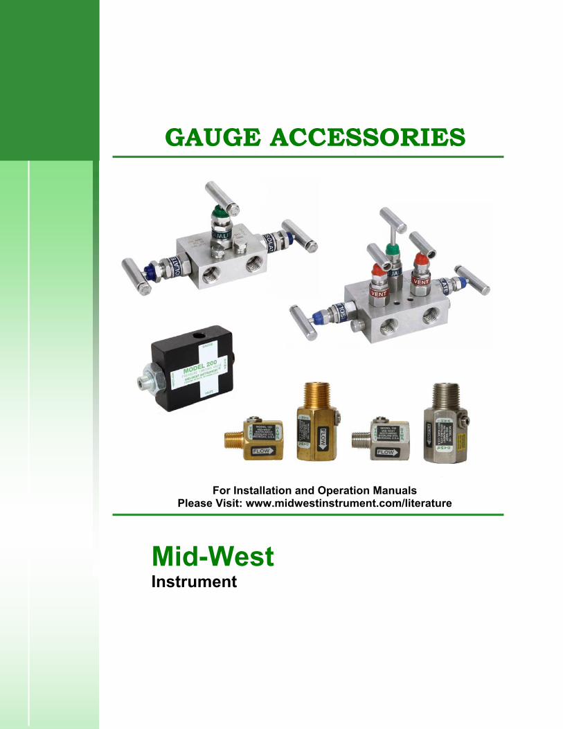
GAUGE ACCESSORIES
For Installation and Operation Manuals Please Visit: www.midwestinstrument.com/literature
Mid-West Instrument

Product Notes:Mid-West Instrument ®

3 & 5 Valve Mid-West Instrument
Bulletin No. MFLD/11 ®
Differential Pressure Manifolds
#113343 3-Valve Mini- Manifold
#107470 3-Valve Manifold
#107469 5-Valve Manifold
3 & 5 valve manifolds are designed for applications where direct mounting to an instrument is impractical or undesirable. The manifold is mounted to the lines from the instrument and signal rather than directly to instrument. Bubble tight shut-off, lightweight, super strong construction, compact designs that require less parts, chrome plated stems that prevent galling and stripping- these valves are built to perform under pressure. That’s why in some of the most rigid tests, manifolds provided by Mid-West Instrument consistently meet or exceed industry standards.
• Pressure rating: 6000 PSIG (414 bar) @ 240°F (115°C) • Instrument Connections: Std. 3 & 5 Valve = ½” FNPT / 3-Valve Mini-Manifold:= ¼” FNPT • Process Connections: Std. 3 & 5 Valve = ½” FNPT / 3-Valve Mini-Manifold:= ¼” FNPT • Dust cap: Protects spindle threads from dirt & dust. • Gland Nut & Lock Nut: Adjusts the packing compression to provide leak free operation
even on vacuum service. • Gland Packing: PTFE packing and metal seal ring ensures leak free operation. • Bonnet: Precisely machined bonnet adds a high level of reliability at maximum pressure
& temperature while increasing valve life and protecting stem threads from atmospheric corrosion. • Isolated Stem threads: Adjustable packing below stem ensures leak proof long service life • Less Parts: Less leak points and less fugitive emissions. • Test Ports: ¼” FNPT ports which may be used as test connections (#107470 & #107469) (#113343 Mini-manifold does not have test ports)
Teflon Packing, Integral (Body Material) Seat, and Stainless Steel Body
Model Number Description 113343 3-Valve 316 S.S. Single Block Mini-Manifold (1/4” FNPT Connections)
107470 3-Valve 316 S.S. Single Block Manifold (1/2” FNPT Connections) 107469 5-Valve 316 S.S. Single Block Manifold (1/2” FNPT Connections)
"Mid-West Instrument can supply many other manifolds that meet your specifications"

Manifold Dimensional Information
#113343 3-Valve Mini- Manifold
#107470 3-Valve Manifold
#107469 5-Valve Manifold
6500 Dobry Dr. • Sterling Heights, MI USA • Tel: 800-648-5778 Tel: 586-254-6500 Fax: 586-254-6509 Web Site: www.midwestinstrument.com • Email: [email protected]

Typical Manifold Installations
Mid-West Instrument offers multi valve isolation manifolds that protect our differential pressure gauges, switches and transmitters. This allows the user to install a complete assembly saving installation time and transactional cost. Assembles can be custom designed to fit each specific application.
Examples of Typical Manifold Installations
6500 Dobry Dr. • Sterling Heights, MI USA • Tel: 800-648-5778 Tel: 586-254-6500 Fax: 586-254-6509 Web Site: www.midwestinstrument.com • Email: [email protected]

Product Notes:Mid-West Instrument ®

Mid-West Instrument BULLETIN NO. 150/11
(Supersedes Bulletin NO. 150/01)
®
Model 150 “VARI-DAMP”
PULSATION DAMPENER • • differential pressure and compound The Model 150 “Vari-Damp” all purpose pulsation dampener features both a fine thread adjustable needle
valve for dampening characteristics and a precision ball check to block line surges, shock waves or fluid hammer. The Model 150 provides outstanding protection for applications where low displacement devices such as bourdon tube gauges or electronic transmitters are used or in high displacement devices where diaphragm, piston or bellows operated gauges, recorders or controllers are required. Double-ported instruments should be installed with a Model 150 on each input pressure line.
Provides infinitely adjustable dampening
Protects against surges and pressure shocks
• Use with all types of instruments and pressure gauges including
The Model 150 needle valve provides adjustable dampening characteristics by simply loosening the lock-nut on the adjusting screw and making a slight re-adjustment to the needle valve setting. Use of the Model 150 Is preferred over other commercially available designs that feature several piston diameters or porous metal discs requiring removal and/or disassembly to re-adjust. The Model 150 adjustable needle valve can be used as a complete shutoff to facilitate changing out of a gauge or instrument. This method is not intended to replace instrument block valves as continual over-torquing could damage the valve seat.
The Model 150 ball check offers protection surge and/or pressure spikes as indicated in the black lines in the graphs. The 316 stainless steel ball is driven on seat by the pressure surge and held on seat as long as the differential pressure exists across the ball, while metering pressure to the instrument through a calibrated, groove across the ball seating area.
The Model 150 is available in Brass or 316 Stainless Steel with ¼” or ½” NPT x FNPT connections
Made in the USA
Model Description Thread
Size Body
Material
L1 OAL Length (INCH)
L2 Thread Length (INCH)
MAX. W.P. PSIG (bar) Weight OZ
150-BO Male X Female NPT 1/4" NPT Brass 1.73 .56 3,000 (204) 6 150-BH Male X Female NPT 1/2" NPT Brass 2.31 .75 5,000 (340) 8 150-SO Male X Female NPT 1/4" NPT 316 S.S. 1.73 .56 5,000 (340) 6 150-SH Male X Female NPT 1/2" NPT 316 S.S. 2.31 .75 10,000 (680) 8
6500 Dobry Dr. • Sterling Heights, MI 48314 USA • Tel: 800-648-5778 Tel: 586-254-6500 Fax 586-254-6509 Web Site: www.midwestinstrument.com • Email: [email protected]

Standard Model Specification: 150-BO-00
3000 PSIG Working Pressure, Brass Body Material ¼” FNPT X ¼” MNPT Connections, Buna-N & Teflon Seals
Mid-West Instrument 1-800-648-5778
Basic Model
1 5 0
4 5 2 3 1
2 Material (Body) B Brass S 316 Stainless Steel Z Special (Un-coded Options)
3 Size O 1/4" FNPT X 1/4" MNPT H 1/2" FNPT X 1/2" MNPT Z Special (Un-coded Options)
4 Seal Materials / Temperature Range (Deg. F) 0 Buna-N & Teflon -30° to +250° 1 Viton & Teflon -15° to +400° 2 Neoprene & Teflon -45° to +300° 5 Ethylene & Teflon -70° to +250° 9 Special (Un-coded Options)
5 Options 0 NONE 9 Special (Un-coded Options)
INSTALLATION: Model 150 pulsation dampener can be installed directly on the instrument to be protected. The Model 150 features a built-in shutoff to allow instrument protection or removal. A shutoff valve in the line is not required. Avoid excessive force when closing to prevent seat galling.
NOTE: CAUTION TO BE EXERCISED WHEN ADJUSTING NEEDLE VALVE. DO NOT ADJUST MORE THAN TWO TURNS FROM CLOSED POSITION, LEAKAGE CAN ACCUR.
MAINTENANCE: The Model 150 can be cleaned by removing the needle adjusting screw, “O” Ring and Teflon backup ring. Metal parts should be cleaned in a commercial solvent.
6500 Dobry Dr. • Sterling Heights, MI 48314 USA • Tel: 800-648-5778 Tel: 586-254-6500 Fax 586-254-6509 Web Site: www.midwestinstrument.com • Email: [email protected]

BULLETIN NO. 200/11 (Supersedes Bulletin NO. 200/98)
Mid-West Instrument Model 200 “GAUGE MINDER”
PRESSURE LIMITING VALVE
®
• Pressure limiting valve prevents instrument over-range
• Adjustable needle valve dampens pulsation • Use with all types of instruments and pressure gauges
• Can be mounted in any position • Available in Aluminum, Brass, and 316 S.S.
Model 200 “Gauge Minder” features a pressure limiting valve that blocks off excess pressure to the instrument, preventing calibration failure, internal damage, and “blow-out” from over-ranging - a principal cause of instrument failure. Model 200 is supplied with a set of range springs designed to set the shutoff pressure point at any pressure from 50 to 5000 PSI. The automatic shutoff valve is positive on closing and is non-chattering. Once closed, pressure need only be reduced approximately 10% of set pressure to re-open the valve. The accuracy of the instrument used with the Model 200 is in no way affected up to the set point of the pressure shutoff.
Model 200 also features an adjustable needle valve designed to dampen system pulsation reducing instrument oscillation, improving readability, and extending instrument life without the addition of a snubber. Instrument reliability is improved and the cost to repair, re-calibrate, or replace the instrument is lowered. Operating safety is also enhanced.
Model 200 is available in Aluminum, Brass, or 316 Stainless Steel with 1/4” FNPT connections for 5000 PSI working pressure and in Brass or 316 Stainless Steel with 1/2” FNPT connections for 10,000 PSI working pressure. Buna N O-rings and Teflon backup rings are standard. Optional seal materials include Viton, Neoprene, and Ethylene Propylene.
The range springs are identified by color, as follows: Color of Shut-off Spring Range, PSI Silver 50 to 120 PSI Black 100 to 1100 PSI Gold 1000 to 5000 PSI
Brass Model 200
Aluminum Model 200
Model Process Connections Thread
Size Body Material Valve Shut-Off
Pressure Range MAX. W.P. PSIG (bar)
Approx. Weight
200-AO Female x Female NPT 1/4" FNPT Aluminum 50 to 5000 PSIG 5,000 (340) .80 oz
200-BO Female x Female NPT 1/4" FNPT Brass 50 to 5000 PSIG 5,000 (340) 2.2 Lbs
200-BH Female x Female NPT 1/2" FNPT Brass 50 to 5000 PSIG 10,000 (680) 2.2 Lbs
200-SO Female x Female NPT 1/4" FNPT 316 S.S. 50 to 5000 PSIG 5,000 (340) 1.25 Lbs
200-SH Female x Female NPT 1/2" FNPT 316 S.S. 50 to 5000 PSIG 10,000 (680) 1.25 Lbs
6500 Dobry Dr. • Sterling Heights, MI 48314 USA • Tel: 800-648-5778 Tel: 586-254-6500 Fax 586-254-6509 Web Site: www.midwestinstrument.com • Email: [email protected]

Model 200 “GAUGE MINDER” PRESSURE LIMITING VALVE
INSTALLATION AND MAINTENANCE INSTRUCTIONS:
Model 200 “Gauge Minder” is mounted in-line with the instrument to be protected and may be mounted in any position. The automatic shutoff set point is adjusted by loosening the lock nut marked “adjust” and turning the adjustment screw. Turning “clock-wise” increases the shutoff pressure and turning “counter clock-wise” reduces the shutoff pressure. The Model 200 is shipped with a 50 to 120 PSI range spring installed, unless otherwise requested. Two additional springs for higher ranges are included as separate parts. The range spring can be changed by removing the adjustment screw.
The range springs are identified by color, as follows: Spring Range, PSI Color of Shut-off Silver 50 to 120 PSI Black 100 to 1100 PSI Gold 1000 to 5000 PSI
The operating limits of the instrument to be protected must be considered when determining the point to set the Model 200 shutoff pressure. Commonly, a setting of 110% of full scale of the instrument is used. Instruments with full scale ranges above 1000 PSI generally have a lower safety factor. It is necessary in this instance to set the shutoff point to 100% of full scale of the instrument to prevent calibration failure. After adjustment of the shut-off pressure of the Model 200 is completed the instrument should be over-pressured for several minutes to verify operation. If indicated instrument pressure falls with the shut-off valve closed, there is a connection leak from the Model 200 to the instrument which must be corrected. If indicated instrument pressure rises beyond the shut-off point, the Model 200 is defective and should be returned if new or repaired by cleaning or installing new seals if previously used.
CAUTION: Do not adjust the set point with system pressurized and in the shutoff mode. Reduce system pressure until shutoff valve is open, then make set point adjustment.
Model 200 can be shut off manually with the needle valve marked “damp”. The lock nut must be loosened. The valve screw is turned “clock-wise” to close. Turning the valve screw “counter clock-wise” one turn from closed position gives a range of pulsation dampening. Adjust the amount of dampening necessary to stop pointer oscillation on the instrument.
NOTE: Caution must be exercised when adjusting needle valve. Do not adjust more than two turns from closed position. Leakage can occur.
Made in the USA
6500 Dobry Dr. • Sterling Heights, MI 48314 USA • Tel: 800-648-5778 Tel: 586-254-6500 Fax 586-254-6509 Web Site: www.midwestinstrument.com • Email: [email protected]

Standard Model Specification: 200-AO-00
5000 PSIG Working Pressure, Aluminum Body Material ¼” FNPT X ¼” MNPT Connections, Buna-N & Teflon Seals
Mid-West Instrument 1-800-648-5778
Basic Model
2 0 0
4 5 2 3 1
2 Material (Body) A Aluminum B Brass S 316 Stainless Steel Z Special (Un-coded Options)
3 Size O 1/4" FNPT X 1/4" MNPT H 1/2" FNPT X 1/2" MNPT (Not available on Aluminum Body Material) Z Special (Un-coded Options)
4 Seal Materials / Temperature Range (Deg. F) 0 Buna-N & Teflon -30° to +250° 1 Viton & Teflon -15° to +400° 2 Neoprene & Teflon -45° to +300° 5 Ethylene & Teflon -70° to +250° 9 Special (Un-coded Options)
5 Options 0 NONE 7 Factory Preset Shutoff Point (Above 1500 PSIG) 8 Factory Preset Shutoff Point (Up to 1500 PSIG) 9 Special (Un-coded Options)
Made in the USA
6500 Dobry Dr. • Sterling Heights, MI 48314 USA • Tel: 800-648-5778 Tel: 586-254-6500 Fax 586-254-6509 Web Site: www.midwestinstrument.com • Email: [email protected]

Product Notes:Mid-West Instrument ®

Mid-West Instrument DDiiaapphhrraaggmm // CChheemmiiccaall SSeeaallss
HOW IT WORKS: A diaphragm seal, when properly mounted to its sensor and filled will accurately transmit process pressure to the instrument. Pressure exerted on the flexible diaphragm is transmitted hydraulically to the instrument through the fill fluid, which fills the void between the diaphragm and the instrument, (including the bourdon tube, in the case of a pressure gauge.) APPLICATION CONSIDERATIONS: The following should be considered when choosing a diaphragm seal: 1. Process Characteristics: Pressure, temperature, (see tables, this page) chemical compatibility and viscosity. 2. Seal Mounting: Connection to process (threaded, flanged, clamped, in-line) Connection to instrument (usually NPT). 3. Ambient Characteristics: Temperature, corrosive atmosphere, etc.
4. Instrument Considerations: Sufficient fluid displacement is required to drive instrument through its full range (this means, for example, you can’t put a large gauge on a small seal); remote instrument placement requires a capillary connecting instrument to seal. 5. Vacuum Considerations: High vacuums (over 25” Hg vac.) or vacuums with high temperatures require special fill selection, preparation, and procedures, as well as careful diaphragm selection. NOTE: Improper selection may result in system failure and possible damage or injury. Mid-West can provide application assistance, but final compatibility is the responsibility of the buyer. Proper selection of seal can reduce or eliminate any additional system error caused by adding a Diaphragm Seal to your instrument. SEAL TYPES: Standard Seals (pages 2&3) include Threaded off-line, threaded in-line, and flanged off-line types in many materials for a variety of applications:
®
1
SPECIAL DESIGNS: Mid-West is ready to work with you on any high-performance diaphragm seal application, (that might exceed the stated limit below) such as high vacuum, high temperature, high sterility, custom design or high static pressure with a low differential span, or high vacuum with high temperature.
PSI Lower Housing
Maximum 1,500 Metal, w/S.S. Bolting (at 100°F)
working 2,500 Metal,w/Std. Bolting (at 100°F)
pressure 5,000 Metal, w/Hi-Press. Bolting (at 100°F)
Per flange rating ASA Flange (Per Flange Spec)
300 Non-Metalic (at 140°F)
Diaphragm Size 5 Seal Size 6 Seal Min. Metal 25 PSI 10 PSI
working Teflon 20 PSI 8" WC
pressure Viton 5" WC N/A
Vacuum Metal -21" hg -24" hg
Limits Teflon -23" hg -26" hg
Viton -29" hg N/A
Maximum Diaphragm Lower Temperature Material Housing
650°F Welded Metal Metal 450°F Teflon Metal 300°F Viton Metal 140°F n/a Nonmetal
MATERIALS: Lower housings: 316 S.S. is standard with a large selection to suit a wide variety of applications (see table 1, page 3) Diaphragms: Standard metal diaphragms are convoluted and made of 316 S.S. Many other materials are available for corrosion resistance or extra sensitivity. (see table 6, page 3) Gaskets: Standard gaskets are Teflon on the process side of diaphragm (Grafoil for hi temp.), and Viton on the fill side. Other materials are available.
Diaphragm Seals (or Chemical Seals) use a flexible barrier, or diaphragm, to isolate a pressure sensor (gauge, switch, transmitter, or transducer) from adverse effects of the process fluid.
1


Mid-West Instrument D
®
Diiaapphhrraaggmm SSeeaall WWoorrkksshheeeett
Customer Information:
• Company Name:________________________________________________ • Address_______________________________________________________ • Contact:_______________________________________________________ • Phone number: _________________________________________________ • Email address: __________________________________________________ • Date: _________________________________________________________ Process Information:
• Process Temperature Range: _______________________________________ • Ambient Temperature Range: ______________________________________ • Process Fluid/Media: ______________________________________________ • Current Pipe/Tank Material: ________________________________________ • Maximum Pressure on Seal: ________________________________________ • Differential Pressure Range: _______________________________________ • Working Pressure on Seal: _________________________________________ • Other (vibration, pulsation, etc.): ___________________________________ Seal Information:
• Mounting - Direct or Remote: ______________________________________ • (if remote) Capillary Length: _______________________________________ • Process Connection: ______________________________________________ • Required date for completed seal assembly?___________________________ Midwest Differential Gauge Information:
Model number used in application:_____________________________________ Quantity of differential gauges used in application:________________________ Additional Notes:
______________________________________________________________________________________________________________________________________________________________________________________________________________________________________________________________________________________________________________________________________________________________________________________________________
6500 Dobry Dr. • Sterling Heights, MI 48314 USA • Tel: 800-648-5778 Fax: 586-254-6509 Web Site: www.midwestinstrument.com • Email: [email protected]