2012EU ACC Viewer
42
www.lgeaircon.com 2012 LG AIR CONDITIONERS ACCESSORIES Distributed by LG Elecrcs AE Ca, Cercal Ar Cdg 20 Yeouido-dong, Yeongdeungpo-gu, Yeouido P.O.Box 335 Seoul, 150-721, Korea. Phone : +82-2-3777-7934 Fax : +82-2-3777-3099 www.lg.c www.lgearc.c Copyright © 2012 LG Electronics. All rights reserved.
Transcript of 2012EU ACC Viewer

7/27/2019 2012EU ACC Viewer
http://slidepdf.com/reader/full/2012eu-acc-viewer 1/44
www.lgeaircon.com
2012LG AIR CONDITIONERS ACCESSORIES
Distributed by
LG ElecrcsAE Ca, Cercal Ar Cdg20 Yeouido-dong, Yeongdeungpo-gu, Yeouido P.O.Box 335 Seoul, 150-721, Korea.
Phone : +82-2-3777-7934 Fax : +82-2-3777-3099
www.lg.c www.lgearc.c
Copyright © 2012 LG Electronics. All rights reserved.

7/27/2019 2012EU ACC Viewer
http://slidepdf.com/reader/full/2012eu-acc-viewer 2/44
GHGReduction
GREENOVATIONReducing greenhouse gas emissions, enhancing green growth with suppliers, developing new green businesses.
HVAC
HVAC
Summer (Cooling)
Cooled air
Surface 30 C
Underground 15+/-5 C
Cool the air thanks to Multi V Water
and a “heat exchanger” in the ground
Heat transfer
from the ground
Heated air
Surface -10 C
Underground 15+/-5 C
Winter (Heating)Heat the air thanks to Multi V Water
and a “heat exchanger” in the ground
Multi V Water
Heat Exchanger
Heat transfer
to the ground
We’re n the bsness of creatng comfort for any season of the year throgh Heatng, Ventlaton and Ar-Condtonng soltons.
LGE provdes a total HVAC system wth optmzed heatng, ventlaton and ar-condtonng soltons careflly adapted to the nqe
condtons of each ste drng the bldng’s constrcton or renovaton. The company s also engagng n the development of green
bldngs throgh ts lne of prodcts sng renewable e nergy. For example, or MuLTi V Water ses geothermal energy, whch s
known as a constant sorce of heatng and coolng that mantans a temperatre of 15±5C regardless of the srface temperatre.
LG Electroncs’ vson s to grow nto
a leadng envronmentally conscos
company by workng to protect the global
envronment and creatng prodcts wth
envronmentally frendly featres.
Green Vson
Green Goals
Or green management actvtes nclde
greenhose gas redcton across the
entre prodcton process, enhancng
green and shared growth wth spplers,
and developng green bsnesses to
secre new growth opportntes.
Green Management
Eco Strategy Team
Green ProductExpert Committee
Green MarketingCouncil
Eco-Design Committee
Chairman : CTO
Members : Head of Research Center (Executives)
*
7
3
* :
LG Electroncs has establshed a low-
carbon green management system toprovde low carbon vale to cstomers
throgh volntary greenhose gas (GHG)
redcton. Throghot ts actvtes, LGE
s creatng vale for cstomers and
stakeholders, and protectng the natral
envronment.
Major decsons n green management
at LGE are made by the Eco-Desgn
Commttee; comprsed of the heads of
laboratores nder the CTO, and spported
by the Green Prodct Expert Commttee,
consstng of members workng on R&D
and management of green prodcts, and
the Green Marketng Concl, n whch
dvson marketng managers set-p green
marketng strateges.
Secre ftre green growth drvers n energy, water treatment and envronmental bsnesses
• Solar Business
• Lighting Solution Business
• HVAC Business
• Water Treatment Business
• Smart Grids Business
Green Strategy Green Businesses
• Productivity enhancement Low-Carbon Factories • Product competitiveness
Low-Carbon Products
• Operational efcienciesLow-Carbon Value Chain
• Social contributionLow-Carbon Culture

7/27/2019 2012EU ACC Viewer
http://slidepdf.com/reader/full/2012eu-acc-viewer 3/44
LGE’s heating and air conditioning products are continually being developed with energy savings, reduction
o hazardous substances, and impact on the environment in mind. In particular, we have made great strides
in the use o renewable energies through our cutting edge systems.
Energy-saving, High-efciency Inverter Compressor and MotionSensorThs sper energy-savng nverter compressor technology saves p
to 72% of electrcty by atomatcally controllng the nt accordng to
the ndoor temperatre and a moton sensor.
High-efciency Central Air Conditioning Systemusng eco desgn for every part of the prodct has mproved the
energy efciency of this air conditioning system. It features the
world’s rst heat exchanger, providing continuous heating, as well as
Korea’s rst high-efciency, high-pressure inverter compressor.
High-perormance, High-efciency Inverter Heat Pump
Air ConditionerThese compact otdoor nts featre enhanced heatng and
coolng technology, low-nose ndoor nt technology and a hghly
efcient inverter heat pump, with up to 115% improvement on cost
effectveness n comparson to constant-speed ar condtoners.
Geothermal Air Conditioner and Heaterusng resable geothermal energy to redce greenhose gas
emissions, this high-efciency DC Inverter technology allows
uninterrupted ow of the magnetic eld within the motor of the
compressor n the otdoor nt.
Hybrid solar air conditionerThis product incorporates the energy efciency enhancement of a
power saving inverter and allows for a 100% solar powered air purier
fncton as well as a 15% solar powered coolng fncton, a “Hman
Care Robot,” and Green-tea HEPA and Platinoid enzyme lters.
GREEN HEATING AND AIR CONDITIONING
• 2010 Green Technology Certication(inverter and solar technology) - Korea
• 2010 Energy Winner Award Grand Prix - Korea
• 2010 Green Growth Brand - Korea
• Carbon Footprint Label - Korea
Green Prodct Evalaton System
Green Technologes
Green R&D investment
LGE establshed an envronmental accontng gdelne n
2009 for green R&D nvestment. LGE nvested KRW 808
bllon for green R&D n 2010. The majorty of the nvestment
was used for improving product energy efciency and
improving resource efciency.
The Eco IndexThe Eco-index s LGE’s own ratng system for managng
environmental performance and goal setting, which quanties the
eco desgn level of prodcts n terms of ther eco-conscosness
(Green 1-Star, 2-Star and 3-Star). The Green index measres three
areas of prodct footprnts sch as Clmate mpact, Chemcals
sed and Materals sed. We wll contne ncreasng the nmber of
prodcts to reach the hgher Eco-index.
Evaluating the Carbon Footprint o the Product ProcessSnce 2002, LGE has been condctng Lfe Cycle Assessment
(LCA) to evalate the entre process’ carbon emsson and to flly
tlze LCA to develop low carbon prodcts. in 2011, LGE plans to
establsh an nfrastrctre that wll enable LGE to perform LCA on
entire product lines and to continuously and efciently evaluate
greenhose gas emsson from the entre prodct process.
LGE has been condctng R&D to redce the envronmental
impact of products, developing a range of highly efcient
prodcts, replacng hazardos sbstances n prodcts, mprovng
prodct desgn to facltate recyclng, and establshng an
nfrastrctre to enable the development of green prodcts and
technologes.
GREENER PRODUCTSLGE’s Green Product Strategy aims at minimizing the environmental load in every stage o the product
liecycle and improving energy, resources and humanity – through production o highly energy-efcient
products, reduction o raw material usage, and improvement o living environments or everyone.
Prze-Wnnng Technologes
Awards & Certifcations
Green Product Strategy
Phase ot the se of certan
hazardos materals
Decrease nose and vbratons
Redce CO2 emssons throghotprodct lfecycle
Redce stand-by powerconsmpton
use recyclable materals
Redce prodct weght/volme
HazardousSubstances
Management
Home
Environment
CO2 EmissionsReduction
Energy Efficiency
Enhancement
Recyclability
Improvement
ResourceReduction
R e s o u r c
e s H
u m a n
Green
Product
E ner g y
Energy Resources Humanity
Energy-Focusingontwo
keyareas:improving
energyefficiencyand
reducinggreenhouse
gasemissionsfromthe
manufacturing process.
Resources-committed
tostrategiesoflowering
resourceusagein
productsandimproving
productrecyclability.
Humanity-Providing
greenvalueto
customers

7/27/2019 2012EU ACC Viewer
http://slidepdf.com/reader/full/2012eu-acc-viewer 4/44
OUR AIR-CONDITIONERS MAKE THE MOST
OF THE ENERGY THEY ARE USING
Wth dfferent coolng and heatng needs throghot the year,
LGE’s prodcts are desgned for optmal performance accordng
to each season and geographcal area. The Seasonal Energy
Efciency Ratio and the Seasonal Coefcient of Performance
llstrate best how each prodct wll operate n heatng and/
or coolng mode dependng on where yo lve and on the bass
of real-life use conditions: Seasonal efciency integrates the
axlary modes of operaton of the prodct, where energy se s
stll necessary.
Calclatons are smlated nder dfferent combnatons of
ndoor and otdoor average temperatres over all seasons
correspondng to one ot the three Erope clmate zones. LG
prodcts mprove the ndoor envronment and save energy n a
cost efcient way.
LG Electroncs prodcts dsplay ther energy credentals on the standardzed energy label, a transparent and easy to compare tool. An
arrow ndcates whch energy class yor prodct belongs n on a scale from A to G. The hgher the class, the less energy-hngr y yor
prodct s at delverng heatng or coolng. The label wll also gve yo an estmate of the prodct’s annal energy consmpton n kW.
LG Electroncs s nvolved n a cross-ndstry evalaton whereby
the performance of the otdoor nts of VRF systems s
volntarly measred and rated. Commtted to prodcng energy
efcient products, LG Electronics has supported this initiative
snce ts start. The standard, coordnated by Erovent, wll allow
the energy efciency of the product to be displayed in heating
and coolng mode and allow sde-by-sde comparson wth
competng prodcts. in the end, the ser can make the most
nformed choce when prchasng an LG Electroncs prodct,
from both an envronmental and a prcng pont of vew.
LG Electroncs has mproved ts prodcts’ desgn so that they
consme less energy whle satsfyng all yor coolng and
heatng needs.
Less s More
Eropean reglatons on energy-related prodcts (ErP) reqre
manufacturers to produce energy efcient products that consume
less scarce raw materials and energy from production to nal use.
The 20/20/20 by 2020 polcy ams to ensre 20% less prmary
energy consmpton and 20% less greenhose gas emssons,
whle the share of renewable energes ncreases by 20% by 2020.
LG Electroncs ar condtoners ntegrate these expectatons and
contrbte ther far share n global clmate protecton.
The rle of 20
LG Electroncs deploys prodcts wth envronmentally-frendly
featres both n heatng and coolng modes that go beyondthe mnmm reqrements set by Eropean legslaton. Wth a
ratng of close to 4, LG Electroncs prodcts m ake the most of
the energy they are sng. No energy s wasted, whle we help
yo decrease yor energy blls - all year long.
Gong beyond - ErP
Seasonal Efciency Energy Label
VRF Certication
How to calculate seasonal efciency of splits?
LG Electroncs spples eqpment that s beng notced for tsdesgn and performance and not for ts nose. The sond power
of our units in dB are displayed in the energy label for both
ndoor and otdoor nts, n conformty wth lmt vales that are
set by Eropean Reglatons.
LG Electroncs s actally dong ts best for redcng nose levels
of ts eqpment. We brng to or cstomers prodcts that emt
30 % less nose than reqred by Eropean law.
The Sond of Slence
ir :
r : r r ( x i
EUEco design
LGElectronics
0 10 20 30 40 50 60 70 80
Comparson of nose levels
For sngle dcts below 12 kW the
same nformaton s dsplayed, wth
some adjstments: Sngle dcts
ndcate the horly energy consmpton
n kW whereas doble dcts ndcate
the yearly annal consmpton n kW.
Fnally, performances of sngle and
doble dcts n heatng and/or coolng
mode are stll sbject to nomnal
calclatons, not seasonal.
For splt ar condtoners below 12 kW
that provde both heatng and coolng,
the energy label wll ndcate two energy
classes-one for heatng and one for
coolng. Also dsplayed are capacty n
kW, annal energy consmpton and
the seasonal performance rato for
heatng and coolng.
Crrent energy label wll reman
ntl 2012.
T
x
h ir n : T
r : f rch n r x cu iv
r l r i
r r
l r
i i
x i l i r
l r
r i
lll
r lin r i n
l ul
r h in 3r i n
l ul
r n
i n n i i n
u li
r r rm n
v r n ir n
Th rm n
n m
m
r n h r
In r
r i n
r i l l
i n
i n
l r ni
l r ni
i u
u
r
v l i
≧ .
. ≦ .
. ≦ .
.≦ .
. ≦ .
.≦ .
. ≦ .
. ≦ .
. ≦ .
.
n ri n
l
IT l
≧ .
. ≦ .
. ≦ .
. ≦ .
.≦ .
. ≦ .
. ≦ .
. ≦ .
. ≦ .
≦ .
≧ .
. ≦ .
. ≦ .
. ≦ .
. ≦ .
. ≦ .
. ≦ .
. ≦ .
. ≦ .
.
n ri n
l
I T l
≧ .
.≦ .
. ≦ .
. ≦ .
. ≦ .
. ≦ .
. ≦ .
. ≦ .
. ≦ .
.
.
. ≧ .
. ≧ .
. ≧ .
. ≧ .
. ≧ .
. ≧
.
. ≧ .
. ≧ .
. ≧ .
. ≧ .
. ≧ .
. ≧
EER>3.20
3.20≧EER>3.00
3.00≧EER>2.80
2.80≧EER>2.60
2.60≧EER>2.40
2.40≧EER>2.20
2.20≧EER
A
B
C
D
E
F
G
COP>3.60
3.60≧COP>3.40
3.40≧COP>3.20
3.20≧COP>2.80
2.80≧COP>2.60
2.60≧COP>2.40
2.40≧COP
r r
i :
: i
Several rating
temperature
Includes energy
consumption in
auxiliary modes
No longer
operations
at full load
For cooling 1 region
to calculate SEER
For heating 3 regions
to calculate SCOP*
Reference
design conditions
supplied by Reg
To reflect performance
over entire season
Thermostant off
Stand by mode
Off mode
Crankcase heater
Integrates
operations at
partial load
7
3
x i
r
l i
3 7
*SCOP: availablefrom2013
7/27/2019 2012EU ACC Viewer
http://slidepdf.com/reader/full/2012eu-acc-viewer 5/44
Remote Controller
Central Controller
Electronc Accessory
13
18
35
Contents
12
52
68
V -net
Mechancal Accessory
Ppng Accessory

7/27/2019 2012EU ACC Viewer
http://slidepdf.com/reader/full/2012eu-acc-viewer 6/44
V - n e t
M e c h a n
i c a l A c c e s s o r y
P i p i n g A c c e s s o r y
Ree Crller Ceral Crller Ceral CrllerElecrc
Accessr
Wired Remote ControllerWirelessRemote
Controller
SimpleController
AC Smart ll,Option Kit
&128 Units
Expansion Kit
ACP&
AC Manager
BuildingNetwork Unit
AHUApplication Kit
PI 485&
DO Kit
Standard Delxe Smple
LG Commercal Ar Condtoners2012 Lne-p
PQNFB17B0(BACnet/Modbus)
PQNFB16A1(LONWORKS®)
PQCPA11A0E(Wthot iO)
PQCPB11A0E(Wth iO)
PQCSS520A0E(ACManager)
PQWRHDF0
PDi,
Dry Contact,
Varable Water Flow Control Kt,
independent Power Modle,
CO2 Sensor,
Remote Temperatre Sensor,
Cool/Heat Selector,
Grop Control Wre,
Zone Controller,
Low Ambent Kt,
CTi
(Communcaton Transfer interface)PQRCVSL0
PQRCVSL0QW
PQRCuDS0(Whte)
PQRCUDSOB(Blue)
PQRCuDSOS(Slver)
PRCKD20EPRCKD40E
Control kt
PuCKA0PRCKA0
Comm. kt
PATX13A0EPATX20A0EPATX25A0E
PATX35A0EPATX50A0E
Expanson kt
PRLK048A0EEV kt
AC Smart ll
PMNFP14A1PMNFP14A0PHNFP14A0PSNFP14A0
Pi 485
PQNFP00T0DO KtOpton Kt
PQCSE341A0PQCSE342A0
PQCSW320A1E
Expanson Kt
PQCSE440u0
PQRCVCL0Q(Black/Simple)
PQRCVCL0QW(Whte/Smple)
PQRCHCA0Q(Black/Simple for Hotel)
PQRCHCA0QW(Whte/Smple for Hotel)
AC EZ
PQCSZ250S0
7/27/2019 2012EU ACC Viewer
http://slidepdf.com/reader/full/2012eu-acc-viewer 7/44
12 /13LG Air Conditioners 2012
V - n e t
M e c h a n i c a l A c c e s s o r y
P i p i n g A c c e s s o r y
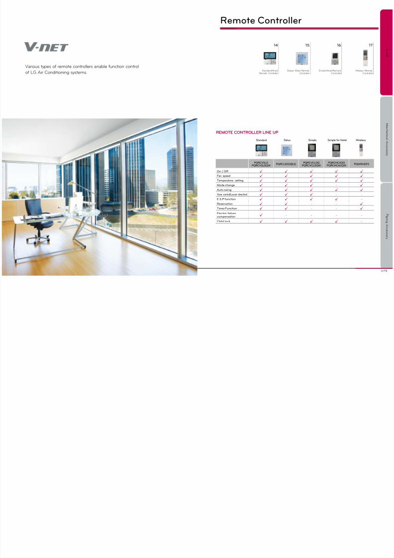
Remote Controller
PQRCVSL0PQRCVSL0QW
PQRCUDS0(B,S)PQRCVCL0Q
PQRCVCL0QWPQRCHCA0Q
PQRCHCA0QWPQWRHDF0
On / O Fan speed Temperature setting Mode change - Auto swing Vane control(Louver direction) - -
E.S.P unction -
Reservation - - Timer Function - - Electric ailurecompensation - - - -
Child lock -
Varos types of remote controllers enable fncton control
of LG Ar Condtonng systems.
Standard Simple for HotelDelux Simple Wireless
REmotE ContRoLLER LinE up
14 15 16 17
Standard WredRemote Controller
Delxe Wred RemoteController
Smple Wred RemoteController
Wreless RemoteController

7/27/2019 2012EU ACC Viewer
http://slidepdf.com/reader/full/2012eu-acc-viewer 8/4414 /15LG Air Conditioners 2012
V - n e t
M e c h a n i c a l A c c e s s o r y
P i p i n g A c c e s s o r y
Standard Wired Remote ControllerProvdng easy control of one or a grop of ndoor nts to varos applcatons. Toch screen wth a premm desgn for excellence n appealng nterors.
Deluxe Wired Remote Controller
PQRCUDS0 /
PQRCUDS0B / PQRCUDS0SPQRCVSL0 / PQRCVSL0QW
PQRCVSL0 / PQRCVSL0QW
Operating mode On/Off / Fan speed / Mode / Temp.
Max. no. o indoor units 16 indoor units
On / O LED
Room temp.
Fan / Plasma / Swirl / Heater
Vane control(Louver direction) / Auto swing / Fan auto
E.S.P unction
Reservation On/Off / Weekly / Smple / Sleep / Holday
Timer unction
Child lock
Electric ailure compensation Max 3 hors
Wireless remocon receiver
Main/Sub setting o indoor units(For override unction)
★
2 Controllers to 1 indoor unit ★
Group and central control at the same time ★
Ventilation mode setting ☆
Rapid ventilation ☆
Power saving ventilation ☆
Size(mm) 120 x 120 x 15
Backlight Unit ★
PQRCUDS0 / PQRCUDS0B / PQRCUDS0S
Operating mode On/Off / Fan speed / Mode / Temp.
Touch screen / LCD back_light
Room temp
Fan / Plasma / Swirl / Heater
Vane control(Louver direction) / Auto swing
E.S.P unction
Reservation Weekly / Smple
Timer unction
Child lock
★ Applcable for MuLTi V ii and iii seres.☆ Applcable for ECO V ii seres. ※ Terminal Block included. (Applied to models produced since ’10 Nov.)※ Compatble wth SCAC models connected to wred remote controllers.※ Refer to each model PDB for applicable models.
PQRCVSL0QW
(Whte)
PQRCVSL0
(Black)
PQRCuDS0
(Whte)
PQRCUDS0B
(Blue)
PQRCuDS0S
(Slver)
※Refer to each model PDB for applicable models.
For Air conditioner FEATURES FEATURES

7/27/2019 2012EU ACC Viewer
http://slidepdf.com/reader/full/2012eu-acc-viewer 9/4416 /17LG Air Conditioners 2012
PQWRHDF0
Operating mode On/Off / Fan speed / Mode / Temp
Room temperature checking
Chaos swing / Jet cool
On/O timer
Sleep mode auto
Main / Sub setting o indoor units(For override unction)
★
PQRCVCL0Q / PQRCVCLOQW PQRCHCA0Q / PQRCHCA0QW
Operation mode On/Off / Fan speed / Mode / Temp. On/Off / Fan speed / Temp.
Room temp
Child lock
Mode change Coo lng / Heat ng / F an / Dehm d fy / Ato Onl y c hangeable by c en tral cont rol le r
Back Light
V - n e t
M e c h a n i c a l A c c e s s o r y
P i p i n g A c c e s s o r y
Simple Wired Remote Controller Wireless Remote Controller
PQWRHDF0
PQRCVCL0Q(Black) / PQRCVCL0QW(White)
PQRCHCA0Q(Black) / PQRCHCA0QW(White)
★Applcable for MuLTi V ii and iii seres.※Refer to each model PDB for applicable models.
※Combnaton wth other remote controllers for varos ndoor nts.
※Compatble wth SCAC models connected to wred remote controllers.※Refer to each model PDB for applicable models.
PQRCVCL0Q
(Black/Simple)
PQRCHCA0Q
(Black/Simple For Hotel)
PQRCVCL0QW
(Whte/Smple)
PQRCHCA0QW
(Whte/Smple For Hotel)
FEATURES FEATURES
MODEL NAME & APPLICABLE MODELSCOMBINATION
Type CST, SRAC, CVT, Duct, Floor Standing
PQWRHDF0 H/P
A smple way to control offce or hotel applcatons n a compact desgn. Wreless control to operate ar condtoners more convenently.
7/27/2019 2012EU ACC Viewer
http://slidepdf.com/reader/full/2012eu-acc-viewer 10/4418 /19LG Air Conditioners 2012
V - n e t
M e c h a n i c a l A c c e s s o r y
P i p i n g A c c e s s o r y
Central Controller
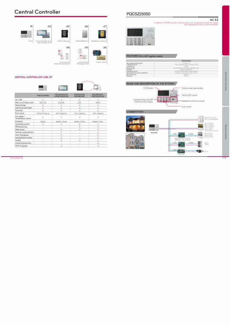
CEntRAL ContRoLLER LinE up
19 20 22 26 27
AC EZ AC Smart l l, Opt on K t &128 unt Expanson Kt
ACP & AC Manager BNU(LONWORKS®) BNU(BACnet / Modbus)
28 30 32
AHu Comm. kt,AHu Comm. kt & EEV kt
AHu Control kt,AHu Expanson kt
Pi 485 / DO Kt
PQCSZ250S0PQCSW320A1E
(+PQCSE440U0)PQCPA11A0EPQCPB11A0E
PQCPB11A0E+PQCSS520A0E
On / O
Max. no. o indoor units 32(16/16) 64(128) 256 4,096
Mode change
Control o each room
Total lock
Error check LED/LCD dsplay Self- dagnoss Self- dagnoss Self- dagnoss
Fan speed /Temperature control
Schedule Weeky Weekly / Yearly Weekly / Yearly Weekly / Yearly
Ventilation control
PDI Monitoring - -
Web access -
Set temp. range restriction - -
Auto Changeover - -
Temperature limit control - -
History -
Interlocking unction - - -
Multi languages - -
PQCSZ50S0
Max. Indoor unit to control 32 indoor unts
Individual Control On/Off / Operaton Mode / Fan Speed / Temp
Lock unction Central
Mode change Coolng / Heatng / Fan / Dehmdfcaton / Ato
Schedule 8 event schedle/day
Ventilation control On/Off / Ventlaton Mode / Rapd Ventlaton
Display(All Indoor status indication) Operaton, Set temp, Room Temp, Schedle
Dimension(mm) 190x120x17
Power(V) DC 12V
AC EZ
PQCSZ250S0
(For LGAP applied models)
AC 220V
AC 220V MuLTi,Sngle A
MuLTi V PLuS ii
MuLTi V SYNC ii
MuLTi V SPACE ii
MuLTi V Water ii
MuLTi V MiNi
MuLTi V PLuS
MuLTi V SYNC
MuLTi V SPACE
PMNFP14A0
PMNFP14A0 (Max 16Indoors)
PMNFP14A1 (Max 64Indoors)
MuLTi V iii Heat Pmp
MuLTi V iii Heat Recovery
PI 485
PI 485
pQCSZ250S0
FEATURES (For LGAP applied models)
NAME AND DESCRIPTION OF THE SYSTEM
LCD Dsplay
indvdal indoor On/Offcontrol and LED Dsplay
Control mode select btton
Total On/Off control
Detaled Fncton control part
Lock control
COMBINATION
in addton to On/Off control, more fnctons sch as operaton mode, fan speed,and schedlng can be rn and montored.
(ARuN40GS2A needs Pi 485)
PHNFP14A0
ECO VPI 485

7/27/2019 2012EU ACC Viewer
http://slidepdf.com/reader/full/2012eu-acc-viewer 11/4420 /21LG Air Conditioners 2012
V - n e t
M e c h a n i c a l A c c e s s o r y
P i p i n g A c c e s s o r y
Option Kit & 128 Units Expansion Kit
AC Smart II : PQCSW320A1E 128 Units Expansion Kit : PQCSE440U0Option Kit : PQCSE341A0 / PQCSE342A0
Schedle Wzard Fc
Schedle pattern wzard s the process of confgrng the operaton of the nt n weekly or daly pattern. The patterncreated throgh the schedle pattern wzard can be appled to the grop as a schedle throgh schedle wzard to bedescrbed n the next secton.
new Gui
it s more easy to se and control the prodcts.
AC Sar ii o K del ae : pQCSE341A0 / pQCSE342A0
• DescriptionAC Smart ii addtonally provdes varos convenent opton fnctons for the sers to se. Theseaddtonal fnctons are provded n SD card format. When the ser nserts the SD card to theman nt of the AC Smart ii, the opton fncton can be actvated and sed.
• Option Function- Web schedle + Power consmpton statstcs fncton (PQCSE342A0)- Web schedle fncton (PQCSE341A0)
• Web based schedule setting functionBy using the web server function of AC SMART II, you can set and apply the schedule ofAC SMART ii even from remote locatons. The admnstrator can manage the schedle ofAC SMART ii throgh the network free from locaton and redce any nnecessary operatons ofthe nt by sng the schedle fnctons.
• Power consumption statistics functionYo can vew the power consmpton nformaton of the ar condtoner. The power consmptons provded n varos methods ncldng total sage, sage by perod, monthly/daly sage etc.By using the statistics information, the administrator can effectively analyze and manage theenergy sage. To se the power consmpton statstcs fncton, the PDi and watt-meter tomeasre the power consmpton mst be connected to AC SMART ii.
1 . Se lect sched le pa tt er n t yp e 2. Ad d/ Ed t sch ed l e pa tte rn 3 . Ent er sched le pa tt er n n am e 4. Ed t s ch ed l e p at te rn
Web Access
Screen Saver
Easy Software
Upgrade by USB
Emergency
USB Option Kit
- Remote Management
- Error Report via E-mail
Operation Report- Operating Time,
Percentage, History 128 Indoor unitsExpansion Kit
PQCSE440U0
PQNFP00T0
DI RS485
• 7”Touch Screen / GUI
• Direct Connect to LGAP
LGAP
Emergency Interlock- Forced Off
Multiple Local Controllers
DO Kit
- Master / Slave
• Remote Controller Restriction
• Automatic Setting
• A/C and Vent.
Light Pump Moter etc
Easy Control- Funtion Lock
- Lock Schedule
Multi Language- English, Italian, Spanish,
French, German, Dutch,
Russian
Comfort Control- Automatic H/C Changeover
- Temperature Limit
- Temperature Range
Restriction- Time Limit Control o K crl
AC Smart ii addtonally provdes varos convenent opton fnctons for the sers to se.(Yo mst prchase Opton Kt separately.)
Web Schedle Fncton PDi Fncton
AC Smart II (For LGAP applied models)
FEATURES
interactve nterface wth attractve LCD toch screen for control of64 up to 128 indoor units via PC and web access.
AWHp / ECo V DX crl
it s possble to control the nt (indoor nt, ventlator, On/Off, AWHP, ECO V DX) and regster the nts.
Otdoor unt
indoor unt 1 indoor unt 2 indoor unt 3 ECO V DX Hydro Kt
ON/Off unt (DO Kt) AWHP indoor untECO V
AWHP Otdoor unt

7/27/2019 2012EU ACC Viewer
http://slidepdf.com/reader/full/2012eu-acc-viewer 12/4422 /23LG Air Conditioners 2012
V - n e t
M e c h a n i c a l A c c e s s o r y
P i p i n g A c c e s s o r y
PQCPA11A0E(Without IO)
PQCPB11A0E(With IO)
COMBINATION
FEATURES (For LGAP applied models)
PQCPA(B)11A0E
Max.no. o indoor units 256 indoor units
Control / Monitoring
Schedule management
Lock unction Temperatre
Temperature range restriction 18ºC ~ 30ºC
Temperature limit unction (AC Manager only)
Auto Changeover unction (AC Manager only)
History unction Error hstory
Peak control
PDI monitoring Need of PDi
Interlocking unction -Printing unction -
Auto Address Setting Function -
Statistics unction
Time limit unction -
ECO V DX Control
Peak Priority untion -
Cycle Data Monitoring -
ACp
pQCpA(B)11A0E
ACP (For LGAP applied models)
Crl /mr
Sad Aleoera
pwerprral
peak pwerCrl
Schedle
new Fcugrade
ReeAccess
Vars CrllerCba
AC 220V
AC 220V
PHNFP14A0
PMNFP14A0
PMNFP14A0 (Max. 16 Indoors) / PMNFP14A1 (Max. 64 indoors)
ECO V
MuLTiSngle A
DC Comm, Lne
internet
MuLTi V PLuS ii
MuLTi V SYNC iiMuLTi V SPACE ii
MuLTi V Water ii
MuLTi V MiNi
MuLTi V PLuS
MuLTi V SYNC
MuLTi V SPACEPI 485
PI 485
PI 485
MuLTi V iii Heat Pmp
MuLTi V iii Heat Recovery
With its Linux based web server, users can control up to 256 indoor unitsor 128 ECO V nts for fnctons sch as temperatre settng, schedle, peak, power control, etc.
AC Smart (Optonal)
(ARuN40GS2A needs Pi 485)

7/27/2019 2012EU ACC Viewer
http://slidepdf.com/reader/full/2012eu-acc-viewer 13/4424 /25LG Air Conditioners 2012
V - n e t
M e c h a n i c a l A c c e s s o r y
P i p i n g A c c e s s o r y
AC Manager
PQCSS520A0E
AC Manager
PQCSS520A0E
Internet
AC 220V
AC 220V
PHNFP14A0Max.16ACP
PMNFP14A0
PMNFP14A0 (Max. 16 Indoors) / PMNFP14A1 (Max. 64 indoors)
ECO V
DC Comm, Lne
MuLTi V PLuS
MuLTi V SYNC
MuLTi V SPACE
HUB
PI 485
PI 485
PI 485
MuLTi V iii Heat Pmp
MuLTi V iii Heat Recovery
Korean reerence site.AC maagerACp
max.4,096 indoor unts
COMBINATION AC MANAGER (Installation with ACP)
ACP & AC MANAGER APPLICATION
FEATURES
PQCPA(B)11A0E+PQCSS520A0E
Max.no. o indoor units 4,096 indoor units(16 ACP)
Control / Monitoring
Schedule management
Lock unction Mode/Temp/Fan speed/Total
Temperature range restriction
Temperature limit unction
Auto Changeover unction
History unction Montorng & Error hstory
Peak control
PDI monitoring Need of PDi
Printing unction
Statistics unction
Time limit unction -
ECO V DX Control -
Peak Priority unction -
Cycle Data Monitoring -
Interlocking unction Only PQCPB11A0E
AHU Control Function -
AWHP -
DO Kit -
Provides efficient control and monitoring system for up to 4,096 indoor units by connecting 16 ACPs.
ACP & AC MANAGER
Crl /mr
Sad Ale o era pwer prral peak pwer Crl
Fre Alar Schedle
new Fcugrade
ReeAccess
Vars CrllerCba
ml Area maageeThe prodct specally desgned for mlt area management.-Central control & montor Max.4,096 indoor units & Max.16 ACP
MuLTiSngle A
MuLTi V PLuS ii
MuLTi V SYNC ii
MuLTi V SPACE ii
MuLTi V Water ii
MuLTi V MiNi(ARuN40GS2A needs Pi 485)

7/27/2019 2012EU ACC Viewer
http://slidepdf.com/reader/full/2012eu-acc-viewer 14/4426 /27LG Air Conditioners 2012
V - n e t
M e c h a n i c a l A c c e s s o r y
P i p i n g A c c e s s o r y
COMBINATIONCOMBINATION
BNU-LW Gateway (Building Network Unit- ) BNU-BN Gateway (Building Network Unit- )
PQNFB17B0PQNFB16A1
• Through embedded web control function i n BACnetone can access the arcondtoner and externaldevces throgh nternet.
• It can control 256 indoor units.(A/C, ECO V or ECO V DX)
• External devices such as fire alarm, motion detectorcan be connected to gateway and ther fncton canbe nterlnked wth arcondtoner operaton.
• Tested by an official BACnet Testing Laboratory forBTL Mark.
• Support Modbus-TCP Protocol between BMS andBACnet gateway.
newrk
LON comm. line
BMS system
Pi 485
PHNFP14A0
RS485
Lghtng control
Other LON devices
※Available with all Multi V series※LGAP applied Air-conditioner
Indoor unit : Max. 64 units (Air-conditioner & ventilation)indoor address : 00 ~ 3F
R em ot e c he ck n g u t l ty co nt ro l
Outdoor unit Indoor unit
pQnFB16A1
Bnu-LW
ECO V
PMNFP14A0 (Max. 16 Indoors) / PMNFP14A1 (Max. 64 Indoors)
Pi 485
FEATURES (For LGAP applied models) FEATURES (For LGAP applied models)
Controlling Monitoring items
On/Off command On/Off stats report
O pe ra t on m od e s et t ng O pe ra t on m od e s ta t s r ep or t
Fan Speed settng Fan Speed stats report
Lock settng Lock stats report
Ar flow settng Ar flow stats report
Set temp. settng Set temp. stats report
user mode settng (for only vent lator) Crrent Space temp. stats report
Error stats report
user mode stats report (for only ventlator)
Controlling Monitoring items
On/Off command On/Off stats report
O pe ra t on mo de s et t ng Op er at o n mo de s ta t s r ep or t
Fan Speed settng Fan Speed stats report
Lock settng Lock stats report
Ar flow settng Ar flow stats report
Set temp. settng Set temp. stats report
user mode settng (for only vent lator) Crrent Space temp. stats report
Error stats report
user mode stats report (for only ventlator)
Accmlator power dstrbton stats report
upper lmt temp. settng upper lmt temp. stats report
Low lmt temp. settng Low lmt temp. stats report
Mode lock settng Mode lock stats report
AC operaton mode settng (ECO V DX only) AC operaton mode stats report (ECO V DX only)
AC On/Off command (ECO V DX only) AC On/Off stats report (ECO V DX only)
• Connection to using LONTALK protocoland LG Ar-condtoner protocol
• Process ability- 64 units (A/C, ECO V)- Vald address for each nt : 0x00 ~ 0x3F
• Self installation verification function using internet(Web server nclded)- Settng gateway- Dagnoss of commncaton stats on
LG Ar-condtoner network• Connection to remote total management system (LG system)• LonMark International certified.
newrk
BACnet comm. line
BMS system
Pi 485
PHNFP14A0
RS485
Lghtng control
Other LON devices
※Available with all Multi V series※LGAP applied Air-conditioner
Indoor unit : Max. 256 units(Air-conditioner & Ventilation)indoor address : 00~FF
R em ot e c he ck n g u t l ty co nt ro l
Outdoor unit Indoor unit
ECO V
PMNFP14A0 (Max. 16 Indoors) / PMNFP14A1 (Max. 64 Indoors)
Pi 485
pQnFB17B0
Bnu-Bn
Easy interface between BMS and LG Air-conditioner• LonMark certified• Independence of BMS under the standard BMS- Operaton system based on LNS( Network Servce)
Easy interface between BMS and LG Air-conditioner• BTL certified• Independence of BMS under the standard BMS.- Operation system based on BACnet Service.
AC Smart (Optonal) AC Smart (Optonal)
★Applcable for MuLTi V ii and iii seres.※Refer to each model PDB for applicable models.

7/27/2019 2012EU ACC Viewer
http://slidepdf.com/reader/full/2012eu-acc-viewer 15/4428 /29LG Air Conditioners 2012
V - n e t
M e c h a n i
c a l A c c e s s o r y
P i p i n g A c c e s s o r y
Option PCBP/No
Capacity(Btu/h)
Standard heat exchangerVolume(10¯³ × m³)
Maximum heatexchanger capacity(kW)
Air low rate(CMM)
Outdoor UnitModel Name
EBR65102902 18K 5.8 5.4 18~21 AUUH186D / AUUW186D
EBR65102903 24K 5.8 7.8 20~23 AUUH246D / AUUW246D
EBR65102904 30K 9.8 8.8 22~26 AUUH306D / AUUH306D / AUUW306D2
EBR65102905 36K 9.8 11.0 25~32 AUUH366D / AUUH368D / AUUW366D / AUUW368D
EBR65102906 42K 20.9 13.8 31~35 AUUW426D / AUUW428D
EBR65102907 48K 20.9 15.4 33~45 AUUH488D / AUUW486D / AUUW488D
EBR65102908 60K 26.9 16.3 42~55 AUUH608D / AUUW606D / AUUW608D
Option PCBP/No
Capacity(Btu/h)
Standard heat exchangerVolume(10¯³ × m³)
Maximum heatexchanger capacity(kW)
Air low rate(CMM)
EBR52358907 28k 5.8 8.6 22~26
EBR52358908 36k 9.8 11.0 25~32
EBR52358909 42k 20.9 13.8 31~35
EBR52358910 48k 20.9 15.4 33~45
EBR52358911 76k 40.4 22.2 50~64
EBR52358912 96k 53.8 28.1 64~72
AHU Comm. kit AHU Comm. kit & EEV kit
PRCKA0 / PRLK048A0PUCKA0
(Main PCB)
Detal
Capactysettng'OptionPCB'
• When selecting evaporator, change ‘Option PCB’ in Control kit
according to below table. (Basic ‘Option PCB' is for 24k Btu/h)
• When selecting evaporator, change ‘Option PCB’ in Control kit
according to below table (Basic ‘Option PCB' is for 36k Btu/h)
※Saturated Suction Temperature (SST) = 6ºC, SH (Superheat)=5k, Air Temperature = 27ºC DB / 19ºC WB
Refrgerant ppngCommncaton wre
Refrgerant ppngCommncaton wre
Comm.kt
Ar
Handlng
unt
(Main PCB)
Detal
Capactysettng
'OptionPCB'
EEV kt
ArHandlng
unt
Comm.kt
SPECIFICATION
SELECTION OF EVAPORATOR
WIRING DIAGRAM WIRING DIAGRAM
SELECTION OF EVAPORATOR
SPECIFICATION
Model NameWeight(kg) Dimension(mm)
POWERNET Gross W H D
Comm.Kit PUCKA0 - 4 280 135 280 220~240V, 50/60Hz, 1Ph
Model NameWeight(kg) Dimension(mm)
POWERNET Gross W H D
Comm.Kit PRCKA0 2.2 3.6 280 135 280220~240V, 50/60Hz, 1Ph
E EV Kit PRLK04 8A0 3.1 3.6 404 83 217
※ Saturated Suction Temperature (SST) = 6°C, SH (Superheat) = 5K, Air Temperature = 27°C DB / 19°C WB.
To connect ar handlng nt for md & large space and spply fresh ar.Connectable capacity is from 18kbtu/h ~60kbtu/h.
To connect ar handlng nt for md & large space and spply fresh ar.Connectable capacity is from 28 kbtu/h ~96kbtu/h.

7/27/2019 2012EU ACC Viewer
http://slidepdf.com/reader/full/2012eu-acc-viewer 16/44

7/27/2019 2012EU ACC Viewer
http://slidepdf.com/reader/full/2012eu-acc-viewer 17/44

7/27/2019 2012EU ACC Viewer
http://slidepdf.com/reader/full/2012eu-acc-viewer 18/4434 /35LG Air Conditioners 2012
V - n e t
M e c h a n i c a l A c c e s s o r y
P i p i n g A c c e s s o r y
Electronic Accessory
51
CTi
36 38 42 43 44
PDi Dry Contact Varable Water FlowControl Kt
independent Power Modle CO2 Sensor
45 46 47 48 50
Remote TemperatreSensor
Cool/Heat Selector Grop Control Wre Zone Controller Low Ambent Kt

7/27/2019 2012EU ACC Viewer
http://slidepdf.com/reader/full/2012eu-acc-viewer 19/4436 /37LG Air Conditioners 2012
V - n e t
M e c h a n i c a l A c c e s s o r y
P i p i n g A c c e s s o r y
OVERVIEW
WIRING DIAGRAM
FEATURES
PDI (Power Distribution Indicator)
PQNUD1S00
• This device displays the power consumed for eachndoor ar condtoner nt that shares an otdoor nt.
• The power consumed by each indoor unit connectedwth the jont power lne s ndcated on the devce.
• The information of the power distributed can be sent ona real-tme bass throgh the remote meterng system. LCD ndcaton wndow
Label ndcatng the locatons of each ndoor nt
Key operaton secton
• Accumulated total power consumption indicated• Accumulated/Current power consumption of each indoor unit indicated.• Accumulated power consumption by month indicated• Max. connectable no. of indoor units : 64 indoor units• 1 PDI per 1 outdoor unit• Power failure-proof function : Data back up on EEPROM even if power turns off• Connectable to PC based central controller• Simple connection with the remote metering system (RS485 approach)• Power distribution indication formula
* Weght by room: Weght calclated based on the temperatre set by room, mode and operatng tme.
= ×Power used per roomTotal power consumed
for an external unit
weight by room
total weight
3
3
2
2
1
1
ideede era f pDi
•MULTI V PLUS II / MULTI V SYNC II / MULTI V III / MULTI V WATER II /MULTI V SPACE / MULTI V MINI
•Operation with other central controller
For the mlt ndoor nts connected to an otdoor nt, the ndvdal nt’s and total system powerconsmpton can be dsplayed on the devce. Ths system can also be connected to a remote meterng system.
Watt meter
Watt meter
PDi
PDi
ACP
1Ø
220VAC
3Ø 380VAC or
1Ø 220VAC
3Ø 380VAC or
1Ø 220VAC
MuLTi V Otdoor nt
MuLTi V Otdoor nt
1Ø
220VAC
Watt meter
Plse typePDi
1Ø 220VAC
3Ø 380VAC or
1Ø 220VAC
MuLTi V(Pi 485 s embedded
at the Otdoor nt)
•MULTI
Watt meter
Plse typePDi
1Ø
220VAC
3Ø 380VAC or
1Ø 220VAC
MuLTi Otdoor nt
PMNFP14A0 (16units)
PMNFP14A1 (64units)
Pi 485

7/27/2019 2012EU ACC Viewer
http://slidepdf.com/reader/full/2012eu-acc-viewer 20/44

7/27/2019 2012EU ACC Viewer
http://slidepdf.com/reader/full/2012eu-acc-viewer 21/44
40 /41LG Air Conditioners 2012
V - n e t
M e c h a n i c a l A c c e s s o r y
P i p i n g A c c e s s o r y
<PQDSBC Function>
<RS485 Communication Function>
RoomControl master
Indoor unit
*RCU : Room Control Unit
Dry contact
Fire AlarmKey
Controller
(RCu)RS485
2 Contact
SPECIFICATION
Dry Contact
PQDSBCGCD0
1) Model name : PQDSBCGCD0
2) Specfcaton• Dimensions(mm) : 105x78x35• Applied Model : MULTI V Plus II & MULTI V III• Function
- Contact Pont : 2 contact pont (operaton depends on the Control Mode_SW settng)- Pl 485 Commncaton Mode inpt : LGAP 485 Commncaton- Voltage/Non Voltage inpt- Error Montorng Otpt- Operaton Montorng Otpt
3) DescrptonThe prodct s especally desgned for nterface wth other controller sng dry contactcommncaton or RS485 commncaton
Connected between an ndoor nt and external devces to control varos fnctons.
STRUCTURE
C O M M
I n p u t A
I n p u t B
B U S B
B U S A
LG does notRoom Control
Unitsupply this section
(Field supply)
Error Display
(Depends on Operation display power type)
Power
ACor DC
Field Supply
(Depends on Error display power type)
PowerACor DC
Operation Display
idr rg
FEATURES
ODU Dry Contact
PQDSBCDVM0
1) Model name : PQDSBCDVM0
2) Specfcaton• Applied Model : MULTI V III• Function :
- Demand control (3 contact sgnal)- Demand control (Co-work wth DDC)- ODu fan low speed control (Nght low nose operaton)- All Off- Error Otpt (Dsplay)
3) DescrptonThe prodct s especally desgned for demand control.
STRUCTURE
RS485
Max. 16
Dry contact for demand control.

7/27/2019 2012EU ACC Viewer
http://slidepdf.com/reader/full/2012eu-acc-viewer 22/44
42 /43LG Air Conditioners 2012
V - n e t
M e c h a n i c a l A c c e s s o r y
P i p i n g A c c e s s o r y
Power Plug
Power Plug
From Water Sorce
Accessory developed for controllng the water flow n varable valve composre.
Variable Water Flow Control Kit
PRVCO
FEATURES
1) Model name : PRVC0
2) Specfcaton• Applied Model : MuLTi V Water• Function
- Water pmp valve control (0~10V)- Mnmm voltage settng avalable- Operaton, error otpt (dsplay)
3) Descrpton
The prodct s especally desgned to control water pmp valve n MuLTi V Water system.
STRUCTURE
• Flow control valve : Regulates the flow or pressure of a fluid, normally responding to signals generated by independent devices.
• Flow Meter : Measures mass flow rate of a fluid traveling through a tube. (The mass flow rate is the mass of the fluid traveling past a fixed point per unit time.)
• Pressure Sensor : Measures the pressure.
Flowcontrol
valve
Flow
controlvalve
Pressresensor
T
T
inverter pmp
Flow meter
Flow meter
Sngle Lne
Water Flow Lne
Pmp/Coolng
Tower Controller
Independent Power Module
PRIP0
SPECIFICATION
APPLICATION SCENE
1) Model name : PRiP0
2) Specfcaton• Applied Model : MuLTi V indoor• Function
- Spply Voltage : DV12V ± 5%- indoor EEV fll close at power ct-off
3) DescrptonThe prodct s specally desgned to close the indoor EEV at power ct-off.
EEV fll close fncton n case of power ct-off of ndoor nts.
Otdoor unt
ManSwtch
ManSwtch
A/C Swtch
A/C Swtch
Switch BOX
Each room
Each room
Switch BOX
1st
1st
2nd
2nd
3rd
3rd
4th
3 phase400V
1 phase220V
Independent PowerModule (Option)
Independent PowerModule (Option)

7/27/2019 2012EU ACC Viewer
http://slidepdf.com/reader/full/2012eu-acc-viewer 23/44
44 /45LG Air Conditioners 2012
V - n e t
M e c h a n i c a l A c c e s s o r y
P i p i n g A c c e s s o r y
CO2 Sensor
CO2 Sensor
PES-C0RV0
SPECIFICATION
STRUCTURE
1) Model name : PES-C0RV0
2) Specfcaton• Applied Model : ECO V• Function
- Spply Voltage : DV12V ± 5%- Otpt : 0~5V (Lnear otpt, 1~2,000 ppm CO 2)- Accracy : 30 ppm ± 5% of readng
3) Descrpton
The prodct s especally desgned to detect CO2 concentraton n ECO V system.
CO2 concentraton sensor n ventlaton system.
Standard WredRemote Controller
CO2 (ppm)ClosedWindows
ClosedWindows
OpenWindows
OpenWindows
Time (min)
ON
0
2500
1000
OFF
Remote Temperature Sensor
PQRSTA0
FEATURES
• It can help to detect the exact room temperature at the optimal position.
MODELS APLLIED
• Ceiling cassette type• Ceiling concealed duct type
PARTS INCLUDED
• Remote temperature sensor• Extension cable (15m)• Manual
WIRING DIAGRAM
1. Wre to the control box n the ndoor nt by removng theexstng thermstor and connect the extenson cable ts place.
2. Ct the extenson cable to the approprate length and connect
the screw termnal of the remote sensor.
Indoor unit
Remote Temperature
Sensor
Extenson cable
Screw termnalconnecton
Connector
Sensor for detectng the room temperatre.
7/27/2019 2012EU ACC Viewer
http://slidepdf.com/reader/full/2012eu-acc-viewer 24/44
46 /47LG Air Conditioners 2012
V - n e t
M e c h a n i c
a l A c c e s s o r y
P i p i n g A c c e s s o r y
FEATURES
Cool/Heat Selector
PRDSBM
• Indoor unit control without central controller• Select operation mode : Cooling, Heating, Fan mode• Mode lock for cooling & heating mixing error-proof during thechange of season.
Fa r off
Clg
mde Chage
Heag
MODELS APPLIED
users can select coolng, heatng, or fan mode to prevent coolngand heatng mxng errors drng seasonal changes.
FEATURES
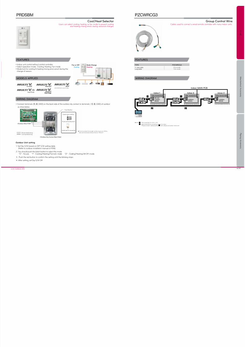
Group Control Wire
PZCWRCG3
TYPE PZCWRCG3
Y- type cable 25cm length
Long cable 9.6m length
Cables sed to connect a wred remote controller wth many ndoor nts.
odr u seg
1. Set Dp S/W based on DiP S/W settng table.(Refer to outdoor installation manual or PDB)
2. Yo shold psh the black btton to select the mode“0” : No se “1” : Coolng/Heatng/Fan lock mode “2” : Coolng/Heatng/All Off mode
3. Psh the red btton to confrm the settng ntl the blnkng stops.
4. After settng, set Dp S/W Off.
WIRING DIAGRAM
• Connect terminals (①, ②, GND) on the back sde of the otdoor dry contact to termnals ( ①, ②, GND) of otdoor
as show below.
<Outdoor Main PCB>
insert wre method
Psh arrow drecton
insert wre to connector
<Outdoor Dry Contact Back Side>
Shows eld wiringConnected wrng
※Commncaton lne length can be maxmm 300m,se commncaton lne as thck as 1.25mm².
Push Button
WIRING DIAGRAM
Indoor MAIN PCB
<Wiring Diagram>
Indoor 1
Indoor terminal block
RED (12V)
YL(SIGNAL)
BR(GND)
YL(SIGNAL)
BR(GND)
YL(SIGNAL)
BR(GND)
Indoor terminal block Indoor terminal block
Indoor 2 Indoor 3
※Note Cable assembly for ndoor nts.
Cable assembly for connectng ndoor to ndoor.- Please connect cable assembly wth already connected ndoor nt.
1
12
(ARuN40GS2A needs Pi 485)

7/27/2019 2012EU ACC Viewer
http://slidepdf.com/reader/full/2012eu-acc-viewer 25/44
48 /49LG Air Conditioners 2012
V - n e t
M e c h a n i c
a l A c c e s s o r y
P i p i n g A c c e s s o r y
FEATURES
WIRING DIAGRAM
COMPONENTS
Zone Controller
ABZCA
• Controls different zones (up to 4 zones)• Maintain proper temperature of each zone• Auto variation of dampers• Auto control of fan speed
MODELS APLLIED
PARTS INCLUDED
• Ceiling Concealed Duct (High Static Pressure)
※
Refer to each model PDB for applicable models
Factory sppled :• Zone controller PCB (1EA) • Transformer (1EA) • Case (1EA) • Cover (1EA)• Main lead wires (1EA) • Screws (1EA) • Holder (4EA) • Installation manual (1EA)
Prchased locally (reference semens, honneywell)• Damper Motor • Thermostat • Damper
Ze Crl
sb pCB
ROOM1 ROOM2
ROOM3 ROOM4
t emp er at ure se ns or te mpe rat ure se ns or
t emp er at ure se ns or te mpe rat ure se ns or
1. Zone Controller PCB
2. Trans
5. Main lead wires3. Case
1
2
3
4
5
6
7
8
Array of PCB & Controllers
Indoor Unit
Thermostat #1
In case of 220V Damper,sttsch AC 24V Relay
Replay
Replay
Replay
ReplayDamper
#4
Damper#3
Damper#2
Damper#1
Thermostat #2
Thermostat #3
Thermostat #4
Outdoor Unit
* Central
Controller
* Central
Sub PCB
* Zone
Controller
Sub PCB
* RF
Remote
Controller
AC 24V
Transformer
** Main PCB
** Wired
Remote
Controller
** Display PCB
Local sourcing components
Controls ar condtonng n p to 4 zones.
7/27/2019 2012EU ACC Viewer
http://slidepdf.com/reader/full/2012eu-acc-viewer 26/44
50 /51LG Air Conditioners 2012
V - n e t
M e c h a n i c
a l A c c e s s o r y
P i p i n g A c c e s s o r y
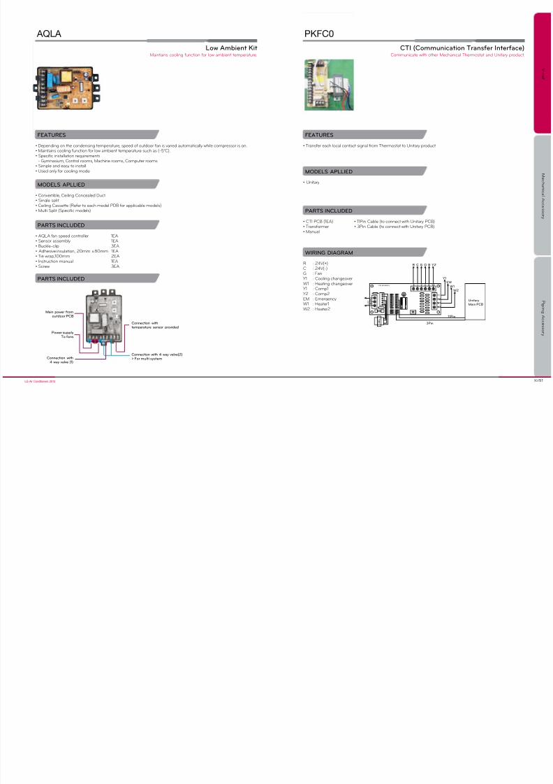
Low Ambient Kit
AQLA
FEATURES
• Depending on the condensing temperature, speed of outdoor fan is varied automatically while compressor is on.• Maintains cooling function for low ambient temperature such as (-5°C).• Specific installation requirements- Gymnasm, Control rooms, Machne rooms, Compter rooms
• Simple and easy to install• Used only for cooling mode
MODELS APLLIED
• Convertible, Ceiling Concealed Duct• Single split• Ceiling Cassette (Refer to each model PDB for applicable models)• Multi Split (Specific models)
PARTS INCLUDED
• AQLA fan speed controller 1EA• Sensor assembly 1EA• Buckle-clip 3EA• Adhesive insulation, 20mm x 80mm 1EA• Tie wrap,100mm 2EA• Instruction manual 1EA• Screw 3EA
PARTS INCLUDED
Main power romoutdoor PCB
Power supplyTo ans
Connection with4 way valve (1)
Connection withtemperature sensor provided
Connection with 4 way valve(2)> For multi system
N NL L
Mantans coolng fncton for low ambent temperatre.
CTI (Communication Transer Interace)
PKFC0
FEATURES
• Transfer each local contact signal from Thermostat to Unitary product
MODELS APLLIED
• Unitary
PARTS INCLUDED
• CTI PCB (1EA) • 11Pin Cable (to connect with Unitary PCB)• Transformer • 3Pin Cable (to connect with Unitary PCB)• Manual
WIRING DIAGRAM
R : 24V(+)C : 24V(-)G : FanY1 : Coolng changeoverW1 : Heatng changeoverY1 : Comp1
Y2 : Comp2EM : EmergencyW1 : Heater1W2 : Heater2
R
CN_AC24V(+)
2 2 0 V
3Pin
11Pin
Unitary
Main PCB
C G O B Y2
Y1
EW
W1
W2
Commncate wth other Mechancal Thermostat and untary prodct.
7/27/2019 2012EU ACC Viewer
http://slidepdf.com/reader/full/2012eu-acc-viewer 27/44
52 /53LG Air Conditioners 2012
V - n e t
M e c h a n i c
a l A c c e s s o r y
P i p i n g A c c e s s o r y
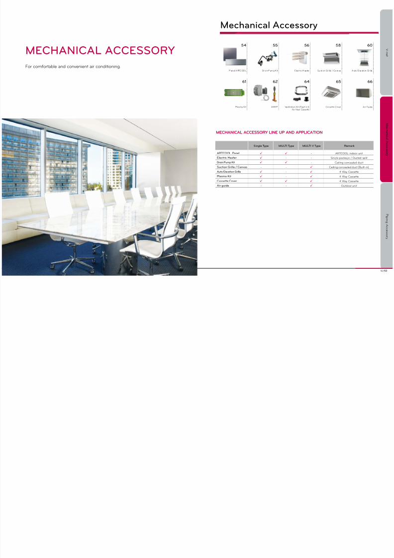
For comfortable and convenent ar condtonng.
MECHANICAL ACCESSORY
Mechanical Accessory
mECHAniCAL ACCESSoRy LinE up AnD AppLiCAtion
54 55 56 58 60
P an el A RTC OO L Dr a n P m p K t E lect r c H ea ter S ct on Gr l le / Ca nv as A to El ev at on Gr l le
61 62 64 65 66
Plasma Kt AWHP Ventlaton Kt (Fresh kt)for New Cassette
Cassette Cover Ar Gde
Single Type MULTI Type MULTI V Type Remark
ARTCOOL Panel - ARTCOOL ndoor nt
Electric Heater - - Sngle package / Dcted splt
Drain Pump Kit - Celng concealed dct
Suction Grille / Canvas - - Ceiling concealed duct (Built-in)
Auto Elevation Grille - 4 Way Cassette
Plasma Kit - 4 Way Cassette
Cassette Cover 4 Way Cassette
Air guide - - Otdoor nt
7/27/2019 2012EU ACC Viewer
http://slidepdf.com/reader/full/2012eu-acc-viewer 28/44
54 /55LG Air Conditioners 2012
V - n e t
M e c h a n i c
a l A c c e s s o r y
P i p i n g A c c e s s o r y
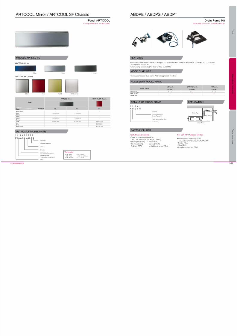
Panel ARTCOOL
ARTCOOL Mirror / ARTCOOL SF Chassis
MODELS APPLIED TO
DETAILS OF MODEL NAME
ARTCOOL SF Chassis
ARTCOOL Mirror
Silver Red Gold White silver
Blue Silver Mirror
1 2 3 4 5 6 7 8 9
P S A P V C W 1 0
Sngle splt wall
monted ar condtoner
Nmber of panel
Seral no.
Color *
Chasss
ARTCOOL front panel
Parts
Type
ARTCOL Mirror ARTCOL SF chassis
SE S8 SF
White wood - - -
Blue PSAPECB10 PSAP8CB10 -
Wood - - -
Metal - - -
Mirror PSAPECR10 PSAP8CR10 -
Cherry - -
Silver PSAPECV10 PSAP8CV10 PSAPFCV11
Red - - PSAPFCE11
Gold - - PSAPFCG11White Silver - - PSAPFCH11
ChassisColor
* Panel color
• CB : Blue • CG : Gold• CE : Red • CH : WhiteSilver• CR : Mirror • CV : Silver
A nqe blend of art and colors.
Drain Pump Kit
ABDPE / ABDPG / ABDPT
FEATURES
• In some places where natural drainage is not possible drain pump is very useful to pumps out condensedwater from ndoor nt.
• Drain pump assembly (AC 220~240V, 50/60Hz)
MODELS APLLIED
• Ceiling concealed duct (refer PDB for applicable models)
DETAILS OF MODEL NAME
PARTS INCLUDED
For G/H/R/T Chassis Models :
• Drain pump assembly (1EA)(AC 220~240V,50/60Hz,400CMM)
• Screw (4EA)• Cap (1EA)• Installation manual (1EA)
For E Chassis Models :
• Drain pump assembly (1EA)(AC 220~240V,50/60Hz,400CMM)
• Elbow (ø32)(1EA) • Hose (1EA)• Tie wrap (2EA) • Screw (10EA)• Rubber (1EA) • Installationmanual (1EA)
Drain Pipe
Drain Pump
1/50~1/1001/50~1/100
MAX 700mm
1 2 3 4 5
A B D P G
Chasss
Accessory nameDran Pmp Kt
Celng concealed dct
Accessory
APPLICATION
ACCESSORY MODEL NAME
Model NameE Chassis G/H/R Chassis T Chassis
ABDPE ABDPG ABDPT
MULTI V Type Defalt Defalt Defalt
MULTI Type
Single Type -
Effectvely drans ot condensed water.

7/27/2019 2012EU ACC Viewer
http://slidepdf.com/reader/full/2012eu-acc-viewer 29/44
56 /57LG Air Conditioners 2012
V - n e t
M e c h a n i c
a l A c c e s s o r y
P i p i n g A c c e s s o r y
Electric Heater
Single Package : LKAEH, AKEH
Ducted Split : ANEH
FEATURES
• Provides quick and additional heating.
MODELS APPLIED TO
• Single package• Ducted split (refer PDB for applicable models)
Single Package Ducted Split
PARTS SUPPLIED
Single Package
• Electric heater (1EA)• Installation manual (1EA)• Heater control box (1EA)• Screws
Ducted Split
• Electric heater (1EA )• Hexagonal nut (6EA)• Hexagonal bolt M6, L14 (16EA)• Installation Manual (1EA)
50 / 60Hz
DETAILS OF MODEL NAME
1 2 3 4 5 6 7 8 9
L K A E H 0 5 2 L
L : Large capacty heater
Voltage
Heater (kW)
Accessory name
EH : Electrc heater
Accessory
ProdctLK : Sngle packageLN : Dcted splt
2-1ø 220B
B-3ø 220B
8-3ø 380B
ACCESSORY MODEL NAME AND ELECTRICAL DATA
Single Package
TonModelName
HeaterOutput(kW)Min/Max.Volts
HeaterRating(kW)
ControlStages
Voltage(V/ø)
Standard indoor an motor Over size indoor motor
M.C.A M.F.S M.C.B M.C.A M.F.S M.C.B
3~5RT LKAEH052 3.6/5.0 5 1 208~240/1 27.6/32.2 60/60 60/60 27.6/32.2 60/60 60/60
3~5RT LKAEH102 7.2/10.0 10 1 208~240/1 47.7/55 60/60 60/60 47.7/55 60/60 60/60
6.25~17.5RT LKAEH18B 15.6/18.0 18 1 208~240/3 5 6. 2/ 64. 8 6 0/ 60 60/60 56.2/64.8 60/60 60/60
15~17.5RT LKAEH36B 31.2/36.0 18+18 2 208~240/3 97.1/112.1 125/125 125/125 97.1/112.1 125/125 125/125
20~25RT LKAEH36BL 31.2/36.0 36 2 208~240/3 97.1/ 112.1 125/125 125/125 97.1/112.1 125/125 125/125
6.25~12.5RT LKAEH098 7.5/9.0 9 1 380~415/3 26.0/27.2 60/60 60/60 31.0/32.2 60/60 60/60
7.5~17.5RT LKAEH188 15.1/18.0 18 1 380~415/3 37.5/39.5 60/60 60/60 42.5/44.5 60/60 60/60
20~25RT LKAEH368L 30.2/36.0 36 2 380~415/3 108.6/160.4 1 50/ 15 0 1 50/ 15 0 114.6/136.4 1 50/ 15 0 1 50/ 15 0
* MCA : Minimum current ampere / MFS : Maximum fuse size / MCB : Maximum circuit breaker
Ducted Split
TonModelName
HeaterOutput(kW)Min/Max.Volts
HeaterRating(kW)
ControlStages
Voltage(V/ø)
Standard indoor an motor Over size indoor motor
M.C.A M.F.S M.C.B M.C.A M.F.S M.C.B
3~5RT ANEH0521A 3.6/5.0 5 1 208~240/1 27.6/32.2 60/60 60/60 27.6/32.2 60/60 60/60
3~5RT ANEH1021A 7.2/10.0 10 1 208~240/1 47.4/55 60/60 60/60 47.7/55 60/60 60/60
6.25~12.5RT ANEH09B1B 7.8/9.0 9 1 208~240/3 30.4/35.1 60/60 60/60 30.4/35.1 60/60 60/60
6.25~17.5RT ANEH18B1B 15.6/18.0 18 1 208~240/3 50.9/58.7 70/70 70/70 50.9/58.7 70/70 70/70
15~20RT ANEH18B1C 15.6/18.0 18 1 208~240/3 56.2/64.8 70/70 70/70 62.4/72.0 80/80 80/80
15~20RT ANEH3682C 36.0 18+18 2 380~415/3 72/86.4 90 90 72/86.4 90/90 90/90
* MCA : Minimum current ampere / MFS : Maximum fuse size / MCB : Maximum circuit breaker
Provdes heatng to keep yo warm.
7/27/2019 2012EU ACC Viewer
http://slidepdf.com/reader/full/2012eu-acc-viewer 30/44
58 /59LG Air Conditioners 2012
V - n e t
M e c h a n i c
a l A c c e s s o r y
P i p i n g A c c e s s o r y
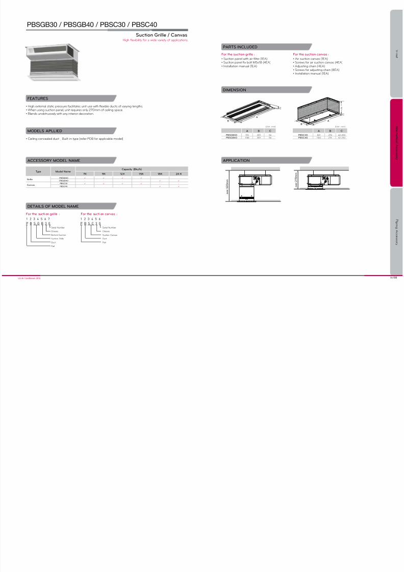
FEATURES
• High external static pressure facilitates unit use with flexible ducts of varying lengths.• When using suction panel, unit requires only 270mm of ceiling space.• Blends unobtrusively with any interior decoration.
MODELS APLLIED
• Ceiling concealed duct _ Built-in type (refer PDB for applicable model)
Suction Grille / Canvas
PBSGB30 / PBSGB40 / PBSC30 / PBSC40
PARTS INCLUDED
For the suction grille :
• Suction panel with air filter (1EA)• Suction panel fix bolt M5x18 (4EA)• Installation manual (1EA)
For the suction canvas :
• Air suction canvas (1EA)• Screws for air suction canvas (4EA)• Adjusting chain (4EA)• Screws for adjusting chain (8EA)
• Installation manual (1EA)
ACCESSORY MODEL NAME
DIMENSION
C
AB
A
B
C
o v e r 5 2 0 m m
o v e r 2 7 0 m m
APPLICATION
Type Model NameCapacity (Btu/h)
7K 9K 12K 15K 18K 24 K
GrillePBSGB30 - -
PBSGB40 - - - -
CanvasPBSC30 - -
PBSC40 - - - -
DETAILS OF MODEL NAME
1 2 3 4 5 6 7
P B S G B 3 0
Seral Nmber
Chasss
Bottom Suction
Scton Grlle
Dct
Part
1 2 3 4 5 6
P B S C 3 0
Seral Nmber
Chasss
Scton Canvas
Dct
Part
For the sucti on gril le : For the sucti on canvas :
A B C
PBSGB30 910 359 56
PBSGB40 1188 359 56
(unt : mm)
A B C
PBSC30 821 274 42-250
PBSC40 1100 274 42-250
(unt : mm)
Hgh flexblty for a wde varety of applcatons.
7/27/2019 2012EU ACC Viewer
http://slidepdf.com/reader/full/2012eu-acc-viewer 31/44
60 /61LG Air Conditioners 2012
V - n e t
M e c h a n i c
a l A c c e s s o r y
P i p i n g A c c e s s o r y
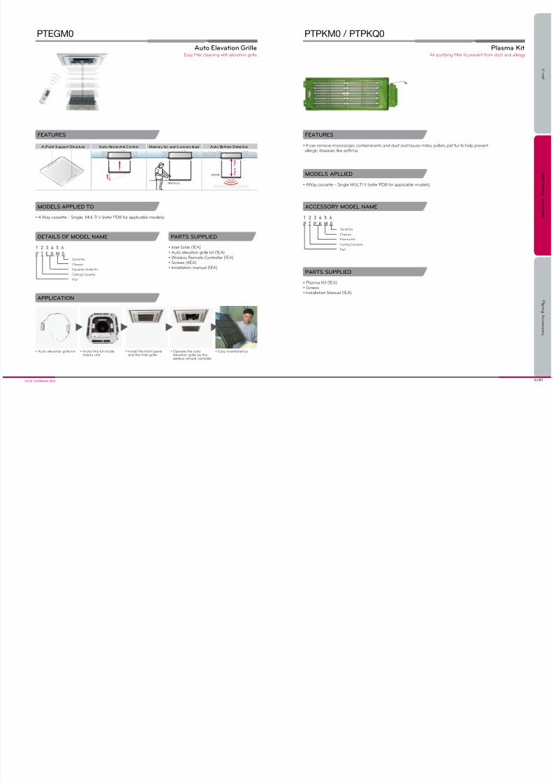
Auto Elevation Grille
PTEGM0
FEATURES
• It can remove microscopic contaminants and dust and house mites, pollen, pet fur to help preventallergc dseases lke asthma.
MODELS APPLIED TO
• 4 Way cassette - Single, MuLTi V (refer PDB for applicable models)
MODELS APLLIED
• 4Way cassette - Single MULTI V (refer PDB for applicable models)
• Plasma Kit (1EA)• Screws
• Installation Manual (1EA)
PARTS SUPPLIED
Plasma Kit
PTPKM0 / PTPKQ0
DETAILS OF MODEL NAME
1 2 3 4 5 6
P T E G M 0
Seral No.
Chasss
Elevaton Grlle Kt
Celng Cassette
Part
PARTS SUPPLIED
• Inlet Grille (1EA)• Auto elevation grille kit (1EA)• Wireless Remote Controller (1EA)• Screws (4EA)• Installation manual (1EA)
ACCESSORY MODEL NAME
1 2 3 4 5 6
P T P K M 0
Seral No.
Chasss
Plasma Kt
Celng Cassette
Part
FEATURES
4-Point Support Structure Auto Horizontal Control Memory or user’s access leve l Auto Bottom Detection
Memory
STOP
M a x . 4 . 5 m
APPLICATION
• Auto elevation grille kit • Install the kit insidendoor nt
• Install the front paneland the inlet grlle
• Operate the autoelevaton grlle by thewreless remote controller
• Easy maintenance
Easy flter cleanng wth elevaton grlle. Ar prfyng flter to prevent from dst and allergy.

7/27/2019 2012EU ACC Viewer
http://slidepdf.com/reader/full/2012eu-acc-viewer 32/44
62 /63LG Air Conditioners 2012
V - n e t
M e c h a n i c
a l A c c e s s o r y
P i p i n g A c c e s s o r y
THERMA V Kit
Sanitary Tank Kit
FEATURES
FEATURES
To nterface solar-thermal system wth splt-type THERMA V and doble col santary tank.installed at the water ppe, between santary tank and solar-thermal system.Dmenson(mm) (HxWxD) : 110x55x22
Easy to install the sanitary water tank for monobloc. There is a MCCB to protect the product.Dmenson(mm) (HxWxD) : 250x170x110Weght(kg) : 2.1
To extend THERMA V fnctonalty n generatng domestc hot water.Only appled to splt-type THERMA V.
※To be nstalled nsde THERMA V ndoor nt.
Components : THERMA V System, PHLTA, and Field-supplied items.
MODELS APPLIED TO
Components : THERMA V System, PHLTA, PHLLA, and Field-supplied items.
APPLICATION
Solar Heating Kit
PHLLA
PHLTA PHLTB
Out do or I nd oor
Fan Col unt
SantaryWaterTank
Floor Heatng Loop Radator
Otdoor unt
indoor unt
Hot Water
Cty Water
High Tempera ture Room Thermosta t(Fie ld supply)
Motorized2waycontrolvalve(Field supply)
Motorized3waycontrolvalve
(Field supply)
By-passvalve(Field supply)
LowTemperature
Shut-offvalve
SantaryWaterTank
Otdoor unt
indoor unt
Outdo or I nd oo r
Fan Col unt
Solar HeatSorce
F loor Heatng Loop RadatorHot Water
Cty Water

7/27/2019 2012EU ACC Viewer
http://slidepdf.com/reader/full/2012eu-acc-viewer 33/44
64 /65LG Air Conditioners 2012
V - n e t
M e c h a n i c
a l A c c e s s o r y
P i p i n g A c c e s s o r y
Ventilation Kit (Fresh Kit) or New Cassette
PTVK410 / PTVK420 / PTVK430
FEATURES FEATURES
• Specially designed for indoor unit.• Covers the side area of cassette.• Gives elegant looks.• Light weight.• Suitable when false ceiling is unavailable.
• Installation Bracket• Bolt• Screw• Installation manual
• Ceiling Cassette - 4Way (TP, TN, TM)
MODELS APPLIED TO
• Ceiling cassette - 4Way (TD, TD1, TH, TP, TN, TM, TQ, TR)
MODELS APPLIED TO
• Cover A (4EA), Cover B (4EA)• Cover C (4EA), Cover D (4EA)• Screws• Installation Manual (1EA)
PARTS SUPPLIED
DIMENSION
Cassette Cover
PTDCD / PTDCD1 / PTDCM / PTDCQ
PTVK410 PTVK430PTVK420
1 3 4
55mm
4 3
5
4 4
3
8 4
0
406
419
840
8 1
ACCESSORY MODEL NAME
Fresh ar can be sppled from otsde throgh ths ventlaton kt. Ar prfyng flter to prevent from dst and allergy.
Model Name Front PanelWeight(kg) Dimension(mm)
NET Gross W H D
PTDCD PT-CD0, PT-CD1, PT-HD0, PT-HD1 5 7.8 570 625 350
PTDCD1 PT-CDA1, PT-CDC1, PT-HDA1, PT-HDC1 5 7.8 570 625 350
PTDCM PT-uMC 5.9 8.8 815 495 250
PTDCQ PT-uQC 4.5 6.7 495 445 240
ASSEMBLY DIAGRAM
7/27/2019 2012EU ACC Viewer
http://slidepdf.com/reader/full/2012eu-acc-viewer 34/44
66 /67LG Air Conditioners 2012
V - n e t
M e c h a n i c
a l A c c e s s o r y
P i p i n g A c c e s s o r y
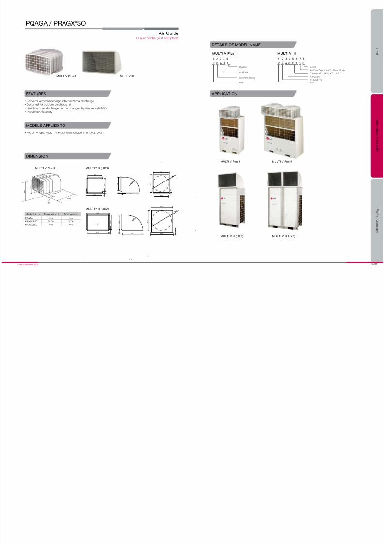
Air Guide
PQAGA / PRAGX*SO
DETAILS OF MODEL NAME
FEATURES
• Converts vertical discharge into horizontal discharge.• Designed for outdoor discharge air.• Direction of air discharge can be changed by simple installation.• Installation flexibility
• MULTI V type, MULTI V Plus II type, MULTI V III (UX2, UX3)
MODELS APPLIED TO
APPLICATION
DIMENSION
MULTI V Plus II MULTI V III
3 9 0
3 7 2 . 5
723.5
125
564
5 1 2
4 5632
7
7
33
5 1 2 R
6 0 0
50
7
7
652
618
6 5 2
570
7
7
5 0
6 0 0
5 0 0
5 0 0
R 6 0 0
7
832
900
760
7
4 5
5 0
7
7
832
7 6 2
904 4 5
7 1 8
MULTI V III (UX3)MULTI V Plus II
MULTI V III (UX2)
1 2 3 4 5
P Q A G A
Chasss
Ar Gde
Common usng
Part
1 2 3 4 5 6 7 8
P R A G X 3 S O
Seral
Air Flow Direction / S : Basic Model
Chasss X3 : uX3 / X2 : uX2
Ar Gde
R : MuLTi V
Part
muLti V pls ii muLti V iii
MULTI V III (UX3)MULTI V III (UX2)
MULTI V Plus II MULTI V Plus II
Easy ar dscharge at odd places
Model Name Gross Weight Met Weight
PQAGA 6kg 5kg
PRAGX2S0 22.5kg 12.3kg
PRAGX3S0 17kg 9.4kg

7/27/2019 2012EU ACC Viewer
http://slidepdf.com/reader/full/2012eu-acc-viewer 35/44
68 /69LG Air Conditioners 2012
For easy nstallaton and servce.
PIPING ACCESSORY
Piping Accessory
V - n e t
M e c h a n i c a l A c c e s s o r y
P i p i n g A c c e s s o r y
pipinG ACCESSoRy LinE up AnD AppLiCAtion
70 72 74 75 76
Y Branch & Header Branch(Synchro) Branch Dist ributor Y Branch & Branch Kit(MuLTi Fdx) Refrgerant chargng Kt Stopper Valve
78 80 81 82
Heat Recovery unt Dran Hose Dran pan Y Branch & HeaderBranch(MULTI V)
Synchro MULTI MULTI V Remark
Y Branch and HeaderBranch(Synchro) - Synchro
Branch Distributor(MULTI)
- - - MuLTi Fdx
Heat Recovery Unit - - MuLTi V Sync ii /
MuLTi V iii Heat Recovery
Y Branch and Branch Kit(MULTI)
- - MuLTi Fdx
Y Branch and Header Branch(MULTI V)
- - MuLTi V Heat Pmp / Heat Recovery
MuLTi V Space / MuLTi V Mn

7/27/2019 2012EU ACC Viewer
http://slidepdf.com/reader/full/2012eu-acc-viewer 36/44
70 /71LG Air Conditioners 2012
V - n e t
M e c h a n i c a l A c c e s s o r y
P i p i n g A c c e s s o r y
Connectable o Indoor Units Models Gas pipe Liquid pipe
2 Units PMUB 11A
3 Units PMUB 111A
4 Units PMUB 1111A
Y Branch and Header Branch (Synchro)
PMUB11A (2units) /
PMUB111A (3units) / PMUB1111A (4units)
FEATURES
ACCESSORY MODEL NAME
• Various Y-branch pipe of different capacities make installation much easier.• Y-branch and header branch for both gas and liquid are provided.• Insulation material is also provided for covering the branches.
• Synchro
MODELS APPLIED TO
PIPING DIAGRAM
Gas Pipe Liquid Pipe
2 branch 3 branch 4 branch
Refrgerant dstrbton channel
(1:1) (1:1)
(1:1:1) (1:1:1)
(1:1:1:1) (1:1:1:1)

7/27/2019 2012EU ACC Viewer
http://slidepdf.com/reader/full/2012eu-acc-viewer 37/44
72 /73LG Air Conditioners 2012
V - n e t
M e c h a n i c a l A c c e s s o r y
P i p i n g A c c e s s o r y
Branch Distributor (Distributor Box)
PMBD3620 / PMBD3630 / PMBD3640
FEATURES
SPECIFICATION
• Distribution of refrigerant to various indoor units.• 3 models (2, 3, 4 indoor units)• Consists of LEVs inside it• Controlling PCB inside the unit• Internally insulated (prevents any chances of drainage)• Flare joints for easy and clean installation• Compact design (low height)• Flexible installation
MODELS APPLIED TO
INSTALLATION
PARTS SUPPLIED
PMBD3620 PMBD3630 PMBD3640
No brazng Jst flarng
• systems(refer PDB for applicable models)
• Position of branch distributor in the system• PDB (Select) - Installation PDB
• BD(Banch Distributor) unit (1EA)• Hanger metal (4EA)• Screws (8EA)• Installation Manual (1EA)
DETAILS OF MODEL NAME
1 2 3 4 5 6 7 8 9
P M B D 5 4 2 0 L
L : R-22None : R410A
Seral nmber
Nmber of ndoor ntsconnectable
Maxmm capacty
Branch distributor
MuLTi
Parts
Effectve and nqe way of refrgerant dstrbton
PMBD3620 PMBD3630 PMBD3640
C onnectab le N um ber o I nd oo r uni t 1~2 1~3 1~4
Capacity (Btu/hr) 5k/7k/9k/12k/18k/24k 5k/7k/9k/12k/18k/24k 5k/7k/9k/12k/18k/24k
Casing color Pantngless Pantngless Pantngless
Power source1ø, 50/60Hz, 1ø, 50/60Hz, 1ø, 50/60Hz,
220~240/220В 220~240/220В 220~240/220В
Power consumption (W) 10 10 10
Running current (A) 0.05 0.05 0.05
Dimens ions (W x H x D) (mm) 302x143x252 302x143x252 302x143x252
Packing dimension (W x H x D) (mm) 422x202x300 422x202x300 422x202x300
Net weight 4.8 4.9 5.0
Connecting cableIndoor unit No. x mm² 4x0.75 4x0.75 4x0.75
Outdoor unit No. x mm² 4x0.75 4x0.75 4x0.75
Piping connection(Outdoor unit)
liquid (mm) 9.52 9.52 9.52
Gas (mm) 19.05 19.05 19.05
Piping connection(Indoor unit)
Liquid (mm) 6.35x2 6.35x3 6.35x4
Gas (mm) 9.52x2 9.52x3 9.52x4
Parts
Hanger (EA) 4 4 4
Screw (EA) 8 8 8
Manual (EA) 1 1 1
(R410A)

7/27/2019 2012EU ACC Viewer
http://slidepdf.com/reader/full/2012eu-acc-viewer 38/44
74 /75LG Air Conditioners 2012
V - n e t
M e c h a n i c a l A c c e s s o r y
P i p i n g A c c e s s o r y
FEATURES
• Y Branch and Branch kit make MuLTi Fdx nstallaton mch easer.• Y-Branch and Branch kit for both gas and liquid are provided.• Insulation material is also provided for covering the branches.
APPLICATION
• Y Branch for Gas side and Liquid side (1 set)• Installation manual (1EA)
PARTS SUPPLIED
Y Branch and Branch Kit ( )
PMBL3620 / PMBL5620 (2units)
PMBL1203F0 (3units)
1ø, 3ø
MODELS APPLIED TO
Refrgerant dstrbton channel
ACCESSORY MODEL NAME
Model Name No. o BD units Applicable ModelSpeciication
Gas Liquid
PMBL3620 2 nts Only 3ø, 36k Btu/h
PMBL5620 2 nts 1ø, 3ø
PMBL1203F0 3 nts 1ø, 3ø
Ø15.88 Ø15.88
Ø15.88
.3 .3
.3
. .
.
. .
.
. .
.
.3 .3
.3
Ø19.05 Ø19.05
Ø19.05
. .
.
. .
.
.3 .3
.3
. .
.
Ø9.52 Ø9.52
Ø9.52
. .
.
Ø6.35 Ø6.35
Ø6.35
. .
.
. .
.
Ø .Ø19.05
.Ø9.52.
Ø9.52
(unt : mm)
Rerigerant charging Kit
PRAC1
PROCEDURE
• Arrange manifold, capillary assembly, refrigerant vessel and scale• Connect manifold to the gas pipe service valve of outdoor uint as shown in the figure.• Connect manifold and capillary tube. Use designated capillary assembly only.
if desgnated capllary assembly sn’t sed, the system may get damaged.• Connect capillary and refrigerant vessel.• Purge hose and manifold.• After “568” s dsplayed, open the valve and charge the refrgerant
MODELS APPLIED TO
133
6 9
202
* Falt Detect & Dagnoss
Manfold
Capllary Assembly
Refrgerant
• “329” : Temperatre Range Error (in case that ndoor nt or otdoor nt s ot of range)• “339” : Low Pressre Descent Error (in case the system rns at low pressre lmt for over 10 mntes)
• “349” : Rapd refrgerant nflow (in case the lqd refrgerant flows n becase of not sng desgnated capl-lary assembly)• “359” : instablty Error (in case the hgh/low pressre target doesn’t get satsfed for some tme after the startng operaton)
ERROR CONTENTS ABOUT AUTO REFRIGERANT CHARGING FUNCTION
DIMENSION
To recharge refrgerant after a pmp down or when refrgerant s ether nsffcent or excessve.

7/27/2019 2012EU ACC Viewer
http://slidepdf.com/reader/full/2012eu-acc-viewer 39/44
76 /77LG Air Conditioners 2012
V - n e t
M e c h a n i c a l A c c e s s o r y
P i p i n g A c c e s s o r y
Spec
PRVT120
PRVT780
PRVT980
Stopper Valves
PRVT120 under 1/2 (inch)
PRVT780 under 7/8 (inch) / PRVT980 under 9/8 (inch)
FEATURES
SPECIFICATION
USAGE
• This unit can be applied for the additional indoor unit’s installation.• This unit can be applied for each indoor unit’s service
• In case of installation of additional indoor unit, refrigerant of used indoor unit must be discharged.(Room3 & Room4)• If stopper valve is already installed, you can install additional indoor unit without refrigerant loss from the entire system.• After installation of additional indoor unit, you just need refrigerant charging for “A” section.• Then, open the Stopper Valve.
case1(room3, 4 s sed. room1, 2 need to nstall ndoor nt)
※Stopper Valve s already nstalled
Room4
Room3
Room2
Room1
9.52 : 19.05
9.52 : 19.05
3.0m
3.0m
3.0m
10.0m
5.0m
9.52 : 15.88
9.52 : 15.88
6.35 : 12.7
"A"
Closed state
Stopper valvesI
.
I
I
.
I
.
I
I
.
Room1
Room2
Room3
10.0m
3.0m
3.0m
3.0m
3.0m
9.52 : 15.88
6.35 : 12.7
9.52 : 15.88
9.52 : 19.05
9.52 : 19.05
Stopper ValvesOpen state
Open/close portCharge port
INSTALLATION
- When weldng, servce valve shod be wrapped by wet cloth.
1. Ct nlet sde of the connector,and weld the ppe
2. in case of the nstallaton ofaddtonal ndoor nt, otletsde connector shold be ctaccordng to nstallaton ppe.
3. in case of nstallaton of stop-per valve, flare part sholdbe facng towards addtonalndoor nt.
4. in case of nstallaton of add-tonal ndoor nt, SVC valveshold be n closed state

7/27/2019 2012EU ACC Viewer
http://slidepdf.com/reader/full/2012eu-acc-viewer 40/44

7/27/2019 2012EU ACC Viewer
http://slidepdf.com/reader/full/2012eu-acc-viewer 41/44
80 /81LG Air Conditioners 2012
V - n e t
M e c h a n i c a l A c c e s s o r y
P i p i n g A c c e s s o r y
Drain Hose
PHDHA05T / PHDHA07T
PHDHA05B / PHDHA07B
PROCEDURE USAGE
Ths nt can be appled for otdoor nt’s dranit redces the nstallaton tme by over 40% wth elbow-less dran hose.Mdget dran pmp covers maxmm 800mm hgh, featrng easy ppng nstallaton.
STANDARD INSTALLATION
Drain Pan
PRODX20 / PRODX30
Models applied to Ceiling Cassette, Ceiling Concealed Duct. (refer PDB for applicable model.)
• This unit does not cover water drops of the outside product• Connect drain hose to drain pipe for drain condensate
Dran Ppe
Servce Valve
Tck dran pan below base pan
※in case of the nstallaton of dran pan, dran ppe shold be located below the SVC valve.
Psh dran pan n the drecton of the arrow.Brackets can be fixed on the side panel
Easy dran nstallaton installed to dran water from a MuLTi V iii otdoor nt.
ACCESSORY MODEL NAME
Model Name Length Quantity
PHDHA05T 500mm 30EA
PHDHA07T 700mm 30EA
PHDHA05B 500mm 5EA
PHDHA07B 700mm 5EA
MODEL NAME
Model L Remark
PRODX20 920mm uX2
PRODX30 1240mm uX3
Max. 450
250Flexble HoseMake a loop form
1 Way, 4Way Ceiling Cassette,
Concealed Duct(with drain pump)
(unt : mm)

7/27/2019 2012EU ACC Viewer
http://slidepdf.com/reader/full/2012eu-acc-viewer 42/44
82 /83LG Air Conditioners 2012
V - n e t
M e c h a n i c a l A c c e s s o r y
P i p i n g A c c e s s o r y
Models Gas pipe Liquid pipe
4 branch / ARBL054(under 22.4kW)
7 branch / ARBL057(under 22.4kW)
4 branch / ARBL104(under 44.8kW)
7 branch / ARBL107(under 44.8kW)
10 branch / ARBL1010(under 44.8kW)
10 branch / ARBL2010(under 95.2kW)
Y Branch and Header Branch ( )
Header Branch / Y Branch
FEATURES
ACCESSORY MODEL NAME
MODELS APPLIED TO
• Various Y-branch pipe of different capacities make MULTI V installation much eas ier.• Y-branch and header branch for both gas and liquid are provided.• Insulation material is also provided for covering the branches.
Header Branch Y Branch
•
•
•
•
••
• •
• •
PIPING DIAGRAM
Header Branch
Otdoor nt
Y- branch
• R410A
Header Branch
(unt : mm)
For refrgerant dstrbton of ndoor nts.

7/27/2019 2012EU ACC Viewer
http://slidepdf.com/reader/full/2012eu-acc-viewer 43/44

7/27/2019 2012EU ACC Viewer
http://slidepdf.com/reader/full/2012eu-acc-viewer 44/44