2012 Toyota Highlander Owners Manual
604
622 Abbreviation list Abbreviation/Acronym list ABBREVIATIONS MEANING 2WD 2 Wheel Drive 4WD 4 Wheel Drive A/C Air Conditioning ABS Anti-lock Brake System ACC Accessory AI-SHIFT Artificial Intelligence Shift control ALR Automatic Locking Retractor CRS Child Restraint System DAC Downhill Assist Control DISP Display ECU Electronic Control Unit EDR Event Data Recorder ELR Emergency Locking Retractor EPS Electric Power Steering GAWR Gross Axle Weight Rating GCWR Gross Combination Weight Rating GVWR Gross Vehicle Weight Rating I/M Emission Inspection and Maintenance LATCH Lower Anchors and Tethers for Children LED Light Emitting Diode MMT Methylcyclopentadienyl Manganese Tricarbonyl MTBE Methyl Tertiary Butyl Ether
-
Upload
aatifsaif80 -
Category
Documents
-
view
283 -
download
3
Transcript of 2012 Toyota Highlander Owners Manual

Abbreviation list
Abbreviation/Acronym list
ABBREVIATIONS MEANING
2WD 2 Wheel Drive
4WD 4 Wheel Drive
A/C Air Conditioning
ABS Anti-lock Brake System
ACC Accessory
AI-SHIFT Artificial Intelligence Shift control
ALR Automatic Locking Retractor
CRS Child Restraint System
DAC Downhill Assist Control
DISP Display
ECU Electronic Control Unit
EDR Event Data Recorder
ELR Emergency Locking Retractor
EPS Electric Power Steering
GAWR Gross Axle Weight Rating
GCWR Gross Combination Weight Rating
GVWR Gross Vehicle Weight Rating
I/M Emission Inspection and Maintenance
LATCH Lower Anchors and Tethers for Children
LED Light Emitting Diode
MMT Methylcyclopentadienyl Manganese Tricarbonyl
MTBE Methyl Tertiary Butyl Ether
622

Abbreviation list
OBD On Board Diagnostics
SRS Supplemental Restraint System
TIN Tire Identification Number
TPMS Tire Pressure Warning System
TRAC Traction Control
TWR Trailer Weight Rating
VIN Vehicle Identification Number
VSC Vehicle Stability Control
ABBREVIATIONS MEANING
623

For your information
Main Owner’s Manual
Please note that this manual covers all models and all equipment, includingoptions. Therefore, you may find some explanations for equipment notinstalled on your vehicle.
All specifications provided in this manual are current at the time of printing.However, because of the Toyota policy of continual product improvement, wereserve the right to make changes at any time without notice.
Depending on specifications, the vehicle shown in the illustrations may differfrom your vehicle in terms of equipment.
Noise from under vehicle after turning off the engine
Approximately five hours after the engine is turned off, you may hear soundcoming from under the vehicle for several minutes. This is the sound of a fuelevaporation leakage check and, it does not indicate a malfunction.
Accessories, spare parts and modification of your Toyota
A wide variety of non-genuine spare parts and accessories for Toyotavehicles are currently available on the market. You should know that theseparts are not covered by Toyota warranty and that Toyota is not responsiblefor their performance, repair, or replacement, or for any damage they maycause to, or adverse effect they may have on, your Toyota vehicle.
This vehicle should not be modified with non-genuine Toyota products.Modification with non-genuine Toyota products may affect performance,safety or durability, and may even violate governmental regulations. Inaddition, damage or performance problems resulting from the modificationmay not be covered under warranty.
24

Installation of a mobile two-way radio system
The installation of a mobile two-way radio system in your vehicle could affectelectronic systems such as:
●Multiport fuel injection system/sequential multiport fuel injection system
●Cruise control system
●Anti-lock brake system
●SRS airbag system
●Seat belt pretensioner system
Be sure to check with your Toyota dealer for precautionary measures or spe-cial instructions regarding installation of a mobile two-way radio system.
Scrapping of your Toyota
The SRS airbag and seat belt pretensioner devices in your Toyota containexplosive chemicals. If the vehicle is scrapped with the airbags and seat beltpretensioners left as they are, this may cause an accident such as fire. Besure to have the systems of the SRS airbag and seat belt pretensionerremoved and disposed of by a qualified service shop or by your Toyotadealer before you scrap your vehicle.
Perchlorate Material
Special handling may apply, See www.dtsc.ca.gov/hazardouswaste/perchlorate.
Your vehicle has components that may contain perchlorate. These compo-nents may include airbag, seat belt pretensioners, and wireless remote con-trol batteries.
25

Vehicle Control and Operation Data Recording
Your Toyota is equipped with sophisticated computers that record certaininformation about your vehicle’s operation, such as:
• Engine speed• Accelerator status• Brake status• Vehicle speed• Shift positionThe data recorded varies according to the grade level and options the vehi-cle is equipped with. The computers do not record conversations, sound orpictures.
● Data usage
Toyota may use the data recorded in these computers to diagnose malfunc-tions, conduct research and development, and improve quality.
Toyota will not disclose the recorded data to a third party except:
• With the consent of the vehicle owner or with the consent of the lessee ifthe vehicle is leased
• In response to an official request by the police, a court of law or a govern-ment agency
• For research purposes where the data is not tied to a specific vehicle orvehicle owner
26

● Event data recorder
Your vehicle has computers that monitor and control certain aspects of yourvehicle. These computers assist in driving and maintaining optimal vehicleperformance.
Besides storing data useful for troubleshooting, there is an event datarecorder (EDR) that records data in a crash or near crash event.
The SRS airbag sensor assembly contains the EDR. In a crash or near crashevent, this device may record the following information:
• Engine speed• Whether the brake pedal was depressed or not• Vehicle speed• To what extent the accelerator pedal was depressed• The transmission shift position• Whether the driver and front passenger wore seat belts or not• Driver’s seat position• SRS airbag deployment data• SRS airbag system diagnostic data• Front passenger’s occupant classificationThe information above is intended to be used for the purpose of improvingvehicle safety performance. Unlike general data recorders, the EDR doesnot record sound data such as conversation between passengers.
● Disclosure of the EDR data
Toyota will not disclose the data recorded in an EDR to a third party exceptwhen:
• An agreement from the vehicle’s owner (or the leasing company for aleased vehicle) is obtained
• Officially requested to by the police or other authorities• Necessary, for use as a defense for Toyota in a lawsuit• Ordered to by a court of lawHowever, if necessary, Toyota will:
• Use the data for research on Toyota vehicle safety performance• Disclose the data to a third party for research purposes without disclosing
details of the vehicle owner, and that only when deemed necessary• Disclose summarized data cleared of vehicle identification information to a
non-Toyota organization for research purposes
27

CAUTION
■General precautions while drivingDriving under the influence: Never drive your vehicle when under the influ-ence of alcohol or drugs that have impaired your ability to operate your vehi-cle. Alcohol and certain drugs delay reaction time, impair judgment andreduce coordination, which could lead to an accident that could result indeath or serious injury.
Defensive driving: Always drive defensively. Anticipate mistakes that otherdrivers or pedestrians might make and be ready to avoid accidents.
Driver distraction: Always give your full attention to driving. Anything that dis-tracts the driver, such as adjusting controls, talking on a cellular phone orreading can result in a collision with resulting death or serious injury to you,your occupants or others.
■General precaution regarding children’s safetyNever leave children unattended in the vehicle, and never allow children tohave or use the key.
Children may be able to start the vehicle or shift the vehicle into neutral.There is also a danger that children may injure themselves by playing withthe windows, the moon roof, or other features of the vehicle. In addition, heatbuild-up or extremely cold temperatures inside the vehicle can be fatal tochildren.
28

Symbols used throughout this manual
Cautions & Notices
Symbols used in illustrations
CAUTION
This is a warning against anything which may cause death or injury to people ifthe warning is ignored. You are informed about what you must or must not doin order to reduce the risk of injury to yourself and others.
NOTICE
This is a warning against anything which may cause damage to the vehicle orits equipment if the warning is ignored. You are informed about what you mustor must not do in order to avoid or reduce the risk of damage to your Toyotaand its equipment.
Safety symbol
The symbol of a circle with a slash through it means “Do not”, “Donot do this”, or “Do not let this happen”.
Arrows indicating operations
Indicates the action (pushing, turning,etc.) used to operate switches and otherdevices.
Indicates the outcome of an operation(e.g. a lid opens).
29

30

TABLE OF CONTENTS
1
1 Before driving Adjusting and operating features such as door locks, mirrors, and steering column.
2 When driving Driving, stopping and safe-driving information.
3 Interior features
Air conditioning and audio systems, as well as other interior features for a comfortable driving experience.
4 Maintenance and care
Cleaning and protecting your vehicle, performing do-it-yourself maintenance, and maintenance information.
5 When trouble arises
What to do if the vehicle needs to be towed, gets a flat tire, or is involved in an accident.
6 Vehicle specifications Detailed vehicle information.
7 For owners Reporting safety defects for U.S. owners, and seat belt and SRS airbag instructions for Canadian owners
Index Alphabetical listing of information contained in this manual.

1-1. Key information
Keys
The following keys are provided with the vehicle.
Vehicles without smart key system (type A)
Master keysValet keyKey number plate
Vehicles without smart key system (type B)
Master keysValet keyKey number plate
Vehicles with smart key system
Electronic keys• Operating the smart key
system (→P. 35)• Operating the wireless
remote control function (→P. 48)
Mechanical keysKey number plate
32

1-1. Key information
1
Before driving
Using the mechanical key (vehicles with smart key system)
Take out the mechanical key.
After using the mechanical key,store it in the electronic key. Carrythe mechanical key together withthe electronic key. If the electronickey battery is depleted, you willneed the mechanical key. (→P. 558)
■When required to leave a key to the vehicle with a parking attendantLock the glove box as circumstances demand. (→P. 400)
Vehicles without smart key system: Carry the master key for your own useand provide the attendant with the valet key.
Vehicles with smart key system: Remove the mechanical key for your ownuse and provide the attendant with the electronic key only.
■Key number plateKeep the plate in a safe place such as your wallet, not in the vehicle. In theevent that a key is lost, a new key can be made by your Toyota dealer usingthe key number plate. (→P. 557)
■When riding in an aircraft (vehicles with smart key system)When bringing an electronic key onto an aircraft, make sure you do notpress any buttons on the electronic key while inside the aircraft cabin. If youare carrying an electronic key in your bag etc., ensure that the buttons arenot likely to be pressed accidentally. Pressing a button may cause the elec-tronic key to emit radio waves that could interfere with the operation of theaircraft.
33

1-1. Key information
NOTICE
■To prevent key damage●Do not subject the keys to strong shocks, expose them to high tempera-
tures by placing them in direct sunlight, or get them wet.
●Do not expose the keys to electromagnetic materials or attach any mate-rial that blocks electromagnetic waves to the key surface.
●Do not disassemble the key.
34

1-2. Opening, closing and locking the doors∗
1
Before driving
Smart key system
The following operations can be performed simply by carrying theelectronic key on your person, for example in your pocket.(The driver should always carry the electronic key.)
Locks and unlocks the doors (→P. 36)Starts the engine (→P. 170)Opens the glass hatch (→P. 37)Locks and unlocks the doors (→P. 36)
Electronic key
Electronic key
Electronic key
Electronic key
∗: If equipped
35
1-2. Opening, closing and locking the doors
Unlocking and locking the doors
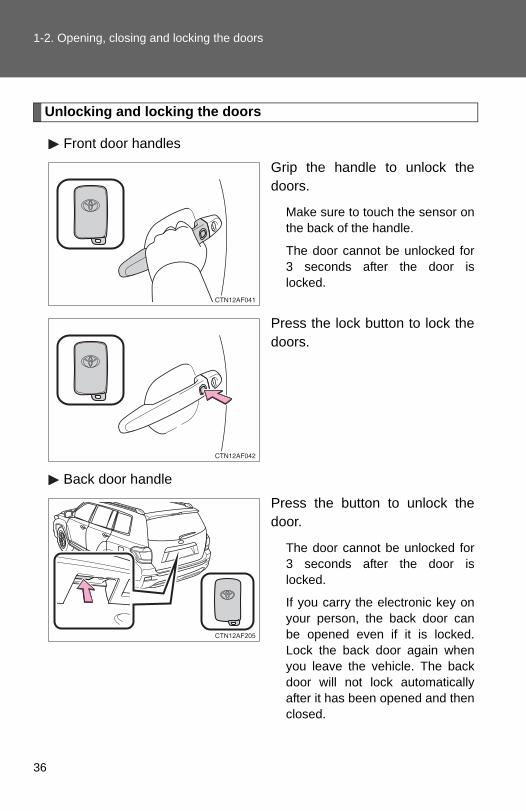
Front door handles
Grip the handle to unlock thedoors.
Make sure to touch the sensor onthe back of the handle.
The door cannot be unlocked for3 seconds after the door islocked.
Press the lock button to lock thedoors.
Back door handle
Press the button to unlock thedoor.
The door cannot be unlocked for3 seconds after the door islocked.
If you carry the electronic key onyour person, the back door canbe opened even if it is locked.Lock the back door again whenyou leave the vehicle. The backdoor will not lock automaticallyafter it has been opened and thenclosed.
36

1-2. Opening, closing and locking the doors
1
Before driving
Press the button to lock the door.
Opening the glass hatch (if equipped)
Press and hold the button toopen the glass hatch. The glasshatch will pop up.
The glass hatch can be unlockedonly when the back door isclosed.
37

1-2. Opening, closing and locking the doors
Antenna location and effective range
■ Antenna locationAntennas outside the cabinAntennas inside the cabinAntenna outside the luggagecompartment
38

1-2. Opening, closing and locking the doors
1
Before driving
■ Effective range (areas within which the electronic key isdetected)
When locking or unlockingthe doors
This system can be operatedwhen the electronic key iswithin about 2.3 ft. (0.7 m) ofeither of the outside frontdoor handles.
When starting the engineor changing “ENGINESTART STOP” switchmodes
This system can be operatedwhen the electronic key isinside the vehicle.
When opening the glasshatch and locking orunlocking the doors
This system can be operatedwhen the electronic key iswithin about 2.3 ft. (0.7 m) ofthe back door handle.
39

1-2. Opening, closing and locking the doors
■Operation signalsA buzzer sounds and the emergency flashers flash to indicate that the doorshave been locked/unlocked. (Locked: Once; Unlocked: Twice)
■Conditions affecting operationThe smart key system uses weak radio waves. In the following situations,the communication between the electronic key and the vehicle may beaffected, preventing the smart key system and wireless remote control fromoperating properly. (Ways of coping: →P. 558)
●When the electronic key battery is depleted
●Near a TV tower, electric power plant, gas station, radio station, large dis-play, airport or other facility that generates strong radio waves or electri-cal noise
●When carrying a portable radio, cellular phone, cordless phone or otherwireless communication devices
●When the electronic key is in contact with, or is covered by a metallicobject
●When multiple electronic keys are in the vicinity
●When carrying or using the electronic key together with the followingdevices that emit radio waves
• Another vehicle’s electronic key• A wireless key that emits radio waves• Personal computer
● If window tint with a metallic content or metallic objects are attached tothe rear window
■Switching the door unlock functionIt is possible to set which doors the entry function unlocks.
Turn the “ENGINE START STOP” switch OFF.
When the indicator on the key surface is turned off, push and hold
, or for approximately 5 seconds while pushing
on the key.
STEP 1
STEP 2
40

1-2. Opening, closing and locking the doors
1
Before driving
The setting changes each time an operation is performed, as shown below.(When changing the setting continuously, release the buttons, wait for atleast 5 seconds, and repeat step 2.)
To prevent unintended triggering of the alarm, unlock the doors using thewireless remote control and open and close a door once after the settingshave been changed. (If a door is not opened within 60 seconds after ispressed, the doors will be locked again and the alarm will automatically beset.)In case that the alarm is triggered, immediately stop the alarm. (→P. 116)
■Battery-saving functionIn the following circumstances, the entry function is disabled in order to pre-vent the vehicle and electronic key batteries from discharging.
●When the entry function has not been used for 2 weeks or more
●When the electronic key has been left within approximately 3 ft. (1 m) ofthe vehicle for 10 minutes or more
The system will resume operation when...
●The vehicle is locked using the door handle lock button.
●The vehicle is locked/unlocked using the wireless remote control func-tion. (→P. 48)
●The vehicle is locked/unlocked using the mechanical key. (→P. 558)
Multi-information display Unlocking doors Beep
Hold the driver's door han-dle to unlock only the driver's door. Exterior: Beeps three
timesInterior: Pings onceHold the front passenger’s
door handle to unlock all doors.
Hold either front door han-dle to unlock all doors.
Exterior: Beeps twiceInterior: Pings once
41

1-2. Opening, closing and locking the doors
■Electronic key battery depletion●The standard battery life is 1 to 2 years. (The battery becomes depleted
even if the electronic key is not used.) If the smart key system or thewireless remote control function does not operate, or the detection areabecomes smaller, the battery may be depleted. Replace the battery whennecessary. (→P. 497)
● If the battery becomes low, an alarm will sound in the cabin when theengine stops. (→P. 43)
●To avoid serious deterioration, do not leave the electronic key within 3 ft.(1 m) of the following electrical appliances that produce a magnetic field.
• TVs• Personal computers• Recharging cellular phones or cordless phones• Table lamps
■To operate the system properlyMake sure to carry the electronic key when operating the system. Do not getthe electronic key too close to the vehicle when operating the system fromthe outside of the vehicle.
Depending on the position and holding condition of the electronic key, thekey may not be detected correctly and the system may not operate properly.(The alarm may go off accidentally, or the door lock prevention may not func-tion.)
■Note for the entry function●Even when the electronic key is within the effective range (detection
areas), the system may not operate properly in the following cases.
• The electronic key is too close to the window or outside door handle,near the ground, or in a high place when the doors are locked orunlocked.
• The electronic key is on the instrument panel, luggage cover, floor or inthe glove box when the engine is started or “ENGINE START STOP”switch modes are changed.
●Do not leave the electronic key on top of the instrument panel or near thedoor pockets when exiting the vehicle. Depending on the radio wavereception conditions, it may be detected by the antenna outside the cabinand the door will become lockable from the outside, possibly trapping theelectronic key inside the vehicle.
42

1-2. Opening, closing and locking the doors
1
Before driving
●As long as the electronic key is within the effective range, the doors maybe locked or unlocked by anyone.
●Even if the electronic key is not inside the vehicle, it may be possible tostart the engine if the electronic key is near the window.
●The doors may unlock if a large amount of water splashes on the doorhandle, such as in the rain or in a car wash. (The doors will automaticallybe locked after approximately 60 seconds if the doors are not openedand closed.)
●Gripping the door handle when wearing a glove may not unlock the door.
● If the wireless remote control is used to lock the doors when the elec-tronic key is near the vehicle, there is a possibility that the door may notbe unlocked by the entry function. (Use the wireless remote control tounlock the doors.)
■When the vehicle is not driven for extended periodsTo prevent theft of the vehicle, do not leave the electronic key within 6 ft. (2m) of the vehicle.
■Security featureIf a door is not opened within approximately 60 seconds after the vehicle isunlocked, the security feature automatically locks the vehicle again.
■Alarms and warning indicatorsA combination of exterior and interior alarms as well as warning lights andwarning messages shown on the multi-information display are used toreduce the chance of vehicle theft and accidents resulting from erroneousoperation.
●When any warning lights come on:Take appropriate measures according to which warning light comes on.(→P. 528)
●When a warning message is shown on the multi-information display:Take appropriate measures according to the warning message on themulti-information display. (→P. 539)
43

1-2. Opening, closing and locking the doors
●When an alarm sounds:Take appropriate measures according to the following table.
Alarm Situation Correction procedure
Exterior alarm sounds once for 2 seconds
Tried to lock the doors using the entry function while the electronic key was still inside the passen-ger compartment.
Retrieve the elec-tronic key from the passenger compart-ment and lock the doors again.
Tried to close the glass hatch with the electronic key inside and all doors locked.
Retrieve the elec-tronic key and close the glass hatch.
Exterior alarm sounds once for 60 seconds
Tried to exit the vehicle with the electronic key and lock the doors without first turning the “ENGINE START STOP” switch OFF.
Turn the “ENGINE START STOP” switch OFF and lock the doors again.
Exterior alarm sounds once for 10 seconds
Tried to lock the vehicle using the entry function while a door was open.
Close all of the doors and lock the doors again.
Interior alarm sounds continu-ously
Tried to open the door and exit the vehicle without shifting the shift lever to P.
Shift the shift lever to P.
Interior alarm beeps repeatedly
Switched to ACCESSORY mode while the driver's door was open. (Opened the driver's door when the “ENGINE START STOP” switch was in ACCES-SORY mode.)
Turn the “ENGINE START STOP” switch OFF and close the driver's door.
Turned the “ENGINE START STOP” switch OFF while the driver's door was open.
Close the driver's door.
44

1-2. Opening, closing and locking the doors
1
Before driving
*: A message will be shown on the multi-information display.
■ If the smart key system does not operate properly●Locking and unlocking the doors: Use the mechanical key. (→P. 558)
●Starting the engine. (→P. 558)
■When the electronic key battery is fully depleted→P. 497
Alarm Situation Correction procedure
Interior and exte-rior alarms sound continuously.*
Tried to close the driver’s door after carrying the key outside the vehicle with the “ENGINE START STOP” switch in IGNITION ON or ACCESSORY mode and without the shift lever being in P.
Shift the shift lever to P, turn the “ENGINE START STOP” switch OFF and close the driver’s door again.
Interior alarm beeps once.*
The electronic key has a low battery.
Replace the electronic key battery.
Tried to start the engine without the electronic key being present, or when the electronic key was not functioning normally.
Start the engine with the electronic key present.
Interior alarm beeps once and exterior alarm sounds 3 times.*
Tried to close the driver’s door after carrying the key outside the vehicle without turning the “ENGINE START STOP” switch OFF.
Turn the “ENGINE START STOP” switch OFF and close the driver’s door again.
An occupant carried the electronic key outside the vehicle and closed the door when the “ENGINE START STOP” switch was in IGNITION ON or ACCESSORY mode.
Bring the electronic key back into the vehi-cle.
45

1-2. Opening, closing and locking the doors
■Customization that can be configured at Toyota dealerIt is possible to deactivate the smart key system etc. (Customizable features →P. 602)
■Certification for the smart key systemFor vehicles sold in the U.S.A.
FCC ID: NI4TMLF-3HYQ14AABHYQ13BZSHYQ14ABKHYQ13CZA
NOTE:This device complies with part 15 of the FCC Rules. Operation is subject tothe following two conditions: (1) This device may not cause harmful interfer-ence, and (2) this device must accept any interference received, includinginterference that may cause undesired operation.
FCC WARNING:Changes or modifications not expressly approved by the party responsiblefor compliance could void the user's authority to operate the equipment.
For vehicles sold in Canada
NOTE:Operation is subject to the following two conditions: (1) this device may notcause interference, and (2) this device must accept any interference, includ-ing interference that may cause undesired operation of the device.
46

1-2. Opening, closing and locking the doors
1
Before driving
CAUTION
■Caution regarding interference with electronic devices●People with implanted pacemakers or cardiac defibrillators should keep
away from the smart key system antennas. (→P. 38) The radio waves mayaffect the operation of such devices. If necessary, the entry function canbe disabled. Ask your Toyota dealer for details, such as the frequency ofradio waves and timing of emitting the radio waves. Then, consult yourdoctor to see if you should disable the entry function.
●Users of any electrical medical device other than implanted pacemakersand implanted cardiac defibrillators should consult the manufacturer of thedevice for information about its operation under the influence of radiowaves.Radio waves could have unexpected effects on the operation of suchmedical devices.
Ask your Toyota dealer for details for disabling the entry function.
47

1-2. Opening, closing and locking the doors
Wireless remote control
The wireless remote control can be used to lock and unlock the vehi-cle from outside the vehicle.
Vehicles without smart key system (type A)
Locks all doorsUnlocks all doors
Pressing the button unlocksthe driver’s door. Pressing thebutton again within 3 secondsunlocks the other doors.
Pushing and holding:Opens and closes thepower back doorPushing and holding:Opens the glass hatch
The glass hatch can beopened only when the backdoor is closed.
Pushing and holding:Sounds alarm
48

1-2. Opening, closing and locking the doors
1
Before driving
Vehicles without smart key system (type B)
Locks all doorsUnlocks all doors
Pressing the button unlocksthe driver’s door. Pressing thebutton again within 3 secondsunlocks the other doors.
Pushing and holding:Sounds alarmPushing and holding:Opens the glass hatch(vehicles with glass hatch)
The glass hatch can beopened only when the backdoor is closed.
Vehicles with smart key system
Locks all doorsUnlocks all doors
Pressing the button unlocksthe driver’s door. Pressing thebutton again within 3 secondsunlocks the other doors.
Pushing and holding:Opens and closes thepower back door (vehicleswith power back door)Pushing and holding:Sounds alarm
49

1-2. Opening, closing and locking the doors
■Operation signalsDoors: A buzzer sounds and the emergency flashers flash to indicate that
the doors have been locked/unlocked. (Locked: Once; Unlocked:Twice)
Back door: A buzzer sounds and the emergency flashers flash twice toindicate that the back door has been opened/closed.
■Panic mode
Vehicles without smart key system
Vehicles with smart key system
■Door lock buzzerIf a door is not fully closed, a buzzer sounds continuously if an attempt tolock the door is made. Fully close the door to stop the buzzer, and lock thevehicle once more.
When is pushed for longer thanabout one second, an alarm will sound forabout 60 seconds and the vehicle lightswill flash to deter any person from tryingto break into or damage your vehicle.
To stop the alarm, push any button on thewireless remote control.
When is pushed for longer thanabout one second, an alarm will sound forabout 60 seconds and the vehicle lightswill flash to deter any person from tryingto break into or damage your vehicle.
To stop the alarm, push any button on thewireless remote control.
50
1-2. Opening, closing and locking the doors
1
Before driving
■Key battery depletionVehicles without smart key system
The standard battery life is 1 to 2 years. (The battery becomes depletedeven if the key is not used.) If the wireless remote control function does notoperate, the battery may be depleted. Replace the battery when necessary.(→P. 496)
Vehicles with smart key system→P. 497
■ If the wireless remote control does not operate properlyVehicles without smart key system
Locking and unlocking the doors: Use the key. (→P. 54)
Vehicles with smart key system
●Locking and unlocking the doors: Use the mechanical key. (→P. 558)
●Starting the engine. (→P. 558)
■Security featureIf a door is not opened within approximately 60 seconds after the vehicle isunlocked, the security feature automatically locks the vehicle again.
■AlarmUsing the wireless remote control to lock the doors will set the alarm system. (→P. 116)
51

1-2. Opening, closing and locking the doors
■Conditions affecting operationVehicles without smart key system
The wireless remote control function may not operate normally in the follow-ing situations.
●Near a TV tower, radio station, electric power plant, airport or other facil-ity that generates strong radio waves
●When carrying a portable radio, cellular phone or other wireless commu-nication device
●When multiple wireless keys are in the vicinity
●When the wireless key is in contact with, or is covered by a metallicobject
●When a wireless key (that emits radio waves) is being used nearby
●When the wireless key has been left near an electrical appliance such asa personal computer
Vehicles with smart key system→P. 40
■Customization that can be configured at Toyota dealerSettings (e.g. wireless remote control) can be changed. (Customizable features →P. 602)
■Reversing the operation of the power back doorPressing the wireless remote control switch again while the power back dooris operating will cause the operation to reverse.
■When riding in an aircraft (vehicle without smart key system)When bringing a wireless remote control onto an aircraft, make sure you donot press any buttons on the wireless remote control while inside the aircraftcabin. If you are carrying a wireless remote control in your bag etc., ensurethat the buttons are not likely to be pressed accidentally. Pressing a buttonmay cause the wireless remote control to emit radio waves that could inter-fere with the operation of the aircraft.
52

1-2. Opening, closing and locking the doors
1
Before driving
■Certification for wireless remote controlMODEL/FCC IDs:
Transmitter: GQ43VT20T
Receiver: GQ4-34R
IC (Canada) IDs:
Transmitter: 1470A-1T
Receiver: 1470A-6R
MADE IN U.S.A.
This device complies with Part 15 of the FCC Rules and with RSS-210 ofIndustry Canada. Operation is subject to the following two conditions:
(1) This device may not cause harmful interference, and
(2) This device must accept any interference received, including interferencethat may cause undesired operation.
WARNING: Changes or modifications not expressively approved by the party responsi-ble for compliance could void the user's authority to operate the equipment.
53

1-2. Opening, closing and locking the doors
Side doors
The vehicle can be locked and unlocked using the entry function,wireless remote control, key or door lock switch.
■ Entry function (vehicles with smart key system)→P. 35
■ Wireless remote control→P. 48
■ KeyVehicles without smart key system
Locks all doorsUnlocks all doors
Turning the key unlocks thedriver's door. Turning the keyagain unlocks the other doors.
Vehicles with smart key systemThe doors can also be locked and unlocked with the mechanicalkey. (→P. 558)
54

1-2. Opening, closing and locking the doors
1
Before driving
■ Door lock switchLocks all doorsUnlocks all doors
■ Inside lock buttonLocks the doorUnlocks the door
Pulling the door handle canopen the front door even if thelock button is in the lock posi-tion.
55

1-2. Opening, closing and locking the doors
Rear door child-protector lock
The door cannot be opened frominside the vehicle when the lockis set.
These locks can be set to preventchildren from opening the reardoors. Push down on each reardoor switch to lock both reardoors.
56

1-2. Opening, closing and locking the doors
1
Before driving
Automatic door locking and unlocking systems
The following functions can be set or canceled:
Function Operation
Shift position linked door locking function
Shifting the shift lever out of P locks all doors.
Shift position linked door unlocking function Shifting the shift lever to P unlocks all doors.
Speed linked door lock-ing function
All the doors are locked when the vehicle speed is approximately 12 mph (20 km/h) or higher.
Driver's door linked door unlocking function(vehicles without smart key system)
All the doors are unlocked when the driver's door is opened within 10 seconds after turning the engine switch to “ACC” or “LOCK”.
Driver's door linked door unlocking function(vehicles with smart key system)
All the doors are unlocked when the driver's door is opened within 10 seconds after turning the “ENGINE START STOP” switch off.
57

1-2. Opening, closing and locking the doors
■ Setting and canceling the functionsTo switch between setting and canceling, follow the procedurebelow:
Vehicles without smart key system:Close all the doors and turn the engine switch to the “ON”position. (Perform step 2 within 10 seconds.)Vehicles with smart key system:Close all the doors and switch the “ENGINE START STOP”switch to IGNITION ON mode. (Perform step 2 within 10 sec-onds.)
Shift the shift lever to P or N, andpress and hold the driver's doorlock switch ( or ) forapproximately 5 seconds andthen release it.
The shift lever and switch posi-tions corresponding to thedesired function to be set areshown as follows.
Use the same procedure to can-cel the function.
STEP 1
STEP 2
Function Shift lever position Driver’s door lock switch position
Shift position linked door lock-ing function
PShift position linked door unlocking function
Speed linked door locking func-tion
NDriver's door linked door unlock-ing function
58
1-2. Opening, closing and locking the doors
1
Before driving
When the setting or canceling operation is complete, all doors arelocked and then unlocked.
■When locking the doors using the keyVehicles without smart key system
The door cannot be locked if the key is in the engine switch.Vehicles with smart key system
The door cannot be locked if the “ENGINE START STOP” switch is inACCESSORY or IGNITION ON mode, or the electronic key is left insidethe vehicle.Depending on the position of the electronic key, the key may not bedetected correctly and the door may be locked.
■Customization that can be configured at Toyota dealerSettings (e.g. door unlocking function) can be changed. (Customizable features →P. 602)
CAUTION
■To prevent an accidentObserve the following precautions while driving the vehicle.Failing to do so may result in a door opening and an occupant falling out,resulting in death or serious injury.
●Always use a seat belt.
●Always lock the doors.
●Ensure that all doors are properly closed.
●Do not pull the inside handle of the doors while driving.The doors may be opened and the passengers are thrown out of the vehi-cle and it may result in serious injury or death.
Be especially careful of the front doors, as they may be opened even if theinside lock buttons are in the locked position.
●Set the rear door child protector locks when children are seated in the rearseats.
59

1-2. Opening, closing and locking the doors
Back door
The back door can be locked/unlocked and opened by the followingprocedures.
■ Locking and unlocking the back doorDoor lock switch→P. 55
Entry function (vehicles with smart key system)→P. 36
Wireless remote control→P. 48
Key→P. 54
■ Opening the back door from outside the vehicleBack door opener
Raise the back door whilepushing up the back dooropener switch.
Wireless remote control (vehicles with power back door)→P. 48
60

1-2. Opening, closing and locking the doors
1
Before driving
Power back door switch (vehicles with power back door)
Push the switch to close.
Pushing the switch again whilethe power back door is closingwill cause it to open again.
A buzzer sounds and the emergency flashers flash twice to indicatethat the back door has been opened/closed.
The back door can be opened even if it is locked. Lock the back dooragain when you leave the vehicle. The back door will not lock auto-matically after it has been opened and then closed.
■ Opening the back door from inside the vehicle (vehicleswith power back door)
Push and hold the switch toopen/close.
Pushing the switch again whilethe power back door is operat-ing will cause the operation toreverse.
61

1-2. Opening, closing and locking the doors
Canceling the power back door system (vehicles with power back door)
Turn the main switch in the glovebox off to disable the power backdoor system.
OnOff
A buzzer sounds twice and theback door can then not beopened with the wireless remotecontrol or power back doorswitch.
■Back door strap
Use the strap when closing.
62
1-2. Opening, closing and locking the doors
1
Before driving
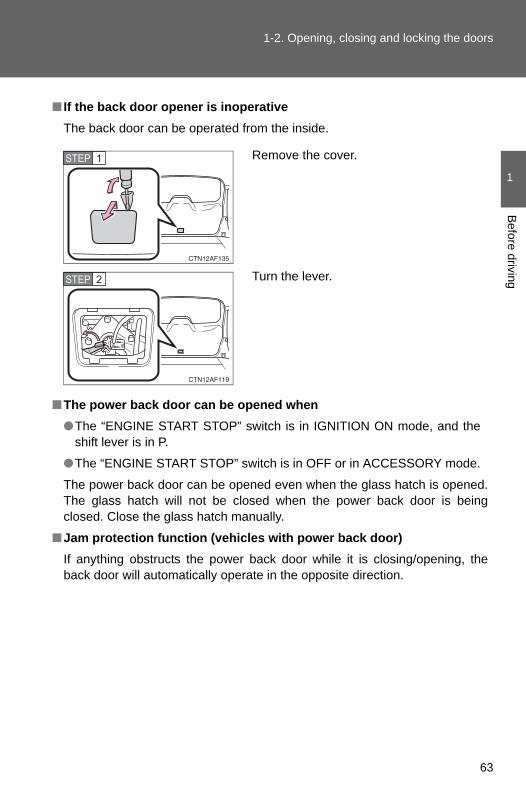
■ If the back door opener is inoperativeThe back door can be operated from the inside.
■The power back door can be opened when●The “ENGINE START STOP” switch is in IGNITION ON mode, and the
shift lever is in P.
●The “ENGINE START STOP” switch is in OFF or in ACCESSORY mode.
The power back door can be opened even when the glass hatch is opened.The glass hatch will not be closed when the power back door is beingclosed. Close the glass hatch manually.
■Jam protection function (vehicles with power back door)If anything obstructs the power back door while it is closing/opening, theback door will automatically operate in the opposite direction.
Remove the cover.
Turn the lever.
STEP 1
STEP 2
63

1-2. Opening, closing and locking the doors
■ If the power back door does not workThe back door must be initialized. To initialize, close the back door com-pletely by hand.
■Back door closer (vehicles with power back door)In the event that the back door is left slightly open, the back door closer willautomatically close it to the fully closed position.
■Fall-down protection function (vehicles with power back door)If excessive force is applied to the back door while it is opening automati-cally, the power back door will stop at that position, preventing itself from fall-ing down.
■Customization that can be configured at Toyota dealerSettings (e.g. wireless remote control) can be changed. (Customizable features →P. 602)
64
1-2. Opening, closing and locking the doors
1
Before driving
CAUTION
■Caution while driving●Keep the back door closed while driving.
If the back door is left open, it may hit near-by objects while driving or lug-gage may be unexpectedly thrown out, causing an accident.In addition, exhaust gases may enter the vehicle, causing death or a seri-ous health hazard. Make sure to close the back door before driving.
●Before driving the vehicle, make sure that the back door is fully closed. Ifthe back door is not fully closed, it may open unexpectedly while driving,causing an accident.
●Never let anyone sit in the luggage compartment. In the event of suddenbraking or a collision, they are susceptible to death or serious injury.
■When children are in the vehicleObserve the following precautions.Failure to do so may result in death or serious injury.
●Do not leave children alone in the luggage compartment.If a child is accidentally locked in the luggage compartment, they couldhave heat exhaustion.
●Do not allow a child to open or close the back door.Doing so may cause the back door to operate unexpectedly, or cause thechild’s hands, head, or neck to be caught by the closing back door.
65

1-2. Opening, closing and locking the doors
CAUTION
■Operating the back doorObserve the following precautions.Failure to do so may cause parts of the body to be caught, resulting in deathor serious injury.
●Remove any heavy loads, such as snow and ice, from the back doorbefore opening it. Failure to do so may cause the back door to fall closedagain after it is opened.
●When opening or closing the back door, thoroughly check to make surethe surrounding area is safe.
● If anyone is in the vicinity, make sure they are safe and let them know thatthe back door is about to open or close.
●Use caution when opening or closing the back door in windy weather as itmay move abruptly in strong wind.
●Do not pull on the back door damper stay to close the back door, and donot hang on the back door damper stay. Doing so may cause hands to be caught or the back door damper stay tobreak, causing an accident.
●The back door may fall if it is notopened fully. It is more difficult to openor close the back door on an inclinethan on a level surface, so beware ofthe back door unexpectedly opening orclosing by itself. Make sure that theback door is fully open and securebefore using the luggage compartment.
●When closing the back door, take extracare to prevent your fingers etc. frombeing caught.
●When closing the back door, make sureto press it lightly on its outer surface. Ifthe back door strap is used to fullyclose the back door, it may result inhands or arms being caught.
66

1-2. Opening, closing and locking the doors
1
Before driving
CAUTION
●Do not attach any accessories other than genuine Toyota parts to the backdoor. Such additional weight on the back door may cause the back door tofall closed again after it is opened.
■Back door closer (vehicles with power back door)
●Use caution when using the back door closer as it still operates when thepower back door system is canceled.
■Power back doorObserve the following precautions when operating the power back door.Failure to do so may cause death or serious injury.
●Check the safety of the surrounding area to make sure there are no obsta-cles or anything that could cause any of your belongings to get caught.
● If anyone is in the vicinity, make sure they are safe and let them know thatthe back door is about to open or close.
● If the power back door main switch is turned off while the back door isoperating during automatic operation, the back door stops operating. Takeextra care when on an incline, as the back door may open or close sud-denly.
● In the event that the back door is leftslightly open, the back door closer willautomatically close it to the fully closedposition. It takes several secondsbefore the back door closer begins tooperate. Be careful not to catch fingersor anything else in the back door, asthis may cause bone fractures or otherserious injuries.
67

1-2. Opening, closing and locking the doors
CAUTION
●On an incline, the back door may fall after it opens automatically. Makesure the back door is fully open and secure.
● In the following situations, the power back door may detect an abnormalityand automatic operation may be stopped. In this case, the back door hasto be operated manually. Take extra care in this situation, as the stoppedback door may suddenly fall, causing an accident.
• When the back door contacts an obstacle• Vehicles without smart key system: When the battery voltage suddenly
drops, such as when the engine switch is turned to the “ON” position orthe engine is started during automatic operation
• Vehicles with smart key system: When the battery voltage suddenlydrops, such as when the “ENGINE START STOP” switch is turned toIGNITION ON mode or the engine is started during automatic opera-tion
●Do not attach any accessories other than genuine Toyota parts to the backdoor. The power back door may not operate, causing itself to malfunction,or the back door may fall closed again after it is opened.
■Jam protection function (vehicles with power back door)Observe the following precautions. Failure to do so may cause death or serious injury.
●Never use any part of your body to intentionally activate the jam protectionfunction.
●The jam protection function may not work if something gets caught justbefore the back door fully closes. Be careful not to catch fingers or any-thing else.
●The jam protection function may not work depending on the shape of theobject that is caught. Be careful not to catch fingers or anything else.
68

1-2. Opening, closing and locking the doors
1
Before driving
NOTICE
■Back door damper staysThe back door is equipped with damper stays that hold the back door inplace.
Observe the following precautions.Failure to do so may cause damage to the back door damper stay, resultingin malfunction.
■To prevent back door closer malfunctionDo not apply excessive force to the back door while the back door closer isoperating.
■To prevent damage to the power back door●Make sure that there is no ice between the back door and frame that
would prevent movement of the back door. Operating the power back doorwhen excessive load is present on the back door may cause a malfunc-tion.
●Do not apply excessive force to the back door while the power back dooris operating.
●Take care not to damage the sensors (installed on the right and left edgesof the power back door) with a knife or other sharp object. If the sensor isdisconnected, the power back door will not operate in automatic operation.
●Do not attach any foreign objects, suchas stickers, plastic sheets, or adhesivesto the damper stay rod.
●Do not touch the damper stay rod withgloves or other fabric items.
●Do not attach any accessories otherthan genuine Toyota parts to the backdoor.
●Do not place your hand on the damperstay or apply lateral forces to it.
69

1-2. Opening, closing and locking the doors
Glass hatch∗
■Opening and closing the glass hatch●Make sure that the rear wiper is switched off.
●Do not rotate the rear wiper arm while the glass hatch is opening. (If therear wiper arm is rotated, close the glass hatch as it is then switch on thewiper. The rear wiper arm will return to the correct position automaticallyafter wiping.)
●Make sure that the back door is closed before closing the glass hatch.
The glass hatch can be opened using the glass hatch opener or wire-less remote control.
■ Wireless remote control (vehicles without smart key sys-tem)→P. 48
■ Entry function (vehicles with smart key system)→P. 36
■ Glass hatch openerPress and hold the button topop up the glass hatch.Raise
The glass hatch can beopened only when the backdoor is closed.
∗: If equipped
70

1-2. Opening, closing and locking the doors
1
Before driving
CAUTION
■While driving●Keep the glass hatch closed while driving.
If the glass hatch is left open, it may hit near-by objects while driving orluggage may be unexpectedly thrown out, causing an accident.In addition, exhaust gases may enter the vehicle, causing death or a seri-ous health hazard. Make sure to close the glass hatch before driving.
●Before driving the vehicle, make sure that the glass hatch is fully closed. Ifthe glass hatch is not fully closed, it may open unexpectedly while driving,causing an accident.
■When children are in the vehicleDo not allow a child to open or close the glass hatch.Doing so may cause the glass hatch to operate unexpectedly, or cause thechild's hands, head, or neck to be caught by the closing glass hatch.
■Operating the glass hatchObserve the following precautions.Failure to do so may cause parts of the body to be caught, resulting in deathor serious injury.
●Remove any heavy loads, such as snow and ice, from the glass hatchbefore opening it. Failure to do so may cause the glass hatch fall closedagain after it is opened.
●When opening or closing the glass hatch, thoroughly check to make surethe surrounding area is safe.
● If anyone is in the vicinity, make sure they are safe and let them know thatthe glass hatch is about to open or close.
●Use caution when opening or closing the glass hatch in windy weather asit may move abruptly in strong wind.
71

1-2. Opening, closing and locking the doors
CAUTION
●Do not pull on the glass hatch damper stay to close the glass hatch, anddo not hang on the glass hatch damper stay.Doing so may cause hands to be caught or the glass hatch damper stay tobreak, causing an accident.
●Do not attach any accessories other than genuine Toyota parts to theglass hatch. Such additional weight on the glass hatch may cause theglass hatch to fall closed again after it is opened, resulting in death or seri-ous injury.
●Do not open the glass hatch while the rear wiper is switched on. (If the rearwiper is switched on while the glass hatch is opening, the wiper motordrive disc is swinging at the door panel.)
●The glass hatch may fall if it is notopened fully. It is more difficult to openor close the glass hatch on an inclinethan on a level surface, so beware ofthe glass hatch unexpectedly openingor closing by itself. Make sure that theglass hatch is fully open and securebefore using the luggage compart-ment. Also pay attention to your per-sonal belongings such as bags andties.
●When closing the glass hatch, takeextra care to prevent your fingers etc.from being caught. Also pay attention toyour personal belongings such as bagsand ties.
●When closing the glass hatch, makesure to press it lightly on its outer sur-face.
72

1-2. Opening, closing and locking the doors
1
Before driving
CAUTION
●Do not close the glass hatch while the rear wiper is switched on. The rearwiper arm may be restarted suddenly after closing the glass hatch.
NOTICE
■Glass hatch damper staysThe glass hatch is equipped with damper stays that hold the glass hatch inplace. Observe the following precautions.Failure to do so may cause damage to the glass hatch damper stay, result-ing in malfunction.
●Do not insert any object in the wipermotor drive disc.
●Do not attach any foreign objects, suchas strikers, plastic sheets, or adhesivesto the damper stay rod.
●Do not touch the damper stay rod withgloves or other fabric items.
●Do not attach any accessories otherthan genuine Toyota parts to the glasshatch.
●Do not place your hand or foot on thedamper stay or apply lateral forces to it.
73

1-3. Adjustable components (seats, mirrors, steering wheel)
Front seats
Manual seat
Seat position adjustment leverSeatback angle adjustment leverVertical height adjustment lever (driver’s side only)Seat cushion (front) angle adjustment knob (driver’s side only)Pull up the lever until the lock is completely released.
74

1-3. Adjustable components (seats, mirrors, steering wheel)
1
Before driving
Active head restraints
When the occupant’s lower backpresses against the seatbackduring a rear-end collision, thehead restraint moves slightly for-ward and upward to help reducethe risk of whiplash to the seatoccupant.
Power seat
Seat position adjustment switchSeatback angle adjustment switchSeat cushion (front) angle adjustment switch (driver’s side only)Vertical height adjustment switch (driver’s side only)Driver’s seat leg support adjustment switch (if equipped)Seat lumbar support adjustment switch (driver’s side only)
75

1-3. Adjustable components (seats, mirrors, steering wheel)
■Active head restraintsEven small forces applied to the seatback may cause the head restraint tomove. Pushing up a locked head restraint forcibly may cause the inner struc-ture of the head restraint to appear. This does not indicate a problem.
CAUTION
■Seat adjustment●Be careful that the seat does not hit passengers or luggage.
●Do not recline the seat more than necessary when the vehicle is in motionto reduce the risk of sliding under the lap belt. If the seat is too reclined, the lap belt may slide past the hips and applyrestraint forces directly to the abdomen or your neck may contact theshoulder belt, increasing the risk of death or serious injury in the event ofan accident.
●Manual seat only: After adjusting the seat, make sure that the seat islocked in position.
Inner structure
Duringrear-endcollision
76

1
Before driving
1-3. Adjustable components (seats, mirrors, steering wheel)
Rear seats
Moving a second seat for third seat access
■ Getting in the vehicle (right side only)Pull up the lever and fold downthe seatback. The seat will slideforward.
Move the seat to the front-mostposition.
■ Second seatsSeat position adjustmentleverSeatback angle adjustmentlever
Pull up the lever until the lockis completely released.
■ Third seatsThe third seats do not have a seat adjustment function.
77

1-3. Adjustable components (seats, mirrors, steering wheel)
■ Getting out of the vehicle (right side only)Lift the lever on the side of theseatback and fold down the seat-back. The seat will slide forward.
Move the seat to the front-mostposition.
■ After passengers have entered/exited the vehicleLift up the seatback and slide the seat backward until it locks.
Folding down the second seats
■ Before folding down the second seatsStow the rear center seat beltbuckle.
Pass the outer seat belts throughthe seat belt hangers and securethe seat belt plates.
This prevents the shoulder beltfrom being damaged.
Make sure that the seat belts areremoved from the hangers beforeusing them.
STEP 1
STEP 2
78

1-3. Adjustable components (seats, mirrors, steering wheel)
1
Before driving
■ Folding down the second seatsFrom inside
Pull the lever to unlock the seat-back and then fold the seatbackdown.
From outside (if equipped)
Pull the lever.
L: Left side and center secondseats
R:Right side second seat
■ After folding down the second seatsSlide the folded second seats tothe rear-most position.
79

1-3. Adjustable components (seats, mirrors, steering wheel)
Folding down the third seats
■ Before folding down the third seatsStow the third seat belt buckles.
Pass the seat belts through theseat belt hangers.
This helps to prevent the shoulderbelts from being damaged.
Make sure that the seat belts areremoved from the hangers beforeusing them.
■ Folding down the third seats While pulling the straps, folddown the seatbacks.
The head restraints will fold downautomatically when the straps arepulled.
STEP 1
STEP 2
80
1-3. Adjustable components (seats, mirrors, steering wheel)
1
Before driving
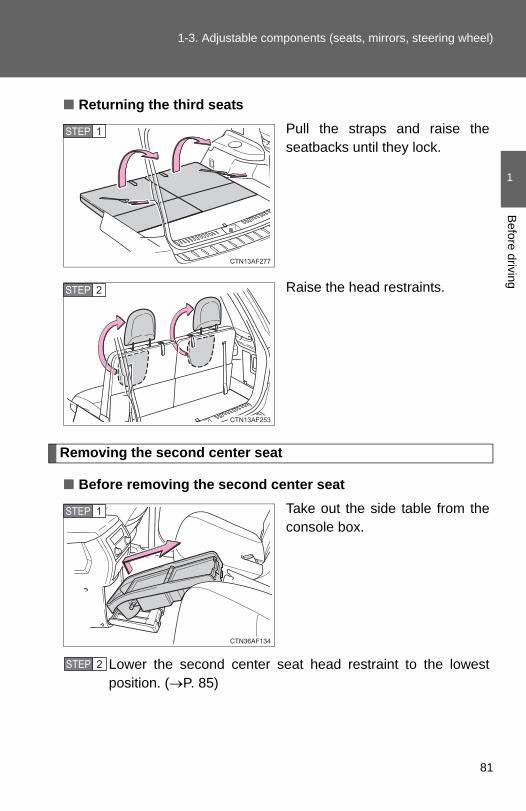
■ Returning the third seatsPull the straps and raise theseatbacks until they lock.
Raise the head restraints.
Removing the second center seat
■ Before removing the second center seatTake out the side table from theconsole box.
Lower the second center seat head restraint to the lowestposition. (→P. 85)
STEP 1
STEP 2
STEP 1
STEP 2
81

1-3. Adjustable components (seats, mirrors, steering wheel)
■ Removing the second center seatFold down the second centerseatback while pulling the seat-back lock release strap.
Pull the lock release lever toremove the second center seat.
Stow the second center seat inthe console box.
Make sure that the seat is securely locked in position andclose the console box door.
STEP 1
STEP 2
STEP 3
STEP 4
82

1-3. Adjustable components (seats, mirrors, steering wheel)
1
Before driving
Installing the second center seat
■ Before installing the second center seatTake out the second center seatfrom the console box.
Remove the side table, if used, from the second seat. (→P. 410)
■ Installing the second center seatFully engage the front pinswith the hooks, and swing thesecond center seat downward.Push down on the secondcenter seat to engage the rearpin locks.
Unfold the seatback and lock it.
Stow the side table in the consolebox.
STEP 1
STEP 2
STEP 1
STEP 2
83

1-3. Adjustable components (seats, mirrors, steering wheel)
CAUTION
■When adjusting a rear seat or removing the second center seat●Be careful that the seat does not hit passengers or luggage.
●Do not recline the seat more than necessary when the vehicle is in motionto reduce the risk of sliding under the lap belt. If the seat is too reclined,the lap belt may slide past the hips and apply restraint forces directly to theabdomen or your neck may contact the shoulder belt, increasing the risk ofdeath or serious injury in the event of an accident.
●Be careful not to get your hands or feet caught in the seat.
■Before folding down the rear seatsDo not fold down a rear seat when there are passengers sitting in the rearseats or when there is luggage placed on the rear seats.
■After adjusting the seatsObserve the following precautions. Failure to do so may result in death orserious injury.
●Make sure that the seat and seatback are securely locked in position bylightly rocking them back and forth.
●Second center seat: Make sure the seat is locked in place by trying toshake the seatback and lift up the rear part of the seat cushion.
●Check that the seat belts are not twisted or caught under the seat.
■Caution while drivingKeep the console box closed.Injuries may result in the event of an accident or sudden braking.
NOTICE
■When folding down the second seatsDo not fold the seatback forward with the luggage cover hooks attached.
■Removed second center seatAvoid putting heavy loads on the seat. The metallic seat pins may be dam-aged, and you may be unable to correctly reinstall the seat.
84

1
Before driving
1-3. Adjustable components (seats, mirrors, steering wheel)
Head restraints
Head restraints are provided for all seats.
Front seats
Vertical adjustment
Up
Pull the head restraints up.
Down
Push the head restraint downwhile pushing the lock releasebutton.
Angle adjustment (if equipped)
Second seats
Up
Pull the head restraints up.
Down
Push the head restraint downwhile pushing the lock releasebutton.
When using the center seat,raise the head restraint fromthe stowed position.
Lock release button
Lock release buttons
85

1-3. Adjustable components (seats, mirrors, steering wheel)
■Adjusting the height of the head restraints (except second center seatand third seats)
■Adjusting the rear center seat head restraintAlways raise the head restraint one level from the stowed position whenusing.
■Removing the front and second seat outer head restraints
■ When using the third seat head restraintsTo useTo fold
Make sure that the head restraints areadjusted so that the center of the headrestraint is closest to the top of your ears.
Pull the head restraint up while pushingthe lock release button.
86

1-3. Adjustable components (seats, mirrors, steering wheel)
1
Before driving
■ Installing the front and second seat outer head restraints
CAUTION
■Head restraint precautionsObserve the following precautions regarding the head restraints. Failure todo so may result in death or serious injury.
●Use the head restraints designed for each respective seat.
●Adjust the head restraints to the correct position at all times.
●After adjusting the head restraints, push down on them and make surethey are locked in position.
●Do not drive with the head restraints removed.
Align the head restraint with the installa-tion holes and push it down to the lockposition.
Press and hold the lock release buttonwhen lowering the head restraint.
87

1-3. Adjustable components (seats, mirrors, steering wheel)
Seat belts
Make sure that all occupants are wearing their seat belts before driv-ing the vehicle.
■ Correct use of the seat belts
● Extend the shoulder belt sothat it comes fully over theshoulder, but does notcome into contact with theneck or slide off the shoul-der.
● Position the lap belt as lowas possible over the hips.
● Adjust the position of theseatback. Sit up straightand well back in the seat.
● Do not twist the seat belt.
■ Fastening and releasing the seat beltFastening the belt
Push the tab into the buckleuntil a clicking sound is heard.
Releasing the belt
Press the release button.
Release button
88

1-3. Adjustable components (seats, mirrors, steering wheel)
1
Before driving
Seat belt pretensioners (front seats)
The pretensioner helps the seatbelt to quickly restrain the occu-pant by retracting the seat beltwhen the vehicle is subjected tocertain types of severe frontalcollision or a vehicle rollover.
The pretensioner may not acti-vate in the event of a minor frontalimpact, a side impact or a rearimpact.
■ Adjusting the height of the belt (front seats)DownUp
Move the height adjuster upand down as needed until youhear a click.
■Emergency locking retractor (ELR)The retractor will lock the belt during a sudden stop or on impact. It may alsolock if you lean forward too quickly. A slow, easy motion will allow the belt toextend so that you can move around fully.
■Automatic locking retractor (ALR)When a passenger's shoulder belt is completely extended and thenretracted even slightly, the belt is locked in that position and cannot beextended. This feature is used to hold the child restraint system (CRS) firmly.To free the belt again, fully retract the belt and then pull the belt out oncemore. (→P. 147)
89

1-3. Adjustable components (seats, mirrors, steering wheel)
■Pregnant women
■People suffering illnessObtain medical advice and wear the seat belt in the proper way.
■When not using the rear seat beltsSecond seat belts
Third seat belts
Obtain medical advice and wear the seatbelt in the proper way. (→P. 88)
Women who are pregnant should positionthe lap belt as low as possible over thehips in the same manner as other occu-pants. Extend the shoulder belt com-pletely over the shoulder and position thebelt across the chest. Avoid belt contactover the rounding of the abdominal area.
If the seat belt is not worn properly, notonly a pregnant woman, but also the fetuscould suffer death or serious injury as aresult of sudden braking or a collision.
Pass the outer seat belts through the seatbelt hangers and secure the seat beltplates to prevent the shoulder belts frombeing damaged.
Pass the outer seat belts through the seatbelt hangers to help prevent the shoulderbelts from being damaged.
90

1-3. Adjustable components (seats, mirrors, steering wheel)
1
Before driving
■Child seat belt usageThe seat belts of your vehicle were principally designed for persons of adultsize.
●Use a child restraint system appropriate for the child, until the childbecomes large enough to properly wear the vehicle's seat belt. (→P. 142)
●When the child becomes large enough to properly wear the vehicle's seatbelt, follow the instructions on P. 88 regarding seat belt usage.
■Replacing the belt after the pretensioner has been activatedIf the vehicle is involved in multiple collisions, the pretensioner will activatefor the first collision, but will not activate for the second or subsequent colli-sions.
■Seat belt extender
CAUTION
Observe the following precautions to reduce the risk of injury in the event ofsudden braking, sudden swerving or an accident.Failure to do so may cause death or serious injury.
■Wearing a seat belt●Ensure that all passengers wear a seat belt.
●Always wear a seat belt properly.
●Each seat belt should be used by one person only. Do not use a seat beltfor more than one person at once, including children.
●Toyota recommends that children be seated in the rear seat and alwaysuse a seat belt and/or an appropriate child restraint system.
If your seat belts cannot be fastenedsecurely because they are not longenough, a personalized seat beltextender is available from your Toyotadealer free of charge.
91

1-3. Adjustable components (seats, mirrors, steering wheel)
CAUTION
●Do not recline the seat any more than necessary to achieve a proper seat-ing position. The seat belt is most effective when the occupants are sittingup straight and well back in the seats.
●Do not wear the shoulder belt under your arm.
●Always wear your seat belt low and snug across your hips.
■When children are in the vehicleDo not allow children to play with the seat belt. If the seat belt becomestwisted around a child’s neck, it may lead to choking or other serious injuriesthat could result in death. If this occurs and the buckle cannot be unfas-tened, scissors should be used to cut the belt.
■Adjustable shoulder anchorAlways make sure the shoulder belt is positioned across the center of yourshoulder. The belt should be kept away from your neck, but not falling offyour shoulder. Failure to do so could reduce the amount of protection in anaccident and cause death or serious injuries in the event of a sudden stop,sudden swerve or accident. (→P. 89)
■Seat belt pretensioners●Do not place anything, such as a cushion, on the front passenger's seat.
Doing so will disperse the passenger's weight, which prevents the sensorfrom detecting the passenger's weight properly. As a result, the seat beltpretensioner for the front passenger's seat may not activate in the event ofa collision.
● If the pretensioner has activated, the SRS warning light will come on. Inthat case, the seat belt cannot be used again and must be replaced atyour Toyota dealer.
92

1-3. Adjustable components (seats, mirrors, steering wheel)
1
Before driving
CAUTION
■Seat belt damage and wear●Do not damage the seat belts by allowing the belt, plate, or buckle to be
jammed in the door.
● Inspect the seat belt system periodically. Check for cuts, fraying, and looseparts. Do not use a damaged seat belt until it is replaced. Damaged seatbelts cannot protect an occupant from death or serious injury.
●Ensure that the belt and tab are locked and the belt is not twisted.If the seat belt does not function correctly, immediately contact your Toyotadealer.
●Replace the seat assembly, including the belts, if your vehicle has beeninvolved in a serious accident, even if there is no obvious damage.
●Do not attempt to install, remove, modify, disassemble or dispose of theseat belts. Have any necessary repairs carried out by your Toyota dealer.Inappropriate handling of the pretensioner may prevent it from operatingproperly resulting in death or serious injury.
■Using a seat belt extender●Do not wear the seat belt extender if you can fasten the seat belt without
the extender.
●Do not use the seat belt extender when installing a child restraint systembecause the belt will not securely hold the child restraint system, increas-ing the risk of death or serious injury in the event of an accident.
●The personalized extender may not be safe on another vehicle, whenused by another person, or at a different seating position other than theone originally intended.
NOTICE
■When using a seat belt extenderWhen releasing the seat belt, press on the buckle release button on theextender, not on the seat belt.This helps prevent damage to the vehicle interior and the extender itself.
93

1-3. Adjustable components (seats, mirrors, steering wheel)
Steering wheel
CAUTION
■Caution while drivingDo not adjust the steering wheel while driving.Doing so may cause the driver to mishandle the vehicle and an accident,resulting in death or serious injury.
■After adjusting the steering wheelMake sure that the steering wheel is securely locked. Otherwise, the steering wheel may move suddenly, possibly causing anaccident and resulting in death or serious injury.
The steering wheel can be adjusted to a comfortable position.
Hold the steering wheel andpress the lever down.
Adjust to the ideal position bymoving the steering wheelhorizontally and vertically.
After adjustment, pull the leverup to secure the steeringwheel.
STEP 1
STEP 2
94

1
Before driving
1-3. Adjustable components (seats, mirrors, steering wheel)
Anti-glare inside rear view mirror
Glare from the headlights of vehicles behind can be reduced byusing the following functions.
■ Manual anti-glare inside rear view mirrorNormal positionAnti-glare position
■ Auto anti-glare inside rear view mirrorIn automatic mode, sensors are used to detect the headlights ofvehicles behind and the reflected light is automatically reduced.
Type A
Turns automatic mode on/off
The indicator comes on whenautomatic mode is turned on.
Vehicles without smart keysystem:The mirror will revert to auto-matic mode each time theengine switch is turned to the“ON” position.
Vehicles with smart key sys-tem:The mirror will revert to auto-matic mode each time the“ENGINE START STOP”switch is turned to IGNITIONON mode.
95

1-3. Adjustable components (seats, mirrors, steering wheel)
Adjusting the height of the rear view mirror
Adjust the height of the rear viewmirror by moving it up and down.
Type B
Turns automatic mode on/off
The indicator comes on whenautomatic mode is turned on.
Vehicles without smart keysystem:The mirror will revert to auto-matic mode each time theengine switch is turned to the“ON” position.
Vehicles with smart key sys-tem:The mirror will revert to auto-matic mode each time the“ENGINE START STOP”switch is turned to IGNITIONON mode.
96

1-3. Adjustable components (seats, mirrors, steering wheel)
1
Before driving
■To prevent sensor error (vehicles with auto anti-glare inside rear viewmirror)
CAUTION
■Caution while drivingDo not adjust the position of the mirror while driving.Doing so may lead to mishandling of the vehicle and an accident, resulting indeath or serious injury.
To ensure that the sensors operate prop-erly, do not touch or cover them.
97

1-3. Adjustable components (seats, mirrors, steering wheel)
Outside rear view mirrors
Mirror angle can be adjusted using the switches.
Select a mirror to adjust.
LeftRight
Adjust the mirror.
UpRightDownLeft
STEP 1
STEP 2
98

1-3. Adjustable components (seats, mirrors, steering wheel)
1
Before driving
Folding back the mirrors
Push backward to fold the mir-rors.
■The outside rear view mirrors can be operated whenVehicles without smart key system
The engine switch is in the “ACC” or “ON” position.
Vehicles with smart key system
The “ENGINE START STOP” switch is in ACCESSORY or IGNITION ONmode.
■When the mirrors are fogged up (vehicles with outside rear view mirrordefoggers)Turn on the mirror defoggers to defog the mirrors. (→P. 289)
99
1-3. Adjustable components (seats, mirrors, steering wheel)
CAUTION
■When driving the vehicleObserve the following precautions while driving.Failing to do so may result in loss of control of the vehicle and cause an acci-dent, resulting in death or serious injury.
●Do not adjust the mirrors while driving.
●Do not drive with the mirrors folded back.
●Both the driver and passenger side mirrors must be extended and properlyadjusted before driving.
■When the mirror defoggers are operating (vehicles with outside rearview mirror defoggers)Do not touch the rear view mirror surfaces, as they can become very hot andburn you.
100

1-4. Opening and closing the windows and moon roof
1
Before driving
Power windows
Lock switch
Press the switch down to lockthe passenger window switches.
Use this switch to prevent chil-dren from accidentally opening orclosing a passenger window.
The power windows can be opened and closed using the followingswitches.
ClosingOne-touch closing (driver’swindow only)*OpeningOne-touch opening (driver’swindow only)*
*: Pressing the switch in theopposite direction will stop win-dow travel partway.
■The power windows can be operated whenVehicles without smart key system
The engine switch is in the “ON” position.
Vehicles with smart key systemThe “ENGINE START STOP” switch is in IGNITION ON mode.
101

1-4. Opening and closing the windows and moon roof
■Operating the power windows after turning the engine offVehicles without smart key system
The power windows can be operated for approximately 45 seconds after theengine switch is turned to the “ACC” or “LOCK” position. They cannot, how-ever, be operated once either front door is opened.
Vehicles with smart key systemThe power windows can be operated for approximately 45 seconds after the“ENGINE START STOP” switch is turned to ACCESSORY mode or turnedOFF. They cannot, however, be operated once either front door is opened.
■Jam protection function (driver’s window only)If an object becomes caught between the window and the window frame,window travel is stopped and the window is opened slightly.
■When the power window does not close normallyIf the jam protection function is operating abnormally and a window cannotbe closed, perform the following operations using the power window switchon the driver’s door.
●Vehicles without a smart key system: After stopping the vehicle, the win-dow can be closed by holding the power window switch in the one-touchclosing position while the engine switch is turned to the “ON” position.
●Vehicles with a smart key system: After stopping the vehicle, the windowcan be closed by holding the power window switch in the one-touch clos-ing position while the “ENGINE START STOP” switch is turned to IGNI-TION ON mode.
● If the window still cannot be closed even by carrying out the operationexplained above, initialize the function by performing the following proce-dure.
Hold the power window switch in the one-touch closing position.Continue holding the switch for a further 6 seconds after the win-dow has closed.
Hold the power window switch in the one-touch opening position.Continue holding the switch for a further 2 seconds after the win-dow has opened completely.
Hold the power window switch in the one-touch closing positiononce again. Continue holding the switch for a further 2 secondsafter the window has closed.
STEP 1
STEP 2
STEP 3
102

1-4. Opening and closing the windows and moon roof
1
Before driving
If you release the switch while the window is moving, start again from thebeginning.If the window continues to close but then re-open slightly even after perform-ing the above procedure correctly, have the vehicle inspected by your Toyotadealer.
CAUTION
■Closing the windowsObserve the following precautions. Failing to do so may result in death or serious injury.
●Check to make sure that all passengers do not have any part of their bodyin a position where it could be caught when a window is being operated.
●Do not allow children to operate the power windows. Closing a power window on someone can cause serious injury, and insome instances, even death.
■Jam protection function (driver’s window only)●Never try jamming any part of your body to activate the jam protection
function intentionally.
●The jam protection function may not work if something gets caught justbefore the window fully closes.
●The jam protection function may not work depending on the shape of theobject that is caught. Be careful not to catch fingers or anything else.
103

1-4. Opening and closing the windows and moon roof
Moon roof∗
Use the overhead switches to open, close, and tilt the moon roof upand down.
■ Opening and closingOpen
The moon roof stops slightlybefore the fully opened posi-tion.Move the switch backwardagain to fully open.
Close
Move the switch forward tostop the moon roof partway.
■ Tilting up and downTilt upTilt down
Push the switch in either direc-tion to stop the moon roof part-way.
∗: If equipped
104

1-4. Opening and closing the windows and moon roof
1
Before driving
■The moon roof can be operated whenVehicles without smart key system
The engine switch is in the “ON” position.
Vehicles with smart key systemThe “ENGINE START STOP” switch is in IGNITION ON mode.
■Operating the moon roof after turning the engine offVehicles without smart key system
The moon roof can be operated for approximately 45 seconds after theengine switch is turned to the “ACC” or “LOCK” position. It cannot, however,be operated once either front door is opened.
Vehicles with smart key systemThe moon roof can be operated for approximately 45 seconds after the“ENGINE START STOP” switch is turned to ACCESSORY mode or turnedOFF. They cannot, however, be operated once either front door is opened.
■Jam protection functionIf an object is detected between the moon roof and the frame while closingor tilting down, travel is stopped and the moon roof opens slightly.
■To reduce wind noiseDrive with the moon roof opened to slightly before the fully open position asdriving with the moon roof opened fully will cause wind noise.
105

1-4. Opening and closing the windows and moon roof
■When the moon roof does not close normallyPerform the following procedure:
● If the moon roof closes but then re-opens slightly
Stop the vehicle.
Press and hold the “SLIDE (open/close)” switch in the close posi-tion.*1
The moon roof will close, reopen and pause for approximately 10seconds.*2 Then it will close again, tilt up and pause for approxi-mately 1 second. Finally, it will tilt down, open and close.
Check to make sure that the moon roof is completely closed andthen release the switch.
● If the moon roof tilts down but then tilts back up
Stop the vehicle.
Press and hold the “UP” switch*1 until the moon roof moves into thetilt up position and stops.
Release the “UP” switch once and then press and hold the “UP”switch again.*1
The moon roof will pause for approximately 10 seconds in the tilt upposition.*2 Then it will adjust slightly and pause for approximately 1second. Finally, it will tilt down, open and close.
Check to make sure that the moon roof is completely closed andthen release the switch.
*1: If the switch is released at the incorrect time, the procedure willhave to be performed again from the beginning.
*2: If the switch is released after the above mentioned 10 secondpause, automatic operation will be disabled. In that case, pressand hold the “SLIDE (open/close)” switch in the close position orthe “UP” switch, and the moon roof will tilt up and pause forapproximately 1 second. Then it will tilt down, open and close.Check to make sure that the moon roof is completely closed andthen release the switch.
If the moon roof does not fully close even after performing the above proce-dure correctly, have the vehicle inspected by your Toyota dealer.
STEP 1
STEP 2
STEP 3
STEP 1
STEP 2
STEP 3
STEP 4
106
1-4. Opening and closing the windows and moon roof
1
Before driving
■SunshadeThe sunshade can be opened and closed manually. However, the sunshadewill open automatically when the moon roof is opened.
■Moon roof open reminder function (vehicles with multi-information dis-play)
Vehicles without smart key systemAn alarm will sound when the driver’s door is opened with the moon roof notfully closed and the engine switch OFF.
Vehicles with smart key systemAn alarm will sound when the driver’s door is opened with the moon roof notfully closed and the “ENGINE START STOP” switch OFF.
CAUTION
■Opening the moon roofObserve the following precautions.Failure to do so may cause death or serious injury.
●Do not allow any passengers to put their hands or heads outside the vehi-cle while it is moving.
●Do not sit on top of the moon roof.
■Closing the moon roofObserve the following precautions. Failing to do so may result in death or serious injury.
●Check to make sure that all passengers do not have any part of their bod-ies in a position where it could be caught when the moon roof is beingoperated.
●Do not allow children to operate the moon roof. Closing the moon roof on someone can cause death or serious injury.
107

1-4. Opening and closing the windows and moon roof
CAUTION
■Jam protection function●Never try jamming any part of your body to activate the jam protection
function intentionally.
●The jam protection function may not work if something gets caught justbefore the moon roof fully closes.
●The jam protection function may not work depending on the shape of theobject that is caught. Be careful not to catch fingers or anything else.
108

1-5. Refueling
1
Before driving
Opening the fuel tank cap
Perform the following steps to open the fuel tank cap.
■ Before refueling the vehicleVehicles without smart key system
Turn the engine switch OFF and ensure that all the doors andwindows are closed.
Vehicles with smart key systemTurn the “ENGINE START STOP” switch OFF and ensure thatall the doors and windows are closed.
■ Opening the fuel tank capOpen the fuel filler door.
Turn the fuel tank cap slowlyto open.
STEP 1
STEP 2
109

1-5. Refueling
Closing the fuel tank cap
When replacing the fuel tankcap, turn it until a clicking soundis heard.
Once the cap is released, it willturn slightly in the opposite direc-tion.
Hang the fuel tank cap on theback of the fuel filler door.
STEP 3
■Fuel typesUse unleaded gasoline. (Octane rating 87 [Research Octane Number 91] orhigher)
■Fuel tank capacityApproximately 19.2 gal. (72.5 L, 15.9 Imp. gal.)
110

1-5. Refueling
1
Before driving
CAUTION
■Refueling the vehicleObserve the following precautions while refueling the vehicle. Failure to do so may result in death or serious injury.
●Touch the vehicle or some other metal surface to discharge any staticelectricity.Sparks resulting from discharging static electricity may cause the fuelvapors to ignite.
●Always hold the grips on the fuel tank cap and turn it slowly to remove it. A whooshing sound may be heard when the fuel tank cap is loosened.Wait until the sound cannot be heard before fully removing the cap.In hot weather, pressurized fuel may spray out of the filler neck and causeinjury.
●Do not allow anyone that has not discharged static electricity from theirbodies to come close to an open fuel tank.
●Do not inhale vaporized fuel.Fuel contains substances that are harmful if inhaled.
●Do not smoke while refueling the vehicle.Doing so may cause the fuel to ignite and cause a fire.
●Do not return to the vehicle or touch any person or object that is staticallycharged.This may cause static electricity to build up, resulting in a possible ignitionhazard.
■When replacing the fuel capDo not use anything but a genuine Toyota fuel tank cap designed for yourvehicle. Doing so may cause a fire or other incident which may result indeath or serious injury.
111

1-5. Refueling
NOTICE
■RefuelingDo not spill fuel during refueling.Doing so may damage the vehicle, such as causing the exhaust systems tooperate abnormally or damaging fuel system components or the vehicle'spainted surface.
112

1-6. Theft deterrent system∗
1
Before driving
Engine immobilizer system
The vehicle's keys have built-in transponder chips that prevent theengine from starting if the key has not been previously registered inthe vehicle's on-board computer.Never leave the keys inside the vehicle when you leave the vehicle.
Vehicles without navigation system
Vehicles without smart keysystem: The indicator lightflashes after the key has beenremoved from the engineswitch to indicate that the sys-tem is operating.
The indicator light stops flash-ing after the registered keyhas been inserted into theengine switch to indicate thatthe system has been can-celed.
Vehicles with smart key sys-tem: The indicator light flashesafter the “ENGINE STARTSTOP” switch has been turnedOFF to indicate that the sys-tem is operating.
The indicator light stops flash-ing after the “ENGINE STARTSTOP” switch has been turnedto ACCESSORY or IGNITIONON mode to indicate that thesystem has been canceled.
∗: If equipped
113

1-6. Theft deterrent system
Vehicles with navigation system
Vehicles without smart keysystem: The indicator lightflashes after the key has beenremoved from the engineswitch to indicate that the sys-tem is operating.
The indicator light stops flash-ing after the registered keyhas been inserted into theengine switch to indicate thatthe system has been can-celed.
Vehicles with smart key sys-tem: The indicator light flashesafter the “ENGINE STARTSTOP” switch has been turnedOFF to indicate that the sys-tem is operating.
The indicator light stops flash-ing after the “ENGINE STARTSTOP” switch has been turnedto ACCESSORY or IGNITIONON mode to indicate that thesystem has been canceled.
114

1-6. Theft deterrent system
1
Before driving
■System maintenanceThe vehicle has a maintenance-free type engine immobilizer system.
■Conditions that may cause the system to malfunction● If the key is in contact with a metallic object
● If the key is in close proximity to or touching a key with the security sys-tem (key with a built-in transponder chip) of another vehicle
■Certifications for the engine immobilizer system ●For vehicles sold in the U.S.A.
Vehicles without smart key system
FCC ID: MOZRI-21BTY
Vehicles with smart key system
FCC ID: NI4TMIMB-1
This device complies with Part 15 of the FCC Rules. Operation is subject tothe following two conditions: (1) this device may not cause harmful interfer-ence, and (2) this device must accept any interference received, includinginterference that may cause undesired operation.
FCC WARNING:Changes or modifications not expressly approved by the party responsiblefor compliance could void the user's authority to operate the equipment.
●For vehicles sold in Canada
Operation is subject to the following two conditions: (1) this device may notcause interference, and (2) this device must accept any interference, includ-ing interference that may cause undesired operation of the device.
NOTICE
■To ensure the system operates correctlyDo not modify or remove the system. If modified or removed, the proper operation of the system cannot be guar-anteed.
115

1-6. Theft deterrent system
Alarm∗
∗: If equipped
The system sounds the alarm and flashes the lights when forcibleentry is detected.
■ Triggering of the alarmThe alarm is triggered in the following situations when the alarmis set.
● A locked door is unlocked or opened in any way other thanusing the entry function (vehicles with smart key system) orwireless remote control or mechanical key. (The doors willlock again automatically.)
● The hood is opened.
● The locked glass hatch is opened in any way other than usingthe wireless remote control door lock function or entry function(vehicles with smart key system).
● The battery is reconnected.
■ Setting the alarm systemVehicles without navigation system
Close the doors, glass hatchand hood, and lock all thedoors. The system will be setautomatically after 30 sec-onds.
The indicator light changesfrom being on to flashing whenthe system is set.
116

1-6. Theft deterrent system
1
Before driving
■System maintenanceThe vehicle has a maintenance-free type alarm system.
■ Items to check before locking the vehicleTo prevent unexpected triggering of the alarm and vehicle theft, make sureof the following.
●Nobody is in the vehicle.
●The windows and moon roof are closed before the alarm is set.
●No valuables or other personal items are left in the vehicle.
Vehicles with navigation system
Close the doors, glass hatchand hood, and lock all thedoors. The system will be setautomatically after 30 sec-onds.
The indicator light changesfrom being on to flashing whenthe system is set.
■ Deactivating or stopping the alarm● Unlock the doors.
● Vehicles without smart key system: Turn the engine switch tothe “ON” position, or start the engine. (The alarm will be deac-tivated or stopped after a few seconds.)
● Vehicles with smart key system: Turn the “ENGINE STARTSTOP” switch to IGNITION ON mode, or start the engine.(The alarm will be deactivated or stopped after a few sec-onds.)
● Open the glass hatch using the entry function (vehicles withsmart key system) or wireless remote control (vehicles with-out smart key system).
117

1-6. Theft deterrent system
■Triggering of the alarmThe alarm may be triggered in the following situations. (Stopping the alarmdeactivates the alarm system.)
■Panic mode→P. 50
■When the battery is disconnectedBe sure to cancel the alarm system.If the battery is disconnected before canceling the alarm, the system may betriggered when the battery is reconnected.
■Alarm-operated door lock●When the alarm is operating, the doors are locked automatically to pre-
vent intruders.
●Do not leave the key inside the vehicle when the alarm is operating, andmake sure the key is not inside the vehicle when recharging or replacingthe battery.
■When using the key to unlock the doorsDeactivate the alarm.
●A person inside the vehicle opens adoor or the hood when the vehicle islocked.
●The battery is recharged or replacedwhen the vehicle is locked.
118

1-6. Theft deterrent system
1
Before driving
NOTICE
■To ensure the system operates correctlyDo not modify or remove the system. If modified or removed, the proper operation of the system cannot be guar-anteed.
119

1-6. Theft deterrent system
Theft prevention labels (U.S.A.)
These labels are attached tothe vehicle to reduce vehicletheft by facilitating the tracingand recovery of parts from sto-len vehicles. Do not removeunder penalty of law.
120

1-7. Safety information
1
Before driving
Correct driving posture
Drive in a good posture as follows:
Sit upright and well back inthe seat. (→P. 74)Adjust the position of theseat forward or backward toensure the pedals can bereached and easilydepressed to the extentrequired. (→P. 74)Adjust the seatback so thatthe controls are easily oper-able.Adjust the tilt and telescopicpositions of the steeringwheel downward so the air-bag is facing your chest. (→P. 94)Lock the head restraint inplace with the center of thehead restraint closest to thetop of your ears. (→P. 85)Wear the seat belt correctly.(→P. 88)
121

1-7. Safety information
CAUTION
■While driving●Do not adjust the position of the driver's seat while driving.
Doing so could cause the driver to lose control of the vehicle.
●Do not place a cushion between the driver or passenger and the seatback.A cushion may prevent correct posture from being achieved, and reducethe effectiveness of the seat belt and head restraint, increasing the risk ofdeath or serious injury to the driver or passenger.
●Do not place anything under the front seats.Objects placed under the front seats may become jammed in the seattracks and stop the seat from locking in place. This may lead to an acci-dent. The adjustment mechanism may also be damaged.
■Adjusting the seat position●Take care when adjusting the seat position to ensure that other passen-
gers are not injured by the moving seat.
●Do not put your hands under the seat or near the moving parts to avoidinjury.Fingers or hands may become jammed in the seat mechanism.
122

1
Before driving
1-7. Safety information
SRS airbags
The SRS airbags inflate when the vehicle is subjected to certaintypes of severe impacts that may cause significant injury to theoccupants. They work together with the seat belts to help reduce therisk of death or serious injury.
Front airbagsDriver airbag/front passenger airbagCan help protect the head and chest of the driver and front pas-senger from impact with interior components.Driver knee airbagCan help provide driver protection.
Side and curtain shield airbagsSide airbagsCan help protect the torso of the front seat occupants.Curtain shield airbagsCan help protect primarily the head of occupants in the outerseats.
123

1-7. Safety information
Airbag system components
Your vehicle is equipped with ADVANCED AIRBAGS designed basedon US motor vehicle safety standards (FMVSS208). The airbag sys-tem controls airbag deployment power for the driver and front pas-senger. The driver airbag system consists of the driver seat's positionsensor etc. The front passenger's airbag system consists of the frontpassenger occupant classification sensor etc.
Curtain shield airbagsSide airbagsFront passenger airbagSide and curtain shield air-bag sensorsDoor sensorsFront airbag sensorsFront passenger’s seat beltbuckle switchCurtain shield airbag sen-sors“AIR BAG ON” and “AIRBAG OFF” indicator lights
SRS warning lightDriver airbagDriver’s seat position sen-sorDriver’s seat belt buckleswitchDriver knee airbagAirbag sensor assemblyFront passenger occupantclassification system (ECUand sensors)
124

1-7. Safety information
1
Before driving
The main SRS airbag system components are shown above. TheSRS airbag system is controlled by the airbag sensor assembly. Theairbag sensor assembly consists of a safing sensor and an airbagsensor.
In certain types of severe frontal or side impacts or vehicle rollover,the SRS airbag system triggers the airbag inflators. A chemical reac-tion in the inflators quickly fills the airbags with non-toxic gas to helprestrain the motion of the occupants.
■SRS warning lightThis warning light system monitors the airbag sensor assembly, front airbagsensors, side and curtain shield airbag sensor assemblies, curtain shield air-bag sensor assemblies, door sensors, driver's seat position sensor, driver'sseat belt buckle switch, front passenger occupant classification system(ECU and sensors), “AIR BAG ON” and “AIR BAG OFF” indicator lights,front passenger’s seat belt buckle switch, front seat belt pretensionerassemblies, inflators, interconnecting wiring and power sources. (→P. 529)
■ If the SRS airbags deploy (inflate)●Bruising and slight abrasions may result from contact with a deploying
(inflating) SRS airbag.
●A loud noise and white powder will be emitted.
●Parts of the airbag module (steering wheel hub, airbag cover and inflator)as well as the front seats, and parts of the front and rear pillars and roofside rail, may be hot for several minutes. The airbag itself may also behot.
●The windshield may crack.
125

1-7. Safety information
■SRS airbag deployment conditions (front airbags)●The SRS front airbags will deploy in the event of an impact that exceeds
the set threshold level (the level of force corresponding to an approxi-mately 12 - 18 mph [20 - 30 km/h] frontal collision with a fixed wall thatdoes not move or deform).
However, this threshold velocity will be considerably higher if the vehiclestrikes an object, such as a parked vehicle or sign pole, which can move ordeform on impact, or if the vehicle is involved in an underride collision (e.g.a collision in which the front of the vehicle “underrides”, or goes under, thebed of a truck, etc.).
● It is possible that in some collisions where the forward deceleration of thevehicle is very close to the designed threshold level, the SRS front air-bags and the seat belt pretensioners may not activate together.
●The SRS front passenger airbag will not activate if there is no passengersitting in the front passenger seat. However, the front passenger airbagmay deploy if luggage is put in the seat, even if the seat is unoccupied.(→P. 135)
■SRS airbag deployment conditions (SRS side airbags)The SRS side airbags will deploy in the event of an impact that exceeds theset threshold level (the level of force corresponding to the impact force pro-duced by an approximately 3300 lb. [1500 kg] vehicle colliding with the vehi-cle cabin from a direction perpendicular to the vehicle orientation at anapproximate speed of 12 - 18 mph [20 - 30 km/h]).
■SRS airbag deployment conditions (SRS curtain shield airbags)The SRS curtain shield airbags will deploy in the event of vehicle rollover oran impact that exceeds the set threshold level (the level of force correspond-ing to the impact force produced by an approximately 3300 lb. [1500 kg]vehicle colliding with the vehicle cabin from a direction perpendicular to thevehicle orientation at an approximate speed of 12 - 18 mph [20 - 30 km/h]).
126

1-7. Safety information
1
Before driving
■Conditions under which the SRS airbags may deploy (inflate), otherthan a collisionThe SRS front airbags may also deploy if a serious impact occurs to theunderside of your vehicle. Some examples are shown in the illustration.
The SRS curtain shield airbags may also deploy under the situation shownin the illustration.
■Types of collisions that may not deploy the SRS airbag (front airbags)The SRS front airbags are generally not designed to inflate if the vehicle isinvolved in a side or rear collision, if it rolls over, or if it is involved in a low-speed frontal collision. But, whenever a collision of any type causes suffi-cient forward deceleration of the vehicle, deployment of the SRS front air-bags may occur.
●Hitting a curb, edge of pavement orhard surface
●Falling into or jumping over a deep hole
●Landing hard or vehicle falling
●The angle of vehicle tip-up is marginal.
●The vehicle skids and hits a curb stone.
●Collision from the side
●Collision from the rear
●Vehicle rollover
127

1-7. Safety information
■Types of collisions that may not deploy the SRS airbag (side airbags and curtain shield airbags)The SRS side airbag and curtain shield airbag system may not activate if thevehicle is subjected to a collision from the side at certain angles, or a colli-sion to the side of the vehicle body other than the passenger compartment.
The SRS side airbags are not generally designed to inflate if the vehicle isinvolved in a frontal or rear collision, if it rolls over, or if it is involved in a low-speed side collision.
The SRS curtain shield airbags are not generally designed to inflate if thevehicle is involved in a frontal or rear collision, if it pitches end over end, or ifit is involved in a low-speed side collision.
●Collision from the side to the vehiclebody other than the passenger com-partment
●Collision from the side at an angle
●Collision from the front
●Collision from the rear
●Vehicle rollover
●Collision from the front
●Collision from the rear
●Pitching end over end
128

1-7. Safety information
1
Before driving
■When to contact your Toyota dealerIn the following cases, contact your Toyota dealer as soon as possible.
●Any of the SRS airbags have been inflated.
●The front of the vehicle is damaged ordeformed, or was involved in an acci-dent that was not severe enough tocause the SRS airbags to inflate.
●A portion of a door is damaged ordeformed, or the vehicle was involvedin an accident that was not severeenough to cause the SRS side airbagsand curtain shield airbags to inflate.
●The pad section of the steering wheelor dashboard or lower portion of theinstrument panel is scratched, cracked,or otherwise damaged.
●The surface of the seats with the sideairbag is scratched, cracked or other-wise damaged.
●The portion of the front pillars, rear pil-lars or roof side rail garnishes (padding)containing the curtain shield airbagsinside is scratched, cracked or other-wise damaged.
129

1-7. Safety information
CAUTION
■SRS airbag precautionsObserve the following precautions regarding the airbags. Failure to do so may cause death or serious injury.
●The driver and all passengers in the vehicle must wear their seat beltsproperly.The SRS airbags are supplemental devices to be used with the seat belts.
●The SRS driver airbag deploys with considerable force, and can causedeath or serious injury especially if the driver is very close to the airbag.The National Highway Traffic Safety Administration (“NHTSA”) advises:
Since the risk zone for the driver’s airbag is the first 2 - 3 in. (50 - 75 mm) ofinflation, placing yourself 10 in. (250 mm) from your driver airbag providesyou with a clear margin of safety. This distance is measured from the centerof the steering wheel to your breastbone. If you sit less than 10 in. (250 mm)away now, you can change your driving position in several ways:
• Move your seat to the rear as far as you can while still reaching thepedals comfortably.
• Slightly recline the back of the seat. Although vehicle designs vary, many drivers can achieve the 10 in.(250 mm) distance, even with the driver seat all the way forward, sim-ply by reclining the back of the seat somewhat. If reclining the back ofyour seat makes it hard to see the road, raise yourself by using a firm,non-slippery cushion, or raise the seat if your vehicle has that feature.
• If your steering wheel is adjustable, tilt it downward. This points the air-bag toward your chest instead of your head and neck.
The seat should be adjusted as recommended by NHTSA above, while stillmaintaining control of the foot pedals, steering wheel, and your view of theinstrument panel controls.
130
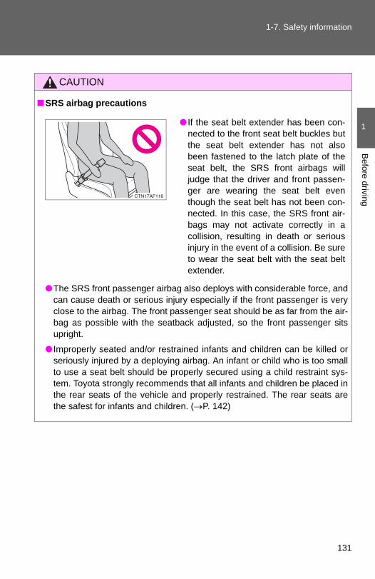
1-7. Safety information
1
Before driving
CAUTION
■SRS airbag precautions
●The SRS front passenger airbag also deploys with considerable force, andcan cause death or serious injury especially if the front passenger is veryclose to the airbag. The front passenger seat should be as far from the air-bag as possible with the seatback adjusted, so the front passenger sitsupright.
● Improperly seated and/or restrained infants and children can be killed orseriously injured by a deploying airbag. An infant or child who is too smallto use a seat belt should be properly secured using a child restraint sys-tem. Toyota strongly recommends that all infants and children be placed inthe rear seats of the vehicle and properly restrained. The rear seats arethe safest for infants and children. (→P. 142)
● If the seat belt extender has been con-nected to the front seat belt buckles butthe seat belt extender has not alsobeen fastened to the latch plate of theseat belt, the SRS front airbags willjudge that the driver and front passen-ger are wearing the seat belt eventhough the seat belt has not been con-nected. In this case, the SRS front air-bags may not activate correctly in acollision, resulting in death or seriousinjury in the event of a collision. Be sureto wear the seat belt with the seat beltextender.
131
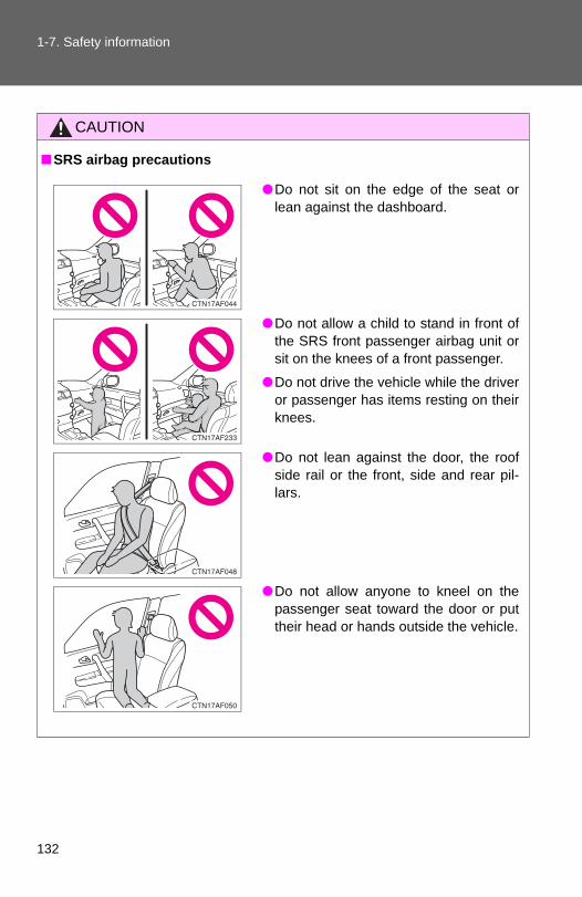
1-7. Safety information
CAUTION
■SRS airbag precautions
●Do not sit on the edge of the seat orlean against the dashboard.
●Do not allow a child to stand in front ofthe SRS front passenger airbag unit orsit on the knees of a front passenger.
●Do not drive the vehicle while the driveror passenger has items resting on theirknees.
●Do not lean against the door, the roofside rail or the front, side and rear pil-lars.
●Do not allow anyone to kneel on thepassenger seat toward the door or puttheir head or hands outside the vehicle.
132

1-7. Safety information
1
Before driving
CAUTION
■SRS airbag precautions
● If the vinyl cover is put on the area where the SRS knee airbag will deploy,be sure to remove it.
●Do not use seat accessories which cover the parts where the SRS sideairbags inflate as they may interfere with inflation of the airbags.
●Do not strike or apply significant levels of force to the area of the SRS air-bag components (→P. 124).Doing so can cause the SRS airbags to malfunction.
●Do not attach anything to or lean any-thing against areas such as the dash-board, steering wheel pad or lowerportion of the instrument panel. These items can become projectileswhen SRS driver, front passenger andknee airbags deploy.
●Do not attach anything to areas such asthe door, windshield glass, side doorglass, front and rear pillars, roof siderail or assist grip.
●Do not hang coat hangers or other hardobjects on the coat hooks. All of theseitems could become projectiles andseriously injure or kill you, should theSRS curtain shield airbag deploy.
●Vehicles without smart key system: Donot attach any heavy, sharp or hardobjects such as keys or accessories tothe key. The objects may restrict theSRS knee airbag inflation or be thrustinto the driver's seat area by the forceof the deploying airbag, thus causing adanger.
133

1-7. Safety information
CAUTION
■SRS airbag precautions●Do not touch any of the component parts immediately after the SRS air-
bags have deployed (inflated) as they may be hot.
● If breathing becomes difficult after the SRS airbag has deployed, open adoor or window to allow fresh air in, or leave the vehicle if it is safe to doso. Wash off any residue as soon as possible to prevent skin irritation.
● If the areas where the SRS airbags are stored, such as the steering wheelpad and front and rear pillar garnishes, are damaged or cracked, havethem replaced by your Toyota dealer.
■Modification and disposal of SRS airbag system componentsDo not dispose of your vehicle or perform any of the following modificationswithout consulting your Toyota dealer. The SRS airbags may malfunction or deploy (inflate) accidentally, causingdeath or serious injury.
● Installation, removal, disassembly and repair of the SRS airbags.
●Repairs, modifications, removal or replacement of the steering wheel,instrument panel, dashboard, seats or seat upholstery, front, side and rearpillars or roof side rails.
●Repairs or modifications of the front fender, front bumper, or side of theoccupant compartment.
● Installation of snow plows, winches, etc. to the front grille (bull bars, kan-garoo bar etc.).
●Modifications to the vehicle's suspension system.
● Installation of electronic devices such as mobile two-way radios or CDplayers.
●Modifications to your vehicle for a person with a physical disability.
134

1
Before driving
1-7. Safety information
Front passenger occupant classification system
Your vehicle is equipped with a front passenger occupant classifica-tion system. This system detects the conditions of the front passen-ger seat and activates or deactivates the devices for the frontpassenger.
Vehicles without navigation system
135

1-7. Safety information
Vehicles with navigation system
SRS warning light“AIR BAG OFF” indicator light“AIR BAG ON” indicator lightFront passenger's seat belt reminder light
136
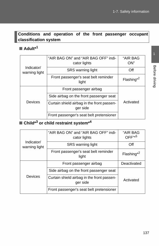
1-7. Safety information
1
Before driving
Conditions and operation of the front passenger occupantclassification system
■ Adult*1
■ Child*3 or child restraint system*4
Indicator/warning light
“AIR BAG ON” and “AIR BAG OFF” indi-cator lights
“AIR BAG ON”
SRS warning light Off
Front passenger's seat belt reminder light Flashing*2
Devices
Front passenger airbag
ActivatedSide airbag on the front passenger seat
Curtain shield airbag in the front passen-ger side
Front passenger's seat belt pretensioner
Indicator/warning light
“AIR BAG ON” and “AIR BAG OFF” indi-cator lights
“AIR BAG OFF”*5
SRS warning light Off
Front passenger's seat belt reminder light Flashing*2
Devices
Front passenger airbag Deactivated
Side airbag on the front passenger seat
ActivatedCurtain shield airbag in the front passen-ger side
Front passenger's seat belt pretensioner
137

1-7. Safety information
■ Unoccupied
■ There is a malfunction in the system
*1: The system judges a person of adult size as an adult. When asmaller adult sits in the front passenger seat, the system may rec-ognize him/her as a child depending on his/her physique and pos-ture.
*2: In the event the front passenger does not wear a seat belt.
*3: When a larger child who has outgrown a child restraint systemsits in the front passenger seat, the system may recognize him/her as an adult depending on his/her physique or posture.
Indicator/warning light
“AIR BAG ON” and “AIR BAG OFF” indi-cator lights
Not illumi-nated
SRS warning lightOffFront passenger's seat belt reminder
light
Devices
Front passenger airbag Deactivated
Side airbag on the front passenger seatActivatedCurtain shield airbag in the front passen-
ger side
Front passenger's seat belt pretensioner Deactivated
Indicator/warning light
“AIR BAG ON” and “AIR BAG OFF” indi-cator lights
“AIR BAG OFF”
SRS warning light On
Front passenger's seat belt reminder light Off
Devices
Front passenger airbag Deactivated
Side airbag on the front passenger seat
ActivatedCurtain shield airbag in the front passen-ger side
Front passenger's seat belt pretensioner
138

1-7. Safety information
1
Before driving
*4: Never install a rear-facing child restraint system on the front pas-senger seat. A forward-facing child restraint system should onlybe installed on the front passenger seat when it is unavoidable.(→P. 143)
*5: In case the indicator is not illuminated, consult this manual as forinstalling the child restraint system properly. (→P. 147)
139

1-7. Safety information
CAUTION
■Front passenger occupant classification system precautionsObserve the following precautions regarding front passenger occupant clas-sification system. Failure to do so may cause death or serious injury.
●Wear the seat belt properly.
●Make sure the front passenger's seat belt tab has not been left insertedinto the buckle before someone sits in the front passenger seat.
●Make sure the “AIR BAG OFF” indicator light is not illuminated when usingthe seat belt extender for the front passenger seat. If the “AIR BAG OFF”indicator light is illuminated, disconnect the extender tongue from the seatbelt buckle, then reconnect the seat belt. Reconnect the seat belt extenderafter making sure the “AIR BAG ON” indicator light is illuminated. If youuse the seat belt extender while the “AIR BAG OFF” indicator light is illumi-nated, the SRS airbags for the passenger may not activate correctly,which could cause death or serious injury in the event of a collision.
●Do not apply a heavy load to the front passenger seat or equipment (e.g.seatback pocket).
●Do not put weight on the front passenger seat by putting your hands orfeet on the front passenger seat seatback from the rear passenger seat.
●Do not let a rear passenger lift the front passenger seat with their feet orpress on the seatback with their legs.
●Do not put objects under the front passenger seat.
●Do not recline the front passenger seatback so far that it touches a rearseat. This may cause the “AIR BAG OFF” indicator light to be illuminated,which indicates that the passenger's airbags will not deploy in the event ofa severe accident. If the seatback touches the rear seat, return the seat-back to a position where it does not touch the rear seat. Keep the frontpassenger seatback as upright as possible when the vehicle is moving.Reclining the seatback excessively may lessen the effectiveness of theseat belt system.
140

1-7. Safety information
1
Before driving
CAUTION
■Front passenger occupant classification system precautions● If an adult sits in the front passenger seat, the “AIR BAG ON” indicator
light is illuminated. If the “AIR BAG OFF” indicator is illuminated, ask thepassenger to sit up straight, well back in the seat, feet on the floor, andwith the seat belt worn correctly. If the “AIR BAG OFF” indicator stillremains illuminated, either ask the passenger to move to the rear seat, orif that is not possible, move the front passenger seat fully rearward.
●When it is unavoidable to install the forward-facing child restraint systemon the front passenger seat, install the child restraint system on the frontpassenger seat in the proper order. (→P. 147)
●Do not modify or remove the front seats.
●Do not kick the front passenger seat or subject it to severe impact. Other-wise, the SRS warning light may come on to indicate a malfunction of thedetection system. In this case, contact your Toyota dealer immediately.
●Child restraint systems installed on the rear seat should not contact thefront seatbacks.
●Do not use a seat accessory, such as a cushion or seat cover, that coversthe seat cushion surface.
●Do not modify or replace the upholstery of the front seat.
141

1-7. Safety information
Child restraint systems
Points to remember
Studies have shown that installing a child restraint on a rear seat ismuch safer than installing one to the front passenger seat.
● Choose a child restraint system that suits your vehicle and isappropriate to the age and size of the child.
● For installation details, follow the instructions provided with thechild restraint system.General installation instructions are provided in this manual. (→P. 147)
A child restraint system for a small child or baby must itself be prop-erly restrained on the seat with the lap portion of the lap/shoulderbelt.
The laws of all 50 states of the U.S.A. and Canada now require theuse of child restraint systems.
142

1-7. Safety information
1
Before driving
Types of child restraints
Child restraint systems are classified into the following 3 typesaccording to the age and size of the child.
Rear facing ⎯ Infant seat/convertible seat
Forward facing ⎯ Convertible seat
Booster seat
143
1-7. Safety information
■Selecting an appropriate child restraint system●Use a child restraint system appropriate for the child until the child
becomes large enough to properly wear the vehicle’s seat belt.
● If a child is too large for a child restraint system, sit the child on a rearseat and use the vehicle's seat belt. (→P. 88)
CAUTION
■Child restraint precautions●For effective protection in automobile accidents and sudden stops, a child
must be properly restrained, using a seat belt or child restraint systemdepending on the age and size of the child. Holding a child in your arms isnot a substitute for a child restraint system. In an accident, the child can becrushed against the windshield, or between you and the vehicle's interior.
●Toyota strongly urges the use of a proper child restraint system that con-forms to the size of the child, installed on the rear seat. According to acci-dent statistics, the child is safer when properly restrained in the rear seatthan in the front seat.
●Never install a rear-facing child restraint system on the front passengerseat even if “AIR BAG OFF” indicator light is illuminated. In the event of an accident, the force of the rapid inflation of the front pas-senger airbag can cause death or serious injury to the child if the rear-fac-ing child restraint system is installed on the front passenger seat.
144

1-7. Safety information
1
Before driving
CAUTION
■Child restraint precautions●A forward-facing child restraint system may be allowed to be installed on
the front passenger seat only when it is unavoidable. A child restraint sys-tem that requires a top tether strap should not be used in the front passen-ger seat since there is no top tether strap anchor for the front passengerseat. Adjust the seatback as uprights as possible and always move theseat as far back as possible even if the “AIR BAG OFF” indicator light isilluminated, because the front passenger airbag could inflate with consid-erable speed and force. Otherwise, the child may be killed or seriouslyinjured.
●Do not use the seat belt extender when installing a child restraint systemon the front or rear passenger seat. If installing a child restraint systemwith the seat belt extender connected to the seat belt, the seat belt will notsecurely hold the child restraint system, which could cause death or seri-ous injury to the child or other passengers in the event of a sudden stop,sudden swerve or accident.
●Do not allow the child to lean his/her head or any part of his/her bodyagainst the door or the area of the seat, front and rear pillars or roof siderail from which the side airbags or curtain shield airbags deploy even if thechild is seated in the child restraint system. It is dangerous if the side air-bags and curtain shield airbags inflate, and the impact could cause deathor serious injury to the child.
●Make sure you have complied with all installation instructions provided bythe child restraint manufacturer and that the system is properly secured. Ifit is not secured properly, it may cause death or serious injury to the childin the event of a sudden stop, sudden swerve or accident.
■When children are in the vehicleDo not allow children to play with the seat belt. If the seat belt becomestwisted around a child’s neck, it may lead to choking or other serious injuriesthat could result in death.If this occurs and the buckle cannot be unfastened, scissors should be usedto cut the belt.
145

1-7. Safety information
CAUTION
■When the child restraint system is not in use●Keep the child restraint system properly secured on the seat even if it is
not in use.Do not store the restraint unsecured in the passenger compartment.
● If it is necessary to detach the child restraint system, remove it from thevehicle or store it securely in the luggage compartment. This will prevent itfrom injuring passengers in the event of a sudden stop, sudden swerve oraccident.
146

1
Before driving
1-7. Safety information
Installing child restraints
Follow the child restraint system manufacturer's instructions. Firmlysecure child restraints to the rear seats using the LATCH anchors ora seat belt. Attach the top tether strap when installing a childrestraint.
The lap/shoulder belt can be used if your child restraint system isnot compatible with the LATCH (Lower Anchors and Tethers for Chil-dren) system.
Second seat: Child restraintLATCH anchors
LATCH anchors are providedfor the rear outer seats. (But-tons displaying the location ofthe anchors are attached to theseats.)
Seat belts equipped with achild restraint locking mecha-nism (ALR/ELR belts exceptdriver’s seat belt)
147

1-7. Safety information
Second seat: Anchor brackets(for top tether strap)
Anchor brackets are providedfor the second seats.
148

1-7. Safety information
1
Before driving
Installation with LATCH system
Fold the seatback while pullingthe lever. Return the seatbackand secure it at the 1st lock posi-tion (most upright position).Adjust the seatback to the 3rdlock position. (→P. 77)
1st lock position3rd lock position
Type A
Latch the hooks of the lowerstraps onto the LATCH anchors.
The bars are installed in theclearance between the seat cush-ion and seatback.
If the child restraint has a toptether strap, the top tether strapshould be latched onto the toptether strap anchors.
For owners in Canada:The symbol on a child restraintsystem indicates the presence ofa lower connector system.
STEP 1
STEP 2
Canada only
149

1-7. Safety information
Type B
Latch the buckles onto theLATCH anchors.
The bars are installed in theclearance between the seat cush-ion and seatback.
If the child restraint has a toptether strap, the top tether strapshould be latched onto the toptether strap anchors.
For owners in Canada:The symbol on a child restraintsystem indicates the presence ofa lower connector system.
Canada only
STEP 2
150
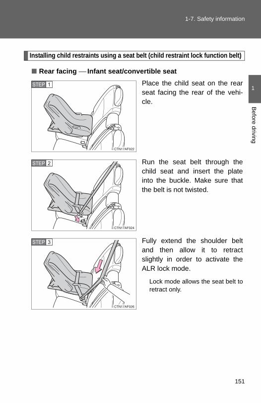
1-7. Safety information
1
Before driving
Installing child restraints using a seat belt (child restraint lock function belt)
■ Rear facing ⎯ Infant seat/convertible seatPlace the child seat on the rearseat facing the rear of the vehi-cle.
Run the seat belt through thechild seat and insert the plateinto the buckle. Make sure thatthe belt is not twisted.
Fully extend the shoulder beltand then allow it to retractslightly in order to activate theALR lock mode.
Lock mode allows the seat belt toretract only.
STEP 1
STEP 2
STEP 3
151

1-7. Safety information
While pushing the child seatdown into the rear seat, allow theshoulder belt to retract until thechild seat is securely in place.
After the shoulder belt hasretracted to a point where there isno slack in the belt, pull the belt tocheck that it cannot be extended.
■ Forward facing ⎯ Convertible seatPlace the child seat on the seatfacing the front of the vehicle.
Run the seat belt through thechild seat and insert the plateinto the buckle. Make sure thatthe belt is not twisted.
Fully extend the shoulder strapand then allow it to retractslightly into the ALR lock mode.
Lock mode allows the seat belt toretract only.
STEP 4
STEP 1
STEP 2
STEP 3
152

1-7. Safety information
1
Before driving
While pushing the child seat intothe rear seat, allow the shoulderbelt to retract until the child seatis securely in place.
After the shoulder belt hasretracted to a point where there isno slack in the belt, pull the belt tocheck that it cannot be extended.
If the child restraint has a top tether strap, the top tether strapshould be latched onto the top tether strap anchors.
■ Booster seatPlace the booster seat on theseat facing the front of the vehi-cle.
Sit the child in the booster seat.Fit the seat belt to the boosterseat according to the manufac-turer's instructions and insert theplate into the buckle. Make surethat the belt is not twisted.
Check that the shoulder belt iscorrectly positioned over thechild's shoulder, and that the lapbelt is as low as possible. (→P. 88)
STEP 4
STEP 5
STEP 1
STEP 2
153

1-7. Safety information
Removing a child restraint installed with a seat belt
Push the buckle release buttonand fully retract the seat belt.
Child restraint systems with a top tether strap (second seat only)
Secure the child restraint usingthe seat belt or lower anchors,and adjust the head restraint tothe upmost position.
STEP 1
154

1-7. Safety information
1
Before driving
Outer seat: Open the anchorbracket cover, latch the hookonto the anchor bracket andtighten the top tether strap.
Center seat: Latch the hook ontothe anchor bracket and tightenthe top tether strap.
Make sure the top tether strap issecurely latched.
Adjust the head restraint to thedownmost position.
STEP 2
STEP 3
■Laws and regulations pertaining to anchoragesThe LATCH system conforms to FMVSS225 or CMVSS210.2.Child restraint systems conforming to FMVSS213 or CMVSS213 specifica-tions can be used.This vehicle is designed to conform to the SAE J1819.
155

1-7. Safety information
CAUTION
■When installing a booster seatDo not fully extend the shoulder belt to prevent the belt from going to ALRlock mode. (→P. 89)
ALR mode causes the belt to tighten only which could cause injury or dis-comfort to the child.
■When installing a child restraint systemFollow the directions given in the child restraint system installation manualand fix the child restraint system securely in place.If the child restraint system is not correctly fixed in place, the child or otherpassengers may be seriously injured or even killed in the event of suddenbraking, sudden swerving or an accident.
● If the driver's seat interferes with thechild restraint system and prevents itfrom being attached correctly, attachthe child restraint system to the right-hand rear seat.
●Adjust the front passenger seat or sec-ond seats so that it does not interferewith the child restraint system.
●Only put a forward-facing or boosterchild seat on the front seat whenunavoidable. When installing a forward-facing or booster child seat on the frontpassenger seat, move the seat as farback as possible even if “AIR BAGOFF” indicator light is illuminated. Fail-ing to do so may result in death or seri-ous injury if the airbags deploy (inflate).
156

1-7. Safety information
1
Before driving
CAUTION
■When installing a child restraint system●When installing a child restraint system in the rear center seat, adjust both
seat cushions to the same position and align seatbacks at the same angle.The seatbacks must be adjusted to the same angle. Otherwise, the childrestraint system cannot be securely restrained and this may cause deathor serious injuries in the event of sudden braking, sudden swerving or anaccident.
●When using the LATCH anchors for a child restraint system, move the seatas far back as possible (second seat only), with the seatback close to thechild restraint system.
●When a booster seat is installed, always ensure that the shoulder belt ispositioned across the center of the child's shoulder. The belt should bekept away from the child's neck, but not so that it could fall off the child'sshoulder. Failing to do so may result in death or serious injury in the eventof sudden braking, sudden swerving or an accident.
●Ensure that the belt and tab are securely locked and the seat belt is nottwisted.
●Push and pull the child seat from side to side and forward to be sure it issecure.
●After securing a child restraint system, never adjust the seat.
●Follow all installation instructions provided by the child restraint systemmanufacturer.
■Do not use a seat belt extenderIf a seat belt extender is used when installing a child restraint system, theseat belt will not securely hold the child restraint system, which could causedeath or serious injury to the child or other passengers in the event of sud-den braking, sudden swerving or an accident.
■To correctly attach a child restraint system to the anchorsWhen using the LATCH anchors, be sure that there are no foreign objectsaround the anchors and that the seat belt is not caught behind the childrestraint. Make sure the child restraint system is securely attached, or it maycause death or serious injury to the child or other passengers in the event ofa sudden stop, sudden swerve or accident.
157

1-7. Safety information
158

2-1. Driving procedures
Driving the vehicle
The following procedures should be observed to ensure safe driv-ing.
■ Starting the engine→P. 170, 174
■ DrivingWith the brake pedal depressed, shift the shift lever to D.
(→P. 177)Release the parking brake. (→P. 183)
Gradually release the brake pedal and gently depress theaccelerator pedal to accelerate the vehicle.
■ StoppingWith the shift lever in D, depress the brake pedal.If necessary, set the parking brake.When the vehicle is stopped for an extended period of time, shiftthe shift lever to P or N. (→P. 177)
■ Parking the vehicleWith the shift lever in D, depress the brake pedal.Set the parking brake. (→P. 183)Shift the shift lever to P. (→P. 177)When parking on a hill, if necessary, block the wheels.
Vehicles without smart key system:Turn the engine switch to the “LOCK” position to stop theengine.Vehicles with smart key system:Turn the “ENGINE START STOP” switch OFF to stop theengine.Lock the door, making sure that you have the key on yourperson.
STEP 1
STEP 2
STEP 3
STEP 1
STEP 2
STEP 1
STEP 2
STEP 3
STEP 4
STEP 5
160

2-1. Driving procedures
2
When driving
Starting on a steep uphill
Firmly set the parking brake and shift the shift lever to D.Gently depress the accelerator pedal.Release the parking brake.
■Driving in the rain●Drive carefully when it is raining, because visibility will be reduced, the
windows may become fogged-up, and the road will be slippery.
●Drive carefully when it starts to rain, because the road surface will beespecially slippery.
●Refrain from high speeds when driving on an expressway in the rain,because there may be a layer of water between the tires and the roadsurface, preventing the steering and brakes from operating properly.
■Breaking in your new ToyotaTo extend the life of the vehicle, observing the following precautions is rec-ommended:
●For the first 186 miles (300 km): Avoid sudden stops.
●For the first 500 miles (800 km):Do not tow a trailer.
●For the first 621 miles (1000 km):
• Do not drive at extremely high speeds.• Avoid sudden acceleration.• Do not drive continuously in the low gears.• Do not drive at a constant speed for extended periods.
■Drum-in-disc type parking brake systemYour vehicle has a drum-in-disc type parking brake system.This type of brake system needs bedding-down of the brake shoes periodi-cally or whenever the parking brake shoes and/or drums are replaced.
Have your Toyota dealer perform the bedding-down.
STEP 1
STEP 2
STEP 3
161

2-1. Driving procedures
■Operating your vehicle in a foreign countryComply with the relevant vehicle registration laws and confirm the availabilityof the correct fuel. (→P. 575)
CAUTION
■When starting the vehicleAlways keep your foot on the brake pedal while stopped with the engine run-ning. This prevents the vehicle from creeping.
■When driving the vehicle●Do not drive if you are unfamiliar with the location of the brake and accel-
erator pedals to avoid depressing the wrong pedal.
• Accidentally depressing the accelerator pedal instead of the brakepedal will result in sudden acceleration that may lead to an accidentthat could result in death or serious injury.
• When backing up, you may twist your body around, leading to a diffi-culty in operating the pedals. Make sure to operate the pedals properly.
• Make sure to keep a correct driving posture even when moving thevehicle only slightly, allowing you to depress the brake and acceleratorpedals properly.
• Depress the brake pedal using your right foot. Depressing the brakepedal using your left foot may delay response in an emergency, result-ing in an accident.
●Do not drive the vehicle over or stop the vehicle near flammable materials.The exhaust system and exhaust gases can be extremely hot. This maycause a fire if there is any flammable material nearby.
●Do not let the vehicle roll backwards while the shift lever is in a drivingposition, or roll forward while the shift lever is in R.Doing so may cause the engine to stall or lead to poor brake and steeringperformance, resulting in an accident or damage to the vehicle.
● If the smell of exhaust is noticed inside the vehicle, open the windows andcheck that the back door is closed. Large amounts of exhaust in the vehi-cle can cause driver drowsiness and an accident, resulting in death or aserious health hazard. Have the vehicle inspected by your Toyota dealerimmediately.
162

2-1. Driving procedures
2
When driving
CAUTION
●Do not shift the shift lever to P while the vehicle is moving.Doing so can damage the transmission and may result in a loss of vehiclecontrol.
●Do not shift the shift lever to R while the vehicle is moving forward.Doing so can damage the transmission and may result in a loss of vehiclecontrol.
●Do not shift the shift lever to D while the vehicle is moving backward.Doing so can damage the transmission and may result in a loss of vehiclecontrol.
●Moving the shift lever to N while the vehicle is moving will disengage theengine from the transmission. Engine braking is not available when N isselected.
●During normal driving, do not turn off the engine. Turning the engine offwhile driving will not cause loss of steering or braking control, but thepower assist to these systems will be lost. This will make it more difficult tosteer and brake, so you should pull over and stop the vehicle as soon as itis safe to do so.However, in the event of an emergency, such as if it becomes impossibleto stop the vehicle in the normal way: →P. 569
●Use engine braking (downshift) to maintain a safe speed when drivingdown a steep hill.Using the brakes continuously may cause the brakes to overheat and loseeffectiveness. (→P. 178)
●When stopped on an inclined surface, use the brake pedal and parkingbrake to prevent the vehicle from rolling backward or forward and causingan accident.
●Do not adjust the position of the steering wheel, the seat, or the inside oroutside rear view mirrors while driving.Doing so may result in a loss of vehicle control that can cause accidentsthat may result in death or serious injury.
●Always check that all passengers' arms, heads or other parts of their bod-ies are not outside the vehicle, as this may result in death or serious injury.
●Do not drive the vehicle off-road.This is not a 4WD vehicle designed for real off-road driving. Proceed withall due caution if it becomes unavoidable to drive off-road.
163

2-1. Driving procedures
CAUTION
●4WD models: Do not drive across a river or through other bodies of water.This may cause electric/electronic components to short circuit, damagethe engine or cause other serious damage to the vehicle.
●Do not drive in excess of the speed limit. Even if the legal speed limit per-mits it, do not drive over 85 mph (140 km/h) unless your vehicle has high-speed capability tires. Driving over 85 mph (140 km/h) may result in tirefailure, loss of control and possible injury. Be sure to consult a tire dealerto determine whether the tires on your vehicle are high-speed capabilitytires or not before driving at such speeds.
■When driving on slippery road surfaces●Sudden braking, acceleration and steering may cause tire slippage and
reduce your ability to control the vehicle, resulting in an accident.
●Sudden changes in engine speed, such as engine braking caused by up-shifting or down-shifting, may cause the vehicle to skid, resulting in anaccident.
●After driving through a puddle, lightly depress the brake pedal to makesure that the brakes are functioning properly. Wet brake pads may preventthe brakes from functioning properly. If the brakes on only one side are wetand not functioning properly, steering control may be affected, resulting inan accident.
■When shifting the shift leverBe careful not to shift the shift lever with the accelerator pedal depressed.This may lead to unexpected rapid acceleration of the vehicle that maycause an accident and result in death or serious injury.
■When the vehicle is stopped●Do not race the engine.
If the vehicle is in any gear other than P or N, the vehicle may acceleratesuddenly and unexpectedly, and may cause an accident.
●Do not leave the vehicle with the engine running for a long time.If such a situation cannot be avoided, park the vehicle in an open spaceand check that exhaust fumes do not enter the vehicle interior.
164

2-1. Driving procedures
2
When driving
CAUTION
● In order to prevent accidents due to the vehicle rolling away, always keepdepressing the brake pedal while the engine is running, and apply theparking brake as necessary.
● If the vehicle is stopped on an incline, in order to prevent accidents causedby the vehicle rolling forward or backward, always depress the brake pedaland securely apply the parking brake as needed.
●Avoid revving or racing the engine.Running the engine at high speed while the vehicle is stopped may causethe exhaust system to overheat, which could result in a fire if combustiblematerial is nearby.
■When the vehicle is parked●Do not leave glasses, cigarette lighters, spray cans, or soft drink cans in
the vehicle when it is in the sun.Doing so may result in the following.
• Gas may leak from a cigarette lighter or spray can, and may lead to afire.
• The temperature inside the vehicle may cause the plastic lenses andplastic material of eye glasses to deform or crack.
• Soft drink cans may fracture, causing the contents to spray over theinterior of the vehicle, and may also cause a short circuit in the vehi-cle's electrical components.
●Do not leave cigarette lighters in the vehicle. If a cigarette lighter is in aplace such as the glove box or on the floor, it may be lit accidentally whenluggage is loaded or the seat is adjusted, causing a fire.
●Do not attach adhesive discs to the windshield or windows. Do not placecontainers such as air fresheners on the instrument panel or dashboard.Adhesive discs or containers may act as lenses, causing a fire in the vehi-cle.
●Do not leave a door or window open if the curved glass is coated with ametallized film such as a silver-colored one. Reflected sunlight may causethe glass to act as a lens, causing a fire.
165

2-1. Driving procedures
CAUTION
●Always apply the parking brake, shift the shift lever to P, stop the engineand lock the vehicle.Do not leave the vehicle unattended while the engine is running.
●Do not touch the exhaust pipe while the engine is running or immediatelyafter turning the engine off. Doing so may cause burns.
●Do not leave the engine running in an area with snow build-up, or where itis snowing. If snowbanks build up around the vehicle while the engine isrunning, exhaust gases may collect and enter the vehicle. This may leadto death or a serious health hazard.
■Exhaust gasesExhaust gases include harmful carbon monoxide (CO) that is colorless andodorless. Inhaling exhaust gases may lead to death or a serious health haz-ard.
● If the vehicle is in a poorly ventilated area, stop the engine. In a closedarea, such as a garage, exhaust gases may collect and enter the vehicle.This may lead to death or a serious health hazard.
●The exhaust should be checked occasionally. If there is a hole or crackcaused by corrosion, damage to a joint or abnormal exhaust noise, besure to have the vehicle inspected and repaired by your Toyota dealer.Failure to do so may allow exhaust gases to enter the vehicle, resulting indeath or a serious health hazard.
■When taking a nap in the vehicleAlways turn the engine off. Otherwise, you may accidentally move the shiftlever or depress the accelerator pedal, which could cause an accident or firedue to engine overheating. Additionally, if the vehicle is parked in a poorlyventilated area, exhaust gases may collect and enter the vehicle, leading todeath or a serious health hazard.
166

2-1. Driving procedures
2
When driving
CAUTION
■When braking the vehicle●When the brakes are wet, drive more cautiously.
Braking distance increases when the brakes are wet, and may cause oneside of the vehicle to brake differently than the other side. Also the parkingbrake may not securely hold the vehicle.
● If the power brake assist function does not operate, do not follow othervehicles closely and avoid downhills or sharp turns that require braking.In this case, braking is still possible, but it will require more force on thepedal than usual. Braking distance may also increase.
●Do not pump the brake pedal if the engine stalls. Each push on the brake pedal uses up the reserve for the power-assistedbrakes.
●The brake system consists of 2 individual hydraulic systems: If one of thesystems fails, the other will still operate. In this case, the brake pedalshould be depressed more firmly than usual and braking distancebecomes longer.Do not drive your vehicle with only a single brake system. Have yourbrakes fixed immediately.
■ If the vehicle becomes stuck or bogged (4WD models)Do not spin the wheels recklessly when any of the tires is up in the air, orstuck in sand or mud etc. This may damage the drive system components orpropel the vehicle forward (or in another direction) and cause an accident.
■ If you hear a squealing or scraping noise (brake pad wear limit indica-tors)Have the brake pads checked and replaced by your Toyota dealer as soonas possible. Rotor damage can result if the pads are not replaced when needed.
It is dangerous to drive the vehicle when the wear limits of the brake padsand/or those of the brake discs are exceeded.
167
2-1. Driving procedures
CAUTION
■ If you get a flat tire while drivingA flat or damaged tire may cause the following situations. Hold the steeringwheel firmly and gradually press the brake pedal to slow down the vehicle.
● It may be difficult to control your vehicle.
●The vehicle will make abnormal sounds.
●The vehicle will behave abnormally.
Replace a flat tire with a new one. (→P. 545)
NOTICE
■When driving the vehicle●Do not depress the accelerator and brake pedals at the same time during
driving. If the brake pedal is depressed while driving with the acceleratorpedal depressed, driving torque may be restrained.
●Do not use the accelerator pedal or depress the accelerator and brakepedals together to hold the vehicle on a hill.
■When parking the vehicleAlways put the shift lever in P. Failure to do so may cause the vehicle tomove or the vehicle may accelerate suddenly if the accelerator pedal is acci-dentally depressed.
■Avoiding damage to vehicle parts●Do not turn the steering wheel fully in either direction and hold it there for a
long time. Doing so may damage the power steering motor.
●When driving over bumps in the road, drive as slowly as possible to avoiddamaging the wheels, underside of the vehicle, etc.
168

2-1. Driving procedures
2
When driving
NOTICE
■When encountering flooded roadsDo not drive on a road that has flooded after heavy rain etc. Doing so maycause the following serious damage to the vehicle.
●Engine stalling
●Short in electrical components
●Engine damage caused by water immersion
In the event that you drive on a flooded road and the vehicle is flooded, besure to have your Toyota dealer check the following.
●Brake function
●Changes in quantity and quality of oil and fluid used for the engine, tran-saxle, transfer (4WD models), differential (4WD models), etc.
●Lubricant condition for the propeller shaft (4WD models), bearings andsuspension joints (where possible) and the function of all joints, bearings,etc.
169

2-1. Driving procedures
Engine (ignition) switch (vehicles with smart key system)
Performing the following operations when carrying the electronickey on your person starts the engine or changes “ENGINE STARTSTOP” switch mode.
■ Starting the engineThe engine can be started in any mode by operating the “ENGINESTART STOP” switch at the same time as depressing the brakepedal.
Check that the parking brake is set.Check that the shift lever is set in P.Sit in the driver’s seat and firmly depress the brake pedal.The “ENGINE START STOP” switch indicator turns green. If theindicator does not turn green, the engine cannot be started.
Press the “ENGINE STARTSTOP” switch.
The engine can be startedfrom any “ENGINE STARTSTOP” switch mode.
Continue depressing the brakepedal until the engine is com-pletely started.
The engine will crank until itstarts or for up to 30 seconds,whichever is less.
STEP 1
STEP 2
STEP 3
STEP 4
170

2-1. Driving procedures
2
When driving
■ Changing “ENGINE START STOP” switch modesModes can be changed by pressing the “ENGINE START STOP”switch with the brake pedal released. (The mode changes eachtime the switch is pressed.)
OFF*
The emergency flashers canbe used.
ACCESSORY mode
Some electrical componentssuch as the audio system canbe used.
The “ENGINE START STOP”switch indicator turns amber.
IGNITION ON mode
All electrical components canbe used.
The “ENGINE START STOP”switch indicator turns amber.
*: If the shift lever is in a positionother than P when turning offthe engine, the “ENGINESTART STOP” switch will beturned to ACCESSORY mode,not to OFF.
171

2-1. Driving procedures
■Steering lock release
■ If the engine does not startThe engine immobilizer system may not have been deactivated. (→P. 113)
■When the “ENGINE START STOP” switch indicator flashes in amberThe system may be malfunctioning. Have the vehicle inspected by yourToyota dealer immediately.
■Auto power off functionIf the vehicle is left in ACCESSORY mode for more than an hour with theshift lever in P, the “ENGINE START STOP” switch will automatically turn off.
■Key battery depletion→P. 42
■When the electronic key battery is discharged→P. 497
■Conditions affecting operation→P. 40
■Note for the entry function→P. 42
Make sure that the steering wheel lock isreleased.
To release the steering wheel lock, gentlyturn the wheel left or right while pressingthe “ENGINE START STOP” switch.
When the steering wheel lock is notreleased, the “ENGINE START STOP”switch indicator will flash in green.
172

2-1. Driving procedures
2
When driving
CAUTION
■When starting the engineAlways start the engine while sitting in the driver's seat. Do not depress theaccelerator pedal while starting the engine under any circumstances.Doing so may cause an accident resulting in death or serious injury.
■Caution while drivingIf the vehicle begins to slide due to engine failure or other circumstances, donot lock or open the doors until the vehicle reaches a safe and completestop. Activation of the steering lock in this circumstance may lead to an acci-dent, resulting in death or serious injury.
■Stopping the engine in an emergencyIf you want to stop the engine in an emergency while driving the vehicle,press and hold the “ENGINE START STOP” switch for more than 3 seconds.However, do not touch the “ENGINE START STOP” switch while drivingexcept in an emergency. Turning the engine off while driving will not causeloss of steering or braking control, but the power assist to these systems willbe lost. This will make it more difficult to steer and brake, so you should pullover and stop the vehicle as soon as it is safe to do so.
NOTICE
■To prevent battery dischargeDo not leave the “ENGINE START STOP” switch in ACCESSORY or IGNI-TION ON mode for long periods without the engine running.
■When starting the engine●Do not race a cold engine.
● If the engine becomes difficult to start or stalls frequently, have the enginechecked immediately.
173

2-1. Driving procedures
Engine (ignition) switch (vehicles without smart key system)
■ Starting the engineCheck that the parking brake is set.Check that the shift lever is set in P.Sit in the driver’s seat and firmly depress the brake pedal.Turn the engine switch to the “START” position and startthe engine.
■ Changing engine switch position“LOCK”
The steering wheel is lockedand the key can be removed.(The key can be removed onlywhen the shift lever is in P.)
“ACC”
Some electrical componentssuch as the audio system canbe used.
“ON”
All electrical components canbe used.
“START”
For starting the engine.
STEP 1
STEP 2
STEP 3
STEP 4
174

2-1. Driving procedures
2
When driving
■Turning the key from “ACC” to “LOCK”
■Steering lock release
■ If the engine does not start (vehicles with engine immobilizer system)The engine immobilizer system may not have been deactivated. (→P. 113)
■Key reminder functionA buzzer sounds if the driver’s door is opened while the key is in the “LOCK”or “ACC” position to remind you to remove the key.
CAUTION
■When starting the engineAlways start the engine while sitting in the driver's seat. Do not depress theaccelerator while starting the engine under any circumstances.Doing so may cause an accident resulting in death or serious injury.
■Caution when drivingDo not turn the engine switch to the “LOCK” position while driving. If, in anemergency, you must turn the engine off while the vehicle is moving, turn thekey only to the “ACC” position.
Shift the shift lever to P. (→P. 177)
Push in the key and turn to the“LOCK” position.
STEP 1
STEP 2
When starting the engine, the engineswitch may seem stuck in the “LOCK”position. To free it, turn the key while turn-ing the steering wheel slightly in eitherdirection.
175

2-1. Driving procedures
NOTICE
■To prevent battery dischargeDo not leave the key in the “ACC” or “ON” position for long periods if theengine is not running.
■When starting the engine●Do not crank for more than 30 seconds at a time. This may overheat the
starter and wiring systems.
●Do not race a cold engine.
● If the engine becomes difficult to start or stalls frequently, have the enginechecked immediately.
176

2
When driving
2-1. Driving procedures
Automatic transmission
Select a shift position appropriate for the driving conditions.
■ Shifting the shift lever
Vehicles without smart key systemWhile the engine switch is in the “ON” position, depress thebrake pedal and move the shift lever.
Vehicles with smart key systemWhile the “ENGINE START STOP” switch is in IGNITIONON mode, depress the brake pedal and move the shiftlever.
177
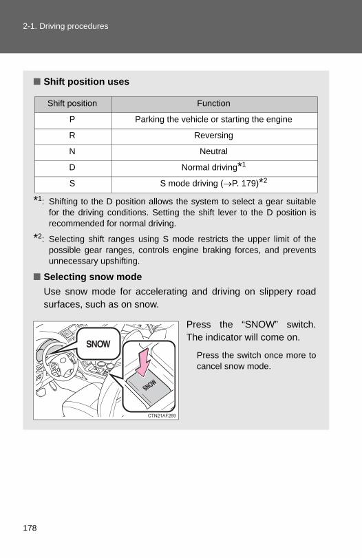
2-1. Driving procedures
■ Shift position uses
*1: Shifting to the D position allows the system to select a gear suitablefor the driving conditions. Setting the shift lever to the D position isrecommended for normal driving.
*2: Selecting shift ranges using S mode restricts the upper limit of thepossible gear ranges, controls engine braking forces, and preventsunnecessary upshifting.
■ Selecting snow modeUse snow mode for accelerating and driving on slippery roadsurfaces, such as on snow.
Press the “SNOW” switch.The indicator will come on.
Press the switch once more tocancel snow mode.
Shift position Function
P Parking the vehicle or starting the engine
R Reversing
N Neutral
D Normal driving*1
S S mode driving (→P. 179)*2
178

2-1. Driving procedures
2
When driving
Changing shift ranges in S mode
Shift the shift lever to the S position and operate the shift lever.
UpshiftingDownshifting
2.7 L 4-cylinder (1AR-FE) engineThe initial shift range in S mode is set automatically to “5” or “4”according to the vehicle speed.However, the initial shift range may be set to “3” if AI-SHIFT has oper-ated while the shift lever was in the D position. (→P. 181)
3.5 L V6 (2GR-FE) engineThe initial shift range in S mode is set automatically to “4”.However, the initial shift range may be set to “3” if AI-SHIFT has oper-ated while the shift lever was in the D position. (→P. 181)
179

2-1. Driving procedures
■ Shift ranges and their functions
A lower shift range will provide greater engine braking forces than a highershift range, and the engine speed will also increase.
■When driving with the cruise control system2.7 L 4-cylinder (1AR-FE) engine
Engine braking will not operate in S mode, even when downshifting from “6”to “5” or “5” to “4”. (→P. 215)
3.5 L V6 (2GR-FE) engineEngine braking will not operate in S mode, even when downshifting from “5”to “4”. (→P. 215)
■Snow mode automatic deactivationSnow mode is automatically deactivated if the engine is turned off after driv-ing in snow mode.
Shift rangeFunction
2.7 L 4-cylinder (1AR-FE) engine 3.5 L V6 (2GR-FE) engine
6
Automatically selecting gears between 1 and 6 according to vehicle speed and driving conditions.
⎯
5 Automatically selecting gears between 1 and 5 according to vehicle speed and driving conditions.
4 Automatically selecting gears between 1 and 4 according to vehicle speed and driving conditions.
3 Automatically selecting gears between 1 and 3 according to vehicle speed and driving conditions.
2 Automatically selecting gears between 1 and 2 according to vehicle speed and driving conditions.
1 Setting the gear at 1.
180

2-1. Driving procedures
2
When driving
■ If the shift lever cannot be shifted from P→P. 556
■ If the S indicator does not come on even after shifting the shift lever toSThis may indicate a malfunction in the automatic transmission system. Havethe vehicle inspected by your Toyota dealer immediately. (In this situation, the vehicle will operate as if the shift lever is in D.)
■Downshift restriction warning buzzer (S mode)To help ensure safety and driving performance, downshifting operation maysometimes be restricted. In some circumstances, downshifting may not bepossible even when the shift lever is operated. (A buzzer will sound twice.)
■S mode●2.7L 4-cylinder (1AR-FE) engine: when the shift range is “5” or lower,
holding the shift lever toward “+” sets the shift range to “6”.
●3.5L V6 (2GR-FE) engine: when the shift range is “4” or lower, holdingthe shift lever toward “+” sets the shift range to “5”.
●To prevent excessive engine speed, a function was adopted that auto-matically selects a higher shift range before engine speed becomes toohigh.
●To protect the automatic transmission, a function is adopted that auto-matically selects a higher shift range when the fluid temperature is high.
■AI-SHIFTAI-SHIFT automatically selects the suitable gear according to driver perfor-mance and driving conditions.AI-SHIFT automatically operates when the shift lever is in the D position.(Shifting the shift lever to the S mode driving position cancels the function.)
The engine speed may remain high after releasing the accelerator pedal.This does not indicate a malfunction.
181

2-1. Driving procedures
Turn signal lever
■Turn signals can be operated whenVehicles without smart key system
The engine switch is in the “ON” position.
Vehicles with smart key system The “ENGINE START STOP” switch is in IGNITION ON mode.
■ If the indicators flash faster than usualCheck that a light bulb in the front or rear turn signal lights has not burnedout.
Right turnLeft turnMove and hold the leverpartway to signal a lanechange.
The right hand signal will flashuntil you release the lever.
Move and hold the leverpartway to signal a lanechange.
The left hand signal will flashuntil you release the lever.
182
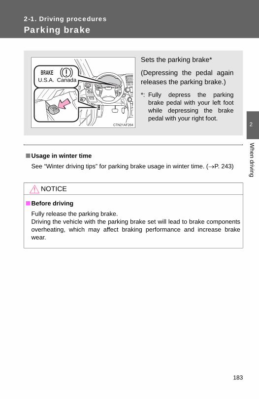
2
When driving
2-1. Driving procedures
Parking brake
■Usage in winter timeSee “Winter driving tips” for parking brake usage in winter time. (→P. 243)
NOTICE
■Before drivingFully release the parking brake.Driving the vehicle with the parking brake set will lead to brake componentsoverheating, which may affect braking performance and increase brakewear.
Sets the parking brake*
(Depressing the pedal againreleases the parking brake.)
*: Fully depress the parkingbrake pedal with your left footwhile depressing the brakepedal with your right foot.
U.S.A. Canada
183

2-1. Driving procedures
Horn
■After adjusting the steering wheelMake sure that the steering wheel is securely locked.The horn may not sound if the steering wheel is not securely locked. (→P. 94)
To sound the horn, press on orclose to the mark.
184

2-2. Instrument cluster
2
When driving
Gauges and meters
Vehicles without smart key systemThe following gauges and meters illuminate when the engineswitch is in the “ON” position.Vehicles with smart key systemThe following gauges and meters illuminate when the “ENGINESTART STOP” switch is in IGNITION ON mode.TachometerDisplays the engine speed in revolutions per minute.
Engine coolant temperature gaugeDisplays the engine coolant temperature.
Fuel gaugeDisplays the quantity of fuel remaining in the tank.
SpeedometerDisplays the vehicle speed.
Odometer/trip meter switching and trip meter resetting buttonSwitches between odometer and trip meter displays. Pushing and hold-ing the button will reset the trip meter when the trip meter is being dis-played.
185

2-2. Instrument cluster
Instrument panel light control
The brightness of the instrument panel lights can be adjusted.
BrighterDarkerWhen the headlight switch isturned on, the brightness willbe reduced slightly unless thecontrol dial is turned fully up.
Odometer/Trip meterOdometerDisplays the total distance the vehicle has been driven.Trip meterDisplays the distance the vehicle has been driven since themeter was last reset. Trip meters A and B can be used torecord and display different distances independently.
NOTICE
■To prevent damage to the engine and its components●Do not let the indicator needle of the tachometer enter the red zone, which
indicates the maximum engine speed.
●The engine may be overheating if the temperature gauge is in the redzone (H). In this case, immediately stop the vehicle in a safe place, andcheck the engine after it has cooled completely. (→P. 564)
186

2
When driving
2-2. Instrument cluster
Indicators and warning lights
The indicator and warning lights on the instrument cluster and cen-ter panel inform the driver of the status of the vehicle’s various sys-tems.
Instrument cluster
Center panel (vehicles without navigation system)
187

2-2. Instrument cluster
Center panel (vehicles with navigation system)
■ IndicatorsThe indicators inform the driver of the operating state of thevehicle’s various systems.
Turn signal indicator (→P. 182)
(U.S.A.)
Headlight indicator(→P. 200)
Headlight high beam indicator (→P. 204)
(Canada)
Tail light indicator(→P. 200)
(4WD models)
Downhill assist control system indicator (→P. 230) (if equipped)
Front fog light indicator(→P. 206)
Slip indicator (→P. 224)
“SNOW” indicator (→P. 178)
*1
*1, 2
188

2-2. Instrument cluster
2
When driving
*1: These lights turn on when the engine switch is turned to the “ON”position (vehicles without smart key system) or the “ENGINESTART STOP” switch is turned to IGNITION ON mode (vehicleswith smart key system) to indicate that a system check is being per-formed. They will turn off after the engine is started, or after a fewseconds. There may be a malfunction in a system if a light does notcome on, or if the lights do not turn off. Have the vehicle inspectedby your Toyota dealer for details.
*2: The light flashes to indicate that the system is operating.
■ Warning lightsWarning lights inform the driver of malfunctions in any of thevehicle’s systems. (→P. 528)
Shift position and shift range indica-tors (→P. 177)
SRS airbag on-off indi-cator (→P. 135)
Enhanced VSC off indi-cator (→P. 225) (if equipped)
Cruise control indicator(→P. 215)
(if equipped)
Engine immobilizer/alarm indicator (→P. 113, 116)
“TRAC OFF” indicator (→P. 224)
(Canada) (U.S.A.) (Canada) (U.S.A.) (Canada)
(U.S.A.) (U.S.A.)
(if equipped)
*1
*1
*1
*1 *1 *1 *1, 2 *1 *1 *1 *1
*1 *1, 2 *1 *1 *1, 2 *1, 2
*4 *5 *3 *1 *6
189

2-2. Instrument cluster
CAUTION
■ If a safety system warning light does not come onShould a safety system light such as the ABS and SRS airbag warning lightnot come on when you start the engine, this could mean that these systemsare not available to help protect you in an accident, which could result indeath or serious injury. Have the vehicle inspected by your Toyota dealerimmediately if this occurs.
*1: These lights turn on when the engine switch is turned to the “ON”position (vehicles without smart key system) or the “ENGINESTART STOP” switch is turned to IGNITION ON mode (vehicleswith smart key system) to indicate that a system check is being per-formed. They will turn off after the engine is started, or after a fewseconds. There may be a malfunction in a system if a light does notcome on, or if the lights do not turn off. Have the vehicle inspectedby your Toyota dealer for details.
*2: Vehicles without multi-information display
*3: Vehicles with multi-information display
*4: Vehicles without navigation system
*5: Vehicles with navigation system
*6: The light flashes to indicate a malfunction.
190
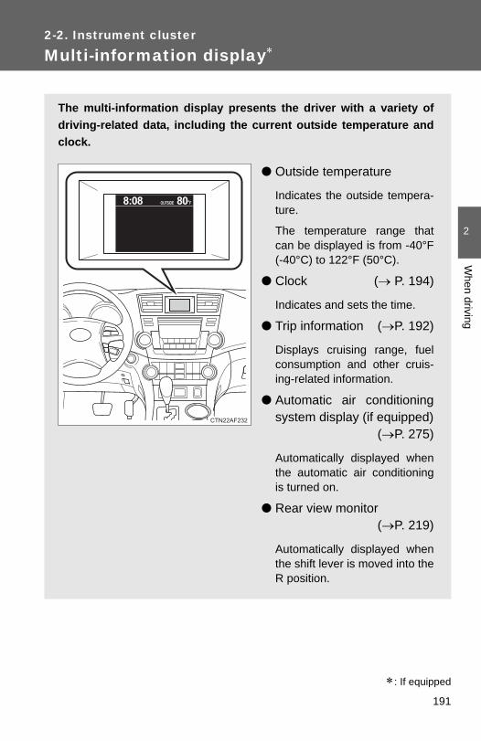
2
When driving
2-2. Instrument cluster
Multi-information display∗
The multi-information display presents the driver with a variety ofdriving-related data, including the current outside temperature andclock.
● Outside temperature
Indicates the outside tempera-ture.
The temperature range thatcan be displayed is from -40°F(-40°C) to 122°F (50°C).
● Clock (→ P. 194)
Indicates and sets the time.
● Trip information (→P. 192)
Displays cruising range, fuelconsumption and other cruis-ing-related information.
● Automatic air conditioningsystem display (if equipped)
(→P. 275)
Automatically displayed whenthe automatic air conditioningis turned on.
● Rear view monitor (→P. 219)
Automatically displayed whenthe shift lever is moved into theR position.
∗: If equipped
191

2-2. Instrument cluster
Trip information
Push the “DISP” button to dis-play trip information.
Display items can be switchedby pressing the “DISP” button.
■ Average fuel consumption after refuelingDisplays the average fuel consumption since the vehicle was lastrefueled.
Use the displayed average fuel consumption as a reference.
■ Instantaneous fuel consumptionDisplays the instantaneous fuel consumption.
● Warning messages(→P. 539)
Automatically displayed whena malfunction occurs in one ofthe vehicle’s systems.
192

2-2. Instrument cluster
2
When driving
■ Cruising rangeDisplays the estimated maximum distance that can be driven withthe quantity of fuel remaining.
• This distance is computed based on your average fuel consumption.As a result, the actual distance that can be driven may differ fromthat displayed.
• Vehicles without smart key system: When only a small amount offuel is added to the tank, the display may not be updated.When adding fuel, turn the engine switch OFF. In case fuel is addedwithout turning the engine switch OFF, the display may not beupdated.
• Vehicles with smart key system: When only a small amount of fuel isadded to the tank, the display may not be updated.When adding fuel, turn the “ENGINE START STOP” switch OFF. Incase fuel is added without turning the “ENGINE START STOP”switch OFF, the display may not be updated.
■ Driving distanceDisplays the driving distance since the engine was started.
■ Average fuel consumptionDisplays the average fuel consumption since the function wasreset.
• This function can be reset by pressing the “DISP” button for longerthan one second when the average fuel consumption is displayed. When the function is reset, the previous five average fuel consump-tion values will automatically be displayed for six seconds.
• Use the displayed average fuel consumption as a reference.
■ Average fuel consumption historyDisplays the previous five average fuel consumption values.
193

2-2. Instrument cluster
Setting up the displays
Display the set up screen on themulti-information display whenthe vehicle is stopped.
Press and hold the “DISP” buttonto display the set up screen.
Select the desired item on themenu screen.
Press and hold the “DISP” buttonto enter the setting mode.
■ Setting the clockSelect “CLOCK” on the menu screen. Press and hold the“DISP” button until the display changes.
Press the “DISP” button to adjustthe hours.
After adjusting the hours, wait 5seconds to allow the hours to beautomatically input.
STEP 1
STEP 2
STEP 1
STEP 2
194

2-2. Instrument cluster
2
When driving
Press the “DISP” button to adjustthe minutes.
After adjusting the minutes, wait 5seconds to allow the minutes tobe automatically input.
■ Setting the displaySelect “DISPLAY” on the menu screen. Press and hold the“DISP” button until the display changes.
Select the desired item on themenu screen.
Press and hold the “DISP” buttonto enter the setting mode.
● Setting day mode
Select “DAY MODE” on the menu screen. Press and hold the“DISP” button until the display changes.Press the “DISP” button to select “ON” or “OFF”.After setting day mode, wait 5 seconds to allow the mode to be auto-matically input.
● Setting the background color
Select “BACKGROUND COLOR” on the menu screen. Pressand hold the “DISP” button until the display changes.Press the “DISP” button to select “BLACK” or “BLUE”.After selecting a background color, wait 5 seconds to allow the colorto be automatically input.
STEP 3
STEP 1
STEP 2
STEP 1
STEP 2
STEP 1
STEP 2
195

2-2. Instrument cluster
● Setting the brightness
Select “BRIGHTNESS” on the menu screen. Press and holdthe “DISP” button until the display changes.
Press the “DISP” button to adjustthe brightness.
+: Brighter-: Darker
After adjusting the brightness,wait 5 seconds to allow the bright-ness to be automatically input.
● Setting the contrast
Select “CONTRAST” on the menu screen. Press and hold the“DISP” button until the display changes.
Press the “DISP” button to adjustthe contrast.
+: Strengthen-: Weaken
After adjusting the contrast, wait 5seconds to allow the contrast tobe automatically input.
● Returning to the previous screen
Select “RETURN” on the menu screen. Press and hold the “DISP”button until the display changes.
STEP 1
STEP 2
STEP 1
STEP 2
196
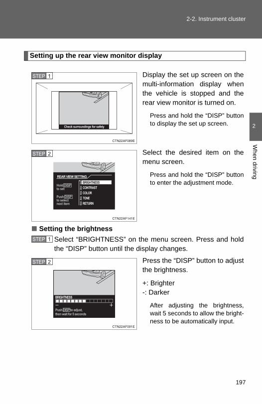
2-2. Instrument cluster
2
When driving
Setting up the rear view monitor display
Display the set up screen on themulti-information display whenthe vehicle is stopped and therear view monitor is turned on.
Press and hold the “DISP” buttonto display the set up screen.
Select the desired item on themenu screen.
Press and hold the “DISP” buttonto enter the adjustment mode.
■ Setting the brightnessSelect “BRIGHTNESS” on the menu screen. Press and holdthe “DISP” button until the display changes.
Press the “DISP” button to adjustthe brightness.
+: Brighter-: Darker
After adjusting the brightness,wait 5 seconds to allow the bright-ness to be automatically input.
STEP 1
STEP 2
STEP 1
STEP 2
197

2-2. Instrument cluster
■ Setting the contrastSelect “CONTRAST” on the menu screen. Press and hold the“DISP” button until the display changes.
Press the “DISP” button to adjustthe contrast.
+: Strengthen-: Weaken
After adjusting the contrast, wait 5seconds to allow the contrast tobe automatically input.
■ Setting the colorSelect “COLOR” on the menu screen. Press and hold the“DISP” button until the display changes.
Press the “DISP” button to adjustthe color.
G: GreenR: Red
After selecting a color, wait 5 sec-onds to allow the color to be auto-matically input.
■ Setting the toneSelect “TONE” on the menu screen. Press and hold the“DISP” button until the display changes.
Press the “DISP” button to adjustthe tone.
+: Brighter-: Darker
After adjusting the tone, wait 5seconds to allow the tone to beautomatically input.
STEP 1
STEP 2
STEP 1
STEP 2
STEP 1
STEP 2
198

2-2. Instrument cluster
2
When driving
■ Returning to the previous screenSelect “RETURN” on the menu screen. Press and hold the “DISP”button until the display changes.
■System check displayVehicles without smart key system
After the engine switch is turned to the “ON” position, “SYSTEM CHECK” isdisplayed while system operation is checked. When the system check iscomplete, the normal screen will return.
Vehicles with smart key systemAfter the “ENGINE START STOP” switch is turned to IGNITION ON mode,“SYSTEM CHECK” is displayed while system operation is checked. Whenthe system check is complete, the normal screen will return.
■Liquid crystal displaySmall bright spots or dots may appear on the liquid crystal display. This is aparticular characteristic of liquid crystal displays and does not indicate a mal-function. No action is required.
■Outside temperature displayWhen stopped, or driving at low speeds (less than 12 mph [20 km/h]), thecorrect outside temperature may not be displayed, or the display may takelonger than normal to change.
■Customization that can be configured at Toyota dealerSetting of language selection can be changed. (Customizable features →P. 602)
NOTICE
■The multi-information display at low temperaturesAllow the interior of the vehicle to warm up before using the liquid crystalinformation display. At extremely low temperatures, the information displaymonitor may respond slowly, and display changes may be delayed.
199

2-3. Operating the lights and wipers
Headlight switch
The headlights can be operated manually or automatically.
Type A
The daytime runninglights turn on.
The side marker, park-ing, tail, license plate,daytime running lightsand instrument panellights turn on.
The headlights and alllights listed above(except daytime run-ning lights) turn on.
The headlights andparking lights turn onand off automatically.(Vehicles withoutsmart key system:When the engineswitch is turned to the“ON” position.Vehicles with smartkey system:When the “ENGINESTART STOP” switchis turned to IGNITIONON mode.)
U.S.A. Canada
(if equipped)
200

2-3. Operating the lights and wipers
2
When driving
Type B
The headlights andparking lights turn onand off automatically.(Vehicles withoutsmart key system:When the engineswitch is turned to the“ON” position.Vehicles with smartkey system:When the “ENGINESTART STOP” switchis turned to IGNITIONON mode.)
The side marker, park-ing, tail, license plateand daytime runninglights and instrumentpanel lights turn on.
The headlights and alllights listed above(except daytime run-ning lights) turn on.
The daytime runninglights turn off.
(if equipped)
(if equipped)
201

2-3. Operating the lights and wipers
Type C
The headlights andparking lights turn onand off automatically.(Vehicles withoutsmart key system:When the engineswitch is turned to the“ON” position.Vehicles with smartkey system:When the “ENGINESTART STOP” switchis turned to IGNITIONON mode.)
The side marker, park-ing, tail, license plateand daytime runninglights and instrumentpanel lights turn on.
The headlights and alllights listed above(except daytime run-ning lights) turn on.
The daytime runninglights turn off.
(if equipped)
202

2-3. Operating the lights and wipers
2
When driving
Type D
The daytime runninglights turn on.
The side marker, park-ing, tail, license plate,daytime running lightsand instrument panellights turn on.
The headlights and alllights listed above(except daytime run-ning lights) turn on.
The headlights andparking lights turn onand off automatically.(Vehicles withoutsmart key system:When the engineswitch is turned to the“ON” position.Vehicles with smartkey system:When the “ENGINESTART STOP” switchis turned to IGNITIONON mode.)
(if equipped)
203

2-3. Operating the lights and wipers
Turning on the high beam headlights
With the headlights on, pushthe lever forward to turn on thehigh beams.
Pull the lever back to the centerposition to turn the high beamsoff.
Pull the lever toward you toturn on the high beams.
Release the lever to turn them off.You can flash the high beamswith the headlights on or off.
■Daytime running light system (if equipped)●To help make your vehicle visible to other drivers, the headlights turn on
automatically (at a reduced intensity) whenever the engine is started andthe parking brake is released. Daytime running lights are not designed foruse at night.
U.S.A.: Daytime running lights can be turned off by operating the switch.
●The daytime running light system helps to offer great durability and con-sumes less electricity, so it can help enhance fuel economy.
■Headlight control sensor (if equipped)
The sensor may not function properly ifan object is placed on the sensor, or any-thing that blocks the sensor is affixed tothe windshield.
Doing so interferes with the sensordetecting the level of ambient light andmay cause the automatic headlight sys-tem to malfunction.
204

2-3. Operating the lights and wipers
2
When driving
■Automatic light off systemVehicles without smart key system
●When the headlights come on: The headlights and tail lights turn off 30seconds after a door is opened and closed if the engine switch is turnedto the “ACC” or “LOCK” position. (The lights turn off immediately if
on the wireless remote control is pressed after all the doors arelocked.)
●When only the tail lights come on: The tail lights turn off automatically ifthe engine switch is turned to the “ACC” or “LOCK” position and thedriver’s door is opened.
To turn the lights on again, turn the engine switch to the “ON” position, or
turn the light switch off and then back to or .
Vehicles with smart key system
●When the headlights come on: The headlights and tail lights turn off 30seconds after a door is opened and closed if the “ENGINE STARTSTOP” switch is turned to ACCESSORY mode or turned off. (The lights
turn off immediately if on the key is pressed after all the doors arelocked.)
●When only the tail lights come on: The tail lights turn off automatically ifthe “ENGINE START STOP” switch is turned to ACCESSORY mode orturned off and the driver’s door is opened.
To turn the lights on again, turn the “ENGINE START STOP” switch to IGNI-
TION ON mode, or turn the light switch off and then back to or
.
■Customization that can be configured at Toyota dealerSettings (e.g. daytime running light system) can be changed. (Customizable features →P. 602)
NOTICE
■To prevent battery dischargeDo not leave the lights on longer than necessary when the engine is not run-ning.
205

2-3. Operating the lights and wipers
Fog light switch∗
The fog lights improve visibility in difficult driving conditions, suchas in rain or fog. They can be turned on only when the headlights areon in low beam.
Type A
OffFront fog lights on
∗: If equipped
206

2-3. Operating the lights and wipers
2
When driving
Type B
OffFront fog lights on
207
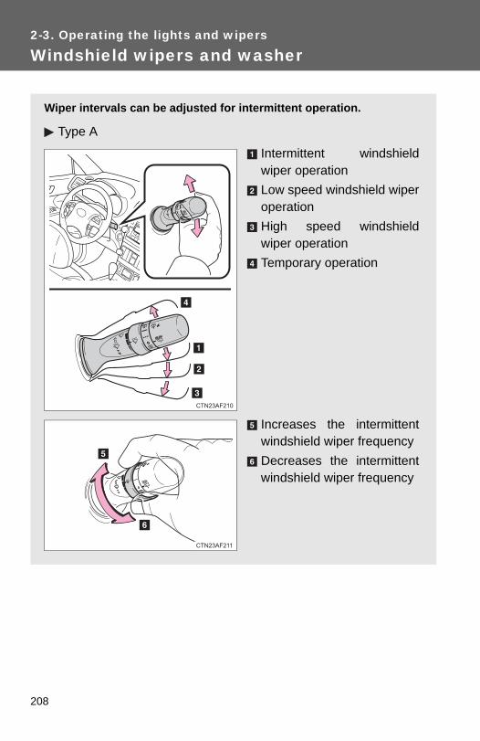
2-3. Operating the lights and wipers
Windshield wipers and washer
Wiper intervals can be adjusted for intermittent operation.
Type A
Intermittent windshieldwiper operationLow speed windshield wiperoperationHigh speed windshieldwiper operationTemporary operation
Increases the intermittentwindshield wiper frequencyDecreases the intermittentwindshield wiper frequency
208

2-3. Operating the lights and wipers
2
When driving
Type B
Intermittent windshieldwiper operationLow speed windshield wiperoperationHigh speed windshieldwiper operationTemporary operation
Increases the intermittentwindshield wiper frequencyDecreases the intermittentwindshield wiper frequency
209

2-3. Operating the lights and wipers
■The windshield wipers and washer can be operated whenVehicles without smart key system
The engine switch is in the “ON” position.
Vehicles with smart key system The “ENGINE START STOP” switch is in IGNITION ON mode.
■ If no windshield washer fluid spraysCheck that the washer nozzles are not blocked and if there is washer fluid inthe windshield washer fluid reservoir.
■ Wash/wipe operationWipers operate automatically.
210

2-3. Operating the lights and wipers
2
When driving
NOTICE
■When the windshield is dryDo not use the wipers, as they may damage the windshield.
■When there is no washer fluid spray from the nozzleDamage to the washer fluid pump may be caused if the lever is pulledtoward you and held continually.
■When a nozzle is blockedDo not try to clear it with a pin or other object. The nozzle will be damaged.
211

2-3. Operating the lights and wipers
Rear window wiper and washer
Type A
Intermittent window wiperoperationNormal window wiper oper-ationWasher/wiper dual opera-tionWasher/wiper dual opera-tion
212
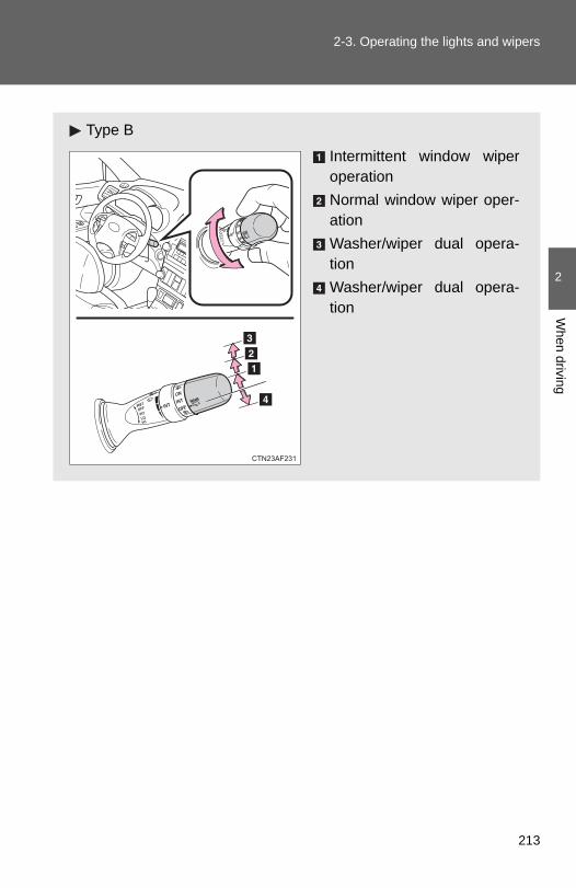
2-3. Operating the lights and wipers
2
When driving
Type B
Intermittent window wiperoperationNormal window wiper oper-ationWasher/wiper dual opera-tionWasher/wiper dual opera-tion
213

2-3. Operating the lights and wipers
■The rear window wiper and washer can be operated whenVehicles without smart key system
The engine switch is in the “ON” position.
Vehicles with smart key system The “ENGINE START STOP” switch is in IGNITION ON mode.
NOTICE
■When the rear window is dryDo not use the wipers, as they may damage the rear window.
214

2-4. Using other driving systems∗
2
When driving
Cruise control
Use the cruise control to maintain a set speed without depressingthe accelerator pedal.
IndicatorCruise control switch
■ Setting the vehicle speedPress the “ON-OFF” button toactivate the cruise control.
Cruise control indicator willcome on.
Press the button again todeactivate the cruise control.
Accelerate or decelerate thevehicle to the desired speed,and push the lever down to setthe speed.
The vehicle speed at themoment the lever is releasedbecomes the set speed.
STEP 1
STEP 2
∗: If equipped
215

2-4. Using other driving systems
■ Adjusting the set speedTo change the set speed, operate the lever until the desired setspeed is obtained.
Increases the speedDecreases the speed
Fine adjustment: Momentarilymove the lever in the desireddirection.
Large adjustment: Hold thelever in the desired direction.
The set speed will be increased or decreased as follows:
Fine adjustment: By approximately 1 mph (1.6 km/h) each time thelever is operated.
Large adjustment: The set speed can be increased or decreased con-tinually until the lever is released.
■ Canceling and resuming the constant speed controlPulling the lever toward youcancels the constant speedcontrol.
The speed setting is also can-celed when the brakes areapplied.
Pushing the lever upresumes the constantspeed control.
Resuming is available whenthe vehicle speed is morethan approximately 25 mph(40 km/h).
216
2-4. Using other driving systems
2
When driving
■Cruise control can be set when●The shift lever is in the D or range “4” or higher of S has been selected.
●Vehicle speed is above approximately 25 mph (40 km/h).
■Accelerating after setting the vehicle speed●The vehicle can be accelerated normally. After acceleration, the set
speed resumes.
●Even without cancelling the cruise control, the set speed can beincreased by first accelerating the vehicle to the desired speed and thenpushing the lever down to set the new speed.
■Automatic cruise control cancelationCruise control will stop maintaining the vehicle speed in any of the followingsituations.
●Actual vehicle speed falls more than approximately 10 mph (16 km/h)below the preset vehicle speed.At this time, the memorized set speed is not retained.
●Actual vehicle speed is below approximately 25 mph (40 km/h).
●Enhanced VSC is activated.
■ If the cruise control indicator light flashesPress the “ON-OFF” button once to deactivate the system, and then pressthe button again to reactivate the system.If the cruise control speed cannot be set or if the cruise control cancelsimmediately after being activated, there may be a malfunction in the cruisecontrol system. Have the vehicle inspected by your Toyota dealer.
217
2-4. Using other driving systems
CAUTION
■To avoid operating the cruise control by mistakeSwitch the cruise control off using the “ON-OFF” button when not in use.
■Situations unsuitable for cruise controlDo not use cruise control in any of the following situations.Doing so may result in loss of control and could cause an accident resultingin death or serious injury.
● In heavy traffic
●On roads with sharp bends
●On winding roads
●On slippery roads, such as those covered with rain, ice or snow
●On steep hillsVehicle speed may exceed the set speed when driving down a steep hill.
●When your vehicle is towing a trailer or during emergency towing
218

2
When driving
2-4. Using other driving systems
Rear view monitor system (vehicles with multi-information display)
Vehicles with navigation systemRefer to the “Navigation System Owner's Manual”.
Vehicles without navigation systemThe rear view monitor system assists the driver by displaying animage of the area behind the vehicle. The image is displayed inreverse on the screen. This reversed image is a similar image to theone on the inside rear view mirror.
The rear view image is dis-played when the shift lever isin the R position.
If the shift lever is shifted out ofR, the screen returns to theprevious one.
219

2-4. Using other driving systems
■Displayed area
■Rear view monitor system camera
The area covered by the camera is lim-ited. Objects that are close to eithercorner of the bumper or under thebumper cannot be seen on the screen.
The area displayed on the screen mayvary according to vehicle orientation orroad conditions.
Corners of bumper
In the following cases, it may becomedifficult to see the images on thescreen, even when the system is func-tioning correctly.
●The vehicle is in a dark area, suchas at night.
●The temperature near the lens isextremely high or low.
●Water droplets are on the cameralens or humidity is high, such aswhen it rains.
●Foreign matter, such as snow ormud, adheres to the camera lens.
●When the camera has scratches ordirt on it.
●The sun or headlights are shiningdirectly into the camera lens.
220

2-4. Using other driving systems
2
When driving
■Smear effect
■Flicker effectWhen the camera is used under fluorescent light, sodium lights, or mercurylights etc., the lights and the illuminated areas may appear to flicker.
■Setting the rear view monitor system display→P. 197
CAUTION
■When using the rear view monitor system, observe the following pre-cautions to avoid an accident that could result in death or serious inju-ries.●Never depend solely on the monitor system when reversing.
●Always check visually and with the mirrors to confirm your intended path isclear.
●Use your own eyes to confirm the vehicle’s surroundings, as the displayedimage may become faint or dark, and moving images will be distorted, ornot entirely visible when the outside temperature is low. When backing up,be sure to check behind and all around the vehicle visually and with themirrors before proceeding.
●Depicted distances between objects and flat surfaces differ from actualdistances.
●Do not use the system if the back door is open.
If a bright light, such as sunlightreflected off the vehicle body, is pickedup by the camera, a smear effect* char-acteristic to the camera may occur.
*: Smear effect: A phenomenon thatoccurs when a bright light is pickedup by the camera; when transmittedby the camera, the light sourceappears to have a vertical streakabove and below it.
221

2-4. Using other driving systems
NOTICE
■Conditions which may affect the rear view monitor system● If the back of the vehicle has been hit, the camera’s position and mounting
angle may have changed. Have the vehicle inspected by your Toyotadealer.
●Rapid temperature changes, such as when hot water is poured on thevehicle in cold weather, may cause the system to function abnormally.
● If the camera lens is dirty, it cannot transmit a clear image. Rinse withwater and wipe with a soft cloth. If extremely dirty, wash with a mildcleanser and rinse.
●The displayed image may be darker and moving images may be slightlydistorted when the system is cold.
■Camera precautions●As the camera has a water proof construction, do not detach, disassemble
or modify it. This may cause incorrect operation.
●Do not subject the camera to a strong impact.
● If the camera lens becomes dirty, it cannot transmit a clear image. If waterdroplets, snow, or mud adhere to the lens, rinse with water and wipe with asoft cloth. If the lens is extremely dirty, wash it with a mild cleanser andrinse. Do not rub hard.
●Do not allow organic solvent, car wax, window cleaner or glass coat toadhere to the camera. If this happens, wipe it off as soon as possible.
●Do not strongly rub the camera lens. If the camera lens is scratched, itcannot transmit a clear image.
●When washing the vehicle, do not apply intensive bursts of water to thecamera or camera area. Doing so may result in the camera malfunction-ing.
●When replacing tires, please consult your Toyota dealer. If you replace thetires, the area displayed on the screen may change.
222

2
When driving
2-4. Using other driving systems
Driving assist systems
To help enhance driving safety and performance, the following sys-tems operate automatically in response to various driving situations.Be aware, however, that these systems are supplementary andshould not be relied upon too heavily when operating the vehicle.
■ ABS (Anti-lock Brake System)Helps to prevent wheel lock when the brakes are applied suddenly, or ifthe brakes are applied while driving on a slippery road surface.
■ Brake assistGenerates an increased level of braking force after the brake pedal isdepressed when the system detects a panic stop situation.
■ Enhanced VSC (Enhanced Vehicle Stability Control)Provides cooperative control of the ABS, TRAC, VSC and EPS.Helps to maintain directional stability when swerving on slippery roadsurfaces by controlling steering performance.
■ TRAC (Traction Control)Helps to maintain drive power and prevent the front wheels (2WD mod-els) or four wheels (4WD models) from spinning when starting the vehi-cle or accelerating on slippery roads.
■ Hill-start assist control→P. 228
■ Downhill assist control system (4WD models only)→P. 230
■ EPS (Electric Power Steering)Employs an electric motor to reduce the amount of effort needed to turnthe steering wheel.
223

2-4. Using other driving systems
When the Enhanced VSC/TRAC systems are operating
If the vehicle is in danger of slip-ping, rolling backwards whenstarting on an incline, or the frontwheels (2WD models) or fourwheels (4WD models) spin, theindicator flashes to indicate thatthe Enhanced VSC/TRAC sys-tems have been engaged.
To disable TRAC and/or Enhanced VSC
If the vehicle gets stuck in fresh snow or mud, TRAC and EnhancedVSC may reduce power from the engine to the wheels. You mayneed to turn the system off to enable you to rock the vehicle in orderto free it.
■ Turning off TRACQuickly push and release thebutton to turn off TRAC.
The “TRAC OFF” indicator lightshould come on.
Push the button again to turn thesystem back on.
224

2-4. Using other driving systems
2
When driving
■ Turning off TRAC and Enhanced VSCPush and hold the button whilethe vehicle is stopped to turn offTRAC and Enhanced VSC.
The “TRAC OFF” and EnhancedVSC off indicator light shouldcome on.
Push the button again to turn thesystem back on.
■When the “TRAC OFF” indicator light comes on even if the EnhancedVSC/TRAC off switch has not been pressedTRAC, hill-start assist control and downhill assist control cannot be oper-ated. Contact your Toyota dealer.
■Automatic reactivation of TRAC and Enhanced VSCVehicles without smart key systemTurning the engine switch OFF after turning off the TRAC and EnhancedVSC systems will automatically re-enable them.
Vehicles with smart key systemTurning the “ENGINE START STOP” switch OFF after turning off theTRAC and Enhanced VSC systems will automatically re-enable them.
■Automatic TRAC reactivationIf only the TRAC system is turned off, the TRAC system will turn on whenvehicle speed increases.
■Automatic TRAC and Enhanced VSC reactivationIf the TRAC and Enhanced VSC systems are turned off, the systems will notturn on even when vehicle speed increases.
225

2-4. Using other driving systems
■Sounds and vibrations caused by the ABS, TRAC, Enhanced VSC andbrake assist●A sound may be heard from the engine compartment when the engine is
started or just after the vehicle begins to move. This sound does not indi-cate that a malfunction has occurred in any of these systems.
●Any of the following conditions may occur when the above systems areoperating. None of these indicates that a malfunction has occurred.
• Vibrations may be felt through the vehicle body and steering.• A motor sound may be heard after the vehicle comes to a stop.• The brake pedal may pulsate slightly when the ABS is activated.• The brake pedal may move down slightly after the ABS is activated.
■EPS operation soundWhen the steering wheel operates, a motor sound (whirring sound) may beheard. This does not indicate a malfunction.
■Reduced effectiveness of EPSThe effectiveness of EPS is reduced to prevent the system from overheatingwhen there is frequent steering input over an extended period of time. Thesteering wheel may feel heavy as a result. Should this occur, refrain fromexcessive steering input or stop the vehicle and turn the engine off. The sys-tem should return to normal within 10 minutes.
■ If the slip indicator comes on...It may indicate a malfunction in the Enhanced VSC and TRAC. Contact yourToyota dealer.
CAUTION
■The ABS does not operate effectively when●Tires with inadequate gripping ability are used (such as excessively worn
tires on a snow covered road).
●The vehicle hydroplanes while driving at high speed on wet or slick road.
226

2-4. Using other driving systems
2
When driving
CAUTION
■Stopping distance when the ABS is operating may exceed that of nor-mal conditionsThe ABS is not designed to shorten the vehicle's stopping distance. Alwaysmaintain a safe distance from the vehicle in front of you in the following situ-ations.
●When driving on dirt, gravel or snow-covered roads
●When driving with tire chains
●When driving over bumps in the road
●When driving over roads with potholes or uneven roads
■TRAC may not operate effectively whenDirectional control and power may not be achievable while driving on slip-pery road surfaces even if the TRAC system is operating.Do not drive the vehicle in conditions where stability and power may be lost.
■When the Enhanced VSC is activatedThe slip indicator light flashes. Always drive carefully. Reckless driving maycause an accident. Exercise particular care when the indicator light flashes.
■When TRAC and Enhanced VSC are offBe especially careful and drive at a speed appropriate to the road condi-tions. As these are systems to help ensure vehicle stability and driving force,do not turn off TRAC and Enhanced VSC unless necessary.
■Replacing tiresMake sure that all tires are of the same size, brand, tread pattern and totalload capacity. In addition, make sure that the tires are inflated to the appro-priate tire pressure level.
The ABS and Enhanced VSC systems will not function correctly if differenttires are fitted on the vehicle.
Contact your Toyota dealer for further information when replacing tires orwheels.
■Handling of tires and suspensionUsing tires with any kind of problem or modifying the suspension will affectthe driving assist systems, and may cause the system to malfunction.
227

2-4. Using other driving systems
Hill-start assist control
■Hill-start assist control operating conditionsThe system operates in the following situations:
• The shift lever is in a position other than P.• The parking brake is not applied.• The accelerator pedal is not depressed.
■Hill-start assist control●While hill-start assist control is operating, the brakes remain automati-
cally applied after the driver releases the brake pedal. The stop lights andthe high mounted stoplight turn on.
●Hill-start assist control operates for about 2 seconds after the brake pedalis released.
● If the slip indicator does not flash and the buzzer does not sound whenthe brake pedal is further depressed, slightly reduce the pressure on thebrake pedal (do not allow the vehicle to roll backward) and then firmlydepress it again. If the system still does not operate, check that the oper-ating conditions explained above have been met.
Hill-start assist control helps to prevent the vehicle from rollingbackwards when starting on an incline or slippery slope.
To engage hill-start assist con-trol, further depress the brakepedal when the vehicle isstopped completely.
A buzzer will sound once toindicate the system is acti-vated. The slip indicator willalso start flashing.
228

2-4. Using other driving systems
2
When driving
■Hill-start assist control buzzer●When hill-start assist control is activated, the buzzer will sound once.
● In the following situations, hill-start assist control will be canceled and thebuzzer will sound twice.
• No attempt is made to drive the vehicle within approximately 2 secondsof releasing the brake pedal.
• The shift lever is moved to P.• The parking brake is applied.• The brake pedal is depressed again.• The brake pedal has been depressed for more than approximately 3
minutes.
■ If the slip indicator comes on...It may indicate a malfunction in the system. Contact your Toyota dealer.
CAUTION
■Hill-start assist control●Do not overly rely on hill-start assist control. Hill-start assist control may
not operate effectively on extremely steep inclines or roads covered in ice.
●Unlike the parking brake, hill-start assist control is not intended to hold thevehicle stationary for an extended period of time. Do not attempt to usehill-start assist control to hold the vehicle on an incline for an extendedperiod of time, as doing so may lead to an accident.
229

2-4. Using other driving systems
Downhill assist control system (4WD models)
While the downhill assist control system is operating
The slip indicator will flash toindicate that the downhill assistcontrol system is operating, andthe stop lights and high mountedstoplight will turn on.
With the downhill assist control system, the vehicle is able todescend a steep hill, maintaining a constant low speed of about 3mph (5 km/h) without brake pedal operation.
■ Activating the downhill assist control systemPress the “DAC” switch.
The downhill assist control sys-tem indicator will come on toindicate that the downhill assistcontrol system is activated.
Pressing the switch again turnsthe system off.
230

2-4. Using other driving systems
2
When driving
■Conditions in which the downhill assist control system does not oper-ate● In the following situations, the downhill assist control system indicator
flashes and the downhill assist control system does not operate or willstop operating:
• The shift lever is not in “1” range of S mode or R.• The vehicle speed is higher than 15 mph (25 km/h).
● If the accelerator or brake pedal is depressed, the downhill assist controlsystem will stop operating with the downhill assist control system indica-tor still on.
■ If the “DAC” switch is turned off during operation of the downhill assistcontrol systemThe downhill assist control system gradually ceases operation. The downhillassist control system indicator will flash during the canceling operation, andthen go off when the system is fully off.
■Downhill assist control system operation sound●A sound may be heard from the engine compartment during operation of
the downhill assist control system. This sound does not indicate a mal-function.
● If the accelerator or brake pedal is depressed during operation of thedownhill assist control system, a sound caused by the release of systemoperation may be heard, or you may feel the brake pedal push-back. Thisdoes not indicate a malfunction.
■When the downhill assist control system operates continuouslyThe brake actuator may overheat. In that case, the downhill assist controlsystem will stop operating, a buzzer will sound and the downhill assist con-trol system indicator will start flashing. Refrain from using the system untilthe downhill assist control system indicator stays on. (There is no problemwith continuing to drive normally.)
■ If the slip indicator comes on...It may indicate a malfunction in the system. Contact your Toyota dealer.
231

2-4. Using other driving systems
CAUTION
■Conditions which may affect the downhill assist control system opera-tion●Do not rely too heavily on the downhill assist control system. On extremely
steep inclines, icy surfaces or muddy roads, the vehicle may slip and thesystem may not be able to maintain the constant low vehicle speed ofabout 3 mph (5 km/h), leading to an accident causing death or seriousinjury.
●Do not shift the shift lever to R while driving forward, or to D while drivingbackward. Doing so may cause the wheels to lock up, leading to an acci-dent causing death or serious injury. In addition, excessive stress will beapplied to the automatic transmission, possibly resulting in damage.
232
2-5. Driving information
2
When driving
Off-road precautions
Off-road vehicle feature
● Specific design characteristics give it a higher center of gravitythan ordinary passenger cars. This vehicle design feature causesthis type of vehicle to be more likely to rollover. And, utility vehicleshave a significantly higher rollover rate than other types of vehi-cles.
● An advantage of the higher ground clearance is a better view of theroad allowing you to anticipate problems.
● It is not designed for cornering at the same speeds as an ordinarypassenger car. Sharp turns at excessive speeds may cause roll-over.
This vehicle belongs to the utility vehicle class, which has higherground clearance and narrower tread in relation to the height of itscenter of gravity to make it capable of performing in a wide varietyof off-road applications.
233

2-5. Driving information
CAUTION
■Off-road vehicle precautionsAlways observe the following precautions to minimize the risk of serious per-sonal injury or damage to your vehicle:
● In a rollover crash, an unbelted person is significantly more likely to diethan a person wearing a seat belt. Therefore, the driver and all passengersshould fasten their seat belts whenever the vehicle is moving.
●Avoid sharp turns or abrupt maneuvers, if at all possible. Failure to operate this vehicle correctly may result in loss of control orvehicle rollover causing death or serious injury.
●Loading cargo on the roof luggage carrier will make the center of the vehi-cle gravity higher. Avoid high speeds, sudden starts, sharp turns, suddenbraking or abrupt maneuvers, otherwise it may result in loss of control orvehicle rollover due to failure to operate this vehicle correctly.
●Always slow down in gusty crosswinds. Because of its profile and highercenter of gravity, your vehicle is more sensitive to side winds than an ordi-nary passenger car. Slowing down will allow you to have better control.
●Do not drive horizontally across steep slopes. Driving straight up orstraight down is preferred. Your vehicle (or any similar off-road vehicle)can tip over sideways much more easily than forward or backward.
234

2-5. Driving information
2
When driving
Off-road driving
When driving your vehicle off-road, please observe the following pre-cautions to ensure your driving enjoyment and to help prevent theclosure of areas to off-road vehicles.
● Drive your vehicle only in areas where off-road vehicles are permit-ted to travel.
● Respect private property. Get owner’s permission before enteringprivate property.
● Do not enter areas that are closed. Honor gates, barriers and signsthat restrict travel.
● Stay on established roads. When conditions are wet, driving tech-niques should be changed or travel delayed to prevent damage toroads.
■Additional information for off-road drivingFor owners in U.S. mainland, Hawaii and Puerto Rico:
To obtain additional information pertaining to driving your vehicle off-road,consult the following organizations.
●State and Local Parks and Recreation Departments
●State Motor Vehicle Bureau
●Recreational Vehicle Clubs
●U.S. Forest Service and Bureau of Land Management
235

2-5. Driving information
CAUTION
■Off-road driving precautionsAlways observe the following precautions to minimize the risk of serious per-sonal injury or damage to your vehicle:
●Drive carefully when off the road. Do not take unnecessary risks by drivingin dangerous places.
●Do not grip the steering wheel spokes when driving off-road. A bad bumpcould jerk the wheel and injure your hands. Keep both hands and espe-cially your thumbs on the outside of the rim.
●Always check your brakes for effectiveness immediately after driving insand, mud, water or snow.
●After driving through tall grass, mud, rock, sand, rivers, etc., check thatthere is no grass, bush, paper, rags, stone, sand, etc. adhering or trappedon the underbody. Clear off any such matter from the underbody. If thevehicle is used with these materials trapped or adhering to the underbody,a breakdown or fire could occur.
●When driving off-road or in rugged terrain, do not drive at excessivespeeds, jump, make sharp turns, strike objects, etc. This may cause lossof control or vehicle rollover causing death or serious injury. You are alsorisking expensive damage to your vehicle’s suspension and chassis.
NOTICE
■To prevent water damageTake all necessary safety measures to ensure that water damage to theengine or other components does not occur.
●Water entering the engine air intake will cause severe engine damage.
●Water entering the automatic transmission will cause deterioration in shiftquality, locking up of your transmission accompanied by vibration, and ulti-mately damage.
●Water can wash the grease from wheel bearings, causing rusting and pre-mature failure, and may also enter the differentials, transmission andtransfer case, reducing the gear oil’s lubricating qualities.
236

2-5. Driving information
2
When driving
NOTICE
■When you drive through waterIf driving through water, such as when crossing shallow streams, first checkthe depth of the water and the bottom of the river bed for firmness. Driveslowly and avoid deep water.
■ Inspection after off-road driving●Sand and mud that has accumulated in brake drums and around brake
discs may affect braking efficiency and may damage brake system compo-nents.
●Always perform a maintenance inspection after each day of off-road driv-ing that has taken you through rough terrain, sand, mud, or water. Forscheduled maintenance information, refer to the “Scheduled MaintenanceGuide” or “Owner’s Manual Supplement”.
237

2-5. Driving information
Cargo and luggage
Capacity and distribution
Cargo capacity depends on the total weight of the occupants.
(Cargo capacity) = (Total load capacity) - (Total weight of occupants)
Steps for Determining Correct Load Limit⎯(1)Locate the statement “The combined weight of occupants and
cargo should never exceed XXX kg or XXX lbs.” on your vehicle'splacard.
(2)Determine the combined weight of the driver and passengers thatwill be riding in your vehicle.
(3)Subtract the combined weight of the driver and passengers fromXXX kg or XXX lbs.
(4)The resulting figure equals the available amount of cargo and lug-gage load capacity. For example, if the “XXX” amount equals 1400 lbs. and there willbe five 150 lb passengers in your vehicle, the amount of availablecargo and luggage load capacity is 650 lbs. (1400 - 750 (5 × 150) =650 lbs.)
(5)Determine the combined weight of luggage and cargo beingloaded on the vehicle. That weight may not safely exceed the avail-able cargo and luggage load capacity calculated in Step 4.
Take notice of the following information about storage precau-tions, cargo capacity and load.
● Stow cargo and luggage in the luggage compartment wheneverpossible. Be sure all items are secured in place.
● Be careful to keep the vehicle level. Placing the weight as far for-ward as possible helps maintain vehicle balance.
● For better fuel economy, do not carry unnecessary weight.
238
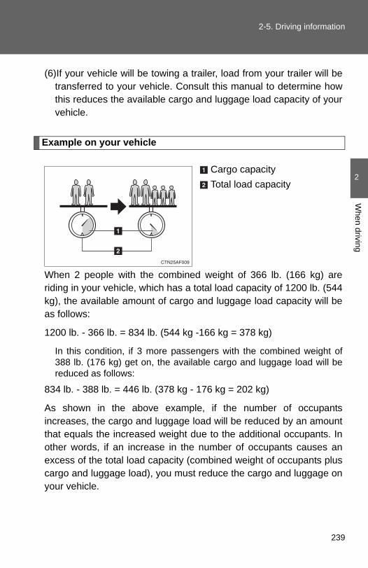
2-5. Driving information
2
When driving
(6)If your vehicle will be towing a trailer, load from your trailer will betransferred to your vehicle. Consult this manual to determine howthis reduces the available cargo and luggage load capacity of yourvehicle.
Example on your vehicle
Cargo capacityTotal load capacity
When 2 people with the combined weight of 366 lb. (166 kg) areriding in your vehicle, which has a total load capacity of 1200 lb. (544kg), the available amount of cargo and luggage load capacity will beas follows:
1200 lb. - 366 lb. = 834 lb. (544 kg -166 kg = 378 kg)
In this condition, if 3 more passengers with the combined weight of388 lb. (176 kg) get on, the available cargo and luggage load will bereduced as follows:
834 lb. - 388 lb. = 446 lb. (378 kg - 176 kg = 202 kg)
As shown in the above example, if the number of occupantsincreases, the cargo and luggage load will be reduced by an amountthat equals the increased weight due to the additional occupants. Inother words, if an increase in the number of occupants causes anexcess of the total load capacity (combined weight of occupants pluscargo and luggage load), you must reduce the cargo and luggage onyour vehicle.
239

2-5. Driving information
CAUTION
■Things that must not be carried in the luggage compartmentThe following things may cause a fire if loaded in the luggage compart-ment.●Receptacles containing gasoline●Aerosol cans
■Storage precautionsObserve the following precautions.Failing to do so may result in death or serious injury.
●Do not place cargo or luggage in or on the following locations as theitem may get under the brake or accelerator pedal and prevent thepedals from being depressed properly, block the driver’s vision, or hitthe driver or passengers, causing an accident.• Driver’s feet• Front passenger or rear seats (when stacking items)• Luggage cover• Instrument panel• Dashboard
●Secure all items in the occupant compartment, as they may shift andinjure someone during sudden braking, sudden swerving or an acci-dent.
●When you fold down the rear seats, long items should not be placeddirectly behind the front seats.
●Never allow anyone to ride in the luggage compartment. It is notdesigned for passengers. They should ride in their seats with their seatbelts properly fastened. Otherwise, they are much more likely to sufferserious bodily injury, in the event of sudden braking, sudden swervingor an accident.
240
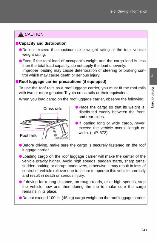
2-5. Driving information
2
When driving
CAUTION
■Capacity and distribution●Do not exceed the maximum axle weight rating or the total vehicle
weight rating. ●Even if the total load of occupant's weight and the cargo load is less
than the total load capacity, do not apply the load unevenly. Improper loading may cause deterioration of steering or braking con-trol which may cause death or serious injury.
■Roof luggage carrier precautions (if equipped)To use the roof rails as a roof luggage carrier, you must fit the roof railswith two or more genuine Toyota cross rails or their equivalent.When you load cargo on the roof luggage carrier, observe the following:
●Before driving, make sure the cargo is securely fastened on the roofluggage carrier.
●Loading cargo on the roof luggage carrier will make the center of thevehicle gravity higher. Avoid high speeds, sudden starts, sharp turns,sudden braking or abrupt maneuvers, otherwise it may result in loss ofcontrol or vehicle rollover due to failure to operate this vehicle correctlyand result in death or serious injury.
● If driving for a long distance, on rough roads, or at high speeds, stopthe vehicle now and then during the trip to make sure the cargoremains in its place.
●Do not exceed 100 lb. (45 kg) cargo weight on the roof luggage carrier.
●Place the cargo so that its weight isdistributed evenly between the frontand rear axles.
● If loading long or wide cargo, neverexceed the vehicle overall length orwidth. (→P. 572)
Cross rails
Roof rails
241

2-5. Driving information
Vehicle load limits
■Total load capacity and seating capacityThese details are also described on the tire and loading informationlabel. (→P. 487)
CAUTION
■Overloading the vehicleDo not overload the vehicle.It may not only cause damage to the tires, but also degrade steering andbraking ability, resulting in an accident.
Vehicle load limits include total load capacity, seating capacity,trailer weight rating and cargo capacity.
■ Total load capacity: 1200 lb. (544 kg) Total load capacity means the combined weight of occupants, cargoand luggage.
■ Seating capacity: 7 occupants (Front 2, Rear 5)Seating capacity means the maximum number of occupants whoseestimated average weight is 150 lb. (68 kg) per person.
■ Trailer Weight Rating2.7 L 4-cylinder (1AR-FE) engine
Without towing package: 1500 lb. (680 kg)With towing package: 3500 lb. (1500 kg)
3.5 L V6 (2GR-FE) engineWithout towing package: 2000 lb. (900 kg) With towing package: 5000 lb. (2000 kg)Trailer weight rating means the maximum gross trailer weight(trailer weight plus its cargo weight) that your vehicle is able to tow.
■ Cargo capacityCargo capacity may increase or decrease depending on the weightand the number of occupants.
242

2
When driving
2-5. Driving information
Winter driving tips
Carry out the necessary preparations and inspections before drivingthe vehicle in winter. Always drive the vehicle in a manner appropri-ate to the prevailing weather conditions.
■ Pre-winter preparations● Use fluids that are appropriate to the prevailing outside tem-
peratures.
• Engine oil• Engine coolant• Washer fluid
● Have a service technician inspect the level and specific grav-ity of battery electrolyte.
● Have the vehicle fitted with four snow tires or purchase a setof tire chains for the front tires.
Ensure that all tires are the same size and brand, and that chainsmatch the size of the tires.
■ Before driving the vehicleObserve the following according to the driving conditions.
● Do not try to forcibly open a window or move a wiper that isfrozen. Pour warm water over the frozen area to melt the ice.Wipe away the water immediately to prevent it from freezing.
● To ensure proper operation of the climate control system fan,remove any snow that has accumulated on the air inlet ventsin front of the windshield.
● Remove any ice that has accumulated on the vehicle chassis.
● Periodically check for and remove any excess ice or snowthat may have accumulated in the wheel well or on thebrakes.
243

2-5. Driving information
Selecting tire chains
Use the correct tire chain size when mounting the snow chains. Chain size is regulated for each tire size.
Side chain 0.12 in. (3 mm) in diameter 0.39 in. (10 mm) in width 1.18 in. (30 mm) in length Cross chain 0.16 in. (4 mm) in diameter 0.55 in. (14 mm) in width 0.98 in. (25 mm) in length
Regulations on the use of snow chains
● Regulations regarding the use of tire chains vary according to loca-tion and type of road. Always check local regulations before install-ing chains.
● Install the chains on the front tires.
● Retighten the chains after driving 1/4 - 1/2 mile (0.5 - 1.0 km).
■ When driving the vehicleAccelerate the vehicle slowly and drive at a reduced speed suit-able to road conditions.
■ When parking the vehiclePark the vehicle and move the shift lever to P without setting theparking brake. The parking brake may freeze up, preventing itfrom being released. If necessary, brake the wheels to preventinadvertent sliding or creeping.
244

2-5. Driving information
2
When driving
■Tire chainsObserve the following precautions when installing and removing chains.
● Install and remove tire chains in a safe location.
● Install tire chains on the front tires.
● Install tire chains following the instructions provided in the accompanyingmanual.
CAUTION
■Driving with snow tiresObserve the following precautions to reduce the risk of accidents.Failing to do so may result in a loss of vehicle control and cause death orserious injury.
●Use tires of the specified size.
●Maintain the recommended level of air pressure.
●Do not drive in excess of 75 mph (120 km/h), regardless of the type ofsnow tires being used.
●Snow tires should be installed on all wheels.
■Driving with tire chainsObserve the following precautions to reduce the risk of accidents.Failing to do so may result in the vehicle being unable to be driven safely,and may cause death or serious injury.
●Do not drive in excess of the speed limit specified for the tire chains beingused or 30 mph (50 km/h), whichever is lower.
●Avoid driving on bumpy road surfaces or over potholes.
●Avoid sudden turns and braking.
●Slow down sufficiently before entering a curve to ensure that vehicle con-trol is maintained.
245

2-5. Driving information
NOTICE
■Repairing or replacing snow tiresRequest repairs of and obtain replacement snow tires from Toyota dealers orlegitimate tire retailers.This is because the removal and attachment of snow tires affects the opera-tion of the tire pressure warning valves and transmitters.
■Fitting tire chainsThe tire pressure warning valves and transmitters may not function correctlywhen tire chains are fitted.
246

2
When driving
2-5. Driving information
Trailer towing
Towing related terms
■ GCWR (Gross Combination Weight Rating)The maximum allowable grosscombination weight. The grosscombination weight is the sum ofthe total vehicle weight (includingthe occupants, cargo and anyoptional equipment installed onthe vehicle) and the weight of thetrailer being towed (including thecargo in the trailer).
Your vehicle is designed primarily as a passenger-and-load-carryingvehicle. Towing a trailer can have an adverse impact on handling,performance, braking, durability, and fuel consumption. For yoursafety and the safety of others, you must not overload your vehicleor trailer. You must also ensure that you are using appropriate tow-ing equipment, that the towing equipment has been installed cor-rectly and used properly, and that you employ the requisite drivinghabits.
Vehicle-trailer stability and braking performance are affected bytrailer stability, brake performance and setting, trailer brakes, thehitch and hitch systems (if equipped).
To tow a trailer safely, use extreme care and drive the vehicle inaccordance with your trailer’s characteristics and operating condi-tions.
Toyota warranties do not apply to damage or malfunction caused bytowing a trailer for commercial purposes.
Contact your Toyota dealer for further information about additionalrequirements such as towing kits, etc.
247
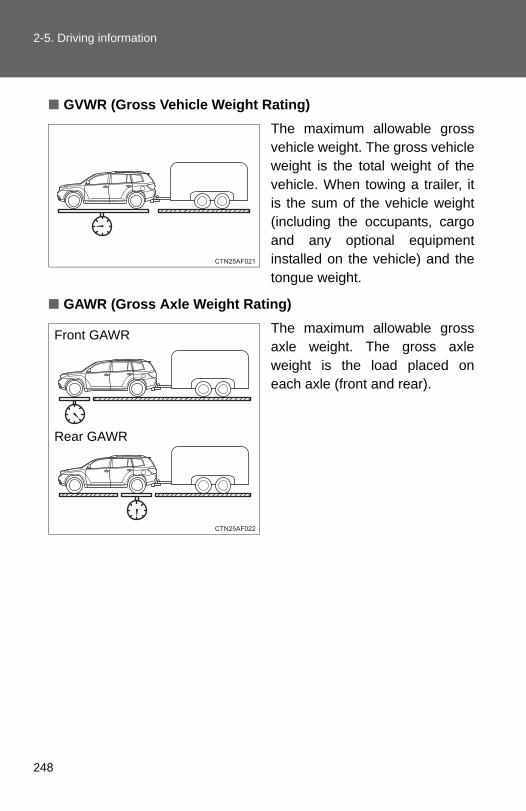
2-5. Driving information
■ GVWR (Gross Vehicle Weight Rating)The maximum allowable grossvehicle weight. The gross vehicleweight is the total weight of thevehicle. When towing a trailer, itis the sum of the vehicle weight(including the occupants, cargoand any optional equipmentinstalled on the vehicle) and thetongue weight.
■ GAWR (Gross Axle Weight Rating)The maximum allowable grossaxle weight. The gross axleweight is the load placed oneach axle (front and rear).
Front GAWR
Rear GAWR
248

2-5. Driving information
2
When driving
■ TWR (Trailer Weight Rating)The maximum allowable grosstrailer weight. The gross trailerweight is the sum of the trailerweight and the weight of thecargo in the trailer.
TWR is calculated assumingbase vehicle with one driver, onefront passenger, towing package(if available), hitch and hitch sys-tems (if required).
Additional optional equipment,passengers and cargo in the vehi-cle will reduce the trailer weightrating so as not to exceedGCWR, GVWR and GAWR.
If the gross trailer weight exceeds3000 lb. (1360 kg), it is recom-mended to use a trailer with 2 ormore axles.
■ Unbraked TWR (Unbraked Trailer Weight Rating)The trailer weight rating for tow-ing a trailer without a trailer ser-vice brake system.
(With brakes)
(Without brakes)
249

2-5. Driving information
■ Tongue WeightThe load placed on the trailerhitch ball. (→P. 252)
Weight limits
● The gross trailer weight must never exceed the TWR described inthe table. (→P. 251)
● The gross combination weight must never exceed the GCWRdescribed in the table. (→P. 251)
● The gross vehicle weight mustnever exceed the GVWR indi-cated on the CertificationLabel.
● The gross axle weight on eachaxle must never exceed theGAWR indicated on the Certi-fication Label.
● If the gross trailer weight is over the unbraked TWR, trailer servicebrakes are required.
● If the gross trailer weight is over 2000 lb. (907 kg), a sway controldevice with sufficient capacity is required.
250
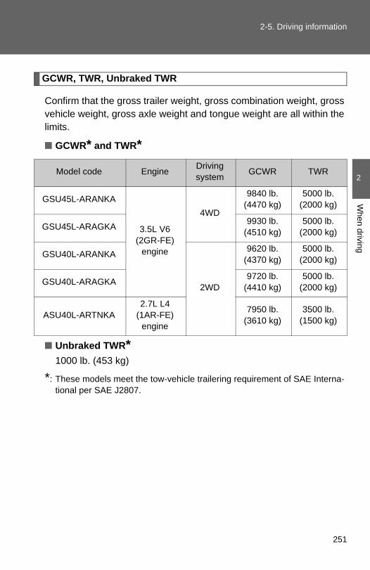
2-5. Driving information
2
When driving
GCWR, TWR, Unbraked TWR
Confirm that the gross trailer weight, gross combination weight, grossvehicle weight, gross axle weight and tongue weight are all within thelimits.
■ GCWR* and TWR*
■ Unbraked TWR*1000 lb. (453 kg)
*: These models meet the tow-vehicle trailering requirement of SAE Interna-tional per SAE J2807.
Model code Engine Driving system GCWR TWR
GSU45L-ARANKA
3.5L V6(2GR-FE)
engine
4WD
9840 lb.(4470 kg)
5000 lb.(2000 kg)
GSU45L-ARAGKA 9930 lb.(4510 kg)
5000 lb.(2000 kg)
GSU40L-ARANKA
2WD
9620 lb.(4370 kg)
5000 lb.(2000 kg)
GSU40L-ARAGKA 9720 lb.(4410 kg)
5000 lb.(2000 kg)
ASU40L-ARTNKA2.7L L4
(1AR-FE)engine
7950 lb.(3610 kg)
3500 lb.(1500 kg)
251

2-5. Driving information
Trailer Tongue Weight
● A recommended tongue weight varies in accordance with the typesof trailers or towing as described below.
● To ensure the recommended values shown below, the trailer mustbe loaded by referring to the following instructions.
• Tongue Weight
The gross trailer weight should be distributed so that the tongueweight is 9% to 11%. (Tongue weight /Gross trailer weight x 100= 9% to 11%)
Gross trailer weightTongue weight
If using a weight distributing hitch when towing, return the frontaxle to the same weight as before the trailer connection.
If front axle weight cannot be measured directly, measure thefront fender height above the front axle before connection.Adjust weight distributing hitch torque until front fender isreturned to the same height as before connection.
The gross trailer weight, gross axle weight and tongue weightcan be measured with platform scales found at a highwayweighing station, building supply company, trucking company,junk yard, etc.
252

2-5. Driving information
2
When driving
Hitch
Trailer hitch assemblies have different weight capacities. Toyota rec-ommends the use of Toyota hitch/bracket for your vehicle. For details,contact your Toyota dealer.
● If you wish to install a trailer hitch, contact your Toyota dealer.
● Use only a hitch that conforms to the gross trailer weight require-ment of your vehicle.
● Follow the directions supplied by the hitch manufacturer.
● Lubricate the hitch ball with a light coating of grease.
● Remove the trailer hitch whenever you are not towing a trailer.After removing the hitch, seal any mounting hole in the vehiclebody to prevent entry of any substances into the vehicle.
Removing hitch cover
Remove the clip.
Grasp the lower edge of the hitchcover and raise the cover.
When reattaching the cover,reverse the steps listed.
STEP 1
STEP 2
253

2-5. Driving information
Selecting trailer ball
Use the correct trailer ball for your application.
Trailer ball load rating
Matches or exceeds the grosstrailer weight rating of the trailer.
Ball diameter
Matches the size of the trailercoupler. Most couplers arestamped with the required trailerball size.
Shank length
Protrudes beyond the bottom ofthe lock washer and nut by atleast 2 threads.
Shank diameter
Matches the ball mount holediameter size.
Trailer class
Typical trailer ball size
IV 2 5/16 in.
II and III 2 in.
I 1 7/8 in.
254

2-5. Driving information
2
When driving
Positions for towing hitch receiver and hitch ball
Weight carrying ball position:48.1 in. (1221 mm)
Connecting trailer lights
Use the wire harness stored inthe rear end under body.
255

2-5. Driving information
Trailer towing tips
Your vehicle will handle differently when towing a trailer. Help to avoidan accident, death or serious injury, keep the following in mind whentowing:
● Speed limits for towing a trailer vary by state or province. Do notexceed the posted towing speed limit.
● Toyota recommends that the vehicle-trailer speed limit is 65 mph(104 km/h) on a flat, straight, dry road. Do not exceed this limit, theposted towing speed limit or the speed limit for your trailer as setforth in your trailer owner’s manual, whichever is lowest. Instabilityof the towing vehicle-trailer combination (trailer sway) increases asspeed increases. Exceeding speed limits may cause loss of con-trol.
● Before starting out, check the trailer lights, tires and the vehicle-trailer connections. Recheck after driving a short distance.
● Practice turning, stopping and reversing with the trailer attached inan area away from traffic until you become accustomed to the feelof the vehicle-trailer combination.
● Reversing with a trailer attached is difficult and requires practice.Grip the bottom of the steering wheel and move your hand to theleft to move the trailer to the left. Move your hand to the right tomove the trailer to the right. (This is generally opposite to reversingwithout a trailer attached.) Avoid sharp or prolonged turning. Havesomeone guide you when reversing to reduce the risk of an acci-dent.
● As stopping distance is increased when towing a trailer, vehicle-to-vehicle distance should be increased. For each 10 mph (16 km/h)of speed, allow at least one vehicle and trailer length.
● Avoid sudden braking as you may skid, resulting in the trailer jack-knifing and a loss of vehicle control. This is especially true on wetor slippery surfaces.
256

2-5. Driving information
2
When driving
● Avoid jerky starts or sudden acceleration.
● Avoid jerky steering and sharp turns, and slow down before mak-ing a turn.
● Note that when making a turn, the trailer wheels will be closer thanthe vehicle wheels to the inside of the turn. Compensate by makinga wider than normal turning radius.
● Slow down before making a turn, in cross winds, on wet or slipperysurfaces, etc.Increasing vehicle speed can destabilize the trailer.
● Take care when passing other vehicles. Passing requires consider-able distance. After passing a vehicle, do not forget the length ofyour trailer, and be sure you have plenty of room before changinglanes.
● To maintain engine braking efficiency and charging system perfor-mance when using engine braking, do not put the transmission inD.
● Instability happens more frequently when descending steep or longdownhill grades. Before descending, slow down and downshift. Donot make sudden downshifts while descending steep or long down-hill grades.
● Avoid holding the brake pedal down too long or applying thebrakes too frequently. This could cause the brakes to overheat andresult in reduced braking efficiency.
● Due to the added load of the trailer, your vehicle’s engine mayoverheat on hot days (at temperatures over 85°F [30°C]) whendriving up a long or steep grade. If the engine coolant temperaturegauge indicates overheating, immediately turn off the air condition-ing (if in use), pull your vehicle off the road and stop in a safe spot.(→P. 564)
257

2-5. Driving information
● Always place wheel blocks under both the vehicle’s and thetrailer’s wheels when parking. Apply the parking brake firmly, andput the transmission in P. Avoid parking on a slope, but if unavoid-able, do so only after performing the following:
Apply the brakes and keep them applied.Have someone place wheel blocks under both the vehicle’sand trailer’s wheels.When the wheel blocks are in place, release the brakes slowlyuntil the blocks absorb the load.Apply the parking brake firmly.Shift into P and turn off the engine.
● When restarting after parking on a slope:
With the transmission in P, start the engine. Be sure to keepthe brake pedal depressed.Shift into a forward gear. If reversing, shift into R.Release the parking brake and also the brake pedal, andslowly pull or back away from the wheel blocks. Stop andapply the brakes.Have someone retrieve the blocks.
STEP 1
STEP 2
STEP 3
STEP 4
STEP 5
STEP 1
STEP 2
STEP 3
STEP 4
258

2-5. Driving information
2
When driving
■Matching trailer ball height to trailer coupler height
■Before towingCheck that the following conditions are met:
●Ensure that your vehicle’s tires are properly inflated. (→P. 584)
●Trailer tires are inflated according to the trailer manufacturer’s recom-mendation.
●All trailer lights work as required by law.
●All lights work each time you connect them.
●The trailer ball is set at the proper height for the coupler on the trailer.
●The vehicle remains level when a loaded or unloaded trailer is hitched.Do not drive if the vehicle is not level, and check for improper tongueweight, overloading, worn suspension, or other possible causes.
●The trailer cargo is securely loaded.
●The rear view mirrors conform to all applicable federal, state/provincial orlocal regulations. If they do not, install rear view mirrors appropriate fortowing purposes.
No matter which class of tow hitchapplies, for a more safe trailer hookup,the trailer ball setup must be the properheight for the coupler on the trailer.
Coupler
Trailer ball
259

2-5. Driving information
■Break-in scheduleIf your vehicle is new or equipped with any new power train components(such as an engine, transmission, differential or wheel bearing), Toyota rec-ommends that you do not tow a trailer until the vehicle has been driven forover 500 miles (800 km).
After the vehicle has been driven for over 500 miles (800 km), you can starttowing. However, for the next 500 miles (800 km), drive the vehicle at aspeed of less than 50 mph (80 km/h) when towing a trailer, and avoid fullthrottle acceleration.
■Maintenance● If you tow a trailer, your vehicle will require more frequent maintenance
due to the additional load. (See “Scheduled Maintenance Guide” or“Owner’s Manual Supplement”.)
●Retighten the fixing bolts of the towing ball and bracket after approxi-mately 600 miles (1000 km) of trailer towing.
260

2-5. Driving information
2
When driving
■ If trailer sway occursOne or more factors (crosswinds, passing vehicles, rough roads, etc.) canadversely affect handling of your vehicle and trailer, causing instability.
● If trailer swaying occurs:
• Firmly grip the steering wheel. Steer straight ahead.Do not try to control trailer swaying by turning the steering wheel.
• Begin releasing the accelerator pedal immediately but very gradually toreduce speed.Do not increase speed. Do not apply vehicle brakes.
If you make no extreme correction with the steering or brakes, your vehicleand trailer should stabilize.
●After the trailer swaying has stopped:
• Stop in a safe place. Get all occupants out of the vehicle.• Check the tires of the vehicle and the trailer.• Check the load in the trailer.
Make sure the load has not shifted.Make sure the tongue weight is appropriate, if possible.
• Check the load in the vehicle.Make sure the vehicle is not overloaded after occupants get in.
If you cannot find any problems, the speed at which trailer swaying occurredis beyond the limit of your particular vehicle-trailer combination.Drive at a lower speed to prevent instability. Remember that swaying of thetowing vehicle-trailer increases as speed increases.
CAUTION
■Trailer towing precautionsTo tow a trailer safely, use extreme care and drive the vehicle in accordancewith the trailer’s characteristics and operating conditions. Failure to do socould cause an accident resulting in death or serious injury. Vehicle stabilityand braking performance are affected by trailer stability, brake setting andperformance, and the hitch. Your vehicle will handle differently when towinga trailer.
261
2-5. Driving information
CAUTION
■To avoid accident or injury●Do not exceed the TWR, unbraked TWR, GCWR, GVWR or GAWR.
● If the gross trailer weight is over 2000 lb. (907 kg), a sway control devicewith sufficient capacity is required.
●Adjust the tongue weight within the appropriate range. Place heavier loadsas close to the trailer axle as possible.
●Do not exceed 65 mph (104 km/h), the posted towing speed limit or thespeed limit for your trailer as set forth in your trailer owner’s manual,whichever is lowest. Slow down sufficiently before making a turn, in crosswinds, on wet or slippery surface, etc. to help avoid an accident. If youexperience a vehicle-trailer instability from reducing a certain speed, slowdown and make sure you keep your vehicle speed under the speed ofwhich you experience the instability.
●Do not make jerky, abrupt or sharp turns.
●Do not apply the brakes suddenly as you may skid, resulting in jackknifingand loss of vehicle control. This is especially true on wet or slippery sur-faces.
●Do not exceed the trailer hitch assembly weight, gross vehicle weight,gross axle weight and trailer tongue weight capacities.
●Do not use cruise control when towing.
●Slow down and downshift before descending steep or long downhillgrades. Do not make sudden downshifts while descending steep or longdownhill grades.
●Vehicle-trailer instability is more likely on steep long downhills. Beforedescending steep or long downhill grades, slow down and downshift. Donot make sudden downshifts when descending steep or long downhillgrades. Avoid holding the brake pedal down too long or applying thebrakes too frequently. This could cause the brakes to overheat and resultin reduced braking efficiency.
262
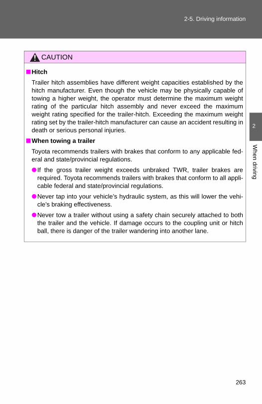
2-5. Driving information
2
When driving
CAUTION
■HitchTrailer hitch assemblies have different weight capacities established by thehitch manufacturer. Even though the vehicle may be physically capable oftowing a higher weight, the operator must determine the maximum weightrating of the particular hitch assembly and never exceed the maximumweight rating specified for the trailer-hitch. Exceeding the maximum weightrating set by the trailer-hitch manufacturer can cause an accident resulting indeath or serious personal injuries.
■When towing a trailerToyota recommends trailers with brakes that conform to any applicable fed-eral and state/provincial regulations.
● If the gross trailer weight exceeds unbraked TWR, trailer brakes arerequired. Toyota recommends trailers with brakes that conform to all appli-cable federal and state/provincial regulations.
●Never tap into your vehicle’s hydraulic system, as this will lower the vehi-cle’s braking effectiveness.
●Never tow a trailer without using a safety chain securely attached to boththe trailer and the vehicle. If damage occurs to the coupling unit or hitchball, there is danger of the trailer wandering into another lane.
263

2-5. Driving information
NOTICE
■When installing a trailer hitchUse only the position recommended by your Toyota dealer. Do not install thetrailer hitch on the bumper; this may cause body damage.
■Safety chainA safety chain must always be used between the towing vehicle and thetrailer. Leave sufficient slack in the chain for turns. The chain should crossunder the trailer tongue to prevent the tongue from dropping to the ground inthe case that it becomes damaged or separated. For the correct safety chaininstallation procedure, ask your Toyota dealer.
■Do not directly splice trailer lightsDo not directly splice trailer lights. Directly splicing trailer lights may damageyour vehicle’s electrical system and cause a malfunction.
264

2
When driving
2-5. Driving information
Dinghy towing
NOTICE
■To avoid serious damage to your vehicleDo not tow your vehicle with 4 wheels on the ground.
Your vehicle is not designed to be dinghy towed (with 4 wheels onthe ground) behind a motor home.
265

3-1. Using the air conditioning system and defogger∗
Front manual air conditioning systemAdjusting the settings
■ Adjusting the temperature settingTurn the temperature control dial clockwise (warm) or counter-clockwise (cool).
If is not pressed, the system will blow ambient temperature air orheated air.
For quick cooling, turn the temperature selector knob to the “MAX A/C”
position. The air conditioning will automatically turn on in (recir-culated air) mode.
Fan speed control dial
Air outlet selection dial
Air conditioning on/off switch
Temperature control dialOutside air or recirculated air mode
Rear air conditioning on/off switch (if equipped)
∗: If equipped
268
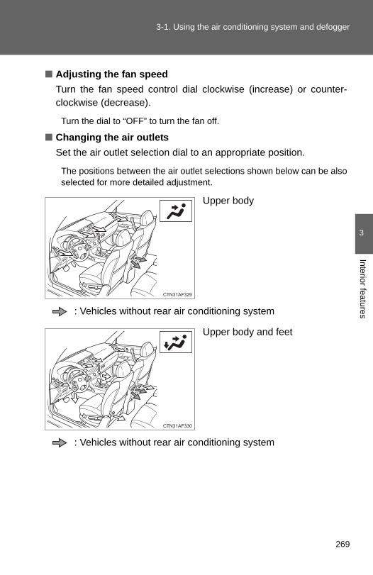
3-1. Using the air conditioning system and defogger
3
Interior features
■ Adjusting the fan speedTurn the fan speed control dial clockwise (increase) or counter-clockwise (decrease).
Turn the dial to “OFF” to turn the fan off.
■ Changing the air outletsSet the air outlet selection dial to an appropriate position.
The positions between the air outlet selections shown below can be alsoselected for more detailed adjustment.
Upper body
: Vehicles without rear air conditioning system
Upper body and feet
: Vehicles without rear air conditioning system
269

3-1. Using the air conditioning system and defogger
Feet
: Vehicles without rear air conditioning system
Without rear air conditioning system
Feet and windshield
Recirculated air mode may auto-matically switch to outside airmode.
With rear air conditioning system
Feet and windshield
Recirculated air mode may auto-matically switch to outside airmode.
270

3-1. Using the air conditioning system and defogger
3
Interior features
■ Switching between outside air and recirculated air modes
Press .
The mode switches between outside air mode (indicator off) and recircu-
lated air mode (indicator on) modes each time is pressed.
Defogging the windshield
Set the air outlet selection dial to position.
The air conditioning system oper-ates automatically.
Recirculated air mode may auto-matically switch to outside airmode.
271

3-1. Using the air conditioning system and defogger
Adjusting the position of and opening and closing the air outlets
Front center outlets
Direct air flow to the left or right,up or down.
Front side outlets
Direct air flow to the left orright, up or down.Turn the knob to open or closethe vent.
Rear center outlets (vehicles without rear air conditioning system)
Direct air flow to the left orright, up or down.Turn the knob to open or closethe vent.
272

3-1. Using the air conditioning system and defogger
3
Interior features
■Using the system in recirculated air modeThe windows will fog up more easily if the recirculated air mode is used foran extended period.
■Window defogger featureIn order to prevent the windows from fogging up, recirculated air mode mayautomatically switch to outside air mode if the ambient temperature drops.This feature can be canceled by pushing and holding the air intake modeswitch for longer than 2 seconds. The feature will be reactivated when theengine switch is turned to the “ACC” or “LOCK” position.
■When outside air temperature approaches 32°F (0°C)The air conditioning system may not operate even when is pressed.
■When the indicator light on flashes (2.7 L 4-cylinder [1AR-FE]engine only)
Press and turn off the air conditioning system before turning it ononce more. There may be a problem in the air conditioning system if the indi-cator light continues to flash. Turn the air conditioning system off and have itinspected by your Toyota dealer.
■When is selected for the air outlets usedFor your driving comfort, air flowing to the feet may be warmer than air flow-ing to the upper body depending on the position of the temperature adjust-ment dial.
■Air conditioning odors●During use, various odors from inside and outside the vehicle may enter
into and accumulate in the air conditioning system. This may then causeodor to be emitted from the vents.
●To reduce potential odors from occurring:It is recommended that the air conditioning system be set to outside airmode prior to turning the vehicle off.
273

3-1. Using the air conditioning system and defogger
CAUTION
■To prevent the windshield from fogging up
Do not set the air outlet selection dial to during cool air operation inextremely humid weather. The difference between the temperature of theoutside air and that of the windshield can cause the outer surface of thewindshield to fog up, blocking your vision.
NOTICE
■To prevent battery dischargeDo not leave the air conditioning system on longer than necessary when theengine is off.
274

3
Interior features
3-1. Using the air conditioning system and defogger
Front automatic air conditioning system∗
Airflow and outlets are automatically adjusted according to the tem-perature setting.
Control panel
Vehicles with rear air conditioning systemVehicles without rear air conditioning system
Fan speed
Individual mode
Front passenger’s sidetemperature control dial
Air conditioning on/off switch
Simultaneous mode
Rear air conditioning on/off switch
Temperature control for rear passengers
Changes the air outlets usedOff
Driver's sidetemperaturecontrol dial
Automatic mode
Windshield defogger Outside air or recirculated air mode
A
B
∗: If equipped
275
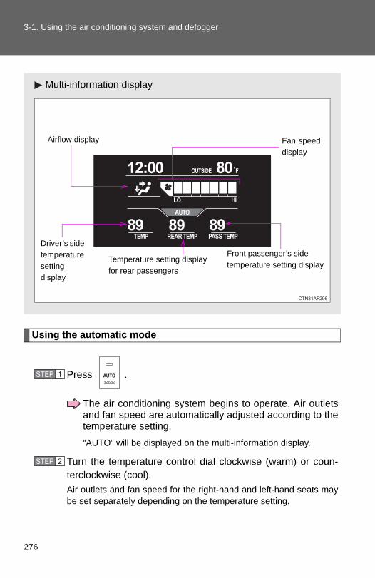
3-1. Using the air conditioning system and defogger
Using the automatic mode
Press .
The air conditioning system begins to operate. Air outletsand fan speed are automatically adjusted according to thetemperature setting.“AUTO” will be displayed on the multi-information display.
Turn the temperature control dial clockwise (warm) or coun-terclockwise (cool).Air outlets and fan speed for the right-hand and left-hand seats maybe set separately depending on the temperature setting.
Multi-information display
Front passenger’s side temperature setting display
Fan speeddisplay
Airflow display
Driver’s side temperature setting display
Temperature setting display for rear passengers
STEP 1
STEP 2
276

3-1. Using the air conditioning system and defogger
3
Interior features
Adjusting the settings
■ Adjusting the temperature settingTurn the temperature control dial clockwise (warm) or counter-clockwise (cool).
The air conditioning system switches between individual andsimultaneous modes each time (without rear air conditioningsystem) or (with rear air conditioning system) is pressed.
Simultaneous mode: Only the driver’s side temperature control dialcan be used to adjust the temperature for all seats.
The indicator status will be as follows:
Without rear air conditioning system: (off)
With rear air conditioning system: (on)
Individual mode: The temperature for the driver’s, front passen-ger’s and rear seats (→P. 286) can be adjusted separately. Operat-ing the passenger's side or rear (with rear air conditioning system)temperature control will enter individual mode.
The indicator status will be as follows:
Without rear air conditioning system: (on)
With rear air conditioning system: (off)
■ Adjusting the fan speed
Press “∧” (increase) or “∨” (decrease) on or .
The fan speed is shown on the multi-information display. (7 levels)
Press to turn the fan off.
277

3-1. Using the air conditioning system and defogger
■ Changing the air outletsPress .
The air outlets switch each time either side of is pressed. The airflow shown on the display indicates the following.
Upper body
: Vehicles without rear air conditioning system
Upper body and feet
: Vehicles without rear air conditioning system
Feet
: Vehicles without rear air conditioning system
278

3-1. Using the air conditioning system and defogger
3
Interior features
Without rear air conditioning system
Feet and windshield
Recirculated air mode may auto-matically switch to outside airmode.
With rear air conditioning system
Feet and windshield
Recirculated air mode may auto-matically switch to outside airmode.
■ Switching between outside air and recirculated air modes
Press .
The mode switches between outside air mode (indicator off) and recircu-
lated air mode (indicator on) modes each time is pressed.
279

3-1. Using the air conditioning system and defogger
Changing the rear seat settings (if equipped)
■ Adjusting the temperature settingPress “∧” on to increase the temperature and “∨” todecrease the temperature.
The air conditioning system switches between individual andsimultaneous modes each time is pressed.
Defogging the windshield
Press .
The air conditioning system oper-ates automatically.
Recirculated air mode may auto-matically switch to outside airmode.
Adjusting the position of and opening and closing the air outlets
Front center outlets
Direct air flow to the left or right,up or down.
280

3-1. Using the air conditioning system and defogger
3
Interior features
Front side outlets
Direct air flow to the left orright, up or down.Turn the knob to open or closethe vent.
Rear center outlets (vehicles without rear air conditioning system)
Direct air flow to the left orright, up or down.Turn the knob to open or closethe vent.
■Using the automatic modeFan speed is adjusted automatically in accordance with the temperature set-ting and ambient conditions. As a result, the following may occur.
● Immediately after the switch is pressed, the fan may stop for a while untilwarm or cool air is ready to flow.
●Cool air may flow to the area around the upper body when the heater ison.
■Using the system in recirculated air modeThe windows will fog up more easily if the recirculated air mode is used foran extended period.
281

3-1. Using the air conditioning system and defogger
■Switching between outside air and recirculated air modesRecirculated air mode or outside air mode may be automatically switched toin accordance with the temperature setting and the inside temperature.
■Window defogger feature
Recirculated air mode may automatically switch to (outside air) modein situations where the windows need to be defogged.
■When outside temperature approaches 32°F (0°C)The air conditioning system may not operate even when is pressed.
■Air conditioning odors●During use, various odors from inside and outside the vehicle may enter
into and accumulate in the air conditioning system. This may then causeodor to be emitted from the vents.
●To reduce potential odors from occurring:
• It is recommended that the air conditioning system be set to outside airmode prior to turning the vehicle off.
• The start timing of the blower may be delayed for a short period of timeimmediately after the air conditioning system is started in automaticmode.
CAUTION
■To prevent the windshield from fogging up
Do not use during cool air operation in extremely humid weather. The
difference between the temperature of the outside air and that of the wind-shield can cause the outer surface of the windshield to fog up, blocking yourvision.
NOTICE
■To prevent battery dischargeDo not leave the air conditioning system on longer than necessary when theengine is off.
282

3
Interior features
3-1. Using the air conditioning system and defogger
Rear manual air conditioning system∗
Airflow and outlets are automatically adjusted according to the tem-perature setting.
Temperature control dial
Changes the air outlets used
Fan speed control dial
∗: If equipped
283

3-1. Using the air conditioning system and defogger
Adjusting the settings
■ Adjusting the temperature settingTurn the temperature control dial clockwise (warm) or counter-clockwise (cool).
■ Changing the air outlets
Press the desired , or .
Air flows as shown below according to the mode selected.
Upper body
Upper body and feet
284

3-1. Using the air conditioning system and defogger
3
Interior features
Feet
■ Adjusting the fan speedTurn the fan speed control dial clockwise (increase) or counter-clockwise (decrease).
Adjusting the position of and opening and closing the roof side air outlets
Direct air flow to the left or right,up or down.
NOTICE
■To prevent battery dischargeDo not leave the air conditioning system on longer than necessary when theengine is off.
285

3-1. Using the air conditioning system and defogger
Rear automatic air conditioning system∗
Using the automatic mode
Press .
The air conditioning system will operate, and air outletsand fan speed will be set automatically.“AUTO” will be displayed on the control panel.
Turn the temperature control dial clockwise (warm) or coun-terclockwise (cool).
Airflow and outlets are automatically adjusted according to the tem-perature setting.
Airflow displayFan speed display
Temperature setting display
Fan speed control dial
OffAutomatic mode
Changes the air outlets used
Temperaturecontrol dial
STEP 1
STEP 2
∗: If equipped
286

3-1. Using the air conditioning system and defogger
3
Interior features
Adjusting the settings
■ Adjusting the temperature settingTurn the temperature control dial clockwise (warm) or counter-clockwise (cool).
■ Changing the air outlets
Press .
The air outlets change as follows each time is pressed.
Air flows as shown below according to the mode selected.
Upper body
Upper body and feet
287
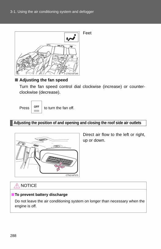
3-1. Using the air conditioning system and defogger
Feet
■ Adjusting the fan speedTurn the fan speed control dial clockwise (increase) or counter-clockwise (decrease).
Press to turn the fan off.
Adjusting the position of and opening and closing the roof side air outlets
Direct air flow to the left or right,up or down.
NOTICE
■To prevent battery dischargeDo not leave the air conditioning system on longer than necessary when theengine is off.
288

3
Interior features
3-1. Using the air conditioning system and defogger
Rear window and outside rear view mirror defoggers
Clear the rear window using the defogger.
Vehicles with manual air conditioning system
On/off
Press the button to turn on therear window defogger. Theindicator light will come on.The defoggers will automati-cally turn off after 15 to 60 min-utes. The operation timechanges according to theambient temperature and vehi-cle speed. Pressing the buttonagain also turns the defoggeroff.
Vehicles without outside rear view mirror defoggersVehicles with outside rear view mirror defoggersVehicles with automatic air conditioning system
On/off
Press the button to turn on therear window defogger. Theindicator light will come on.The defoggers will automati-cally turn off after 15 to 60 min-utes. The operation timechanges according to theambient temperature and vehi-cle speed. Pressing the buttonagain also turns the defoggeroff.
Vehicles without outside rear view mirror defoggersVehicles with outside rear view mirror defoggers
A
B
A
B
289

3-1. Using the air conditioning system and defogger
■The defogger can be operated whenVehicles without smart key system
The engine switch is in the “ON” position.
Vehicles with smart key system
The “ENGINE START STOP” switch is in IGNITION ON mode.
■Outside rear view mirror defoggers (vehicles with outside rear viewmirror defoggers)Turning the rear window defogger on will turn the outside rear view mirrordefoggers on.
CAUTION
■Outside rear view mirror defoggers (vehicles with outside rear viewmirror defoggers)Do not touch the outside surface of the rear view mirrors, as they canbecome very hot and cause burns.
290
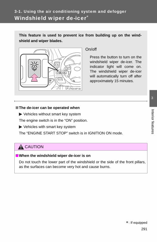
3
Interior features
3-1. Using the air conditioning system and defogger
Windshield wiper de-icer∗
■The de-icer can be operated whenVehicles without smart key system
The engine switch is in the “ON” position.
Vehicles with smart key system
The “ENGINE START STOP” switch is in IGNITION ON mode.
CAUTION
■When the windshield wiper de-icer is onDo not touch the lower part of the windshield or the side of the front pillars,as the surfaces can become very hot and cause burns.
This feature is used to prevent ice from building up on the wind-shield and wiper blades.
On/off
Press the button to turn on thewindshield wiper de-icer. Theindicator light will come on.The windshield wiper de-icerwill automatically turn off afterapproximately 15 minutes.
∗: If equipped
291

3-1. Using the air conditioning system and defogger
Using the steering wheel climate remote control switches∗
Using the automatic mode
Press .
The air conditioning system will operate, and air outletsand fan speed will be set automatically.“AUTO” will be displayed on the multi-information display.
Press “∧” on to increase the temperature and “∨” todecrease the temperature.
Adjusting the temperature setting
Press “∧” on to increase the temperature and “∨” to decreasethe temperature.
Turning off the fan
Press .
Some air conditioning features can be controlled using the switcheson the steering wheel.
Temperature controlOffAutomatic mode
STEP 1
STEP 2
∗: If equipped
292

3-2. Using the audio system
3
Interior features
Audio system
With navigation systemOwners of models equipped with a navigation system should referto the “Navigation System Owner's Manual”.
Without navigation systemType A: CD player and AM/FM radio
Type B: CD player and AM/FM radio (with CD changer controller)
293

3-2. Using the audio system
Type C: CD player with changer and AM/FM radio
Title Page
Using the radio P. 297
Using the CD player P. 304
Playing back MP3 and WMA discs P. 312
Operating an iPod P. 320
Operating a USB memory P. 327
Optimal use of the audio system P. 335
Using the AUX port P. 339
Using the steering wheel audio switches P. 341
294

3-2. Using the audio system
3
Interior features
Language settings (type B and C)
The language used for all voice guidance, voice recognition and mes-sages may be changed.
Press .
Press (MORE).
Press (LANG).
Press the that corresponds to the desired language.
For vehicles sold in the U.S.A.
“ENG” (English) or “ESP” (Spanish)
For vehicles sold in Canada“ENG” (English) or “FRAN” (French)
■Using cellular phonesInterference may be heard through the audio system's speakers if a cellularphone is being used inside or close to the vehicle while the audio system isoperating.
STEP 1
STEP 2
STEP 3
STEP 4
295

3-2. Using the audio system
CAUTION
■For vehicles sold in U.S.A. and Canada●Part 15 of the FCC Rules
FCC Warning:Any unauthorized changes or modifications to this equipment will void theuser’s authority to operate this device.
●Laser products
• Do not take this unit apart or attempt to make any changes yourself. This is an intricate unit that uses a laser pickup to retrieve informationfrom the surface of compact discs. The laser is carefully shielded sothat its rays remain inside the cabinet. Therefore, never try to disas-semble the player or alter any of its parts since you may be exposed tolaser rays and dangerous voltages.
• This product utilizes a laser.Use of controls or adjustments or performance of procedures otherthan those specified herein may result in hazardous radiation expo-sure.
NOTICE
■To prevent battery dischargeDo not leave the audio system on longer than necessary when the engine isoff.
■To avoid damaging the audio systemTake care not to spill drinks or other fluids over the audio system.
296
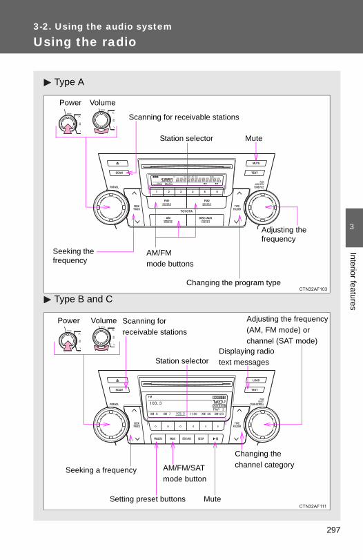
3
Interior features
3-2. Using the audio system
Using the radio
Type A
Type B and C
Volume
Seeking the frequency
Station selector
AM/FM mode buttons
Adjusting the frequency
Power
Scanning for receivable stations
Changing the program type
Mute
Power Volume Adjusting the frequency(AM, FM mode) or channel (SAT mode)
Seeking a frequency
Displaying radio text messages
AM/FM/SAT mode button
Scanning for receivable stations
Station selector
Setting preset buttons
Changing the channel category
Mute
297

3-2. Using the audio system
Setting station presets (excluding XM® Satellite Radio)
Search for desired stations by turning or , or
pressing “∧” or “∨” on .
Press and hold the button (from to ) the stationis to be set to until you hear a beep.
Type B and C: Each time is pressed, station pages arechanged. There are a total of 6 pages.
Scanning radio stations (excluding XM® Satellite Radio)
■ Scanning the preset radio stationsPress and hold until you hear a beep.Preset stations will be played for 5 seconds each.
When the desired station is reached, press once again.
■ Scanning all radio stations within rangePress .All stations with reception will be played for 5 seconds each.
When the desired station is reached, press once again.
■ Displaying radio text messages (for type B and C, FM modeonly)When a new radio text message is received, “MSG” is shown onthe display. To display the message, press .
If the text continues past the end of the display, “ ” is displayed. Press
and hold until you hear a beep.
Text messages are not displayed while driving.
STEP 1
STEP 2
STEP 1
STEP 2
STEP 1
STEP 2
298

3-2. Using the audio system
3
Interior features
XM® Satellite Radio (type B and C)
■ Receiving XM® Satellite RadioPress .The display changes as follows each time is pressed.AM → FM → XM
Turn to select the desired channel in all the categories,
or press “∧” or “∨” on to select the desired channel in
the current category.
■ Setting XM® Satellite Radio channel presetsSelect the desired channel. Press and hold a button(from to ) until you hear a beep.
■ Changing the channel category
Press “∧” or “∨” on the .
■ Scanning XM® Satellite Radio channels● Scanning channels in the current category
Press .When the desired channel is reached, press again.
● Scanning preset channels
Press and hold until you hear a beep.When the desired channel is reached, press again.
STEP 1
STEP 2
STEP 1
STEP 2
STEP 1
STEP 2
299

3-2. Using the audio system
■ Displaying text informationPress .
Each time is pressed, the display changes in the following order: Title (song/program title) → Name (artist name/feature)/Title (song/pro-gram title).
Silencing the sound
Type A
Press .
Type B and C
Press .
300

3-2. Using the audio system
3
Interior features
■When the battery is disconnectedAll preset stations are erased. (type A only)
■Reception sensitivity●Type B and C ⎯ Cargo loaded on the roof luggage carrier, especially
metal objects, may adversely affect the reception of XM® Satellite Radio.
●Maintaining perfect radio reception at all times is difficult due to the con-tinually changing position of the antenna, differences in signal strengthand surrounding objects, such as trains and transmitters.
●Pole type antenna ⎯ The radio antenna is mounted on the right-sidefront fender. The antenna can be removed from the base by turning it.
●Print type antenna ⎯ The radio antenna is mounted inside the left-siderear quarter window. To maintain clear radio reception, do not attachmetallic window tinting or other metallic objects to the antenna wiremounted inside the left-side rear quarter window.
■XM® Satellite Radio (type B and C)An XM® Satellite Radio is a tuner designed exclusively to receive broadcastsprovided under a separate subscription. Availability is limited to the 48 con-tiguous states and 10 Canadian provinces.
●XM® subscriptionsFor detailed information about XM® Satellite Radio or to subscribe:U.S.A. ⎯Visit on the web at www.xmradio.com or call 1-800-967-2346.Canada ⎯Visit on the web at www.xmradio.ca or call 1-877-438-9677.
●Radio IDYou will need the radio ID when activating XM® service or reporting a
problem. Select “CH000” using , and the receiver's 8-character ID
number will appear.
●Satellite tunerThe tuner supports only Audio Services (Music and Talk) and the accom-panying Text Information of XM® Satellite Radio.
301
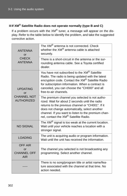
3-2. Using the audio system
■ If XM® Satellite Radio does not operate normally (type B and C)If a problem occurs with the XM® tuner, a message will appear on the dis-play. Refer to the table below to identify the problem, and take the suggestedcorrective action.
ANTENNA or
CHECK ANTENNA
The XM® antenna is not connected. Check whether the XM® antenna cable is attached securely.
There is a short-circuit in the antenna or the sur-rounding antenna cable. See a Toyota certified dealer.
UPDATINGor
CHANNEL NOT AUTHORIZED
You have not subscribed to the XM® Satellite Radio. The radio is being updated with the latest encryption code. Contact the XM® Satellite Radio for subscription information. When a contract is canceled, you can choose the “CH000” and all free-to-air channels.
The premium channel you selected is not autho-rized. Wait for about 2 seconds until the radio returns to the previous channel or “CH001”. If it does not change automatically, select another channel. If you want to listen to the premium chan-nel, contact the XM® Satellite Radio.
NO SIGNALThe XM® signal is too weak at the current location. Wait until your vehicle reaches a location with a stronger signal.
LOADING The unit is acquiring audio or program information. Wait until the unit has received the information.
OFF AIR or
CHANNEL OFF AIR
The channel you selected is not broadcasting any programming. Select another channel.
-----There is no song/program title or artist name/fea-ture associated with the channel at that time. No action needed.
302

3-2. Using the audio system
3
Interior features
Contact the XM® Listener Care Center at 1-800-967-2346 (U.S.A.) or 1-877-438-9677 (Canada).
■Certifications for the radio tunerThis equipment has been tested and found to comply with the limits for aclass B digital device, pursuant to Part 15 of the FCC Rules. These limits aredesigned to provide reasonable protection against harmful interference in aresidential installation. This equipment generates, uses and can radiateradio frequency energy and, if not installed and used in accordance with theinstructions, may cause harmful interference to radio communications. How-ever, there is no guarantee that interference will not occur in a particularinstallation.
If this equipment does cause harmful interference to radio or televisionreception, which can be determined by turning the equipment off and on, theuser is encouraged to try to correct the interference by trying one or more ofthe following:
●Reorienting or relocating the receiving antenna.
● Increasing the separation between the equipment and receiver.
●Connecting the equipment into an outlet on a circuit different from that towhich the receiver is connected.
●Consulting the dealer or an experienced radio/TV technician for help.
NOTICE
■To prevent damage, remove the antenna in the following cases. (mast type antenna)●The antenna will touch the ceiling of a garage.
●A cover will be put on the vehicle.
---or
CHANNEL NOT AVAILABLE
The channel you selected is no longer available. Wait for about 2 seconds until the radio returns to the previous channel or “CH001”. If it does not change automatically, select another channel.
303

3-2. Using the audio system
Using the CD player
Type A
Type B and C
Volume
Random playback
Track selection
Repeat play
Playback
Power CD eject Displaying text messageSearch playback
CD slot
ReverseFast-forward
Mute
Power Volume
CD load (type C only)
Searchingplayback
CD eject
Selecting a track/fast-forwardingand rewinding
Displaying text messages
Selector buttons
Playback Playback/pause
Selecting a track
304

3-2. Using the audio system
3
Interior features
Loading CDs
■ Loading a CDType A and BInsert a CD.
Type CPress .When the indicator on the slot turns from amber to green,insert a CD.
■ Loading multiple CDs (type C only)Press and hold until you hear a beep.When the indicator on the slot turns from amber to green,insert a CD.The indicator on the slot turns to amber when the CD is inserted.
When the indicator on the slot turns from amber to greenagain, insert the next CD.Repeat the procedure for the remaining CDs.
To cancel, press . If you do not insert a disc within 15 sec-onds, loading will be canceled automatically.
STEP 1
STEP 2
STEP 1
STEP 2
STEP 3
305

3-2. Using the audio system
Ejecting CDs
■ Ejecting a CDType A and BPress and remove the CD.
Type C
To select the CD to be ejected, press ( ) or
( ).
The selected CD number is shown on the display.
Press and remove the CD.
■ Ejecting all the CDs (type C only)Press and hold until you hear a beep, and then remove theCDs.
Selecting a track
Press “∧” to move up or “∨” to move down using until the
desired track number is displayed.
Fast-forwarding and reversing tracks
To fast-forward or reverse, press and hold “∧” or “∨” on .
Scanning tracks
Press .The first ten seconds of each track will be played.
To cancel, press again.
Press again when the desired track is reached.
STEP 1
STEP 2
STEP 1
STEP 2
306

3-2. Using the audio system
3
Interior features
Selecting a CD (type B with a CD changer and type C)
■ Selecting a CD to playPress ( ) or ( ).
■ Scanning loaded CDsPress and hold until you hear a beep.The first ten seconds of the first track on each CD will be played.
To cancel, press again.
Press again when the desired CD is reached.
Playing and pausing tracks (type B and C)
Press .
Random playback
■ Current CDPress (RAND) or (RDM).
Songs are played in random order.
To cancel, press the button once more (type A and type B without a CDchanger), or twice more (type B with a CD changer and type C).
■ All CDs (type B with a CD changer and type C)
Press (RDM) twice.
Tracks on all loaded CDs are played in random order.
To cancel, press the button again.
STEP 1
STEP 2
307
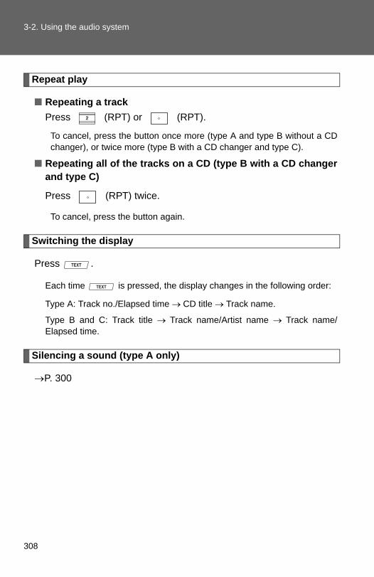
3-2. Using the audio system
Repeat play
■ Repeating a trackPress (RPT) or (RPT).
To cancel, press the button once more (type A and type B without a CDchanger), or twice more (type B with a CD changer and type C).
■ Repeating all of the tracks on a CD (type B with a CD changerand type C)
Press (RPT) twice.
To cancel, press the button again.
Switching the display
Press .
Each time is pressed, the display changes in the following order:
Type A: Track no./Elapsed time → CD title → Track name.
Type B and C: Track title → Track name/Artist name → Track name/Elapsed time.
Silencing a sound (type A only)
→P. 300
308

3-2. Using the audio system
3
Interior features
■DisplayUp to 12 characters can be displayed at a time.If there are 13 characters or more, pressing and holding for 1 secondor more will display the remaining characters.A maximum of 24 characters can be displayed.
If is pressed for 1 second or more again or has not been pressed for6 seconds or more, the display will return to the first 12 characters.
Depending on the contents recorded, the characters may not be displayedproperly or may not be displayed at all.
■Error messages“CD CHECK”: This indicates a problem either in the CD or inside the player.
The CD may be dirty, damaged or inserted up-side down.
“WAIT” or “PLEASE WAIT”: Operation has stopped due to a high tempera-ture inside the player. Wait for a while and then
press or . Contact yourToyota dealer if the CD still cannot be playedback.
■Discs that can be usedDiscs with the marks shown below can be used.Playback may not be possible depending on recording format or disc fea-tures, or due to scratches, dirt or deterioration.
CDs with copy-protect features may not be used.
■CD player protection featureTo protect the internal components, playback is automatically stopped whena problem is detected while the CD player is being used.
■ If CDs are left inside the CD player or in the ejected position forextended periodsCDs may be damaged and may not play properly.
309
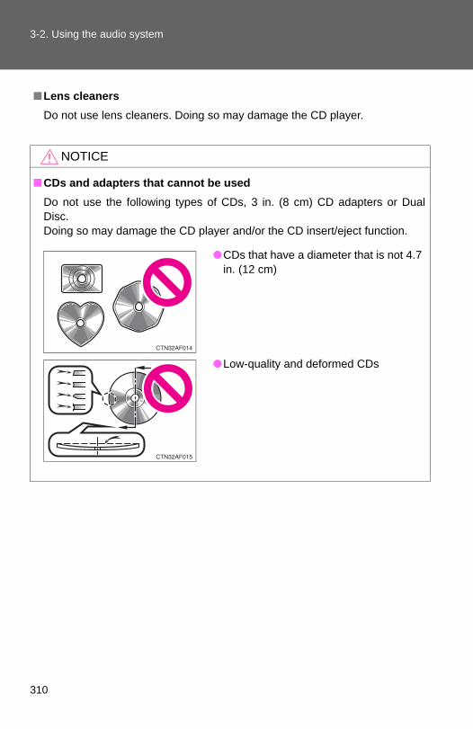
3-2. Using the audio system
■Lens cleanersDo not use lens cleaners. Doing so may damage the CD player.
NOTICE
■CDs and adapters that cannot be usedDo not use the following types of CDs, 3 in. (8 cm) CD adapters or DualDisc.Doing so may damage the CD player and/or the CD insert/eject function.
●CDs that have a diameter that is not 4.7in. (12 cm)
●Low-quality and deformed CDs
310

3-2. Using the audio system
3
Interior features
NOTICE
■CD player precautionsFailure to follow the precautions below may result in serious damage to theCDs or the player itself.
●Do not insert anything other than CDs into the CD slot.
●Do not apply oil to the CD player.
●Store CDs away from direct sunlight.
●Never try to disassemble any part of the CD player.
●CDs with a transparent or translucentrecording area
●CDs that have had tape, stickers or CD-R labels attached to them, or that havehad the label peeled off
●Do not insert more than one CD at atime.
311

3-2. Using the audio system
Playing back MP3 and WMA discs
Type A
Type B and C
Volume
Random playbackFile selectionRepeat play
Playback
Power CD ejectDisplaying text messageSearch playback
CD slot
Folder selection
File selection
Reverse Fast-forward
Mute
Power VolumeDisplaying text messages
CD eject
Playback
Playback/pause
Selecting a file
CD load(type C only)Selector buttons
Selecting a folder and file
Searching playback
Selecting a file/fast-forwardingand rewinding
312

3-2. Using the audio system
3
Interior features
Loading and ejecting MP3 and WMA discs
→P. 304
Selecting MP3 and WMA discs (type B with a CD changer and type C)
→P. 307
Selecting and scanning a folder
■ Selecting folders one at a time
Press “∧” or “∨” on to select the desired folder.
■ Scanning the first file of all the folders
Press and hold until you hear a beep.The first ten seconds of the first file in each folder will be played.
When the desired folder is reached, press again.
■ Returning to the first folder
Press and hold “∨” on until you hear a beep.
Selecting and scanning files
■ Selecting one file at a time
Turn or , or press “∧” or “∨” on to select the
desired file.
■ Selecting the desired file by cueing the files in the folderPress .
When the desired file is reached, press once again.
STEP 1
STEP 2
313

3-2. Using the audio system
Fast-forwarding and reversing files
To fast-forward or reverse, press and hold “∧” or “∨” on .
Playing and pausing files (type B and C)
Press .
Random playback
■ Playing files from a particular folder in random orderPress (RAND) or (RDM).
To cancel, press the button once more (type A and type B without a CDchanger), or twice more (type B with a CD changer and type C).
■ Playing all of the files on a disc in random orderType APress and hold (RAND) until you hear a beep.
To cancel, press the button again.
Type B and C
Press (RDM) twice.
To cancel, press the button again.
314

3-2. Using the audio system
3
Interior features
Repeat play
■ Repeating a filePress (RPT) or (RPT).
To cancel, press the button once more (type A and type B without a CDchanger), or twice more (type B with a CD changer and type C).
■ Repeating all of the files on a folderType APress and hold (RPT) until you hear a beep.
To cancel, press the button again.
Type B and C
Press (RPT) twice.
To cancel, press the button once more (type A and type B without a CDchanger), or twice more (type B with a CD changer and type C).
■ Repeating all of the files in a disc (type B with a CD changerand type C)
Press (RPT) three times.
To cancel, press the same button again.
Switching the display
Press .
Each time is pressed, the display changes in the following order:
Type A: Folder no./File no./Elapsed time → Folder name → File name →Album title (MP3 only) → Track title → Artist name.
Type B and C: Track title → Track title/Artist name → Track title/Albumname (MP3 only) → Track title/Elapsed time.
Silencing a sound (type A only)
→P. 300
315

3-2. Using the audio system
■Display (type A only)→P. 309
■Error messages“CD CHECK”:This indicates a problem either in the CD or inside the player.
The CD may be dirty, damaged or inserted up-side down.
“NO MUSIC”: This indicates that MP3/WMA files are not included in the CD.
“WAIT” or “PLEASE WAIT”: Operation has stopped due to a high tempera-ture inside the player. Wait for a while and then
press or . Contact yourToyota dealer if the CD still cannot be played.
■Discs that can be used→P. 309
■CD player protection feature→P. 309
■ If CDs are left inside the CD player or in the ejected position forextended periods→P. 309
■Lens cleaners→P. 310
316

3-2. Using the audio system
3
Interior features
■MP3 and WMA filesMP3 (MPEG Audio LAYER3) is a standard audio compression format.
Files can be compressed to approximately 1/10 of their original size by usingMP3 compression.
WMA (Windows Media Audio) is a Microsoft audio compression format.
This format compresses audio data to a size smaller than that of the MP3format.
There is a limit to the MP3 and WMA file standards that can be used and tothe media/formats on which the files are recorded.
●MP3 file compatibility
• Compatible standardsMP3 (MPEG1 LAYER3, MPEG2 LSF LAYER3)
• Compatible sampling frequenciesMPEG1 LAYER3: 32, 44.1, 48 (kHz)MPEG2 LSF LAYER3: 16, 22.05, 24 (kHz)
• Compatible bit rates (compatible with VBR)MPEG1 LAYER3: 64, 80, 96, 112, 128, 160, 192, 224, 256, 320 (kbps)MPEG2 LSF LAYER3: 64, 80, 96, 112, 128, 144, 160 (kbps)
• Compatible channel modes: stereo, joint stereo, dual channel andmonaural
●WMA file compatibility
• Compatible standardsWMA Ver. 7, 8, 9
• Compatible sampling frequencies32, 44.1, 48 (kHz)
• Compatible bit rates (only compatible with 2-channel playback)Ver. 7, 8: CBR 48, 64, 80, 96, 128, 160, 192 (kbps)Ver. 9: CBR 48, 64, 80, 96, 128, 160, 192, 256, 320 (kbps)
●Compatible media
Media that can be used for MP3 and WMA playback are CD-Rs and CD-RWs.
Playback in some instances may not be possible, depending on the statusof the CD-R or CD-RW. Playback may not be possible or the audio mayjump if the disc is scratched or marked with fingerprints.
317

3-2. Using the audio system
●Compatible disc formats
The following disc formats can be used.
• Disc formats: CD-ROM Mode 1 and Mode 2CD-ROM XA Mode 2, Form 1 and Form 2
• File formats: ISO9660 Level 1, Level 2, (Romeo, Joliet)MP3 and WMA files written in any format other than those listed abovemay not play correctly, and their file names and folder names may notbe displayed correctly.
Items related to standards and limitations are as follows.
• Maximum directory hierarchy: 8 levels• Maximum length of folder names/file names: 32 characters• Maximum number of folders: 192 (including the root)• Maximum number of files per disc: 255
●File names
The only files that can be recognized as MP3/WMA and played are thosewith the extension .mp3 or .wma.
●Multi-sessions
As the audio system is compatible with multi-sessions, it is possible to playdiscs that contain MP3 and WMA files. However, only the first session canbe played.
● ID3 and WMA tags
ID3 tags can be added to MP3 files, making it possible to record the tracktitle, artist name, etc.
The system is compatible with ID3 Ver. 1.0, 1.1, and Ver. 2.2, 2.3 ID3 tags.(The number of characters is based on ID3 Ver. 1.0 and 1.1.)
WMA tags can be added to WMA files, making it possible to record thetrack title and artist name in the same way as with ID3 tags.
●MP3 and WMA playback
When a disc containing MP3 or WMA files is inserted, all files on the discare first checked. Once the file check is finished, the first MP3 or WMA fileis played. To make the file check finish more quickly, we recommend youdo not write in any files other than MP3 or WMA files or create any unnec-essary folders.
If the discs contain a mixture of music data and MP3 or WMA format data,only music data can be played.
318

3-2. Using the audio system
3
Interior features
●Extensions
If the file extensions .mp3 and .wma are used for files other than MP3 andWMA files, they will be mistakenly recognized and played as MP3 andWMA files. This may result in large amounts of interference and damageto the speakers.
●Playback
• To play MP3 file with steady sound quality, we recommend a fixed bitrate of at least 128 kbps and a sampling frequency of 44.1 kHz.
• CD-R or CD-RW playback may not be possible in some instances,depending on the characteristics of the disc.
• There is a wide variety of freeware and other encoding software forMP3 and WMA files on the market, and depending on the status of theencoding and the file format, poor sound quality or noise at the start ofplayback may result. In some cases, playback may not be possible atall.
• When files other than MP3 or WMA files are recorded on a disc, it maytake more time to recognize the disc and in some cases, playback maynot be possible at all.
• Microsoft, Windows, and Windows Media are the registered trade-marks of Microsoft Corporation in the U.S. and other countries.
NOTICE
■CDs and adapters that cannot be used→P. 310
■CD player precautions→P. 311
319

3-2. Using the audio system
Operating an iPod∗
∗: If equipped
Connecting an iPod enables you to enjoy music from the vehiclespeakers.
■ Connecting an iPod
Open the cover and connect an iPod using an iPod cable.Turn on the power of the iPod if it is not turned on.
STEP 1
Vehicles without seat heater
Vehicles with seat heater
320

3-2. Using the audio system
3
Interior features
Press .
■ Control panel
STEP 2
Power Volume Selector knob
Displaying text messages
Selector buttons
Playback
Playback/pauseSelecting a track/fast-forwardingand rewinding
321

3-2. Using the audio system
Selecting a play mode
Press (BROWSE) to select iPod menu mode.
Press that corresponds to the desired play mode.
Pressing (MORE) to change to the second selection list.
■ Play mode list
Depending on the model, the name of your iPod may be displayed atthe top of the list.
Play mode First selection
Second selection
Third selection
Fourth selection
PLIST Playlist select
Songs select - -
ARTIST Artist select Albums select
Songs select -
ALBUM Albums select
Songs select - -
GENRE Genre select Artists select Albums select
Songs select
SONGS Songs select - - -
PODCST Albums select
Songs select - -
COMPSR Composers select
Albums select
Songs select -
BOOK Songs select - - -
STEP 1
STEP 2
322

3-2. Using the audio system
3
Interior features
■ Selecting a list
Turn to display the first selection list.
Press to select the desired item.
Repeat the same procedure to select the desired song name.
To return to the previous selection list, press ( ).
Selecting songs from a song list
Press (LIST).
The current playlist is displayed.
Turn to select the desired song.
Pressing returns the screen from list display to the previous
screen.
STEP 1
STEP 2
STEP 3
STEP 1
STEP 2
323

3-2. Using the audio system
Selecting songs
Turn or press “∧” or “∨” on to select the desired song.
Playing and pausing songs
Press .
Fast-forwarding and rewinding songs
Press and hold “∧” or “∨” on .
Shuffle playback
■ Playing songs from one playlist or album in random orderPress (RDM).
To cancel, press the button twice.
■ Playing songs from all the playlists or albums in random orderPress (RDM) twice.
To cancel, press the button again.
Repeat play
Press (RPT).
To cancel, press the button again.
Even when the repeat play option has not been selected, playback willautomatically continue from the first song in the current play list once thelast song has ended.
324

3-2. Using the audio system
3
Interior features
Switching the display
Press .
Each time is pressed, the display changes in the following order: Track title → Track title/Artist name → Track title/Album name → Tracktitle/Elapsed time
■About iPod●Apple is not responsible for the operation of this device or its compliance
with safety and regulatory standards.
● iPod is a trademark of Apple Inc., registered in the U.S. and other coun-tries.
■ iPod functions●When an iPod is connected and the audio source is changed to iPod
mode, the iPod will resume play from the same point in which it was lastused.
●Depending on the iPod that is connected to the system, certain functionsmay not be available. Disconnecting the device and reconnecting it onceagain may resolve some malfunctions.
■ iPod problemsTo resolve most problems encountered when using your iPod, disconnectyour iPod from the vehicle iPod connection and reset it. For instructions on how to reset your iPod, refer to your iPod Owner's Man-ual.
■Error messages“iPod ERROR”: This indicates a problem in the iPod, inside the
USB box or the connection between them.
“NO SONGS”: This indicates that there is no music data in theiPod.
“UPDATE YOUR iPod”: This indicates that the version of the iPod is notcompatible.
325

3-2. Using the audio system
■Compatible models
Depending on differences between models or software version etc., somemodels listed above might be incompatible with this system. iPod 4th generation and earlier models are not compatible with this system. iPhone, iPod mini, iPod shuffle and iPod photo are not compatible with thissystem.
Items related to standards and limitations are as follows:
●Maximum number of lists in a device: 9999
●Maximum number of songs in a device: 65025
●Maximum number of songs per list: 65025
CAUTION
■Caution while drivingDo not connect the iPod or operate the controls.
NOTICE
■To prevent damage to iPod●Do not leave the iPod in the vehicle. The temperature inside may become
high, resulting in damage to the player.
●Do not push down on or apply unnecessary pressure to the iPod while it isconnected as this may damage the iPod or its terminal.
●Do not insert foreign objects into the port as this may damage the iPod orits terminal.
Model Generation Software version
iPod 5th generation Ver. 1.2.0 or higher
iPod nano 1st generation Ver. 1.3.0 or higher
2nd generation Ver. 1.1.2 or higher
3rd generation Ver. 1.0.0 or higher
iPod touch 1st generation Ver. 1.1.0 or higher
iPod classic 1st generation Ver. 1.0.0 or higher
326

3
Interior features
3-2. Using the audio system
Operating a USB memory∗
Connecting a USB memory enables you to enjoy music from thevehicle speakers.
■ Connecting a USB memoryOpen the cover and connect a USB memory.Turn on the power of the USB memory if it is not turned on.
STEP 1
Vehicles without seat heater
Vehicles with seat heater
∗: If equipped
327

3-2. Using the audio system
Press .
■ Control panel
STEP 2
Power Volume Selector knob
Displaying text messages
Playback
Playback/pause
Searchingplayback
Selector buttons
Selecting a folder and fileSelecting a track/
fast-forwardingand rewinding
328
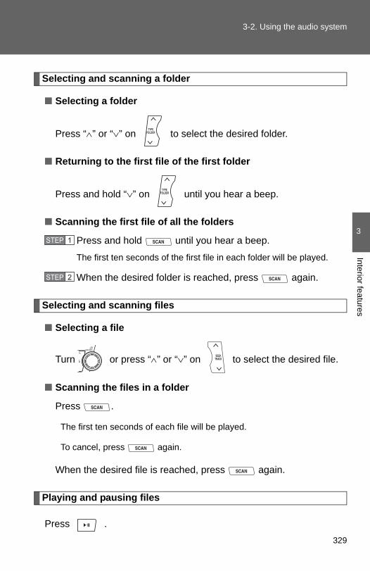
3-2. Using the audio system
3
Interior features
Selecting and scanning a folder
■ Selecting a folder
Press “∧” or “∨” on to select the desired folder.
■ Returning to the first file of the first folder
Press and hold “∨” on until you hear a beep.
■ Scanning the first file of all the folders
Press and hold until you hear a beep.
The first ten seconds of the first file in each folder will be played.
When the desired folder is reached, press again.
Selecting and scanning files
■ Selecting a file
Turn or press “∧” or “∨” on to select the desired file.
■ Scanning the files in a folder
Press .
The first ten seconds of each file will be played.
To cancel, press again.
When the desired file is reached, press again.
Playing and pausing files
Press .
STEP 1
STEP 2
329

3-2. Using the audio system
Fast-forwarding and rewinding files
Press and hold “∧” or “∨” on .
Random playback
■ Playing files from a folder in random order
Press (RDM).
To cancel, press the button twice.
■ Playing all the files from a USB memory in random orderPress (RDM) twice.
To cancel, press the button again.
Repeat play
■ Repeating a file
Press (RPT).
To cancel, press the button twice.
■ Repeating all the files in a folder
Press (RPT) twice.
To cancel, press the button again.
Switching the display
Press .
Each time is pressed, the display changes in the following order: Track title → Track title/Artist name → Track title/Album name → Tracktitle/Elapsed time
330

3-2. Using the audio system
3
Interior features
■USB memory functionsDepending on the USB memory that is connected to the system, certainfunctions may not be available. Disconnecting the device and reconnecting itonce again may resolve some malfunctions.
■Error messages“USB ERROR”: This indicates a problem either in the USB memory or
inside the USB box or connection between them.
“NO SUPPORT”: This indicates that no MP3/WMA files are included in theUSB memory.
■USB memory●Compatible device
USB memory that can be used for MP3 and WMA playback.
Depending on the type of USB device, playback may not be possible.
●Compatible device formats
The following device formats can be used:
• USB communication formats: USB2.0 FS (12 mbps)• File formats: FAT16/32 (Windows)• Correspondence class: Mass storage class
MP3 and WMA files written in any format other than those listed abovemay not play correctly, and their file names and folder names may notbe displayed correctly.
Items related to standards and limitations are as follows:
• Maximum directory hierarchy: 8 levels• Maximum number of folder in device: 999 (including the root)• Maximum number of files in device: 65025• Maximum number of files per folder: 255
331

3-2. Using the audio system
●MP3 and WMA files
MP3 (MPEG Audio LAYER 3) is a standard audio compression format.
Files can be compressed to approximately 1/10 of their original size usingMP3 compression.
WMA (Windows Media Audio) is a Microsoft audio compression format.
This format compresses audio data to a size smaller than that of the MP3format.
There is a limit to the MP3 and WMA file standards that can be used and tothe media/formats on which the files are recorded.
●MP3 file compatibility
• Compatible standardsMP3 (MPEG1 AUDIO LAYERII, III, MPEG2 AUDIO LAYERII, III,MPEG2.5)
• Compatible sampling frequenciesMPEG1 AUDIO LAYERII, III: 32, 44.1, 48 (kHz)MPEG2 AUDIO LAYERII, III: 16, 22.05, 24 (kHz)MPEG2.5: 8, 11.025, 12 (kHz)
• Compatible bit rates (compatible with VBR)MPEG1 AUDIO LAYERII, III: 32-320 (kbps)MPEG2 AUDIO LAYERII, III: 32-160 (kbps)MPEG2.5: 32-160 (kbps)
• Compatible channel modes: stereo, joint stereo, dual channel andmonaural
●WMA file compatibility
• Compatible standardsWMA Ver. 9
• Compatible sampling frequenciesHIGH PROFILE 32, 44.1, 48 (kHz)
• Compatible bit ratesHIGH PROFILE 32-320 (kbps, VBR)
●File names
The only files that can be recognized as MP3/WMA and played are thosewith the extension .mp3 or .wma.
332

3-2. Using the audio system
3
Interior features
● ID3 and WMA tags
ID3 tags can be added to MP3 files, making it possible to record the tracktitle, artist name, etc.
The system is compatible with ID3 Ver. 1.0, 1.1, and Ver. 2.2, 2.3, 2.4 ID3tags. (The number of characters is based on ID3 Ver. 1.0 and 1.1.)
WMA tags can be added to WMA files, making it possible to record thetrack title and artist name in the same way as with ID3 tags.
●MP3 and WMA playback
When a device containing MP3 or WMA files is plugged in, all files in theUSB memory device are first checked. Once the file check is finished, thefirst MP3 or WMA file is played. To make the file check finish more quickly,we recommend you do not write in any files other than MP3 or WMA filesor create any unnecessary folders.
●Extensions
If the file extensions .mp3 and .wma are used for files other than MP3 andWMA files, they will be mistakenly recognized and played as MP3 andWMA files. This may result in large amounts of interference and damageto the speakers.
●Playback
• To play MP3 files with steady sound quality, we recommend a fixed bitrate of at least 128 kbps and a sampling frequency of 44.1 kHz.
• There is a wide variety of freeware and other encoding software forMP3 and WMA files on the market, and depending on the status of theencoding and the file format, poor sound quality or noise at the start ofplayback may result. In some cases, playback may not be possible atall.
• Microsoft, Windows, and Windows Media are the registered trade-marks of Microsoft Corporation in the U.S.A. and other countries.
CAUTION
■Caution while drivingDo not use a USB memory, or connect a USB memory.
333

3-2. Using the audio system
NOTICE
■To prevent damage to a USB memory●Do not leave a USB memory in the vehicle. The temperature inside may
become high, resulting in damage to the player.
●Do not push down on or apply unnecessary pressure to the USB memorywhile it is connected as this may damage the USB memory or its terminal.
●Do not insert foreign objects into the port as this may damage the USBmemory or its terminal.
334

3
Interior features
3-2. Using the audio system
Optimal use of the audio system
Type A
Type B and C
Adjusting the sound quality and ASL
Adjusting the sound quality and ASLSelector buttons
Menu button
335
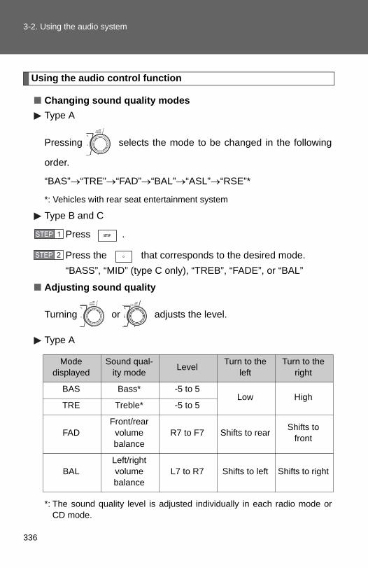
3-2. Using the audio system
Using the audio control function
■ Changing sound quality modesType A
Pressing selects the mode to be changed in the following
order.
“BAS”→“TRE”→“FAD”→“BAL”→“ASL”→“RSE”*
*: Vehicles with rear seat entertainment system
Type B and C
Press .
Press the that corresponds to the desired mode.“BASS”, “MID” (type C only), “TREB”, “FADE”, or “BAL”
■ Adjusting sound quality
Turning or adjusts the level.
Type A
*: The sound quality level is adjusted individually in each radio mode orCD mode.
STEP 1
STEP 2
Mode displayed
Sound qual-ity mode Level Turn to the
leftTurn to the
right
BAS Bass* -5 to 5Low High
TRE Treble* -5 to 5
FADFront/rear
volume balance
R7 to F7 Shifts to rear Shifts to front
BALLeft/right volume balance
L7 to R7 Shifts to left Shifts to right
336

3-2. Using the audio system
3
Interior features
Type B and C
*: The sound quality level is adjusted individually in each audiomode.
■ Adjusting the Automatic Sound Levelizer (ASL)Type A
When “ASL” is selected, turning to the right changes the
amount of “ASL” in the order of “LOW”, “MID” and “HIGH”.
Turning to the left turns “ASL” off.
ASL automatically adjusts the volume and tone quality according to vehi-cle speed.
Mode displayed
Sound qual-ity mode Level Turn to the
leftTurn to the
right
BASS Bass* -5 to 5
Low HighMID Mid-range*(type C only) -5 to 5
TREB Treble* -5 to 5
FADEFront/rear
volume balance
F7 to R7 Shifts to rear Shifts to front
BALLeft/right volume balance
L7 to R7 Shifts to left Shifts to right
337

3-2. Using the audio system
Type B and C
Press .
Press (MORE).
Press (ASL).
Press the that corresponds to the desired mode.
Type B: “LOW”, “MID”, “HIGH”, or “OFF”
Type C: “ON” or “OFF”
ASL automatically adjusts the volume and tone quality accordingto vehicle speed.
■ Setting the number of preset pages (type B and C)The number of preset pages desired can be set from 1 to 6. The initialsetting is 6 pages.
Press .
Press (MORE).
Press (PRESET).
Press the that corresponds to the desired number ofpreset pages.
■ Language settings (type B and C)→P. 295
STEP 1
STEP 2
STEP 3
STEP 4
STEP 1
STEP 2
STEP 3
STEP 4
338

3
Interior features
3-2. Using the audio system
Using the AUX port
This port can be used to connect a portable audio device and listento it through the vehicle’s speakers.
Open the cover and connect the portable audio device.Vehicles without seat heater (type A)
Vehicles without seat heater (type B and C)
Vehicles with seat heater
STEP 1
339

3-2. Using the audio system
■Operating portable audio devices connected to the audio systemThe volume can be adjusted using the vehicle's audio controls. All otheradjustments must be made on the portable audio device itself.
■When using a portable audio device connected to the power outletNoise may occur during playback. Use the power source of the portableaudio device.
Type A
Press .
Type B and C
Press .
STEP 2
STEP 2
340

3
Interior features
3-2. Using the audio system
Using the steering wheel audio switches∗
Turning on the power
Press when the audio system is turned off.
The audio system can be turned off by holding down until you heara beep.
∗: If equipped
Some audio features can be controlled using the switches on thesteering wheel.
VolumeRadio mode: Selects radiostationsCD mode: Selects tracks,files (MP3 and WMA) anddiscs (type C only)iPod mode: Selects songs
USB memory mode: Selects files and fold-ers
Bluetooth® audio mode:Selects tracks andalbums
Turns the power on, selectsaudio source
341

3-2. Using the audio system
Changing the audio source
Press when the audio system is turned on. The audio sourcechanges as follows each time is pressed.
Type AFM→CD→AUX→AM
Type B and CFM→SAT→CD (type B only)→CD changer (with a CD changer)→Bluetooth® Audio→AUX→USB/iPod→AM
Adjusting the volume
Press “+” on to increase the volume and “-” to decrease thevolume.
Press and hold to continue increasing or decreasing the volume.
Selecting a radio station
Press to select radio mode.Press “∧” or “∨” on to select a preset station.To scan for receivable stations, press and hold until you heara beep.
Selecting a track/file or song
Press to select CD, iPod, USB memory or Bluetooth®
audio mode.Press “∧” or “∨” on to select the desired track/file orsong.
Selecting a folder or album
Press to select CD, USB memory or Bluetooth® audiomode.Press and hold “∧” or “∨” on until you hear a beep.
STEP 1
STEP 2
STEP 1
STEP 2
STEP 1
STEP 2
342

3-2. Using the audio system
3
Interior features
Selecting a disc in the CD player (CD player with changer only)
Press to select CD mode.Press and hold “∧” or “∨” on until you hear a beep.
CAUTION
■To reduce the risk of an accidentExercise care when operating the audio switches on the steering wheel.
STEP 1
STEP 2
343

3-2. Using the audio system
Detachable pole antenna∗
∗: If equipped
The antenna can be removed.
■ Removing the antennaPlace the included wrencharound the antenna.
When not in use, the wrench isstored in glove box.
Loosen the antenna with thewrench and remove it.
STEP 1
STEP 2
344

3-2. Using the audio system
3
Interior features
■About the wrenchAfter using the included wrench, store it in the glove box for safekeeping.
■ Installing the antennaTighten the antenna by onehand until it will not turn anymore.
Using the wrench, tighten theantenna an additional 1/8thturn (20 to 45 degrees) tosecure it in place.
After tightening the antenna,remove the wrench.
STEP 1
STEP 2
345

3-2. Using the audio system
NOTICE
■To avoid damaging the antennaRemove the antenna in the following situations.
●When using an automatic carwash.
●When the antenna will touch the ceiling of a garage, etc.
●When covering the vehicle with a car cover.
■Removing the antenna●For normal driving, make sure the antenna is installed.
●When removing the antenna to use an automatic carwash, etc., be carefulnot to lose the antenna. Also, make sure to reinstall the antenna beforedriving the vehicle.
■Using the wrench●When installing or removing the antenna, use the included wrench.
●Be careful not to scratch or damage the vehicle body with the wrench.
●Do not over-tighten the antenna.Over-tightening may damage the antenna.
●Do not use any tools other than the included wrench to install or removethe antenna.Otherwise damage may result on the antenna’s finish.
346

3-3. Using the Bluetooth® audio system® ∗
3
Interior features
Bluetooth audio system
■Conditions under which the system will not operate● If using a portable player that does not support Bluetooth®
● If the portable player is switched off
● If the portable player is not connected
● If the portable player’s battery is low
● If the portable player is behind the seat or in the glove box or console box
● If metal is covering or touching the portable player
The Bluetooth® audio system enables you to enjoy music played ona portable digital audio player (portable player) from the vehiclespeakers via wireless communication.
This audio system supports Bluetooth®, a wireless data systemcapable of playing portable audio music without cables. If your por-table player does not support Bluetooth®, the Bluetooth® audio sys-tem will not function.
Owners of models equipped with a navigation system should refer tothe “Navigation System Owner's Manual”.
Title Page
Using the Bluetooth® audio system P. 350
Operating a Bluetooth® enabled portable player P. 355
Setting up a Bluetooth® enabled portable player P. 357
Bluetooth® audio system setup P. 362
∗: If equipped
347

3-3. Using the Bluetooth® audio system
■When transferring ownership of the vehicleBe sure to initialize the system to prevent personal data from being improp-erly accessed. (→P. 387)
■About Bluetooth®
■Compatible models●Bluetooth® specifications:
Ver. 1.2
●Following Profiles:
• A2DP (Advanced Audio Distribution Profile) Ver. 1.0• AVRCP (Audio/Video Remote Control Profile) Ver. 1.0 or higher (Ver.
1.3 or higher recommended)Portable players must correspond to the above specifications in order to beconnected to the Bluetooth® audio system. However, please note that somefunctions may be limited depending on the type of portable player.
■Certification for the Bluetooth® audio systemFCC ID: ACJ932C5ZZZ035IC ID: 216J-C5ZZZ035MADE IN JAPAN
This device complies with Part 15 of the FCC Rules and RSS-Gen of ICRules. Operation is subject to the following two conditions: (1) this devicemay not cause harmful interference, and (2) this device must accept anyinterference received, including interference that may cause undesired oper-ation.
Bluetooth is a registered trademark ofBluetooth SIG. Inc.
348

3-3. Using the Bluetooth® audio system
3
Interior features
CAUTION
■FCC WARNINGChanges or modifications not expressly approved by the party responsiblefor compliance could void the user's authority to operate the equipment.
Radio Frequency Radiation Exposure. This equipment complies with FCC/IC radiation exposure limits set forth for uncontrolled equipment and meetsthe FCC radio frequency (RF) Exposure Guidelines in Supplement C toOET65 and RSS-102 of the IC radio frequency (RF) Exposure rules. Thisequipment has very low levels of RF energy that it deemed to comply with-out maximum permissive exposure evaluation (MPE). But it is desirable thatit should be installed and operated with at least 7.9 in. (20 cm) and morebetween the radiator and person’s body (excluding extremities: hands,wrists, feet and ankles).
This transmitter must not be co-located or operated in conjunction with anyother antenna or transmitter.
■Caution while drivingDo not connect portable players or operate the controls.
NOTICE
■To prevent damage to portable playersDo not leave portable players in the vehicle. The temperature inside thevehicle may become high, resulting in damage to the player.
349

®
3-3. Using the Bluetooth audio systemUsing the Bluetooth® audio system
■ Audio unitDisplay Track title, Artist name,Album name, Elapsed time,“Streaming Audio”, etc. isdisplayed.Selects items such as menuand numberTurn: Selects an itemPress: Inputs the selecteditemBluetooth-Audio connec-tion condition
If “BT” is not displayed, theBluetooth® audio systemcannot be used.
■ Microphone
350

3-3. Using the Bluetooth® audio system
3
Interior features
Operating the system using voice commands
By following voice guidance instructions output from the speaker,voice commands enable the operation of the Bluetooth® audio sys-
tem without the need to check the display or operate .
■ Operation procedure when using voice commandsPress the talk switch and follow voice guidance instructions.
■ Auxiliary commands when using voice commandsThe following auxiliary commands can be used when operating thesystem using a voice command:
“Cancel”: Exits the Bluetooth® audio setup“Repeat”: Repeats the previous voice guidance instruction“Go back”: Returns to the previous procedure“Help”: Reads aloud the function summary if a help comment isregistered for the selected function
351

3-3. Using the Bluetooth® audio system
Using the Bluetooth® audio system for the first time
Before using the Bluetooth® audio system, it is necessary to registera Bluetooth® enabled portable player in the system. Follow the proce-dure below to register (pair) a portable player:
Press and hold until “BT AUDIO” is displayed.
Press (SETUP).
The introductory guidance and portable player name registrationinstructions are heard.
Select “Pair Audio Players (Pair audio player)” using a voice
command or .
Register a portable player name by either of the followingmethods:
a. Select “Record Name” using , and say the name to
be registered.b. Press the talk switch and say the name to be registered.
A voice guidance instruction to confirm the input is heard.
Select “Confirm” using a voice command or .
A passkey is displayed and heard, and a voice guidance instructionfor inputting the passkey into the portable player is heard.
STEP 1
STEP 2
STEP 3
STEP 4
STEP 5
352
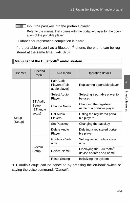
3-3. Using the Bluetooth® audio system
3
Interior features
Input the passkey into the portable player.Refer to the manual that comes with the portable player for the oper-ation of the portable player.
Guidance for registration completion is heard.
If the portable player has a Bluetooth® phone, the phone can be reg-istered at the same time. (→P. 370)
Menu list of the Bluetooth® audio system
“BT Audio Setup” can be canceled by pressing the on-hook switch orsaying the voice command, “Cancel”.
First menu Second menu Third menu Operation details
Setup (Setup)
BT Audio Setup (BT audio setup)
Pair Audio Players (Pair audio player)
Registering a portable player
Select Audio Player
Selecting a portable player to be used
Change Name Changing the registered name of a portable player
List Audio Players
Listing the registered porta-ble players
Set Passkey Changing the passkey
Delete Audio Player
Deleting a registered porta-ble player
System Setup
Guidance Vol-ume
Setting voice guidance vol-ume
Device Name Displaying the Bluetooth® device address and name
Reset Setting Initializing the system
STEP 6
353

3-3. Using the Bluetooth® audio system
■When using a voice commandFor numbers, say a combination of single digits from zero to nine.
Say the command correctly and clearly.
■Situations where the system may not recognize your voice●When driving on rough roads
●When driving at high speeds
●When air is blowing out of the vents onto the microphone
●When the air conditioning fan emits a loud noise
■Operations that cannot be performed while driving
●Operating the system with
●Registering a portable player to the system
■Changing the passkey→P. 360
354

®
3
Interior features
3-3. Using the Bluetooth audio system
Operating a Bluetooth® enabled portable player
Selecting an album
Press “∨” or “∧” on .
Selecting tracks
Press “∧” or “∨” on .
Playing and pausing tracks
Press .
VolumePower
Playback/pause
Displaying text messages
Selector knob
Selecting tracksFast-forwardingand reversing
Playback
355

3-3. Using the Bluetooth® audio system
Fast-forwarding and reversing tracks
Press and hold “∧” or “∨” on .
Switching the display
Press .
Each time is pressed, the display changes in the following order: Track title → Track title/Artist name → Track title/Album name → Tracktitle/Elapsed time
Using the steering wheel audio switches
→P. 341
■Bluetooth® audio system functionsDepending on the portable player that is connected to the system, certainfunctions may not be available.
356
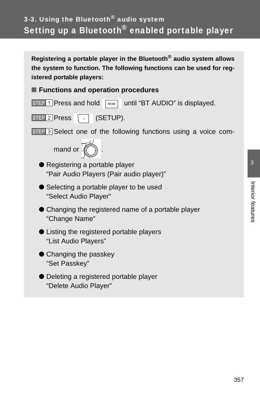
®
3
Interior features
3-3. Using the Bluetooth audio system
Setting up a Bluetooth® enabled portable player
Registering a portable player in the Bluetooth® audio system allowsthe system to function. The following functions can be used for reg-istered portable players:
■ Functions and operation procedures
Press and hold until “BT AUDIO” is displayed.
Press (SETUP).
Select one of the following functions using a voice com-
mand or .
● Registering a portable player “Pair Audio Players (Pair audio player)”
● Selecting a portable player to be used “Select Audio Player”
● Changing the registered name of a portable player“Change Name”
● Listing the registered portable players “List Audio Players”
● Changing the passkey “Set Passkey”
● Deleting a registered portable player “Delete Audio Player”
STEP 1
STEP 2
STEP 3
357

3-3. Using the Bluetooth® audio system
Registering a portable player
Select “Pair Audio Players (Pair audio player)” using a voice com-
mand or , and perform the procedure for registering a portable
player. (→P. 352)
Selecting a portable player to be used
Select “Select Audio Player” using a voice command or
.
Select the portable player to be used by either of the followingmethods, and select “Confirm” using a voice command or
:
a. Press the talk switch and say the name of the desired por-table player.
b. Press the talk switch and say “List audio players”. When thename of the desired portable player is read aloud, press thetalk switch.
STEP 1
STEP 2
358

3-3. Using the Bluetooth® audio system
3
Interior features
Press the talk switch and say “From car” or “From audio”, and
select “Confirm” using a voice command or .
Vehicles with smart key system: If “From car” is selected, the porta-ble player will be automatically connected whenever the “ENGINESTART STOP” switch is in either ACCESSORY or IGNITION ONmode.
Vehicles without smart key system: If “From car” is selected, the por-table player will be automatically connected whenever the engineswitch is in either the “ACC” or “ON” position.
Changing the registered name of a portable player
Select “Change Name” using a voice command or .
Select the name of the portable player to be changed byeither of the following methods, and select “Confirm” using a
voice command or :
a. Press the talk switch and say the name of the desired por-table player.
b. Press the talk switch and say “List audio players”. When thename of the desired portable player is read aloud, press thetalk switch.
Press the talk switch or select “Record Name” using ,
and say the new name.
Select “Confirm” using a voice command or .
STEP 3
STEP 1
STEP 2
STEP 3
STEP 4
359

3-3. Using the Bluetooth® audio system
Listing the registered portable players
Select “List Audio Players” using a voice command or . The
list of registered portable players will be read aloud.When listing is complete, the system returns to “BT Audio Setup”.
Pressing the talk switch while the name of a portable player is beingread aloud selects the portable player, and the following functions willbecome available:
● Selecting a portable player: “Select Audio Player”
● Changing a registered name: “Change Name”
● Deleting a portable player: “Delete Audio Player”
Changing the passkey
Select “Set Passkey” using a voice command or .
Press the talk switch, say a 4 to 8-digit number, and select
“Confirm” using a voice command or .
When the entire number to be registered as a passkey has
been input, press again.
STEP 1
STEP 2
STEP 3
360

3-3. Using the Bluetooth® audio system
3
Interior features
Deleting a registered portable player
Select “Delete Audio Player” using a voice command or
.
Select the portable player to be deleted by either of the follow-ing methods and select “Confirm” using a voice command or
:
a. Press the talk switch and say the name of the desired por-table player.
b. Press the talk switch and say “List audio players”. When thename of the desired portable player is read aloud, press thetalk switch.
If the portable player to be deleted is paired as a Bluetooth® phone,the registration of the mobile phone can be deleted at the same time.A voice guidance instruction to delete a mobile phone is heard.
Select “Confirm” using a voice command or .
■The number of portable players that can be registeredUp to 2 portable players can be registered in the system.
STEP 1
STEP 2
STEP 3
361

®
3-3. Using the Bluetooth audio systemBluetooth® audio system setup
■ System setup items and operation procedures→P. 385
362
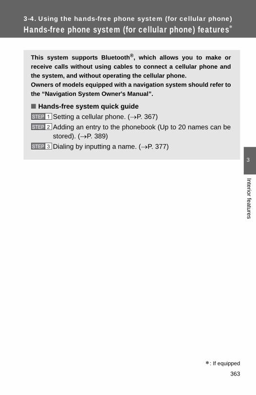
3-4. Using the hands-free phone system (for cellular phone)∗
3
Interior features
Hands-free phone system (for cellular phone) features
This system supports Bluetooth®, which allows you to make orreceive calls without using cables to connect a cellular phone andthe system, and without operating the cellular phone.Owners of models equipped with a navigation system should refer tothe “Navigation System Owner's Manual”.
■ Hands-free system quick guideSetting a cellular phone. (→P. 367)Adding an entry to the phonebook (Up to 20 names can bestored). (→P. 389)Dialing by inputting a name. (→P. 377)
STEP 1
STEP 2
STEP 3
∗: If equipped
363

3-4. Using the hands-free phone system (for cellular phone)
Title Page
Using the hands-free phone system■Operating the system using a voice
command■Using the hands-free phone system for
the first time■Menu list of the hands-free phone
system
P. 367
Making a phone call■Dialing by inputting a number■Dialing by inputting a name■Speed dialing■When receiving a phone call■Transferring a phone call■Using the call history
P. 376
Setting a cellular phone■Registering a cellular phone■Selecting a cellular phone to be used■Changing a registered name■Listing the registered cellular phones■Deleting a cellular phone■Changing the passkey■Turning the hands-free phone
automatic connection on/off
P. 380
Security and system setup■Setting or changing the PIN■Locking or unlocking the phone book■Setting voice guidance volume■ Initialization
P. 385
Using the phone book■Adding a new phone number■Setting speed dials■Changing a registered name■Deleting registered data■Deleting speed dials■Listing the registered data
P. 389
364

3-4. Using the hands-free phone system (for cellular phone)
3
Interior features
■Conditions under which the system will not operate● If using a cellular phone that does not support Bluetooth®
● If the cellular phone is switched off
● If you are outside service range
● If the cellular phone is not connected
● If the cellular phone's battery is low
● If the cellular phone is behind the seat or in the glove box or console box
● If metal is covering or touching the cellular phone
■When transferring ownership of the vehicleBe sure to initialize the system to prevent personal data from being improp-erly accessed.
■Required profiles for the cellular phone●HFP (Hands Free Profile) Ver. 1.0
●OPP (Object Push Profile) Ver. 1.1
■About Bluetooth®
■Certification for the hands-free phone systemFCC ID: ACJ932C5ZZZ035IC ID: 216J-C5ZZZ035MADE IN JAPAN
This device complies with Part 15 of the FCC Rules and RSS-Gen of ICRules. Operation is subject to the following two conditions: (1) this devicemay not cause harmful interference, and (2) this device must accept anyinterference received, including interference that may cause undesired oper-ation.
Bluetooth is a registered trademark ofBluetooth SIG. Inc.
365

3-4. Using the hands-free phone system (for cellular phone)
CAUTION
■FCC WARNINGChanges or modifications not expressly approved by the party responsiblefor compliance could void the user's authority to operate the equipment.
Radio Frequency Radiation Exposure. This equipment complies with FCC/IC radiation exposure limits set forth for uncontrolled equipment and meetsthe FCC radio frequency (RF) Exposure Guidelines in Supplement C toOET65 and RSS-102 of the IC radio frequency (RF) Exposure rules. Thisequipment has very low levels of RF energy that it deemed to comply with-out maximum permissive exposure evaluation (MPE). But it is desirable thatit should be installed and operated with at least 7.9 in. (20 cm) and morebetween the radiator and person’s body (excluding extremities: hands,wrists, feet and ankles).
This transmitter must not be co-located or operated in conjunction with anyother antenna or transmitter.
■Caution while drivingDo not use a cellular phone, or connect the Bluetooth® phone.
NOTICE
■To prevent damage to a cellular phoneDo not leave a cellular phone in the vehicle. The temperature inside maybecome high resulting in damage to the phone.
366

3
Interior features
3-4. Using the hands-free phone system (for cellular phone)
Using the hands-free phone system∗
■ Audio unitDisplayA message, name, phonenumber, etc. is displayed.
Lower-case characters andspecial characters, such asan umlaut, cannot be dis-played.
Selects speed dialsSelects items such as menuor numberTurn: Selects an itemPress: Inputs the selecteditemBluetooth® connection con-dition and reception level
If “BT” is not displayed, thehands-free phone systemcannot be used.
∗: If equipped
367
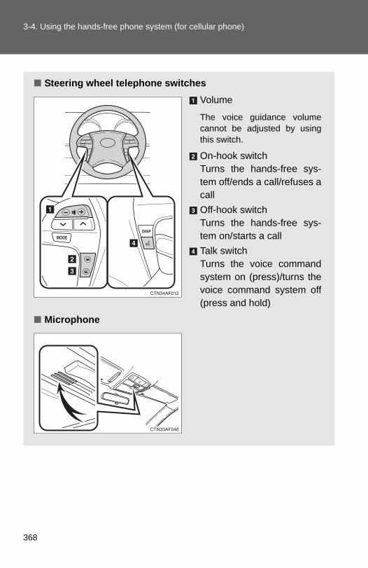
3-4. Using the hands-free phone system (for cellular phone)
■ Steering wheel telephone switchesVolume
The voice guidance volumecannot be adjusted by usingthis switch.
On-hook switch Turns the hands-free sys-tem off/ends a call/refuses acallOff-hook switch Turns the hands-free sys-tem on/starts a callTalk switchTurns the voice commandsystem on (press)/turns thevoice command system off(press and hold)
■ Microphone
368

3-4. Using the hands-free phone system (for cellular phone)
3
Interior features
Operating the system using a voice command
By following voice guidance instructions output from the speaker,voice commands enable the operation of the hands-free phone sys-
tem without the need to check the display or operate .
■ Operation procedure when using a voice commandPress the talk switch and follow voice guidance instructions.
■ Auxiliary commands when using a voice commandThe following auxiliary commands can be used when operating thesystem using a voice command:
“Cancel”: Exits the hands-free phone system“Repeat”: Repeats the previous voice guidance instruction“Go back”: Returns to the previous procedure“Help”: Reads aloud the function summary if a help comment isregistered for the selected function
369

3-4. Using the hands-free phone system (for cellular phone)
Using the hands-free phone system for the first time
Before using the hands-free phone system, it is necessary to registera cellular phone in the system. The phone registration mode will beentered automatically when starting the system with no cellularphone registered. Follow the procedure below to register a cellularphone:
Press the off-hook switch or the talk switch.The introductory guidance and phone name registration instructionsare heard.
Select “Pair Phone” using a voice command or .
Register a phone name by either of the following methods.
a. Select “Record Name” using , and say a name to be
registered.b. Press the talk switch and say a name to be registered.
Voice guidance instruction to confirm the input is heard.
Select “Confirm” using a voice command or .
STEP 1
STEP 2
STEP 3
STEP 4
370

3-4. Using the hands-free phone system (for cellular phone)
3
Interior features
Registration to the hands-free phone system only
Select “Phone Only” using a voice command or .
Registration to the hands-free phone system and Bluetooth®
audio system at the same time
Select “Int. Audio (Internal audio)” using a voice command or
.
Select “Confirm” using a voice command or .
A passkey is displayed and heard, and a voice guidance instructionfor inputting the passkey into the cellular phone is heard.
Input the passkey into the cellular phone.Refer to the manual that comes with the cellular phone for the oper-ation of the phone.
Guidance for registration completion is heard.
STEP 5
STEP 5
STEP 6
STEP 7
371
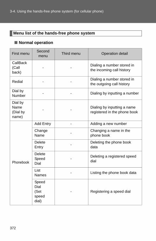
3-4. Using the hands-free phone system (for cellular phone)
Menu list of the hands-free phone system
■ Normal operation
First menu Second menu Third menu Operation detail
CallBack(Call back)
- - Dialing a number stored in the incoming call history
Redial - - Dialing a number stored in the outgoing call history
Dial by Number - - Dialing by inputting a number
Dial by Name (Dial by name)
- - Dialing by inputting a name registered in the phone book
Phonebook
Add Entry - Adding a new number
Change Name - Changing a name in the
phone book
Delete Entry - Deleting the phone book
data
Delete Speed Dial
- Deleting a registered speed dial
List Names - Listing the phone book data
Speed Dial (Set speed dial)
- Registering a speed dial
372
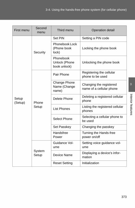
3-4. Using the hands-free phone system (for cellular phone)
3
Interior features
Setup (Setup)
Security
Set PIN Setting a PIN code
Phonebook Lock (Phone book lock)
Locking the phone book
Phonebook Unlock (Phone book unlock)
Unlocking the phone book
Phone Setup
Pair Phone Registering the cellular phone to be used
Change Phone Name (Change name)
Changing the registered name of a cellular phone
Delete Phone Deleting a registered cellular phone
List Phones Listing the registered cellular phones
Select Phone Selecting a cellular phone to be used
Set Passkey Changing the passkey
Handsfree Power
Turning the Hands-free power on/off
System Setup
Guidance Vol-ume
Setting voice guidance vol-ume
Device Name Displaying a device’s infor-mation
Reset Setting Initialization
First menu Second menu Third menu Operation detail
373

3-4. Using the hands-free phone system (for cellular phone)
■ Using a short cut key
First menu Second menu Operation detail
Dial “XXX (name)” - Dialing a number registered in the phone book
Dial “XXX (number)” - Dialing the input numbers
Phone book add entry - Adding a new number
Phone book change name -
Changing the name of a phone number in the phone book
Phone book delete entry - Deleting phone book data
Phone book set speed dial - Registering a speed dial
Phone book delete speed dial - Deleting a speed dial
Phone book List names - Listing the phone book data
374

3-4. Using the hands-free phone system (for cellular phone)
3
Interior features
■Automatic volume adjustmentWhen vehicle speed reaches 50 mph (80 km/h) or more, the volume auto-matically increases. The volume returns to the previous volume setting whenvehicle speed drops to 43 mph (70 km/h) or less.
■When using a voice commandFor numbers, say a combination of single digits from zero to nine, # (pound),∗ (star), and + (plus).
Say the command correctly and clearly.
■Situations that the system may not recognize your voice●When driving on a rough road
●When driving at high speeds
●When air is blowing out of the vents onto the microphone
●When the air conditioning fan emits a loud noise
■Operations that cannot be performed while driving
●Operating the system with
●Registering a cellular phone to the system
■Changing the passkey→P. 383
375

3-4. Using the hands-free phone system (for cellular phone)
Making a phone call
Dialing by inputting a number
Press the talk switch and say “Dial by number”.Press the talk switch and say the phone number.
■ Making a phone call● Dialing by inputting a number
“Dial by Number”
● Dialing by inputting a name“Dial by Name (Dial by name)”
● Speed dialing
● Dialing a number stored in the outgoing history“Redial”
● Dialing a number stored in the incoming history“CallBack (Callback)”
■ Receiving a phone call● Answering the phone
● Refusing the call
■ Transferring a phone call■ Using the call history
● Dialing
● Storing data in the phone book
● Deleting
STEP 1
STEP 2
376

3-4. Using the hands-free phone system (for cellular phone)
3
Interior features
Dial by one of the following methods:a. Press the off-hook switch.b. Press the talk switch and say “Dial”.
c. Select “Dial” using .
Dialing by inputting a name
Press the talk switch and say “Dial by name”.Select a registered name to be input by either of the followingmethods:a. Press the talk switch and say a registered name.b. Press the talk switch and say “List names”. Press the talk
switch while the desired name is being read aloud.Dial by one of the following methods:a. Press the off-hook switch.b. Press the talk switch and say “Dial”.
c. Select “Dial” using .
Speed dialing
Press the off-hook switch.Press the preset button to which the desired number is regis-tered.Press the off-hook switch.
STEP 3
STEP 1
STEP 2
STEP 3
STEP 1
STEP 2
STEP 3
377

3-4. Using the hands-free phone system (for cellular phone)
When receiving a phone call
■ Answering a phone callPress the off-hook switch.
■ Refusing a phone callPress the on-hook switch.
Transferring a phone call
A call can be transferred between the cellular phone and systemwhile dialing, receiving a call, or during a call. Use one of the follow-ing methods:
a. Operate the cellular phone.
Refer to the manual that comes with the cellular phone for the oper-ation of the phone.
b. Press the off-hook switch*1.
c. Press the talk switch and say “Call transfer”*2.*1: This operation can be performed only when transferring a call
from the cellular phone to the system during a call.*2: While the vehicle is in motion, a call cannot be transferred from
the system to the cellular phone. Also, this operation is invalidwhile dialing or receiving a call.
Using the call history
Follow the procedure below to use a number stored in the call history:
Press the talk switch and say “Redial” (when using a numberstored in the outgoing call history) or “Callback” (when using anumber stored in the incoming call history).
STEP 1
378

3-4. Using the hands-free phone system (for cellular phone)
3
Interior features
Select the number by either of the following methods:a. Say “Previous” or “Go back” until the desired number is dis-
played.
b. Select the desired number using .
The following operations can be performed:
Dialing: Press the off-hook switch or select “Dial” using a voice
command or .
Storing the number in the phone book: Select “Store” using a voice
command or .
Deleting: Select “Delete” using a voice command or .
■Call historyUp to 5 numbers can be stored in each of the outgoing and incoming call his-tory memories.
■When talking on the phone●Do not talk at the same time as the other party.
●Keep the volume of the incoming voice down. Otherwise, voice echo willincrease.
STEP 2
379

3-4. Using the hands-free phone system (for cellular phone)
Setting a cellular phone
Registering a cellular phone
Select “Pair Phone” using a voice command or , and perform
the procedure for registering a cellular phone. (→P. 370)
Registering a cellular phone in the hands-free phone system allowsthe system to function. The following functions can be used for reg-istered cellular phones:
■ Functions and operation proceduresTo enter the menu for each function, follow the steps below using a
voice command or :
● Registering a cellular phone 1. “Setup (Setup)” → 2. “Phone Setup” → 3. “Pair Phone”
● Selecting the cellular phone to be used 1. “Setup (Setup)” → 2. “Phone Setup” → 3. “Select Phone”
● Changing a registered name 1. “Setup (Setup)” → 2. “Phone Setup” → 3. “Change PhoneName (Change name)”
● Listing the registered cellular phones 1. “Setup (Setup)” → 2. “Phone Setup” → 3. “List Phones”
● Deleting a cellular phone 1. “Setup (Setup)” → 2. “Phone Setup” → 3. “Delete Phone”
● Changing the passkey 1. “Setup (Setup)” → 2. “Phone Setup” → 3. “Set Passkey”
● Turning the hands-free phone automatic connection on/off1. “Setup (Setup)” → 2. “Phone Setup” → 3. “HandsfreePower”
380

3-4. Using the hands-free phone system (for cellular phone)
3
Interior features
Selecting a cellular phone to be used
Select “Select Phone” using a voice command or .
Pattern A
Select a cellular phone to be used by either of the followingmethods, and select “Confirm” using a voice command or
:
a. Press the talk switch and say the desired phone name.b. Press the talk switch and say “List phones”. While the name
of the desired cellular phone is being read aloud, press thetalk switch.
Pattern BSelect a cellular phone to be used using .
Changing a registered name
Select “Change Phone Name (Change name)” using a voice
command or .
Select the name of the cellular phone to be changed by eitherof the following methods:a. Press the talk switch and say the desired phone name, and
select “Confirm” using a voice command or .
b. Press the talk switch and say “List phones”. While thedesired phone name is being read aloud, press the talkswitch.
c. Select the desired phone name using .
STEP 1
STEP 2
STEP 2
STEP 1
STEP 2
381
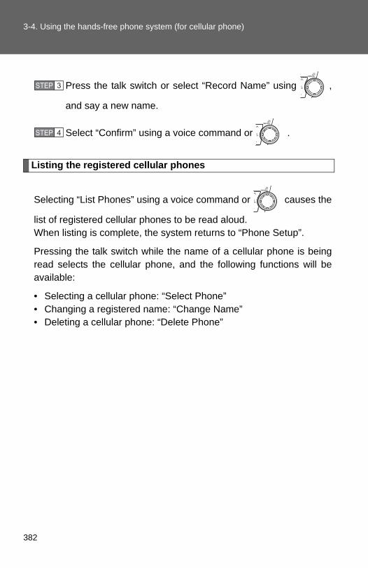
3-4. Using the hands-free phone system (for cellular phone)
Press the talk switch or select “Record Name” using ,
and say a new name.
Select “Confirm” using a voice command or .
Listing the registered cellular phones
Selecting “List Phones” using a voice command or causes the
list of registered cellular phones to be read aloud.When listing is complete, the system returns to “Phone Setup”.
Pressing the talk switch while the name of a cellular phone is beingread selects the cellular phone, and the following functions will beavailable:
• Selecting a cellular phone: “Select Phone”• Changing a registered name: “Change Name”• Deleting a cellular phone: “Delete Phone”
STEP 3
STEP 4
382

3-4. Using the hands-free phone system (for cellular phone)
3
Interior features
Deleting a cellular phone
Select “Delete Phone” using a voice command or .
Select a cellular phone to be deleted by either of the followingmethods and select “Confirm” using a voice command or
:
a. Press the talk switch and say the name of the desired cellu-lar phone.
b. Press the talk switch and say “List phones”. While the nameof the desired cellular phone is being read aloud, press thetalk switch.
Changing the passkey
Select “Set Passkey” using a voice command or .
Press the talk switch, say a 4 to 8-digit number, and select
“Confirm” using a voice command or .
The number should be input 1 digit at a time.
When the entire number to be registered as a passkey has
been input, press again.
STEP 1
STEP 2
STEP 1
STEP 2
STEP 3
383

3-4. Using the hands-free phone system (for cellular phone)
Turning the hands-free phone automatic connection on/off
■ Turning off the automatic connection
Select “Handsfree Power” using a voice command or .
Select “Turn off” using a voice command or .
■ Turning on the automatic connection
Select “Handsfree Power” using a voice command or .
Select “Turn on” using a voice command or .
■The number of cellular phones that can be registeredUp to 6 cellular phones can be registered in the system.
STEP 1
STEP 2
STEP 1
STEP 2
384

3
Interior features
3-4. Using the hands-free phone system (for cellular phone)
Security and system setup
Setting or changing the PIN
■ Setting a PIN
Select “Set PIN” using a voice command or .
Enter a PIN using a voice command or .
When using , input the code 1 digit at a time.
To enter the menu of each setting, follow the steps below:
■ Security setting items and operation procedure● Setting or changing the PIN (Personal Identification Number)
1. “Setup (Setup)” → 2. “Security” → 3. “Set PIN”
● Locking the phone book 1. “Setup (Setup)” → 2. “Security” → 3. “Phonebook Lock(Phone book lock)”
● Unlocking the phone book 1. “Setup (Setup)” → 2. “Security” → 3. “Phonebook Unlock(Phone book unlock)”
■ System setup items and operation procedure● Setting voice guidance volume
1. “Setup (Setup)” → 2. “System Setup” → 3. “Guidance Vol-ume”
● Initialization 1. “Setup (Setup)” → 2. “System Setup” → 3. “Reset Settings”
can only be used for system setup operation.
STEP 1
STEP 2
385

3-4. Using the hands-free phone system (for cellular phone)
■ Changing the PIN
Select “Set PIN” using a voice command or .
Enter the registered PIN using a voice command or .
Enter a new PIN using a voice command or .
When using , input the code 1 digit at a time.
Locking or unlocking the phone book
Select “Phonebook Lock (Phone book lock)” or “PhonebookUnlock (Phone book unlock)” using a voice command or
.
Input the PIN by either of the following methods and select
“Confirm” using a voice command or :
a. Press the talk switch and say the registered PIN.
b. Input a new PIN using .
STEP 1
STEP 2
STEP 3
STEP 1
STEP 2
386

3-4. Using the hands-free phone system (for cellular phone)
3
Interior features
Setting voice guidance volume
Select “Guidance Volume” using .
Change the voice guidance volume.
To decrease the volume: Turn counterclockwise.
To increase the volume: Turn clockwise.
Initialization
Select “Reset Settings” and then “Confirm” using .
Select “Confirm” using .
STEP 1
STEP 2
STEP 1
STEP 2
387

3-4. Using the hands-free phone system (for cellular phone)
■ Initialization●The following data in the system can be initialized:
• Phone book• Outgoing and incoming call history• Speed dials• Registered cellular phone data• Security code
●Once the initialization has been completed, the data cannot be restoredto its original state.
■When the phone book is lockedThe following functions cannot be used:
●Dialing by inputting a name
●Speed dialing
●Dialing a number stored in the call history
●Using the phone book
388

3
Interior features
3-4. Using the hands-free phone system (for cellular phone)
Using the phone book
Adding a new phone number
The following methods can be used to add a new phone number:
● Inputting a phone number by using a voice command
● Transferring data from the cellular phone
● Inputting a phone number using
● Selecting a phone number from the outgoing or incoming call his-tory
■ Adding procedure
Select “Add Entry” using a voice command or .
To enter the menu of each setting, follow the steps below:
● Adding a new phone number 1. “Phonebook” → 2. “Add Entry”
● Setting speed dial 1. “Phonebook” → 2. “Speed Dial (Set speed dial)”
● Changing a registered name 1. “Phonebook” → 2. “Change Name”
● Deleting registered data 1. “Phonebook” → 2. “Delete Entry”
● Deleting speed dial 1. “Phonebook” → 2. “Delete Speed Dial”
● Listing the registered data 1. “Phonebook” → 2. “List Names”
STEP 1
389

3-4. Using the hands-free phone system (for cellular phone)
Use one of the following methods to input a telephone num-ber:
Inputting a telephone number using a voice commandSTEP2-1 Select “By Voice (By voice)” using a voice command
or .
STEP2-2 Press the talk switch, say the desired number, andselect “Confirm” using a voice command.
Transferring data from the cellular phoneSTEP2-1 Select “By Phone” and then “Confirm” using a voice
command or .
STEP2-2 Transfer the data from the cellular phone.Refer to the manual that comes with the cellular phone forthe details of transferring data.
STEP2-3 Select the data to be registered by either of the fol-lowing methods:a. Say “Previous” or “Next” until the desired data is
displayed, and select “Confirm” using a voicecommand.
b. Select the desired data using .
STEP 2
390

3-4. Using the hands-free phone system (for cellular phone)
3
Interior features
Inputting a phone number using
STEP2-1 Select “Manual Input” using .
STEP2-2 Input a phone number using , and press
once again.
Input the phone number 1 digit at a time.
Selecting a phone number from outgoing or incoming call historySTEP2-1 Select “Call History” using a voice command or
.
STEP2-2 Select “Outgoing Call History (Outgoing)” or “Incom-ing Call History (Incoming)” using a voice command
or .
STEP2-3 Select the data to be registered by either of the fol-lowing methods:a. Say “Previous” or “Go back” until the desired
data is displayed, and select “Confirm” using avoice command.
b. Select the desired data using .
391
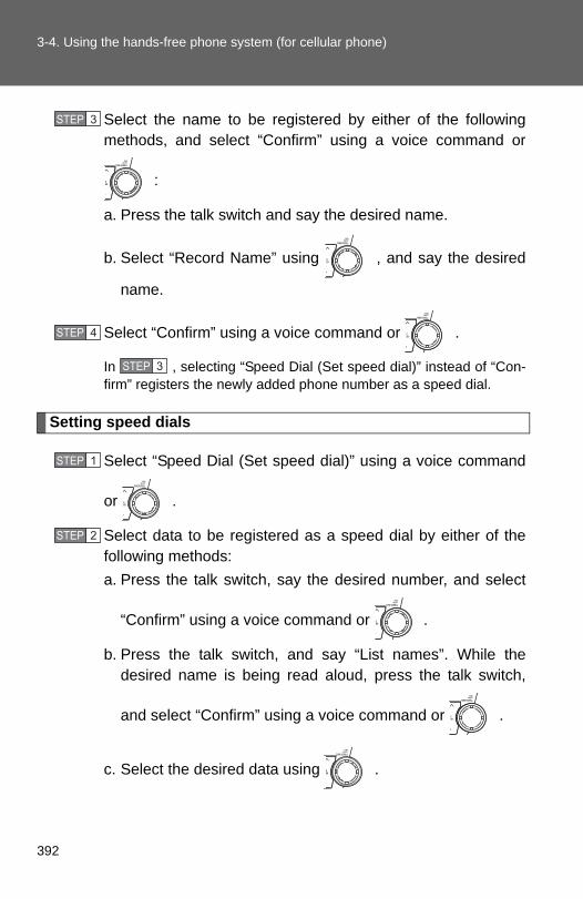
3-4. Using the hands-free phone system (for cellular phone)
Select the name to be registered by either of the followingmethods, and select “Confirm” using a voice command or
:
a. Press the talk switch and say the desired name.
b. Select “Record Name” using , and say the desired
name.
Select “Confirm” using a voice command or .
In , selecting “Speed Dial (Set speed dial)” instead of “Con-firm” registers the newly added phone number as a speed dial.
Setting speed dials
Select “Speed Dial (Set speed dial)” using a voice command
or .
Select data to be registered as a speed dial by either of thefollowing methods:a. Press the talk switch, say the desired number, and select
“Confirm” using a voice command or .
b. Press the talk switch, and say “List names”. While thedesired name is being read aloud, press the talk switch,
and select “Confirm” using a voice command or .
c. Select the desired data using .
STEP 3
STEP 4
STEP 3
STEP 1
STEP 2
392

3-4. Using the hands-free phone system (for cellular phone)
3
Interior features
Select a desired preset button, and register the data intospeed dial by either of the following methods:a. Press the desired preset button, and select “Confirm” using
a voice command or .
b. Press and hold the desired preset button.
Changing a registered name
Select “Change Name” using a voice command or .
Select a name to be changed by either of the following meth-ods:a. Press the talk switch, say the desired name, and select
“Confirm” using a voice command or .
b. Press the talk switch, and say “List names”. While thedesired name is being read aloud, press the talk switch,
and select “Confirm” using a voice command or .
c. Select the desired name using .
Select “Record Name” with or the talk switch.
Say a new name, and select “Confirm” using a voice com-
mand or .
STEP 3
STEP 1
STEP 2
STEP 3
STEP 4
393

3-4. Using the hands-free phone system (for cellular phone)
Deleting registered data
Select “Delete Entry” using a voice command or .
Select the data to be deleted by either of the following meth-
ods, and select “Confirm” using a voice command or :
a. Press the talk switch, and say the name of the desiredphone number to be deleted.
b. Press the talk switch, say “List phones”. While the name ofthe desired phone number is being read aloud, press thetalk switch.
Deleting speed dials
Select “Delete Speed Dial” using a voice command or .
Press the preset button in which the desired speed dial is reg-istered, and select “Confirm” using a voice command or
.
STEP 1
STEP 2
STEP 1
STEP 2
394

3-4. Using the hands-free phone system (for cellular phone)
3
Interior features
Listing the registered data
Selecting “List names” using a voice command causes a list of theregistered data to be read aloud.
When listing is complete, the system returns to “Phonebook”.Pressing the talk switch while the desired data is being read aloudselects the data, and the following function will become available.
• Dialing: “Dial”• Changing a registered name: “Change Name”• Deleting an entry: “Delete Entry”• Setting a speed dial: “Speed Dial (Set speed dial)”
■Limitation of number of digitsA phone number that exceeds 24 digits cannot be registered.
395

3-5. Using the interior lights
Interior lights list
Your Toyota is equipped with an illuminated entry system to assist inentering the vehicle. Owing to the function of the system, the lightsshown in the following illustration automatically turn on/off accord-ing to the presence of the electronic key (vehicles with smart keysystem), whether the doors are locked/unlocked, whether the doorsor glass hatch (if equipped) are opened/closed, the “ENGINE STARTSTOP” switch mode and engine switch position.
Outer foot lights (vehicles with smart key system)Personal/interior lights (→P. 397)Engine switch light (vehicles without smart key system)Front door courtesy lightPersonal/interior light or interior light (→P. 397, 398)Interior light (→P. 398)
396

3-5. Using the interior lights
3
Interior features
Personal/interior light main switch and personal/interior lights
Personal/interior light main switch
“OFF”
The personal/interior lights andinterior light can be individuallyturned on or off.
Door position
The personal/interior lights andinterior light come on when a dooror the glass hatch (if equipped) isopened. They turn off when thedoors and glass hatch are closed.
On
The personal/interior lights andinterior light cannot be individuallyturned off.
Personal/interior lights
Front
On/off
The illuminated entry system isactivated even if the light isturned off when the personal/inte-rior light main switch is in doorposition.
397

3-5. Using the interior lights
Personal/interior lights and interior light
Center (if equipped)
On/off
The illuminated entry system isactivated even if the light isturned off when the personal/inte-rior light main switch is in doorposition.
Interior light
OnOff
The illuminated entry system isactivated even if the light isturned off when the personal/inte-rior light main switch is in doorposition.
RearCenter (if equipped)
■To prevent battery dischargeIf the lights remain on when the door is not fully closed and the personal/inte-rior light main switch is in the door position, the lights will go off automaticallyafter 20 minutes.
■Customization that can be configured at Toyota dealerSettings (e.g. The time elapsed before lights turn off) can be changed. (Customizable features →P. 602)
398

3-6. Using the storage features
3
Interior features
List of storage features
Auxiliary boxesOverhead consoleGlove boxBottle holdersCup holdersSide tableConsole box
399

3-6. Using the storage features
Glove box
Glove box
Unlock with the master key(vehicles without smart keysystem) or mechanical key(vehicles with smart key sys-tem)Lock with the master key(vehicles without smart keysystem) or mechanical key(vehicles with smart key sys-tem)Open (pull lever)
CAUTION
■ Items that should not be left in the storage spacesDo not leave glasses, lighters or spray cans in the storage spaces, as thismay cause the following when cabin temperature becomes high:
●Glasses may be deformed by heat or cracked if they come into contactwith other stored items.
●Lighters or spray cans may explode. If they come into contact with otherstored items, the lighter may catch fire or the spray can may release gas,causing a fire hazard.
■Power back door main switch (vehicles with power back door)The power back door main switch is located in the glove box. (→P. 62)
CAUTION
■Caution while drivingKeep the glove box closed.Injuries may result in the event of an accident or sudden braking.
400

3-6. Using the storage features
3
Interior features
Console box
Console box
Upper
Pull up the knob to release thelock. Lift the lid.
Lower
Push down the lever.
CAUTION
■Caution while drivingKeep the console box closed.Injuries may result in the event of an accident or sudden braking.
401

3-6. Using the storage features
Overhead console
Overhead console
The overhead console is useful for temporarily storing sunglassesand similar small items.
Press in the lid.
CAUTION
■Caution while drivingDo not leave the overhead console open while driving.Items stored in it may fall out and cause injury.
■Size of stored itemsDo not put large items in the overhead console. The overhead console may not be able to be shut from the conversation mir-ror position.
■Maximum storage weightDo not place any object heavier than 0.4 lb. (200 g) in it. The console maybe opened and cause injury.
402

3-6. Using the storage features
3
Interior features
Cup holders
Cup holders
Front (type A)
Front (type B)
Lift the lid.
Console box
Pull out the cup holder.
403

3-6. Using the storage features
Cup holders
Side table
Install the side table before usingthe cup holder. (→P. 410)
Removing the adapters changesthe size. (→P. 405)
Rear
Removing the adapters changesthe size. (→P. 405)
404

3-6. Using the storage features
3
Interior features
Cup holders
■Adjusting size of the cup holder (front [type B], side table and rear)Front (type B)
Side table
Rear
Remove the separator.
The separator may be removed for clean-ing.
Remove the adapter.
Remove the adapter.
405

3-6. Using the storage features
Cup holders
CAUTION
■ Items unsuitable for the cup holderDo not place anything other than cups or beverage cans in the cup holders.Even when the lid is closed, items must not be stored in the cup holders.Other items may be thrown out of the holders in the event of an accident orsudden braking and cause injury. If possible, cover hot drinks to preventburns.
■When not in useFront (type B) and console box cup holders: Keep the cup holders closed.Injuries may result in the event of an accident or sudden braking.
406

3-6. Using the storage features
3
Interior features
Bottle holders
Bottle holders
Front
Rear
CAUTION
■ Items unsuitable for the bottle holderDo not place anything other than a bottle in the bottle holders.Other items may be thrown out of the holders in the event of an accident orsudden braking and cause injury.
NOTICE
■When stowing a bottlePut the cap on before stowing a bottle. Do not place open bottles in the bot-tle holders. The contents may spill.
407

3-6. Using the storage features
Auxiliary boxes
Auxiliary boxes
Type A
Pull up the lever.
Type B (if equipped)
Lift the lid.
408

3-6. Using the storage features
3
Interior features
Auxiliary boxes
Type C
Lift the lid.
■Auxiliary box (type C)The side table can be installed. (→P. 410)
CAUTION
■Caution while drivingKeep the auxiliary boxes closed.Injuries may result in the event of an accident or sudden braking.
409

3-6. Using the storage features
Side table
Side table
■ Installing the side tableTake out the side table from theconsole box.
Remove the second center seat. (→P. 82)
Engage the front pins of theside table with the hooks.Push down on the side table toengage the rear pin locks.
■ Removing the side tableTake out the second center seatfrom the console box.
STEP 1
STEP 2
STEP 3
STEP 1
410

3-6. Using the storage features
3
Interior features
Side table
Pull the lock release lever toremove the side table.
Stow the side table in the con-sole box.
Push down on the end to engagethe pins in the holes and closethe console box door.
Make sure that the side table issecurely locked in position.
STEP 2
STEP 3
STEP 4
CAUTION
■Caution while drivingKeep the console box closed.Injuries may result in the event of an accident or sudden braking.
411

3-7. Other interior features
Sun visors
Forward position Flip down.Side position Flip down, unhook, andswing to the side.Side extenderPlace in side position thenslide backwards.
412

3
Interior features
3-7. Other interior features
Vanity mirrors
NOTICE
■To prevent the battery from being discharged (vehicles with vanity mir-ror light)Do not leave the vanity lights on for extended periods while the engine isstopped.
Slide the cover.
The light turns on when thecover is opened. (Vehicles withvanity mirror light)
413
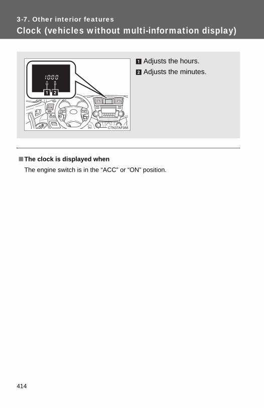
3-7. Other interior features
Clock (vehicles without multi-information display)
■The clock is displayed whenThe engine switch is in the “ACC” or “ON” position.
Adjusts the hours.Adjusts the minutes.
414

3
Interior features
3-7. Other interior features
Conversation mirror
■To use the overhead console from the conversation mirror stateFully close the lid, then open it again. (→P. 402)
Press in the lid.Push the lid back up halfway.
415

3-7. Other interior features
Power outlets
The power outlet can be used for the following components.
12 V: Accessories that run on less than 10 A.120 VAC: Accessories that use less than 100 W.
■ 12 VType A (vehicles with seat heater)
Type B (vehicles without seat heater)
416

3-7. Other interior features
3
Interior features
Type C
Type D
■ 120 VAC (vehicles with rear entertainment system)
417

3-7. Other interior features
■The power outlet can be used when12 V
Vehicles without smart key system:The engine switch is in the “ACC” or “ON” position.
Vehicles with smart key system:The “ENGINE START STOP” switch is in ACCESSORY or IGNITION ONmode.
120 VACVehicles without smart key system:The engine switch is in the “ON” position.
Vehicles with smart key system:The “ENGINE START STOP” switch is in IGNITION ON mode.
418

3-7. Other interior features
3
Interior features
NOTICE
■To avoid damaging the power outletClose the power outlet lid when the power outlet is not in use.Foreign objects or liquids that enter the power outlet may cause a short cir-cuit.
■To prevent the fuse from being blown12 V
Do not use an accessory that uses more than 12 V 10 A.
120 VAC
Do not use a 120 VAC appliance that requires more than 100 W.
If a 120 VAC appliance that consumes more than 100 W is used, the pro-tection circuit will cut the power supply.
■To prevent the battery dischargeDo not use the power outlet longer than necessary when the engine is off.
■Appliances that may not operate properly (120 VAC)The following 120 VAC appliances may not operate properly even if theirpower consumption is under 100 W.
●Appliances with high initial peak wattage
●Measuring devices that process precise data
●Other appliances that require an extremely stable power supply
419

3-7. Other interior features
Seat heaters∗
■The seat heaters can be used whenVehicles without smart key system
The engine switch is in the “ON” position.
Vehicles with smart key system
The “ENGINE START STOP” switch is in IGNITION ON mode.
■When not in useTurn the knob fully counterclockwise. The indicator light turns off.Press the knob into the recessed position.
Pops the knob outOn
The indicator light comes on.
Adjusts the seat tempera-ture
The further you turn the knobclockwise, the warmer the seatbecomes.
Front passenger's seat
Driver's seat
∗: If equipped
420

3-7. Other interior features
3
Interior features
CAUTION
■Burns●Use caution when seating the following persons in a seat with the seat
heater on to avoid the possibility of burns:
• Babies, small children, the elderly, the sick and the disabled• Persons with sensitive skin• Persons who are fatigued• Persons who have taken alcohol or drugs that induce sleep (sleeping
drugs, cold remedies, etc.)●Do not cover the seat with anything when using the seat heater.
Using the seat heater with a blanket or cushion increases the temperatureof the seat and may lead to overheating.
NOTICE
■To prevent seat heater damageDo not put unevenly weighted objects on the seat and do not stick sharpobjects (needles, nails, etc.) into the seat.
■To prevent battery dischargeTurn the switches off when the engine is not running.
421

3-7. Other interior features
Armrests
NOTICE
■To prevent damage to the armrestDo not place too much strain on the armrest.
Pull the armrest down for use.
422

3
Interior features
3-7. Other interior features
Floor mat
CAUTION
Observe the following precautions. Failure to do so may cause the driver's floor mat to slip, possibly interferingwith the pedals while driving. An unexpectedly high speed may result or it maybecome difficult to stop the vehicle, leading to a serious accident.■When installing the driver's floor mat
●Do not use floor mats designed for other models or different model yearvehicles, even if they are Toyota Genuine floor mats.
●Only use floor mats designed for the driver's seat.●Always install the floor mat securely using the retaining hooks (clips) pro-
vided.●Do not use two or more floor mats on top of each other.●Do not place the floor mat bottom-side up or upside-down.
■Before driving
Use only floor mats designed specifically for vehicles of the samemodel and model year as your vehicle. Fix them securely in placeonto the carpet.
Fix the floor mat in place usingthe retaining hooks (clips) pro-vided.
The shape of the retaininghooks (clips) and the fixingprocedure of the floor mat foryour vehicle may differ fromthose shown in the illustration.For details, refer to the floormat retention clip installationinstructions supplied with theclips.
●Check that the floor mat is securelyfixed in the correct place with all theprovided retaining hooks (clips). Beespecially careful to perform this checkafter cleaning the floor.
●With the engine stopped and the shiftlever in P, fully depress each pedal tothe floor to make sure it does not inter-fere with the floor mat.
423
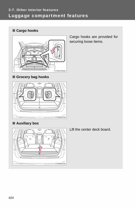
3-7. Other interior features
Luggage compartment features
■ Cargo hooksCargo hooks are provided forsecuring loose items.
■ Grocery bag hooks
■ Auxiliary boxLift the center deck board.
424
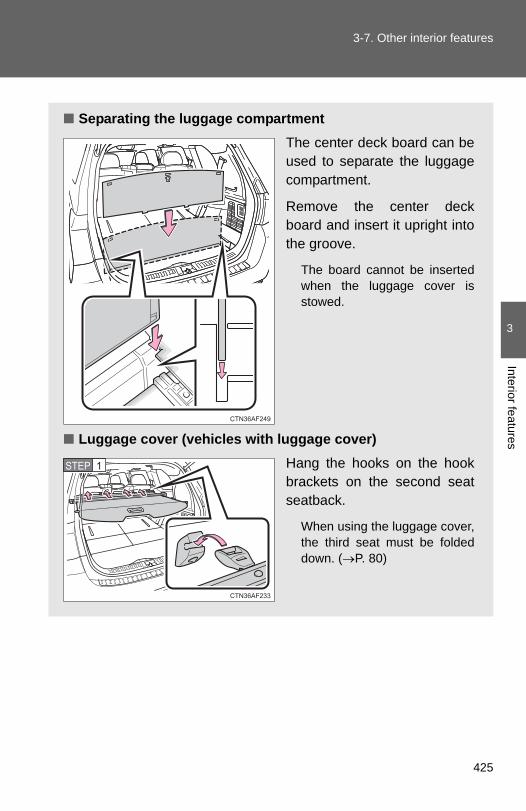
3-7. Other interior features
3
Interior features
■ Separating the luggage compartmentThe center deck board can beused to separate the luggagecompartment.
Remove the center deckboard and insert it upright intothe groove.
The board cannot be insertedwhen the luggage cover isstowed.
■ Luggage cover (vehicles with luggage cover)Hang the hooks on the hookbrackets on the second seatseatback.
When using the luggage cover,the third seat must be foldeddown. (→P. 80)
STEP 1
425
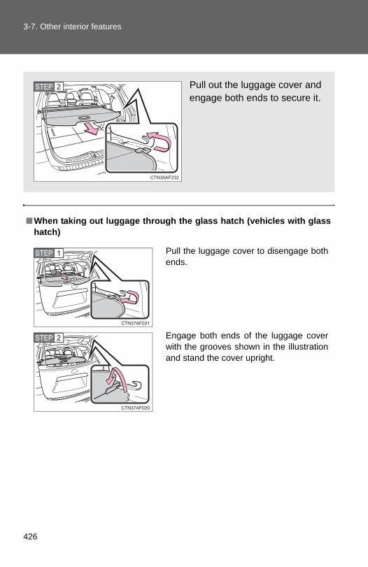
3-7. Other interior features
■When taking out luggage through the glass hatch (vehicles with glasshatch)
Pull out the luggage cover andengage both ends to secure it.
STEP 2
Pull the luggage cover to disengage bothends.
Engage both ends of the luggage coverwith the grooves shown in the illustrationand stand the cover upright.
STEP 1
STEP 2
426

3-7. Other interior features
3
Interior features
■Removing the luggage cover (vehicles with luggage cover)The luggage cover can be removed by following the procedure below.
■Stowing the luggage cover (vehicles with luggage cover)
Detach the hooks.
Push in the left side of the luggagecover while keeping hold of the rightside. Then raise the right side and pullthe luggage cover out.
Remove the side deck boards and openthe center deck board.
Fold the flaps on top of the luggage coverwith the hooks rolled inside.
Place the left end of the luggage cover inthe recess on the left-hand side and thenlower the right end into the recess on theright-hand side.
STEP 1
STEP 2
STEP 3
427
3-7. Other interior features
CAUTION
■When the cargo hooks are not in useTo avoid injury, always return the cargo hooks to their positions when theyare not in use.
■Caution while drivingDo not drive with any of the deck boards opened. Items may fall out andcause injury.
NOTICE
■Shopping bag hook weight capacityDo not hang any object heavier than 4 lb. (2 kg) on shopping bag hooks.
■While drivingDo not drive with the luggage cover standing upright in the grooves as theluggage cover may fall down.
■Before inserting the center deck board into the luggage compartmentMake sure the luggage cover is not stowed.
428

3
Interior features
3-7. Other interior features
Garage door opener∗
The garage door opener (HomeLink® Universal Transceiver) is manufac-tured under license from HomeLink®.
Programming the HomeLink® (for U.S.A. owners)
The HomeLink® compatible transceiver in your vehicle has 3 buttonswhich can be programmed to operate 3 different devices. Refer to theprogramming method below appropriate for the device.
IndicatorButtons
■ Programming the HomeLink®
Point the remote control for thedevice 1 to 3 in. (25 to 75 mm)from the HomeLink® control but-tons.
Keep the indicator light on theHomeLink® in view while pro-gramming.
The garage door opener can be programmed to operate garagedoors, gates, entry doors, door locks, home lighting systems, secu-rity systems, and other devices.
STEP 1
∗: If equipped
429

3-7. Other interior features
Press and hold down one of thebuttons on the HomeLink® andthe button on the transmitter.When the indicator light on theHomeLink® changes from a slowto a rapid flash within 20 sec-onds, you can release both but-tons.
Test the operation of theHomeLink® by pressing thenewly programmed button.
If programming a garage dooropener, check to see if the garagedoor opens and closes. If thegarage door does not operate,see if your garage transmitter isof the Rolling Code type. Pressand hold the programmedHomeLink® button. The garagedoor has the rolling code featureif the indicator light (on theHomeLink®) flashes rapidly for 2seconds and then remains lit. Ifyour transmitter is the RollingCode type, proceed to the head-ing “Programming a rolling codesystem”.
Repeat the steps above to program another device for each ofthe remaining HomeLink® buttons.
STEP 2
STEP 3
STEP 4
430

3-7. Other interior features
3
Interior features
■ Programming a Rolling Code system (for U.S.A. owners)If your device is Rolling Code equipped, follow the steps under theheading “Programming the HomeLink®” before proceeding withthe steps listed below.
Locate the learn button on the ceiling mounted garage dooropener motor. The exact location and color of the button mayvary by brand of garage door opener.Refer to the operation manual supplied with the garage door openerfor the location of the learn button.
Press the learn button.Following this step, you have 30 seconds in which to initiate step 3below.
Press and release the vehicle’s programmed HomeLink® but-ton twice. The garage door may open.If the garage door opens, the programming process is complete. Ifthe door does not open, press and release the button a third time.This third press and release will complete the programming processby opening the garage door.
The ceiling mounted garage door opener motor should now recog-nize the HomeLink® transceiver and operate the garage door.
Repeat the steps above to program another rolling code sys-tem for any of the remaining HomeLink® buttons.
■ Programming an entry gate (for U.S.A. owners)/Programmingall devices in the Canadian market
Place your transmitter 1 to 3 in. (25 to 75 mm) away from thesurface of the HomeLink®.Keep the indicator light on the HomeLink® in view while program-ming.
Press and hold the selected HomeLink® button.Repeatedly press and release (cycle) the device’s remotecontrol button for two seconds each until step 4 is complete.When the indicator light on the HomeLink® compatible trans-ceiver starts flashing rapidly, release the buttons.
STEP 1
STEP 2
STEP 3
STEP 4
STEP 1
STEP 2
STEP 3
STEP 4
431

3-7. Other interior features
Test the operation of the HomeLink® by pressing the newlyprogrammed button. Check to see if the gate/device operatescorrectly.Repeat the steps above to program another device for each ofthe remaining HomeLink® buttons.
■ Programming other devicesTo program other devices such as home security systems, homedoor locks or lighting, contact your authorized Toyota dealer forassistance.
■ Reprogramming a buttonThe individual HomeLink® buttons cannot be erased but can bereprogrammed. To reprogram a button, follow the programminginstructions.
Operating the HomeLink®
Press the appropriate HomeLink® button. The HomeLink® indicatorlight on the HomeLink® transceiver should turn on.
The HomeLink® continues to send a signal for up to 20 seconds as longas the button is pressed.
Erasing the entire HomeLink® memory (all three programs)
Press and hold down the 2 out-side buttons for 10 seconds (or20 seconds depending on themodel) until the indicator lightflashes.
If you sell your vehicle, be sure toerase the programs stored in theHomeLink® memory.
STEP 5
STEP 6
432

3-7. Other interior features
3
Interior features
■Before programming● Install a new battery in the transmitter.
●The battery side of the transmitter must be pointed away from theHomeLink®.
■Certification for the garage door openerFor vehicles sold in the U.S.A.
FCC ID: CB2300NHL3
FCC ID: CB2281AHL4
NOTE:This device complies with Part 15 of the FCC Rules. Operation is subject tothe following two conditions: (1) this device may not cause harmful interfer-ence, and (2) this device must accept any interference received, includinginterference that may cause undesired operation.
FCC WARNING:Changes or modifications not expressly approved by the party responsiblefor compliance could void the user's authority to operate the equipment.
For vehicles sold in Canada
NOTE:Operation is subject to the following two conditions: (1) this device may notcause interference, and (2) this device must accept any interference, includ-ing interference that may cause undesired operation of the device.
■When support is necessaryVisit on the web at www.homelink.com or call 1-800-355-3515.
433

3-7. Other interior features
CAUTION
■When programming a garage door or other remote control deviceThe garage door may operate, so ensure people and objects are out of dan-ger to prevent potential harm.
■Conforming to federal safety standardsDo not use the HomeLink® Compatible Transceiver with any garage dooropener or device that lacks safety stop and reverse features as required byfederal safety standards.This includes any garage door that cannot detect an obstruction object. Adoor or device without these features increases the risk of death or seriousinjury.
434

3
Interior features
3-7. Other interior features
Compass∗
The compass on the inside rear view mirror indicates the direction inwhich the vehicle is heading.
■ OperationTo turn the compass on or off,press “AUTO”.
■ Displays and directions
Display Direction
N North
NE Northeast
E East
SE Southeast
S South
SW Southwest
W West
NW Northwest
∗: If equipped
435

3-7. Other interior features
Calibrating the compass
The direction display deviates from the true direction determined bythe earth’s magnetic field. The amount of deviation varies accordingto the geographic position of the vehicle.
If you cross over a map boundary shown in illustration, the compass willdeviate.To obtain higher precision or perfect calibration, refer to the following.
■ Deviation calibrationStop the vehicle.
Press “AUTO” until a number (1 to 15) appears on the com-pass display.
Press the switch, and referring to the map above, select thenumber of the zone where you are.If the direction is displayed several seconds after adjustment, thecalibration is complete.
STEP 1
STEP 2
STEP 3
436

3-7. Other interior features
3
Interior features
■ Circling calibrationWhen C appears on the display,drive the vehicle at 5 mph (8 km/h)or less in a circle until a direction isdisplayed.
If there is not enough space todrive in a circle, drive around theblock until the direction is dis-played.
■Conditions unfavorable to correct operationThe compass may not show the correct direction in the following conditions:
●The vehicle is stopped immediately after turning.
●The vehicle is on an inclined surface.
●The vehicle is in a place where the earth's magnetic field is subject tointerference by artificial magnetic fields (underground car park/parkinglot, under a steel tower, between buildings, roof car park/parking lot, nearan intersection, near a large vehicle, etc.).
●The vehicle has become magnetized.(There is a magnet or metal object near the inside rear view mirror.)
●The battery has been disconnected.
●A door is open.
CAUTION
■While driving the vehicleDo not adjust the display. Be sure to adjust the display only when the vehicleis stopped.
■When doing the circling calibrationBe sure to secure a wide space, and watch out for people and vehicles in theneighborhood. Do not violate any local traffic rules while performing circlingcalibration.
437

3-7. Other interior features
NOTICE
■To avoid compass malfunctionsDo not place magnets or any metal objects near the inside rear view mirror. Doing this may cause a malfunction of the compass sensor.
■To ensure normal operation of the compass●Do not perform circling calibration of the compass in a place where the
earth's magnetic field is subject to interference by artificial magnetic fields.
●During calibration, do not operate electric systems (moon roof, power win-dows, etc.) as they may interfere with the calibration.
438

4-1. Maintenance and care
Cleaning and protecting the vehicle exterior
■Automatic car washes●Before washing the vehicle, do the following:
• Fold the mirrors back.• Remove the antenna. (Pole type only)• Turn the power back door system off.
●Brushes used in automatic car washes may scratch the vehicle surfaceand harm your vehicle’s paint.
■High pressure car washes●Do not allow the nozzles of the car wash to come within close proximity
of the windows.
●Before using the car wash, check that the fuel filler door on your vehicleis closed properly.
Perform the following to protect the vehicle and maintain it in primecondition.
● Working from top to bottom, liberally apply water to the vehiclebody, wheel wells and underside of the vehicle to remove anydirt and dust.Wash the vehicle body using a sponge or soft cloth, such as achamois.
● For hard-to-remove marks, use car wash soap and rinse thor-oughly with water.
● Wipe away any water.
● Wax the vehicle when the waterproof coating deteriorates.
If water does not bead on a clean surface, apply wax when the vehiclebody is cool.
440

4-1. Maintenance and care
4
Maintenance and care
■Aluminum wheels●Remove any dirt immediately by using a neutral detergent. Do not use
hard brushes or abrasive cleaners. Do not use strong or harsh chemicalcleaners. Use the same mild detergent and wax as used on the paint.
●Do not use detergent on the wheels when they are hot, for example afterdriving for long distance in the hot weather.
●Wash detergent from the wheels immediately after use.
■BumpersDo not scrub with abrasive cleaners.
CAUTION
■Caution about the exhaust pipeExhaust gasses cause the exhaust pipe to become quite hot.
When washing the vehicle, be careful not to touch the pipe until it has cooledsufficiently, as touching a hot exhaust pipe can cause burns.
441

4-1. Maintenance and care
NOTICE
■To prevent paint deterioration and corrosion on the body and compo-nents (aluminum wheels etc.)●Wash the vehicle immediately in the following cases:
• After driving near the sea coast• After driving on salted roads• If you see coal tar or tree sap on the paint surface• If you see dead insects or insect droppings on the paint• After driving in an area contaminated with soot, oily smoke, mine dust,
iron powder or chemical substances• If the vehicle becomes heavily soiled in dust or mud• If liquids such as benzene and gasoline are spilled on the paint surface
● If the paint is chipped or scratched, have it repaired immediately.
●To prevent the wheels from corroding, remove any dirt and store in a placewith low humidity when storing the wheels.
■ If the windshield washer nozzle become blocked Contact your Toyota dealer. Do not try to clear it with a pin or other object.This may damage the nozzle.
■Cleaning the exterior lights●Wash carefully. Do not use organic substances or scrub with a hard brush.
This may damage the surfaces of the lights.
●Do not apply wax on the surfaces of the lights.Wax may cause damage to the lenses.
■Pole type antenna installation and removal precautions●Before driving, ensure that the antenna is installed.
●When the antenna is removed, such as before entering an automatic carwash, make sure to store it in a suitable place so as not to lose it. Also,before driving, make sure to reinstall the antenna in its original position.
■To prevent damage to the windshield wiper armsWhen lifting the wiper arms away from the windshield, pull the driver sidewiper arm upward first, and repeat for the passenger side. When returningthe wipers to their original position, do so from the passenger side first.
442

4
Maintenance and care
4-1. Maintenance and care
Cleaning and protecting the vehicle interior
The following procedures will help protect your vehicle's interior andkeep it in top condition:
■ Protecting the vehicle interiorRemove dirt and dust using a vacuum cleaner. Wipe dirty sur-faces with a cloth dampened with lukewarm water.
■ Cleaning the leather areas● Remove dirt and dust using a vacuum cleaner.
● Wipe any excess dirt and dust with a soft cloth dampened withdiluted detergent.
Use a diluted water solution of approximately 5% neutral wool deter-gent.
● Wring out any excess water from the cloth and thoroughlywipe off all remaining traces of detergent.
● Wipe the surface with a dry, soft cloth to remove any remain-ing moisture. Allow the leather to dry in a shaded ventilatedarea.
■ Synthetic leather areas● Remove loose dirt using a vacuum cleaner.
● Apply a mild soap solution to the synthetic leather.
● Allow the solution to soak in for a few minutes. Remove thedirt and wipe off the solution with a clean, damp cloth.
443

4-1. Maintenance and care
■Caring for leather areasToyota recommends cleaning the interior of the vehicle at least twice a yearto maintain the quality of the vehicle's interior.
■Shampooing the carpetsThere are several commercial foaming-type cleaners available. Use asponge or brush to apply the foam. Rub in overlapping circles. Do not applywater. Excellent results are obtained by keeping the carpet as dry as possi-ble.
■Seat beltsClean with mild soap and lukewarm water using a cloth or sponge. Alsocheck the belts periodically for excessive wear, fraying or cuts.
CAUTION
■Water in the vehicle●Do not splash or spill liquid in the vehicle.
Doing so may cause electrical components etc. to malfunction or catchfire.
●Do not get any of the SRS components or wiring in the vehicle interior wet. (→P. 124)
Electrical malfunction may cause the airbags to deploy or not functionproperly, resulting in death or severe injury.
■Cleaning the interior (especially instrument panel)Do not use polish wax or polish cleaner. The instrument panel may reflectoff the windshield, obstructing the driver’s view and leading to an accident,resulting in death or serious injury.
444

4-1. Maintenance and care
4
Maintenance and care
NOTICE
■Cleaning detergents●Do not use organic substances such as benzene or gasoline, acidic or
alkaline solutions, dye, bleach or other detergent. Doing so may discolorthe vehicle interior or cause streaks or damage to painted surfaces.
●Do not use polish wax or polish cleaner. The instrument panel’s or otherinterior part’s painted surface may be damaged.
■Preventing damage to leather surfacesObserve the following precautions to avoid damage to and deterioration ofleather surfaces:
●Remove any dust or dirt on leather surfaces immediately.
●Do not expose the vehicle to direct sunlight for extended periods of time.Park the vehicle in the shade, especially during summer.
●Do not place items made of vinyl, plastic, or that contain wax on the uphol-stery, as they may stick to the leather surface if the vehicle interior heatsup significantly.
■Water on the floorDo not wash the vehicle floor with water.Vehicle systems such as the audio system may be damaged if water comesinto contact with electrical components under the floor of the vehicle, andmay also cause the body to rust.
■Cleaning the inside of the rear window or left-side rear quarter window●Do not use glass cleaner to clean the rear window or left-side rear quarter
window, as this may cause damage to the rear window defogger heaterwires or print type antenna (if equipped). Use a cloth dampened with luke-warm water to gently wipe the windows clean. Wipe the windows instrokes running parallel to the heater wires or print type antenna (ifequipped).
●Be careful not to scratch or damage the heater wires or print type antenna(if equipped).
445
4-2. Maintenance
Maintenance requirements
■Repair and replacementIt is recommended that genuine Toyota parts be used for repair to ensureperformance of each system. If non-Toyota parts are used in replacement orif a repair shop other than a Toyota dealer performs repairs, confirm the war-ranty coverage.
To ensure safe and economical driving, day-to-day care and regularmaintenance is essential. It is the owner’s responsibility to performregular checks. Toyota recommends the following maintenance.
■ General maintenanceGeneral maintenance should be performed on a daily basis.This can be done by yourself or by a Toyota dealer.
■ Scheduled maintenanceScheduled maintenance should be performed at specified inter-vals according to the maintenance schedule.
For details about maintenance items and schedules, refer to the“Scheduled Maintenance Guide” or “Owner’s Manual Supplement”.
■ Do-it-yourself maintenanceYou can perform some maintenance procedures yourself. Please be aware that do-it-yourself maintenance may affect war-ranty coverage.
The use of Toyota Repair Manuals is recommended.
For details about warranty coverage, see the separate “Owner’sWarranty Information Booklet” or “Owner’s Manual Supplement”.
446
4-2. Maintenance
4
Maintenance and care
■Reset the maintenance data (U.S.A. only)After the required maintenance is performed according to the maintenanceschedule, please reset the maintenance data.
To reset the data, follow the procedures described below:
Vehicles without smart key system
Set the engine switch to the “LOCK” position with the trip meter Areading shown. (→P. 185)
While pressing the trip meter reset button, set the engine switch tothe “ON” position.
Vehicles with smart key system
Set the “ENGINE START STOP” switch OFF with the trip meter Areading shown. (→P. 185)
While pressing the trip meter reset button, set the “ENGINE STARTSTOP” switch to the IGNITION ON mode.
Without multi-information display: Continue to press and hold thebutton until the trip meter displays “000000”.
With multi-information display: Continue to press and hold the but-ton until “COMPLETE” appears on the multi-information display.
■Allow inspection and repairs to be performed by a Toyota dealer●Toyota technicians are well-trained specialists and are kept up to date
with the latest service information. They are well informed about theoperations of all systems on your vehicle.
●Keep a copy of the repair order. It proves that the maintenance that hasbeen performed is under warranty coverage. If any problem should arisewhile your vehicle is under warranty, your Toyota dealer will promptlytake care of it.
STEP 1
STEP 2
STEP 1
STEP 2
STEP 3
447

4-2. Maintenance
CAUTION
■Warning in handling of battery●Engine exhaust, some of its constituents, and a wide variety of automobile
components contain or emit chemicals known to the State of California tocause cancer and birth defects and other reproductive harm. Work in awell ventilated area.
●Oils, fuels and fluids contained in vehicles as well as waste produced bycomponent wear contain or emit chemicals known to the State of Califor-nia to cause cancer and birth defects or other reproductive harm. Avoidexposure and wash any affected area immediately.
●Battery posts, terminals and related accessories contain lead and leadcompounds which are known to cause brain damage. Wash your handsafter handling. (→P. 473)
448

4
Maintenance and care
4-2. Maintenance
General maintenance
Engine compartment
Items Check points
Battery Maintenance-free. (→P. 473)
Brake fluid At the correct level? (→P. 472)
Engine coolant At the correct level? (→P. 469)
Engine oil At the correct level? (→P. 466)
Exhaust system No fumes or strange sounds?
Radiator/condenser/hoses Not blocked with foreign matter? (→P. 471)
Washer fluid At the correct level? (→P. 477)
Listed below are the general maintenance items that should be per-formed at the intervals specified in the “Scheduled MaintenanceGuide” or “Owner’s Manual Supplement”. It is recommended thatany problem you notice should be brought to the attention of yourToyota dealer or qualified service shop for advice.
449

4-2. Maintenance
Vehicle interior
Items Check points
Accelerator pedal • Moves smoothly (without uneven pedal effort or catching)?
Automatic transmission “Park” mechanism
• Can the vehicle be held securely on an incline with the shift lever in P?
Brake pedal
• Moves smoothly?• Does it have appropriate clear-
ance and correct amount of free play?
Brakes
• Not pull to one side when applied?
• Loss of brake effectiveness?• Spongy feeling brake pedal?• Pedal almost touches floor?
Head restraints • Move smoothly and lock securely?
Indicators/buzzers • Function properly?
Lights • Do all the lights come on?• Headlights aimed correctly?
Parking brake• Moves smoothly?• Can hold the vehicle securely on
an incline?
Seat belts• Does the seat belt system oper-
ate smoothly?• Are the belts undamaged?
Seats • Do the seat controls operate properly?
Steering wheel• Moves smoothly?• Has correct free play?• No strange noises?
450

4-2. Maintenance
4
Maintenance and care
Vehicle exterior
Items Check points
Door • Operate smoothly?
Engine hood • The lock system works properly?
Fluid leaks • Is there any leakage after park-ing?
Tire
• Inflation pressure is correct?• Tire surfaces not worn or dam-
aged?• Tires rotated according to the
maintenance schedule?• Wheel nuts are not loose?
CAUTION
■ If the engine is runningTurn the engine off and ensure that there is adequate ventilation before per-forming maintenance checks.
451

4-2. Maintenance
Emission inspection and maintenance (I/M) programs
Some states have vehicle emission inspection programs whichinclude OBD (On Board Diagnostics) checks. The OBD system moni-tors the operation of the emission control system.
■ If the malfunction indicator lamp comes onThe OBD system determines that a problem exists somewherein the emission control system. Your vehicle may not pass the I/M test and may need to be repaired. Contact your Toyota dealerto service the vehicle.
■ Your vehicle may not pass the I/M test:● When the battery is disconnected or discharged
Readiness codes that are set during ordinary driving areerased.Also, depending on your driving habits, the readiness codesmay not be completely set.
● When the fuel tank cap is loose
The malfunction indicator lamp comes on as a temporary mal-function and your vehicle may not pass the I/M test.
■ When the malfunction indicator lamp goes off after severaldriving tripsThe error code in the OBD system will not be cleared unless thevehicle is driven 40 or more times.
■ If your vehicle does not pass the I/M testContact your Toyota dealer to prepare the vehicle for re-testing.
452

4-3. Do-it-yourself maintenance
4
Maintenance and care
Do-it-yourself service precautions
If you perform maintenance yourself, be sure to follow the correctprocedures as given in these sections.
Items Parts and tools
Battery condition (→P. 473)
• Warm water• Baking soda• Grease• Conventional wrench
(for terminal clamp bolts)
Brake fluid level (→P. 472)
• FMVSS No.116 DOT 3 or SAE J1703 brake fluid
• Rag or paper towel• Funnel (used only for adding
brake fluid)
Engine coolant level (→P. 469)
• “Toyota Super Long Life Coolant” or similar high quality ethylene glycol based non-silicate, non-amine, non-nitrite and non-borate coolant with long-life hybrid organic acid technology. For the U.S.A.:“Toyota Super Long Life Coolant” is pre-mixed with 50% coolant and 50% deionized water.For Canada:“Toyota Super Long Life Coolant” is pre-mixed with 55% coolant and 45% deionized water.
• Funnel (used only for adding engine coolant)
Engine oil level (→P. 466)
• “Toyota Genuine Motor Oil” or equivalent
• Rag or paper towel, funnel (used only for adding oil)
453

4-3. Do-it-yourself maintenance
Items Parts and tools
Fuses (→P. 499) • Fuse with same amperage rating as original
Radiator and condenser(→P. 471) ⎯
Tire inflation pressure (→P. 487) • Tire pressure gauge• Compressed air source
Washer fluid (→P. 477)• Water washer fluid containing
antifreeze (for winter use)• Funnel
454

4-3. Do-it-yourself maintenance
4
Maintenance and care
CAUTION
The engine compartment contains many mechanisms and fluids that maymove suddenly, become hot, or become electrically energized. To avoid deathor serious injury observe the following precautions.
■When working on the engine compartment●Keep hands, clothing, and tools away from the moving fan and engine
drive belt.
●Be careful not to touch the engine, radiator, exhaust manifold, etc. rightafter driving as they may be hot. Oil and other fluids may also be hot.
●Do not leave anything that may burn easily, such as paper or rags, in theengine compartment.
●Do not smoke, cause sparks or expose an open flame to fuel or the bat-tery. Fuel and battery fumes are flammable.
●Be extremely cautious when working on the battery. It contains poisonousand corrosive sulfuric acid.
●Take care because brake fluid can harm your hands or eyes and damagepainted surfaces.If fluid gets on your hands or in your eyes, flush the affected area withclean water immediately.
If you still experience discomfort, see a doctor.
●Do not touch the engine compartment when the electric cooling fan isoperating.Vehicles without smart key system: The electric cooling fan may keeprotating for about 3 minutes even after the engine switch is turned to the“LOCK” position.With the engine switch in the “ON” position, the electric cooling fan mayautomatically start to run if the air conditioning is on and/or the coolanttemperature is high. Be sure the engine switch is in the “LOCK” positionwhen working near the electric cooling fan or radiator grille.Vehicles with smart key system: The electric cooling fan may keep rotatingfor about 3 minutes even after the “ENGINE START STOP” switch is OFF.With the “ENGINE START STOP” switch in IGNITION ON mode, the elec-tric cooling fan may automatically start to run if the air conditioning is onand/or the coolant temperature is high. Be sure the “ENGINE STARTSTOP” switch is OFF when working near the electric cooling fan or radia-tor grille.
455

4-3. Do-it-yourself maintenance
CAUTION
■Safety glassesWear safety glasses to prevent flying or falling material, fluid spray, etc. fromgetting in the eyes.
NOTICE
■ If you remove the air cleaner filterDriving with the air cleaner filter removed may cause excessive engine weardue to dirt in the air. Also a backfire could cause a fire in the engine compart-ment.
456

4
Maintenance and care
4-3. Do-it-yourself maintenance
Hood
Release the lock from the inside of the vehicle to open the hood.
Pull the hood release lever.
The hood will pop up slightly.
Lift the auxiliary catch leverand lift the hood.
Hold the hood open by insert-ing the supporting rod intoeither of the slots.
STEP 1
STEP 2
STEP 3
457

4-3. Do-it-yourself maintenance
CAUTION
■Pre-driving checkCheck that the hood is fully closed and locked.If the hood is not locked properly, it may open while the vehicle is in motionand cause an accident, which may result in death or serious injury.
■After installing the support rod into the slotMake sure the rod supports the hood securely from falling down on to yourhead or body.
NOTICE
■When closing the hoodBe sure to return the support rod to its clip before closing the hood. Closingthe hood with the support rod up could cause the hood to bend.
458

4
Maintenance and care
4-3. Do-it-yourself maintenance
Positioning a floor jack
When raising your vehicle with a floor jack, position the jack cor-rectly. Improper placement may damage your vehicle or cause injury.
Front (2.7L 4-cylinder [1AR-FE] engine)
Front (3.5L V6 [2GR-FE] engine)
Rear (2WD models)
459

4-3. Do-it-yourself maintenance
Removing the front jack point cover (3.5 L V6 [2GR-FE] engine)
Before jacking up the vehicle, remove the jack point cover.
Turn the bolts counterclockwiseand remove them.
Remove the cover.
Rear (4WD models)
STEP 1
STEP 2
460

4-3. Do-it-yourself maintenance
4
Maintenance and care
CAUTION
■When raising your vehicleMake sure to observe the following to reduce the possibility of death or seri-ous injury.
●When using a floor jack, follow the instructions of the manual provided withthe jack.
●Do not use the jack that was supplied with your vehicle.
●Do not put any part of your body or get underneath the vehicle supportedonly by the floor jack.
●Always use floor jack and/or automotive jack stands on a solid, flat, levelsurface.
●Do not start the engine while the vehicle is supported by the floor jack.
●Stop the vehicle on level firm ground, firmly set the parking brake and shiftthe shift lever in P.
●Make sure to set the floor jack properly at the jack point.Raising the vehicle with an improperly positioned floor jack will damagethe vehicle and may cause the vehicle to fall off the floor jack.
●Do not raise the vehicle while someone is in the vehicle.
●When raising the vehicle, do not place any objects on top of or underneaththe floor jack.
●Lift up the vehicle using a floor jacksuch as the one shown in the illustra-tion.
461

4-3. Do-it-yourself maintenance
NOTICE
■Front jack point cover●After installing the front jack point cover, make sure it is securely in its orig-
inal position.
●Before jacking up your vehicles, remove the front jack point cover. Other-wise, the cover may be damaged.
462
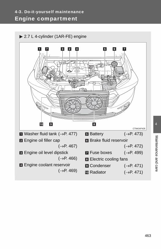
4
Maintenance and care
4-3. Do-it-yourself maintenance
Engine compartment
2.7 L 4-cylinder (1AR-FE) engine
Washer fluid tank (→P. 477)Engine oil filler cap
(→P. 467)Engine oil level dipstick
(→P. 466)Engine coolant reservoir
(→P. 469)
Battery (→P. 473)Brake fluid reservoir
(→P. 472)Fuse boxes (→P. 499)Electric cooling fansCondenser (→P. 471)Radiator (→P. 471)
463

4-3. Do-it-yourself maintenance
3.5 L V6 (2GR-FE) engine
Washer fluid tank (→P. 477)Engine oil filler cap
(→P. 467)Engine oil level dipstick
(→P. 466)Engine coolant reservoir
(→P. 469)
Battery (→P. 473)Brake fluid reservoir
(→P. 472)Fuse boxes (→P. 499)Electric cooling fansCondenser (→P. 471)Radiator (→P. 471)
464

4-3. Do-it-yourself maintenance
4
Maintenance and care
Engine compartment cover
■ Removing the engine compartment cover
■ Installing the clips
NOTICE
■After installing an engine compartment coverMake sure that the cover is securely installed in its original position.
465

4-3. Do-it-yourself maintenance
Engine oil
With the engine at operating temperature and turned off, check the oillevel on the dipstick.
■ Checking the engine oilPark the vehicle on level ground. After warming up the engineand turning it off, wait more than five minutes for the oil todrain back into the bottom of the engine.
Hold a rag under the end andpull the dipstick out.
Wipe the dipstick clean.Reinsert the dipstick fully.Holding a rag under the end, pull the dipstick out and checkthe oil level.Wipe the dipstick and reinsert it fully.
2.7 L 4-cylinder (1AR-FE) engine
LowFull
STEP 1
STEP 2
STEP 3
STEP 4
STEP 5
STEP 6
466

4-3. Do-it-yourself maintenance
4
Maintenance and care
3.5 L V6 (2GR-FE) engine
LowFull
■ Adding engine oilIf the oil level is below or nearthe low level mark, add engineoil of the same type as thatalready in the engine.
Make sure to check the oil type and prepare the items needed beforeadding oil.
Remove the oil filler cap.Add engine oil slowly, checking the dipstick.Install the filler cap, turning it clockwise.
Engine oil selection →P. 576
Oil quantity(Low → Full) 1.6 qt. (1.5 L, 1.3 Imp. qt.)
Items Clean funnel
STEP 1
STEP 2
STEP 3
467

4-3. Do-it-yourself maintenance
■Engine oil consumption●The amount of engine oil consumed depends on the oil viscosity, the
quality of the oil and the way the vehicle is driven.
●More oil is consumed under driving conditions such as high speeds andfrequent acceleration and deceleration.
●A new engine consumes more oil.
●When judging the amount of oil consumption, keep in mind that the oilmay have become diluted, making it difficult to judge the true level accu-rately.
●Oil consumption: Max. 1.1 qt./600 miles, 0.9 Imp. qt./600 miles (1.0 L per1000 km)
● If your vehicle consume more than 1.1 qt. (1.0 L, 0.9 Imp. qt.) every 600miles (1000 km), contact your Toyota dealer.
CAUTION
■Used engine oil●Used engine oil contains potentially harmful contaminants which may
cause skin disorders such as inflammation or skin cancer, so care shouldbe taken to avoid prolonged and repeated contact. To remove used engineoil from your skin, wash thoroughly with soap and water.
●Dispose of used oil and filters only in a safe and acceptable manner. Donot dispose of used oil and filters in household trash, in sewers or onto theground. Call your Toyota dealer, service station or auto parts store forinformation concerning recycling or disposal.
●Do not leave used engine oil within the reach of children.
468

4-3. Do-it-yourself maintenance
4
Maintenance and care
Engine coolant
The coolant level is satisfactory if it is between the “FULL” and “LOW”lines on the reservoir when the engine is cold.
Reservoir cap“FULL”“LOW”
If the level is on or below the“LOW” line, add coolant up to the“FULL” line.
NOTICE
■To prevent serious engine damageCheck the oil level on a regular basis.
■When replacing the engine oil●Be careful not to spill engine oil on the vehicle components.
●Avoid overfilling, as the engine could be damaged.
●Check the oil level on the dipstick every time you refill the vehicle.
●Be sure the engine oil filler cap is properly tightened.
469

4-3. Do-it-yourself maintenance
■ If the coolant level drops within a short time after replenishingVisually check the radiator, hoses, engine coolant filler cap, radiator cap,drain cock and water pump. If you cannot find a leak, have your Toyota dealer test the cap opening pres-sure and check for leaks in the cooling system.
■Coolant selectionOnly use “Toyota Super Long Life Coolant” or similar high quality ethyleneglycol based non-silicate, non-amine, non-nitrite, and non-borate coolantwith long-life hybrid organic acid technology.
U.S.A.: Toyota Super Long Life Coolant is a mixture of 50% coolant and50% deionized water. (Enabled: -31°F [-35°C])
Canada: Toyota Super Long Life Coolant is a mixture of 55% coolant and45% deionized water. (Enabled: -44°F [-42°C])
For more details about engine coolant, contact your Toyota dealer.
CAUTION
■When the engine is hotDo not remove the coolant reservoir cap. The cooling system may be under pressure and may spray hot coolant if thecap is removed, causing burns or other injuries.
NOTICE
■When adding engine coolantCoolant is neither plain water nor straight antifreeze. The correct mixture ofwater and antifreeze must be used to provide proper lubrication, corrosionprotection and cooling. Be sure to read the antifreeze or coolant label.
■ If you spill coolantBe sure to wash it off with water to prevent damage to parts or paint.
470

4-3. Do-it-yourself maintenance
4
Maintenance and care
Radiator and condenser
Check the radiator and condenser, and clear away any foreignobjects. If either of the above parts are extremely dirty or you are not sure oftheir condition, have your vehicle checked by your Toyota dealer.
CAUTION
■When the engine is hotDo not touch the radiator or condenser as they may be hot and may causeburns.
■When the electric cooling fans are operatingDo not touch the engine compartment.Vehicles without smart key system: The electric cooling fans may keep rotat-ing for about 3 minutes after the engine switch is turned to the “LOCK” posi-tion.With the engine switch in the “ON” position, the electric cooling fans mayautomatically start to run if the air conditioning is on and/or the coolant tem-perature is high. Be sure the engine switch is in the “LOCK” position whenworking near the electric cooling fan or radiator grille.Vehicles with smart key system: The electric cooling fan may keep rotatingfor about 3 minutes even after the “ENGINE START STOP” switch is OFF.With the “ENGINE START STOP” switch in IGNITION ON mode, the electriccooling fans may automatically start to run if the air conditioning is on and/orthe coolant temperature is high. Be sure the “ENGINE START STOP” switchis OFF when working near the electric cooling fans or radiator grille.
471

4-3. Do-it-yourself maintenance
Brake fluid
■ Checking fluid levelThe brake fluid level should bebetween the “MAX” and “MIN”lines on the tank.
Make sure to check the fluid type and prepare the necessary items.
■ Adding fluid
Fluid type SAE J1703 or FMVSS No.116 DOT 3
Items Clean funnel
■Brake fluid can absorb moisture from the airExcess moisture in the fluid can cause a dangerous loss of braking effi-ciency. Use only newly opened brake fluid.
CAUTION
■When filling the reservoirTake care because brake fluid can harm your hands or eyes and damagepainted surfaces.If fluid gets in your eyes, flush your eyes with clean water immediately.
If you still experience discomfort, see a doctor.
472

4-3. Do-it-yourself maintenance
4
Maintenance and care
Battery
■ Battery exteriorMake sure that the battery terminals are not corroded and thatthere are no loose connections, cracks, or loose clamps.
TerminalsHold-down clamp
■ Checking battery fluidCheck that the level is between“UPPER”/“MAX” and “LOWER”/“MIN”.
“UPPER”/“MAX”“LOWER”/“MIN”
If the fluid level is at or below“LOWER”/“MIN”, add distilledwater.
NOTICE
■ If the fluid level is low or highIt is normal for the brake fluid level to go down slightly as the brake padswear or when the fluid level in the accumulator is high.If the reservoir needs frequent refilling, it may indicate a serious problem.
473

4-3. Do-it-yourself maintenance
■ Adding distilled waterLowO.K.
Remove the vent plug.Add distilled water.If the “UPPER”/“MAX” line cannot be seen, check the fluid level bylooking directly at the cell.
Put the vent plug back on and close securely.
■Before rechargingWhen recharging, the battery produces hydrogen gas which is flammableand explosive. Therefore, before recharging:
● If recharging with the battery installed on the vehicle, be sure to discon-nect the ground cable.
●Make sure the power switch on the charger is off when connecting anddisconnecting the charger cables to the battery.
■After recharging the battery (vehicles with smart key system)The engine may not start. Follow the procedure below to initialize the sys-tem.
Shift the shift lever to P.
Open and close any of the doors.
Restart the engine.
STEP 1
STEP 2
STEP 3
STEP 1
STEP 2
STEP 3
474

4-3. Do-it-yourself maintenance
4
Maintenance and care
CAUTION
■Chemicals in the batteryA battery contains poisonous and corrosive sulfuric acid and may producehydrogen gas which is flammable and explosive. To reduce the risk of deathor serious injury, take the following precautions while working on or near thebattery:
●Do not cause sparks by touching the battery terminals with tools.
●Do not smoke or light a match near the battery.
●Avoid contact with eyes, skin and clothes.
●Never inhale or swallow electrolyte.
●Wear protective safety glasses when working near the battery.
●Keep children away from the battery.
■Where to safely charge the batteryAlways charge the battery in an open area. Do not charge the battery in agarage or closed room where there is not sufficient ventilation.
■How to recharge the batteryOnly perform a slow charge (5 A or less). The battery may explode ifcharged at a quicker rate.
■Emergency measures regarding electrolyte● If electrolyte gets in your eyes
Flush your eyes with clean water for at least 15 minutes and get immedi-ate medical attention. If possible, continue to apply water with a sponge orcloth while traveling to the nearest medical facility.
● If electrolyte gets on your skinWash the affected area thoroughly. If you feel pain or burning, get medicalattention immediately.
475

4-3. Do-it-yourself maintenance
CAUTION
● If electrolyte gets on your clothesIt can soak through clothing on to your skin. Immediately take off the cloth-ing and follow the procedure above if necessary.
● If you accidentally swallow electrolyteDrink a large quantity of water or milk. Follow with milk of magnesia,beaten raw egg or vegetable oil. Get emergency medical attention immedi-ately.
NOTICE
■When recharging the batteryNever recharge the battery while the engine is running. Also, be sure allaccessories are turned off.
■When adding distilled waterAvoid overfilling. Water spilled during battery recharging may cause corro-sion.
476

4-3. Do-it-yourself maintenance
4
Maintenance and care
Washer fluid
Add washer fluid in the followingsituations.
● Any washer does not work.
● The low washer fluid warninglight comes on (vehicles with-out multi-information display).
● The warning messageappears on the multi-informa-tion display (vehicles withmulti-information display).
CAUTION
■When adding washer fluidDo not add the washer fluid when the engine is hot or running, as the washerfluid contains alcohol and may catch fire if spilled on the engine etc.
NOTICE
■Do not use any fluid other than washer fluidDo not use soapy water or engine antifreeze instead of washer fluid. Doing so may cause streaking on the vehicle’s painted surfaces.
■Diluting washer fluidDilute washer fluid with water as necessary. Refer to the freezing temperatures listed on the label of the washer fluid bot-tle.
477
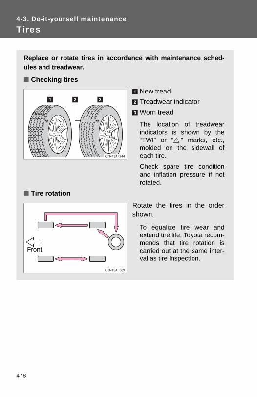
4-3. Do-it-yourself maintenance
Tires
Replace or rotate tires in accordance with maintenance sched-ules and treadwear.
■ Checking tiresNew treadTreadwear indicatorWorn tread
The location of treadwearindicators is shown by the“TWI” or “ ” marks, etc.,molded on the sidewall ofeach tire.
Check spare tire conditionand inflation pressure if notrotated.
■ Tire rotationRotate the tires in the ordershown.
To equalize tire wear andextend tire life, Toyota recom-mends that tire rotation iscarried out at the same inter-val as tire inspection.
Front
478

4-3. Do-it-yourself maintenance
4
Maintenance and care
■ The tire pressure warning systemYour Toyota is equipped with a tire pressure warning system thatuses tire pressure warning valves and transmitters to detect lowtire inflation pressure before serious problems arise. (→P. 531, 539)
479

4-3. Do-it-yourself maintenance
Installing tire pressure warning valves and transmitters
When replacing tires or wheels, tire pressure warning valves andtransmitters must also be installed.
When new tire pressure warning valves and transmitters areinstalled, new tire pressure warning valve and transmitter ID codesmust be registered in the tire pressure warning computer and the tirepressure warning system must be initialized. Have tire pressurewarning valve and transmitter ID codes registered by your Toyotadealer. (→P. 481)
Initializing the tire pressure warning system
■ The tire pressure warning system must be initialized when thetire inflation pressure is changed (such as when changingtraveling speed or towing a trailer.)
When the tire pressure warning system is initialized, the current tireinflation pressure is set as the benchmark pressure.
■ How to initialize the tire pressure warning systemPark the vehicle in a safe place and turn the “ENGINE STARTSTOP” switch or the engine switch OFF.While the vehicle is moving, initialization is not performed.
Adjust the tire inflation pressure to the specified cold tire infla-tion pressure level. (→P. 584)Make sure to adjust the tire pressure to the specified cold tireinflation pressure level. The tire pressure warning system willoperate based on this pressure level.
Turn the “ENGINE START STOP” switch to IGNITION ONmode (vehicles with smart key system) or the engine switch tothe “ON” position (vehicles without smart key system).
STEP 1
STEP 2
STEP 3
480

4-3. Do-it-yourself maintenance
4
Maintenance and care
Push and hold the tire pressurewarning reset switch until the tirepressure warning light blinksslowly 3 times.
Vehicles without smart key systemWait for a few minutes with the engine switch in the “ON” posi-tion, and then turn the engine switch to the “LOCK” position.
Vehicles with smart key systemWait for a few minutes with IGNITION ON mode, and thenturn the “ENGINE START STOP” switch OFF.
Registering ID codes
The tire pressure warning valve and transmitter is equipped with aunique ID code. When replacing a tire pressure warning valve andtransmitter, it is necessary to register the ID code of the tire pressurewarning valve and transmitter. Have the ID code registered by yourToyota dealer.
STEP 4
STEP 5
STEP 5
481

4-3. Do-it-yourself maintenance
■When to replace your vehicle's tiresTires should be replaced if:●You have tire damage such as cuts, splits, cracks deep enough to
expose the fabric, or bulges indicating internal damage●A tire goes flat repeatedly or cannot be properly repaired due to the
size or location of a cut or other damageIf you are not sure, consult with your Toyota dealer.
■Replacing tires and wheelsIf the ID code of the tire pressure warning valve and transmitter is notregistered, the tire pressure warning system will not work properly. Afterdriving for about 20 minutes, the tire pressure warning light comes onafter blinking for 1 minute to indicate a system malfunction.
■Tire lifeAny tire over 6 years old must be checked by a qualified technician evenif they have seldom or never been used or damage is not obvious.
■ If the tread wears down below 0.16 in. (4 mm) on snow tiresThe effectiveness of snow tires is lost.
■When the tire pressure warning valves and transmitter are removedfrom the wheel on occasions such as when replacing tiresThe tire inflation pressure data updated before servicing is retained.
■Maximum load of tireCheck that the number given by dividing the maximum load by 1.10 ofthe replacement tire is greater than 1/2 of the Gross Axle Weight Ratings(GAWR) of either the front axle or the rear axle, whichever is greater.
For the GAWR, see the CertificationLabel. For the maximum load of thetire, see the load limit at maximum coldtire inflation pressure mentioned on thesidewall of the tire. (→P. 590)
482

4-3. Do-it-yourself maintenance
4
Maintenance and care
■Tire types1 Summer tires
Summer tires are high-speed performance tires best suited to highwaydriving under dry conditions. Since summer tires do not have the sametraction performance as snow tires, summer tires are inadequate fordriving on snow-covered or icy roads. For driving on snow-coveredroads or icy roads, the use of snow tires is recommended. Wheninstalling snow tires, be sure to replace all four tires.
2 All season tiresAll season tires are designed to provide better traction in snow and tobe adequate for driving in most winter conditions, as well as for useyear round. All season tires, however, do not have adequate tractionperformance compared with snow tires in heavy or loose snow. Also,all season tires fall short in acceleration and handling performancecompared with summer tires in highway driving.
3 Snow tiresFor driving on snow-covered roads or icy roads, we recommend usingsnow tires. If you need snow tires, select tires of the same size, con-struction and load capacity as the originally installed tires. Since yourvehicle has radial tires as original equipment, make sure your snowtires also have radial construction. Do not install studded tires withoutfirst checking local regulations for possible restriction. Snow tiresshould be installed on all wheels. (→P. 243)
■ Initializing the tire pressure warning systemInitialize the tire pressure warning system with the tire inflation pressureadjusted to the specified level.
■ If you push the tire pressure warning reset switch accidentallyIf initialization is performed, adjust the tire inflation pressure to the speci-fied level and initialize the tire pressure warning system again.
483

4-3. Do-it-yourself maintenance
■When the initialization of the tire pressure warning system hasfailedInitialization can be completed in a few minutes. However, in the follow-ing cases, the settings have not been recorded and the system will notoperate properly. If repeated attempts to record tire inflation pressuresettings are unsuccessful, have the vehicle inspected by your Toyotadealer.●When operating the tire pressure warning reset switch, the tire pres-
sure warning light does not blink 3 times. ●After carrying out the initialization procedure, the tire pressure warn-
ing light blinks for 1 minute then stays on after driving for about 20minutes.
■Routine tire inflation pressure checksThe tire pressure warning system does not replace routine tire inflationpressure checks. Make sure to check tire inflation pressure as part ofyour routine of daily vehicle checks.
■Tire pressure warning system certificationFor vehicles sold in the U.S.A.
FCC ID: PAXPMV107JFCC ID: HYQ13BCXThis device complies with Part 15 of the FCC Rules. Operation is subjectto the following two conditions: (1) this device may not cause harmfulinterference, and (2) this device must accept any interference received,including interference that may cause undesired operation.FCC WARNING: Changes or modifications not expressly approved by the party responsi-ble for compliance could void the user's authority to operate the equip-ment.
For vehicles sold in CanadaOperation is subject to the following two conditions: (1) this device maynot cause interference, and (2) this device must accept any interference,including interference that may cause undesired operation of the device.
484

4-3. Do-it-yourself maintenance
4
Maintenance and care
CAUTION
■When inspecting or replacing tiresObserve the following precautions to prevent accidents. Failure to do somay cause damage to parts of the drive train, as well as dangerous han-dling characteristics, which may lead to an accident resulting in death orserious injury.●Do not mix tires of different makes, models or tread patterns.
Also, do not mix tires of remarkably different treadwear.●Do not use tire sizes other than those recommended by Toyota.●Do not mix differently constructed tires (radial, bias-belted or bias-ply
tires).●Do not mix summer, all season and winter tires.●Do not tow the vehicle with the spare tire installed.
■When initializing the tire pressure warning systemDo not push the tire pressure warning reset switch without first adjustingthe tire inflation pressure to the specified level. Otherwise, the tire pres-sure warning light may not come on even if the tire inflation pressure islow, or it may come on when the tire inflation pressure is actually normal.
485

4-3. Do-it-yourself maintenance
NOTICE
■Repairing or replacing tires, wheels, tire pressure warning valves,transmitters and tire valve caps●When removing or fitting the wheels, tires or the tire pressure warning
valve and transmitter, contact your Toyota dealer as the tire pressurewarning valve and transmitter may be damaged if not handled correctly.
●When replacing tire valve caps, do not use tire valve caps other than thosespecified. The cap may become stuck.
■To avoid damage to the tire pressure warning valves and transmit-tersWhen a tire is repaired with liquid sealants, the tire pressure warningvalve and transmitter may not operate properly. If a liquid sealant isused, contact your Toyota dealer or other qualified service shop as soonas possible. Make sure to replace the tire pressure warning valve andtransmitter when replacing the tire. (→P. 480)
■Do not use puncture sealant sprays to repair flatsPuncture sealant sprays may damage tire pressure warning valves andtransmitters.
■Driving on rough roadsTake particular care when driving on roads with loose surfaces or pot-holes.These conditions may cause losses in tire inflation pressure, reducingthe cushioning ability of the tires. In addition, driving on rough roads maycause damage to the tires themselves, as well as the vehicle's wheelsand body.
■ If tire inflation pressures become low while drivingDo not continue driving, or your tires and/or wheels may be ruined.
486

4
Maintenance and care
4-3. Do-it-yourself maintenance
Tire inflation pressure
■ Tire inflation pressureThe recommended cold tire inflation pressure and tire size is dis-played on the tire and loading information label. (→P. 590)
■ Inspection and adjustment procedureTire valveTire pressure gauge
Remove the tire valve cap.STEP 1
487

4-3. Do-it-yourself maintenance
■Tire inflation pressure check intervalYou should check tire inflation pressure every two weeks, or at leastonce a month.Do not forget to check the spare.
■Effects of incorrect tire inflation pressureDriving with incorrect tire inflation pressure may result in the following:●Reduced fuel efficiency●Reduced driving comfort and tire life●Reduced safety●Damage to the drive trainIf a tire needs frequent reinflating, have it checked by your Toyota dealer.
■ Instructions for checking tire inflation pressureWhen checking tire inflation pressure, observe the following:●Check only when the tires are cold.
If your vehicle has been parked for at least 3 hours and has not beendriven for more than 1 mile or 1.5 km, you will get an accurate coldtire inflation pressure reading.
Press the tip of the tire pressure gauge onto the tire valve.Read the pressure using the graduations of the gauge.If the tire inflation pressure is not within the recommendedlevels, adjust the pressure.If you add too much air, press the center of the valve tolower.After completing the tire inflation pressure measurementand adjustment, apply soapy water to the valve and checkfor leakage.Reinstall the tire valve cap.
STEP 2
STEP 3
STEP 4
STEP 5
STEP 6
488

4-3. Do-it-yourself maintenance
4
Maintenance and care
●Always use a tire pressure gauge.The appearance of the tire can be misleading. In addition, tire infla-tion pressures that are even just a few pounds off can degrade rideand handling.
●Do not bleed or reduce tire inflation pressure after driving. It is normalfor the tire inflation pressure to be higher after driving.
●Never exceed the vehicle capacity weight.Passengers and luggage weight should be placed so that the vehicleis balanced.
CAUTION
■Proper inflation is critical to save tire performanceKeep your tires properly inflated. Otherwise, the following conditions may occur and result in an accidentcausing death or serious injury.●Excessive wear●Uneven wear●Poor handling●Possibility of blowouts resulting from overheated tires●Poor sealing of the tire bead●Wheel deformation and/or tire separation●A greater possibility of tire damage from road hazards
NOTICE
■When inspecting and adjusting tire inflation pressureBe sure to reinstall the tire valve caps.Without the valve caps, dirt or moisture could get into the valve andcause air leakage, which could result in an accident. If the caps havebeen lost, replace them as soon as possible.
489

4-3. Do-it-yourself maintenance
Wheels
If a wheel is bent, cracked or heavily corroded, it should bereplaced.Otherwise, the tire may separate from the wheel or cause loss ofhandling control.
■ Wheel selectionWhen replacing wheels, care should be taken to ensure thatthey are equivalent to those removed in load capacity, diameter,rim width, and inset*.Replacement wheels are available at your Toyota dealer.
*: Conventionally referred to as “offset”.
Toyota does not recommend using:
● Wheels of different sizes or types
● Used wheels
● Bent wheels that have been straightened
■ Aluminum wheel precautions● Use only Toyota wheel nuts and wrenches designed for use
with your aluminum wheels.
● When rotating, repairing or changing your tires, check that thewheel nuts are still tight after driving 1000 miles (1600 km).
● Be careful not to damage the aluminum wheels when usingtire chains.
● Use only Toyota genuine balance weights or equivalent and aplastic or rubber hammer when balancing your wheels.
490

4-3. Do-it-yourself maintenance
4
Maintenance and care
■When replacing wheelsThe wheels of your Toyota are equipped with tire pressure warningvalves and transmitters that allow the tire pressure warning system toprovide advanced warning in the event of a loss in tire inflation pressure.Whenever wheels are replaced, the tire pressure warning valves andtransmitters must be installed. (→P. 480)
CAUTION
■When replacing wheels●Do not use wheels that are a different size from those recommended in
the Owner’s Manual, as this may result in loss of handling control.●Never use an inner tube in a leaking wheel which is designed for a
tubeless tire. Doing so may result in an accident, causing seriousinjury or death.
■When installing the wheel nuts
●Never use oil or grease on the wheel bolts or wheel nuts.Oil and grease may cause the wheel nuts to be excessively tightened,leading to bolt or disc wheel damage. In addition, the oil or grease cancause the wheel nuts to loosen and the wheel may fall off, causing an acci-dent and resulting in death or serious injury. Remove any oil or greasefrom the wheel bolts or wheel nuts.
●Be sure to install the wheel nuts withthe tapered end facing inward. Install-ing the nuts with the tapered end facingoutward can cause wheel to break andeventually cause a wheel to come offwhile driving, which could lead to anaccident resulting in death or seriousinjury.
Taperedportion
491

4-3. Do-it-yourself maintenance
NOTICE
■Replacing tire pressure warning valves and transmitters●Because tire repair or replacement may affect the tire pressure
warning valves and transmitters, make sure to have tires serviced byyour Toyota dealer or other qualified service shop. In addition, makesure to purchase your tire pressure warning valves and transmitters atyour Toyota dealer.
●Ensure that only genuine Toyota wheels are used on your vehicle.Tire pressure warning valves and transmitters may not work properlywith non-genuine wheels.
492

4
Maintenance and care
4-3. Do-it-yourself maintenance
Air conditioning filter
The air conditioning filter must be changed regularly to maintain airconditioning efficiency.
■ Removal methodVehicles without smart key system: Turn the engine switchOFF.Vehicles with smart key system: Turn the “ENGINE STARTSTOP” switch OFF.
Open the glove box. Slide offthe damper.
Push each side of the glovebox to release the pins. Thenpull the glove box downtoward you.
Lift up the cover.
STEP 1
STEP 2
STEP 3
STEP 4
493

4-3. Do-it-yourself maintenance
■Checking intervalInspect and replace the air conditioning filter according to the maintenanceschedule. In dusty areas or areas with heavy traffic flow, replacement maybe required. (For scheduled maintenance information, please refer to the“Scheduled Maintenance Guide” or “Owner’s Manual Supplement”.)
■ If air flow from the vents decreases dramaticallyThe filter may be clogged. Check the filter and replace if necessary.
Remove the filter cover.
■ Replacement methodRemove the air conditioningfilter and replace it with a newone.
The “↑UP” marks shown on thefilter should be pointing up.
STEP 5
494

4-3. Do-it-yourself maintenance
4
Maintenance and care
NOTICE
■When using the air conditioning systemMake sure that a filter is always installed.
Using the air conditioning system without a filter may cause damage to thesystem.
495

4-3. Do-it-yourself maintenance
Wireless remote control/electronic key battery
Replace the battery with a new one if it is discharged.
■ You will need the following items:● Flathead screwdriver (To prevent damage to the key, cover
the tip of the screwdriver with a rag.)
● Small Phillips-head screwdriver
● Lithium battery CR2032 (vehicles without smart key system),CR1632 (vehicles with smart key system)
■ Replacing the battery (vehicles without smart key system)Remove the cover using acoin protected with tape etc.
Remove the discharged trans-mitter battery.
Insert a new battery with the“+” terminal facing up.
STEP 1
STEP 2
496

4-3. Do-it-yourself maintenance
4
Maintenance and care
■ Replacing the battery (vehicles with smart key system)Take out the mechanical key.
Remove the cover.
Remove the depleted battery.
Insert a new battery with the“+” terminal facing up.
STEP 1
STEP 2
STEP 3
497

4-3. Do-it-yourself maintenance
■ If the electronic key battery is dischargedThe following symptoms may occur.
●The smart key system and wireless remote control will not function prop-erly.
●The operational range is reduced.
■Use a CR2032 (vehicles without smart key system) or CR1632 (vehicleswith smart key system) lithium battery●Batteries can be purchased at your Toyota dealer, jewelers, or camera
stores.
●Replace only with the same or equivalent type recommended by yourToyota dealer.
●Dispose of used batteries according to the local laws.
CAUTION
■Removed battery and other partsKeep away from children. These parts are small and if swallowed by a child,they can cause choking. Failure to do so could result in death or seriousinjury.
NOTICE
■For normal operation after replacing the batteryObserve the following precautions to prevent accidents.
●Always work with dry hands.Moisture may cause the battery to rust.
●Do not touch or move any other components inside the remote control.
●Do not bend either of the battery terminals.
498

4
Maintenance and care
4-3. Do-it-yourself maintenance
Checking and replacing fuses
If any of the electrical components do not operate, a fuse may haveblown. If this happens, check and replace the fuses as necessary.
Vehicles without smart key system: Turn the engine switchOFF.Vehicles with smart key system: Turn the “ENGINE STARTSTOP” switch OFF.Open the fuse box cover.
Engine compartment (type A)Push the tab in and lift thefuse box cover off.
Engine compartment (type B)Push the tab in and lift thefuse box cover off. (ifequipped)
STEP 1
STEP 2
499
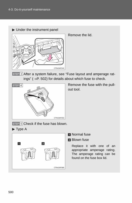
4-3. Do-it-yourself maintenance
Under the instrument panelRemove the lid.
After a system failure, see “Fuse layout and amperage rat-ings” (→P. 502) for details about which fuse to check.
Remove the fuse with the pull-out tool.
Check if the fuse has blown.Type A
Normal fuseBlown fuse
Replace it with one of anappropriate amperage rating.The amperage rating can befound on the fuse box lid.
STEP 3
STEP 4
STEP 5
500

4-3. Do-it-yourself maintenance
4
Maintenance and care
Type BNormal fuseBlown fuse
Replace it with one of anappropriate amperage rating.The amperage rating can befound on the fuse box lid.
Type CNormal fuseBlown fuse
Contact your Toyota dealer.
Type DNormal fuseBlown fuse
Contact your Toyota dealer.
501

4-3. Do-it-yourself maintenance
Fuse layout and amperage ratings
■ Engine compartmentType A (fuse block on the back of the cover)
Type A (fuse block)
Fuse Ampere Circuit
1 SPARE 7.5 A Spare fuse
2 SPARE 15 A Spare fuse
3 SPARE 25 A Spare fuse
502

4-3. Do-it-yourself maintenance
4
Maintenance and care
4 DEF RLY 10 A Rear window defogger
5 MIR HTR 10 A Outside rear view mirror defoggers
6 PWR OUTLET 20 A Power outlet
7 DOOR NO.1 25 A Multiplex communication system
8 EFI NO.2 10 AMultiport fuel injection system/sequential multiport fuel injection system
9 EFI NO.3 10 AMultiport fuel injection system/sequential multiport fuel injection system
10 INJ NO.1 15 A Starting system
11 INJ NO.2 10 AMultiport fuel injection system/sequential multiport fuel injection system
12 HTR 50 A Air conditioning system
13 VSC NO.1 50 A Enhanced vehicle stability control system
14 FAN MAIN 50 A Electric cooling fans
15 VSC NO.2 30 A Enhanced vehicle stability control system
16 PTC NO.1 50 A Air conditioning system
17 PTC NO.2 30 A Air conditioning system
18 PTC NO.3 30 A Air conditioning system
19 RR CLR 40 A Air conditioning system
20 RR DEF 30 A Rear window defogger
21 PBD 30 A Power back door
22 ALT 140 A
MIR HTR, PWR OUTLET, DOOR NO.1, HTR, RR DEF, FAN MAIN, VSC NO.1, PTC NO.1, RR CLR, PTC NO.2, PTC NO.3, VSC NO.2, PBD
Fuse Ampere Circuit
503

4-3. Do-it-yourself maintenance
23 EPS 80 A Electric power steering
24 ST 30 A Starting system
25 CRT 10 A Rear seat entertainment system, audio system
26 RADIO NO.1 20 A Audio system
27 ECU-B NO.1 10 A
Steering sensor, gauges and meters, clock, main body ECU, wireless remote control, smart key system, power back door, multi-information display, front passen-ger occupant classification system
28 DOME 10 A
Vanity lights, personal lights, inte-rior light, gauges and meters, engine switch light, door courtesy lights
29 TOWING 30 A Trailer lights
30 STR LOCK 20 A Steering lock system
31 EFI MAIN 25 AMultiport fuel injection system/sequential multiport fuel injection system, EFI NO.2, EFI NO.3
32 HAZ 15 A Turn signal lights
33 IG2 25 A INJ NO.1, INJ NO.2, IGN, GAUGE NO.2
34 AMP 15 A Audio system
35 RR FOG 7.5 A No circuit
36 DEICER 15 A Windshield wiper de-icer
37 G/H 10 A Glass hatch, multiplex communica-tion system, outer foot lights
38 ALT-S 7.5 A Charging system
39 AM2 7.5 A Multiplex communication system
40 H-LP LH HI 15 A Left-hand headlight (high beam)
Fuse Ampere Circuit
504

4-3. Do-it-yourself maintenance
4
Maintenance and care
Type B (if equipped)
41 H-LP RH HI 15 A Right-hand headlight (high beam)
42 H-LP LH LO 15 A Left-hand headlight (low beam)
43 H-LP RH LO 15 A Right-hand headlight (low beam)
44 HORN 10 A Horn
45 EFI NO.1 10 AMultiport fuel injection system/sequential multiport fuel injection system, smart key system
46 ETCS 10 AMultiport fuel injection system/sequential multiport fuel injection system
47 A/F 20 A Air fuel ratio sensor
48 S-HORN 7.5 A S-HORN
Fuse Ampere Circuit
1 INV-W/P 15 A No circuit
2 IGCT NO.2 7.5 A No circuit
3 A/C 10 A No circuit
Fuse Ampere Circuit
505
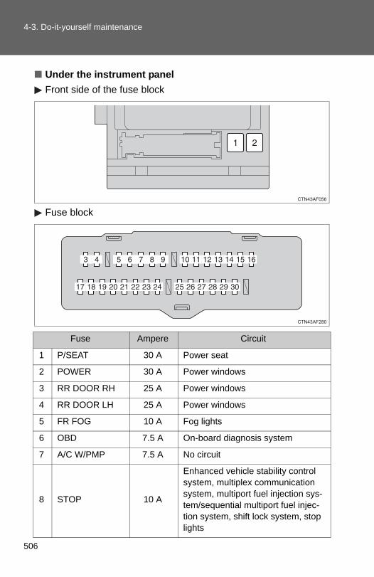
4-3. Do-it-yourself maintenance
■ Under the instrument panelFront side of the fuse block
Fuse block
Fuse Ampere Circuit
1 P/SEAT 30 A Power seat
2 POWER 30 A Power windows
3 RR DOOR RH 25 A Power windows
4 RR DOOR LH 25 A Power windows
5 FR FOG 10 A Fog lights
6 OBD 7.5 A On-board diagnosis system
7 A/C W/PMP 7.5 A No circuit
8 STOP 10 A
Enhanced vehicle stability control system, multiplex communication system, multiport fuel injection sys-tem/sequential multiport fuel injec-tion system, shift lock system, stop lights
506

4-3. Do-it-yourself maintenance
4
Maintenance and care
9 DOOR NO.2 25 A Power windows
10 AM1 7.5 A Starting system
11 P/SEAT (PS) 30 A Power seat
12 A/C NO.1 10 A Air conditioning system
13 FUEL OPN 7.5 A No circuit
14 S/ROOF 20 A Electric moon roof
15 TAIL 15 A Parking lights, tail lights, license plate lights, fog lights, trailer lights
16 PANEL 7.5 A Glove box light, instrument panel lights, switch illumination
17 ECU IG NO.1 10 A
Multiplex communication system, electric moon roof, electronically controlled automatic transmission system, power back door, seat heaters, tire pressure warning sys-tem, electric power steering, anti-glare inside rear view mirror, shift lock system, tire pressure warning system
18 ECU IG NO.2 7.5 A Enhanced vehicle stability control system
19 A/C NO.2 10 A Air conditioning system
20 WASH 20 A Windshield and rear window washer
21 S-HTR 20 A Seat heaters
Fuse Ampere Circuit
507

4-3. Do-it-yourself maintenance
22 GAUGE NO.1 10 A
Audio system, back-up lights, charging system, emergency flash-ers, traction control system, wind-shield wiper de-icer, air conditioning system, charging sys-tem, rear view monitor system, trailer lights, multiport fuel injection system/sequential multiport fuel injection system
23 FR WIP 30 A Windshield wipers and washer
24 RR WIP 15 A Rear window wiper and washer
25 IGN 10 A
Multiport fuel injection system/sequential multiport fuel injection system, steering lock system, smart key system, SRS airbag sys-tem
26 GAUGE NO.2 7.5 A Gauges and meters, rear view monitor system
27 ECU-ACC 7.5 AOutside rear view mirrors, shift lock system, smart key system, multi-plex communication system
28 ACC SOCK NO.1 15 A Power outlet
29 ACC SOCK NO.2 15 A Power outlet
30 RADIO NO.2 7.5 AAudio system, clock, rear seat entertainment system, interior lights, personal lights
Fuse Ampere Circuit
508

4-3. Do-it-yourself maintenance
4
Maintenance and care
■After a fuse is replaced● If the lights do not turn on even after the fuse has been replaced, a bulb
may need replacement. (→P. 510)
● If the replaced fuse blows again, have the vehicle inspected by yourToyota dealer.
■ If there is an overload in the circuitsThe fuses are designed to blow, protecting the wiring harness from damage.
CAUTION
■To prevent system breakdowns and vehicle fireObserve the following precautions.Failing to do so may cause damage, and possibly a fire or injury.
●Never use a fuse of a higher amperage rating than indicated, or use anyother object in place of a fuse.
●Always use a genuine Toyota fuse or equivalent.Never replace a fuse with a wire, even as a temporary fix.This can cause extensive damage or even fire.
●Do not modify fuses or the fuse box.
NOTICE
■Before replacing fusesHave the cause of electrical overload determined and repaired by yourToyota dealer as soon as possible.
509

4-3. Do-it-yourself maintenance
Light bulbs
You may replace the following bulbs yourself. The difficulty level ofreplacement varies depending on the bulb. If necessary bulbreplacement seems difficult to perform, contact your Toyota dealer.
For more information about replacing other light bulbs, contact yourToyota dealer.
■ Prepare a replacement light bulb.Check the wattage of the light bulb being replaced. (→P. 586)
■ Turn the power back door main switch OFF. (vehicles withpower back door) →P. 62
■ Front bulb locations
Headlight high beams and daytime running lights (if equipped)
Headlight low beams
Fog lights (if equipped)
Parking, front sidemarker and front turnsignal lights
510

4-3. Do-it-yourself maintenance
4
Maintenance and care
Replacing light bulbs
■ HeadlightsTurn the bulb base counterclock-wise.
Low beam (outside)
High beam (inside)
■ Rear bulb locations
Back-up lights
Rear turn signal lights
Stop/tail and rearside marker lights
License plate lights
STEP 1
511

4-3. Do-it-yourself maintenance
Unplug the connector whiledepressing the lock release.
Low beam
High beam
■ Fog lights (if equipped)
Unplug the connector whiledepressing the lock release.
STEP 2
STEP 1
512

4-3. Do-it-yourself maintenance
4
Maintenance and care
Turn the bulb counterclockwise.
■ Parking, front side marker and front turn signal lightsTurn the bulb base counterclock-wise.
Remove the light bulb.
STEP 2
STEP 1
STEP 2
513

4-3. Do-it-yourself maintenance
■ Back-up lights, stop/tail and rear side marker, and rear turnsignal lightsLeft side
Open the back door and removethe cover.
To protect the cover, place a ragbetween the flathead screwdriverand cover as shown in the illus-trations.
Right side
Open the back door and removethe cover.
To protect the cover, place a ragbetween the flathead screwdriverand cover as shown in the illus-trations.
Turn the bulb base counterclock-wise.
Rear turn signal lightStop/tail and rear side markerlightBack-up light
STEP 1
STEP 1
STEP 2
514

4-3. Do-it-yourself maintenance
4
Maintenance and care
Remove the light bulb.
Rear turn signal lightStop/tail and rear side markerlightBack-up light
■ License plate lightsRemove the screw and removethe unit.
Turn the bulb base counterclock-wise.
Remove the light bulb.
STEP 3
STEP 1
STEP 2
STEP 3
515

4-3. Do-it-yourself maintenance
■ High mounted stoplight and outer foot lightsIf the high mounted stoplight or outer foot light has burnt out, haveit replaced by your Toyota dealer.
■Condensation build-up on the inside of the lensContact your Toyota dealer for more information in the following situations.Temporary condensation build-up on the inside of the headlight lens doesnot indicate a malfunction.
●Large drops of water are built up on the inside of the lens.
●Water has built up inside the headlight.
■LED high mounted stoplightThe high mounted stoplight consists of a number of LEDs. If any of the LEDsburn out, take your vehicle to your Toyota dealer to have the light replaced.
CAUTION
■Replacing light bulbs●Turn off the headlights. Do not attempt to replace the bulb immediately
after turning off the headlights.The bulbs become very hot and may cause burns.
●Do not touch the glass portion of the light bulb with bare hands. Hold thebulb by the plastic or metal portion.If the bulb is scratched or dropped it may blow out or crack.
●Fully install light bulbs and any parts used to secure them. Failing to do somay result in heat damage, fire, or water entering the headlight unit. Thismay damage the headlights or cause condensation to build up on the lens.
■To prevent damage or fireMake sure bulbs are fully seated and locked.
516

5-1. Essential information
Emergency flashers
NOTICE
■To prevent battery dischargeDo not leave the emergency flashers on longer than necessary when theengine is not running.
Use the emergency flashers if the vehicle malfunctions or isinvolved in an accident.
Vehicles without navigation system
Press the switch to flash allthe turn signal lights. To turnthem off, press the switchonce again.
Vehicles with navigation system
Press the switch to flash allthe turn signal lights. To turnthem off, press the switchonce again.
518

5
When trouble arises
5-1. Essential information
If your vehicle needs to be towed
Before towing
The following may indicate a problem with your transmission. Contactyour Toyota dealer before towing.
● The engine is running, but the vehicle will not move.
● The vehicle makes an abnormal sound.
If towing is necessary, we recommend having your vehicle towed byyour Toyota dealer or a commercial towing service, using a lift-typetruck or a flat bed truck.Use a safety chain system for all towing, and abide by all state/pro-vincial and local laws.2WD models: If towing from the front, the vehicle's rear wheels andaxles must be in good condition. (→P. 523)If they are damaged, use a towing dolly or flat bed truck.
519

5-1. Essential information
Emergency towing
If a tow truck is not available, in an emergency your vehicle may betemporarily towed using a cable or chain secured to the emergencytowing eyelet(s). This should only be attempted on hard surfacedroads for short distances at low speeds.A driver must be in the vehicle to steer and operate the brakes. Thevehicle’s wheels, drive train, axles, steering and brakes must be ingood condition.
Towing eyelets
■Emergency towing procedureRelease the parking brake.
Shift the shift lever to N.
Vehicles without smart key system: Turn the engine switch to “ACC” (engine off) or “ON” (engine run-ning) position.
Vehicles with smart key system: Turn the “ENGINE START STOP” switch to ACCESSORY (engineoff) or IGNITION ON (engine running) mode.
STEP 1
STEP 2
STEP 3
520

5
When trouble arises
5-1. Essential information
Installing a towing eyelet
Remove the eyelet cover using aflathead screwdriver.
To protect the bodywork, place arag between the screwdriver andthe vehicle body, as shown in theillustration.
Insert the towing eyelet into thehole and tighten partially byhand.
CAUTION
■Caution while towing●Use extreme caution when towing the vehicle.
Avoid sudden starts or erratic driving maneuvers which place excessivestress on the emergency towing eyelets and the cables or chains. Alwaysbe cautious of the surroundings and other vehicles while towing.
● If the engine is not running, the power assist for the brakes and steeringwill not function, making steering and braking more difficult.
NOTICE
■To prevent causing serious damage to the transmission Never tow this vehicle from the rear with the front wheels on the ground. This may cause serious damage to the transmission.
STEP 1
STEP 2
521

5-1. Essential information
Tighten down the towing eyeletsecurely using a wheel nutwrench.
STEP 3
■Location of the emergency towing eyelet→P. 540
CAUTION
■ Installing towing eyelet to the vehicleMake sure that towing eyelet is installed securely.If not securely installed, towing eyelet may come loose during towing. Thismay lead to accidents that cause serious injury or even death.
522
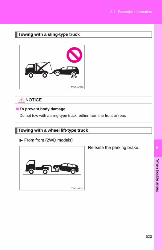
5
When trouble arises
5-1. Essential information
Towing with a sling-type truck
Towing with a wheel lift-type truck
From front (2WD models)
Release the parking brake.
NOTICE
■To prevent body damageDo not tow with a sling-type truck, either from the front or rear.
523

5-1. Essential information
From front (4WD models)
Use a towing dolly under the rearwheels.
From rear
Use a towing dolly under thefront wheels.
NOTICE
■To prevent damaging the vehicleWhen raising the vehicle, ensure adequate ground clearance for towing atthe opposite end of the raised vehicle. Without adequate clearance, thevehicle could be damaged while being towed.
■To prevent causing serious damage to the transmission (4WD models)Never tow this vehicle from the front with the rear wheels on the ground.
NOTICE
■To prevent causing serious damage to the transmissionNever tow this vehicle from the rear with the front wheels on the ground.
524
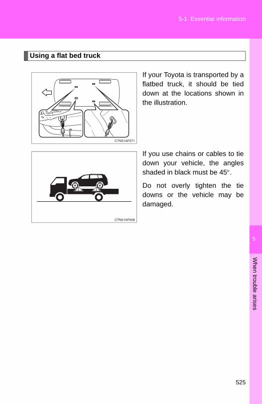
5
When trouble arises
5-1. Essential information
Using a flat bed truck
If your Toyota is transported by aflatbed truck, it should be tieddown at the locations shown inthe illustration.
If you use chains or cables to tiedown your vehicle, the anglesshaded in black must be 45°.
Do not overly tighten the tiedowns or the vehicle may bedamaged.
525

5-1. Essential information
If you think something is wrong
If you notice any of the following symptoms, your vehicle probablyneeds adjustment or repair. Contact your Toyota dealer as soon aspossible.
■ Visible symptoms● Fluid leaks under the vehicle
(Water dripping from the air conditioning after use is normal.)
● Flat-looking tires or uneven tire wear
● Engine coolant temperature gauge needle continually pointshigher than normal
■ Audible symptoms● Changes in exhaust sound
● Excessive tire squeal when cornering
● Strange noises related to the suspension system
● Pinging or other noises related to the engine
■ Operational symptoms● Engine missing, stumbling or running rough
● Appreciable loss of power
● Vehicle pulls heavily to one side when braking
● Vehicle pulls heavily to one side when driving on a level road
● Loss of brake effectiveness, spongy feeling, pedal almosttouches the floor
526

5
When trouble arises
5-1. Essential information
Fuel pump shut off system
Follow the procedure below to restart the engine after the system isactivated.
Vehicles without smart key systemTurn the engine switch to the “ACC” or “LOCK” position.Restart the engine.
Vehicles with smart key systemTurn the “ENGINE START STOP” switch OFF.Restart the engine.
NOTICE
■Before starting the engineInspect the ground under the vehicle.If you find that fuel has leaked onto the ground, the fuel system has beendamaged and is in need of repair. Do not restart the engine.
To minimize the risk of fuel leakage when the engine stalls or an air-bag inflates upon collision, the fuel pump shut off system stops sup-plying fuel to the engine.
STEP 1
STEP 2
STEP 1
STEP 2
527

5-2. Steps to take in an emergency
If a warning light turns on or a warning buzzer sounds...
Stop the vehicle immediately. Continuing to drive the vehicle may be dangerous.
The following warning indicates a possible problem in the brake sys-tem. Immediately stop the vehicle in a safe place and contact yourToyota dealer.
*: Parking brake engaged warning buzzer:
A buzzer sounds to indicate that the parking brake is still engaged (with thevehicle having reached a speed of 3 mph [5 km/h]).
Warning light Warning light/Details
(U.S.A.)
(Canada)
Brake system warning light (warning buzzer)*• Low brake fluid• Malfunction in the brake system
This light also comes on when the parking brake is not released. If the light turns off after the parking brake is fully released, the system is operating normally.
Calmly perform the following actions if any of the warning lights turnon or flash. If a light turns on or flashes, but then turns off, this doesnot necessarily indicate a malfunction in the system.
528
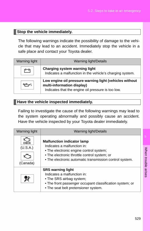
5
When trouble arises
5-2. Steps to take in an emergency
Stop the vehicle immediately.
The following warnings indicate the possibility of damage to the vehi-cle that may lead to an accident. Immediately stop the vehicle in asafe place and contact your Toyota dealer.
Have the vehicle inspected immediately.
Failing to investigate the cause of the following warnings may lead tothe system operating abnormally and possibly cause an accident.Have the vehicle inspected by your Toyota dealer immediately.
Warning light Warning light/Details
Charging system warning lightIndicates a malfunction in the vehicle’s charging system.
Low engine oil pressure warning light (vehicles without multi-information display)
Indicates that the engine oil pressure is too low.
Warning light Warning light/Details
(U.S.A.)
(Canada)
Malfunction indicator lampIndicates a malfunction in:• The electronic engine control system;• The electronic throttle control system; or• The electronic automatic transmission control system.
SRS warning lightIndicates a malfunction in:• The SRS airbag system;• The front passenger occupant classification system; or• The seat belt pretensioner system.
529

5-2. Steps to take in an emergency
(U.S.A.)
(Canada)
ABS warning lightIndicates a malfunction in:• The ABS; or• The brake assist system.
Electric power steering warning lightIndicates a malfunction in the EPS (Electric Power Steer-ing) system.
Slip indicator lightIndicates a malfunction in:• The Enhanced VSC system; • The TRAC system; • The hill-start assist control system; or• The downhill assist control system (4WD models).
(Flashes)
Cruise control indicator light (if equipped)Indicates a malfunction in the cruise control system.
■ If the malfunction indicator lamp comes on while drivingFirst check the following:
● Is the fuel tank low or empty?If it is, fill the fuel tank immediately.
● Is the fuel tank cap loose?If it is, tighten it securely.
The light will go off after taking several driving trips.If the light does not go off even after several trips, contact your Toyota dealeras soon as possible.
Warning light Warning light/Details
530

5
When trouble arises
5-2. Steps to take in an emergency
Follow the correction procedures.
After taking the specified steps to correct the suspected problem,check that the warning light turns off.
Warning light Warning light/Details Correction procedure
Open door warning light (warning buzzer)*1
Indicates that a door is not fully closed.
Check that all doors are closed.
Low fuel level warning light
Indicates that remaining fuel is about 2.2 gal. (8.3 L, 1.8 Imp. gal.) or less
Refuel the vehicle.
Driver’s seat beltreminder light(warning buzzer)*2
Warns the driver to fasten his/her seat belt.
Fasten the seat belt.
*3
*4
(On the center panel)
Front passenger’s seat belt reminder light(warning buzzer)*2
Warns the front passen-ger to fasten his or her seat belt.
Fasten the seat belt.
Automatic transmission fluid temperature warning light (vehicles without multi-information display)
Indicates that the auto-matic transmission fluid temperature is too high.
Stop the vehicle in a safe place and shift the shift lever to P.If the light does not go off, contact your Toyota dealer.
531

5-2. Steps to take in an emergency
Low washer fluid warning light (vehicles without multi-information display)
Low level of washer fluid
Fill the tank.
(U.S.A.)
Maintenance Required reminder light
Indicates that mainte-nance is required accord-ing to the driven distance on the maintenance schedule.*5
Illuminates for about 3 sec-onds and then flashes for about 15 seconds approxi-mately 4500 miles (7200 km) after the maintenance data has been reset.
If necessary, perform main-tenance.
Comes on and remains on if the distance driven exceeds 5000 miles (8000 km) after the maintenance data has been reset.(The indicator will not work properly unless the mainte-nance data has been reset.)
Perform the necessary maintenance.Please reset the mainte-nance data after the mainte-nance is performed. (→P. 447)
Warning light Warning light/Details Correction procedure
532

5
When trouble arises
5-2. Steps to take in an emergency
Tire pressure warning light
When the light comes on:Low tire inflation pressure such as• Natural causes (→P. 535)• Flat tire (→P. 540)
Adjust the tire inflation pressure (including the spare tire) to the specified level.
The light will turn off after a few minutes. In case the light does not turn off even if the tire inflation pressure is adjusted, have the system checked by your Toyota dealer.
When the light comes on after blinking for 1 minute:Malfunction in the tire pressure warning system (→P. 536)
Have the system checked by your Toyota dealer.
Master warning light (vehicles with multi-infor-mation display)
A buzzer sounds and the warning light comes on and flashes to indicate that the master warning system has detected a malfunc-tion.
→P. 539
Warning light Warning light/Details Correction procedure
533
5-2. Steps to take in an emergency
*1: Open door warning buzzer:
The open door warning buzzer sounds to alert one or more of the doors isnot fully closed (with the vehicle having reached a speed of 3 mph [5 km/h]).
*2: Driver's and front passenger’s seat belt reminders:
The driver’s and front passenger’s seat belt reminders sound to alert thedriver and front passenger that his or her seat belt is not fastened. Thesebuzzers sound for 10 seconds after the vehicle has reached a speed of atleast 12 mph (20 km/h). Then, if the seat belt is still unfastened, the buzzerwill sound in a different tone for 20 more seconds.
*3: Vehicles without navigation system*4: Vehicles with navigation system*5: Refer to the separate “Scheduled Maintenance Guide” or “Owner’s Manual
Supplement” for the maintenance interval applicable to your vehicle.
■Key reminder buzzer (vehicles without smart key system)The buzzer indicates that the key has not been removed with the engine offand the driver’s door opened.
■Open moon roof reminder buzzer (vehicles with multi-information dis-play)The buzzer indicates that the moon roof is not fully closed with the engine offand the driver’s door opened.
■Front passenger detection sensor and passenger seat belt reminder● If luggage is placed on the front passenger seat, the front passenger
detection sensor may cause the warning light to flash, even if a passen-ger is not sitting in the seat.
● If a cushion is placed on the seat, the sensor may not detect a passen-ger, and the warning light may not operate properly.
■Engine oil replacement reminder light (U.S.A. ⎯ vehicles without multi-information display)The engine oil replacement reminder light will come on and flash at approxi-mately 4500 miles (7200 km) after an oil change. When the distance drivenafter an oil change exceeds approximately 5000 miles (8000 km), the lightwill come on and remain on.
534
5
When trouble arises
5-2. Steps to take in an emergency
■When the tire pressure warning light comes onCheck the tire inflation pressure and adjust to the appropriate level.Pushing the tire pressure warning reset switch does not turn off the tirepressure warning light.
■The tire pressure warning light may turn on due to natural causesThe tire pressure warning light may turn on due to natural causes suchas natural air leaks or tire inflation pressure changes caused by temper-ature. In this case, adjusting the tire inflation pressure will turn off thewarning light (after a few minutes).
■When a tire is replaced with a spare tireThe spare tire is also equipped with the tire pressure warning valve andtransmitter. The tire pressure warning light will turn on if the tire inflationpressure of the spare tire is low. If a tire goes flat, even though the flattire is replaced with the spare tire, the tire pressure warning light doesnot turn off. Replace the spare tire with the repaired tire and adjust theproper tire inflation pressure. The tire pressure warning light will turn offafter a few minutes.
■ If the tire pressure warning system is inoperativeThe tire pressure warning system will be disabled in the following condi-tions:(When the condition becomes normal, the system will work properly.)● If tires not equipped with tire pressure warning valves and transmit-
ters are used.● If the ID code on the tire pressure warning valves and transmitters is
not registered in the tire pressure warning computer.● If the tire inflation pressure is 73 psi (500 kPa, 5.1 kgf/cm2 or bar) or
higher.
535

5-2. Steps to take in an emergency
The tire pressure warning system may be disabled in the following condi-tions:(When the condition becomes normal, the system will work properly.)● If electronic devices or facilities using similar radio wave frequencies
are nearby.● If a radio set at similar frequencies is in use in the vehicle.● If a window tint that affects the radio wave signals is installed.● If there is a lot of snow or ice on the vehicle, in particular around the
wheels or wheel housings.● If non-genuine Toyota wheels are used. (Even if you use Toyota
wheels, the tire pressure warning system may not work properly withsome types of tires.)
● If tire chains are used.● If the spare tire is in a location subject to poor radio wave signal
reception.● If a large metallic object which can interfere with signal reception is
put in the luggage room.■ If the tire pressure warning light frequently comes on after blinking
for 1 minuteVehicles without smart key system
If the tire pressure warning light comes on after blinking for 1 minute fre-quently when the engine switch is turned to the “ON” position, have itchecked by your Toyota dealer.
Vehicles with smart key systemIf the tire pressure warning light comes on after blinking for 1 minute fre-quently when the “ENGINE START STOP” switch is turned to IGNITIONON mode, have it checked by your Toyota dealer.
536

5
When trouble arises
5-2. Steps to take in an emergency
CAUTION
■ If the tire pressure warning light comes onBe sure to observe the following precautions. Failure to do so couldcause loss of vehicle control and result in death or serious injury.●Stop your vehicle in a safe place as soon as possible. Adjust the tire
inflation pressure immediately.● If the tire pressure warning light comes on even after tire inflation pres-
sure adjustment, it is probable that you have a flat tire. Check the tires.If the tire is flat, change to the spare tire and have the flat tire repairedby the nearest Toyota dealer.
●Avoid abrupt maneuvering and braking. If the vehicle tires deteriorate,you could lose control of the steering wheel or the brakes.
■ If a blowout or sudden air leakage should occurThe tire pressure warning system may not activate immediately.
■Maintenance of the tiresEach tire, including the spare (if provided), should be checked monthlywhen cold and inflated to the inflation pressure recommended by thevehicle manufacturer on the vehicle placard or tire inflation pressurelabel (tire and load information label). (If your vehicle has tires of a differ-ent size than the size indicated on the vehicle placard or tire inflationpressure label [tire and load information label], you should determine theproper tire inflation pressure for those tires.)As an added safety feature, your vehicle has been equipped with a tirepressure monitoring system (TPMS-tire pressure warning system) thatilluminates a low tire pressure telltale (tire pressure warning light) whenone or more of your tires is significantly under-inflated. Accordingly,when the low tire pressure telltale (tire pressure warning light) illumi-nates, you should stop and check your tires as soon as possible, andinflate them to the proper pressure. Driving on a significantly under-inflated tire causes the tire to overheat and can lead to tire failure.Under-inflation also reduces fuel efficiency and tire tread life, and mayaffect the vehicle's handling and stopping ability.
537
5-2. Steps to take in an emergency
CAUTION
Please note that the TPMS (tire pressure warning system) is not a sub-stitute for proper tire maintenance, and it is the driver's responsibility tomaintain correct tire pressure, even if under-inflation has not reached thelevel to trigger illumination of the TPMS low tire pressure telltale (tirepressure warning light).Your vehicle has also been equipped with a TPMS (tire pressure warningsystem) malfunction indicator to indicate when the system is not operat-ing properly. The TPMS (tire pressure warning system) malfunction indi-cator is combined with the low tire pressure telltale (tire pressurewarning light). When the system detects a malfunction, the telltale willflash for approximately one minute and then remain continuously illumi-nated. This sequence will continue upon subsequent vehicle start-ups aslong as the malfunction exists. When the malfunction indicator is illumi-nated, the system may not be able to detect or signal low tire pressureas intended.TPMS (tire pressure warning system) malfunctions may occur for a vari-ety of reasons, including the installation of replacement or alternate tiresor wheels on the vehicle that prevent the TPMS (tire pressure warningsystem) from functioning properly. Always check the TPMS (tire pres-sure warning system) malfunction telltale after replacing one or moretires or wheels on your vehicle to ensure that the replacement or alter-nate tires and wheels allow the TPMS (tire pressure warning system) tocontinue to function properly.
NOTICE
■Precaution when installing a different tireWhen a tire of a different specification or maker is installed, the tire pres-sure warning system may not operate properly.
538

5
When trouble arises
5-2. Steps to take in an emergency
If a warning message is displayed (vehicles with multi-information display)
■ Warning buzzerA buzzer may sound when a warning message is shown on themulti-information display.
■ If the warning message is shown again after its correctionprocedure has been performedContact your Toyota dealer as soon as possible.
The multi-information display shows warnings of system malfunc-tions or incorrectly performed operations. When a message isshown, perform corrections as indicated in the message.
Master warning lightThe master warning light also comes on or flashes in order to indicatethat a message is currently being displayed on the multi-informationdisplay.
Multi-information displayWarning messageCorrection procedure
539

5-2. Steps to take in an emergency
If you have a flat tire
Remove the flat tire and replace it with the spare provided.
■ Before jacking up the vehicle● Stop the vehicle on a hard, flat surface.
● Set the parking brake.
● Shift the shift lever to P.
● Stop the engine.
● Turn on the emergency flashers.
■ Location of the spare tire, jack and tools
Jack handleAdapter socket
Towing eyelet
Jack handleWheel nut wrench
Spare tire
Jack
540
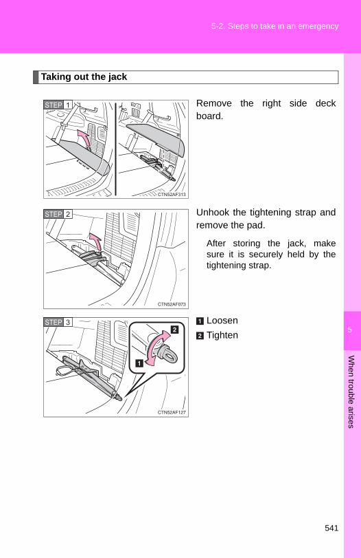
5
When trouble arises
5-2. Steps to take in an emergency
Taking out the jack
Remove the right side deckboard.
Unhook the tightening strap andremove the pad.
After storing the jack, makesure it is securely held by thetightening strap.
LoosenTighten
STEP 1
STEP 2
STEP 3
541
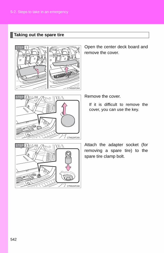
5-2. Steps to take in an emergency
Taking out the spare tire
Open the center deck board andremove the cover.
Remove the cover.
If it is difficult to remove thecover, you can use the key.
Attach the adapter socket (forremoving a spare tire) to thespare tire clamp bolt.
STEP 1
STEP 2
STEP 3
542

5
When trouble arises
5-2. Steps to take in an emergency
Assembling the jack handle.
Remove the jack handle andassemble it by following thesesteps.
Loosen the screw.Assemble the jack handle andtighten the screw.
Check that the screw is firmlytightened.
Connect the jack handle and theadapter socket. Turn the jackhandle.
The tire will be lowered com-pletely to the ground.
STEP 4
STEP 5
543

5-2. Steps to take in an emergency
Pull out the spare tire and standit against the bumper.
Remove the holding bracket.
STEP 6
STEP 7
544

5
When trouble arises
5-2. Steps to take in an emergency
Replacing a flat tire
Chock the tires.STEP 1STEP 1
Flat tireWheel chock
positions
Front
Left-hand side
Behind the rear right-hand side tire
Right-hand side
Behind the rear left-hand side tire
Rear
Left-hand side
In front of the front right-hand side tire
Right-hand side
In front of the front left-hand side tire
545
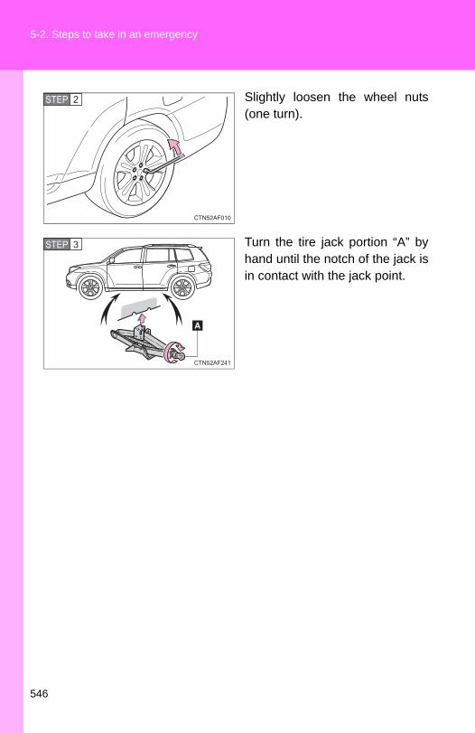
5-2. Steps to take in an emergency
Slightly loosen the wheel nuts(one turn).
Turn the tire jack portion “A” byhand until the notch of the jack isin contact with the jack point.
STEP 2
STEP 3
546

5
When trouble arises
5-2. Steps to take in an emergency
Raise the vehicle until the tire isslightly raised off the ground.
Remove all the wheel nuts andthe tire.
When resting the tire on theground, place the tire so that thewheel design faces up to avoidscratching the wheel surface.
STEP 4
STEP 5
547

5-2. Steps to take in an emergency
Installing the tire
Remove any dirt or foreign mat-ter from the wheel contact sur-face.
If foreign matter is on the wheelcontact surface, the wheel nutsmay loosen while the vehicle isin motion, and the tire maycome off the vehicle.
Install the tire and loosely tighteneach wheel nut by hand byapproximately the same amount.
Turn the nut washers until theycome into contact with the discwheel.
STEP 1
Disc wheel
Washer
STEP 2
548

5
When trouble arises
5-2. Steps to take in an emergency
Lower the vehicle.
Firmly tighten each nut two orthree times in the order shown inthe illustration.
Tightening torque:76 ft•lbf (103 N•m, 10.5 kgf•m)
STEP 3
STEP 4
549

5-2. Steps to take in an emergency
Stowing the flat tire, jack and all tools
Remove the center wheel ornament by pushing from thereverse side.
Put the flat tire on the groundwith the outer side facing up andinstall the holding bracket.
Be careful not to lose the wheelornament.
Turn the spare tire clamp bolt clockwise with a jack handleand adapter socket until you hear a click.Stow the jack and all tools.
STEP 1
STEP 2
■After completing the tire changeThe tire pressure warning system must be reset. (→P. 480)
STEP 3
STEP 4
550

5
When trouble arises
5-2. Steps to take in an emergency
CAUTION
■Using the tire jackImproper use of the tire jack may lead to death or serious injuries due tothe vehicle suddenly falling off the jack.●Do not use the tire jack for any purpose other than replacing tires or
installing and removing tire chains.●Only use the tire jack that comes with this vehicle for replacing a flat
tire.Do not use it on other vehicles, and do not use other tire jacks forreplacing tires on this vehicle.
●Always check that the tire jack is securely set to the jack point.●Do not put any part of your body under the vehicle supported by a jack.●Do not start or run the engine while your vehicle is supported by the
jack.●Do not raise the vehicle while someone is in it.●When raising the vehicle, do not put an object on or under the jack.●Do not raise the vehicle to a height greater than that required to
replace the tire.●Use a jack stand if it is necessary to get under the vehicle.Take particular care when lowering the vehicle to ensure that no oneworking on or near the vehicle will be injured.
551

5-2. Steps to take in an emergency
CAUTION
■Replacing a flat tireFailure to follow these precautions could cause the wheel nuts to loosenand the tire to fall off, resulting in death or serious injury.●Have the wheel nuts tightened with a torque wrench to 76 ft•lbf (103
N•m, 10.5 kgf•m) as soon as possible after changing wheels.●When installing the wheel nuts, be sure to install them with the tapered
ends facing inward. (→P. 491)■Replacing a flat tire for vehicles with power back door
In cases such as when replacing tires, make sure to turn off the powerback door main switch (→P. 62). Failure to do so may cause the backdoor to operate unintentionally if the power back door switch is acciden-tally touched, resulting in hands and fingers being caught and injured.
552

5
When trouble arises
5-2. Steps to take in an emergency
NOTICE
■Do not drive the vehicle with a flat tire.Do not continue driving with a flat tire.Driving even a short distance with a flat tire can damage the tire and thewheel beyond repair.
■When replacing the tiresWhen removing or fitting the wheels, tires or the tire pressure warningvalve and transmitter, contact your Toyota dealer as the tire pressurewarning valve and transmitter may be damaged if not handled correctly.
■To avoid damage to the tire pressure warning valves and transmit-tersWhen a tire is repaired with liquid sealants, the tire pressure warningvalve and transmitter may not operate properly. If a liquid sealant isused, contact your Toyota dealer or other qualified service shop as soonas possible. Make sure to replace the tire pressure warning valve andtransmitter when replacing the tire. (→P. 480)
■When stowing the flat tire●Ensure that there is no object caught between the tire and the vehicle
underbody.●Tighten the spare tire clamp bolt to hold the spare wheel carrier by the
hook securely.
553

5-2. Steps to take in an emergency
If the engine will not start
If the engine still does not start after following the correct startingprocedure (→P. 170, 174) or releasing the steering lock (→P. 172,175), confirm the following points.
■ The engine will not start even when the starter motor oper-ates normally.One of the following may be the cause of the problem.
● There may not be sufficient fuel in the vehicle’s tank.Refuel the vehicle.
● The engine may be flooded.Try to restart the engine once more following correct startingprocedures. (→P. 170, 174)
● There may be a malfunction in the engine immobilizer system(if equipped). (→P. 113)
■ The starter motor turns over slowly, the interior lights andheadlights are dim, or the horn does not sound or sounds ata low volume.One of the following may be the cause of the problem.
● The battery may be discharged. (→P. 560)
● The battery terminal connections may be loose or corroded.
■ The starter motor does not turn over (vehicles with smartkey system).The engine starting system may be malfunctioning due to anelectrical problem such as an open circuit or a blown fuse. How-ever, an interim measure is available to start the engine. (→P. 555)
554

5
When trouble arises
5-2. Steps to take in an emergency
Emergency start function (vehicles with smart key system)
When the engine does not start, the following steps can be used asan interim measure to start the engine if the “ENGINE START STOP”switch is functioning normally.
Set the parking brake.Shift the shift lever to P.Set the “ENGINE START STOP” switch to ACCESSORYmode.Push and hold the “ENGINE START STOP” switch about 15seconds while depressing the brake pedal firmly.
Even if the engine can be started using the above steps, the systemmay be malfunctioning. Have the vehicle checked by your Toyotadealer.
■ The starter motor does not turn over, the interior lights andheadlights do not turn on, or the horn does not sound.One of the following may be the cause of the problem.
● One or both of the battery terminals may be disconnected.
● The battery may be discharged. (→P. 560)
● There may be a malfunction in the steering lock system (vehi-cles with smart key system).
Contact your Toyota dealer if the problem cannot be repaired, or ifrepair procedures are unknown.
STEP 1
STEP 2
STEP 3
STEP 4
555

5-2. Steps to take in an emergency
If the shift lever cannot be shifted from P
If the shift lever cannot be shifted with your foot on the brake, theremay be a problem with the shift lock system (a system to preventaccidental operation of the shift lever). Have the vehicle inspected byyour Toyota dealer immediately.The following steps may be used as an emergency measure toensure that the shift lever can be shifted.
Set the parking brake.Vehicles without smart key system: Turn the engine switchto the “ACC” position.Vehicles with smart key system: Turn the “ENGINE STARTSTOP” switch to ACCESSORY mode.Depress the brake pedal.
Pry the cover up with a flat-head screwdriver or equiva-lent.
Press the shift lock overridebutton.
The shift lever can be shiftedwhile the button is pressed.
STEP 1
STEP 2
STEP 3
STEP 4
STEP 5
556

5
When trouble arises
5-2. Steps to take in an emergency
If you lose your keys/wireless remote control transmitter
■ KeysNew genuine keys can be made by your Toyota dealer. For vehicles with the smart key system, bring the other key andthe key number stamped on the key number plate. For vehicles without the smart key system, bring a master keyand the key number stamped on the key number plate.
■ Wireless remote control transmitter (vehicles without smartkey system)New genuine wireless remote control transmitters can be pur-chased and programmed by your Toyota dealer. If a wirelessremote control transmitter has been lost, bring the other wirelessremote control transmitter when going to pick up the new trans-mitter.
557
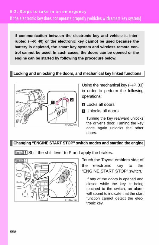
5-2. Steps to take in an emergency
If the electronic key does not operate properly (vehicles with smart key system)
Locking and unlocking the doors, and mechanical key linked functions
Using the mechanical key (→P. 33)in order to perform the followingoperations:
Locks all doorsUnlocks all doors
Turning the key rearward unlocksthe driver’s door. Turning the keyonce again unlocks the otherdoors.
Changing “ENGINE START STOP” switch modes and starting the engine
Shift the shift lever to P and apply the brakes.
Touch the Toyota emblem side ofthe electronic key to the“ENGINE START STOP” switch.
If any of the doors is opened andclosed while the key is beingtouched to the switch, an alarmwill sound to indicate that the startfunction cannot detect the elec-tronic key.
If communication between the electronic key and vehicle is inter-rupted (→P. 40) or the electronic key cannot be used because thebattery is depleted, the smart key system and wireless remote con-trol cannot be used. In such cases, the doors can be opened or theengine can be started by following the procedure below.
STEP 1
STEP 2
558

5
When trouble arises
5-2. Steps to take in an emergency
To change “ENGINE START STOP” switch modes: Within 5seconds of the buzzer sounding, release the brake pedal andpress the “ENGINE START STOP” switch. Modes can bechanged each time the switch is pressed. (→P. 171) To start the engine: Press the “ENGINE START STOP” switchwithin 5 seconds after the buzzer sounds, keeping the brakepedal depressed.
In the event that the “ENGINE START STOP” switch still cannot beoperated, contact your Toyota dealer.
■Stopping the engineShift the shift lever to P and press the “ENGINE START STOP” switch asyou normally do when stopping the engine.
■Replacing the electronic key batteryAs the above procedure is a temporary measure, it is recommended that theelectronic key battery be replaced immediately when the battery depletes.(→P. 497)
STEP 3
559

5-2. Steps to take in an emergency
If the battery is discharged
The following procedures may be used to start the engine if the vehi-cle's battery is discharged.You can call your Toyota dealer or qualified repair shop.
If you have a set of jumper (or booster) cables and a second vehi-cle with a 12-volt battery, you can jump start your Toyota followingthe steps below.
Connect the jumper cables.2.7 L 4-cylinder (1AR-FE) engine
STEP 1
560

5
When trouble arises
5-2. Steps to take in an emergency
3.5 L V6 (2GR-FE) engine
Positive (+) battery terminal on your vehiclePositive (+) battery terminal on the second vehicleNegative (-) battery terminal on the second vehicleConnect the jumper cable to ground on your vehicle as shown inthe illustration.
Start the engine of the second vehicle. Increase the enginespeed slightly and maintain at that level for approximately 5minutes to recharge the battery of your vehicle.Vehicles with smart key system: Open and close any of the doors with the “ENGINE STARTSTOP” switch OFF.
STEP 2
STEP 3
561
5-2. Steps to take in an emergency
■Starting the engine when the battery is dischargedThe engine cannot be started by push-starting.
■To prevent battery discharge●Turn off the headlights and the audio system while the engine is turned
off.
●Turn off any unnecessary electrical components when the vehicle is run-ning at a low speed for an extended period, such as in heavy traffic, etc.
■When the battery is removed or discharged●The power back door must be initialized (→P. 64)
●The tire inflation pressure warning system must be initialized. (→P. 480)
■Charging the batteryThe electricity stored in the battery will discharge gradually even when thevehicle is not in use, due to natural discharge and the draining effects of cer-tain electrical appliances. If the vehicle is left for a long time, the battery maydischarge, and the engine may be unable to start. (The battery rechargesautomatically during driving.)
Vehicles without smart key system: Maintain the engine speed of the second vehicle, and turnthe engine switch to the “ON” position, then start the vehi-cle's engine.Vehicles with smart key system: Maintain the engine speed of the second vehicle, and turnthe “ENGINE START STOP” switch to IGNITION ON mode,then start the vehicle's engine.Once the vehicle’s engine has started, remove the jumpercables in the exact reverse order in which they were con-nected.
Once the engine starts, have the vehicle checked at your Toyotadealer as soon as possible.
STEP 4
STEP 5
562
5
When trouble arises
5-2. Steps to take in an emergency
CAUTION
■Avoiding battery fires or explosionsObserve the following precautions to prevent accidentally igniting the flam-mable gas that may be emitted from the battery.
●Make sure the jumper cable is connected to the correct terminal and that itis not unintentionally in contact with any part other than the intended termi-nal.
●Do not allow the + and - clamps of the jumper cables to come into contactwith each other.
●Do not smoke, use matches, cigarette lighters or allow open flame nearthe battery.
■Battery precautionsThe battery contains poisonous and corrosive acidic electrolyte, whilerelated parts contain lead and lead compounds. Observe the following pre-cautions when handling the battery.
●When working with the battery, always wear safety glasses and take carenot to allow any battery fluids (acid) to come into contact with skin, clothingor the vehicle body.
●Do not lean over the battery.
● In the event that battery fluid comes into contact with the skin or eyes,immediately wash the affected area with water and seek medical attention.Place a wet sponge or cloth over the affected area until medical attentioncan be received.
●Always wash your hands after handling the battery support, terminals, andother battery-related parts.
●Do not allow children near the battery.
NOTICE
■When handling jumper cablesBe careful that the jumper cables do not become tangled in the cooling fanor any of the belts when connecting or disconnecting them.
563

5-2. Steps to take in an emergency
If your vehicle overheats
If your engine overheats:
Stop the vehicle in a safe place and turn off the air condi-tioning system.Check to see if steam is coming out from under the hood.If you see steam:
Stop the engine. Carefully lift the hood after the steamsubsides and then restart the engine.
If you do not see steam: Leave the engine running and carefully lift the hood.
Check to see if the cooling fans are operating.If the fans are operating:
Wait until the temperature of the engine (shown on theinstrument cluster) begins to fall and then stop theengine.
If the fans are not operating: Stop the engine and call your Toyota dealer.
After the engine has cooleddown sufficiently, check theengine coolant level andinspect the radiator core (radi-ator) for any leaks.
If the engine compartmentcover needs to be removed.(→P. 465)
Engine coolant reservoirRadiator
STEP 1
STEP 2
STEP 3
STEP 4
564

5
When trouble arises
5-2. Steps to take in an emergency
■OverheatingIf you observe the following, your vehicle may be overheating.
●The engine coolant temperature gauge enters the red zone or a loss ofpower is experienced.
●Steam comes from under the hood.
CAUTION
■To prevent an accident or injury when inspecting under the hood ofyour vehicle● If steam is seen coming from under the hood, do not open the hood until
the steam has subsided. The engine compartment may be very hot, caus-ing serious injury such as burns.
●Keep hands and clothing away from the fan and other belts while theengine is running.
●Do not loosen the coolant reservoir cap while the engine and radiator arehot.Serious injury, such as burns, may result from hot coolant and steamreleased under pressure.
Add engine coolant if neces-sary.
Water can be used in an emer-gency if engine coolant isunavailable. (→P. 580)
Have the vehicle checked at the nearest Toyota dealer as soon aspossible.
STEP 5
565

5-2. Steps to take in an emergency
NOTICE
■When adding engine coolantWait until the engine has cooled down before adding engine coolant.When adding coolant, do so slowly. Adding cool coolant to a hot engine tooquickly can cause damage to the engine.
566

5
When trouble arises
5-2. Steps to take in an emergency
If the vehicle becomes stuck
CAUTION
■When attempting to free a stuck vehicleIf you choose to rock the vehicle back and forth to free it, make sure the sur-rounding area is clear, to avoid striking other vehicles, objects or persons.The vehicle may also lunge forward or lunge back suddenly as it becomesfree. Use extreme caution.
■When shifting the shift leverBe careful not to shift the shift lever with the accelerator pedal depressed.This may lead to unexpected rapid acceleration of the vehicle that maycause an accident and result in death or serious injury.
Carry out the following procedures if the tires spin or the vehiclebecomes stuck in mud, dirt, or snow.
Stop the engine. Set the parking brake and put the shiftlever to P.Remove the mud, snow, or sand from around the stuck tire.Place wood, stones or some other material to help providetraction under the tires.Restart the engine.Shift the shift lever to the D or R position and carefully applythe accelerator to free the vehicle.Turn off TRAC and/or Enhanced VSC if these functions are ham-pering your attempts to free the vehicle. (→P. 224)
STEP 1
STEP 2
STEP 3
STEP 4
STEP 5
567

5-2. Steps to take in an emergency
NOTICE
■To avoid damaging the transmission and other components●Avoid spinning the wheels and do not rev the engine.
● If the vehicle remains stuck after trying these procedures, the vehicle mayrequire towing to be freed.
568

5
When trouble arises
5-2. Steps to take in an emergency
If your vehicle has to be stopped in an emergency
Only in an emergency, such as if it becomes impossible to stop thevehicle in the normal way, stop the vehicle using the following pro-cedure:
Steadily step on the brake pedal with both feet and firmlydepress it.Do not pump the brake pedal repeatedly as this will increase theeffort required to slow the vehicle.
Shift the shift lever to N.
If the shift lever is shifted to NAfter slowing down, stop the vehicle in a safe place by theroad.Stop the engine.
If the shift lever cannot be shifted to NKeep depressing the brake pedal with both feet to reducevehicle speed as much as possible.
Vehicles without a smart keysystem: Stop the engine byturning the engine switch tothe “ACC” position.
STEP 1
STEP 2
STEP 3
STEP 4
STEP 3
STEP 4
569
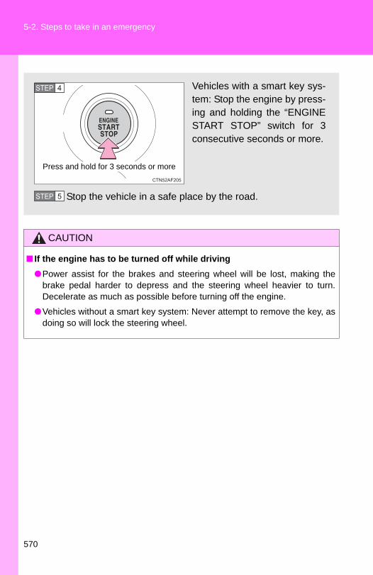
5-2. Steps to take in an emergency
CAUTION
■ If the engine has to be turned off while driving●Power assist for the brakes and steering wheel will be lost, making the
brake pedal harder to depress and the steering wheel heavier to turn.Decelerate as much as possible before turning off the engine.
●Vehicles without a smart key system: Never attempt to remove the key, asdoing so will lock the steering wheel.
Vehicles with a smart key sys-tem: Stop the engine by press-ing and holding the “ENGINESTART STOP” switch for 3consecutive seconds or more.
Stop the vehicle in a safe place by the road.
Press and hold for 3 seconds or more
STEP 4
STEP 5
570

6-1. Specifications
Maintenance data (fuel, oil level, etc.)
Dimensions and weights
*1: Without towing package
*2: With towing package
Overall length 188.4 in. (4785 mm)
Overall width 75.2 in. (1910 mm)
Overall height
Without roof rails68.1 in. (1730 mm)With roof rails69.3 in. (1760 mm)
Wheelbase 109.8 in. (2790 mm)
Front tread 64.0 in. (1625 mm)
Rear tread2WD models 64.2 in. (1630 mm)
4WD models 64.0 in. (1625 mm)
Vehicle capacity weight(Occupant + luggage) 1200 lb. (544 kg)
Trailer Weight Rat-ing (Trailer weight + cargo)
2.7 L 4-cylin-der (1AR-FE) engine
1500 lb. (680 kg)*1
3500 lb. (1500 kg)*2
3.5 L V6 (2GR-FE) engine
2000 lb. (900 kg)*1
5000 lb. (2000 kg)*2
572

6-1. Specifications
6
Vehicle specifications
Vehicle identification
■ Vehicle identification numberThe vehicle identification number (VIN) is the legal identifier for yourvehicle. This is the primary identification number for your Toyota. It isused in registering the ownership of your vehicle.
This number is also stamped onthe top left of the instrumentpanel.
■ Certification LabelThis number is also on the Certi-fication Label on the driver’s sidecenter pillar.
573
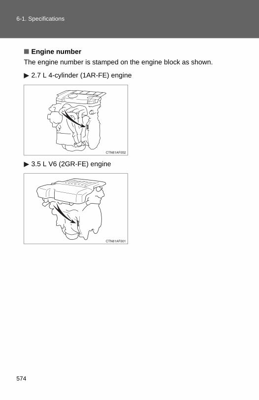
6-1. Specifications
■ Engine numberThe engine number is stamped on the engine block as shown.
2.7 L 4-cylinder (1AR-FE) engine
3.5 L V6 (2GR-FE) engine
574

6-1. Specifications
6
Vehicle specifications
Engine
Fuel
Model 1AR-FE 2GR-FE
Type 4-cylinder in line, 4-cycle, gasoline
6-cylinder V type, 4-cycle, gasoline
Bore and stroke 3.54 × 4.13 in. (90.0 × 105.0 mm)
3.70 × 3.27 in. (94.0 × 83.0 mm)
Displacement 163.1 cu.in. (2672 cm3) 210.9 cu.in. (3456 cm3)
Drive belt tension Automatic adjustment
Fuel type Unleaded gasoline only
Octane rating 87 (Research Octane Number 91) or higher
Fuel tank capacity(Reference) 19.2 gal. (72.5 L, 15.9 Imp. gal.)
575

6-1. Specifications
Lubrication system (2.7 L 4-cylinder [1AR-FE] engine)
*: The engine oil capacity is a reference quantity to be used when exchanging.Warm up and turn off the engine, wait more than 5 minutes, and check the oillevel on the dipstick.
■ Engine oil selection“Toyota Genuine Motor Oil” is used in your Toyota vehicle. UseToyota approved “Toyota Genuine Motor Oil” or equivalent to satisfythe following grade and viscosity.
Oil grade: ILSAC multigrade engine oil
Recommended viscosity: SAE 5W-20 or 0W-20
SAE 5W-20 or 0W-20 engine oilmay be used. However, SAE0W-20 is the best choice forgood fuel economy and goodstarting in cold weather.
Oil viscosity (0W-20 is explained here as an example):
● The 0W in 0W-20 indicates the characteristic of the oil which allowscold startability. Oils with a lower value before the W allow for easierstarting of the engine in cold weather.
● The 20 in 0W-20 indicates the viscosity characteristic of the oil whenthe oil is at high temperature. An oil with a higher viscosity (one with ahigher value) may be better suited if the vehicle is operated at highspeeds, or under extreme load conditions.
Oil capacity(Drain and refill ⎯ reference*)
Without filter
With filter
4.2 qt. (4.0 L, 3.5 Imp. qt.)
4.6 qt. (4.4 L, 3.9 Imp. qt.)
Outside temperature
576

6-1. Specifications
6
Vehicle specifications
How to read oil container label:
The ILSAC (International Lubricant Standardization and ApprovalCommittee) Certification Mark is added to some oil containers to helpyou select the oil you should use.
577

6-1. Specifications
Lubrication system (3.5 L V6 [2GR-FE] engine)
■ Engine oil selection“Toyota Genuine Motor Oil” is used in your Toyota vehicle. UseToyota approved “Toyota Genuine Motor Oil” or equivalent to satisfythe following grade and viscosity.
Oil grade: ILSAC multigrade engine oil
Recommended viscosity: SAE 0W-20
SAE 0W-20 is the best choice forgood fuel economy and goodstarting in cold weather.
If SAE 0W-20 is not available,SAE 5W-20 oil may be used.However, it must be replacedwith SAE 0W-20 at the next oilchange.
Oil viscosity (0W-20 is explained here as an example):
● The 0W in 0W-20 indicates the characteristic of the oil which allowscold startability. Oils with a lower value before the W allow for easierstarting of the engine in cold weather.
● The 20 in 0W-20 indicates the viscosity characteristic of the oil whenthe oil is at high temperature. An oil with a higher viscosity (one with ahigher value) may be better suited if the vehicle is operated at highspeeds, or under extreme load conditions.
Oil capacity(Drain and refill ⎯ reference)
Without filter
With filter
6.0 qt. (5.7 L, 5.0 Imp. qt.)
6.4 qt. (6.1 L, 5.4 Imp. qt.)
Outside temperature
578

6-1. Specifications
6
Vehicle specifications
How to read oil container label:
The ILSAC (International Lubricant Standardization and ApprovalCommittee) Certification Mark is added to some oil containers to helpyou select the oil you should use.
579

6-1. Specifications
Cooling system
*: With towing package
Capacity (Reference)
2.7 L 4-cylin-der (1AR-FE) engine
Without rear air conditioning system7.3 qt. (6.9 L, 6.1 Imp. qt.)8.0 qt. (7.6 L, 6.7 Imp. qt.)*With rear air conditioning system9.6 qt. (9.1 L, 8.0 Imp. qt.)10.4 qt. (9.8 L, 8.6 Imp. qt.)*
3.5 L V6 (2GR-FE) engine
Without rear air conditioning system9.3 qt. (8.8 L, 7.7 Imp. qt.)10.0 qt. (9.5 L, 8.4 Imp. qt.)*With rear air conditioning system11.6 qt. (11.0 L, 9.7 Imp. qt.)12.4 qt. (11.7 L, 10.3 Imp. qt.)*
Coolant type
Use either of the following.• “Toyota Super Long Life Coolant” • Similar high-quality ethylene glycol-based
non-silicate, non-amine, non-nitrite, and non-borate coolant with long-life hybrid organic acid technology
Do not use plain water alone.
580

6-1. Specifications
6
Vehicle specifications
Ignition system
Electrical system
Spark plug Make
Gap
2.7 L 4-cylinder (1AR-FE) engineDENSO, SK16HR113.5 L V6 (2GR-FE) engineDENSO FK20HR11
0.043 in. (1.1 mm)
NOTICE
■ Iridium-tipped spark plugsUse only iridium-tipped spark plugs. Do not adjust gap when tuning engine.
Battery
Open voltage* at 68°F (20°C):
12.6 ⎯ 12.8 V Fully charged12.2 ⎯ 12.4 V Half charged11.8 ⎯ 12.0 V Discharged(*: Voltage is checked 20 minutes after the engine and all the lights are turned off)
Charging rates 5 A max.
581

6-1. Specifications
Rear differential (4WD models)
Automatic transaxle
*: The fluid capacity is a reference quantity. If replacement is necessary, con-tact your Toyota dealer.
Oil capacity 1.0 qt. (0.9 L, 0.8 Imp. qt.)
Oil type Hypoid gear oil API GL-5
Recommended oil viscosity Above 0°F (-18°C): SAE 90Below 0°F (-18°C): SAE 80W or 80W-90
Fluid capacity*
2.7 L 4-cylinder (1AR-FE) engine 6.9 qt. (6.5 L, 5.7 Imp. qt.)3.5 L V6 (2GR-FE) engine 2WD models: 9.3 qt. (8.8 L, 7.7 Imp. qt.)4WD models: 9.5 qt. (9.0 L, 7.9 Imp. qt.)
Fluid type Toyota Genuine ATF WS
NOTICE
■Automatic transmission fluid typeUsing automatic transmission fluid other than “Toyota Genuine ATF WS”may cause deterioration in shift quality, locking up of your transmissionaccompanied by vibration, and ultimately damage the automatic transmis-sion of your vehicle.
582
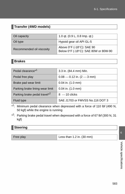
6-1. Specifications
6
Vehicle specifications
Transfer (4WD models)
Brakes
*1: Minimum pedal clearance when depressed with a force of 110 lbf (490 N,50 kgf) while the engine is running
*2: Parking brake pedal travel when depressed with a force of 67 lbf (300 N, 31kgf)
Steering
Oil capacity 1.0 qt. (0.9 L, 0.8 Imp. qt.)
Oil type Hypoid gear oil API GL-5
Recommended oil viscosity Above 0°F (-18°C): SAE 90Below 0°F (-18°C): SAE 80W or 80W-90
Pedal clearance*1 3.3 in. (84.4 mm) Min.
Pedal free play 0.08 ⎯ 0.12 in. (2 ⎯ 3 mm)
Brake pad wear limit 0.04 in. (1.0 mm)
Parking brake lining wear limit 0.04 in. (1.0 mm)
Parking brake pedal travel*2 8 ⎯ 10 clicks
Fluid type SAE J1703 or FMVSS No.116 DOT 3
Free play Less than 1.2 in. (30 mm)
583

6-1. Specifications
Tires and wheels
Type A
Tire size P245/65R17 105S
Tire inflation pressure(Recommended cold tire inflation pressure)
Driving under normal conditionsFront:30 psi (210 kPa, 2.1 kgf/cm2 or bar)Rear:30 psi (210 kPa, 2.1 kgf/cm2 or bar)Spare: 30 psi (210 kPa, 2.1 kgf/cm2 or bar)
Driving at high speeds above 100 mph (160 km/h) (in countries where such speeds are permitted by law)
Add 5 psi (30 kPa, 0.3 kgf/cm2 or bar) to the front tires and rear tires. Never exceed the maximum cold tire inflation pressure indi-cated on the tire sidewall.
Wheel size 17 × 7 1/2 J
Wheel nut torque 76 ft•lbf (103 N•m, 10.5 kgf•m)
584
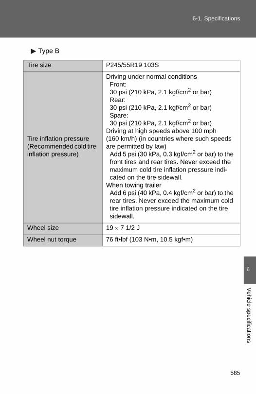
6-1. Specifications
6
Vehicle specifications
Type B
Tire size P245/55R19 103S
Tire inflation pressure(Recommended cold tire inflation pressure)
Driving under normal conditionsFront:30 psi (210 kPa, 2.1 kgf/cm2 or bar)Rear:30 psi (210 kPa, 2.1 kgf/cm2 or bar)Spare: 30 psi (210 kPa, 2.1 kgf/cm2 or bar)
Driving at high speeds above 100 mph (160 km/h) (in countries where such speeds are permitted by law)
Add 5 psi (30 kPa, 0.3 kgf/cm2 or bar) to the front tires and rear tires. Never exceed the maximum cold tire inflation pressure indi-cated on the tire sidewall.
When towing trailerAdd 6 psi (40 kPa, 0.4 kgf/cm2 or bar) to the rear tires. Never exceed the maximum cold tire inflation pressure indicated on the tire sidewall.
Wheel size 19 × 7 1/2 J
Wheel nut torque 76 ft•lbf (103 N•m, 10.5 kgf•m)
585

6-1. Specifications
Light bulbs
A: H11 halogen bulbs B: Wedge base bulbs (amber)C: HB3 halogen bulbs D: Wedge base bulbs (clear)E: PSX26W F: Double end bulbs
*: If equipped
Light Bulbs Bulb No. W Type
Exterior
Headlights High beam Low beam
9005⎯
6055
CA
Parking, front side marker and front turn signal lights 3457NA 28/8 B
Fog lights* ⎯ 24 E
Rear turn signal lights ⎯ 21 B
Back-up lights 921 16 D
Stop/tail and rear side marker lights 7443 21/5 D
License plate lights ⎯ 5 D
Outer foot lights* ⎯ 5 D
Interior
Vanity lights ⎯ 8 D
Personal/interior lights (front) ⎯ 5 D
Personal lights (center)* ⎯ 5 D
Interior lights (center*/rear) ⎯ 8 F
Door courtesy lights 168 5 D
586

6
Vehicle specifications
6-1. Specifications
Fuel information
■Fuel tank opening for unleaded gasolineTo help prevent incorrect fueling, your Toyota has a fuel tank opening thatonly accommodates the special nozzle on unleaded fuel pumps.
■ If your engine knocks●Consult your Toyota dealer.
●You may occasionally notice light knocking for a short time while acceler-ating or driving uphill. This is normal and there is no need for concern.
■Gasoline qualityIn very few cases, driveability problems may be caused by the brand of gas-oline you are using. If driveability problems persist, try changing the brand ofgasoline. If this does not correct the problem, consult your Toyota dealer.
■Gasoline quality standards●Automotive manufacturers in the US, Europe and Japan have developed
a specification for fuel quality called the World-Wide Fuel Charter(WWFC) that is expected to be applied worldwide.
●The WWFC consists of four categories that are based on required emis-sion levels. In the US, category 4 has been adopted.
●The WWFC improves air quality by lowering emissions in vehicle fleets,and customer satisfaction through better performance.
Your vehicle must use only unleaded gasoline.Select octane rating 87 (Research Octane Number 91) or higher. Useof unleaded gasoline with an octane rating lower than 87 may resultin engine knocking. Persistent knocking can lead to engine damage.
At minimum, the gasoline you use should meet the specificationsof ASTM D4814 in the U.S.A. and CGSB3.5-M93 in Canada.
587
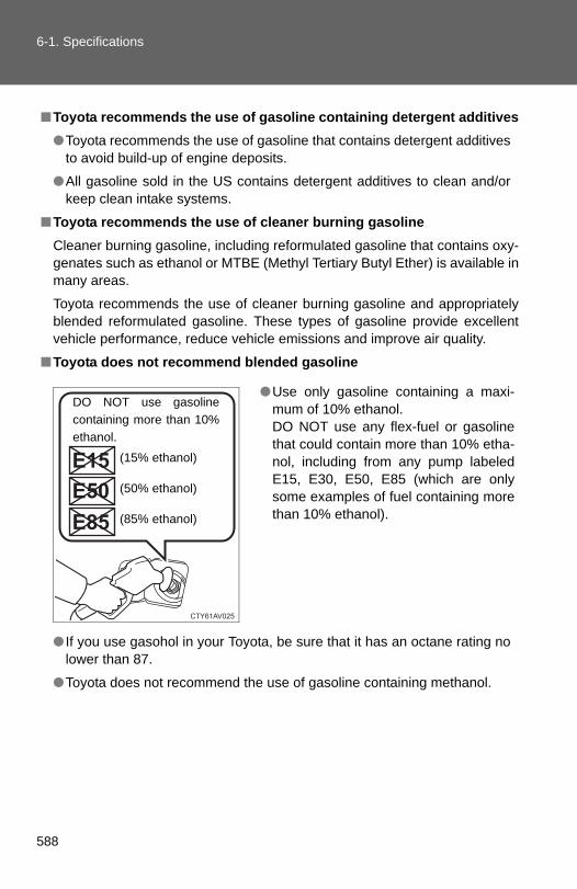
6-1. Specifications
■Toyota recommends the use of gasoline containing detergent additives●Toyota recommends the use of gasoline that contains detergent additives
to avoid build-up of engine deposits.
●All gasoline sold in the US contains detergent additives to clean and/orkeep clean intake systems.
■Toyota recommends the use of cleaner burning gasolineCleaner burning gasoline, including reformulated gasoline that contains oxy-genates such as ethanol or MTBE (Methyl Tertiary Butyl Ether) is available inmany areas.
Toyota recommends the use of cleaner burning gasoline and appropriatelyblended reformulated gasoline. These types of gasoline provide excellentvehicle performance, reduce vehicle emissions and improve air quality.
■Toyota does not recommend blended gasoline
● If you use gasohol in your Toyota, be sure that it has an octane rating nolower than 87.
●Toyota does not recommend the use of gasoline containing methanol.
●Use only gasoline containing a maxi-mum of 10% ethanol. DO NOT use any flex-fuel or gasolinethat could contain more than 10% etha-nol, including from any pump labeledE15, E30, E50, E85 (which are onlysome examples of fuel containing morethan 10% ethanol).
DO NOT use gasolinecontaining more than 10%ethanol.
(15% ethanol)
(50% ethanol)
(85% ethanol)
588

6-1. Specifications
6
Vehicle specifications
■Toyota does not recommend gasoline containing MMTSome gasoline contains octane enhancing additive called MMT (Methylcy-clopentadienyl Manganese Tricarbonyl).
Toyota does not recommend the use of gasoline that contains MMT. If fuelcontaining MMT is used, your emission control system may be adverselyaffected.
The malfunction indicator lamp on the instrument cluster may come on. Ifthis happens, contact your Toyota dealer for service.
NOTICE
■Notice on fuel quality●Do not use improper fuels. If improper fuels are used the engine will be
damaged.
●Do not use leaded gasoline.Leaded gasoline will cause the three-way catalytic converter to lose itseffectiveness and the emission control system to function improperly.
●Do not use gasohol other than that stated here.Other gasohol may cause fuel system damage or vehicle performanceproblems.
■Fuel-related poor driveabilityIf after using a different type of fuel, poor driveability is encountered (poorhot starting, vaporization, engine knocking, etc.), discontinue the use of thattype of fuel.
■When refueling with gasoholTake care not to spill gasohol. It can damage your vehicle's paint.
589
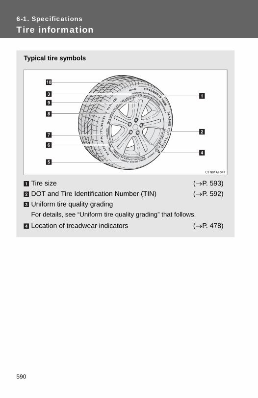
6-1. Specifications
Tire information
Typical tire symbols
Tire size (→P. 593)DOT and Tire Identification Number (TIN) (→P. 592)Uniform tire quality gradingFor details, see “Uniform tire quality grading” that follows.
Location of treadwear indicators (→P. 478)
590

6-1. Specifications
6
Vehicle specifications
Tire ply composition and materialsPlies are layers of rubber-coated parallel cords. Cords are thestrands which form the plies in a tire.
Radial tires or bias-ply tiresA radial tire has “RADIAL” on the sidewall. A tire not marked“RADIAL” is a bias-ply tire.
TUBELESS or TUBE TYPEA tubeless tire does not have a tube and air is directly filled in thetire. A tube type tire has a tube inside the tire and the tube main-tains the air pressure.
Load limit at maximum cold tire inflation pressure (→P. 482)Maximum cold tire inflation pressure (→P. 584)This means the pressure to which a tire may be inflated.
Summer tire or all season tire (→P. 483)An all season tire has “M+S” on the sidewall. A tire not marked“M+S” is a summer tire.
591

6-1. Specifications
Typical DOT and tire identification number (TIN)
DOT symbol*Tire Identification Number(TIN)Tire manufacturer's identifica-tion markTire size codeManufacturer's optional tiretype code (3 or 4 letters)Manufacturing weekManufacturing year
*: The DOT symbol certifies thatthe tire conforms to applicableFederal Motor Vehicle SafetyStandards.
592

6-1. Specifications
6
Vehicle specifications
Tire size
■ Typical tire size informationThe illustration indicates typicaltire size.
Tire use(P = Passenger car, T = Temporary use)Section width (millimeters)Aspect ratio(tire height to section width)Tire construction code (R = Radial, D = Diagonal)Wheel diameter (inches)Load index (2 digits or 3 digits)Speed symbol (alphabet with one letter)
■ Tire dimensionsSection widthTire heightWheel diameter
593
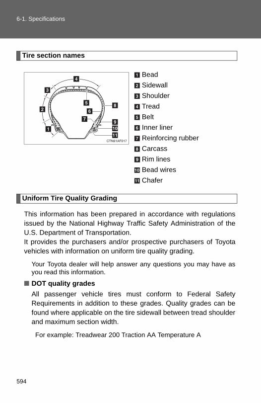
6-1. Specifications
Tire section names
BeadSidewallShoulderTreadBeltInner linerReinforcing rubberCarcassRim linesBead wiresChafer
Uniform Tire Quality Grading
This information has been prepared in accordance with regulationsissued by the National Highway Traffic Safety Administration of theU.S. Department of Transportation.It provides the purchasers and/or prospective purchasers of Toyotavehicles with information on uniform tire quality grading.
Your Toyota dealer will help answer any questions you may have asyou read this information.
■ DOT quality gradesAll passenger vehicle tires must conform to Federal SafetyRequirements in addition to these grades. Quality grades can befound where applicable on the tire sidewall between tread shoulderand maximum section width.
For example: Treadwear 200 Traction AA Temperature A
594

6-1. Specifications
6
Vehicle specifications
■ TreadwearThe treadwear grade is a comparative rating based on the wearrate of the tire when tested under controlled conditions on a speci-fied government test course.
For example, a tire graded 150 would wear one and a half (1 - 1/2)times as well on the government course as a tire graded 100.The relative performance of tires depends upon the actual conditionsof their use, however, and may depart significantly from the norm dueto variations in driving habits, service practices and differences inroad characteristics and climate.
■ Traction AA, A, B, CThe traction grades, from highest to lowest, are AA, A, B and C,and they represent the tire's ability to stop on wet pavement asmeasured under controlled conditions on specified governmenttest surfaces of asphalt and concrete.
A tire marked C may have poor traction performance.
Warning: The traction grade assigned to this tire is based on braking(straight ahead) traction tests and does not include cornering (turn-ing) traction.
■ Temperature A, B, CThe temperature grades are A (the highest), B, and C, represent-ing the tire's resistance to the generation of heat and its ability todissipate heat when tested under controlled conditions on a speci-fied indoor laboratory test wheel.
Sustained high temperature can cause the material of the tire todegenerate and reduce tire life, and excessive temperature can leadto sudden tire failure.
The grade C corresponds to a level of performance which all passen-ger car tires must meet under the Federal Motor Vehicle Safety Stan-dard No. 109.
Grades B and A represent higher levels of performance on the labo-ratory test wheel than the minimum required by law.
595
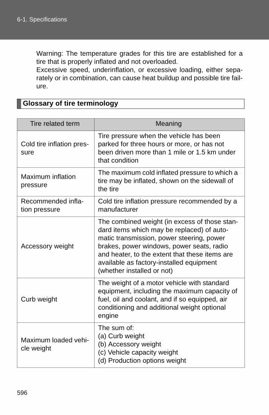
6-1. Specifications
Warning: The temperature grades for this tire are established for atire that is properly inflated and not overloaded.Excessive speed, underinflation, or excessive loading, either sepa-rately or in combination, can cause heat buildup and possible tire fail-ure.
Glossary of tire terminology
Tire related term Meaning
Cold tire inflation pres-sure
Tire pressure when the vehicle has been parked for three hours or more, or has not been driven more than 1 mile or 1.5 km under that condition
Maximum inflation pressure
The maximum cold inflated pressure to which a tire may be inflated, shown on the sidewall of the tire
Recommended infla-tion pressure
Cold tire inflation pressure recommended by a manufacturer
Accessory weight
The combined weight (in excess of those stan-dard items which may be replaced) of auto-matic transmission, power steering, power brakes, power windows, power seats, radio and heater, to the extent that these items are available as factory-installed equipment (whether installed or not)
Curb weight
The weight of a motor vehicle with standard equipment, including the maximum capacity of fuel, oil and coolant, and if so equipped, air conditioning and additional weight optional engine
Maximum loaded vehi-cle weight
The sum of:(a) Curb weight(b) Accessory weight(c) Vehicle capacity weight(d) Production options weight
596

6-1. Specifications
6
Vehicle specifications
Tire related term Meaning
Normal occupant weight
150 lb. (68 kg) times the number of occupants specified in the second column of Table 1* that follows
Occupant distribution Distribution of occupants in a vehicle as speci-fied in the third column of Table 1* below
Production options weight
The combined weight of installed regular pro-duction options weighing over 5 lb. (2.3 kg) in excess of the standard items which they replace, not previously considered in curb weight or accessory weight, including heavy duty brakes, ride levelers, roof rack, heavy duty 12-volt battery, and special trim
Rim A metal support for a tire or a tire and tube assembly upon which the tire beads are seated
Rim diameter(Wheel diameter) Nominal diameter of the bead seat
Rim size designation Rim diameter and width
Rim type designation The industry manufacturer's designation for a rim by style or code
Rim width Nominal distance between rim flanges
Vehicle capacity weight (Total load capacity)
The rated cargo and luggage load plus 150 lb. (68 kg) times the vehicle's designated seating capacity
Vehicle maximum load on the tire
The load on an individual tire that is determined by distributing to each axle its share of the maximum loaded vehicle weight, and dividing by two
Vehicle normal load on the tire
The load on an individual tire that is determined by distributing to each axle its share of curb weight, accessory weight, and normal occu-pant weight (distributed in accordance with Table 1* below), and dividing by two
597

6-1. Specifications
Tire related term Meaning
Weather side The surface area of the rim not covered by the inflated tire
BeadThe part of the tire that is made of steel wires, wrapped or reinforced by ply cords and that is shaped to fit the rim
Bead separation A breakdown of the bond between components in the bead
Bias ply tire
A pneumatic tire in which the ply cords that extend to the beads are laid at alternate angles substantially less than 90 degrees to the cen-terline of the tread
Carcass The tire structure, except tread and sidewall rubber which, when inflated, bears the load
Chunking The breaking away of pieces of the tread or sidewall
Cord The strands forming the plies in the tire
Cord separation The parting of cords from adjacent rubber com-pounds
Cracking Any parting within the tread, sidewall, or inner-liner of the tire extending to cord material
CT
A pneumatic tire with an inverted flange tire and rim system in which the rim is designed with rim flanges pointed radially inward and the tire is designed to fit on the underside of the rim in a manner that encloses the rim flanges inside the air cavity of the tire
Extra load tireA tire designed to operate at higher loads and at higher inflation pressures than the corre-sponding standard tire
Groove The space between two adjacent tread ribs
InnerlinerThe layer(s) forming the inside surface of a tubeless tire that contains the inflating medium within the tire
598

6-1. Specifications
6
Vehicle specifications
Tire related term Meaning
Innerliner separation The parting of the innerliner from cord material in the carcass
Intended outboard sidewall
(a) The sidewall that contains a whitewall, bears white lettering, or bears manufac-turer, brand, and/or model name molding that is higher or deeper than the same molding on the other sidewall of the tire, or
(b) The outward facing sidewall of an asym-metrical tire that has a particular side that must always face outward when mounted on a vehicle
Light truck (LT) tireA tire designated by its manufacturer as prima-rily intended for use on lightweight trucks or multipurpose passenger vehicles
Load rating The maximum load that a tire is rated to carry for a given inflation pressure
Maximum load rating The load rating for a tire at the maximum per-missible inflation pressure for that tire
Maximum permissible inflation pressure
The maximum cold inflation pressure to which a tire may be inflated
Measuring rim The rim on which a tire is fitted for physical dimension requirements
Open splice Any parting at any junction of tread, sidewall, or innerliner that extends to cord material
Outer diameter The overall diameter of an inflated new tire
Overall width
The linear distance between the exteriors of the sidewalls of an inflated tire, including eleva-tions due to labeling, decorations, or protective bands or ribs
Passenger car tire
A tire intended for use on passenger cars, mul-tipurpose passenger vehicles, and trucks, that have a gross vehicle weight rating (GVWR) of 10000 lb. or less.
599
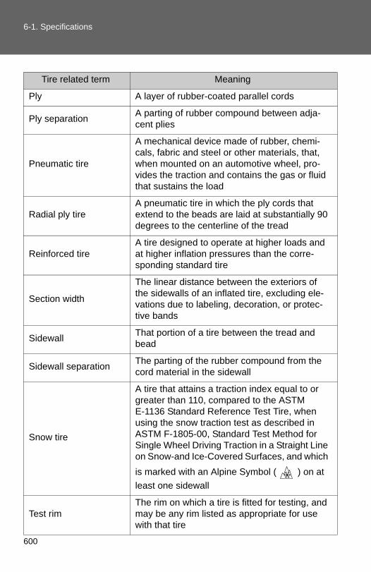
6-1. Specifications
Tire related term Meaning
Ply A layer of rubber-coated parallel cords
Ply separation A parting of rubber compound between adja-cent plies
Pneumatic tire
A mechanical device made of rubber, chemi-cals, fabric and steel or other materials, that, when mounted on an automotive wheel, pro-vides the traction and contains the gas or fluid that sustains the load
Radial ply tireA pneumatic tire in which the ply cords that extend to the beads are laid at substantially 90 degrees to the centerline of the tread
Reinforced tire A tire designed to operate at higher loads and at higher inflation pressures than the corre-sponding standard tire
Section width
The linear distance between the exteriors of the sidewalls of an inflated tire, excluding ele-vations due to labeling, decoration, or protec-tive bands
Sidewall That portion of a tire between the tread and bead
Sidewall separation The parting of the rubber compound from the cord material in the sidewall
Snow tire
A tire that attains a traction index equal to or greater than 110, compared to the ASTM E-1136 Standard Reference Test Tire, when using the snow traction test as described in ASTM F-1805-00, Standard Test Method for Single Wheel Driving Traction in a Straight Line on Snow-and Ice-Covered Surfaces, and which is marked with an Alpine Symbol ( ) on at least one sidewall
Test rimThe rim on which a tire is fitted for testing, and may be any rim listed as appropriate for use with that tire
600

6-1. Specifications
6
Vehicle specifications
*: Table 1 ⎯ Occupant loading and distribution for vehicle normal loadfor various designated seating capacities
Tire related term Meaning
Tread That portion of a tire that comes into contact with the road
Tread rib A tread section running circumferentially around a tire
Tread separation Pulling away of the tread from the tire carcass
Treadwear indicators (TWI)
The projections within the principal grooves designed to give a visual indication of the degrees of wear of the tread
Wheel-holding fixture The fixture used to hold the wheel and tire assembly securely during testing
Designated seating capacity, Number of
occupants
Vehicle normal load, Number of occupants
Occupant distribution in a normally loaded vehi-
cle
2 through 4 2 2 in front
5 through 10 3 2 in front, 1 in second seat
11 through 15 52 in front, 1 in second seat, 1 in third seat, 1
in fourth seat
16 through 20 72 in front, 2 in second seat, 2 in third seat, 1
in fourth seat
601

6-2. Customization
Customizable features
Item Function Default setting Customizedsetting
Door lock (→P. 54, 558)
Speed-detecting auto-matic door lock function Off On
Opening driver's door unlocks all doors Off On
Shifting gears to a P unlocks all doors On Off
Shifting gears to posi-tion other than P locks all doors
On Off
Unlocking using a key
Driver's door unlocked in one step, all doors
unlocked in two steps
All doors unlocked in one
step
Smart key system (→P. 35)
Smart key system On Off
Operation signal (Emergency flashers) On Off
Your vehicle includes a variety of electronic features that can bepersonalized to your preferences. Programming these preferencesrequires specialized equipment and may be performed by yourToyota dealer.
Some function settings are changed simultaneously with other functionsbeing customized. Contact your Toyota dealer.
602

6-2. Customization
6
Vehicle specifications
Wireless remote con-trol (→P. 48)
Wireless remote control On Off
Unlocking operation
Driver's door unlocked in one step, all doors
unlocked in two steps
All doors unlocked in one
step
Automatic door lock function to be activated if door is not opened after being unlocked
On Off
Time elapsed before automatic door lock function is activated if door is not opened after being unlocked
60 seconds
30 seconds
120 seconds
Operation signal (Emergency flashers) On Off
Door lock buzzer On Off
Operation signal (Buzzer) On Off
Panic function On Off
Glass hatch opening operation Push and hold
Push twice
One short push
Item Function Default setting Customizedsetting
603

6-2. Customization
Automatic light control system (→P. 200)
Light sensor sensitivity Level 3 Level 1 to 5
Time elapsed before headlights automati-cally turn off after doors are closed
30 seconds
0 seconds
60 seconds
90 seconds
Ambient light level at which instrument illumi-nation begins to dim (meter light etc.)
Standard -2 (darker) to 2 (brighter)
Ambient light level at which instrument illumi-nation begins to brighten (meter light etc.)
Standard -2 (darker) to 2 (brighter)
Lights (→P. 200)
Daytime running light system (U.S.A. only) On Off
Multi-infor-mation dis-play(→P. 191)
Language selection English
French
Spanish
Chinese
Illumination(→P. 396)
Time elapsed before lights turn off 15 seconds
7.5 seconds
30 seconds
Operation when the doors are unlocked On Off
Operation after the “ENGINE START STOP” switch or the engine switch is turned OFF
On Off
Item Function Default setting Customizedsetting
604

6-2. Customization
6
Vehicle specifications
Outer foot lights(if equipped)(→P. 396)
Operation when you approach the vehicle with the electronic key on your person
On Off
Operation when the doors are unlocked using the wireless remote control, key or entry function
On Off
Operation when the doors are unlocked using the door lock function
On Off
Time period before lights turn off 15 seconds
7.5 seconds
30 seconds
Lighting control On Off
Item Function Default setting Customizedsetting
605

Reporting safety defects for U.S. owners
If you believe that your vehicle has a defect which could cause acrash or could cause injury or death, you should immediatelyinform the National Highway Traffic Safety Administration (NHTSA)in addition to notifying Toyota Motor Sales, U.S.A., Inc. (Toll-free:1-800-331-4331).
If NHTSA receives similar complaints, it may open an investigation,and if it finds that a safety defect exists in a group of vehicles, itmay order a recall and remedy campaign. However, NHTSA can-not become involved in individual problems between you, yourdealer, or Toyota Motor Sales, U.S.A., Inc.
To contact NHTSA, you may call the Vehicle Safety Hotlinetoll-free at 1-888-327-4236 (TTY: 1-800-424-9153); go tohttp://www.safercar.gov; or write to: Administrator, NHTSA,1200 New Jersey Ave, S.E., Washington, DC 20590. You canalso obtain other information about motor vehicle safety fromhttp://www.safercar.gov.
608
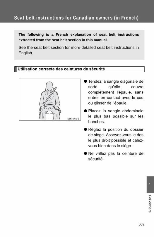
7
For owners
Seat belt instructions for Canadian owners (in French)
The following is a French explanation of seat belt instructionsextracted from the seat belt section in this manual.
See the seat belt section for more detailed seat belt instructions inEnglish.
Utilisation correcte des ceintures de sécurité
● Tendez la sangle diagonale desorte qu'elle couvrecomplètement l'épaule, sansentrer en contact avec le couou glisser de l'épaule.
● Placez la sangle abdominalele plus bas possible sur leshanches.
● Réglez la position du dossierde siège. Asseyez-vous le dosle plus droit possible et calez-vous bien dans le siège.
● Ne vrillez pas la ceinture desécurité.
609

Entretien et soin
■Ceintures de sécurité
Nettoyez avec un chiffon ou une éponge humectée d'eau savonneuse tiède.Profitez de l'occasion pour vérifier régulièrement que les ceintures ne sontpas effilochées, entaillées, ou ne paraissent pas exagérément usées.
ATTENTION
■Détérioration et usure des ceintures de sécurité
Inspectez les ceintures de sécurité périodiquement. Contrôlez qu'elles nesont pas entaillées, effilochées, et que leurs ancrages ne sont pasdesserrés. N'utilisez pas une ceinture de sécurité défectueuse avant qu'ellene soit remplacée. Une ceinture de sécurité défectueuse n'apporte aucunegarantie de protection de l'occupant en cas d'accident.
610

7
For owners
SRS airbag instructions for Canadian owners (in French)
The following is a French explanation of SRS airbag instructions
extracted from the SRS airbag section in this manual.
See the SRS airbag section for more detailed SRS airbag instruc-
tions in English.
Sacs de sécurité gonflables frontaux
Sac de sécurité gonflable conducteur/sac de sécurité gonflablepassager avantParticipent à la protection de la tête et du thorax du conducteuret du passager contre les chocs avec les éléments del'habitacle.
Sac de sécurité gonflable de genoux conducteurContribue à accroître la protection du conducteur.
611

Sacs de sécurité gonflables latéraux et rideau
Sacs de sécurité gonflables latérauxParticipent à la protection du thorax des occupants des siègesavant.
Sacs de sécurité gonflables rideau Participent principalement à la protection de la tête desoccupants assis dans les sièges des places extérieures.
612

7
For owners
Composition du système de sacs de sécurité gonflables
Sacs de sécurité gonflablesrideau
Sacs de sécurité gonflableslatéraux
Sac de sécurité gonflablepassager avant
Capteurs de sacs desécurité gonflables latérauxet rideau
Capteurs de porte
Capteurs de sacs desécurité gonflables frontaux
Contacteur de boucle deceinture de sécuritépassager avant
Capteurs de sacs desécurité gonflables rideau
Témoins indicateurs “AIRBAG ON” et “AIR BAGOFF”
Témoin d'alerte SRS
Sac de sécurité gonflableconducteur
Capteur de la position dusiège conducteur
Contacteur de boucle deceinture de sécuritéconducteur
Sac de sécurité gonflablegenoux conducteur
Boîtier électronique de sacsde sécurité gonflables
Système de classificationde l'occupant du siègepassager avant (ECU etcapteurs)
613

Votre véhicule est équipé de SACS DE SÉCURITÉ GONFLABLESINTELLIGENTS (ADVANCED AIRBAGS) conçus selon les normesde sécurité américaines applicables aux véhicules à moteur(FMVSS208). Le système de sacs de sécurité gonflables régule lapuissance de déploiement des sacs de sécurité gonflablesconducteur et passager avant. Le système de sac de sécuritégonflable conducteur se compose d'un capteur de position de siègeconducteur, etc. Le système de sac de sécurité gonflable passageravant se compose d'un capteur de classification des occupants dusiège passager avant, etc..
Les principaux éléments du système de sacs de sécurité gonflablesSRS sont illustrés ci-dessus. Le système des sacs de sécuritégonflables SRS est commandé par un boîtier électronique. Ce boîtierintègre un capteur de sécurité et un capteur de sac de sécuritégonflable.
Lorsque la violence du choc frontal ou latéral ou du retournement duvéhicule l'exige, le système de sacs de sécurité gonflables SRSdéclenche les dispositifs de gonflage. Le déploiement rapide desairbags est obtenu au moyen d'une réaction chimique dans lesdispositifs de gonflage, qui produit un gaz inoffensif permettantd'amortir le mouvement des occupants.
614

7
For owners
ATTENTION
■Précautions avec les sacs de sécurité gonflables SRS
Respectez les précautions suivantes avec les sacs de sécurité gonflables. À défaut, des blessures graves, voire mortelles, pourraient s'ensuivre.
●Le conducteur et tous les passagers à bord du véhicule doivent porter leurceinture de sécurité correctement.Les sacs de sécurité gonflables SRS sont des dispositifs de protectioncomplémentaires aux ceintures de sécurité.
●Le sac de sécurité gonflable SRS conducteur se déploie avec uneviolence considérable, qui peut être très dangereuse voire mortelle si leconducteur se trouve très près du sac de sécurité gonflable. L'autoritéfédérale chargée de la sécurité routière aux États-Unis, la NHTSA(National Highway Traffic Safety Administration) conseille:
Sachant que la zone de danger pour le sac de sécurité gonflable conducteurse trouve dans les premiers 2 à 3 in. (50 - 75 mm) de déploiement, vousdisposez d'une marge de sécurité confortable en vous plaçant à 10 in. (250mm) de votre sac de sécurité gonflable conducteur. Cette distance est àmesurer entre le moyeu du volant de direction et le sternum. Si vous êtesactuellement assis à moins de 10 in. (250 mm), vous pouvez changer votreposition de conduite de différentes façons:
• Reculez votre siège le plus possible, tout en continuant à pouvoiratteindre confortablement les pédales.
• Inclinez légèrement le dossier du siège. Bien que les véhicules puissent être différents les uns des autres, laplupart des conducteurs peuvent s'asseoir à une distance de 10 in.(250 mm), même avec le siège conducteur complètement avancé,simplement en inclinant un peu le dossier de siège. Si vous avez desdifficultés à voir la route après avoir incliné votre siège, utilisez uncoussin ferme et antidérapant pour vous rehausser ou, si votrevéhicule est équipé du réglage en hauteur du siège, remontez-le.
• Si votre volant de direction est réglable, inclinez-le vers le bas. Cela apour effet d'orienter le sac de sécurité gonflable en direction de votrepoitrine plutôt que de votre tête et de votre cou.
Réglez votre siège selon ces recommandations de la NHTSA, tout enconservant le contrôle des pédales, du volant de direction et la vue descommandes du tableau de bord.
615

ATTENTION
■Précautions avec les sacs de sécurité gonflables SRS
●Le sac de sécurité gonflable SRS passager avant se déploie égalementavec une violence considérable, qui peut être très dangereuse voiremortelle si le passager avant se trouve très près du sac de sécuritégonflable. Éloignez le siège passager avant au maximum du sac desécurité gonflable, et réglez le dossier de siège de sorte à être assis biendroit dans le siège.
●Les nourrissons et les enfants qui ne sont pas correctement assis et/ouprotégés peuvent être grièvement blessés ou tués par le déploiement d'unsac de sécurité gonflable. Installez dans un siège de sécurité enfant lesenfants trop jeunes pour pouvoir utiliser la ceinture de sécurité. Toyotarecommande vivement que les nourrissons et les jeunes enfants soientinstallés sur le siège arrière du véhicule et convenablement attachés.C'est à l'arrière que les nourrissons et les enfants sont les mieux protégés.
●N'installez jamais un siège de sécurité enfant type dos à la route sur lesiège passager avant, même si le témoin “AIR BAG OFF” est allumé. En cas d'accident, par la violence et la vitesse de son déploiement, le sacde sécurité gonflable passager avant peut blesser grièvement, voire tuerl'enfant si vous l'avez installé à la place du passager avant dans un siègede sécurité enfant type dos à la route.
●Si vous attachez une rallonge deceinture de sécurité aux boucles deceinture de sécurité avant, mais pas aupêne de la ceinture de sécurité, lesairbags SRS frontaux détectent que leconducteur et le passager avant ontattaché leur ceinture de sécurité, alorsmême que ce n'est pas le cas. Dans cecas, il se peut que les airbags SRSfrontaux ne se déploient pascorrectement en cas d'accident, et vousrisquez d'être tué ou grièvementblessé. Veillez à porter la ceinture desécurité avec la rallonge de ceinture desécurité.
616
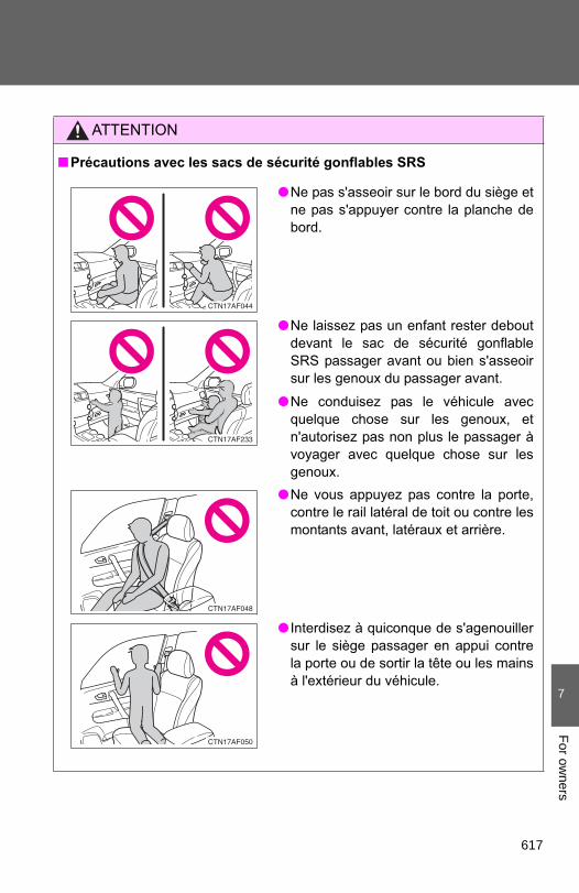
7
For owners
ATTENTION
■Précautions avec les sacs de sécurité gonflables SRS
●Ne pas s'asseoir sur le bord du siège etne pas s'appuyer contre la planche debord.
●Ne laissez pas un enfant rester deboutdevant le sac de sécurité gonflableSRS passager avant ou bien s'asseoirsur les genoux du passager avant.
●Ne conduisez pas le véhicule avecquelque chose sur les genoux, etn'autorisez pas non plus le passager àvoyager avec quelque chose sur lesgenoux.
●Ne vous appuyez pas contre la porte,contre le rail latéral de toit ou contre lesmontants avant, latéraux et arrière.
● Interdisez à quiconque de s'agenouillersur le siège passager en appui contrela porte ou de sortir la tête ou les mainsà l'extérieur du véhicule.
617

ATTENTION
■Précautions avec les sacs de sécurité gonflables SRS
●Si le cache en vinyle recouvre la partie où le sac de sécurité gonflableSRS de genoux se déploie, veillez à l'enlever.
●N'utilisez aucun accessoire de siège venant recouvrir les zones dedéploiement des sacs de sécurité gonflables SRS latéraux, car il risqueraitd'en gêner le déploiement.
●Ne rien fixer ou disposer sur le tableaude bord, la garniture centrale du moyeude volant de direction ou la partieinférieure de la planche de bord. Au déploiement des sacs de sécuritégonflables SRS conducteur, passageravant et genoux, tout objet risque de setransformer en projectile.
●Ne fixez aucun objet sur les portes, lavitre de pare-brise, les vitres latérales,les montants avant et arrière, le raillatéral de toit et la poignée de maintien.
●Ne suspendez aux crochets àvêtements aucun cintre nu ni aucunobjet dur. En cas de déploiement dusac de sécurité gonflable SRS rideau,ces objets peuvent se transformer enprojectiles capables de vous blessergrièvement, voire de vous tuer.
●Véhicules sans système d'accès et dedémarrage “mains libres”: Évitezd'attacher au porte-clés de la clé desobjets lourds, pointus ou très durs. Cesobjets risquent d'entraver ledéploiement du sac de sécuritégonflable SRS de genoux ou d'êtreprojetés vers le siège conducteur par laforce de déploiement, constituant ainsiun danger potentiel.
618

7
For owners
ATTENTION
■Précautions avec les sacs de sécurité gonflables SRS
●Évitez de faire subir des chocs ou des pressions excessives aux zonesrenfermant les composants des sacs de sécurité gonflables SRS ( P. 613).En effet, cela pourrait entraîner un fonctionnement anormal des sacs desécurité gonflables SRS.
●Ne touchez aucun composant du système immédiatement après ledéclenchement (déploiement) des sacs de sécurité gonflables SRS, car ilssont alors encore très chauds.
●Si vous avez des difficultés à respirer après le déploiement d'un sac desécurité gonflable SRS, ouvrez une porte ou une vitre pour faire entrer del'air frais, ou bien descendez du véhicule si cela ne présente pas dedanger. Essuyez tout résidu dès que possible afin d'éviter d'éventuellesirritations de la peau.
●Si les parties renfermant les sacs de sécurité gonflables SRS, telles que lagarniture du moyeu de volant et les garnitures de montants avant etarrière, apparaissent abîmées ou craquelées, faites-les remplacer parvotre concessionnaire Toyota.
619

ATTENTION
■Modification et mise au rebut des éléments du système de sacs de
sécurité gonflables SRS
Consultez impérativement votre concessionnaire Toyota si vous avez besoind'intervenir sur votre véhicule ou de procéder à l'une des modificationssuivantes. Les sacs de sécurité gonflables SRS risquent de ne pas fonctionnercorrectement ou de se déployer (gonfler) accidentellement, provoquant ainsides blessures graves, voire mortelles.
● Installation, dépose, démontage et réparations des sacs de sécuritégonflables SRS.
●Réparation, modification, dépose ou remplacement du volant, du combinéd'instruments, du tableau de bord, des sièges ou de leur sellerie, desmontants avant, latéraux et arrière ou des rails latéraux de toit.
●Réparations ou modifications de l'aile avant, du bouclier avant, ou du côtéde l'habitacle.
● Installation de chasse-neige, de treuils, etc. sur la calandre (pare-buffle,pare-kangourou, etc.).
●Modifications des suspensions du véhicule.
● Installation d'appareils électroniques tels que radio émetteur/récepteur oulecteurs CD.
●Aménagements apportés au véhicule pour une personne atteinte d'unhandicap physique.
620

624
Alphabetical index
Alphabetical index
A/C.....................268, 275, 283, 286ABS ...........................................223Active head restraints ...............75Air conditioning filter...............493Air conditioning system
Air conditioning filter..............493Front automatic air
conditioning system ............275 Front manual air
conditioning system ............268Rear automatic air
conditioning system ............286 Rear manual air
conditioning system ............283Airbags
Airbag operating conditions............................126
Airbag precautions for your child ....................................130
Airbag warning light...............529Curtain shield airbag
operating conditions............126Curtain shield airbag
precautions .........................130Front passenger occupant
classification system...........135General airbag
precautions .........................130Locations of airbags..............123Modification and disposal
of airbags............................134Proper driving
posture........................121, 130Side airbag operating
conditions............................126Side airbag precautions ........130SRS airbags ..........................123
Alarm.........................................116Antenna ............................301, 344Anti-lock brake system ...........223Armrest .....................................422Audio input...............................339Audio system
Antenna.........................301, 344Audio input ............................339AUX port ...............................339CD player/changer ................304iPod.......................................320MP3/WMA disc .....................312Optimal use...........................335Portable music player ...........339Radio.....................................297Steering wheel audio
switch..................................341Type ......................................293USB memory.........................327
Automatic light control system....................................200
Automatic transmission..........177AUX port ...................................339Auxiliary box ........................... 408
A

625
Alphabetical index
Back-up lightsReplacing light bulbs ............ 510Wattage................................ 586
Back doorBack door ............................... 60Smart key system................... 35Wireless remote control.......... 48
BatteryChecking .............................. 473If the vehicle has a
discharged battery ............. 560Preparing and checking
before winter ...................... 243Bluetooth® audio..................... 367Bluetooth® phone ................... 363Bottle holder ............................ 407Brake assist ............................. 223Brakes
Fluid...................................... 472Parking brake ....................... 183
Break-in tips ............................ 161Brightness control
Instrument panel light control ................................ 186
CareExterior..................................440Interior ...................................443Seat belts ..............................444
Cargo capacity .........................242Cargo hooks.............................424CD changer...............................304CD player ..................................304Chains.......................................243Child restraint system
Booster seats, definition........142Booster seats, installation .....147Convertible seats,
definition .............................142Convertible seats,
installation...........................147Front passenger occupant
classification system...........135Infant seats, definition ...........142Infant seats, installation.........147Installing CRS with a top
tether straps........................154Installing CRS with LATCH
anchors ...............................149Installing CRS with seat
belts ....................................151Child safety
Airbag precautions ................130Battery precautions .......475, 563Child restraint system............142Child-protectors.......................56How your child should wear
the seat belt ..........................91Installing child restraints........147Moon roof precautions ..........107Power window lock switch.....101Power window precautions ...103Removed key battery
precautions .........................498Seat belt extender
precautions ...........................93Seat belt precautions ..............91Seat heater precautions ........421
B C

626
Alphabetical index
Child-protectors .........................56Cleaning
Exterior..................................440Interior ...................................443Seat belts ..............................444
Clock .................................191, 414Compass...................................435Condenser ................................471Console box .............................401Conversation mirror ................415Cooling system
Engine overheating ...............564Cruise control...........................215Cup holders..............................403Curtain shield airbags .............123Customizable features.............602
Daytime running light system....................................204
DefoggerRear window .........................289Side mirrors...........................289
Dimension ................................572Dinghy towing..........................265Display
Trip information .....................191Warning message .................539
Do-it-yourself maintenance ....453Door courtesy lights
Door courtesy lights ..............396Wattage.................................586
DoorsDoor lock.....................35, 48, 54Door windows .......................101Side mirrors.............................98
Downhill assist control system....................................230
Driver's seat belt reminder light.........................................531
DrivingBreak-in tips ..........................161Correct posture .....................121Procedures............................160Winter driving tips .................243
D

627
Alphabetical index
Electric power steering........... 223Electronic key
If your electronic key battery is discharged.......... 558
Emergency flashersSwitch................................... 518
Emergency, in case ofIf a warning message is
displayed............................ 539If the back door opener is
inoperative ........................... 63If the electronic key does
not operate properly........... 558If the engine will not start...... 554If the shift lever cannot be
shifted from P..................... 556If the vehicle has a
discharged battery ............. 560If the warning buzzer
sounds... ........................... 528If the warning light turns
on....................................... 528If you have a flat tire ............ 540If you lose your keys/
wireless remote control transmitter .......................... 557
If you think something is wrong ................................. 526
If your vehicle becomes stuck................................... 567
If your vehicle has to be stopped in an emergency ......................... 569
If your vehicle needs to be towed ................................. 519
If your vehicle overheats ...... 564
EngineCompartment ........................463Engine switch ................170, 174Hood......................................457How to start the
engine .........................170, 174Identification number.............573If the engine will not start ......554Ignition switch................170, 174Overheating...........................564
Engine compartment cover.....465Engine coolant
Capacity ................................580Checking ...............................469Preparing and checking
before winter .......................243Engine coolant temperature
gauge......................................185Engine immobilizer system.....113Engine oil
Capacity ................................576Checking ...............................466Preparing and checking
before winter .......................243Enhanced vehicle stability
control ....................................223Enhanced VSC .........................223EPS............................................223Event data recorder ...................26
E

628
Alphabetical index
Floor mat...................................423Fluid
Brake.....................................472Washer..................................477
Fog lightsReplacing light bulbs .............510Switch....................................206Wattage.................................586
Front automatic air conditioning system..............275
Front fog lightsReplacing light bulbs .............510Switch....................................206Wattage.................................586
Front manual air conditioning system..............268
Front passenger occupant classification system ............135
Front passenger's seat belt reminder light.........................531
Front seatsAdjustment ..............................74
Front side marker lightsReplacing light bulbs .............510Switch....................................200Wattage.................................586
Front turn signal lightsReplacing light bulbs .............510Wattage.................................586
FuelCapacity ................................575Fuel gauge ............................185Fuel pump shut off system....527Gas station information .........636Information ............................587Refueling ...............................109Type ......................................575
Fuel door...................................109Fuel filler door ..........................109Fuel pump shut off system .....527Fuses.........................................499
Garage door opener ................429Gas station information ..........636Gauges......................................185Glove box .................................400Grocery bag hooks ..................424
Hands-free system (for cellular phone)................363
Hazard lights switch ................518Head restraints
Active head restraints .............75Adjusting ................................85
HeadlightsReplacing light bulbs.............510Switch ...................................200Wattage.................................586
HeatersSeat heaters..........................420Side mirror ............................289
Hood..........................................457Hooks
Cargo hook ...........................424Shopping bag........................424
Horn ..........................................184
I/M test ......................................452Identification
Engine...................................573Vehicle ..................................573
Ignition switch..................170, 174Illuminated entry system.........396Indicator lights .........................187Initialization
Items to initialize ...................606Inside rear view mirror ..............95Instrument panel light
control ....................................186Interior lights
Interior lights .........................396Switch ...........................397, 398Wattage.................................586
F G
H
I

629
Alphabetical index
JackPositioning a floor jack ......... 459Vehicle-equipped jack .......... 540
Jack handle.............................. 540
Keyless entry............................. 48Keys
Electronic key ......................... 32Engine switch ............... 170, 174If the electronic key does
not operate properly........... 558If you lose your keys/
wireless remote control transmitter .......................... 557
Ignition switch............... 170, 174Key number ............................ 32Keyless entry.......................... 48Keys ....................................... 32Mechanical key....................... 32Wireless remote control
key ....................................... 48
License plate lightsReplacing light bulbs ............ 510Wattage................................ 586
Light bulbsReplacing ............................. 510Wattage................................ 586
LightsDoor courtesy lights.............. 396Emergency flasher switch .... 518Fog light switch..................... 206Hazard light switch ............... 518Headlight switch ................... 200Interior light switch........ 397, 398Outer foot lights .................... 396Personal light switch............. 397Replacing light bulbs ............ 510Turn signal lever................... 182Vanity lights .......................... 413Wattage................................ 586
Load capacity .......................... 242
Lock steering column......172, 175Luggage cover .........................425
MaintenanceDo-it-yourself
maintenance .......................453General maintenance............449Maintenance data..................572Maintenance requirements....446
Maintenance data.....................447Meter
Instrument panel light control .................................186
Meters ...................................185Mirrors
Conversation mirror...............415Inside rear view mirror.............95Side mirror heaters................289Side mirrors.............................98Vanity mirrors ........................413
Moon roof .................................104MP3 disc ...................................312Multi-information
display ....................................191
Noise from under vehicle ..........24
Odometer ..................................185Off-road precautions ...............233Oil
Engine oil ..............................466Opener
Back door ................................60Fuel filler door .......................109Glass hatch .............................70Hood......................................457
Outside rear view mirrorsAdjusting and folding...............98
Outside temperature display ....................................191
Overhead console....................402Overheating, Engine ................564
J
K
L
M
N
O

630
Alphabetical index
Parking brake ...........................183Parking lights
Replacing light bulbs .............510Switch....................................200Wattage.................................586
Personal/interior lightsSwitch....................................397Wattage.................................586
Power outlet .............................416Power windows........................101
Radiator ....................................471Radio.........................................297Rear automatic air
conditioning system..............286Rear manual air conditioning
system ....................................283Rear seat
Adjustment ..............................77Folding down second
seatback ...............................78Folding down third
seatback ...............................80Removing the second
center seat ............................81Stowing the second
center seat ............................81Rear seat entertainment
system*Rear turn signal lights
Replacing light bulbs .............510Wattage.................................586
Rear view mirrorCompass...............................435
Rear view monitor system ......219Rear window defogger ............289Rear window wiper ..................212
Replacing Fuses ....................................499Key battery............................496Light bulbs.............................510Tires ......................................540
Reporting safety defects for U.S. owners............................608
Roof luggage carrier................241
Seat beltsAdjusting the seat belt.............88Automatic Locking
Retractor...............................89Child restraint system
installation...........................147Cleaning and maintaining
the seat belts ......................444Emergency Locking
Retractor...............................89How to wear your seat belt .....88How your child should wear
the seat belt ..........................91Pregnant women,
proper seat belt use..............90Reminder light.......................531Seat belt extenders .................91Seat belt pretensioners ...........89
Seat heaters .............................420Seating capacity ......................242Seats
Adjustment ........................74, 77Adjustment precaution ......76, 84Child seats/child restraint
system installation ..............147Cleaning................................443Head restraint .........................85Properly sitting in the seat.....121Seat heaters..........................420
P
R
S

631
Alphabetical index
Service reminder indicators .............................. 187
Shift leverAutomatic transmission ........ 177If the shift lever cannot
be shifted from P................ 556Shift lock system..................... 556Shopping bag hooks............... 424Side airbags............................. 123Side marker lights
Replacing ............................. 510Switch................................... 200Wattage................................ 586
Side mirrorsAdjusting and folding .............. 98
Side table ................................. 410Smart key system
Entry function ......................... 35Starting the engine ............... 170
Spare tireInflation pressure.................. 584Storage location ................... 540
Spark plug................................ 581Specifications.......................... 572Speech command switch ....... 368Speedometer ........................... 185Steering
Column lock release..... 172, 175Steering wheel
Adjustment ............................. 94Audio switches ..................... 341Climate remote control
switches ............................. 292Stop lights
Replacing light bulbs ............ 510Wattage................................ 586
Storage feature........................ 399Storage precautions ............... 240Stuck
If your vehicle becomes stuck................................... 567
Sun visors.................................412Switch
Emergency flasher switch .....518Engine switch ................170, 174Fog light switch .....................206Hazard light switch ................518Ignition switch................170, 174Light switches........................200Power door lock switch ...........55Power window switch ............101SNOW switch ........................178Window lock switch ...............101Wiper and washer
switch..........................208, 212
Tachometer...............................185Tail lights
Replacing light bulbs .............510Switch....................................200Wattage.................................586
Talk switch................................368Telephone switch.....................368Theft deterrent system
Alarm.....................................116Engine immobilizer system ...113
Theft prevention labels............120Tire inflation pressure .............487Tire information
Glossary ................................596Size .......................................593Tire identification number......592Uniform tire quality
grading................................594
T
*: Refer to the “Navigation System Owner’s Manual”

632
Alphabetical index
TiresChains ...................................243Checking ...............................478If you have a flat tire..............540Inflation pressure...................487Information ............................590Replacing ..............................540Rotating tires .........................478Size .......................................584Snow tires .............................243Tire pressure warning
system ........................478, 531Tools .........................................540Total load capacity...................242Towing
Dinghy towing........................265Emergency towing.................520Trailer towing.........................247
Traction control........................223TRAC.........................................223Trip information .......................191Trip meter .................................185Turn signal lights
Replacing light bulbs .............510Switch....................................182Wattage.................................586
Valet key .....................................32Vanity lights
Vanity lights...........................413Wattage.................................586
Vanity mirrors...........................413Vehicle identification
number ...................................573Vehicle stability control...........223VSC............................................223
Warning buzzersBrake system ........................528Open door .............................531Seat belt reminder.................531
Warning lightsAnti-lock brake system..........529Brake assist system..............529Brake system ........................528Charging system...................529Electric power steering
system ................................529Electronic engine control
system ................................529Engine oil pressure ...............529Malfunction indicator lamp ....529Master warning light..............531Open door .............................531Pretensioners........................529Seat belt reminder light .........531SRS airbags..........................529Tire pressure warning light....531
Warning messages ..................539Washer
Checking ...............................477Preparing and checking
before winter.......................243Switch ...........................208, 212
Washing and waxing ...............440Weight
Cargo capacity ......................238Load limits.............................242Weight...................................572
Wheels ......................................490Window glasses ......................101Window lock switch.................101Windows
Power windows.....................101Rear window defogger ..........289Washer..........................208, 212
Windshield wiper de-icer ........291Windshield wipers ...................208Wireless remote control key
Replacing the battery ............496Wireless remote control key....48
WMA disc..................................312
V
W

What to do if...
What to do if...
A tire punctures P. 540 If you have a flat tire
The engine does not startP. 554 If the engine will not startP. 113 Engine immobilizer systemP. 560 If the battery is discharged
The shift lever cannot be moved out
P. 556If the shift lever cannot be shifted from P
The engine coolant temperature gauge enters the red zone
Steam can be seen coming from under the hood
P. 564 If your vehicle overheats
The key is lost P. 557If you lose your keys/wireless remote control transmitter
The battery runs out P. 560 If the battery is discharged
The doors cannot be lockedP. 54 Side doorsP. 60 Back door
The horn begins to sound P. 116 Alarm
The vehicle is stuck in mud or sand
P. 567 If the vehicle becomes stuck
633

What to do if...
A warning light or indicator light comes on
P. 528If a warning light turns on or a warning buzzer sounds...
■Warning lights
P. 531or
P. 528 P. 531
P. 529or
P. 529 P. 531
P. 531or
P. 529 P. 531
P. 529 P. 531
P. 531
Brake system warning light
Low fuel level warning light
Driver’s seat belt reminder light
Charging system warn-ing light
Front passenger’s seat belt reminder light
Low engine oil pressure warning light
Malfunction indicator lamp
Master warning light
Maintenance Required reminder light
SRS warning light Low washer fluid warn-ing light
Open door warning light
634

What to do if...
P. 531or
P. 529 P. 531
P. 529 P. 529
P. 529
*: The light flashes to indicate a malfunction.
ABS warning light Automatic transmission fluid temper-ature warning light
Tire pressure warning light
Electric power steering warning light
Cruise control indicator light*
Slip indicator light
A warning message is displayed
P. 539 If a warning message is displayed
635

636
GAS STATION INFORMATION
Auxiliary catch leverP. 457
Fuel filler doorP. 109
Back door openerP. 60
Hood release leverP. 457
Fuel filler door openerP. 109
Tire inflation pressureP. 584
Fuel tank capacity (Reference) 19.2 gal. (72.5 L, 15.9 Imp. gal.)
Fuel type Unleaded gasoline with an Octane Rating of 87 (Research Octane Number 91)
Cold tire inflation pressure P. 584
Engine oil capacity(Drain and refill ⎯ reference) P. 576
Engine oil type
Toyota Genuine Motor Oil or equivalentOil grade: P. 576
ILSAC multigrade engine oilRecommended oil viscosity:
2.7 L 4-cylinder (1AR-FE) engine5W-20 and 0W-203.5 L V6 (2GR-FE) engine0W-20