2012 Ram Truck Diesel Supplement - Vehicles for Business · A MESSAGE FROM CHRYSLER GROUP LLC...
173
Ram Truck OWNER’S MANUAL 2012 Diesel Supplement
Transcript of 2012 Ram Truck Diesel Supplement - Vehicles for Business · A MESSAGE FROM CHRYSLER GROUP LLC...
877615cv1.psp 12D241-226-AB Chrysler 1" gutter 06/07/2011 08:12:07
Chrysler Group LLC12D241-226-AB Second Edition Printed in U.S.A.
20
12
RA
M T
RU
CK
DIE
SE
L R a m T r u c k O W N E R ’ S M A N U A L
2 0 1 2D i e s e l S u p p l e m e n t
R a m T r u c k O W N E R ’ S M A N U A L
2 0 1 2D i e s e l S u p p l e m e n t
Chrysler Group LLC12D241-226-AB Second Edition Printed in U.S.A.
20
12
RA
M T
RU
CK
DIE
SE
L
877615cv1.psp 12D241-226-AB Chrysler 1" gutter 06/07/2011 08:12:07
VEHICLES SOLD IN CANADAWith respect to any Vehicles Sold in Canada, the nameChrysler Group LLC shall be deemed to be deleted and thename Chrysler Canada Inc. used in substitution therefore.
DRIVING AND ALCOHOLDrunken driving is one of the most frequent causes of acci-dents.
Your driving ability can be seriously impaired with blood alcohollevels far below the legal minimum. If you are drinking, don’tdrive. Ride with a designated non-drinking driver, call a cab, afriend, or use public transportation.
WARNING!
Driving after drinking can lead to an accident. Your per-ceptions are less sharp, your reflexes are slower, and yourjudgment is impaired when you have been drinking.Never drink and then drive.
This manual illustrates and describes the operation of featuresand equipment that are either standard or optional on thisvehicle. This manual may also include a description of featuresand equipment that are no longer available or were not orderedon this vehicle. Please disregard any features and equipmentdescribed in this manual that are not on this vehicle.
Chrysler Group LLC reserves the right to make changes indesign and specifications, and/or make additions to or im-provements to its products without imposing any obligationupon itself to install them on products previously manufac-tured.
Copyright © 2011 Chrysler Group LLC
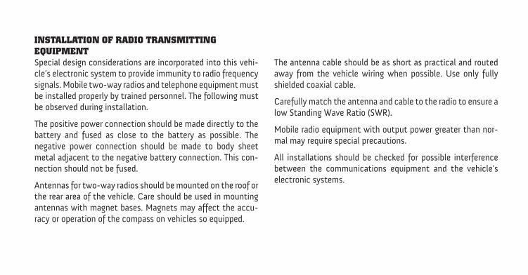
INSTALLATION OF RADIO TRANSMITTINGEQUIPMENTSpecial design considerations are incorporated into this vehi-cle’s electronic system to provide immunity to radio frequencysignals. Mobile two-way radios and telephone equipment mustbe installed properly by trained personnel. The following mustbe observed during installation.
The positive power connection should be made directly to thebattery and fused as close to the battery as possible. Thenegative power connection should be made to body sheetmetal adjacent to the negative battery connection. This con-nection should not be fused.
Antennas for two-way radios should be mounted on the roof orthe rear area of the vehicle. Care should be used in mountingantennas with magnet bases. Magnets may affect the accu-racy or operation of the compass on vehicles so equipped.
The antenna cable should be as short as practical and routedaway from the vehicle wiring when possible. Use only fullyshielded coaxial cable.
Carefully match the antenna and cable to the radio to ensure alow Standing Wave Ratio (SWR).
Mobile radio equipment with output power greater than nor-mal may require special precautions.
All installations should be checked for possible interferencebetween the communications equipment and the vehicle’selectronic systems.
TABLE OF CONTENTSSECTION PAGE
1 INTRODUCTION . . . . . . . . . . . . . . . . . . . . . . . . . . . . . . . . . . . . . . . . . . . . . . . . . . . . . . . . . . . . 3
2 THINGS TO KNOW BEFORE STARTING YOUR VEHICLE . . . . . . . . . . . . . . . . . . . . . . . . . . . . . .7
3 UNDERSTANDING YOUR INSTRUMENT PANEL . . . . . . . . . . . . . . . . . . . . . . . . . . . . . . . . . . . 13
4 STARTING AND OPERATING . . . . . . . . . . . . . . . . . . . . . . . . . . . . . . . . . . . . . . . . . . . . . . . . . 31
5 WHAT TO DO IN EMERGENCIES . . . . . . . . . . . . . . . . . . . . . . . . . . . . . . . . . . . . . . . . . . . . . . 91
6 MAINTAINING YOUR VEHICLE . . . . . . . . . . . . . . . . . . . . . . . . . . . . . . . . . . . . . . . . . . . . . . . 97
7 MAINTENANCE SCHEDULES . . . . . . . . . . . . . . . . . . . . . . . . . . . . . . . . . . . . . . . . . . . . . . . . . 137
8 INDEX . . . . . . . . . . . . . . . . . . . . . . . . . . . . . . . . . . . . . . . . . . . . . . . . . . . . . . . . . . . . . . . . . . . 163
1
2
3
4
5
6
7
8

INTRODUCTION
CONTENTS
� A Message From Chrysler Group LLC . . . . . . . . . 4
1
A MESSAGE FROM CHRYSLER GROUP LLCChrysler Group LLC and Cummins� welcome you as aCummins� turbocharged diesel-powered truck owner.Your diesel truck will sound, feel, drive, and operatedifferently from a gasoline-powered truck. It is importantthat you read and understand this manual.
Almost 100% of the heavy duty trucks in the UnitedStates and Canada are diesel-powered because of the fueleconomy, rugged durability, and high torque which per-mits pulling heavy loads. Cummins� engines power wellover half of these trucks. Now this same technology andproven performance is yours in your truck equippedwith the Cummins� turbocharged diesel engine.
You may find that some of the starting, operating, andmaintenance procedures are different. However, they aresimple to follow and careful adherence to them willensure that you take full advantage of the features of thisengine.
NOTE: Some aftermarket products may cause severeengine/transmission and/or exhaust system damage.Your vehicle’s Powertrain Control Systems can detectand store information about vehicle modifications thatincrease horsepower and torque output such as whetheror not performance-enhancing powertrain components,commonly referred to as downloaders, power boxes, orperformance chips have been used.
This information cannot be erased and will stay in thesystem’s memory even if the modification is removed.This information can be retrieved by Chrysler GroupLLC, and service and repair facilities, when servicingyour vehicle. This information may be used to determineif repair will be covered by New Vehicle Limited War-ranty.
4 INTRODUCTION
There is a probability that the use of a “performancechip” will prohibit the engine from starting. In thisinstance, the vehicle will need to be serviced by aauthorized dealer in order to return the vehicle to it’sfactory settings.
1
INTRODUCTION 5

THINGS TO KNOW BEFORE STARTING YOUR VEHICLE
CONTENTS
� Steering Wheel Lock — If Equipped . . . . . . . . . . 8
▫ To Manually Lock The Steering Wheel . . . . . . . 8
▫ To Release The Steering Wheel Lock . . . . . . . . . 8
� Remote Starting System — If Equipped . . . . . . . . 8
▫ How To Use Remote Start . . . . . . . . . . . . . . . . 9
� Engine Break-In Recommendations . . . . . . . . . . 12
2
STEERING WHEEL LOCK — IF EQUIPPEDYour vehicle may be equipped with a passive steeringwheel lock. This lock prevents steering the vehicle with-out the key fob. If the steering wheel is moved approxi-mately a half turn in either direction and the key fob isnot in the ignition switch, the steering wheel will lock.
To Manually Lock The Steering WheelWith the engine running, turn the steering wheel upsidedown, turn off the engine and remove the key fob. Turnthe steering wheel slightly in either direction until thelock engages.
To Release The Steering Wheel LockInsert the key fob into the ignition switch and start theengine. If the key fob is difficult to turn, move the wheelslightly to the right or left to disengage the lock.
NOTE: If you turned the wheel to the right to engagethe lock, you must turn the wheel slightly to the right to
disengage it. If you turned the wheel to the left to engagethe lock, turn the wheel slightly to the left to disengage it.
REMOTE STARTING SYSTEM — IF EQUIPPEDThis system uses the Remote Keyless Entry(RKE) transmitter to start the engine conve-niently from outside the vehicle while stillmaintaining security. The system has a range of
approximately 328 ft (100 m).
NOTE:• The vehicle must be equipped with an automatic
transmission to be equipped with Remote Start.
• The remote start system will wait for the “Wait To StartLight” to extinguish before cranking the engine. Thisallows time for the intake heater to pre-heat theincoming air, and is normal operation in cold weather.Refer to “Electronic Vehicle Information Center/EVIC
8 THINGS TO KNOW BEFORE STARTING YOUR VEHICLE
Warning Lights” in “Understanding Your InstrumentPanel” for further information on and “Wait To StartLight” and pre-heat cycle.
How To Use Remote StartAll of the following conditions must be met before theengine will remote start:
• Shift lever in PARK
• Doors closed
• Hood closed
• HAZARD switch off
• BRAKE switch inactive (brake pedal not pressed)
• Ignition key removed from ignition switch
• Battery at an acceptable charge level
• RKE PANIC button not pressed
• Fuel meets minimum requirement
• Water In Fuel Indicator Light is not illuminated
• Wait To Start Light is not illuminated
WARNING!
• Do not start or run an engine in a closed garage orconfined area. Exhaust gas contains Carbon Mon-oxide (CO) which is odorless and colorless. Car-bon Monoxide is poisonous and can cause seriousinjury or death when inhaled.
• Keep Remote Keyless Entry (RKE) transmittersaway from children. Operation of the Remote StartSystem, windows, door locks or other controlscould cause serious injury or death.
2
THINGS TO KNOW BEFORE STARTING YOUR VEHICLE 9
Remote Start Abort Message On Electronic VehicleInformation Center (EVIC) – If EquippedThe following messages will display in the EVIC if thevehicle fails to remote start or exits remote start prema-turely:
• Remote Start Aborted - Door Ajar
• Remote Start Aborted - Hood Ajar
• Remote Start Aborted - Fuel Low
• Remote Start Aborted - System Fault
The EVIC message stays active until the ignition is turnedto the ON/RUN position.
To Enter Remote Start ModePress and release the REMOTE START buttonon the RKE transmitter twice, within five sec-onds. The parking lights will flash and the horn
will chirp twice (if programmed). In cold ambient tem-perature conditions, the diesel vehicle may delay crankup to 30 seconds for the glow plugs or grid heater. Oncethe vehicle has started, the engine will run for 15 min-utes.
NOTE:• The park lamps will turn on and remain on during
Remote Start mode.
• For security, power window and power sunroof op-eration (if equipped) are disabled when the vehicle isin the Remote Start mode.
• The engine can be started two consecutive times (two15-minute cycles) with the RKE transmitter. However,the ignition switch must be cycled to the ON positionbefore you can repeat the start sequence for a thirdcycle.
10 THINGS TO KNOW BEFORE STARTING YOUR VEHICLE

To Exit Remote Start Mode Without Driving TheVehiclePress and release the REMOTE START button one time orallow the engine to run for the entire 15-minute cycle.
NOTE: To avoid unintentional shut downs, the systemwill disable the one time press of the REMOTE STARTbutton for two seconds after receiving a valid RemoteStart request.
To Exit Remote Start Mode And Drive The VehicleBefore the end of the 15-minute cycle, press and releasethe UNLOCK button on the RKE transmitter to unlockthe doors and disarm the Vehicle Security Alarm System(if equipped). Insert the Key Fob into the ignition switchand turn the switch to the ON/RUN position.
NOTE:• The ignition switch must be in the ON/RUN position
in order to drive the vehicle.
• For vehicles equipped with the Electronic VehicleInformation Center (EVIC), the message “Insert Key/Turn To On” will flash in the EVIC until you insert theKey Fob into the ignition swich. Once inserted, themessage “Turn To On” will flash in the EVIC until youturn the ignition switch to the ON/RUN position.
Remote Start Comfort Systems – If EquippedWhen remote start is activated, the heated steeringwheel, and driver heated seat features will automaticallyturn on in cold weather. In warm weather, the drivervented seat feature will automatically turn on when theremote start is activated. These features will stay onthrough the duration of remote start or until the ignitionswitch is turned to the ON position.
The Remote Start Comfort System can be activated anddeactivated through the Electronic Vehicle InformationCenter (EVIC). For more information on Remote StartComfort System operation refer to “Electronic Vehicle
2
THINGS TO KNOW BEFORE STARTING YOUR VEHICLE 11
Information Center (EVIC)/Customer-ProgrammableFeatures (System Setup)” in “Understanding Your Instru-ment Panel”.
ENGINE BREAK-IN RECOMMENDATIONSThe Cummins� turbocharged diesel engine does notrequire a break-in period due to its construction. Normaloperation is allowed, providing the following recommen-dations are followed:
• Warm up the engine before placing it under load.
• Do not operate the engine at idle for prolongedperiods.
• Use the appropriate transmission gear to preventengine lugging.
• Observe vehicle oil pressure and temperature indica-tors.
• Check the coolant and oil levels frequently.
• Vary throttle position at highway speeds when carry-ing or towing significant weight.
NOTE: Light duty operation such as light trailer towingor no load operation will extend the time before theengine is at full efficiency. Reduced fuel economy andpower may be seen at this time.
For additional vehicle break-in requirements, refer to“Trailer Towing” in “Starting and Operating” of theOwners Manual.
Because of the construction of the Cummins� turbo-charged diesel engine, engine run-in is enhanced byloaded operating conditions which allow the engineparts to achieve final finish and fit during the first6,000 miles (10 000 km).
12 THINGS TO KNOW BEFORE STARTING YOUR VEHICLE
UNDERSTANDING YOUR INSTRUMENT PANEL
CONTENTS
� Instrument Cluster . . . . . . . . . . . . . . . . . . . . . 14
� Instrument Cluster Description . . . . . . . . . . . . . 15
� Electronic Vehicle Information Center (EVIC) . . . 25
▫ EVIC Displays . . . . . . . . . . . . . . . . . . . . . . . 26
▫ Vehicle Information (Customer InformationFeatures) . . . . . . . . . . . . . . . . . . . . . . . . . . . 30
3
INSTRUMENT CLUSTER
14 UNDERSTANDING YOUR INSTRUMENT PANEL
INSTRUMENT CLUSTER DESCRIPTION
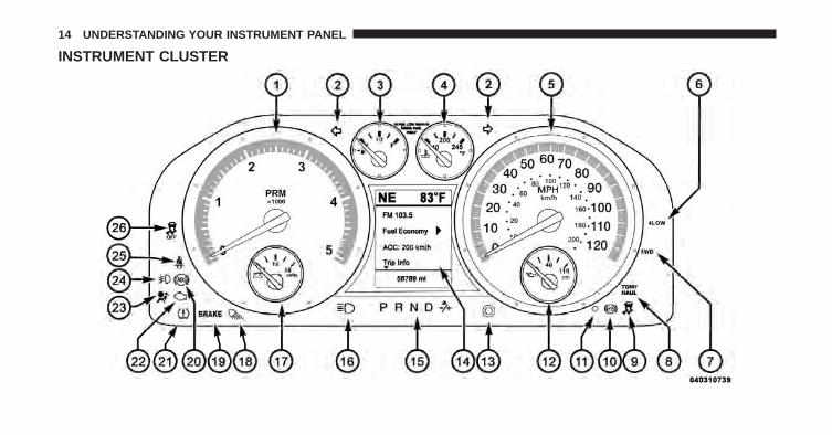
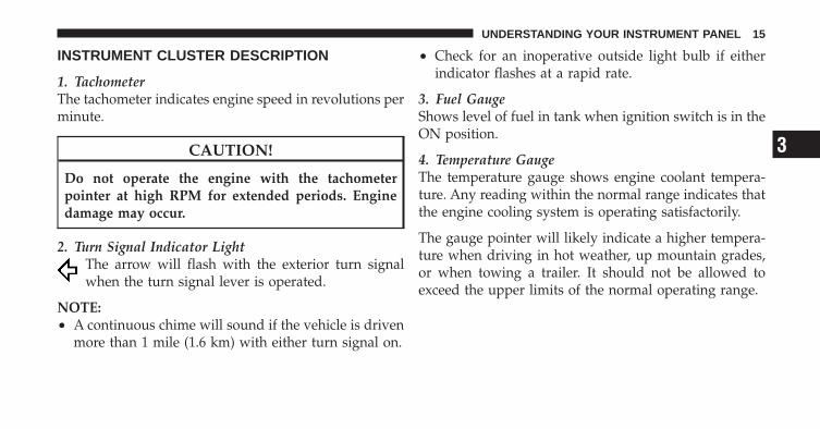
1. TachometerThe tachometer indicates engine speed in revolutions perminute.
CAUTION!
Do not operate the engine with the tachometerpointer at high RPM for extended periods. Enginedamage may occur.
2. Turn Signal Indicator LightThe arrow will flash with the exterior turn signalwhen the turn signal lever is operated.
NOTE:• A continuous chime will sound if the vehicle is driven
more than 1 mile (1.6 km) with either turn signal on.
• Check for an inoperative outside light bulb if eitherindicator flashes at a rapid rate.
3. Fuel GaugeShows level of fuel in tank when ignition switch is in theON position.
4. Temperature GaugeThe temperature gauge shows engine coolant tempera-ture. Any reading within the normal range indicates thatthe engine cooling system is operating satisfactorily.
The gauge pointer will likely indicate a higher tempera-ture when driving in hot weather, up mountain grades,or when towing a trailer. It should not be allowed toexceed the upper limits of the normal operating range.
3
UNDERSTANDING YOUR INSTRUMENT PANEL 15
WARNING!
A hot engine cooling system is dangerous. You orothers could be badly burned by steam or boilingcoolant. You may want to call an authorized dealer-ship for service if your vehicle overheats.
5. SpeedometerThe speedometer shows the vehicle speed in miles perhour and/or kilometers per hour (MPH/km/h).
6. 4LOW Indicator Light – If EquippedThis light alerts the driver that the vehicle is inthe four-wheel drive LOW mode. The front andrear driveshafts are mechanically locked to-gether forcing the front and rear wheels to
rotate at the same speed. Low range provides a greatergear reduction ratio to provide increased torque at thewheels.
For vehicles equipped with a premium cluster this indi-cator will display in the Electronic Vehicle InformationCenter (EVIC). Refer to ”Electronic Vehicle InformationCenter (EVIC)” in “Understanding Your InstrumentPanel” for further information.
7. 4WD Indicator Light – If EquippedThis light indicates the vehicle is in four-wheeldrive and 4LOCK. 4WD allows all four wheelsto receive torque from the engine simultane-ously.
8. TOW/HAUL Indicator Light – If EquippedThe TOW HAUL button is located on thecenter stack switch bank. This light will illumi-nate when TOW HAUL mode is selected
16 UNDERSTANDING YOUR INSTRUMENT PANEL
9. Electronic Stability Control (ESC) IndicatorLight/Traction Control System (TCS) Indicator Light –If Equipped
If the Electronic Stability Control (ESC)/Traction Control System (TCS) Indicator Lightbegins to flash during acceleration, ease up onthe accelerator and apply as little throttle as
possible. This indicator light starts to flash as soon as thetires lose traction and the Electronic Stability Control(ESC) becomes active. The “ESC/TCS Indicator Light”also flashes when TCS is active. Be sure to adapt yourspeed and driving to the prevailing road conditions. Ifthe “ESC/TCS Indicator Light” is on solid, the ESCsystem has been turned off by the driver or a temporarycondition exists that will not allow full ESC function.
10. Exhaust Brake Indicator LightThis light will illuminate when the exhaust brake hasbeen turned on.
11. Vehicle Security Light — If EquippedThis light will flash at a fast rate for approxi-mately 15 seconds, when the vehicle securityalarm is arming, and then will flash slowlyuntil the vehicle is disarmed.
12. Oil Pressure GaugeThe pointer should always indicate some oil pressurewhen the engine is running. A continuous high or lowreading under normal driving conditions may indicate alubrication system malfunction. Immediate serviceshould be obtained from an authorized dealer.
13. Odometer/Trip Odometer ButtonPress this button to toggle between the odometer and thetrip odometer display. Holding the button in resets thetrip odometer reading when in trip mode.
3
UNDERSTANDING YOUR INSTRUMENT PANEL 17
14. Odometer/Electronic Vehicle Information Center(EVIC) Display
OdometerThe odometer shows the total distance the vehicle hasbeen driven. U.S. federal regulations require that upontransfer of vehicle ownership, the seller certify to thepurchaser the correct mileage that the vehicle has beendriven. Therefore, if the odometer reading is changedduring repair or replacement, be sure to keep a record ofthe reading before and after the service so that the correctmileage can be determined.
The two trip odometers show individual trip mileage. Toswitch from odometer to trip odometers, press andrelease the TRIP ODOMETER button.
To reset a trip odometer, display the desired trip odom-eter to be reset then push and hold the button forapproximately two seconds until the display resets.
15. Shift Lever IndicatorThis display indicator shows the transmission shift leverselection.
16. High Beam Indicator LightThis indicator shows that headlights are on highbeam. Push the multifunction lever forward to
switch the headlights to high beam, and pull towardyourself (normal position) to return to low beam.
17. VoltmeterWhen the engine is running, the gauge indicates theelectrical system voltage. The pointer should stay withinthe normal range if the battery is charged. If the pointermoves to either extreme left or right and remains thereduring normal driving, the electrical system should beserviced.
18 UNDERSTANDING YOUR INSTRUMENT PANEL
NOTE: The voltmeter may show a gauge fluctuation atvarious engine temperatures. This cycling operation iscaused by the post-heat cycle of the intake manifoldheater system. The number of cycles and the length of thecycling operation is controlled by the engine controlmodule. Post-heat operation can run for several minutes,and then the electrical system and voltmeter needle willstabilize.
18. Cargo LightThe cargo light will illuminate when the cargolight is activated by pressing the cargo lightbutton on the headlight switch.
19. Brake Warning LightThis light monitors various brake functions,including brake fluid level and parking brakeapplication. If the brake light turns on, it may
indicate that the parking brake is applied, that the brakefluid level is low, or that there is a problem with theAnti-Lock Brake System reservoir.
If the light remains on when the parking brake has beendisengaged, and the fluid level is at the full mark on themaster cylinder reservoir, it indicates a possible brakehydraulic system malfunction or that a problem with theBrake Booster has been detected by the Anti-Lock BrakeSystem (ABS). In this case, the light will remain on untilthe condition has been corrected. If the problem is relatedto the brake booster, the ABS pump will run whenapplying the brake and a brake pedal pulsation may befelt during each stop.
The dual brake system provides a reserve braking capac-ity in the event of a failure to a portion of the hydraulicsystem. A leak in either half of the dual brake system is
3
UNDERSTANDING YOUR INSTRUMENT PANEL 19
indicated by the “Brake Warning Light,” which will turnon when the brake fluid level in the master cylinder hasdropped below a specified level.
The light will remain on until the cause is corrected.
NOTE: The light may flash momentarily during sharpcornering maneuvers, which change fluid level condi-tions. The vehicle should have service performed, andthe brake fluid level checked.
If brake failure is indicated, immediate repair is neces-sary.
WARNING!
Driving a vehicle with the “Brake Warning Light” onis dangerous. Part of the brake system may havefailed. It will take longer to stop the vehicle. Youcould have an accident. Have the vehicle checkedimmediately.
Vehicles equipped with the ABS, are also equipped withElectronic Brake Force Distribution (EBD). In the event ofan EBD failure, the “Brake Warning Light” will turn onalong with the “ABS Warning Light.” Immediate repairto the ABS system is required.
Operation of the “Brake Warning Light” can be checkedby turning the ignition switch from the OFF position tothe ON position. The light should illuminate for approxi-mately two seconds. The light should then turn off unlessthe parking brake is applied or a brake fault is detected.If the light does not illuminate, have the light inspectedby an authorized dealer.
The light also will turn on when the parking brake isapplied with the ignition switch in the ON position.
NOTE: This light shows only that the parking brake isapplied. It does not show the degree of brake application.
20 UNDERSTANDING YOUR INSTRUMENT PANEL
20. Anti-Lock Brake (ABS) Warning LightThis light monitors the Anti-Lock Brake System(ABS). The light will turn on when the ignitionswitch is turned to the ON position and maystay on for as long as four seconds.
If the “ABS Warning Light” remains on or turns on whiledriving, it indicates that the anti-lock portion of the brakesystem is not functioning and that service is required.However, the conventional brake system will continue tooperate normally if the “Brake Warning Light” is not on.
If the “ABS Warning Light” is on, the brake systemshould be serviced as soon as possible to restore thebenefits of anti-lock brakes. If the “ABS Warning Light”does not turn on when the ignition switch is turned to theON position, have the light inspected by an authorizeddealer.
21. Tire Pressure Monitoring Telltale Light – IfEquipped
Each tire, including the spare (if provided),should be checked monthly, when cold andinflated to the inflation pressure recommendedby the vehicle manufacturer on the vehicle
placard or tire inflation pressure label. (If your vehiclehas tires of a different size than the size indicated on thevehicle placard or tire inflation pressure label, you shoulddetermine the proper tire inflation pressure for thosetires.)
3
UNDERSTANDING YOUR INSTRUMENT PANEL 21
As an added safety feature, your vehicle has beenequipped with a Tire Pressure Monitoring System(TPMS) that illuminates a low tire pressure telltale whenone or more of your tires is significantly under-inflated.Accordingly, when the low tire pressure telltale illumi-nates, you should stop and check your tires as soon aspossible, and inflate them to the proper pressure. Drivingon a significantly under-inflated tire causes the tire tooverheat and can lead to tire failure. Under-inflation alsoreduces fuel efficiency and tire tread life, and may affectthe vehicle’s handling and stopping ability.
Please note that the TPMS is not a substitute for propertire maintenance, and it is the driver’s responsibility tomaintain correct tire pressure, even if under-inflation hasnot reached the level to trigger illumination of the TPMSlow tire pressure telltale.
Your vehicle has also been equipped with a TPMSmalfunction indicator to indicate when the system is notoperating properly. The TPMS malfunction indicator iscombined with the low tire pressure telltale. When thesystem detects a malfunction, the telltale will flash forapproximately one minute and then remain continuouslyilluminated. This sequence will continue upon subse-quent vehicle start-ups as long as the malfunction exists.When the malfunction indicator is illuminated, the sys-tem may not be able to detect or signal low tire pressureas intended. TPMS malfunctions may occur for a varietyof reasons, including the installation of replacement oralternate tires or wheels on the vehicle that prevent theTPMS from functioning properly. Always check theTPMS malfunction telltale after replacing one or moretires or wheels on your vehicle, to ensure that thereplacement or alternate tires and wheels allow the TPMSto continue to function properly.
22 UNDERSTANDING YOUR INSTRUMENT PANEL
CAUTION!
The TPMS has been optimized for the originalequipment tires and wheels. TPMS pressures andwarning have been established for the tire sizeequipped on your vehicle. Undesirable system opera-tion or sensor damage may result when using re-placement equipment that is not of the same size,type, and/or style. Aftermarket wheels can causesensor damage. Do not use tire sealant from a can, orbalance beads if your vehicle is equipped with aTPMS, as damage to the sensors may result.
NOTE: The TPMS telltale is also accompanied by a“Low Tire” message in the Electronic Vehicle InformationCenter (EVIC) screen. Refer to “Starting and Operating/Tire Pressure Monitor System (TPMS)” in the Owner’sManual for further information.
22. Malfunction Indicator Light (MIL)The Malfunction Indicator Light (MIL) is part ofan onboard diagnostic (OBDII) system whichmonitors the emissions and engine control sys-
tem. If the vehicle is ready for emissions testing, the lightwill come on when the ignition is first turned on andremain on, as a bulb check, until the engine is started. Ifthe vehicle is not ready for emissions testing the light willcome on when the ignition is first turned on and remainon for 15 seconds, then blink for 5 seconds, and remainon until the vehicle is started. If the bulb does not comeon during starting, have the condition investigatedpromptly.
If this light comes on and remains on while driving, itsuggests a potential engine control problem and the needfor system service.
3
UNDERSTANDING YOUR INSTRUMENT PANEL 23
Although your vehicle will usually be drivable and notneed towing, see your authorized dealer for service assoon as possible.
CAUTION!
Prolonged driving with the MIL on could causedamage to the engine control system. It also couldaffect fuel economy and drivability.
23. Airbag Warning LightThis light turns on and remains on for six toeight seconds as a bulb check when the ignitionswitch is first turned ON. If the light is not onduring starting, stays on, or turns on while
driving, have the system inspected by an authorizeddealer as soon as possible.
24. Front Fog Light Indicator Light – If EquippedThis indicator will illuminate when the front foglights are on.
25. Seat Belt Reminder LightWhen the ignition switch is first turned ON, thislight will turn on for five to eight seconds as a bulbcheck. During the bulb check, if the driver’s seat
belt is unbuckled, a chime will sound. After the bulbcheck or when driving, if the driver’s seat belt remainsunbuckled, the seat belt reminder light will flash orremain on continuously. Refer to �Occupant Restraints/Enhanced Seat Belt Use Reminder System (BeltAlert�)� in“Things To Know Before Starting Your Vehicle” in theOwners Manual for further information.
24 UNDERSTANDING YOUR INSTRUMENT PANEL
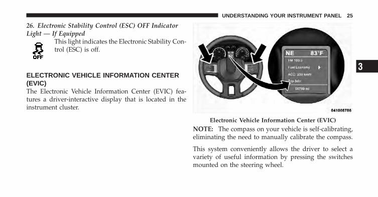
26. Electronic Stability Control (ESC) OFF IndicatorLight — If Equipped
This light indicates the Electronic Stability Con-trol (ESC) is off.
ELECTRONIC VEHICLE INFORMATION CENTER(EVIC)The Electronic Vehicle Information Center (EVIC) fea-tures a driver-interactive display that is located in theinstrument cluster.
NOTE: The compass on your vehicle is self-calibrating,eliminating the need to manually calibrate the compass.
This system conveniently allows the driver to select avariety of useful information by pressing the switchesmounted on the steering wheel.
Electronic Vehicle Information Center (EVIC)
3
UNDERSTANDING YOUR INSTRUMENT PANEL 25
Refer to “Electronic Vehicle Information Center – IfEquipped” in the Owner’s Manual for further informa-tion.
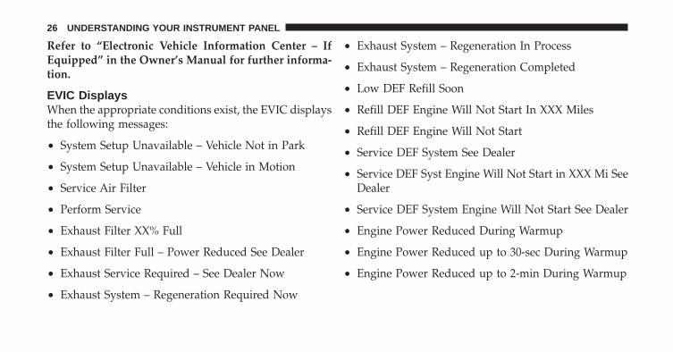
EVIC DisplaysWhen the appropriate conditions exist, the EVIC displaysthe following messages:
• System Setup Unavailable – Vehicle Not in Park
• System Setup Unavailable – Vehicle in Motion
• Service Air Filter
• Perform Service
• Exhaust Filter XX% Full
• Exhaust Filter Full – Power Reduced See Dealer
• Exhaust Service Required – See Dealer Now
• Exhaust System – Regeneration Required Now
• Exhaust System – Regeneration In Process
• Exhaust System – Regeneration Completed
• Low DEF Refill Soon
• Refill DEF Engine Will Not Start In XXX Miles
• Refill DEF Engine Will Not Start
• Service DEF System See Dealer
• Service DEF Syst Engine Will Not Start in XXX Mi SeeDealer
• Service DEF System Engine Will Not Start See Dealer
• Engine Power Reduced During Warmup
• Engine Power Reduced up to 30-sec During Warmup
• Engine Power Reduced up to 2-min During Warmup
26 UNDERSTANDING YOUR INSTRUMENT PANEL
EVIC Warning Lights
• Water In Fuel Indicator LightThe “Water In Fuel Indicator Light” will illu-minate when there is water detected in the fuelfilter. If this light remains on, DO NOT start thevehicle before you drain the water from the
fuel filter to prevent engine damage. Refer to “Mainte-nance Procedures/ Draining Fuel/Water Separator Fil-ter” in “Maintaining Your Vehicle” for further informa-tion.
• Wait To Start LightThe “Wait To Start Light” will illuminate when theignition is turned to the RUN position and the
intake manifold temperature is below 66°F (19°C). Waituntil the “Wait To Start Light” turns OFF, then start thevehicle. Refer to “Starting Procedures” in “Starting andOperating” for further information.
NOTE: The “Wait To Start Light” may not illuminate ifthe intake manifold temperature is warm enough.
Turbocharger Derate Mode MessagesThe vehicle will display messages when a derate isactivated to protect the turbocharger during engine startup in cold ambient temperatures.
• Engine Power Reduced During Warmup - This mes-sage will display during start up when the ambienttemperature is between 10° F (-12° C) and -10° F(-23° C).
• Engine Power Reduced Up To 30 Sec (Seconds)During Warmup - This message will display duringstart up when the ambient temperature is between-10° F (-23° C) and -25 F (-32° C).
3
UNDERSTANDING YOUR INSTRUMENT PANEL 27
• Engine Power Reduced Up To 2 Min (Minutes)During Warmup - This message will display duringstart up when the ambient temperature is -25° F(-32° C) and below.
Diesel Exhaust Fluid (DEF) Warning Messages –Chassis Cab OnlyYour vehicle will begin displaying warning messageswhen the DEF level reaches a driving range of approxi-mately 1,000 miles (1 609 km). If the following warningmessage sequence is ignored, your vehicle will not startunless DEF is added.
• Low DEF Refill Soon – This message will displaywhen the low level is reached, during vehicle start up,and with increased frequency during vehicle opera-tion. It will be accompanied by a single chime. Ap-proximately 6 gallons (23 Liters) of DEF is required torefill the tank when this message is initially displayed.
• Refill DEF Engine Will Not Restart In XXX Miles –This message will continuously display if the “LowDEF Refill Soon” message is ignored, and the fre-quency of occurance of the chime will increase unlessup to 2 gallons (7.5 Liters) of DEF is added to the tank.The engine will not restart if the mileage counterreaches zero.
• Refill DEF Engine Will Not Start – This message willcontinuously display when the counter reaches zero,and will be accompanied by a periodic chime. Theengine will not start after it has been turned off unlessup to 2.5 gallons (9.5 Liters) of DEF is added to thetank.
NOTE: A minimum of up to 2.5 gallons (9.5 Liters) maybe required to restart the engine. Although the vehiclewill continue to operate while this warning message isinitially displayed, the engine will not restart the nexttime the vehicle is shut off.
28 UNDERSTANDING YOUR INSTRUMENT PANEL
Diesel Exhaust Fluid (DEF) Fault WarningMessages – Chassis Cab OnlyThere are three different messages which are displayed ifthe vehicle detects that the DEF system has been filledwith a fluid other than DEF, has experienced componentfailures, or when tampering has been detected. Thevehicle will not start if the DEF system is not servicedwithin less than 250 miles (402 km) of the fault beingdetected.
When the DEF system needs to be serviced the followingwarnings will display:
• Service DEF System – See Dealer — This messagewill display when the fault is initially detected, eachtime the vehicle is started, and periodically duringdriving. The message will be accompanied by a singlechime. We recommend you drive to your nearestauthorized dealer and have your vehicle serviced assoon as possible.
• Service DEF System Engine Will Not Start In200 Miles – See Dealer — This message will display ifthe DEF system has not been serviced after the “Ser-vice DEF System – See Dealer” message is displayed.This message will continuously display until the mile-age counter reaches zero, and will be accompanied bya periodic chime. The message will continue to count-down until it reaches zero unless the vehicle is ser-viced. We recommend you drive to your nearestauthorized dealer and have your vehicle servicedimmediately.
NOTE: Under some circumstances this mileage countermay start with a value of less than 200 miles (322 km). Forexample, if recurring faults are detected in a time intervalof less than 40 hours, the counter may restart at the valuewhere it stopped when a previous fault was temporarilyremedied, or at a minimum of 50 miles (80 km).
3
UNDERSTANDING YOUR INSTRUMENT PANEL 29
• Service DEF System Engine Will Not Start – SeeDealer — This message will continuously displaywhen the mileage counter reaches zero, and will beaccompanied by a periodic chime. The engine will notrestart after it has been turned off, your vehicle willrequire towing, see your authorized dealer for service.
NOTE: When this message is displayed, the engine willno longer start after it has been turned off.
Vehicle Information (Customer InformationFeatures)Press and release the UP or DOWN button until “VehicleInfo” displays in the EVIC and press the SELECT button.Press the UP and DOWN button to scroll through theavailable information displays, then press SELECT todisplay anyone of the following choices.
• DEF Fluid Level – Chassis Cab OnlyDisplays the Diesel Exhaust Fluid (DEF) fluid level.
• Coolant TempDisplays the actual coolant temperature.
• Oil PressureDisplays the actual oil pressure.
• Trans TemperatureDisplays the actual transmission sump temperature.
• Engine HoursDisplays the hours of engine operation.
30 UNDERSTANDING YOUR INSTRUMENT PANEL
STARTING AND OPERATING
CONTENTS
� Starting Procedures . . . . . . . . . . . . . . . . . . . . . 34
▫ Manual Transmission – If Equipped . . . . . . . . 34
▫ Automatic Transmission – If Equipped . . . . . . 34
▫ Extreme Cold Weather . . . . . . . . . . . . . . . . . . 35
▫ Normal Starting Procedure – Engine ManifoldAir Temperature Above 66°F (19°C) . . . . . . . . . 35
▫ Starting Procedure – Engine Manifold AirTemperature 0°F To 66°F (–18°C To 19°C) . . . . 37
▫ Starting Procedure – Engine Manifold AirTemperature Below 0°F (-18°C) . . . . . . . . . . . . 38
▫ Starting Fluids . . . . . . . . . . . . . . . . . . . . . . . 40
� Normal Operation – Diesel Engine . . . . . . . . . . 41
▫ Cold Weather Precautions . . . . . . . . . . . . . . . 41
▫ Engine Idling . . . . . . . . . . . . . . . . . . . . . . . . 44
▫ Stopping The Engine . . . . . . . . . . . . . . . . . . . 45
▫ Idle Shutdown (Chassis Cab Only) . . . . . . . . . 46
▫ Programmable Maximum Vehicle Speed(Chassis Cab Only) . . . . . . . . . . . . . . . . . . . . 46
▫ Snow Plow Mode . . . . . . . . . . . . . . . . . . . . . 47
4
▫ Operating Precautions . . . . . . . . . . . . . . . . . . 47
▫ Cooling System Tips – AutomaticTransmission . . . . . . . . . . . . . . . . . . . . . . . . 48
� Engine Block Heater — If Equipped . . . . . . . . . 49
▫ Block Heater Usage . . . . . . . . . . . . . . . . . . . . 50
� Diesel Exhaust Brake (Engine Braking)— If Equipped . . . . . . . . . . . . . . . . . . . . . . . . . 50
� Automatic Transmission — If Equipped . . . . . . . 52
▫ Key Ignition Park Interlock . . . . . . . . . . . . . . 53
▫ Brake/Transmission Shift Interlock System . . . 53
▫ Six-Speed Automatic Transmission– If Equipped (Ram Truck Only) . . . . . . . . . . . 54
▫ Six-Speed Automatic Transmission– If Equipped (Chassis Cab Only) . . . . . . . . . . 64
� Manual Transmission — If Equipped . . . . . . . . . 75
▫ Shifting . . . . . . . . . . . . . . . . . . . . . . . . . . . . 75
▫ Downshifting . . . . . . . . . . . . . . . . . . . . . . . . 76
▫ Reverse Shifting . . . . . . . . . . . . . . . . . . . . . . 78
� Power Take Off Operation — If Equipped(Chassis Cab Only) . . . . . . . . . . . . . . . . . . . . . . 78
▫ Stationary Mode . . . . . . . . . . . . . . . . . . . . . . 79
▫ Mobile Mode . . . . . . . . . . . . . . . . . . . . . . . . 80
▫ Power Take Off – Aftermarket Installation . . . . 81
� Engine Runaway . . . . . . . . . . . . . . . . . . . . . . . 81
� Fuel Requirements . . . . . . . . . . . . . . . . . . . . . . 82
▫ Fuel Specifications . . . . . . . . . . . . . . . . . . . . 83
� Adding Fuel . . . . . . . . . . . . . . . . . . . . . . . . . . 83
32 STARTING AND OPERATING
▫ Fuel Filler Cap . . . . . . . . . . . . . . . . . . . . . . . 84
▫ Avoid Using Contaminated Fuel . . . . . . . . . . . 84
▫ Bulk Fuel Storage – Diesel Fuel . . . . . . . . . . . 84
▫ Diesel Exhaust Fluid Storage . . . . . . . . . . . . . 85
▫ Adding Diesel Exhaust Fluid – Chassis CabOnly . . . . . . . . . . . . . . . . . . . . . . . . . . . . . . 86
� Diesel Exhaust Fluid — Chassis Cab Only . . . . . 88
▫ System Overview . . . . . . . . . . . . . . . . . . . . . 88
4
STARTING AND OPERATING 33
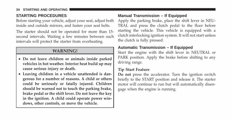
STARTING PROCEDURESBefore starting your vehicle, adjust your seat, adjust bothinside and outside mirrors, and fasten your seat belts.The starter should not be operated for more than 15-second intervals. Waiting a few minutes between suchintervals will protect the starter from overheating.
WARNING!
• Do not leave children or animals inside parkedvehicles in hot weather. Interior heat build up maycause serious injury or death.
• Leaving children in a vehicle unattended is dan-gerous for a number of reasons. A child or otherscould be seriously or fatally injured. Childrenshould be warned not to touch the parking brake,brake pedal or the shift lever. Do not leave the keyin the ignition. A child could operate power win-dows, other controls, or move the vehicle.
Manual Transmission – If EquippedApply the parking brake, place the shift lever in NEU-TRAL and press the clutch pedal to the floor beforestarting the vehicle. This vehicle is equipped with aclutch interlocking ignition system. It will not start unlessthe clutch is fully pressed.
Automatic Transmission – If EquippedStart the engine with the shift lever in NEUTRAL orPARK position. Apply the brake before shifting to anydriving range.
Tip Start FeatureDo not press the accelerator. Turn the ignition switchbriefly to the START position and release it. The startermotor will continue to run but will automatically disen-gage when the engine is running.
34 STARTING AND OPERATING
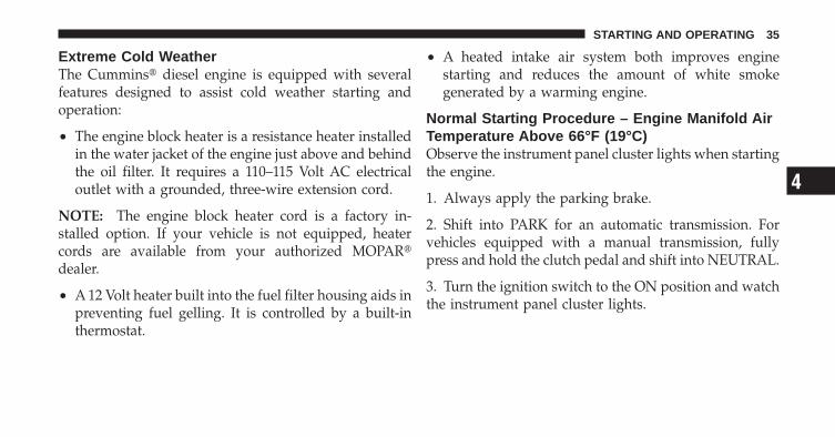
Extreme Cold WeatherThe Cummins� diesel engine is equipped with severalfeatures designed to assist cold weather starting andoperation:
• The engine block heater is a resistance heater installedin the water jacket of the engine just above and behindthe oil filter. It requires a 110–115 Volt AC electricaloutlet with a grounded, three-wire extension cord.
NOTE: The engine block heater cord is a factory in-stalled option. If your vehicle is not equipped, heatercords are available from your authorized MOPAR�dealer.
• A 12 Volt heater built into the fuel filter housing aids inpreventing fuel gelling. It is controlled by a built-inthermostat.
• A heated intake air system both improves enginestarting and reduces the amount of white smokegenerated by a warming engine.
Normal Starting Procedure – Engine Manifold AirTemperature Above 66°F (19°C)Observe the instrument panel cluster lights when startingthe engine.
1. Always apply the parking brake.
2. Shift into PARK for an automatic transmission. Forvehicles equipped with a manual transmission, fullypress and hold the clutch pedal and shift into NEUTRAL.
3. Turn the ignition switch to the ON position and watchthe instrument panel cluster lights.
4
STARTING AND OPERATING 35
CAUTION!
If the “Water in Fuel Indicator Light” remains on, DONOT START the engine before you drain the waterfrom the fuel filter to avoid engine damage. Refer to“Maintenance Procedures/Draining Fuel/Water Sepa-rator Filter” in “Maintaining Your Vehicle” for fur-ther information.
4. Turn the ignition switch to the START position andcrank the engine. Do not press the accelerator duringstarting.
CAUTION!
Do not crank engine for more than 15 seconds at atime or starter motor damage may result. Turn theignition switch to the OFF position and wait at leasttwo minutes for the starter to cool before repeatingstart procedure.
5. When the engine starts, release the key fob.
6. Check to see that there is oil pressure.
7. Release the parking brake.
36 STARTING AND OPERATING

Starting Procedure – Engine Manifold AirTemperature 0°F To 66°F (–18°C to 19°C)
NOTE: The temperature displayed in the ElectronicVehicle Information Center (EVIC) does not necessarilyreflect the engine manifold air temperature. Refer to“Electronic Vehicle Information Center (EVIC)” in “Un-derstanding Your Instrument Panel” for further informa-tion. When engine temperatures fall below 66°F (19°C)the “Wait To Start Light” will remain on indicating theintake manifold heater system is active.
Follow the steps in the “Normal Starting” procedureexcept:
1. The “Wait To Start Light” will remain on for a periodof time (length of time depends on engine temperature).
CAUTION!
If the “Water in Fuel Indicator Light” remains on, DONOT START engine before you drain the water fromthe fuel filter to avoid engine damage. Refer to“Maintenance Procedures/Draining Fuel/Water Sepa-rator Filter” in “Maintaining Your Vehicle” for fur-ther information.
2. After the “Wait To Start Light” goes off, turn theignition switch to the START position. Do not press theaccelerator during starting.
4
STARTING AND OPERATING 37
CAUTION!
Do not crank engine for more than 15 seconds at atime or starter motor damage may result. Turn theignition switch to the OFF position and wait at leasttwo minutes for the starter to cool before repeatingstart procedure.
3. After engine start-up, check to see that there is oilpressure.
4. Allow the engine to idle about three minutes until themanifold heaters have completed the post-heat cycle.
5. Release the parking brake and drive.
NOTE:• Engine idle speed will automatically increase to 1,000
RPM and engage the Variable Geometry Turbochargerat low coolant temperatures to improve engine warm-up.
• If the engine stalls, or if the ignition switch is left ONfor more than two minutes after the “Wait To StartLight” goes out, reset the grid heaters by turning theignition switch to the OFF position for at least fiveseconds and then back ON. Repeat steps 1 through 5 of“Starting Procedure – Engine Manifold Air Tempera-ture Below 66°F (19°C).”
Starting Procedure – Engine Manifold AirTemperature Below 0°F (-18°C)In extremely cold weather below 0°F (-18°C) it may bebeneficial to cycle the manifold heaters twice beforeattempting to start the engine. This can be accomplishedby turning the ignition OFF for at least five seconds andthen back ON after the “Wait To Start Light” has turnedoff, but before the engine is started. However, excessivecycling of the manifold heaters will result in damage tothe heater elements or reduced battery voltage.
38 STARTING AND OPERATING
NOTE: If multiple pre-heat cycles are used beforestarting, additional engine run time may be required tomaintain battery state of charge at a satisfactory level.
1. If the engine stalls after the initial start, the ignitionmust be turned to the OFF position for at least fiveseconds and then to the ON position to recycle themanifold heaters.
NOTE: Excessive white smoke and poor engine perfor-mance will result if manifold heaters are not recycled.
2. Heat generated by the manifold heaters dissipatesrapidly in a cold engine. If more than two minutes passbetween the time the “Wait To Start Light” turns off andthe engine is started, recycle the manifold heaters byturning the ignition switch to the OFF position for at leastfive seconds and then back ON.
3. If the vehicle is driven and vehicle speed exceeds19 mph (31 km/h) before the manifold heater post-heat(after start) cycle is complete, the manifold heaters willshut off.
4. If the engine is started before the “Wait To Start Light”turns off, the preheat cycle will turn off.
5. If the engine is cranked for more than 10 seconds, thepost-heat cycle will turn off.
NOTE:• Engine idle speed will automatically increase to 1,000
RPM and engage the Variable Geometry Turbochargerat low coolant temperatures to improve engine warm-up.
4
STARTING AND OPERATING 39
• When a diesel engine is allowed to run out of fuel orthe fuel gels at low temperatures, air is pulled into thefuel system. If your engine has run out of fuel, refer to“Maintenance Procedures/Priming If The Engine HasRun Out Of Fuel” in “Maintaining Your Vehicle” forfurther information.
Starting Fluids
WARNING!
Starting fluids or flammable liquids are never to beused in the Cummins� diesel engine (see Warninglabel). Never pour diesel fuel, flammable liquid,starting fluids (ether) into the air cleaner canister, airintake piping, or turbocharger inlet in an attempt tostart the vehicle. This could result in a flash fire andexplosion causing serious personal injury and enginedamage.
The engine is equipped with an automatic electric airpreheating system. If the instructions in this manual arefollowed, the engine should start in all conditions.
WARNING!
• Do not leave children or animals inside parkedvehicles in hot weather. Interior heat build up maycause serious injury or death.
• Leaving children in a vehicle unattended is dan-gerous for a number of reasons. A child or otherscould be seriously or fatally injured. Childrenshould be warned not to touch the parking brake,brake pedal or the shift lever. Do not leave the keyin the ignition. A child could operate power win-dows, other controls, or move the vehicle.
40 STARTING AND OPERATING
NORMAL OPERATION – DIESEL ENGINEObserve the following when the engine is operating.
• All message center lights are off.
• Malfunction Indicator Light (MIL) is off.
• Engine oil pressure is above 10 psi (69 kPa) at idle.
• Voltmeter operation:
• The voltmeter may show a gauge fluctuation atvarious engine temperatures. This cycling operationis caused by the post-heat cycle of the intake mani-fold heater system. The number of cycles and thelength of the cycling operation is controlled by theengine control module. Post-heat operation can runfor several minutes, and then the electrical systemand voltmeter needle will stabilize.
• The cycling action will cause temporary dimming ofthe headlamps, interior lamps, and also a noticeablereduction in blower motor speed.
Cold Weather PrecautionsOperation in ambient temperature below 32°F (0°C) mayrequire special considerations. The following charts sug-gest these options:
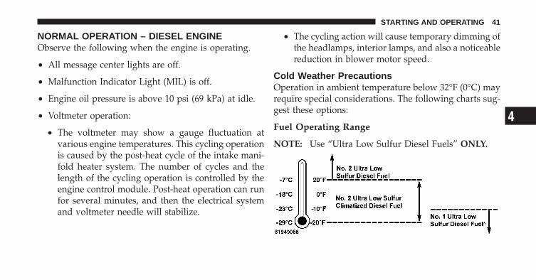
Fuel Operating Range
NOTE: Use “Ultra Low Sulfur Diesel Fuels” ONLY.
4
STARTING AND OPERATING 41
*No. 1 Ultra Low Sulfur Diesel Fuel should only be usedwhere extended arctic conditions (-10°F/-23°C) exist.
NOTE:• Use of Climatized Ultra Low Sulfur Diesel Fuel or
Number 1 Ultra Low Sulfur Diesel Fuel results in anoticeable decrease in fuel economy.
• Climatized Ultra Low Sulfur Diesel Fuel is a blend ofNumber 2 Ultra Low Sulfur and Number 1 Ultra LowSulfur Diesel Fuels which reduces the temperature atwhich wax crystals form in fuel.
• The engine requires the use of “Ultra Low SulfurDiesel Fuel”. Use of incorrect fuel could result inengine and exhaust system damage. Refer to “FuelRequirements” in “Starting and Operating” for furtherinformation.
Engine Oil UsageRefer to “Maintenance Procedures” in “Maintaining YourVehicle” for the correct engine oil viscosity.
Winter Front UsageIf a winter front or cold weather cover is to be used, apercentage of the total grille opening area must be leftuncovered to provide sufficient air flow to the charge aircooler and automatic transmission oil cooler. The per-centage of opening must be increased with the increasingambient air temperature and/or engine load. If thecooling fan can be heard cycling frequently, increase thesize of the opening in the winter front. A suitable coldweather cover is available from your MOPAR� dealer.
42 STARTING AND OPERATING
Battery Blanket UsageA battery loses 60% of its cranking power as the batterytemperature decreases to 0°F (-18°C). For the same de-crease in temperature, the engine requires twice as muchpower to crank at the same RPM. The use of 120 VACpowered battery blankets will greatly increase startingcapability at low temperatures. Suitable battery blanketsare available from your authorized MOPAR� dealer.
Engine Warm-UpAvoid full throttle operation when the engine is cold.When starting a cold engine, bring the engine up tooperating speed slowly to allow the oil pressure tostabilize as the engine warms up.
NOTE: High-speed, no-load running of a cold enginecan result in excessive white smoke and poor engineperformance. No-load engine speeds should be keptunder 1,200 RPM during the warm-up period, especiallyin cold ambient temperature conditions.
Your vehicle is equipped with a turbo speed limiter, thisfeature limits the engine speed to 1,200 RPM whenengine coolant temperatures are below 70°F (21°C). Thisfeature is designed to protect the turbocharger fromdamage and will only operate in PARK or NEUTRAL.
If temperatures are below 32°F (0°C), operate the engineat moderate speeds for five minutes before full loads areapplied.
NOTE:• If ambient temperatures are low and the coolant
temperature is below 180°F (82°C), the engine idlespeed will slowly increase to 1,000 RPM after twominutes of idle, if the following conditions are met:
• foot is off brake pedal and throttle pedal
• automatic transmission is in PARK
• vehicle speed is zero
• Applying the throttle will cancel fast idle
4
STARTING AND OPERATING 43
• If the engine is equipped with an exhaust brake,operating the exhaust brake at idle will greatly im-prove warm up rate and will help keep the engineclose to operating temperature during extended idle.
Engine IdlingAvoid prolonged idling, long periods of idling may beharmful to your engine because combustion chambertemperatures can drop so low that the fuel may not burncompletely. Incomplete combustion allows carbon andvarnish to form on piston rings, engine valves, andinjector nozzles. Also, the unburned fuel can enter thecrankcase, diluting the oil and causing rapid wear to theengine.
If the engine is allowed to idle, under some conditionsthe idle speed may increase to 900 RPM then return tonormal idle speed. This is normal operation.
NOTE: For EVIC messages related to the vehicle’sexhaust system, refer to “Maintenance Procedures/Intervention Regeneration Strategy – EVIC Message Pro-cess Flow” in “Maintaining Your Vehicle” for furtherinformation.
Idle-Up Feature – Automatic Transmission OnlyThe driver-controlled high idle speed feature will helpincrease cylinder temperatures and provide additionalcab heat, however, excessive idling may still cause theexhaust aftertreatment system to not properly regenerate.Extended periods of idle time should be avoided.
The Idle-Up feature uses the speed control switches toincrease engine idle speed and quickly warm the vehi-cle’s interior.
1. With the transmission in PARK, the parking brakeapplied, and the engine running, press the speed controlswitch to the ON position, then press the SET switch.
44 STARTING AND OPERATING
2. The engine RPM will go up to 1100 RPM. To increasethe RPM, press and hold the ACCEL/RESUME switchand the idle speed will increase to approximately 1500RPM. To decrease the RPM, press and hold the DECELswitch and the idle speed will decrease to approximately1100 RPM.
3. To cancel the Idle–Up feature, either press the CAN-CEL switch, press the ON/OFF switch, or press the brakepedal.
Stopping The EngineIdle the engine a few minutes before routine shutdown.After full load operation, idle the engine three to fiveminutes before shutting it down. This idle period willallow the lubricating oil and coolant to carry excess heataway from the combustion chamber, bearings, internalcomponents, and turbocharger. This is especially impor-tant for turbocharged, charge air-cooled engines.
NOTE:• During engine shut down on vehicles equipped with
manual transmissions, it is normal for the dieselengine to resonate heavily for a moment during engineshut off. When the engine is connected to a manualtransmission, this resonance causes load gear rattlefrom the transmission. This is commonly referred to as“shut down rattle.” The manufacturer recommendsperforming engine shut down with the clutch pedalpushed to the floor (clutch disengaged). When engineshut down is performed in this manner the rattle isreduced (not eliminated).
4
STARTING AND OPERATING 45
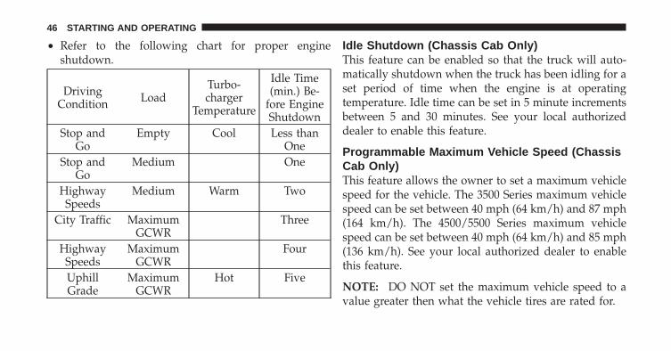
• Refer to the following chart for proper engineshutdown.
DrivingCondition Load
Turbo-charger
Temperature
Idle Time(min.) Be-
fore EngineShutdown
Stop andGo
Empty Cool Less thanOne
Stop andGo
Medium One
HighwaySpeeds
Medium Warm Two
City Traffic MaximumGCWR
Three
HighwaySpeeds
MaximumGCWR
Four
UphillGrade
MaximumGCWR
Hot Five
Idle Shutdown (Chassis Cab Only)This feature can be enabled so that the truck will auto-matically shutdown when the truck has been idling for aset period of time when the engine is at operatingtemperature. Idle time can be set in 5 minute incrementsbetween 5 and 30 minutes. See your local authorizeddealer to enable this feature.
Programmable Maximum Vehicle Speed (ChassisCab Only)This feature allows the owner to set a maximum vehiclespeed for the vehicle. The 3500 Series maximum vehiclespeed can be set between 40 mph (64 km/h) and 87 mph(164 km/h). The 4500/5500 Series maximum vehiclespeed can be set between 40 mph (64 km/h) and 85 mph(136 km/h). See your local authorized dealer to enablethis feature.
NOTE: DO NOT set the maximum vehicle speed to avalue greater then what the vehicle tires are rated for.
46 STARTING AND OPERATING
Snow Plow ModeSnow Plow Mode can be activated when the vehicle hasa snow plow installed. This mode fully engages the fanclutch to increase the airflow when the plow is attachedto the vehicle.
NOTE: There may be an increase in fan noise and adecrease in fuel economy may result when using thisfeature. The fan clutch operation can be initiated byperforming the following button sequence.
1. Turn the ignition key to the on position or start thevehicle.
2. Pull in the Cruise Control “Cancel” button/lever andhold. While holding the Cruise Control “Cancel”, pushthe “Exhaust Brake” button twice within five seconds.Repeat this sequence four times. The chime will soundtwice as an audible indicator that the function is engaged.
3. To disable the function, repeat Step 2. The chime willsound four times as an audible indicator that the functionis disengaged.
Operating Precautions
Avoid Overheating The EngineThe temperature of the engine coolant (antifreeze) (amixture of 50% ethylene-glycol and 50% water) must notexceed the normal range of the temperature gauge 240°F(116°C) with a 16 psi (110 kPa) radiator cap.
Usually the engine coolant (antifreeze) temperature indi-cated during operation will be to the left of center in thenormal range of the gauge.
Avoid Low Coolant Temperature OperationContinual operation at low engine coolant (antifreeze)temperature below the normal range on the gauge 140°F(60°C) can be harmful to the engine. Low engine coolant
4
STARTING AND OPERATING 47
(antifreeze) temperature can cause incomplete combus-tion which allows carbon and varnish to form on pistonrings and injector nozzles. Also, the unburned fuel canenter the crankcase, diluting the lubricating oil andcausing rapid wear to the engine.
Cooling System Tips – Automatic TransmissionTo reduce potential for engine and transmission over-heating in high ambient temperature conditions, take thefollowing actions:
• City Driving —When stopped, shift the transmission into NEUTRALand increase engine idle speed.
• Highway Driving —Reduce your speed.
• Up Steep Hills —Select a lower transmission gear, but try and keep thetorque converter clutch engaged.
• Air Conditioning —Turn it off temporarily.
Do Not Operate The Engine With Low OilPressureWhen the engine is at normal operating temperature, theminimum oil pressures required are:
Idle 700 to 800 RPM . . . . . . . . . . . . . . . 10 psi (69 kPa)Full speed and load . . . . . . . . . . . . . . 30 psi (207 kPa)
CAUTION!
If oil pressure falls to less than normal readings, shutthe engine off immediately. Failure to do so couldresult in immediate and severe engine damage.
48 STARTING AND OPERATING

Do Not Operate The Engine With Failed PartsPractically all failures give some warning before the partsfail. Be on the alert for changes in performance, sounds,and visual evidence that the engine requires service.Some important clues are:
• engine misfiring or vibrating severely
• sudden loss of power
• unusual engine noises
• fuel, oil or coolant leaks
• sudden change, outside the normal operating range, inthe engine operating temperature
• excessive smoke
• oil pressure drop
ENGINE BLOCK HEATER — IF EQUIPPEDThe engine block heater warms engine coolant andpermits quicker starts in cold weather. Connect the heatercord to a ground-fault interrupter protected 110–115 VoltAC electrical outlet with a grounded, three-wire exten-sion cord.
The engine block heater cord is routed under the hood tothe right side and can be located just behind the grillenear the headlamp.
NOTE: The engine block heater cord is a factory in-stalled option. If your vehicle is not equipped, heatercords are available from your authorized MOPAR�dealer.
The block heater must be plugged in at least one hour tohave an adequate warming effect on the coolant.
4
STARTING AND OPERATING 49
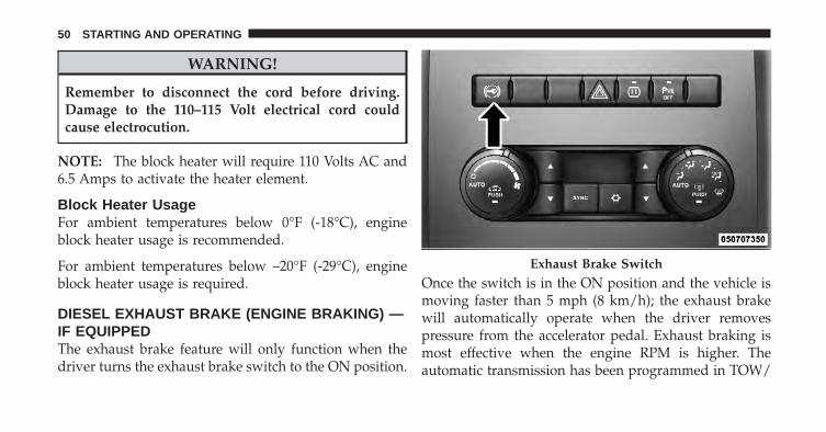
WARNING!
Remember to disconnect the cord before driving.Damage to the 110–115 Volt electrical cord couldcause electrocution.
NOTE: The block heater will require 110 Volts AC and6.5 Amps to activate the heater element.
Block Heater UsageFor ambient temperatures below 0°F (-18°C), engineblock heater usage is recommended.
For ambient temperatures below –20°F (-29°C), engineblock heater usage is required.
DIESEL EXHAUST BRAKE (ENGINE BRAKING) —IF EQUIPPEDThe exhaust brake feature will only function when thedriver turns the exhaust brake switch to the ON position.
Once the switch is in the ON position and the vehicle ismoving faster than 5 mph (8 km/h); the exhaust brakewill automatically operate when the driver removespressure from the accelerator pedal. Exhaust braking ismost effective when the engine RPM is higher. Theautomatic transmission has been programmed in TOW/
Exhaust Brake Switch
50 STARTING AND OPERATING
HAUL mode only to downshift more aggressively whenthe exhaust brake is enabled to increase brake perfor-mance.
CAUTION!
Use of aftermarket exhaust brakes is not recom-mended and could lead to engine damage
WARNING!
Do not use the exhaust brake feature when driving inicy or slippery conditions as the increased enginebraking can cause the rear wheels to slide and thevehicle to swing around with the possible loss ofvehicle control, which may cause an accident possi-bly resulting in personal injury or death.
NOTE: For optimum braking power it is recommendedto use the exhaust brake while in TOW/HAUL mode.
The purpose of the exhaust brake (engine braking) fea-ture is to supply negative (braking) torque to the engine.Typically, the engine braking is used for, but not limitedto, vehicle towing applications where vehicle braking canbe achieved by the internal engine power, thereby spar-ing the mechanical brakes of the vehicle.
Benefits of the exhaust brake are:
• vehicle driving control
• reduced brake fade
• longer brake life
• faster cab warm-up.
The exhaust brake feature can also be used to reduce theengine warm up time. To use the exhaust brake as awarm-up device, the vehicle must be stopped or movingless than 5 mph (8 km/h), the exhaust brake switch must
4
STARTING AND OPERATING 51
be in the ON position, and the coolant temperature mustbe below 180°F (82°C) and ambient temperature below60°F (16°C).
AUTOMATIC TRANSMISSION — IF EQUIPPED
CAUTION!
Damage to the transmission may occur if the follow-ing precautions are not observed:• Shift into PARK only after the vehicle has come to
a complete stop.• Shift into or out of REVERSE only after the
vehicle has come to a complete stop and the engineis at idle speed.
• Do not shift between PARK, REVERSE, NEU-TRAL, or DRIVE into any forward gear when theengine is above idle speed.
(Continued)
CAUTION! (Continued)• Before shifting into any gear, make sure your foot
is firmly pressing on the brake pedal.
WARNING!
• Unintended movement of a vehicle could injurethose in and near the vehicle. As with all vehicles,you should never exit a vehicle while the engine isrunning. Before exiting a vehicle, apply the park-ing brake, shift the transmission into PARK, andremove the key fob. Once the key fob is removed,the shift lever is locked in the PARK position,securing the vehicle against unwanted movement.Furthermore, you should never leave unattendedchildren inside a vehicle.
(Continued)
52 STARTING AND OPERATING
WARNING! (Continued)• Leaving children in a vehicle unattended is dan-
gerous for a number of reasons. A child or otherscould be seriously or fatally injured. Childrenshould be warned not to touch the parking brake,brake pedal or the shift lever. Do not leave the keyfob in the vehicle. A child could operate powerwindows, other controls, or move the vehicle.
• It is dangerous to move the shift lever out of PARKor NEUTRAL if the engine speed is higher thanidle speed. If your foot is not firmly pressing onthe brake pedal, the vehicle could acceleratequickly forward or in reverse. You could losecontrol of the vehicle and hit someone or some-thing. Only shift into gear when the engine isidling normally and when your right foot is firmlypressing on the brake pedal.
Key Ignition Park InterlockThis vehicle is equipped with a Key Ignition Park Inter-lock which requires the shift lever to be placed in PARKbefore the ignition switch can be turned to the LOCK/OFF position. The key fob can only be removed from theignition when the ignition is in the LOCK/OFF positionand once removed the shift lever is locked in PARK.
Brake/Transmission Shift Interlock SystemThis vehicle is equipped with a Brake Transmission ShiftInterlock System (BTSI) that holds the shift lever in thePARK position when the ignition switch is in the LOCK/OFF position. To move the shift lever out of the PARKposition, the ignition switch must be turned to theON/RUN position (engine running or not) and the brakepedal must be pressed.
4
STARTING AND OPERATING 53
Six-Speed Automatic Transmission – If Equipped(Ram Truck Only)The shift lever position display (located in the instrumentpanel cluster) indicates the transmission gear range. Theshift lever is mounted on the right side of the steeringcolumn. You must press the brake pedal to move the shiftlever out of the PARK position (refer to “Brake/Transmission Shift Interlock System” in this section). Todrive, move the shift lever from PARK or NEUTRAL tothe DRIVE position. Pull the shift lever toward you whenshifting into REVERSE or PARK, or when shifting out ofPARK.
The electronically-controlled transmission provides aprecise shift schedule. The transmission electronics areself-calibrating; therefore, the first few shifts on a newvehicle may be somewhat abrupt. This is a normalcondition, and precision shifts will develop within a fewhundred miles (kilometers).
Shifting from DRIVE to PARK or REVERSE should bedone only after the accelerator pedal is released and thevehicle is stopped. Be sure to keep your foot on the brakepedal when moving the shift lever between these gears.
The transmission shift lever has only Park, Reverse,Neutral, and Drive shift positions. Manual downshiftscan be made using the Electronic Range Select (ERS) shiftcontrol (described later). Pressing the ERS (-/+) buttonswhile in the DRIVE position will select the highestavailable transmission gear, and will display that gear inthe instrument cluster as 6, 5, 4, 3, 2, 1.
Gear RangesDO NOT race the engine when shifting from PARK orNEUTRAL into another gear range.
PARKThis range supplements the parking brake by locking thetransmission. The engine can be started in this range.
54 STARTING AND OPERATING
Never attempt to use PARK while the vehicle is inmotion. Apply the parking brake when leaving thevehicle in this range.
When parking on a level surface, you may place the shiftlever in the PARK position first, and then apply theparking brake.
When parking on a hill, apply the parking brake beforeplacing the shift lever in PARK, otherwise the load on thetransmission locking mechanism may make it difficult tomove the shift lever out of PARK. As an added precau-tion, turn the front wheels toward the curb on a downhillgrade and away from the curb on an uphill grade.
WARNING!
• Never use the PARK position as a substitute forthe parking brake. Always apply the parkingbrake fully when parked to guard against vehiclemovement and possible injury or damage.
• Your vehicle could move and injure you and othersif it is not completely in PARK. Check by trying tomove the shift lever clockwise without first pull-ing it toward you after you have placed it in PARK.Make sure the transmission is in PARK beforeleaving the vehicle.
(Continued)
4
STARTING AND OPERATING 55

WARNING! (Continued)• It is dangerous to move the shift lever out of PARK
or NEUTRAL if the engine speed is higher thanidle speed. If your foot is not firmly pressing onthe brake pedal, the vehicle could acceleratequickly forward or in reverse. You could losecontrol of the vehicle and hit someone or some-thing. Only shift into gear when the engine isidling normally and when your foot is firmlypressing on the brake pedal.
(Continued)
WARNING! (Continued)• Unintended movement of a vehicle could injure
those in and near the vehicle. As with all vehicles,you should never exit a vehicle while the engine isrunning. Before exiting a vehicle, always apply theparking brake, shift the transmission into PARK,and remove the key fob. Once the key fob isremoved, the shift lever is locked in the PARKposition, securing the vehicle against unwantedmovement. Furthermore, you should never leaveunattended children inside a vehicle.
• Never leave children alone in a vehicle. Leavingunattended children in a vehicle is dangerous for anumber of reasons. A child or others could beseriously or fatally injured. Do not leave the keyfob in the vehicle. A child could operate powerwindows, other controls, or move the vehicle.
56 STARTING AND OPERATING
CAUTION!
• Before moving the shift lever out of PARK, youmust turn the ignition switch from the LOCK/OFFposition to the ON/RUN position, and also pressthe brake pedal. Otherwise, damage to the shiftlever could result.
• DO NOT race the engine when shifting fromPARK or NEUTRAL into another gear range, asthis can damage the drivetrain.
The following indicators should be used to ensure thatyou have engaged the shift lever into the PARK position:
• When shifting into PARK, pull the shift lever towardyou and move it all the way counterclockwise until itstops.
• Release the shift lever and make sure it is fully seatedin the PARK gate.
• Look at the shift lever position display and verify thatit indicates the PARK position.
• With brake pedal released, verify that the shift leverwill not move out of PARK.
REVERSEThis range is for moving the vehicle backward. Shift intoREVERSE only after the vehicle has come to a completestop.
NEUTRALUse this range when the vehicle is standing for prolongedperiods with the engine running. The engine may bestarted in this range. Set the parking brake and shift thetransmission into PARK if you must leave the vehicle.
4
STARTING AND OPERATING 57
WARNING!
Do not coast in NEUTRAL and never turn off theignition to coast down a hill. These are unsafepractices that limit your response to changing trafficor road conditions. You might lose control of thevehicle and have an accident.
CAUTION!
Towing the vehicle, coasting, or driving for any otherreason with the transmission in NEUTRAL can resultin severe transmission damage. Refer to “Recre-ational Towing” in “Starting And Operating” and“Towing A Disabled Vehicle” in “What To Do InEmergencies” for further information.
DRIVEThis range should be used for most city and highwaydriving. It provides the smoothest upshifts and down-shifts, and the best fuel economy. The transmissionautomatically upshifts through underdrive first, second,and third gears, direct fourth gear and overdrive fifth andsixth gears. The DRIVE position provides optimum driv-ing characteristics under all normal operating conditions.
When frequent transmission shifting occurs (such aswhen operating the vehicle under heavy loading condi-tions, in hilly terrain, traveling into strong head winds, orwhile towing heavy trailers), use the Electronic RangeSelect (ERS) feature (refer to “Electronic Range Select(ERS)” in this section) to select a lower gear range. Underthese conditions, using a lower gear range will improveperformance and extend transmission life by reducingexcessive shifting and heat buildup.
58 STARTING AND OPERATING
If the transmission operating temperature exceeds nor-mal operating limits, the powertrain controller willmodify the transmission shift schedule and expand therange of torque converter clutch engagement. This isdone to prevent transmission damage due to overheat-ing.
If the transmission becomes extremely hot, the “Trans-mission Temperature Warning Light” may illuminate andthe transmission may downshift out of Overdrive untilthe transmission cools down.
NOTE: Use caution when operating a heavily loadedvehicle at low speeds (such as towing a trailer up a steepgrade, or in stop-and-go traffic) during hot weather. Inthese conditions, torque converter slip can impose asignificant additional heat load on the cooling system.Downshifting the transmission to the lowest possible
gear (when climbing a grade), or shifting to NEUTRAL(when stopped in heavy traffic) can help to reduce thisexcess heat generation.
During cold temperatures, transmission operation maybe modified depending on engine and transmissiontemperature as well as vehicle speed. This feature im-proves warm up time of the engine and transmission toachieve maximum efficiency. Engagement of both thetorque converter clutch and the top overdrive gear areinhibited until the transmission fluid is warm (refer to the“Note” under “Torque Converter Clutch” in this section).During extremely cold temperatures (-16°F [-27°C] orbelow), operation may briefly be limited to first anddirect gears only. Normal operation will resume once thetransmission temperature has risen to a suitable level.
4
STARTING AND OPERATING 59
Transmission Limp Home ModeTransmission function is monitored electronically forabnormal conditions. If a condition is detected that couldresult in transmission damage, Transmission Limp HomeMode is activated. In this mode, the transmission remainsin fourth gear regardless of which forward gear isselected. PARK, REVERSE, and NEUTRAL will continueto operate. Limp Home Mode allows the vehicle to bedriven to an authorized dealer for service without dam-aging the transmission.
In the event of a momentary problem, the transmissioncan be reset to regain all forward gears by performing thefollowing steps:
1. Stop the vehicle.
2. Shift the transmission into PARK.
3. Turn the ignition switch to the LOCK/OFF position.
4. Wait approximately 10 seconds.
5. Restart the engine.6. Shift into the desired gear range. If the problem is nolonger detected, the transmission will return to normaloperation.
NOTE: Even if the transmission can be reset, we recom-mend that you visit your authorized dealer at yourearliest possible convenience. Your authorized dealer hasdiagnostic equipment to determine if the problem couldrecur.
If the transmission cannot be reset, authorized dealerservice is required.
Electronic Range Select (ERS) OperationThe Electronic Range Select (ERS) shift control allows thedriver to limit the highest available gear when the shiftlever is in the DRIVE position. For example, if you shiftthe transmission into 3 (third gear), the transmission willnever shift above third gear, but will shift down intosecond and first gear normally.
60 STARTING AND OPERATING
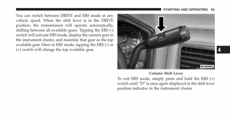
You can switch between DRIVE and ERS mode at anyvehicle speed. When the shift lever is in the DRIVEposition, the transmission will operate automatically,shifting between all available gears. Tapping the ERS (-)switch will activate ERS mode, display the current gear inthe instrument cluster, and maintain that gear as the topavailable gear. Once in ERS mode, tapping the ERS (-) or(+) switch will change the top available gear.
To exit ERS mode, simply press and hold the ERS (+)switch until “D” is once again displayed in the shift leverposition indicator in the instrument cluster.
Column Shift Lever
4
STARTING AND OPERATING 61
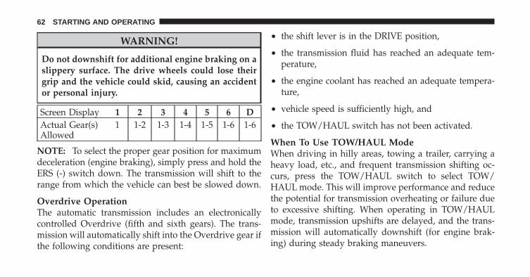
WARNING!
Do not downshift for additional engine braking on aslippery surface. The drive wheels could lose theirgrip and the vehicle could skid, causing an accidentor personal injury.
Screen Display 1 2 3 4 5 6 DActual Gear(s)Allowed
1 1-2 1-3 1-4 1-5 1-6 1-6
NOTE: To select the proper gear position for maximumdeceleration (engine braking), simply press and hold theERS (-) switch down. The transmission will shift to therange from which the vehicle can best be slowed down.
Overdrive OperationThe automatic transmission includes an electronicallycontrolled Overdrive (fifth and sixth gears). The trans-mission will automatically shift into the Overdrive gear ifthe following conditions are present:
• the shift lever is in the DRIVE position,
• the transmission fluid has reached an adequate tem-perature,
• the engine coolant has reached an adequate tempera-ture,
• vehicle speed is sufficiently high, and
• the TOW/HAUL switch has not been activated.
When To Use TOW/HAUL ModeWhen driving in hilly areas, towing a trailer, carrying aheavy load, etc., and frequent transmission shifting oc-curs, press the TOW/HAUL switch to select TOW/HAUL mode. This will improve performance and reducethe potential for transmission overheating or failure dueto excessive shifting. When operating in TOW/HAULmode, transmission upshifts are delayed, and the trans-mission will automatically downshift (for engine brak-ing) during steady braking maneuvers.
62 STARTING AND OPERATING
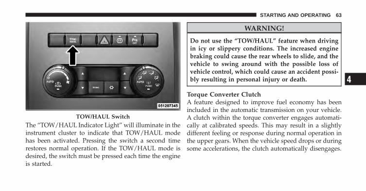
The “TOW/HAUL Indicator Light” will illuminate in theinstrument cluster to indicate that TOW/HAUL modehas been activated. Pressing the switch a second timerestores normal operation. If the TOW/HAUL mode isdesired, the switch must be pressed each time the engineis started.
WARNING!
Do not use the “TOW/HAUL” feature when drivingin icy or slippery conditions. The increased enginebraking could cause the rear wheels to slide, and thevehicle to swing around with the possible loss ofvehicle control, which could cause an accident possi-bly resulting in personal injury or death.
Torque Converter ClutchA feature designed to improve fuel economy has beenincluded in the automatic transmission on your vehicle.A clutch within the torque converter engages automati-cally at calibrated speeds. This may result in a slightlydifferent feeling or response during normal operation inthe upper gears. When the vehicle speed drops or duringsome accelerations, the clutch automatically disengages.
TOW/HAUL Switch
4
STARTING AND OPERATING 63
NOTE:• The torque converter clutch will not engage, and the
transmission will not shift to sixth gear, until thetransmission fluid and engine coolant are warm [usu-ally after 1 to 3 miles (1.6 to 4.8 km) of driving].Because sixth gear is disabled, and engine speed ishigher when the torque converter clutch is not en-gaged, it may seem as if the transmission is notshifting properly when cold. This is normal. Using theElectronic Range Select (ERS) feature, when the trans-mission is sufficiently warm, will demonstrate that thetransmission is able to shift into and out of Overdrive.
• If the vehicle has not been driven for several days, thefirst few seconds of operation after shifting the trans-mission into gear may seem sluggish. This is due to thefluid partially draining from the torque converter intothe transmission. This condition is normal and will notcause damage to the transmission. The torque converterwill refill within five seconds after starting the engine.
Six-Speed Automatic Transmission – If Equipped(Chassis Cab Only)The shift lever position display (located in the instrumentpanel cluster) indicates the transmission gear range. Theshift lever is mounted on the right side of the steeringcolumn. You must press the brake pedal to move the shiftlever out of the PARK position (refer to “Brake/Transmission Shift Interlock System” in this section). Todrive, move the shift lever from PARK or NEUTRAL tothe DRIVE position. Pull the shift lever toward you whenshifting into REVERSE or PARK, or when shifting out ofPARK.
The electronically-controlled transmission provides aprecise shift schedule. The transmission electronics areself-calibrating; therefore, the first few shifts on a newvehicle may be somewhat abrupt. This is a normalcondition, and precision shifts will develop within a fewhundred miles (kilometers).
64 STARTING AND OPERATING
Shifting from DRIVE to PARK or REVERSE should bedone only after the accelerator pedal is released and thevehicle is stopped. Be sure to keep your foot on the brakepedal when moving the shift lever between these gears.
The transmission shift lever has only PARK, REVERSE,NEUTRAL, and DRIVE shift positions. Manual down-shifts can be made using the Electronic Range Select(ERS) shift control (described later). Pressing the ERS(-/+) switches (on the shift lever) while in the DRIVEposition will select the highest available transmissiongear, and will display that gear in the instrument clusteras 6, 5, 4, 3, 2, 1.
Gear RangesDO NOT race the engine when shifting from PARK orNEUTRAL into another gear range.
PARKThis range supplements the parking brake by locking thetransmission. The engine can be started in this range.Never attempt to use PARK while vehicle is in motion.Apply the parking brake when leaving the vehicle in thisrange.
When parking on a level surface, you may place the shiftlever in the PARK position first, and then apply theparking brake.
When parking on a hill, apply the parking brake beforeplacing the shift lever in PARK, otherwise the load on thetransmission locking mechanism may make it difficult tomove the shift lever out of PARK. As an added precau-tion, turn the front wheels toward the curb on a downhillgrade and away from the curb on an uphill grade.
4
STARTING AND OPERATING 65

WARNING!
• Never use the PARK position as a substitute forthe parking brake. Always apply the parkingbrake fully when parked to guard against vehiclemovement and possible injury or damage.
• Your vehicle could move and injure you and othersif it is not completely in PARK. Check by trying tomove the shift lever clockwise without first pull-ing it toward you after you have placed it in PARK.Make sure the transmission is in PARK beforeleaving the vehicle.
(Continued)
WARNING! (Continued)• It is dangerous to move the shift lever out of PARK
or NEUTRAL if the engine speed is higher thanidle speed. If your foot is not firmly pressing onthe brake pedal, the vehicle could acceleratequickly forward or in reverse. You could losecontrol of the vehicle and hit someone or some-thing. Only shift into gear when the engine isidling normally and your foot is firmly pressed onthe brake pedal.
(Continued)
66 STARTING AND OPERATING
WARNING! (Continued)• Unintended movement of a vehicle could injure
those in and near the vehicle. As with all vehicles,you should never exit a vehicle while the engine isrunning. Before exiting a vehicle, always apply theparking brake, shift the transmission into PARK,and remove the key fob. Once the key fob isremoved, the shift lever is locked in the PARKposition, securing the vehicle against unwantedmovement. Furthermore, you should never leaveunattended children inside a vehicle.
• Never leave children alone in a vehicle. Leavingunattended children in a vehicle is dangerous for anumber of reasons. A child or others could beseriously or fatally injured. Do not leave the keyfob in the vehicle. A child could operate powerwindows, other controls, or move the vehicle.
CAUTION!
• Before moving the shift lever out of PARK, youmust turn the ignition switch from the LOCK/OFFposition to the ON/RUN position, and also pressthe brake pedal. Otherwise, damage to the shiftlever could result.
• DO NOT race the engine when shifting fromPARK or NEUTRAL into another gear range, asthis can damage the drivetrain.
The following indicators should be used to ensure thatyou have engaged the shift lever into the PARK position:
• When shifting into PARK, pull the shift lever towardyou and move it all the way counterclockwise until itstops.
• Release the shift lever and make sure it is fully seatedin the PARK gate.
4
STARTING AND OPERATING 67
• Look at the shift lever position display and verify thatit indicates the PARK position.
• With brake pedal released, verify that the shift leverwill not move out of PARK.
REVERSEThis range is for moving the vehicle backward. Shift intoREVERSE only after the vehicle has come to a completestop.
NEUTRALUse this range when the vehicle is standing for prolongedperiods with the engine running. The engine may bestarted in this range. Set the parking brake and shift thetransmission into PARK if you must leave the vehicle.
WARNING!
Do not coast in NEUTRAL and never turn off theignition to coast down a hill. These are unsafepractices that limit your response to changing trafficor road conditions. You might lose control of thevehicle and have an accident.
CAUTION!
Towing the vehicle, coasting, or driving for any otherreason with the transmission in NEUTRAL can resultin severe transmission damage. Refer to “Recre-ational Towing” in “Starting And Operating” and“Towing A Disabled Vehicle” in “What To Do InEmergencies” for further information.
68 STARTING AND OPERATING
DRIVEThis range should be used for most city and highwaydriving. It provides the smoothest upshifts and down-shifts, and the best fuel economy. The transmissionautomatically upshifts through underdrive first, second,and third gears, direct fourth gear and overdrive fifth andsixth gears. The DRIVE position provides optimum driv-ing characteristics under all normal operating conditions.
When frequent transmission shifting occurs (such aswhen operating the vehicle under heavy loading condi-tions, in hilly terrain, traveling into strong head winds, orwhile towing heavy trailers), use the Electronic RangeSelect (ERS) feature (refer to “Electronic Range Select(ERS)” in this section) to select a lower gear range. Underthese conditions, using a lower gear range will improveperformance and extend transmission life by reducingexcessive shifting and heat buildup.
If the transmission operating temperature exceeds nor-mal operating limits, the powertrain controller willmodify the transmission shift schedule and expand therange of torque converter clutch engagement. This isdone to prevent transmission damage due to overheat-ing.
If the transmission becomes extremely hot, the “Trans-mission Temperature Warning Light” may illuminate andthe transmission may downshift out of Overdrive untilthe transmission cools down.
NOTE: Use caution when operating a heavily loadedvehicle at low speeds (such as towing a trailer up a steepgrade, or in stop-and-go traffic) during hot weather. Inthese conditions, torque converter slip can impose asignificant additional heat load on the cooling system.Downshifting the transmission to the lowest possible
4
STARTING AND OPERATING 69
gear (when climbing a grade), or shifting to NEUTRAL(when stopped in heavy traffic) can help to reduce thisexcess heat generation.
During cold temperatures, transmission operation maybe modified depending on engine and transmissiontemperature as well as vehicle speed. This feature im-proves warm up time of the engine and transmission toachieve maximum efficiency. Engagement of the torqueconverter clutch is inhibited until the transmission fluidis warm (refer to the “Note” under “Torque ConverterClutch” in this section). On cold starts below 41°F (5°C),fifth and sixth gears may be inhibited briefly. During verycold temperatures (-4°F [-20°C] or below), operation maybriefly be limited to third gear only. During this condi-tion, the ability of the vehicle to accelerate under heavilyloaded conditions may be reduced. Normal operationwill resume once the transmission temperature has risento a suitable level.
Transmission Limp Home ModeTransmission function is monitored electronically forabnormal conditions. If a condition is detected that couldresult in transmission damage, Transmission Limp HomeMode is activated. In this mode, the transmission remainsin third gear regardless of which forward gear is selected.If the vehicle enters Limp Home Mode at highwayspeeds, it will initially engage fifth gear, until the vehicleslows to a speed where third gear can be engaged. PARK,REVERSE, and NEUTRAL will continue to operate. LimpHome Mode allows the vehicle to be driven to anauthorized dealer for service without damaging thetransmission.
In the event of a momentary problem, the transmissioncan be reset to regain all forward gears by performing thefollowing steps:
1. Stop the vehicle.
70 STARTING AND OPERATING
2. Shift the transmission into PARK.
3. Turn the ignition switch to the LOCK/OFF position.
4. Wait approximately 10 seconds.
5. Restart the engine.
6. Shift into the desired gear range. If the problem is nolonger detected, the transmission will return to normaloperation.
NOTE: Even if the transmission can be reset, we recom-mend that you visit your authorized dealer at yourearliest possible convenience. Your authorized dealer hasdiagnostic equipment to determine if the problem couldrecur.
If the transmission cannot be reset, authorized dealerservice is required.
Electronic Range Select (ERS) OperationThe Electronic Range Select (ERS) shift control allows thedriver to limit the highest available gear when the shiftlever is in the DRIVE position. For example, if you shiftthe transmission into 3 (third gear), the transmission willnever shift above third gear, but will shift down intosecond and first gear normally.
You can switch between DRIVE and ERS mode at anyvehicle speed. When the shift lever is in the DRIVEposition, the transmission will operate automatically,shifting between all available gears. Tapping the ERS (-)switch will activate ERS mode, display the current gear inthe instrument cluster, and maintain that gear as the topavailable gear. Once in ERS mode, tapping the ERS (-) or(+) switch will change the top available gear.
4
STARTING AND OPERATING 71
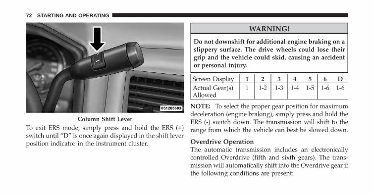
To exit ERS mode, simply press and hold the ERS (+)switch until “D” is once again displayed in the shift leverposition indicator in the instrument cluster.
WARNING!
Do not downshift for additional engine braking on aslippery surface. The drive wheels could lose theirgrip and the vehicle could skid, causing an accidentor personal injury.
Screen Display 1 2 3 4 5 6 DActual Gear(s)Allowed
1 1-2 1-3 1-4 1-5 1-6 1-6
NOTE: To select the proper gear position for maximumdeceleration (engine braking), simply press and hold theERS (-) switch down. The transmission will shift to therange from which the vehicle can best be slowed down.
Overdrive OperationThe automatic transmission includes an electronicallycontrolled Overdrive (fifth and sixth gears). The trans-mission will automatically shift into the Overdrive gear ifthe following conditions are present:
Column Shift Lever
72 STARTING AND OPERATING
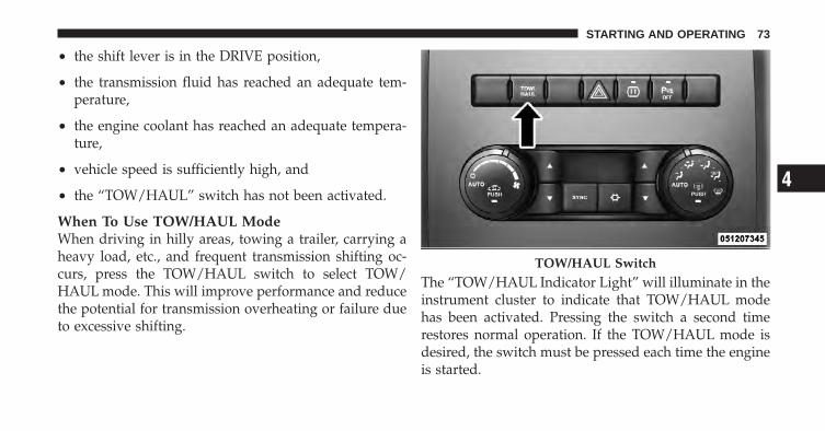
• the shift lever is in the DRIVE position,
• the transmission fluid has reached an adequate tem-perature,
• the engine coolant has reached an adequate tempera-ture,
• vehicle speed is sufficiently high, and
• the “TOW/HAUL” switch has not been activated.
When To Use TOW/HAUL ModeWhen driving in hilly areas, towing a trailer, carrying aheavy load, etc., and frequent transmission shifting oc-curs, press the TOW/HAUL switch to select TOW/HAUL mode. This will improve performance and reducethe potential for transmission overheating or failure dueto excessive shifting.
The “TOW/HAUL Indicator Light” will illuminate in theinstrument cluster to indicate that TOW/HAUL modehas been activated. Pressing the switch a second timerestores normal operation. If the TOW/HAUL mode isdesired, the switch must be pressed each time the engineis started.
TOW/HAUL Switch
4
STARTING AND OPERATING 73
WARNING!
Do not use the “TOW/HAUL” feature when drivingin icy or slippery conditions. The increased enginebraking can cause the rear wheels to slide, and thevehicle to swing around with the possible loss ofvehicle control, which could cause an accident possi-bly resulting in personal injury or death.
Torque Converter ClutchA feature designed to improve fuel economy has beenincluded in the automatic transmission on your vehicle.A clutch within the torque converter engages automati-cally at calibrated speeds. This may result in a slightlydifferent feeling or response during normal operation inthe upper gears. When the vehicle speed drops or duringsome accelerations, the clutch automatically disengages.
NOTE:• The torque converter clutch will not engage until the
transmission fluid and engine coolant are warm [usu-ally after 1 to 3 miles (1.6 to 4.8 km) of driving].Because the engine speed is higher when the torqueconverter clutch is not engaged, it may seem as if thetransmission is not shifting into Overdrive when cold.This is normal. Using the Electronic Range Select (ERS)feature, when the transmission is sufficiently warm,will demonstrate that the transmission is able to shiftinto and out of Overdrive.
• If the vehicle has not been driven for several days, thefirst few seconds of operation after shifting the trans-mission into gear may seem sluggish. This is due to thefluid partially draining from the torque converter intothe transmission. This condition is normal and will notcause damage to the transmission. The torque con-verter will refill within five seconds after starting theengine.
74 STARTING AND OPERATING
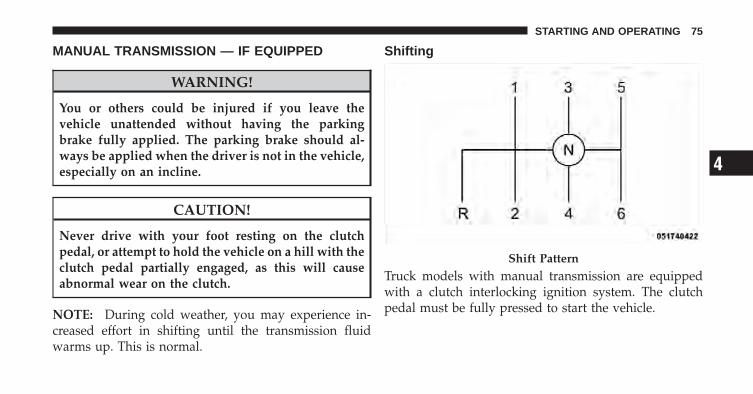
MANUAL TRANSMISSION — IF EQUIPPED
WARNING!
You or others could be injured if you leave thevehicle unattended without having the parkingbrake fully applied. The parking brake should al-ways be applied when the driver is not in the vehicle,especially on an incline.
CAUTION!
Never drive with your foot resting on the clutchpedal, or attempt to hold the vehicle on a hill with theclutch pedal partially engaged, as this will causeabnormal wear on the clutch.
NOTE: During cold weather, you may experience in-creased effort in shifting until the transmission fluidwarms up. This is normal.
Shifting
Truck models with manual transmission are equippedwith a clutch interlocking ignition system. The clutchpedal must be fully pressed to start the vehicle.
Shift Pattern
4
STARTING AND OPERATING 75

Fully press the clutch pedal before shifting gears. As yourelease the clutch pedal, lightly press the acceleratorpedal.
This transmission has a “creeper” first gear which shouldbe used to start from a standing position when carryinga payload or towing a trailer. Damage to the clutch canresult from starting in second or third gear with a loadedvehicle. An unloaded vehicle may be launched in secondgear. Use each gear in numerical order – do not skip agear.
NOTE: When loaded, pulling a trailer or on a grade, thetruck should always start in first gear and not skip gears.
Recommended Vehicle Shift SpeedsTo utilize your manual transmission efficiently for bothfuel economy and performance, it should be upshifted aslisted in recommended shift speed chart. Shift at the
vehicle speeds listed for acceleration. When heavilyloaded or pulling a trailer these recommended up-shiftspeeds may not apply.
Maximum Recommended Up-Shift Speeds
GearSelec-tion
1 to 2 2 to 3 3 to 4 4 to 5 5 to 6
Maxi-mumSpeed
7 mph(11
km/h)
15 mph(24
km/h)
25 mph(40
km/h)
40 mph(64
km/h)
45 mph(72
km/h)
Downshifting
Moving from a high gear down to a lower gear isrecommended to preserve brakes when driving downsteep hills. In addition, downshifting at the right timeprovides better acceleration when you desire to resumespeed. Downshift progressively. Do not skip gears toavoid overspeeding the engine and clutch.
76 STARTING AND OPERATING

WARNING!
Do not downshift for additional engine braking on aslippery surface. The drive wheels could lose theirgrip and the vehicle could skid.
CAUTION!
When descending a hill, be very careful to downshiftone gear at a time to prevent overspeeding the enginewhich can cause valve damage, and/or clutch discdamage even if the clutch pedal is pressed.
Maximum Recommended Downshift Speeds
CAUTION!
Failure to follow the recommended downshiftingspeeds may cause the engine to overspeed and/ordamage the clutch disc even if the clutch pedal ispressed.
Maximum Recommended Downshifting Speeds
GearSelec-tion
6 to 5 5 to 4 4 to 3 3 to 2 2 to 1
Maxi-mumSpeed
68 mph(109
km/h)
50 mph(80
km/h)
32 mph(51
km/h)
19 mph(31
km/h)
10 mph(16
km/h)
4
STARTING AND OPERATING 77
Reverse ShiftingTo shift into REVERSE (R), bring the vehicle to a com-plete stop. Press the clutch and pause briefly to allow thegear train to stop rotating. Beginning from the NEUTRAL(N) position, move the shift lever in one quick smoothmotion straight across and into the REVERSE (R) area(the driver will feel a firm “click” as the shifter passes the“knock-over”). Complete the shift by pulling the shiftlever into REVERSE (R).
The “knock-over” prevents the driver from accidentallyentering the REVERSE (R) shift area and warns the driverthat they are about to shift the transmission into RE-VERSE (R). Due to this feature, a slow shift to REVERSE(R) can be perceived as a high shift effort.
To shift out of REVERSE bring the vehicle to a completestop and press the clutch. Shifting out of REVERSE priorto a complete stop may cause high shift effort.
POWER TAKE OFF OPERATION — IF EQUIPPED(CHASSIS CAB ONLY)This vehicle when equipped with either the AS68RCautomatic six-speed or G-56 manual six-speed transmis-sions, will allow for an aftermarket upfit with a transmis-sion driven PTO (power take off). The customer will havethe ability to operate the PTO in either a “stationary” or“mobile” mode. The vehicles will be factory set to the“stationary” mode. In order to select the “mobile” modean authorized dealership is required to modify the vehi-cle’s settings using their proprietary authorized dealerservice tool.
AS68RC Six-Speed Automatic Transmission OnlyThe PTO drive gear (part of the AS68RC) operates attorque converter turbine speed. The turbine speed will beless than engine speed when the torque converter clutchis not engaged and will be same as engine speed whenthe torque converter clutch is engaged.
78 STARTING AND OPERATING
Stationary Mode
To operate the PTO in this mode the vehicle must meetthe following conditions:
• Be in PARK position (vehicles equipped with auto-matic transmission)
• Upfitter provider (on/off) switch has been activated
• Parking brake applied (vehicles equipped withmanual transmission)
• Brake pedal must not be applied
• Vehicle engine must be running
• No vehicle, brake or clutch switch faults present
• PTO must be correctly installed using the vehicleprovided circuits
The customer has the choice to operate the PTO byutilizing the cruise control switches or by utilizing a
remote control (provided by the PTO supplier). To oper-ate the feature using the cruise control switches, thecustomer must first activate the upfitter-provided on/offswitch which will turn on the PTO. In order to increase ordecrease the engine idle speed, to optimize the PTOfunction, the “RESUME/ACCEL” and “DECEL” cruiseswitches can be used respectively. To disengage PTOoperation and return to “standard vehicle operation”simply turn the upfitter-provided on/off switch to theOFF position.
The torque converter lockup clutch will automaticallyengage at engine speeds above 1,200 RPM (engine speed)in PTO stationary mode. Once engaged, the lockup clutchwill remain on and not disengage until the engine speedis below 1,000 RPM. Lockup clutch engagement is desir-able for certain types of PTO applications (AS68RCSix-Speed Automatic Transmission Only).
4
STARTING AND OPERATING 79
To operate the PTO via a remote switch, the customermust make sure the above conditions are met. It is vitalfor proper operation that the PTO and remote have beeninstalled correctly, paying special attention to ensure thevehicle provided wiring has been connected properly.This is the responsibility of the installer of the PTO andswitches/remote system. It is the responsibility of thePTO manufacturer to ensure that their electrical (switchesand remote) system is compatible with the vehicle’selectrical architecture and software functionality.
NOTE: If you desire a single PTO speed, your vehiclemust be wired to use a remote PTO switch. For instruc-tions on programming the SET speed, refer to theLEARNING SET SPEED section of the Body Builder’sGuide which can be found at www.ramtrucks.com.
Mobile Mode
To operate the PTO in this mode the vehicle must meetthe following conditions:
• Authorized dealer-selected “mobile” mode activatedvia authorized dealer proprietary service tool
• Upfitter-provided (on/off) switch has been activated
• Vehicle must be in PARK or DRIVE position (vehiclesequipped with automatic transmission)
• Parking brake must not be applied
• Brake pedal must not be applied
• No vehicle, brake or clutch switch faults present
• Vehicle engine must be running
• PTO must be correctly installed using the vehicleprovided circuits
The customer may choose to use the PTO while thevehicle is moving. To do so, the PTO function must beactivated prior to taking the vehicle out of PARK. This isaccomplished by activating the upfitter-provided PTO
80 STARTING AND OPERATING
on/off switch. At this point, the customer may place thevehicle in a forward or reverse gear and have PTOoperation once the vehicle begins to move. To disengagePTO operation and return to “standard vehicle opera-tion” simply turn the upfitter-provided on/off switch tothe OFF position.
NOTE: For application specific information with respectto PTO and pump requirements and additional vehicleinformation (wiring schematics, preset idle values, en-gine speed limits, and vehicle hardware and softwarerequirements) please refer to the Body Builders Guide byaccessing www.ramtrucks.com and choosing the appro-priate links.
Power Take Off – Aftermarket InstallationIf you did not order the PTO (Power Take Off) PrepPackage from the factory and want to convert your
vehicle, refer to the Body Builder’s Guide atwww.ramtrucks.com or contact the manufacturer di-rectly at (866) 205–4102 (toll free).
ENGINE RUNAWAY
WARNING!
In case of engine runaway due to flammable fumesfrom gasoline spills or turbocharger oil leaks beingsucked into the engine, do the following to helpavoid personal injury and/or vehicle damage:1. Turn the ignition switch to the OFF position.2. Using a CO2 or dry chemical type fire extin-guisher, direct the spray from the fire extinguisherinto the grille on the passenger side so that the sprayenters the engine air intake.
(Continued)
4
STARTING AND OPERATING 81
WARNING! (Continued)The inlet for the engine air intake is located behindthe passenger side headlamp and receives airthrough the grille.
FUEL REQUIREMENTSUse good quality diesel fuel from a reputable supplier inyour vehicle. Federal law requires that you must fuel thisvehicle with Ultra Low Sulfur Highway Diesel fuel (15ppm Sulfur maximum) and prohibits the use of LowSulfur Highway Diesel fuel (500 ppm Sulfur maximum)to avoid damage to the emissions control system. Formost year-round service, No. 2 diesel fuel meeting ASTMspecification D-975 Grade S15 will provide good perfor-mance. If the vehicle is exposed to extreme cold (below20°F or -7°C), or is required to operate at colder-than-normal conditions for prolonged periods, use climatizedNo. 2 diesel fuel or dilute the No. 2 diesel fuel with 50%
No. 1 diesel fuel. This will provide better protection fromfuel gelling or wax-plugging of the fuel filters.
WARNING!
Do not use alcohol or gasoline as a fuel blendingagent. They can be unstable under certain conditionsand hazardous or explosive when mixed with dieselfuel.
Diesel fuel is seldom completely free of water. To preventfuel system trouble, drain the accumulated water fromthe fuel/water separator using the fuel/water separatordrain provided. If you buy good quality fuel and followthe cold weather advice above, fuel conditioners shouldnot be required in your vehicle. If available in your area,a high cetane “premium” diesel fuel may offer improvedcold-starting and warm-up performance.
82 STARTING AND OPERATING
Fuel SpecificationsThe Cummins� diesel engine has been developed to takeadvantage of the high energy content and generallylower cost No. 2 Ultra Low Sulfur diesel fuel or No. 2Ultra Low Sulfur climatized diesel fuels. Experience hasshown that it also operates on No. 1 Ultra Low Sulfurdiesel fuels or other fuels within specification.
NOTE:• A maximum blend of 5% biodiesel meeting ASTM
specification D-6751 may be used with your Cum-mins� diesel engine.
• In addition, commercially available fuel additives arenot necessary for the proper operation of your Cum-mins� diesel engine.
• No. 1 Ultra Low Sulfur diesel fuel should only be usedwhere extended arctic conditions (-10°F or -23°C) exist.
ADDING FUEL
CAUTION!
To avoid fuel spillage and overfilling, do not “topoff” the fuel tank after filling.
NOTE:• When the fuel nozzle “clicks” or shuts off, the fuel
tank is full.
• Tighten the fuel filler cap until you hear a “clicking”sound. This is an indication that the fuel filler cap isproperly tightened.
• Make sure that the fuel filler cap is tightened each timethe vehicle is refueled.
4
STARTING AND OPERATING 83
WARNING!
A fire may result if fuel is pumped into a portablecontainer that is on a truck bed. You could be burned.Always place fuel containers on the ground whilefilling.
Fuel Filler Cap
If the fuel filler cap is lost or damaged, be sure thereplacement cap is for use with this vehicle.
CAUTION!
Damage to the fuel system or emission control sys-tem could result from using an improper fuel tankfiller tube cap. A poorly fitting cap could let impuri-ties into the fuel system.
WARNING!
• Never have any smoking materials lit in or nearthe vehicle when the fuel filler cap is removed orthe tank filled.
• Never add fuel to the vehicle when the engine isrunning.
Avoid Using Contaminated FuelFuel that is contaminated by water or dirt can causesevere damage to the engine fuel system. Proper main-tenance of the engine fuel filter and fuel tank is essential.Refer to “Maintenance Procedures” in “Maintaining YourVehicle” for further information.
Bulk Fuel Storage – Diesel FuelIf you store quantities of fuel, good maintenance of thestored fuel is also essential. Fuel contaminated withwater will promote the growth of “microbes.” These
84 STARTING AND OPERATING
microbes form “slime” that will clog fuel filters and lines.Drain condensation from the supply tank and change theline filter on a regular basis.
NOTE: When a diesel engine is allowed to run out offuel, air is pulled into the fuel system.
If the vehicle will not start, refer to “MaintenanceProcedures/Priming If The Engine Has Run Out Of Fuel”in “Maintaining Your Vehicle” for further information.
WARNING!
Do not open the high pressure fuel system with theengine running. Engine operation causes high fuelpressure. High pressure fuel spray can cause seriousinjury or death.
Diesel Exhaust Fluid StorageDiesel Exhaust Fluid (DEF) is considered a very stableproduct with a long shelf life. If DEF is kept in tempera-tures between 10° to 90°F (-12° to 32°C), it will last aminimum of one year.
DEF is subject to freezing at the lowest temperatures. Forexample, DEF may freeze at temperatures at or below12° F (-11° C). The system has been designed to operate inthis environment.
NOTE: When working with DEF, it is important toknow that:
• Any containers or parts that come into contact withDEF must be DEF compatible (plastic or stainlesssteel). Copper, brass, aluminum, iron or non-stainlesssteel should be avoided as they are subject to corrosionby DEF.
• If DEF is spilled, it should be wiped up completely
4
STARTING AND OPERATING 85
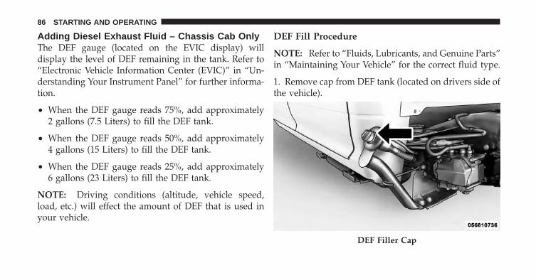
Adding Diesel Exhaust Fluid – Chassis Cab OnlyThe DEF gauge (located on the EVIC display) willdisplay the level of DEF remaining in the tank. Refer to“Electronic Vehicle Information Center (EVIC)” in “Un-derstanding Your Instrument Panel” for further informa-tion.
• When the DEF gauge reads 75%, add approximately2 gallons (7.5 Liters) to fill the DEF tank.
• When the DEF gauge reads 50%, add approximately4 gallons (15 Liters) to fill the DEF tank.
• When the DEF gauge reads 25%, add approximately6 gallons (23 Liters) to fill the DEF tank.
NOTE: Driving conditions (altitude, vehicle speed,load, etc.) will effect the amount of DEF that is used inyour vehicle.
DEF Fill Procedure
NOTE: Refer to “Fluids, Lubricants, and Genuine Parts”in “Maintaining Your Vehicle” for the correct fluid type.
1. Remove cap from DEF tank (located on drivers side ofthe vehicle).
DEF Filler Cap
86 STARTING AND OPERATING

2. Insert DEF fill adapter/nozzle into DEF tank fillerneck.
CAUTION!
• To avoid DEF spillage, and possible damage to theDEF tank from overfilling, do not “top off” theDEF tank after filling.
• When DEF is spilled, clean the area immediatelywith water or use an absorbent material to soak upand spills on the ground.
3. Stop filling the DEF tank immediately when any of thefollowing happen: DEF stops flowing from the fill bottleinto the DEF tank, DEF splashes out the filler neck, or aDEF pump nozzle automatically shuts off.
4. Reinstall cap onto DEF tank.Filling the DEF Tank
4
STARTING AND OPERATING 87
DIESEL EXHAUST FLUID — CHASSIS CAB ONLYYour vehicle is equipped with a Selective Catalytic Re-duction system in order to meet the very stringent dieselemissions standards required by the Environmental Pro-tection Agency. Selective Catalytic Reduction (SCR) is thefirst and only technology in decades to be as good for theenvironment as it is good for business and vehicleperformance.
The purpose of the SCR system is to reduce levels of NOx(oxides of nitrogen emitted from engines) that are harm-ful to our health and the environment to an almostnear-zero level. Small quantities of Diesel Exhaust Fluid(DEF) are injected into the exhaust upstream of a catalystwhere, when vaporized, convert smog-forming nitrogenoxides (NOx) into harmless nitrogen (N2) and watervapor (H2O), two natural components of the air webreathe. You can operate with the comfort that yourvehicle is contributing to a cleaner, healthier worldenvironment for this and generations to come.
System OverviewThis vehicle is equipped with a Diesel Exhaust Fluid(DEF) injection system and a Selective Catalytic Reduc-tion (SCR) catalyst to meet the emission requirements.
The DEF injection system consists of the following com-ponents:
• DEF tank
• DEF pump
• DEF injector
• Electronically-heated DEF lines
• DEF control module
• NOx sensors
• Temperature sensors
• SCR catalyst
88 STARTING AND OPERATING
The DEF injection system and SCR catalyst enable theachievement of diesel emissions requirements; whilemaintaining outstanding fuel economy, drivability,torque and power ratings.
Refer to “Electronic Vehicle Information Center(EVIC)” in “Understanding Your Instrument Panel” forsystem messages and warnings.
NOTE: The DEF pump will run for a period of timeafter engine shutdown to purge the DEF system. This isnormal operation.
4
STARTING AND OPERATING 89

WHAT TO DO IN EMERGENCIES
CONTENTS
� Jump Starting . . . . . . . . . . . . . . . . . . . . . . . . . 92 ▫ With Portable Starting Unit . . . . . . . . . . . . . . 95
5
JUMP STARTING
WARNING!
• To prevent personal injury or damage to clothing,do not allow battery fluid to contact eyes, skin orfabrics. Do not lean over a battery when connect-ing jumper cables or allow cable clamps to toucheach other. Keep open flames or sparks away frombattery vent holes. Always wear eye protectionwhen working with batteries.
• Do not use a booster battery or any other boostersource that has a greater than 12 Volt system, i.e.,do not use a 24 Volt power source.
NOTE: Replacement batteries should both be of equalsize to prevent damage to the vehicle’s charging system.
Your vehicle is equipped with two 12 Volt batteries. If itbecomes necessary to use a booster battery with jumper
cables to start a vehicle’s engine because its batteries aredischarged, the following procedure should be used:
Set the parking brake and place an automatic transmis-sion in PARK (or NEUTRAL for a manual transmission).Turn off lights, heater and other electrical loads. Observecharge indicator (if equipped) in both batteries. If theindicator (if equipped) is light or yellow on either battery,replace that battery.
CAUTION!
Use the jump start procedure only when the chargeindicator (if equipped) in both batteries is dark in thecenter. Do not attempt jump starting when eitherbattery charge indicator (if equipped) is bright oryellow. If the charge indicator (if equipped) has agreen dot in the center, failure to start is not due to adischarged battery and cranking system should bechecked.
92 WHAT TO DO IN EMERGENCIES
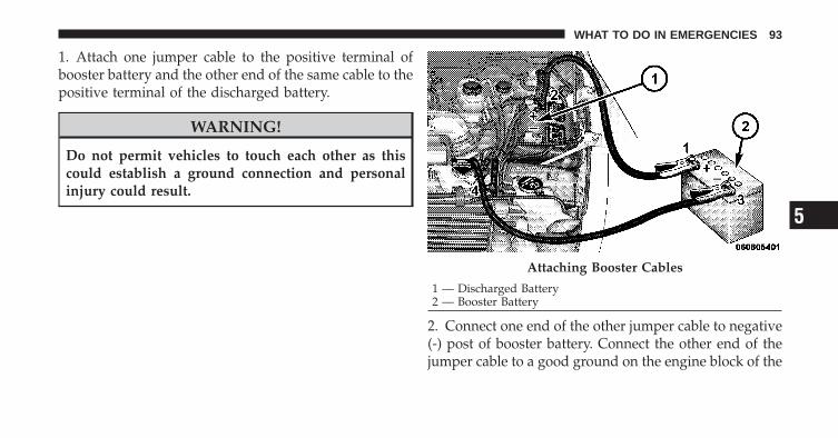
1. Attach one jumper cable to the positive terminal ofbooster battery and the other end of the same cable to thepositive terminal of the discharged battery.
WARNING!
Do not permit vehicles to touch each other as thiscould establish a ground connection and personalinjury could result.
2. Connect one end of the other jumper cable to negative(-) post of booster battery. Connect the other end of thejumper cable to a good ground on the engine block of the
Attaching Booster Cables
1 — Discharged Battery2 — Booster Battery
5
WHAT TO DO IN EMERGENCIES 93
vehicle with the discharged battery. Make sure a goodconnection is made, free of dirt and grease.
WARNING!
• Do not connect the cable to the negative post of thedischarge battery. The resulting electrical sparkcould cause the battery to explode.
• During cold weather when temperatures are be-low freezing point, electrolyte in a dischargedbattery may freeze. Do not attempt jump startingbecause the battery could rupture or explode. Thebattery temperature must be brought up abovefreezing point before attempting to jump start.
3. Take care that the clamps from one cable do notinadvertently touch clamps from the other cable. Do notlean over the battery when making connection. Thenegative connection must provide good electrical con-ductivity and current carrying capacity.
4. After the engine is started or if the engine fails to start,cables must be disconnected in the following order:
a. Disconnect the negative cable at the engine ground.
b. Disconnect the negative cable at the negative poston booster battery.
c. Disconnect the cable from the positive post of bothbatteries.
WARNING!
Any procedure other than above could result in:• Personal injury caused by electrolyte squirting out
the battery vent;• Personal injury or property damage due to battery
explosion;• Damage to charging system of booster vehicle or
of immobilized vehicle.
94 WHAT TO DO IN EMERGENCIES
With Portable Starting UnitThere are many types of these units available. Follow themanufacturer’s instructions for necessary precautionsand operation.
CAUTION!
It is very important that the starting unit operatingvoltage does not exceed 12 Volts DC or damage tobattery, starter motor, alternator, or electrical systemmay occur. 5
WHAT TO DO IN EMERGENCIES 95

MAINTAINING YOUR VEHICLE
CONTENTS
� Engine Compartment — 6.7L Diesel . . . . . . . . . 99
� Maintenance Procedures . . . . . . . . . . . . . . . . . 100
▫ Engine Oil . . . . . . . . . . . . . . . . . . . . . . . . . 100
▫ Engine Air Cleaner Filter . . . . . . . . . . . . . . . 104
▫ Draining Fuel/Water Separator Filter . . . . . . 106
▫ Fuel Filter Replacement . . . . . . . . . . . . . . . . 108
▫ Priming If The Engine Has Run Out OfFuel . . . . . . . . . . . . . . . . . . . . . . . . . . . . . . 110
▫ Intervention Regeneration Strategy – EVICMessage Process Flow . . . . . . . . . . . . . . . . . . 111
▫ Diesel Exhaust Fluid – Chassis Cab Only . . . 114
▫ Maintenance-Free Batteries . . . . . . . . . . . . . 114
▫ Cooling System . . . . . . . . . . . . . . . . . . . . . 115
▫ Charge Air Cooler – Inter-Cooler . . . . . . . . . 121
▫ Brake System . . . . . . . . . . . . . . . . . . . . . . . 121
▫ Clutch Hydraulic System . . . . . . . . . . . . . . . 123
▫ Transfer Case – If Equipped . . . . . . . . . . . . . 123
▫ Manual Transmission – If Equipped . . . . . . . 124
▫ Automatic Transmission – If Equipped . . . . . 124
6
▫ Noise Control System Required Maintenance& Warranty . . . . . . . . . . . . . . . . . . . . . . . . 128
� Fluid Capacities . . . . . . . . . . . . . . . . . . . . . . 133
� Fluids, Lubricants And Genuine Parts . . . . . . . 134
▫ Engine . . . . . . . . . . . . . . . . . . . . . . . . . . . . 134
▫ Chassis . . . . . . . . . . . . . . . . . . . . . . . . . . . 136
98 MAINTAINING YOUR VEHICLE
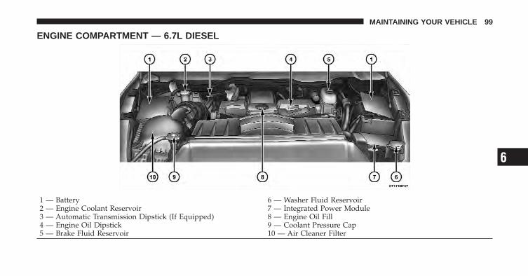
ENGINE COMPARTMENT — 6.7L DIESEL
1 — Battery 6 — Washer Fluid Reservoir2 — Engine Coolant Reservoir 7 — Integrated Power Module3 — Automatic Transmission Dipstick (If Equipped) 8 — Engine Oil Fill4 — Engine Oil Dipstick 9 — Coolant Pressure Cap5 — Brake Fluid Reservoir 10 — Air Cleaner Filter
6
MAINTAINING YOUR VEHICLE 99
MAINTENANCE PROCEDURESThe pages that follow contain the required maintenanceservices determined by the engineers who designed yourvehicle.
Besides those maintenance items specified in the fixedmaintenance schedule, there are other components whichmay require servicing or replacement in the future.
CAUTION!
• Failure to properly maintain your vehicle or per-form repairs and service when necessary couldresult in more costly repairs, damage to othercomponents or negatively impact vehicle perfor-mance. Immediately have potential malfunctionsexamined by an authorized Chrysler Group LLCdealership or qualified repair center.
(Continued)
CAUTION! (Continued)• Your vehicle has been built with improved fluids
that protect the performance and durability ofyour vehicle and also allow extended maintenanceintervals. Do not use chemical flushes in thesecomponents as the chemicals can damage yourengine, transmission, power steering or air condi-tioning. Such damage is not covered by the NewVehicle Limited Warranty. If a flush is neededbecause of component malfunction, use only thespecified fluid for the flushing procedure.
Engine Oil
Checking Oil LevelTo assure proper lubrication of your vehicle’s engine, theengine oil must be maintained at the correct level. Checkthe oil level at regular intervals. The best time to checkthe oil level is before starting the engine after it has been
100 MAINTAINING YOUR VEHICLE
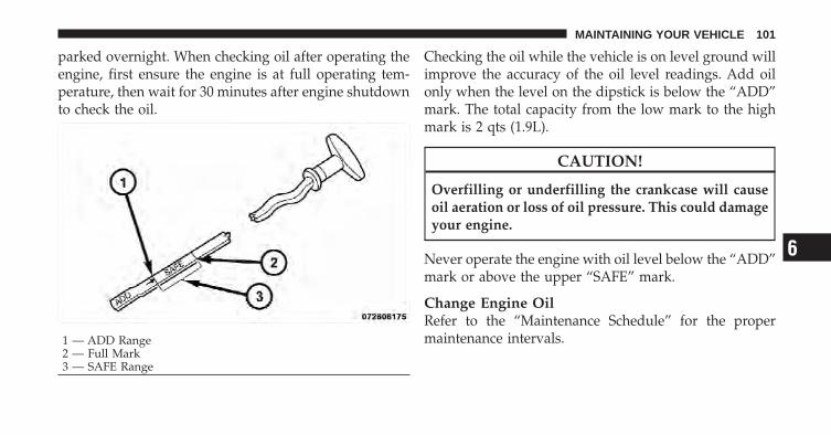
parked overnight. When checking oil after operating theengine, first ensure the engine is at full operating tem-perature, then wait for 30 minutes after engine shutdownto check the oil.
Checking the oil while the vehicle is on level ground willimprove the accuracy of the oil level readings. Add oilonly when the level on the dipstick is below the “ADD”mark. The total capacity from the low mark to the highmark is 2 qts (1.9L).
CAUTION!
Overfilling or underfilling the crankcase will causeoil aeration or loss of oil pressure. This could damageyour engine.
Never operate the engine with oil level below the “ADD”mark or above the upper “SAFE” mark.
Change Engine OilRefer to the “Maintenance Schedule” for the propermaintenance intervals.1 — ADD Range
2 — Full Mark3 — SAFE Range
6
MAINTAINING YOUR VEHICLE 101
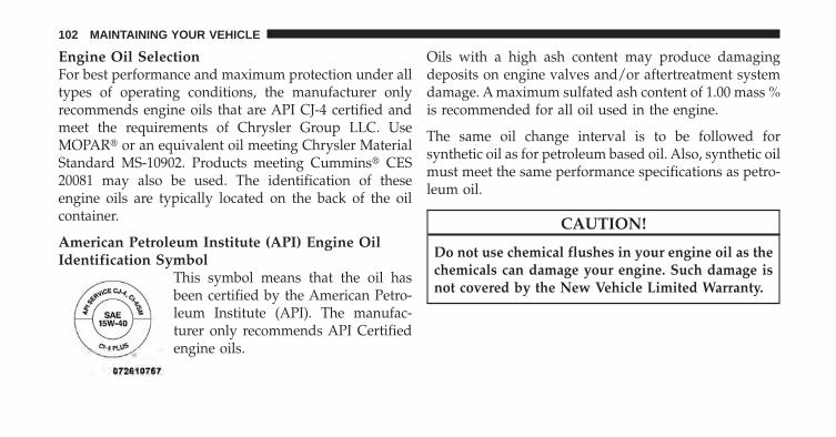
Engine Oil SelectionFor best performance and maximum protection under alltypes of operating conditions, the manufacturer onlyrecommends engine oils that are API CJ-4 certified andmeet the requirements of Chrysler Group LLC. UseMOPAR� or an equivalent oil meeting Chrysler MaterialStandard MS-10902. Products meeting Cummins� CES20081 may also be used. The identification of theseengine oils are typically located on the back of the oilcontainer.
American Petroleum Institute (API) Engine OilIdentification Symbol
This symbol means that the oil hasbeen certified by the American Petro-leum Institute (API). The manufac-turer only recommends API Certifiedengine oils.
Oils with a high ash content may produce damagingdeposits on engine valves and/or aftertreatment systemdamage. A maximum sulfated ash content of 1.00 mass %is recommended for all oil used in the engine.
The same oil change interval is to be followed forsynthetic oil as for petroleum based oil. Also, synthetic oilmust meet the same performance specifications as petro-leum oil.
CAUTION!
Do not use chemical flushes in your engine oil as thechemicals can damage your engine. Such damage isnot covered by the New Vehicle Limited Warranty.
102 MAINTAINING YOUR VEHICLE
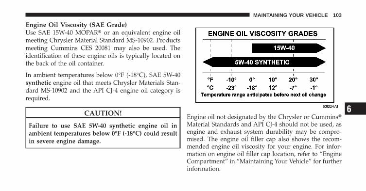
Engine Oil Viscosity (SAE Grade)Use SAE 15W-40 MOPAR� or an equivalent engine oilmeeting Chrysler Material Standard MS-10902. Productsmeeting Cummins CES 20081 may also be used. Theidentification of these engine oils is typically located onthe back of the oil container.
In ambient temperatures below 0°F (-18°C), SAE 5W-40synthetic engine oil that meets Chrysler Materials Stan-dard MS-10902 and the API CJ-4 engine oil category isrequired.
CAUTION!
Failure to use SAE 5W-40 synthetic engine oil inambient temperatures below 0°F (-18°C) could resultin severe engine damage.
Engine oil not designated by the Chrysler or Cummins�Material Standards and API CJ-4 should not be used, asengine and exhaust system durability may be compro-mised. The engine oil filler cap also shows the recom-mended engine oil viscosity for your engine. For infor-mation on engine oil filler cap location, refer to “EngineCompartment” in “Maintaining Your Vehicle” for furtherinformation.
6
MAINTAINING YOUR VEHICLE 103
Synthetic Engine OilsYou may use synthetic engine oils provided the recom-mended oil quality requirements are met, and the recom-mended maintenance intervals for oil and filter changesare followed.
Materials Added To Engine OilThe manufacturer strongly recommends against the ad-dition of any additives (other than leak detection dyes orlube odorants) to the engine oil. Engine oil is an engi-neered product and its performance may be impaired bysupplemental additives.
Engine Oil FilterRefer to “Fluids, Lubricants, and Genuine Parts” in“Maintaining Your Vehicle” for further information. Theengine oil filter should be changed at every engine oilchange.
Disposing Of Used Engine Oil And FilterCare should be taken in disposing of the used enginefluids from your vehicle. Used fluids, indiscriminatelydiscarded, can present a problem to the environment.Contact an authorized dealer, service station, or govern-mental agency for advice on recycling programs andwhere used fluids and filters can be safely discarded inyour area.
Engine Air Cleaner Filter
CAUTION!
All air entering the engine intake must be filtered.The abrasive particles in unfiltered air will causerapid wear to engine components.
104 MAINTAINING YOUR VEHICLE

The condition of the air cleaner filter is monitored by theEngine Control Module. The “SERVICE AIR FILTER”message will display in the Electronic Vehicle Informa-tion Center (EVIC) when service is required. Refer to“Electronic Vehicle Information Center (EVIC)” in “Un-derstanding Your Instrument Panel” for further informa-tion.
Do not remove the top of the air filter housing toinspect the filter element on your diesel engine undernormal operating conditions.
The “SERVICE AIR FILTER” message could be displayedperiodically. This is because engine air flow requirementschange based on driving conditions. As the filter becomesmore restrictive and air flow requirements increase the“SERVICE AIR FILTER” message will be displayed. Themessage may not be displayed in subsequent drive cyclesif the same conditions are not met. The air filter elementshould be replaced within 250 miles (402 km) from the
first time this message is displayed to ensure properengine operation during all driving conditions.
CAUTION!
Driving with a restricted air filter can cause enginedamage. Driving in dusty environments for extendedperiods will lead to rapid air filter plugging. Actionshould be taken as soon as the “SERVICE AIRFILTER” message is displayed.
If the vehicle experiences a sudden loss of engine powerwhile being driven in heavy snow or rain, or whenplowing snow, and/or the “SERVICE AIR FILTER” mes-sage is displayed on the EVIC along with a chime thatrepeats every 60 seconds, visually inspect the air filter forsnow/ice build up or extreme water saturation. If the airfilter is not damaged, remove all snow/ice and reinstallair filter. If the air filter is damaged, replace filter element.
6
MAINTAINING YOUR VEHICLE 105
NOTE: The air filter housing contains a Mass Air Flowsensor. This sensor is critical to proper engine operationand component longevity. Any damage or modificationto this sensor could result in major engine and/orexhaust aftertreatment damage. This includes the use ofnon-approved air filters. Use only MOPAR� approved airfilters or equivalent.
A visual inspection of the air cleaner filter element isnever recommended under normal circumstances. Abadly restricted element may appear clean while a soiledelement may be quite effective in filtering particleswithout restricting air flow. Rely on the Engine ControlModule to determine when a filter change is necessary.
CAUTION!
Many aftermarket performance air filter elements donot adequately filter the air entering the engine. Useof such filters can severely damage your engine.
Draining Fuel/Water Separator FilterThe fuel filter and water separator assembly is located onthe driver’s side of the engine. The best access to thewater drain valve is from under the hood.
CAUTION!
• Do not drain the fuel/water separator filter whenthe engine is running.
• Diesel fuel will damage blacktop paving surfaces.Drain the filter into an appropriate container.
If water is detected in the water separator while theengine is running, or while the ignition switch is in theON position, the “Water In Fuel Indicator Light” willilluminate and an audible chime will be heard five times.At this point you should stop the engine and drain thewater from the separator.
106 MAINTAINING YOUR VEHICLE

CAUTION!
If the “Water In Fuel Indicator Light” remains on, DONOT START the engine before you drain water fromthe fuel filter to avoid engine damage.
If the “Water In Fuel Indicator Light” comes on and asingle chime is heard while you are driving, or with theignition switch in the ON position, there may be aproblem with your water separator wiring or sensor. Seeyour authorized dealer for service.
Upon proper draining of the water from the fuel filter, the“Water In Fuel Indicator Light” will remain illuminatedfor approximately 10 seconds. If the water was drainedwhile the engine was running, the “Water In Fuel Indi-cator Light” may remain on for approximately threeminutes.
NOTE: Care should be taken in disposing of used fluidsfrom your vehicle. Used fluids, indiscriminately dis-carded, can present a problem to the environment. Con-tact an authorized dealer, service station, or governmentagency for advice on recycling programs and for whereused fluids and filters can be properly disposed of inyour area.
Drain the fuel/water separator filter when the “Water InFuel Indicator Light” is ON. Within 10 minutes of vehicleshutdown, turn the drain valve (located on the side of thefilter) counterclockwise 1/4 turn, turn the ignition switchto the ON position, and allow any accumulated water todrain. Leave the drain valve open until all water andcontaminants have been removed. When clean fuel isvisible, close the drain valve by turning it clockwise, andturn the ignition switch to OFF.
6
MAINTAINING YOUR VEHICLE 107
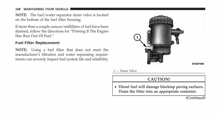
NOTE: The fuel/water separator drain valve is locatedon the bottom of the fuel filter housing.
If more than a couple ounces/milliliters of fuel have beendrained, follow the directions for “Priming If The EngineHas Run Out Of Fuel.”
Fuel Filter Replacement
NOTE: Using a fuel filter that does not meet themanufacturer’s filtration and water separating require-ments can severely impact fuel system life and reliability.
CAUTION!
• Diesel fuel will damage blacktop paving surfaces.Drain the filter into an appropriate container.
(Continued)
1 — Drain Valve
108 MAINTAINING YOUR VEHICLE
CAUTION! (Continued)• Do not prefill the fuel filter when installing a new
fuel filter. There is a possibility debris could beintroduced into the fuel filter during this action. Itis best to install the filter dry and allow the in-tanklift pump to prime the fuel system.
1. Ensure engine is turned off.
2. Place drain pan under the fuel filter drain hose.
3. Open the water drain valve 1/4 turn counterclockwiseand completely drain fuel and water into the approvedcontainer.
4. Close the water drain valve.
5. Remove lid using a socket or strap wrench. Rotatecounterclockwise for removal. Remove used o-ring anddiscard it.
6. Remove the used filter cartridge from the housing anddispose of according to your local regulations.
7. Wipe clean the sealing surfaces of the lid and housing.
8. Install new o-ring back into ring groove on the filterhousing and lubricate with clean engine oil.
9. Remove new filter cartridge from plastic bag andinstall into housing.
NOTE: Do not remove cartridge from bag until youreach this step in order to keep cartridge clean.
10. Push down on the cartridge to ensure it is properlyseated. Do not pre-fill the filter housing with fuel.
11. Install lid onto housing and tighten to 22.5 ft lbs(30.5 N.m). Do not overtighten the lid.
12. Prime the engine using the procedure in “Priming IfThe Engine Has Run Out Of Fuel.” Then start the engineand confirm there are no leaks.
6
MAINTAINING YOUR VEHICLE 109
Priming If The Engine Has Run Out Of Fuel
WARNING!
Do not open the high pressure fuel system with theengine running. Engine operation causes high fuelpressure. High pressure fuel spray can cause seriousinjury or death.
1. Add a substantial amount of fuel to the tank, approxi-mately 5 to 10 gal (19L to 38L).
2. Turn the ignition switch to the RUN position, wait forfour seconds, then turn the ignition switch back to theOFF position. Repeat this step four times.
3. Start the engine using the “Normal Starting” proce-dure. Refer to “Starting Procedures” in “Starting andOperating” for further information.
CAUTION!
Do not engage the starter motor for more than 15 sec-onds at a time. Allow two minutes between thecranking intervals.
NOTE: The engine may run rough until the air is forcedfrom all the fuel lines.
WARNING!
Do not use alcohol or gasoline as a fuel blendingagent. They can be unstable under certain conditionsand be hazardous or explosive when mixed withdiesel fuel.
110 MAINTAINING YOUR VEHICLE
CAUTION!
Due to lack of lubricants in alcohol or gasoline, theuse of these fuels can cause damage to the fuelsystem.
NOTE:• A maximum blend of 5% biodiesel, meeting ASTM
specification D-6751 may be used with your Cum-mins� diesel engine. Use of biodiesel mixture in excessof 5% can negatively impact the fuel filter’s ability toseparate water from the fuel, resulting in high pressurefuel system corrosion or damage.
• Ethanol blends are not recommended or approved foruse with your Cummins� diesel engine.
• In addition, commercially available fuel additives arenot necessary for the proper operation of your Cum-mins� diesel engine.
Intervention Regeneration Strategy – EVICMessage Process FlowThe Cummins� diesel engine meets all EPA Heavy DutyDiesel Engine Emissions Standards, resulting in the low-est emitting diesel engine ever produced.
To achieve these emissions standards, your vehicle isequipped with a state-of-the-art engine and exhaustsystem. The engine and exhaust after-treatment systemwork together to achieve the EPA Heavy Duty DieselEngine Emissions Standards. These systems are seam-lessly integrated into your vehicle and managed by theCummins� Powertrain Control Module (PCM). The PCMmanages engine combustion to allow the exhaust sys-tem’s catalyst to trap and burn Particulate Matter (PM)pollutants, with no input or interaction on your part.
Additionally, your vehicle has the ability to alert you toadditional maintenance required on your truck or engine.
6
MAINTAINING YOUR VEHICLE 111
Refer to the following messages that may be displayed onyour Electronic Vehicle Information Center (EVIC):
WARNING!
A hot exhaust system can start a fire if you park overmaterials that can burn. Such materials might begrass or leaves coming into contact with your exhaustsystem. Do not park or operate your vehicle in areaswhere your exhaust system can contact anything thatcan burn.
Perform ServiceYour vehicle will require emissions maintenance at a setinterval. To help remind you when this maintenance isdue, the Electronic Vehicle Information Center (EVIC)will display “Perform Service”. When the “Perform Ser-vice” message is displayed on the EVIC it is necessary tohave the emissions maintenance performed. Emissions
maintenance may include replacing the Closed Crank-case Ventilation (CCV) filter element, and cleaning of theEGR Cooler. The procedure for clearing and resetting the�Perform Service� indicator message is located in theappropriate Service Information.
Exhaust System – Regeneration Required Now“Exhaust System — Regeneration Required Now” will bedisplayed on the Electronic Vehicle Information Center(EVIC) if the exhaust particulate filter reaches 80% of itsmaximum storage capacity. Under conditions of exclu-sive short duration and low speed driving cycles, yourCummins� diesel engine and exhaust after-treatmentsystem may never reach the conditions required to re-move the trapped PM. If this occurs, the “Exhaust System— Regeneration Required Now” message will be dis-played in the EVIC. If this message is displayed, you willhear one chime to assist in alerting you of this condition.
112 MAINTAINING YOUR VEHICLE
By simply driving your vehicle at highway speeds for aslittle as 45 minutes, you can remedy the condition in theparticulate filter system and allow your Cummins� dieselengine and exhaust after-treatment system to remove thetrapped PM and restore the system to normal operatingcondition.
Exhaust Filter XX% FullIndicates that the Diesel Particulate Filter (DPF) is ap-proaching full.
Exhaust System – Regeneration In ProcessIndicates that the Diesel Particulate Filter (DPF) is self-cleaning. Maintain your current driving condition untilregeneration is completed.
Exhaust System – Regeneration CompletedIndicates that the Diesel Particulate Filter (DPF) self-cleaning is completed. If this message is displayed, youwill hear one chime to assist in alerting you of thiscondition.
Exhaust Service Required - See Dealer NowRegeneration has been disabled due to a system malfunc-tion. At this point the engine PCM will register a faultcode, the instrument panel will display a MIL light.
CAUTION!
See your authorized dealer, as damage to the exhaustsystem could occur soon with continued operation.
Exhaust Filter Full – Power Reduced See DealerThe PCM derates the engine in order to limit the likeli-hood of permanent damage to the after-treatment sys-tem. If this condition is not corrected and a dealer serviceis not performed, extensive exhaust after-treatment dam-age can occur. In order to correct this condition it will benecessary to have your vehicle serviced by your localauthorized dealer.
6
MAINTAINING YOUR VEHICLE 113
CAUTION!
See your authorized dealer, as damage to the exhaustsystem could occur soon with continued operation.
Diesel Exhaust Fluid – Chassis Cab OnlyDiesel Exhaust Fluid (DEF) sometimes known simply bythe name of its active component, UREA—is a keycomponent of selective catalytic reduction (SCR) systems,which help diesel vehicles meet stringent emission regu-lations. DEF is a liquid reducing agent that reacts withengine exhaust in the presence of a catalyst to convertsmog-forming nitrogen oxides (NOx) into harmless ni-trogen and water vapor.
Refer to “Fluids, Lubricants, and Genuine Parts” in“Maintaining Your Vehicle” for further information.
You can receive assistance in locating DEF by calling866-RAM-INFO (866-726-4636).
Maintenance-Free BatteriesThe top of the maintenance-free batteries are perma-nently sealed. You will never have to add water, nor isperiodic maintenance required.
NOTE: Replacement batteries should both be of equalcapacity to prevent damage to the vehicle’s chargingsystem.
CAUTION!
It is essential when replacing the cables on thebattery that the positive cable is attached to thepositive post and the negative cable is attached to thenegative post. Battery posts are marked (+) positiveand negative (-) and are identified on the batterycase. Also, if a “fast charger” is used while the batteryis in vehicle, disconnect both vehicle battery cablesbefore connecting the charger to the battery. Do notuse a “fast charger” to provide starting voltage.
114 MAINTAINING YOUR VEHICLE
WARNING!
Battery posts, terminals, and related accessories con-tain lead and lead compounds. Always wash handsafter handling the battery.
Battery Blanket UsageA battery loses 60% of its cranking power as the batterytemperature decreases to 0°F (-18°). For the same de-crease in temperature, the engine requires twice as muchpower to crank at the same RPM. The use of 120 Volt ACpowered battery blankets will greatly increase startingcapability at low temperatures. Suitable battery blanketsare available from your authorized MOPAR� dealer.
Cooling System
WARNING!
You or others can be badly burned by hot enginecoolant (antifreeze) or steam from your radiator. Ifyou see or hear steam coming from under the hood,do not open the hood until the radiator has had timeto cool. Never try to open a cooling system pressurecap when the radiator is hot.
Engine Coolant ChecksCheck the engine coolant (antifreeze) protection every12 months (before the onset of freezing weather, whereapplicable). If the engine coolant (antifreeze) is dirty orrusty in appearance, the system should be drained,flushed and refilled with fresh engine coolant (anti-freeze). Check the front of the A/C condenser for any
6
MAINTAINING YOUR VEHICLE 115
accumulation of bugs, leaves, etc. If dirty, clean by gentlyspraying water from a garden hose vertically down theface of the condenser.
Check the coolant recovery bottle tubing for brittle rub-ber, cracking, tears, cuts and tightness of the connectionat the bottle and radiator. Inspect the entire system forleaks.
With the engine at normal operating temperature (butnot running), check the cooling system pressure cap forproper vacuum sealing by draining a small amount ofengine coolant (antifreeze) from the radiator drain cock.If the cap is sealing properly, the engine coolant (anti-freeze) will begin to drain from the coolant recoverybottle. DO NOT REMOVE THE COOLANT PRESSURECAP WHEN THE COOLING SYSTEM IS HOT.
Cooling System – Drain, Flush, And RefillRefer to the “Maintenance Schedule” for the propermaintenance intervals.
If the engine coolant (antifreeze) is dirty or contains aconsiderable amount of sediment, clean and flush with areliable cooling system cleaner. Follow with a thoroughrinsing to remove all deposits and chemicals. Properlydispose of the old engine coolant (antifreeze) solution.
Selection Of CoolantUse only the manufacturers recommended engine cool-ant (antifreeze). Refer to “Fluids, Lubricants, and Genu-ine Parts” in “Maintaining Your Vehicle” for furtherinformation.
116 MAINTAINING YOUR VEHICLE
CAUTION!
• Mixing of engine coolant (antifreeze) other thanspecified HOAT engine coolant (antifreeze), mayresult in engine damage and may decrease corro-sion protection. If a non-HOAT engine coolant(antifreeze) is introduced into the cooling systemin an emergency, it should be replaced with thespecified engine coolant (antifreeze) as soon aspossible.
• Do not use water alone or alcohol-based enginecoolant (antifreeze) products. Do not use addi-tional rust inhibitors or antirust products, as theymay not be compatible with the radiator enginecoolant (antifreeze) and may plug the radiator.
CAUTION! (Continued)• This vehicle has not been designed for use with
Propylene Glycol based engine coolant (anti-freeze). Use of Propylene Glycol based enginecoolant (antifreeze) is not recommended.
Adding CoolantYour vehicle has been built with an improved enginecoolant (antifreeze) that allows extended maintenanceintervals. This engine coolant (antifreeze) can be used upto 5 Years or 105,000 miles (168 000 km) before replace-ment. To prevent reducing this extended maintenanceperiod, it is important that you use the same enginecoolant (antifreeze) throughout the life of your vehicle.Please review these recommendations for using HybridOrganic Additive Technology (HOAT) engine coolant(antifreeze).
6
MAINTAINING YOUR VEHICLE 117
When adding engine coolant (antifreeze):
• The manufacturer recommends using MOPAR�Antifreeze/Coolant 5 Year/100,000 Mile FormulaHOAT (Hybrid Organic Additive Technology) orequivalent.
• Mix a minimum solution of 50% HOAT engine coolant(antifreeze) and distilled water. Use higher concentra-tions (not to exceed 70%) if temperatures below -34°F(-37°C) are anticipated.
• Use only high purity water such as distilled or deion-ized water when mixing the water/engine coolant(antifreeze) solution. The use of lower quality waterwill reduce the amount of corrosion protection in theengine cooling system.
Please note that it is the owner’s responsibility to main-tain the proper level of protection against freezing ac-cording to the temperatures occurring in the area wherethe vehicle is operated.
NOTE: Mixing engine coolant (antifreeze) types willdecrease the life of the engine coolant (antifreeze) andwill require more frequent engine coolant (antifreeze)changes.
Cooling System Pressure CapThe cap must be fully tightened to prevent loss of enginecoolant (antifreeze), and to ensure that engine coolant(antifreeze) will return to the radiator from the coolantrecovery bottle.
The cap should be inspected and cleaned if there is anyaccumulation of foreign material on the sealing surfaces.
118 MAINTAINING YOUR VEHICLE
WARNING!
• The warning words “DO NOT OPEN HOT” onthe cooling system pressure cap are a safety pre-caution. Never add engine coolant (antifreeze)when the engine is overheated. Do not loosen orremove the cap to cool an overheated engine. Heatcauses pressure to build up in the cooling system.To prevent scalding or injury, do not remove thepressure cap while the system is hot or underpressure.
• Do not use a pressure cap other than the onespecified for your vehicle. Personal injury or en-gine damage may result.
Disposal Of Used Engine CoolantUsed ethylene glycol based engine coolant (antifreeze) isa regulated substance requiring proper disposal. Checkwith your local authorities to determine the disposal
rules for your community. To prevent ingestion by ani-mals or children, do not store ethylene glycol basedengine coolant (antifreeze) in open containers or allow itto remain in puddles on the ground. If ingested by a childor pet, seek emergency assistance immediately. Clean upany ground spills immediately.
Coolant LevelThe coolant bottle provides a quick visual method fordetermining that the coolant level is adequate. With theengine cold, the level of the engine coolant (antifreeze) inthe coolant recovery bottle should be between the rangesindicated on the bottle.
The radiator normally remains completely full, so there isno need to remove the radiator cap unless checking forengine coolant (antifreeze) freeze point or replacing en-gine coolant (antifreeze). Advise your service attendant
6
MAINTAINING YOUR VEHICLE 119
of this. As long as the engine operating temperature issatisfactory, the coolant bottle need only be checked oncea month.
When additional engine coolant (antifreeze) is needed tomaintain the proper level, it should be added to thecoolant bottle. Do not overfill.
Points To Remember
NOTE: When the vehicle is stopped after a few miles (afew kilometers) of operation, you may observe vaporcoming from the front of the engine compartment. This isnormally a result of moisture from rain, snow, or highhumidity accumulating on the radiator and being vapor-ized when the thermostat opens, allowing hot enginecoolant (antifreeze) to enter the radiator.
If an examination of your engine compartment shows noevidence of radiator or hose leaks, the vehicle may besafely driven. The vapor will soon dissipate.
• Do not overfill the coolant recovery bottle.
• Check the engine coolant (antifreeze) freeze point inthe radiator and in the coolant recovery bottle. Ifengine coolant (antifreeze) needs to be added, thecontents of the coolant recovery bottle must also beprotected against freezing.
• If frequent engine coolant (antifreeze) additions arerequired, or if the level in the coolant recovery bottledoes not drop when the engine cools, the coolingsystem should be pressure tested for leaks.
• Maintain engine coolant (antifreeze) concentration at50% HOAT engine coolant (antifreeze) (minimum)and distilled water for proper corrosion protection ofyour engine, which contains aluminum components.
• Make sure that the radiator and coolant recoverybottle overflow hoses are not kinked or obstructed.
120 MAINTAINING YOUR VEHICLE
• Keep the front of the radiator clean. If your vehicle isequipped with air conditioning, keep the front of thecondenser clean.
• Do not change the thermostat for Summer or Winteroperation. If replacement is ever necessary, installONLY the correct type thermostat. Other designs mayresult in unsatisfactory cooling performance, poor gasmileage, and increased emissions.
Charge Air Cooler – Inter-CoolerThe charge air cooler is positioned between the radiatorand the air conditioner condenser. Air enters the enginethrough the air cleaner and passes through the turbo-charger, where it is pressurized. This pressurized airrapidly reaches high temperature. The air is then directedthrough a hose to the charge air cooler and throughanother hose to the intake manifold of the engine. The airentering the engine has been cooled by about 50° to 100°F
(10° to 38°C). This cooling process enables more efficientburning of fuel resulting in fewer emissions.
To guarantee optimum performance of the system, keepthe surfaces of the charge air cooler, condenser andradiator clean and free of debris. Periodically check thehoses leading to and from the charge air cooler for cracksor loose clamps resulting in loss of pressure and reducedengine performance.
Brake System
Brake Master Cylinder – Brake Fluid Level CheckThe fluid level of the master cylinder should be checkedwhen performing under the hood service, or immedi-ately if the “Brake System Warning Light” indicatessystem failure.
6
MAINTAINING YOUR VEHICLE 121
The brake master cylinder has a translucent plasticreservoir. On the outboard side of the reservoir, there is a“MAX” mark and an “MIN” mark. The fluid level mustbe kept within these two marks. Do not add fluid abovethe full mark because leakage may occur at the cap.
With disc brakes, the fluid level can be expected to fall asthe brake linings wear. However, an unexpected drop influid level may be caused by a leak and a system checkshould be conducted.
Refer to “Fluids, Lubricants, and Genuine Parts” in“Maintaining Your Vehicle” for further information.
WARNING!
• Use only manufacturer’s recommended brakefluid. Refer to “Fluids, Lubricants, and GenuineParts” in “Maintaining Your Vehicle” for furtherinformation. Using the wrong type of brake fluidcan severely damage your brake system and/orimpair its performance. The proper type of brakefluid for your vehicle is also identified on theoriginal factory installed hydraulic master cylin-der reservoir.
(Continued)
122 MAINTAINING YOUR VEHICLE
WARNING! (Continued)• To avoid contamination from foreign matter or
moisture, use only new brake fluid or fluid thathas been in a tightly closed container. Keep themaster cylinder reservoir cap secured at all times.Brake fluid in a open container absorbs moisturefrom the air resulting in a lower boiling point.This may cause it to boil unexpectedly during hardor prolonged braking, resulting in sudden brakefailure. This could result in a accident.
• Overfilling the brake fluid reservoir can result inspilling brake fluid on hot engine parts, causingthe brake fluid to catch fire. Brake fluid can alsodamage painted and vinyl surfaces, care should betaken to avoid its contact with these surfaces.
(Continued)
WARNING! (Continued)• Do not allow petroleum based fluid to contami-
nate the brake fluid. Brake seal components couldbe damaged, causing partial or complete brakefailure. This could result in an accident.
Clutch Hydraulic SystemThe clutch hydraulic system is a sealed maintenance-freesystem. In the event of leakage or other malfunction, thesystem must be replaced.
Transfer Case – If Equipped
Drain And RefillRefer to the “Maintenance Schedule” for the propermaintenance intervals.
Lubricant SelectionRefer to “Fluids, Lubricants, and Genuine Parts” in“Maintaining Your Vehicle” for further information.
6
MAINTAINING YOUR VEHICLE 123
Fluid Level CheckThis fluid level can be checked by removing the fillerplug. The fluid level should be to the bottom edge of thefiller plug hole with the vehicle in a level position.
Manual Transmission – If Equipped
Lubricant SelectionRefer to “Fluids, Lubricants, and Genuine Parts” in“Maintaining Your Vehicle” for further information.
Fluid Level CheckThe fluid level can be checked by removing the fillerplug. If the level of the lubricant is more than 1/2 in(12 mm) below the bottom of the filler hole while thevehicle is on level ground, enough lubricant should beadded to bring the level to 1/4 in (6 mm) below thebottom of the filler hole.
Automatic Transmission – If Equipped
Lubricant SelectionRefer to “Fluids, Lubricants, and Genuine Parts” in“Maintaining Your Vehicle” for further information.
Fluid Level Check – Ram Truck OnlyThe fluid level should be checked when the engine isfully warmed up and the fluid in the transmission is atnormal operating temperature. At normal operating tem-perature, the fluid cannot be held comfortably betweenthe fingertips. Operation of the transmission with animproper fluid level will greatly reduce the life of thetransmission and of the fluid. Check the fluid levelwhenever the vehicle is serviced.
To properly check the automatic transmission fluid level,the following procedure must be used:
1. Operate the engine at idle speed and normal operatingtemperature.
124 MAINTAINING YOUR VEHICLE
2. The vehicle must be on level ground.
3. Fully apply the parking brake and press the brakepedal.
4. Place the shift lever momentarily into each gear posi-tion ending with the shift lever in PARK.
5. Remove the dipstick, wipe it clean and reinsert it untilseated.
6. Remove the dipstick again and note the fluid level onboth sides. The fluid level should be between the “HOT”(upper) reference holes on the dipstick at normal operat-ing temperature. Verify that solid coating of oil is seen onboth sides of the dipstick. If the fluid is low, add asrequired into the dipstick tube. Do not overfill. Afteradding any quantity of oil through the oil fill tube, waita minimum of two minutes for the oil to fully drain intothe transmission before rechecking the fluid level.
NOTE: If it is necessary to check the transmission belowthe operating temperature, the fluid level should bebetween the two “COLD” (lower) holes on the dipstickwith the fluid at approximately 70°F (21°C) (room tem-perature). If the fluid level is correctly established atroom temperature, it should be between the “HOT”(upper) reference holes when the transmission reaches180°F (82°C). Remember it is best to check the level at thenormal operating temperature.
CAUTION!
Be aware that if the fluid temperature is below 50°F(10°C) it may not register on the dipstick. Do not addfluid until the temperature is elevated enough toproduce an accurate reading.
7. Check for leaks. Release parking brake.
6
MAINTAINING YOUR VEHICLE 125
To prevent dirt and water from entering the transmissionafter checking or replenishing fluid, make certain that thedipstick cap is properly reseated. It is normal for thedipstick cap to spring back slightly from its fully seatedposition, as long as its seal remains engaged in thedipstick tube.
Fluid Level Check – Chassis Cab OnlyCheck the fluid level while the transmission is at normaloperating temperature. This occurs after at least 15 miles(25 km) of driving. At normal operating temperature, thefluid cannot be held comfortably between the fingertips.
To properly check the transmission fluid, the followingprocedure must be used.
1. The vehicle must be on level ground.
2. Operate the engine at idle speed for a minimum of60 seconds and normal operating temperature.
3. Fully apply the parking brake and press the brakepedal.
4. Place the shift lever momentarily into each gear posi-tion ending with the shift lever in PARK. Make sure theengine is running at idle speed.
5. Remove the dipstick and determine if the fluid is hotor cold. Hot fluid is approximately 160°F to 175°F (70°Cto 82°C). This is the normal operating temperature afterthe vehicle has been driven at least 15 miles (25 km). Thefluid cannot be comfortably held between the fingertips.Only use the cold region of the dipstick as a roughreference when doing initial oil level set after transmis-sion rebuild or transmission refill.
6. Wipe the dipstick clean and reinsert it until seated.
126 MAINTAINING YOUR VEHICLE

7. Remove the dipstick again and note the fluid level onboth sides. The fluid level should be between the HOT(upper) reference holes on the dipstick at normal operat-ing temperature. Verify that a solid coating of oil is seenon both sides of the dipstick. If the fluid is low, addMOPAR� AS68RC Automatic Transmission Fluid orequivalent as required into the dipstick tube. Do notoverfill. Never use any ATF other than MOPAR�AS68RC Automatic Transmission Fluid or equivalent.After adding any quantity of oil through the dipsticktube, wait a minimum of two minutes for the oil to fullydrain into the transmission before rechecking the fluidlevel.
NOTE: If it is necessary to check the transmission belowthe operating temperature, the fluid level should bebetween the two COLD (lower) holes on the dipstickwith the fluid at approximately 70°F to 85°F (20°C to30°C). If the fluid level is correctly established at room
temperature, it should be between the HOT (upper)reference holes when the transmission reaches 160°F to175°F (70°C to 82°C).
CAUTION!
Be aware that if the fluid level is below 50°F (10°C),it may not register on the dipstick. Do not add fluiduntil the temperature is elevated enough to producea accurate reading.
8. Check for leaks. Release the parking brake.
NOTE: To prevent dirt and water from entering thetransmission after checking or adding fluid, make surethat the dipstick cap is properly reseated. It is normal forthe dipstick cap to spring back slightly from its fullyseated position, as long as the seal remains engaged inthe dipstick tube.
6
MAINTAINING YOUR VEHICLE 127
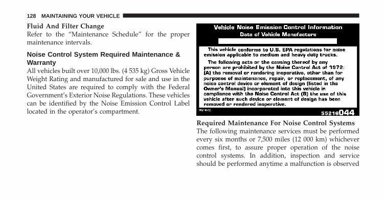
Fluid And Filter ChangeRefer to the “Maintenance Schedule” for the propermaintenance intervals.
Noise Control System Required Maintenance &WarrantyAll vehicles built over 10,000 lbs. (4 535 kg) Gross VehicleWeight Rating and manufactured for sale and use in theUnited States are required to comply with the FederalGovernment’s Exterior Noise Regulations. These vehiclescan be identified by the Noise Emission Control Labellocated in the operator’s compartment.
Required Maintenance For Noise Control SystemsThe following maintenance services must be performedevery six months or 7,500 miles (12 000 km) whichevercomes first, to assure proper operation of the noisecontrol systems. In addition, inspection and serviceshould be performed anytime a malfunction is observed
128 MAINTAINING YOUR VEHICLE
or suspected. Proper maintenance of the entire vehiclewill help the effectiveness of the noise control systems.
Exhaust SystemInspect the entire exhaust system for leaks and damagedparts. Devices such as hangers, clamps, and U-boltsshould be tight and in good condition. Damaged compo-nents, burned or blown out mufflers, burned or rustedout exhaust pipes should be replaced according to theprocedures and specifications outlined in the appropriateservice manual.
Air Cleaner AssemblyInspect air cleaner housing for proper assembly and fit.Make certain that the air cleaner is properly positionedand that the cover is tight. Check all hoses leading to theair cleaner for tightness. The air filter element must alsobe clean and serviced according to the instructions out-lined in the Maintenance Schedule section of this manual.
Tampering With Noise Control System ProhibitedFederal law prohibits the following acts or the causingthereof: (1) the removal or rendering inoperative by anyperson, other than for purposes of maintenance, repair, orreplacement, of any device or element of design incorpo-rated into any new vehicle for the purpose of noisecontrol prior to its sale or delivery to the ultimatepurchaser or while it is in use, or (2) the use of the vehicleafter such device or element of design has been removedor rendered inoperative by any person.
Among those acts presumed to constitute tampering arethe acts listed below.
• AIR CLEANER
− Removal of the air cleaner.
− Removal of the air cleaner filter element from the aircleaner housing.
− Removal of the air ducting.
6
MAINTAINING YOUR VEHICLE 129
• EXHAUST SYSTEM
− Removal or rendering inoperative exhaust systemcomponents including the muffler or tailpipe.
• ENGINE COOLING SYSTEM
− Removal or rendering inoperative the fan clutch.
− Removal of the fan shroud.
Noise Emission WarrantyThe manufacturer warrants that this vehicle as manufac-tured by the manufacturer, was designed, built andequipped to conform at the time it left the manufacturer’s
control with all applicable U.S. EPA Noise Control Regu-lations.
This warranty covers this vehicle as designed, built andequipped by the manufacturer, and is not limited to anyparticular part, component or system of the vehiclemanufactured by the manufacturer. Defects in design,assembly or in any part, component or system of thevehicle as manufactured by the manufacturer, which, atthe time it left the manufacturer’s control, caused noiseemissions to exceed Federal standards, are covered bythis warranty for the life of the vehicle.
130 MAINTAINING YOUR VEHICLE
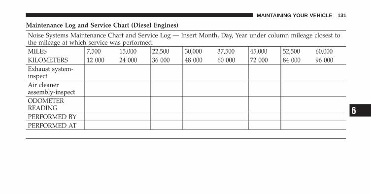
Maintenance Log and Service Chart (Diesel Engines)
Noise Systems Maintenance Chart and Service Log — Insert Month, Day, Year under column mileage closest tothe mileage at which service was performed.MILES 7,500 15,000 22,500 30,000 37,500 45,000 52,500 60,000KILOMETERS 12 000 24 000 36 000 48 000 60 000 72 000 84 000 96 000Exhaust system-inspectAir cleanerassembly-inspectODOMETERREADINGPERFORMED BYPERFORMED AT
6
MAINTAINING YOUR VEHICLE 131
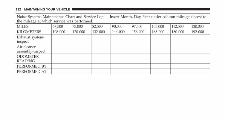
Noise Systems Maintenance Chart and Service Log — Insert Month, Day, Year under column mileage closest tothe mileage at which service was performed.MILES 67,500 75,000 82,500 90,000 97,500 105,000 112,500 120,000KILOMETERS 108 000 120 000 132 000 144 000 156 000 168 000 180 000 192 000Exhaust system-inspectAir cleanerassembly-inspectODOMETERREADINGPERFORMED BYPERFORMED AT
132 MAINTAINING YOUR VEHICLE
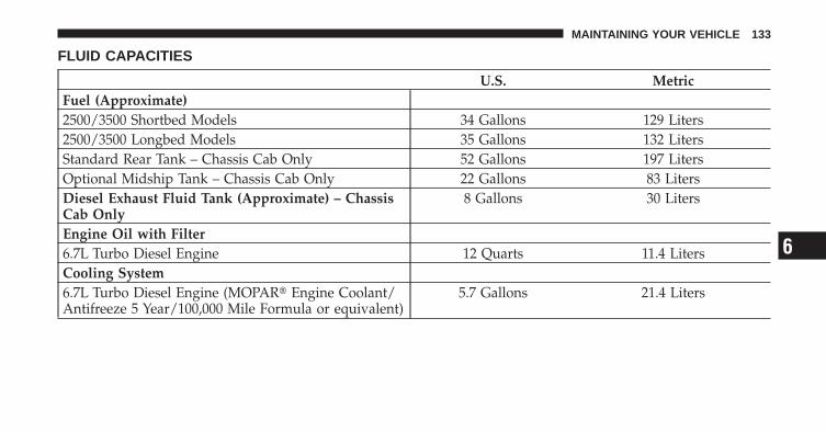
FLUID CAPACITIES
U.S. MetricFuel (Approximate)2500/3500 Shortbed Models 34 Gallons 129 Liters2500/3500 Longbed Models 35 Gallons 132 LitersStandard Rear Tank – Chassis Cab Only 52 Gallons 197 LitersOptional Midship Tank – Chassis Cab Only 22 Gallons 83 LitersDiesel Exhaust Fluid Tank (Approximate) – ChassisCab Only
8 Gallons 30 Liters
Engine Oil with Filter6.7L Turbo Diesel Engine 12 Quarts 11.4 LitersCooling System6.7L Turbo Diesel Engine (MOPAR� Engine Coolant/Antifreeze 5 Year/100,000 Mile Formula or equivalent)
5.7 Gallons 21.4 Liters
6
MAINTAINING YOUR VEHICLE 133
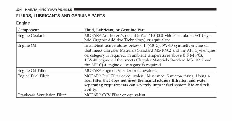
FLUIDS, LUBRICANTS AND GENUINE PARTS
Engine
Component Fluid, Lubricant, or Genuine PartEngine Coolant MOPAR� Antifreeze/Coolant 5 Year/100,000 Mile Formula HOAT (Hy-
brid Organic Additive Technology) or equivalent.Engine Oil In ambient temperatures below 0°F (-18°C), 5W-40 synthetic engine oil
that meets Chrysler Materials Standard MS-10902 and the API CJ-4 engineoil category is required. In ambient temperatures above 0°F (-18°C),15W-40 engine oil that meets Chrysler Materials Standard MS-10902 andthe API CJ-4 engine oil category is required.
Engine Oil Filter MOPAR� Engine Oil Filter or equivalent.Engine Fuel Filter MOPAR� Fuel Filter or equivalent. Must meet 5 micron rating. Using a
fuel filter that does not meet the manufacturers filtration and waterseparating requirements can severely impact fuel system life and reli-ability.
Crankcase Ventilation Filter MOPAR� CCV Filter or equivalent.
134 MAINTAINING YOUR VEHICLE
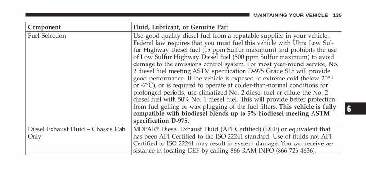
Component Fluid, Lubricant, or Genuine PartFuel Selection Use good quality diesel fuel from a reputable supplier in your vehicle.
Federal law requires that you must fuel this vehicle with Ultra Low Sul-fur Highway Diesel fuel (15 ppm Sulfur maximum) and prohibits the useof Low Sulfur Highway Diesel fuel (500 ppm Sulfur maximum) to avoiddamage to the emissions control system. For most year-round service, No.2 diesel fuel meeting ASTM specification D-975 Grade S15 will providegood performance. If the vehicle is exposed to extreme cold (below 20°For -7°C), or is required to operate at colder-than-normal conditions forprolonged periods, use climatized No. 2 diesel fuel or dilute the No. 2diesel fuel with 50% No. 1 diesel fuel. This will provide better protectionfrom fuel gelling or wax-plugging of the fuel filters. This vehicle is fullycompatible with biodiesel blends up to 5% biodiesel meeting ASTMspecification D-975.
Diesel Exhaust Fluid – Chassis CabOnly
MOPAR� Diesel Exhaust Fluid (API Certified) (DEF) or equivalent thathas been API Certified to the ISO 22241 standard. Use of fluids not APICertified to ISO 22241 may result in system damage. You can receive as-sistance in locating DEF by calling 866-RAM-INFO (866-726-4636).
6
MAINTAINING YOUR VEHICLE 135
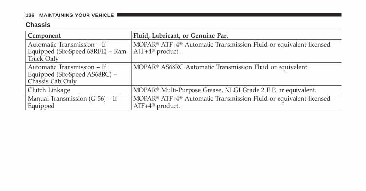
Chassis
Component Fluid, Lubricant, or Genuine PartAutomatic Transmission – IfEquipped (Six-Speed 68RFE) – RamTruck Only
MOPAR� ATF+4� Automatic Transmission Fluid or equivalent licensedATF+4� product.
Automatic Transmission – IfEquipped (Six-Speed AS68RC) –Chassis Cab Only
MOPAR� AS68RC Automatic Transmission Fluid or equivalent.
Clutch Linkage MOPAR� Multi-Purpose Grease, NLGI Grade 2 E.P. or equivalent.Manual Transmission (G-56) – IfEquipped
MOPAR� ATF+4� Automatic Transmission Fluid or equivalent licensedATF+4� product.
136 MAINTAINING YOUR VEHICLE
MAINTENANCE SCHEDULES
CONTENTS
� Maintenance Schedule . . . . . . . . . . . . . . . . . . 138
▫ Oil Change Indicator System . . . . . . . . . . . . 139
▫ Perform Service Indicator . . . . . . . . . . . . . . 140
▫ Required Maintenance Intervals . . . . . . . . . . 140
7
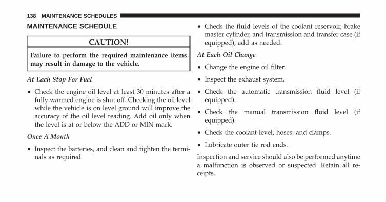
MAINTENANCE SCHEDULE
CAUTION!
Failure to perform the required maintenance itemsmay result in damage to the vehicle.
At Each Stop For Fuel
• Check the engine oil level at least 30 minutes after afully warmed engine is shut off. Checking the oil levelwhile the vehicle is on level ground will improve theaccuracy of the oil level reading. Add oil only whenthe level is at or below the ADD or MIN mark.
Once A Month
• Inspect the batteries, and clean and tighten the termi-nals as required.
• Check the fluid levels of the coolant reservoir, brakemaster cylinder, and transmission and transfer case (ifequipped), add as needed.
At Each Oil Change
• Change the engine oil filter.
• Inspect the exhaust system.
• Check the automatic transmission fluid level (ifequipped).
• Check the manual transmission fluid level (ifequipped).
• Check the coolant level, hoses, and clamps.
• Lubricate outer tie rod ends.
Inspection and service should also be performed anytimea malfunction is observed or suspected. Retain all re-ceipts.
138 MAINTENANCE SCHEDULES
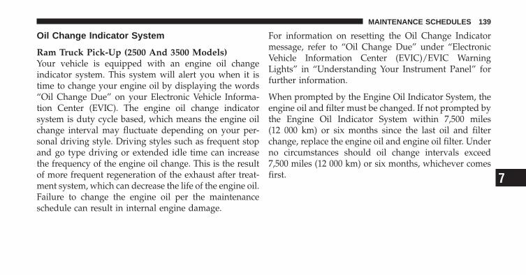
Oil Change Indicator System
Ram Truck Pick-Up (2500 And 3500 Models)Your vehicle is equipped with an engine oil changeindicator system. This system will alert you when it istime to change your engine oil by displaying the words“Oil Change Due” on your Electronic Vehicle Informa-tion Center (EVIC). The engine oil change indicatorsystem is duty cycle based, which means the engine oilchange interval may fluctuate depending on your per-sonal driving style. Driving styles such as frequent stopand go type driving or extended idle time can increasethe frequency of the engine oil change. This is the resultof more frequent regeneration of the exhaust after treat-ment system, which can decrease the life of the engine oil.Failure to change the engine oil per the maintenanceschedule can result in internal engine damage.
For information on resetting the Oil Change Indicatormessage, refer to “Oil Change Due” under “ElectronicVehicle Information Center (EVIC)/EVIC WarningLights” in “Understanding Your Instrument Panel” forfurther information.
When prompted by the Engine Oil Indicator System, theengine oil and filter must be changed. If not prompted bythe Engine Oil Indicator System within 7,500 miles(12 000 km) or six months since the last oil and filterchange, replace the engine oil and engine oil filter. Underno circumstances should oil change intervals exceed7,500 miles (12 000 km) or six months, whichever comesfirst. 7
MAINTENANCE SCHEDULES 139
Ram Truck Chassis Cab (3500, 4500, And 5500Models)Replace the engine oil and oil filter every 7,500 miles(12 000 km) or six months, or sooner if prompted by theoil change indicator system (if equipped). Under nocircumstances should oil change intervals exceed7,500 miles (12 000 km) or six months, whichever comesfirst.
Perform Service IndicatorYour vehicle will require emissions maintenance at a setinterval. To help remind you when this maintenance isdue, the Electronic Vehicle Information Center (EVIC)will display “Perform Service”. When the “Perform Ser-vice” message is displayed on the EVIC it is necessary tohave the emissions maintenance performed. Emissionsmaintenance may include replacing the Closed Crank-case Ventilation (CCV) filter element, and cleaning of the
EGR Cooler. The procedure for clearing and resetting the“Perform Service” indicator message is located in theappropriate Service Information.
Required Maintenance IntervalsRefer to the Maintenance Schedules on the followingpages for the required maintenance intervals.
140 MAINTENANCE SCHEDULES

7,500 Miles (12,000 km) or 6 Months Maintenance ServiceSchedule❏ When prompted by the Engine Oil Indicator System, the engine oil and filter must be
changed. If not prompted by the Engine Oil Indicator System within 7,500 miles(12 000 km) or six months since the last oil and filter change, change the engine oil andengine oil filter.
❏ Check the Diesel Exhaust Fluid (DEF) tank, refill if necessary (Chassis Cab Only).❏ Rotate tires.❏ Lubricate front drive shaft fitting (4x4).❏ Lubricate outer tie rod ends.
Odometer Reading Date
Repair Order # Dealer Code
Signature, Authorized Service Center
7
MAINTENANCE SCHEDULES 141
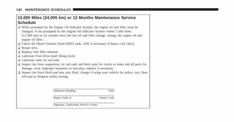
15,000 Miles (24,000 km) or 12 Months Maintenance ServiceSchedule❏ When prompted by the Engine Oil Indicator System, the engine oil and filter must be
changed. If not prompted by the Engine Oil Indicator System within 7,500 miles(12 000 km) or six months since the last oil and filter change, change the engine oil andengine oil filter.
❏ Check the Diesel Exhaust Fluid (DEF) tank, refill if necessary (Chassis Cab Only).❏ Rotate tires.❏ Replace fuel filter element.❏ Lubricate front drive shaft fitting (4x4).❏ Lubricate outer tie rod ends.❏ Inspect the front suspension, tie rod ends and boot seals for cracks or leaks and all parts for
damage, wear, improper looseness or end play; replace if necessary.❏ Inspect the front (4x4) and rear axle fluid, change if using your vehicle for police, taxi, fleet,
off-road or frequent trailer towing.
Odometer Reading Date
Repair Order # Dealer Code
Signature, Authorized Service Center
142 MAINTENANCE SCHEDULES

22,500 Miles (36,000 km) or 18 Months Maintenance ServiceSchedule❏ When prompted by the Engine Oil Indicator System, the engine oil and filter must be
changed. If not prompted by the Engine Oil Indicator System within 7,500 miles(12 000 km) or six months since the last oil and filter change, change the engine oil andengine oil filter.
❏ Check the Diesel Exhaust Fluid (DEF) tank, refill if necessary (Chassis Cab Only).❏ Rotate tires.❏ Inspect drive belt, replace if necessary.❏ Lubricate front drive shaft fitting (4x4).❏ Lubricate outer tie rod ends.❏ Inspect brake linings.❏ Inspect and adjust parking brake if necessary.
Odometer Reading Date
Repair Order # Dealer Code
Signature, Authorized Service Center
7
MAINTENANCE SCHEDULES 143
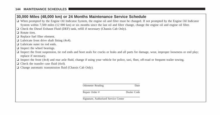
30,000 Miles (48,000 km) or 24 Months Maintenance Service Schedule❏ When prompted by the Engine Oil Indicator System, the engine oil and filter must be changed. If not prompted by the Engine Oil Indicator
System within 7,500 miles (12 000 km) or six months since the last oil and filter change, change the engine oil and engine oil filter.❏ Check the Diesel Exhaust Fluid (DEF) tank, refill if necessary (Chassis Cab Only).❏ Rotate tires.❏ Replace fuel filter element.❏ Lubricate front drive shaft fitting (4x4).❏ Lubricate outer tie rod ends.❏ Inspect the wheel bearings.❏ Inspect the front suspension, tie rod ends and boot seals for cracks or leaks and all parts for damage, wear, improper looseness or end play;
replace if necessary.❏ Inspect the front (4x4) and rear axle fluid, change if using your vehicle for police, taxi, fleet, off-road or frequent trailer towing.❏ Check the transfer case fluid (4x4).❏ Change automatic transmission fluid (Chassis Cab Only).
Odometer Reading Date
Repair Order # Dealer Code
Signature, Authorized Service Center
144 MAINTENANCE SCHEDULES

37,500 Miles (60,000 km) or 30 Months Maintenance ServiceSchedule❏ When prompted by the Engine Oil Indicator System, the engine oil and filter must be
changed. If not prompted by the Engine Oil Indicator System within 7,500 miles(12 000 km) or six months since the last oil and filter change, change the engine oil andengine oil filter.
❏ Check the Diesel Exhaust Fluid (DEF) tank, refill if necessary (Chassis Cab Only).❏ Rotate tires.❏ Lubricate front drive shaft fitting (4x4).❏ Lubricate outer tie rod ends.
Odometer Reading Date
Repair Order # Dealer Code
Signature, Authorized Service Center
7
MAINTENANCE SCHEDULES 145
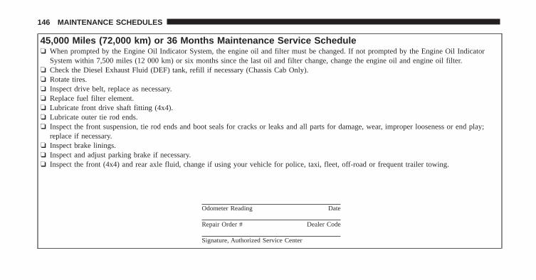
45,000 Miles (72,000 km) or 36 Months Maintenance Service Schedule❏ When prompted by the Engine Oil Indicator System, the engine oil and filter must be changed. If not prompted by the Engine Oil Indicator
System within 7,500 miles (12 000 km) or six months since the last oil and filter change, change the engine oil and engine oil filter.❏ Check the Diesel Exhaust Fluid (DEF) tank, refill if necessary (Chassis Cab Only).❏ Rotate tires.❏ Inspect drive belt, replace as necessary.❏ Replace fuel filter element.❏ Lubricate front drive shaft fitting (4x4).❏ Lubricate outer tie rod ends.❏ Inspect the front suspension, tie rod ends and boot seals for cracks or leaks and all parts for damage, wear, improper looseness or end play;
replace if necessary.❏ Inspect brake linings.❏ Inspect and adjust parking brake if necessary.❏ Inspect the front (4x4) and rear axle fluid, change if using your vehicle for police, taxi, fleet, off-road or frequent trailer towing.
Odometer Reading Date
Repair Order # Dealer Code
Signature, Authorized Service Center
146 MAINTENANCE SCHEDULES

52,500 Miles (84,000 km) or 42 Months Maintenance ServiceSchedule❏ When prompted by the Engine Oil Indicator System, the engine oil and filter must be
changed. If not prompted by the Engine Oil Indicator System within 7,500 miles(12 000 km) or six months since the last oil and filter change, change the engine oil andengine oil filter.
❏ Check the Diesel Exhaust Fluid (DEF) tank, refill if necessary (Chassis Cab Only).❏ Rotate tires.❏ Lubricate front drive shaft fitting (4x4).❏ Lubricate outer tie rod ends.
Odometer Reading Date
Repair Order # Dealer Code
Signature, Authorized Service Center
7
MAINTENANCE SCHEDULES 147
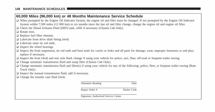
60,000 Miles (96,000 km) or 48 Months Maintenance Service Schedule❏ When prompted by the Engine Oil Indicator System, the engine oil and filter must be changed. If not prompted by the Engine Oil Indicator
System within 7,500 miles (12 000 km) or six months since the last oil and filter change, change the engine oil and engine oil filter.❏ Check the Diesel Exhaust Fluid (DEF) tank, refill if necessary (Chassis Cab Only).❏ Rotate tires.❏ Replace fuel filter element.❏ Lubricate front drive shaft fitting (4x4).❏ Lubricate outer tie rod ends.❏ Inspect the wheel bearings.❏ Inspect the front suspension, tie rod ends and boot seals for cracks or leaks and all parts for damage, wear, improper looseness or end play;
replace if necessary.❏ Inspect the front (4x4) and rear axle fluid, change if using your vehicle for police, taxi, fleet, off-road or frequent trailer towing.❏ Change automatic transmission fluid and sump filter (Chassis Cab Only).❏ Change automatic transmission fluid and filter(s) if using your vehicle for any of the following: police, fleet, or frequent trailer towing (Ram
Truck Only).❏ Inspect the manual transmission fluid, add if necessary.❏ Change the transfer case fluid (4x4).
Odometer Reading Date
Repair Order # Dealer Code
Signature, Authorized Service Center
148 MAINTENANCE SCHEDULES
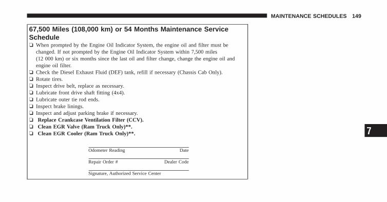
67,500 Miles (108,000 km) or 54 Months Maintenance ServiceSchedule❏ When prompted by the Engine Oil Indicator System, the engine oil and filter must be
changed. If not prompted by the Engine Oil Indicator System within 7,500 miles(12 000 km) or six months since the last oil and filter change, change the engine oil andengine oil filter.
❏ Check the Diesel Exhaust Fluid (DEF) tank, refill if necessary (Chassis Cab Only).❏ Rotate tires.❏ Inspect drive belt, replace as necessary.❏ Lubricate front drive shaft fitting (4x4).❏ Lubricate outer tie rod ends.❏ Inspect brake linings.❏ Inspect and adjust parking brake if necessary.❏ Replace Crankcase Ventilation Filter (CCV).❏ Clean EGR Valve (Ram Truck Only)**.❏ Clean EGR Cooler (Ram Truck Only)**.
Odometer Reading Date
Repair Order # Dealer Code
Signature, Authorized Service Center
7
MAINTENANCE SCHEDULES 149
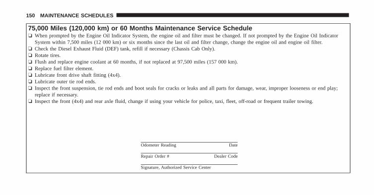
75,000 Miles (120,000 km) or 60 Months Maintenance Service Schedule❏ When prompted by the Engine Oil Indicator System, the engine oil and filter must be changed. If not prompted by the Engine Oil Indicator
System within 7,500 miles (12 000 km) or six months since the last oil and filter change, change the engine oil and engine oil filter.❏ Check the Diesel Exhaust Fluid (DEF) tank, refill if necessary (Chassis Cab Only).❏ Rotate tires.❏ Flush and replace engine coolant at 60 months, if not replaced at 97,500 miles (157 000 km).❏ Replace fuel filter element.❏ Lubricate front drive shaft fitting (4x4).❏ Lubricate outer tie rod ends.❏ Inspect the front suspension, tie rod ends and boot seals for cracks or leaks and all parts for damage, wear, improper looseness or end play;
replace if necessary.❏ Inspect the front (4x4) and rear axle fluid, change if using your vehicle for police, taxi, fleet, off-road or frequent trailer towing.
Odometer Reading Date
Repair Order # Dealer Code
Signature, Authorized Service Center
150 MAINTENANCE SCHEDULES
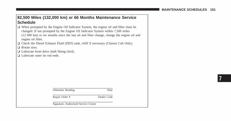
82,500 Miles (132,000 km) or 66 Months Maintenance ServiceSchedule❏ When prompted by the Engine Oil Indicator System, the engine oil and filter must be
changed. If not prompted by the Engine Oil Indicator System within 7,500 miles(12 000 km) or six months since the last oil and filter change, change the engine oil andengine oil filter.
❏ Check the Diesel Exhaust Fluid (DEF) tank, refill if necessary (Chassis Cab Only).❏ Rotate tires.❏ Lubricate front drive shaft fitting (4x4).❏ Lubricate outer tie rod ends.
Odometer Reading Date
Repair Order # Dealer Code
Signature, Authorized Service Center
7
MAINTENANCE SCHEDULES 151
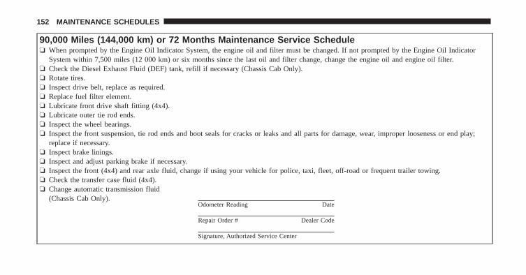
90,000 Miles (144,000 km) or 72 Months Maintenance Service Schedule❏ When prompted by the Engine Oil Indicator System, the engine oil and filter must be changed. If not prompted by the Engine Oil Indicator
System within 7,500 miles (12 000 km) or six months since the last oil and filter change, change the engine oil and engine oil filter.❏ Check the Diesel Exhaust Fluid (DEF) tank, refill if necessary (Chassis Cab Only).❏ Rotate tires.❏ Inspect drive belt, replace as required.❏ Replace fuel filter element.❏ Lubricate front drive shaft fitting (4x4).❏ Lubricate outer tie rod ends.❏ Inspect the wheel bearings.❏ Inspect the front suspension, tie rod ends and boot seals for cracks or leaks and all parts for damage, wear, improper looseness or end play;
replace if necessary.❏ Inspect brake linings.❏ Inspect and adjust parking brake if necessary.❏ Inspect the front (4x4) and rear axle fluid, change if using your vehicle for police, taxi, fleet, off-road or frequent trailer towing.❏ Check the transfer case fluid (4x4).❏ Change automatic transmission fluid
(Chassis Cab Only).Odometer Reading Date
Repair Order # Dealer Code
Signature, Authorized Service Center
152 MAINTENANCE SCHEDULES

97,500 Miles (157,000 km) or 78 Months Maintenance ServiceSchedule❏ When prompted by the Engine Oil Indicator System, the engine oil and filter must be
changed. If not prompted by the Engine Oil Indicator System within 7,500 miles(12 000 km) or six months since the last oil and filter change, change the engine oil andengine oil filter.
❏ Check the Diesel Exhaust Fluid (DEF) tank, refill if necessary (Chassis Cab Only).❏ Flush and replace engine coolant.❏ Rotate tires.❏ Lubricate front drive shaft fitting (4x4).❏ Lubricate outer tie rod ends.❏ Flush and replace power steering fluid (3500 Ram Truck Only).
Odometer Reading Date
Repair Order # Dealer Code
Signature, Authorized Service Center
7
MAINTENANCE SCHEDULES 153
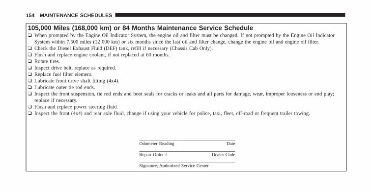
105,000 Miles (168,000 km) or 84 Months Maintenance Service Schedule❏ When prompted by the Engine Oil Indicator System, the engine oil and filter must be changed. If not prompted by the Engine Oil Indicator
System within 7,500 miles (12 000 km) or six months since the last oil and filter change, change the engine oil and engine oil filter.❏ Check the Diesel Exhaust Fluid (DEF) tank, refill if necessary (Chassis Cab Only).❏ Flush and replace engine coolant, if not replaced at 60 months.❏ Rotate tires.❏ Inspect drive belt, replace as required.❏ Replace fuel filter element.❏ Lubricate front drive shaft fitting (4x4).❏ Lubricate outer tie rod ends.❏ Inspect the front suspension, tie rod ends and boot seals for cracks or leaks and all parts for damage, wear, improper looseness or end play;
replace if necessary.❏ Flush and replace power steering fluid.❏ Inspect the front (4x4) and rear axle fluid, change if using your vehicle for police, taxi, fleet, off-road or frequent trailer towing.
Odometer Reading Date
Repair Order # Dealer Code
Signature, Authorized Service Center
154 MAINTENANCE SCHEDULES
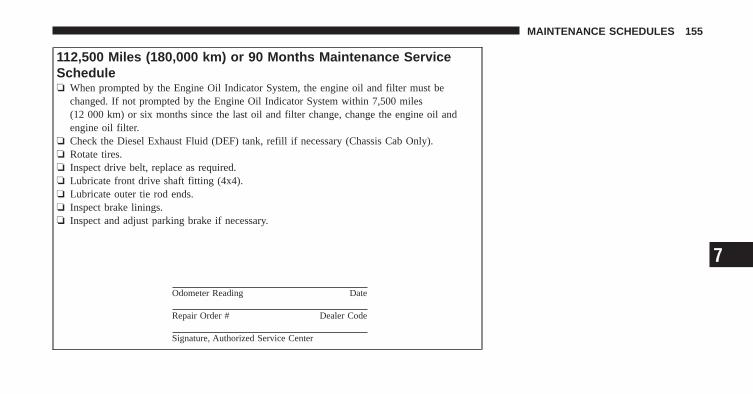
112,500 Miles (180,000 km) or 90 Months Maintenance ServiceSchedule❏ When prompted by the Engine Oil Indicator System, the engine oil and filter must be
changed. If not prompted by the Engine Oil Indicator System within 7,500 miles(12 000 km) or six months since the last oil and filter change, change the engine oil andengine oil filter.
❏ Check the Diesel Exhaust Fluid (DEF) tank, refill if necessary (Chassis Cab Only).❏ Rotate tires.❏ Inspect drive belt, replace as required.❏ Lubricate front drive shaft fitting (4x4).❏ Lubricate outer tie rod ends.❏ Inspect brake linings.❏ Inspect and adjust parking brake if necessary.
Odometer Reading Date
Repair Order # Dealer Code
Signature, Authorized Service Center
7
MAINTENANCE SCHEDULES 155
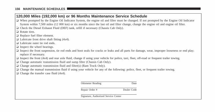
120,000 Miles (192,000 km) or 96 Months Maintenance Service Schedule❏ When prompted by the Engine Oil Indicator System, the engine oil and filter must be changed. If not prompted by the Engine Oil Indicator
System within 7,500 miles (12 000 km) or six months since the last oil and filter change, change the engine oil and engine oil filter.❏ Check the Diesel Exhaust Fluid (DEF) tank, refill if necessary (Chassis Cab Only).❏ Rotate tires.❏ Replace fuel filter element.❏ Lubricate front drive shaft fitting (4x4).❏ Lubricate outer tie rod ends.❏ Inspect the wheel bearings.❏ Inspect the front suspension, tie rod ends and boot seals for cracks or leaks and all parts for damage, wear, improper looseness or end play;
replace if necessary.❏ Inspect the front (4x4) and rear axle fluid, change if using your vehicle for police, taxi, fleet, off-road or frequent trailer towing.❏ Change automatic transmission fluid and sump filter (Chassis Cab Only).❏ Change automatic transmission fluid and filter(s) (Ram Truck Only).❏ Change the manual transmission fluid if using your vehicle for any of the following: police, fleet, or frequent trailer towing.❏ Change the transfer case fluid (4x4).
Odometer Reading Date
Repair Order # Dealer Code
Signature, Authorized Service Center
156 MAINTENANCE SCHEDULES

127,500 Miles (204,000 km) or 102 Months Maintenance ServiceSchedule❏ When prompted by the Engine Oil Indicator System, the engine oil and filter must be
changed. If not prompted by the Engine Oil Indicator System within 7,500 miles(12 000 km) or six months since the last oil and filter change, change the engine oil andengine oil filter.
❏ Check the Diesel Exhaust Fluid (DEF) tank, refill if necessary (Chassis Cab Only).❏ Rotate tires.❏ Lubricate front drive shaft fitting (4x4).❏ Lubricate outer tie rod ends.
Odometer Reading Date
Repair Order # Dealer Code
Signature, Authorized Service Center
7
MAINTENANCE SCHEDULES 157
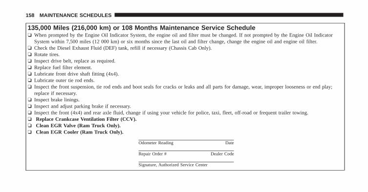
135,000 Miles (216,000 km) or 108 Months Maintenance Service Schedule❏ When prompted by the Engine Oil Indicator System, the engine oil and filter must be changed. If not prompted by the Engine Oil Indicator
System within 7,500 miles (12 000 km) or six months since the last oil and filter change, change the engine oil and engine oil filter.❏ Check the Diesel Exhaust Fluid (DEF) tank, refill if necessary (Chassis Cab Only).❏ Rotate tires.❏ Inspect drive belt, replace as required.❏ Replace fuel filter element.❏ Lubricate front drive shaft fitting (4x4).❏ Lubricate outer tie rod ends.❏ Inspect the front suspension, tie rod ends and boot seals for cracks or leaks and all parts for damage, wear, improper looseness or end play;
replace if necessary.❏ Inspect brake linings.❏ Inspect and adjust parking brake if necessary.❏ Inspect the front (4x4) and rear axle fluid, change if using your vehicle for police, taxi, fleet, off-road or frequent trailer towing.❏ Replace Crankcase Ventilation Filter (CCV).❏ Clean EGR Valve (Ram Truck Only).❏ Clean EGR Cooler (Ram Truck Only).
Odometer Reading Date
Repair Order # Dealer Code
Signature, Authorized Service Center
158 MAINTENANCE SCHEDULES

142,500 Miles (228,000 km) or 114 Months Maintenance ServiceSchedule❏ When prompted by the Engine Oil Indicator System, the engine oil and filter must be
changed. If not prompted by the Engine Oil Indicator System within 7,500 miles(12 000 km) or six months since the last oil and filter change, change the engine oil andengine oil filter.
❏ Check the Diesel Exhaust Fluid (DEF) tank, refill if necessary (Chassis Cab Only).❏ Rotate tires.❏ Lubricate front drive shaft fitting (4x4).❏ Lubricate outer tie rod ends.
Odometer Reading Date
Repair Order # Dealer Code
Signature, Authorized Service Center
7
MAINTENANCE SCHEDULES 159
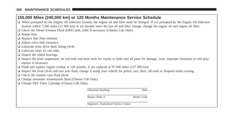
150,000 Miles (240,000 km) or 120 Months Maintenance Service Schedule❏ When prompted by the Engine Oil Indicator System, the engine oil and filter must be changed. If not prompted by the Engine Oil Indicator
System within 7,500 miles (12 000 km) or six months since the last oil and filter change, change the engine oil and engine oil filter.❏ Check the Diesel Exhaust Fluid (DEF) tank, refill if necessary (Chassis Cab Only).❏ Rotate tires.❏ Replace fuel filter element.❏ Adjust valve lash clearance.❏ Lubricate front drive shaft fitting (4x4).❏ Lubricate outer tie rod ends.❏ Inspect the wheel bearings.❏ Inspect the front suspension, tie rod ends and boot seals for cracks or leaks and all parts for damage, wear, improper looseness or end play;
replace if necessary.❏ Flush and replace engine coolant at 120 months, if not replaced at 97,500 miles (157 000 km).❏ Inspect the front (4x4) and rear axle fluid, change if using your vehicle for police, taxi, fleet, off-road or frequent trailer towing.❏ Check the transfer case fluid (4x4).❏ Change automatic transmission fluid (Chassis Cab Only).❏ Change DEF Filter Cartridge (Chassis Cab Only)
Odometer Reading Date
Repair Order # Dealer Code
Signature, Authorized Service Center
160 MAINTENANCE SCHEDULES
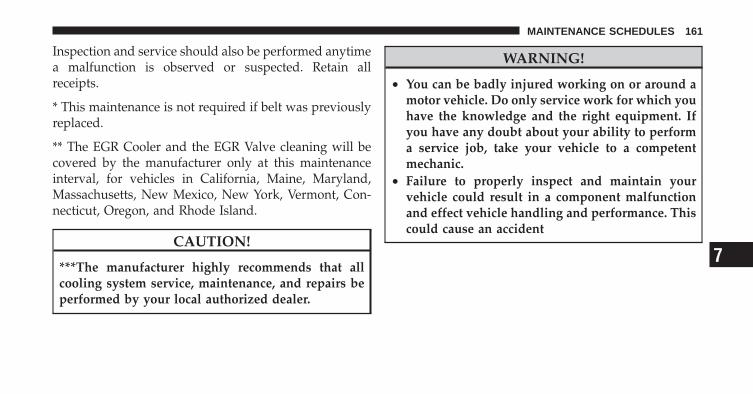
Inspection and service should also be performed anytimea malfunction is observed or suspected. Retain allreceipts.
* This maintenance is not required if belt was previouslyreplaced.
** The EGR Cooler and the EGR Valve cleaning will becovered by the manufacturer only at this maintenanceinterval, for vehicles in California, Maine, Maryland,Massachusetts, New Mexico, New York, Vermont, Con-necticut, Oregon, and Rhode Island.
CAUTION!
***The manufacturer highly recommends that allcooling system service, maintenance, and repairs beperformed by your local authorized dealer.
WARNING!
• You can be badly injured working on or around amotor vehicle. Do only service work for which youhave the knowledge and the right equipment. Ifyou have any doubt about your ability to performa service job, take your vehicle to a competentmechanic.
• Failure to properly inspect and maintain yourvehicle could result in a component malfunctionand effect vehicle handling and performance. Thiscould cause an accident
7
MAINTENANCE SCHEDULES 161

INDEX
8
Adding Fuel . . . . . . . . . . . . . . . . . . . . . . . . . . . . 83Air Cleaner, Engine (Engine Air CleanerFilter) . . . . . . . . . . . . . . . . . . . . . . . . . . . . . 104,129Air Filter . . . . . . . . . . . . . . . . . . . . . . . . . . . . . . 104Airbag Light . . . . . . . . . . . . . . . . . . . . . . . . . . . . 24Alarm Light . . . . . . . . . . . . . . . . . . . . . . . . . . . . 17Anti-Lock Warning Light . . . . . . . . . . . . . . . . . . . 21Antifreeze (Engine Coolant) . . . . . . . . . . . . . . 116,117
Capacities . . . . . . . . . . . . . . . . . . . . . . . . . . 133Disposal . . . . . . . . . . . . . . . . . . . . . . . . . . . 119
Automatic Transmission . . . . . . . . . . . . . . . . . . . . 64Adding Fluid . . . . . . . . . . . . . . . . . . . . . . . 125Fluid Level Check . . . . . . . . . . . . . . . . . . . . 124Fluid Type . . . . . . . . . . . . . . . . . . . . . . 124,136Shifting . . . . . . . . . . . . . . . . . . . . . . . . . . . . 54
Axle Fluid . . . . . . . . . . . . . . . . . . . . . . . . . . . . . 136
Battery . . . . . . . . . . . . . . . . . . . . . . . . . . . . . . . 114Blanket . . . . . . . . . . . . . . . . . . . . . . . . . . 43,115
Emergency Starting . . . . . . . . . . . . . . . . . . . . 92Brake Fluid . . . . . . . . . . . . . . . . . . . . . . . . . . . . 136Brake System . . . . . . . . . . . . . . . . . . . . . . . . . . . 121
Fluid Check . . . . . . . . . . . . . . . . . . . . . . . . 121Master Cylinder . . . . . . . . . . . . . . . . . . . . . 121Warning Light . . . . . . . . . . . . . . . . . . . . . . . 19
Brake/Transmission Interlock . . . . . . . . . . . . . . . . 53
Capacities, Antifreeze (Engine Coolant) . . . . . . . . 133Capacities, Fluid . . . . . . . . . . . . . . . . . . . . . . . . 133Caps, Filler
Oil (Engine) . . . . . . . . . . . . . . . . . . . . . . . . 103Radiator (Coolant Pressure) . . . . . . . . . . . . . 118
Charge Air Cooler . . . . . . . . . . . . . . . . . . . . . . . 121Check Engine Light (Malfunction IndicatorLight) . . . . . . . . . . . . . . . . . . . . . . . . . . . . . . . . . 23Coolant Pressure Cap (Radiator Cap) . . . . . . . . . . 118Cooling System . . . . . . . . . . . . . . . . . . . . . . . . . 115
Adding Coolant (Antifreeze) . . . . . . . . . . . . . 117
164 INDEX
Coolant Capacity . . . . . . . . . . . . . . . . . . . . . 133Coolant Level . . . . . . . . . . . . . . . . . . . . 115,119Disposal of Used Coolant . . . . . . . . . . . . . . . 119Drain, Flush, and Refill . . . . . . . . . . . . . . . . 116Inspection . . . . . . . . . . . . . . . . . . . . . . . . . . 119Points to Remember . . . . . . . . . . . . . . . . . . 120Pressure Cap . . . . . . . . . . . . . . . . . . . . . . . . 118Radiator Cap . . . . . . . . . . . . . . . . . . . . . . . . 118Selection of Coolant (Antifreeze) . . . . . . . 116,134
Diesel Exhaust Brake . . . . . . . . . . . . . . . . . . . . . . 50Diesel Fuel . . . . . . . . . . . . . . . . . . . . . . . . . . . . . 82Diesel Fuel Requirements . . . . . . . . . . . . . . . . . . . 82
Bulk Storage of . . . . . . . . . . . . . . . . . . . . . . . 84Diesel Fuel System, Re-Priming . . . . . . . . . . . . . . 110Dipsticks . . . . . . . . . . . . . . . . . . . . . . . . . . . . . . 100Disposal . . . . . . . . . . . . . . . . . . . . . . . . . . . . . . 104
Antifreeze (Engine Coolant) . . . . . . . . . . . . . 119Engine Oil . . . . . . . . . . . . . . . . . . . . . . . . . 104
Draining Fuel/Water Separator Filter . . . . . . . . . . 106
Electronic Range Select (ERS) . . . . . . . . . . . . . . 60,71Electronic Vehicle Information Center (EVIC) . . . . . 25Emergency, In Case of
Jump Starting . . . . . . . . . . . . . . . . . . . . . . . . 92Engine . . . . . . . . . . . . . . . . . . . . . . . . . . . . . . . . 99
Air Cleaner . . . . . . . . . . . . . . . . . . . . . . . . . 104Block Heater . . . . . . . . . . . . . . . . . . . . . . . 35,49Break-In Recommendations . . . . . . . . . . . . . . 12Compartment . . . . . . . . . . . . . . . . . . . . . . . . 99Coolant (Antifreeze) . . . . . . . . . . . . . . . . . . 134Identification . . . . . . . . . . . . . . . . . . . . . . . . 99Idling . . . . . . . . . . . . . . . . . . . . . . . . . . . . . 44Jump Starting . . . . . . . . . . . . . . . . . . . . . . . . 92Oil . . . . . . . . . . . . . . . . . . . . . . . . . . . . 100,134Oil Filler Cap . . . . . . . . . . . . . . . . . . . . . . . 103Oil Synthetic . . . . . . . . . . . . . . . . . . . . . . . . 104Runaway . . . . . . . . . . . . . . . . . . . . . . . . . . . 81
8
INDEX 165
Temperature Gauge . . . . . . . . . . . . . . . . . . . . 15Exhaust Brake . . . . . . . . . . . . . . . . . . . . . . . . . . . 50Exhaust System . . . . . . . . . . . . . . . . . . . . . . . . . 129
FiltersEngine Fuel . . . . . . . . . . . . . . . . . . . . . . . . 106Engine Oil . . . . . . . . . . . . . . . . . . . . 100,104,134
FlashersTurn Signal . . . . . . . . . . . . . . . . . . . . . . . . . 15
Fluid Capacities . . . . . . . . . . . . . . . . . . . . . . . . . 133Fluid Level Checks
Brake . . . . . . . . . . . . . . . . . . . . . . . . . . . . . 121Manual Transmission . . . . . . . . . . . . . . . . . . 124Transfer Case . . . . . . . . . . . . . . . . . . . . . . . 123
Fluid, Brake . . . . . . . . . . . . . . . . . . . . . . . . . . . 136Fluids, Lubricants and Genuine Parts . . . . . . . . . . 134Fog Lights . . . . . . . . . . . . . . . . . . . . . . . . . . . . . 24Fuel . . . . . . . . . . . . . . . . . . . . . . . . . . . . . . . . 82,83
Adding . . . . . . . . . . . . . . . . . . . . . . . . . . . . 83
Diesel . . . . . . . . . . . . . . . . . . . . . . . . . 82,83,134Filter . . . . . . . . . . . . . . . . . . . . . . . . . . . . . 106Gauge . . . . . . . . . . . . . . . . . . . . . . . . . . . . . 15Requirements . . . . . . . . . . . . . . . . . . . . . . . . 82Specifications . . . . . . . . . . . . . . . . . . . . . . . . 83Tank Capacity . . . . . . . . . . . . . . . . . . . . . . . 133
GaugesCoolant Temperature . . . . . . . . . . . . . . . . . . . 15Fuel . . . . . . . . . . . . . . . . . . . . . . . . . . . . . . . 15Oil Pressure . . . . . . . . . . . . . . . . . . . . . . . . . 17Speedometer . . . . . . . . . . . . . . . . . . . . . . . . . 16Tachometer . . . . . . . . . . . . . . . . . . . . . . . . . . 15Voltmeter . . . . . . . . . . . . . . . . . . . . . . . . . 18,41
Gear Ranges . . . . . . . . . . . . . . . . . . . . . . . . 54,65,76
Idle Up Feature . . . . . . . . . . . . . . . . . . . . . . . . . . 44Information Center, Vehicle . . . . . . . . . . . . . . . . . 25Instrument Cluster . . . . . . . . . . . . . . . . . . . . . . 14,15
166 INDEX
Intervention Regeneration Strategy . . . . . . . . . . . 111
Jump Starting . . . . . . . . . . . . . . . . . . . . . . . . . . . 92
LightsAirbag . . . . . . . . . . . . . . . . . . . . . . . . . . . . . 24Alarm . . . . . . . . . . . . . . . . . . . . . . . . . . . . . 17Anti-Lock . . . . . . . . . . . . . . . . . . . . . . . . . . . 21Brake Warning . . . . . . . . . . . . . . . . . . . . . . . 19Check Engine (Malfunction Indicator) . . . . . . . 23Electronic Stability Program (ESP) Indicator . . . 17Fog . . . . . . . . . . . . . . . . . . . . . . . . . . . . . . . 24High Beam . . . . . . . . . . . . . . . . . . . . . . . . . . 18High Beam Indicator . . . . . . . . . . . . . . . . . . . 18Instrument Cluster . . . . . . . . . . . . . . . . . . . . 15Seat Belt Reminder . . . . . . . . . . . . . . . . . . . . 24Security Alarm (Theft Alarm) . . . . . . . . . . . . . 17Theft Alarm (Security Alarm) . . . . . . . . . . . . . 17Tire Pressure Monitoring (TPMS) . . . . . . . . . . 21
Traction Control . . . . . . . . . . . . . . . . . . . . . . 17Warning (Instrument Cluster Description) . . . . 15
LocksSteering Wheel . . . . . . . . . . . . . . . . . . . . . . . . 8
Maintenance Procedures . . . . . . . . . . . . . . . . . . . 100Maintenance Schedule . . . . . . . . . . . . . . . . . . . . 138Manual Transmission . . . . . . . . . . . . . . . . . . . . . . 75
Fluid Level Check . . . . . . . . . . . . . . . . . . . . 124Lubricant Selection . . . . . . . . . . . . . . . . . . . 136Shift Speeds . . . . . . . . . . . . . . . . . . . . . . . . . 76
New Vehicle Break-In Period . . . . . . . . . . . . . . . . 12Noise Control
Maintenance . . . . . . . . . . . . . . . . . . . . . . . . 128Tampering Prohibited . . . . . . . . . . . . . . . . . 129
Noise Emission Warranty . . . . . . . . . . . . . . . 128,130
Odometer . . . . . . . . . . . . . . . . . . . . . . . . . . . . 17,18
8
INDEX 167
Trip . . . . . . . . . . . . . . . . . . . . . . . . . . . . . 17,18Oil Change Indicator . . . . . . . . . . . . . . . . . . . . . 139Oil, Engine . . . . . . . . . . . . . . . . . . . . . . . . . . . . 134
Capacity . . . . . . . . . . . . . . . . . . . . . . . . . . . 133Change Interval . . . . . . . . . . . . . . . . . . . . . 101Dipstick . . . . . . . . . . . . . . . . . . . . . . . . . . . 100Disposal . . . . . . . . . . . . . . . . . . . . . . . . . . . 104Filter . . . . . . . . . . . . . . . . . . . . . . . . 100,104,134Identification Logo . . . . . . . . . . . . . . . . . . . 102Materials Added to . . . . . . . . . . . . . . . . . . . 104Pressure Gauge . . . . . . . . . . . . . . . . . . . . . . . 17Recommendation . . . . . . . . . . . . . . . . . . . . . 102Synthetic . . . . . . . . . . . . . . . . . . . . . . . . . . 104Viscosity . . . . . . . . . . . . . . . . . . . . . . . . . . . 103
Overdrive . . . . . . . . . . . . . . . . . . . . . . . . . . . . 62,72Overdrive OFF Switch . . . . . . . . . . . . . . . . . . . 62,72
Perform Service Indicator, Reset . . . . . . . . . . . . . 140
PowerTake-Off Adapter . . . . . . . . . . . . . . . . . . . . . 78Take-Off Operation . . . . . . . . . . . . . . . . . . . . 78
Power Steering Fluid . . . . . . . . . . . . . . . . . . . . . 136PTO (Power Take-Off) . . . . . . . . . . . . . . . . . . . . . 78
Radiator Cap (Coolant Pressure Cap) . . . . . . . 116,118Remote Control
Starting System . . . . . . . . . . . . . . . . . . . . . . . 8Remote Starting System . . . . . . . . . . . . . . . . . . . . . 8Resetting Perform Service Indicator . . . . . . . . . . . 140
Seat BeltsReminder . . . . . . . . . . . . . . . . . . . . . . . . . . . 24
Selection of Coolant (Antifreeze) . . . . . . . . . . 116,134Shifting . . . . . . . . . . . . . . . . . . . . . . . . . . . . . . . 52
Automatic Transmission . . . . . . . . . . . . . . . . 54Manual Transmission . . . . . . . . . . . . . . . . . . 75
168 INDEX
Signals, Turn . . . . . . . . . . . . . . . . . . . . . . . . . . . . 15Speedometer . . . . . . . . . . . . . . . . . . . . . . . . . . . . 16Starting . . . . . . . . . . . . . . . . . . . . . . . . . . . . . . 8,34
Automatic Transmission . . . . . . . . . . . . . . . . 34Engine Block Heater . . . . . . . . . . . . . . . . . 35,49Manual Transmission . . . . . . . . . . . . . . . . . . 34Remote . . . . . . . . . . . . . . . . . . . . . . . . . . . . . 8
Starting Procedures . . . . . . . . . . . . . . . . . . . . . . . 34Starting Procedures (Diesel Engines) . . . . . . . . . . . 34Steering
Wheel Lock . . . . . . . . . . . . . . . . . . . . . . . . . . 8Synthetic Engine Oil . . . . . . . . . . . . . . . . . . . . . . 104System, Remote Starting . . . . . . . . . . . . . . . . . . . . 8
Tachometer . . . . . . . . . . . . . . . . . . . . . . . . . . . . . 15Temperature Gauge, Engine Coolant . . . . . . . . . . . 15Tip Start . . . . . . . . . . . . . . . . . . . . . . . . . . . . . . . 34Tires
Pressure Warning Light . . . . . . . . . . . . . . . . . 21
Torque Converter Clutch . . . . . . . . . . . . . . . . . 63,74Tow/Haul . . . . . . . . . . . . . . . . . . . . . . . . . . . . . 62Traction Control . . . . . . . . . . . . . . . . . . . . . . . . . 123Traction Control Light . . . . . . . . . . . . . . . . . . . . . 17Transfer Case
Fluid . . . . . . . . . . . . . . . . . . . . . . . . . . . . . 136Transmission
Automatic . . . . . . . . . . . . . . . . . . . . . . . . 54,64Fluid . . . . . . . . . . . . . . . . . . . . . . . . . . . . . 136Manual . . . . . . . . . . . . . . . . . . . . . . . . . . 34,75Shifting . . . . . . . . . . . . . . . . . . . . . . . . . . . . 52
Trip Odometer . . . . . . . . . . . . . . . . . . . . . . . . 17,18Turn Signals . . . . . . . . . . . . . . . . . . . . . . . . . . . . 15
Viscosity, Engine Oil . . . . . . . . . . . . . . . . . . . . . . 103Voltmeter . . . . . . . . . . . . . . . . . . . . . . . . . . . . 18,41
Warning Lights (Instrument Cluster Description) . . 15Water Separator, Diesel Fuel . . . . . . . . . . . . . . . . 106
8
INDEX 169
INSTALLATION OF RADIO TRANSMITTINGEQUIPMENTSpecial design considerations are incorporated into this vehi-cle’s electronic system to provide immunity to radio frequencysignals. Mobile two-way radios and telephone equipment mustbe installed properly by trained personnel. The following mustbe observed during installation.
The positive power connection should be made directly to thebattery and fused as close to the battery as possible. Thenegative power connection should be made to body sheetmetal adjacent to the negative battery connection. This con-nection should not be fused.
Antennas for two-way radios should be mounted on the roof orthe rear area of the vehicle. Care should be used in mountingantennas with magnet bases. Magnets may affect the accu-racy or operation of the compass on vehicles so equipped.
The antenna cable should be as short as practical and routedaway from the vehicle wiring when possible. Use only fullyshielded coaxial cable.
Carefully match the antenna and cable to the radio to ensure alow Standing Wave Ratio (SWR).
Mobile radio equipment with output power greater than nor-mal may require special precautions.
All installations should be checked for possible interferencebetween the communications equipment and the vehicle’selectronic systems.
Chrysler Group LLC12D241-226-AD 4th Edition Printed in U.S.A.