2011Student Guide Asphalt Field Proficiency · Field Determination of Percent Density of Compacted...
14
1/10/2011 Nuclear Gauge -Standard Count VTM -76 Roller Pattern VTM -76 Rd.& Bridge Spec. 315 Control Strip VTM -22 Field Determination of Percent Density of Compacted Asphalt Concrete Mixtures VTM -6 Field Determination of Bulk Specific Gravity of Asphalt Concrete Mixtures Rd.& Bridge Spec. 315 Test Section Asphalt Field Materials Technician Certification Proficiency Test - 2011
Transcript of 2011Student Guide Asphalt Field Proficiency · Field Determination of Percent Density of Compacted...

1/10/2011
Nuclear Gauge -Standard Count VTM -76 Roller Pattern
VTM -76 Rd.& Bridge Spec. 315 Control Strip
VTM -22 Field Determination of Percent Density of Compacted Asphalt Concrete Mixtures
VTM -6 Field Determination of Bulk Specific Gravity of Asphalt Concrete Mixtures
Rd.& Bridge Spec. 315 Test Section
Asphalt Field Materials Technician Certification
Proficiency Test - 2011
1/10/2011
1
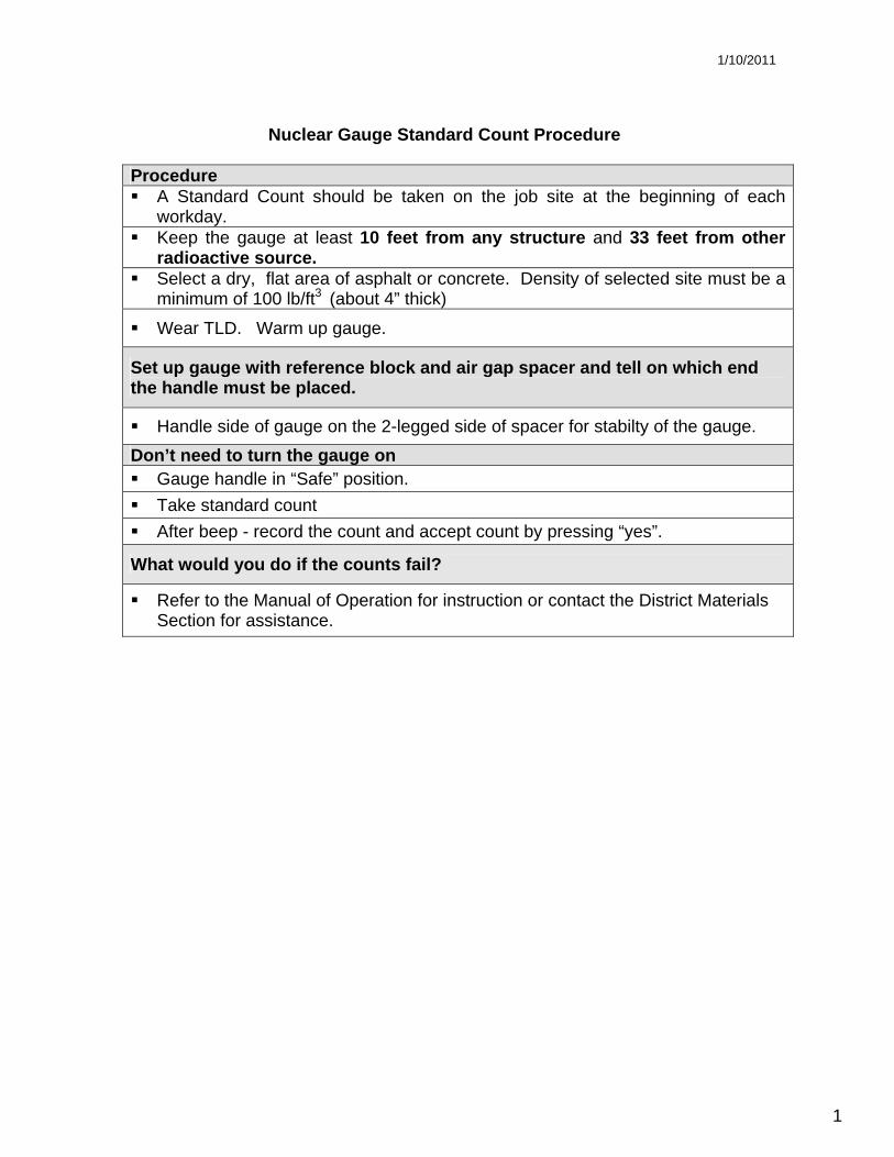
Nuclear Gauge Standard Count Procedure
Procedure A Standard Count should be taken on the job site at the beginning of each
workday. Keep the gauge at least 10 feet from any structure and 33 feet from other
radioactive source. Select a dry, flat area of asphalt or concrete. Density of selected site must be a
minimum of 100 lb/ft3 (about 4” thick)
Wear TLD. Warm up gauge.
Set up gauge with reference block and air gap spacer and tell on which end the handle must be placed.
Handle side of gauge on the 2-legged side of spacer for stabilty of the gauge. Don’t need to turn the gauge on Gauge handle in “Safe” position. Take standard count After beep - record the count and accept count by pressing “yes”.
What would you do if the counts fail?
Refer to the Manual of Operation for instruction or contact the District Materials Section for assistance.

1/10/2011
2
VTM -76 Roller Pattern What is the purpose for constructing a Roller Pattern?
Determine the number of roller passes required to achieve maximum density on an asphalt mat.
Should the paving train keep moving while constructing the Roller Pattern? No, it is recommended that the paving train stop
How much mix should be placed before constructing a Roller Pattern? A minimum of 500 feet
What makes a pass? A pass is counted each time the roller passes over the same spot.
Procedure: Use a rolling measuring device that will measure from 1 to 1000 feet or any other
measuring method approved by the Engineer.
Measure out 75 feet for Roller Pattern with additional 50 feet on either end to allow for roller positioning
If it is a mix that you have no experience with, it is recommended that you start by making two passes in vibratory mode before taking a reading.
Make 2 passes w/roller, straight up and back then move over to the other side of the lane and repeat.
Select 2 test site locations about 30 feet apart on one side of the lane and 1 test site location on the opposite side of the lane about 15 ft. from each of the first two sites
Using nuclear gauge template and approved spray paint, mark each location. Nuclear gauge should be parallel with the roadway with the source toward the paver
and no closer than 12 inches to an unsupported edge for a surface mix or intermediate mix and 18 inches for a base mix.
Take a density reading at each of the three marked locations. Gauge should be in “Test” or “Backscatter” position and 30 second mode.
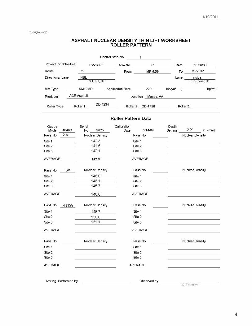
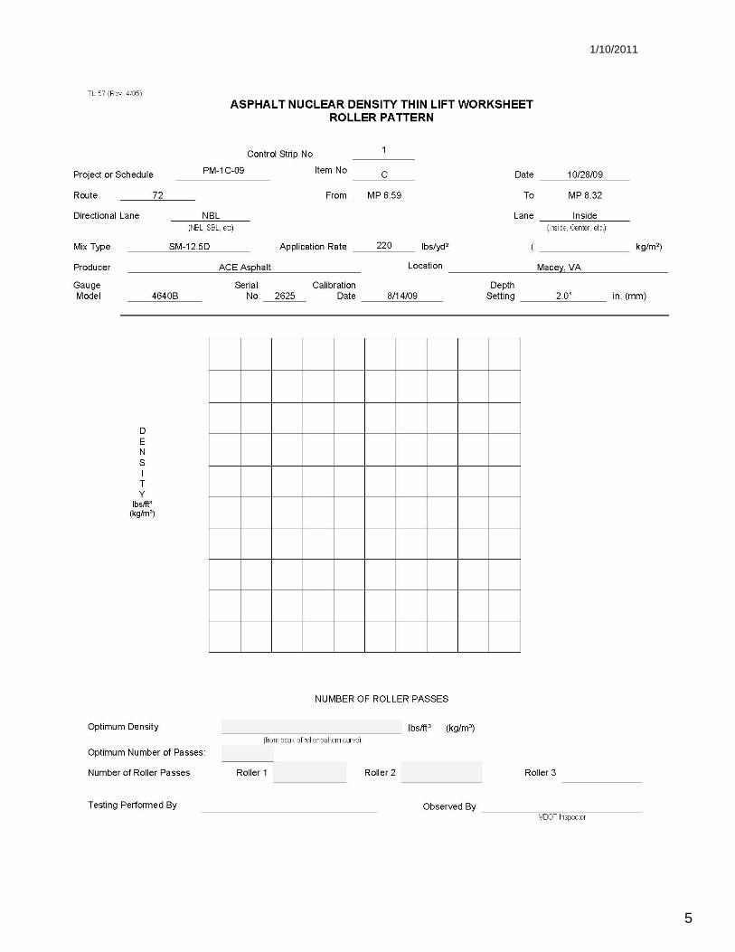
Record and average the readings from the 3 test site locations on the Roller Pattern worksheet (TL-56) and plot the density versus the number of roller passes on the Roller Pattern graph sheet (TL-57).
Continue until average density decreases. After the first decrease, make 1 additional pass to insure this was not a false break. If mat continues to decrease in density, then maximum density is density achieved one roller pass before the initial decrease in density.
1/10/2011
3
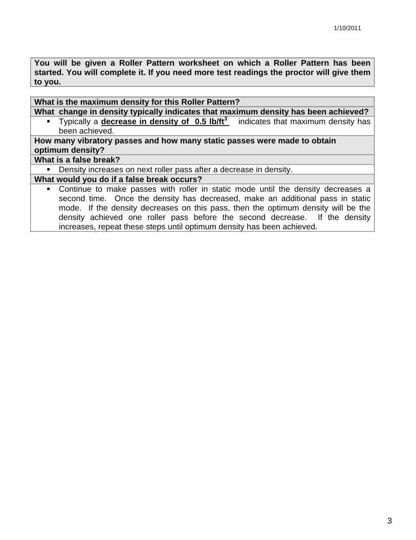
What is the maximum density for this Roller Pattern? What change in density typically indicates that maximum density has been achieved?
Typically a decrease in density of 0.5 lb/ft3 indicates that maximum density has been achieved.
How many vibratory passes and how many static passes were made to obtain optimum density? What is a false break?
Density increases on next roller pass after a decrease in density. What would you do if a false break occurs?
Continue to make passes with roller in static mode until the density decreases a second time. Once the density has decreased, make an additional pass in static mode. If the density decreases on this pass, then the optimum density will be the density achieved one roller pass before the second decrease. If the density increases, repeat these steps until optimum density has been achieved.
You will be given a Roller Pattern worksheet on which a Roller Pattern has been started. You will complete it. If you need more test readings the proctor will give them to you.
1/10/2011
4
1/10/2011
5
1/10/2011
6
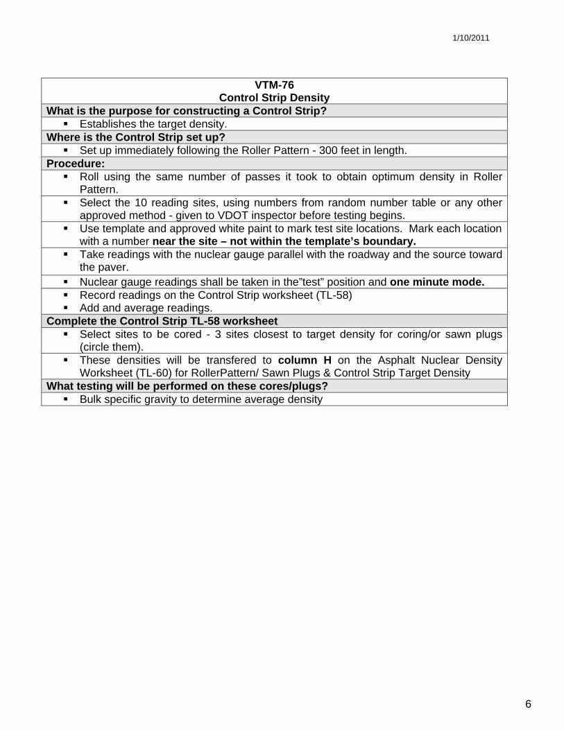
VTM-76 Control Strip Density
What is the purpose for constructing a Control Strip? Establishes the target density.
Where is the Control Strip set up? Set up immediately following the Roller Pattern - 300 feet in length.
Procedure: Roll using the same number of passes it took to obtain optimum density in Roller
Pattern. Select the 10 reading sites, using numbers from random number table or any other
approved method - given to VDOT inspector before testing begins. Use template and approved white paint to mark test site locations. Mark each location
with a number near the site – not within the template’s boundary. Take readings with the nuclear gauge parallel with the roadway and the source toward
the paver. Nuclear gauge readings shall be taken in the”test” position and one minute mode. Record readings on the Control Strip worksheet (TL-58) Add and average readings.
Complete the Control Strip TL-58 worksheet Select sites to be cored - 3 sites closest to target density for coring/or sawn plugs
(circle them). These densities will be transfered to column H on the Asphalt Nuclear Density
Worksheet (TL-60) for RollerPattern/ Sawn Plugs & Control Strip Target Density What testing will be performed on these cores/plugs?
Bulk specific gravity to determine average density

1/10/2011
7

1/10/2011
8
VTM - 22 Field Determination of Percent Density of Compacted Asphalt Concrete Mixtures Procedure
To prevent delay in density determination, cores/plugs from surface and intermediate mixes shall be cut dry. Base mixes may be either dry or wet cut.
Chill the area to be sawn with CO2 or dry ice. Using a rotary saw as specified by VDOT cut two 4 x 4 inch specimens or using a
coring machine, cut two 4 inch diameter core specimens. Chill the area again. Gently pry around core/plug to break it loose from underlying layer. Take care not to crack or break off any part of the core. Measure thickness of test specimen and record it on the worksheet (TL-60) to the
nearest 0.1 inch. What would you do if one of the cores/plugs from a site is damaged?
Discard and use the undamaged core/plug taken from the same site to represent bulk density of that site.
What would you do if both of the cores/plugs from a site are damaged? Take another set of plugs/cores from the next site whose nuclear density reading
is closest to Target Density. Go to VTM-6 and demonstrate procedure. Then complete the TL-60 worksheet Is the job-mix theoretical maximum specific gravity used for calculating sawed
average % density throughout the testing? (Point to it and formula for clarification.) No, it is determined by a moving average of 5 values. Until you have 5, it’s
based it on a simple average Is this Control Strip acceptable? Why or why not?
Determine minimum density requirements from Table III-3 of Section 315 of VDOT Rd & Bridge Specifications
1/10/2011
9
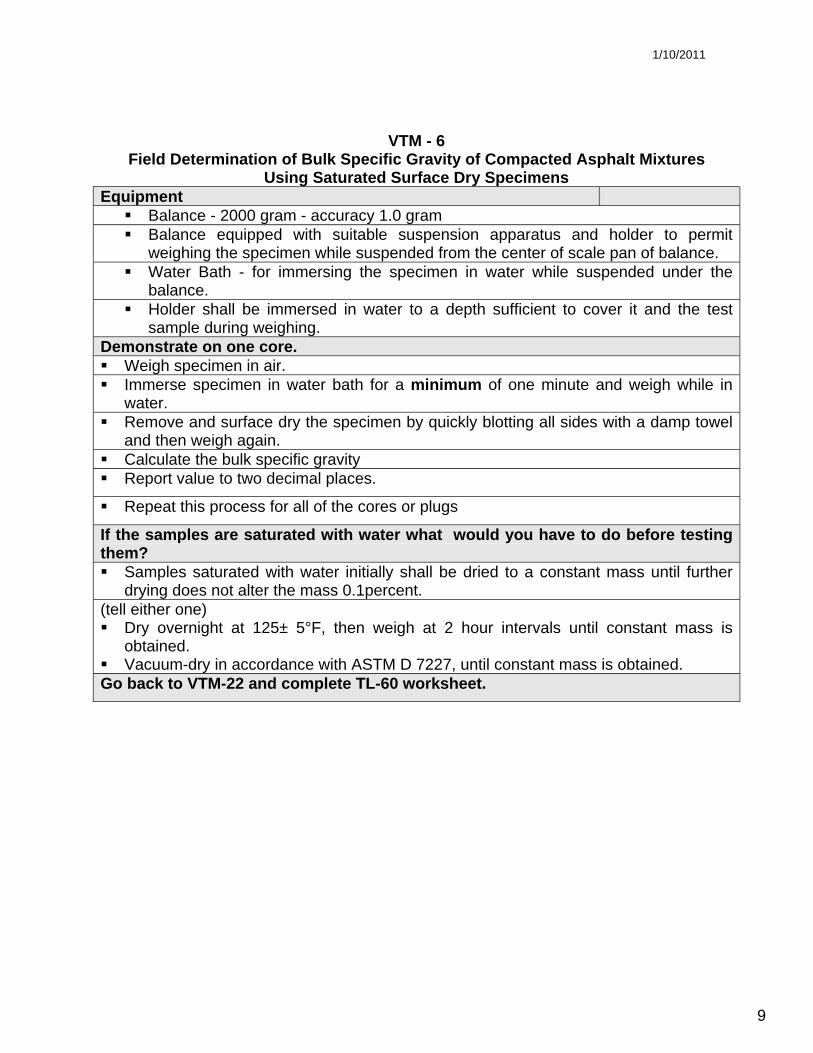
VTM - 6 Field Determination of Bulk Specific Gravity of Compacted Asphalt Mixtures
Using Saturated Surface Dry Specimens Equipment
Balance - 2000 gram - accuracy 1.0 gram Balance equipped with suitable suspension apparatus and holder to permit
weighing the specimen while suspended from the center of scale pan of balance. Water Bath - for immersing the specimen in water while suspended under the
balance. Holder shall be immersed in water to a depth sufficient to cover it and the test
sample during weighing. Demonstrate on one core. Weigh specimen in air. Immerse specimen in water bath for a minimum of one minute and weigh while in
water. Remove and surface dry the specimen by quickly blotting all sides with a damp towel
and then weigh again. Calculate the bulk specific gravity Report value to two decimal places.
Repeat this process for all of the cores or plugs
If the samples are saturated with water what would you have to do before testing them? Samples saturated with water initially shall be dried to a constant mass until further
drying does not alter the mass 0.1percent. (tell either one) Dry overnight at 125± 5°F, then weigh at 2 hour intervals until constant mass is
obtained. Vacuum-dry in accordance with ASTM D 7227, until constant mass is obtained.
Go back to VTM-22 and complete TL-60 worksheet.

1/10/2011
10
1/10/2011
11
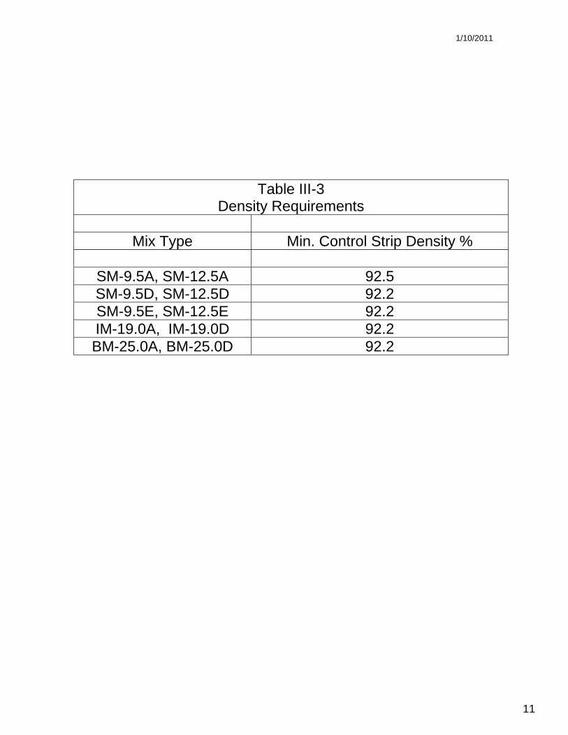
Table III-3 Density Requirements
Mix Type Min. Control Strip Density %
SM-9.5A, SM-12.5A 92.5 SM-9.5D, SM-12.5D 92.2 SM-9.5E, SM-12.5E 92.2 IM-19.0A, IM-19.0D 92.2 BM-25.0A, BM-25.0D 92.2
1/10/2011
12
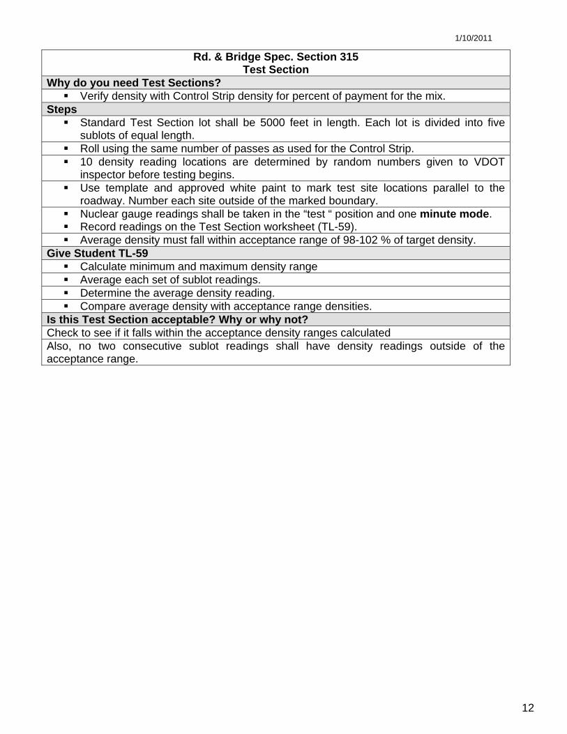
Rd. & Bridge Spec. Section 315 Test Section
Why do you need Test Sections? Verify density with Control Strip density for percent of payment for the mix.
Steps Standard Test Section lot shall be 5000 feet in length. Each lot is divided into five
sublots of equal length. Roll using the same number of passes as used for the Control Strip. 10 density reading locations are determined by random numbers given to VDOT
inspector before testing begins. Use template and approved white paint to mark test site locations parallel to the
roadway. Number each site outside of the marked boundary. Nuclear gauge readings shall be taken in the “test “ position and one minute mode. Record readings on the Test Section worksheet (TL-59). Average density must fall within acceptance range of 98-102 % of target density.
Give Student TL-59 Calculate minimum and maximum density range Average each set of sublot readings. Determine the average density reading. Compare average density with acceptance range densities.
Is this Test Section acceptable? Why or why not? Check to see if it falls within the acceptance density ranges calculated Also, no two consecutive sublot readings shall have density readings outside of the acceptance range.

1/10/2011
13