2011, quarter 3, issue 9
16
The Global quality and service system of metal working industry 2011 VOLUME 3 ISSUE 9 Quarterly The Product Global outlook Distribution Product Global outlook Distribution Australia MCG-5XM From a bold idea to a fully developed piece of engineering
-
Upload
phunghuong -
Category
Documents
-
view
212 -
download
0
Transcript of 2011, quarter 3, issue 9

The
Global quality and service system of metal working industry
2011 VOLUME 3 ISSUE 9Quarterly
The
Product
Global outlook
Distribution
Product
Global outlook
Distribution
Australia
MCG-5XM
From a bold idea to a fullydeveloped piece of engineering

HBM-4T HBM-5T CNC Boring & Milling Machine
2
3
4
6
10
12
16
18
20
29
25
From the publisher
Introduction for company- Newsroom
Global outlook-Australia
Distribution- RON MACK Machinery- Grünewald GmbH
Products - MCG-5XM R&D Zone- Thermal Error Compensation Modeling
Application
Key component- perform turning operations on all machining centres-D’andrea
FAQ- Trouble Shooting
EVENT- EMAF- BIMU
Exhibitions
of company profile, sharing Challengers' Products experience and pictures of people, products. Please send your story and pictures (images in high-resolution higher than 300 dpi ) to your Challenger Factory Outlet or e-mail to [email protected] Only English version is acceptable.
Welcome user’s submission
2011
Spindle quill diameter ( W axis ) : 130mm for HBM-4T/ HBM-5T/ HBM-5TE Taper : ISO # 50 for HBM-4T/ HBM-5T/ HBM-5TE power rated : 22KW (Fanuc) for HBM-4T, 37KW (Fanuc)forHBM-5T/ HBM-5TE X travel: 2000 (std.) /3000 (opt.)mm for HBM-4T, 3500 (std.) / 4500 (opt.) / 5500 (opt.)for HBM-5T, 3500 (std.) / 4500 (opt.) / 5500 (opt.)/6500 (opt.) for HBM-5TE Y travel: 2000mm for HBM-4T, 2600mm for HBM-5T, 4300mm for HBM-5TE Z travel : 1400mm for HBM-4T, 1400(std.)/2000(opt.)mm for HBM-5T, 2000mm for HBM-5TE W1 (std.) / W2 (opt.): 700/800 mm for HBM-4T, 700 mm for HBM-5T, 700/1000mm for HBM-5TE Table dimensions : 1400x1600 mm for HBM-4T, 1800x2200 mm for HBM-5T, 2500x2500/ 2900x4500 mm for HBM-5TE
Publisher: Paul ChangE-mail: [email protected]: Christine [email protected] board: Christine Chiu Paul Chang Sabina Chen Christine Chang
Layout and Typesetting : Treasure Map Advertising Corp.E-mail: [email protected]
Subscription:Buffalo Machinery Co., Ltd.56, Lane 318, Der Sheng Road, Ta Ya, Taichung City, TaiwanTEL : 886-4-25 60 37 59 FAX: 886-4-25 60 37 69www.buffalo.com.tw
Copyright@2011 Buffalo Machinery Co., Ltd. All right reserved. No portion of this publication covered by the copyright herein may be reproduced in any form- graphic, electronic, mechanical, photocopying without the written permission of the publisher.
Opinion expressed by contributors and advertisers are not necessarily those of the publisher or editor and take no responsibility for any false claims or erroneous information
Inde
xCh
alle
nger
201
0 V
olum
e 3
Issu
e 9
1
The Vol. 3 Iss. 9 2011
The Australia traditional ferryboat
Index
- Heidenhain iTNC 530 -Enhancement for virtual tool - Additional Operator Terminals for the TNC-IPC

From the publisher
New
sroo
mCh
alle
nger
201
1 Vo
lum
e 3
Issu
e 9
3
Newsroom
inally we can confirm that the economy is recovering and much stable than last quarter, though still some factors remain unclear or not been improved to excite most of the job shops to take further decision to put many new equipments into production. But we feel confident that the time is coming, and the reasons are as following:
01) Most of the job shops are 80%-85% busy of their job, with all improving economic fact, most of the industries are asking for more orders, soon the job shops are going to be full again, though that the oil and gas industries remain waiting.02) Most of the job shop need more updated equipments which provide an updated technology at a competitive cost, as they can’t buy any more expensive big brands. All they need are reliable equipment with updated technology and
ensure stable and high productivity. For example, the Smart Machine Technology from Microcut-Challenger is going to meet their requirement, a strong machine with smart function which make a perfect cutting and at a reasonable price level, this is all the job shops need
03) New Microcut-Challenger products provides a much stronger capacity and new CNC control concept supporting machining process, which is time saving and quality improvement. This is how we can support our customer to make a better profit. We need to make sure that all the potentials know what we are offering.
However, the prices of all the raw material soar with the rise of oil price and energy shortage. In addition to the delayed supply delivery, the cost of raw material rise around 10%~15%. The super hard currency in Asia (including NT Dollars) forces the hike in all the product prices. This is another unexpected big issue following the 2008 global financial crisis.
Bank support is still a big issue which we hope soon they will become more loose and come back to support our clients. The fact is that they need to make money and I am sure that our clients are getting more business, their finance report are improving, the time will come.
The feedback from recent exhibitions confirmed that the clients are back to ask for new equipment. Shows in Stuggart, Milan and Istanbul had been very successful to get lots of new orders, so, it is moving faster than we would expect, we need to look to the market closely. A great success to you all in the coming 2011 !
Dr. Paul Chang December, 2010
Microcut will once again presents the best quality products in the 2011 TIMTOS, taken place at TWTC, Nangang Exhibition Center from March 1 to 6, 2011. The biennial exhibition has already become a focus for international buyers, and the upcoming 15th TIMTOS is sure to be a prominent international event in the industry. After the successful turnout in 2009 and to stimulate more inspiration under the economic crisis worldwide, TIMTOS 2011 provides a vertically-integrated window on the top industry players and offering buyers unparalleled convenience. The event is estimated to provide spaces and opportunities for over 910 exhibitors, 4,500 booths and 44,500 visitors, so further interaction and exploration can be achieved through the period of March 1-6, 2011! Microcut sincerely welcome you to see the latest products and the most up-to-date technologies from Buffalo Machinery including HBM-5T with Fanuc 18i, MCG-5X with Heidenhain i TNC530, MCG-5XM with Heidenhain TNC620,Dual-500 with SIEMENS 840D SL, V-26 with Heidenhain i TNC530 & smart machine system, V-20 +4/5 AXES with Siemens 828 SL, LT52 with Fanuc 0iTD +C-axis.The main features are as below:F
Microcut Machine in TIMTOS 2011, TAIPEI, TAIWAN
HBM-5T Horizontal Boring and Milling Machine The HBM line is widely productive in power industry, transportation, mining, oil & gas industry, mold and steel construction. Both quill and ram type are available. Big capacity provided by several length 3500/4500/5500mm in X travel, 2600 or 3200mm in Y travel, 1400 or 2000mm in Z travel. Machine equipped with latest version of controllers Fanuc, Siemens or Heidenhain controller.
LT52 CNC Turning Center+ C axis The LT series displayed with a 15-hp (11-kW) spindle drive (with Fanuc Control) and Living tool, C-axis, power turret (Sauter) and parts catcher for complex parts and automatic production. LT52 features rigid cartridge type spindle, one piece 30 degree slant bed, high spindle speed, linear guide ways and compact size.
MCG-5X – High precision 5 axes control Vertical Machining Center with Heidenhan iTNC530The MCG-5X high-precision 5-axis control vertical machining center provides both superior accessibility and visibility. DDM ( Direct Drive Motor ) is applied on the A and C axes, 3-guide-way construction on Z-axis, and twin guideway with twin liner scales on Y axes, fulfilling excellent high-speed, high-precision machining.
Dual 500 – High Precision Multi-Axis Turning Center with SIEMENS 840D SLThe axis configuration of Dual 500 achieves ideal process compensated by the smart technology. The upper turret with Y-axis function allows ±40mm over the center height of the tools. Dual spindle and dual turrets application for the highest productivity and high quality production. Both Siemens and Fanuc controller are available.
V26- Smart – High Speed Machining Center with latest SMART technology systemV26-Smart is the most advanced high-speed vertical machining center. High speed in-line spindle and high power spindle motor provides the benefit of highest contour accuracy and surface quality. Latest technology SMART offers modern machining technology by inspecting errors ,improving productivity and increasing the lifetime of machine.
V-20 +4/5 AXES High Speed Vertical Machine Center High speed spindle range from 12,000 rpm to 24,000 rpm provides high productivity and super accuracy. V-20 with 4/5 axes unit will extend machining performance and fasten workpiece loading speed. High feed rates, high spindle speed, rigid machine structure. Efficient cooling system achieves accuracy of the drilling depth and milling path without any thermal deformation.
Microcut Machine in TIMTOS 2011, TAIPEI, TAIWAN
From
the
publ
ishe
rCh
alle
nger
201
1 Vo
lum
e 3
Issu
e 9
2

Global Outlook
Glo
bal O
utlo
okCh
alle
nger
201
1 Vo
lum
e 3
Issu
e 9
5
Glo
bal O
utlo
okCh
alle
nger
201
1 Vo
lum
e 3
Issu
e 9
4
Countryside
AustraliaAustralia is a stable, culturally diverse and democratic society with a skilled workforce and a strong, competitive economy. With a population of more than 22 million, Australia is the only nation to govern an entire continent. It is the earth’s largest island and the sixth-largest country in the world in land area.
A prosperous developed country, Australia is the world's thirteenth largest economy. Australia ranks highly in many international comparisons of national performance such as human development, quality of life, health care, life expectancy, public education, economic freedom and the protection of civil liberties and political rights. Australia is a member of the United Nations, G20, Commonwealth of Nations, ANZUS, OECD, APEC, Pacific Islands Forum and the World Trade Organization.
Australia’s population includes Aboriginal and Torres Strait Islander peoples and migrants from some 200 countries. Migrants have brought with them language skills and other capabilities that are valuable in today’s global economy andworkforce. Although English is the official language in Australia, more than a quarter of Australia’s labors were born overseas and almost 400 languages are spoken in homes across the country. As a result, Australia offers the familiarity of a Western business culture with a workforce capable of operating in many different business environments.
The economy grew by 1.5% during the first three quarters of 2009 - the best performance in the OECD. Unemployment, originally expected to reach 8-10%, peaked at 5.7% in late 2009 and fell to 5.3% by February 2010. As a result of an improved economy, the budget deficit is expected to peak below 4.2% of GDP and the government could return to budget surpluses as early as 2015. The Australian financial system remained resilient throughout the financial crisis and Australian banks have rebounded. During 2010, the government focuses on raising Australia's economic productivity, managing the symbiotic, but sometimes tense, economic relationship with China, passing emissions trading legislation, and dealing with other climate-related issues such as drought and devastating bushfires.
Australia is a prosperous market economy. Its main industry is service industry, which accounts for 70% of its GDP. But the agricultural and mineral exports accounted for 65% of its exports. With its abundant natural resources, large exports of wool, grain and other agricultural products and iron, coal and other minerals contribute to Australian exports. While Australia’s largest export sector is minerals and fuels, manufacturing is also a major part of the economy. Advanced manufactured items ( also known as ‘elaborately transformed manufactures’ or ETMs ), including automobile, automobile components, shipbuilding, chemical, metal and wood products, accounted for around 60% of Australia’s total manufactured exports. Many of the companies producing these goods are integrated into global supply chains, one of the key manufacturing trends of the new millennium. Australia is home to a thriving network of 470 biotechnology companies: 49% are involved in therapeutics, 15% in agricultural biotechnology and 13% in diagnostics. Excellent research facilities, world-class scientists and a strong but flexible regulatory regime have made Australia a powerhouse of biotechnology and pharmaceutical innovation. Over the past decade, Australia’s exports of ETMs, with high levels of value added, have grown at an average annual rate of 3.2%. Export successes include passenger motor vehicles to the United States, Middle East, Southeast Asia and South Africa, and full engine kits to the Republic of Korea. Australia has also developed a competitive edge in high technology exports, such as medical and scientific equipment.
A diverse people
Economy
Trade and main industries
The Great Barrier Reef is one of the 17 Australian properties on the World Heritage List. The reef contains an abundance of marine life and comprises of over 3000 individual reef systems and coral cays.
In the last century, Australia’s economic success was based onits abundant agricultural and later mineral and fuels resources.
The mining sector is expanding, driven primarily by huge demand for raw materials from Asia.
The Sydney Opera House in 2007 became the second building in Australia to achieve World Heritage listing.

Dis
tribu
tion
Chal
leng
er 2
011
Volu
me
3 Is
sue
96
Dis
tribu
tion
Chal
leng
er 2
011
Volu
me
3 Is
sue
97
Distribution
ounded in 1963 in Perth, Western Australia Ron Mack Machinery has grown from strength to strength and is now one of Australia’s premier suppliers of specialist metalwork and woodwork machinery. A privately owned Western Australian company employing 30 people, Ron Mack Machinery offers capital sales, aftermarket sales, service and training through its local offices in Western Australia and Victoria and extensive dealer network across Australia. Ron Mack Machinery is not only Australia’s longest operating supplier of metalwork and woodwork machinery, it has arguably Australia’s most experienced sales team. With over 130 years combined experience, the sales team at Ron Mack Machinery offers in-depth industry and product knowledge. Drawing on this extensive experience, the sales team at Ron Mack is able to provide the complete solution for all metalwork and woodwork operations.
Today, Ron Mack Machinery offers total sales and service solutions for the metalworking and woodworking industries, exclusively distributing innovative, functional and technologically advanced machines from Buffalo Machinery as well as many other companies around the world. Each of our dedicated showrooms displays an extensive range of machinery, from small handy-man saws to larger CNC Machines. With the ability to operate the machinery, the showrooms provide a perfect venue for customers to inspect machines under operating conditions.
“ We found that there were many companies who had a desire to keep up with the times and introduce CNC machines into their business but found the more traditional ISO programming systems of Fanuc and other similar CNC control to be unsuited to their smaller batch quantities & jobbing type work load.” said Darryl Mack, managing director of Ron Mack machinery. “One of the main features that greatly appealed to our customers was the ease of programming using the conversational systems of Fagor and Siemens. Our turn key service not only included installation and excellent after sales service but within 4 days of training after the machine installation.” “ It was possible for any operator with experience of conventional machining operating the new CNC machine to almost 100% capacity.” commented Tim, manager of Ron Mack. This also appealed to the customers because of thehigh salaries demanded by established CNC operators and
their lack of availability during the recent boom times experienced in the Australian market. It is now easy to train a new CNC operator in house and the need should arise.
“Buffalo’s ever expanding range of machines has also opened up many new potential customers for us”, said Darryl. “Especially with the introduction of the CNC Boring Machines and the larger BNC Lathes, a large sector of Australian industry consists of remanufacture and repair which is heavily influenced by the mining industry and mining related products which are getting bigger and bigger all the time.” Being able to offer customers reliable machines at affordable prices with the best technical support is so important in the competitive machine tool sales market today. “We can always find a complete selection from Buffalo Machinery.” stated Darryl.
Ron Mack -Continuous improvement in all aspects of day to day business
F
With the introduction of the CNC Bori ng Machines and the larger BNC Lathes, a large sector of Australian industry consists of remanufacture and repair which is heavily influenced by the mining industry and mining related products.
With the ability to operate the machinery, the showrooms provide a perfect venue for customers to inspect machines under operating conditions.
Ron Mack Machinery is also one of the few suppliers of metalwork and woodwork machinery in Australia to operate a full in-house service department. Consisting of one manager and five service technicians, the service team provides commissioning, service and training for the complete range of metalwork and woodwork machinery. All service technicianshave extensive experience in the metalwork and woodwork industries and partake in continual internal and external professional training.
During a business trip to Taiwan in 1984 Ron Mack Managing Director, Mr Darryl Mack was introduced to Paul Chang and a business relationship was formed between the two companies. Since that meeting Ron Mack has purchased hundreds of Microcut Turret Mills and Conventional Lathes forging a strong business relationship between the two companies.
In 1996, Ron Mack Machinery made an effort to establish a stronger market share of CNC Machines in the Australian Market and this has grown rapidly. A large proportion of this success has been due to the working relationship with Buffalo Machinery. With the introduction of Fagor and Siemens conversational programming systems, a whole new market was established with many smaller general engineering companies lacking exposure to CNC machining.

Mr. Michael Wolf, the CEO of company Grünewald (Left) and Mr. Dirk Husemann, sales for milling and turning machines from company Volz.(right)D
istri
butio
nCh
alle
nger
201
1 Vo
lum
e 3
Issu
e 9
8
Dis
tribu
tion
Chal
leng
er 2
011
Volu
me
3 Is
sue
99
Distribution
From a bold idea to a fully developed piece of engineering
ound in 1976 in Remscheid, Germany , Grünewald GmbH is renowned for its standard of high quality and continuous development in the field of control and measuring engineering.In milling and turning of the medium-sized measuring and control technology manufacturer Grünewald relies exclusively on CNC machines of the trading house Volz, because they are easy to program on site and can respond as flexibly within the production.
"If we want to be successful, we need to respond flexibly to market changes, including short lead times and high manufacturing quality at marketable prices", said Michael Wolf, CEO of Grünewald GmbH in Hamm.
The company manufactures explosion-proof measuring and control instruments for flow, temperature, pressure and level measurement and control systems. A specialty of the company is measuring and monitoring systems for the coal-mining. "There are only two market-related companies in Germany, one of which we are," says Mr. Wolf.
The portfolio of the company includes some 460 different instrumentation and control equipment. Produced almost all materials which are not electrostatically chargeable, for example steel, stainless steel, nonferrous metals. The lot sizes
are between 10 and 100. The number of repeated parts is very large.
The required processing capabilities to move within a tolerance range H7 and H8. The repeatability is 0.05 mm, the required surface quality of sealing surfaces to Ra = 0.8 microns. "The absolute tightness of the explosion-proof measuring and control devices in the mining industry is an essential criterion," says Mr. Wolf.
Grünewald GmbH, renowned in the field of control and measuring engineering,distributes Germany manufactured products worldwide.
With six Challenger machine tools work in mechanical production, the lot sizes are between 10 and 100.
F
CNC machines for many materials
Challenger machining centers and lathes in the production
Products made on Challenger machines:
In the mechanical manufacturing, the company Grünewald produced exclusively on Challenger machining centers and lathes of the Witten trading house Volz. In 2006, Grünwald invested its first Challenger machine, a vertical machining center Typ: Micromill-Challenger MCV 2418, to replace a conventional milling machine, which no longer fulfilled the requirements for performance and accuracy. "Without CNC machines nowadays instruments are no longer economical to produce," said Wolf.
Already one years later the company bought another Challenger machining center. Shortly afterwards a large CNC lathe „ Challenger Microturn BNC 2260. The youngest member in the "production team" is the last year bought small Challenger Microturn BNC 1640 S.
Meanwhile six machines from Volz are working in the mechanical manufacturing. What is the reason of these suppliers loyalty? “ The key for our decision to choose this machines was the good price / performance balance of the Challenger machines, " says Mr. Wolf's and “ also these machines fulfill our requirements in all respects, including the process reliability and repeatability. For a small medium-sized company like ours, the machines are just the right choice."
This " monoculture " in milling and turning brings other advantages, says the salesman of the company Volz Mr. Dirk Husemann: "The total cost of repair and maintenance is lower than a company with many different machining centers from various manufactures and employees have the flexibility without additional training required be used on the various machines." Both company Volz and Grünewald praise the many years of good cooperation with each other.
Lathes and machining centers from a single source to reduce maintenance costs

Pro
duct
Chal
leng
er 2
011
Volu
me
3 Is
sue
910
Pro
duct
Chal
leng
er 2
011
Volu
me
3 Is
sue
911
Product
t is awarded that a quality 5 axis machining center will provide lots of advantages to improve the machining cost and accuracy of the products. Together with its 5 axes simultaneously machining capability, high ACC/DEC time, high removable rate and high CNC performance quality, a Gantry type design to be equipped with rigid high torque CNC Tilting Rotary Table, such as Challenger MCG-5X provided with workpiece capacity of 1200 kg (2640lbs). A wide range of products can be machined by this model, which is fast working speed due to its high removable rate. Its high accuracy is a result of strong machine structure design, well consideration of heat deformation and a smart machine technology package in this model. The machine quality can provide a machining shop a money making machine. The enlarged magazine will be able to load up to max 96 tools (120 tools on special request) which meet wide range of application.
Adding to the heavy duty loading capacity, a large movement of its X/Y/Z axis, 670X820X600 mm, providing a wide range of working capacity, ensuring the machine meet the requirement of most middle & small size parts for aero space, wind mills, automobile and mold industries. Adding to model MCG-5X, a smaller working capacity 5 axis machining will be announced in the coming TIMTOS 2011. Model MCG-5XM is providing working range with 3-axis travel for 600X550X500 mm and the table load is up to 600 kg. A rigid Ram and semi Gantry design will offer a powerful cutting capacity for smaller and lighter working piece. With its superior design, the machine is ensuring a minimum space requirement, high stability, continuous accuracy and a powerful milling performance. And yet, the machine performs 5 axes simultaneous cutting features. The machine MCG-5XM is equipped with Heidenhain iTNC530, Siemens 840D solution line or Fanuc 31 iMC.
I5 axes or 5 face machining?
MCG-5XM
Gantry type structure is well-known as a better rigid design for better job life.But it takes always much bigger space which does not fit to all the potential.An updated design which is the mixture of semi-Gantry and Ram, ensuring the wide working capacity and rigidity. A torque motor driver table can ensure perfect accuracy and finish which 5-axis simultaneously milling is applied.Well-designed chip removal device , powerful spindle and all axis feed motor provide strong power and torque for high speed machining.
Fig.1 Example of application:
R&
D Z
one
Chal
leng
er 2
011
Volu
me
3 Is
sue
912
R&
D Z
one
Chal
leng
er 2
011
Volu
me
3 Is
sue
913
R&D ZONE
High speed machining technique has been the most important application in the metal cutting and machining industries. However, to overcome the positioning error from thermal effect and the improvement of compensation technique have become a great concern of study. A thermal imaging camera is used in this paper to confirm the thermal position and a temperature sensor is placed on the heat source to monitor the thermal variation for compensation reference. This paper uses the real time temperature of transmission part and the temperature variation of the monitoring points to be theinput parameters of multiple regression model which wasdifferent from traditional model considering only temperature and temperature variation. Meanwhile, this model compensates the thermal deformation under situation with linear encoder and ensures higher position accuracy.The coefficient of determination is used as the best index of variables selection. The original parameters are reduced from ten to six, saving the memory space for calculating and speeding the process of algorithm. The model improves the machining accuracy and meets the requirement of high speed machining(HSM).
Abstract
With the development of cutter and machine tool manufacturing technology, the high removal rate and high precision cutting technique have replaced the traditional cutting method which features low spindle speed, low feed rate and deep cutting. The high speed machining center, with the combination of high cutting speed, high axial feed rate and high CPU processing speed, can increase the competitiveness by improving machining efficiency and reducing machining cost. HSM technology has been widely applied on aerospace, high speed mold, electrical and automobiles industries. Nevertheless, researchers also need to overcome the problems coming from high speed machining , such as the heat generated from high cutting speed and high feed rate. The heat on machine body will cause the thermal error and positioning error which reduce the machining accuracy. The thermal error accounts for 50% of total machining error. The positioning error caused by the thermal displacement of transmission parts can be reduced by equipping with linear encoder and mechanical improvement for heat dissipation and software compensation. The mechanical improvement reduces the temperature by thermal suppression and thermal stabilizer design. A hollow screw with cooling system is commonly used to cool the screw temperature. Besides, the thermal distortion stabilizing system designed by YASDA is used to keep the machine temperature about ± 0.2 to the room temperature.
Those mechanisms can reduce the positioning error to someextent. However, despite the linear encoder is widely used, it also increases the cost of machine tool and is limited by heat. As the linear encoder equipped on the working table, its positioning precision will be affected by the thermal deformation of the working table under fluctuation in ambient temperature.
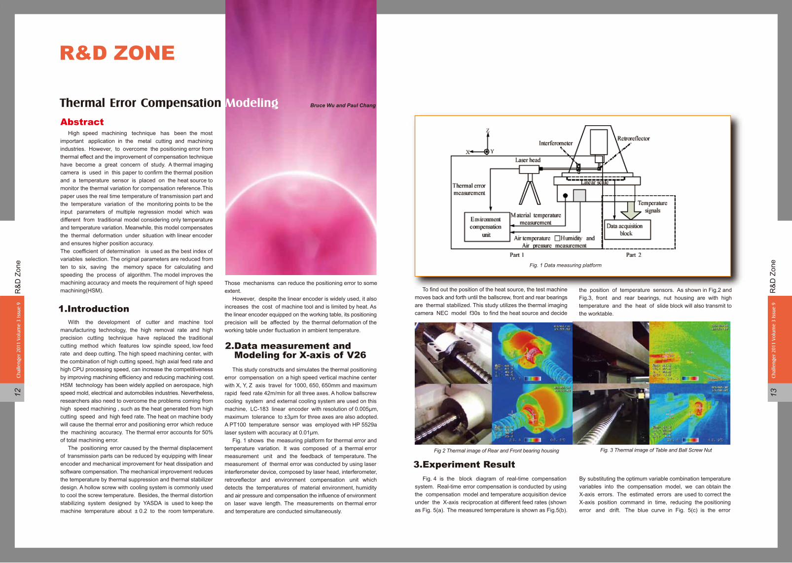
This study constructs and simulates the thermal positioning error compensation on a high speed vertical machine center with X, Y, Z axis travel for 1000, 650, 650mm and maximum rapid feed rate 42m/min for all three axes. A hollow ballscrew cooling system and external cooling system are used on this machine, LC-183 linear encoder with resolution of 0.005μm, maximum tolerance to ±3μm for three axes are also adopted. A PT100 temperature sensor was employed with HP 5529a laser system with accuracy at 0.01μm. Fig. 1 shows the measuring platform for thermal error and temperature variation. It was composed of a thermal error measurement unit and the feedback of temperature. The measurement of thermal error was conducted by using laser interferometer device, composed by laser head, interferometer, retroreflector and environment compensation unit which detects the temperatures of material environment, humidity and air pressure and compensation the influence of environment on laser wave length. The measurements on thermal error and temperature are conducted simultaneously.
1.Introduction
2.Data measurement and Modeling for X-axis of V26
Fig. 1 Data measuring platform
To find out the position of the heat source, the test machine moves back and forth until the ballscrew, front and rear bearings are thermal stabilized. This study utilizes the thermal imaging camera NEC model f30s to find the heat source and decide
the position of temperature sensors. As shown in Fig.2 and Fig.3, front and rear bearings, nut housing are with high temperature and the heat of slide block will also transmit to the worktable.
Fig 2 Thermal image of Rear and Front bearing housing Fig. 3 Thermal image of Table and Ball Screw Nut
Fig. 4 is the block diagram of real-time compensation system. Real-time error compensation is conducted by using the compensation model and temperature acquisition device under the X-axis reciprocation at different feed rates (shown as Fig. 5(a). The measured temperature is shown as Fig.5(b).
By substituting the optimum variable combination temperature variables into the compensation model, we can obtain the X-axis errors. The estimated errors are used to correct the X-axis position command in time, reducing the positioning error and drift. The blue curve in Fig. 5(c) is the error
3.Experiment Result
Bruce Wu and Paul ChangThermal Error Compensation Modeling

R&
D Z
one
Chal
leng
er 2
011
Volu
me
3 Is
sue
914
Chal
leng
er 2
011
Volu
me
3 Is
sue
915
R&D ZONE
compensation value and the green curve is the errormeasured by laser interferometer device which is the residualerror after correction. From Fig. 5(c), the compensation systemin this research can effectively reduce the positioning error from 20μm to 3μm, improving by 85%. The machine tested in this experiment is equipped with linear scale on X-axis to compensate the position signals. It can improve the machining accuracy more substantially than current machine which is compensated by signals of motor encoder.
Compensating the temperature data real-timely by temperature acquisition device and substituting into the mathematical model established from these variables, this study corrects the positioning errors caused by thermal rise successfully. From the experiment results, the maximum error can be reduced from 20μm to 3μm and the compensation rate is 85% after installing the high accuracy linear scale.
Fig. 4 Block diagram of real-time compensation system
(a)
(b) (c)
Fig. 5 Compensation data: (a) feed rate command (b) measured temperature data (c) compensation value of X-axis and measured value
The proposed temperature variables selection and modeling method has proved to be effective for the application of thermal error compensation. From the present result, one draw the important engineering conclusions:1. This study has successfully achieved real-time compensation on vertical machine tool by using Multiple Regression Model.2. The position of thermal resources was found by thermal imaging camera and temperature sensors were utilized to
get temperature data feedback from these heat resources. Then find the optimum variable combination by calculating the max{R2}, and the determination function reduces the input variables from ten to six, saving the memory space for calculating and speeding the process of algorithm.3. From the experiment results, the maximum error can be reduced from 20μm to 3μm and the compensation rate is 85% after installing the high accuracy linear scale.
[1] J. Ni, CNC machine accuracy enhancement through real-time error compensation. Journal of Manufacturing Scienceand Engineering 119 (1997) 717–725.[2] M.Weck, P.Mckeown, R.Bonse, U. Herbst, Reduction and compensation of thermal errors in machine tools, Annals of the CIRP 44 (2) (1995) pp. 589–598.[3] http: //www.yasda.co. jp/la_English/coreTechnology/coreTechnology.htm[4]. Y. Kakino, K. Mori, A study of compensation of thermal displacement of the ball screw in NC machine tools, Journal of the JSPE (54) (1988) 1753–1758.[5] I.Alejandre, M. Artes, Thermal non - linear behaviour in optical linear encoders, International Journal of Machine Tools and Manufacture 46 (2006) 1319–1325[6] S. C. Huang, Analysis of a Model to Forecast Thermal Deformation of Ball Screw Feed Drive Systems, International Journal of Machine Tools and Manufacture 35 (8) (1995) 1099–1104[7] C.- H. Lo, J. Yuan, J. Ni, Optimal temperature variable selection by grouping approach for thermal error modeling and compensation, International Journal of Machine Tools and Manufacture 39 (1999) 1383–1396[8] J.Yang, J.Yuan, J.Ni,Thermal error mode analysis and robust modeling for error compensation on a CNC turning center, International Journal of Machine Tools and Manufacture 39 (1999) 1367–1381.
[9] J.S. Chen, G. Chiou, Quick testing and modeling of thermally induced errors of CNC machine tools, International Journal of Machine Tools and Manufacture 35 (7) (1995) 1063–1074.[10] M. Weck, U. Herbst. Compensation for the thermal errors in machine tools with a minimum number of temperature probes based on neural networks, ASME Annual Meeting (1998) 45–53. [11] K. C. Wang, P. C. Tesng, K. M. Lin, Thermal Error Modeling of a Machining Center using Grey System Theory and Adaptive Network- Based Fuzzy Inference System, , Journal of the JSME 49 (4) (2006) [12] D. S. Lee a, J. Y. Choi, D. H. Choi, ICA based thermal source extraction and thermal distortion compensation method for a machine tool, International Journal of Machine Tools and Manufacture 43 (2003) 589–597[13]E. Creighton, A. Honegger, A. Tulsian, D. Mukhopadhyay, Analysis of thermal errors in a high-speed micro-milling spindle, International Journal of Machine Tools and Manufacture 50 (2010) 386–393[14]A. C. Okafor, Y. M. Ertekin, Vertical machining center accuracy characterization using laser interferometer: Part 1. Linear positional errors, Journal of Materials Processing Technology 105 (2000) 394-406
4.Conclusion
Reference

HEIDENHAIN iTNC 530
Enhancement for Virtual Tool
Application
ApplicationThe virtual tool axis function is also possible in combination with heads without measurement system
Availability�• NC software 340 49x-067�• NC software 606 42x-01 (HSCI)
App
licat
ion
Chal
leng
er 2
011
Volu
me
3 Is
sue
917
App
licat
ion
Chal
leng
er 2
011
Volu
me
3 Is
sue
916
IPC 6110 – Industrial PC with TNC FunctionalityIPC 6110 – Industrial PC
Operating system: Windows XP EmbeddedCompact designSimple cable connection to the controlSimple configuration of the connection to the controlthrough HEIDENHAIN-specific “TNCterminal” softwareSimple operation possibilities for tool magazines, palletchangers and additional machine software(e.g. maintenance program*)Modified TNC Keyboard for operationPre-installed “TNCremo” data-transmission software,USB port next to the screen *must be tested on IPC 61xx before customer release
Additional Operator Terminals for the TNC-IPC
FunctionTo calculate an offset in the current tool axis direction you can enter a value for the direction of VT in function M114.
■■■■
■
■■
TNC terminal 2.0–Software for Remote TNC Operation
IPC 6120 – Industrial PC
*must be tested on IPC 61xx before customer release
■■■■
■
■
■
Operating system: Windows XP EmbeddedCompact designSimple cable connection to the controlSimple configuration of the connection to the controlthrough HEIDENHAIN-specific “TNCterminal” softwareSimple operation possibilities for tool magazines, palletchangers and additional machine software(e.g. maintenance program*)Can be used as a full-fledged second operating panel forthe control from a second location on the machine(exception: override potentiometers- > via analog inputs)Pre-installed “TNCremo” data-transmission software,USB port next to the screen
IPC 6120 – Industrial PC as Second Operating Station

Key
Com
pone
ntCh
alle
nger
201
1 Vo
lum
e 3
Issu
e 9
18
Key ComponentPerform turning operations on all machining centres-D’andrea
TA-CENTER boring and facing heads are made to be used on automatic tool changers, therefore on essentially all machining centres. A U-DRIVE unit commands the feed control of the tool slide and the tool placement even during rotation. This unit is managed directly by an axle called “U” by the CNC of the machining centre. Organized in this way, the machining centre is the solution to a series of different processes like inner and outer turning operations, grooves,conical and variable boring, concave and convex radius machining, cylindrical and conical threading, complex profiles, etc.
Any application on machines that do not permit the connection to an axis of the CNC, may be made by managing the motor of the U-DRIVE with a practical, simple, and economical U-CONTROL positioner with wireless REMOTE-CONTROL. The positioner can be connected to the M function of the machine to receive start signals of the various operations programmed on the REMOTE-CONTROL. Spherical machining is not possible with machines equipped with the U-CONTROL WIRELESS KIT.
Coolant exits from the two adjustable nozzles in the TA-CENTER located next to the slide after crossing the taper and the rotating body of the head. This noteworthy advantage ensures longer duration of the insert, quicker cutting speed and for obtaining good surface finishes. The centralized supply of coolant does not harm the TA-CENTER of which the internal labyrinth protected by an O-ring. It is advisable to not exceed 40 BAR of pressure.
TA-CENTER heads are designed with two counter-weights (5) for automatic balancing, that move opposite to the slide (3) allowing to machine at a higher number of rpms without noticeable oscillations.
Key
Com
pone
ntCh
alle
nger
201
1 Vo
lum
e 3
Issu
e 9
19
Coolant supply
Application on a vertical machine
Application on a horizontal machine
Balancing

FAQ
Ch
alle
nger
201
1 Vo
lum
e 3
Issu
e 9
21
FAQ
Ch
alle
nger
201
1 Vo
lum
e 3
Issu
e 9
20
Trouble shooting
On my Microcut HBM-4 machine with Heidenhain controller, the ATC arm suddenly stopped while executing tool change. As shown in following photo (see Fig. 1), while performing “TOOL CALL T0” to change tool under automatic mode, the arm suddenly stopped after extracting the tool T1 from the spindle. How can I solve the problem?
You have to return the ATC to normal condition first and then check the tool change position. The ATC problem can be solved by the following procedures:
Fig.1
Fig.2
1.Return the ATC to normal condition:1) Select “manual mode” (see A in Fig. 2) and press “MOD” key (see B in Fig.2) to display “MOD Function Key” on the control panel.
2)Press the soft key “HELP” to display “tool change service mode”.
3)Use arrow key to select service function #414 “TC arm from Spindle to basic pos” ( see Fig.3, mark in red ) and press “cycle start” button ( see Fig.4, mark in red ). Move the arm about 300mm leftward so that the gyration radius of the arm would not interfere with the spindle.
4)Execute #420 “TC to CW end position” or #421 (see Fig. 5) “TC to CCW end position” to rotate the arm to horizontal position (see Fig. 6).
BA
5)Execute #414 “TC arm from Spindle to basic pos” to move the arm to the basic position (see Fig.7).
6)Execute #410 “Magazine turn CW” or #411 “Magazine turn CCW” to rotate the tool magazine until the actual pocket number equals arm tool number.7)elect #424 “Arm tool number reset” and press “NC Start” button (see Fig.8, marked in red).
Fig.7
Fig.9
Ensure that the correct tool number of the arm is displayed on the operational screen. ( see Fig. 9)
Fig.3
Q:
A:
Fig.5
Fig.6
Fig.8
Fig.4

FAQ
Ch
alle
nger
201
1 Vo
lum
e 3
Issu
e 9
23
FAQ
Ch
alle
nger
201
1 Vo
lum
e 3
Issu
e 9
22
Trouble shooting
8)Press the soft keys “TOOL TABLE”, then “POCKET TABLE” , and “EDIT ON” (see Fig. 10, marked in red).
9)Press the soft key “RESET POCKET TABLE” (see Fig. 11, marked in red).
Fig.10
Fig.11
10)Check if the tool numbers of “P” (Pocket) and “T” (Tool) are correct (see Fig. 12, marked in red). “P0” stands for the tool clamped on the spindle. The ATC of this machine is not randomly selected, but selected one by one. Therefore, the tool number must correspond with the tool pocket. Press “ENT” button on the control panel (see Fig. 13, marked in red ) after the tool numbers are confirmed correct.
Fig.12
Fig.13
4)Select #401 “S to tool change position” and press “NC Start” to rotate the spindle to the tool change position. Take off one positioning key near ATC on the spindle (see Fig.15, marked in red).
5)Select #402 “W to tool change position” and press “NC Start” to move the W-axis to the tool change position.6)Select #405 “Tool unclamping”and press “NC Start”. Put the 3-section tool gauge into the spindle and execute #406 “Tool clamping” (see Fig. 16, marked in red).
9)Remove the shaft of the 3-section gauge (see Fig.18) and leave the center piece (V-groove block) and shank attached to the gripper and the spindle respectively.
10)Make sure if the inside holes of the center piece and shank are in the same line (see Fig.19). Adjust the Y-axis when the heights are not at the same level, or adjust the bolts of the tool arm base (see Fig. 20, marked in red) when the left/right ends are different in height, or adjust the W-axis when the front/rear ends differ in height. The Y-axis and W-axis can be adjusted by hand wheel carefully. When adjusting the bolts of the tool arm base, tighten or loosen the 2 bolts at the same time.
7)Select #404 “ Y to tool change position” and press “NC Start” to remove the Y-axis to the tool change position.8)Select #417 “TC arm from basic to spindle pos” and press“NC Start”. Jogging the arm toward the 3-section tool gauge till the arm can hold the V-groove block of the tool gauge (see Fig. 17).
1)Prepare a 3-section tool gauge (see Fig. 14).
2)Select “manual mode” and press “MOD” key to display “MOD Function Key” on the control panel. 3)Press the soft key “HELP” to display “tool change service mode”.
2.Check the tool change position:
Fig.17
Fig.14
Fig.18
Fig.15
Fig.16

FAQ
Ch
alle
nger
201
1 Vo
lum
e 3
Issu
e 9
24
Fig.19
Fig.20
Fig.23
Fig.21
11)Insert the shaft of the 3-section gauge back to the holes (see Fig. 21). This must be done smoothly; otherwise it is necessary to make the adjustment described in previous step until it can be inserted smoothly.
12)After the tool change position is confirmed correct, input the tool change position by below steps. a. Select “manual mode” (see A in Fig. 22 ) and press “program edit” key (see B in Fig. 22). b. Press MOD key (see C in Fig. 22).
c.Please key in password: 95148 (Machine Parameter).d.Go to MP4210.12 (Y axis automatic tool change position).e.Go to MP4230.29 (W axis automatic tool change position).f. Go to MP4210.14 ( Z axis automatic tool change position).g.Go to MP4210.17 (Y axis manual tool change position).h.Go to MP4230.28 (W axis manual tool change position).i. Go to MP4210.18 (Z axis manual tool change position).j. Press end key (see Fig. 23, marked in red) to exist.
Fig.22
AB
C
Trouble shooting
EV
EN
TCh
alle
nger
201
1 Vo
lum
e 3
Issu
e 9
25
EVENT
is a unique event and industrial exhibition in Portugal, where industry’s greatest supply and demand opportunities from both Portugal and abroad can be seen. During 10 to 13th November, agents and main buyers are attracted to come and view the quality, technology, innovation and R&D of products and services on display. This event shows the true importance of the industry in the global economy and determines who the best players of the sector are.
EMAF is already a point of reference and success in the industrial sector of business-to-business. It provides the ideal occasion for companies in the sector to showcase their latest products, and finding out the constant challenges and changes. The exhibition in 2010 guaranteed quality and business opportunities for exhibitors and visitors.Microcut was again at the top of the highest technology offer for machine-tools, presented by company MATER, one of the leading companies in Europe and a long date partner for Portugal.
EMAF
“MCG-5X was the biggest star in EMAF 2010. It was a very nice presence for Microcut, as no other supplier presented so many machines in working conditions. We believe it creates business opportunities as we expected. ” said Luis Moreira, CEO of Mater company.

EV
EN
TCh
alle
nger
201
1 Vo
lum
e 3
Issu
e 9
27
EV
EN
TCh
alle
nger
201
1 Vo
lum
e 3
Issu
e 9
26
Buffalo Machinery cooperates with the official Italian distributor TECNOR MACCHINE for this exhibition, presenting the advanced function and machines of Microcut/ Challenger. In BIMU, the exhibition space is 396SQM and showcased the machines as below:
successfully introduced to universal market and more functions were applied, like servo facing head is officially announced in BIMU this year. The SMART technology, SVS( spindle vibration supervision ) function, and lifter device are all completed tested.
The product line of HBM series in Buffalo, included HBM-4/ HBM-4T / HBM-5T and HBM-5TE. HBM-5T has been
In this high speed machining center with SMART Technology Function, its one-step cutting, fine cutting surface/ high accuracy and faster cutting processing time got very good response from all visitors.
A 5 axes simultaneous machining center, visitors are impressive by its high accuracy performance. A perfect cutting result has been showcased, the tolerance for gear machining shows 0.01mm tolerance which is incredible, said one of application engineer.
EVENT
T-Type CNC Boring Machine w/Fanuc 31iA controllerHBM-5T
V-26 High Speed Machining Center w/ Heidenhain iTNC530 controller
MCG-5X 5 Axes Machining Center w/Heidenhain iTNC530 controller
Dual 500 Twin Spindle & Twin Turret CNC Lathe and Fanuc 18iTC controller With the latest technical improvement, Dual 500 highlighted on High-tech and high-speed machining, its multiple axes application and as a right product for automotive industry, the high efficiency catch many eyes. The Dual model series will be developed to have bar capacity at 42/ 65/ 80mm. Those machines show good image for visitors, rigid construction, automatic turret, built-in spindle…etc, all composing a high-tech model.
Sharing the booth with TECNOR MACCHINE, the booth is always full of visitors during the show. And 15 distributors worldwide came and shared their comment and market information. “We appreciate it. We can see the slow market recovery from the market information, better than 6 months ago but some areas still remain slow.” said Paul.
“ However, we’re still confidence that the customers who visited Microcut / Challenger booth in BIMU 2010 were all satisfied with our products and service support. We’ll continuously develop new products based on comments from customers.”said Sarah.
Next appointment with BI-MU/SFORTEC is from 2 to 6 October 2012. We expect to see all of you again.
eformation and extracting machine tools, robots, automation and ancillary technologies: BI-MU is the sector showcase and benchmark for the entire manufacturing industry, offering updated design and construction of products. Hosted by the state-of-the-art structures of Fieramilano, from 5 to 9 October 2010, 27.BI-MU/SFORTEC presented the most advanced international proposals concerning: metal forming and metal cutting machines, robots, automation and auxiliary technologies. Besides SFORTEC, for this edition, the BIMU also presented specialized reviews of the most recent technological solutions for welding, surface finishing, assembling and moulding/press-forging. Microcut/ Challenger had been exhibited for 5 days in BIMU located in Fiera Milano, Italy. BIMU fair is one of the most important international machine tools show and the performance is the important index for metal cutting industry as well. The result from last BIMU hosted in 2008, there are 1702 firms, total display area is about 70,000SQM, 80 firms fromTaiwan. In Europe market, Taiwanese Machine Tools is important as the number 3 large exporter, the products included not only machines, but also accessories. This is the second biggest professional machine tools show in Europe expect EMO, the scope is bigger than METAV (Germany) and JIMTOF (Japan).
DSarah Chen

ExhibitionsDistribution companyTitle of Exhibition / CountryPeriod2011 Q1/Q2
January
March
April
May
June
20-26 M/s TechtronicsIMTEX 2011 / India
1-6 Buffalo MachineryTIMTOS 2011 / Taiwan1-3 FAMAExpo Manufactura / Mexico1-4 VolzINTEC / Germany
22-25 Lemvigh-MullerVærktøjsmaskiner 2011 / Denmark
12-16 TERNACIMT / China12-15 CADNEXFORMA TOOL / France
23-28 MEGGATONFEIMAFE / Brazil
24-27 James Machinery Pty.,Ltd.AUSTECH / AustraliaLegere industrialLEGERE OPEN HOUSE / CanadaMondaileOpen House / Belgium
7-11 DimasoldaMAQUITEC-2011 / Spain
Various suitable applications • Die and mold market• Automobile industry• Medical industry• General workshop
High Productivity • High speed processing time with Heidenhain iTNC 530- Direct driven spindle 15,000 rpm (optional built-in spindle up to 24.000 rpm)• 48 M/min rapid traverse (V-26, V-30 models)- Refrigerated ballscrews for higher accuracy• Fast tool to tool changes time (2 seconds)
High Reliability• 45mm roller type linear guide way for V-26/30• 35mm (Z axis), 30mm (X & Y axis) roller type linear guide way for V-20 and V-22• 720mm Y axis guide ways distance for V-26/30, & 480mm for V-20 and V-22• Precision ground class C3 ballscrew double nuts with oil cooler- Rigid basement stress relieved for better performances- Direct measuring in all axes
CHALLENGER HIGH ACCURACY MACHINING
CHALLENGER HIGH ACCURACY MACHINING
Chal
leng
er 2
010
Vol
ume
2 Is
sue
628
V SERIESHIGH SPEED VERTICALMACHINING CENTERS
1-4 BPKSiberian Industrial Forum / Russia9-11 BPKPromexpo-2011 / Russia
12-14 BPKMetalloobrabotka. / Russia
18-20 BPKPOWER-KAZINDUSTRY-2011 / Russia23-27 BPKMetalloobrabotka 2011 / Russia
16-18 BPKPromTechExpo-2011 / Russia
21-24 BPKMachinery. Machines. Tools / Russia