
2011-Jan No - denso-ten.com · applicable product, AVN 110M, for 2010 autumn model for Japanese...
44
FUJITSU TEN TECHNICAL JOURNAL,No.36,KOBE,JAN.2011 ISSN 0289-3789 2011-Jan No.36
Transcript of 2011-Jan No - denso-ten.com · applicable product, AVN 110M, for 2010 autumn model for Japanese...

FUJITSU TEN TECHNICAL JOURNAL,No.36,KOBE,JAN.2011 ISSN 0289-3789
2011-JanNo.36

FUJITSU TEN LIMITED PROFILE
02004006008001,0001,2001,400
1,8002,0002,2002,4002,6002,8003,0003,2003,4003,6003,800
1,600
(¥100 million)
'07 '09'06
2,992
Consolidated sales
3,641
'08
3,1252,916
Sales Growth
Head Office / Main Plant Nakatsugawa Plant Tochigi Fujitsu TEN Limited
Front cover description
AVN Lite "AVN110M"
Popular AV Navi featuring the most desired and well-selected functions.Easy-to-follow menu screen with large letters and buttons allows users to easily
enjoy ECLIPSE's accurate and user-friendly Navi functions and fun-filled AVfunctions.
"Right for everyone," that is the attractiveness of the Lite.
FUJITSU TEN TECH. J. No.36(2011)
Head Office: 2-28, Gosyo-dori, 1-chome,
Hyogo-ku, Kobe, 652-8510, Japan
Phone: +81-78-671-5081
Established: October 25, 1972
Capital: ¥5300 million
No. of Employees: 4,144 (Consolidated: 12,776)
Product Line: Infotainment Products
• Audio, Navigation Products (for automobiles)
• Audio (for home use)
• Mobile Communication radios
Car electronic devices
Domestic Offices: Utsunomiya, Tokyo, Toyota
Domestic Plants: Kobe, Nakatsugawa
Domestis Laboratory: Kobe, Nakatsugawa
Overseas Representative Offices: China
Affiliated Companies: TOCHIGI FUJITSU TEN LIMITED
FUJITSU TEN TECHNO SEPTA LIMITED
FUJITSU TEN EAST JAPAN SALES LIMITED
FUJITSU TEN CHUBU SALES LIMITED
FUJITSU TEN WEST JAPAN SALES LIMITED
FUJITSU TEN ACTY LIMITED
FUJITSU TEN RESERCH LIMITED
FUJITSU TEN STAFF LIMITED
FUJITSU TEN TECHNOLOGY LIMITED
FUJITSU TEN SERVICE LIMITED

Editorial Board
Editor Kiyoshi YAGI
Associate Editor Takao KAMAI
Editorial Staff Ikuyo SETOYAMA Takashi NIIHOHiroyuki ASADA Shoji ENOMOTOJunji HASHIMOTO Keizoh ISHIMURAToshitaka YAMATO Shigeki KATOHYoshihiko YOKOYAMA Tetsuya KITANIYoshinori MARUYAMA
Bureau Shuichi TSUKAMOTO Izumi EGUCHI
• FUJITSU TEN TECHNICAL JOURNAL is published semiannually by FUJITSU TENLIMITED to report the results of research conducted by FUJITSU TEN LIMITED in carelectronics and related fields.
• All rights are reserved by FUJITSU TEN LIMITED concerning the publication, andpublication after translation into other languages, of articles appearing herein.
• Permission to publish these articles may be obtained by contacting the editor.
FUJITSU TEN LIMITED 2-28, Gosyo-dori, 1-chome, Hyogo-ku, Kobe, JapanPhone +81-78-671-5081http://www.fujitsu-ten.co.jp/Printed by RYOSAN PRINTING© 2011 FUJITSU TEN LIMITED (Jan. 2011)All brand names and product names are trademarks or registered trademarks of their respective companies.
FUJITSU TEN TECH. J. No.36(2011)


PREFACE
Innovation Emergence ................................................................................................. 1Takashi SHIGEMATSU
PAPERS
Platform Concept for Global Expansion
First article: Development of AVN for 2010 Autumn Model for Japanese Market ........... 3Takashi EGUCHI Junji ONISHI
Fumitake NAKAMURA Kazunari MIZOWAKI
Toshihito SAWAI
Multi Angle Vision™ System to supplement Driver's Visual Field ................................. 12Seiya SHIMIZU Susumu TANIGUCHI
Tadashi KIDENA Hiroshi YAMADA
Masahiro YAMADA
Compact and High-performance Millimeter-wave Antennas ........................................ 19Yoshihide UEZATO Hiroaki YOSHITAKE
Masayoshi SHONO Masahiko FUJIMOTO
Toshiki YAMAWAKI
Study of In-vehicle Sound Field Creation by Simultaneous Equation Method................. 26Kensaku FUJII Isao WAKABAYASHI
Tadashi UJINO Shigeki KATOH
FUJITSU TEN TECHNICAL REPORTJan. 2011 No.36
NOTE
HIL Simulator "CRAMAS" for ITS Application .............................................................. 33Akira MARUYAMA Seigo TANAKA
Takeshi YAMASAKI


1
FUJITSU TEN TECH. J. NO.36(2011)
It has been two years since the Lehman shock. Partly due tothe good performance in emerging countries, the automobile indus-try appears to be recovering smoothly. However, the recovery isstill accelerating, accompanying changes beyond expectation in thebusiness environment.Among those changes, we are closely related to the growing
market in China and the expansion of the net-related business suchas smartphone. Both changes will go down in the history as greatinnovations. Increasingly adding value for consumers by openingfree-for-all applications, Apple Inc. sells hardware products linkingto those applications across the globe. While introducing the freeeconomy ideology and gradually opening its market, China attractsforeign capital and advanced technologies under the strong leader-ship of the Chinese government. Apple Inc. and China have drawn the world attention dominant-
ly with the strategies utilizing their advantages: "technical capabili-ties of information processing related to personal computers" ofApple Inc. and "the world's largest population, rich resources", etc.of China. We will accept the current situation for a while but willsearch a new direction in the future.
Although the innovation scale is not as large as the ones createdby Apple Inc. and in China, FUJITSU TEN has also created a newbusiness area by introducing AVN products. In addition, we havebeen developing the millimeter-wave radar technology for a longtime and the technology has high potential. For the future, we willneed the environment where every section of our company sharescreation of "sources of breakthroughs" that may develop into inno-vations. It seems that how to share the sources, including the roleof this TECHNICAL JOURNAL, will become a key for the futuregrowth of FUJITSU TEN.
Generally, the term innovation is defined as a process that publicinstitutions and private companies convert knowledge, technologies,know-how, etc. into new products and services to create customervalue. The process includes the following steps. We need to clear-ly understand "our advantages." Then based on the advantages, we
President & Representative Director
Takashi SHIGEMATSU
PREFACE
Innovation Emergence
2
FUJITSU TEN TECH. J. NO.36(2011)
should think "products and services" that we can provide. Theproducts and services that we will actually sell or provide must beobjectively evaluated about whether they are "really valuable" tocustomers.This process seems really reasonable but it is difficult to act.
We sometimes feel relieved only by putting a work with deadlinelooming into a quick action. In many cases, the work done in sucha manner eventually results in disappointment. It is important toshare a habitual practice of thinking through and following theprocess when we make a plan in any phase of business from R&D,production to sales. I ask you not to move from the plan to actionwith leaving the plan ambiguous, and to exchange opinions vigor-ously until you reach a satisfactory conclusion. We must recognizethat "thinking" is "the only method" for creating value in the knowl-edge society.
Five technical articles are introduced in this TECHNICALJOURNAL. I expect these technologies introduced here to growinto great innovations through the above process. On the otherhand, managers also have an important role to support activitiesfor innovations. First, share the commitment of engineers to "developing new-
born ideas to big businesses." Generally, managers who have longexperience in one field tend to show negative reactions to newideas for products in the field because they foresee problems andchallenges to be solved before the products are commercialized.However, it is important to take an attitude of willingness to searchpromising aspects of the ideas together with younger engineers,especially in the early phase of the development. Second, provide promising staff with the environments which
help them to produce new ideas. Engineers acquire the "attitude ofthinking" spontaneously in the environment where highly diversi-fied human network and expertise is provided and easy access to itis available.
When you take a look at successes made by Apple Inc. or inChina, you can understand that an innovation does not come onlyfrom new technology. Recently-marketed digital products havebeen universalized before becoming innovations. Therefore, theydo not give much impact to consumers in spite of including highlevel of technology.
I would like to expect innovation emerged from ideas of youngengineers, who support the future of FUJITSU TEN by creatinginimitable technologies, appealing products, and unique businessmodels that our competitors cannot follow, etc.

3
In Japanese car navigation system market, the sales of low-priced AVN have been growing and they are expect-ed to continue to grow in the future. On the other hand, in overseas car navigation system market, the demandsfor AVN to be installed neatly and smartly have been increased.
Hence, Fujitsu Ten has brushed up the technology cultivated in "AVN Lite" that we launched in autumn2008, has improved a cost-competitiveness to beat our competitors, and has promoted planning/development ofmodels for global expansion that realizes an area optimization.
In this article, we introduce a product outline (the first article: 2010 autumn model for Japanese market),requirements and concrete realized measures on the platform for the global expansion.
Abstract
Takashi EGUCHI
Junji ONISHI
Fumitake NAKAMURA
Kazunari MIZOWAKI
Toshihito SAWAI
Platform Concept for Global ExpansionFirst article: Development of AVN for 2010 Autumn Model for Japanese Market

4
FUJITSU TEN TECH. J. NO.36(2011)
FUJITSU TEN TECHNICAL JOURNAL
1. Introduction
In the current Japanese market, the sales of car navi-gation system have been increasing. Its prices are lower-ing with the spread of PND (Personal Navigation Device),and the car navigation system is being clearly polarizedbetween the PND and AVN (installed-type all-in-one navi-gation). Also in the AVN, the demand has been shifted toa low-priced model of 100,000 yen or less (Fig. 1).
In the market outside Japan, the PND has led the carnavigation system market and its sales have been signifi-cantly increasing. Under this influence, the sales of theAVN also have been steadily increasing and a certainsize of the AVN market has been established. The AVNhas a great future potential (Fig. 2).
Because of the above-mentioned situation, we can seethe AVN is in high demand worldwide. However, thereis a major challenge of "price reduction" in both the PNDand the AVN, and if focusing on more rapid productdevelopment, we need to develop a platform for globalexpansion.
The global platform has to meet both common needsaround the world (e.g. high-definition display) and theneeds depending on the countries and customers (e.g. ter-restrial digital television in Japan, digital radio in U.S,RDS in Europe).In other words, the requirements for the global plat-
form are as follows:
[From a viewpoint of customers]・High-quality sound and high-quality image that are
the basic requirements・Detailed tone control according to the favorite tone
and the environment in a cabin・Supporting PC audio contents (MP3/WMA)・Responding to radio broadcasting system of each
country・Enjoyable and understandable HMI (animation dis-
play, etc.)
[From a viewpoint of design/how to make]・System capable of changing functions easily accord-
ing to required specification・Easy-to-make mechanical structure・Software capable of developing applications world-
wide
We'll describe the concrete realized measures for thesystem/electrical/mechanical/software structure to meetthe above-mentioned requirements in chapter 2. First,we introduce the functions and features of our firstapplicable product, AVN 110M, for 2010 autumn modelfor Japanese market.
1.1 Introduction of AVN 110MIn autumn 2008, we released AVN Lite targeted at
"customers who do not use a car navigation system" witha keyword of "Safe, easy, and fun." This product becamea huge hit, exceeding twice our sales target, and itbecame an innovative product sold at the rate of one-tenth of the commercially-available AVN released afterautumn 2008.We released New AVN Lite in autumn 2010, taking
over the concept of the AVN Lite and brushing up it.[Easier to see and use]・Wide QVGA display and LED backlight・GUI (Fig. 3) pursuing an ease of use
[More secure navigation]・Easily setting up to five destinations responding to
the multiple destinations・Always receiving FM-VICS with FM-VICS tuner
0
500
1,000
1,500
2,000
2,500
'07 '08 '09 '10 '11
PNDAVN (100,000 yen or less)AVN (100,000 yen or more)
Unit: one thousand
Fig.1 Transition in Japanese Car Navigation Market (Sales Volume)
0
1,000
2,000
3,000
5,000
4,000
6,000
7,000
'08 '09 '10 '11 '12
Western Europe U.S.China Others
Unit: one thousand
Fig.2 Transition in Overseas AVN Market (Sales Volume)
Introduction1

5
FUJITSU TEN TECH. J. NO.36(2011)
Platform Concept for Global Expansion First article: Development of AVN for 2010 Autumn Model for Japanese Market
[More fun AV functions]・Easily customizing tone by upgrading the tone con-
trol function・Improving response capability to media by installing
a music playback function with USB memory
Furthermore, we also developed a model for corpo-rate customers.The model responses to the individual specification
change (restriction function of watching 1seg) and to theforeign language (English) required rapidly for a rental car.
2. Outline of System Configuration
To develop the products for the global expansion, weneed to respond to the functions in accordance with theneeds of each country and customer, and furthermore,need low-cost system structure.Even low-cost model, the factors such as high-quality
image and high-quality sound are the major purchasemotive for users, and therefore, we need to provide aproduct with a superior cost performance.In this chapter, we introduce the following four points
related to the system configuration and hardware designof the AVN 110M:・System configuration・Video structure・Radio/audio structure・Front-loading for noise suppression
2.1 System ConfigurationIn the previous products, we had achieved a high
functionality by installing multiple CPUs for each functionand distributing CPU load. However, it was apparentthat the system following the previous product conceptcannot reduce the cost while maintaining and improvingthe basic performance, in parallel with meeting the vari-ous required specifications from respective regions.Hence, we reviewed the system configuration imple-
menting the distributed processing in the multiple LSIsand CPUs, and changed to the system including one CPU-based three components (Fig. 4).
①A core area: an area in which an I/O interface isincluded to respond to functions required from a globalviewpoint with a main CPU at the core and modifica-tions will not be made②A common area: an area in which devices (GPS, deck,etc.) required to implement functions not changed foreach region and customer are installed③A specific area: an area in which devices (in-vehicleLAN, TV reception, etc.) required to implement func-tions unique to regions and customers are installed
The above-mentioned system allows us to focus onthe development of functions in the specific area ③ if wedevelop a derivative model, and therefore, we can shortenthe development period.We determined the CPU requirements based on the
required functions and newly adopted devices meetingthe specifications of the products. However, an interface(IO) with peripheral devices is insufficient with a singleCPU alone, and therefore, we developed IO-ASIC for theextension.In IO-ASIC, we extended the insufficient analog port
and serial port, and incorporated the touch panel/keyscan control previously implemented by the software pro-cessing and individual function differing from country tocountry to reduce the CPU load.
(Hugely popular double-screened display including navigation screen and AV screen)
(Widely displaying often-used items)
Fig.3 Display Screen
SD card
IO-ASIC
Main CPU
Memory
TV part
Radio part
Steering
In-vehicle LAN
Traffic information
Specific areaCore area
Power monitor
Speed pulse
CD deck
USB/IPOD
Camera
TFT(480*272)
Key scan
Touch panel
Common area
GPS
GYRO
Fig.4 System Configuration Diagram
Outline of System Configuration2

6
FUJITSU TEN TECH. J. NO.36(2011)
FUJITSU TEN TECHNICAL JOURNAL
2.2 Video StructureThis platform has the configuration (Fig. 5) that
responds to the following two points for the better imagequality (improvement of vividness and sharpness) thanthe previous model.
[Full-color digital transmission]For full color (24-bit processing) of the video process-
ing, we increased the number of colors to be displayed by61 times, compared to the conventional model andimproved the vividness (Fig. 6).[Digital TFT]By newly adopting the digital TFT, we eliminated
errors caused at the time of AD conversion and createdthe clear display without color blurs (Fig. 7).Furthermore, by using LED in the backlight, we not
only improved the vividness, but also achieved a mer-cury-free and considerable energy savings, leading to anenvironmental effort.
2.3 Radio/Audio StructureThe radio system varies depending on the countries.
Given the global expansion, it is extremely difficult tostandardize the radio system, and it is imperative torespond to HD-Radio, DAB, and RDS/RDS-TMC inEurope and the United States.In this platform, we determined the block configura-
tion of radio/audio, aiming the global expansion andimprovement of the sound quality (Fig. 8).
[Response to global radio system]We adopted a digital tuner capable of responding to
the differences of specifications for each country bychanging the software. Also we made study on theresponse to the digital radio broadcasting and trafficinformation service outside Japan by adding the exten-sion device.[Full digitalization of audio]We adopted the device integrating the DSP and base-
band processing of the radio, and connected the radio,CD, USB and iPod with the DSP through the full digital-ization. Furthermore, we improved the sound quality byimplementing the tone control processing and convertinginto an analog signal with 24 bitDAC in the DSP.
2.4 Front-loading for Noise SuppressionIn this development, we significantly modified the
platform, and a key point was to analyze the noise of theproduct in a short period of time.We carried out a simulation analysis based on CAD
printed board data and optimization simulation verifica-tion based on an actual equipment.
[Printed board design stage: power source impedanceanalysis]Lowering the power-line impedance is an effective
measure to reduce the noise, and therefore, we focusedon it this time.Based on the CAD data, we carried out the power-line
impedance simulation analysis to optimize a placement ofa bypass capacitor.In 1.5GHz frequency band of initial data, the signal
impedance had been around 100Ω, but we obtained thestable impedance of around 10Ω after taking measures
Core area in CPUA/D decoder (Responding to both NTSC and PAL)
Capture Image composition
Digital signal
1Seg IC
Image processing IC
(Control of coloring and coler density)
Digital RGB (24bit)
TS signal
Digital TFT 480dot*272dot LED backlight
Digital LVDS (24bit)
1Seg decoder
Fig.5 Block Configuration of Video
Full-color video processing
Improving vividness
Fig.6 Full-color Video Processing (Image)
Radio/audio part
DAC(24bit)
CPU
Radio (Baseband processing)
DSPCDUSB・IPOD
RF
Extension part
VICS
Digital signalAnalog signalControl signal
RF
Fig.8 Block Configuration of Radio/Audio
Full-digital transmission
Improving sharpness
Fig.7 Full-digital Transmission (Image)
7
FUJITSU TEN TECH. J. NO.36(2011)
Platform Concept for Global Expansion First article: Development of AVN for 2010 Autumn Model for Japanese Market
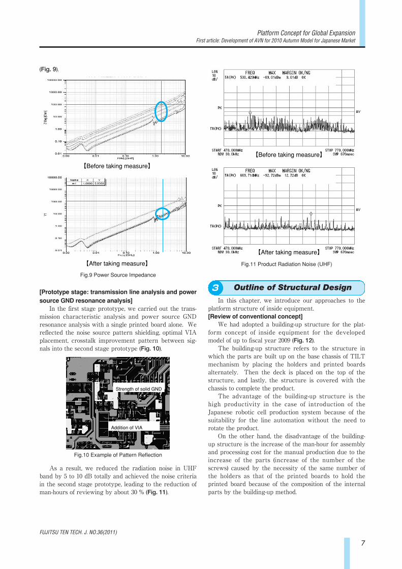
(Fig. 9).
[Prototype stage: transmission line analysis and powersource GND resonance analysis]In the first stage prototype, we carried out the trans-
mission characteristic analysis and power source GNDresonance analysis with a single printed board alone. Wereflected the noise source pattern shielding, optimal VIAplacement, crosstalk improvement pattern between sig-nals into the second stage prototype (Fig. 10).
As a result, we reduced the radiation noise in UHFband by 5 to 10 dB totally and achieved the noise criteriain the second stage prototype, leading to the reduction ofman-hours of reviewing by about 30 % (Fig. 11).
3. Outline of Structural Design
In this chapter, we introduce our approaches to theplatform structure of inside equipment.[Review of conventional concept]We had adopted a building-up structure for the plat-
form concept of inside equipment for the developedmodel of up to fiscal year 2009 (Fig. 12).The building-up structure refers to the structure in
which the parts are built up on the base chassis of TILTmechanism by placing the holders and printed boardsalternately. Then the deck is placed on the top of thestructure, and lastly, the structure is covered with thechassis to complete the product.The advantage of the building-up structure is the
high productivity in the case of introduction of theJapanese robotic cell production system because of thesuitability for the line automation without the need torotate the product.On the other hand, the disadvantage of the building-
up structure is the increase of the man-hour for assemblyand processing cost for the manual production due to theincrease of the parts (increase of the number of thescrews) caused by the necessity of the same number ofthe holders as that of the printed boards to hold theprinted board because of the composition of the internalparts by the building-up method.
【After taking measure】
【Before taking measure】
Fig.9 Power Source Impedance
【Before taking measure】
【After taking measure】
Fig.11 Product Radiation Noise (UHF)
Strength of solid GND
Addition of VIA
Fig.10 Example of Pattern Reflection
Outline of Structural Design3

8
FUJITSU TEN TECH. J. NO.36(2011)
FUJITSU TEN TECHNICAL JOURNAL
[New platform for global expansion]We regarded this 110M as a fundamental develop-
ment and considered the platform concept of insideequipment, seeking "easy manufacturing" and "low cost"conforming to the production method (in the subsidiariesoutside Japan). And then we set the following develop-ment targets to carry out the concept design:・Cost target: reduction by 30%・Parts target: reduction by 30%・Screws target: reduction by 30%・Weight target: reduction by 20%We introduce the main approaches below.
3.1 Design for Space-savingFirst, in the product planning department, the deriva-
tive models development plan over the next three yearsand their required functions were extracted, and in theelectric department, the required area of the printedboard was calculated based on the close investigation onthe functions in accordance with the needs of each coun-try. The basic structure of the printed board includes twoprinted boards composed of one audio printed board andone CPU printed board, and the CPU printed board isfixed on the face of one holder and the audio printedboard is fixed on the reverse side of the holder to save thespace (Fig. 13). As a result, as for the extended functions,we were able to get space for installation of the additionalprinted board. This allows us to respond to the additionalfunctions without any modifications of the basic structure.
3.2 Approaches to Reduction of Screws andFront PanelIn this platform, we optimized the structure using a
stress simulation at the conceptual stage to reduce thenumber of screws and weight while maintaining thesame strength as that of the building-up structure.As for the screws, we implemented optimum arrange-
ment of the screws as follows: under the assumption ofthe application of the impact load equivalent to 60 G inCAE analysis, we ran a tensile/shear stress simulation foreach screw (Fig. 14). Then we removed the unnecessarytightening and together tightened the areas that are ableto share the tightening wherever possible.
As for the chassis, under the assumption of the appli-cation of the impact load equivalent to 60 G, we selectedproper board thickness and optimized the shape based onthe stress distribution of the chassis surface. Also weconcurrently ran a vibration resistance simulationbecause of concern about the influence on the deck vibra-tion resistance due to the shape change (Fig. 15).As a result, we were able to remove the front panel
structurally.
Previous model
Building-up structure
Fig.12 Exploded Diagram of Current AVN Lite
Fig.14 Impact Simulation
Fig.15 Deck Vibration Resistance Simulation
CPU printed board
Audio printed board Space for extension printed board
Fig.13 Printed Wiring Board ASSY

9
FUJITSU TEN TECH. J. NO.36(2011)
Platform Concept for Global Expansion First article: Development of AVN for 2010 Autumn Model for Japanese Market
We concerned about the influence of ANT noise radi-ation to the vehicle due to the removal of the front panel.Therefore, we ran the product noise simulation as well asthe above-mentioned printed board noise simulation toincorporate the quality at the stage prior to prototypeproduction (Fig. 16).
Also we ran a temperature simulation. In this way,running of the simulation concurrently allowed us tocarry out the short-term development and quality front-loading.Through our main approaches described above, we
reduced the cost by minimizing the functions of compo-nent parts and reviewing the platform concept. Also wereduced the man-hour for development design of deriva-tive models by restricting the changes for the additionalfunctions. Fig. 17 shows the structure of inside equip-ment of AVN 110M.
Table 1 shows the results compared to the targets setat the beginning of development.
4. Software Configuration
For global expansion, we have to consider the expan-sion of the AVN to every region in the world. In otherwords, we need to respond to the diversification of speci-fications for each country and region. To respond to theenormous number of models, we needed to establish thestructure easily capable of replacing each function notonly in AVN Lite series but also in other models, and tominimize the man-hour. Fig. 18 shows the software con-figuration.In this chapter, we explain three changed points of
the software configuration to respond to a wide variety ofmodels and specifications (box with red border in Fig. 18).
4.1 Common I/FFirst, we established "common I/F (Inter Face)" oper-
ating resources of OS (Operating System) used by eachapplication. This reduces the dependence on the OS byeach application and easily transports the applicationoperating on other OS.Next, we established "model dependence layer" absorb-
ing the difference of the OS for I/F standardization.In this way, we aimed to establish the structure for
standardization of software including other models.
Fig.16 Product Noise Simulation
Fig.17 Inside Structure of AVN 110M
Windows Automotive5.5
Flash engine
Flash contents (HMI)
DirectShowFile System
GDI-subError Handling Ready Guard
DirectDraw
Navi Radio CD1Seg USBiPod
Mainly changed
Common I/F
Model dependent layer
Fig.18 Software Configuration and Main Changed Points
Number of parts Number of screws Weight of internal equipment
Reduced by 37.5% Reduced by 40.5%
Reduced by 21.3%
Result
15 39
2290g
110M
24 71
2912g
AVN LiteReduced by 30% Reduced by 30%
Reduced by 20%
Target
Table 1 Comparison between AVN Lite and AVN 110M
Software Configuration4

4.2 Adoption of Flash Engine4.2.1 Response to AnimationPreviously we had established HMI (Human Machine
Interface) by Fujitsu Ten's own drawing frame work(hereinafter, referred to as F/W). However, the drawingF/W had reached the limit due to the multi specificationsfor the global expansion. Hence we installed an engine(NetFront FlexUI produced by ACCESS) for playback ofFlash Lite contents to enrich the HMI such as the ani-mation.It was difficult to implement an animation in the pre-
vious model (AVN-Lite before 2009 model). However, theadoption of the Flash engine allowed us to easily imple-ment the animation and ensure the smooth animation.Fig. 19 shows the screen during switching between "mul-tiple screens including a map display screen for naviga-tion and a display screen for radio function" and "full-screen for radio function." In this way, imaging duringthe animation that we had not achieved previouslybecame possible. We use the animation effect for a pop-up warning screen and a counter of playback time.
4.2.2 Change of Development ProcessThe adoption of the Flash engine allowed us not only
to ensure the animation but also to review the develop-ment process.Fig. 20 shows the development process before/after
the review.Currently, the screen specification and screen transi-
tion specification are created in the planning departmentand they are provided to the software developmentdepartment. However, the specifications cannot includeall concepts of the planning department and the specifica-tions often have to be changed after the screen transitionand screen design are incorporated. The adoption of theFlash will allow anyone to create the screen specificationand screen transition specification on a PC using a tool,and therefore, the Flash file including the screen designand screen transition specification can be created at theplanning department. In other words, the creation of amoving specification becomes possible. In the softwaredevelopment department, it will be possible to implementthe functions of products by incorporating the motionduring pushing a button, based on the Flash data. Also itwill be possible to preliminary confirm the motion that
we cannot confirm until the motion is incorporated intothe product actually, and it is expected to reduce theman-hour of software development.
4.3 Adoption of Windows®For the global expansion, we needed to transfer the
platform of software from existing iTRON OS to univer-sal OS. The iTRON is the most popular OS in Japan butnot in other countries. For the global expansion, weneeded to replace the iTRON OS with more popular OS.Especially, it was essential to shift to the platform capableof replacement because of the installation of the naviga-tion application (hereinafter, referred to as navi-appli) inaccordance with the needs of each country/region.Hence, we adopted "Windows® Automotive5.5 (here-inafter, referred to as WA5.5)," for vehicle installation,based on Windows® CE which is the most popular OS forPDA (Personal Digital Assistant).Adopting the universal OS such as Windows® also
has the following advantages:・It has various middleware as standard.
(File System, decoder for MP3, communication func-tion, etc.)・There are many manufacturers to develop it.
These show that the universal OS such asWindows® has potential to install the functionsmeeting the customers' needs immediately.
4.3.1 Issues on Transition to WindowsWindows® CE 5.0 for general incorporation had been
thought to be not suitable for the vehicle installationbecause the Windows® CE 5.0 takes time to start up.However, this problem was resolved by adopting theWA5.5 in which the solutions for the high-speed start-uphas been provided. However, we still had issues on theimplementation so needed to take enough time to exam-ine the issues in the early phase of development. One ofthe solutions for the high-speed start-up of WA is ReadyGuard (hereinafter, referred to as RG). Here we explainthe system of the RG (Fig. 21).
10
FUJITSU TEN TECH. J. NO.36(2011)
FUJITSU TEN TECHNICAL JOURNAL
Slide IN/OUTSlide IN/OUT
Fig.19 Example of Animation
Design/transition specification
Screen design
Coding
Specification
Transition design
Coding
<Currently> <Future>
Flash data
Transition design
Coding
Screen design
CodingSoftware design
Creation of specifi-cation of screen and transition with Flash (moving specification)
Button parts data Indication position (coor-dinate) Screen transition spec-ification
Fig.20 Change of Development Process

When the WA is started, the OS with the minimumconfiguration, called RG OS, is started at high speed first-ly (Fig. 21-a). The minimum module that has to be start-ed up can be started up. As a result of the various exam-ination, we decided to start up the in-vehicle LAN com-munication function, communication function betweenmicrocomputers, power supply control function, etc.Next, MAIN OS is started up in parallel with the RG
OS. When the preparation for start-up of the MAIN OSis completed, the OS is switched from the RG OS to theMAIN OS (Fig. 21-b). In this case, the process operatingon the RG OS continues in the MAIN OS, and the RG OSstops. In this way, the functions that have to start up athigh speed are started up by the RG OS, and the processsuch as the navi-appli that may be started up later isstarted up by the MAIN OS to realize the high-speedstart-up.
5. Conclusion
As for the AVN by Ryohin-Renka (low-cost and non-defective product), we developed our own platform forthe global expansion by sorting out the performance andfunctions based on the regional characteristics and cus-tomers requirements.We hope to improve the convenience of our cus-
tomers by advancing and developing the products thathave linkage with the vehicle and various informationcenters, which only the single piece of in-vehicle equip-ment had not achieved.Lastly, we express our sincere appreciation to manu-
facturers of software and device for their supports in thedevelopment of this platform.
11
FUJITSU TEN TECH. J. NO.36(2011)
Platform Concept for Global Expansion First article: Development of AVN for 2010 Autumn Model for Japanese Market
Process 2 Process 3Process 1
Ready Guard OS MAIN OS
Threads Threads Threads
Process 2 Process 3Process 1
Ready Guard OS MAIN OS
Threads Threads Threads
Switching from RG OS to MAIN OS
SwitchingSwitching
〔a〕
〔b〕
Fig.21 Structure of High-speed Start-up
Conclusion5
Profiles of Writers
Takashi EGUCHIEntered the company in 2003. Sincethen, has engaged in the advanceddevelopment of AVN after the AVNsystem design. Currently inEngineering Planning Department,Advanced System Planning Division,Products Management Group.
Kazunari MIZOWAKIEntered the company in 2001. Since2006, has engaged in the softwaredevelopment of AV products afterworking in engineering developmentdepartment. Currently in SoftwareEngineering Department 1, CISoftware Division, SoftwareEngineering Group.
Toshihito SAWAIEntered the company in 1981. Sincethen, has engaged in the developmentof AVN after the development ofaudio equipment. Currently theDepartment Manager of EngineeringPlanning Department, AdvancedSystem Planning Division, ProductsManagement Group.
Junji ONISHIEntered the company in 2005. Sincethen, has engaged in the mechanicaldevelopment of AVN. Currently inMechanical Engineering Department,CI Engineering Group 1.
Fumitake NAKAMURAEntered the company in 2003. Sincethen, has engaged in the productplanning of navigation/audio system.Currently in Aftermarket PromotionDepartment, Product ManagementDivision 1, Products ManagementGroup.

12
Recently, the market needs has grown for the vehicle-mounted camera system to supplement driver's visualfield, mainly those for back monitors. Moreover, the technologies for the system are advancing. Among them,one technology provides images of downward view from the sky (bird's eye view images) to drivers by using fourfish-eye cameras, for easy parallel parking, etc. Products using this technology have been commercialized one afteranother.
The conventional system was useful only in limited scene because it could provide images of limited areas andfrom limited angles.
With "the 3-D virtual projection viewpoint conversion technology," we developed "Multi Angle Vision™,"which is a surrounding monitoring system that combines video images into 3-dimensional images with the areanear the vehicle displayed onto a plane representing the road, and the surrounding area distant from the vehicleonto curved surface.
This system is characterized by displaying images of the surroundings of the vehicle in 3-dimensional bird's eyeview from any arbitrary angle according to driving scene such as parking, and greatly contributes to supplementdriver's visual field. Moreover, the nighttime visibility is ensured for the right and left sides of the vehicle wherevisibility is poor when the illumination intensity is low, e.g. in the nighttime, by adopting a near infrared LEDlighting system, which allows drivers to see entirely around their vehicles even in the nighttime.
Abstract
Seiya SHIMIZU
Susumu TANIGUCHI
Tadashi KIDENA
Hiroshi YAMADA
Masahiro YAMADA
Multi Angle Vision™ System to supplementDriver's Visual Field

13
FUJITSU TEN TECH. J. NO.36(2011)
Multi Angle Vision™ System to supplement Driver's Visual Field
1. Introduction
Recently, an increasingly popular system is the vehi-cle-mounted camera system that assists drivers in check-ing the surroundings of their vehicles that the driverscannot see directly (to supplement drivers' visual field),by displaying camera images of the surroundings. Inrecent days, manufacturers have released new productsone after another. Those products are equipped with thesystem that supplements the driver's visual field (systemto supplement driver's visual field) by combination of twoor more cameras, rather than by one camera, to reducethe blind zones in broader range. The technology for thevehicle-mounted camera system is advancing.FUJITSU TEN has developed "Multi Angle Vision™,"
which is the world first system to supplement driver'svisual field that can display 3-dimensional bird's eye viewimages of the entire circumference of the vehicle fromvarious angles. This paper introduces the outline and ele-ment technologies of the Multi Angle Vision™.
2. Reasons for Development
2.1 Market Needs for Vehicle-mounted CameraSystemRecently, the needs for the vehicle-mounted camera
system, mainly back monitors, have been grown. Forexample, in February 2008, the U.S. congress passed thebill "Cameron Gulbransen Kids and Cars Safety Act of2007," which requires securing rearward visibility behindthe vehicle. In Japan, the vehicle- mounted camera sys-tem to supplement driver's visual field rapidly becomespopular with more than 4 million cameras to be mountedon vehicles shipped from factories in 1997. It is expectedthat a recent increase in women drivers and senior dri-vers will further enhance the needs for the vehicle-mounted camera system in the future.
Examples of Conventional Vehicle-mounted CameraSystems・Back monitorTo supplement driver's visual field when a driver
backs the vehicle by displaying camera images behindthe vehicle, using a camera on the rear end of the vehicle ・Blind corner monitorTo supplement driver's visual field when a driver
enters an intersection with poor visibility by displayingcamera images ahead of the vehicle, using a camera onthe front end of the vehicle ・Bird's eye view image systemTo supplement driver's visual field when a driver par-
allel parks the vehicle by displaying camera imageslooked down from the sky above the vehicle, using fourcameras on the vehicle
Moreover, many manufacturers have commercializedvarious types of products using the vehicle-mounted cam-era system, ranging from the system equipped with onecamera such as a backside camera (back monitor) to thebird's eye view image system equipped with four cam-
eras providing camera images looked down from the skyabove the vehicle to show the road situation near thevehicle. The technology for the vehicle-mounted camerasystem is advancing as the market needs for the systemis increasing.
2.2 Problems in Conventional System toSupplement Driver's Visual FieldDuring driving, drivers always have a feeling of
uneasiness that there may be something around the vehi-cle. All the vehicle-mounted camera systems described inthe previous section are intended to eliminate the uneasi-ness by providing camera images of zones that driverscannot see directly. Generally, the following three arecited as factors giving uneasiness to drivers.
①Vehicle body structure interrupting driver's visualfieldVehicle body, pillars, etc. ②Obstacles around vehicle interrupting driver's visual
fieldBuildings, other vehicles, pedestrians, etc.③Characteristics of human eyesUnable to see entire 360-degree surroundings at onetime
Actually, one or a combination of these factors existsand interferes with safe driving of drivers. Therefore,vehicle-mounted camera system is required to eliminateall these factors. However, the conventional system can-not sufficiently serve this purpose. For example, a backmonitor or a blind corner monitor supplements the dri-ver's visual field by displaying camera images of blindzones created by the vehicle body or an obstacle(s)around the vehicle, in the scenes where the driver isassumed to use the monitor system. However, those sys-tems only provide partial images of the blind zones suchas the area behind the vehicle or the area behind a wall.In terms of supplementing the characteristics of humaneyes, those systems do not fulfill the purpose. Moreover,the bird's eye view image system can show road condi-tions around the vehicle at one time by providing cameraimages looked down from a higher position over the vehi-cle. However, the camera images are limited to the viewfrom a predetermined fixed angle so that the images areonly useful under limited scenes. As a result, convention-al systems supplement the driver's visual field by display-ing no more than partial images of blind zones around thevehicle only under limited scenes where each of thosesystems is supposed to support the driver, and do notachieve the comprehensive support including supple-menting of the characteristics of human eyes. In addition to elimination of those factors, it is impor-
tant to take measures to improve cameras for betternighttime visibility. Compared to the bright daytime, it ismore difficult to notice the existence of obstacles on thedisplay in the nighttime when it is dark after the sunsinks because camera images captured by cameras arealso dark (Fig. 1). It is required to improve the camerasso that they surely capture the images of obstacles
Introduction1
Reasons for Development2

14
FUJITSU TEN TECH. J. NO.36(2011)
FUJITSU TEN TECHNICAL JOURNAL
around the vehicle even under the dark environment.
This time we developed "Multi Angle Vision™," whichsupplements not only the driver's visual field to eliminateblind zones created by the vehicle body and/or obstaclesaround the vehicle but also the characteristics of the dri-vers' eyes. The Multi Angle Vision™ allows drivers tosee entire 360-degree surroundings of the vehicle fromvarious angles. Therefore, it is the system to supplementdriver's visual field that is capable of supporting the visu-al field of users in total from when they get in their vehi-cles to when they drive the cars.
3. Element Technologies of "Multi Angle Vision™," System to supplement Driver's Visual Field
3.1 Outline of Multi Angle Vision™The Multi Angle Vision™ is the world's first system
that supplements the driver's visual field. Using an ECU,the system combines images around a vehicle capturedby four cameras that are used only for this system andthat mounted on the right side, left side, front end andrear end of the vehicle, and displays 3-dimensional bird'seye view images, to allow the drivers to see around thevehicle including blind zones. This system includes four cameras dedicated for this
system, an ECU, and an AVN. The images around thevehicle, captured by the four dedicated cameras, areaggregated in the ECU. The aggregated images are com-bined into an image on a real-time basis and projected ona 3-dimensional model using the "3-D virtualprojection/point of view conversion technology 1)." Theimages are displayed on the AVN in accordance with thescene to supplement the driver's visual field (Fig. 2).
The "3-D virtual projection/point of view conversiontechnology" allows this system to display bird's eye viewimages 360-degree around the vehicle from any arbitraryposition in 3-dimension. For example, using this system,an image can be rotated around the vehicle of the driverto check the safety around the vehicle, as shown in Fig. 3.Moreover, unique images that cannot be achieved by theconventional system can be displayed. An example ofthose images is the one showing the vehicle viewed frombehind the vehicle, as shown in Fig. 4. The images beloware a couple of other image examples able to be displayedby the system (Fig. 5 and Fig. 6).
Cameras dedicated for Multi Angle Vision™Horizontal angle of view: 190 degrees Side cameras: built-in near-infrared LED
ECU Combine images using "3-D virtual projection/point of view conversion technology"
AVN (compatible with Multi Angle Vision™)
Display of image in accordance with scene
Front camera
Back camera
Side camera (Passenger's side)
Side camera (Driver's side)
Fig.2 Outline of Multi Angle Vision™
Daytime
Nighttime
Fig.1 Difference in Camera Image Brightness between
in Daytime and in Nighttime
Element Technologies of "Multi Angle Vision™,"System to supplement Driver's Visual Field3

15
FUJITSU TEN TECH. J. NO.36(2011)
Multi Angle Vision™ System to supplement Driver's Visual Field
On the other hand, the cameras of this system mustbe mounted with extreme accuracy. In order to makesure of the mounting of the cameras at the accurate posi-tions, "calibration" is performed to correct tiny errorsmade during the mounting of the cameras so that mis-alignment of combined images does not occur. Moreover, we developed "near infrared LED lighting
system" in order to enhance the visibility of cameraimages of obstacles around the vehicle in the nighttime.This improvement enhances the visibility of cameraimages captured in the nighttime and enables the systemto supplement the driver's visual field in the daytime andnighttime. Furthermore, the system equipped with functions to
meet the future expansion of models of vehicles, such asa slot for a SD card on the ECU to read in data forupgrading.The outline and the structure of the Multi Angle
Vision™ are mentioned above. The following sectionswill explain the key element technologies for the MultiAngle Vision™: 3-D virtual projection/point of view con-version technology; calibration; and the technology forenhancing nighttime visibility using near infrared LEDlighting system.
3.2 Technology for Showing Surroundings Allaround Vehicle from Arbitrary ViewpointThe camera images from four cameras mounted on
the vehicle are combined using the "3-D virtual projec-tion/ point of view conversion technology." The "3-D vir-tual projection/point of view conversion technology" isthe technology that projects an image on a 3-D model andthen converts the projected image into the image viewedfrom an arbitrary viewpoint. Using this technology, ournewly developed system is able to show images substan-tially different from the one created by conventional sys-tems using conventional technologies. The conventional bird's eye view image system con-
verts camera images from the four cameras, on a 2-Dplain surface to combine them into bird's eye viewimages. Therefore, objects around the vehicle arestretched in those images. Another disadvantage of theconventional system is that it is only capable to displaydownward images viewed from a certain viewpoint overthe vehicle. That means that the system is only useful toshow certain areas and for certain scenes (Fig. 7).
Fig.3 Image Used for Check Surroundings of Vehicle
Fig.4 Image Used for Check at Intersection with Poor Visibility
Fig.5 Image Used for Parking
Fig.6 Image Used for Parking on Verge of Road
Fig.7 Image Example Projected on 2-D Model

16
FUJITSU TEN TECH. J. NO.36(2011)
FUJITSU TEN TECHNICAL JOURNAL
On the other hand, our new system combines cameraimages on the 3-D model where the area near the vehicleis designed to be projected on the plain surface of a roadand the area distant from the vehicle on a curved surface(Fig. 8), which can prevent objects around the vehiclefrom being stretched out of shape and can provide dri-vers with camera images of an area wider than the oneprovided by conventional systems. In addition, by includ-ing a LSI capable of fast arithmetic processing, this sys-tem can computes an image from a viewpoint, in realtime. Therefore, besides the conventional bird's eye viewimages viewed from the sky over the vehicle, imagesaround the vehicle viewed from various angles can beprovided to drivers, and the driver's visual field can besupplemented in many scenes.
3.3 Seamlessly Combined Camera ImagesThe calibration is performed to correct misalignment
of combined images caused by a tiny error in position ofthe cameras when the system is mounted. Calibration isa technology that automatically computes the mountinginformation (position and angle) of each of the camerasmounted on a vehicle by capturing the camera images ofmarkers around the vehicle by those cameras, and thencombines the camera images seamlessly while automati-cally adjusting tiny misalignment caused on the combinedimages in accordance with the computation results.This technology enables the system to combine the
camera images seamlessly and to eliminate borderlinesbetween camera images captured by the camerasalthough those borderlines are conspicuous between thecamera images combined by conventional systems (Fig. 9).
The calibration adopts the method that eases restric-tions relating to work space, work time and equipment.For example, the markers are allowed to be placed atarbitrary positions if the cameras can capture the mark-ers. Therefore, it does not have to secure work spaceused only for the Multi Angle Vision™. The applicationused for the work is installed in the ECU. The work canbe performed using the AVN so that there is no need toprepare special equipment (such as a PC).
3.4 Supplementing of Drivers' View in NighttimeIn the nighttime, the camera images captured by the
cameras are dark and visibility becomes lower. In thecase of a vehicle-mounted camera system with camerasrespectively mounted on the front end, back end, rightside and left side of a vehicle, the cameras on the frontand back ends can capture relatively bright images dueto the lighting system originally installed on the vehicle.However, the images captured by the side cameras aredark because there is no lighting system to light the sidesof the vehicle (Fig. 10).
Combining the camera images on which the sides ofthe vehicle are dark only produces combined bird's eyeview images with the dark sides of the vehicle.Therefore, a lighting system is required to develop toensure the visibility of the side cameras. The followingare the three points that we addressed to develop a light-ing system for the side cameras.
Conventional Multi Angle Vision™
Fig.9 Examples of Borderlines between Camera Images
Front Back
Left Right
Fig.10 Camera Images Captured in Nighttime
Possible to check area around vehicle from various angles
Fig.8 Image Example Projected on 3-D Model
17
FUJITSU TEN TECH. J. NO.36(2011)
Multi Angle Vision™ System to supplement Driver's Visual Field
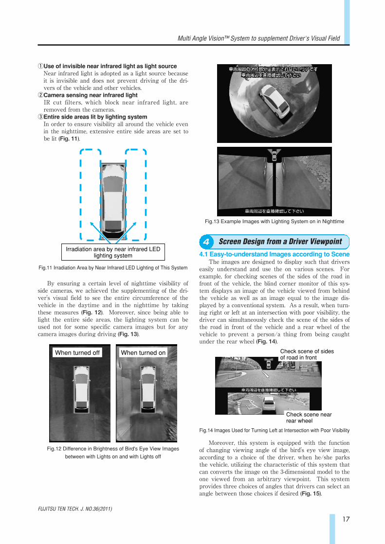
①Use of invisible near infrared light as light sourceNear infrared light is adopted as a light source becauseit is invisible and does not prevent driving of the dri-vers of the vehicle and other vehicles.
②Camera sensing near infrared lightIR cut filters, which block near infrared light, areremoved from the cameras.
③Entire side areas lit by lighting systemIn order to ensure visibility all around the vehicle evenin the nighttime, extensive entire side areas are set tobe lit (Fig. 11).
By ensuring a certain level of nighttime visibility ofside cameras, we achieved the supplementing of the dri-ver's visual field to see the entire circumference of thevehicle in the daytime and in the nighttime by takingthese measures (Fig. 12). Moreover, since being able tolight the entire side areas, the lighting system can beused not for some specific camera images but for anycamera images during driving (Fig. 13).
4. Screen Design from a Driver Viewpoint
4.1 Easy-to-understand Images according to SceneThe images are designed to display such that drivers
easily understand and use the on various scenes. Forexample, for checking scenes of the sides of the road infront of the vehicle, the blind corner monitor of this sys-tem displays an image of the vehicle viewed from behindthe vehicle as well as an image equal to the image dis-played by a conventional system. As a result, when turn-ing right or left at an intersection with poor visibility, thedriver can simultaneously check the scene of the sides ofthe road in front of the vehicle and a rear wheel of thevehicle to prevent a person/a thing from being caughtunder the rear wheel (Fig. 14).
Moreover, this system is equipped with the functionof changing viewing angle of the bird's eye view image,according to a choice of the driver, when he/she parksthe vehicle, utilizing the characteristic of this system thatcan converts the image on the 3-dimensional model to theone viewed from an arbitrary viewpoint. This systemprovides three choices of angles that drivers can select anangle between those choices if desired (Fig. 15).
Irradiation area by near infrared LED lighting system
Fig.11 Irradiation Area by Near Infrared LED Lighting of This System
Check scene near rear wheel
Check scene of sides of road in front
Fig.14 Images Used for Turning Left at Intersection with Poor Visibility
When turned off When turned on
Fig.12 Difference in Brightness of Bird's Eye View Images
between with Lights on and with Lights off
Fig.13 Example Images with Lighting System on in Nighttime
Screen Design from a Driver Viewpoint4

18
FUJITSU TEN TECH. J. NO.36(2011)
FUJITSU TEN TECHNICAL JOURNAL
4.2 Matching of Vehicle CG to Mounting VehicleFurthermore, this system is equipped with the func-
tion with which the driver can change the model and thecolor of the vehicle CG located in the center of the bird'seye view image to match with the real vehicle mountingthe system. As a result, although vehicles vary in sizeand shape, this system is capable of displaying the scenearound the vehicle faithfully in accordance with the sizeand the shape of the vehicle (Fig. 16). Furthermore, withthis function, the color of the vehicle CG on the image alsocan be changed to provide a sense of reality to the driver.
5. Conclusion
We have developed "Multi Angle Vision™," whichcomprehensively supplements the field of view of driversin the daytime and in the nighttime, using the "3-D virtualprojection/point of view conversion technology" and the"technology for enhancing nighttime visibility using nearinfrared LED lighting system." The Multi Angle Vision™has been commercialized as an option to be installed atcar dealers (dealer option) for ALPHARD, VELLFIREand PRIUS of TOYOTA MOTOR CORPORATION sinceMay 2010.We think that this system can provide safety to dri-
vers in various driving scenes and can contribute greatlyto the safety in the car society. We would like to makean effort to enhance safety precautions and assistance inparking in addition to the supplement of the field of viewof drivers, in the future.
Reference: 1) SHIMIZU Seiya, et al, "System Giving WraparoundView of Vehicles", FUJITSU, Vol.60, No.5, pp.496-501(2009)
視点角度 0°
視点角度 30°
Screen for angle selection
Fig.15 Images at Different Viewing Angles
ALPHARD
PRIUS
Fig.16 Example of Vehicle CGs according to Vehicle Model
Conclusion5
Profiles of Writers
Profiles of External Writers
Seiya SHIMIZUEntered FUJITSU LABORATO-RIES LTD. in 1989. Since then, hasengaged in R&D of computer graph-ics and image processing systems.Currently works at ITS ResearchCenter.
Susumu TANIGUCHIEntered the company in 2008. Sincethen, has engaged in the developmentof vehicle-mounted camera systems.Currently in Engineering Dept. 4,System Division, ITS EngineeringGroup.
Tadashi KIDENAEntered the company in 1986. Sincethen, has engaged in the developmentof car multimedia products (CD/TVcombination products, AVN, etc).Currently in Engineering Dept. 4,System Division, ITS EngineeringGroup.
Masahiro YAMADAEntered the company in 1990. Sincethen, has engaged in the developmentof sound control technology andimage recognition systems. Currentlyin Engineering Dept. 4, SystemDivision, ITS Engineering Group.
Hiroshi YAMADAEntered FUJITSU LABORATORIESLTD. in 1988. Since then, hasengaged in R&D of advanced terminalsystems such as mobile terminals, in-vehicle visual systems. Since April2009, has worked at FUJITSU TENLIMITED. Also works for FUJITSULABORATORIES LTD.

19
Fujitsu Ten has been developing automotive radar using the millimeter-wave (30GHz to 300GHz) since beforewe were separated from Fujitsu, and we started its mass production in 2003. In this article, we introduce our his-tory of our own radar development for more than 30 years. In addition, we explain a waveguide slot antenna forautomotive application and a low-profile triplate antenna whose mass production was started in 2003, focusing onthe background of the antenna development.
For further reduction of the cost of the automotive radar, we developed microstrip antennas effective in lower-ing cost with its extremely simple structure and then reduced the cost by 80%. We also explain our efforts of thedesign for reduction of transmission loss and the development of printed board materials.
Abstract
Yoshihide UEZATO
Hiroaki YOSHITAKE
Masayoshi SHONO
Masahiko FUJIMOTO
Toshiki YAMAWAKI
Compact and High-performance Millimeter-wave Antennas

20
FUJITSU TEN TECH. J. NO.36(2011)
FUJITSU TEN TECHNICAL JOURNAL
1. Introduction
In the 1980's, Fujitsu Ten made a prototype of V-typeradar for evaluation on vehicle installation and securedthe prospect of practical application of automotive radar,using the waveguide slot antenna. In the 1990's, wedeveloped the radar with mechanical scan system adopt-ing triplate antenna to improve the installability anddetection capability on curves, and then commercialized itin 2003. Now, we promote an establishment of designtechnology of comb-line microstrip antenna and develop-ment of its commercialization for the price reduction ofantenna.In the antenna development, there had been changes
in the antenna shape, from solid antenna to planar anten-na as well as in the materials, from waveguide usingmetal to dielectric body. In this article, we introduce thehistory of our antenna development and our currentapproach.
2. History of Automotive Radar Development
2.1 Start of DevelopmentIn the 1970's, the necessity of the automotive radar
began to be recognized as measures to reduce increasingautomotive accidents. The frequency allocation policy of40 GHz or more was decided by Ministry of Posts andTelecommunications at the time and technically 50GHzconvenience radio had been put to practical use. In thisway, the development environment for the automotiveradar began to be improved from standpoints of socialneeds, government trend toward the radio wave andtechnical aspects.In 1974, Fujitsu Limited (hereinafter, referred to as
Fujitsu) newly established the Motronics developmentdepartment to develop the automotive radar. In thisdepartment, the possibility of the automotive radar in themillimeter waveband was examined firstly. Giving priori-ty to the detection capability, a prototype model forexamination was made, using high-gain and large-sizeCassegrain antenna with a diameter of about 30 cm. Theevaluation on the detection capability with this prototypemodel showed that the millimeter waveband was effec-tive as the automotive radar.In 1979, the development of the automotive radar in
Fujitsu was transferred to Fujitsu Ten without anychange of the development organization.In the 1980's, Fujitsu Ten commissioned the develop-
ment of high-frequency device to Fujitsu. We developedthe high-gain and small-size waveguide slot antenna andmade a prototype of V-type radar to be installed in thevehicle. With the cooperation of Toyota MotorCorporation, we installed the V-type radar in Toyota'sspecialty car Soarer and carried out a test run on theopen road and a test in cold climates. The fixed beamsystem was used in this radar, and therefore, we had aproblem of deterioration of the detection capability on the
curves. However, those tests showed that the V-typeradar fulfilled the performance required for the automo-tive radar, such as detection capability for a leading vehi-cle and separation from adjacent vehicles.
2.2 Approach to CommercializationIn the 1990's, there had been changes in the vehicle
design, from box-shaped design to slant nose design, andthus the automotive manufactures strongly demandedsmaller-size and thinner radar. We began to consider theintroduction of planar antenna effective in those demands.For its introduction, we had a problem of keeping thesame gain as that of the high-efficiency waveguide slotantenna. Therefore, we began to develop the millimeter-wave planar antenna for automotive use with HitachiChemical Company, Ltd. (hereinafter, referred to asHitachi Chemical) that produced the high-efficiency andplanar triplate antenna for DBS antenna at the time.Also in the 1990's, we set up a working group with
Ministry of Posts and Telecommunications (name at thetime) so that the radar manufacturers and automotivemanufacturers achieve the frequency allocation. As aresult, in 1997, the frequency of 60 GHz was allocated tothe automotive millimeter-wave radar. The frequencyallocation removed the significant barrier of laws and reg-ulations for the commercialization and activated the com-mercialization by each manufacture rapidly.Fujitsu Ten introduced the triplate antenna and
developed the radar with high-resolution mechanical scansystem, without the deterioration of detection capabilityeven on the curves by scanning the antenna mechanicallywith the advantages of thinness and lightness of theantenna. In 2003, we commercialized the radar, and in2006, we commercialized backward-looking radar.
2.3 Approach to Price ReductionThere is a problem of the price reduction of radar
with the spread of automotive radar. The microstripantenna using a printed board to be patterned by etchingis effective in the price reduction. However, it had notbeen used because of significant transmission loss in themillimeter-wave band and low efficiency.Recently, the microstrip antenna with low loss and
high efficiency by coupling the radiation element withfeed line has been offered (3) (4). Fujitsu Ten applies thistechnology and develops the materials with Nippon PillarPacking Co., Ltd. In this way, we have been approachingto the development of practical application of themicrostrip antenna.
3. History of Antenna Development
Fig. 1 shows the history of our antenna development.We began with the development of waveguide slot anten-na, and then we have been promoting the developmentfrom the triplate antenna to the microstrip antenna, aim-ing for the reduction in size/weight/price.
Introduction1
History of Automotive Radar Development2
History of Antenna Development3

21
FUJITSU TEN TECH. J. NO.36(2011)
Compact and High-performance Millimeter-wave Antennas
In this chapter, we describe details of structure andcharacteristic of each antenna that we developed.
3.1 Waveguide Slot AntennaFor the prototype model for the evaluation on vehicle
installation, we discussed the optimum beam width takinginto consideration the separation from adjacent vehiclesand influence of road surface reflection.As an antenna system to realize the optimum beam
width, we evaluated the prototype of the antenna usingthe several types of antennas such as cheese antenna,and compound antenna including the waveguide slotantenna and cylindrical parabola antenna. The antennasystem that synthesizes the beam by combining thetransmitting antenna and receiving antenna in a V shapemade it possible to form the small and sharp beam.The V-shape radar using this antenna system became
the model for evaluation on vehicle installation with excel-lent detection capability and installability by simplifyingand directly connecting between devices at high-frequen-cy area. We had carried out the test run on the open
road for about 10 years since 1982, and established thespecification as the subsequent radar and the antenna forradar.
3.1.1 Structure of Waveguide Slot AntennaAs shown in Fig. 2 (a), the transmitting antenna or
receiving antenna forms 2 degrees beam width with theprimary radiator of the waveguide slot antenna and 6degrees beam width with the cylindrical parabola reflec-tor. As shown in Fig. 2 (b), the transmitting/receivingbeam of 2 degrees×6 degrees beam width are combinedorthogonally to obtain the transmitting/receiving synthet-ic beam of 2 degrees×2 degrees.We ensure 45-degree polarized wave to avoid the
radio wave interference of oncoming vehicles. We usethe longitudinal shunt slot and edge shunt slot, whosepolarizations intersect at a right angle, as the transmit-ting/receiving antenna, and we keep the polarization inthe 45-degree direction by V-shape and orthogonalarrangement of the transmitting/receiving antenna.
1970's 1980's 1990's 2000'sConfirmation of effectiveness of millimeter wave
Smaller size/higher gain
Smaller size/ lighter/lower price
Smaller size/high performance/ further lower price
50GHz (experiment division)
Regulations 60GHz ▼Allocated in Japan
▼Allocated in Japan, U.S. and Europe 77GHz
Triplate antennaWaveguide slot array antenna
Cassegrain antenna
In 1974 First prototype
In 1982 Development of V-shaped radar
In 1998 60GHz Development of mechanical scan system radar
Microstrip antenna
Fixed beam system Mechanical scan systemMonopulse system Electronic scan system
In 2006 77GHz Commercialization of close-range radar
60GHz
In 2003 77GHz Commercialization of mechanical scan system radar
Close-range radar77GHz
Antenna development
Fig.1 History of Antenna Development

22
FUJITSU TEN TECH. J. NO.36(2011)
FUJITSU TEN TECHNICAL JOURNAL
3.2 Triplate AntennaFor commercialization of high-efficient millimeter-
wave planar antenna, Fujitsu Ten and Hitachi Chemicalimplemented joint development. The examination ofspecification as the automotive radar antenna and itsevaluation were implemented by Fujitsu Ten, and thedesign/prototype of antenna were implemented byHitachi Chemical.
3.2.1 Structure of Triplate AntennaAs shown in Fig. 3 (a), the triplate antenna is com-
posed of copper foil pattern (feed line and patch) formedby etching process on the extremely thin film substrate,parallel plate (slot plate and ground plane) placed at thetop and the bottom of the structure, and foam materialholding the film substrate. The transmission line fromthe feed line to patch is composed of the triplate trans-mission line held between the parallel plates shown inFig. 3 (b).The triplate transmission line has low dielectric loss
depending on the material and no radiation loss into thespace due to the interruption of signal by the parallelplates because the dielectric material such as resin sub-strate is not used in the space between slot plate andground plane, comprising the feed line. Therefore, thereis only conductor loss by the current in the parallelplates, and if the triplate transmission line is used in thefeed line of antenna, the planar antenna with high radia-tion efficiency is realized.
4. Development of Low-cost Antenna
To ensure the installability and scanning function atthe same time, the planar antenna is essential. Also, thedemand for the low cost has been increased with theexpansion of usage of automotive radar and its spread.Among the planar antennas, the microstrip antenna hav-ing simple structure is effective in the price reduction.However, there is a problem of high transmission loss anddecrease in efficiency because the resin substrate is usedfor the microstrip antenna.As a solution for this problem, there is technique to
directly connect the radiation element and feed line (3).This technique reduces the transmission line loss to eachradiation element, and therefore, the microstrip antennawith high efficiency is realized. With the cooperation ofToyota Central R&D Labs., INC., we worked on the com-mercialization development including the optimum designof this type of antenna.
Slot array
Parabola reflector
Polarization
Receiving antenna
Transmitting antenna
Parabola reflector
Edge slot array
Receiving antenna pattern
Transmitting antenna pattern
Synthetic beamAdoption of synthetic beam system
Edge shunt slot array
Longitudinal shunt slot array
E
6°
2°
E
(a) Transmitting or receiving antenna pattern
(c) Waveguide slot
(b) V-shape arrangement of transmitting/receiving antenna(1)
Longitudinal shunt slot array
Reduction of radio wave interference by 45-degree polarized wave
2°
2°
Fig.2 Structure of Waveguide Slot Antenna(1)
Development of Low-cost Antenna4

23
FUJITSU TEN TECH. J. NO.36(2011)
Compact and High-performance Millimeter-wave Antennas
4.1 Structure of Microstrip AntennaFig. 4 (a) shows the structure of the feed line and radi-
ation element in the microstrip antenna, and Fig. 4 (b)shows the structure of the microstrip substrate.As mentioned above, the central transmission line
feeding the signal to each radiation element is directlyconnected with the radiation element. Furthermore, 45-degree polarized wave is also realized at the same timeby tilting the radiation element at a 45-degree angle.
4.2 Approach to CommercializationOur main approaches to the commercialization of the
microstrip antenna are as follows:①Selection of substrate material②Improvement design of antenna pattern characteristics③Robust designAmong the above-mentioned approaches, we describe
the examinations of ① selection of substrate materialand ② improvement design of antenna pattern charac-teristics.
4.2.1 Selection of Substrate MaterialAs for the substrate material, we examined every
characteristic such as electric property, mechanicalstrength, environment resistance and others. Especially,the electric property is a key issue because of the usageof substrate in the millimeter waveband.The electric property of substrate mainly has dielec-
tric constant and dielectric loss. The higher dielectricconstant, the narrower frequency width. Therefore,three or less of dielectric constant is suitable for antennamaterial. We focused on LCP (liquid crystal polymer)substrate and PTFE (poly-tetra-fluoro-ethylene) substrateamong the substrates with three or less of dielectric con-stant, and evaluated them.The dielectric loss affects the loss in the feed line,
and if the loss becomes high, the radiation efficiency isdeclined. Therefore, the dielectric loss is a critical indi-cator.As for the loss of the feed line, the prototype of evalu-
ation sample for only the feed line was made and the lossbetween both ends of line was measured. As a result, theLCP has a high feed line loss and inferior antenna efficien-cy than triplate antennal.On the other hand, PTFE has low loss and high possi-
bility to realize the high-efficiency antenna if the PTFE isused as the substrate material of the microstrip antenna.
Ground plane (aluminum)
Slot panel (aluminum)
Slot
Feed line
Patch
Film substrate
Feed line
Dielectric sheet (foam material)
Dielectric sheet (foam material)
(a) Antenna structure(2)
(b) Triplate transmission line
Fig.3 Structure of Triplate Antenna
Copper foil (ground plane)
Feed line
Dielectric body (resin substrate)
Feed line
Radiation element
45°
(a) Structure of feed line and radiation element
(b) Structure of microstrip substrate
Fig.4 45-degree Polarized Comb-line Microstrip Antenna

24
FUJITSU TEN TECH. J. NO.36(2011)
FUJITSU TEN TECHNICAL JOURNAL
4.2.2 Improvement Design of Antenna Pattern CharacteristicsIf the radiation element is arrayed linearly (Fig. 4 (a)),
the temperature characteristic of dielectric constantaffects the antenna pattern characteristic. If the dielec-tric constant is varied by the temperature, the wave-length inside of dielectric body is varied and the signalphase radiated from each radiator is varied. If the signalphase radiated from each radiation element is in phase,each signal phase becomes equal at the antenna frontside (in a vertical direction of antenna surface) and themain lobe peak becomes the antenna front side. If eachsignal phase is varied, the main lobe peak position ofantenna is varied (the beam tilts). Hence, as measuresagainst the influence exerted by the temperature charac-teristic of dielectric constant, on the antenna patterncharacteristic, we adopted a center-fed system to bedescribed in (a) below, and approached to the develop-ment for mass production with improvement design ofantenna pattern characteristic. This system had a newproblem of deterioration of side lobe ratio because thefeeding part was placed in the center of antenna.However, this problem was solved by the measuresdescribed in (b) below.
(a) Adoption of center-feeding systemIn the center-fed system, the phase variation symbol
of radiation element, divided into a right and a left halfwith reference to the feeding part, is reversed as shownin Fig. 5 (a), and therefore, the phase variation is negatedat the antenna front side and the peak position is not var-ied. However, by the presence of feeding part in the cen-ter of the antenna, the radiation from around center partis prevented and side lobe ratio of antenna pattern char-acteristic is deteriorated.The most significant task in adoption of center-fed
system is to reduce the deterioration of the side loberatio. Our approaches to this reduction are shown below.
(b) Reduction of side lobe ratio deteriorationAs shown in Fig. 5 (b), the feeding part is comprised
of the waveguide part and transducer part. The trans-ducer has function to reduce the reflection and loss in thecase of signal transmission between the waveguide forconnecting with RF part and feed line of antenna(microstrip line). For the center-fed system, the signal tobe input to the feeding part is needed to be divided intotwo and fed into the right-and-left radiation elements. Weachieved the same size of feeding part as that of the con-ventional one by adding the two-distribution function tothis transducer. Therefore, we were able to minimize thearea where the radiation cannot be given, and reduce theside lobe ratio deterioration. Fig. 6 shows the evaluationresult of antenna pattern. We obtained the gain, the sidelobe ratio, for the automotive radar antenna.
5. Conclusion
With the evolution of our millimeter-wave radar, wehave advanced the development of antenna from thewaveguide slot antenna to the triplate antenna andmicrostrip antenna. With the transition of antenna to bedeveloped, the materials and structures also had beenaltered significantly, and we had faced the task of efficien-cy, temperature characteristic, environment resistanceand others in the new structure. However, we had modi-fied and improved in each case and found out the possibil-ity of commercialization. We will establish the mass pro-duction design technology for millimeter-wave microstripantenna aimed at smaller size/lower price antenna byintroducing the robust design against machining errors.
Feeding part
Waveguide
Transducer (feeding element)
(a) Antenna structure
(b) Structure of feeding part
Fig.5 Structure of Center-fed Microstrip Antenna and its Feeding Point
-30
-20
-10
0
10
20
30
-90 -70 -50 -30 -10 10 30 50 70 90
Angle [deg]
Absolute gain [dBi]
Actual measured value
Horizontal pattern
Vertical pattern
Vertical side lobe ratio 14.5 dB
Fig.6 Evaluation Result of Antenna Pattern
Conclusion5

Reference1) Nogami, Uezato, Sakamoto, Isogai:Application of mm Wave Radar for VehiclesVol 3 No.22) Yamawaki, Yamano:60GHz Millimeter-Wave Automotive RadarVol 15 No.23) Iizuka, Watanabe, Sato, Nishikawa:Millimeter-wave Microstrip Line to WaveguideTransition Fabricated on a Single Layer DielectricSubstrate IEICE TRANS. COMMUN.Vol E-85B No.6 June 20024) Iizuka, Watanabe, Sato, Nishikawa:Millimeter-wave Microstrip Array Antenna forAutomotive Radar IEICE TRANS. COMMUN.Vol E-86B No.9 September 2003
25
FUJITSU TEN TECH. J. NO.36(2011)
Compact and High-performance Millimeter-wave Antennas
Profiles of Writers
Yoshihide UEZATOEntered the company in 1972. Sincethen, had engaged in the design ofmillimeter-wave radar system. Afterhis career in Engineering Department2, System Division, ITS EngineeringGroup, retired in September 2010.
Masahiko FUJIMOTOEntered the company in 1982. Sincethen, has engaged in the develop-ment/design of automotive electricalproducts and millimeter-wave radarsystem. Currently in EngineeringDepartment 2, System Division, ITSEngineering Group.
Toshiki YAMAWAKIEntered the company in 1984. Sincethen, has engaged in the production engi-neering of car audio products and in thedevelopment/design of hybrid IC for caraudio products as well as millimeter-waveradar system. Currently the GeneralManager of Engineering Department 2,System Division, ITS Engineering Group.
Hiroaki YOSHITAKEEntered the company in 2008. Sincethen, has engaged in the design ofmillimeter-wave radar antenna.Currently in EngineeringDepartment 2, System Division, ITSEngineering Group.
Masayoshi SHONOEntered the company in 1988. Sincethen, had engaged in the develop-ment of automotive electrical prod-ucts. Since 1991, has engaged in thedevelopment/design of millimeter-wave radar system. Currently inEngineering Department 2, SystemDivision, ITS Engineering Group.

26
FUJITSU TEN Limited has developed "TOYOTA Premium Sound System" using "spatial control technolo-gy" for CROWN of TOYOTA Motor Corporation in February 2008, which receives high reputation. We, atFUJITSU TEN Limited, and UNIVERSITY OF HYOGO have been collaborating on research activities of soundfield creation technology by a simultaneous equation method through the upgrade of the spatial control technolo-gy in order to provide sounds with more natural sense of expanse. Through verifying the principle with a simula-tion model, we confirmed that it provides appropriate controls depending on listener's moves and creates arbitrarysound field at the periphery of listener's ears. This new technology can provide precise controls depending on lis-tener's moves, and this leads to expansion of the spatial control range whose upper limit used to be 1.5 kHz. Wefound a clue to providing sounds with more natural sense of expanse.
Abstract
Kensaku FUJII
Isao WAKABAYASHI
Tadashi UJINO
Shigeki KATOH
Study of In-vehicle Sound Field Creation bySimultaneous Equation Method

27
FUJITSU TEN TECH. J. NO.36(2011)
Study of In-vehicle Sound Field Creation by Simultaneous Equation Method
1. Introduction
A vehicle cabin is one of the precious private spacesfor many drivers. Drivers can enjoy music as high quali-ty as at home with many digitized sources. Now, thevehicle cabin is an important space like a living room athome for a driver to enjoy music. However, looking at the vehicle cabin as a space for
enjoying music, it stands under many disadvantageousconditions for replaying music compared to a general liv-ing room; for example, with driving noises, limitations ofspaces for loudspeaker to be set, sound reflections fromvehicle windows and effects occurred by unnecessaryvibrations of interior materials. Thus, noise-sensitiveautomatic volume control 1), compact woofer 2), wide-direc-tional tweeter, equalizer for transmission characteristicscorrection in a vehicle cabin 3), sound field controller, etc.have been developed and adopted to obtain better soundsunder such conditions of a vehicle cabin.We, at FUJITSU TEN Limited, have developed "TOY-
OTA premium sound system 4)" in February 2008 forCROWN of TOYOTA, using "spatial control technology."This technology creates a sound field providing animpression as if being in a living room. The technology,by analyzing the sound field in a vehicle cabin precisely,suppresses reflection sounds and unnecessary vibrationsthat provide the impression of narrow space to a driverand passengers, and adds simulated sound effects thatprovide the impression of wide space. This systemreceives high reputation from many users with respect tothe sounds with a sense of expanse and open space asnever before in a vehicle cabin. We keep developing thissystem to pursue sounds with more natural sense ofexpanse. To obtain the sounds with more natural sense of
expanse, the spatial control technology under the specificconditions inside the vehicle cabin described above mustbe improved. Thus, we adopted the "sound field creationtechnology using simultaneous equation method 5)."Hereafter, we report our feasibility study where thissound field creation technology can make spatial control.
2. Spatial Control Technology and Task
2.1 Sound ConceptOur sound concept is "creation of impressive sound
space." As shown in Fig.1, we are pursing the soundswith a sense of expanse instead of a sense of narrowspace in a vehicle cabin. Our target wide is approx. 30m2
for a normal size of a living room where many users lis-ten to music.
2.2 Spatial Control Technology and EffectThe spatial control technology creates a virtual living
room as a sound field inside a vehicle cabin by takingmeasures to overcome the following restrictions of a vehi-cle cabin.
Task 1: Unnecessary vibration around the periphery ofan installed speaker
Solution 1: Technology for suppressing unnecessaryvibration
We used damping technology for in-vehicle loudspeak-ers to suppress the unnecessary vibrations. The damp-ing technology has been developed for Time Domaintechnology (1) for home audio loudspeakers 6).
Task 2: Strong and slightly-delayed reflection soundgenerated from glass, etc.
Solution 2: Technology for suppressing unnecessaryreflection sounds
We developed a new method to negate the unneces-sary reflection sounds by using the antiphase soundsemitted from speakers set at the periphery of listener'sears.
Task 3: Only the reflection sounds with the limitedincoming directions are received because theceiling, seat and other materials absorbsounds.
Solution 3: Technology for addition of spatial informa-tion
In order to reproduce the reflection sounds in a livingroom as faithfully as possible, we used special loudspeak-ers to add spatial information to reproduce reflectionsounds simulated by digital signal processing.
Figures 2 to 4 show the effect of the spatial controltechnology. Fig.2 is a figure of impulse response (2) anddirectional diffusion diagram (3) in the targeted living room.Figures 3 and 4 are figures of impulse responses anddirectional diffusion diagrams in a vehicle cabin.Specifically, Fig.3 is the figure when spatial control pro-cessing is off, and Fig.4 is the figure when the spatial con-trol processing is on. Looking at the case with the spatial control process-
ing on, the spatial information (reflection sounds) isapplied in the impulse responses, and the directional diffu-sion diagram includes reflection sounds from more vari-ous directions. This means the spatial control processingprovides characteristics closer to the targeted livingroom.
Traditional acoustic space New acoustic space
Fig.1 Image of Targeted Acoustic Space
Introduction1
Spatial Control Technology and Task2
*(1)The technology that emphasizes time-domain characteris-tics of sounds to reproduce input waveforms precisely
*(2)Output by System when a temporally infinitesimal, infi-nite high and very short signal, called impulse, is input
*(3)Vector diagram showing incoming directions of reflectionsounds and their levels

28
FUJITSU TEN TECH. J. NO.36(2011)
FUJITSU TEN TECHNICAL JOURNAL
As above, in the spatial control technology, technolo-gies such as vibration suppression of loudspeakers andsignal processing are combined with to provide thesounds with a sense of expanse. Specially, the signal pro-cessing technology plays an important role in the sup-pression of unnecessary reflection sounds and the addi-tion of spatial information. We focused on the signal pro-cessing technology for this development to providesounds with more natural sense of expanse.
2.3 Residual TaskIn the traditional technology for the suppression of
unnecessary reflection sounds, the available range of acontrol filter is 1.5 kHz or less. If the range is expandedover 1.5 kHz, the sounds will provide more natural sensedue to the unnecessary reflection sounds suppressed in awider range. However, in the expanded control range as in Fig.5
(traditional method), there are some cases of insufficientcancellation effect against high frequency (short-wave-length) sounds depending on a listener's move. Thus, wehave been developing a new technology by setting ourtasks to expand the control range and to avoid the
depression of the control effect depending on the listen-er's move. We pursue the condition of the sound field asif in a living room as shown in Fig.5 (Sound field creationtechnology) that is kept at the periphery of listener's earswithout the depression of the control effect under theexpanded range of control even when a listener moves.
3. Sound Field Creation Technology
To deal with the tasks, we took an adaptive controltechnology to control the unnecessary reflection soundsdepending on the listener's move. A simultaneous equa-tion method is specifically adaptive to the listener's moveamong the adaptive control technologies. This methodkeeps detecting the listener's move and controls theunnecessary reflection sounds depending on the move. Further, it is possible to set the transfer characteris-
tics at the periphery of listener's ears to any characteris-tics and to control the addition of the spatial information. This section introduces the outline of sound field cre-
ation technology and its principle.
3.1 Outline of Sound Field Creation TechnologyFig.6 shows the control flowchart of the traditional
method and the sound field creation technology. The tra-ditional method does not follow the listener's move sincethe coefficient of the control filter is to be set for the firstthing and not to be changed afterward. On the otherhand, the sound field creation technology, first, keepsobtaining the differences between the transfer character-istics at the periphery of listener's ears and the targetcharacteristics such as of the ones in a living room (here-inafter referred to as target sound field). Then, the tech-nology updates the control filter so that the target soundfield is created at the periphery of listener's ears based onthe differences. Once the difference is disappeared, the
Level
Time (ms) Right
Left
Right
Left
Reflections from all directions
Reflection
BackBack
FrontFront
Fig.2 Impulse Response (Left) and Directional Diffusion Diagramof Reflected Sounds (Right) in [Ideal] Living Room
Loudspeaker
MoveListener
Living room Transfer characteristics around listener's ear
■Traditional method
=Equal
≠ Not Equal
Change in transfer characteristics (Reflection change)
Living room Transfer characteristics around listener's ear
■Sound field creation technology
=Equal
No change in transfer characteristics
=Equal
Reflection
Fig.5 Control Effect Image
Level
Right
Left
Right
Left
BackBack
FrontFront
Time (ms) Direction of few reflections
No reflection
Fig.3 Impulse Response (Left) and Directional Diffusion Diagram ofReflected Sounds (Right) in Vehicle Cabin [with Spatial Control off]
Level
Time (ms)
Suppression of unnecessary reflection + addition of spatial information
Suppression of unnecessary reflection + addition of spatial information
Reflections from all directions ≒In living room
Reflections from all directions ≒In living room
Reflection≒In living room
Right
Left
Right
Left
BackBack
FrontFront
Fig.4 Impulse Response (Left) and Directional Diffusion Diagram ofReflected Sounds (Right) in Vehicle Cabin [with Spatial Control on]
Sound Field Creation Technology3

29
FUJITSU TEN TECH. J. NO.36(2011)
Study of In-vehicle Sound Field Creation by Simultaneous Equation Method
technology stops the update of the control filter, whichmeans that the sound characteristics at the periphery oflistener's ears are equal to the ones in the target soundfield.The technology that keeps obtaining the differences
detects the listener's move and keeps the transfer charac-teristics in a vehicle cabin by adjusting them based onthe detected differences. This technology is called sound field creation technol-
ogy since it creates a sound field as above.
3.2 Principle3.2.1 ConfigurationFig.7 shows a system configuration of the sound field
creation technology. First, a microphone near a listenercatches acoustic signals that were output from a loud-speaker and passed through acoustic space. Then, anarithmetic processor analyzes the signals obtained andcalculates the control filter to create the target soundfield around the listener.
Here, the processing inside the arithmetic processor isdescribed.First, the general adaptive control technology in Fig.8
that does not use a simultaneous equation method isdescribed, and then, its problem is described.
The letter P expresses a target sound field filer, inwhich we can set arbitrary characteristics such as theones in a living room.The letter C expresses a transfer characteristic of the
acoustic space between a listener and a loudspeaker,which is unknown value since it varies depending on lis-tener's move. The letter H expresses a control filter to be adjusted
based on the difference between the output of the targetsound field (P) and the signal (Y) at the periphery of lis-tener's ears in order to create the target sound field (P). The length of memory of the control filter (H) shall be
set long enough to cover a longer reverberation time oftransfer characteristic of acoustic space (C), which variesdepending on listener's moves or other reasons. Thismakes it possible for the control filter to provide propercontrol depending on the listener's move. However, whenthe transfer characteristic of acoustic space (C) changesmore than expected, the length memory of the control fil-ter (H) becomes insufficient or excess. The excess lengthof memory takes time to make calculation, and the insuffi-cient length of memory makes it difficult to provide prop-er control.
Next, an adaptive control technology (sound field cre-ation technology) by a simultaneous equation methodshown in Fig.9 is described. This technology adjusts thecontrol filter (H) automatically depending on the listener'smove.The new technology uses an auxiliary filter (S), unlike
the general technology. The auxiliary filter (S) shows thedifference between the characteristics at the periphery oflistener's ears (CH) and the target sound field (P), and isadjusted so that the difference (e) between the character-istics of the auxiliary filter (S) and the target sound fieldcharacteristics is eliminated. The auxiliary filter (S )
Start
Obtain transfer characteristic
Calculate difference from target
Difference
Adjust control filter coefficient
Set target sound field
Set control filter coefficient
Output control sound
Existing
Not existing
Start
Set target sound field
Set control filter coefficient
Output control
Fig.6 Overview Control Flowchart
(Left: Traditional Method, Right: Sound Field Creation Technology)
Acoustic signal (X)
Arithmetic processor
Transfer characteristic (C) in acoustic space
Listener
LoudspeakerMIC
Fig.7 System Configuration
C
P
MIC
Arithmetic processor
―
Y
+
Loudspeaker
X
Periphery of listener's ears
H
Fig.8 Block Diagram of Arithmetic Processor
(General Adaptive Control Technology)
C
P
MIC
Arithmetic processor
―
Y
+
H
+ ―
※Adjust control filter based on coefficient of auxiliary-filter (S)
X
S
e
Periphery of listener's ears
Fig.9 Block Diagram of Arithmetic Processor
(Adaptive Control Technology by Simultaneous Equation Method)

30
FUJITSU TEN TECH. J. NO.36(2011)
FUJITSU TEN TECHNICAL JOURNAL
includes information about the changes in transfer char-acteristic of acoustic space (C) and shortage /excess ofthe control filter (H). Here, through the calculation of thecontrol filter (H) from the value of the auxiliary filter (S),the control filter (H) can be updated appropriately to thetransfer characteristic of acoustic space (C). It can be said that this simultaneous equation method
is the appropriate adaptive control technology since it caneffectively cover various transfer characteristics ofacoustic space (C).The next section describes adjustment method of the
control filter by the simultaneous equation method.
3.2.2 Adjustment Method of Control Filter The procedure for adjusting the control filter is as fol-
lows; first, obtaining the difference between the targetsound field and the transfer characteristic at the periph-ery of listener's ears, second, estimating the transfer char-acteristic up to the listener's ears, and lastly, adjustingthe control filter. Here, the procedure is described inorder. As in Fig.9, a listener listens the observed signal(Y) coming through the control filter (H) and the transfercharacteristic of acoustic space (C). Here, the signal atthe listener's position is as follows:
Signal at listener's position
The final purpose is to make this characteristic equalto the acoustic signal (PX) coming through the targetsound field filter (P). Here, the control filter (H) is as fol-lows:
Optimized solution of control filter (H)
This is the optimized solution relating to the transfercharacteristic of acoustic space (C). However, the opti-mized solution can not be obtained due to the unknowntransfer characteristic of acoustic space (C). Here, theauxiliary filter (S) is set as follows:
Auxiliary filter (S) definition equation
Formula for auxiliary filter (S)
In Fig.9, the auxiliary filter (S) is adjusted so that thedifference (e) between the auxiliary filter (S) and the tar-get sound field is eliminated. At this time, the right sideof the auxiliary filter (S ) definition equation above isobtained. Then, the difference between the target sound field
(P) and the characteristics at the periphery of listener'sears (CH) is obtained Next, when the auxiliary filter (S) is completely esti-
mated, the value of the transfer characteristic of acousticspace (C) is estimated as approximation C' from the auxil-iary filter definition equation using the known values (P,H and S).
Formula for transfer characteristicof acoustic space (C)
Expressing the control filter (H) using this C', the con-trol filter (H) update equation is expressed with the auxil-iary filter (S).
Control filter (H) update equation
As in this equation, the control filter (H ) can beobtained using the difference without the measurement ofthe transfer characteristic of acoustic space (C).
3.2.3 System Operation ExampleThis section describes the example of the system
operation using the auxiliary filter (S) and the control fil-ter (H) when the transfer characteristic of acoustic space(C) is changed.
■When System is OperatingFirst, when the system is operating, the auxiliary fil-
ter (S) is estimated by the auxiliary filter definition equa-tion.Next, the control filter (H) is calculated using the con-
trol filter update equation. Here, an optimized solution ofthe control filter (H) can be calculated using the auxiliaryfilter (S ) coefficient without the measurement of thetransfer characteristic of acoustic space (C).The indexes in the following equations express the
number of updates. Here, "0" is a default value.
・Auxiliary filter definition equation
・Control filter update equation
Under an ideal environment with no change in trans-fer characteristic of acoustic space (C), the optimized solu-tion of the control filter (H) is obtained after updatingonce. At the next updating, the value of the auxiliary fil-ter (S) becomes "0", which means the difference with thetarget sound field becomes "0". Thus, the control filter(H) is not updated.
・Auxiliary filter definition equation
・Control filter update equation
■When transfer characteristic of acoustic space (C )changes When the transfer characteristic of acoustic space (C)
changes (C ⇒ C+Δ) depending on listener's move, theauxiliary filter (S) is not "0" anymore and the control filter
Y=CHX
CP
PX=CHX
⇒H=
S=P-CH⇒SX=PX-CHX⇔SX=PX-Y
HP-SC'=
C'P
P-SPH= = H
S =P-CH =P-C1 H =100
CP
P-SPH = H = = P-(P-C)
P1 0
1
CPS =P-CH =P-C =02 1
CP
PP
P-SPH = H = H = 2 1 1
2

31
FUJITSU TEN TECH. J. NO.36(2011)
Study of In-vehicle Sound Field Creation by Simultaneous Equation Method
(H) is to be updated. After updating, the optimized solu-tion of the control filter (H) corresponding to the changedtransfer characteristic of acoustic space (C+Δ) is calculated.
・Auxiliary filter definition equation
・Control filter update equation
When the optimized solution of the control filter (H)was obtained, the auxiliary filter (S) becomes "0"at the nextupdating and the control filter (H) is not to be updated.
・Auxiliary filter definition equation
・Control filter update equation
In this method, the control filter (H) is to be updatedappropriately whenever the transfer characteristic ofacoustic space (C) changes depending on the listener'smove. As above, even in the expanded control range,this method provides sounds with more natural sense ofexpanse and avoids the reduction of effects caused by thelistener's move.
4. Outcome of Principle Verification
4.1 SimulationNext, we verified the principle of the sound field cre-
ation technology. Fig.10 shows a simulation model. Here,we set as follows: a simulated characteristic for thedefault value of transfer characteristic of acoustic space(C); the characteristic as in Fig.12 for the target soundfield filter (P), "0" for the auxiliary filter (S); and "1" for thecontrol filter (H). Here, the following matters shall beconfirmed.
・Is the sound field characteristic at the periphery of alistener equal to the target sound field?
・Is the sound field characteristic equal to the targetsound field even after the change in the transfercharacteristic of acoustic space?
A white noise was used as an acoustic signal (X) inorder to assure the precise target sound field. The estimation error (E ), prescribed as follows, is
used as an indicator for estimation. When the targetsound field filter (P) is equal to the sound field character-istics at the periphery of listener's ears (CH ), this isexpressed in the forms as follows.P=CH and E=0Here, the smaller the estimation error is, the closer
the sound field characteristic at the periphery of listener'sears (CH) becomes to the target sound field filter (P).
Estimation errordefinition equation
E: Estimation error, P: Target sound field filter,
CH: Sound field characteristic at periphery of listener
4.2 Simulation OutcomeFig.11 shows the transition of the estimation errors.
In this figure, the horizontal axis expresses the number ofupdates of the control filter and the vertical axis express-es the estimation error.The outcome shows the repeated updates of the con-
trol filter reduce the estimation errors. The estimationerror converges at approx. 1/100 (-40 dB) level after a fewupdates, which is equal to the target sound field. At the sixth update, the transfer characteristic of
acoustic space (C ) is changed to simulate a listener'smove. Thus, the estimation error goes up and far fromthe target sound field drastically. However, the estima-tion error goes down shortly to the level approx. -40 dB,which is equal to the target sound field.
Fig.12 shows the impulse response of the targetsound field filter (P). Fig.13 shows the impulse responseexpressing the characteristic of the sound field aroundthe controlled point (CH), where the control filter (H) withthe estimation error of approx. -40 dB is used. As shownin the two figures, the characteristics of the sound field atthe periphery of the listener equal to the target soundfield sufficiently.
C+ΔP
CP
P
P+ ΔP-SPH = H = = 3 2
3 CP
E=10log10 2P
2(P-CH)
C+ΔPS =P-(C+Δ)H =P-(C+Δ) =04 3
C+ΔP
C+ΔP
P-SPH = H = = 4 3
4 PP
C
PX―
Y
+
H
+ ―
S
Fig.10 Simulation Model
-50
-40
-30
-20
-10
0
10
0 2 4 6 8 10 12 14
Number of updates of adaptive filter
Estimation error [dB]
Start EndListener's moveUpdate Update
Target charac-teristic
Fig.11 Transition of estimation errors
CP
CPS =P-(C+Δ)H =P-(C+Δ) =- Δ3 2
Outcome of Principle Verification4

32
FUJITSU TEN TECH. J. NO.36(2011)
FUJITSU TEN TECHNICAL JOURNAL
Through the verification above, we confirmed the fol-lowing matters; the characteristic of the sound field at theperiphery of the listener (CH) is equal to the target soundfield filter (P), and the characteristic of the sound field atthe periphery of the listener (CH) is back to the targetsound field even after the transfer characteristic ofacoustic space (C) is changed depending on a listener'smove.
5. Conclusion
This paper introduced the sound field creation tech-nology by simultaneous equation method and its principleverification. This technology succeeds in avoiding thereduction of effects caused by listener's move in anexpanded control range by updating the control filterappropriately whenever a listener moves.
We found a clue to providing sounds with more natur-al sense of expanse regardless of a listener's position.This simulation uses white noises instead of music sig-
nals in order to assure the accuracy. However, for thepractical use, we have to assure the accuracy using musicsignals. This will be our next task.Further, we will pursue the measurement method of
this simultaneous equation method to adjust sound fieldin a vehicle, and promote new products applying thistechnology.
Reference1) "A Consideration of Methods for ControllingReproduced Audio Dynamic Range in the NoisyEnvironment Created in Vehicles" by Yuji Tomita,Akira Motojima and Shigeki Kato Fujitsu TenTechnical Journal (Japanese ver. No.36 English ver.No.16)2) "In-vehicle Super Woofer 6001"by Shigeki Kato andHiroshi Shibata Fujitsu Ten Technical Journal(Japanese ver. No.2) 3) "Acoustic Characteristics in vehicle cabin and equaliz-ing"by Shigeki Kato, Toshihito Sawai, Yuji Nishino andYuji Amaya Fujitsu Ten Technical Journal (Japanesever. No.5) 4) "Toyota Premium Sound System for CROWN UsingAcoustical Space Control Technology" by HisaoTakahashi, Junji Tabayashi, Shinichi Nakaishi, YujiTomita, Tadashi Imamura, Masayoshi Kageyama andShinichi Yamasaki Fujitsu Ten Technical Journal(Japanese ver. No.51 English ver. No.31) 5) "Application of simultaneous equations method to soundfield creation system" by Tadashi Ujino, KeiichirohTanaka, Isao Wakabayashi, Kensaku Fujii, and MitsujiMuneyasu Acoustical Science and Technology, vol. 31 6) "Technology of the Creation of Comfortable AcousticSpace in the Car Room" by Shigeki Kato Journal ofAutomotive Engineering Vol.62 No.2
-0.5
-0.4
-0.3
-0.2
-0.1
0
0.1
0.2
0.3
0.4
0.5
0 50 100 150 200 250 300Tap Number
Amplitude
Fig.13 Impulse Response in Sound Field around Listener
-0.5
-0.4
-0.3
-0.2
-0.1
0
0.1
0.2
0.3
0.4
0.5
0 50 100 150 200 250 300Tap Number
Amplitude
Fig.12 Impulse Response in Targeted Sound Field
Conclusion5
Profiles of External Writers
Profiles of Writers
Kensaku FUJIIEntered Fujitsu Limited in 1972.Until 2001, had engaged mainly indevelopment of echo cancellers andactive noise control. In 2001, hasassumed the professor of GraduateSchool of Engineering at UNIVER-SITY of HYOGO.
Isao WAKABAYASHIEntered the company in 2005. Sincethen, has engaged in development ofacoustic signal processing algorithms.Currently in the Acoustic EngineeringDepartment of CI EngineeringGroup 1.
Tadashi UJINOEntered the company in 2008. Sincethen, has engaged in design and devel-opment of in-vehicle loudspeakers.Currently in the Acoustic EngineeringDepartment of CI EngineeringGroup 1.
Shigeki KATOHEntered the company in 1979. Sincethen, has engaged in development ofin-vehicle acoustic systems. Currentlythe Department General Manager ofthe Acoustic Engineering Departmentof CI Engineering Group 1.

33
1. Introduction
These days, HIL (Hardware In the Loop) simulatorsare widely used as tools for developing automotive con-trol systems effectively and for securing product quality.HIL simulators have been mainly used in the fields ofpowertrain and drive-train, such as engine control andtransmission control. "CRAMAS (ComputeR Aided Multi-Analysis System)" which is the HIL simulator developedby FUJITSU TEN Limited, is used for ECU (ElectronicControl Unit) development inside and outside the compa-ny. These days, it is also used in wide fields such as ITS(Intelligent Transport System) which uses millimeter-wave radars. Therefore, the new functions are demanded for that
simulator. By this report, we introduce the applicationexamples of CRAMAS and new approach to the security/ safety field.
2. What is CRAMAS
CRAMAS is a unique simulator developed by FUJIT-SU TEN, shown in Fig. 1. The most significant feature ofCRAMAS is that it can simulate a target control systemin real time. CRAMAS was originally developed as a sim-ulator for testing ABS (Anti lock Brake System) in 1996.A simulator mainly substitutes for a target real vehi-
cle. And it is an effective tool for testing in various cases;a situation that a real vehicle cannot be prepared, a phe-nomenon that is hardly occurred with a real vehicle, anddangerous testing with a real vehicle. In accordance withthe recent environment change and the demands for fuelefficiency, control systems are more complicated andexpanded. Besides, development period is shortened dueto shortening of product cycles, and we have to performenormous tests in shorter period. Under these circum-stances, the automatic test tools attract attention.
2.1 Application exampleThese days, motor-powered vehicles such as electric
cars and hybrid cars are in use. We have developed sim-ulators to support the control system developments forthese vehicles. A conventional motor simulation has calculated
electrical and mechanical models designed in MAT-LAB/Simulink by software processing. However, in somecases, it is difficult to ensure the accuracy required fortesting a control unit because the software processingcannot cover all the electrical behaviors.To solve this problem, we have developed an exclu-
sive function board (motor board) that is capable of calcu-lation in 1 microsecond cycle by hardware macro usingFPGA (Field Programmable Gate Array) to implementthe electrical behaviors with less-frequent changes. Fig.2 shows a configuration of HIL simulator with the motorboard.
On the other hand, we are developing simulators fortesting communication network such as CAN (ControllerArea Network). The plural networks using various proto-cols are in a vehicle. The networked ECUs collaboratein controlling to connect and communicate between thatnetworks, an ECU functioning as a gateway (hereinafter
Fig.1 CRAMAS
I / F board
CPU board (Mechanical model)
Motor board (Electrical model)
ECU ECU Control software
EngineEngine(Written in Simlink model)
TransmissionTransmission
θ θ θ
(Hardware macro)
Phase currentPhase currentGate-drive signalGate-drive signal
Resolver signalResolver signal
InverterInverter Motor (Electrical part)
Motor (Electrical part)
DC currentDC current
Element currentElement current
Phase currentPhase current
Motor (Mechanical part)Motor
(Mechanical part)
Motor constantMotor constant
Id、IqId、Iq
LoadLoad
TorqueTorqueTorqueTorque
Torque calculation
-+Voltage
applied at INVVoltage
applied at INV
Fig.2 Motor Simulation
Akira MARUYAMA
Seigo TANAKA
Takeshi YAMASAKI
NOTE
HIL Simulator "CRAMAS" for ITS Application
Introduction1
What is CRAMAS2

34
FUJITSU TEN TECH. J. NO.36(2011)
FUJITSU TEN TECHNICAL JOURNAL
referred to as G/W) is required. Along with the enlargednetwork, multi channel types of G/W-ECUs are increas-ing. (Fig. 3)
A G/W-ECU is tested in the following points; commu-nication load and condition (sleep/wake-up) of each net-work, and behavior influenced by bus disconnection/short-circuit. As for a multi channel type of G/W-ECU,the number of combinations of these tests is larger. Tocarry out these tests effectively, we have developed thefollowing functions. ①Adjustment function of bus load②Time synchronization between communication
behavior and I/O③Communication-log viewer ④Function for automatic generation of test patterns
and their sequential implementations
3. Application to Security / Safety System
3.1 Requirements for Equipment to Test RadarWe have developed control system development units
and data collection analyzer mainly for vehicles. Forexample, simulations of power train are carried out formeasuring analog signal outputs from respective sensorsand RAM-value of ECUs to be tested, and for simulatingcommunication data connected to the unit to be tested.Its sampling is carried out at a maximum speed ofapprox. 100 μs. However, for the development and the
tests of an ITS, it is important to store large volumes ofsame-time event data at high speed, which relate to anown vehicle, a target vehicle, and monitoring situationaround the vehicle.Specially, regarding to the security / safety system,
the millimeter-wave radars require the sampling speed of1 MHz (1 μs) or more for measuring beat signals (1), andat the same time, require the functions to carry out high-speed sampling and to store large volumes of data with-out any data gap, to measure GPS signals for testing posi-tions of an own vehicle and a target vehicle accurately,and multi-channel camera signals for storing the situationaround the vehicle. (Fig. 5)
3.2 CORMOWe have developed a data measurement unit,
"CORMO," to deal with these tasks. (Fig. 6)CORMO carries out various measurements;
analog/digital beat signals of radars at a maximum sam-pling speed of 5 MHz, camera image data, CAN communi-cation data and RS232C communication data (GPS posi-tion). It transmits large volumes of data at high speed viaPCIe (Peripheral Component Interconnect express) to PC,and stores them in a hard disk sequentially. After 1microsecond-accuracy timestamps are added to thesestored data, the whole measured data are playable bytime synchronization.
Power train network
Chassis network
Body network
Low-speed body network
Fig.3 G/W-ECU
ECUECU
ECUECU
ECUECU
Bus No.3Bus No.2
Bus No.1
G/W-ECU
CRAMAS
Set bus load arbitrarily.
Bus No. Condition Event1 1 1 2 2 3 3 5 2 ・ ・ ・ ・ ・ ・ ・ ・ ・
Automatic generation of evaluation pattern
Automatic generation of a large number of combinations and their sequential implementations
Communication-log viewerCommunication log and I/O log of each bus indicated by time synchronization
Report generation
Data
Transmission omission confirmed
Fig.4 CRAMAS for G/W ECU
Camera image
Radar beat
Radar CAN
GPS position
Fig.5 Measurement Data for Millimeter-Wave Radar
Application to Security / Safety System3
*(1)In FM-CW (Frequency Modulation Continuous Wave)method of millimeter-wave radars, the distance and thespeed of a target are measured concurrently from beatsignals. First, transmitted waves from radar reflect at atarget and become received waves. Then, the beat sig-nals are made by mixing of the transmitted waves andreceived waves at a receiver.
Fig.6 CORMO

35
FUJITSU TEN TECH. J. NO.36(2011)
HIL Simulator "CRAMAS" for ITS Application
3.3 Application for MeasurementThis section introduces an application for measure-
ment and reproduction that we have developed alongwith CORMO. The application (Fig. 7) runs on Windowsof a host PC via PCIe communication between the PCand CORMO for setting measurement conditions, operatemeasurement, storage and reproduction. The applicationhas functions to show a birds-eye view of target states(distance, angle and relative velocity) recognized by radar,a tracking display connected with camera images, andgraphs as well as unprocessed analog/digital signals andCAN data on monitoring screen. This application enablesback-in-time data storage triggered by long-period dri-ving measurement or changes in CAN signals.It also has functions to show a FFT graph of beat sig-
nals, radar recognition values, a birds-eye view, targettracking on camera images, variable number behaviorsand targets during algorithm calculation described below.
3.4 Test Equipment for algorithm developmentA millimeter-wave radar algorithm is the function to
extract targets (vehicles/motorcycles ahead and oncom-ing vehicles/motorcycles) from all the detected targetsincluded in beat signal components and to calculate their
distances, horizontal angles and relative velocities to ownvehicle. The algorithm has to be able to deal with thecases of lost targets and nonexistent targets (ghosts)caused by the influences of surroundings.As an algorithm development method, in order to
improve recognition, beat signals are measured at a testcourse or a field test site using prototype radar installedon a vehicle, and the measured beat signals are repeated-ly reproduced and input into the algorithm designed in Clanguage or MATLAB/Simulink on PC. However, it isimpossible to execute a program conforming to interruptsequence on PC. Besides, actuator drive and data com-munication to other ECUs according to PC calculationresult lack real-time performances. Thus, this method isused only in the case of developing a radar. So, we have developed "CORMO + Rtype" using
Rapid Prototype ECU "Rtype" that we had developed forpowertrain control development in 2002. Rtype is capableof similar processing as an actual ECU without making anECU hardware prototype.
The cooperation of this Rtype and the previously-described CORMO enables an efficient development/testof ITS. Specifically, the data of the beat signals measuredby CORMO are transmitted to Rtype via LVDS (LowVoltage Differential Signaling) communication, and a CPU(Pentium) installed on Rtype implements fast filter calcu-lation (FFT), calculates the target recognition softwarecapable of simulating an algorithm to be installed inradar, and outputs the target recognition results to CANcommunication data or a host PC. Besides, the cooperation enables the judgment easily
whether the algorithm result is positive or not by trans-ferring camera image data to Rtype and tracking thedata with the recognition results calculated by Rtype.The cooperation also enables development/test of thewhole system control not only the algorithm of radar.The whole system control can be conducted by installingcontrol applications in Rtype, such as ACC (AdaptiveCruise Control) to control automatically vehicle velocitiesand distances from detected driving vehicles, and PCS(Pre-Crash Safety) system to reduce damages caused bycollision with a leading vehicle, an obstacle, a pedestrian,etc.
Analog measurement
Digital I/O
Camera image
CAN RS232C LVDS LAN
PCIe
Beat signal measurement Measurement timing signal Perimeter monitoring Radar calculation, velocity, etc. Position measurement by GPS Communication with external device Communication with PC Communication with PC, data storage
ApplicationMax 5MHz Max 5MHz 30fps
─ ─ ─ ─
─
Sampling
8 24 4
4 2 4 1
1
CHMeasurement
Table 1 CORMO Specifications
Fig.7 Monitoring Screen
Fig.8 Application CORMO with Rtype

36
FUJITSU TEN TECH. J. NO.36(2011)
FUJITSU TEN TECHNICAL JOURNAL
We plan to approach to build an environment forautomatic test of radar sensor and ITS. The developedradar sensors and algorithms are tested by the method ofcomparing the target vehicles in the camera imagestaken during driving and the target vehicles recognizedby radar, which takes thousands of man-hours. To solve this problem, by the use of a high-precision
GPS and the combination of CORMO and Rtype, theinstalled logic to judge radar acquisition in Rtype enablesautomatic tests. (Fig. 10)
3.5 ConclusionThe tools for ITS development require variety of
information of driving states and surrounding environ-ment as well as radars, cameras and GPS. The informa-tion include various data concerning a vehicle cabin, vehi-cle surroundings, communication between vehicles, roadconditions, satellite signals, communication with servicecenter, etc. This paper introduced CORMO with Rtype using mil-
limeter-wave radar. We plan to pursue advanced tool-chain CORMO as a comprehensive development tool,which is capable of prompt algorithm developmentincluding systems and measurements of mass data athigh speed. Work restructuring and efficiency for devel-opment are required in growing fields of environmentallyconscious technology, security / safety technology,communication technology, etc. We are focusing on uti-lizing and improving development environment repre-sented by HIL simulators, etc. as well as our other ECUproducts.
Reference1) "Development of CRAMAS Motor Board" by TakeshiYAMASAKI, et al.Fujitsu Ten Technical Journal (Japanese ver. No.46English ver. No.26)
2) "Approaches to the Development of the In-Vehicle LANSystem" by Kaoru NOUMI, et al.Fujitsu Ten Technical Journal (Japanese ver. No.49English ver. No.29)
System
Actuator
CORMO
Rtype
PCI board Data storage
CPU board
Fast filter calculation
Radar algorithm calculation
CAN board calculation
Sensor
Measurement
Result output
Vehicle behavior Change in surrounding
Fig.9 CORMO and Rtype Configuration Diagram
Rtype
GPS (Vehicle with radar set)
GPS (Target Vehicle)
Calculate positions of vehicle
Target recognition Image processing
Camera (Vehicle with radar set)
Compare radar recognition and target position
Fig.10 Automatic Test Outline
Profiles of Writers
Akira MARUYAMAEntered the company in 1989. Sincethen, has engaged in manufacture ofcontrollers for vehicle and in develop-ment of simulators for control systemdevelopment (CRAMAS). Currentlyin the CRAMAS Department ofCommon Technology Division, ITSEngineering Group.
Seigo TANAKAEntered the company in 1981. Sincethen, has engaged in development ofcontroller for vehicle and in develop-ment of tools for control develop-ment. Currently in the CRAMASDepartment of Common TechnologyDivision, ITS Engineering Group.
Takeshi YAMASAKIEntered the company in 1983. Sincethen, has engaged in development ofengine control ECU and body controlECU. Currently the General Managerof the CRAMAS Department ofCommon Technology Division, ITSEngineering Group after engaging inthe CRAMAS sales & engineering.

Overseas Offices, and Subsidiaries Telephone FAX
北京事務所(Beijing Office)
FUJITSU TEN CORP. OF AMERICA (FTCA)Michigan Operations (MIO)Los Angeles Operations (LAO)Texas Distribution Center (TDC)
FUJITSU TEN de MEXICO.S.A. de C.V.(FTdM)
FUJITSU TEN ESPAÑA, S.A. (FTESA)
FUJITSU TEN (THAILAND) COMPANY LIMITED (FTTL)Bangkok Head Office (BKO)
Rayong Factory (RAF)
天津富士通天電子有限公司(TIANJIN FUJITSU TEN ELECTRONICS CO.,LTD.)
富士通天電子(無錫)有限公司(FUJITSU TEN ELECTRONICS (WUXI) LTD.) (FTEW)
天津日技精密電子有限公司(TIANJIN RIJI PRECISION ELECTRONIC CO,LTD)
FUJITSU TEN CORPORATION OF THE PHILIPPINES(FTCP)FUJITSU TEN CANADA INC. (FTCI)
ECLIPSE TD (UK) LIMITED (ETUK)FUJITSU TEN (EUROPE) GmbH (FTEG)
Düsseldolf Office (DUO)
Technical Center Nuremberg (TCN)
Brussels Office (BRO)
FUJITSU TEN KOREA LIMITED (FTKL)
富士通天国際貿易(天津)有限公司(FUJITSU TEN TRADING (TIANJIN) LTD.) (FTTT)
上海分公司(Shanghai Branch)
広州分公司(Guangzhou Branch)
FUJITSU TEN (AUSTRALIA) PTY.LTD.(FTAL)FUJITSU TEN (SINGAPORE) PTE. LTD. (FTSL)
富士通天研究開発(天津)有限公司(FUJITSU TEN RESEARCH & DEVELOPMENT (TIANJIN)LTD.) (FTRT)FUJITSU TEN SOLUTIONS PHILIPPINES,INC. (FTSP)
郵編 100004北京市朝陽区建国門外大街1号中国国際貿易中心1座2710-2711室(Room 2710-2711, Building1, China World Trade Center, No.1, JianGuo Men Wai Avenue, Chao Yang Distric, Beijing, China 100004)
47800 Halyard Dr.Plymouth, Michigan 48170, U.S.A.19600 South Vermont Avenue, Torrance, California 90502, U.S.A.5801 South Ware Rd, Suite 200 McAllen, TX, 78503-7799 USAAv. Industrial Del Norte, Manzana 8, Lote 2, Parque Industrial DelNorte, Reynosa, Tamaulipas C.P.88730 MexicoPol. Ind. Guadalhorce, C/Cesar Vallejo, 16, 29004 Malaga, Spain
88 Dr.Gerhard Link Building. 5th Floor, Krungthepkreetha Rd.,Huamark, Bangkapi, Bangkok 10240, Thailand253 Moo 11, Rojana Industrial Park, Bankhai-Banbung Rd., T. Nongbua, A. Bankhai, Rayong 21120, Thailand郵編 300457天津経済技術開発区黄海二街5号(No.5 Huanghai Second Avenue TEDA, Tianjin, China 300457)郵編 214028江蘇省無錫市国家高新技術産業開発区新華路19号(No.19, Xinhua Road, Wuxi National Hi-Tech Industrial DevelopmentZone, Jiangsu, China 214028)天津経済技術開発区南海路156号 津濱科技園通廠27号(Factory No.27, JinBin High-tech Industrial Park, No.156 NanhaiRoad, TEDA, Tian jin, China)100 South Science Avenue, Laguna Technopark, Sta. Rosa City,Laguna, Philippines1149 Bellamy Road North, Unit 1, Scarborough, Ontario, M1H 1H7,CanadaLOE House, 159 Broadhurst Gardens, London NW6 3AU, UK
Mündelheimer Weg 39, 40472 Düsseldorf, F.R. Germany(Muendelheimer Weg 39, 40472 Duesseldorf, GERMANY)Südwestpark 23, 90449 Nürnberg, Germany(Suedwestpark 23, 90449 Nuremberg, GERMANY)Leuvensesteenweg 555/B.6, B-1930 Zaventem, Belgium(Leuvensesteenweg 555/B.6, 1930 Zaventem, BELGIUM)Susong Tower Building 16th floor, 83-1 Susong-Dong, Jongno-gu,Seoul, Korea郵編 300074天津市河西区囲堤道125号天信大厦1805(Tianxin Building 1805, No.125 Weidi road, Hexi district, Tianjin,China 300074)郵編 200041上海市南京西1168号中信泰富広場14階1401室(Citic Square 1401, No.1168 Nanjing West Road, Shanghai, China200041)郵編 510613広州市天河北路233号中信広場写字楼1204室(Room 1204, CITIC Plaza, 233 Tianhe North Road, Guangzhou,China 510613)89 Cook Street Port Melbourne, Victoria 3207, Australia20 Science Park Road #02-01/03, TeleTech Park, Singapore SciencePark2, Singapore 117674郵編 300457天津経済技術開発区黄海路280号(No.280, Huang Hai road, TEDA, Tianjin, China 300457)8th floor East Tower, Philippine Stock Exchange Centre, OrtigasCenter, Pasig City, Metro Manila, Philippines
+86-10-6505-3535 +86-10-6505-3534
+1-734-414-6650 +1-734-414-6660+1-310-327-2151 +1-310-767-4355+1-956-686-8601 +1-956-686-3481+52-899-921-8700 +52-899-929-2260
+34-95-213-3000 +34-95-213-3003
+66-2-704-4979 +66-2-704-4980
+66-3-896-2025 +66-3-896-2031
+86-22-5988-8666 +86-22-2529-0778
+86-510-8866-2288 +86-510-8866-2233
+86-22-2532-3561 +86-22-2532-3562
+63-2-793-2900 +63-49-541-0040
+1-416-431-9332 +1-416-431-1745
+44-20-7328-4499 +44-20-7624-6384
+49-211-301875-550 +49-211-301875-500
+49-911-309-125-0 +49-911-309-125-99
+32-2-712-8181 +32-2-712-8170
+82-70-8850-9102 +82-2-3787-5387
+86-22-2840-8388 +86-22-2840-8399
+86-21-5292-5225 +86-21-5292-5299
+86-20-3877-2926 +86-20-3877-2956
+61-3-9646-6004 +61-3-9646-8070+65-6773-4933 +65-6773-4932
+86-22-5981-5132 +86-22-5981-5134
+63-2-638-5266 +63-2-638-7957
Michigan Operations (MIO) Los Angeles Operations (LAO)FUJITSU TEN de MEXICO.S.A.deC.V. (FTdM)
天津富士通天電子有限公司(TIANJIN FUJITSU TEN ELECTRONICS CO.,LTD.)
FUJITSU TEN CORP. OF THE PHILIPPINES(FTCP)
FUJITSU TEN (EUROPE) GmbH (FTEG) FUJITSU TEN CANADA INC.(FTCI)FUJITSU TEN (AUSTRALIA)
PTY.LTD.(FTAL)
FUJITSU TEN CORP. OF AMERICA (FTCA)

http://www.fujitsu-ten.co.jp/
TECHNICALJOURNAL
This bulletin was printed with soy ink on recycled paper.


