
2011 11 03 EC-Master-Whitepaper - RESoluCOM...
33
acontis technologies GmbH SOFTWARE EC-Master EtherCAT Master Stack for embedded Operating Systems Whitepaper
Transcript of 2011 11 03 EC-Master-Whitepaper - RESoluCOM...

acontis technologies GmbH
SOFTWARE
EC-Master EtherCAT Master Stack for embedded Operating Systems
Whitepaper

Edition: 2010-05-19
© Copyright acontis technologies GmbH
Neither this document nor excerpts therefrom may be reproduced, transmitted, or conveyed to third parties by any means whatever without the express permission of the publisher. At the time of publication, the functions described in this document and those implemented in the corresponding hardware and/or software were carefully verified; nonetheless, for technical reasons, it cannot be guaranteed that no discrepancies exist. This document will be regularly examined so that corrections can be made in subsequent editions. Note: Although a product may include undocumented features, such features are not considered to be part of the product, and their functionality is therefore not subject to any form of support or guarantee.

EC-Master
EtherCAT Master Stack Content
Page 3/33
Content
1 Introduction ......................................................................................................................... 4 1.1 What is EtherCAT? ......................................................................................................... 4 1.2 EtherCAT protocol........................................................................................................... 5 1.3 EC-Master – Features..................................................................................................... 6
2 Programmer’s Guide........................................................................................................... 7 2.1 Architecture ..................................................................................................................... 7
2.1.1 Component model ................................................................................................... 7 2.1.2 Configuration............................................................................................................ 8 2.1.3 Master startup .......................................................................................................... 9 2.1.4 Process data update and synchronization............................................................. 11
2.1.4.1 EtherCAT master as process data memory provider ..................................... 11 2.1.4.2 User application as process data memory provider ....................................... 12 2.1.4.3 Process data memory provider: fixed and dynamic buffers ........................... 13 2.1.4.4 Process data synchronization ........................................................................ 14
2.1.4.4.1 Cyclic frames – Link layer in polling mode ............................................... 16 2.1.4.4.2 Cyclic and acyclic frames – Link layer in polling mode ............................ 17 2.1.4.4.3 Cyclic frames with DC – Link layer in polling mode.................................. 18 2.1.4.4.4 Cyclic and acyclic frames – Link layer in interrupt mode ......................... 19
2.1.4.5 Single or multiple cyclic entries in ENI file...................................................... 20 2.1.4.5.1 Configuration variant 1: single cyclic entry ............................................... 20 2.1.4.5.2 Configuration variant 2: multiple cyclic entries ......................................... 21
2.1.5 CanOpen over EtherCAT transfers........................................................................ 22 2.1.6 Error detection and diagnosis ................................................................................ 22
3 Application framework and example application .............................................................. 24 3.1 Overview ....................................................................................................................... 24 3.2 File reference ................................................................................................................ 24 3.3 Master lifecycle ............................................................................................................. 25 3.4 Synchronisation............................................................................................................. 28 3.5 Event notification........................................................................................................... 29
3.5.1 Direct...................................................................................................................... 29 3.5.2 Queue .................................................................................................................... 30 3.5.3 Hook....................................................................................................................... 31
3.6 File logging.................................................................................................................... 32 3.7 Master stack debug messages ..................................................................................... 32
4 Evaluation Versions .......................................................................................................... 33 4.1 Windows XP.................................................................................................................. 33 4.2 VxWorks........................................................................................................................ 33 4.3 Windows CE.................................................................................................................. 33 4.4 On Time RTOS-32 ........................................................................................................ 33 4.5 QNX Neutrino................................................................................................................ 33 4.6 RTX ............................................................................................................................... 33 4.7 Restrictions of the evaluation version ........................................................................... 33
EC-Master
EtherCAT Master Stack Introduction
Page 4/33
1 Introduction
1.1 What is EtherCAT? EtherCAT is an IEEE802.3 Ethernet based fieldbus system. EtherCAT defines a new standard in communication speed and is due to its flexible topology and simple configuration to handle like a conventional Fieldbus. The implementation of EtherCAT is inexpensive to implement which allows the system to use fieldbus technology in applications which had to ommit fieldbus use in the past. EtherCAT is an open technology which is standardized within the IEC (International Electrotechnical Commission). The system itself is supported and powered by the EtherCAT Technology Group, which is an international community of users and vendors where more than 800 members already joined; among them you may also find acontis technologies GmbH. Fieldbusses are proved and established in automation and most applications depend on them. The use of PC based control systems in a reasonable way was only made possible by the introduction of fieldbus technology. Since the control CPU’s speed is increasing rapidly (especially with IPC’s), the conventional fieldbus systems are moreover become the bottle neck and limit the reachable performance of the control systems. Additionaly the control topology becomes multi layered with some subsided cyclic systems: - the control task himself - the fieldbus system - and propably some local extension busses in the I/O system - or simply the local firmware cycle in the peripheral device Because of this latency times are generated which are typically a multiple of 3 or 5 of the control cycle time, which is not a satisfying solution in most applications. On top of the fieldbus systems, to interconnect control systems, ethernet is state of the art for a long time. The use of Ethernet to control drives or I/O systems is pretty new and was reserved for the conventional fieldbus systems in the past. In this focus the propability to carry small data, hard real time possibilities and of course low costs are the primary requirements. EtherCAT fulfills those requirements and brings internet technologies to the level of I/O communication.

EC-Master
EtherCAT Master Stack Introduction
Page 5/33
1.2 EtherCAT protocol The EtherCAT protocol is optimized for process data transfer and is transported directly within the Ethernet frame thanks to a special Ethertype. It may consist of several EtherCAT telegrams, each serving a particular memory area of the logical process image which can address up to 4 gigabytes in size. The data sequence is independent of the physical order of the Ethernet terminals in the network; addressing can be in any order. Broadcast, Multicast and communication between slaves are possible. Direct Ethernet frame transfer is used in cases where maximum performance is required and the EtherCAT components are operated in the same subnet as the controller. However, EtherCAT applications are not limited to a single subnet: EtherCAT UDP packages the EtherCAT protocol into UDP/IP datagrams. This enables any control with Ethernet protocol stack to address EtherCAT systems. Even communication across routers into other subnets is possible. In this variant, system performance obviously depends on the real-time characteristics of the control and its Ethernet protocol implementation. The response times of the EtherCAT network itself are hardly restricted at all: the UDP datagram only has to be unpacked in the first station. In addition to data exchange according to the master/slave principle, EtherCAT is also very suitable for communication between controllers (master/master). Freely addressable network variables for process data and a variety of services for parameterization, diagnosis, programming and remote control cover a wide range of requirements. The data interfaces for master/slave and master/master communication are identical. For slave to slave communication, two mechanisms are available. Upstream devices can communicate to downstream devices within the same cycle and thus extremely fast. Since this method is topology dependent, it is particularly suitable for slave to slave communication relationships given by machine design - e.g. in printing or packaging applications. For freely configurable slave to slave communication, the second mechanism applies: the data is relayed by the master. Here two cycles are needed, but due to the extraordinary performance of EtherCAT this is still faster than any other approach. EtherCAT only uses standard frames according to IEEE802.3 - the frames are not shortened. EtherCAT frames can thus be sent from any Ethernet MAC, and standard tools (e.g. monitor) can be used.

EC-Master
EtherCAT Master Stack Introduction
Page 6/33
1.3 EC-Master – Features The EtherCAT specification contains a broad range of different protocols. The EC-Master EtherCAT Master Stack supports the following EtherCAT features.
• Configuration: EtherCAT Configuration Exchange Format (XML)
• Cyclic process data update o Flexible user controlled master operation o Memory provider interface for user application synchronization
• Error detection and diagnosis, e.g. o Bus scan with bus topology/configuration check o Lost cable connection or missing EtherCAT slave response o Wrong EtherCAT slave reaction (not all slaves responded) o Slave operation monitoring o Ethernet link layer debug messages for run-time error diagnostics
• CanOpen over EtherCAT o SDO Upload o SDO Download o SDO Information Service o Emergency Request
• Distributed Clocks o SYNC unit support o Latch unit support o Master sync support
• EtherCAT Bus Scan o Slave detection without existing bus configuration o Slave EEPROM information service o Slave XML configuration information service o Topology detection
• Slave Alias Addressing support
• Slave to slave communication via master (“CopyInfos” in ENI file)
• Modular software structure, easy portable o Ethernet Link Layer (zero-copy and polling option to optimize performance and CPU load) o OS-Layer
EC-Master
EtherCAT Master Stack Programmer’s Guide
Page 7/33
2 Programmer’s Guide
2.1 Architecture 2.1.1 Component model
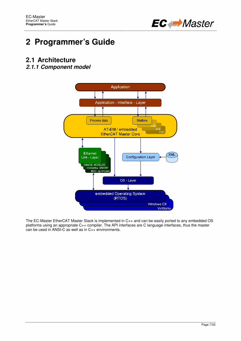
The EC-Master EtherCAT Master Stack is implemented in C++ and can be easily ported to any embedded OS platforms using an appropriate C++ compiler. The API interfaces are C language interfaces, thus the master can be used in ANSI-C as well as in C++ environments.
EC-Master
EtherCAT Master Stack Programmer’s Guide
Page 8/33
The Master Stack is divided into the following modules:
• Applications Interface Layer Interface module between the application and the EtherCAT master. If necessary the interface layer can be adjusted to fulfil the application’s requirements.
• EtherCAT Master Core In the core module cyclic (process data update) and acyclic (mailbox) EtherCAT commands are sent and received. Among others there exist some state machines to handle for example the mailbox protocols.
• Configuration Layer The EtherCAT master is configured using a XML file whose format is fixed in the EtherCAT specification. EC-Master contains an OS independent XML parser.
• Ethernet Link Layer This layer exchanges Ethernet frames between the master and the slave devices. If hard real-time requirements exist, this layer has to be optimized for the network adapter card in use. Link layer source code is available that shows how to access standard network drivers in Windows CE and VxWorks.
• OS Layer All OS dependent system calls are encapsulated in a small OS layer. Most functions are that easy that they can be implemented using simple C macros.
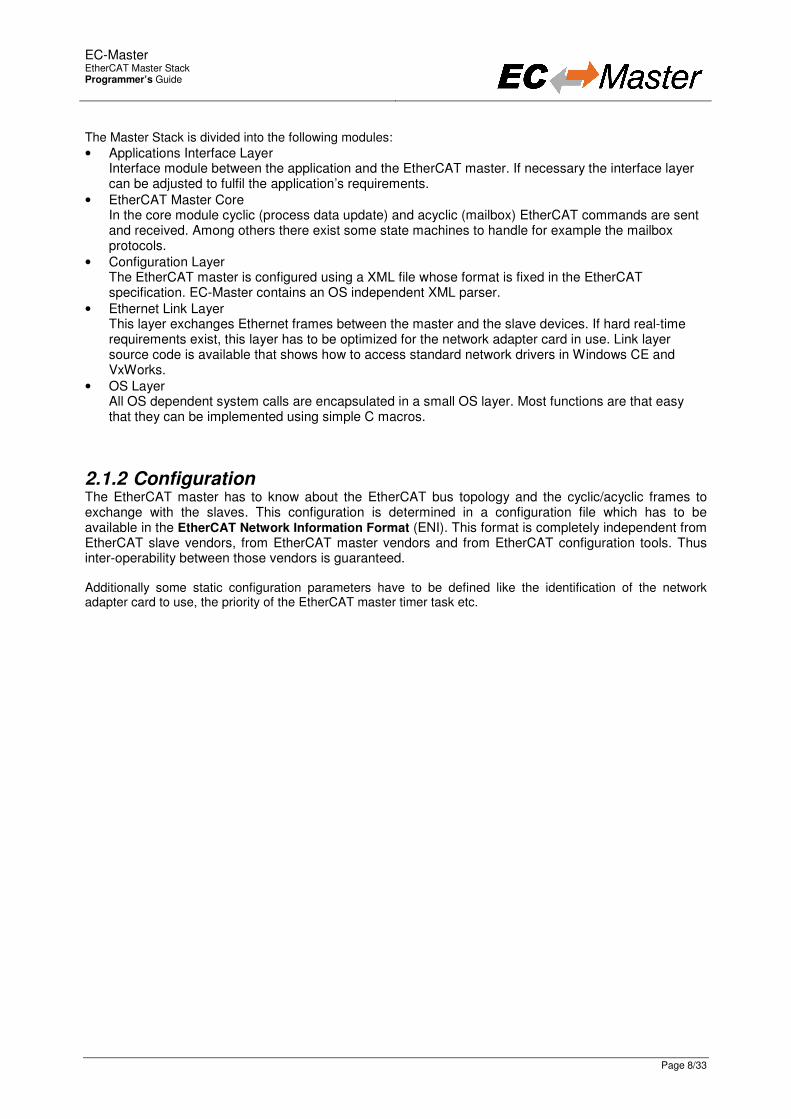
2.1.2 Configuration The EtherCAT master has to know about the EtherCAT bus topology and the cyclic/acyclic frames to exchange with the slaves. This configuration is determined in a configuration file which has to be available in the EtherCAT Network Information Format (ENI). This format is completely independent from EtherCAT slave vendors, from EtherCAT master vendors and from EtherCAT configuration tools. Thus inter-operability between those vendors is guaranteed. Additionally some static configuration parameters have to be defined like the identification of the network adapter card to use, the priority of the EtherCAT master timer task etc.

EC-Master
EtherCAT Master Stack Programmer’s Guide
Page 9/33
2.1.3 Master startup The master stack has to be initialized once when the application is starting. After this one-time initialization one or more clients may register with the master. Finally, after all clients are registered the master can be started. Starting the master means that all slaves will be set into the operational state. Every time the state of the master has changed the clients are notified about this state-change. Asynchronous (deferred) startup
Client EtherCAT-Master
EtherCAT-Master
ecatStart(EC_NOWAIT)
INIT
PREOP
SAFEOP
OPERATIONAL
ecatInitMaster()ecatConfigureMaster()
ecatNotify()
ecatNotify()
ecatNotify()
ecatNotify()
return
ecatIoCtl(REGISTERCLIENT)
1 – Client calls ecatInitMaster() 2 – Client calls ecatConfigureMaster()
3 – Client calls ecatRegisterClient() 4 – Client calls ecatStart() with a timeout parameter EC_NOWAIT 5 – Inside ecatStart() the master startup procedure will be initiated
6 – Function ecatStart() returns immediately (EC_NOWAIT) 7 – The master initializes all slaves until all slaves reach OPERATIONAL state 8 – After every state change the client will be notified
9 – After reaching the OPERATIONAL state the system is ready
1
2
4
5
6
7
8
3
EC-Master
EtherCAT Master Stack Programmer’s Guide
Page 10/33
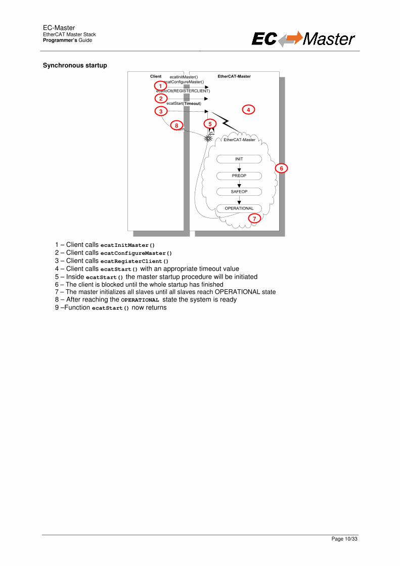
Synchronous startup
Client EtherCAT-Master
EtherCAT-Master
ecatStart(Timeout)
return
INIT
PREOP
SAFEOP
OPERATIONAL
ecatInitMaster()
ecatConfigureMaster()
ecatIoCtl(REGISTERCLIENT)
1 – Client calls ecatInitMaster() 2 – Client calls ecatConfigureMaster()
3 – Client calls ecatRegisterClient() 4 – Client calls ecatStart() with an appropriate timeout value
5 – Inside ecatStart() the master startup procedure will be initiated 6 – The client is blocked until the whole startup has finished 7 – The master initializes all slaves until all slaves reach OPERATIONAL state
8 – After reaching the OPERATIONAL state the system is ready 9 –Function ecatStart() now returns
1
2
4
5
6
8
7
3
EC-Master
EtherCAT Master Stack Programmer’s Guide
Page 11/33
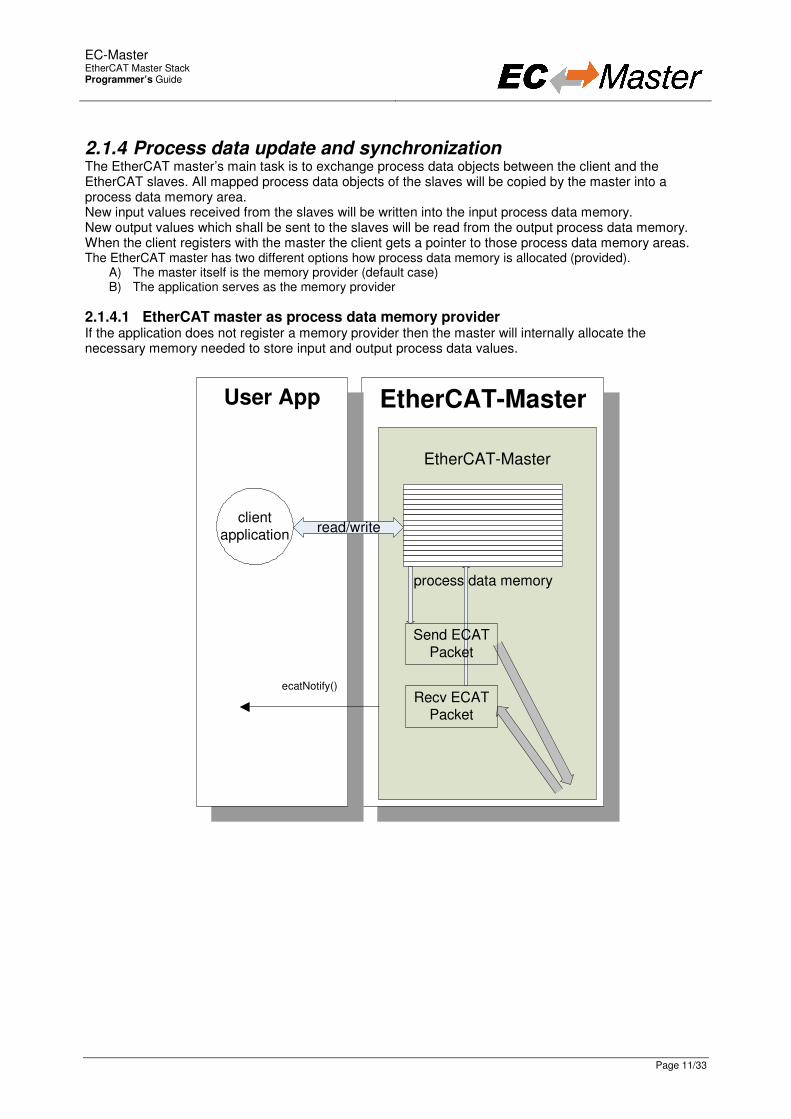
2.1.4 Process data update and synchronization The EtherCAT master’s main task is to exchange process data objects between the client and the EtherCAT slaves. All mapped process data objects of the slaves will be copied by the master into a process data memory area. New input values received from the slaves will be written into the input process data memory. New output values which shall be sent to the slaves will be read from the output process data memory. When the client registers with the master the client gets a pointer to those process data memory areas. The EtherCAT master has two different options how process data memory is allocated (provided).
A) The master itself is the memory provider (default case) B) The application serves as the memory provider
2.1.4.1 EtherCAT master as process data memory provider If the application does not register a memory provider then the master will internally allocate the necessary memory needed to store input and output process data values.
EtherCAT-Master
EtherCAT-Master
User App
ecatNotify() Recv ECAT
Packet
read/write
Send ECAT Packet
process data memory
client application

EC-Master
EtherCAT Master Stack Programmer’s Guide
Page 12/33
2.1.4.2 User application as process data memory provider The application may register a memory provider in case the master shall use externally allocated memory to store input and output process data values (Fehler! Verweisquelle konnte nicht gefunden werden.).
EtherCAT-Master
EtherCAT-Master
User App
Recv ECAT Packet
client application
output data read
synchronization
Send ECAT
Packet
input data write
synchronization
read/w
rite
The memory provider may optionally supply callback functions to synchronize memory access between the clients and the master. In this case the master’s sequence of receiving new input process data values is as follows: – new process data is received, data is internally located in the Ethernet frame buffer – master requests write access to the input process data memory (callback function
pfPDInDataWriteRequest) – master copies input data into process data memory – master releases write access (callback function pfPDInDataWriteRelease)
The master’s sequence of sending new output process data values is as follows: – Application: new process data is stored in the output process data memory buffer – Master requests read access to the output process data memory (callback function
pfPDOutDataReadRequest) – Master copies output data into the Ethernet frame – Master releases read access (callback function pfPDOutDataReadRelease) – new output process data will be sent to the slaves
EC-Master
EtherCAT Master Stack Programmer’s Guide
Page 13/33
2.1.4.3 Process data memory provider: fixed and dynamic buffers The EtherCAT master uses two separate buffers where process data input values and process data output values are stored. The buffers used may either be always the same (fixed buffers) or be changed on every process data transfer cycle (dynamic buffers). Case 1: EtherCAT master provides process data memory (fixed buffers) If the application does not call ecatIoControl - EC_IOCTL_REGISTER_PDMEMORYPROVIDER the master is used as process data memory provider. The memory will then be allocated once when the master is configured (ecatConfigureMaster). The master will always use the same buffers to read/write process data. Case 2: User application registers an external memory provider with fixed buffers When the application calls ecatIoControl - EC_IOCTL_REGISTER_PDMEMORYPROVIDER it can determine the address where the process data buffers are located. These fixed buffers will be used by the EtherCAT master to store process data. Case 3: User application registers an external memory provider without fixed buffers The application calls ecatIoControl - EC_IOCTL_REGISTER_PDMEMORYPROVIDER with setting the fixed buffer address values to EC_NULL. In this case the EtherCAT master will request the buffer addresses cyclically when process data are read or written (callback functions). This mode may be used to implement dynamic buffering mechanisms between the application and the EtherCAT master (double buffering, triple buffering).
EC-Master
EtherCAT Master Stack Programmer’s Guide
Page 14/33
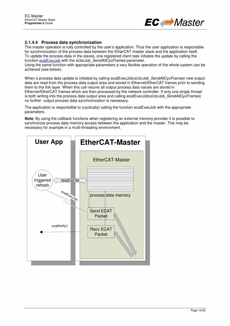
2.1.4.4 Process data synchronization The master operation is fully controlled by the user’s application. Thus the user application is responsible for synchronization of the process data between the EtherCAT master stack and the application itself. To update the process data in the slaves, one registered client task initiates the update by calling the function ecatExecJob with the eUsrJob_SendAllCycFrames parameter. Using the same function with appropriate parameters a very flexible operation of the whole system can be achieved (see below). When a process data update is initiated by calling ecatExecJob(eUsrJob_SendAllCycFrames) new output data are read from the process data output area and stored in Ethernet/EtherCAT frames prior to sending them to the link layer. When this call returns all output process data values are stored in Ethernet/EtherCAT frames which are then processed by the network controller. If only one single thread is both writing into the process data output area and calling ecatExecJob(eUsrJob_SendAllCycFrames) no further output process data synchronization is necessary.
The application is responisible to (cyclically) calling the function ecatExecJob with the appropriate parameters.
Note: By using the callback functions when registering an external memory provider it is possible to synchronize process data memory access between the application and the master. This may be necessary for example in a multi-threading environment.
EtherCAT-Master
EtherCAT-Master
User App
ecatNotify() Recv ECAT
Packet
read/write
Send ECAT Packet
process data memory
User triggered refresh
ecatExecJob

EC-Master
EtherCAT Master Stack Programmer’s Guide
Page 15/33
The master operates in a single mode called User Controlled Mode. This mode can be used in all applications, it is optimized for systems which require a tightly coupled timing, e.g. PLC with MCFB (Motion Control Function Blocks) or position control realized by the control application instead of a drive control (intelligent drive). The (user) application has to initiate each step necessary to update process data as well as for the master’s internal management. The timing of the necessary jobs within one cycle is described in the following diagram.
Master Ctrl. S
M
Master Timer
Flush Queued Cmds
Send Acyc Frames
Steps the application (PLC) has to call:
1 – eUsrJob_ProcessAllRxFrames Link layer in polling mode: process all received frames (e.g. read new input process data).
2 – eUsrJob_SendAllCycFrames Send cyclic frames to update process output data.
3 – eUsrJob_RunMcSm Trigger the higher level EtherCAT master control state machine. Among other duties this state machine is responsible for controlling the master/slave state change operation, bus-scan and several diagnostis handling.
4 – eUsrJob_MasterTimer Trigger the lower level master and slave state machines. This job has to be called cyclically. The master cycle time is determined by the period between
calling ecatExecJob(eUsrJob_MasterTimer). 5 – eUsrJob_FlushQueuedCmds
Fill pending acyclic datagrams to a Ethernet frame (regardless if the Ethernet frame would be capable to store further datagrams).
6 – eUsrJob_SendAcycFrames Transmit pending acyclic frame(s).
Note: When the link layer is running in interrupt mode processing of received frames is done immediately after the frame is received.
EC-Master
EtherCAT Master Stack Programmer’s Guide
Page 16/33
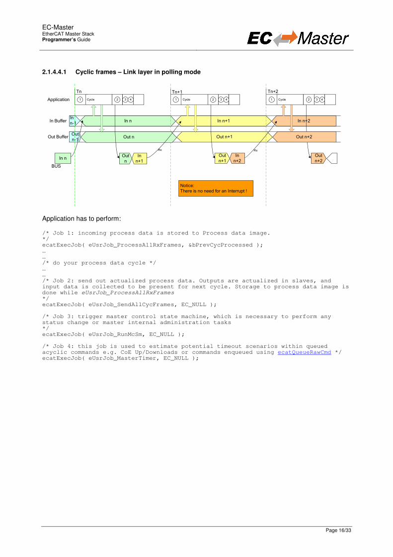
2.1.4.4.1 Cyclic frames – Link layer in polling mode
Application Cycle Cycle Cycle
Tn Tn+1 Tn+2
In Buffer
Out Buffer
BUS
In n-1
In n In n+1 In n+2
Out
n-1Out n+1
Out n
In n+1
In nOut n+1
In n+2
Out n+2
Notice:There is no need for an Interrupt !
1 2 3 4 1 2 3 4 1 2 3 4
Rx Rx
Out n Out n+2
Application has to perform: /* Job 1: incoming process data is stored to Process data image. */ ecatExecJob( eUsrJob_ProcessAllRxFrames, &bPrevCycProcessed ); … … /* do your process data cycle */ … … /* Job 2: send out actualized process data. Outputs are actualized in slaves, and input data is collected to be present for next cycle. Storage to process data image is done while eUsrJob_ProcessAllRxFrames */ ecatExecJob( eUsrJob_SendAllCycFrames, EC_NULL ); /* Job 3: trigger master control state machine, which is necessary to perform any status change or master internal administration tasks */ ecatExecJob( eUsrJob_RunMcSm, EC_NULL ); /* Job 4: this job is used to estimate potential timeout scenarios within queued acyclic commands e.g. CoE Up/Downloads or commands enqueued using ecatQueueRawCmd */ ecatExecJob( eUsrJob_MasterTimer, EC_NULL );

EC-Master
EtherCAT Master Stack Programmer’s Guide
Page 17/33
2.1.4.4.2 Cyclic and acyclic frames – Link layer in polling mode
Application
(PLC)Cycle Cycle Cycle
Tn Tn+1 Tn+2
In Buffer
Out Buffer
BUS
In
n-1In n In n+1 In n+2
Out n-1 Out n Out n+1 Out n+2
Out n In n+1In n Out n+1 In n+2 Out n+2
Acyc n Acyc Response
There may but not need to be
acyclic frames !
Notice:
There is no need for an Interrupt !
1 2 3 4 5 6 1 2 3 4 5 6 1 2 3 4 5 6
Acyc n Acyc Response
Rx
Rx
Rx
Application has to perform: /* Job 1: incoming process data is stored to Process data image. */ ecatExecJob( eUsrJob_ProcessAllRxFrames, &bPrevCycProcessed ); … … /* do your process data cycle */ … … /* Job 2: send out actualized process data. Outputs are actualized in slaves, and input data is collected to be present for next cycle. Storage to process data image is done while eUsrJob_ProcessAllRxFrames */ ecatExecJob( eUsrJob_SendAllCycFrames, EC_NULL ); /* Job 3: trigger master control state machine, which is necessary to perform any status change or master internal administration tasks */ ecatExecJob( eUsrJob_RunMcSm, EC_NULL ); /* Job 4: this job is used to estimate potential timeout scenarios within queued acyclic commands e.g. CoE Up/Downloads or commands enqueued using ecatQueueRawCmd */ ecatExecJob( eUsrJob_MasterTimer, EC_NULL ); /* Job 5: this job commits pending acyclic commands to a frame. This job should be issued before calling eUsrJob_SendAcycFrames */ ecatExecJob( eUsrJob_FlushQueuedCmds, EC_NULL ); /* Job 6: transmit queued acyclic commands, which in case can be enqueued through user application or master administrative tasks. Reponses are retrieved by issuing eUsrJob_ProcessAllRxFrames. */ ecatExecJob( eUsrJob_SendAcycFrames, EC_NULL );

EC-Master
EtherCAT Master Stack Programmer’s Guide
Page 18/33
2.1.4.4.3 Cyclic frames with DC – Link layer in polling mode
Application has to perform: /* Job 1: incoming process data is stored to Process data image. */ ecatExecJob( eUsrJob_ProcessAllRxFrames, &bPrevCycProcessed ); … /* do your process data cycle */ … /* Job 2: send out actualized process data. Outputs are actualized in slaves, and input data is collected to be present for next cycle. Storage to process data image is done while eUsrJob_ProcessAllRxFrames */ ecatExecJob( eUsrJob_SendAllCycFrames, EC_NULL ); /* Job 3: trigger master control state machine, which is necessary to perform any status change or master internal administration tasks */ ecatExecJob( eUsrJob_RunMcSm, EC_NULL ); /* Job 4: this job is used to estimate potential timeout scenarios within queued acyclic commands e.g. CoE Up/Downloads or commands enqueued using ecatQueueRawCmd */ ecatExecJob( eUsrJob_MasterTimer, EC_NULL );
EC-Master
EtherCAT Master Stack Programmer’s Guide
Page 19/33
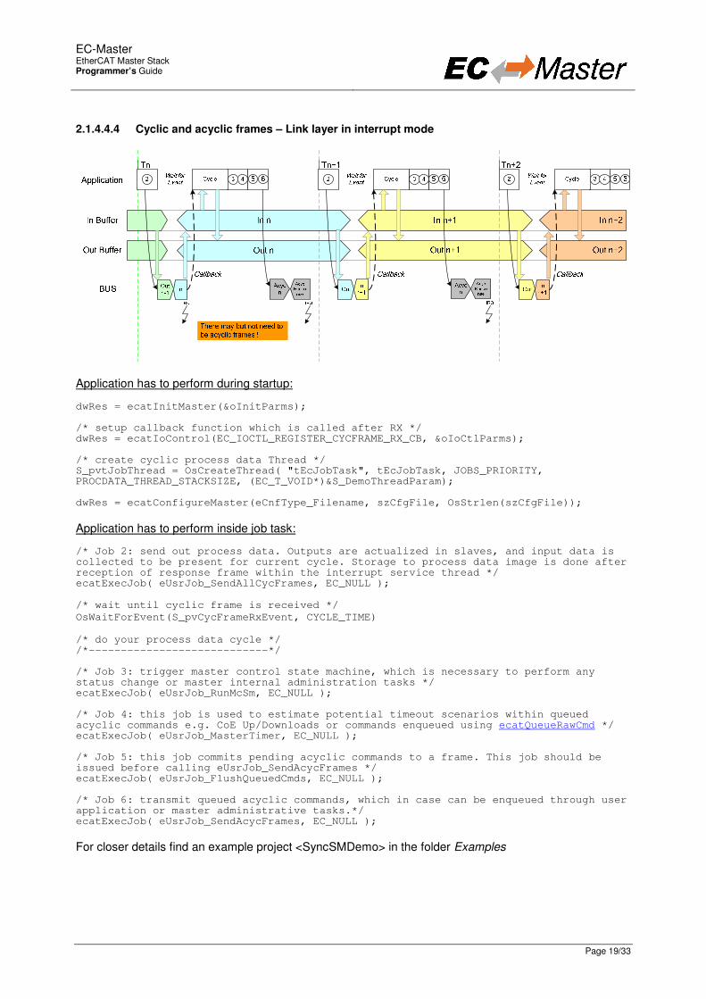
2.1.4.4.4 Cyclic and acyclic frames – Link layer in interrupt mode
Application has to perform during startup: dwRes = ecatInitMaster(&oInitParms); /* setup callback function which is called after RX */ dwRes = ecatIoControl(EC_IOCTL_REGISTER_CYCFRAME_RX_CB, &oIoCtlParms); /* create cyclic process data Thread */ S_pvtJobThread = OsCreateThread( "tEcJobTask", tEcJobTask, JOBS_PRIORITY, PROCDATA_THREAD_STACKSIZE, (EC_T_VOID*)&S_DemoThreadParam); dwRes = ecatConfigureMaster(eCnfType_Filename, szCfgFile, OsStrlen(szCfgFile));
Application has to perform inside job task: /* Job 2: send out process data. Outputs are actualized in slaves, and input data is collected to be present for current cycle. Storage to process data image is done after reception of response frame within the interrupt service thread */ ecatExecJob( eUsrJob_SendAllCycFrames, EC_NULL ); /* wait until cyclic frame is received */
OsWaitForEvent(S_pvCycFrameRxEvent, CYCLE_TIME)
/* do your process data cycle */ /*----------------------------*/ /* Job 3: trigger master control state machine, which is necessary to perform any status change or master internal administration tasks */ ecatExecJob( eUsrJob_RunMcSm, EC_NULL ); /* Job 4: this job is used to estimate potential timeout scenarios within queued acyclic commands e.g. CoE Up/Downloads or commands enqueued using ecatQueueRawCmd */ ecatExecJob( eUsrJob_MasterTimer, EC_NULL ); /* Job 5: this job commits pending acyclic commands to a frame. This job should be issued before calling eUsrJob_SendAcycFrames */ ecatExecJob( eUsrJob_FlushQueuedCmds, EC_NULL ); /* Job 6: transmit queued acyclic commands, which in case can be enqueued through user application or master administrative tasks.*/ ecatExecJob( eUsrJob_SendAcycFrames, EC_NULL );
For closer details find an example project <SyncSMDemo> in the folder Examples

EC-Master
EtherCAT Master Stack Programmer’s Guide
Page 20/33
2.1.4.5 Single or multiple cyclic entries in ENI file For reading new input data values and writing new output data values (process data update) the EtherCAT configuration file contains one or multiple “Cyclic” entries. These entries contain one or multiple frames (so-called cyclic frames) to be sent cyclically by the master. Inside the cyclic frames there are one or multiple EtherCAT datagrams containing logical read/write commands for reading and writing process data values. 2.1.4.5.1 Configuration variant 1: single cyclic entry In the simplest case there is only one single cyclic entry with one or multiple cyclic frames.
All process data synchronization modes (see Process data synchronization) support this configuration variant.

EC-Master
EtherCAT Master Stack Programmer’s Guide
Page 21/33
2.1.4.5.2 Configuration variant 2: multiple cyclic entries For more sophisticated scenarios it is possible to configure the system using multiple cyclic entries with one or multiple cyclic frames for each cyclic entry.

EC-Master
EtherCAT Master Stack Programmer’s Guide
Page 22/33
2.1.5 CanOpen over EtherCAT transfers The EtherCAT client may use these services for example to access the object dictionary of a CoE slave.
EtherCATEtherCATEtherCATEtherCAT----MasterMasterMasterMaster
EtherCAT-Master
ClientClientClientClient
ecatCoeSdoDownload()
ecatNotify()(e.g. SDO transfer response)
recv ECAT
packet
ecatCoeSdoUpload()
ecatCoeGetODList(), ecatCoeGetObjectDesc(),ecatCoeGetEntryDesc()
CoE state
machine
send ECAT
packet
The following services are supported:
• SDO download: SDO data transfer from the controller to a slave
• SDO upload: SDO data transfer from a slave to the controller
• SDO information service: read SDO object properties (object dictionary) from a slave
• Emergency Request The CoE mailbox transfer is controlled by the master timer (application needs to call ecatExecJob(eUsrJob_MasterTimer) cyclically). The client will be notified about a complete mailbox transfer using the generic ecatNotify() callback function.
2.1.6 Error detection and diagnosis One of the parameters the client has to set when registering with the EtherCAT master is a generic notification callback function (ecatNotify). In case an error is detected the master will call this function.

EC-Master
EtherCAT Master Stack Programmer’s Guide
Page 23/33
EC-Master
EtherCAT Master Stack Application framework and example application
Page 24/33
3 Application framework and example application
3.1 Overview
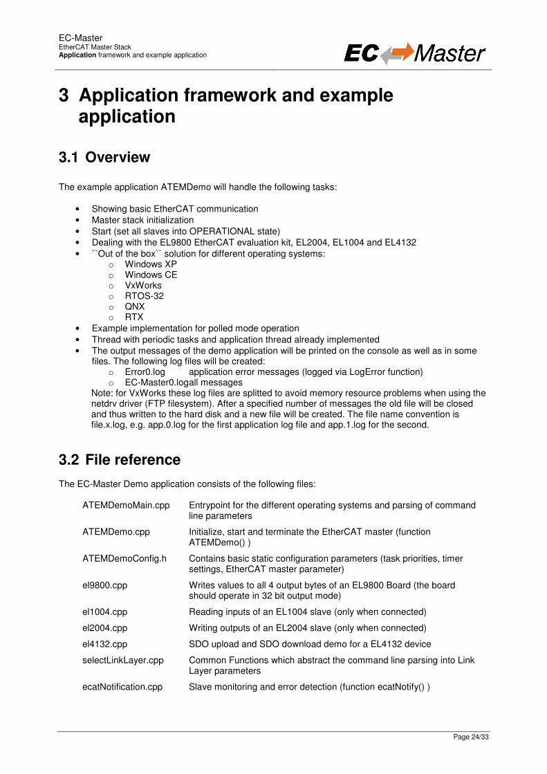
The example application ATEMDemo will handle the following tasks:
• Showing basic EtherCAT communication
• Master stack initialization
• Start (set all slaves into OPERATIONAL state)
• Dealing with the EL9800 EtherCAT evaluation kit, EL2004, EL1004 and EL4132
• ``Out of the box`` solution for different operating systems: o Windows XP o Windows CE o VxWorks o RTOS-32 o QNX o RTX
• Example implementation for polled mode operation
• Thread with periodic tasks and application thread already implemented
• The output messages of the demo application will be printed on the console as well as in some files. The following log files will be created:
o Error0.log application error messages (logged via LogError function) o EC-Master0.log all messages
Note: for VxWorks these log files are splitted to avoid memory resource problems when using the netdrv driver (FTP filesystem). After a specified number of messages the old file will be closed and thus written to the hard disk and a new file will be created. The file name convention is file.x.log, e.g. app.0.log for the first application log file and app.1.log for the second.
3.2 File reference The EC-Master Demo application consists of the following files:
ATEMDemoMain.cpp Entrypoint for the different operating systems and parsing of command line parameters
ATEMDemo.cpp Initialize, start and terminate the EtherCAT master (function ATEMDemo() )
ATEMDemoConfig.h Contains basic static configuration parameters (task priorities, timer settings, EtherCAT master parameter)
el9800.cpp Writes values to all 4 output bytes of an EL9800 Board (the board should operate in 32 bit output mode)
el1004.cpp Reading inputs of an EL1004 slave (only when connected)
el2004.cpp Writing outputs of an EL2004 slave (only when connected)
el4132.cpp SDO upload and SDO download demo for a EL4132 device
selectLinkLayer.cpp Common Functions which abstract the command line parsing into Link Layer parameters
ecatNotification.cpp Slave monitoring and error detection (function ecatNotify() )
EC-Master
EtherCAT Master Stack Application framework and example application
Page 25/33
ecatDemoCommon.cpp Class with generic helper functions; e.g. simple access to the process image or finding individual slaves connected to the EtherCAT bus.
SlaveInfo.h Slave information services (bus scan, slave properties)
Logging.cpp Message logging functions
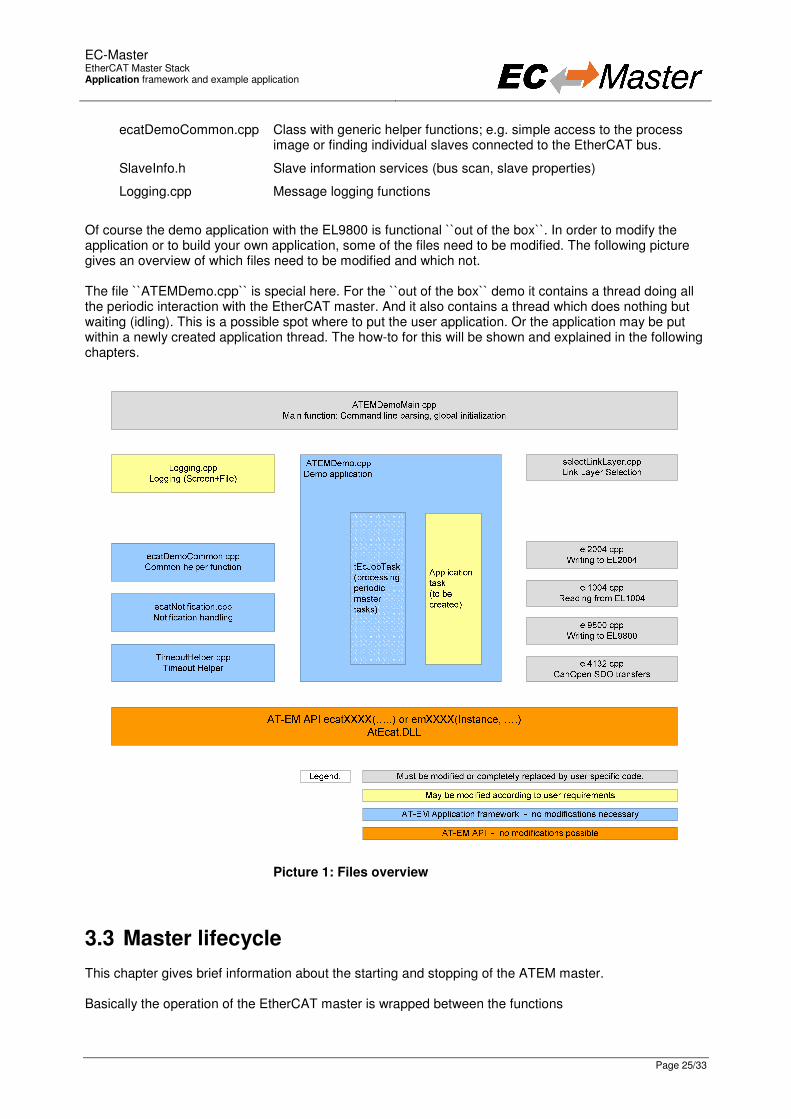
Of course the demo application with the EL9800 is functional ``out of the box``. In order to modify the application or to build your own application, some of the files need to be modified. The following picture gives an overview of which files need to be modified and which not. The file ``ATEMDemo.cpp`` is special here. For the ``out of the box`` demo it contains a thread doing all the periodic interaction with the EtherCAT master. And it also contains a thread which does nothing but waiting (idling). This is a possible spot where to put the user application. Or the application may be put within a newly created application thread. The how-to for this will be shown and explained in the following chapters.
Picture 1: Files overview
3.3 Master lifecycle This chapter gives brief information about the starting and stopping of the ATEM master. Basically the operation of the EtherCAT master is wrapped between the functions
EC-Master
EtherCAT Master Stack Application framework and example application
Page 26/33
• ecatInitMaster()
• ecatStart() and
• ecatStop()
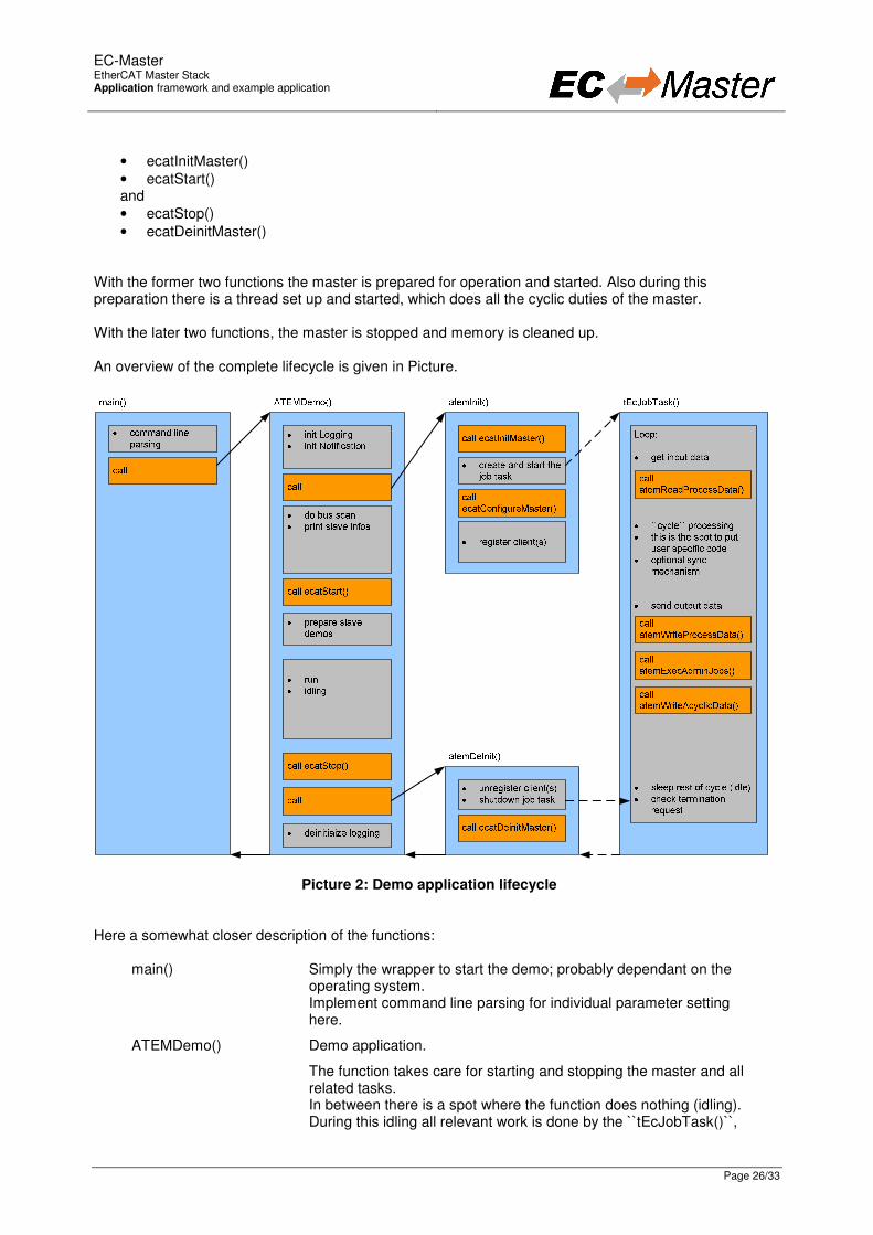
• ecatDeinitMaster() With the former two functions the master is prepared for operation and started. Also during this preparation there is a thread set up and started, which does all the cyclic duties of the master. With the later two functions, the master is stopped and memory is cleaned up. An overview of the complete lifecycle is given in Picture.
Picture 2: Demo application lifecycle Here a somewhat closer description of the functions:
main() Simply the wrapper to start the demo; probably dependant on the operating system. Implement command line parsing for individual parameter setting here.
ATEMDemo() Demo application.
The function takes care for starting and stopping the master and all related tasks. In between there is a spot where the function does nothing (idling). During this idling all relevant work is done by the ``tEcJobTask()``,
EC-Master
EtherCAT Master Stack Application framework and example application
Page 27/33
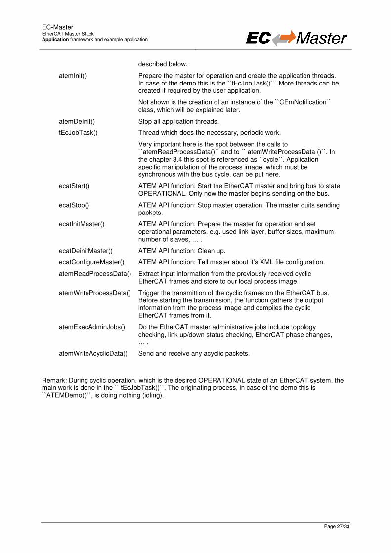
described below.
atemInit() Prepare the master for operation and create the application threads. In case of the demo this is the ``tEcJobTask()``. More threads can be created if required by the user application.
Not shown is the creation of an instance of the ``CEmNotification`` class, which will be explained later.
atemDeInit() Stop all application threads.
tEcJobTask() Thread which does the necessary, periodic work.
Very important here is the spot between the calls to ``atemReadProcessData()`` and to `` atemWriteProcessData ()``. In the chapter 3.4 this spot is referenced as ``cycle``. Application specific manipulation of the process image, which must be synchronous with the bus cycle, can be put here.
ecatStart() ATEM API function: Start the EtherCAT master and bring bus to state OPERATIONAL. Only now the master begins sending on the bus.
ecatStop() ATEM API function: Stop master operation. The master quits sending packets.
ecatInitMaster() ATEM API function: Prepare the master for operation and set operational parameters, e.g. used link layer, buffer sizes, maximum number of slaves, … .
ecatDeinitMaster() ATEM API function: Clean up.
ecatConfigureMaster() ATEM API function: Tell master about it’s XML file configuration.
atemReadProcessData() Extract input information from the previously received cyclic EtherCAT frames and store to our local process image.
atemWriteProcessData() Trigger the transmittion of the cyclic frames on the EtherCAT bus. Before starting the transmission, the function gathers the output information from the process image and compiles the cyclic EtherCAT frames from it.
atemExecAdminJobs() Do the EtherCAT master administrative jobs include topology checking, link up/down status checking, EtherCAT phase changes, … .
atemWriteAcyclicData() Send and receive any acyclic packets.
Remark: During cyclic operation, which is the desired OPERATIONAL state of an EtherCAT system, the main work is done in the `` tEcJobTask()``. The originating process, in case of the demo this is ``ATEMDemo()``, is doing nothing (idling).

EC-Master
EtherCAT Master Stack Application framework and example application
Page 28/33
3.4 Synchronisation This chapter puts the tasks or functions, which run in the `` tEcJobTask()``, into relation with timing and communication on the EtherCAT bus. See Picture.
Picture 3: Synchronisation
Application Shown are the tasks/jobs (1) through (6) which must be done by the application every single cycle. The details of the individual tasks are described below.
When the application is through with the tasks, it may be idling (period between (6) and (1)).
In buffer Shown are the contents of the input section of the process image. The contents are not valid while the EtherCAT master updates the data (1).
Out buffer Shown are the contents of the output section of the process image. The contents are not valid while the application updates the data (1).
EtherCAT bus Shown are the timing positions, when the EtherCAT master does cyclic and acyclic communication on the EtherCAT bus. Besides the timing position of the start for the cyclic frames, the shown positions may vary, depending on the number of frames.
In the ``ATEMDemo()`` application the tasks/jobs (1) through (6) shown in the picture are managed and scheduled by the `` tEcJobTask()``. Here a more detailed description:
Job 1 atemReadProcessData()
This function works on the frames and data received with previous bus activity. This includes cyclic as well as acyclic frames.
The received frames are analysed for new input data and the local process image is updated. During this process the input data section of the process image is invalid.
cycle In the current ATEMDemo(): Call ELxxxx() slave functions.
This is the spot where a user defined application can manipulate the process image.
EC-Master
EtherCAT Master Stack Application framework and example application
Page 29/33
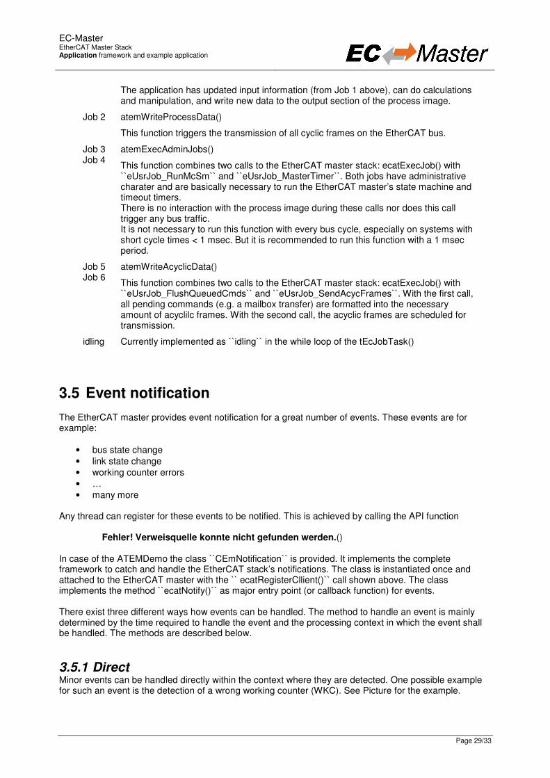
The application has updated input information (from Job 1 above), can do calculations and manipulation, and write new data to the output section of the process image.
Job 2 atemWriteProcessData()
This function triggers the transmission of all cyclic frames on the EtherCAT bus.
Job 3 Job 4
atemExecAdminJobs()
This function combines two calls to the EtherCAT master stack: ecatExecJob() with ``eUsrJob_RunMcSm`` and ``eUsrJob_MasterTimer``. Both jobs have administrative charater and are basically necessary to run the EtherCAT master’s state machine and timeout timers. There is no interaction with the process image during these calls nor does this call trigger any bus traffic. It is not necessary to run this function with every bus cycle, especially on systems with short cycle times < 1 msec. But it is recommended to run this function with a 1 msec period.
Job 5 Job 6
atemWriteAcyclicData()
This function combines two calls to the EtherCAT master stack: ecatExecJob() with ``eUsrJob_FlushQueuedCmds`` and ``eUsrJob_SendAcycFrames``. With the first call, all pending commands (e.g. a mailbox transfer) are formatted into the necessary amount of acyclilc frames. With the second call, the acyclic frames are scheduled for transmission.
idling Currently implemented as ``idling`` in the while loop of the tEcJobTask()
3.5 Event notification The EtherCAT master provides event notification for a great number of events. These events are for example:
• bus state change
• link state change
• working counter errors
• …
• many more Any thread can register for these events to be notified. This is achieved by calling the API function Fehler! Verweisquelle konnte nicht gefunden werden.() In case of the ATEMDemo the class ``CEmNotification`` is provided. It implements the complete framework to catch and handle the EtherCAT stack’s notifications. The class is instantiated once and attached to the EtherCAT master with the `` ecatRegisterCllient()`` call shown above. The class implements the method ``ecatNotify()`` as major entry point (or callback function) for events. There exist three different ways how events can be handled. The method to handle an event is mainly determined by the time required to handle the event and the processing context in which the event shall be handled. The methods are described below.
3.5.1 Direct Minor events can be handled directly within the context where they are detected. One possible example for such an event is the detection of a wrong working counter (WKC). See Picture for the example.

EC-Master
EtherCAT Master Stack Application framework and example application
Page 30/33
Picture 4: Direct event handling Here event handling is reduced to simply issuing a ``LogError()`` message, which is not time critical. The event is handled directly within the context of the ``atemReadProcessData()`` function.
3.5.2 Queue Events which require more time consuming processing can not be handled directly in the context where they are detected. Handling or processing of the event must be postponed. This is achieved by a queue, which is also readily implemented with the ``CEmNotification`` class. Picture shows an example for this behavior.
ATEMDemo.cpp ecatNotification.cpp
atemReadProcessData():
� processing received
frames
� e.g. scan bus finished
� create notification
� continue frame
processing
Master Core
call ecatNotify()
ecatNotify():
� process notification
(switch/case)
� put to notification
queue
� done notification
processing
tEcJobTask():
� process received
frames
� proceed job task
processing
� process notifications
call
atemReadProcessData()
notification
queue
call ProcessNotificationJobs()
ProcessNotificationJobs():
� get notification from
queue
� process notification
(switch/case)
� done notification
processing
Picture 5: Postponed (or queued) event handling
EC-Master
EtherCAT Master Stack Application framework and example application
Page 31/33
The job task periodically checks the event queue for events which must be handled. This is done via the simple call to ``CEmNotification::ProcessNotificationJobs()``. When there is an event in the queue, it is handled during this call, which is within the context of the job task. Important: The call to CEmNotification::ProcessNotificationJobs() shall NOT be executed in the tEcJobTask(). As the CPU time consumption may be high, this would have a high impact to the real-time behavior of the cyclic operation.
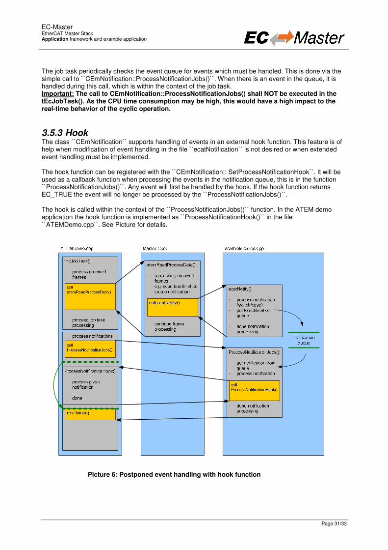
3.5.3 Hook The class ``CEmNotification`` supports handling of events in an external hook function. This feature is of help when modification of event handling in the file ``ecatNotification`` is not desired or when extended event handling must be implemented. The hook function can be registered with the ``CEmNotification:: SetProcessNotificationHook``. It will be used as a callback function when processing the events in the notification queue, this is in the function ``ProcessNotificationJobs()``. Any event will first be handled by the hook. If the hook function returns EC_TRUE the event will no longer be processed by the ``ProcessNotificationJobs()``. The hook is called within the context of the ``ProcessNotificationJobs()`` function. In the ATEM demo application the hook function is implemented as ``ProcessNotificationHook()`` in the file ``ATEMDemo.cpp``. See Picture for details.
Picture 6: Postponed event handling with hook function

EC-Master
EtherCAT Master Stack Application framework and example application
Page 32/33
3.6 File logging There are several functions which log information into files. In case the VxWorks netDrv driver is used (e.g. when accessing the PC hard disk via FTP) the content of these files is stored in memory. These files will be closed only when the application terminates or when the specified number of messages to be stored in a single file is exceeded. There are no means to limit the amount of memory needed for those files. If you extend the duration of the demo and the number of messages to be stored in the log file is too high it may occur that there is no free memory available and thus the system to crash. Using the InitLogging() function the application can determine the rollover parameter when a new log file shall be created. The file logging for VxWorks is disabled by default. Setting the global variable bLogFileEnb to a value of 1 the file logging is enabled.
3.7 Master stack debug messages Every time the EtherCAT master stack detects an error it calls the OS-Layer function OsDbgMsg(). This message usually prints out a message on the standard output device. The demo application registers a hook OsDbgMsgHook() to be called by OsDbgMsg(). The hook will store those messages into a log file (ecat.log). The hook then returns the value EC_TRUE which means that OsDbgMsg() will send the message to the standard output device. This hook should always return EC_FALSE due to performance issues. If returned EC_TRUE in OsDbgMsgHook() the master stack will block while the message is sent to the standard output device.
EC-Master
EtherCAT Master Stack Evaluation Versions
Page 33/33
4 Evaluation Versions
4.1 Windows XP With this evaluation version the functionality of the EtherCAT master can be analyzed on a Windows XP system. Using the WinPcap based filter driver it is possible to attach EtherCAT modules to any network card supported by Windows XP.
4.2 VxWorks With this evaluation version the functionality of the EtherCAT master can be analyzed on a VxWorks system. Using the SNARF filter driver it is possible to attach EtherCAT modules to any network card supported by VxWorks.
4.3 Windows CE With this evaluation version the functionality of the EtherCAT master can be analyzed on a Windows CE system with several network cards.
4.4 On Time RTOS-32 With this evaluation version the functionality of the EtherCAT master can be analyzed on a On Time RTOS-32 system with serveral network cards.
4.5 QNX Neutrino With this evaluation version the functionality of the EtherCAT master can be analyzed on QNX system with an Intel Pro/1000 network or Intel Pro/100 card.
4.6 RTX With this evaluation version the functionality of the EtherCAT master can be analyzed on RTX system with an Intel Pro/1000 network, Intel Pro/100.
4.7 Restrictions of the evaluation version • Only EtherCAT configurations with 10 slave devices in addition to the bus coupler and terminal
adapter are supported (12 slaves).
• Sending Ethernet frames terminates after 30 minutes. Afterwards timeout errors will occur.