2010,2012 Cover 07 - Bush Hog · 2010/2012 Rotary Cutter ... 1-1 Introduction.....7 1-2 Description...
24
ASSEMBLY l OPERATION l MAINTENANCE 05/09 Rev.1 $4.00 50044275 2010/2012 Rotary Cutter Operator’s Manual BUSH HOG ®
Transcript of 2010,2012 Cover 07 - Bush Hog · 2010/2012 Rotary Cutter ... 1-1 Introduction.....7 1-2 Description...

ASSEMBLY ll OPERATION ll MAINTENANCE05/09 Rev.1 $4.00 50044275
2010/2012Rotary CutterOOppeerraattoorr’’ss MMaannuuaall
BUSH HOG®

CONGRATULATIONS!You have invested in the best implement of its type on the market today.
The care you give your Bush Hog implement will greatly determine your satisfaction withits performance and its service life. We urge a careful study of this manual to provide youwith a thorough understanding of your new implement before operating, as well as sug-gestions for operation and maintenance.
If your manual should become lost or destroyed, Bush Hog will be glad to provide you witha new copy. Order from Bush Hog, 2501 Griffin Ave., Selma, Alabama, 36703. Most of ourmanuals can also be downloaded from our website at www.bushhog.com.
As an authorized Bush Hog dealer, we stock genuine Bush Hog parts which are manufac-tured with the same precision and skill as our original equipment. Our trained service per-sonnel are well informed on methods required to service Bush Hog equipment, and areready and able to help you.
Should you require additional information or assistance, please contact us.
YOUR AUTHORIZEDBUSH HOG DEALER
BECAUSE BUSH HOG MAINTAINS AN ON GOINGPROGRAM OF PRODUCT IMPROVEMENT, WERESERVE THE RIGHT TO MAKE IMPROVEMENTS IN DESIGN OR CHANGES IN SPECIFICATIONS WITH-OUT INCURRING ANY OBLIGATION TO INSTALLTHEM ON UNITS PREVIOUSLY SOLD.
BECAUSE OF THE POSSIBILITY THAT SOME PHO-TOGRAPHS IN THIS MANUAL WERE TAKEN OF PRO-TOTYPE MODELS, PRODUCTION MODELS MAYVARY IN SOME DETAIL. IN ADDITION, SOME PHO-TOGRAPHS MAY SHOW SHIELDS REMOVED FORPURPOSES OF CLARITY. NEVER OPERATE THISIMPLEMENT WITHOUT ALL SHIELDS IN PLACE.

2010/2012 SERIES ROTARY CUTTERSTABLE OF CONTENTS
SECTION/PARA PAGEWarranty ................................................2Dealer Preparation Check List ...............3Safety Alert Symbols..............................4Safety Precautions.................................5Federal Laws and Regulations ..............6
I. INTRODUCTION & DESCRIPTION ......71-1 Introduction ......................................71-2 Description.......................................7
II. PREPARATION FOR USE ....................82-1 Attaching To Tractor (Lift Models &
Semi-Mount Models .........................82-2 Attaching To Tractor (Pull Models) ..9
III.OPERATING INSTRUCTIONS............113-1 General Safety...............................113-2 Transporting...................................113-3 Adjusting Cutting Height ................113-4 Operation .......................................11
SECTION/PARA PAGEIV.MAINTENANCE..................................124-1 Maintenance Check List ................124-2 Lubrication .....................................124-3 Blade Replacement .......................134-4 Gearbox Removal..........................134-5 Gearbox Installation.......................144-6 Slip Clutch Operational Check.......144-7 Slip Clutch Adjustment..................144-8 Troubleshooting ............................15
V. ASSEMBLY.........................................155-1 Lift Models.....................................165-2 Semi-Mount Hitch Models.............275-3 Safety Chain Installation ...............175-4 Rear Band Installation...................185-5 Front Belting..................................185-6 Safety Tow Chain..........................185-7 Pull Model Assembly.....................19
Safety Decals ................................20Torque Specifications....................21
RETAIL CUSTOMER’S RESPONSIBILITYUNDER THE BUSH HOG WARRANTY
It is the Retail Customer and/or Operator’s responsibility to read the Operator’s Manual, tooperate, lubricate, maintain and store the product in accordance with all instructions andsafety procedures. Failure of the operator to read the Operator’s Manual is a misuse of thisequipment.
It is the Retail Customer and/or Operator’s responsibility to inspect the product and to haveany part(s) repaired or replaced when continued operation would cause damage or exces-sive wear to other parts or cause a safety hazard.
It is the Retail Customer’s responsibility to deliver the product to the authorized Bush HogDealer, from whom he purchased it, for service or replacement of defective parts which arecovered by warranty. Repairs to be submitted for warranty consideration must be made with-in forty-five (45) days of failure.
It is the Retail Customer’s responsibility for any cost incurred by the Dealer for traveling to orhauling of the product for the purpose of performing a warranty obligation or inspection.
1

LIMITED WARRANTYOOOOOOOOOOOOOOOOOOOOOOOOOOOOOOO
Bush Hog warrants to the original purchaser of any new Bush Hog equipment, purchased from anauthorized Bush Hog dealer, that the equipment be free from defects in material and workmanship for a periodof one (1) year for non-commercial, state, and municipalities’ use and ninety (90) days for commercial use fromdate of retail sale. The obligation of Bush Hog to the purchaser under this warranty is limited to the repair orreplacement of defective parts.
Replacement or repair parts installed in the equipment covered by this limited warranty are warrantedfor ninety (90) days from the date of purchase of such part or to the expiration of the applicable new equip-ment warranty period, whichever occurs later. Warranted parts shall be provided at no cost to the user at anauthorized Bush Hog dealer during regular working hours. Bush Hog reserves the right to inspect any equip-ment or parts which are claimed to have been defective in material or workmanship.
DISCLAIMER OF IMPLIED WARRANTIES & CONSEQUENTIAL DAMAGES
Bush Hog’s obligation under this limited warranty, to the extent allowed by law, is in lieu of all war-ranties, implied or expressed, INCLUDING IMPLIED WARRANTIES OF MERCHANTABILITY AND FITNESSFOR A PARTICULAR PURPOSE and any liability for incidental and consequential damages with respect tothe sale or use of the items warranted. Such incidental and consequential damages shall include but not belimited to: transportation charges other than normal freight charges; cost of installation other than costapproved by Bush Hog; duty; taxes; charges for normal service or adjustment; loss of crops or any other loss ofincome; rental of substitute equipment, expenses due to loss, damage, detention or delay in the delivery ofequipment or parts resulting from acts beyond the control of Bush Hog.
THIS LIMITED WARRANTY SHALL NOT APPLY:
1. To vendor items which carry their own warranties, such as engines, tires, and tubes.
2. If the unit has been subjected to misapplication, abuse, misuse, negligence, fire or other accident.
3. If parts not made or supplied by Bush Hog have been used in connection with the unit, if, in the sole judge-ment of Bush Hog such use affects its performance, stability or reliability.
4. If the unit has been altered or repaired outside of an authorized Bush Hog dealership in a mannerwhich, in the sole judgement of Bush Hog, affects its performance, stability or reliability.
5. To normal maintenance service and normal replacement items such as gearbox lubricant, hydraulic fluid, worn blades, or to normal deterioration of such things as belts and exterior finish due to use or exposure.
6. To expendable or wear items such as teeth, chains, sprockets, belts, springs and any other items that in thecompany’s sole judgement is a wear item.
NO EMPLOYEE OR REPRESENTATIVE OF BUSH HOG IS AUTHORIZED TO CHANGE THIS LIMITEDWARRANTY IN ANY WAY OR GRANT ANY OTHER WARRANTY UNLESS SUCH CHANGE IS MADE INWRITING AND SIGNED BY BUSH HOG’S SERVICE MANAGER, 2501 GRIFFIN AVE., SELMA, ALABAMA36703.
OOOOOOOOOOOOOOOOOOOOOOOOOOOOOOO
Record the model number, serial number and datepurchased. This information will be helpful to yourdealer if parts or service are required.
MAKE CERTAIN THE WARRANTY HAS BEENFILED WITH BUSH HOG / SELMA, ALABAMA .
MODEL NUMBER
SERIAL NUMBER
DATE OF RETAIL SALE
2

DEALER PREPARATION CHECK LIST
2010 / 2012 SERIES ROTARY CUTTERS
BEFORE DELIVERING MACHINE — The following check list should be completed.Use the Operator’s Manual as a guide.
r 1. Assembly completed.
r 2. Gearbox filled with oil.
r 3. All fittings lubricated.
r 4. All shields in place and in good condition.
r 5. All fasteners torqued to specifications given in Torque Chart.
r 6. Slip clutches have been checked for proper operation.
r 7. All decals in place and readable. (See decal page.)
r 8. Overall condition good (i.e. paint, welds)
r 9. Operators manual has been delivered to owner and he has been instructedon the safe and proper use of the cutter.
r 10. Warranty information registered with Bush Hog.
r 11. Purchaser or dealer elects to delete deflectors. (front chains)
Explanation:
Dealer’sSignature
Purchaser’sSignature
THIS CHECKLIST TO REMAIN IN OWNER’S MANUALIt is the responsibility of the dealer to complete the procedures listed
above before delivery of this implement to the customer.
WARNINGDeflector kit or chain shielding is standard equipment. Must be used for all non-agri-cultural uses or in areas where the possibility of thrown objects could be hazardous topersons or property. Use 5/16” double row highway chains for all roadside mowingoperations.
3

Safety Alert SymbolThis Safety Alert Symbol means: “ATTENTION! BECOME ALERT!YOUR SAFETY IS INVOLVED!”
This symbol is used to call attention to safetyprecautions that should be followed by theoperator to avoid accidents. When you see thissymbol, carefully read the message that followsand heed its advice. Failure to comply withsafety precautions could result in death or seri-ous bodily injury.
Safety Signs Signal WordsThe signal words DANGER, WARNING, AND CAUTION are used on the equipment safety signs. These wordsare intended to alert the viewer to the existence and the degree of hazard seriousness.
This signal word indicates a potentially hazardous situationwhich, if not avoided, will result in death or serious injury.
White letters on RED
This signal word indicates a potentially hazardous situationwhich, if not avoided, could result in death or serious injury
It may also be used to alert against unsafe practices.
Black letters on ORANGE
This signal word indicates a potentially hazardous situation existwhich, if not avoided, may result in minor or moderate injury.
It may also be used to alert against unsafe practices.
Black letters on YELLOW
4

IMPORTANT SAFETY PRECAUTIONSThis symbol is used to call attention to safetyprecautions that should be followed by theoperator to avoid accidents. When you see thissymbol, carefully read the message that followsand heed its advice. Failure to comply with safe-ty precautions could result in serious bodilyinjury.
In addition to the design and configuration of equipment, hazard control and accident prevention are dependentupon the awareness, concern, prudence and proper training of personnel in the operation, transport, maintenanceand storage of equipment. Lack of attention to safety can result in accident, personal injury, reduction of efficiencyand worst of all—loss of life. Watch for safety hazards and correct deficiencies promptly. Use the following safetyprecautions as a general guide to safe operations when using this machine. Additional safety precautions areused throughout this manual for specific operating and maintenance proce-dures. Read this manual and reviewthe safety precautions often until you know the limitations.
1. Read the Operator’s Manual. Failure to read the Operator’s Manual is considered a misuse of this equipment.
2. Become familiar with all the machine’s controls and all the caution, warning and danger decals affixed to the machine before attempting to start or operate.
3. Before starting or operating the machine, make a walk around inspection and check for obvious defects such as loose mounting bolts and damaged components. Correct any deficiency before starting.
4. Do not allow children to operate the cutter. Do not allow adults to operate it without proper instruction.
5. Do not carry passengers.
6. Keep the area of operation clear of all persons, particularly small children and pets. The operator should cease mowing whenever anyone comes within the operating area.
7. Clear the work area of objects which might be picked up and thrown.
8. Use a piece of cardboard or wood rather than hands to search for hydraulic leaks. Escaping hydraulic oil under pressure can penetrate skin. If fluid is injected into the skin, it must be surgically removed within a few hours by a doctor familiar with this form of injury or gangrene may result.
9. Do not operate without all guards and shields in place and in good condition.
10. Lower implement to ground, stop tractor engine, apply parking brake, and allow blades to completely stop before leaving the tractor.
11. Keep hands and feet away from blades.
12. This cutter is not to be operated along highways or in any area where people may be present unless all sides of the unit are enclosed by permanent bands, safety chains or other factory approved safety shields that are in good repair.
13. Wear personal protective equipment such as, but not limited to, protection for eyes, ears, feet, hands and head when operating or repairing the equipment. Do not wear loose clothing or jewelry that may catch on equipment moving parts.
14. When performing adjustments or maintenance on the cutter, first lower it to the ground or block it securely at a workable height.
15. Never stand between tractor and cutter while tractor is being backed to the cutter hitch.
16. Reduce speed when transporting cutter to avoid bouncing and momentary loss of steering.
17. Use tractor flashing warning lights, day or night, when transporting cutter on road or highways unlessprohibited by law.
18. In the event that someone other than yourself will operate this equipment we firmly suggest that all SAFETY references be discussed prior to operation.
19. It is recommended that tractor be equipped with Rollover Protective System (ROPS) and seat belt be used in all mowing operations.
5
IMPORTANT FEDERAL LAWS AND REGULATIONS* CONCERNINGEMPLOYERS, EMPLOYEES AND OPERATIONS.
*(This section is intended to explain in broad terms the concept and effect of the following federal laws andregulations. It is not intended as a legal interpretation of the laws and should not be considered as such).
U.S. Public Law 91-596 (The Williams-Steiger Occupational and Health Act of 1970) OSHA
This Act Seeks:“...to assure so far as possible every working man and woman in the nation safe and healthful workingconditions and to preserve our human resources...”
DUTIESSec. 5 (a) Each employer—(1) shall furnish to each of his employees employment and a place of employment
which are free from recognized hazards that are causing or are likely to causedeath or serious physical harm to his employees;
(2) shall comply with occupational safety and health standards promulgated underthis Act.(b) Each employee shall comply with occupational safety and health standards
and all rules, regulations and orders issued pursuant to this Act which areapplicable to his own actions and conduct.
OSHA RegulationsCurrent OSHA regulations state in part: “At the time of initial assignment and at least annually thereafter, theemployer shall instruct every employee in the safe operation and servicing of all equipment with which theemployee is, or will be involved.” These will include (but are not limited to) instructions to:
Keep all guards in place when the machine is in operation;
Permit no riders on equipment;
Stop engine, disconnect the power source, and wait for all machine movement to stop before servicing, adjusting, cleaning or unclogging the equipment, except where the machine must berunning to be properly serviced or maintained, in which case the employer shall instruct employeesas to all steps and procedures which are necessary to safely service or maintain the equipment.
Make sure everyone is clear of machinery before starting the engine, engaging power, or operating the machine.
Child Labor Under 16 Years OldSome regulations specify that no one under the age of 16 may operate power machinery. It is yourresponsibility to know what these regulations are in your own area or situation. (Refer to U.S. Dept. ofLabor, Employment Standard Administration, Wage & Home Division, Child Labor Bulletin #102.)
EMPLOYEE TRACTOR OPERATING INSTRUCTIONS:
1. Securely fasten your seat belt if the tractor has a ROPS.
2. Where possible, avoid operating the tractor near ditches, embankments, and holes.
3. Reduce speed when turning, crossing slopes, andon rough, slick, or muddy surfaces.
4. Stay off slopes too steep for safe operation.
5. Watch where you are going, especially at row ends, on roads, and around trees.
6. Do not permit others to ride.
7. Operate the tractor smoothly - no jerky turns, starts, or stops.
8. Hitch only to the drawbar and hitch points recom-mended by tractor manufacturers.
9. When tractor is stopped, set brakes securely and use park lock if available.
6

7
SECTION IINTRODUCTION AND DESCRIPTION
1-1 INTRODUCTION
We are pleased to have you as a Bush Hog cus-tomer. Your Model 2010/2012 Series Rotary Cutterhas been carefully designed to give maximum ser-vice with minimum down time. This manual is provid-ed to give you the necessary operating and mainte-nance instructions for keeping your rotary cutter intop operating condition. Please read this manualthoroughly. Understand what each control is for andhow to use it. Observe all safety precautionsdecaled on the machine and noted throughout themanual for safe operation of implement. If any assis-tance or additional information is needed, contactyour authorized Bush Hog dealer.
NOTEAll references made to right, left, front, rear, top orbottom is as viewed facing the direction of travel withimplement properly attached to tractor.
1-2 DESCRIPTION
The Model 2010/2012 Series Rotary Cutters, Figure1-1, are medium duty implements designed for cut-ting stalks, pasture clipping and other large, main-tained acreages. Free swinging uplift blades provide
a smooth, even cut and will swing back when a sta-tionary object is hit. A slip clutch on the input drive-line and rubber couplings on the cross shafts alsodampen the impact of the blades hitting a stationaryobject. Shock absorbing rubber cushions are mount-ed between the axle arm and axle arm mountingbracket to reduce shock loads during operation andtransporting. These cutters are available with eitherpull, semi-mount, or three point hitches.
Table 1-1 Specifications2010 2012
Length (Pull) 147 in. 160 in.Length (Lift) 108 in. 120 in.Width 123 in. 146 in.Cutting Width 117 in. 141 in.Cutting Height 2-12 in. 2-12 in.Minimum Tractor HP(Pull & Semi) 40 50(Lift) 60 70
Blade Tip Speed @ 540 rpm 15777 ft./min. 15490 ft./min.@1000 rpm 15708 ft./min. 15422 ft./min.
*Approx Weight (Pull) 2165 lbs. 2513 lbs.*Approx Weight (Semi) 1817 lbs. 2120 lbs.*Approx Weight (Lift) 1922 lbs 2225 lbs.
*Unit equipped with front belting and rear bands
2012 Pull Typewith Light Kit
2012 Lift Type
Figure 1-1

8
SECTION IIPREPARATION FOR USE
2-1 ATTACHING TO TRACTORLift & Semi-Mount
IMPORTANTThe minimum recommended horsepower for operat-ing a lift model 2010 cutter is 60 and for a semi-mount model is 40. The minimum recommendedhorsepower for model 2012 lift models is 70 and fora semi-mount is 50.
A. Attach cutter to tractor 3-point hitch asdescribed in tractor operator’s manual. Arrangebushings on hitch pins as shown in Figure 2-1 toaccomodate different size hitches.
Figure 2-1 Lift Pin Bushing
NOTEDue to the many variations in tractor/implementhitch points and corresponding differences indistances between tractor PTO shafts andimplement input shafts, drivelines may need tobe shortened as described in the following steps.
WARNINGNEVER STAND BETWEEN TRACTOR ANDCUTTER WHILE TRACTOR IS BEINGBACKED TO HITCH
ADDITIONAL TRACTOR FRONT BALLASTMAY BE NEEDED FOR STABLE OPERA-TION AND TRANSPORT OF CUTTER. SEETRACTOR OPERATORS MANUAL FORRECOMMENDED WEIGHTS. USE ROPS(ROLLOVER PROTECTIVE STRUCTURE)AND SEATBELT EQUIPPED TRACTORSFOR MOWING OPERATIONS. BUCKLE UPSEAT BELT TO AVOID ACCIDENTAL FALLAND POSSIBLE INJURY FROM CUTTER.
WARNING
Cat. III Std.Cat.II Std.Cat. III Quick
Cat. II Quick
Cat. II QuickCat. III Std.
Cat. III Quick
Cat. II Std.
NOTEMove bolt and bushing to
middle hole forCat. III Quick Hitch
B. Raise and lower cutter to dettermine positionwith shortest distance between the tractor PTO shaftand gearbox input shaft.shut down tractor leavingcutter in position of shortest distance. SECURELYBLOCK CUTTER IN POSITION.
C. Pull driveline apart. Attach outer (female) sec-tion to tracator PTO shaft. Pull on driveline section tobe sure yoke locks into place.
D. Hold driveline sections paralled to each otherto determine if too long. Each section should endapproximately 3 inches (76mm) short of reachinguniversal joint shield mark on opposite section.(Figure 2-2) Do this for both sections.
E. Raise and lower cutter to determine positionwith greatest distance between PTO shaft and gear-box input shaft. Shut down tractor leaving cutter inposition of greatest distance. SECURELY BLOCKCUTTER IN POSITION.
F. Hold driveline sections parallel to each otherand check for minimum 6 inches (152mm) overlap.(Figure 2-3) If driveline has been marked for cutting,overlap will be the distance between two marks. Ifdriveline has less than minimum overlap, DO NOTUSE. Contact authorized Bush Hog dealer.
NOTEIf driveline is correct length, omit steps “G” through“J” and proceed to step “K”.
Figure 2-2 Marking Shield
Figure 2-3
Minimum Overlap

9
Figure 2-4 Cutting Shield
Figure 2-5 Cutting Shaft
Figure 2-6 Deburring
G. Clamp driveline in a padded vice to preventdamage to shield. Cut off shield where marked.(Figure 2-4)
H. Using cut off section of shield as a guide, cutshaft the same amount . (Figure 2-5)
I. Repeat steps “G” and “H” to other drivelinesection.
J. Deburr ends of driveline sections and cleanaway all chips and filings. (Figure 2-6)
K. Apply multi-purpose grease to outside of maledriveline section. Assemble driveline and install ontractor and cutter. Pull on each driveline section tobe sure yokes lock into place. Make certain drivelineshielding is in place and in good condition.
L. Raise cutter off ground and adjust lower liftarms to level cutter right to left. Refer to tractor oper-ator’s manual.
M. Connect and/or adjust tractor stabilizer bars,sway blocks, sway chains or equivalent to preventside sway. Refer to tractor operator’s manual.
N. Install tractor front weights as recommendedby tractor manufacturer to provide ample stabilityduring operation.
O. (Lift Models) With cutter in work position,adjust tractor top link as necessary to position float-ing link in center of slot as shown in Figure 2-7.
Figure 2-7 Floating Link
2-2 ATTACHING TO TRACTOR (Pull)IMPORTANT
The minimum recommended horsepower for operat-ing a pull model 2010 cutter is 40. A pull model 2012requires 50 horsepower.
A. Adjust tractor drawbar length to dimensionshown in Figure 2-8. Incorrect drawbar length willchange angle of driveline causing possible damageto universal joints. See tractor operator’s manual fordrawbar adjustment procedures.
MAKE CERTAIN DRIVELINE YOKES ARESECURELY FASTENED. FAILURE TO DOSO MAY RESULT IN SERIOUS INJURY.
DO NOT USE A PTO ADAPTER. USE OFPTO ADAPTER CAN CAUSE EQUIPMENTDAMAGE AND PERSONAL INJURY.
Slot
CAUTON
DANGER
10
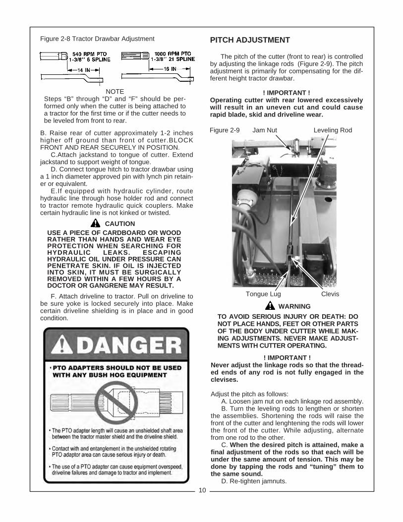
Figure 2-8 Tractor Drawbar Adjustment
B. Raise rear of cutter approximately 1-2 incheshigher off ground than front of cutter.BLOCKFRONT AND REAR SECURELY IN POSITION.
C.Attach jackstand to tongue of cutter. Extendjackstand to support weight of tongue.
D. Connect tongue hitch to tractor drawbar usinga 1 inch diameter approved pin with lynch pin retain-er or equivalent.
E.If equipped with hydraulic cylinder, routehydraulic line through hose holder rod and connectto tractor remote hydraulic quick couplers. Makecertain hydraulic line is not kinked or twisted.
NOTESteps “B” through “D” and “F” should be per-formed only when the cutter is being attached toa tractor for the first time or if the cutter needs tobe leveled from front to rear.
Figure 2-9 Jam Nut Leveling Rod
CAUTIONUSE A PIECE OF CARDBOARD OR WOODRATHER THAN HANDS AND WEAR EYEPROTECTION WHEN SEARCHING FORHYDRAULIC LEAKS. ESCAPINGHYDRAULIC OIL UNDER PRESSURE CANPENETRATE SKIN. IF OIL IS INJECTEDINTO SKIN, IT MUST BE SURGICALLYREMOVED WITHIN A FEW HOURS BY ADOCTOR OR GANGRENE MAY RESULT.F. Attach driveline to tractor. Pull on driveline to
be sure yoke is locked securely into place. Makecertain driveline shielding is in place and in goodcondition.
Tongue Lug Clevis
WARNING
! IMPORTANT !Never adjust the linkage rods so that the thread-ed ends of any rod is not fully engaged in theclevises.
Adjust the pitch as follows:A. Loosen jam nut on each linkage rod assembly.B. Turn the leveling rods to lengthen or shorten
the assemblies. Shortening the rods will raise thefront of the cutter and lenghtening the rods will lowerthe front of the cutter. While adjusting, alternatefrom one rod to the other.
C. When the desired pitch is attained, make afinal adjustment of the rods so that each will beunder the same amount of tension. This may bedone by tapping the rods and “tuning” them tothe same sound.
D. Re-tighten jamnuts.
TO AVOID SERIOUS INJURY OR DEATH: DONOT PLACE HANDS, FEET OR OTHER PARTSOF THE BODY UNDER CUTTER WHILE MAK-ING ADJUSTMENTS. NEVER MAKE ADJUST-MENTS WITH CUTTER OPERATING.
PITCH ADJUSTMENT
The pitch of the cutter (front to rear) is controlledby adjusting the linkage rods (Figure 2-9). The pitchadjustment is primarily for compensating for the dif-ferent height tractor drawbar.
! IMPORTANT !Operating cutter with rear lowered excessivelywill result in an uneven cut and could causerapid blade, skid and driveline wear.

11
SECTION IIIOPERATING INSTRUCTIONS
3-1 GENERAL SAFETY
Only qualified people familiar with this operator’smanual should operate this machine. Operatorshould wear hard hat, safety glasses and safetyshoes. The operator should read, understand andpractice all safety messages shown on the caution,warning and danger decals affixed to the cutter toavoid serious injury or death. Use ROPS (RolloverProtective Structure) and seatbelt equipped tractorsfor mowing operations. Buckle up seat belt to avoidaccidental fall and possible injury from cutter. Beforebeginning operation, clear work area of any objectsthat may be picked up and thrown. Check for ditch-es, stumps, holes or other obstacles that could upsettractor or damage cutter. Always turn off tractorengine, set parking brake, lower cutter to ground andallow blades to come to a complete stop before leav-ing tractor operator’s seat.
3-2 TRANSPORTING
Turn off PTO drive and fully raise cutter before trans-porting. When implement is transported on road orhighway, day or night, use tractor flashing warninglights unless prohibited by law. A slow moving vehi-cle sign (SMV) must be visible from the rear byapproaching vehicles. Do not exceed 15 mph.
3-3 CUTTING HEIGHT ADJUSTMENT
The cutter should be operated at the highest positionwhich will give desired cutting results. This will helpprevent blades from striking ground, reducing bladewear and undue strain on the machine. For bestresults under heavier cutting conditions, always setthe front of cutter approximately 2 inches lower thanthe rear. This tilt decreases horsepower require-ments and increases potential ground speed. Whenfine shredding is desired, adjust cutter deck level orslightly lower in the rear. This will keep the foilageunder cutter until thoroughly shredded. More poweris required for shredding.
Two methods of height adjustment are available - ahydraulic cylinder or a ratchet. Both methods give acutting height of 2 - 12 inches. Stop collars are pro-vided with the hydraulic cylinders. These collars maybe placed around cylinder rod to stop cylinders atdesired cutting height.
When cutting height is adjusted on pull type cutters,the self-leveling linkage will adjust tongue heightautomatically. The front to rear slope of cutter deckcan be changed by adjusting the length of the level-ing rod as described in “Pitch Adjustment”.
3-4 OPERATIONA. Perform BEFORE EACH USE maintenance
listed in paragraph 4-1.
B. Make certain jackstand is stored for work.(Pull units only)
C. Start tractor per tractor operator’s manual. Lowercutter to desired cutting height. On lift models, floatinglink should be positioned as shown in Figure 2-7.
D. With tractor at idle speed, engage PTO drive.Advance throttle to correct operating speed (540or 1000 PTO rpm) for implement.
E. Place tractor in low gear and begin cut-ting. Tractor forward speed should be controlled bygear selection, not engine speed. For maximumcutting efficiency, forward speed should allow cut-ter to maintain a constant maximum blade speed.Always cut up and down the face of slopes, neveracross.
If tractor engine stalls, do not slip tractor clutch toallow engine to regain speed as this will exert unduestrain on the implement drivetrain. When stallingoccurs, disengage tractor PTO drive, move to a cutarea, set throttle to idle, then re-engage PTO drive.Select lower tractor gear if cutter stalls continuously.
DANGERSTAY CLEAR OF ROTATING DRIVELINES.DO NOT OPERATE WITHOUT DRIVELINESHIELDS IN PLACE AND IN GOOD CONDI-TION. FAILURE TO HEED THESE WARNINGSMAY RESULT IN PERSONAL INJURY ORDEATH.
STAND CLEAR OF ROTATING CUTTERBLADES UNTIL ALL MOTION HAS STOPPED.TO AVOID ACCIDENTAL FALL AND POSSI-BLE INJURY FROM CUTTER, IT IS RECOM-MENDED THAT TRACTOR BE EQUIPPEDWITH ROLLOVER PRETECTIVE SYSTEM ANDTHAT A SEAT BELT BE USED FOR ALLOPERATIONS.
ALL ROTARY CUTTERS HAVE THE ABILITYTO DISCHARGE OBJECTS AT HIGH SPEEDSWHICH COULD RESULT IN SERIOUS INJURYTO BYSTANDERS OR PASSERS-BY.
DO NOT OPERATE CUTTER IN VACINITY OFOTHER PERSONS. CEASE MOWING WHEN-EVER ANYONE COMES WITHIN THE OPER-ATING AREA.
KEEP ENCLOSED SIDES, PERMANENTBANDS, BELTING, HIGHWAY CHAINS OROTHER FACTORY APPROVED DISCHARGESHIELDS IN PLACE AND IN GOOD CONDITION.
DANGER
WARNING
12
SECTION IVMAINTENANCE
4-1 MAINTENANCE CHECK LIST
Perform scheduled maintenance as outlined below.Lower implement to ground, turn off tractor, and setparking brake before doing maintenance inspectionsor work. Some checks may require raising machineoff ground and supporting with blocks. All boltsshould be torqued as indicated in torque chartunless otherwise indicated.
BEFORE EACH USE1. Perform BEFORE EACH USE lubrication per
paragraph 4-2.2. Check blades and spindles to be sure that no for
eign objects such as wire or steel strappingbands are wrapped around them.
3. Inspect blades for wear. Replace if necessaryper paragraph 4-3. Always replace both bladeswith two blades equal in weight. Use only gen-uine Bush Hog replacement parts.
4. Check blade bolts for tightness. Tighten to600 ft./lbs.
5. Make certain all shields are in place and in good condition. Repair or replace any missing or dam-aged shields.
6. Inspect wheel(s) for wear, damage or foreignobjects. Repair or replace if necessary.
7. Check tractor tire air pressure. Refer to tractoroperator’s manual.
8. During operation, listen for abnormal soundswhich might indicate loose parts, damaged bear-ings or other damage. Correct any deficiencybefore continuing operation.
AFTER EACH USE1. Clean all debris from machine especially under-
side of deck and affixed safety decals. Replaceany missing or illegible decals.
WARNINGTHE CUTTER CAN FALL FROMHYDRAULIC SYSTEM RELEASE. TOAVOID SERIOUS INJURY OR DEATH,SECURELY SUPPORT CUTTERBEFORE WORKING UNDERNEATH.
2. Inspect cutter for worn or damaged components.Repair or replace before next use. Any replace-ment components installed during repair shallinclude the components current safety decalsspecified by the manufacturer to be affixed tothe component.
3. Store cutter in a dry place.
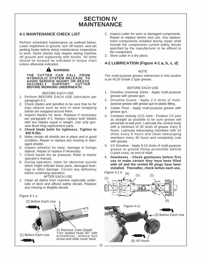
4-2 LUBRICATION (Figure 4-1 a, b, c, d)
NOTEThe multi-purpose grease referenced in this sectionis an NLGI Grade 2 type grease.
BEFORE EACH USE1. Driveline Universal Joints - Apply multi-purpose
grease with grease gun.2. Driveline Guard - Apply 2-3 shots of multi-
purpose grease with grease gun to plastic fitting.3. Caster Pivot - Apply multi-purpose grease with
grease gun.4. Constant Velocity (CV) Joint - Position CV joint
as straight as possible to be sure grease will penetrate to ball joint. Lubricate the central body with a minimum of 30 shots of grease every 8 hours. Lubricate telescoping members with 10shots every 8 hours and clean telescopingmembers every 40 hours and completely coat with grease.
5. CV Driveline - Apply 8-10 shots of multi-purpose grease to grease fitting accessible behindU-joint cross, on end of shaft.
6. Gearboxes - Check gearboxes before firstuse to make certain they have been filled with oil and the vented fill plugs have been installed. Thereafter, check before each use,
Figure 4-1 a
(3) Before Each Use
(6) 40 Hours
Figure 4-1c
Figure 4-1 b
(2) Before Each Use
(1) Before Each UseTo Remove Yoke Shield:Turn slotted head 90° withscrewdriver, remoce turnscrew and slide cover back
(1)(4) (1) (1)
(5)

4-3 BLADE REPLACEMENT
It is not necessary to remove the complete bladeholder assembly to replace the blades. Blade boltsare accessible through a hole in the top of the cutterdeck. Always replace both blades on a spindle.Always use two blades that are equal in weight.Use only genuine Bush Hog replacement parts.
A. Remove nuts and lockwashers from bladebolts. Remove blades and bolts.
B. Inspect blade bolts for wear. Replace if neces-sary.
C. Assemble new blades to blade holder usingblade bolts, lockwashers and nuts. Tighten nuts to600 ft./lbs. Strike blade bolt head with heavyhammer to seat, then retighten.
D. Check to be sure blades swing 360 degreesfreely. If blades will not swing freely, remove,locate problem and repair. Operating cutterwhen blades will not swing freely will causeexcessive vibration, damaging implement.
4-4 GEARBOX REMOVAL
A. (If applicable) Remove cotter pin and lowershaft nut. Wearing heavy gloves, grasp blade holderassembly and pull off shaft. If stuck, align blade boltwith access hole in top of cutter deck and drive offwith hammer and pipe. Care should be taken not todamage threads. (Figure 4-2)
B. Remove cross shaft shields and input shield.C. Remove fasteners retaining center gearbox to deck.D. Rotate center gearbox until cross shaft disen-
gages from gearbox shaft. Remove gearbox fromcutter deck.
E. Remove bolts retaining outboard gearbox to deck.F. Rotate outboard gearbox until cross shaft dis-
engages from gearbox shaft. Remove gearbox fromcutter deck.
WARNINGTHE CUTTER CAN FALL FROM HYDRAULICSYSTEM RELEASE. TO AVOID SERIOUSINJURY OR DEATH, SECURELY SUPPORTCUTTER BEFORE WORKING UNDERNEATH.
Figure 4-2 Cross Shields
Cross Shaft
Blade BoltAccess Hole
Lower Shaft Nut
Blade Bolt
Blade Holder
Input Shield
Outboard Gearbox
(9) 40 Hours
(8) 40 Hours
(6) Before Each Use
Figure 4-1 c
adding EP80W-90 gear oil, if necessary, to bring oil level to check plug on center and outer gearboxes.
20 HOURS7. Driveline (Lift & Swing Hitch) - Disconnect
driveline, pull the two sections apart, apply thin coat of multi-purpose grease to outside of inner (male) section. Reassemble sec-tions and install. Pull each section to be sure driveline and shields are securely connected. Make certain PTO shielding is ingood condition.
NOTE: On jackshaft versions of the pull type thePTO driveline does not telescope. The jackshaftmay be lubricated by aligning holes in theshields to reveal the grease fitting.
40 HOURS8. Wheel Hub Bearings - Apply multi-purpose
grease with grease gun.9. Leveling Rod Clevis - Apply multi-purpose
grease with grease gun.
(7) 20 Hours
13

14
4-5 GEARBOX INSTALLATION
A. Raise cutter and SECURELY SUPPORTWITH BLOCKS.
B. Slide cross shaft as far as possible onto out-board gearbox shaft.
C. Rotate gearbox slightly to allow cross shaft tobe installed. NOTE: Connect cross shaft to gearbox-es insuring that blade pans are timed as shown inFigure 4-3. Incorrect timing will allow blades tohit. Slide cross shaft onto center gearbox shaft untilQ.D. pin snaps into place.
D. Attach gearbox to cutter deck using 5/8” cap-screws. On the outboard gearboxes, the capscrewsshould be inserted from the underside of the deckand up through the gearbox flange. Fasten with 5/8”locknuts.
E. Install blade holder assembly onto gearboxlower shaft. Tighten retaining nut to 450 ft./lbs.Strike blade bar with sledge hammer at the bladebolt area. Retorque shaft nut to 450 ft./lbs. Installcotter pin to retain nut.
F. Install input shield and cross shaft shields.
4-6 SLIP CLUTCH OPERATIONAL CHECK
After the implement has been stored for 30 daysor more, perform the following operational check:
A. Loosen eight nuts retaining clutch springs 1/3turn or until spring can be turned with fingers.
B. With tractor at idle speed, engage tractor PTOdrive for 2-3 seconds. Clutch should slip without turn-ing blades. If clutch does slip, contact your authorizedBush Hog dealer.
C. Retighten nuts to within 1/64” of original posi-tion. See Figure 4-4 for proper spring length.
4-7 SLIP CLUTCH ADJUSTMENT
The slip clutch is factory preset to the correct torquefor protecting implement and tractor. Periodic adjust-ment is recommended; refer to Section 4-6. Shouldadjustment be needed, first check to be sure allspring lengths are the same. Initial spring lengthsshould be 1- 5/16” or 33.5mm. If necessary, adjustnut on any spring that is unequal. Adjust all eightspring retaining nuts 1/3 turn increments or consultyour Bush Hog dealer. Adjust only to provide siffi-cient torque to prevent slippage under normalconditions. Occasional slippage is normal for drive-train protection. If satifactory results cannot beobtained, consult your Bush Hog dealer.
Figure 4-4Spring Length 1-5/16”
(33.5mm)
OVERTIGHTENING SPRING NUTS MAYCAUSE DAMAGE TO IMPLEMENT AND/ORTRACTOR DUE TO INCORRECT SLIP CLUTCHTORQUE SETTING. ALWAYS FOLLOW THEPROPER ADJUSTMENT PROCEDURE.
Figure 4-3 Blade Pan Timing As Viewed From Bottom Of Cutter
WARNING

15
4-8 TROUBLESHOOTINGTroubleshooting procedures are listed in Table 4-2 below. If the problem cannot be solved or replacementparts are necessary, contact your authorized Bush Hog dealer. Please have ready your machine name, modelnumber, serial number, purchase date and exact cause or description of problem.
Table 4-2 Troubleshooting
PROBLEM PROBABLE CAUSE REMEDYUneven Cut Cutter not level side to side. See Section II.
Worn or bent blades. Replace blades.
Stripping or Windrowing Possible build-up of material Clean cutter.under cutter.Cutter not level. See Section II.Worn blades. Replace blades.
Noisy Cutter Loose components. Check all bolts for tightness.Low oil in gearbox. Check oil per paragraph 4-2.Blades out of time. See paragraph 4-5.
Rapid Blade Wear Blade contacting ground. Adjust cutting height to eliminate(cutting edge) ground contact.
Rapid Wear of Blade Hole Cutter not being operated at rated Set tractor throttle for properand Blade Bolt Shoulder PTO speed. PTO speed.
Poor Shredding Job Incorrect deck tilt. See paragraph 3-2.Excessive ground speed. Use lower gear.Worn blades. Replace blades.
SECTION VDEALER ASSEMBLY
1. Wear personal protective equipment such as, butnot limited to, protection for eyes, ears, feet,hands, lungs and head when assembling the equipment. Do not wear loose clothing or jewelry that may catch on equipment moving parts.
2. Do not lift heavy parts or assemblies. Use crane,jack, tackle, fork trucks, or other mechanicaldevices.
3. Select an area for assembly that is clean andfree of any debris which might cause personsworking on the assembly to trip.
4. Arrange parts to be assembled neatly in the workarea and have tools or other mechanical assist-ing devices in easy reach.
5. Inspect all parts and assemblies thoroughly and remove any sharp edges, grease, oil, or dirtwhich might cause pieces to slip when handling.
THE FOLLOWING SAFETY PRECAUTIONSSHOULD BE THOROUGHLY UNDERSTOODBEFORE ATTEMPTING MACHINE ASSEMBLY.
6. Preview the assembly instructions in your opera-tor’s manual before proceeding further.
7. If the assembly instructions call for parts orassemblies to be blocked up, use only blocking material that is in good condition and is capable of handling the weight of the assembly to beblocked. Also insure that the blocking material ison a clean, dry surface.
8. Never put hands or any other part of body under blocked up assemblies if at all possible.
9. Always wear goggles or safety glasses whenhammering, grinding or drilling metal parts.
10. If the assembly calls for welding or cutting, be sure that there are no flammable materials closeat hand and that bystnders have taken neces-sary precautions.
AFTER COMPLETING ANY ASSEMBLY STEP,THOROUGHLY READ THE NEXT STEP IN THEASSEMBLY INSTRUCTIONS BEFORE PROCEED-ING WITH THAT STEP.
11. After completing assembly, thoroughly inspect the machine to be sure that all nuts, bolts,
CAUTON

16
hydraulic fittings or any other fastened assem-blies have been thoroughly tightened.
12. After completing assembly, be sure that all safetylocking devices or guards are in place.
13. Before operating the machine, thoroughly readthe operation section of this manual.
14. Before operating, read the maintenance sectionof this manual to be sure that any parts requiringlubrication such as gearboxes are full to avoidany possible damage.
BEFORE OPERATING THE EQUIPMENT, IF YOUHAVE ANY QUESTIONS REGARDING THE PROP-ER ASSEMBLY OR OPERATION, CONTACT YOURAUTHORIZED BUSH HOG REPRESENTATIVE.
5-1 LIFT MODEL ASSEMBLY
A. Slide clutch end of driveline onto centergearbox and tighten hex nut provided to 30 ft. lbs.
B. Attach mast assembly to deck assembly using3/4 x 2” bolts and flanged locknuts. Thread locknutuntil it touches mast, but do not tighten, allowing mastto pivot. (Figure 5-1)
C. Fasten right and left mast supports to deckassembly using axle mounting bolts and 1/2” longbushings.
D. Secure mast supports to flex link using two 3/4x 2-1/2” bolts, 11/16” long bushings, lockwashers andnuts.
E. Fasten caster mount weldments to axle usingfour 3/4 x 5-1/2” bolts, plates, lockwashers and nutseach.
F. Install wheel assemblies onto caster hubs.Fasten with collar and roll pin.
G. Pin ratchet or hydraulic cylinder to axle anddeck assembly. If hydraulic cylinder is used, plumbas shown in Figure 5-2.
H. Install lift pins and adapter bushings securinglift pins with linch pin retainers.
I. Remove temporary fill plugs and fill gearbox-es to oil level check plug with EP80W-90 gear oil.Install vented fill plugs included in Operator’sManual package.
J. Prior to delivery to customer, perform slip clutchoperational check as described in pargraph 4-6.
Figure 5-2 Cylinder PlumbingHose Adaptor
Adaptor
Hydraulic Cylinder
Breather Plug
9/16” JIC to 3/4” SAEor 9/16” JIC to 1/2” NPT
9/16” JIC to 3/4”SAE
Figure 5-3 Front Discharge Shield
Front Chain Assembly
Figure 5-1 Lift Unit Assembly Flex Link
Mast Support
Ratchet
Caster Assembly
Wheel Assembly
Lift Pin
Rear Discharge ShieldInput Shield
Driveline
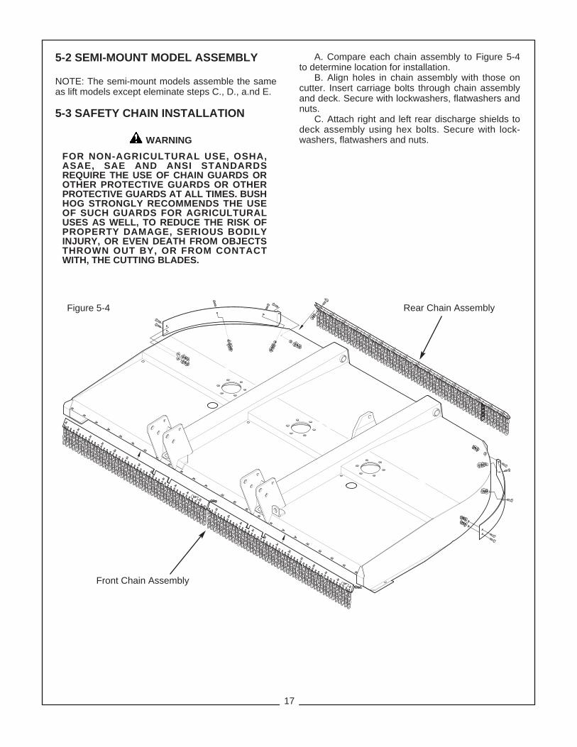
5-2 SEMI-MOUNT MODEL ASSEMBLY
NOTE: The semi-mount models assemble the sameas lift models except eleminate steps C., D., a.nd E.
5-3 SAFETY CHAIN INSTALLATION
FOR NON-AGRICULTURAL USE, OSHA,ASAE, SAE AND ANSI STANDARDSREQUIRE THE USE OF CHAIN GUARDS OROTHER PROTECTIVE GUARDS OR OTHERPROTECTIVE GUARDS AT ALL TIMES. BUSHHOG STRONGLY RECOMMENDS THE USEOF SUCH GUARDS FOR AGRICULTURALUSES AS WELL, TO REDUCE THE RISK OFPROPERTY DAMAGE, SERIOUS BODILYINJURY, OR EVEN DEATH FROM OBJECTSTHROWN OUT BY, OR FROM CONTACTWITH, THE CUTTING BLADES.
A. Compare each chain assembly to Figure 5-4to determine location for installation.
B. Align holes in chain assembly with those oncutter. Insert carriage bolts through chain assemblyand deck. Secure with lockwashers, flatwashers andnuts.
C. Attach right and left rear discharge shields todeck assembly using hex bolts. Secure with lock-washers, flatwashers and nuts.
Rear Chain Assembly
Front Chain Assembly
Figure 5-4
WARNING
17

18
Figure 5-7Safety Tow Chain
5-5 SAFETY TOW CHAIN
A. Securely attach tow chain to cutter by loopinghook end of chain around one side of tongue andback through large l ink on opposite end ofchain.(Figure 5-7)
B. Before use, attach loose end of chain to tow-ing vehicle attaching point such as drawbar orbumper, etc. Fasten chain back to itself with hooklatch.
5-3 REAR BAND INSTALLATION
A. Attach center rear discaharge shield to cutterdeck and outer shields using hex bolts, lockwashers,flatwashers and nuts.
B. Attach right and left rear discharge shields todeck assembly using hex bolts. Secure with lock-washers, flatwashers and nuts.
C. Tighten all nuts.
5-4 FRONT BELTING
Attach front belting to deck assembly and securewith carriage bolts, flatwashers, lockwashers andnuts.
Front Belting
Rear Band
Jackshaft
Pillow Block Assembly
Figure 5-5
Figure 5-6
Figure 5-8Pull Model With Pillow BlockAnd Jackshaft
Tongue
NOTE; On this model thejackshaft is a telescopingmember and the input shaftfrom the tractor PTO shaft isa fixed length.

19
5-6 PULL MODEL ASSEMBLY
A. Attach tongue to deck assembly using two 1”x 8” bolts, bushings and locknuts. (Figure 5-8, 5-9)
PULL MODEL DRIVELINES
On pull model there is a selection of two types ofinput drivelines. On unit equipped with:
B. 1 Constant Velocity Driveline
Slide clutch end onto center gearbox input shaftand tighten hex nut provided to 30 ft. lbs.
B. 2 Cardan / Jackshaft Driveline (Figure 5-8)
1. Slide pillow block onto jackshaft, with lock col-lar toward the cutter, until it is against shoulder. Slidelock collar up to bearing and turn in the direction ofshaft rotation until it slips over the inner ring exten-sion. Turn collar quickly in the direction of shaft rota-tion (approx. 1/4 turn) to tighten. (Figure 5-10)
2. Slide clutch end of driveline onto center gearboxinput shaft and tighten hex nut provided to 30 ft. lbs.
3. Assemble jackshaft mount assembly betweentongue halves and secure with hex bolts, flatwashers,lockwashers and nuts.
4. Before setting lock collar on bearing, assem-ble the driveline to the jackshaft by first assem-bling the tubing spacer onto the jackshaft end.Attach driveline to jackshaft insuring the tubingspacer is in place and tighten hex nut provided to30 ft. lbs.
5. Place punch in blind hole in collar. Strike punchsharply with hammer in the direction of shaft rotation tolock collar against inner ring extension.
6. Tighten setscrew to 20 ft. lbs.7. Attach bearing shield, beveled end forward, to
top of pillow block bearing using 3/8’ x 3/4” bolts andlockwashers.
C. Attach hose holder rod to tongue using 1/2 x2” bolt, flatwasher and nut.
D. Fasten axle arm mount weldments to axleusing four 3/4 x 5-1/2” bolts, plates, lockwashersand nuts each.
E. Mount wheels on hubs securing with lug nuts.When using laminated tires, the flat side of thelug nut should be against the rim. When usingautomotive rims, the tapered side of the lugshould be against the rim.
F. Pin ratchet or hydraulic cylinder to axle anddeck assembly. If hydraulic cylinder is used, plumbas shown in Figure 5-2 and route hose through hoseholder rod.
G. Pin jackstand to tongue.H. Pin leveling rods to axle lug and tongue
lugs.The clevis with the elongated hole must pin tothe tongue lug.
I. Remove temporary fill plugs and fill gear-boxes to oil level check plug with EP89W-90gear oil. Install vented fill plugs included inOperator’s Manual package.
J. Prior to delivery to customer, perform slipclutch operational check as described in para-graph 4-6.
Figure 5-9 Pull Model
Tongue Assembly
Leveling Rod Front Chain Guards
Driveline
Pillow BlockBearing Shield
Hose Holder Rod
Input Shield
Hydraulic CylinderAxle Arm Mount
Wheel Assembly
Left RearD i s c ha r g eShield
Vented Fill PlugJackstand
Light Kit
Pillow Block BearingJackshaft
Inner RingExtension
Spacer Tube
Lock Collar
Punch
Lock Collar
Lug Nut
Flat SideTapered Side
Figure 5-10

SAFETY DECALSTo promote safe operation, Bush Hog supplies safety decals on all products manufactured. Because damagecan occur to safety decals either through shipment, use or reconditioning, Bush Hog will, upon request, providesafety decals for any of our products in the field at no charge. Contact your authorized Bush Hog dealer formore information.
20
50029417
7878678608
50029418
50029419

TORQUE SPECIFICATIONSProper toque for American fasteners used on Bush Hog equipment.
Recommended Torque in Foot Pounds (Newton Meters).*
Proper torque for metric fasteners used on Bush Hog equipment.Recommended torque in foot pounds (newton Meters).*
WRENCH BOLTSIZE DIA. ASTM ASTM ASTM ASTM
(mm) “A” (mm) “B” 4.6 8.8 9.8 10.98 5 1.8 (2.4) 5.1 (6.9) 6.5 (8.8)
10 6 3 (4) 8.7 (12) 11.1 (15)
13 8 7.3 (10) 21.1 (29) 27 (37)
16 10 14.5 (20) 42 (57) 53 (72)
18 12 25 (34) 74 (100) 73 (99) 93 (126)
21 14 40 (54) 118 (160) 116 (157) 148 (201)
24 16 62 (84) 167 (226) 181 (245) 230 (312)
30 20 122 (165) 325 (440) 449 (608)
33 22 443 (600) 611 (828)
36 24 211 (286) 563 (763) 778 (1054)
41 27 821 (1112) 1138 (1542)
46 30 418 (566) 1119 (1516) 1547 (2096)
*Use 75% of the specified torque value for platedfasteners. Use 85% of the specified torque valuesfor lubricated fasteners.
Numbers appearing on bolt headsindicate ASTM class.
METRIC
AMERICANBolt Head Markings
WrenchSize “A”
Bolt
Diameter “B”
SAE Grade 8(6 Dashes)
SAE Grade 2(No Dashes)
SAE Grade 5(3 Dashes)
WrenchSize “A” 8.8
Bolt
Diameter “B”
21
BOLT DIAMETERWRENCH (IN.) “B” AND SAE SAE SAE
SIZE (IN.) “A” THREAD SIZE GRADE 2 GRADE 5 GRADE 8
7/16 1/4 - 2O UNC 6 (7) 8 (11) 12 (16)
7/16 1/4 - 28 UNF 6 (8) 10 (13) 14 (18)
1/2 5/16 - 18 UNC 11 (15) 17 (23) 25 (33)
1/2 5/16 - 24 UNF 13 (17) 19 (26) 27 (37)
9/16 3/8 - 16 UNC 20 (27) 31 (42) 44 (60)
9/16 3/8 - 24 UNF 23 (31) 35 (47) 49 (66)
5/8 7/16 - 14 UNC 32 (43) 49 (66) 70 (95)
5/8 7/16 - 20 UNF 36 (49) 55 (75) 78 (106)
3/4 1/2 - 13 UNC 49 (66) 76 (103) 106 (144)
3/4 1/2 - 20 UNF 55 (75) 85 (115) 120 (163)
7/8 9/16 - 12 UNC 70 (95) 109 (148) 153 (207)
7/8 9/16 - 18 UNF 79 (107) 122 (165) 172 (233)
15/16 5/8 - 11 UNC 97 (131) 150 (203) 212 (287)
15/16 5/8 - 18 UNF 110 (149) 170 (230) 240 (325)
1-1/8 3/4 - 10 UNC 144 (195) 266 (360) 376 (509)
1-1/8 3/4 - 16 UNF 192 (260) 297 (402) 420 (569)
1-5/16 7/8 - 9 UNC 166 (225) 430 (583) 606 (821)
1-5/16 7/8 - 14 UNF 184 (249) 474 (642) 668 (905)
1-1/2 1 - 8 UNC 250 (339) 644 (873) 909 (1232)
1-1/2 1 - 12 UNF 274 (371) 705 (955) 995 (1348)
1-1/2 1 - 14 UNF 280 (379) 721 (977) 1019 (1381)
1-11/16 1-1/8 - 7 UNC 354 (480) 795 (1077) 1288(1745)
1-11/16 1-1/8 - 12 UNF 397 (538) 890 (1206) 1444 (1957)
1-7/8 1-1/4 - 7 UNC 500 (678) 1120 (1518) 1817 (2462)
1-7/8 1-1/4 - 12 UNF 553 (749) 1241 (1682) 2013 (2728)
2-1/16 1-3/8 - 6 UNC 655 (887) 1470 (1992) 2382 (3228)
2-1/16 1-3/8 - 12 UNF 746 (1011) 1672 (2266) 2712 (3675)
2-1/4 1-1/2 - 6 UNC 870 (1179) 1950 (2642) 3161 (4283)
2-1/4 1-1/2 - 12 UNF 979 (1327) 2194 (2973) 3557 (4820)

2501 Griffin Ave. ll Selma, AL 36703Telephone (334) 874-2700 ll www.bushhog.com