2010 Dodge Journey User's Manual - Vehicles · PDF fileWELCOMEFROMCHRYSLERGROUPLLC...
84
2010
Transcript of 2010 Dodge Journey User's Manual - Vehicles · PDF fileWELCOMEFROMCHRYSLERGROUPLLC...
2010

IMPORTANT: This User Guide is intended to familiarize you with the important features of your vehicle. The DVD enclosed contains your Owner’s Manual, Navigation Radio or Multimedia Radio Manual, Warranty Booklets, Tire Warranty and 24-Hour Towing Assistance (new vehicles purchased in the U.S.) or Roadside Assistance (new vehicles purchased in Canada) in electronic format. We hope you find it useful. If you are the first registered owner of your vehicle, you may obtain a printed copy of the Owner’s Manual, Navigation Radio or Multimedia Radio Manual or Warranty Booklet by calling 1-800-992-1997 (U.S.) or 1-800-387-1143 (Canada) or by contacting your dealer. Replacement manuals may be purchased by visiting www.techauthority.com. Copyright © 2009 Chrysler Group LLC.

INTRODUCTION/WELCOMEWELCOME FROMCHRYSLER GROUP LLC . . . . . . . . . . . 2
CONTROLS AT A GLANCEDRIVER COCKPIT . . . . . . . . . . . . . . 4INSTRUMENT CLUSTER . . . . . . . . . . 6
GETTING STARTEDKEY FOB . . . . . . . . . . . . . . . . . . . 8THEFT ALARM . . . . . . . . . . . . . . . . 9SEAT BELT . . . . . . . . . . . . . . . . . 9FRONT SEATS . . . . . . . . . . . . . . . . 9REAR SEATS . . . . . . . . . . . . . . . . 13TILT/TELESCOPING STEERINGCOLUMN . . . . . . . . . . . . . . . . . .16PROGRAMMABLE FEATURES . . . . . . .16
OPERATING YOUR VEHICLETURN SIGNAL/LIGHTS LEVER . . . . . . .18WIPER/WASHER LEVER . . . . . . . . . .19SPEED CONTROL LEVER . . . . . . . . . 20MANUAL CLIMATE CONTROLS . . . . . . . 21MANUAL THREE ZONE CLIMATECONTROL . . . . . . . . . . . . . . . . . . 21TWO AND THREE ZONE AUTOMATICTEMPERATURE CONTROL (ATC) . . . . . .23PARKVIEW® REAR BACK-UP CAMERA . . 24POWER SUNROOF . . . . . . . . . . . . .25WIND BUFFETING . . . . . . . . . . . . . 26
ELECTRONICSNON-TOUCH-SCREEN RADIOS . . . . . . .27AM/FM/CD NAVIGATION RADIO . . . . . 30AM/FM/CD MULTIMEDIA TOUCH-SCREENRADIO . . . . . . . . . . . . . . . . . . . .34REMOTE AUDIO CONTROLS . . . . . . . 36VIDEO ENTERTAINMENT SYSTEM(VES)™ . . . . . . . . . . . . . . . . . . 36UNIVERSAL CONSUMER INTERFACE . . . 38ELECTRONIC VEHICLE INFORMATIONCENTER (EVIC) . . . . . . . . . . . . . . 39UNIVERSAL GARAGE DOOR OPENER . . 39POWER INVERTER . . . . . . . . . . . . . 41POWER OUTLET . . . . . . . . . . . . . 42
uconnect™ phone . . . . . . . . . . . . 42VOICE RECOGNITION . . . . . . . . . . . .44
UTILITYTRAILER TOWING WEIGHTS (MAXIMUMTRAILER WEIGHT RATINGS) . . . . . . . .45RECREATIONAL TOWING (BEHINDMOTORHOME, ETC.) . . . . . . . . . . . 46BRAKE/TRANSAXLE INTERLOCK MANUALOVERRIDE . . . . . . . . . . . . . . . . 46
WHAT TO DO IN EMERGENCIES24 HOUR TOWING ASSISTANCE . . . . . .47INSTRUMENT CLUSTER WARNINGLIGHTS . . . . . . . . . . . . . . . . . . .47IF YOUR ENGINE OVERHEATS . . . . . . .50JACKING AND TIRE CHANGING . . . . . . . 51JUMP-STARTING . . . . . . . . . . . . . .55TOWING A DISABLED VEHICLE . . . . . . .58FREEING A STUCK VEHICLE . . . . . . . .59EVENT DATA RECORDER (EDR) . . . . . 60
MAINTAINING YOUR VEHICLEOPENING THE HOOD . . . . . . . . . . . .61ENGINE COMPARTMENT . . . . . . . . . 62FLUIDS AND CAPACITIES . . . . . . . . . 64MAINTENANCE CHART . . . . . . . . . . 66FUSES . . . . . . . . . . . . . . . . . . . 68TIRE PRESSURES . . . . . . . . . . . . . . 71WHEEL AND WHEEL TRIM CARE . . . . . .72EXTERIOR BULBS . . . . . . . . . . . . . .72
CONSUMER ASSISTANCECHRYSLER GROUP LLC CUSTOMERCENTER . . . . . . . . . . . . . . . . . . .73CHRYSLER CANADA INC. CUSTOMERCENTER . . . . . . . . . . . . . . . . . . .73ASSISTANCE FOR THE HEARINGIMPAIRED . . . . . . . . . . . . . . . . . .73PUBLICATIONS ORDERING . . . . . . . . .73REPORTING SAFETY DEFECTS IN THE50 UNITED STATES ANDWASHINGTON, D.C. . . . . . . . . . . . .74TIRE WARRANTY . . . . . . . . . . . . . .74
MOPAR ACCESSORIESMOPAR® ACCESSORIES . . . . . . . . . .77
TABLE OF CONTENTS

WELCOME FROM CHRYSLER GROUP LLCCongratulations on selecting your new Chrysler Group LLC vehicle. Be assured that itrepresents precision workmanship, distinctive styling, and high quality - all essentialsthat are traditional to our vehicles.
IMPORTANT: This User Guide is intended to familiarize you with the important features ofyour vehicle. The DVD enclosed contains your Owner’s Manual, Warranty Booklets, TireWarranty, and 24 Hour Towing Assistance (new vehicles purchased in the U.S.) orRoadside Assistance (new vehicles purchased in Canada) in electronic format. We hopeyou find it useful. Retail customers may obtain a printed copy of any of these booklets,call 1-800-890-4038 (U.S.) or 1-800-387-1143 (Canada) or ask your dealer.
For complete owner information, refer to the DVD in the owner’s kit provided at the timeof new vehicle purchase. For your convenience, the information contained on the DVDmay also be printed and saved for future reference.
Not all features shown in this guide may apply to your vehicle.
Chrysler Group LLC is committed to protecting our environment and natural resources. Byconverting from paper to electronic delivery for the majority of the user information foryour vehicle, together we greatly reduce the demand for tree-based products and lessenthe stress on our environment.
Vehicles Sold In CanadaWith respect to any Vehicles Sold in Canada, the name Chrysler Group LLC shall bedeemed to be deleted and the name Chrysler Canada Inc. used in substitution therefore.
Driving And AlcoholDrunken driving is one of the most frequent causes of accidents.
Your driving ability can be seriously impaired with blood alcohol levels far below thelegal minimum. If you are drinking, don’t drive. Ride with a designated non-drinkingdriver, call a cab, a friend, or use public transportation.
WARNING!Driving after drinking can lead to an accident. Your perceptions are less sharp, yourreflexes are slower, and your judgment is impaired when you have been drinking.Never drink and then drive.
This guide illustrates and describes the operation of features and equipment that areeither standard or optional on this vehicle. This guide may also include a description offeatures and equipment that are no longer available or were not ordered on this vehicle.Please disregard any features and equipment described in this guide that are notavailable on this vehicle. Chrysler Group LLC reserves the right to make changes indesign and specifications and/or make additions to or improvements to its productswithout imposing any obligation upon itself to install them on products previouslymanufactured.
INTRODUCTION/WELCOME
2
CAUTION!Never park your vehicle over dry grass or other combustible materials. The heat fromyour vehicle exhaust system could cause a fire.
CHRYSLER, DODGE, JEEP, ATF+4, MOPAR and uconnect are registered trademarks ofChrysler Group LLC.COPYRIGHT ©2009 CHRYSLER GROUP LLC
3
INTRODUCTION/WELCOME

DRIVER COCKPIT
4
CONTROLS AT A GLANCE
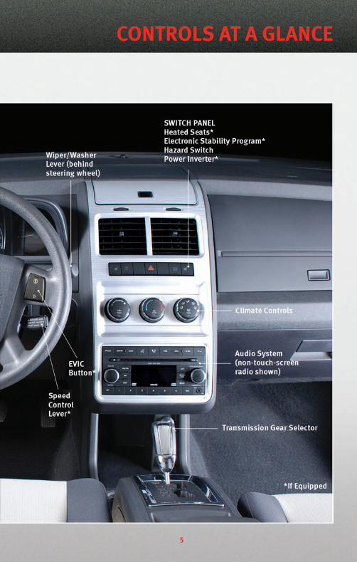
5
CONTROLS AT A GLANCE
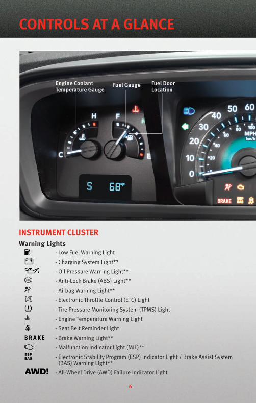
INSTRUMENT CLUSTERWarning Lights
- Low Fuel Warning Light
- Charging System Light**
- Oil Pressure Warning Light**
- Anti-Lock Brake (ABS) Light**
- Airbag Warning Light**
- Electronic Throttle Control (ETC) Light
- Tire Pressure Monitoring System (TPMS) Light
- Engine Temperature Warning Light
- Seat Belt Reminder Light
BRAKE - Brake Warning Light**
- Malfunction Indicator Light (MIL)**
- Electronic Stability Program (ESP) Indicator Light / Brake Assist System(BAS) Warning Light**
- All-Wheel Drive (AWD) Failure Indicator Light
6
CONTROLS AT A GLANCE
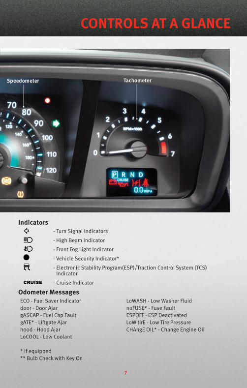
Indicators- Turn Signal Indicators
- High Beam Indicator
- Front Fog Light Indicator
- Vehicle Security Indicator*
- Electronic Stability Program(ESP)/Traction Control System (TCS)Indicator
- Cruise Indicator
Odometer MessagesECO - Fuel Saver Indicator LoWASH - Low Washer Fluiddoor - Door Ajar noFUSE* - Fuse FaultgASCAP - Fuel Cap Fault ESPOFF - ESP DeactivatedgATE* - Liftgate Ajar LoW tirE - Low Tire Pressurehood - Hood Ajar CHAngE OIL* - Change Engine OilLoCOOL - Low Coolant
* If equipped** Bulb Check with Key On
7
CONTROLS AT A GLANCE
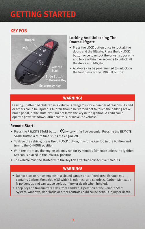
KEY FOBLocking And Unlocking TheDoors/Liftgate• Press the LOCK button once to lock all the
doors and the liftgate. Press the UNLOCKbutton once to unlock the driver’s door onlyand twice within five seconds to unlock allthe doors and liftgate.
• All doors can be programmed to unlock onthe first press of the UNLOCK button.
WARNING!Leaving unattended children in a vehicle is dangerous for a number of reasons. A childor others could be injured. Children should be warned not to touch the parking brake,brake pedal, or the shift lever. Do not leave the key in the ignition. A child couldoperate power windows, other controls, or move the vehicle.
Remote Start• Press the REMOTE START button x2 twice within five seconds. Pressing the REMOTE
START button a third time shuts the engine off.
• To drive the vehicle, press the UNLOCK button, insert the Key Fob in the ignition andturn to the ON/RUN position.
• With remote start, the engine will only run for 15 minutes (timeout) unless the ignitionKey Fob is placed in the ON/RUN position.
• The vehicle must be started with the Key Fob after two consecutive timeouts.
WARNING!• Do not start or run an engine in a closed garage or confined area. Exhaust gas
contains Carbon Monoxide (CO) which is odorless and colorless. Carbon Monoxideis poisonous and can cause serious injury or death when inhaled.
• Keep Key Fob transmitters away from children. Operation of the Remote StartSystem, windows, door locks or other controls could cause serious injury or death.
GETTING STARTED
8

Panic Alarm• Press the PANIC button once to turn the panic alarm on.
• Wait approximately three seconds and press the button a second time to turn thepanic alarm off.
Express Window Feature• To remotely lower both front door windows at the same time, press and release the
UNLOCK button and then immediately press and hold the UNLOCK button until thewindows lower to the level desired or until they lower completely.
Emergency Key• Should the battery in the vehicle or the Key Fob transmitter go dead, there is an
emergency key located in the Key Fob. To remove the emergency key, slide the buttonat the top of the Key Fob sideways with your thumb and then pull the key out with yourother hand.
THEFT ALARMTo Arm• Press the Key Fob LOCK button or the power door lock switch while the door is open.
To Disarm• Press the Key Fob UNLOCK button or turn the ignition to the ON position.
SEAT BELT• Be sure everyone in your vehicle is in a seat using a seat belt properly.
WARNING!In a collision, you and your passengers can suffer much greater injuries if you are notproperly buckled up. You can strike the interior of your vehicle or other passengers, oryou can be thrown out of the vehicle. Always be sure you and others in your vehicleare buckled up properly.
FRONT SEATS
WARNING!Adjusting a seat while the vehicle is moving is dangerous. The sudden movement ofthe seat could cause you to lose control. The seat belt might not be properly adjustedand you could be injured. Only adjust a seat while the vehicle is parked.
9
GETTING STARTED

Manual Seat Adjustment
Forward/Rearward• Lift up on the adjusting bar located at the
front of the seat near the floor and releaseat the desired position.
Lumbar Support/Recliner• The lumbar adjust lever is on the outboard
side of the seatback. Rotate the lumbarlever downward to increase the lumbarsupport or upward to decrease the lumbarsupport as desired.
• Lift the recliner lever located on theoutboard side of the seat, lean back andrelease at the desired position.
WARNING!Do not ride with the seatback reclined so that the seat belt is no longer resting againstyour chest. In a collision, you could slide under the seat belt and be seriously or evenfatally injured. Use the recliner only when the vehicle is parked.
GETTING STARTED
10
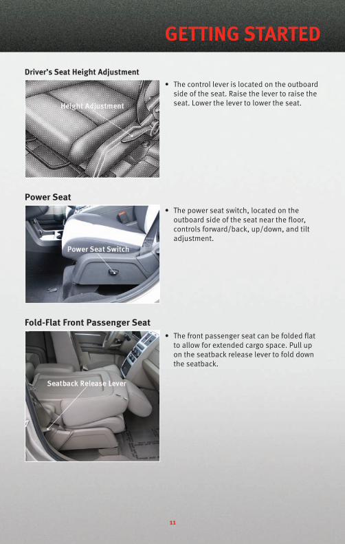
Driver’s Seat Height Adjustment• The control lever is located on the outboard
side of the seat. Raise the lever to raise theseat. Lower the lever to lower the seat.
Power Seat• The power seat switch, located on the
outboard side of the seat near the floor,controls forward/back, up/down, and tiltadjustment.
Fold-Flat Front Passenger Seat• The front passenger seat can be folded flat
to allow for extended cargo space. Pull upon the seatback release lever to fold downthe seatback.
11
GETTING STARTED

Flip 'n Stow™ Front Passenger Seat Storage• The seat latch release-loop is located in the center of the seat cushion between the
seat cushion and the seatback. Pull the loop upward to release the latch and thenforward to open the seat to the detent position.
NOTE: Make sure that objects inside the bin do not interfere with the latch beforeclosing the seat. Push the seat cushion downward after closing it to make sure it latchesto the base.
WARNING!Be certain that the seat cushion is locked securely into position before using the seat.Otherwise, the seat will not provide the proper stability for passengers. An improperlylatched seat cushion could cause serious injury.
Heated Seats• The controls for front heated seats are
located in the switch bank in the center ofthe instrument panel.
• Press the switch once to select High-levelheating. Press the switch a second time toselect Low-level heating. Press the switch athird time to shut the heating elements Off.
WARNING!• Persons who are unable to feel pain to the skin because of advanced age, chronic
illness, diabetes, spinal cord injury, medication, alcohol use, exhaustion or otherphysical condition must exercise care when using the seat heater. It may causeburns even at low temperatures, especially if used for long periods of time.
• Do not place anything on the seat that insulates against heat, such as a blanket orcushion. This may cause the seat heater to overheat. Sitting in a seat that has beenoverheated could cause serious burns due to the increased surface temperature ofthe seat.
CAUTION!Repeated overheating of the seat could damage the heating element and/or degradethe material of the seat.
GETTING STARTED
12
REAR SEATS60/40 Split Second-Row Passenger Seats
To Fold The Seat• Locate the seatback release lever on the lower outboard side of the seat.
• Place one hand on the seatback and apply a gentle pressure.
• Lift the seatback release lever with the other hand, allowing the seatback to moveforward slightly, and then release the lever.
• Gently guide the seatback into the folded position.
To Unfold The Seat• Raise the seatback and lock it in place.
WARNING!Be certain that the seatback is locked securely into position. Otherwise, the seat willnot provide the proper stability for child seats and/or passengers. An improperlylatched seat could cause serious injury.
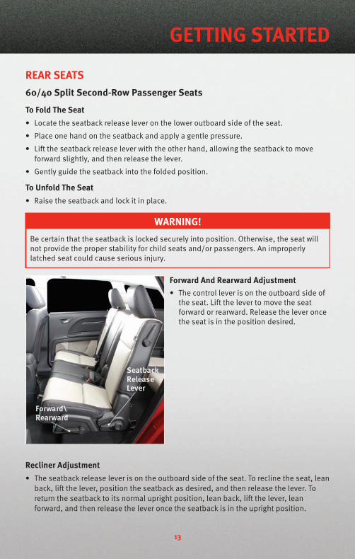
Forward And Rearward Adjustment• The control lever is on the outboard side of
the seat. Lift the lever to move the seatforward or rearward. Release the lever oncethe seat is in the position desired.
Recliner Adjustment• The seatback release lever is on the outboard side of the seat. To recline the seat, lean
back, lift the lever, position the seatback as desired, and then release the lever. Toreturn the seatback to its normal upright position, lean back, lift the lever, leanforward, and then release the lever once the seatback is in the upright position.
13
GETTING STARTED

Stadium Tip ’n Slide™ (Easy Entry/Exit Seat) — Seven Passenger ModelsTo Move The Second-Row Passenger SeatForward
NOTE: Raise the 20% seatback/armrestbefore moving the 60% seat to allow for fullseat travel.
• To allow passengers to easily enter or exitthe third-row passenger seats move the Tip’n Slide™ control lever on the upperoutboard side of the seatback forward, andin one fluid motion, the seat cushion flipsupward and the seat moves forward on itstracks.
To Unfold And Move The Second-Row Passenger Seat Rearward
• Move the seatback rearward until it locks in place and then continue sliding the seatrearward on its tracks until it locks in place.
• Push the seat cushion downward to lock it in place.
• Adjust the seat track position as desired.
WARNING!• Do not drive the vehicle with the seat in this position, as it is only intended for
entering and exiting the third row seats. Failure to follow this warning may result inpersonal injury.
• Be certain that the seatback and seat are locked securely into position. Otherwise,the seat will not provide the proper stability for child seats and/or passengers. Animproperly latched seat could cause serious injury.
GETTING STARTED
14
50/50 Split Third-Row Passenger Seats With Fold-Flat Feature
To Fold The Seat• With the second-row passenger seat fully
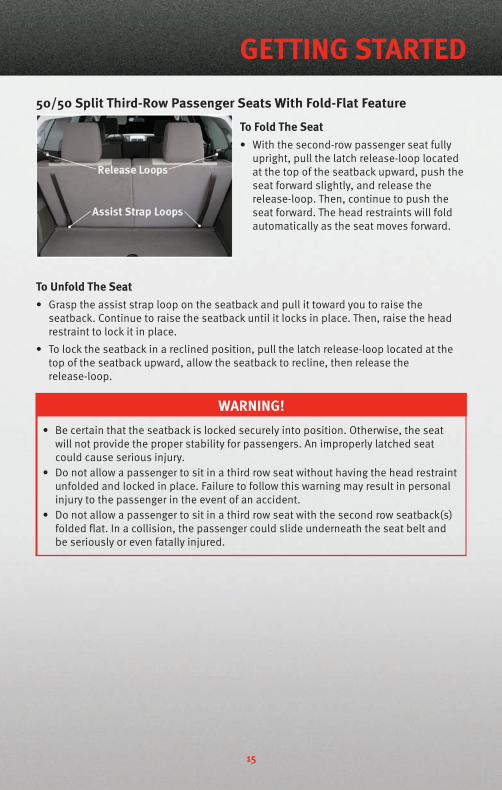
upright, pull the latch release-loop locatedat the top of the seatback upward, push theseat forward slightly, and release therelease-loop. Then, continue to push theseat forward. The head restraints will foldautomatically as the seat moves forward.
To Unfold The Seat• Grasp the assist strap loop on the seatback and pull it toward you to raise the
seatback. Continue to raise the seatback until it locks in place. Then, raise the headrestraint to lock it in place.
• To lock the seatback in a reclined position, pull the latch release-loop located at thetop of the seatback upward, allow the seatback to recline, then release therelease-loop.
WARNING!• Be certain that the seatback is locked securely into position. Otherwise, the seat
will not provide the proper stability for passengers. An improperly latched seatcould cause serious injury.
• Do not allow a passenger to sit in a third row seat without having the head restraintunfolded and locked in place. Failure to follow this warning may result in personalinjury to the passenger in the event of an accident.
• Do not allow a passenger to sit in a third row seat with the second row seatback(s)folded flat. In a collision, the passenger could slide underneath the seat belt andbe seriously or even fatally injured.
15
GETTING STARTED
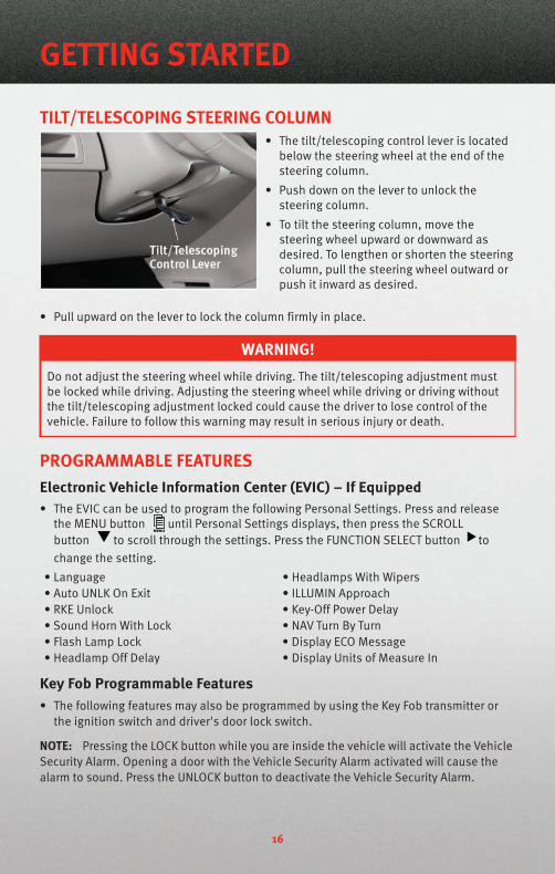
TILT/TELESCOPING STEERING COLUMN• The tilt/telescoping control lever is located
below the steering wheel at the end of thesteering column.
• Push down on the lever to unlock thesteering column.
• To tilt the steering column, move thesteering wheel upward or downward asdesired. To lengthen or shorten the steeringcolumn, pull the steering wheel outward orpush it inward as desired.
• Pull upward on the lever to lock the column firmly in place.
WARNING!Do not adjust the steering wheel while driving. The tilt/telescoping adjustment mustbe locked while driving. Adjusting the steering wheel while driving or driving withoutthe tilt/telescoping adjustment locked could cause the driver to lose control of thevehicle. Failure to follow this warning may result in serious injury or death.
PROGRAMMABLE FEATURESElectronic Vehicle Information Center (EVIC) – If Equipped• The EVIC can be used to program the following Personal Settings. Press and release
the MENU button until Personal Settings displays, then press the SCROLLbutton to scroll through the settings. Press the FUNCTION SELECT button tochange the setting.
• Language • Headlamps With Wipers• Auto UNLK On Exit • ILLUMIN Approach• RKE Unlock • Key-Off Power Delay• Sound Horn With Lock • NAV Turn By Turn• Flash Lamp Lock • Display ECO Message• Headlamp Off Delay • Display Units of Measure In
Key Fob Programmable Features• The following features may also be programmed by using the Key Fob transmitter or
the ignition switch and driver's door lock switch.
NOTE: Pressing the LOCK button while you are inside the vehicle will activate the VehicleSecurity Alarm. Opening a door with the Vehicle Security Alarm activated will cause thealarm to sound. Press the UNLOCK button to deactivate the Vehicle Security Alarm.
GETTING STARTED
16
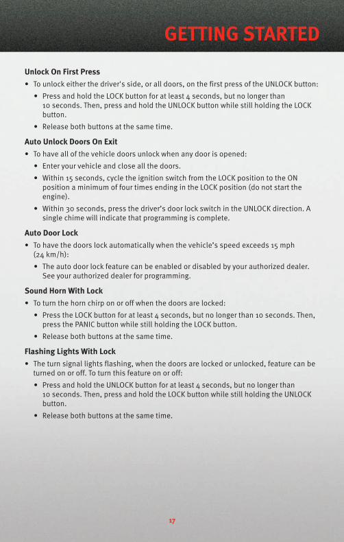
Unlock On First Press• To unlock either the driver's side, or all doors, on the first press of the UNLOCK button:
• Press and hold the LOCK button for at least 4 seconds, but no longer than10 seconds. Then, press and hold the UNLOCK button while still holding the LOCKbutton.
• Release both buttons at the same time.
Auto Unlock Doors On Exit• To have all of the vehicle doors unlock when any door is opened:
• Enter your vehicle and close all the doors.
• Within 15 seconds, cycle the ignition switch from the LOCK position to the ONposition a minimum of four times ending in the LOCK position (do not start theengine).
• Within 30 seconds, press the driver’s door lock switch in the UNLOCK direction. Asingle chime will indicate that programming is complete.
Auto Door Lock• To have the doors lock automatically when the vehicle’s speed exceeds 15 mph
(24 km/h):
• The auto door lock feature can be enabled or disabled by your authorized dealer.See your authorized dealer for programming.
Sound Horn With Lock• To turn the horn chirp on or off when the doors are locked:
• Press the LOCK button for at least 4 seconds, but no longer than 10 seconds. Then,press the PANIC button while still holding the LOCK button.
• Release both buttons at the same time.
Flashing Lights With Lock• The turn signal lights flashing, when the doors are locked or unlocked, feature can be
turned on or off. To turn this feature on or off:
• Press and hold the UNLOCK button for at least 4 seconds, but no longer than10 seconds. Then, press and hold the LOCK button while still holding the UNLOCKbutton.
• Release both buttons at the same time.
17
GETTING STARTED

TURN SIGNAL/LIGHTS LEVER
Headlights/Parking Lights/Automatic Headlights• Rotate the end of the lever to the first detent for parking lights , the second
detent for headlights and the third detent for AUTO.
• When set to AUTO, the system automatically turns the headlights on or off based onambient light levels.
Instrument Panel Dimmer• Rotate the center portion of the lever to the extreme bottom position to fully dim the
instrument panel lights and prevent the interior lights from illuminating when a dooris opened.
• Rotate the center portion of the lever up to increase the brightness of the instrumentpanel lights when the parking lights or headlights are on.
• Rotate the center portion of the lever upward to the next detent position to brightenthe odometer and radio controls when the parking lights or headlights are on.
• Rotate the center portion of the lever upward to the last detent to turn on the interiorlighting.
High Beam Operation• Push the lever forward to activate the high beams.
NOTE: For safe driving, turn off high beams when oncoming traffic is present to preventheadlight glare and as a courtesy to other motorists.
Fog Lights• Turn on the parking lights or low beam headlights and pull out the end of the lever.
Turn Signals/Lane Change Assist• Tap the lever up or down once and the turn signal (right or left) will flash three times
and automatically turn off.
OPERATING YOUR VEHICLE
18
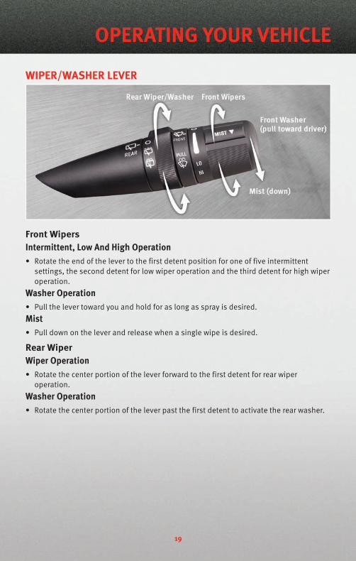
WIPER/WASHER LEVER
Front WipersIntermittent, Low And High Operation• Rotate the end of the lever to the first detent position for one of five intermittent
settings, the second detent for low wiper operation and the third detent for high wiperoperation.
Washer Operation• Pull the lever toward you and hold for as long as spray is desired.Mist• Pull down on the lever and release when a single wipe is desired.
Rear WiperWiper Operation• Rotate the center portion of the lever forward to the first detent for rear wiper
operation.Washer Operation• Rotate the center portion of the lever past the first detent to activate the rear washer.
19
OPERATING YOUR VEHICLE

SPEED CONTROL LEVERCruise ON/OFF• Push the ON/OFF button to activate the
Speed Control.
• CRUISE will appear on the instrumentcluster to indicate the Speed Control is on.
• Push the ON/OFF button a second time toturn the system off.
WARNING!Leaving the Electronic Speed Control system on when not in use is dangerous. Youcould accidentally set the system or cause it to go faster than you want. You could losecontrol and have an accident. Always leave the Electronic Speed Control system offwhen you are not using it.
Set• With Speed Control on, push down and release the lever to set a desired speed.
WARNING!Electronic Speed Control can be dangerous where the system cannot maintain aconstant speed. Your vehicle could go too fast for the conditions, and you could losecontrol. An accident could be the result. Do not use Electronic Speed Control in heavytraffic or on roads that are winding, icy, snow-covered or slippery.
Accel/Decel• Push and hold the lever up to accelerate or down to decelerate the vehicle; release the
lever to save the new set speed.• Once a speed is set, tapping the lever up or down will increase or decrease the set
speed approximately 1 mph (2 km/h).
Cancel• Pull the lever toward you or apply the brakes to cancel the set speed and maintain the
set speed in memory.• Push the ON/OFF button to turn the system off and erase the set speed memory.
Resume• To resume a previously selected speed in memory, push the lever up and release.
OPERATING YOUR VEHICLE
20
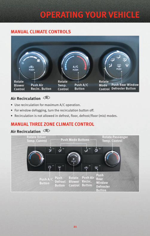
MANUAL CLIMATE CONTROLS
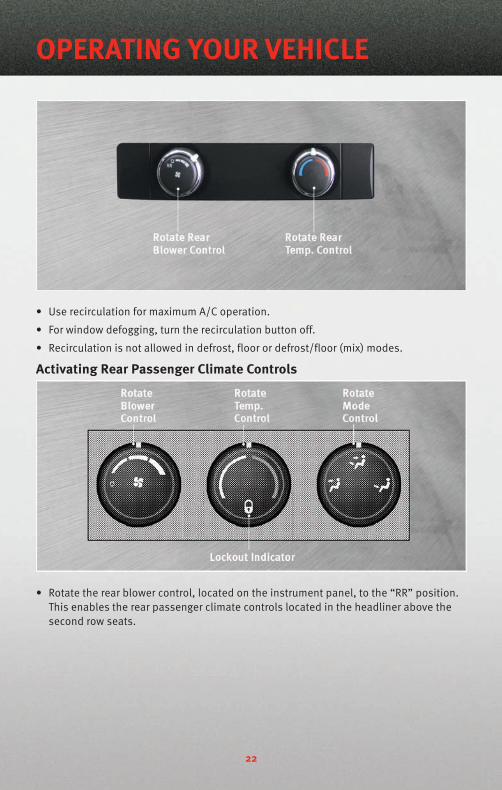
Air Recirculation• Use recirculation for maximum A/C operation.
• For window defogging, turn the recirculation button off.
• Recirculation is not allowed in defrost, floor, defrost/floor (mix) modes.
MANUAL THREE ZONE CLIMATE CONTROLAir Recirculation
21
OPERATING YOUR VEHICLE
• Use recirculation for maximum A/C operation.
• For window defogging, turn the recirculation button off.
• Recirculation is not allowed in defrost, floor or defrost/floor (mix) modes.
Activating Rear Passenger Climate Controls
• Rotate the rear blower control, located on the instrument panel, to the “RR” position.This enables the rear passenger climate controls located in the headliner above thesecond row seats.
OPERATING YOUR VEHICLE
22
TWO AND THREE ZONE AUTOMATIC TEMPERATURE CONTROL(ATC)
Automatic Operation• Push the AUTO button.
• Select the desired temperature by rotating the Temperature Controls for the driver orpassenger.
• The system will maintain the set temperature automatically.
Air Conditioning (A/C)• If the A/C button is pushed while in the AUTO mode, the indicator light may flash three
times to indicate the air conditioning is being controlled automatically.
23
OPERATING YOUR VEHICLE
SYNC Temperature Button• Push the SYNC button once to control driver and passenger temperatures
simultaneously. Push the SYNC button a second time to control the temperaturesindividually.
Air Recirculation• Use recirculation for maximum A/C operation.
• For window defogging, turn the recirculation button off.
• If the Recirculation button is pushed while in the AUTO mode, the indicator light mayflash three times to indicate the cabin air is being controlled automatically.
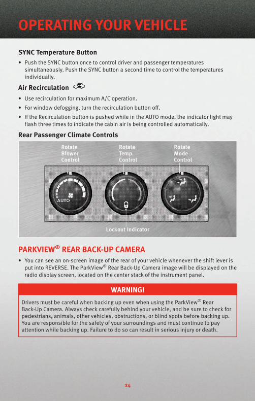
Rear Passenger Climate Controls
PARKVIEW® REAR BACK-UP CAMERA• You can see an on-screen image of the rear of your vehicle whenever the shift lever is
put into REVERSE. The ParkView® Rear Back-Up Camera image will be displayed on theradio display screen, located on the center stack of the instrument panel.
WARNING!Drivers must be careful when backing up even when using the ParkView® RearBack-Up Camera. Always check carefully behind your vehicle, and be sure to check forpedestrians, animals, other vehicles, obstructions, or blind spots before backing up.You are responsible for the safety of your surroundings and must continue to payattention while backing up. Failure to do so can result in serious injury or death.
OPERATING YOUR VEHICLE
24
POWER SUNROOF• The power sunroof switch is located on the overhead console.
WARNING!• Never leave children in a vehicle with the key in the ignition switch. Occupants,
particularly unattended children, can become entrapped by the power sunroofwhile operating the power sunroof switch. Such entrapment may result in seriousinjury or death.
• In an accident, there is a greater risk of being thrown from a vehicle with an opensunroof. You could also be seriously injured or killed. Always fasten your seat beltproperly and make sure all passengers are properly secured too.
• Do not allow small children to operate the sunroof. Never allow your fingers, otherbody parts, or any object to project through the sunroof opening. Injury may result.
Opening SunroofExpress• Press the switch rearward and release. The sunroof will fully open and stop
automatically.
Closing SunroofExpress• Press the switch forward and release. The sunroof will close automatically from any
position.
Manual Open/Close• Press and hold the switch rearward to open or forward to close the sunroof. Any
release of the switch will stop the movement, and the sunroof will remain in a partiallyopen or closed position until the switch is pressed again.
Venting Sunroof• Press and release the "V" button, and the sunroof will open to the vent position. This
is called “Express Vent” and will occur regardless of sunroof position. During ExpressVent operation, any movement of the switch will stop the sunroof.
Pinch Protection Feature• This feature will detect an obstruction in the opening of the sunroof during Express
Close operation. If an obstruction in the path of the sunroof is detected, the sunroofwill automatically return to the open position.
NOTE: Pinch protection is disabled while the switch is pressed and held during manualopening and closing of the sunroof.
25
OPERATING YOUR VEHICLE
WIND BUFFETING• Wind buffeting can be described as a helicopter-type percussion sound. If buffeting
occurs with the rear windows open, adjust the front and rear windows together.
• If buffeting occurs with the sunroof open, adjust the sunroof opening, or adjust anywindow. This will minimize buffeting.
OPERATING YOUR VEHICLE
26

NON-TOUCH-SCREEN RADIOSRES Radio
RES/RSC Radio
27
ELECTRONICS
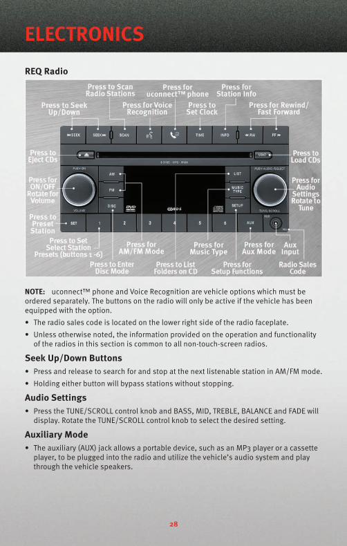
REQ Radio
NOTE: uconnect™ phone and Voice Recognition are vehicle options which must beordered separately. The buttons on the radio will only be active if the vehicle has beenequipped with the option.
• The radio sales code is located on the lower right side of the radio faceplate.
• Unless otherwise noted, the information provided on the operation and functionalityof the radios in this section is common to all non-touch-screen radios.
Seek Up/Down Buttons• Press and release to search for and stop at the next listenable station in AM/FM mode.
• Holding either button will bypass stations without stopping.
Audio Settings• Press the TUNE/SCROLL control knob and BASS, MID, TREBLE, BALANCE and FADE will
display. Rotate the TUNE/SCROLL control knob to select the desired setting.
Auxiliary Mode• The auxiliary (AUX) jack allows a portable device, such as an MP3 player or a cassette
player, to be plugged into the radio and utilize the vehicle’s audio system and playthrough the vehicle speakers.
ELECTRONICS
28
Clock Setting• Press and hold the TIME button until the hours blink; turn the TUNE/SCROLL control
knob to set the hours.
• Press the TUNE/SCROLL control knob until the minutes begin to blink; turn theTUNE/SCROLL control knob to set the minutes.
• Press the TUNE/SCROLL control knob to save the time change.
• To exit, press any button/knob or wait five seconds.
Station Presets• Press the SET/RND button once and SET 1 will show in the display. Then select the
button (1–6).
• A second station may be added to each push button. Press the SET/RND button twiceand SET 2 will show in the display, then select button (1–6).
How To Load Multiple CD's / DVD's
REQ Radio Only• Press the LOAD button and then push the button with the corresponding number (1–6)
where the CD is being loaded. The radio will display PLEASE WAIT and prompt when toINSERT DISC.
• After the radio displays INSERT DISC, insert the CD into the player. The radio displaywill show LOADING DISC when the disc is loading and “READING DISC” when the radiois reading the disc.
• Press the eject button and then the corresponding number (1–6) to eject the desireddisc.
29
ELECTRONICS

AM/FM/CD NAVIGATION RADIO
NOTE: uconnect™ phone and Voice Recognition are vehicle options which must beordered separately. The buttons on the radio will only be active if the vehicle has beenequipped with the option.
Seek Up / Down• Press to seek through radio stations in AM, FM, or SAT bands. Seek through tracks in
CD or iPod® modes or through songs in the HDD playlist.
JOYSTICK Operation• Move the JOYSTICK to move the cursor on the screen while in any mode.
• Press the center of the JOYSTICK to select highlighted menu items.
Center Control Knob• Rotate the CENTER CONTROL knob to scroll through lists, to adjust the slider right or
left and up or down or to zoom in/out of navigation maps.
Audio Settings• Press the AUDIO/TUNE knob, then use the CENTER CONTROL knob to highlight one of
the audio settings.
• Press the JOYSTICK, then rotate the CENTER CONTROL knob to adjust the audio setting.
• Press the JOYSTICK again to exit the setting.
• Press the AUDIO/TUNE knob to return to the previous screen.
ELECTRONICS
30
Clock Setting• Turn the radio on, then press the Time button to access the Time Settings screen.
• Turn the CENTER CONTROL knob until USER TIME is highlighted, then press theJOYSTICK to select the USER TIME option.
• To adjust the hours, turn the CENTER CONTROL knob to highlight SET HOURS, thenpress the JOYSTICK to select the setting.
• Turn the CENTER CONTROL knob to adjust the hours, then press the JOYSTICK to savethe setting.
• To adjust the minutes turn the CENTER CONTROL knob to highlight SET MINUTES, thenpress the JOYSTICK to select the setting.
• Turn the CENTER CONTROL knob to adjust the minutes, then press the JOYSTICK tosave the setting.
Store Radio Presets• Press the RADIO button to select the desired AM, FM or SAT radio band.
• Find the station to store by either pressing the SEEK UP/DOWN buttons, or touch theSCAN button or rotate the TUNE knob to change the currently playing station.
• Once the station is found, press the SET button followed by a preset button (1–6). Tostore the current station in one of the presets 7–12, press the SET button twicefollowed by a preset button (1–6).
Hard Disc Drive Operation
Copy Complete Audio Disc To Hard-Drive• Insert and select a disc, then press the MENU button.
• Select COPY DISC, then press the JOYSTICK to start the copy process.
Copying from USB• Insert a USB device, then select IMPORT MUSIC.
• Check-mark the desired music, titles, folders or Select All.
• Highlight IMPORT SELECTED MUSIC, then press the JOYSTICK to start the copy process.
Copy pictures to the Hard-Drive• Press the MENU button, then select the MY FILES function.
• Select MY PICTURES, then highlight ADD PICTURE and press the JOYSTICK.
• Select FROM DISC or FROM USB, then insert either a Disc or a USB devise.
• Select IMPORT PICTURES and press the JOYSTICK, then select the desired picture andpress the JOYSTICK to begin the copy process.
• Select YES to confirm your selection.
31
ELECTRONICS
Navigation• Navigation radios require digital data from a navigation database. The data in the
navigation database is licensed from Navigation Technologies®. Not all roads aredigitized.
• For software updates, visit http://www.chrysler.com/en/owners/mygig/ website, visithttp://www.navteq.com website, or contact your authorized dealer for the latestavailable software.
NOTE: Many features of this radio are speed dependent. For your own safety, it is notpossible to use the predictive speller to enter a name (e.g., street name) while thevehicle is in motion. Pull over at a safe location to complete your task.
• The Navigation system receives GPS signals from satellites to display the position ofyour vehicle.
New Destination• Press the NAV button to access the navigation menu, then select DESTINATION ENTRY.
• Select NEW DESTINATION, then rotate the CENTER CONTROL knob and press theJOYSTICK to select to the destination of your choice.
Program/Storing Home Address• Press the NAV hard-key to access the Navigation MAIN MENU.
• Rotate the CENTER CONTROL knob to highlight GUIDE ME HOME, then press theJOYSTICK to select.
• Rotate the CENTER CONTROL knob to highlight YES (only if home address has neverbeen set) in the next screen and press the JOYSTICK to access the ENTER HOMEADDRESS menu.
• Select STREET ADDRESS and press the JOYSTICK to confirm.
• Select INPUT STREET NAME and press the JOYSTICK to confirm, then enter your streetname into the predictive speller.
• Select CONTINUE and enter your address into the predictive speller; then selectCONTINUE again.
• Select OK to save your home address.
• Change the Country or State or Province as required by highlighting and selecting theappropriate folder on the screen and pressing LIST or entering the information into thepredictive speller, then press the JOYSTICK to confirm your selection.
Change Stored Home Address• Press the MENU button, then select MY FILES.
• Select MY ADDRESS BOOK, then select the HOME folder.
• In the HOME folder select EDIT HOME to change and/or clear address.
• Select STREET ADDRESS and press the JOYSTICK to confirm.
• Select INPUT STREET NAME and press the JOYSTICK to confirm, then enter your streetname into the predictive speller.
ELECTRONICS
32

• Select CONTINUE and enter your address into the predictive speller; then selectCONTINUE again.
• Select OK to save your home address.
Guide Me Home• Press the NAV button to access the Navigation Main Menu.
• Rotate the CENTER CONTROL knob to highlight GUIDE ME HOME, then press theJOYSTICK to select and to route you back to your home destination from your currentlocation.
Map• Press the NAV button to access the navigation MAIN MENU.
• Press the NAV button again to toggle between the navigation MAIN MENU and thenavigation MAP.
33
ELECTRONICS

AM/FM/CD MULTIMEDIA TOUCH-SCREEN RADIO
NOTE: uconnect™ phone and Voice Recognition are vehicle options which must beordered separately. The buttons on the radio will only be active if the vehicle has beenequipped with the option.
SCAN• Touch the SCAN soft-key to change the currently playing station in AM, FM or SAT
bands.
Clock Setting• Turn the radio ON, then touch the screen where the time is displayed.• To adjust hours, touch either the HOUR FORWARD or HOUR BACKWARD soft-key.• To adjust the minutes, touch either the MINUTE FORWARD or MINUTE BACKWARD
soft-key.• To save the new time setting, touch the screen where the word “Save” is displayed.
Store Radio Presets• Press the RADIO hard-key repeatedly until AM FM SAT is displayed in the upper left
corner of the screen.• Select the radio band by touching either the AM, FM, or SAT soft-key.• Find the station to store by either pressing the SEEK UP/DOWN soft-keys, or touch the
SCAN soft-key, DIRECT TUNE soft-key or the left and right arrows.• Once the station is found, touch and hold one of the PRESET soft-keys in the list to the
right until you hear a confirmation beep.
ELECTRONICS
34
Hard Disc Drive Operation
Copy Complete Audio Disc To Hard-Drive• Press the OPEN/CLOSE hard-key and insert a disc, then press the MENU hard-key.
• Touch the MY FILES soft-key, then select MY MUSIC.
• Touch the IMPORT MUSIC soft-key, then touch the FROM DISC soft-key in the nextscreen to start the process.
Copying From USB• Insert a USB device, then select MY MUSIC.
• Touch the IMPORT MUSIC FILES soft-key, then touch the From USB soft-key in the nextscreen.
• Select the folders or titles you would like to copy, then touch the DONE soft-key tostart the copy process.
Copy Pictures To The Hard-Drive• Touch the MY FILES hard-key to go to the MANAGE MY FILES screen, then insert either a
CD or a USB Stick containing your pictures.
• Touch the MY PICTURES soft-key to get an overview of the currently stored images.
• Touch one of the Add Pictures soft-keys, then select the type of media inserted.
• Use the PAGE soft-keys to page through a list of pictures and touch the picture youwould like to import.
• Confirm your selection by touching the YES soft-key. The imported picture is nowavailable in the MANAGE MY PICTURES screen.
• In order to display the imported picture in the radio screen, touch the desired picturesoft-key.
• Select this picture by pressing the SET AS DEFAULT soft-key. A check mark indicatesthe currently used picture.
Cleaning Your Touch-Screen-Radio• Do not spray any liquid or caustic chemicals directly on the screen. Use a clean and
dry micro fiber lens cleaning cloth in order to clean the touch-screen.
• If necessary, use a lint-free cloth dampened with a cleaning solution such as isopropylalcohol or an isopropyl alcohol and water solution ratio of 50:50. Be sure to follow thesolvent manufacturer's precautions and directions.
35
ELECTRONICS

REMOTE AUDIO CONTROLS• The switches are located on the rear surface
of the steering wheel.
Right Switch• Press the switch up or down to increase and
decrease the volume.
• Press the button in the center to changemodes AM/FM/CD/SAT.
Left Switch• Press the switch up or down to search for
the next listenable station or select the nextor previous CD track.
• Press the button in the center to select thenext preset station (Radio) or to change CDsif equipped with a CD Changer.
VIDEO ENTERTAINMENT SYSTEM (VES)™System Operation• The screen is located on the headliner
behind the front seat. To lower the screen,press the release button located in thecenter of the console rear of the screen.
• The system may be controlled by the frontseat occupants using the touch-screen ofthe radio or by the JOYSTICK on the REUradio. The rear seat occupants may controlthe system using the remote.
• The video screen displays information in a split screen format. The left side of thescreen is referred to as Channel 1 and the right side of the screen is referred to asChannel 2. All modes except video modes are displayed in a split screen format.
• To use the headphones, press the power button located on the right ear cup. Selectthe channel on the headphones (Channel 1 or 2) that corresponds to the channelselected on the VES™ screen.
ELECTRONICS
36
Operation Of The RBZ Radio• To view a DVD press the OPEN/CLOSE hard-key and insert the disc. Playback will begin
automatically after the DVD is recognized by the disc drive. If playback does not beginautomatically follow these steps:
• Press the MENU hard-key, then touch the REAR VES™ soft-key. If a chapter list appearson the right side of the screen touch the HIDE LIST soft-key to display the Rear VES™Control screen.
• Touch the 1 soft-key to select an audio channel then touch the DISC soft-key in theMEDIA column.
• SIRIUS Backseat TV™
• Press the MENU hard-key, then touch the REAR VES™ soft-key. If a chapter listappears on the right side of the screen touch the HIDE LIST soft-key to display theRear VES™ Control screen
• Touch the 1 soft-key to select an audio channel then touch the TV soft-key in theRADIO column to select SIRIUS Backseat TV™.
Operation Of The REU Radio• To view a DVD video insert a video disc. Playback will begin automatically after the
DVD is recognized by the disc drive. If playback does not begin automatically followthese steps:
• Press the MENU button, then turn the CENTER CONTROL knob and press the JOYSTICKto select VES™ CONTROLS.
• Select channel 1 or 2, then select DISC.• Turn the CENTER CONTROL knob to select FUNCTIONS, then select SHOW VIDEO.• SIRIUS Backseat TV™
• Press the RADIO button, to highlight SATV, then press the LIST button to display alist of available video channels.
• Select the desired channel, then press the MENU button and select SHOW VIDEO.
Operation Of The Remote• The remote control operates similarly to any DVD remote you have used before and
allows the rear seat passengers to change stations, tracks, discs and audio/videomodes.
• The remote control is designed to control either channel by using the selector switchlocated on the right side of the remote.
• Pressing the power button will turn the VES™ system ON/OFF.• Pressing the MODE button causes the Mode Selection menu to appear on the VES™
screen. Use the remote control arrow buttons to scroll through the available modes,then press ENTER to select the desired mode.
• SIRIUS Backseat TV™
• To view SIRIUS Backseat TV™ set the remote control channel selector switch tochannel 1. Press the MODE button, then using the arrow buttons select TV and pressenter.
37
ELECTRONICS
Auxiliary Audio/Video Input Jacks• The Aux jacks are located on the rear of the center console.
• Connect the video game or other external media devices to the AUX jacks following thecolor coding for VES™ jacks.
• Using either the touch-screen radio or remote control, select AUX from the Rear VES™Control or Mode Selection screen.
• Refer to “uconnect™ studios” in the uconnect™ user's manual on the DVD for furtherdetails.
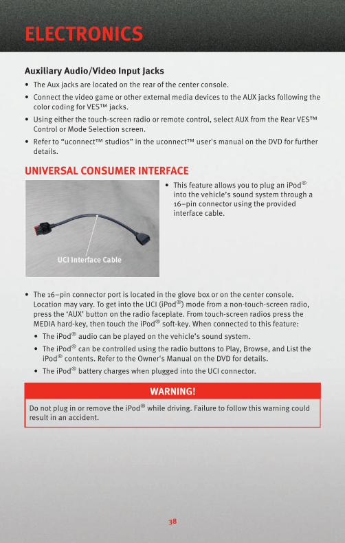
UNIVERSAL CONSUMER INTERFACE• This feature allows you to plug an iPod®
into the vehicle’s sound system through a16–pin connector using the providedinterface cable.
• The 16–pin connector port is located in the glove box or on the center console.Location may vary. To get into the UCI (iPod®) mode from a non-touch-screen radio,press the ‘AUX’ button on the radio faceplate. From touch-screen radios press theMEDIA hard-key, then touch the iPod® soft-key. When connected to this feature:
• The iPod® audio can be played on the vehicle’s sound system.
• The iPod® can be controlled using the radio buttons to Play, Browse, and List theiPod® contents. Refer to the Owner's Manual on the DVD for details.
• The iPod® battery charges when plugged into the UCI connector.
WARNING!Do not plug in or remove the iPod® while driving. Failure to follow this warning couldresult in an accident.
ELECTRONICS
38
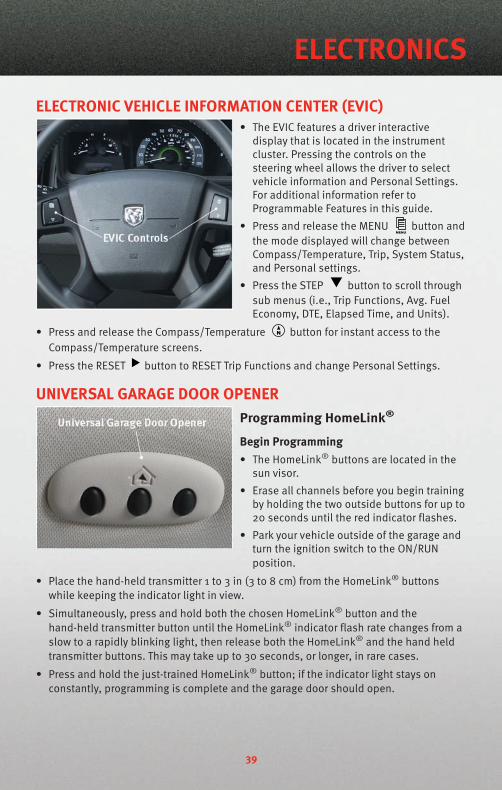
ELECTRONIC VEHICLE INFORMATION CENTER (EVIC)• The EVIC features a driver interactive
display that is located in the instrumentcluster. Pressing the controls on thesteering wheel allows the driver to selectvehicle information and Personal Settings.For additional information refer toProgrammable Features in this guide.
• Press and release the MENU button andthe mode displayed will change betweenCompass/Temperature, Trip, System Status,and Personal settings.
• Press the STEP button to scroll throughsub menus (i.e., Trip Functions, Avg. FuelEconomy, DTE, Elapsed Time, and Units).
• Press and release the Compass/Temperature button for instant access to theCompass/Temperature screens.
• Press the RESET button to RESET Trip Functions and change Personal Settings.
UNIVERSAL GARAGE DOOR OPENERProgramming HomeLink®
Begin Programming• The HomeLink® buttons are located in the
sun visor.
• Erase all channels before you begin trainingby holding the two outside buttons for up to20 seconds until the red indicator flashes.
• Park your vehicle outside of the garage andturn the ignition switch to the ON/RUNposition.
• Place the hand-held transmitter 1 to 3 in (3 to 8 cm) from the HomeLink® buttonswhile keeping the indicator light in view.
• Simultaneously, press and hold both the chosen HomeLink® button and thehand-held transmitter button until the HomeLink® indicator flash rate changes from aslow to a rapidly blinking light, then release both the HomeLink® and the hand heldtransmitter buttons. This may take up to 30 seconds, or longer, in rare cases.
• Press and hold the just-trained HomeLink® button; if the indicator light stays onconstantly, programming is complete and the garage door should open.
39
ELECTRONICS
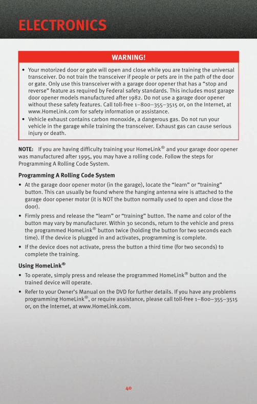
WARNING!• Your motorized door or gate will open and close while you are training the universal
transceiver. Do not train the transceiver if people or pets are in the path of the dooror gate. Only use this transceiver with a garage door opener that has a “stop andreverse” feature as required by Federal safety standards. This includes most garagedoor opener models manufactured after 1982. Do not use a garage door openerwithout these safety features. Call toll-free 1–800–355–3515 or, on the Internet, atwww.HomeLink.com for safety information or assistance.
• Vehicle exhaust contains carbon monoxide, a dangerous gas. Do not run yourvehicle in the garage while training the transceiver. Exhaust gas can cause seriousinjury or death.
NOTE: If you are having difficulty training your HomeLink® and your garage door openerwas manufactured after 1995, you may have a rolling code. Follow the steps forProgramming A Rolling Code System.
Programming A Rolling Code System• At the garage door opener motor (in the garage), locate the “learn” or “training”
button. This can usually be found where the hanging antenna wire is attached to thegarage door opener motor (it is NOT the button normally used to open and close thedoor).
• Firmly press and release the “learn” or “training” button. The name and color of thebutton may vary by manufacturer. Within 30 seconds, return to the vehicle and pressthe programmed HomeLink® button twice (holding the button for two seconds eachtime). If the device is plugged in and activates, programming is complete.
• If the device does not activate, press the button a third time (for two seconds) tocomplete the training.
Using HomeLink®
• To operate, simply press and release the programmed HomeLink® button and thetrained device will operate.
• Refer to your Owner’s Manual on the DVD for further details. If you have any problemsprogramming HomeLink®, or require assistance, please call toll-free 1–800–355–3515or, on the Internet, at www.HomeLink.com.
ELECTRONICS
40
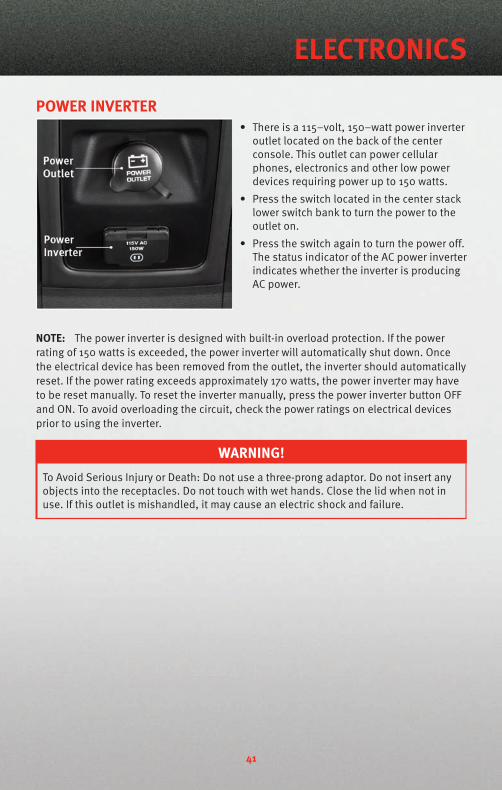
POWER INVERTER• There is a 115–volt, 150–watt power inverter
outlet located on the back of the centerconsole. This outlet can power cellularphones, electronics and other low powerdevices requiring power up to 150 watts.
• Press the switch located in the center stacklower switch bank to turn the power to theoutlet on.
• Press the switch again to turn the power off.The status indicator of the AC power inverterindicates whether the inverter is producingAC power.
NOTE: The power inverter is designed with built-in overload protection. If the powerrating of 150 watts is exceeded, the power inverter will automatically shut down. Oncethe electrical device has been removed from the outlet, the inverter should automaticallyreset. If the power rating exceeds approximately 170 watts, the power inverter may haveto be reset manually. To reset the inverter manually, press the power inverter button OFFand ON. To avoid overloading the circuit, check the power ratings on electrical devicesprior to using the inverter.
WARNING!To Avoid Serious Injury or Death: Do not use a three-prong adaptor. Do not insert anyobjects into the receptacles. Do not touch with wet hands. Close the lid when not inuse. If this outlet is mishandled, it may cause an electric shock and failure.
41
ELECTRONICS

POWER OUTLETThere are two 12-volt power outlets located in the center console below the radio. Theoutlet on the top has power available when the ignition switch in the ON position. Theoutlet on the bottom has power available when the ignition switch is in the LOCK, ON, orACC position. A third 12-volt power outlet is located on the back of the center console.This outlet has power available when the ignition switch is in the LOCK, ON or ACCposition. A fourth fused 12-volt power outlet is located on the left quarter trim panel inthe cargo area. This outlet has power available when the ignition switch is in the ON orACC position.
NOTE: Do not exceed the maximum power of 160 Watts (13 Amps) at 12 Volts. If the 160Watt (13 Amp) power rating is exceeded the fuse protecting the system will need to bereplaced.
uconnect™ phone• The uconnect™ phone is a voice-activated, hands-free, in-vehicle communications
system.
• The uconnect™ phone allows you to dial a phone number with your cellular phoneusing simple voice commands.
• Please refer to uconnect™ phone in the uconnect™ User's Manual on the DVD forfurther details.
WARNING!• Any voice commanded system should be used only in safe driving conditions
following local laws and phone use. All attention should be kept on the roadwayahead. Failure to do so may result in an accident causing serious injury or death.
• Your phone must be turned on and paired to the uconnect™ phone to allow use ofthis vehicle feature in emergency situations, when the cellular phone has networkcoverage and stays paired to the uconnect™ phone.
NOTE: The uconnect™ phone requires a cellular phone equipped with the Bluetooth®
Hands-Free Profile, Version 0.96 or higher. For uconnect™ customer support, call1–877–855–8400.
Phone Pairing
NOTE: Pairing is a one-time initial setup before using the phone. You will also need tofollow the Bluetooth instructions in your cell phone user guide to complete the phonepairing setup.
• Press the Phone button to begin.
• Wait for the “ready” prompt and beep.
• (After the BEEP), say “uconnect setup”.
• (After the BEEP), say “phone pairing”.
ELECTRONICS
42
• (After the BEEP) say, “pair a phone”.
• Follow the audible prompts.
• You will be asked to create a four-digit PIN which you will later need to enter into yourphone (typically..settings, bluetooth, device, list, new).
• You will then be prompted to give the phone pairing a name (each phone pairedshould have a unique name).
• Next you will be asked to give this new pairing a priority of 1 thru 7 (up to sevenphones may be paired).
Making A Phone Call• Press the Phone button .
• (After the BEEP), say “dial” (or “call” to a name).
• (After the BEEP), say number (or name).
Phonebook (uconnect™ local) Edit• Press the Phone button .
• (After the BEEP), say “phonebook”.
• (After the BEEP), say “new entry” or “list names” or “delete”.
• Follow the prompts.
Receiving A Call – Accept (And End)• When an incoming call rings / is announced on uconnect™, press the Phone
button .
• To end a call, press the Phone button .
Mute (Or Unmute) Microphone During Call• During a call, press the Voice button .
• (After the BEEP), say “mute on” (or “mute off ”).
Transfer Ongoing Call Between Handset And Vehicle• During a call, press the Voice button .
• (After the BEEP), say “transfer call”.
Changing The Volume• Start a dialogue by pressing the Phone button , then adjust the volume during a
normal call.
• Use the radio ON/OFF VOLUME rotary knob to adjust the volume to a comfortable levelwhile the uconnect™ system is speaking. Please note the volume setting foruconnect™ is different than the audio system.
NOTE: To access the tutorial, press the uconnect™ hard-key. After the BEEP, say“tutorial”. Press any hard-key or touch the display to cancel the tutorial.
43
ELECTRONICS
VOICE RECOGNITION• The Voice Recognition (VR) system allows you to control your AM, FM radio, satellite
radio, disc player, and a memo recorder. When you press the VR button , you willhear a beep. The beep is your signal to give a command. If you do not say a commandwithin a few seconds, the system will present you with a list of options. If you everwish to interrupt the system while it lists options, press the VR button , listen forthe BEEP, and say your command.
• Please refer to uconnect™ tunes in the uconnect™ User's Manual on the DVD forfurther details.
Changing The Volume• Start a dialogue by pressing the VR button , then say a command (e.g., “tutorial”).
• Use the radio ON/OFF VOLUME rotary knob to adjust the volume to a comfortable levelwhile the Voice Recognition system is speaking. Please note the volume setting forVoice Recognition is different than the audio system.
WARNING!Any voice commanded system should be used only in safe driving conditions and allattention should be kept on the roadway ahead. Failure to do so may result in anaccident causing serious injury or death.
NOTE: To access the tutorial, press the VR button . After the BEEP, say “tutorial”.Press any hard-key or touch the display to cancel the tutorial.
ELECTRONICS
44
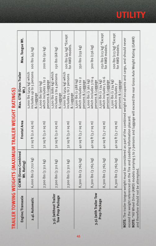
TRAI
LER
TOW
ING
WEI
GHT
S(M
AXIM
UM
TRAI
LER
WEI
GHT
RATI
NGS)
Engi
ne/T
rans
axle
GCW
R(G
ross
Com
bine
dW
t.Ra
ting)
Fron
talA
rea
Max
.GTW
(Gro
ssTr
aile
rW
t.)M
ax.T
ongu
eW
t.
2.4L
Auto
mat
ic6,
000
lbs
(272
2kg
)22
sqft
(2.0
sqm
)1,
000
lbs
(454
kg)w
hich
incl
udes
upto
5pe
rson
s&
Lugg
age
100
lbs
(45
kg)
3.5L
(with
outT
raile
rTo
wPr
epPa
ckag
e
7,30
0lb
s(3
311
kg)
32sq
ft(3
.0sq
m)
2,00
0lb
s(9
07kg
)w
hich
incl
udes
1to
2pe
rson
s&
Lugg
age
200
lbs
(91
kg)
7,30
0lb
s(3
311
kg)
32sq
ft(3
.0sq
m)
1,50
0lb
s(6
80kg
)whi
chin
clud
es3
to4
pers
ons
&Lu
ggag
e15
0lb
s(6
8kg
)
7,30
0lb
s(3
311
kg)
32sq
ft(3
.0sq
m)
1,00
0lb
s(4
54kg
)whi
chin
clud
es5
to7
pers
ons
&Lu
ggag
e
100
lbs
(45
kg)*
Exce
ptfo
rAW
Dm
odel
s.
3.5L
(with
Trai
lerT
owPr
epPa
ckag
e
8,30
0lb
s(3
765
kg)
40sq
ft(3
.7sq
m)
3,50
0lb
s(1
588
kg)
whi
chin
clud
es1
to2
pers
ons
&Lu
ggag
e35
0lb
s(1
59kg
)
8,30
0lb
s(3
765
kg)
40sq
ft(3
.7sq
m)
3,00
0lb
s(1
361
kg)
whi
chin
clud
es3
to4
pers
ons
&Lu
ggag
e30
0lb
s(1
36kg
)
8,30
0lb
s(3
765
kg)
40sq
ft(3
.7sq
m)
2,50
0lb
s(1
134
kg)
whi
chin
clud
es5
to6
pers
ons
&Lu
ggag
e
250
lbs
(113
kg)*
Exce
ptfo
rAW
Dm
odel
s.
8,30
0lb
s(3
765
kg)
40sq
ft(3
.7sq
m)
2,50
0lb
s(1
134
kg)
whi
chin
clud
es7
pers
ons
&Lu
ggag
e
100
lbs
(113
kg)*
Exce
ptfo
rAW
Dm
odel
s.
NOTE
:The
trai
lert
ongu
ew
eigh
tmus
tbe
cons
ider
edas
part
ofth
eco
mbi
ned
wei
ghto
focc
upan
tsan
dca
rgo,
and
shou
ldne
ver
exce
edth
ew
eigh
tref
eren
ced
onth
eTi
rean
dLo
adin
gIn
form
atio
npl
acar
d.NO
TE:*
AllW
heel
Driv
e(A
WD
)mod
els
carr
ying
5to
7pe
rson
san
dlu
ggag
ew
illex
ceed
the
rear
Gro
ssAx
leW
eigh
tRat
ing
(GAW
R)an
dth
eref
ore
shou
ldno
tbe
atte
mpt
ed.
45
UTILITY
RECREATIONAL TOWING(BEHIND MOTORHOME,ETC.)Towing This Vehicle BehindAnother Vehicle (Flat TowingWith All Four Wheels On TheGround)Recreational towing for this vehicle isnot recommended.
NOTE: If the vehicle requires towing,make sure all four wheels are off theground.
BRAKE/TRANSAXLEINTERLOCK MANUALOVERRIDE• The manual override may be used in
the event that the shift lever shouldfail to move from PARK with the KeyFob in the ON position and the brakepedal pressed.
• To operate the shift lock manualoverride, perform the following steps:
• Firmly apply the parking brake.
• Insert the ignition Key Fob into theignition switch and rotate it to theON position.
• Remove the cubby bin liner locatedin the center console behind theshift lever.
• Insert a screwdriver or similarsmall tool into the hole at the frontof the cubby bin and push themanual override release leverforward.
• While holding the release leverforward, move the shift lever fromPARK to NEUTRAL.
• Release the manual override.
• Have your vehicle inspected by yourlocal authorized dealer if the shiftlock manual override has been used.
UTILITY
46
24 HOUR TOWING ASSISTANCE• Dial toll-free 1-800-521-2779.• Provide your name, vehicle identification number and license plate number.• Provide your location, including telephone number, from which you are calling.• Briefly describe the nature of the problem and answer a few simple questions.• You will be given the name of the service provider and an estimated time of arrival. If
you feel you are in an “unsafe situation”, please let us know. With your consent, wewill contact local police or safety authorities.
INSTRUMENT CLUSTER WARNING LIGHTS- Electronic Stability Program (ESP) Indicator Light
• If this indicator light flashes during acceleration, apply as little throttle as possible.While driving, ease up on the accelerator. Adapt your speed and driving to theprevailing road conditions. To improve the vehicles traction when starting off in deepsnow, sand or gravel, it may be desirable to switch the ESP system off.
- Tire Pressure Monitoring System (TPMS) Light• A Tire Pressure Monitoring Light and a “low tire” message will display in your
instrument cluster along with an audible chime if one or more of your vehicle’s fourroad tires are significantly under-inflated.
• Check the inflation pressure of each tire and inflate to the recommended pressure foryour vehicle. The tire pressures recommended for your vehicle are found on the “Tireand Loading Information” label located on the driver’s side door opening. The TPMSlight should not be used as a tire pressure gauge when adjusting your tire pressure.
• It is recommended that you check the tire pressure in the morning when tires are cool;inflate each tire to the recommended pressure for your vehicle. The light will turn offafter your vehicle’s tire pressures are properly inflated and the pressure has beenrecognized. The vehicle may need to be driven for up to 20 minutes above 15 mph(25 km/h) before the light will turn off.
• Temperature changes can affect tire pressure, causing the TPMS light to turn on. Tirepressures will also increase as the vehicle is driven – this is normal and you shouldnot adjust for this increased pressure.
• Driving on under-inflated tires reduces your vehicle’s fuel efficiency and tire tread life.If a spare tire is in use on the vehicle, the TPMS light may turn on.
- Engine Temperature Warning Light• This light warns of an overheated engine condition.
• If the light turns on and a warning chime sounds while driving, safely pull over andstop the vehicle. If the A/C system is on, turn it off. Also, shift the transmission intoNEUTRAL and idle the vehicle. If the temperature reading does not return to normal,turn the engine off immediately.
• We recommend that you do not operate the vehicle or engine damage will occur. Havethe vehicle serviced immediately.
47
WHAT TO DO IN EMERGENCIES
WARNING!A hot engine cooling system is dangerous. You or others could be badly burned bysteam or boiling coolant. You may want to call an authorized dealership for service ifyour vehicle overheats.
BRAKE - Brake Warning Light• The Brake Warning light illuminates when there is either a system malfunction or the
parking brake is applied. If the light is on and the parking brake is not applied, itindicates a possible brake hydraulic malfunction, brake booster problem or anAnti-Lock Brake System problem.
• We recommend you drive to the nearest Service Center and have the vehicle servicedimmediately.
WARNING!Driving a vehicle with the red brake light on is dangerous. Part of the brake systemmay have failed. It will take longer to stop the vehicle. You could have an accident.Have the vehicle checked immediately.
- Malfunction Indicator Light (MIL)• Certain conditions, such as a loose or missing gas cap, poor fuel quality, etc., may
illuminate the MIL after engine start. The vehicle should be serviced if the light stayson through several typical driving cycles. In most situations, the vehicle will drivenormally and not require towing.
• If the MIL flashes when the engine is running, serious conditions may exist that couldlead to immediate loss of power or severe catalytic converter damage. We recommendyou do not operate the vehicle. Have the vehicle serviced as soon as possible if thisoccurs.
- Electronic Stability Program (ESP) Indicator Light/Brake AssistSystem (BAS) Warning Light• If the ESP/BAS warning light comes on continuously with the engine running, a
malfunction has been detected.
• If this light remains on after several ignition cycles, and the vehicle has been drivenseveral miles (kilometers) at speeds greater than 30 mph (48 km/h), we recommendyou drive to the nearest Service Center as soon as possible to have the problemdiagnosed and corrected.
- Charging System Light• This light shows the status of the electrical charging system. If the charging system
light remains on, it means that the vehicle is experiencing a problem with the chargingsystem.
WHAT TO DO IN EMERGENCIES
48
• We recommend you do not continue driving if the charging system light is on. Have thevehicle serviced immediately.
- Oil Pressure Warning Light• This light indicates low engine oil pressure. If the light turns on while driving, stop the
vehicle and shut off the engine as soon as possible. A chime will sound for fourminutes when this light turns on.
• We recommend you do not operate the vehicle or engine damage will occur. Have thevehicle serviced immediately.
- Anti-Lock Brake (ABS) Light• This light monitors the Anti-Lock Brake System (ABS).
• If the light is not on during starting, stays on, or turns on while driving, we recommendyou drive to the nearest Service Center and have the system serviced as soon aspossible.
- Electronic Throttle Control (ETC) Light• This light informs you of a problem with the Electronic Throttle Control (ETC) system.
• If a problem is detected, the light will come on while the engine is running. Cycle theignition when the vehicle has completely stopped and the shift lever is placed in thePARK position; the light should turn off.
• If the light remains lit with the engine running, your vehicle will usually be drivable;however, see an authorized dealer for service as soon as possible. If the light isflashing when the engine is running, immediate service is required and you mayexperience reduced performance, an elevated/rough idle or engine stall and yourvehicle may require towing.
- Airbag Warning Light• If the light is not on during starting, stays on, or turns on while driving, we recommend
you drive to the nearest Service Center and have the system serviced as soon aspossible.
- All-Wheel Drive (AWD) Failure Indicator Light• If the light stays on or comes on during driving, it means that the 4WD system is not
functioning properly and that service is required. We recommend you drive to thenearest service center as soon as possible.
Fuel Cap/Loose Gas Cap Message• If a “gas cap” message (shown as gASCAP) appears, tighten the gas cap until a
“clicking” sound is heard.
• Press the odometer reset button to turn the message off.
• If the message continues to appear for more than three days after tightening the gascap, see your dealer.
49
WHAT TO DO IN EMERGENCIES
Oil Change IndicatorMessage• If an “oil change” message (shown as CHAngE OIL) appears and a single chime
sounds, it is time for your next required oil change.Resetting The Light After Servicing• Turn the ignition switch to the ON/RUN position (do not start engine).
• Fully depress the accelerator pedal three times within 10 seconds.
• Turn the ignition switch to the OFF/LOCK position.
IF YOUR ENGINE OVERHEATS• In any of the following situations, you can reduce the potential for overheating by
taking the appropriate action.
• On the highways — slow down.
• In city traffic — while stopped, shift transmission into NEUTRAL, but do not increaseengine idle speed.
NOTE: There are steps that you can take to slow down an impending overheatcondition:• If your air conditioner (A/C) is on, turn it off. The A/C system adds heat to the engine
cooling system and turning the A/C off can help remove this heat.• You can also turn the Temperature Control to maximum heat, the Mode Control to floor
and the Fan Control to high. This allows the heater core to act as a supplement to theradiator and aids in removing heat from the engine cooling system.
• If the temperature reading does not return to normal, turn the engine off immediately.• We recommend that you do not operate the vehicle or engine damage will occur. Have
the vehicle serviced immediately.
CAUTION!Driving with a hot cooling system could damage your vehicle. If the temperature gaugereads HOT (H), pull over and stop the vehicle. Idle the vehicle with the air conditionerturned off until the pointer drops back into the normal range. If the pointer remains onHOT (H), and you hear continuous chimes, turn the engine off immediately and call forservice.
WARNING!You or others can be badly burned by hot engine coolant (antifreeze) or steam fromyour radiator. If you see or hear steam coming from under the hood, do not open thehood until the radiator has had time to cool. Never try to open a cooling systempressure cap when the radiator or coolant bottle is hot.
WHAT TO DO IN EMERGENCIES
50
JACKING AND TIRE CHANGING
WARNING!• Do not attempt to change a tire on the side of the vehicle close to moving traffic.
Pull far enough off the road to avoid the danger of being hit when operating the jackor changing the wheel.
• Getting under a jacked-up vehicle is dangerous. The vehicle could slip off the jackand fall on you. You could be crushed. Never get any part of your body under avehicle that is on a jack. If you need to get under a raised vehicle, take it to aservice center where it can be raised on a lift.
• The jack is designed to use as a tool for changing tires only. The jack should not beused to lift the vehicle for service purposes. The vehicle should be jacked on a firmlevel surface only. Avoid ice or slippery areas.
• If it is necessary to retrieve the spare tire from under the vehicle on the side of thevehicle close to moving traffic, pull far enough off the road to avoid the danger ofbeing hit.
WARNING!• The compact spare tire is for emergency use only. Installation of this compact spare
tire affects vehicle handling.• Do not drive more than 50 mph (80 km/h) with a compact spare tire.• Keep the compact spare tire inflated to the cold tire inflation pressure, listed on
either your tire placard or limited use spare tire and wheel assembly.• Replace (or repair) the original tire at the first opportunity and reinstall it on your
vehicle. Failure to do so could result in loss of vehicle control.
51
WHAT TO DO IN EMERGENCIES

Jack Location
• The jack and jack-handle are stowed underneath a cover in the rear storage bin in thecargo area.
• Remove the pouch containing the scissors jack, jack handle, and tools.
Spare Tire Stowage
NOTE: On Seven-Passenger Models, fold the third-row passenger seats flat. This willprovide more space when accessing the jacking tools and when operating the winchmechanism.
• To remove the spare tire, remove the jack-handle components from the storage bin inthe cargo area and assemble them.
• Lower the spare tire by turning the spare tire drive nut, located in the jack storagearea, counterclockwise with the jack-handle assembly until the spare tire is on theground with enough cable slack to allow you to pull the spare tire out from underneaththe vehicle.
• Raise the tire upright so the tire’s tread is on the ground and tilt the retainer at the endof the winch cable to remove it from the center of the wheel.
Preparations For Jacking• Park on a firm, level surface. Avoid ice or slippery areas.
• Set the parking brake and place the shift lever into PARK.
• Turn the ignition to LOCK and turn on the Hazard Warning flasher.
WHAT TO DO IN EMERGENCIES
52

• Block both the front and rear of the wheel diagonally opposite of the jacking position.For example, if changing the right front tire, block the left rear wheel.
NOTE: Passengers should not remain in thevehicle when the vehicle is being jacked.
Jacking And Tire Changing Instructions
WARNING!Carefully follow these tire changing procedures to help prevent personal injury ordamage to your vehicle: Always park on a firm, level surface as far from the edge ofthe roadway as possible before raising the vehicle.
• Remove the spare tire, jack and tools from the stored location.
• Loosen (but do not remove) the wheel lug nuts by turning them to the left one turnwhile the wheel is still on the ground.
• Assemble the jack and jacking tools. Connect the jack handle driver to the extension,then to the lug wrench.
53
WHAT TO DO IN EMERGENCIES
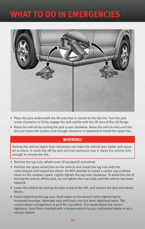
• Place the jack underneath the lift area that is closest to the flat tire. Turn the jackscrew clockwise to firmly engage the jack saddle with the lift area of the sill flange.
• Raise the vehicle by turning the jack screw clockwise. Raise the vehicle only until thetire just clears the surface and enough clearance is obtained to install the spare tire.
WARNING!Raising the vehicle higher than necessary can make the vehicle less stable and causean accident. It could slip off the jack and hurt someone near it. Raise the vehicle onlyenough to remove the tire.
• Remove the lug nuts, wheel cover (if equipped) and wheel.
• Position the spare wheel/tire on the vehicle and install the lug nuts with thecone-shaped end toward the wheel. Do NOT attempt to install a center cap or wheelcover on the compact spare. Lightly tighten the lug nuts clockwise. To avoid the risk offorcing the vehicle off the jack, do not tighten the nuts fully until the vehicle has beenlowered.
• Lower the vehicle by turning the jack screw to the left, and remove the jack and wheelblocks.
• Finish tightening the lug nuts. Push down on the wrench while tightening forincreased leverage. Alternate nuts until each one has been tightened twice. Thecorrect wheel nut tightness is 95 ft lbs (130 N•m). If in doubt about the correcttightness, have them checked with a torque wrench by your authorized dealer or at aservice station.
WHAT TO DO IN EMERGENCIES
54
WARNING!A loose tire or jack, thrown forward in a collision or hard stop, could endanger theoccupants of the vehicle. Always stow the jack parts and the spare tire in the placesprovided.
• Place the deflated (flat) tire and compact spare tire cover assembly in the rear cargoarea. Do not stow the deflated tire in the spare tire location. Have the full-sized tirerepaired or replaced as soon as possible.
• To stow the winch cable and retainer, fit the assembled jack-handle over the winchdrive nut. Rotate the jack-handle assembly clockwise until you hear the winchmechanism click three times.
• Secure the jack and tools in their proper locations.
JUMP-STARTING
WARNING!Any procedure other than the following could result in:• Personal injury caused by electrolyte squirting out the battery vent,• Personal injury or property damage due to battery explosion,• Damage to the charging system of the booster vehicle or of the immobilized
vehicle.
55
WHAT TO DO IN EMERGENCIES

WARNING!• Take care to avoid the radiator cooling fan whenever the hood is raised. It can start
anytime the ignition switch is ON. You can be hurt by the fan.• Battery fluid is a corrosive acid solution; do not allow battery fluid to contact eyes,
skin or clothing. Do not lean over a battery when attaching clamps or allow theclamps to touch each other. If acid splashes in your eyes or on skin, flush thecontaminated area immediately with large quantities of water.
• A battery generates hydrogen gas which is flammable and explosive. Keep flamesor sparks away from the battery.
• Do not use a booster battery or any other booster source with an output thatexceeds 12-volts (i.e., do not use a 24-volt power source).
• The battery is stored in a compartment that is located behind the left front fender andis accessible through the wheel well. Remote jump-start terminals are located in theengine compartment.
• Remove all metal jewelry, such as watch bands or bracelets, which might make anunintended electrical contact.
WARNING!Do not permit vehicles to touch each other as this could establish a groundconnection and personal injury could result.
• Park the booster vehicle within cable reach but without letting the vehicles touch. Setthe parking brake on both vehicles, shift the automatic transmission into PARK, andturn the ignition to LOCK.
• Turn off the heater, radio, and all unnecessary electrical loads.
• Remove the protective cover over the remote jump start positive battery post (+) in theengine compartment. Connect one end of a jumper cable to the positive terminal ofthe booster battery. Connect the other end of the same cable to the positive terminalof the discharged battery.
• Connect the other cable, first to the negative terminal of the booster battery and thento the engine ground (-) of the vehicle with the discharged battery. Make sure youhave a good contact on the engine ground.
• Start the engine in the vehicle which has the booster battery; let the engine idle a fewminutes.
WHAT TO DO IN EMERGENCIES
56
NOTE: If the vehicle with the discharged battery is equipped with Sentry KeyImmobilizer, turn the ignition switch to the ON position for three seconds before movingthe ignition switch to the START position.
• Start the engine in the vehicle with the discharged battery.
• When removing the jumper cables, reverse the above sequence exactly. Be careful ofthe moving belts and fan.
• Reinstall the protective cover over the remote jump start positive battery post.
WARNING!During cold weather when temperatures are below the freezing point, electrolyte in adischarged battery may freeze. Do not attempt jump-starting because the batterycould rupture or explode. The battery temperature must be brought up above thefreezing point before attempting a jump-start.
57
WHAT TO DO IN EMERGENCIES

TOW
ING
ADI
SABL
EDVE
HICL
EM
odel
Flat
Tow
ing
(all
four
whe
els
onth
egr
ound
)Fl
atbe
dTo
win
g(a
llfo
urw
heel
ssu
spen
ded
OFF
the
grou
nd)
Fron
tWhe
els
Rais
ed,
Rear
Whe
els
onth
eG
roun
d
Rear
Whe
els
Rais
ed,
Fron
tWhe
els
onth
eG
roun
dFW
DW
ithou
taKe
yN
OT
Perm
itted
Reco
mm
ende
dM
etho
dM
ayBe
Use
dN
OT
Perm
itted
with
outa
fron
tend
dolly
FWD
With
aKe
ySh
iftle
verm
ustb
ein
NEU
TRAL
.The
dist
ance
tobe
trav
eled
mus
tnot
exce
ed15
mi(
25km
),an
dth
eto
win
gsp
eed
mus
tnot
exce
ed25
mph
(40
km/h
).
Reco
mm
ende
dM
etho
dM
ayBe
Use
dN
OT
Perm
itted
with
outa
fron
tend
dolly
AWD
With
outa
Key
NO
TPe
rmitt
edRe
com
men
ded
Met
hod
NO
TPe
rmitt
edN
OT
Perm
itted
AWD
With
aKe
ySh
iftle
verm
ustb
ein
NEU
TRAL
,the
dist
ance
tobe
trav
eled
mus
tnot
exce
ed15
mi(
25km
),th
eto
win
gsp
eed
mus
tno
texc
eed
25m
ph(4
0km
/h),
and
both
fron
tand
rear
whe
els
mus
tbe
onth
egr
ound
.
Reco
mm
ende
dM
etho
dN
OT
Perm
itted
NO
TPe
rmitt
ed
58
WHAT TO DO IN EMERGENCIES
FREEING A STUCK VEHICLE• If your vehicle becomes stuck in mud, sand or snow, it can often be moved by a
rocking motion. Turn your steering wheel right and left to clear the area around thefront wheels. Then, move the shift lever back and forth between REVERSE and 1st gear.Using minimal accelerator pedal pressure to maintain the rocking motion, withoutspinning the wheels, is most effective.
NOTE: If your vehicle is equipped with Electronic Stability Program (ESP) or TractionControl , turn the system off before attempting to “rock” the vehicle.
WARNING!Fast spinning tires can be dangerous. Forces generated by excessive wheel speedsmay cause tire damage or failure. A tire could explode and injure someone. Do notspin your vehicle's wheels faster than 30 mph (48 km/h) when you are stuck. Do notlet anyone near a spinning wheel, no matter what the speed.
CAUTION!• When “rocking” a stuck vehicle by moving between 1st and REVERSE, do not spin
the wheels faster than 15 mph (24 km/h), or drivetrain damage may result.• Revving the engine or spinning the wheels too fast may lead to transmission
overheating and failure. It can also damage the tires. Do not spin the wheels above30 mph (48 km/h).
59
WHAT TO DO IN EMERGENCIES
EVENT DATA RECORDER (EDR)• This vehicle is equipped with an Event Data Recorder (EDR). The main purpose of an
EDR is to record, in certain crash or near crash-like situations, such as an air bagdeployment or hitting a road obstacle, data that will assist in understanding how avehicle's systems performed. The EDR is designed to record data related to vehicledynamics and safety systems for a short period of time, typically 30 seconds or less.The EDR in this vehicle is designed to record such data as:
• How various systems in your vehicle were operating;
• Whether or not the driver and passenger safety belts were buckled/fastened;
• How far (if at all) the driver was depressing the accelerator and/or brake pedal;and,
• How fast the vehicle was traveling.
• This data can help provide a better understanding of the circumstances in which acrash and injuries occur. NOTE: EDR data is recorded by your vehicle only if anon-trivial crash situation occurs; no data is recorded by the EDR under normal drivingconditions and no personal data (e.g., name, gender, age, and crash location) isrecorded. However, other parties, such as law enforcement, could combine the EDRdata with the type of personally identifying data routinely acquired during a crashinvestigation.
• To read data recorded by an EDR, special equipment is required, and access to thevehicle or the EDR is needed. In addition to the vehicle manufacturer, other parties,such as law enforcement, that have the special equipment, can read the information ifthey have access to the vehicle or the EDR.
WHAT TO DO IN EMERGENCIES
60
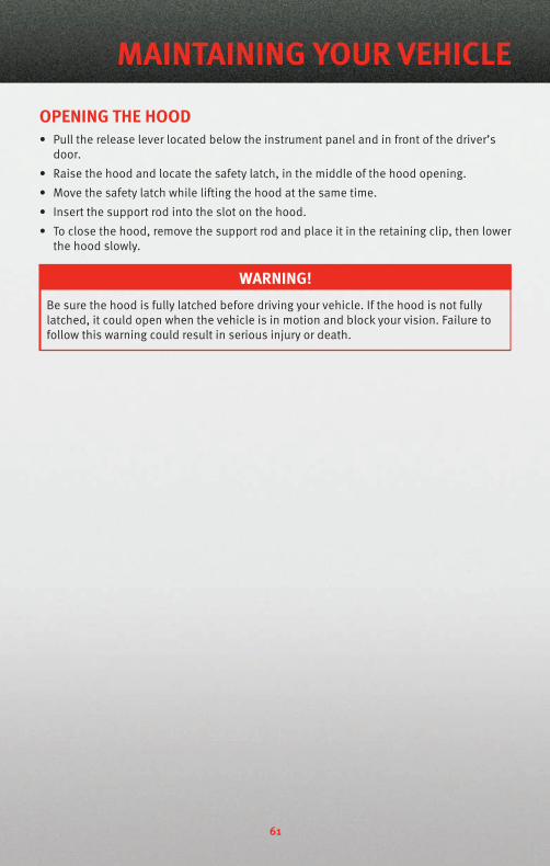
OPENING THE HOOD• Pull the release lever located below the instrument panel and in front of the driver’s
door.
• Raise the hood and locate the safety latch, in the middle of the hood opening.
• Move the safety latch while lifting the hood at the same time.
• Insert the support rod into the slot on the hood.
• To close the hood, remove the support rod and place it in the retaining clip, then lowerthe hood slowly.
WARNING!Be sure the hood is fully latched before driving your vehicle. If the hood is not fullylatched, it could open when the vehicle is in motion and block your vision. Failure tofollow this warning could result in serious injury or death.
61
MAINTAINING YOUR VEHICLE

ENG
INE
COM
PART
MEN
T2.
4LEn
gine
62
MAINTAINING YOUR VEHICLE
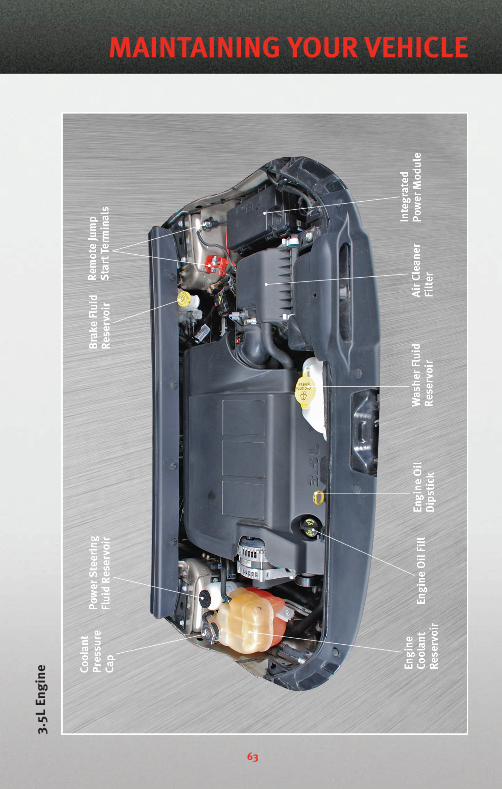
3.5L
Engi
ne
63
MAINTAINING YOUR VEHICLE

FLUIDS AND CAPACITIESComponent Fluid, Lubricant, or
Genuine PartCapacities
Engine Coolant - 2.4LEngine and Single orDual-Zone Climate ControlSystem.
MOPAR® Antifreeze/Coolant Five Year/100,000 Mile FormulaHOAT (Hybrid OrganicAdditive Technology) orequivalent.
7.9 Quarts (7.5 Liters)Includes heater andcoolant recovery bottlefilled to MAX level.
Engine Coolant - 2.4LEngine and Three-ZoneClimate Control System.
MOPAR® Antifreeze/Coolant Five Year/100,000 Mile FormulaHOAT (Hybrid OrganicAdditive Technology) orequivalent.
9.8 Quarts (9.3 Liters)Includes heater andcoolant recovery bottlefilled to MAX level.
Engine Coolant - 3.5LEngine.and Single orDual-Zone Climate ControlSystem.
MOPAR® Antifreeze/Coolant Five Year/100,000 Mile FormulaHOAT (Hybrid OrganicAdditive Technology) orequivalent.
9.8 Quarts (9.3 Liters)Includes heater andcoolant recovery bottlefilled to MAX level.
Engine Coolant - 3.5LEngine and Three-ZoneClimate Control System.
MOPAR® Antifreeze/Coolant Five Year/100,000 Mile FormulaHOAT (Hybrid OrganicAdditive Technology) orequivalent.
12 Quarts (11.4 Liters)Includes heater andcoolant recovery bottlefilled to MAX level.
Engine Oil with Filter 2.4LEngine
API Certified SAE 5W-20engine oil, meeting therequirements of ChryslerMaterial StandardMS-6395. Refer to theengine oil fill cap for correctSAE grade.
4.5 Quarts (4.26 Liters)
Engine Oil with Filter 3.5LEngine
API Certified SAE 10W-30engine oil, meetingChrysler Material StandardMS-6395. Refer to yourengine oil filler cap forcorrect SAE grade.
5.5 Quarts (5.2 Liters)
Fuel Selection 3.5L - FrontWheel Drive (FWD) Models.
87 Octane acceptable –89 Octane recommended.
20.5 Gallons (77.6 Liters)
Fuel Selection 3.5L - AllWheel Drive (AWD) Models.
87 Octane acceptable –89 Octane recommended.
21 Gallons (79.8 Liters)
Fuel Selection 2.4L PZEV(Partial Zero EmissionsVehicle) - Front Wheel Drive(FWD) Models.
87 Octane 18.5 Gallons (70 Liters)
MAINTAINING YOUR VEHICLE
64
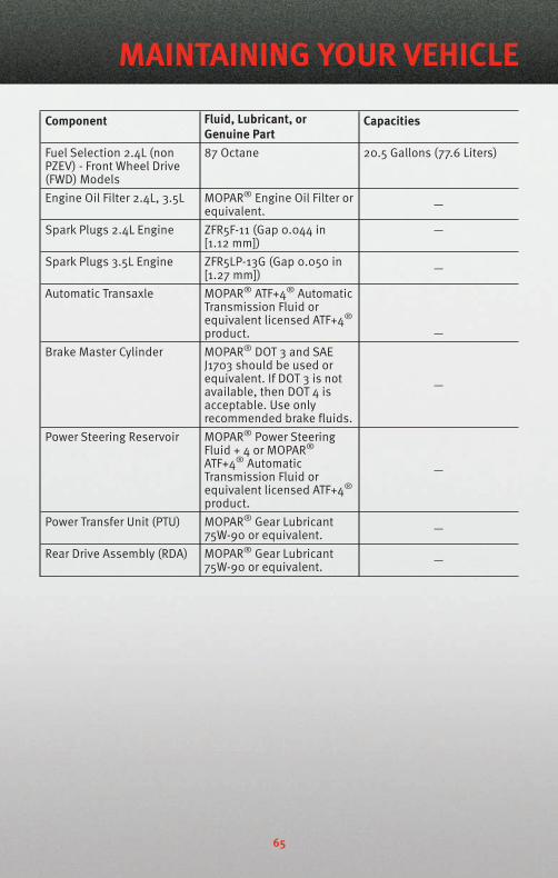
Component Fluid, Lubricant, orGenuine Part
Capacities
Fuel Selection 2.4L (nonPZEV) - Front Wheel Drive(FWD) Models
87 Octane 20.5 Gallons (77.6 Liters)
Engine Oil Filter 2.4L, 3.5L MOPAR® Engine Oil Filter orequivalent. —
Spark Plugs 2.4L Engine ZFR5F-11 (Gap 0.044 in[1.12 mm])
—
Spark Plugs 3.5L Engine ZFR5LP-13G (Gap 0.050 in[1.27 mm]) —
Automatic Transaxle MOPAR® ATF+4® AutomaticTransmission Fluid orequivalent licensed ATF+4®
product. —Brake Master Cylinder MOPAR® DOT 3 and SAE
J1703 should be used orequivalent. If DOT 3 is notavailable, then DOT 4 isacceptable. Use onlyrecommended brake fluids.
—
Power Steering Reservoir MOPAR® Power SteeringFluid + 4 or MOPAR®
ATF+4® AutomaticTransmission Fluid orequivalent licensed ATF+4®
product.
—
Power Transfer Unit (PTU) MOPAR® Gear Lubricant75W-90 or equivalent. —
Rear Drive Assembly (RDA) MOPAR® Gear Lubricant75W-90 or equivalent. —
65
MAINTAINING YOUR VEHICLE
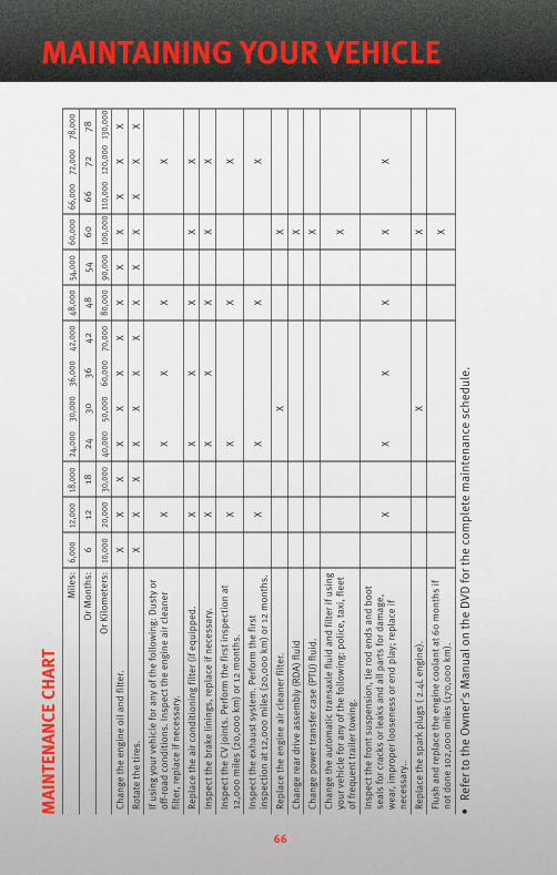
MAI
NTEN
ANCE
CHAR
TM
iles:
6,00
012
,000
18,0
0024
,000
30,0
0036
,000
42,0
0048
,000
54,0
0060
,000
66,0
0072
,000
78,0
00
OrM
onth
s:6
1218
2430
3642
4854
6066
7278
OrK
ilom
eter
s:10
,000
20,0
0030
,000
40,0
0050
,000
60,0
0070
,000
80,0
0090
,000
100,
000
110,
000
120,
000
130,
000
Chan
geth
een
gine
oila
ndfil
ter.
XX
XX
XX
XX
XX
XX
X
Rota
teth
etir
es.
XX
XX
XX
XX
XX
XX
X
Ifus
ing
your
vehi
cle
fora
nyof
the
follo
win
g:D
usty
orof
f-roa
dco
nditi
ons.
Insp
ectt
heen
gine
airc
lean
erfil
ter,
repl
ace
ifne
cess
ary.
XX
XX
X
Repl
ace
the
airc
ondi
tioni
ngfil
ter(
ifeq
uipp
ed.
XX
XX
XX
Insp
ectt
hebr
ake
linin
gs,r
epla
ceif
nece
ssar
y.X
XX
XX
X
Insp
ectt
heCV
join
ts.P
erfo
rmth
efir
stin
spec
tion
at12
,000
mile
s(2
0,00
0km
)or1
2m
onth
s.X
XX
X
Insp
ectt
heex
haus
tsys
tem
.Per
form
the
first
insp
ectio
nat
12,0
00m
iles
(20,
000
km)o
r12
mon
ths.
XX
XX
Repl
ace
the
engi
neai
rcle
aner
filte
r.X
X
Chan
gere
ardr
ive
asse
mbl
y(R
DA)
fluid
X
Chan
gepo
wer
tran
sfer
case
(PTU
)flu
id.
X
Chan
geth
eau
tom
atic
tran
saxl
eflu
idan
dfil
teri
fusi
ngyo
urve
hicl
efo
rany
ofth
efo
llow
ing:
polic
e,ta
xi,f
leet
offr
eque
nttr
aile
rtow
ing.
X
Insp
ectt
hefr
onts
uspe
nsio
n,tie
rod
ends
and
boot
seal
sfo
rcra
cks
orle
aks
and
allp
arts
ford
amag
e,w
ear,
impr
oper
loos
enes
sor
end
play
;rep
lace
ifne
cess
ary.
.
XX
XX
XX
Repl
ace
the
spar
kpl
ugs
(2.4
Len
gine
).X
X
Flus
han
dre
plac
eth
een
gine
cool
anta
t60
mon
ths
ifno
tdon
e10
2,00
0m
iles
(170
,000
km).
X
•Re
fert
oth
eO
wne
r'sM
anua
lon
the
DVD
fort
heco
mpl
ete
mai
nten
ance
sche
dule
.
66
MAINTAINING YOUR VEHICLE

Maintenance RecordOdometer Date Signature, Authorized Service Center
6,000 Miles(10,000 km) or6 Months
12,000 Miles(20,000 km) or12 Months
18,000 Miles(30,000 km) or18 Months
24,000 Miles(40,000 km) or24 Months
30,000 Miles(50,000 km) or30 Months
36,000 Miles(60,000 km) or36 Months
42,000 Miles(70,000 km) or42 Months
48,000 Miles(80,000 km) or48 Months
54,000 Miles(90,000 km) or54 Months
60,000 Miles(100,000 km)or 60 Months
66,000 Miles(110,000 km)or 66 Months
72,000 Miles(120,000 km)or 72 Months
78,000 Miles(130,000 km)or 78 Months
67
MAINTAINING YOUR VEHICLE

FUSES
MAINTAINING YOUR VEHICLE
68
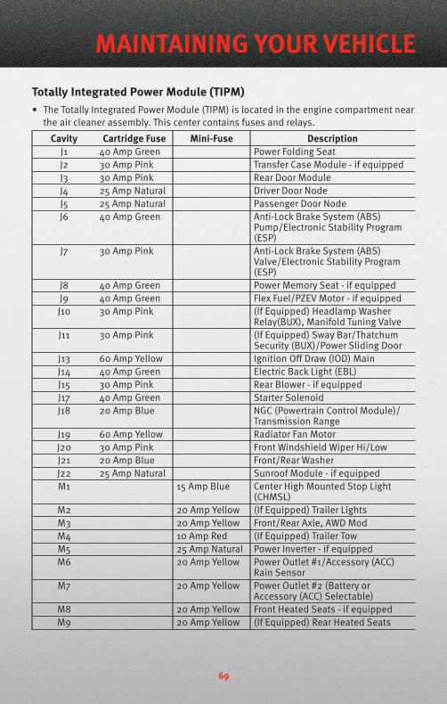
Totally Integrated Power Module (TIPM)• The Totally Integrated Power Module (TIPM) is located in the engine compartment near
the air cleaner assembly. This center contains fuses and relays.
Cavity Cartridge Fuse Mini-Fuse DescriptionJ1 40 Amp Green Power Folding SeatJ2 30 Amp Pink Transfer Case Module - if equippedJ3 30 Amp Pink Rear Door ModuleJ4 25 Amp Natural Driver Door NodeJ5 25 Amp Natural Passenger Door NodeJ6 40 Amp Green Anti-Lock Brake System (ABS)
Pump/Electronic Stability Program(ESP)
J7 30 Amp Pink Anti-Lock Brake System (ABS)Valve/Electronic Stability Program(ESP)
J8 40 Amp Green Power Memory Seat - if equippedJ9 40 Amp Green Flex Fuel/PZEV Motor - if equippedJ10 30 Amp Pink (If Equipped) Headlamp Washer
Relay(BUX), Manifold Tuning ValveJ11 30 Amp Pink (If Equipped) Sway Bar/Thatchum
Security (BUX)/Power Sliding DoorJ13 60 Amp Yellow Ignition Off Draw (IOD) MainJ14 40 Amp Green Electric Back Light (EBL)J15 30 Amp Pink Rear Blower - if equippedJ17 40 Amp Green Starter SolenoidJ18 20 Amp Blue NGC (Powertrain Control Module)/
Transmission RangeJ19 60 Amp Yellow Radiator Fan MotorJ20 30 Amp Pink Front Windshield Wiper Hi/LowJ21 20 Amp Blue Front/Rear WasherJ22 25 Amp Natural Sunroof Module - if equippedM1 15 Amp Blue Center High Mounted Stop Light
(CHMSL)M2 20 Amp Yellow (If Equipped) Trailer LightsM3 20 Amp Yellow Front/Rear Axle, AWD ModM4 10 Amp Red (If Equipped) Trailer TowM5 25 Amp Natural Power Inverter - if equippedM6 20 Amp Yellow Power Outlet #1/Accessory (ACC)
Rain SensorM7 20 Amp Yellow Power Outlet #2 (Battery or
Accessory (ACC) Selectable)M8 20 Amp Yellow Front Heated Seats - if equippedM9 20 Amp Yellow (If Equipped) Rear Heated Seats
69
MAINTAINING YOUR VEHICLE

Cavity Cartridge Fuse Mini-Fuse DescriptionM10 15 Amp Blue Vanity Lamps/Hands-Free Module
(HFM) - if equipped, Remote Display- if equipped, Satellite Digital AudioReceiver (SDARS) - if equipped,Universal Garage Door Opener(UGDO) - if equipped, Vanity Light,Video Entertainment System (VES)™- if equipped
M11 10 Amp Red Automatic Temperature Control(ATC) - if equipped, Underhood Light
M12 30 Amp Green Radio, Amplifier (AMP)M13 20 Amp Yellow Cabin Compartment Node (CCN),
Multifunction Switch/Siren Module,ITM
M14 20 Amp Yellow (If Equipped) Trailer Tow (BUX)M15 20 Amp Yellow Auto Dim Rearview Mirror - if
equipped, Infrared Sensor (IR) - ifequipped, Multifunction Switch, TirePressure Monitor System (TPMS) - ifequipped, Transfer Case Module - ifequipped,
M16 10 Amp Red Occupant Restraint Controller(ORC)/Occupant ClassificationModule (OCM)
M17 15 Amp Blue Left Park/Side Marker/Running/TailLights, License Lights
M18 15 Amp Blue Right Park/Side Marker/Running/Tail Lights
M19 25 Amp Natural Auto Shut Down (ASD) #1 and #2M20 15 Amp Blue Electronic Vehicle Information
Center (EVIC) - if equipped, InteriorLighting, Steering Wheel Switches -if equipped, Switch Bank
M21 20 Amp Yellow Auto Shut Down (ASD) #3M22 10 Amp Red Right HornM23 10 Amp Red Left HornM24 25 Amp Natural Rear WiperM25 20 Amp Yellow Fuel Pump/Diesel Lift PumpM26 10 Amp Red Power MIRRORS Switch/Drivers
Window SwitchM27 10 Amp Red Steering Column Lock, Wireless
Ignition Node (WIN)/PEMM28 10 Amp Red NGC (Powertrain Control
Module)/Transmission Feed (Batt)M29 10 Amp Red Occupant Classification Module
(OCM)
MAINTAINING YOUR VEHICLE
70

Cavity Cartridge Fuse Mini-Fuse DescriptionM30 15 Amp Blue Rear Wiper Module Module/Power
Folding Mirror, J1962 Diag FeedM31 20 Amp Yellow Back-Up LightsM32 10 Amp Red Occupant Restraint Controller (ORC)M33 10 Amp Red NGC (Powertrain Control Module)
Battery Feed/TCMM34 10 Amp Red Power Assist Module, HVAC Module,
Headlamp Washers, CompassModule - if equipped, Flashlight - ifequipped, RAD Fan Diesel
M35 10 Amp Red Heated Mirrors - if equippedM36 20 Amp Yellow Power Outlet #3 (Batt)M37 10 Amp Red Anti-Lock Brake System (ABS),
Electronic Stability Program (ESP),STOP LIGHT Switch
M38 25 Amp Natural Lock/Unlock Motors
TIRE PRESSURES• Check the inflation pressure of each tire, including the spare tire, at least monthly and
inflate to the recommended pressure for your vehicle.
• The tire pressures recommended for your vehicle are found on the “Tire and LoadingInformation” label located on the driver’s side door opening.
NOTE: Refer to the Owner's Manual on the DVD for more information on the life of tires.
WARNING!Overloading of your tires is dangerous. Overloading can cause tire failure, affectvehicle handling, and increase your stopping distance. Use tires of the recommendedload capacity for your vehicle. Never overload them.
WARNING!Improperly inflated tires are dangerous and can cause accidents. Under-inflation isthe leading cause of tire failure and may result in severe cracking, componentseparation, or “blow out”. Over-inflation reduces a tire’s ability to cushion shock.Objects on the road and chuck holes can cause damage that results in tire failure.Unequal tire pressures can cause steering problems. You could lose control of yourvehicle. Over-inflated or under-inflated tires can affect vehicle handling and can failsuddenly, resulting in loss of vehicle control.
71
MAINTAINING YOUR VEHICLE
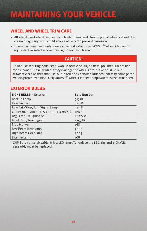
WHEEL AND WHEEL TRIM CARE• All wheels and wheel trim, especially aluminum and chrome plated wheels should be
cleaned regularly with a mild soap and water to prevent corrosion.
• To remove heavy soil and/or excessive brake dust, use MOPAR® Wheel Cleaner orequivalent or select a nonabrasive, non-acidic cleaner.
CAUTION!Do not use scouring pads, steel wool, a bristle brush, or metal polishes. Do not useoven cleaner. These products may damage the wheels protective finish. Avoidautomatic car washes that use acidic solutions or harsh brushes that may damage thewheels protective finish. Only MOPAR® Wheel Cleaner or equivalent is recommended.
EXTERIOR BULBSLIGHT BULBS – Exterior Bulb NumberBackup Lamp 3157KRear Tail Lamp 3157KRear Tail/Stop/Turn Signal Lamp 3157KCenter High-Mounted Stop Lamp (CHMSL) LED *Fog Lamp - If Equipped PSX24WFront Park/Turn Signal 3757AKSide Marker 168Low Beam Headlamp 9006High Beam Headlamp 9005License Lamp 168
* CHMSL is not serviceable. It is a LED lamp. To replace the LED, the entire CHMSLassembly must be replaced.
MAINTAINING YOUR VEHICLE
72
CHRYSLER GROUP LLCCUSTOMER CENTERP.O. Box 21–8004
Auburn Hills, MI 48321–8004
Phone: 1–800–992–1997
CHRYSLER CANADA INC.CUSTOMER CENTERP.O. Box 1621
Windsor, Ontario N9A 4H6
Phone: 1–800–465–2001
ASSISTANCE FOR THEHEARING IMPAIRED• To assist customers who have hearing
difficulties, the manufacturer hasinstalled special TDD(Telecommunication Devices for theDeaf ) equipment at its customercenter. Any hearing or speechimpaired customer, who has access toa TDD or a conventional teletypewriter(TTY) in the United States, cancommunicate with the manufacturerby dialing 1–800–380–CHRY.Canadian residents with hearingdifficulties that require assistance canuse the special needs relay serviceoffered by Bell Canada. For TTYteletypewriter users, dial 711 and forVoice callers, dial 1–800–855–0511 toconnect with a Bell Relay Serviceoperator.
WARNING!Engine exhaust, some of itsconstituents, and certain vehiclecomponents contain, or emit,chemicals known to the State ofCalifornia to cause cancer and birthdefects, or other reproductive harm.In addition, certain fluids containedin vehicles and certain products ofcomponent wear contain, or emit,chemicals known to the State ofCalifornia to cause cancer and birthdefects, or other reproductive harm.
PUBLICATIONS ORDERING• If you are the first registered retail
owner of your vehicle, you may obtaina free printed copy of the Owner'sManual, Warranty Booklet or RadioManuals on your DVD by calling1–800–992–1997 (U.S.) or1–800–387–1143 (Canada) or bycontacting your dealer.
• Replacement User Guides or DVDs or,if you prefer, a printed copy of theOwner's Manual, Warranty Booklet orRadio Manuals may be purchased byvisiting www.techauthority.com or bycalling 1–800–890–4038 (U.S.) or1–800–387–1143 (Canada). Visa,Master Card, American Express andDiscover orders are accepted. If youprefer mailing your order, please callthe above numbers for an order form.
NOTE: A street address is requiredwhen ordering manuals (no P.O. Boxes).
73
CONSUMER ASSISTANCE
REPORTING SAFETY DEFECTSIN THE 50 UNITED STATESAND WASHINGTON, D.C.• If you believe that your vehicle has a
defect that could cause a crash orcause injury or death, you shouldimmediately inform the NationalHighway Traffic Safety Administration(NHTSA) in addition to notifying themanufacturer.
• If NHTSA receives similar complaints,it may open an investigation, and if itfinds that a safety defect exists in agroup of vehicles, it may order a recalland remedy campaign. However,NHTSA cannot become involved inindividual problems between you,your authorized dealer, and themanufacturer.
• To contact NHTSA, you may either callthe Auto Safety Hotline toll free at1–888–327–4236 (TTY: 1–800–424–9153), or go to http://www.safercar.gov; or write to:Administrator, NHTSA, 1200 NewJersey Avenue, SE., West Building,Washington, D.C. 20590. You can alsoobtain other information about motorvehicle safety fromhttp://www.safercar.gov.
In Canada• If you believe that your vehicle has a
safety defect, you should contact theCustomer Service Departmentimmediately. Canadian customerswho wish to report a safety defect tothe Canadian government shouldwrite to: Transport Canada, MotorVehicle Defect Investigations andRecalls, 2780 Sheffield Road, Ottawa,Ontario K1B 3V9.
TIRE WARRANTYTire Limited Warranty AndAdjustment Policy• When a tire is removed from service
due to a covered warranty conditionunder a tire manufacturer’s “LimitedWarranty Program”, you may beeligible for a free tire replacement or acomparable new tire on a “proratedbasis”.
• Certain conditions, such as irregularwear or tire damage due to roadhazards, collision, improper inflation,intentional alteration, and misuse,are excluded from the LimitedWarranty Program. The LimitedWarranty Program expires when yourtires either wear to a specified treaddepth, and/or after a period of timefrom the date of purchase, as statedin the Tire Warranty on the DVD.
NOTE: Refer to the Tire Warranty onthe DVD for specific information relatingto the manufacturer's limited warrantyfor the tires installed on your vehicle.The DVD can play on any computer orDVD player. If you have any questionsregarding the limited tire warrantycoverage, contact your local Chryslerdealer or your local authorized tiredealer. If you cannot access the DVDand would like a paper copy of thelimited warranty for the tires installedon your vehicle, call 1-800-922-1997(U.S.) or 1-800-387-1143 (Canada) or askyour Chrysler dealer.
CONSUMER ASSISTANCE
74
Disclaimer:• THE TIRE MANUFACTURER’S LIMITED
WARRANTY PROGRAM, THE DETAILSOF WHICH CAN BE FOUND, ON THEOWNERS MANUAL DVD, THE TIREMANUFACTURER’S WEBSITE OR ATANY AUTHORIZED SERVICE CENTERARE IN LIEU OF ALL OTHER REMEDIESOR WARRANTIES, EXPRESS ORIMPLIED, ARISING BY LAW OROTHERWISE, INCLUDING FITNESS FORA PARTICULAR PURPOSE ORMERCHANTABILITY. THE TIREMANUFACTURER EXPRESSLYDISCLAIMS LIABILITY FOR INDIRECT,SPECIAL, INCIDENTAL ORCONSEQUENTIAL DAMAGES, LOSTPROFIT, LOSS OF BUSINESS, LOSS OFGOODWILL, LOSS OF REPUTATION,PUNITIVE OR ANY OTHER DAMAGE,COST OR LOSS OF ANY KIND. SOMESTATES AND PROVINCES DO NOTALLOW THE EXCLUSION OR LIMITATIONOF INCIDENTAL OR CONSEQUENTIALDAMAGES, SO THE ABOVE LIMITATIONOR EXCLUSION MAY NOT APPLY TOYOU.
WARNING!NOTE: Refer to the Owner's Manual onthe DVD for complete warninginformation that could preventaccidents, injuries and even deaths.
WARNING!Death, serious injury and/or propertydamage may result from:• Tire failure due to impact damage
and/or improper maintenance.
(Continued)
WARNING! (Continued)
• Tires should be inspected regularlyby a qualified technician for signsof damage, such as punctures,impacts, underinflation oroverloading.
• Progressive air loss may result frompunctures, cuts, curbing, impactsor partial bead unseating.
Some fitment causes for air loss are:• Incomplete bead seating.• Bead tearing caused by a machine
tool due to insufficient lubricationor improper adjustment.
• Leaking valve core or rubber valvecomponents (these should bereplaced when problems aredetected and whenever tires arereplaced).
• Tire failure due to improper repairs.• See Rubber Manufacturer's
Association (RMA) establishedrepair procedures at www.rma.orgfor information on proper repairprocedures. Never perform atemporary repair or use an innertube as a substitute for a properrepair. Only qualified personsshould repair tires.
• Explosion of tire/rim assembly dueto improper mounting.
• Only specially trained personsshould mount tires.
• Failure to mount tires on approvedrims.
• Failure to deflate single or dualassemblies completely beforedemounting.
75
CONSUMER ASSISTANCE
Using Lift Kits• Use of lift kits with some vehicle/tire
combinations can cause instability orloss of control. When changing tiresizes, always consult an installer foroptimum rim width and carefullycheck vehicle/tire clearances.
Check Your Tires For Damage• Frequent (at least monthly) inspection
of your tires for signs of damage,uneven tread wear and their generalcondition is important for safety.Impacts, penetrations, cracks, knots,bulges or air loss always require tireremoval and expert inspection.
Tire Service Life• The service life of a tire is dependent
upon varying factors including, butnot limited to, your driving style, tirepressure and distance driven.
WARNING!Tires and the spare tire should bereplaced after six years, regardless ofthe remaining tread. Failure to followthis warning can result in sudden tirefailure. You could lose control andhave an accident resulting in seriousinjury or death.
• Keep dismounted tires in a cool, dryplace with as little exposure to thelight as possible.
• Protect tires from contact with oil,grease, and gasoline.
NOTE: All tire warranties are made bythe tire manufacturer. Tires are notcovered under your Chrysler New VehicleLimited Warranty.
CONSUMER ASSISTANCE
76
MOPAR® ACCESSORIES• The following highlights just some of the authentic Dodge Accessories by MOPAR®
that have been engineered to customize your Dodge Journey.
• To see the full line of accessories stop by your Dodge dealer or visit MOPAR.com.
CHROME:• Bodyside Moldings • Fuel Filler Door • Exhaust Tips
EXTERIOR:• Side Window Air
Deflectors• Sunroof Air Deflector • Front Air Deflector
• Hitch Receiver • Fog Lights • Molded Splash Guards
INTERIOR:• Premium Carpet Floor
Mats• Door Sill Guards • Molded Cargo Tray
• Slush Mats
ELECTRONICS:• Portable Navigation
Systems• uconnect™ hands-free
Communication withiPod® Integration
• Sirius Satellite Radio
• iPod® Adapter • Remote Start • DVD Rear Seat Video™
CARRIERS:• Hitch-mount Bike Carrier • Roof Mount Bike Carrier • Roof Box Cargo Carrier• Roof Mount Ski and
Snowboard Carrier• Roof Mount Water Sports
Carrier• Roof Mount Canoe Carrier
iPod® is a registered trademark of Apple Inc.
77
MOPAR ACCESSORIES

NOTES
78

79
NOTES

NOTES
80

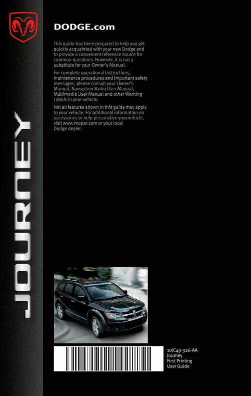
DODGE.com
This guide has been prepared to help you get quickly acquainted with your new Dodge and to provide a convenient reference source for common questions. However, it is not a substitute for your Owner’s Manual.
For complete operational instructions, maintenance procedures and important safety messages, please consult your Owner’s Manual, Navigation Radio User Manual, Multimedia User Manual and other Warning Labels in your vehicle.
Not all features shown in this guide may apply to your vehicle. For additional information on accessories to help personalize your vehicle, visit www.mopar.com or your local Dodge dealer.
10JC49-926-AAJourneyFirst PrintingUser Guide