
2009 09 ISBN 978-0-8269-4360-6 - Talon...
16
AMERICAN TECHNICAL PUBLISHERS, INC. HOMEWOOD, ILLINOIS 60430-4600 2009 09 ISBN 978-0-8269-4360-6
-
Upload
nguyentuyen -
Category
Documents
-
view
223 -
download
2
Transcript of 2009 09 ISBN 978-0-8269-4360-6 - Talon...

AMERICAN TECHNICAL PUBLISHERS, INC.HOMEWOOD, ILLINOIS 60430-4600
2009
09
ISBN 978-0-8269-4360-6

1
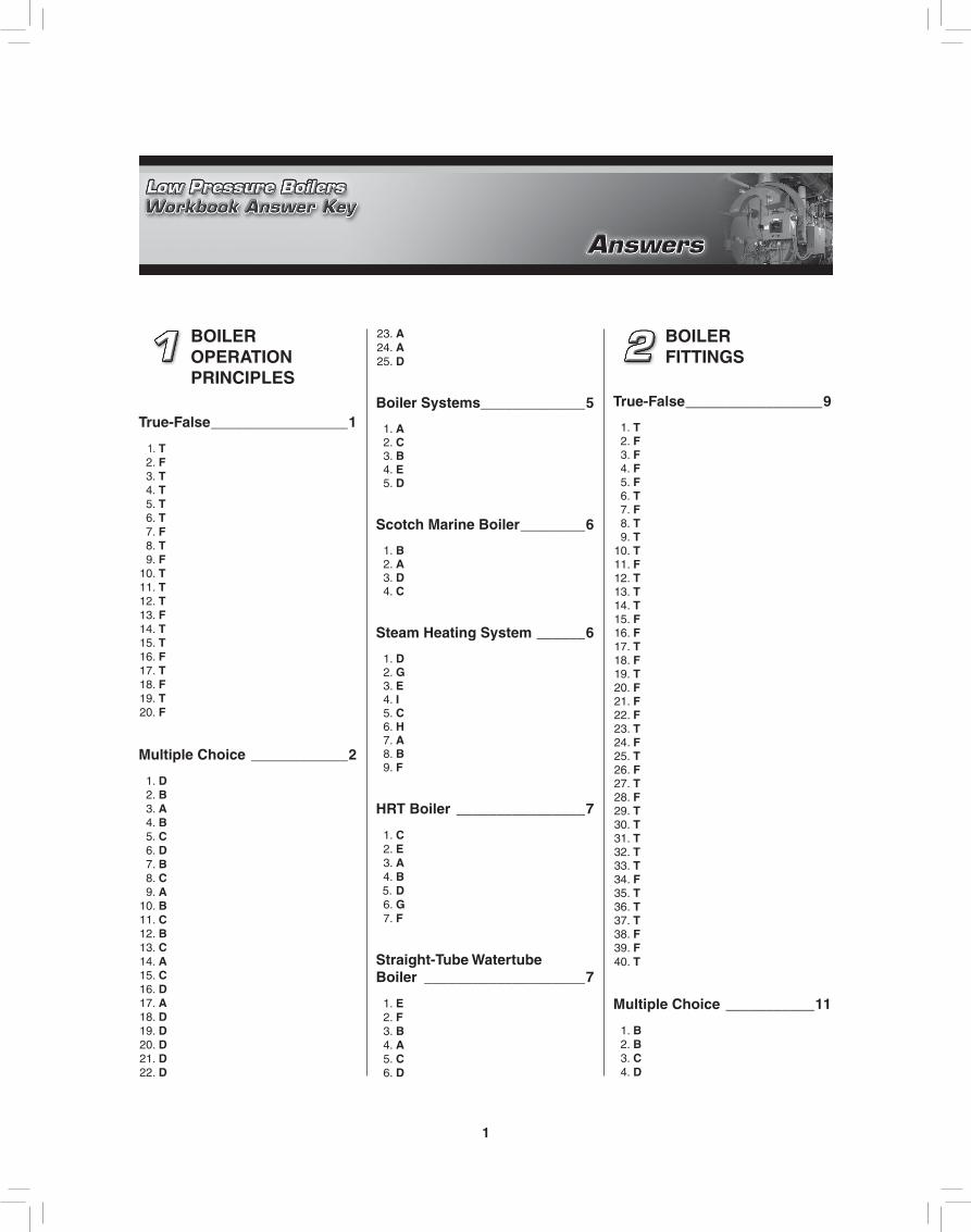
BOILER OPERATION PRINCIPLES
True-False _________________1
1. T 2. F 3. T 4. T 5. T 6. T 7. F 8. T 9. F 10. T 11. T 12. T 13. F 14. T 15. T 16. F 17. T 18. F 19. T 20. F
Multiple Choice ____________2
1. D 2. B 3. A 4. B 5. C 6. D 7. B 8. C 9. A 10. B 11. C 12. B 13. C 14. A 15. C 16. D 17. A 18. D 19. D 20. D 21. D 22. D
23. A 24. A 25. D
Boiler Systems _____________5
1. A 2. C 3. B 4. E 5. D
Scotch Marine Boiler ________6
1. B 2. A 3. D 4. C
Steam Heating System ______6
1. D 2. G 3. E 4. I 5. C 6. H 7. A 8. B 9. F
HRT Boiler ________________7
1. C 2. E 3. A 4. B 5. D 6. G 7. F
Straight-Tube Watertube Boiler ____________________7
1. E 2. F 3. B 4. A 5. C 6. D
BOILER FITTINGS
True-False _________________9
1. T 2. F 3. F 4. F 5. F 6. T 7. F 8. T 9. T 10. T 11. F 12. T 13. T 14. T 15. F 16. F 17. T 18. F 19. T 20. F 21. F 22. F 23. T 24. F 25. T 26. F 27. T 28. F 29. T 30. T 31. T 32. T 33. T 34. F 35. T 36. T 37. T 38. F 39. F 40. T
Multiple Choice ___________11
1. B 2. B 3. C 4. D

2 LOW PRESSURE BOILERS WORKBOOK ANSWER KEY
5. D 6. D 7. B 8. C 9. C 10. B 11. D 12. A 13. C 14. B 15. D 16. A 17. A 18. D 19. B 20. D 21. C 22. C 23. C 24. D 25. B 26. C 27. B 28. D 29. C 30. D 31. D 32. A 33. B 34. C 35. A 36. A 37. C 38. A 39. B 40. A
Safety Valve ______________16
1. F 2. E 3. A 4. B 5. H 6. C 7. D 8. G
Safety Valve Huddling Chamber ________17
1. D 2. E 3. A 4. F 5. C 6. B
Steam Pressure Gauge Operation ________________17
1. C 2. E 3. D 4. G
5. F 6. A 7. B
Water Column and Gauge Glass _____________17
1. C 2. D 3. A 4. I 5. G 6. F 7. H 8. B 9. E
Bottom Blowdown Valve ____18
1. D 2. A 3. B 4. C
FEEDWATER SYSTEM
True-False ________________19
1. T 2. T 3. F 4. T 5. T 6. T 7. T 8. T 9. T 10. F 11. F 12. T 13. T 14. F 15. T 16. T 17. F 18. T 19. T 20. T
Multiple Choice ___________20
1. C 2. B 3. D 4. D 5. B 6. B 7. D 8. C
9. D 10. C 11. B 12. B 13. B 14. B 15. C 16. A 17. C 18. D 19. A 20. B
Testing Low Water Fuel Cutoff _______________22
1. D 2. B 3. A 4. E 5. C
Feedwater System _________23
1. C 2. E 3. J 4. I 5. F 6. G 7. L 8. N 9. A 10. B 11. M 12. D 13. H 14. K
Makeup Water System ______23
1. H 2. A 3. F 4. G 5. J 6. E 7. B 8. C 9. I 10. D
Feedwater Control _________24
1. A 2. B 3. F 4. E 5. C 6. I 7. D 8. H 9. G

Answers 3
Feedwater Line ___________24
1. B 2. D 3. E 4. A 5. C
Vacuum Pump ____________24
1. E 2. F 3. B 4. G 5. A 6. D 7. C
Centrifugal Water Pump ____25
1. B 2. F 3. C 4. E 5. A 6. D
Low Water Fuel Cutoff Parts ______________25
1. B 2. E 3. A 4. F 5. C 6. D
Low Water Fuel Cutoff Operation ________________25
1. B 2. F 3. C 4. D 5. A 6. E
STEAM SYSTEM
True-False ________________27
1. T 2. F 3. T 4. T 5. T 6. F 7. T
8. F 9. T 10. F
Multiple Choice ___________27
1. B 2. C 3. D 4. A 5. C 6. D 7. A 8. D 9. B 10. A 11. D 12. B 13. A 14. D 15. C 16. B 17. A 18. B 19. C 20. B
Main Steam Stop Valve _____30
1. D 2. B 3. E 4. A 5. G 6. I 7. F 8. H 9. C
Steam Trap Operation ______31
1. A 2. B 3. D 4. C 5. C 6. A 7. D 8. B 9. D 10. B 11. C 12. A 13. C 14. A 15. B 16. D
Steam Trap _______________31
1. C 2. A 3. D 4. B
Steam Trap Location _______32
1. F 2. E 3. H 4. A 5. K 6. G 7. J 8. D 9. I 10. B 11. C
Steam Trap Testing Devices ___________33
1. C 2. D 3. B 4. A 5. E
Testing Steam Traps _______34
1. B 2. C 3. A
FUEL SYSTEM
True-False ________________37
1. T 2. T 3. T 4. T 5. T 6. F 7. T 8. T 9. F 10. T 11. T 12. T 13. F 14. T 15. T 16. T 17. T 18. F 19. T 20. F 21. F 22. T 23. T 24. T 25. F 26. T 27. T 28. T
4 LOW PRESSURE BOILERS WORKBOOK ANSWER KEY
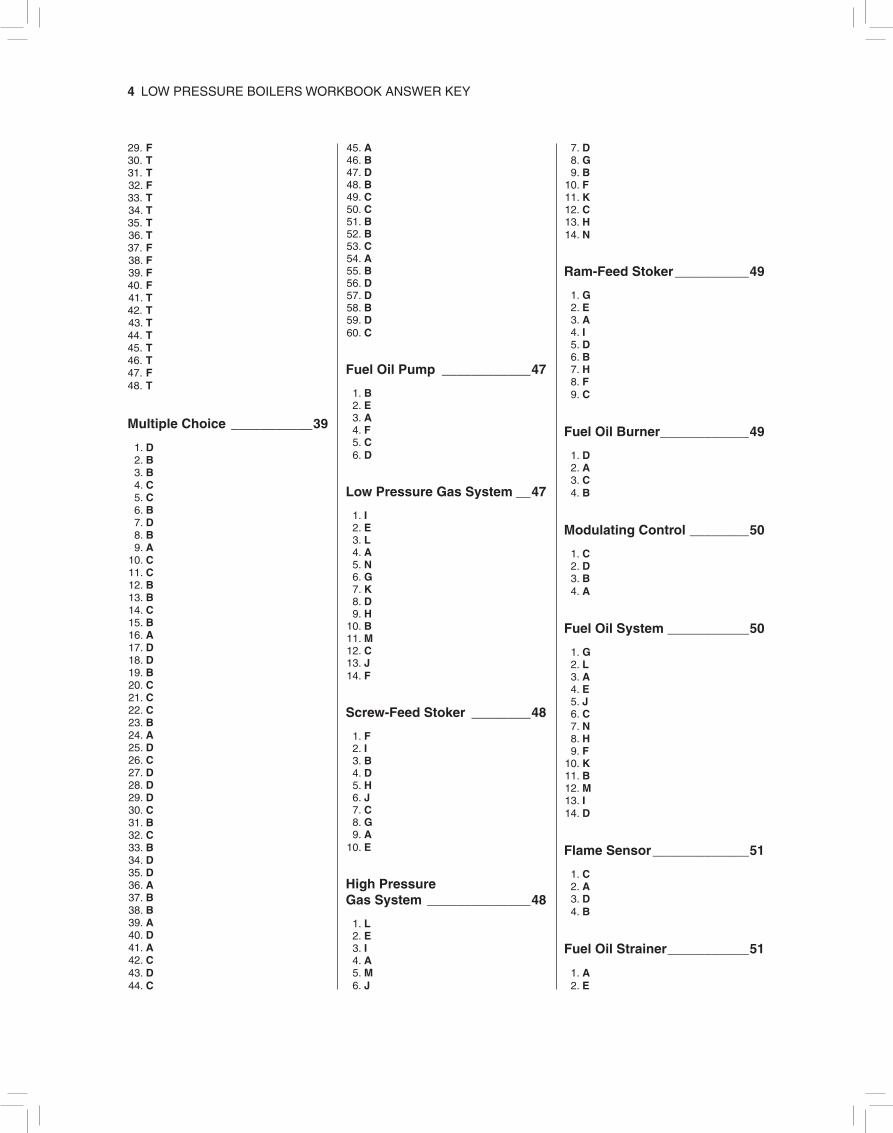
29. F 30. T 31. T 32. F 33. T 34. T 35. T 36. T 37. F 38. F 39. F 40. F 41. T 42. T 43. T 44. T 45. T 46. T 47. F 48. T
Multiple Choice ___________39
1. D 2. B 3. B 4. C 5. C 6. B 7. D 8. B 9. A 10. C 11. C 12. B 13. B 14. C 15. B 16. A 17. D 18. D 19. B 20. C 21. C 22. C 23. B 24. A 25. D 26. C 27. D 28. D 29. D 30. C 31. B 32. C 33. B 34. D 35. D 36. A 37. B 38. B 39. A 40. D 41. A 42. C 43. D 44. C
45. A 46. B 47. D 48. B 49. C 50. C 51. B 52. B 53. C 54. A 55. B 56. D 57. D 58. B 59. D 60. C
Fuel Oil Pump ____________47
1. B 2. E 3. A 4. F 5. C 6. D
Low Pressure Gas System __47
1. I 2. E 3. L 4. A 5. N 6. G 7. K 8. D 9. H 10. B 11. M 12. C 13. J 14. F
Screw-Feed Stoker ________48
1. F 2. I 3. B 4. D 5. H 6. J 7. C 8. G 9. A 10. E
High Pressure Gas System ______________48
1. L 2. E 3. I 4. A 5. M 6. J
7. D 8. G 9. B 10. F 11. K 12. C 13. H 14. N
Ram-Feed Stoker __________49
1. G 2. E 3. A 4. I 5. D 6. B 7. H 8. F 9. C
Fuel Oil Burner ____________49
1. D 2. A 3. C 4. B
Modulating Control ________50
1. C 2. D 3. B 4. A
Fuel Oil System ___________50
1. G 2. L 3. A 4. E 5. J 6. C 7. N 8. H 9. F 10. K 11. B 12. M 13. I 14. D
Flame Sensor _____________51
1. C 2. A 3. D 4. B
Fuel Oil Strainer ___________51
1. A 2. E
Answers 5
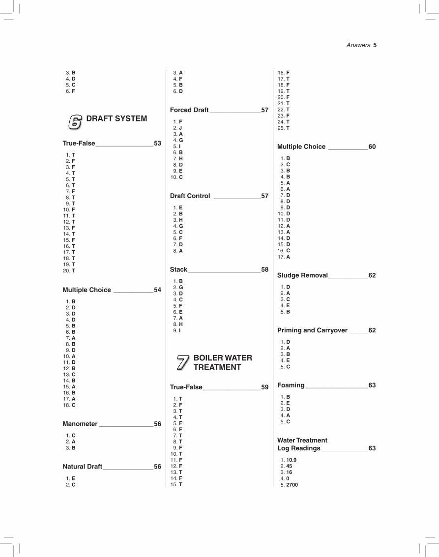
3. B 4. D 5. C 6. F
DRAFT SYSTEM
True-False ________________53
1. T 2. F 3. F 4. T 5. T 6. T 7. F 8. T 9. T 10. F 11. T 12. T 13. F 14. T 15. F 16. T 17. T 18. T 19. T 20. T
Multiple Choice ___________54
1. B 2. D 3. D 4. D 5. B 6. B 7. A 8. B 9. D 10. A 11. D 12. B 13. C 14. B 15. A 16. B 17. A 18. C
Manometer _______________56
1. C 2. A 3. B
Natural Draft ______________56
1. E 2. C
3. A 4. F 5. B 6. D
Forced Draft ______________57
1. F 2. J 3. A 4. G 5. I 6. B 7. H 8. D 9. E 10. C
Draft Control _____________57
1. E 2. B 3. H 4. G 5. C 6. F 7. D 8. A
Stack ____________________58
1. B 2. G 3. D 4. C 5. F 6. E 7. A 8. H 9. I
BOILER WATER TREATMENT
True-False ________________59
1. T 2. F 3. T 4. T 5. F 6. F 7. T 8. T 9. F 10. T 11. F 12. F 13. T 14. F 15. T
16. F 17. T 18. F 19. T 20. F 21. T 22. T 23. F 24. T 25. T
Multiple Choice ___________60
1. B 2. C 3. B 4. B 5. A 6. A 7. D 8. D 9. D 10. D 11. D 12. A 13. A 14. D 15. D 16. C 17. A
Sludge Removal ___________62
1. D 2. A 3. C 4. E 5. B
Priming and Carryover _____62
1. D 2. A 3. B 4. E 5. C
Foaming _________________63
1. B 2. E 3. D 4. A 5. C
Water Treatment Log Readings _____________63
1. 10.9 2. 45 3. 16 4. 0 5. 2700

6 LOW PRESSURE BOILERS WORKBOOK ANSWER KEY
Bypass Feeder ____________64
1. E 2. B 3. D 4. A 5. C 6. F
BOILER OPERATION PROCEDURES
True-False ________________65
1. T 2. T 3. T 4. T 5. F 6. T 7. F 8. F 9. F 10. T 11. F 12. T 13. T 14. T 15. F 16. F 17. T 18. F 19. T 20. F 21. F 22. T 23. T 24. F 25. T 26. T 27. F 28. F 29. T 30. T 31. F 32. T 33. F 34. T 35. F 36. T 37. T 38. F 39. F 40. T 41. F 42. T 43. F 44. F 45. F
Multiple Choice ___________67
1. D 2. C
3. B 4. C 5. B 6. B 7. D 8. D 9. A 10. C 11. D 12. C 13. A 14. B 15. D 16. C 17. C 18. A 19. C 20. B 21. A 22. A 23. D 24. B 25. D 26. D 27. A 28. A 29. C 30. A 31. A 32. A 33. A 34. D 35. D 36. C 37. B 38. B 39. B 40. A
HOT WATER HEATING SYSTEMS
True-False ________________73
1. T 2. F 3. F 4. T 5. F 6. F 7. F 8. T 9. F 10. T 11. T 12. F 13. F 14. T 15. T 16. T 17. F 18. T 19. F
20. T 21. T 22. F 23. F 24. T 25. F 26. T 27. T 28. F 29. T 30. T
Multiple Choice ___________74
1. A 2. B 3. D 4. C 5. C 6. B 7. C 8. D 9. D 10. D 11. B 12. A 13. C 14. C 15. B 16. C 17. C 18. D 19. B 20. D 21. D 22. D 23. C 24. B 25. C
Natural Circulation Hot Water Heating System ___________78
1. G 2. A 3. H 4. C 5. F 6. E 7. B 8. D
Aquastat _________________78
1. B 2. G 3. I 4. D 5. F 6. H 7. C 8. E 9. A
Answers 7
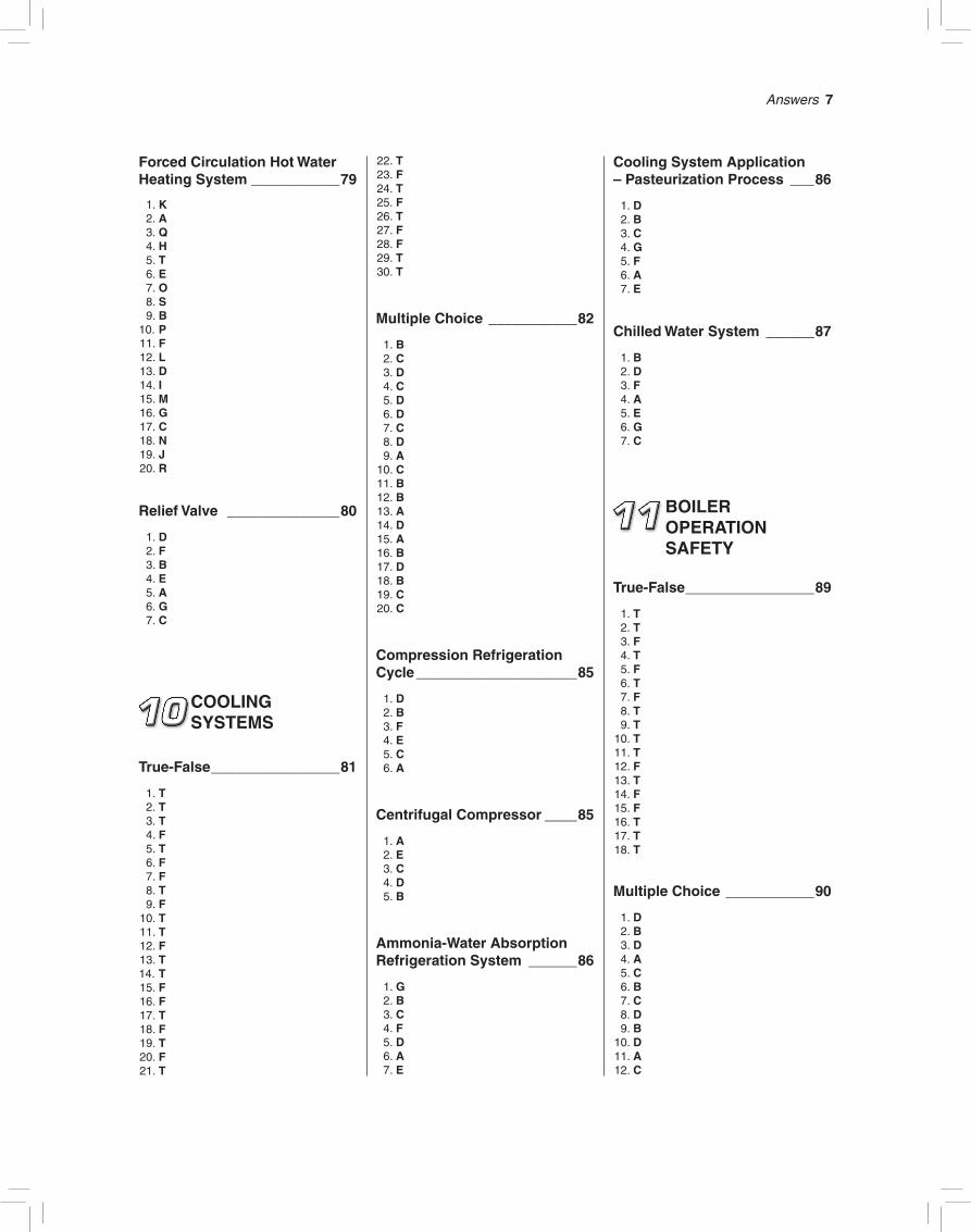
Forced Circulation Hot Water Heating System ___________79
1. K 2. A 3. Q 4. H 5. T 6. E 7. O 8. S 9. B 10. P 11. F 12. L 13. D 14. I 15. M 16. G 17. C 18. N 19. J 20. R
Relief Valve ______________80
1. D 2. F 3. B 4. E 5. A 6. G 7. C
COOLING SYSTEMS
True-False ________________81
1. T 2. T 3. T 4. F 5. T 6. F 7. F 8. T 9. F 10. T 11. T 12. F 13. T 14. T 15. F 16. F 17. T 18. F 19. T 20. F 21. T
22. T 23. F 24. T 25. F 26. T 27. F 28. F 29. T 30. T
Multiple Choice ___________82
1. B 2. C 3. D 4. C 5. D 6. D 7. C 8. D 9. A 10. C 11. B 12. B 13. A 14. D 15. A 16. B 17. D 18. B 19. C 20. C
Compression Refrigeration Cycle ____________________85
1. D 2. B 3. F 4. E 5. C 6. A
Centrifugal Compressor ____85
1. A 2. E 3. C 4. D 5. B
Ammonia-Water Absorption Refrigeration System ______86
1. G 2. B 3. C 4. F 5. D 6. A 7. E
Cooling System Application – Pasteurization Process ___86
1. D 2. B 3. C 4. G 5. F 6. A 7. E
Chilled Water System ______87
1. B 2. D 3. F 4. A 5. E 6. G 7. C
BOILER OPERATION SAFETY
True-False ________________89
1. T 2. T 3. F 4. T 5. F 6. T 7. F 8. T 9. T 10. T 11. T 12. F 13. T 14. F 15. F 16. T 17. T 18. T
Multiple Choice ___________90
1. D 2. B 3. D 4. A 5. C 6. B 7. C 8. D 9. B 10. D 11. A 12. C

8 LOW PRESSURE BOILERS WORKBOOK ANSWER KEY
13. D 14. A 15. D 16. B
Hazardous Material Container Labeling – RTK Labeling ____92
1. D 2. F 3. A 4. E 5. B 6. C
BOILER OPERATOR LICENSING
Sample Licensing Exam 1 True-False ________________93
1. T 2. F 3. T 4. F 5. F 6. T 7. T 8. F 9. T 10. T 11. T
Multiple Choice ___________94
1. A 2. B 3. B 4. B 5. D 6. C 7. C 8. A 9. A 10. C 11. D 12. C 13. A 14. B 15. B 16. A 17. C 18. D 19. C 20. C 21. A 22. B 23. D 24. C
25. A 26. D 27. B 28. B 29. A 30. C 31. D 32. D 33. B 34. B 35. B 36. C 37. C 38. B 39. A 40. D 41. D 42. A 43. B 44. B 45. D
Sample Licensing Exam 2 True-False _______________101
1. T 2. F 3. F 4. T 5. T 6. F 7. T 8. T 9. F 10. T
Multiple Choice __________101
1. C 2. D 3. B 4. C 5. C 6. A 7. B 8. B 9. A 10. A 11. A 12. C 13. D 14. D 15. C 16. B 17. D 18. B 19. A 20. A 21. A 22. B 23. A 24. C 25. C 26. D 27. A 28. D
29. B 30. D 31. A32. B33. B34. D35. B36. C37. D38. A39. D40. B41. B42. C43. A44. C45. C
Sample Licensing Exam 3 True-False _______________109
1. F 2. T 3. T 4. T 5. F 6. T 7. T 8. F 9. T 10. T 11. T
Multiple Choice __________109
1. D 2. A 3. D 4. B 5. D 6. C 7. A 8. A 9. B 10. B 11. B 12. C 13. B 14. C 15. A 16. D 17. C 18. A 19. A 20. A 21. D 22. B 23. B 24. D 25. A 26. A 27. A 28. B 29. B 30. B
Answers 9
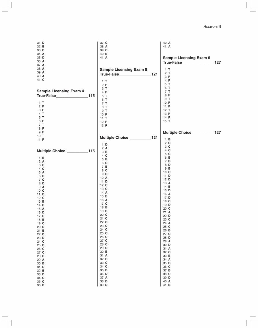
31. D 32. B 33. D 34. A 35. D 36. A 37. A 38. A 39. A 40. A 41. C
Sample Licensing Exam 4 True-False _______________115
1. T 2. F 3. F 4. T 5. T 6. F 7. T 8. F 9. F 10. T 11. F
Multiple Choice __________115
1. B 2. A 3. C 4. C 5. A 6. B 7. C 8. D 9. A 10. C 11. D 12. C 13. B 14. D 15. A 16. D 17. C 18. B 19. C 20. D 21. B 22. D 23. D 24. C 25. D 26. C 27. C 28. B 29. A 30. B 31. D 32. B 33. D 34. C 35. C 36. B
37. C 38. A 39. C 40. B 41. A
Sample Licensing Exam 5 True-False _______________121
1. T 2. F 3. T 4. F 5. T 6. T 7. T 8. T 9. T 10. F 11. T 12. F 13. F
Multiple Choice __________121
1. D 2. A 3. B 4. C 5. B 6. C 7. B 8. C 9. C 10. A 11. D 12. C 13. C 14. A 15. B 16. A 17. C 18. B 19. B 20. C 21. C 22. C 23. C 24. C 25. C 26. C 27. C 28. C 29. D 30. B 31. A 32. C 33. C 34. C 35. B 36. D 37. A 38. D 39. D
40. A 41. A
Sample Licensing Exam 6 True-False _______________127
1. T 2. T 3. F 4. F 5. T 6. T 7. T 8. F 9. T 10. F 11. F 12. T 13. F 14. F 15. T
Multiple Choice __________127
1. B 2. C 3. C 4. C 5. C 6. B 7. B 8. D 9. B 10. C 11. D 12. D 13. A 14. B 15. D 16. A 17. D 18. C 19. D 20. C 21. A 22. D 23. C 24. A 25. C 26. B 27. C 28. D 29. A 30. D 31. A 32. C 33. B 34. A 35. B 36. C 37. B 38. C 39. D 40. A 41. B

10 LOW PRESSURE BOILERS WORKBOOK ANSWER KEY
Sample Licensing Exam 7 Essay __________________133
1. Report to work 10 to 15 minutes early. Check the water level on all the boilers on the line by blowing down the gauge glass, water column, and low water fuel cutoff. NOTE: (1) The burners should be firing when the low water fuel cutoff is blown down. This not only removes any sludge and sediment from the lines, but also shuts off the burner to ensure its proper opera-tion. (2) When blowing down the gauge glass, the water should leave the gauge glass quickly and return quickly when the gauge glass blowdown valve is closed. This indicates that the lines are clean.
2. Steam coming out of the bottom try cock is an indication of low water condition in the boiler. The burner must be secured, the boiler taken off-line and cooled slowly, and the chief engineer and/or boiler in-spector must be notified so the boiler can be inspected for any overheating of the heating surface. NOTE: Never add water to a boiler that has overheated before checking for possible damage.
3. Water coming out of the top try cock is an indication of a high water level condition. The boiler must be given a bottom blow-down to prevent carryover and possible water hammer. The operator should then determine the cause of the high water level condition.
4. The different ways of getting water to the boiler are the vacuum pump, feedwater pump, automatic city water makeup feeder, and hand-operated city water makeup valve.
5. The pressure control is sensitive to pres-sure and controls the boiler operating range. It starts and stops the burner on steam pressure demand.
6. Safety valves are tested by hand or by pressure. The ASME code recommends that safety valves be tested at least once a month by raising the boiler pressure and causing the safety valve(s) to pop open. When testing a safety valve by hand there should be at least 5 psi of pressure before lifting the test lever. The hand test lever is lifted to fully open the safety valve and is released to allow the safety valve to snap shut. NOTE: Check with local inspectors or the mechanical inspection bureau regard-ing the proper testing of safety valves.
7. According to Section VI of the ASME code, safety valves on low pressure boilers should be tested by hand once every 30 days the boiler is in operation.The ASME code also recommends the
testing of safety valves under pressure once a year, preferably before the start of the heating season. In addition to the ASME code, safety valves should be tested according to recommendations of the local boiler inspector.
8. The function of the low water fuel cutoff is to shut the burner off to protect the boiler heating surface from becoming over-heated due to low water in the boiler.
9. The two methods of testing the low water fuel cutoff are by hand or by an evapo-ration test. When testing the burner by hand, the blowdown valve on the low wa-ter fuel cutoff is opened and steam and water rushing out cause the float in the low water fuel cutoff to drop, resulting in the burner shutting off. When performing an evaporation test, the vacuum pump, feedwater pump (if the boiler has one), and the automatic city water makeup feeder must be secured. The water level will drop in the boiler and the float in the low water fuel cutoff will fall slowly, shutting the burner off. NOTE: When the burner shuts off, there must always be water still visible in the gauge glass.
10. The maximum allowable working pres-sure (MAWP) for a low pressure steam boiler is 15 psi. A safety valve must pop (open) whenever pressure exceeds the safety valve setting to prevent the boiler from exceeding its MAWP. Anytime a safety valve pops, the boiler operator must determine the cause and take cor-rective action.
11. The safety valves on low pressure steam boilers are set to pop open at 15 psi.
12. Purging a furnace is the part of the firing cycle when the burner motor fan blows air into the furnace to remove any mixture of gases or fumes of a combus-tible nature that might cause a furnace explosion. The furnace is always purged before the burner lights off (prepurge) and starts again after the burner shuts off (postpurge).
13. The most important valve on the boiler is the safety valve. The safety valve prevents the boiler from exceeding its MAWP. If the safety valve exceeds its MAWP, a boiler explosion could result.
14. The boiler should be given a bottom blowdown whenever tests of the boiler water indicate high chemical concentra-tion or high total dissolved solids. The boiler should also be blown down when a high water level develops.
15. The flame scanner can be tested in two ways. One method is to remove the scanner from its sighting tube and
cover it with your hand, which should shut off the burner. The second method is to secure the fuel going to the burner to simulate a fuel failure, which should cause the scanner to shut the burner off on safety lockout.
16. There are two methods of determining the water level in the boiler. One method is to blow down the gauge glass and watch the action of the water leaving and returning to the glass. The second method is to use the three try cocks and observe what comes out of the top try cock, middle try cock, and bottom try cock when they are opened. With an NOWL the top try cock should discharge steam, the middle try cock should discharge a mixture of wa-ter and steam, and the bottom try cock should discharge water.
17. Smoke is the result of incomplete com-bustion. For example, in fuel oil-burning plants, smoke could be caused by cold fuel oil, poor atomization, insufficient pri-mary and secondary air, a dirty burner, or fuel oil impinging on the brickwork.
18. The two types of draft used in boilers are natural draft and mechanical draft. Mechanical draft can be further clas-sified as forced draft, induced draft, or combination forced and induced draft.
19. The check valve on the feedwater line pre-vents water from leaving the boiler when the vacuum pump or boiler feedwater pump stops. A check valve controls the flow of feedwater in one direction only.
20. The stop valve is located on the feedwa-ter line as close to the shell of the boiler as practical between the boiler and the check valve. The stop valve is required in the event the check valve malfunctions (sticks open or closed). The stop valve could then be secured (closed) and the check valve repaired without having to dump the boiler.
21. The safety valve popping and steam pressure of 30 psi would indicate mal-function of the safety valve(s). The pro-cedure to follow would be to: (1) Secure the burner. (2) Allow steam pressure to drop to approximately 15 psi. (3) Use the safety valve test lever to test the safety valve(s) by hand. (4) If the safety valve(s) pop open and reset at the proper blow-back, raise the steam pressure to see if the safety valve(s) popped by pressure. (5) If the safety valve(s) popped by pres-sure, determine why the pressure control did not function properly. NOTE: The boiler in question should not be left unat-tended. A new boiler should be warmed up and cut in on the line if there is one available. If this is the only boiler in the

Answers 11
plant, it must be attended 24 hours a day until it can be taken off-line and given a complete safety check.
22. Perfect combustion is the burning of all the fuel using the theoretical amount of air. Perfect combustion can only be achieved in a laboratory setting. Com-plete combustion is the burning of all the fuel using the minimum amount of excess air. Incomplete combustion is when all the fuel is not burned, resulting in soot and smoke.
23. Furnace explosions are caused by a buildup of highly combustible gases or fumes that ignite when exposed to a spark, pilot flame, or radiant brickwork. In addition, furnace explosions can result from improper purging of the furnace after a flame failure, a leaking fuel valve allowing fuel to enter the furnace, or the operator bypassing safety interlocks in order to light the burner quicker after a fuel interruption.
24. Before a boiler can be inspected, it must be taken off-line. Once a boiler is off-line, the following safety checks must be made: (1) The main steam stop valve(s) (some boilers have two) must be closed and tagged out. To tag out a valve means to mark it so it will not be opened by mistake. Some plants attach a sign to the valve wheel that reads “Danger! Person-nel in boiler–do not open.” (2) The boiler vent or top try cock should be checked to see that it is open. This ensures there is no vacuum inside. (3) The feedwater line to the boiler must be closed and tagged out. If there is an automatic city water makeup valve, it must be secured also.
25. A gauge glass should be blown down once a shift or whenever the operator questions the level of water in the boiler.
26. In a forced circulation system, the system is closed to the atmosphere and water is forced (circulated) through the heat-ing system using circulating pumps. In a natural circulation system, the system is open to the atmosphere. It works on the principle that water when heated increases in volume (expands) and becomes less dense. The warmer water rises and cold, denser water flows back into the bottom of the boiler.
27. In order to do a hydrostatic test on a boiler, the boiler must be completely filled with water. To perform a hydrostatic test, the following operations must be carried out: (1) If the water column has a whistle valve, it must be removed and plugged. (2) The main steam stop valve must be closed. (3) The safety valve(s) must be removed and blank flanges
installed, or the safety valves must be gagged. (A gag is a clamp that prevents the valve from popping open without damaging the valve.) (4) The boiler vent must remain open until water comes out and then is closed. (5) Pressure on the boiler is brought up to 1½ times the MAWP. (The pressure must be under control so that it does not exceed this pressure by more than 10 pounds.)
28. NOWL stands for the normal operating water level. In a steam boiler the NOWL is approximately one-third to one-half a gauge glass.
29. MAWP stands for the maximum allow-able working pressure of a boiler. The MAWP of a given boiler is determined by the ASME code.
30. Carryover can be caused by (1) carrying too high a water level, (2) high boiler wa-ter surface tension, and (3) opening the boiler main steam stop valve too quickly.
31. Natural draft is created by the height of the chimney and the difference in tem-perature of the gases of combustion in the chimney and the air outside the chimney. Mechanical draft is caused by a fan.
32. A feedwater pump becomes steam-bound when the temperature of the water in the open feedwater heater gets too hot and water in the suction line going to the feedwater pump flashes into steam.
33. A fast gauge is a pressure gauge that reads more steam pressure than is actually pres-ent in the boiler. A slow gauge is a pressure gauge that reads less steam pressure than is actually present in the boiler.
34. Foaming is caused by impurities in the boiler water. A surface blowdown is used to remove impurities in the boiler water that cause foaming.
35. An open gate valve offers no restriction to the flow of the material passing through it. A gate valve must always be fully open or fully closed. A globe valve has mate-rial flowing under a valve seat and has some resistance to flow. A globe valve is used for throttling (varying the rate of flow) service by partly opening or closing the valve.
36. In a watertube boiler, water passes through tubes that are surrounded by gases of combustion. In a firetube boiler, gases of combustion pass through tubes that are surrounded by water.
37. The water column must be located at the NOWL so that the lowest visible part of the gauge glass is a minumum of 1″ above
the highest heating surface. The top line to the water column is connected to the highest part of the steam side of the boiler. The bottom line to the water column is connected approximately 6″ below the center line of a firetube boiler.
38. The best time to give a boiler a bottom blowdown is when the boiler is at its lightest load. This allows sludge and sediment to fall to the bottom.
39. The function of a boiler vent is to: (1) vent air from the boiler when filling it with water, (2) vent air from the boiler when warming up prior to cutting in on the line, and (3) prevent a vacuum from forming in the boiler when taking the boiler off-line.
40. The high and low fire of the burner are controlled by the modulating pressure control through the modulating motor.
41. An os&y valve is open when its stem is visible in the up position.
42. The purpose of the vacuum pump is to help return the condensate back to the vacuum tank. At the vacuum tank, air is vented to the atmosphere, and water is pumped directly back to the boiler or a condensate return tank.
43. The automatic city water makeup feeder is a safety device that ensures that the boiler will have water if the vacuum pump fails or condensate is lost in the system. For maximum protection and safety, the automatic city water makeup feeder should be blown down daily to ensure its proper operation in an emergency.
44. The steam traps most commonly used are the nonreturn type. This type in-cludes thermostatic, inverted bucket, and float thermostatic.
45. The two methods most commonly used to test the proper function of steam traps are strap-on thermometers and temperature-indicating crayons.
46. Fuel oil strainers should be cleaned daily and whenever unusually high suction readings occur when fuel oil is at its proper temperature.
47. Two types of fuel oil burners commonly used in low pressure plants are rotary cup burners and air atomizing burners.
48. The advantage of using a combination burner is plant flexibility. The opera-tor can burn the fuel that is cheapest, change from one fuel to another if prob-lems occur, and keep the plant operating if there is a shortage of a fuel.
49. Air used in the combustion process is broadly classified as primary, secondary,
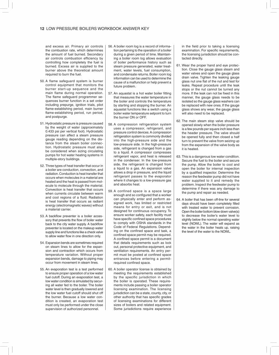
12 LOW PRESSURE BOILERS WORKBOOK ANSWER KEY
and excess air. Primary air controls the combustion rate, which determines the amount of fuel burned. Secondary air controls combustion efficiency by controlling how completely the fuel is burned. Excess air is supplied to the burner above the theoretical amount required to burn the fuel.
50. A flame safeguard system is burner control equipment that monitors the burner star t-up sequence and the main flame during normal operation. The flame safeguard programmer se-quences burner function in a set order including prepurge, ignition trials, pilot flame-establishing period, main burner flame-establishing period, run period, and postpurge.
51. Hydrostatic pressure is pressure caused by the weight of water (approximately 0.433 psi per vertical foot). Hydrostatic pressure can affect a steam pressure gauge reading depending on the dis-tance from the steam boiler connec-tion. Hydrostatic pressure must also be considered when sizing circulating pumps for hot water heating systems in multiple-story buildings.
52. Three types of heat transfer that occur in a boiler are conduction, convection, and radiation. Conduction is heat transfer that occurs when molecules in a material are heated and the heat is passed from mol-ecule to molecule through the material. Convection is heat transfer that occurs when currents circulate between warm and cool regions of a fluid. Radiation is heat transfer that occurs as radiant energy (electromagnetic waves) without a material carrier.
53. A backflow preventer is a boiler acces-sory that prevents the flow of boiler water back to the city water supply. A backflow preventer is located on the makeup water supply line and functions like a check valve to allow water flow in one direction only.
54. Expansion bends are sometimes required on steam lines to allow for the expan-sion and contraction which occurs from temperature variation. Without proper expansion bends, damage to piping may occur from movement in steam lines.
55. An evaporation test is a test performed to ensure proper operation of a low water fuel cutoff. During an evaporation test, a low water condition is simulated by secur-ing all water fed to the boiler. The boiler water level is then gradually lowered and the low water fuel cutoff should shut off the burner. Because a low water con-dition is created, an evaporation test must only be performed under the close supervision of authorized personnel.
56. A boiler room log is a record of informa-tion pertaining to the operation of a boiler during a given period of time. Maintain-ing a boiler room log allows evaluation of boiler performance history such as steam pressure generated, water treat-ment, water levels, fuel consumption, and condensate returns. Boiler room log information can be used to determine the cause of a malfunction or help prevent a future problem.
57. An aquastat is a hot water boiler fitting that measures the water temperature in the boiler and controls the temperature by starting and stopping the burner. An aquastat functions like a switch using a boiler water temperature setpoint to turn the burner ON or OFF.
58. A compression refrigeration system uses a compressor, refrigerant, and pressure control devices. A compression refrigeration system is commonly divided into the high-pressure side and the low-pressure side. In the high-pressure side, refrigerant is changed from a gas to a liquid. A compressor compresses refrigerant vapor, and heat is released in the condenser. In the low-pressure side, the refrigerant is changed from a liquid to a gas. An expansion valve allows a drop in pressure, and the liquid refrigerant passes to the evaporator where it changes to a low-pressure gas and absorbs heat.
59. A confined space is a space large enough and so configured that a worker can physically enter and perform as-signed work, has limited or restricted means for entry or exit, and is not designed for continuous occupancy. To ensure worker safety, each facility must have specific confined space procedures to comply with OSHA standards in the Code of Federal Regulations. Depend-ing on the confined space and task, a confined space permit may be required. A confined space permit is a document that details requirements such as lock out, personal protective equipment, and ventilation requirements. An entry per-mit must be posted at confined space entrances before entering a permit- required confined space.
60. A boiler operator license is obtained by meeting the requirements established by the specific jurisdiction in which the boiler is operated. These require-ments include passing a boiler operator licensing examination. The licensing jurisdiction can be a state, county, city, or other authority that has specific grades of licensing examinations for different sizes of boilers and related equipment. Some jurisdictions require experience
in the field prior to taking a licensing examination. For specific requirements, the licensing jurisdiction should be con-tacted directly.
61. Wear the proper hand and eye protec-tion. Close the gauge glass steam and water valves and open the gauge glass drain valve. Tighten the leaking gauge glass nut one flat of the nut and test for leaks. Repeat procedure until the leak stops or the nut cannot be turned any more. If the leak can not be fixed in this manner, the gauge glass needs to be isolated so the gauge glass washers can be replaced with new ones. If the gauge glass shows any wear, the gauge glass will also need to be replaced.
62. The main steam stop valve should be opened slowly when the boiler pressure is a few pounds per square inch less than the header pressure. The valve should be opened fully and then closed a half turn to prevent the valve from seizing up from the expansion of the valve body as it is heated.
63. This is a dangerous low water condition. Secure the fuel to the boiler and secure the pump. Allow the boiler to cool and open the boiler for internal inspection by a qualified inspector. Determine the reason the feedwater pump did not have water supplied to it and remedy the problem. Inspect the feedwater pump to determine if there was any damage to the pump and repair as needed.
64. A boiler that has been off-line for several days should have been completely filled with treated water to prevent corrosion. Open the boiler bottom blow down valve(s) to decrease the boiler’s water level to slightly below the normal operating water level (NOWL). The water will expand as the water in the boiler heats up, raising the level of the water to the NOWL.


9 0 0 0 0
9 7 8 0 8 2 6 9 4 3 6 0 6
ISBN 978-0-8269-4360-6


![[XLS] · Web view1 2 41 500000 8269 0 8269 2 2 40 1240 0 1240 3 2 13 827 0 827 4 2 73 3721 0 3721 14057 5 5 49 500000 8269 0 8269 6 5 47 1240 0 1240 7 5 19 827 0 827 8 5 21 827 0](https://static.fdocuments.net/doc/165x107/5ad91cce7f8b9a991b8e2e67/xls-view1-2-41-500000-8269-0-8269-2-2-40-1240-0-1240-3-2-13-827-0-827-4-2-73-3721.jpg)