![[MS-RDPERP]: Remote Desktop Protocol: Remote Programs ...... · 2 / 97 [MS-RDPERP] - v20160714 Remote Desktop Protocol: Remote Programs Virtual Channel Extension Copyright © 2016](https://static.fdocuments.net/doc/165x107/6001d70f342c8842893c15ae/ms-rdperp-remote-desktop-protocol-remote-programs-2-97-ms-rdperp.jpg)
2008 Series Remote Protocol Manual - Fresenius Medical Care
24
P/N 490224 Rev. B 2008 ® Series Remote Protocol Manual
Transcript of 2008 Series Remote Protocol Manual - Fresenius Medical Care

P/N 490224 Rev. B
2008® Series Remote Protocol Manual
2 2008 Series Remote Protocol Manual P/N 490224 Rev. B
2008 Series Remote Protocol Manual
© Copyright 2013, 2016, Fresenius USA, Inc.—All Rights Reserved
This document contains proprietary information of Fresenius Medical Care Renal Therapies
Group, LLC and its affiliates (“Fresenius Medical Care”). The contents of this document may
not be disclosed to third parties, copied, or duplicated in any form, in whole or in part, without
the prior written permission of Fresenius Medical Care.
Contact Fresenius Medical Care Technical Support for available Field Service Bulletins.
The spare parts manual for the 2008 and other information may be found on our web site at
www.fmcna.com.

2008 Series Remote Protocol Manual P/N 490224 Rev. B 3
CONTENTS
About this manual………………………………………………………………………………….4
Definitions………………………………………………………………………………………….5
CHAPTER 1
Communications Protocol Overview………………………………………………………………6
CHAPTER 2
Data Format………………………………………………………………………………………..8
CHAPTER 3
Standard Communication Protocol……………………………………………………………….12
CHAPTER 4
Checksum Communication Protocol……………………………………………………………..13
APPENDIX A
Commands………………………………………………………………………………………..18
APPENDIX B
Group Codes……………………………………………………………………………………...19
APPENDIX C
Field Codes……………………………………………………………………………………….20

About this manual…
4 2008 Series Remote Protocol Manual P/N 490224 Rev. B
About this manual…
The purpose of the 2008 Series Remote Protocol Manual is to provide a guideline for software
developers to generate external applications to be used in conjunction with the 2008T, 2008K,
2008K2, or the 2008K@Home
™ hemodialysis machine. It is not intended as a guide for
performing hemodialysis, a medical treatment that should only be performed under the
supervision of a licensed physician.
This document should be used in conjunction with the appropriate operator’s manual, depending
on the model of hemodialysis machine:
- 2008T Hemodialysis Machine Operator’s Manual – P/N 490122
- 2008K Hemodialysis Machine Operator’s Manual – P/N 490042
- 2008K2 Hemodialysis Machine Operator’s Manual – P/N 490136
- 2008K@Home User’s Guide – P/N 490180
This manual is organized to guide a software application developer through the syntax expected
by the Remote Protocol associated with 2008 Series hemodialysis machines. It begins with the
general Communications Protocol Overview, which describes the communications settings
necessary for the transmission of data. Next, the programmer is guided through the data format
that should be used when communicating with the machine. Finally, the manual leads the reader
through the two communication protocols that may be used with a 2008 series hemodialysis
machine: standard and checksum. Also included in the appendices are details about the data that
may be sent to the machine and the expected information returned by the machine.
The organization of the 2008 Series Remote Protocol is as follows:
Preface
Identifies the intended audience, and describes how the manual is organized.
Chapter 1 – Communications Protocol Overview
Introduces the operator to the machine interface communication and the framework for
communication with a 2008 Series hemodialysis machine.
Chapter 2 – Data Format
Provides instructions on the structure of the data to be transmitted to and from the
machine.
Chapter 3 – Standard Communication Protocol
Describes the standard packet structure involved in communicating with the machine.
Chapter 4 – Checksum Communication Protocol
Guides the user through the steps and structure involved in the checksum procedure.
Appendix A: Commands
Appendix B: Group Codes
Appendix C: Field Codes

Definitions
2008 Series Remote Protocol Manual P/N 490224 Rev. B 5
Definitions
Abbreviation Meaning
ASCII ASCII stands for “American Standard Code for Information Interchange”
Machine Any 2008 Series hemodialysis machine. (i.e. 2008K, 2008K2, 2008K@Home,
2008T)
RS232 RS232 stands for “Recommended Standard 232” of serial communication
Host The computer or hardware that houses the communicating application.
<SOH> ASCII control character 0x01. Start of header.
<STX> ASCII control character 0x02. Start of transmission.
<ETX> ASCII control character 0x03. End of transmission.
<ACK> ASCII control character 0x06. Positive Acknowledgement.
<NAK> ASCII control character 0x15. Negative Acknowledgement.
TMP Trans-Membrane Pressure
BTM Blood Temperature Module
BVM Blood Volume Module
UF Ultra Filtrate
SVS Sodium Variation System
Kecn Effective Conductivity Clearance
Kt/V Dialysis Treatment Adequacy
OLC Online Clearance
Questions?
For further information regarding the communication protocols related to the 2008 Series hemodialysis
machines, please contact:
Fresenius USA
4040 Nelson Ave (800) 227-2572
Concord, CA 94520 (925) 288-4218
Chapter 1 – Communications Protocol Overview
6 2008 Series Remote Protocol Manual P/N 490224 Rev. B
Chapter 1
Communications Protocol Overview
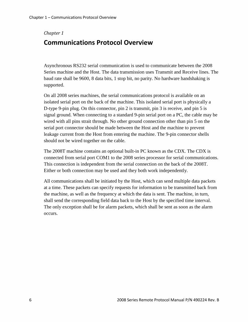
Asynchronous RS232 serial communication is used to communicate between the 2008
Series machine and the Host. The data transmission uses Transmit and Receive lines. The
baud rate shall be 9600, 8 data bits, 1 stop bit, no parity. No hardware handshaking is
supported.
On all 2008 series machines, the serial communications protocol is available on an
isolated serial port on the back of the machine. This isolated serial port is physically a
D-type 9-pin plug. On this connector, pin 2 is transmit, pin 3 is receive, and pin 5 is
signal ground. When connecting to a standard 9-pin serial port on a PC, the cable may be
wired with all pins strait through. No other ground connection other than pin 5 on the
serial port connector should be made between the Host and the machine to prevent
leakage current from the Host from entering the machine. The 9-pin connector shells
should not be wired together on the cable.
The 2008T machine contains an optional built-in PC known as the CDX. The CDX is
connected from serial port COM1 to the 2008 series processor for serial communications.
This connection is independent from the serial connection on the back of the 2008T.
Either or both connection may be used and they both work independently.
All communications shall be initiated by the Host, which can send multiple data packets
at a time. These packets can specify requests for information to be transmitted back from
the machine, as well as the frequency at which the data is sent. The machine, in turn,
shall send the corresponding field data back to the Host by the specified time interval.
The only exception shall be for alarm packets, which shall be sent as soon as the alarm
occurs.

Chapter 1 – Communications Protocol Summary
2008 Series Remote Protocol Manual P/N 490224 Rev. B 7
There are two types of communication protocols that can be used when interacting with
the 2008 Series hemodialysis machine:
Standard Protocol
This is the fundamental layer of data protocol. It involves a simple set of request
and response data packets without handshaking. (See Chapter 3)
Checksum Protocol
This is the data protocol that encapsulates the data inside. The protocol adds
header and checksum components for data security, as well as handshaking to
enhance communication. The Checksum Protocol can also be referred to as
“New Protocol” or “iCare Protocol”. (See Chapter 4)
The communication can be configured to run either protocol by entering the machine’s
Service Mode. To enter Service Mode, turn on the machine and press the [Enter] key
when prompted “Press CONFIRM For Service Mode”. After the machine boots up in
Service Mode, navigate to the Options menu and select Comm Options. On this screen,
the “New Protocol” button controls the communication type. To configure the
communication for the CDX on the 2008T hemodialysis machine, this screen also
contains a “CDX New Protocol” button. Selecting Yes enables the Checksum Protocol;
selecting No enables the Standard Protocol. After selecting the intended protocol, press
the [Enter] key to confirm the selection.

Chapter 2 – Data Format
8 2008 Series Remote Protocol Manual P/N 490224 Rev. B
Chapter 2
Data Format
A packet shall contain a single Data Section that may fall under one of three categories:
Control
Field
Acknowledgement.
Control-type Data
A Control-type data packet can only be sent from the Host to the 2008 Series
hemodialysis machine.
The data may include one or more of the following components: Commands, Group
Codes, and Interval Updates. Each component should be separated by a comma.
A Command is a 2- or 3-character string that prompts the machine to perform a
function. No data should be transmitted back from the machine in response to a
Command.
A Group Code is a 2-character string that prompts the machine to send Field
packets back to the Host that correspond with the designated group. (See
Appendix B)
An Interval Update is a 2- or 3-character string that prompts the machine to
change the frequency at which data is sent back from the machine. The default
interval is 0 seconds. The minimum interval in Standard Protocol is 10 seconds;
the minimum interval in Checksum Protocol is 11 seconds. The maximum
interval for both protocols is 600 seconds. Any value outside the range of
accepted values is defaulted to 0. When an Interval Update is successfully
transmitted, the machine’s internal interval timer resets.
When each component is received, the machine updates an internal list of controls,
adding the component to the list if it was not already called. Duplicate controls shall be
treated as if only one instance of the control is made. Invalid controls shall be ignored by
the machine. The only way to clear the list is to send a Reset Command “CX”. This
Command also resets the interval to 0 unless followed by an Interval Update.

Chapter 2 – Data Format
2008 Series Remote Protocol Manual P/N 490224 Rev. B 9
Components of a Control-type data packet shall be read from left to right. Items listed
before a Reset Command shall be cleared and replaced with the items after “CX”. Also,
in the case of multiple Interval Updates, only the rightmost integer shall be considered.
Here are some examples of valid Control-type Data Sections*:
Example 1: CX
0x43 0x58
Situation: Single Control
Result: Prompt the machine to reset communications (including the interval)
Example 2: DI,VX,013
0x44 0x49 0x2C 0x56 0x58 0x2C 0x30 0x31 0x33
Situation: Multiple Controls Result: Prompt the machine to send DI and VX group data packets (TP, DF, CD, BF;
VP, VH, VL) to the Host every 13 seconds.
Example 3: BP,CX,DI
0x42 0x50 0x2C 0x43 0x58 0x2C 0x44 0x49
Situation: Embedded CX
Result: Prompt the machine to reset communications (including the interval) and send
DI group data packets (TP, DF, CD, BF). Data will not be sent from the machine
until an interval update.
Example 4: BP,011,DI,015
0x42 0x50 0x2C 0x30 0x31 0x31 0x2C 0x44 0x49 0x2C 0x30 0x31 0x35
Situation: Multiple Interval Updates Result: Prompt the machine to send BP and DI group data packets (SY, DY, PL, MA;
TP, DF, CD, BF) to the Host every 15 seconds.
Example 5: BP,BP
0x42 0x50 0x2C 0x42 0x50
Situation: Duplicate Group Codes Result: Prompt the machine to send BP group data packets (SY,DY,PL,MA). This
will occur at the specified interval.
* Each example shows the ASCII string of the Controls. The subsequent line represents the hexadecimal
ASCII of the data.

Chapter 2 – Data Format
10 2008 Series Remote Protocol Manual P/N 490224 Rev. B
Field-type Data
A Field-type data packet can only be sent from the 2008 Series hemodialysis machine to
the Host. It shall contain information requested by previous Control-type data packets.
These packets shall be sent continuously at the specified interval until a Reset Command
is received.
This data is composed of any number of Field items. Each item is separated by a comma.
If there is no data to be transmitted under Standard Protocol, the Data Section shall
remain empty but the packet will be sent at the specified interval. Otherwise, if there is no
data to be transmitted in Checksum Protocol, the machine will not send any packet back.
Each item has two components: a 2-character Field Code and a corresponding Field
Value. Certain Field Codes are only available when running Checksum Protocol. The
format of the Field Value is dependent on the Field Code. (See Appendix C)
Here are some examples of valid Field-type Data Sections*:
Example 1: UR0600,UTT
0x55 0x52 0x30 0x36 0x30 0x30 0x2C 0x55 0x54 0x54
Situation: Host sent UF Group Code
Result: UF rate (xxxx) = 600 mL/min.
UF on (T/F) = True
Example 2: RIF,DSF,DIT,BST
0x52 0x49 0x46 0x2C 0x44 0x53 0x46 0x2C 0x44 0x49 0x54 0x2C 0x42 0x53 0x54
Situation: Host sent MS Group Code
Result: Rinse Mode (T/F) = False
Disinfect Mode (T/F) = False
Dialysis Mode (T/F) = True
Blood Sensed (T/F) = True
* Each example shows the ASCII string of the Fields. The subsequent line represents the hexadecimal
ASCII of the data. Items within the result parentheses display the Field Value data formats of their
respective Field Codes.

Chapter 2 – Data Format
2008 Series Remote Protocol Manual P/N 490224 Rev. B 11
Acknowledgment-type Data
An Acknowledgement-type data packet can be sent by either the Host or the 2008 Series
hemodialysis machine. It should be sent after receiving a Control or Field packet only in
Checksum Protocol.
This data is generated after verifying the checksum of a received Control-type or Field-
type data packet. The result of the verification dictates the appropriate acknowledgement
response.
The Data section can contain exactly one of two characters*:
<ACK>
0x06
Description: Sends a Positive Acknowledgement response.
<NAK>
0x15
Description: Sends a Negative Acknowledgement response.
* Each Acknowledgement is a one-character response. The subsequent line represents the hexadecimal
ASCII of the data.
The <ACK> Positive Acknowledgement is sent in response to a valid checksum.
Likewise, the <NAK> Negative Acknowledgment is sent in response to an invalid
checksum. Further explanation is provided in Chapter 4 – Checksum Communication
Protocol.

Chapter 3 – Standard Communication Protocol
12 2008 Series Remote Protocol Manual P/N 490224 Rev. B
Chapter 3
Standard Communication Protocol
The Standard Communication Protocol is the basic layer of data transmission between the
Host and the 2008 Series hemodialysis machine. Upon machine start-up, the interval at
which Field packets are sent defaults to 0 seconds (i.e. no packet sent). The machine shall
wait to receive an initial Control packet from the Host. When receiving a Control
packet, the machine shall update an internal list of Controls and send the appropriate
Field packets to the Host at a specified interval. If the machine receives a lone Reset
Command or an Interval Update that is out of range, it shall stop sending Field packets.
The data packet of the Standard Communication Protocol follows the following format:
Section Length (Bytes) Description
Data Size (variable) ASCII Packet information
(See Chapter 2 – Data Format)
<CR> 1 Carriage Return character
(ASCII hexadecimal 0x0D)
Here are some examples of valid Standard Protocol data packets*:
Example 1: CX,015<CR>
0x43 0x58 0x2C 0x30 0x31 0x35 0x0D
Situation: Control Packet sent from the Host to the machine
Result: Clear the internal list and set the interval to 15 seconds.
Example 2: UR0700,UTT<CR>
0x55 0x52 0x30 0x37 0x30 0x30 0x2C 0x55 0x54 0x54 0x0D
Situation: Field Packet sent from the machine to the Host
Result: UF Rate = 700 mL/min., UF on = True
* Each example shows the ASCII representation of the Standard data packet. The subsequent line
represents the same information in hexadecimal ASCII.
Data <CR>

Chapter 4 – Checksum Communication Protocol
2008 Series Remote Protocol Manual P/N 490224 Rev. B 13
Chapter 4
Checksum Communication Protocol
The Checksum Communication Protocol provides another layer of security to the already
existing Standard Communication Protocol. Each Control and Field packet is validated
by the receiving member through the verification of the checksum. This protocol differs
from the Standard Communication Protocol in its handshaking procedure and in its data
packet format.
Handshaking Process
For every Control or Field packet sent, there are two members: a Sender and a Receiver.
When transmitting a Control packet, the Host is the Sender and the machine is the
Receiver. Likewise, when transmitting a Field packet, the machine is the Sender and the
Host is the Receiver.
When the Sender transmits a data packet, it shall initialize an internal counter and wait 5
seconds for an Acknowledgment response. If the Receiver does not send this response
within 5 seconds, the Sender should time out after 5 seconds, increment the count, and
send the packet again. This situation may occur when the Receiver fails to detect
incoming data.
Otherwise, if the Receiver successfully obtains the sent data packet, it will verify that the
checksum in the packet corresponds with the received data. If the checksum is valid, the
Receiver shall return a Positive Acknowledgement response with the same sequence
number as the data packet it validated. If the checksum is invalid, the Receiver shall
return a Negative Acknowledgment response with the same sequence number as the data
packet it attempted to validate.
When the Sender identifies a Positive Acknowledgment response, it will reset the internal
counter and proceed to send the next data packet. If the Sender encounters a Negative
Acknowledgment response, it shall increment the count and resend the original data
packet. This cycle can be repeated until 3 send attempts have been made (i.e. the count
reaches 3). At this point, the Sender shall reset the internal counter and proceed to send
the next data packet.

Chapter 4 –Checksum Communication Protocol
14 2008 Series Remote Protocol Manual P/N 490224 Rev. B
Figure 1 – Checksum Communication Protocol Handshaking Process
count = 0
S sends PD to R
R receives PD R does not receive PD
R sends PA to S R sends PN to S
R validates
Checksum in PD
Valid
Checksum
Invalid
Checksum
S increments count
5-second Timeout
S proceeds to next PD
count >= 3?
count < 3 count >= 3
S = Sender R = Receiver PD = Data Packet PA = <ACK> Packet (Positive Acknowledgement) PN = <NAK> Packet (Negative Acknowledgement)

Chapter 4 – Checksum Communication Protocol
2008 Series Remote Protocol Manual P/N 490224 Rev. B 15
Packet Format
The data packet of the Checksum Communication Protocol follows the following format:
Name Length
(Bytes)
Description
<SOH> 1 Start of packet/header <SOH>
(ASCII hexadecimal 0x01)
Represents the beginning of a Checksum Communication Packet.
If missing, the packet shall be ignored.
Packet Type 1 Designates the packet type.
(ASCII hexadecimal 0x46)
Currently, only Full-type “F” is supported.
Sequence Number 1 Number of sequence from hexadecimal 0 to F.
(ASCII hexadecimal 0x30 to 0x39, 0x41 to 0x46)
Incremented each time a new Field or Control packet is sent. An
Acknowledgement packet shall use the same sequence number
as the original packet to which it is responding. The Host and the
Machine maintain their own independent sequence counter.
When a sequence number reaches F, the next number shall wrap
back to 0.
Checksum 4 Data checksum in hexadecimal.
Calculated as the sum of the ASCII hexadecimal values that make
up the Data Section.
Size 3 Number of bytes in the Data Section.
Expressed in decimal format.
<STX> 1 Start of Packet Data/Acknowledgement <STX>
(ASCII hexadecimal 0x02)
Represents the beginning of the Data Section.
Data Size
(<= 999)
ASCII Packet Data
See Chapter 2 – Data Format
If Positive Acknowledgment, this section will only contain
<ACK> (ASCII hexadecimal 0x06).
If Negative Acknowledgement, this section will only contain
<NAK> (ASCII hexadecimal 0x15).
<ETX> 1 End of Packet Data <ETX>
(ASCII hexadecimal 0x03)
Represents the end of the Data section, as well as the end of the
Checksum packet.
Sequence Checksum <SOH> Type Size <STX> Data <ETX>
Chapter 4 –Checksum Communication Protocol
16 2008 Series Remote Protocol Manual P/N 490224 Rev. B
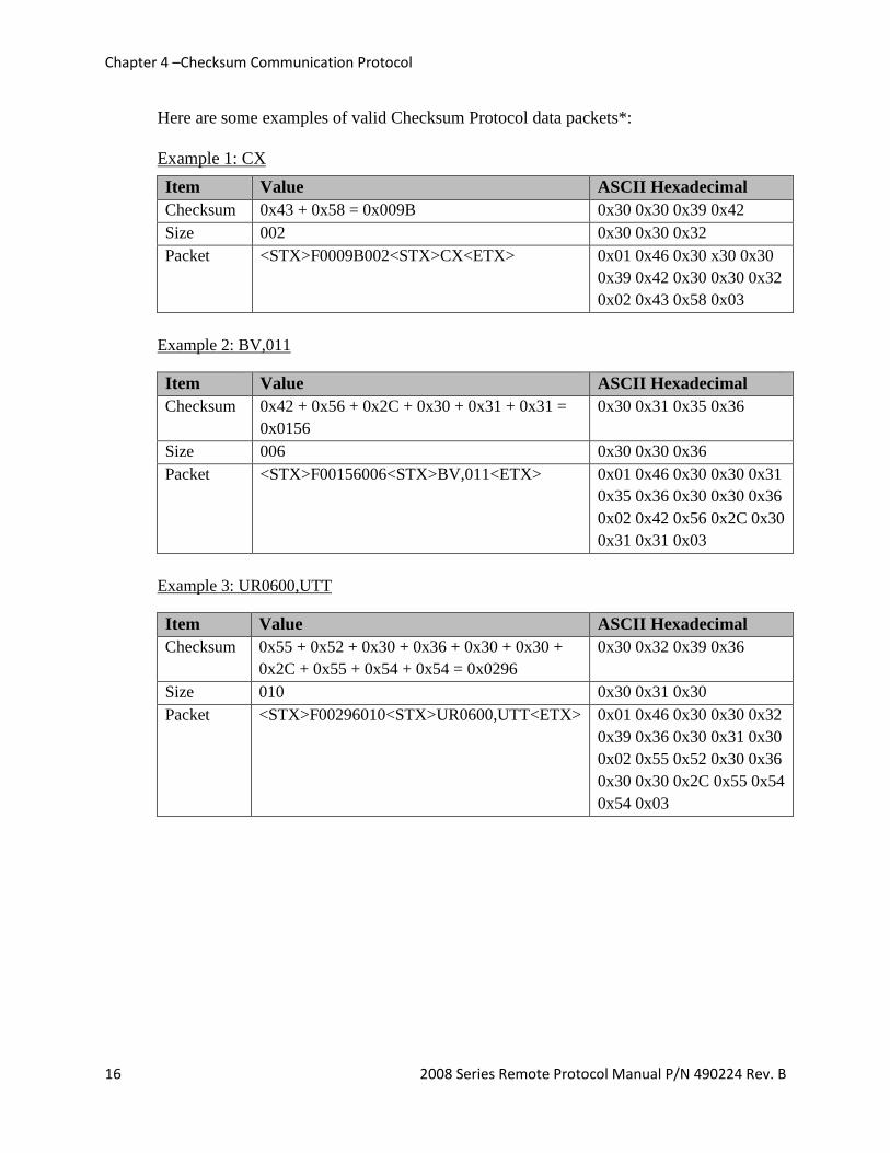
Here are some examples of valid Checksum Protocol data packets*:
Example 1: CX
Item Value ASCII Hexadecimal
Checksum 0x43 + 0x58 = 0x009B 0x30 0x30 0x39 0x42
Size 002 0x30 0x30 0x32
Packet <STX>F0009B002<STX>CX<ETX> 0x01 0x46 0x30 x30 0x30
0x39 0x42 0x30 0x30 0x32
0x02 0x43 0x58 0x03
Example 2: BV,011
Item Value ASCII Hexadecimal
Checksum 0x42 + 0x56 + 0x2C + 0x30 + 0x31 + 0x31 =
0x0156
0x30 0x31 0x35 0x36
Size 006 0x30 0x30 0x36
Packet <STX>F00156006<STX>BV,011<ETX> 0x01 0x46 0x30 0x30 0x31
0x35 0x36 0x30 0x30 0x36
0x02 0x42 0x56 0x2C 0x30
0x31 0x31 0x03
Example 3: UR0600,UTT
Item Value ASCII Hexadecimal
Checksum 0x55 + 0x52 + 0x30 + 0x36 + 0x30 + 0x30 +
0x2C + 0x55 + 0x54 + 0x54 = 0x0296
0x30 0x32 0x39 0x36
Size 010 0x30 0x31 0x30
Packet <STX>F00296010<STX>UR0600,UTT<ETX> 0x01 0x46 0x30 0x30 0x32
0x39 0x36 0x30 0x31 0x30
0x02 0x55 0x52 0x30 0x36
0x30 0x30 0x2C 0x55 0x54
0x54 0x03

Chapter 4 – Checksum Communication Protocol
2008 Series Remote Protocol Manual P/N 490224 Rev. B 17
Example 3: <ACK>
Item Value ASCII Hexadecimal
Checksum 0x06 = 0x0006 0x30 0x30 0x30 0x36
Size 001 0x30 0x30 0x31
Packet <STX>F00006001<STX><ACK><ETX> 0x01 0x46 0x30 0x30 0x30
0x30 0x36 0x30 0x30 0x31
0x02 0x06 0x03
Example 4: <NAK>
Item Value ASCII Hexadecimal
Checksum 0x15 = 0x0015 0x30 0x30 0x31 0x35
Size 001 0x30 0x30 0x31
Packet <STX>F00015001<STX><NAK><ETX> 0x01 0x46 0x30 0x30 0x30
0x31 0x35 0x30 0x30 0x31
0x02 0x15 0x03
Note: With some versions of the 2008T hemodialysis machine, the Negative
Acknowledgement packet has a different format, as seen below. In this packet, no “End of
Transmission” character <ETX> is sent.
Item Value ASCII Hexadecimal
Checksum 0x15 = 0x0015 0x30 0x30 0x31 0x35
Size 001 0x30 0x30 0x31
Packet <STX>F00015001<STX><ACK><NAK> 0x01 0x46 0x30 0x30 0x30
0x31 0x35 0x30 0x30 0x31
0x02 0x06 0x15
* Each example shows the intended data to be transmitted and its corresponding Checksum packet. The
sequence number for all these examples is 0.

Appendix A – Commands
18 2008 Series Remote Protocol Manual P/N 490224 Rev. B
Appendix A
Commands
Command
Code
Meaning Comments
CX Reset communications Send as the first command, or whenever needed
DXF* Turn Green traffic/status light off
DXT* Turn Green traffic/status light on
EXF* Turn Yellow traffic/status light off
EXT* Turn Yellow traffic/status light on
CG Change the color of the communication
icon for a 60-second duration (only
available in Checksum Protocol on the
2008K@Home)
This command changes the color of the communication
icon (phone) in the dialogue box to:
- Grey – power on or dialysis paused
- Green – signal received during treatment
- Red – no signal received in 1 minute during treatment
### Communication interval time. Begin
sending data packets every ### seconds
ASCII number from minimum to 600. Minimum is 10 in
Standard Protocol; minimum is 11 in Checksum Protocol.
If out of range, the interval time defaults to 000.
In Standard Protocol, an interval time of 0 seconds means
that no packets are transmitted from the machine,
regardless of the controls.
In Checksum Protocol, an interval of 0 seconds means
that packets are transmitted continuously from the
machine if there are Field packets to be sent.
* The traffic/status light control can only be enabled by setting an option in the machine’s
Service Mode. To enter Service Mode, turn on the machine and press the [Enter] key when
prompted “Press CONFIRM For Service Mode”. After the machine boots up in Service Mode,
navigate to the Options menu and select Hardware Options. On this screen, the Beacon button
controls the input for the traffic/status light. Use the [Up] and [Down] arrow keys to select
FDS08 and press the [Enter] key to confirm the selection. When using the traffic/status light
commands, it is recommended to turn one light off when turning the other on to avoid confusion.

Appendix B – Group Codes
2008 Series Remote Protocol Manual P/N 490224 Rev. B 19
Appendix B
Group Codes
Group
Code
Data packet sent by the Machine shall include Comments
{} VP, AP, TM, TP, DF, CD, BF, AC, AT, AF, AB, AA,
AR, AV, AU, AL, AN, AD, RI, DS, DI, BS, UR, UT,
SY, DY, PL, MA
Equivalent to sending the following groups:
PR, DI, AL, MS, UF, and BP.
When the machine receives {}, it will return
the appropriate Field Packets immediately and
only once. The internal list will not be updated
by this Control.
Note: Standard Protocol Only
PR VP, AP, TM Pressure Values
DI TP, DF, CD, BF Dialysate Values
AL AC, AT, AF, AB, AA, AR, AV, AU, AL, AN, AD Alarms
Note: AD field for future use.
MS RI, DS, DI, BS Machine States
UF UR, UT Ultra Filtrate Values
BP SY, DY, PL, MA Blood Pressure Module Data
XT UV, BV, PA, UG, RT, MI, UF. UP, SP, NS, NB, BI, ST Extra Values
SS PR, PE, PX, WA, WE Safety System
(only available on the 2008K@Home)
VX VP, VH, VL Venous Group
Note: Standard Protocol Only
BT TA, TV, TB, TE, RE, HA Blood Temperature Module (BTM) and
Heparin Data
CL PN, VS, HC, KO, KE, PK, EK, DK, KT Clearance Data
KS TX, QB, QD, TT, DK, KT, HA, HR Treatment Data
FL FA, P1, P2, P3, P4, P5, P6 Functional Options
BV RB, TR, HT, HB Blood Volume Module (BVM) Data
VR VR Functional Board Version Number
CM CB, CP, CC, CH, CO, MO, OA, BA, CM, CW Crit-Line Module Data
(only available on the 2008T machine, v2.48
or later)

Appendix C – Field Codes
20 2008 Series Remote Protocol Manual P/N 490224 Rev. B
Appendix C
Field Codes
Group
Code
Field
Code
Field Format [units] Send Checksum
Protocol
Only
Comment
Each
Interval
New
Data*
PR VP Venous pressure xxx [mmHg] Also sent in VX group. Send ‘-000’ if no data.
AP Arterial pressure xxx [mmHg] Send ‘-000’ if no data.
TM TMP xxx [mmHg] Send ‘-000’ if no data.
DI TP Monitor Temperature xx.xx [°C] 37.5 °C will be displayed as 3750.
DF Dialysate flow rate xxxx [mL/min.] Send ‘0000’ if the flow is stopped.
CD Conductivity xx.xx [mS/cm] 14.3 mS/cm will be displayed as 1430.
BF Blood flow rate xxxx [mL/min.] Send ‘0000’ if the blood pump is stopped.
Note: On the 2008K machine, this value may be
inaccurate if a Blood Pump Serial Communication
cable (P/N 670658-Q) is not installed. Please see
Bulletin 11-FHK-001 Rev B for more details.
AL AC Conductivity alarm T/F
AT Temperature alarm T/F
AF Dialysate flow alarm T/F
AB Blood pump alarm T/F
AA Level detector alarm T/F
AR Arterial Pressure alarm T/F
AV Venous Pressure alarm T/F
AU TMP alarm T/F
AL Blood leak alarm T/F
AN Check Venous Access Alarm T/F Send ‘T’ if venous needle disconnected.
For 2008K machine only
AD Blood pressure alarm T/F Any systolic, diastolic, pulse, MAP alarm, high or
low. Sent upon occurrence only.
Note: AD field for future use.
MS RI Rinse mode T/F Returns ‘T’ if in Water Rinse.
DS Disinfect mode T/F Returns ‘T’ if in Acid Clean, Chemical Rinse,
Chemical Dwell, or Heat Disinfection.
DI Dialysis mode T/F Returns ‘T’ if in Dialysis Mode.
BS Blood Sensed T/F Returns ‘T’ if blood sensed in Dialysis Mode.

Appendix C – Field Codes
2008 Series Remote Protocol Manual P/N 490224 Rev. B 21
Group
Code
Field
Code
Field Format [units] Send Checksum
Protocol
Only
Comment
Each
Interval
New
Data*
UF UR UF flow rate xxxx [mL/h] Send ‘0000’ if UF off.
UT UF flow on T/F Send ‘T’ if UF on.
BP SY Systolic pressure xxx [mmHg]
DY Diastolic pressure xxx [mmHg]
PL Pulse xxx [bpm]
MA Mean Arterial Pressure (MAP) xxx [mmHg]
XT
UV UF removed xxxx [mL]
BV Blood volume processed xxx.xx [L] (BTM)
xxx.x [L] (else)
BV is sent with an extra digit if BTM group is
selected, else sent with only 4 digits.
PA** Patient ID String 2008T: 10 characters.
2008H: 6 characters
No data string sent if there is no patient ID.
UG UF goal xxxx [mL]
RT Remaining Time of Dialysis (RTD) xxxx [sec.]
MI*** Machine ID String Send up to 9 characters (e.g. ‘machine01’). If less
than 9 characters, send trailing spaces (e.g.
‘mchine1 ’).
Send ‘000000000’ if no data.
UF UF Time xxxx [sec.]
UP UF profile # xxx
SP SVS profile xxx Send only if SVS program is active:
000: SVS program off
001: Step SVS program
002: Linear SVS program
003: Exponent SVS program
NS SVS On/Off T/F
NB Na base xxxx [mEq/L]
BI Na start xxxx [mEq/L]
ST Bicarbonate xxxx [mEq/L]
SS PR Pulse Rate from Pulse Oximeter xxx [bpm] Send ‘000’ if no data.
PE Pulse Error T/F For all warnings, send ‘T’ if Pulse Oximeter Error
occurred.
PX Pulse Alarm T/F Defaults to ‘F’.
WA Wetness Alarm T/F Send ‘T’ if wetness detected.
WE
Wetness Error T/F Send ‘T’ if no communication or low battery from
Wetness Detector.
Appendix C – Field Codes
22 2008 Series Remote Protocol Manual P/N 490224 Rev. B
Group
Code
Field
Code
Field Format [units] Send Checksum
Protocol
Only
Comment
Each
Interval
New
Data*
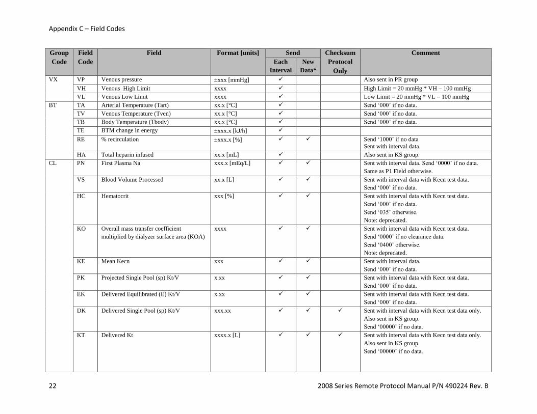
VX VP Venous pressure xxx [mmHg] Also sent in PR group
VH Venous High Limit xxxx High Limit = 20 mmHg * VH – 100 mmHg
VL Venous Low Limit xxxx Low Limit = 20 mmHg * VL – 100 mmHg
BT
TA Arterial Temperature (Tart) xx.x [°C] Send ‘000’ if no data.
TV Venous Temperature (Tven) xx.x [°C] Send ‘000’ if no data.
TB Body Temperature (Tbody) xx.x [°C] Send ‘000’ if no data.
TE BTM change in energy xxx.x [kJ/h]
RE % recirculation xxx.x [%] Send ‘1000’ if no data
Sent with interval data.
HA Total heparin infused xx.x [mL] Also sent in KS group.
CL
PN First Plasma Na xxx.x [mEq/L] Sent with interval data. Send ‘0000’ if no data.
Same as P1 Field otherwise.
VS Blood Volume Processed xx.x [L] Sent with interval data with Kecn test data.
Send ‘000’ if no data.
HC Hematocrit xxx [%] Sent with interval data with Kecn test data.
Send ‘000’ if no data.
Send ‘035’ otherwise.
Note: deprecated.
KO Overall mass transfer coefficient
multiplied by dialyzer surface area (KOA)
xxxx Sent with interval data with Kecn test data.
Send ‘0000’ if no clearance data.
Send ‘0400’ otherwise.
Note: deprecated.
KE Mean Kecn xxx Sent with interval data.
Send ‘000’ if no data.
PK Projected Single Pool (sp) Kt/V x.xx Sent with interval data with Kecn test data.
Send ‘000’ if no data.
EK Delivered Equilibrated (E) Kt/V x.xx Sent with interval data with Kecn test data.
Send ‘000’ if no data.
DK Delivered Single Pool (sp) Kt/V xxx.xx Sent with interval data with Kecn test data only.
Also sent in KS group.
Send ‘00000’ if no data.
KT
Delivered Kt xxxx.x [L] Sent with interval data with Kecn test data only.
Also sent in KS group.
Send ‘00000’ if no data.

Appendix C – Field Codes
2008 Series Remote Protocol Manual P/N 490224 Rev. B 23
Group
Code
Field
Code
Field Format [units] Send Checksum
Protocol
Only
Comment
Each
Interval
New
Data*
KS
TX Tx clock status T/F Send ‘T’ if running or paused. Send ‘F’ if
stopped.
QB Average Blood Flow (Qb) xxxx [mL/min]
QD Average Dialysate Flow (Qd) xxxx [mL/min]
TT Treatment time xxxx [min.]
DK Delivered Single Pool (sp) Kt/V xxx.xx Also sent in CL group.
KT Delivered Kt xxxx.x [L] Also sent in CL group.
HA Total heparin infused xx.x [mL] Also sent in BT group.
HR Heparin rate xx.x [mL/h]
FL FA Access Flow xxxx Send ‘-0000’ if no data.
P1-P6 Plasma Na 1 – Plasma Na 6 xxx.x Sent with OLC Measurement.
BV
RB Relative Blood Volume (RBV) xxx.x [%] Send ‘-0000’ if no data.
TR Trend xxx ↑ ↔
↓
001 002 003 004 005
Otherwise, if Crit-Line, send “000”
HT Hematocrit xxx.x [%] If Crit-Line, send ‘-0000’
HB Hemoglobin (HgB) xxx.x If Crit-Line, send ‘-0000’
VR VR Software version number xx.xx Functional Board version. Version 2.41 will be
returned as 0241
CM
CB RBV (Crit-Line) xxx.x [%] If no Crit-Line, sends ‘-0000’
CP Profile (Crit-Line) 00A, 00B, 00C If no Crit-Line, sends ‘000’
CC Hematocrit xxx.x [%] If no Crit-Line, sends ‘-0000’
CH HgB xxx.x If no Crit-Line, sends ‘-0000’
CO O2 Sat. xxx.x [%] If no Crit-Line, sends ‘-0000’
MO Min. O2 Sat. xxx.x [%] If no Crit-Line, sends ‘-0000’
OA O2 Alert Level xxxx [%] If no Crit-Line, sends ‘-0000’
BA BV Alert Level xxxx [%] If no Crit-Line, sends ‘-0000’
CM Crit-Line Marker 000, SYM, INT 000 – No Marker (or no Crit-Line)
SYM – Symptom Marker
INT – Intervention Marker
CW Crit-Line Warning 000, NCA, SYS,
OBS, NBS, BVA,
O2A, PRF
000 – No Warning (or no Crit-Line)
NCA – No Comm Alert SYS – System Error
OBS – Obstruction NBS – Need Blood Sensed
BVA – BV Alert O2A – O2 Alert
PRF – Print Failure

Appendix C – Field Codes
24 2008 Series Remote Protocol Manual P/N 490224 Rev. B
* Alarms shown in the “New Data” column are sent upon occurrence in the following format:
In the event of a Conductivity Alarm (AC), the data “!AC” will be sent at the time of the alarm and “ACT” will be sent for the
subsequent packets.
Fields shown in the “New Data” column display ‘0’-filled data until new and valid data values are available, unless otherwise stated in
the table. For example, if the ‘BP’ group data is requested by the Host but the Blood Pressure Module data is not available, the
machine should return the field data ‘SY000,DY000,PL000,MA000’.
** The Patient ID may be set by navigating to the Test & Options screen. Select the “Patient ID” button and enter the characters with
the keyboard. Press [Enter] to confirm the entered Patient ID.
*** The Machine ID may be set by entering Service Mode. Navigate to the Options page and select Comm Options. Select the
“Machine Name” button and use the keyboard to enter the Machine ID. Press [Enter] to confirm the entered Machine ID.
Note:
Formats indicated by this table are meant as place holders. “x”s shall be replaced by the characters of the Field Values. Positive signs
(+) and negative signs (-) shall be included in the sent data in the implied position shown. Decimal places (.) are implied and will not
appear in the data packet.
Not all field codes may be returned on all the machines. Group data sent from the Crit-Line module (CM) is only available on the
2008T machine, v2.48 or later. Host software should be written to expect new future Field Codes.
! Field Code


![[MS-RDPEI]: Remote Desktop Protocol: Input Virtual Channel ... · The Remote Desktop Protocol: Input Virtual Channel Extension applies to the Remote Desktop Protocol: Basic Connectivity](https://static.fdocuments.net/doc/165x107/5fb6d5eed3f54f6ff56efb20/ms-rdpei-remote-desktop-protocol-input-virtual-channel-the-remote-desktop.jpg)
![[MS-REMSI]: Remote Media Streaming Initiation Protocol](https://static.fdocuments.net/doc/165x107/62b0fb27a42a305bf96b82af/ms-remsi-remote-media-streaming-initiation-protocol.jpg)


![[MS-RAA]: Remote Authorization API Protocol · 2017-09-06 · This document specifies the Remote Authorization API Protocol. The Remote Authorization API Protocol is a Remote Procedure](https://static.fdocuments.net/doc/165x107/5ecc8fe6feb19b7bbf00b5d8/ms-raa-remote-authorization-api-protocol-2017-09-06-this-document-specifies.jpg)
![[MS-RDPEUDP]: Remote Desktop Protocol: UDP Transport Extension - Microsoft... · 2020-03-01 · Remote Desktop Protocol (RDP): A multi-channel protocol that allows a user to connect](https://static.fdocuments.net/doc/165x107/5e8583f4ed84a91c1b4314fd/ms-rdpeudp-remote-desktop-protocol-udp-transport-extension-microsoft-.jpg)
![[MS-TSRAP]: Telnet Server Remote Administration Protocol...The Telnet Server Remote Administration Protocol is a Distributed Component Object Model (DCOM) Protocol [MS-DCOM] interface](https://static.fdocuments.net/doc/165x107/60b2d507b3d5e976d8381237/ms-tsrap-telnet-server-remote-administration-protocol-the-telnet-server-remote.jpg)


![[MS-RAP]: Remote Administration Protocol... · [MS-RAP]: Remote Administration Protocol Intellectual Property Rights Notice for Open Specifications Documentation](https://static.fdocuments.net/doc/165x107/5fc269c9d39f283fa628d2e6/ms-rap-remote-administration-protocol-ms-rap-remote-administration-protocol.jpg)