2007 CARTS Decoupling Solutions - including D-Stick, D - Kemet
14
©2007 Electronic Components, Assemblies & Materials Association (ECA), Arlington, VA CARTS 2007 Symposium Proceedings, Albuquerque, NM, March 2007 Page 1 of 14 Decoupling Solutions Michael Randall, Bill Sloka, Mark Laps, Garry Renner, John Prymak, Peter Blais, Aziz Tajuddin KEMET Electronics Corporation, 201 Fairview Street Extension, Fountain Inn, SC 29644 Phone: 864-409-5611, FAX: 864-409-5642 e-mail: [email protected] Abstract Integrated circuit (IC) technology has advanced over time, requiring innovative decoupling capacitor solutions. These solutions have assumed various forms over the years. This paper reviews the advancement of decoupling needs over time, as well as inventive capacitor designs that have addressed advanced decoupling needs. Three new designs are introduced for high speed decoupling; D-Stick TM , D-Pack and L CAP. D-Stick TM and D-Pack products have novel designs and are best used most in interposer applications. Capacitance densities exceeding 175 μF/cm 2 (>1,000μF/in 2 ) combined with ESL values of 1 pH or less, are possible using D-Pack technology with an X7T temperature characteristic. Additionally, the novel design of these devices enables thermal management as well electronic filtering of the DC power to the IC, while taking up no additional board space. These products are intended for very high performance decoupling needs. L CAP is a high capacitance per unit volume, reduced inductance, board flexure robust, two-terminal MLCC that is intended for use with standard MLCC pad geometries. Introduction Use of decoupling capacitors are in the electronics industry is ubiquitous as decoupling capacitors are typically associated with microprocessors. It is arguable that the majority of multilayer ceramic capacitors (MLCC) sold are used in some type of decoupling. With time, decoupling applications have evolved. A typical decoupling scheme has several levels of decoupling capacitance as the distance from power supply to an IC is traversed. The basic premise behind decoupling is that a capacitor is placed between power and ground of an integrated circuit, typically a microprocessor. The objective is for the capacitor to act as a local source of charge that provides enough current to the switching elements in the IC such to maintain the reference voltage on the switching elements of the IC. If decoupling is inadequate, the IC may experience voltage droop as well as signal pulse rounding, possibly resulting in erroneous switching of the IC switching elements (usually a non- switch). Decoupling is typically achieved at several levels in the power design of an electronic system, each higher level “cascading” to a lower level of decoupling. The need is usually for inductance of the decoupling capacitors to decrease with decoupling level, as the IC is approached, while capacitance requirements also decrease as the IC is approached. Design for optimal decoupling is well described in the literature. 1,2,3 As microprocessor (μP) switching speeds increase in concert with reductions in μP voltages, requirements for high performance decoupling solutions have expanded. The classic application for decoupling of ICs is use of MLCC at the computer processing unit (CPU). MLCC are typically used on the motherboard near the socket and on the microprocessor packaging of the CPU. The MLCC used on the motherboard near the CPU are typically two terminal capacitors utilizing a design configuration that maximizes capacitance per unit volume (CV) in the most cost effective manner (i.e., a standard MLCC configuration), while the MLCC used on the μP package of the CPU are typically optimized for minimum inductance in a small size package, such that the footprint of the CPU does not have to increase significantly due to on package MLCC. Increasing the footprint of the CPU not only results in higher materials cost and reduced performance, it also can be an issue with respect to thermal stresses, especially for CPU utilizing ceramic packaging. On-package decoupling is typically done either on the top side or the bottom side of the μP package board. Both methods have advantages as well as limitations. Figure 1 illustrates examples of top side and bottom side decoupling. The major advantage of top side decoupling is that it enables the package designer to use the entire bottom surface of the μP package for input/output (I/O) structures as shown in figure 2, thereby enabling a
Transcript of 2007 CARTS Decoupling Solutions - including D-Stick, D - Kemet

©2007 Electronic Components, Assemblies & Materials Association (ECA), Arlington, VA CARTS 2007 Symposium Proceedings, Albuquerque, NM, March 2007
Page 1 of 14
Decoupling Solutions
Michael Randall, Bill Sloka, Mark Laps, Garry Renner, John Prymak, Peter Blais, Aziz Tajuddin
KEMET Electronics Corporation, 201 Fairview Street Extension, Fountain Inn, SC 29644
Phone: 864-409-5611, FAX: 864-409-5642 e-mail: [email protected]
Abstract
Integrated circuit (IC) technology has advanced over time, requiring innovative decoupling capacitor solutions. These solutions have assumed various forms over the years. This paper reviews the advancement of decoupling needs over time, as well as inventive capacitor designs that have addressed advanced decoupling needs. Three new designs are introduced for high speed decoupling; D-StickTM, D-Pack and L CAP. D-StickTM and D-Pack products have novel designs and are best used most in interposer applications. Capacitance densities exceeding 175 µF/cm2 (>1,000µF/in2) combined with ESL values of 1 pH or less, are possible using D-Pack technology with an X7T temperature characteristic. Additionally, the novel design of these devices enables thermal management as well electronic filtering of the DC power to the IC, while taking up no additional board space. These products are intended for very high performance decoupling needs. L CAP is a high capacitance per unit volume, reduced inductance, board flexure robust, two-terminal MLCC that is intended for use with standard MLCC pad geometries.
Introduction
Use of decoupling capacitors are in the electronics industry is ubiquitous as decoupling capacitors are typically associated with microprocessors. It is arguable that the majority of multilayer ceramic capacitors (MLCC) sold are used in some type of decoupling. With time, decoupling applications have evolved. A typical decoupling scheme has several levels of decoupling capacitance as the distance from power supply to an IC is traversed. The basic premise behind decoupling is that a capacitor is placed between power and ground of an integrated circuit, typically a microprocessor. The objective is for the capacitor to act as a local source of charge that provides enough current to the switching elements in the IC such to maintain the reference voltage on the switching elements of the IC. If decoupling is inadequate, the IC may experience voltage droop as well as signal pulse rounding, possibly resulting in erroneous switching of the IC switching elements (usually a non-switch). Decoupling is typically achieved at several levels in the power design of an electronic system, each higher level “cascading” to a lower level of decoupling. The need is usually for inductance of the decoupling capacitors to decrease with decoupling level, as the IC is approached, while capacitance requirements also decrease as the IC is approached. Design for optimal decoupling is well described in the literature.1,2,3 As microprocessor (µP) switching speeds increase in concert with reductions in µP voltages, requirements for high performance decoupling solutions have expanded. The classic application for decoupling of ICs is use of MLCC at the computer processing unit (CPU). MLCC are typically used on the motherboard near the socket and on the microprocessor packaging of the CPU. The MLCC used on the motherboard near the CPU are typically two terminal capacitors utilizing a design configuration that maximizes capacitance per unit volume (CV) in the most cost effective manner (i.e., a standard MLCC configuration), while the MLCC used on the µP package of the CPU are typically optimized for minimum inductance in a small size package, such that the footprint of the CPU does not have to increase significantly due to on package MLCC. Increasing the footprint of the CPU not only results in higher materials cost and reduced performance, it also can be an issue with respect to thermal stresses, especially for CPU utilizing ceramic packaging. On-package decoupling is typically done either on the top side or the bottom side of the µP package board. Both methods have advantages as well as limitations. Figure 1 illustrates examples of top side and bottom side decoupling. The major advantage of top side decoupling is that it enables the package designer to use the entire bottom surface of the µP package for input/output (I/O) structures as shown in figure 2, thereby enabling a

©2007 Electronic Components, Assemblies & Materials Association (ECA), Arlington, VA CARTS 2007 Symposium Proceedings, Albuquerque, NM, March 2007
Page 2 of 14
minimum footprint for the µP which saves board space, and reduces thermal cycling stresses. Top side decoupling has two major disadvantages. The thickness of the MLCC used for top side decoupling is limited as the thickness of the silicon IC is typically minimized for thermal management reasons and overall package height reasons. This limits the capacitance values that can be utilized for top side decoupling to low profile MLCC. Additionally, the parasitic inductances involved with top side decoupling are usually higher than with bottom side decoupling since the distance from the decoupling capacitors to the microprocessor (through the power and ground planes) is greater than with bottom side decoupling as illustrated in figure 3. Finally, top side decoupling can limit options for µP lid and heat sink design as top side µP package real estate is used to mount the top side MLCC. While bottom side decoupling enables placement of the decoupling MLCC in closer vicinity to the IC, it uses valuable real estate on the bottom side of the µP package, requiring the footprint of the package to increase significantly (see figure 1, right side). In the case in figure 1, over 20% of the package footprint area is dedicated to bottom side decoupling. For advanced, high speed µP systems using ceramic packaging (typically LTCC with Cu metallurgy), the required expansion in footprint using bottom side decoupling is prohibitive due to the increased thermal cycling stresses between the low temperature cofired ceramic (LTCC) package, having coefficient of thermal expansion (CTE) on the order of 10-12 ppm/C and the printed circuit board (PCB) having CTE values typically >16 ppm/C. Clearly an MLCC-based decoupling solution, combining the reduced inductive parasitics associated with bottom side decoupling, and enabling the µP footprint efficiencies associated with top side decoupling is in order. This paper introduces and details a system developed to achieve those goals.
Figure 1. Examples of top side and bottom side decoupling
Figure 2. Bottom of microprocessor package utilizing top side decoupling (compare with right side of figure 1)

©2007 Electronic Components, Assemblies & Materials Association (ECA), Arlington, VA CARTS 2007 Symposium Proceedings, Albuquerque, NM, March 2007
Page 3 of 14
Figure 3. Relative distance of decoupling MLCC for top side vs. bottom side decoupling.
Discussion
KEMET has developed a decoupling solution for µP power decoupling.4 The approach involves placing the MLCC between the µP package and the PCB (motherboard) in a manner that enables the power and ground current to pass directly through the MLCC device. In this configuration, the MLCC provides both traditional decoupling functions, as well as electronic filtering of the power to the µP, and replaces most or all power I/Os (pins or solder balls or the like) with capacitor terminals such that no increase in µP footprint is required (i.e., the major advantage of top side decoupling), while the distance of the MLCC from the IC silicon is minimized as in the case of bottom side decoupling. This solution also enables heat transfer and dissipation from the bottom of the µP package similar to other thermally conducting I/O structures. This structure is called “D-Pack” (for decoupling package) is comprised of specially designed multi-terminal MLCC called “D-StickTM”. A D-Pack device as well as several D-StickTM devices are illustrated in figure 4.
Figure 4. D-Pack and D-StickTM
The D-Pack configuration is designed to replace all power and ground I/Os to the µP package. The pitch of the terminals on the D-Pack matches the pitch on the µP package, as well as the pitch on the PCB motherboard. The thickness of the D-Pack (~1 to 1.5 mm with 1.15 mm for the design illustrated) is designed to work with pin grid array (PGA) packaging as a partial interposer, or with ball grid array (BGA) or land grid array (LGA) packaging as a full interposer as illustrated in figure 5. The planarity of the D-Pack is controlled in order to ensure excellent interconnection and mechanical and electrical connection between the motherboard PCB and the µP package.

©2007 Electronic Components, Assemblies & Materials Association (ECA), Arlington, VA CARTS 2007 Symposium Proceedings, Albuquerque, NM, March 2007
Page 4 of 14
Each D-Pack is comprised of D-Sticks. The number of D-StickTM terminal pairs (top and bottom) and the configuration of the D-Sticks to make-up a specific D-Pack are determined by the number of power and ground I/Os from the motherboard PCB to the µP package. The pitch of the D-Stick terminals is designed to match the pitch of the motherboard PCB to the µP package I/Os as well. Each D-Pack requires only one positioning/placement step each for the motherboard PCB to the µP package respectively. The D-Pack may be reflow mounted either to the motherboard PCB or to the µP package, or to both concurrently, depending upon the process flow needs of the assembly manufacturer. Each D-Pack design can be specially configured to the needs of the customer/µP package designer. The pitch of the D-Pack is typically 1 mm (X and Y directions), but can be adjusted from ~0.5 mm to ~1.5 mm as needed. D-Packs are available as partial interposers (see figure 5). Development is underway for full interposer configurations as well, in order to further match the application needs of the customer (see figure 6).
Figure 5. D-Pack partial interposer design
Figure 6. D-Pack full interposer design
D-Packs may accommodate “checkerboard” polarity configurations for power and ground, or “shorts reduced” configurations as depicted in figure 7. This modular approach to design enables numerous other I/O sequence configurations as well, giving the µP package designer a great deal of flexibility in design.

©2007 Electronic Components, Assemblies & Materials Association (ECA), Arlington, VA CARTS 2007 Symposium Proceedings, Albuquerque, NM, March 2007
Page 5 of 14
Figure 7. "Checkerboard" and "shorts reduced" polarity configurations for power and ground
The overall capacitance of a D-Pack is additive from the D-Sticks. For example, a 100 D-Stick D-Pack made with 100 each of 5 µF D-Sticks will have a net capacitance of ~500 µF. The amount of capacitance in a D-Pack can be varied by D-Stick design as well, ranging from ~1 µF to ~7 µF within a D-Stick, or from ~100 µF to ~700 µF, or as high as ~175 µF per cm2 (~1,130 µF/in2) board space (which would other wise be used for power I/O) for the 100 D-Stick D-Pack example described above. This amount of capacitance in near vicinity to the µP may enable reduction or elimination of higher level decoupling capacitors as well, resulting in further space saving on the motherboard as well as significant cost reduction through elimination of, now unnecessary decoupling capacitor components.

©2007 Electronic Components, Assemblies & Materials Association (ECA), Arlington, VA CARTS 2007 Symposium Proceedings, Albuquerque, NM, March 2007
Page 6 of 14
For the above sample, the total number of I/Os is 400 (200 power I/Os and 200 ground I/Os). Each I/O is designed to accommodate ~1 ampere with minimal T. The through pin resistance of each I/O is on the order of 7.5 mΩ, which is close to that of a 2 mm PGA pin. The capacitance and inductance properties of a D-Pack may be estimated using a simple parallel circuit analogy, the overall inductance of a D-Pack may be estimated by the number of D-Sticks within a D-Pack through the relation:
StickD
StickDPackD N
LL−
−− ≅
where:
LD-Pack is the inductance of the D-Pack LD-Stick is the inductance of each of the component D-Sticks ND-Stick is the number of D-Sticks within a D-Pack (note: assumes all D-StickTM terminals are mounted as in application for inductance measurement)
The overall through pin resistance of the D-Pack may be estimated through the relation:
⎟⎟⎠
⎞⎜⎜⎝
⎛∗
≅
−
−−
2/ OperStickI
StickD
StickDPackD n
N
RR
where:
RD-Pack is the through pin resistance of the D-Pack RD-Stick is the through pin resistance from 1 power to 1 ground terminal of each of the component D-Sticks ND-Stick is the number of D-Sticks within a D-Pack n I/O per Stick is the number of I/O pairs per D-Stick (note: this number is divided by 2 for power and ground). Note: If resistance of all power or ground terminals is measured for the D-StickTM at one time, n = 2
Similarly, the overall impedance from power to ground may be estimated through the relation:
⎟⎟⎠
⎞⎜⎜⎝
⎛∗
≅
−
−−
2/
11
StickperOIStickD
GtoPStickDGtoPPackD n
N
ZZ
where: ZD-Pack is the impedance of the D-Pack from power to ground ZD-Stick is the impedance of each D-StickTM from 1 power terminal to 1 ground terminal of each of the component D-Sticks ND-Stick is the number of D-Sticks within a D-Pack n I/O per Stick is the number of I/O pairs per D-Stick (note: this number is divided by 2 for power and ground). If impedance of all power to all ground terminals is measured for the D-StickTM at one time, n = 2
©2007 Electronic Components, Assemblies & Materials Association (ECA), Arlington, VA CARTS 2007 Symposium Proceedings, Albuquerque, NM, March 2007
Page 7 of 14
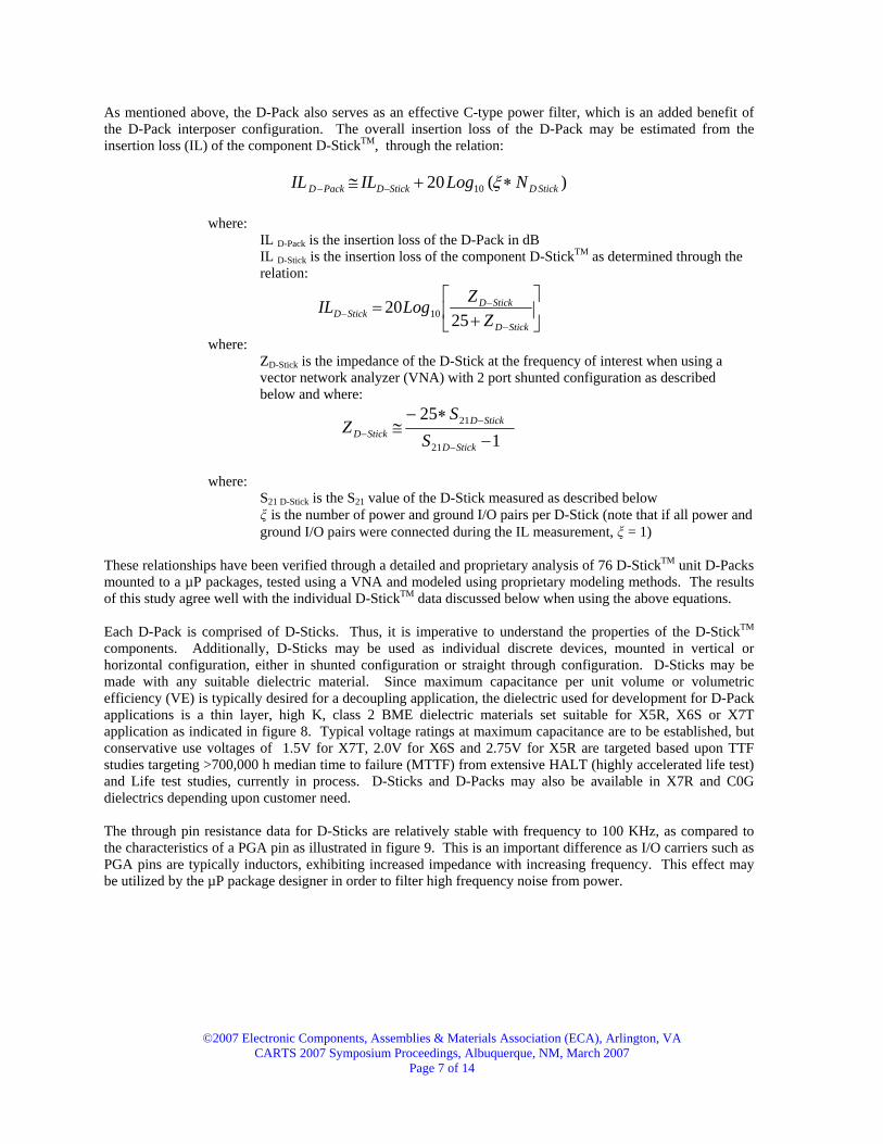
As mentioned above, the D-Pack also serves as an effective C-type power filter, which is an added benefit of the D-Pack interposer configuration. The overall insertion loss of the D-Pack may be estimated from the insertion loss (IL) of the component D-StickTM, through the relation:
)(20 10 StickDStickDPackD NLogILIL ∗+≅ −− ξ
where: IL D-Pack is the insertion loss of the D-Pack in dB IL D-Stick is the insertion loss of the component D-StickTM as determined through the relation:
⎥⎦
⎤⎢⎣
⎡+
=−
−−
StickD
StickDStickD Z
ZLogIL25
20 10
where: ZD-Stick is the impedance of the D-Stick at the frequency of interest when using a vector network analyzer (VNA) with 2 port shunted configuration as described below and where:
125
21
21
−
∗−≅
−
−−
StickD
StickDStickD S
SZ
where:
S21 D-Stick is the S21 value of the D-Stick measured as described below is the number of power and ground I/O pairs per D-Stick (note that if all power and
ground I/O pairs were connected during the IL measurement, = 1) These relationships have been verified through a detailed and proprietary analysis of 76 D-StickTM unit D-Packs mounted to a µP packages, tested using a VNA and modeled using proprietary modeling methods. The results of this study agree well with the individual D-StickTM data discussed below when using the above equations. Each D-Pack is comprised of D-Sticks. Thus, it is imperative to understand the properties of the D-StickTM components. Additionally, D-Sticks may be used as individual discrete devices, mounted in vertical or horizontal configuration, either in shunted configuration or straight through configuration. D-Sticks may be made with any suitable dielectric material. Since maximum capacitance per unit volume or volumetric efficiency (VE) is typically desired for a decoupling application, the dielectric used for development for D-Pack applications is a thin layer, high K, class 2 BME dielectric materials set suitable for X5R, X6S or X7T application as indicated in figure 8. Typical voltage ratings at maximum capacitance are to be established, but conservative use voltages of 1.5V for X7T, 2.0V for X6S and 2.75V for X5R are targeted based upon TTF studies targeting >700,000 h median time to failure (MTTF) from extensive HALT (highly accelerated life test) and Life test studies, currently in process. D-Sticks and D-Packs may also be available in X7R and C0G dielectrics depending upon customer need. The through pin resistance data for D-Sticks are relatively stable with frequency to 100 KHz, as compared to the characteristics of a PGA pin as illustrated in figure 9. This is an important difference as I/O carriers such as PGA pins are typically inductors, exhibiting increased impedance with increasing frequency. This effect may be utilized by the µP package designer in order to filter high frequency noise from power.

©2007 Electronic Components, Assemblies & Materials Association (ECA), Arlington, VA CARTS 2007 Symposium Proceedings, Albuquerque, NM, March 2007
Page 8 of 14
Figure 8. TCC of D-StickTM class 2 high K dielectric system
Figure 9. Through pin resistance (impedance) of PGA pin and D-Stick single termination pair as a function of frequency
However, this type of filtering via the pin is not to ground and is accomplished only through a combination of resistive and inductive loss, which can increase the temperature of the device significantly if the power has a strong ripple or noise component. Since D-Sticks and D-Packs act as C-filters when mounted in an interposer configuration, the noise on the power is filtered to ground in a more effective and thermally efficient manner. Thus, very effective filtering is accomplished without significant heating with this configuration. Using the above equations, the net through pin resistance for a 100 D-StickTM D-Pack is projected to be ~40 µΩ, not considering interconnect (solder or the like) resistances. This value of through pin resistance should enable >250 A current flow with an associated voltage drop of about 10 mV for a 1 V µP power delivery design. This
©2007 Electronic Components, Assemblies & Materials Association (ECA), Arlington, VA CARTS 2007 Symposium Proceedings, Albuquerque, NM, March 2007
Page 9 of 14
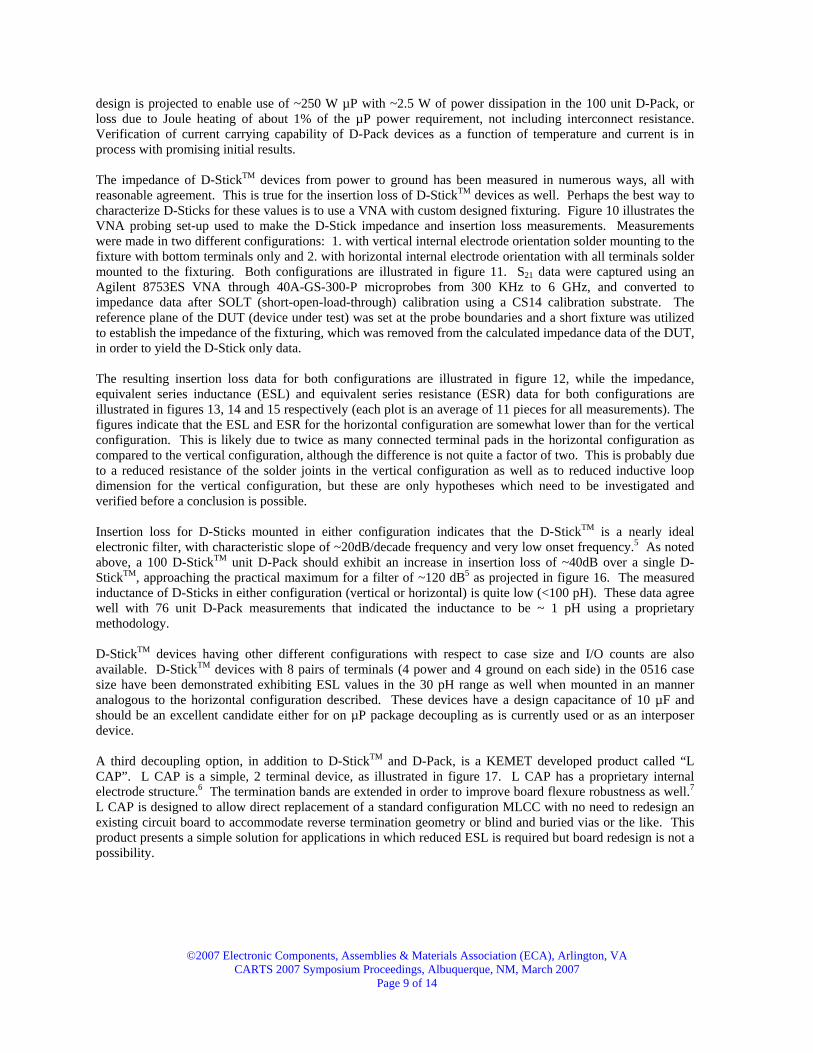
design is projected to enable use of ~250 W µP with ~2.5 W of power dissipation in the 100 unit D-Pack, or loss due to Joule heating of about 1% of the µP power requirement, not including interconnect resistance. Verification of current carrying capability of D-Pack devices as a function of temperature and current is in process with promising initial results. The impedance of D-StickTM devices from power to ground has been measured in numerous ways, all with reasonable agreement. This is true for the insertion loss of D-StickTM devices as well. Perhaps the best way to characterize D-Sticks for these values is to use a VNA with custom designed fixturing. Figure 10 illustrates the VNA probing set-up used to make the D-Stick impedance and insertion loss measurements. Measurements were made in two different configurations: 1. with vertical internal electrode orientation solder mounting to the fixture with bottom terminals only and 2. with horizontal internal electrode orientation with all terminals solder mounted to the fixturing. Both configurations are illustrated in figure 11. S21 data were captured using an Agilent 8753ES VNA through 40A-GS-300-P microprobes from 300 KHz to 6 GHz, and converted to impedance data after SOLT (short-open-load-through) calibration using a CS14 calibration substrate. The reference plane of the DUT (device under test) was set at the probe boundaries and a short fixture was utilized to establish the impedance of the fixturing, which was removed from the calculated impedance data of the DUT, in order to yield the D-Stick only data. The resulting insertion loss data for both configurations are illustrated in figure 12, while the impedance, equivalent series inductance (ESL) and equivalent series resistance (ESR) data for both configurations are illustrated in figures 13, 14 and 15 respectively (each plot is an average of 11 pieces for all measurements). The figures indicate that the ESL and ESR for the horizontal configuration are somewhat lower than for the vertical configuration. This is likely due to twice as many connected terminal pads in the horizontal configuration as compared to the vertical configuration, although the difference is not quite a factor of two. This is probably due to a reduced resistance of the solder joints in the vertical configuration as well as to reduced inductive loop dimension for the vertical configuration, but these are only hypotheses which need to be investigated and verified before a conclusion is possible. Insertion loss for D-Sticks mounted in either configuration indicates that the D-StickTM is a nearly ideal electronic filter, with characteristic slope of ~20dB/decade frequency and very low onset frequency.5 As noted above, a 100 D-StickTM unit D-Pack should exhibit an increase in insertion loss of ~40dB over a single D-StickTM, approaching the practical maximum for a filter of ~120 dB5 as projected in figure 16. The measured inductance of D-Sticks in either configuration (vertical or horizontal) is quite low (<100 pH). These data agree well with 76 unit D-Pack measurements that indicated the inductance to be ~ 1 pH using a proprietary methodology. D-StickTM devices having other different configurations with respect to case size and I/O counts are also available. D-StickTM devices with 8 pairs of terminals (4 power and 4 ground on each side) in the 0516 case size have been demonstrated exhibiting ESL values in the 30 pH range as well when mounted in an manner analogous to the horizontal configuration described. These devices have a design capacitance of 10 µF and should be an excellent candidate either for on µP package decoupling as is currently used or as an interposer device. A third decoupling option, in addition to D-StickTM and D-Pack, is a KEMET developed product called “L CAP”. L CAP is a simple, 2 terminal device, as illustrated in figure 17. L CAP has a proprietary internal electrode structure.6 The termination bands are extended in order to improve board flexure robustness as well.7 L CAP is designed to allow direct replacement of a standard configuration MLCC with no need to redesign an existing circuit board to accommodate reverse termination geometry or blind and buried vias or the like. This product presents a simple solution for applications in which reduced ESL is required but board redesign is not a possibility.

©2007 Electronic Components, Assemblies & Materials Association (ECA), Arlington, VA CARTS 2007 Symposium Proceedings, Albuquerque, NM, March 2007
Page 10 of 14
Figure 10. VNA probe set up for impedance and insertion loss measurements of individual D-Sticks
Figure 11. Device configurations tested
Figure 12. Insertion loss data for D-StickTM

©2007 Electronic Components, Assemblies & Materials Association (ECA), Arlington, VA CARTS 2007 Symposium Proceedings, Albuquerque, NM, March 2007
Page 11 of 14
Figure 13. Impedance data for D-StickTM
Figure 14. Inductance data for D-StickTM

©2007 Electronic Components, Assemblies & Materials Association (ECA), Arlington, VA CARTS 2007 Symposium Proceedings, Albuquerque, NM, March 2007
Page 12 of 14
Figure 15. Power to ground equivalent resistance for D-StickTM
Figure 16. Projected insertion loss for D-Pack
Figure 17. L CAP (1206 EIA, 3216 Metric case size)

©2007 Electronic Components, Assemblies & Materials Association (ECA), Arlington, VA CARTS 2007 Symposium Proceedings, Albuquerque, NM, March 2007
Page 13 of 14
The inductance of L CAP is about 20 to 25% less than the ESL of an equivalent standard configuration MLCC as indicated in figure 18. The median flexure to failure is increased by >70% as illustrated in figure 19 as well. L CAP presents a simple, low cost, reduced inductance, flexure robust solution.
Figure 18. ESL of L CAP vs. Standard MLCC
Figure 19. Board flexure of Standard MLCC vs. L CAP
Summary and Conclusion Decoupling needs have evolved over time. Needs for reduction in ESL, combined with maximization of VE have been important drivers for development of solutions to meet the high speed decoupling needs of customers. D-Pack, a new interposer decoupling solution that combines the benefits of top side and bottom side decoupling without the associated detractors, is a very effective decoupling solution, having very high capacitance (ca. 1,000 µF/in2) in very close proximity to the µP package and with extremely low inductance (ca. 1 pH) without requiring an increase in µP footprint. The D-Pack configuration has very low combined through pin resistance, robbing little power from the µP (~1% or less for a 100 D-StickTM unit D-Pack and 250W µP operating at 1V). D-Pack also enables improved thermal management, as with top side decoupling schemes.
Flexure to Failure (mm)
Perc
ent
Cum
ulat
ive
Failu
re
1086420
99
95
90
80
70
605040
30
20
10
5
1
50
3.97
7.09
Normal - 90% CIControl 1206 X5R 106 vs. L-CAP 1206 X5R 106
Std MLCC
L CAP
Flexure to Failure (mm)
Perc
ent
Cum
ulat
ive
Failu
re
1086420
99
95
90
80
70
605040
30
20
10
5
1
50
3.97
7.09
Normal - 90% CIControl 1206 X5R 106 vs. L-CAP 1206 X5R 106
Std MLCC
L CAP
Standard vs. L CAP MLCC 106 X5R
800
900
1000
1100
1200
1300
1400
1500
1.0E+07 1.0E+08 1.0E+09
Frequency (GHz)
Indu
ctan
ce (p
H)
©2007 Electronic Components, Assemblies & Materials Association (ECA), Arlington, VA CARTS 2007 Symposium Proceedings, Albuquerque, NM, March 2007
Page 14 of 14
Additionally, neither traditional top side nor bottom side decoupling schemes provide a power filtering function with insertion loss in excess of 120 dB as D-Pack does. D-Pack is made up of D-Sticks. This modular concept enables flexibility in D-Pack design for specific applications and customers. D-Sticks may also be used individually in either vertical configuration or horizontal configuration. In these modes, D-Sticks exhibit low inductance (<100 pH) and offer a strong alternative to other low inductance decoupling MLCC options. Finally, L CAP a two-terminal, low inductance, flex robust capacitor design offers an excellent decoupling alternative if board redesign is not an option. L CAP offers a very significant improvement in board flexure performance as well, making it an attractive option for applications requiring reduced inductance from a two terminal flexure robust MLCC. 1 L. Mosley, “Capacitor Impedance Needs for Future Microprocessors,” CARTS USA 2006 Proceedings, pp. 193-203, Orlando, Fl, April 3-6, 2006. 2 www.seattlerobotics.org/encoder/jun97/basics.html 3 A. Martin, “Decoupling Basics,” Technical Information, AVX Corporation. 4 U.S. Patent 7,068,490. Additional patents pending. 5 “Multilayer Ceramic EMI Filters,” Syfer Technology, LTd. 6 Patent pending. 7 U.S. Patent 6,917,510.