2006 US Army LessonPlans C01 Crane PMCS 27p
27
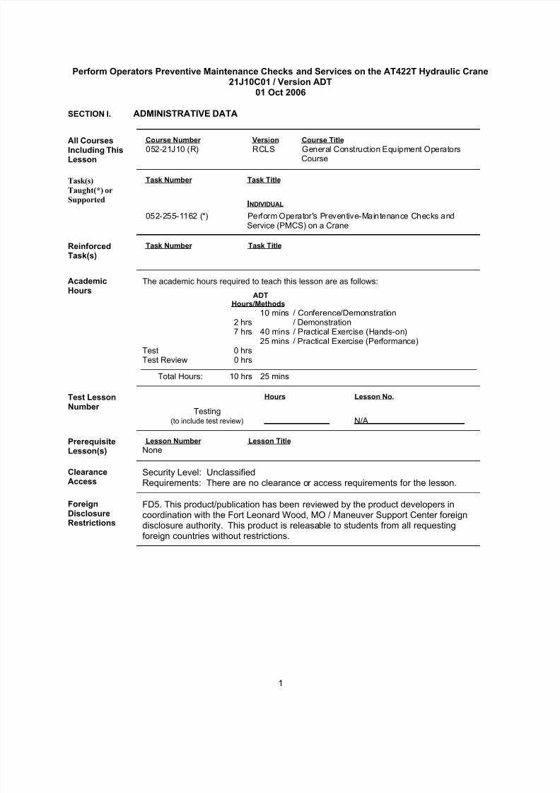
1 Perform Operators Preventive Maintenance Checks and Services on the AT422T Hydraulic Crane 21J10C01 / Version ADT 01 Oct 2006 SECTION I. ADMINISTRATIVE DATA All Courses Including This Lesson Course Number Version Course Title 05 2- 21J10 (R) RCLS General Construction Equipment Op er at or s Course Task(s) Taught(*) or Supported Task Number Task Title INDIVIDUAL 052 -2 55-1162 (*) Per fo rm Op erat or's Preventive-Maint en ance Checks an d Service (PMCS) on a Crane Reinforced Task(s) Task Number Task Title Academic Hours The academic hours required to teach this lesson are as follows: ADT Hours/Methods 10 mins / Con ference /Demo nstrati on 2 hrs / Demonstration 7 hr s 40 mins / Pr acti cal Exer ci se (Hands-on) 25 mins / Pract ical Exer cise (Performan ce) Test 0 hrs Test Review 0 hrs Total Hours: 10 hrs 25 mins Test Lesson Number Hours Lesson No. Testing (to include test review) N/A Prerequisite Lesson(s) Lesson Number Lesson Title None Clearance Access Security Level: Unclassified Requirements: There are no clearance o r access requirements for the less on. Foreign Disclosure Restrictions FD5. This product/publication has been reviewed by the product developers in coordination with the Fort Leonard Wood, MO / Maneuver Support Center foreign disclosure authority. This product is releasa ble to students from all requesting foreign countries without restrictions.
-
Upload
lo-shun-fat -
Category
Documents
-
view
223 -
download
0
Transcript of 2006 US Army LessonPlans C01 Crane PMCS 27p
7/27/2019 2006 US Army LessonPlans C01 Crane PMCS 27p
http://slidepdf.com/reader/full/2006-us-army-lessonplans-c01-crane-pmcs-27p 1/27
1
Perform Operators Preventive Maintenance Checks and Services on the AT422T Hydraulic Crane21J10C01 / Version ADT
01 Oct 2006
SECTION I. ADMINISTRATIVE DATA
All CoursesIncluding ThisLesson
Course Number Version Course Title052-21J10 (R) RCLS General Construction Equipment Operators
Course
Task(s)
Taught(*) or
Supported
Task Number Task Title
INDIVIDUAL
052-255-1162 (*) Perform Operator's Preventive-Maintenance Checks andService (PMCS) on a Crane
ReinforcedTask(s)
Task Number Task Title
AcademicHours
The academic hours required to teach this lesson are as follows:
ADTHours/Methods
10 mins / Conference/Demonstration2 hrs / Demonstration7 hrs 40 mins / Practical Exercise (Hands-on)
25 mins / Practical Exercise (Performance)Test 0 hrsTest Review 0 hrs
Total Hours: 10 hrs 25 mins
Test LessonNumber
Hours Lesson No.
Testing(to include test review) N/A
PrerequisiteLesson(s)
Lesson Number Lesson Title
None
ClearanceAccess
Security Level: UnclassifiedRequirements: There are no clearance or access requirements for the lesson.
ForeignDisclosureRestrictions
FD5. This product/publication has been reviewed by the product developers incoordination with the Fort Leonard Wood, MO / Maneuver Support Center foreigndisclosure authority. This product is releasable to students from all requestingforeign countries without restrictions.
7/27/2019 2006 US Army LessonPlans C01 Crane PMCS 27p
http://slidepdf.com/reader/full/2006-us-army-lessonplans-c01-crane-pmcs-27p 2/27
2
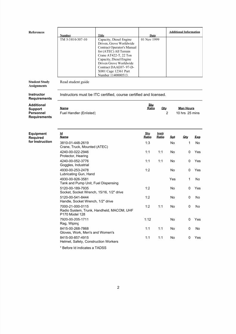
ReferencesNumber Title Date
Additional Information
TM 5-3810-307-10 Capacity, Diesel EngineDriven, Grove WorldwideContract Operator's Manualfor (ATEC) All Terrain
Crane AT422-T, 22 Ton
Capacity, Diesel EngineDriven Grove WorldwideContract DAAE07- 97-D-
X001 Cage 12361 Part Number 1140000513.
01 Nov 1999
Student Study
AssignmentsRead student guide
Instructor Requirements
Instructors must be ITC certified, course certified and licensed.
AdditionalSupport Name
StuRatio Qty Man Hours
Personnel
Requirements
Fuel Handler (Enlisted) 2 10 hrs 25 mins
EquipmentRequired
IdName
StuRatio
Instr Ratio Spt Qty Exp
for Instruction 3810-01-448-2619Crane, Truck, Mounted (ATEC)
1:3 No 1 No
4240-00-022-2946Protector, Hearing
1:1 1:1 No 0 Yes
4240-00-052-3776Goggles, Industrial
1:1 1:1 No 0 Yes
4930-00-253-2478
Lubricating Gun, Hand
1:2 No 0 Yes
4930-00-926-3581Tank and Pump Unit, Fuel Dispensing
Yes 1 No
5120-00-189-7935Socket, Socket Wrench, 15/16, 1/2" drive
1:2 No 0 Yes
5120-00-541-8444Handle, Socket Wrench, 1/2" drive
1:2 No 0 No
7000-21-000-0115Radio System, Trunk, Handheld, MACOM, UHFP170 Model 128
1:2 1:1 No 0 No
7920-00-205-1711Rag, Wiping
1:12 No 0 Yes
8415-00-268-7868
Gloves, Work, Men's and Women's
1:1 1:1 No 0 No
8415-00-857-4915Helmet, Safety, Construction Workers
1:1 1:1 No 0 Yes
* Before Id indicates a TADSS
7/27/2019 2006 US Army LessonPlans C01 Crane PMCS 27p
http://slidepdf.com/reader/full/2006-us-army-lessonplans-c01-crane-pmcs-27p 3/27
3
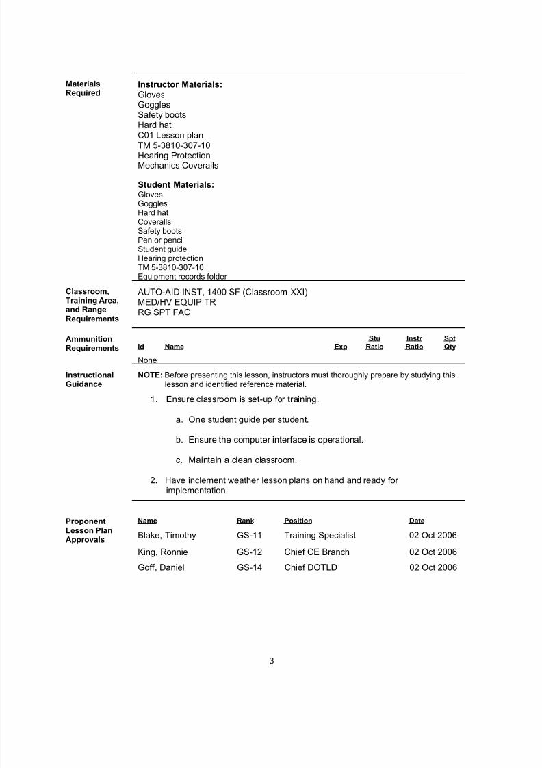
MaterialsRequired
Instructor Materials:GlovesGogglesSafety bootsHard hat
C01 Lesson planTM 5-3810-307-10Hearing ProtectionMechanics Coveralls
Student Materials:GlovesGogglesHard hatCoverallsSafety bootsPen or pencilStudent guideHearing protection
TM 5-3810-307-10Equipment records folder
Classroom,Training Area,and RangeRequirements
AUTO-AID INST, 1400 SF (Classroom XXI)MED/HV EQUIP TRRG SPT FAC
AmmunitionRequirements Id Name Exp
StuRatio
Instr Ratio
SptQty
None
InstructionalGuidance
NOTE: Before presenting this lesson, instructors must thoroughly prepare by studying thislesson and identified reference material.
1. Ensure classroom is set-up for training.
a. One student guide per student.
b. Ensure the computer interface is operational.
c. Maintain a clean classroom.
2. Have inclement weather lesson plans on hand and ready for implementation.
ProponentLesson Plan
Approvals
Name
Blake, Timothy
Rank
GS-11
Position
Training Specialist
Date
02 Oct 2006King, Ronnie GS-12 Chief CE Branch 02 Oct 2006
Goff, Daniel GS-14 Chief DOTLD 02 Oct 2006
7/27/2019 2006 US Army LessonPlans C01 Crane PMCS 27p
http://slidepdf.com/reader/full/2006-us-army-lessonplans-c01-crane-pmcs-27p 4/27
4
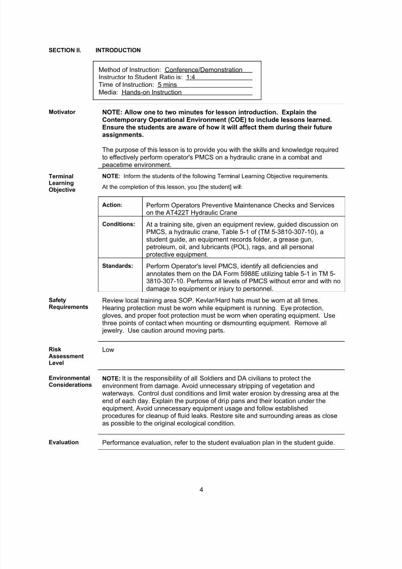
SECTION II. INTRODUCTION
Method of Instruction: Conference/DemonstrationInstructor to Student Ratio is: 1:4Time of Instruction: 5 minsMedia: Hands-on Instruction
Motivator NOTE: Allow one to two minutes for lesson introduction. Explain theContemporary Operational Environment (COE) to include lessons learned.Ensure the students are aware of how it will affect them during their futureassignments.
The purpose of this lesson is to provide you with the skills and knowledge requiredto effectively perform operator's PMCS on a hydraulic crane in a combat andpeacetime environment.
TerminalLearningObjective
NOTE: Inform the students of the following Terminal Learning Objective requirements.
At the completion of this lesson, you [the student] will:
Action: Perform Operators Preventive Maintenance Checks and Serviceson the AT422T Hydraulic Crane
Conditions: At a training site, given an equipment review, guided discussion onPMCS, a hydraulic crane, Table 5-1 of (TM 5-3810-307-10), astudent guide, an equipment records folder, a grease gun,petroleum, oil, and lubricants (POL), rags, and all personalprotective equipment.
Standards: Perform Operator's level PMCS, identify all deficiencies andannotates them on the DA Form 5988E utilizing table 5-1 in TM 5-3810-307-10. Performs all levels of PMCS without error and with nodamage to equipment or injury to personnel.
SafetyRequirements
Review local training area SOP. Kevlar/Hard hats must be worn at all times.Hearing protection must be worn while equipment is running. Eye protection,gloves, and proper foot protection must be worn when operating equipment. Usethree points of contact when mounting or dismounting equipment. Remove all jewelry. Use caution around moving parts.
RiskAssessmentLevel
Low
EnvironmentalConsiderations
NOTE: It is the responsibility of all Soldiers and DA civilians to protect theenvironment from damage. Avoid unnecessary stripping of vegetation andwaterways. Control dust conditions and limit water erosion by dressing area at the
end of each day. Explain the purpose of drip pans and their location under theequipment. Avoid unnecessary equipment usage and follow establishedprocedures for cleanup of fluid leaks. Restore site and surrounding areas as closeas possible to the original ecological condition.
Evaluation Performance evaluation, refer to the student evaluation plan in the student guide.
7/27/2019 2006 US Army LessonPlans C01 Crane PMCS 27p
http://slidepdf.com/reader/full/2006-us-army-lessonplans-c01-crane-pmcs-27p 5/27
5
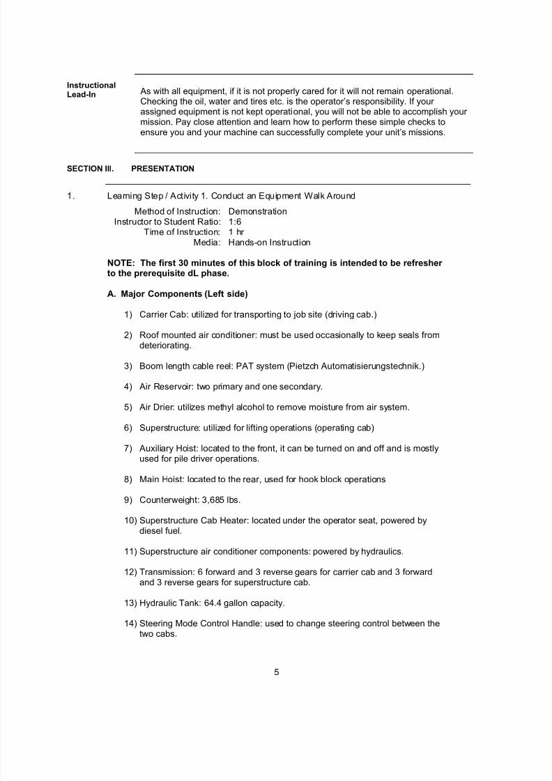
InstructionalLead-In As with all equipment, if it is not properly cared for it will not remain operational.
Checking the oil, water and tires etc. is the operator’s responsibility. If your assigned equipment is not kept operational, you will not be able to accomplish your mission. Pay close attention and learn how to perform these simple checks to
ensure you and your machine can successfully complete your unit’s missions.
SECTION III. PRESENTATION
1. Learning Step / Activity 1. Conduct an Equipment Walk Around
Method of Instruction: DemonstrationInstructor to Student Ratio: 1:6
Time of Instruction: 1 hr Media: Hands-on Instruction
NOTE: The first 30 minutes of this block of training is intended to be refresher
to the prerequisite dL phase.
A. Major Components (Left side)
1) Carrier Cab: utilized for transporting to job site (driving cab.)
2) Roof mounted air conditioner: must be used occasionally to keep seals fromdeteriorating.
3) Boom length cable reel: PAT system (Pietzch Automatisierungstechnik.)
4) Air Reservoir: two primary and one secondary.
5) Air Drier: utilizes methyl alcohol to remove moisture from air system.
6) Superstructure: utilized for lifting operations (operating cab)
7) Auxiliary Hoist: located to the front, it can be turned on and off and is mostlyused for pile driver operations.
8) Main Hoist: located to the rear, used for hook block operations
9) Counterweight: 3,685 lbs.
10) Superstructure Cab Heater: located under the operator seat, powered bydiesel fuel.
11) Superstructure air conditioner components: powered by hydraulics.
12) Transmission: 6 forward and 3 reverse gears for carrier cab and 3 forwardand 3 reverse gears for superstructure cab.
13) Hydraulic Tank: 64.4 gallon capacity.
14) Steering Mode Control Handle: used to change steering control between thetwo cabs.
7/27/2019 2006 US Army LessonPlans C01 Crane PMCS 27p
http://slidepdf.com/reader/full/2006-us-army-lessonplans-c01-crane-pmcs-27p 6/27
6
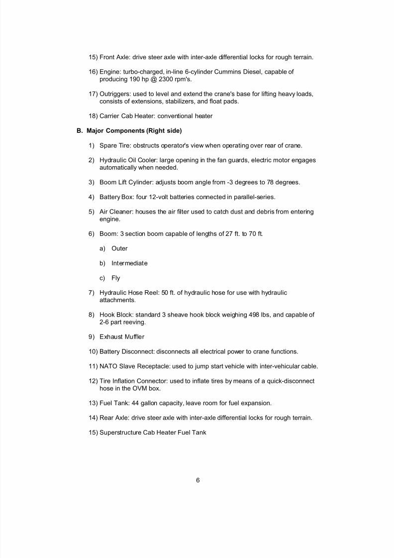
15) Front Axle: drive steer axle with inter-axle differential locks for rough terrain.
16) Engine: turbo-charged, in-line 6-cylinder Cummins Diesel, capable of producing 190 hp @ 2300 rpm's.
17) Outriggers: used to level and extend the crane's base for lifting heavy loads,consists of extensions, stabilizers, and float pads.
18) Carrier Cab Heater: conventional heater
B. Major Components (Right side)
1) Spare Tire: obstructs operator's view when operating over rear of crane.
2) Hydraulic Oil Cooler: large opening in the fan guards, electric motor engagesautomatically when needed.
3) Boom Lift Cylinder: adjusts boom angle from -3 degrees to 78 degrees.
4) Battery Box: four 12-volt batteries connected in parallel-series.
5) Air Cleaner: houses the air filter used to catch dust and debris from enteringengine.
6) Boom: 3 section boom capable of lengths of 27 ft. to 70 ft.
a) Outer
b) Intermediate
c) Fly
7) Hydraulic Hose Reel: 50 ft. of hydraulic hose for use with hydraulicattachments.
8) Hook Block: standard 3 sheave hook block weighing 498 lbs, and capable of 2-6 part reeving.
9) Exhaust Muffler
10) Battery Disconnect: disconnects all electrical power to crane functions.
11) NATO Slave Receptacle: used to jump start vehicle with inter-vehicular cable.
12) Tire Inflation Connector: used to inflate tires by means of a quick-disconnect
hose in the OVM box.
13) Fuel Tank: 44 gallon capacity, leave room for fuel expansion.
14) Rear Axle: drive steer axle with inter-axle differential locks for rough terrain.
15) Superstructure Cab Heater Fuel Tank
7/27/2019 2006 US Army LessonPlans C01 Crane PMCS 27p
http://slidepdf.com/reader/full/2006-us-army-lessonplans-c01-crane-pmcs-27p 7/27
7
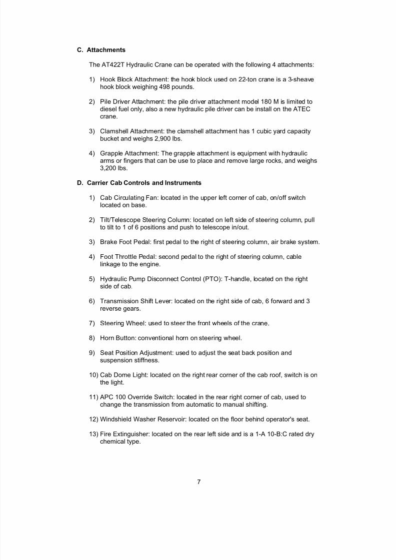
C. Attachments
The AT422T Hydraulic Crane can be operated with the following 4 attachments:
1) Hook Block Attachment: the hook block used on 22-ton crane is a 3-sheavehook block weighing 498 pounds.
2) Pile Driver Attachment: the pile driver attachment model 180 M is limited todiesel fuel only, also a new hydraulic pile driver can be install on the ATECcrane.
3) Clamshell Attachment: the clamshell attachment has 1 cubic yard capacitybucket and weighs 2,900 lbs.
4) Grapple Attachment: The grapple attachment is equipment with hydraulicarms or fingers that can be use to place and remove large rocks, and weighs3,200 lbs.
D. Carrier Cab Controls and Instruments
1) Cab Circulating Fan: located in the upper left corner of cab, on/off switchlocated on base.
2) Tilt/Telescope Steering Column: located on left side of steering column, pullto tilt to 1 of 6 positions and push to telescope in/out.
3) Brake Foot Pedal: first pedal to the right of steering column, air brake system.
4) Foot Throttle Pedal: second pedal to the right of steering column, cablelinkage to the engine.
5) Hydraulic Pump Disconnect Control (PTO): T-handle, located on the rightside of cab.
6) Transmission Shift Lever: located on the right side of cab, 6 forward and 3reverse gears.
7) Steering Wheel: used to steer the front wheels of the crane.
8) Horn Button: conventional horn on steering wheel.
9) Seat Position Adjustment: used to adjust the seat back position andsuspension stiffness.
10) Cab Dome Light: located on the right rear corner of the cab roof, switch is onthe light.
11) APC 100 Override Switch: located in the rear right corner of cab, used tochange the transmission from automatic to manual shifting.
12) Windshield Washer Reservoir: located on the floor behind operator's seat.
13) Fire Extinguisher: located on the rear left side and is a 1-A 10-B:C rated drychemical type.

7/27/2019 2006 US Army LessonPlans C01 Crane PMCS 27p
http://slidepdf.com/reader/full/2006-us-army-lessonplans-c01-crane-pmcs-27p 8/27
8
14) Four Way Flasher Switch: located on the steering column behind turn signallever.
15) Turn Signal Lever: located on the left side of the steering column.
16) NATO Light Switch: military style light control.
17) Water Temperature Gauge: located on the middle left side of control panel,should read from 160-280 degrees and operating range is from 160-205degrees.
18) Left Turn Signal Indicator: located on upper left control panel.
19) Transmission Oil Temperature Gauge: located on the upper left of the controlpanel, should read from 160-320 degrees and operating range is from 160-250 degrees.
20) Air Pressure Gauge: located on the upper left of the control panel, Operatingrange is 10-150 psi. Red needle indicates primary air pressure and thegreen needle indicates secondary air pressure.
21) Hydraulic Pump Engage Indicator: located on the upper left of the controlpanel, red indicator.
22) Differential Lock Indicator: located on the upper left of the control panel,indicates red when either the front and/or the rear differentials are locked.
23) Low Air Pressure Indicator: located on the upper left of the control panel,indicates red when air pressure drops below 75 psi.
24) Carrier Steering Disengaged Indicator: located on the upper middle of thecontrol panel, indicates when the Steering Mode Control Handle is in the outposition.
25) Steering Pump Fail Indicator: located on the upper middle of the controlpanel, indicates when pressure drops in the steering circuit.
26) Fuel Preheat Indicator: located on the upper middle of the control panel,indicates when the thermostat engages the two diesel pre-heaters located inthe fuel lines and fuel/water separator (below 30 degrees).
27) Low Engine Oil Pressure Indicator: located on the upper middle of the controlpanel, indicates red when engine oil pressure drops below 10 psi. Buzzer also sounds to alert operator.
28) Tachometer Gauge: located in the center of the control panel, gauged 0-40
RPM's x 100.
29) Hour Meter: located in the lower portion of the tachometer, registers machineengine hours.
30) Volt Meter: located on the lower left of the control panel, reads between 20-32 volts. Operating range is from 24-28 volts.
7/27/2019 2006 US Army LessonPlans C01 Crane PMCS 27p
http://slidepdf.com/reader/full/2006-us-army-lessonplans-c01-crane-pmcs-27p 9/27
9
31) Axle Differential Lock Switch: located on the lower left of the control panel, a3-way toggle switch. Only engages when 4WD is activated. Do not engagewhile wheels are slipping or spinning.
32) Engine Oil Pressure Gauge: located on the left center of the control panel,gauged from 0-100 psi. Normal operation at idle is 35 psi and 85 psi at highRPM.
33) Fuel Gauge: located on the lower left of the control panel.
34) Drive Axle Selector Switch: located on the lower left of the control panel,switch has two positions: 2WD or 4WD. If switching from 2WD to 4WD,speed must be below 11MPH and 2WD reactivated as soon as tractionpermits.
35) Windshield Wiper Switch: located on the lower left of the control panel, similar to a conventional wiper switch.
36) Engine Water Temperature Indicator: located on the upper right of the controlpanel, indicates when temperature exceeds 205 degrees.
37) Transmission Oil Temperature Indicator: located on the upper right of thecontrol panel, indicates when temperature exceeds 250 degrees.
38) Transmission RPM/Pressure Indicator: located on the upper right of thecontrol panel, amber indicator illuminates when transmission is in an over speed condition.
39) Torque Converter On Lock Indicator: located on the upper right of the controlpanel, amber indicator illuminates when the torque converter is in theunlocked position.
40) Park Brake Indicator: located on the upper right of the control panel, indicates
red when park brake is engaged.
41) Heater Control: located on the upper right of the control panel, pull out for warm temperatures.
42) Heater Fan Switch: located on the upper right of the control panel, 3-positiontoggle switch (HI, OFF, and LOW).
43) Defroster Control Knob: located on the upper right of the control panel, pullout to divert air to the window defroster.
44) Right Turn Signal Indicator: located on the upper right of the control panel.
45) Park Brake Control: located on the middle of the control panel, (YellowButton).
46) Trailer Brake Control: located on the mid-right of control panel, (Red Button).
47) Rear Steer Lock Engage/Disengage Indicator: located on the lower right of the control panel, two amber lights indicate when rear wheels are locked or are not in a straight position.
7/27/2019 2006 US Army LessonPlans C01 Crane PMCS 27p
http://slidepdf.com/reader/full/2006-us-army-lessonplans-c01-crane-pmcs-27p 10/27
10
48) Rear Axle Steering Lock Switch: located on the lower right of the controlpanel, two positions.
49) Rear Axle Steering Control Switch: located on the lower right of the controlpanel, three-way spring loaded toggle switch.
50) Rear Steer Direction Indicator: located on the lower right of the control panel,three lights indicate rear wheel positioning.
51) Ignition Switch: located on the lower right of the control panel, four positions-(3) ACC, (0) OFF, (1) RUN, and (2) START. Switch is spring loaded fromSTART to RUN.
52) Odometer: located at the bottom of the speedometer.
53) Speedometer: located on the middle right of the control panel, gaugedbetween 0-80 MPH and 0-120 KPH.
54) Headlight High Beam Indicator: located in the speedometer on the upper leftside, blue light.
E. Superstructure Cab Controls and Indicators
1) Cab Circulating Fan: Same as Carrier Cab
2) Turn Signal Lever: Same as Carrier Cab
3) Four-Way Flasher: Same as Carrier Cab
4) Tilt/Telescope Steering Column: Same as Carrier Cab
5) Foot Throttle Pedal: Same as Carrier Cab, except it is now air actuated andrequires at least 85 psi to operate.
6) Positive Swing Lock Handle: located on the right side of the cab under thearmrest, used to lock the superstructure cab at any angle when rotated.
7) Hoist Rotation Indicators: located on top of both control levers, left-sideauxiliary hoist drum, right-side main hoist drum, soft button that "thumps" theoperators thumbs when the hoist drums rotate.
8) Boom Lift/Main Hoist Control Lever: right side control lever, 360 degreeactivated joy stick.
9) Fire Extinguisher: located between the operators feet on the floor, BC ratedextinguisher.
10) Tele/Clamshell Selector Switch: located on the right-side arm rest, behindcontrol lever-2-position toggle switch.
11) Telescope Engage Indicator: located on the upper left of the control panel,Green light glows when telescope is control by control pedal.
12) Clamshell/Grapple engage indicator: located on the upper left of the controlpanel, indicator glows green when clamshell is engaged.
7/27/2019 2006 US Army LessonPlans C01 Crane PMCS 27p
http://slidepdf.com/reader/full/2006-us-army-lessonplans-c01-crane-pmcs-27p 11/27
11
13) Telescope/Clamshell Control Pedal: located on the left hand side of the cabunder the control panel 3-way pedal.
14) Horn Button-Swing: located on the right-side arm rest, behind control lever.
15) Cab Dome Light: Same as Carrier Cab
16) Brake Foot Pedal: Same as Carrier Cab
17) Horn Button: Same as Carrier Cab, located on steering wheel.
18) Steering Wheel: Same as Carrier Cab
19) Swing Brake ON/OFF Selector Switch: located on the left-side armrest,behind the control lever, prevents the superstructure from swinging when inthe ON position (pull out to disengage).
20) Swing Brake ON Indicator: located on the upper left of the control panel,indicates red when brake is engaged.
21) Swing Auxiliary Hoist Control Lever: left-side control lever, 360 degreeactivated joy stick.
22) Swing Brake Pedal: located on the left side of cab under the control panel,used to slow or stop swinging of the superstructure, swing brake ON/OFFswitch (# 18) must be in the OFF position.
23) Seat Position Adjustment: controls the seat back position and the forward andreverse movement of the seat cushion.
24) Auxiliary Hoist ON/OFF Switch: located on the left-side arm rest, behind thecontrol lever, disengages the auxiliary winch control in the OFF position.
25) Crane Function Power Switch: Located on the upper left of the control panel – On/Off position switch, Off = no power to armrest controls, On = armrestcontrols activated.
26) Transmission Oil Temperature Gauge: Same as Carrier Cab
27) Air Pressure Gauge: Same as Carrier Cab
28) Left Turn Signal Indicator: Same as Carrier Cab
29) Axle Differential Lock Indicator: Same as Carrier Cab
30) Tachometer Gauge: Same as Carrier Cab
31) Voltmeter: Same as Carrier Cab
32) Differential Lock Switch: Same as Carrier Cab
33) Engine Oil Pressure Gauge: Same as Carrier Cab
34) Fuel Gauge: Same as Carrier Cab
7/27/2019 2006 US Army LessonPlans C01 Crane PMCS 27p
http://slidepdf.com/reader/full/2006-us-army-lessonplans-c01-crane-pmcs-27p 12/27
12
35) Bubble Level: located on the bottom left side of control panel, indicates to theoperator when the crane is level for operation.
36) Drive Axle Selector Switch: Same as Carrier Cab
37) Water Temperature Gauge: Same as Carrier Cab
38) Windshield Wiper/Washer Switch: Same as Carrier Cab
39) Outrigger Selector Switches: located on the left side of the control panel. 3-position, spring loaded switches are used in conjunction with the outrigger extend/retract switch.
40) Low Air Pressure Indicator: located on the upper middle portion of the controlpanel, indicates red when air pressure drops below 75 psi.
41) Engine Distress Indicator: located on the upper right portion of the controlpanel, indicated red when engine and transmission temperatures are toohigh or engine oil pressure drops below 10 psi. A buzzer will also soundwhen indicator illuminates.
42) Steering Pump Failed Indicator: Same as Carrier Cab.
43) Park Brake ON Indicator: Same as Carrier Cab.
44) Right Turn Signal Indicator: Same as Carrier Cab
45) Defroster Fan Control Switch: located on the right side of control panel. 3-way switch has the following settings: LOW, OFF, and HIGH.
46) Work Light Switch: located on the right side of control panel.
47) Transmission Shift Lever: Same as Carrier Cab except it only has 3 forward
and reverse gears.
48) Swing Lock Pin Control Lever: located to the lower right side of the controlpanel, handle must be pulled out to move up or down. Superstructure mustbe directly over the front or back to engage.
49) Throttle Control Knob: located on the lower right side of the control panel,mechanical knob is used to control engine RPM's without using the footthrottle.
50) Rear Axle Steering Lock Switch: Same as Carrier Cab
51) Drive/Panel Light Switch: located on the right side of the front control panel,
switch operates the panel lights and the driving lights on the rear of crane.
52) Panel Light Dimmer Control: located below the Drive/Panel Light Switch onthe front right of the control panel, dims or brightens the panel lights.
53) Outrigger Extend/Retract Switch: located on the lower right side of the controlpanel, used in conjunction with the Outrigger Selector Switch (item mm) andStabilizer Switches.
54) Front Axle Steering Control: Same as Carrier Cab
7/27/2019 2006 US Army LessonPlans C01 Crane PMCS 27p
http://slidepdf.com/reader/full/2006-us-army-lessonplans-c01-crane-pmcs-27p 13/27
13
55) Ignition Switch: Same as Carrier Cab
56) Park Brake Control: Same as Carrier Cab
57) A/C control switch: located to the left of the park brake control
58) Load Moment Indicator (LMI): provides continuous crane status information.
59) Heater Control Panel: ON/OFF switch with reset.
F. General Safety Guidelines
NOTE: Stress the importance of individual responsibility in ensuring safetypractices are followed during daily activities at work and at the training site.Explain that safety briefings will be conducted prior to training and after allbreaks and that safe practices will be enforced at all times. Instruct students toreport any unsafe act immediately.
1) Running is prohibited around the equipment in the training area.
2) Horseplay
a) Horseplay during any phase of training will not be tolerated.
b) Horseplay is grounds for removal from the training area until your chain of command can assure the training phase chief of your willingness toreceive training.
3) Hearing Protection
a) Hearing protection is mandatory during training outside the classroom.
b) When running, the equipment is very loud. If you are not wearing hearingprotection, the sound can damage your hearing.
4) Hard Hats
a) Hard hats are mandatory during training outside the classroom.
b) When you are working around equipment, you must wear a hard hat toprotect your head from any falling objects.
5) Prescribed Medications
a) If you are taking any type of medication while in training, inform the senior
instructor immediately.
b) Certain types of medication can make you drowsy. It is recommendedyou do not operate any equipment while taking these medications.
6) Jewelry
a) Do not wear jewelry during the equipment training phase.
7/27/2019 2006 US Army LessonPlans C01 Crane PMCS 27p
http://slidepdf.com/reader/full/2006-us-army-lessonplans-c01-crane-pmcs-27p 14/27
14
b) Remove your identification tags (dog tags) and place them in your pocket.
G. Travel and park line position
1) Backhoe attachment lowered and locked.
2) Boom is centered and locked for travel.
3) Outriggers are fully retracted and locked.
4) Outrigger pads are stowed.
NOTE: Conduct a check on learning and summarize the learning activity.
2. Learning Step / Activity 2. Perform Before Operations PMCS
Method of Instruction: Practical Exercise (Performance)Instructor to Student Ratio: 1:6
Time of Instruction: 25 minsMedia: Hands-on Instruction
NOTE: The students may be tested on this task at any time during this block of instruction. If the student tests out on this task early THEY ARE STILLREQUIRED TO COMPLETE THE ENTIRE BLOCK OF TRAINING.
Conduct a Practical Exercise on Before Operations PMCS
Refer to appendix C for practical exercise instructions.
NOTE: Conduct a check on learning and summarize the learning activity.
3. Learning Step / Activity 3. Demonstrate Starting Procedures
Method of Instruction: DemonstrationInstructor to Student Ratio: 1:6
Time of Instruction: 25 minsMedia: Hands-on Instruction
A. Starting the Crane Carrier
NOTE: Refer students to TM 5-3810-307-10
1) Pre-start procedures
a) Perform a 360 degree walk around inspection.
NOTE: Inform students to ensure crane boom is centered and locked for travel,outriggers are fully retracted and locked, and the outrigger pads are stowed.
b) Perform before operations PMCS IAW TM 5-3810-307-10.
c) Adjust the seat.
7/27/2019 2006 US Army LessonPlans C01 Crane PMCS 27p
http://slidepdf.com/reader/full/2006-us-army-lessonplans-c01-crane-pmcs-27p 15/27
15
d) Adjust the mirrors.
e) Fasten and adjust the seat belt.
f) Ensure parking brake is engaged.
g) Ensure the transmission shift lever is in the neutral position.
h) Ensure the inter axle differential switch lever is in the unlocked position.
NOTE: Refer students to TM 5-3810-307-10
2) Starting Procedures
a) Engage the starter by turning the key to the start position.
NOTE: Inform students if the engine doesn't start after 30 seconds of steadycranking, they must turn the key switch to the off position and let the starter cool down for two minutes before trying again.
b) Release the switch when the engine starts.
c) Check the oil pressure.
NOTE: Warn the students that if the oil pressure does not register on the gaugeimmediately (10-15 seconds), they must turn the switch to the off position.
NOTE: Conduct a check on learning and summarize the learning activity.
4. Learning Step / Activity 4. Perform During Operations PMCS
Method of Instruction: Practical Exercise (Hands-on)
Instructor to Student Ratio: 1:6Time of Instruction: 10 mins
Media: Hands-on Instruction
NOTE: The students may be tested on this task at any time during this block of instruction. If the student tests out on this task early THEY ARE STILLREQUIRED TO COMPLETE THE ENTIRE BLOCK OF TRAINING.
Conduct a Practical Exercise on During Operations PMCS
Refer to appendix C for practical exercise instructions.
NOTE: Conduct a check on learning and summarize the learning activity.
7/27/2019 2006 US Army LessonPlans C01 Crane PMCS 27p
http://slidepdf.com/reader/full/2006-us-army-lessonplans-c01-crane-pmcs-27p 16/27
16
5. Learning Step / Activity 5. Demonstrate Stopping Procedures
Method of Instruction: DemonstrationInstructor to Student Ratio: 1:6
Time of Instruction: 25 minsMedia: Hands-on Instruction
A. Stopping Procedures
1) Depress the brake pedal to complete the stop.
a) Shift the transmission shifter lever into the neutral position.
b) Engage the park brake.
c) Turn off the ignition switch
d) Dismount crane maintaining three points of contact facing the vehicle.
e) Perform a 360 degree walk around and place the chock blocks.
f) Disengage battery disconnect switch.
NOTE: Conduct a check on learning and summarize the learning activity.
6. Learning Step / Activity 6. Perform After Operations PMCS
Method of Instruction: Practical Exercise (Hands-on)Instructor to Student Ratio: 1:6
Time of Instruction: 25 minsMedia: Hands-on Instruction
NOTE: The students may be tested on this task at any time during this block of instruction. If the student tests out on this task early THEY ARE STILLREQUIRED TO COMPLETE THE ENTIRE BLOCK OF TRAINING.
Conduct a Practical Exercise on After Operations PMCS
Refer to appendix C for practical exercise instructions.
NOTE: Conduct a check on learning and summarize the learning activity.

7/27/2019 2006 US Army LessonPlans C01 Crane PMCS 27p
http://slidepdf.com/reader/full/2006-us-army-lessonplans-c01-crane-pmcs-27p 17/27
17
7. Learning Step / Activity 7. Perform Operators PMCS
Method of Instruction: Practical Exercise (Hands-on)Instructor to Student Ratio: 1:4
Time of Instruction: 7 hrs 5 minsMedia: Hands-on Instruction
NOTE: The students may be tested on this task at any time during this block of instruction. If the student tests out on this task early THEY ARE STILLREQUIRED TO COMPLETE THE ENTIRE BLOCK OF TRAINING.
Conduct a Practical Exercise on Operators PMCS
Refer to appendix C for practical exercise instructions.
NOTE: Conduct a check on learning and summarize the learning activity.

7/27/2019 2006 US Army LessonPlans C01 Crane PMCS 27p
http://slidepdf.com/reader/full/2006-us-army-lessonplans-c01-crane-pmcs-27p 18/27
18
SECTION IV. SUMMARY
Method of Instruction: Conference/DemonstrationInstructor to Student Ratio is: 1:4Time of Instruction: 5 minsMedia: Hands-on Instruction
Check onLearning
Determine if the students have learned the material presented by soliciting studentquestions and explanations. Ask the students questions and correctmisunderstandings.
Review /SummarizeLesson
Restate the learning objectives and then check on learning.

7/27/2019 2006 US Army LessonPlans C01 Crane PMCS 27p
http://slidepdf.com/reader/full/2006-us-army-lessonplans-c01-crane-pmcs-27p 19/27
19
SECTION V. STUDENT EVALUATION
TestingRequirements
NOTE: Describe how the student must demonstrate accomplishment of the TLO. Refer student to the Student Evaluation Plan.
FeedbackRequirements
NOTE: Feedback is essential to effective learning. Schedule and provide feedback on theevaluation and any information to help answer students' questions about the test. Provideremedial training as needed.

7/27/2019 2006 US Army LessonPlans C01 Crane PMCS 27p
http://slidepdf.com/reader/full/2006-us-army-lessonplans-c01-crane-pmcs-27p 20/27
A-1
Appendix A - Viewgraph Masters (N/A)

7/27/2019 2006 US Army LessonPlans C01 Crane PMCS 27p
http://slidepdf.com/reader/full/2006-us-army-lessonplans-c01-crane-pmcs-27p 21/27
B-1
Appendix B - Test(s) and Test Solution(s) (N/A)
7/27/2019 2006 US Army LessonPlans C01 Crane PMCS 27p
http://slidepdf.com/reader/full/2006-us-army-lessonplans-c01-crane-pmcs-27p 22/27
C-1
Appendix C - Practical Exercises and Solutions
PRACTICAL EXERCISE(S)/SOLUTION(S) FOR LESSON 1: 21J10C01 version ADT
PRACTICAL EXERCISE SHEET PE1
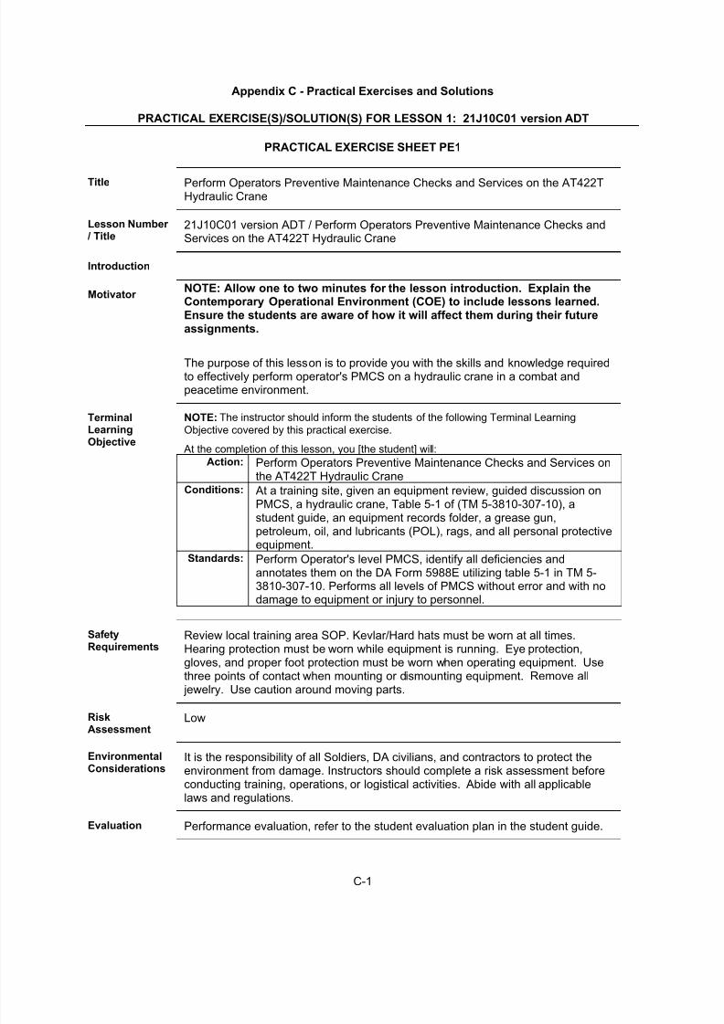
Title Perform Operators Preventive Maintenance Checks and Services on the AT422THydraulic Crane
Lesson Number / Title
21J10C01 version ADT / Perform Operators Preventive Maintenance Checks andServices on the AT422T Hydraulic Crane
Introduction
Motivator NOTE: Allow one to two minutes for the lesson introduction. Explain theContemporary Operational Environment (COE) to include lessons learned.Ensure the students are aware of how it will affect them during their futureassignments.
The purpose of this lesson is to provide you with the skills and knowledge requiredto effectively perform operator's PMCS on a hydraulic crane in a combat andpeacetime environment.
TerminalLearningObjective
NOTE: The instructor should inform the students of the following Terminal Learning
Objective covered by this practical exercise.
At the completion of this lesson, you [the student] will:
Action: Perform Operators Preventive Maintenance Checks and Services onthe AT422T Hydraulic Crane
Conditions: At a training site, given an equipment review, guided discussion onPMCS, a hydraulic crane, Table 5-1 of (TM 5-3810-307-10), astudent guide, an equipment records folder, a grease gun,petroleum, oil, and lubricants (POL), rags, and all personal protectiveequipment.
Standards: Perform Operator's level PMCS, identify all deficiencies andannotates them on the DA Form 5988E utilizing table 5-1 in TM 5-3810-307-10. Performs all levels of PMCS without error and with nodamage to equipment or injury to personnel.
SafetyRequirements
Review local training area SOP. Kevlar/Hard hats must be worn at all times.Hearing protection must be worn while equipment is running. Eye protection,gloves, and proper foot protection must be worn when operating equipment. Usethree points of contact when mounting or dismounting equipment. Remove all jewelry. Use caution around moving parts.
RiskAssessment
Low
EnvironmentalConsiderations
It is the responsibility of all Soldiers, DA civilians, and contractors to protect theenvironment from damage. Instructors should complete a risk assessment beforeconducting training, operations, or logistical activities. Abide with all applicablelaws and regulations.
Evaluation Performance evaluation, refer to the student evaluation plan in the student guide.
7/27/2019 2006 US Army LessonPlans C01 Crane PMCS 27p
http://slidepdf.com/reader/full/2006-us-army-lessonplans-c01-crane-pmcs-27p 23/27
C-2
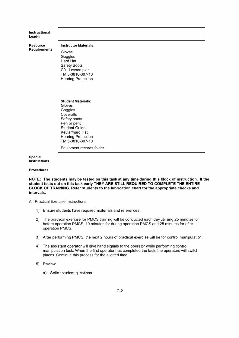
InstructionalLead-In
ResourceRequirements
Instructor Materials:
GlovesGogglesHard HatSafety BootsC01 Lesson planTM 5-3810-307-10Hearing Protection
Student Materials:
GlovesGogglesCoveralls
Safety bootsPen or pencilStudent GuideKevlar/hard HatHearing ProtectionTM 5-3810-307-10
Equipment records folder
SpecialInstructions
Procedures
NOTE: The students may be tested on this task at any time during this block of instruction. If thestudent tests out on this task early THEY ARE STILL REQUIRED TO COMPLETE THE ENTIREBLOCK OF TRAINING. Refer students to the lubrication chart for the appropriate checks andintervals.
A. Practical Exercise Instructions.
1) Ensure students have required materials and references.
2) The practical exercise for PMCS training will be conducted each day utilizing 25 minutes for before operation PMCS, 10 minutes for during operation PMCS and 25 minutes for after operation PMCS.
3) After performing PMCS, the next 2 hours of practical exercise will be for control manipulation.
4) The assistant operator will give hand signals to the operator while performing controlmanipulation task. When the first operator has completed the task, the operators will switchplaces. Continue this process for the allotted time.
5) Review
a) Solicit student questions.

7/27/2019 2006 US Army LessonPlans C01 Crane PMCS 27p
http://slidepdf.com/reader/full/2006-us-army-lessonplans-c01-crane-pmcs-27p 24/27
C-3
b) Ask questions.
c) Correct student misunderstandings.
6) Actively observe students’ progress and provide assistance as necessary throughout theexercise.
7) At the end of training the day, park and secure equipment.
FeedbackRequirements
7/27/2019 2006 US Army LessonPlans C01 Crane PMCS 27p
http://slidepdf.com/reader/full/2006-us-army-lessonplans-c01-crane-pmcs-27p 25/27
C-4
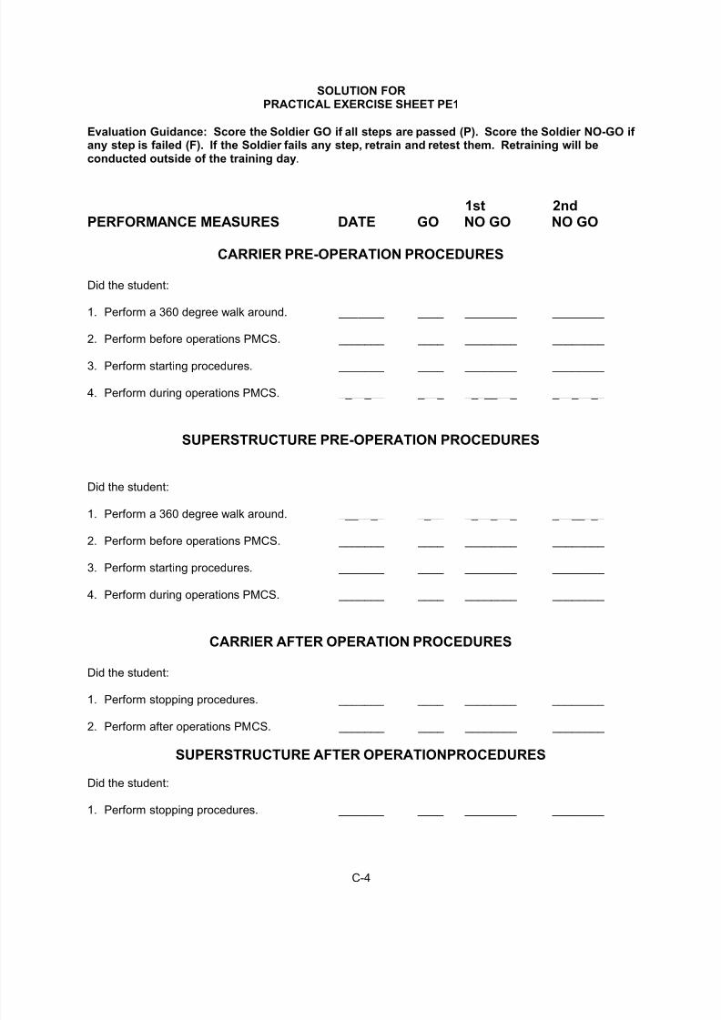
SOLUTION FORPRACTICAL EXERCISE SHEET PE1
Evaluation Guidance: Score the Soldier GO if all steps are passed (P). Score the Soldier NO-GO if any step is failed (F). If the Soldier fails any step, retrain and retest them. Retraining will beconducted outside of the training day.
1st 2ndPERFORMANCE MEASURES DATE GO NO GO NO GO
CARRIER PRE-OPERATION PROCEDURES
Did the student:
1. Perform a 360 degree walk around. _______ ____ ________ ________
2. Perform before operations PMCS. _______ ____ ________ ________
3. Perform starting procedures. _______ ____ ________ ________
4. Perform during operations PMCS. _______ ____ ________ ________
SUPERSTRUCTURE PRE-OPERATION PROCEDURES
Did the student:
1. Perform a 360 degree walk around. _______ ____ ________ ________
2. Perform before operations PMCS. _______ ____ ________ ________
3. Perform starting procedures. _______ ____ ________ ________
4. Perform during operations PMCS. _______ ____ ________ ________
CARRIER AFTER OPERATION PROCEDURES
Did the student:
1. Perform stopping procedures. _______ ____ ________ ________
2. Perform after operations PMCS. _______ ____ ________ ________
SUPERSTRUCTURE AFTER OPERATIONPROCEDURES
Did the student:
1. Perform stopping procedures. _______ ____ ________ ________
7/27/2019 2006 US Army LessonPlans C01 Crane PMCS 27p
http://slidepdf.com/reader/full/2006-us-army-lessonplans-c01-crane-pmcs-27p 26/27
C-5
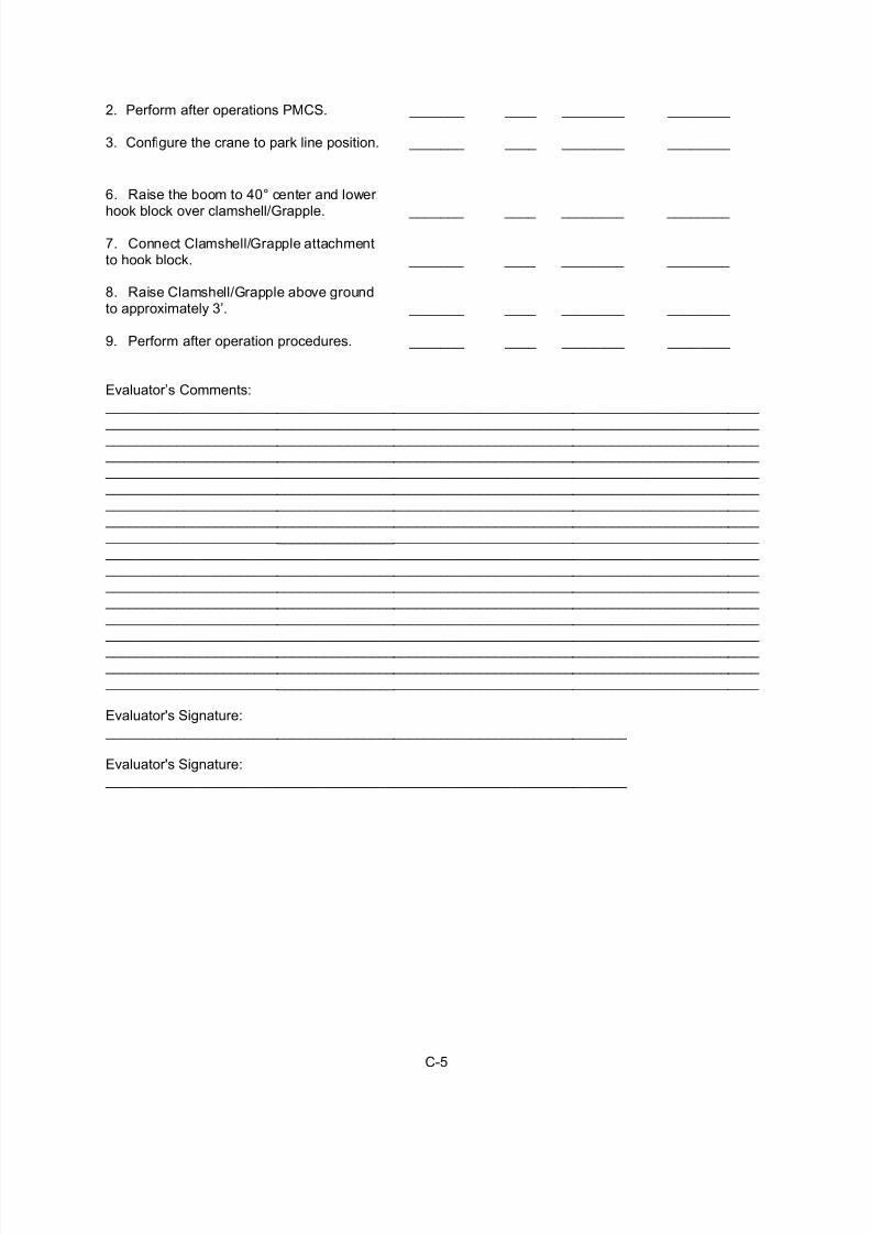
2. Perform after operations PMCS. _______ ____ ________ ________
3. Configure the crane to park line position. _______ ____ ________ ________
6. Raise the boom to 40° center and lower
hook block over clamshell/Grapple. _______ ____ ________ ________
7. Connect Clamshell/Grapple attachmentto hook block. _______ ____ ________ ________
8. Raise Clamshell/Grapple above groundto approximately 3’. _______ ____ ________ ________
9. Perform after operation procedures. _______ ____ ________ ________
Evaluator’s Comments: ____________________________________________________________________________________ ____________________________________________________________________________________ ____________________________________________________________________________________ ____________________________________________________________________________________ ____________________________________________________________________________________ ____________________________________________________________________________________ ____________________________________________________________________________________ ____________________________________________________________________________________ ____________________________________________________________________________________ ____________________________________________________________________________________ ____________________________________________________________________________________ ____________________________________________________________________________________ ____________________________________________________________________________________ ____________________________________________________________________________________ ____________________________________________________________________________________
____________________________________________________________________________________ ____________________________________________________________________________________ ____________________________________________________________________________________
Evaluator's Signature: ___________________________________________________________________
Evaluator's Signature: ___________________________________________________________________

7/27/2019 2006 US Army LessonPlans C01 Crane PMCS 27p
http://slidepdf.com/reader/full/2006-us-army-lessonplans-c01-crane-pmcs-27p 27/27
Appendix D - Student Handouts (N/A)