2006 Int Ansys Conf 40
19
Heat Transfer in Flow Boiling Conditions for Swirl Tube Elements Customizing the ANSYS Software M. Dalla Palma, P. Zaccaria Consorzio RFX, Associazione EURATOM - ENEA sulla Fusione Corso Stati Uniti 4, I-35127, Area della Ricerca del CNR, Padova, Italy Abstract A heat transfer model with water coolant in flow bo iling conditions for swirl tube elements is simulated customizing a programmable routine and relinking the ANSYS code. The standard ANSYS features calculate the film coefficient for forced convection conditions in the single- phase flow wi thout possibilit y of take into acc ount flow boili ng conditions. The heat transfer coefficient is redefined in a general way customizing ANSYS by a user programmable routine to simulate the actual heat transfer in forced convection and flow boiling conditions. The modified routine is called for each iteration, once per element, and during each sub-step of each load-step. The heat transfer coefficient is calculated as a function of heat flux, surface and coolant temperatures, water saturation curve, fluid dynamic properties of coolant, twist tape pitch, and location. A special function is implemented in the customized routine to reduce significantly the number of solution iterations. This function mitigates the heat flux instabilities due to nucleate boiling in the near-wall surface elements. The customized ANSYS code is used to carry out thermo-hydrauli c and thermo-structural analyses for the design of high heat flux components of the neutral beam injector for the international thermonuclear experimental reactor ITER. Introduction The standard ANSYS features calculate the film coefficient for forced convection conditions in single- phase flow. T hese features allow the generation of non-linear parametric models i n which the fi lm coefficient is defined as a material property that varies with fluid dynamic properties of coolant, temperature, and location. In this way the implementati on of the Lopina-Bergles correl ation has been carried out for the film coefficient calculation for forced convection conditions in single phase flow. Modifications of the film coefficient can be considered to take into account the presence of twist tape in the swirl tube elements (STEs) [1]. Heat transfer in flow boiling conditions is foreseen in STEs for application in active cooled high heat flux components to take advantage of increased heat transfer coefficient. The flow boiling heat transfer for water coolant in swirl tube elements is simulated compiling and relinking a user programmable routine in the code. The customized ANSYS code is used to carry out thermo-hydraulic and thermo-structural analyses for the design of active cooled high heat flux components of the neutral beam injector (NBI) for ITER international thermonuclear experime ntal reactor. An accelerated 1 MeV ion beam (40 MW accelerated negative beam power) entering the beam line components is only partially converted into the neutral beam delivered to ITER plasma (16.7 MW neutral beam power). The remaining part is deposited onto the beam line components and exhausted by the NBI cooling system [2]. The peak power density on the elements can reach values up to 25 MW/m 2 , which essentially forces the use of water coolant in nucleate boiling conditions [1]. The code customization and the main results of the thermo-hydraulic and thermo-structura l analyses of the neutralizer leading edge elements (LEEs) are presented in this work.
Transcript of 2006 Int Ansys Conf 40
8/13/2019 2006 Int Ansys Conf 40
http://slidepdf.com/reader/full/2006-int-ansys-conf-40 1/19
Heat Transfer in Flow Boiling Conditions for Swirl TubeElements Customizing the ANSYS Software
M. Dalla Palma, P. Zaccaria
Consorzio RFX, Associazione EURATOM - ENEA sulla FusioneCorso Stati Uniti 4, I-35127, Area della Ricerca del CNR, Padova, Italy
Abstract
A heat transfer model with water coolant in flow boiling conditions for swirl tube elements is simulated
customizing a programmable routine and relinking the ANSYS code.
The standard ANSYS features calculate the film coefficient for forced convection conditions in the single-
phase flow without possibility of take into account flow boiling conditions.
The heat transfer coefficient is redefined in a general way customizing ANSYS by a user programmable
routine to simulate the actual heat transfer in forced convection and flow boiling conditions. The modified
routine is called for each iteration, once per element, and during each sub-step of each load-step. The heat
transfer coefficient is calculated as a function of heat flux, surface and coolant temperatures, watersaturation curve, fluid dynamic properties of coolant, twist tape pitch, and location.
A special function is implemented in the customized routine to reduce significantly the number of solutioniterations. This function mitigates the heat flux instabilities due to nucleate boiling in the near-wall surface
elements.
The customized ANSYS code is used to carry out thermo-hydraulic and thermo-structural analyses for the
design of high heat flux components of the neutral beam injector for the international thermonuclear
experimental reactor ITER.
Introduction
The standard ANSYS features calculate the film coefficient for forced convection conditions in single-
phase flow. These features allow the generation of non-linear parametric models in which the filmcoefficient is defined as a material property that varies with fluid dynamic properties of coolant,
temperature, and location.
In this way the implementation of the Lopina-Bergles correlation has been carried out for the film
coefficient calculation for forced convection conditions in single phase flow. Modifications of the filmcoefficient can be considered to take into account the presence of twist tape in the swirl tube elements
(STEs) [1].
Heat transfer in flow boiling conditions is foreseen in STEs for application in active cooled high heat flux
components to take advantage of increased heat transfer coefficient. The flow boiling heat transfer forwater coolant in swirl tube elements is simulated compiling and relinking a user programmable routine in
the code.
The customized ANSYS code is used to carry out thermo-hydraulic and thermo-structural analyses for thedesign of active cooled high heat flux components of the neutral beam injector (NBI) for ITER
international thermonuclear experimental reactor. An accelerated 1 MeV ion beam (40 MW accelerated
negative beam power) entering the beam line components is only partially converted into the neutral beamdelivered to ITER plasma (16.7 MW neutral beam power). The remaining part is deposited onto the beam
line components and exhausted by the NBI cooling system [2]. The peak power density on the elements can
reach values up to 25 MW/m2, which essentially forces the use of water coolant in nucleate boilingconditions [1]. The code customization and the main results of the thermo-hydraulic and thermo-structural
analyses of the neutralizer leading edge elements (LEEs) are presented in this work.
8/13/2019 2006 Int Ansys Conf 40
http://slidepdf.com/reader/full/2006-int-ansys-conf-40 2/19
Mechanisms of Heat Transfer
Heat exchange in flow boiling conditions means the boiling phenomenon of a fluid in forced convection
flow regime. Two main mechanisms of heat exchange can be identified during the flow boiling conditions:
1) convective boiling,
2) nucleate boiling.
The nucleate boiling (2) is present only if the heat flux exceeds the limit value for the bubbles nucleation
(onset of nucleate boiling) and it occurs when the thermal resistance of the liquid boundary layer doesn’tallow heat exchange by convection, then the over-heating of the liquid near the wall surface is sufficient to
start-up the bubbles nucleation. The heat transfer occurs predominantly by latent heat transport in the vapor
phase that grows at the wall surface. The heat transfer coefficient is predominantly function of the heat flux
and pressure, in spite of the fluid dynamic parameters as flow-rate and vapor quality.
The convective boiling mechanism (1) occurs when the thermal resistance in the liquid boundary layer isless then one in the nucleate boiling and the over-heating of the near-wall liquid is insufficient to start-up
the bubbles nucleation. The heat transfer occurs due to conduction and convection mechanisms in the liquid
layer and due to the evaporation at the interface or in the liquid bulk. The heat transfer is predominantlyfunction of the flow characteristics, as flow-rate, quality, in spite of heat flux and temperature.
Boiling Process in the Tube
The coolant flows in the tube exchanging heat with the wall that is heated from the outer surface of the
tube. The fluid would be under-cooled at the inlet, then the heat transfer would happen by single-phaseconvection. The boiling in the under-cooled liquid occurs when the temperature of the liquid near the
heated surface exceeds the boiling start-up temperature and then the vapor bubbles transport heat in the
liquid bulk. This process (boiling in the under-cooled liquid) increases the liquid temperature along theflow direction and the generated turbulence increases the heat transfer coefficient.
The convective boiling mechanism (1) occurs if the heat flux is insufficient to start-up the bubbles
nucleation. The heat transfer coefficient rises approximately proportionally with the vapor quality after the
saturation is reached. The nucleate boiling mechanism (2) starts as far as the heat flux is high. In general
the two regimes are co-existing.
The liquid layer diminishes as the heat flux increases, the boiling proceeds, and a critical state is reachedwhen the film is completely evaporated leaving dry the wall surface. The flow-rate shall be high enough to
prevent the critical heat flux arising. The net generation of vapor with increase in the quality occurs only
when the vapor generated exceeds the absorbed. The bulk temperature rises up to saturation and then it
decreases due to the pressure drop along the flow direction.
Heat Transfer and Thermo-hydraulic Models
The models implemented in the ANSYS customized codes are expressed by the following conservative
correlations [3, 4].
Forced Convection Coefficient
The film coefficient is calculated in the ANSYS standard features with Lopina-Bergles correlation for
forced convection conditions in the single-phase flow in the presence of the twist tape [5], correctedaccording to reference [6]:
qt(Ti) = αt·(Ti – Tf )
αt = Nut·λ/Dh with Nut = 0.0343·(1+k 2)0.4
·Re0.8
·Pr 0.33
The convection coefficient is split in the product of to coefficients:
8/13/2019 2006 Int Ansys Conf 40
http://slidepdf.com/reader/full/2006-int-ansys-conf-40 3/19
αt = C1·C2
The terms responsible of the geometric characteristics and the flow-rate are collected in the multiplier
factor:
( )8.0
wet
4.02
h
1
P
m4k 1
D
0343.0C
⋅⋅+⋅=
&
where m& is the coolant flow-rate,
Pwet is the wetted perimeter.
C1 is calculated after the definition of the input parameters. A second coefficient considers the dependence
of the thermo-physical properties on temperature:
C2 = λ·(1/µ)0.8
·Pr 0.33
with µ = µ(Tf ) dynamic viscosity,
λ = λ(Tf ) thermal conductivity,
c = c(Tf ) heat capacity at constant pressure,
( ) ( )( )
( )f
f
f f TPr Tλ
TµTcPr =
⋅= is the Prandtl’s number.
The C2 coefficient is plotted versus temperature to define a polynomial function that is introduced in
ANSYS as a material property with linear, quadratic, cubic, and quartic terms.
Flow Boiling Model for STEs
The formulation of the global heat transfer coefficient is based on the classical approach of combining the
Lopina-Bergles equation for single-phase flow in the presence of the twist tape [5], with the Thom equation
for boiling curve correlation [7] and Kutateladze technique for heat flux in fully developed boiling [8]. Theheat transfer coefficient is calculated as a function of heat flux, coolant pressure, water saturation curve,
twist tape pitch, cooling channel geometry, inner wall channel temperature, and fluid dynamic parametersthat vary with temperature.
The following section examines the relations used to carry out the thermo-hydraulic assessment and the
formulae implemented in the ANSYS customized routine to calculate the local heat transfer coefficient in
flow boiling conditions.
Critical Heat Flux
The critical heat flux (CHF) is obtained by the generalized correlation for swirl tubes [1] developed by
Yagov that is selected for simplicity of calculation and extended verification against a wide experimental
database [9]:
CHF = 3.4·ηv0.291
[MW/m2]
with ηv = gn/g0 = k 2·v
2/(g·Dh/2) and k = π·Dh/ttt
8/13/2019 2006 Int Ansys Conf 40
http://slidepdf.com/reader/full/2006-int-ansys-conf-40 4/19
8/13/2019 2006 Int Ansys Conf 40
http://slidepdf.com/reader/full/2006-int-ansys-conf-40 5/19
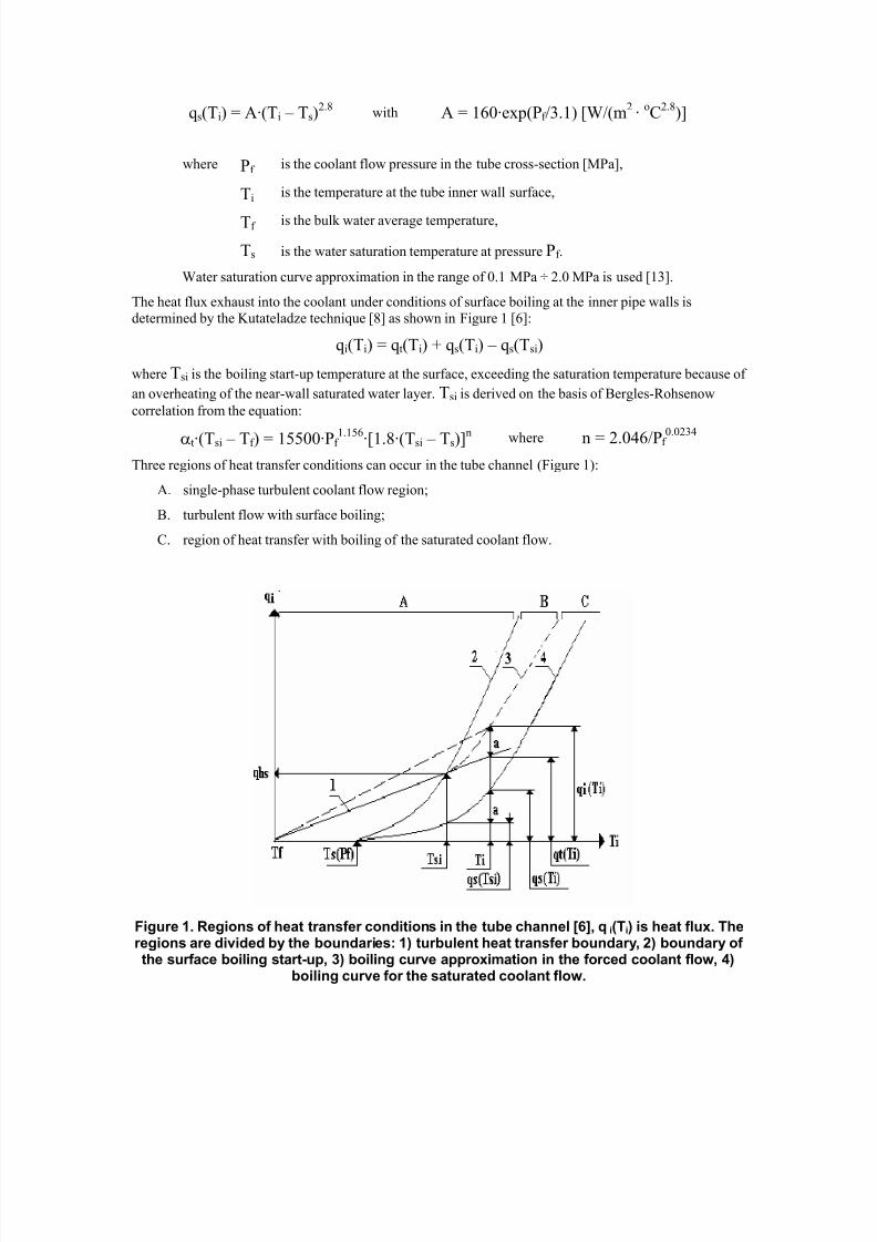
qs(Ti) = A·(Ti – Ts)2.8
with A = 160·exp(Pf /3.1) [W/(m2
·oC
2.8)]
where Pf is the coolant flow pressure in the tube cross-section [MPa],
Ti is the temperature at the tube inner wall surface,
Tf is the bulk water average temperature,
Ts is the water saturation temperature at pressure Pf .
Water saturation curve approximation in the range of 0.1 MPa ÷ 2.0 MPa is used [13].
The heat flux exhaust into the coolant under conditions of surface boiling at the inner pipe walls is
determined by the Kutateladze technique [8] as shown in Figure 1 [6]:
qi(Ti) = qt(Ti) + qs(Ti) – qs(Tsi)
where Tsi is the boiling start-up temperature at the surface, exceeding the saturation temperature because of
an overheating of the near-wall saturated water layer. Tsi is derived on the basis of Bergles-Rohsenow
correlation from the equation:
αt·(Tsi – Tf ) = 15500·Pf 1.156·[1.8·(Tsi – Ts)]n where n = 2.046/Pf 0.0234
Three regions of heat transfer conditions can occur in the tube channel (Figure 1):
A. single-phase turbulent coolant flow region;
B. turbulent flow with surface boiling;
C. region of heat transfer with boiling of the saturated coolant flow.
Figure 1. Regions of heat transfer conditions in the tube channel [6], qi(Ti) is heat flux. Theregions are divided by the boundaries: 1) turbulent heat transfer boundary, 2) boundary ofthe surface boiling start-up, 3) boiling curve approximation in the forced coolant flow, 4)
boiling curve for the saturated coolant flow.
8/13/2019 2006 Int Ansys Conf 40
http://slidepdf.com/reader/full/2006-int-ansys-conf-40 6/19
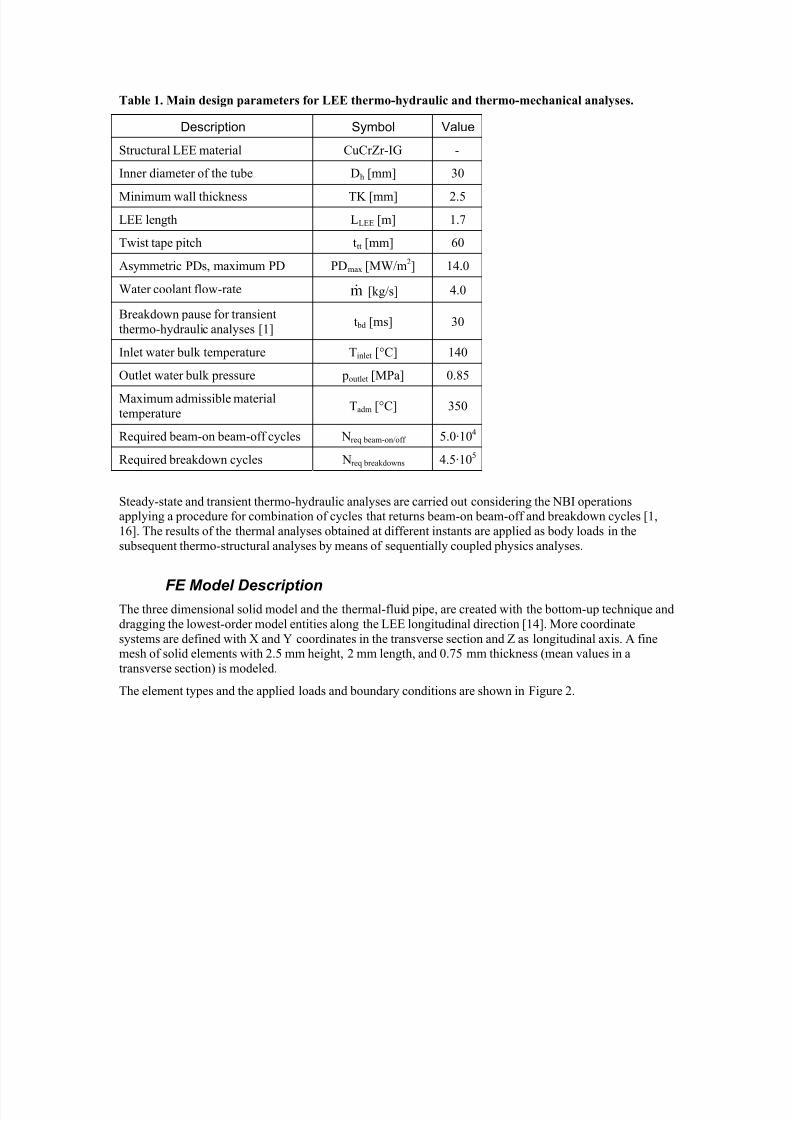
The local heat transfer coefficient is calculated in each iteration, once per element, and during each sub-step
of each load-step with the correlation:
αt for Ti ≤ Tsi αi =
αt + A·[(Ti – Ts)2.8
– (Tsi – Ts)2.8
]/(Ti – Tf ) for Ti > Tsi
Restrictions Concerning Cooling Conditions
The following hypotheses are to be satisfied because of the analytical model, matches on experimental data,well simulates the heat transfer phenomenon in flow boiling conditions [6]:
A. no bulk boiling in coolant flow, i.e. water mass-average temperature doesn’t exceed saturation
point at the tube exit;
B. stable heat removal in each tube cross-section, i.e. heat flux at the tube inner (cooling channel)surface doesn’t exceed critical value.
Nucleate Boiling Instabilities
As considered in a previously section, the fluid would be under-cooled at the inlet, and the heat transferwould happen by single-phase convection. The nucleate boiling (2) is present only if the heat flux exceeds
the limit value for the bubbles nucleation, then the over-heating of the liquid near the wall surface issufficient to start-up the bubbles nucleation. The heat transfer is high due to the transport of latent heat in
the vapor phase that grows at the wall surface. If the heat flux is insufficient to sustain this condition, the
inner tube wall temperature decreases, the heat flux decreases and the nucleate boiling condition would not
be satisfied (heat transfer by convective boiling mechanism 1). The reduced heat flux increases the wall
temperature, and then the heat flux rises and the nucleate boiling condition would be satisfied with bubblesnucleation.
These variations in the prevalent mechanism of heat transfer are observed as instabilities in the simulation
of the phenomena during the solution process between an iteration and the previous one of the thermo-hydraulic analyses. For this reason a special damping function is looked for to stabilize the heat transfer
phenomena at the inner wall surface. The fluctuations are mitigates by means of the special function
modifying the exchanged heat fluxes at two subsequent iterations. The motive-force of the exchanged heatflux, the difference between the inner wall tube temperature and the bulk temperature, is modified by the
special function calculating the mean value of wall temperature between the current iteration and the previous one for each surface element. The effect of this special function called by the customized routine
is to reduce significantly, at least one order of magnitude, the number of iterations to convergence.
User Programmable Routine Customization
The calculation of the heat transfer coefficient in flow boiling conditions in thermo-hydraulic analyses is
carried out compiling and relinking the user programmable routine “usrsurf116” in the ANSYS code. The
surface elements of the model “surf152” call this routine indirectly and the convection surface informationis changed applying the formulae introduced in previous sections of this work. The call to get the standard
ANSYS input convection surfaces is made just before entering this routine, so this information is available
to be modified. The heat transfer coefficient is function of heat flux, surface and coolant temperatures,water saturation curve [13], fluid dynamic properties of coolant, twist tape pitch, and location, and it is
calculated during each equilibrium iteration and during each sub-step of each load-step for each element.The extra nodes of “surf152” surface elements must be the same of the “fluid116” bulk elements to allow
passing of information. The element types used in the model are described in the next section.
The properties and variables of the model are passed through the formal arguments of the routine and otherquantities are brought in by “getv116” and “ndspgt” routines. The output argument of “getv116” routine
named omega of fluid node, is utilized to pass the twist tape pitch (in the form of angular velocity v·2·π·/ttt

8/13/2019 2006 Int Ansys Conf 40
http://slidepdf.com/reader/full/2006-int-ansys-conf-40 7/19
8/13/2019 2006 Int Ansys Conf 40
http://slidepdf.com/reader/full/2006-int-ansys-conf-40 8/19
8/13/2019 2006 Int Ansys Conf 40
http://slidepdf.com/reader/full/2006-int-ansys-conf-40 9/19
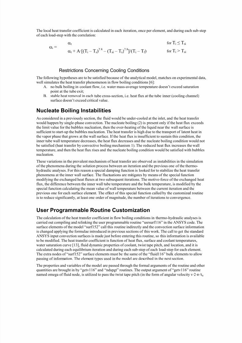
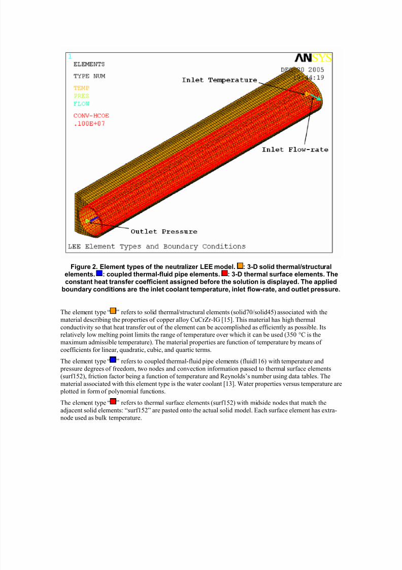
Figure 2. Element types of the neutralizer LEE model. : 3-D solid thermal/structuralelements. : coupled thermal-fluid pipe elements. : 3-D thermal surface elements. Theconstant heat transfer coefficient assigned before the solution is displayed. The applied
boundary conditions are the inlet coolant temperature, inlet flow-rate, and outlet pressure.
The element type “ ” refers to solid thermal/structural elements (solid70/solid45) associated with the
material describing the properties of copper alloy CuCrZr-IG [15]. This material has high thermal
conductivity so that heat transfer out of the element can be accomplished as efficiently as possible. Itsrelatively low melting point limits the range of temperature over which it can be used (350 °C is the
maximum admissible temperature). The material properties are function of temperature by means of
coefficients for linear, quadratic, cubic, and quartic terms.
The element type “ ” refers to coupled thermal-fluid pipe elements (fluid116) with temperature and pressure degrees of freedom, two nodes and convection information passed to thermal surface elements
(surf152), friction factor being a function of temperature and Reynolds’s number using data tables. The
material associated with this element type is the water coolant [13]. Water properties versus temperature are
plotted in form of polynomial functions.
The element type “ ” refers to thermal surface elements (surf152) with midside nodes that match the
adjacent solid elements: “surf152” are pasted onto the actual solid model. Each surface element has extra-node used as bulk temperature.
8/13/2019 2006 Int Ansys Conf 40
http://slidepdf.com/reader/full/2006-int-ansys-conf-40 10/19
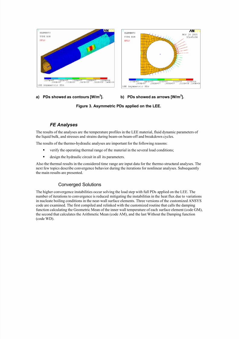
a) PDs showed as contours [W/m2]. b) PDs showed as arrows [W/m
2].
Figure 3. Asymmetric PDs applied on the LEE.
FE Analyses
The results of the analyses are the temperature profiles in the LEE material, fluid dynamic parameters of
the liquid bulk, and stresses and strains during beam-on beam-off and breakdown cycles.
The results of the thermo-hydraulic analyses are important for the following reasons:
verify the operating thermal range of the material in the several load conditions;
design the hydraulic circuit in all its parameters.
Also the thermal results in the considered time range are input data for the thermo-structural analyses. Thenext few topics describe convergence behavior during the iterations for nonlinear analyses. Subsequently
the main results are presented.
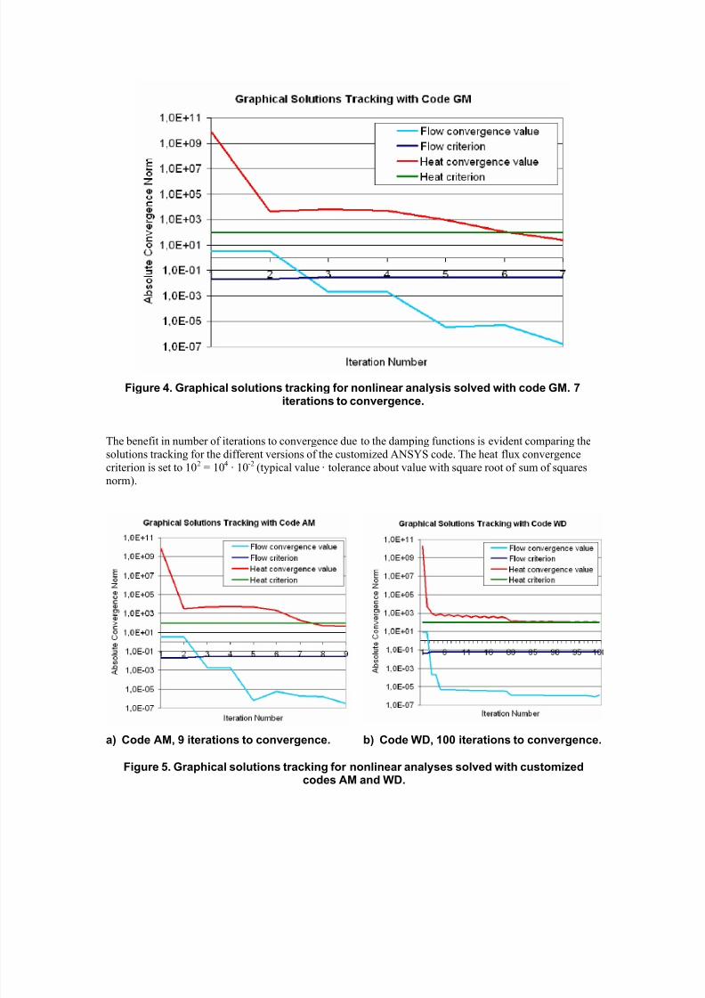
Converged Solutions
The higher convergence instabilities occur solving the load step with full PDs applied on the LEE. The
number of iterations to convergence is reduced mitigating the instabilities in the heat flux due to variations
in nucleate boiling conditions in the near-wall surface elements. Three versions of the customized ANSYScode are examined. The first compiled and relinked with the customized routine that calls the damping
function calculating the Geometric Mean of the inner wall temperature of each surface element (code GM),
the second that calculates the Arithmetic Mean (code AM), and the last Without the Damping function(code WD).
8/13/2019 2006 Int Ansys Conf 40
http://slidepdf.com/reader/full/2006-int-ansys-conf-40 11/19
Figure 4. Graphical solutions tracking for nonlinear analysis solved with code GM. 7iterations to convergence.
The benefit in number of iterations to convergence due to the damping functions is evident comparing the
solutions tracking for the different versions of the customized ANSYS code. The heat flux convergence
criterion is set to 102 = 104 · 10-2 (typical value · tolerance about value with square root of sum of squares
norm).
a) Code AM, 9 iterations to convergence. b) Code WD, 100 iterations to convergence.
Figure 5. Graphical solutions tracking for nonlinear analyses solved with customizedcodes AM and WD.
8/13/2019 2006 Int Ansys Conf 40
http://slidepdf.com/reader/full/2006-int-ansys-conf-40 12/19
The code WD is not successful to reach convergence with the assigned coolant flow-rate kg/s4.0m =&
that is necessary to exhaust the heat flux with 22/16 = 1.4 safety factor (CHF and maximum heat flux at the
inner channel surface ratio). The heat flux variations between two subsequent iterations are reduced
increasing the flow-rate to forbid the nucleate boiling phenomenon where the heat flux is insufficient to
maintain the nucleate boiling conditions. The increased flow-rate restricts the nucleate boiling in thesurface elements in steady-state conditions. The convergence is reached increasing the flow-rate up to
kg/s9.15m =&. The number of iterations to convergence is icode WD = 100 with flow-rate
kg/s9.15m =& , icode WD = 152 with flow-rate kg/s9.1m =& , icode WD greater than 200 with flow-rate
kg/s9.0m =& .
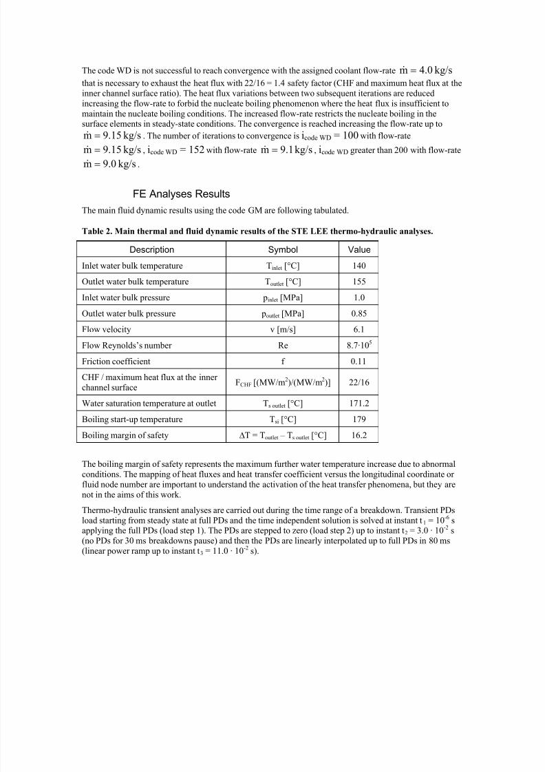
FE Analyses Results
The main fluid dynamic results using the code GM are following tabulated.
Table 2. Main thermal and fluid dynamic results of the STE LEE thermo-hydraulic analyses.
Description Symbol Value
Inlet water bulk temperature Tinlet
[°C] 140
Outlet water bulk temperature Toutlet [°C] 155
Inlet water bulk pressure pinlet [MPa] 1.0
Outlet water bulk pressure poutlet [MPa] 0.85
Flow velocity v [m/s] 6.1
Flow Reynolds’s number Re 8.7·105
Friction coefficient f 0.11
CHF / maximum heat flux at the inner
channel surfaceFCHF [(MW/m2)/(MW/m2)] 22/16
Water saturation temperature at outlet Ts outlet [°C] 171.2Boiling start-up temperature Tsi [°C] 179
Boiling margin of safety ∆T = Toutlet – Ts outlet [°C] 16.2
The boiling margin of safety represents the maximum further water temperature increase due to abnormal
conditions. The mapping of heat fluxes and heat transfer coefficient versus the longitudinal coordinate or
fluid node number are important to understand the activation of the heat transfer phenomena, but they are
not in the aims of this work.
Thermo-hydraulic transient analyses are carried out during the time range of a breakdown. Transient PDs
load starting from steady state at full PDs and the time independent solution is solved at instant t1 = 10-6 sapplying the full PDs (load step 1). The PDs are stepped to zero (load step 2) up to instant t2 = 3.0 · 10-2 s
(no PDs for 30 ms breakdowns pause) and then the PDs are linearly interpolated up to full PDs in 80 ms(linear power ramp up to instant t3 = 11.0 · 10-2 s).
8/13/2019 2006 Int Ansys Conf 40
http://slidepdf.com/reader/full/2006-int-ansys-conf-40 13/19
a) Maximum PD and node temperatureversus time during a breakdown.
b) Temperatures of nodes 321 and 319versus time during a breakdown.
Figure 6. Breakdowns transient analysis with 30 ms pause. Temperatures of the nodes321 and 319 situated in the middle plane of LEE with Z321 = 0.695 m and Z319 = 0.690 m.
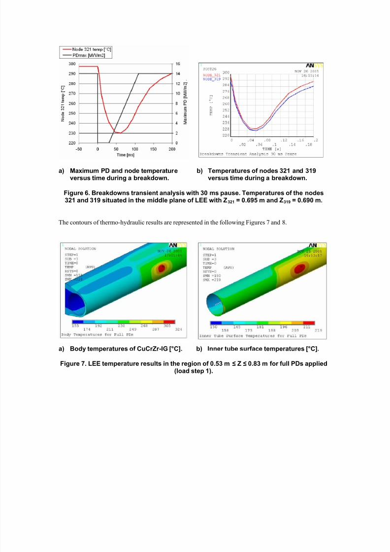
The contours of thermo-hydraulic results are represented in the following Figures 7 and 8.
a) Body temperatures of CuCrZr-IG [°C]. b) Inner tube surface temperatures [°C].
Figure 7. LEE temperature results in the region of 0.53 m ≤ Z ≤ 0.83 m for full PDs applied(load step 1).
8/13/2019 2006 Int Ansys Conf 40
http://slidepdf.com/reader/full/2006-int-ansys-conf-40 14/19
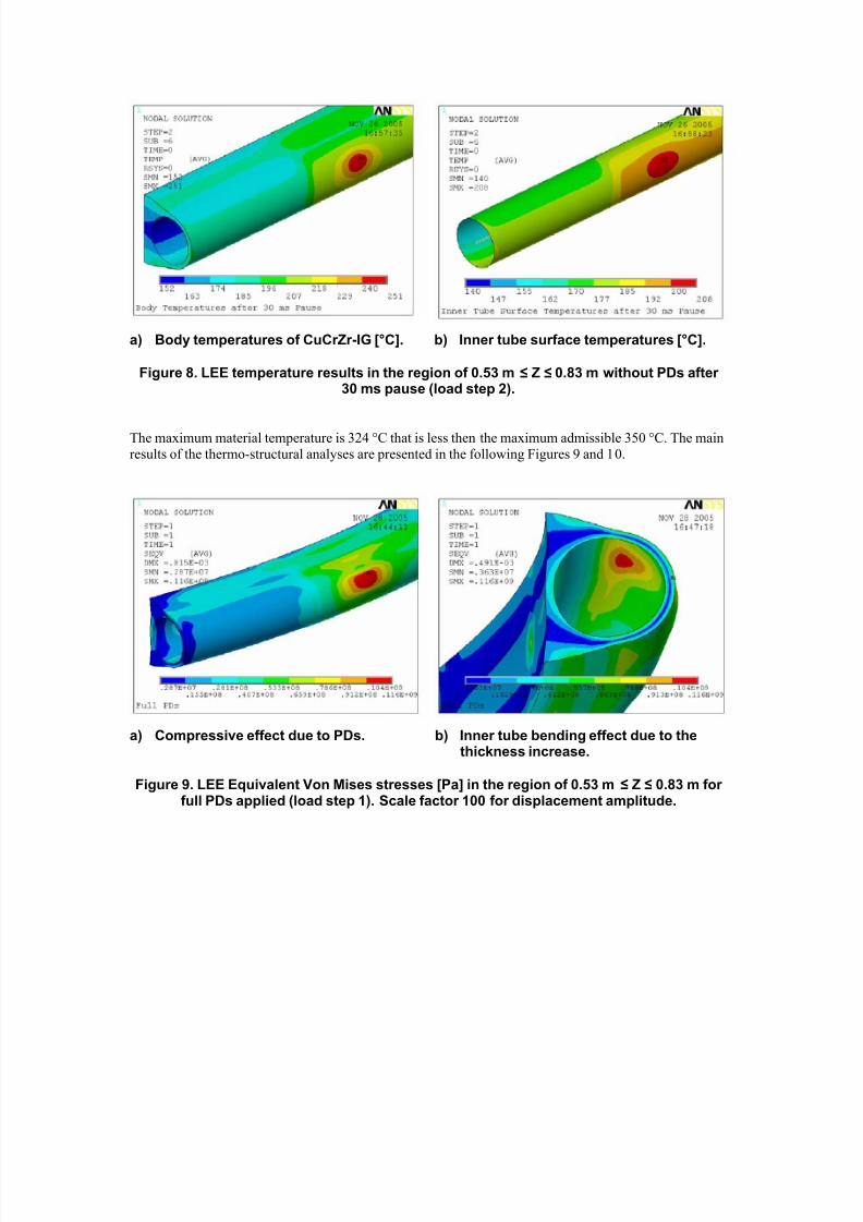
a) Body temperatures of CuCrZr-IG [°C]. b) Inner tube surface temperatures [°C].
Figure 8. LEE temperature results in the region of 0.53 m ≤ Z ≤ 0.83 m without PDs after30 ms pause (load step 2).
The maximum material temperature is 324 °C that is less then the maximum admissible 350 °C. The main
results of the thermo-structural analyses are presented in the following Figures 9 and 10.
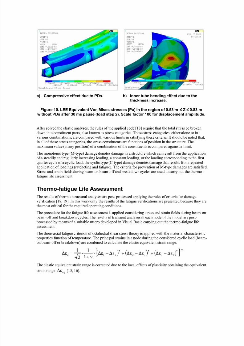
a) Compressive effect due to PDs. b) Inner tube bending effect due to thethickness increase.
Figure 9. LEE Equivalent Von Mises stresses [Pa] in the region of 0.53 m ≤ Z ≤ 0.83 m forfull PDs applied (load step 1). Scale factor 100 for displacement amplitude.
8/13/2019 2006 Int Ansys Conf 40
http://slidepdf.com/reader/full/2006-int-ansys-conf-40 15/19
a) Compressive effect due to PDs. b) Inner tube bending effect due to thethickness increase.
Figure 10. LEE Equivalent Von Mises stresses [Pa] in the region of 0.53 m ≤ Z ≤ 0.83 mwithout PDs after 30 ms pause (load step 2). Scale factor 100 for displacement amplitude.
After solved the elastic analyses, the rules of the applied code [18] require that the total stress be broken
down into constituent parts, also known as stress categories. These stress categories, either alone or invarious combinations, are compared with various limits in satisfying these criteria. It should be noted that,
in all of these stress categories, the stress constituents are functions of position in the structure. The
maximum value (at any position) of a combination of the constituents is compared against a limit.
The monotonic type (M-type) damage denotes damage in a structure which can result from the application
of a steadily and regularly increasing loading, a constant loading, or the loading corresponding to the first
quarter cycle of a cyclic load; the cyclic type (C-type) damage denotes damage that results from repeated
application of loadings (ratcheting and fatigue). The criteria for prevention of M-type damages are satisfied.
Stress and strain fields during beam-on beam-off and breakdown cycles are used to carry out the thermo-fatigue life assessment.
Thermo-fatigue Life Assessment
The results of thermo-structural analyses are post-processed applying the rules of criteria for damageverification [18, 19]. In this work only the results of the fatigue verifications are presented because they are
the most critical for the required operating conditions.
The procedure for the fatigue life assessment is applied considering stress and strain fields during beam-on
beam-off and breakdown cycles. The results of transient analyses in each node of the model are post-
processed by means of a suitable macro developed in Visual Basic carrying out the thermo-fatigue lifeassessment.
The three-axial fatigue criterion of octahedral shear stress theory is applied with the material characteristic
properties function of temperature. The principal strains in a node during the considered cyclic load (beam-
on beam-off or breakdown) are combined to calculate the elastic equivalent strain range:
( ) ( ) ( )[ ]1/22
13
2
32
2
21el εεεεεε ν1
1
2
1ε −+−+−⋅
+⋅=
The elastic equivalent strain range is corrected due to the local effects of plasticity obtaining the equivalent
strain range eqε [15, 16].
8/13/2019 2006 Int Ansys Conf 40
http://slidepdf.com/reader/full/2006-int-ansys-conf-40 16/19
The effects of the mean strain on the fatigue design curve are taken into account drawing the local Haigh
diagram for each node [20]. The calculation of the equivalent mean strain in value and sign, and the
construction of the Haigh diagram and the fatigue design curve in each node are left out because they are
not in the aims of this work. The main results are represented in the following Figures 11, 12, 13, and Table
3.
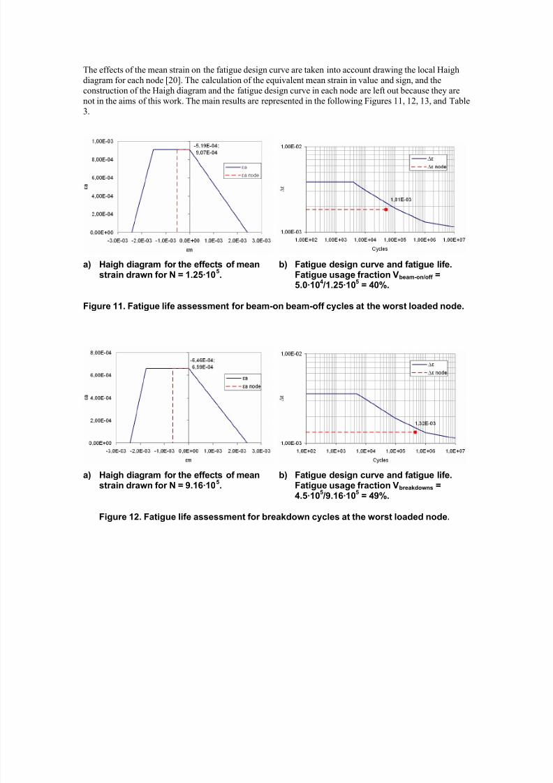
a) Haigh diagram for the effects of mean
strain drawn for N = 1.25·105.
b) Fatigue design curve and fatigue life.
Fatigue usage fraction Vbeam-on/off =5.0·10
4 /1.25·10
5 = 40%.
Figure 11. Fatigue life assessment for beam-on beam-off cycles at the worst loaded node.
a) Haigh diagram for the effects of meanstrain drawn for N = 9.16·10
5.
b) Fatigue design curve and fatigue life.Fatigue usage fraction Vbreakdowns =4.5·10
5 /9.16·10
5 = 49%.
Figure 12. Fatigue life assessment for breakdown cycles at the worst loaded node.
8/13/2019 2006 Int Ansys Conf 40
http://slidepdf.com/reader/full/2006-int-ansys-conf-40 17/19
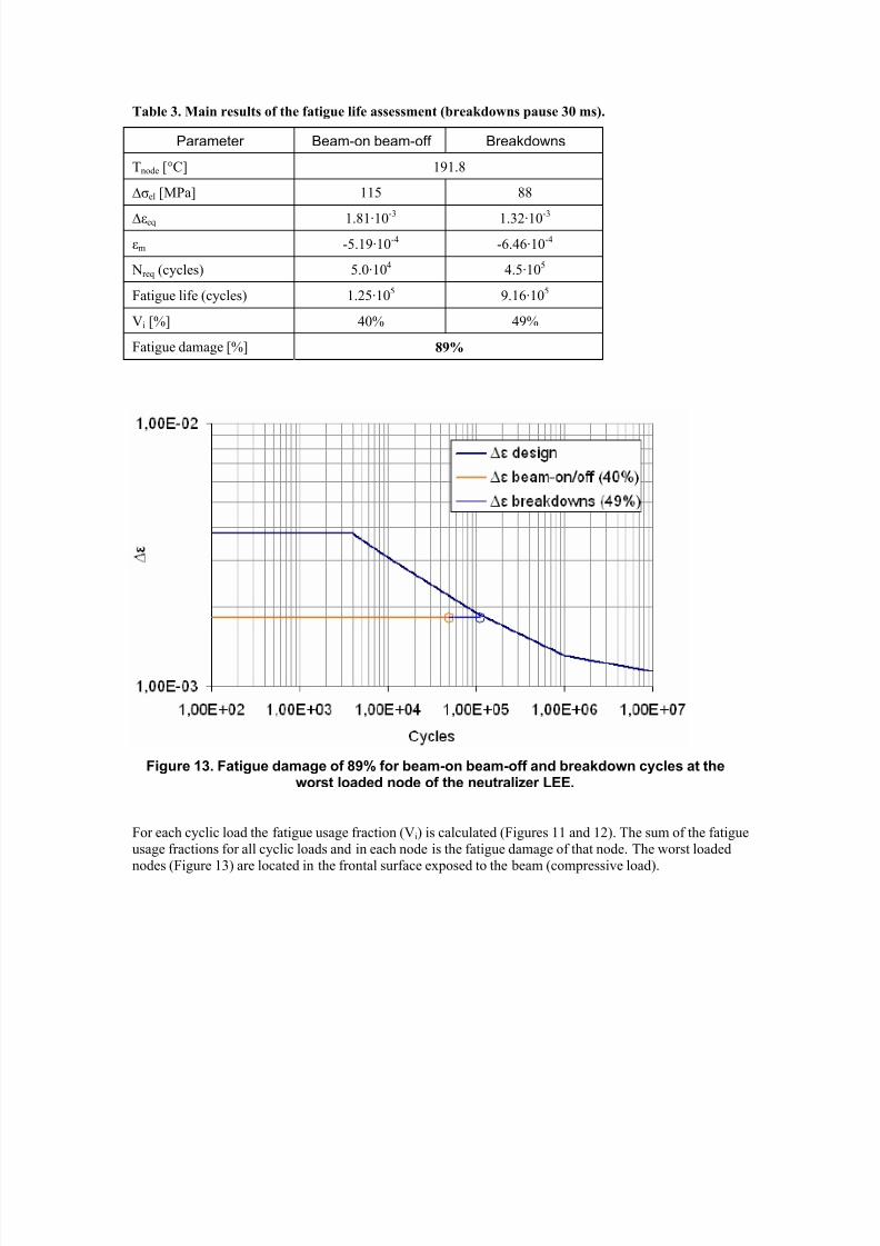
Table 3. Main results of the fatigue life assessment (breakdowns pause 30 ms).
Parameter Beam-on beam-off Breakdowns
Tnode [°C] 191.8
∆σel [MPa] 115 88
∆εeq 1.81·10-3 1.32·10-3
εm -5.19·10-4 -6.46·10-4
Nreq (cycles) 5.0·104 4.5·105
Fatigue life (cycles) 1.25·105 9.16·105
Vi [%] 40% 49%
Fatigue damage [%] 89%
Figure 13. Fatigue damage of 89% for beam-on beam-off and breakdown cycles at theworst loaded node of the neutralizer LEE.
For each cyclic load the fatigue usage fraction (Vi) is calculated (Figures 11 and 12). The sum of the fatigue
usage fractions for all cyclic loads and in each node is the fatigue damage of that node. The worst loaded
nodes (Figure 13) are located in the frontal surface exposed to the beam (compressive load).
8/13/2019 2006 Int Ansys Conf 40
http://slidepdf.com/reader/full/2006-int-ansys-conf-40 18/19
Conclusions
The customized ANSYS code allows us to carry out coupled thermo-hydraulic and thermo-mechanicalanalyses of high heat flux components with swirl tube elements.
The damping function implemented in the user programmable routine, so named because it reduces the
fluctuation in heat flux between iteration and the previous one, allows to diminish at least one order ofmagnitude the number of iteration to convergence with reduced time of analysis. Furthermore, the damping
function is necessary to reach convergence solutions in the analysis where nucleate boiling conditions areforeseen in extended areas of the model. The only possibility to reach convergence in these analyses with
the assigned thermal loads and without using the damping function, is to increase the flow-rate to forbid the
nucleate boiling phenomenon where the heat flux is insufficient to maintain the nucleate boiling conditions.
In this way the increased flow-rate reduces the heat flux instabilities but it can be really improbable and thenumber of iterations to convergence becomes very high.
The customized routine compiled and re-linked in the ANSYS code is a general tool applicable to high heat
flux components in fusion technology. Dedicated neural networks that simulate heat exchange in swirl tube
elements or other devices as hypervapotrons, are possible reliable models that can be implemented in theANSYS customized code.
The results of coupled thermo-hydraulic and thermo-mechanical analyses of the ITER neutralizer centreleading edge using the customized ANSYS code are explained in this work. After solved the elastic
analyses, the rules of the applied design criteria require that the total stress be broken down into stress
categories.
The procedure for the fatigue life assessment is applied considering stress and strain fields during beam-on beam-off and breakdown cycles. The results of transient analyses in each node of the model are post-
processed by means of a suitable macro, developed in Visual Basic, carrying out the thermo-fatigue life
assessment: the three-axial fatigue criterion of octahedral shear stress theory is applied with the materialcharacteristic properties function of temperature, the elastic equivalent strain range is corrected due to the
local effects of plasticity in each node, the effects of the mean strain on the fatigue design curve are taken
into account drawing the local Haigh diagram in each node, the fatigue damage of each node is calculated
as sum of the fatigue usage fractions of that node.
The criteria for prevention of damages which can result from the application of constant loads on the
leading edge are satisfied, the maximum nodes temperature (324 °C) is less than the admissible (350 °C),and the thermo-fatigue verification is satisfied with 89% fatigue damage due to beam-on beam-off and
breakdown cycles.
References
1 ITER DDD5.3 Appendix 4, Thermohydraulic and Thermomechanical Analyses of the High Heat
Flux Beam Line Components, N 53 DDD 33 01-07-10 R 0.1.
2 ITER DDD5.3, Neutral Beam Heating and Current Drive (NBH&CD) System, N 53 DDD 29 01-
07-03 R 0.1.
3 Naumov V.K., Semashko N.N., Analytical Model for Estimating Thermophysical and Strength
Parameters of the Cooled Pipe with the Twisted Tape under Asymmetric Heating by a Pulse ofExternal Heat Flux, Plasma Devices and Operations, 1994, vol. 3, pp. 267-280.
4 Naumov V.K., Semashko N.N., Finite-difference Approximation of the Adiabatic Cross-section
Technique in a Numerical Analysis of the Single-side Heating Process of a Cooled Pipe with theTwisted Tape Inside by an External Heat Flux Pulse, Plasma Devices and Operations, 1995, vol. 4,
pp. 141-161.
5 Lopina R.F., Bergles A.E., Heat Transfer and Pressure Drop in Tape-Generated Swirl Flow of
Single-Phase Water, Transaction of the ASME, Journal of Heat Transfer, August 1969, pp. 434-
445.
8/13/2019 2006 Int Ansys Conf 40
http://slidepdf.com/reader/full/2006-int-ansys-conf-40 19/19
6 Naumov V.K. et.al., Method of Adiabatic Cross-section and its Application for Estimating of
Thermophysical and Thermostrength Parameters of High Density Beam Dumps in the ITER
Injection System, Plasma Devices and Operations, 1999, vol. 8, pp. 39-65.
7 Thom J.R.S., Walter W.M., Fallon T.A., Reising G.F.S., Symposium on Boiling Heat Transfer in
Steam Generating Units and Heat Exchangers, Manchester, 15-16 September 1965.
8 Kutateladze S.S., Fundamental Heat Exchange Theory, 5th edd., suppl. Atomizdat, Moscow, 1979.
9 Yagov V.V., Zudin Yu.B., Proceeding 10th International Heat Transfer Conference, 1994, vol. 5, pp. 189-194.
10 EU Home Team, Final Report on Task PDT 2-4, Thermal hydraulic test on divertor targets using
swirl tubes, CEA (Schlosser J., Boscary J.).
11 John H. Lienhard, A Heat Transfer Handbook Third Edition, Cambridge Massachusetts, January
2004.
12 Bergles A.E, Rohsenow W.M., Paper 63-HT-22, 6th National Heat Transfer Conference of theASME-AIChE, Boston, 11-14 August 1963.
13 SteamTab™ add-in software, Implementation of steam properties formulation approved by the
International Association for the Properties of Water and Steam (IAPWS): The IAPWS
Formulation of Ordinary Water for General and Scientific Use (IAPWS-95).
14 ANSYS Release 8.0 Documentation, Element Reference, Element Library.
15 ITER SDC-IC Appendix A, Materials Design Limit Data, G 74 MA 8 R0.1, July 2004.
16 ITER SDC-IC Appendix B, Guidelines for Analysis, In-vessel Components, G 74 MA 8 R0.1.
17 H.P.L. de Esch, ITER-SINGAP Full Geometry Simulations, June 2003 (CCNB meeting).
18 ITER SDC-IC, Structural Design Criteria for ITER In-Vessel Components, July 2004.
19 Criteria of the ASME Boiler and Pressure Vessel Code for Design by Analysis in Sections III and
VIII, Division 2, The American Society of Mechanical Engineers, United Engineering Center,
New York.
20 Papadopoulos I.V., Davoli P., Gorla C., Filippini M., Bernasconi A., A comparative study of
multiaxial high-cycle fatigue criteria for metals, International Journal of Fatigue, Vol. 19, Issue 3,March 1997, pp. 219-235.
Acknowledgment
This work, supported by the European Communities under the contract of Association between
EURATOM-ENEA, was carried out within the framework of the European Fusion DevelopmentAgreement. The views and opinions expressed herein do not necessarily reflect those of the European
Commission.