
2006 APWA International Congress & Exposition Kansas … · 1 INDEPENDENT ENVIRONMENTAL ENGINEERS,...
27
T.D. Stark Lecture – 9/13/06 © 1 LANDFILL STABILITY ISSUES Timothy D. Stark, Ph.D., P.E. University of Illinois at Urbana-Champaign 2006 APWA International Congress & Exposition Kansas City, Missouri T.D. Stark Lecture – 9/13/06 © 2 • Current Situation • Liner Failure Mechanisms • Cover Failure Mechanisms • Emerging Issues OUTLINE • Conclusions
-
Upload
phungthien -
Category
Documents
-
view
213 -
download
0
Transcript of 2006 APWA International Congress & Exposition Kansas … · 1 INDEPENDENT ENVIRONMENTAL ENGINEERS,...
T.D. Stark Lecture – 9/13/06 ©
1
LANDFILL STABILITY ISSUES
Timothy D. Stark, Ph.D., P.E.University of Illinois at Urbana-Champaign
2006 APWA International Congress & ExpositionKansas City, Missouri
T.D. Stark Lecture – 9/13/06 ©
2
• Current Situation
• Liner Failure Mechanisms
• Cover Failure Mechanisms
• Emerging Issues
OUTLINE
• Conclusions

T.D. Stark Lecture – 9/13/06 ©
3
CURRENT SITUATION
• MAJORITY OF LANDFILLS ARE CONSTRUCTEDAND OPERATED SAFELY
• STATE-OF-PRACTICE TESTING, DESIGN,AND ANALYSIS PROCEDURES
• NATURAL MATERIALS - 12
• GEOSYNTHETIC MATERIALS - 32
T.D. Stark Lecture – 9/13/06 ©
4
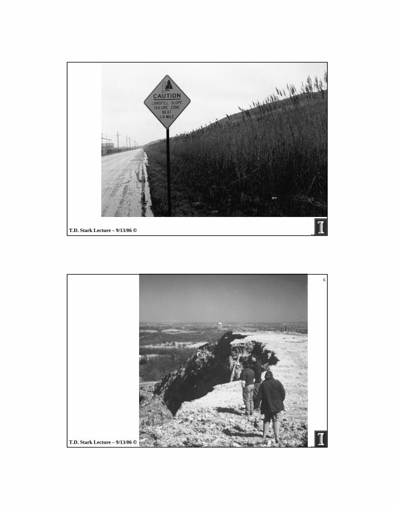
Death Toll = 216
(Merry 2005)
T.D. Stark Lecture – 9/13/06 ©
5
T.D. Stark Lecture – 9/13/06 ©
6
T.D. Stark Lecture – 9/13/06 ©
7
T.D. Stark Lecture – 9/13/06 ©
8
T.D. Stark Lecture – 9/13/06 ©
9
• Current Situation
• Liner Failure Mechanisms
• Cover Failure Mechanisms
• Emerging Issues
OUTLINE
• Conclusions
T.D. Stark Lecture – 9/13/06 ©
10
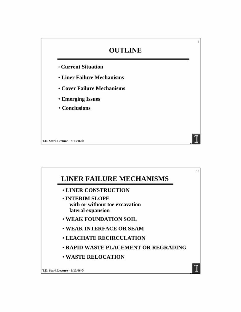
LINER FAILURE MECHANISMS
• INTERIM SLOPEwith or without toe excavationlateral expansion
• WEAK FOUNDATION SOIL
• WEAK INTERFACE OR SEAM
• LEACHATE RECIRCULATION
• LINER CONSTRUCTION
• RAPID WASTE PLACEMENT OR REGRADING
• WASTE RELOCATION
T.D. Stark Lecture – 9/13/06 ©
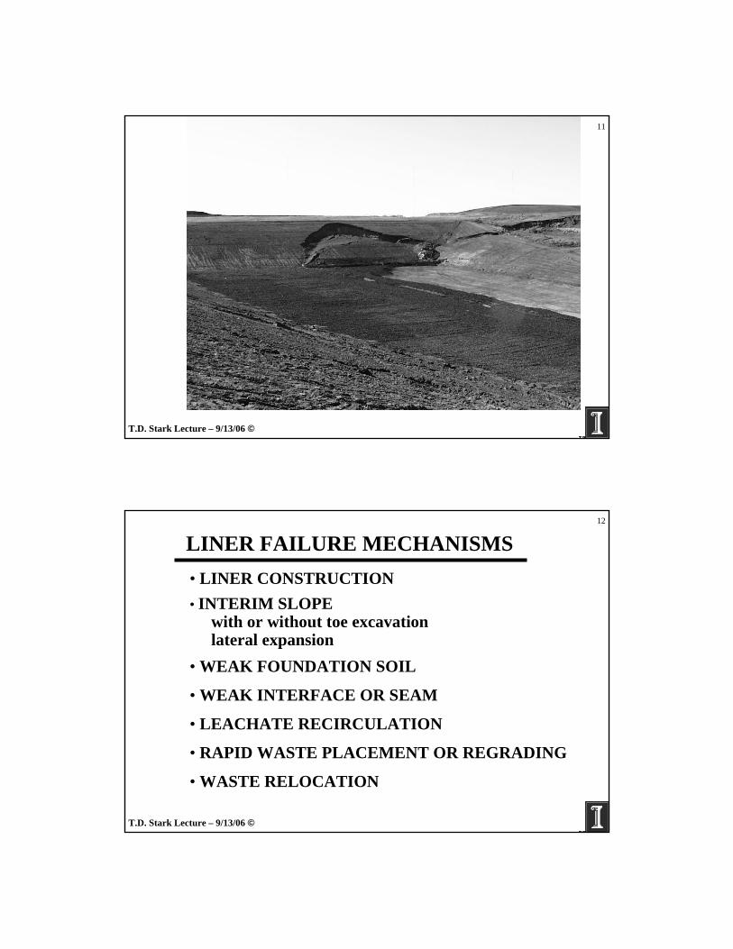
11
T.D. Stark Lecture – 9/13/06 ©
12
LINER FAILURE MECHANISMS
• INTERIM SLOPEwith or without toe excavationlateral expansion
• WEAK FOUNDATION SOIL
• WEAK INTERFACE OR SEAM
• LEACHATE RECIRCULATION
• LINER CONSTRUCTION
• RAPID WASTE PLACEMENT OR REGRADING
• WASTE RELOCATION

T.D. Stark Lecture – 9/13/06 ©
13
T.D. Stark Lecture – 9/13/06 ©
14
T.D. Stark Lecture – 9/13/06 ©
15
LINER FAILURE MECHANISMS
• INTERIM SLOPEwith or without toe excavationlateral expansion
• WEAK FOUNDATION SOIL
• WEAK SEAM OR INTERFACE
• LEACHATE RECIRCULATION
• LINER CONSTRUCTION
• RAPID WASTE PLACEMENT OR REGRADING
• WASTE RELOCATION
T.D. Stark Lecture – 9/13/06 ©
16
• Current Situation
• Liner Failure Mechanisms
• Cover Failure Mechanisms
• Emerging Issues
OUTLINE
• Conclusions

T.D. Stark Lecture – 9/13/06 ©
17
COVER FAILURE MECHANISMS
• RAINFALL/SEEPAGE-INDUCED• GAS OR LEACHATE-INDUCED • GCLs (?)
Replace woven geotextileFlip GCL over
• WEAK INTERFACE
T.D. Stark Lecture – 9/13/06 ©
18
T.D. Stark Lecture – 9/13/06 ©
19
• Current Situation
• Liner Failure Mechanisms
• Cover Failure Mechanisms
• Emerging Issues
OUTLINE
• Conclusions
T.D. Stark Lecture – 9/13/06 ©
20
EMERGING/TROUBLING ISSUES• LACK OF DESIGN
- Recycling designs- Use of peak instead of residual strength- Not locating critical cross-section

T.D. Stark Lecture – 9/13/06 ©
21Critical Cross-Section
T.D. Stark Lecture – 9/13/06 ©
22
EMERGING/TROUBLING ISSUES
• INADEQUATE TESTING- Soils & geosynthetics- Data recycled from prior site- Full range of normal stress
T.D. Stark Lecture – 9/13/06 ©
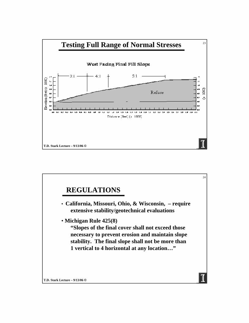
23Testing Full Range of Normal Stresses
T.D. Stark Lecture – 9/13/06 ©
24
REGULATIONS
• California, Missouri, Ohio, & Wisconsin, – require extensive stability/geotechnical evaluations
• Michigan Rule 425(8)“Slopes of the final cover shall not exceed thosenecessary to prevent erosion and maintain slopestability. The final slope shall not be more than1 vertical to 4 horizontal at any location…”
T.D. Stark Lecture – 9/13/06 ©
25
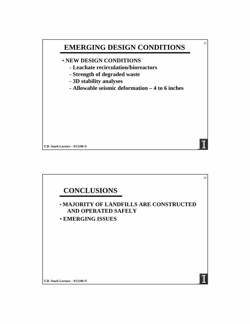
EMERGING DESIGN CONDITIONS
• NEW DESIGN CONDITIONS- Leachate recirculation/bioreactors- Strength of degraded waste- 3D stability analyses- Allowable seismic deformation – 4 to 6 inches
T.D. Stark Lecture – 9/13/06 ©
26
CONCLUSIONS
• MAJORITY OF LANDFILLS ARE CONSTRUCTEDAND OPERATED SAFELY
• EMERGING ISSUES

T.D. Stark Lecture – 9/13/06 ©
27
Questions & Comments are
Welcome
T.D. Stark Lecture – 9/13/06 ©
28
Speaker Information:
• Timothy Stark, Ph.D., P.E.– Professor of Civil and Environmental Engineering– University of Illinois at Urbana-Champaign– 205 N. Mathews Ave.
Urbana, IL 61801– 217-333-7394– [email protected]
1
INDEPENDENT ENVIRONMENTAL ENGINEERS, SCIENTISTS AND CONSULTANTS
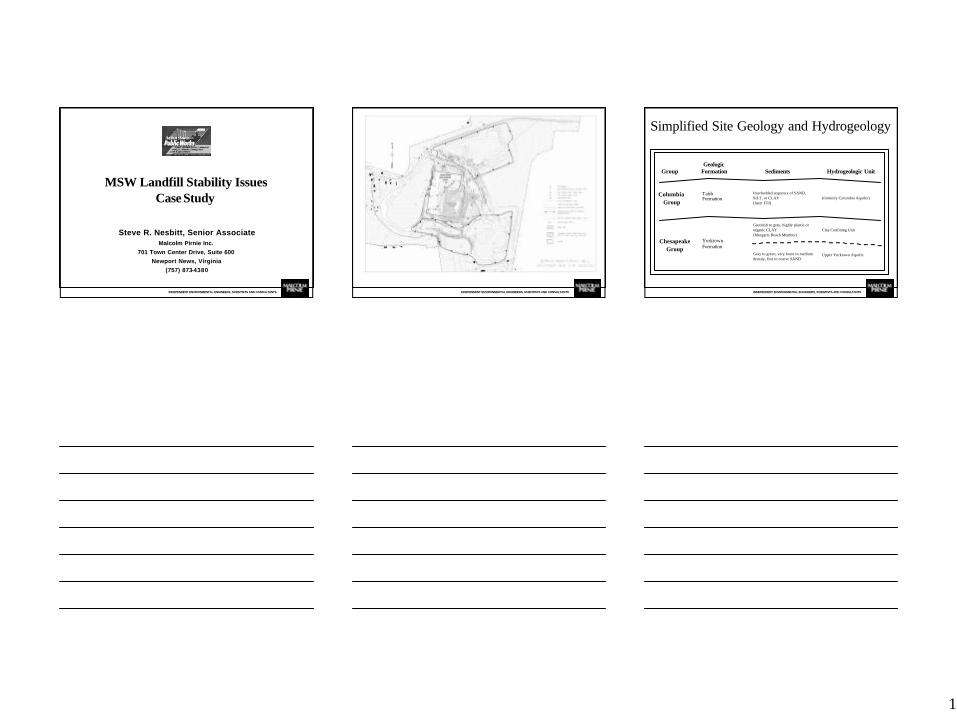
Steve R. Nesbitt, Senior AssociateMalcolm Pirnie Inc.
701 Town Center Drive, Suite 600Newport News, Virginia
(757) 873-4380
MSW Landfill Stability Issues Case Study
INDEPENDENT ENVIRONMENTAL ENGINEERS, SCIENTISTS AND CONSULTANTS INDEPENDENT ENVIRONMENTAL ENGINEERS, SCIENTISTS AND CONSULTANTS
Group
Columbia Group
Chesapeake Group
Tabb Formation
Yorktown Formation
Interbedded sequence of SAND, SILT, or CLAY (Inert Fill)
Greenish to gray, highly plastic or organic CLAY (Morgarts Beach Member)
Gray to green, very loose to medium density, fine to coarse SAND
(formerly Columbia Aquifer)
Clay Confining Unit
Upper Yorktown Aquifer
Geologic Formation Sediments Hydrogeologic Unit
Simplified Site Geology and Hydrogeology
2
INDEPENDENT ENVIRONMENTAL ENGINEERS, SCIENTISTS AND CONSULTANTS
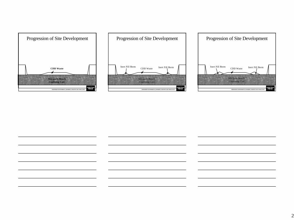
Morgarts Beach Confining Unit
CDD Waste
Progression of Site Development
INDEPENDENT ENVIRONMENTAL ENGINEERS, SCIENTISTS AND CONSULTANTS
Morgarts Beach Confining Unit
CDD WasteInert Fill Berm Inert Fill Berm
Progression of Site Development
INDEPENDENT ENVIRONMENTAL ENGINEERS, SCIENTISTS AND CONSULTANTS
CDD WasteInert Fill Berm Inert Fill Berm
Morgarts Beach Confining Unit
Progression of Site Development
3
INDEPENDENT ENVIRONMENTAL ENGINEERS, SCIENTISTS AND CONSULTANTS
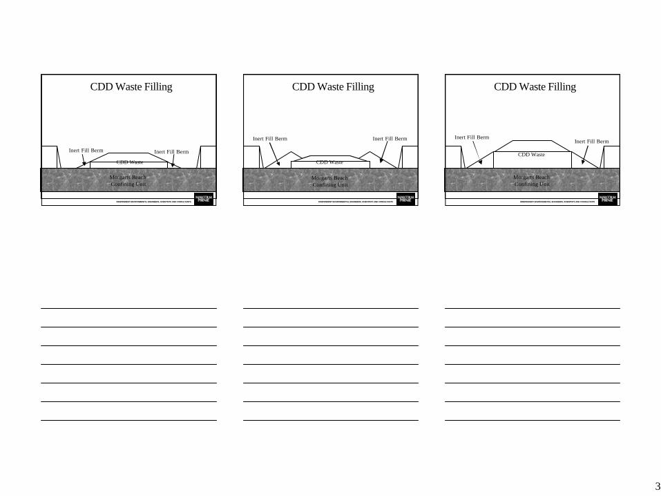
Inert Fill Berm Inert Fill Berm
CDD Waste
Morgarts Beach Confining Unit
CDD Waste Filling
INDEPENDENT ENVIRONMENTAL ENGINEERS, SCIENTISTS AND CONSULTANTS
Inert Fill Berm Inert Fill Berm
CDD Waste
Morgarts Beach Confining Unit
CDD Waste Filling
INDEPENDENT ENVIRONMENTAL ENGINEERS, SCIENTISTS AND CONSULTANTS
Inert Fill BermInert Fill Berm
CDD Waste
CDD Waste Filling
Morgarts Beach Confining Unit

4
INDEPENDENT ENVIRONMENTAL ENGINEERS, SCIENTISTS AND CONSULTANTS
Inert Fill BermInert Fill Berm
CDD Waste
CDD Waste Filling
Morgarts Beach Confining Unit
INDEPENDENT ENVIRONMENTAL ENGINEERS, SCIENTISTS AND CONSULTANTS
CDD Waste Filling
Morgarts Beach Confining Unit
Inert Fill Berm Inert Fill Berm
CDD Waste
INDEPENDENT ENVIRONMENTAL ENGINEERS, SCIENTISTS AND CONSULTANTS
Inert Fill Berm Inert Fill Berm
CDD Waste
CDD Waste Filling
Morgarts Beach Confining Unit

5
INDEPENDENT ENVIRONMENTAL ENGINEERS, SCIENTISTS AND CONSULTANTS
CDD Waste
Inert Fill Berm Inert Fill Berm
CDD Waste Filling
Morgarts Beach Confining Unit
INDEPENDENT ENVIRONMENTAL ENGINEERS, SCIENTISTS AND CONSULTANTS
Inert Fill Berm Inert Fill Berm
CDD Waste
CDD Waste Filling
Morgarts Beach Confining Unit
INDEPENDENT ENVIRONMENTAL ENGINEERS, SCIENTISTS AND CONSULTANTS
Inert Fill Berm Inert Fill Berm
CDD Waste
CDD Waste Filling
Morgarts Beach Confining Unit

6
INDEPENDENT ENVIRONMENTAL ENGINEERS, SCIENTISTS AND CONSULTANTS INDEPENDENT ENVIRONMENTAL ENGINEERS, SCIENTISTS AND CONSULTANTS INDEPENDENT ENVIRONMENTAL ENGINEERS, SCIENTISTS AND CONSULTANTS INDEPENDENT ENVIRONMENTAL ENGINEERS, SCIENTISTS AND CONSULTANTS
Typical Cross Section
7
INDEPENDENT ENVIRONMENTAL ENGINEERS, SCIENTISTS AND CONSULTANTS
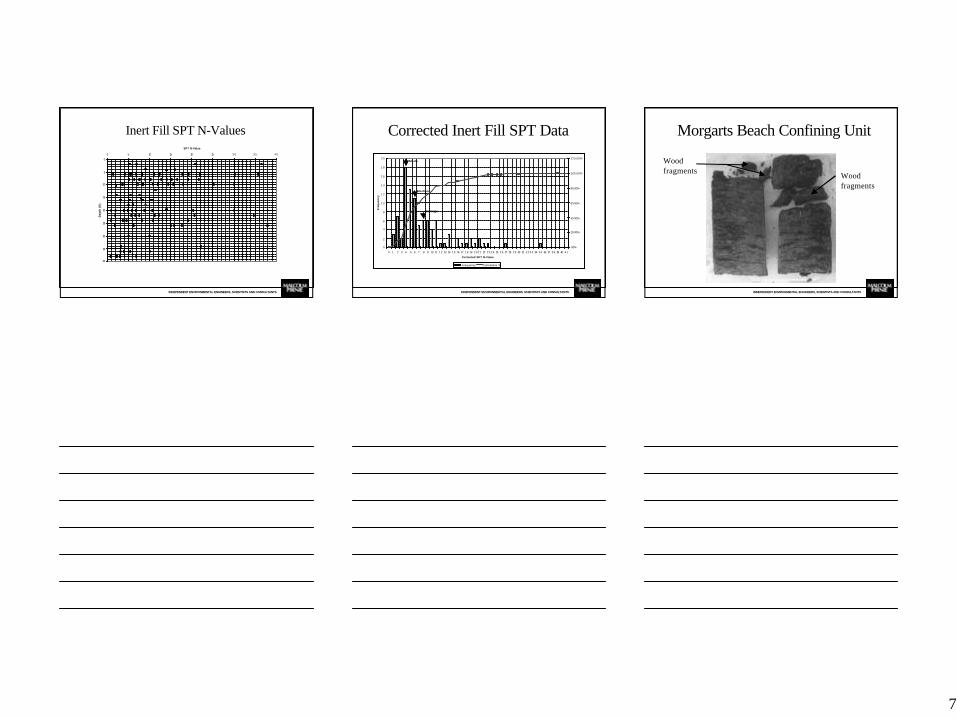
Inert Fill SPT N-Values
0
5
10
15
20
25
30
35
40
0 5 10 15 20 25 3 0 3 5 4 0
SPT N-Value
Dep
th (
ft)
INDEPENDENT ENVIRONMENTAL ENGINEERS, SCIENTISTS AND CONSULTANTS
Corrected Inert Fill SPT Data
0
2
4
6
8
1 0
1 2
1 4
1 6
1 8
2 0
0 1 2 3 4 5 6 7 8 9 10 11 1 2 13 14 1 5 16 17 1 8 19 2 0 2 1 22 2 3 2 4 25 2 6 27 28 2 9 30 31 3 2 3 3 34 3 5 36 37 3 8 39 40 4 1
Corrected SPT N-Value
Fre
qu
ency
.00%
20.00%
40.00%
60.00%
80.00%
100.00%
120.00%
Frequency Cumulative %
Mode
Median
Average
INDEPENDENT ENVIRONMENTAL ENGINEERS, SCIENTISTS AND CONSULTANTS
Wood fragments
Wood fragments
Morgarts Beach Confining Unit
8
INDEPENDENT ENVIRONMENTAL ENGINEERS, SCIENTISTS AND CONSULTANTS
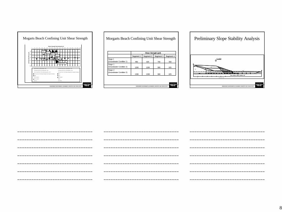
Mogarts Beach Confining Unit Shear Strength
0
1000
2000
3000
4000
5000
6000
0 100 200 300 400 500 600 700 800 900 1000 1100 1200 1300 1400 1500 1600 1700 1800 1900
Shear Strength (Undrained), psf
Ove
rbu
rden
Str
ess,
psf
B13 (Sur. Elev. 10.3 ft)-UU-Elev. -39 ft Field Vane (Sur. Elev. 10.3)-B13-Elev. -23 ft
Field Vane (Sur. Elev. 10.3 ft)-B13-Elev. -25 ft Field Vane (Sur. Elev. 10.3 ft)-B13-Elev. -28 ft
B12-CU (Sur Elev. 9.75 ft) (Total Stress)-Elev. -35 ft B13 (Sur. Elev. 10.3 ft) Shear Strenghts from Empirical Correlation
B12 (Sur. Elev. 9.75 ft) Shear Strengths from Empirical Correlation B7-UU
B8-UU B4-UU
B7-Correlated B8-Correlated
B4-Correlated B3-CU
B1-A-CU Direct Shear
Segment 1(Stage 1)
Segment 3(Stage 1)
Segment 4(Stage 1)
Segment 2(Stage 1)
Estimated 'trend -line'
INDEPENDENT ENVIRONMENTAL ENGINEERS, SCIENTISTS AND CONSULTANTS
Morgarts Beach Confining Unit Shear Strength
62590012001200
Stage 2(Groundwater Condition 2)
62590012001200
Stage 1(Groundwater Condition 2)
550700825950Stage 1 (Groundwater Condition 1)
Segment 4Segment 3Segment 2Segment 1
Shear Strength (psf)
INDEPENDENT ENVIRONMENTAL ENGINEERS, SCIENTISTS AND CONSULTANTS
0.468
CDD
York town Sand
Inert Fill
Layer 3
El. 136El. 140
E l . 2 0
Layer 1
5 %
3 H : 1 V
E l . 1 0E l . 4
El. 120
Layer 2 Layer 4
Pond
Additional
Berm
CDDCDD
Distance (ft) (x 1000)0.0 0.1 0.2 0.3 0.4 0.5 0.6 0.7 0.8 0.9 1.0 1.1 1.2
Preliminary Slope Stability Analysis

9
INDEPENDENT ENVIRONMENTAL ENGINEERS, SCIENTISTS AND CONSULTANTS
Staged Development
Stage 1 Pond Filling
Stage 1 Waste Filling
Stage 2 Pond Filling
Stage 2 Waste Filling Existing CDD Waste
Existing Inert Fill
Groundwater Condition 1 (Active Dewatering)
Groundwater Condition 2 (Post-Dewatering)
Morgart ’s Beach Clay
INDEPENDENT ENVIRONMENTAL ENGINEERS, SCIENTISTS AND CONSULTANTS
Landfill Stability Factors of Safety
1.7531.5881.3491.201Stage 2 (Groundwater Condition 2)
1.9251.7911.4251.254Stage 2(Groundwater Condition 1)
2.0461.6871.5001.203Stage 1(Groundwater Condition 2)
2.3612.1231.6581.266Stage 1(Groundwater Condition 1)
CircularBlockCircularBlock
Effective Stress AnalysisTotal Stress Analysis
Factor of Safety
Stage and Water Table Level
INDEPENDENT ENVIRONMENTAL ENGINEERS, SCIENTISTS AND CONSULTANTS
Mogarts Beach Confining Unit Structure Map
10
INDEPENDENT ENVIRONMENTAL ENGINEERS, SCIENTISTS AND CONSULTANTS
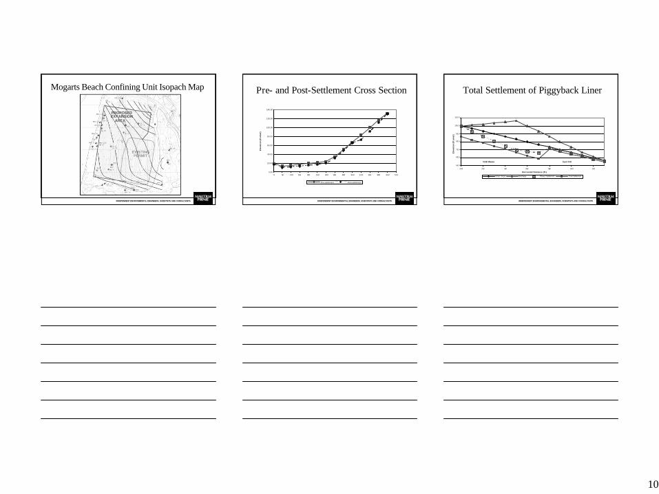
Mogarts Beach Confining Unit Isopach Map
INDEPENDENT ENVIRONMENTAL ENGINEERS, SCIENTISTS AND CONSULTANTS
Pre- and Post-Settlement Cross Section
0.00
20.00
40.00
60.00
80.00
100.00
120.00
140.00
0 50 100 150 200 250 300 350 400 450 500 550 600 650 700
Pre-settlement Post-settlement
Ele
va
tio
n (f
t am
sl)
INDEPENDENT ENVIRONMENTAL ENGINEERS, SCIENTISTS AND CONSULTANTS
Total Settlement of Piggyback Liner
55.0
65.0
75.0
85.0
95.0
105.0
115.0
200 220 240 260 280 300 320
Initial Slope Surcharge Phase 1 Settlement Total Settlement
Ele
va
tio
n (f
t am
sl)
Horizontal Distance (ft.)
Inert FillCDD Waste
11
INDEPENDENT ENVIRONMENTAL ENGINEERS, SCIENTISTS AND CONSULTANTS
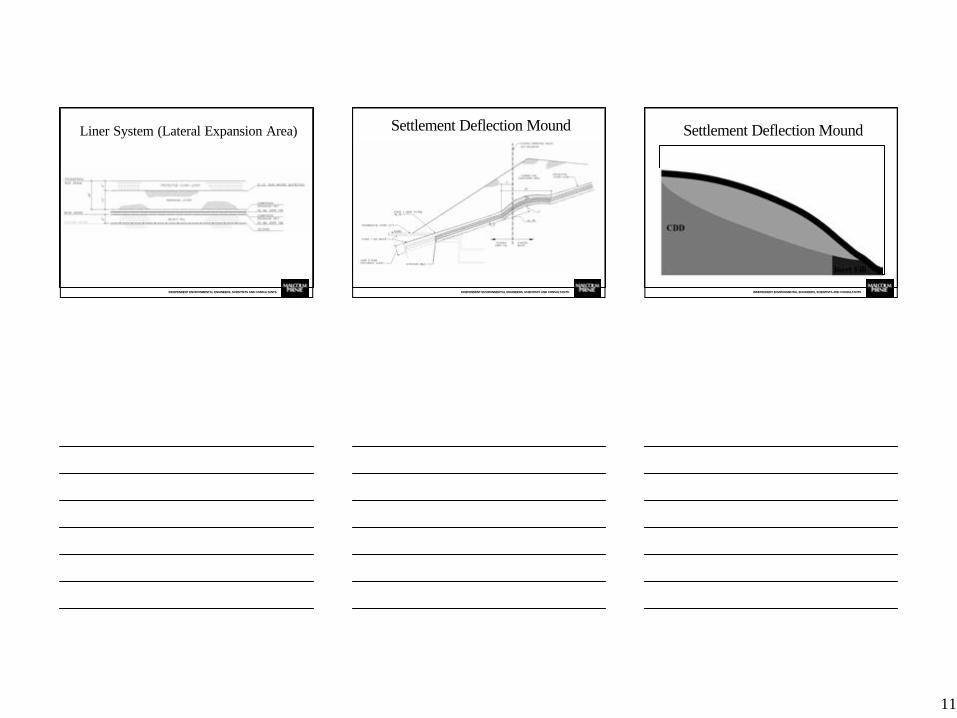
Liner System (Lateral Expansion Area)
INDEPENDENT ENVIRONMENTAL ENGINEERS, SCIENTISTS AND CONSULTANTS
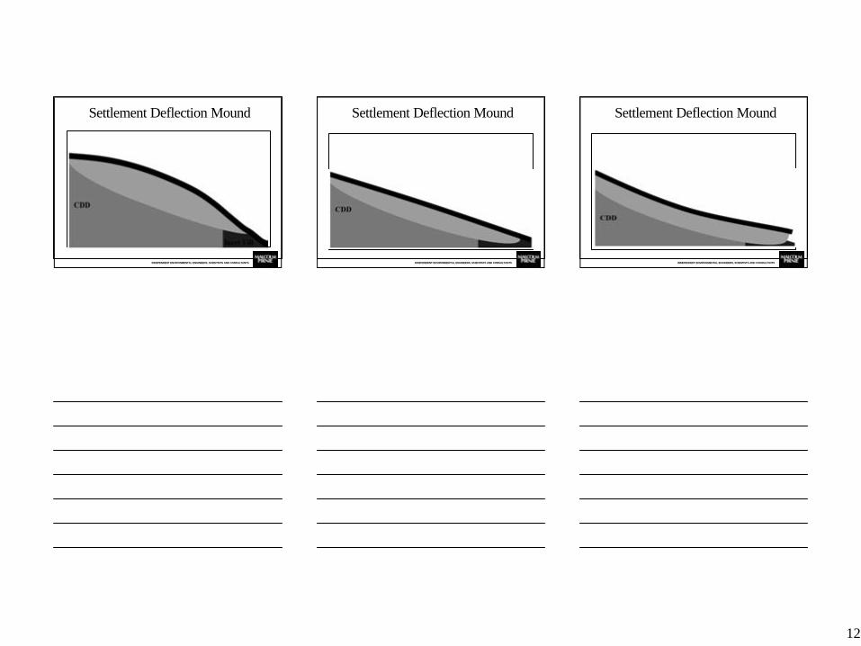
Settlement Deflection Mound
INDEPENDENT ENVIRONMENTAL ENGINEERS, SCIENTISTS AND CONSULTANTS
Settlement Deflection Mound
12
INDEPENDENT ENVIRONMENTAL ENGINEERS, SCIENTISTS AND CONSULTANTS
Settlement Deflection Mound
INDEPENDENT ENVIRONMENTAL ENGINEERS, SCIENTISTS AND CONSULTANTS
Settlement Deflection Mound
INDEPENDENT ENVIRONMENTAL ENGINEERS, SCIENTISTS AND CONSULTANTS
Settlement Deflection Mound
13
INDEPENDENT ENVIRONMENTAL ENGINEERS, SCIENTISTS AND CONSULTANTS
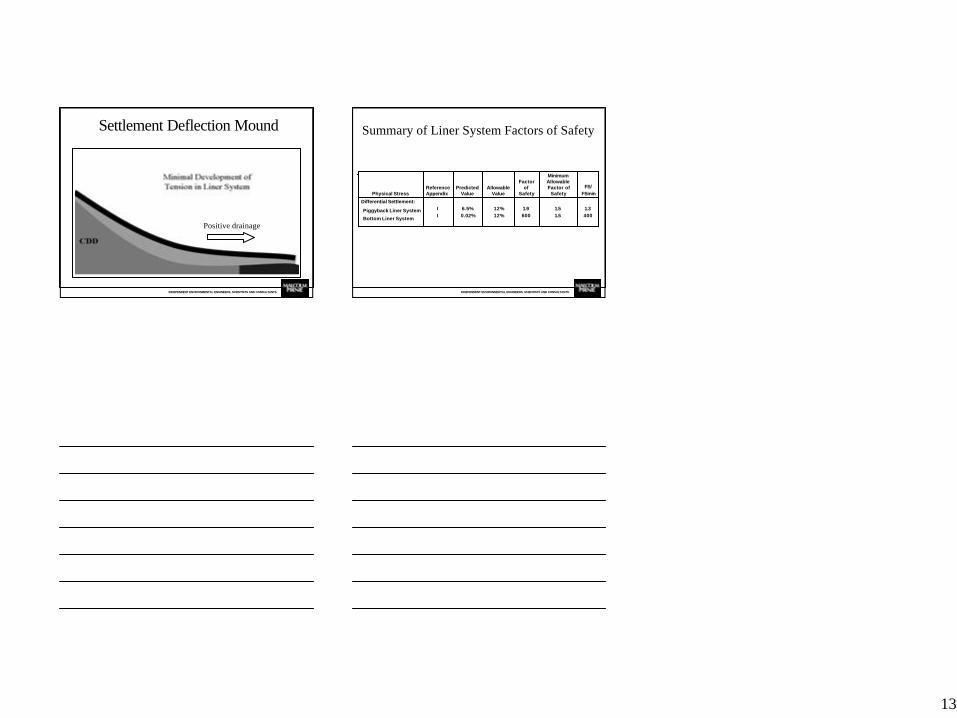
Settlement Deflection Mound
Positive drainage
INDEPENDENT ENVIRONMENTAL ENGINEERS, SCIENTISTS AND CONSULTANTS
Summary of Liner System Factors of Safety
1.3400
1.51.5
1.9600
12%12%
6.5%0.02%
II
Differential Settlement:
Piggyback Liner System
Bottom Liner System
FS/FSmin
Minimum Allowable Factor of
Safety
Factor of
SafetyAllowable
ValuePredicted
ValueReference AppendixPhysical Stress


