2005 Jeep Liberty Kj Owners Manual
424
TABLE OF CONTENTS SECTION PAGE 1 INTRODUCTION ............................................................. 3 2 THINGS TO KNOW BEFORE STARTING YOUR VEHICLE ............................. 11 3 UNDERSTANDING THE FEATURES OF YOUR VEHICLE .............................. 77 4 UNDERSTANDING YOUR INSTRUMENT PANEL ................................... 161 5 STARTING AND OPERATING ................................................. 217 6 WHAT TO DO IN EMERGENCIES .............................................. 291 7 MAINTAINING YOUR VEHICLE ............................................... 303 8 MAINTENANCE SCHEDULES .................................................. 359 9 IF YOU NEED CONSUMER ASSISTANCE ......................................... 389 10 INDEX .................................................................... 399 1 2 3 4 5 6 7 8 9 10
description
jeep manual
Transcript of 2005 Jeep Liberty Kj Owners Manual

TABLE OF CONTENTSSECTION PAGE
1 INTRODUCTION . . . . . . . . . . . . . . . . . . . . . . . . . . . . . . . . . . . . . . . . . . . . . . . . . . . . . . . . . . . . . 3
2 THINGS TO KNOW BEFORE STARTING YOUR VEHICLE . . . . . . . . . . . . . . . . . . . . . . . . . . . . . 11
3 UNDERSTANDING THE FEATURES OF YOUR VEHICLE . . . . . . . . . . . . . . . . . . . . . . . . . . . . . . 77
4 UNDERSTANDING YOUR INSTRUMENT PANEL . . . . . . . . . . . . . . . . . . . . . . . . . . . . . . . . . . . 161
5 STARTING AND OPERATING . . . . . . . . . . . . . . . . . . . . . . . . . . . . . . . . . . . . . . . . . . . . . . . . . 217
6 WHAT TO DO IN EMERGENCIES . . . . . . . . . . . . . . . . . . . . . . . . . . . . . . . . . . . . . . . . . . . . . . 291
7 MAINTAINING YOUR VEHICLE . . . . . . . . . . . . . . . . . . . . . . . . . . . . . . . . . . . . . . . . . . . . . . . 303
8 MAINTENANCE SCHEDULES . . . . . . . . . . . . . . . . . . . . . . . . . . . . . . . . . . . . . . . . . . . . . . . . . . 359
9 IF YOU NEED CONSUMER ASSISTANCE . . . . . . . . . . . . . . . . . . . . . . . . . . . . . . . . . . . . . . . . . 389
10 INDEX . . . . . . . . . . . . . . . . . . . . . . . . . . . . . . . . . . . . . . . . . . . . . . . . . . . . . . . . . . . . . . . . . . . . 399
1
2
3
4
5
6
7
8
9
10


INTRODUCTION
CONTENTS
� Introduction . . . . . . . . . . . . . . . . . . . . . . . . . . . 4
▫ Roll Over Warning . . . . . . . . . . . . . . . . . . . . . 5
� How To Use This Manual . . . . . . . . . . . . . . . . . . 7
� Warnings And Cautions . . . . . . . . . . . . . . . . . . . 7
� Vehicle Identification Number . . . . . . . . . . . . . . . 8
� Vehicle Modifications / Alterations . . . . . . . . . . . 9
1

INTRODUCTIONThank you for selecting a Jeep� Liberty and welcome toour worldwide family.
This is a specialized utility vehicle designed for bothon-road and off-road use. It can go places and performtasks for which conventional two-wheel drive vehicleswere not intended. However, on-road ride and handlingwill have a different feel from what drivers experiencewith other vehicles, so take time to become familiar withyour vehicle.
The two-wheel drive utility vehicle was designed foron-road use only. It is not intended for off-road drivingor use in other severe conditions suited to a four-wheeldrive vehicle.
Before you start to drive this vehicle, read this manual. Besure you are familiar with all vehicle controls, particu-larly those used for braking, steering and transmissionand transfer case shifting. Learn how your vehiclehandles on different road surfaces. Your driving skillswill improve with experience. When driving off-road orworking the vehicle, don’t overload it or expect it toovercome the laws of nature. Always observe federal,state, provincial, and local laws wherever you drive.
As with other vehicles of this type, failure to operate thisvehicle correctly may result in loss of control or anaccident. Be sure to read “On-Road/Off-Road DrivingTips” in Section 5 of this manual.
4 INTRODUCTION

Roll Over WarningUtility vehicles have a significantly higher roll over ratethan other types of vehicles. This vehicle has a higherground clearance, higher center of gravity, and narrowertrack than many passenger cars. It is capable of perform-ing better in a wide variety of off-road applications.Driven in an unsafe manner, all vehicles can be caused togo out of control. Because of the higher center of gravityand the narrower track, if this vehicle is out of control itmay roll over when some other vehicles may not.
Do not attempt sharp turns or abrupt maneuvers or otherunsafe driving actions that can cause loss of vehiclecontrol. Failure to operate this vehicle safely may resultin an accident, roll over of the vehicle, and severe or fatalinjury. Drive carefully.
Roll Over Warning Label
INTRODUCTION 5
1
Failure to use driver and passenger seat belts providedis a major cause of severe or fatal injury. In fact, the U.S.government notes that the universal use of existing seatbelts could cut the highway death toll by 10,000 or moreeach year, and could reduce disabling injuries by 2million annually. In a roll over crash an unbelted personis significantly more likely to die than a person wearinga seat belt. Always buckle up.
This manual has been prepared with the assistance ofservice and engineering specialists to acquaint you withthe operation and maintenance of your new vehicle. It issupplemented by a Warranty Information Booklet andvarious customer oriented documents. You are urged toread these publications carefully. Following the instruc-tions and recommendations in this manual will helpassure safe and enjoyable operation of your vehicle.
NOTE: After you read the manual, it should be storedin the vehicle for convenient reference and remain withthe vehicle when sold so that the new owner will beaware of all safety warnings.
When it comes to service, remember that the manufac-turer knows your vehicle best, has the factory-trainedtechnicians and genuine Mopar� parts, and is interestedin your satisfaction.
6 INTRODUCTION

WARNING!
Engine exhaust, some of its constituents, and certainvehicle components contain or emit chemicalsknown to the State of California to cause cancer andbirth defects or other reproductive harm. In addition,certain fluids contained in vehicles and certain prod-ucts of component wear contain or emit chemicalsknown to the State of California to cause cancer andbirth defects or other reproductive harm.
HOW TO USE THIS MANUALConsult the table of contents to determine which sectioncontains the information you desire.
The detailed index, at the rear of the manual, contains acomplete listing of all subjects.
WARNINGS AND CAUTIONSThis manual contains WARNINGS against operatingprocedures which could result in an accident or bodilyinjury. It also contains CAUTIONS against procedureswhich could result in damage to your vehicle. If you donot read this entire manual you may miss importantinformation. Observe all Warnings and Cautions.
INTRODUCTION 7
1

VEHICLE IDENTIFICATION NUMBERThe vehicle identification number (VIN) is located on astamped plate on the bottom of the left front A-Pillar,visible from outside of the vehicle through the wind-shield. This number also appears on the AutomobileInformation Disclosure Label affixed to a window onyour vehicle. Save this label for a convenient record ofyour vehicle identification number and optional equip-ment.
NOTE: It is illegal to remove the VIN plate.Vehicle Identification Number
8 INTRODUCTION

VEHICLE MODIFICATIONS / ALTERATIONS
WARNING!
Any modifications or alterations to this vehiclecould seriously affect its roadworthiness and safetyand may lead to an accident resulting in seriousinjury or death.
INTRODUCTION 9
1


THINGS TO KNOW BEFORE STARTING YOUR VEHICLE
CONTENTS
� A Word About Your Keys . . . . . . . . . . . . . . . . . .14
▫ Ignition Key . . . . . . . . . . . . . . . . . . . . . . . . . .14
▫ Key-In-Ignition Reminder . . . . . . . . . . . . . . . .16
� Sentry Key Immobilizer System . . . . . . . . . . . . . .16
▫ Important Note About Service . . . . . . . . . . . . .17
▫ Replacement Keys . . . . . . . . . . . . . . . . . . . . . .17
▫ Customer Key Programming . . . . . . . . . . . . . .18
▫ General Information . . . . . . . . . . . . . . . . . . . .18
� Steering Wheel Lock — If Equipped . . . . . . . . . .19
▫ To Manually Lock The Steering Wheel . . . . . . .19
▫ To Release The Steering Wheel Lock . . . . . . . . .19
� Illuminated Entry . . . . . . . . . . . . . . . . . . . . . . . .19
� Doors And Door Locks . . . . . . . . . . . . . . . . . . . .20
▫ Manual Door Locks . . . . . . . . . . . . . . . . . . . . .21
▫ Power Door Locks — If Equipped . . . . . . . . . .23
▫ Automatic Door Locks — If Equipped . . . . . . .23
▫ Child Protection Locks . . . . . . . . . . . . . . . . . .24
� Remote Keyless Entry . . . . . . . . . . . . . . . . . . . . .25
2

▫ To Unlock The Doors . . . . . . . . . . . . . . . . . . .25
▫ To Lock The Doors . . . . . . . . . . . . . . . . . . . . .26
▫ To Unlatch The Swing Gate Flip-Up Window . .26
▫ Panic Alarm . . . . . . . . . . . . . . . . . . . . . . . . . .27
▫ To Use The Panic Alarm . . . . . . . . . . . . . . . . .27
▫ To Program Additional Transmitters . . . . . . . . .28
▫ General Information . . . . . . . . . . . . . . . . . . . .28
▫ Transmitter Battery Service . . . . . . . . . . . . . . .29
� Security Alarm System — If Equipped . . . . . . . . .30
▫ To Set The Alarm . . . . . . . . . . . . . . . . . . . . . .30
▫ To Disarm The System . . . . . . . . . . . . . . . . . . .31
� Rear Swing Gate . . . . . . . . . . . . . . . . . . . . . . . .31
� Windows . . . . . . . . . . . . . . . . . . . . . . . . . . . . .35
▫ Power Windows — If Equipped . . . . . . . . . . . .35
▫ Wind Buffeting . . . . . . . . . . . . . . . . . . . . . . . .36
� Occupant Restraints . . . . . . . . . . . . . . . . . . . . . .37
▫ Lap/Shoulder Belts . . . . . . . . . . . . . . . . . . . . .38
▫ Lap/Shoulder Belt Operating Instructions . . . . .39
▫ Adjustable Upper Shoulder Belt Anchorage . . . .43
▫ Automatic Locking Mode — If Equipped . . . . .44
▫ Energy Management Feature . . . . . . . . . . . . . .45
▫ Seat Belt Pretensioners . . . . . . . . . . . . . . . . . . .46
▫ Enhanced Driver Seat Belt Use Reminder System(BeltAlert) . . . . . . . . . . . . . . . . . . . . . . . . . . .46
▫ Seat Belts And Pregnant Women . . . . . . . . . . . .47
▫ Seat Belt Extender . . . . . . . . . . . . . . . . . . . . . .48
12 THINGS TO KNOW BEFORE STARTING YOUR VEHICLE

▫ Driver And Front Passenger SupplementalRestraint Systems (SRS) — Airbags . . . . . . . . . .48
▫ Child Restraint . . . . . . . . . . . . . . . . . . . . . . . .63
� Engine Break-In Recommendations . . . . . . . . . . .73
� Safety Tips . . . . . . . . . . . . . . . . . . . . . . . . . . . .73
▫ Exhaust Gas . . . . . . . . . . . . . . . . . . . . . . . . . .73
▫ Safety Checks You Should Make InsideThe Vehicle . . . . . . . . . . . . . . . . . . . . . . . . . .74
▫ Safety Checks You Should Make Outside TheVehicle . . . . . . . . . . . . . . . . . . . . . . . . . . . . . .75
THINGS TO KNOW BEFORE STARTING YOUR VEHICLE 13
2
A WORD ABOUT YOUR KEYSThe keys for your new vehicle are enclosed in a plasticbag with the key code number on it. If you received yourkeys without the bag, ask your dealer to give you thenumber. The key code can also be obtained by the dealerfrom your vehicle invoice.
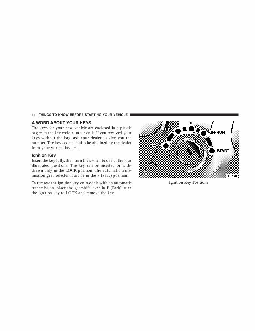
Ignition KeyInsert the key fully, then turn the switch to one of the fourillustrated positions. The key can be inserted or with-drawn only in the LOCK position. The automatic trans-mission gear selector must be in the P (Park) position.
To remove the ignition key on models with an automatictransmission, place the gearshift lever in P (Park), turnthe ignition key to LOCK and remove the key.
Ignition Key Positions
14 THINGS TO KNOW BEFORE STARTING YOUR VEHICLE

To remove the ignition key on models with a manualtransmission, depress and hold the key release button,turn the ignition key to LOCK and remove the key.
WARNING!
Leaving children in a vehicle unattended is danger-ous for a number of reasons. A child or others couldbe injured. Children should be warned not to touchthe parking brake, brake pedal, or the gear selectorlever. Do not leave the keys in the ignition. A childcould operate power windows, other controls, ormove the vehicle.
CAUTION!
An unlocked vehicle is an invitation to thieves.Always remove the key from the ignition, and lockall doors when leaving the vehicle unattended.Ignition Key Release Button
THINGS TO KNOW BEFORE STARTING YOUR VEHICLE 15
2

Key-In-Ignition ReminderIf you open the driver’s door and the key is fully insertedin the ignition switch, a chime will sound to remind youto remove the key.
SENTRY KEY IMMOBILIZER SYSTEMThe Sentry Key Immobilizer System (SKIS) preventsunauthorized operation of the vehicle by disabling theengine. The system will shut the engine down after 2seconds of running if an invalid key is used to start thevehicle. This system utilizes ignition keys which have anelectronic chip (transponder) embedded into them. Onlykeys that have been programmed to the vehicle can beused to start and operate the vehicle for longer than the2 second validation time period.
The Sentry Key Immobilizer System does not need to bearmed or activated. Operation of the system is automaticregardless of whether or not the vehicle is locked orunlocked. During normal operation, the “Sentry Key/
Security Alarm Indicator Light” (located in the instru-ment cluster) will come on for 3 seconds immediatelyafter the ignition switch is turned on for a bulb check.Afterwards, if the bulb remains on, this indicates amalfunction in the electronics. If the bulb begins to flashimmediately after the ignition switch is turned on, thisindicates that an invalid key is being used to start thevehicle. Both of these conditions will result in the enginebeing shut down after 2 seconds of running. Keep inmind that a key which has not been programmed is alsoconsidered an invalid key even if it is cut to fit theignition for that vehicle.
If the “Sentry Key/Security Alarm Indicator Light”comes on during normal vehicle operation (it has beenrunning for longer than 10 seconds) a fault has beendetected in the electronics and the vehicle should beserviced as soon as possible.
16 THINGS TO KNOW BEFORE STARTING YOUR VEHICLE
NOTE:• The Sentry Key Immobilizer System is not compatible
with remote starting systems. Use of these systemsmay result in vehicle starting problems and loss ofsecurity protection.
• Mobil Speedpass™, additional Sentry Keys, or anyother transponder equipped components on the samekeychain will not cause a key-related (Transponder)fault unless the additional part is physically heldagainst the ignition key being used when starting thevehicle. Also, cell phones, pagers, or other RF electron-ics will not cause interference with this system.
All of the keys provided with your new vehicle havebeen programmed to the vehicle electronics.
Important Note About ServiceA four digit PIN number is needed to service the SentryKey Immobilizer System. This number can be obtainedfrom your authorized dealer. However, this number canalso be found on your customer invoice that you weregiven upon receipt of your vehicle.
Replacement Keys
NOTE: Only keys that have been programmed to thevehicle electronics can be used to start the vehicle. Oncea Sentry Key has been programmed to a vehicle, it cannotbe programmed to any other vehicle.
At the time of purchase, the original owner is providedwith a four digit PIN number. This number is requiredfor dealer replacement of keys. Duplication of keys maybe performed at an authorized dealer or by using theCustomer Key Programming procedure. This procedure
THINGS TO KNOW BEFORE STARTING YOUR VEHICLE 17
2

consists of programming a blank key to the vehicleelectronics. A blank key is one which has never beenprogrammed.
NOTE: When having the Sentry Key System serviced,bring all vehicle keys to the dealer.
Customer Key Programming
You can program new keys to the system if you have twovalid keys by doing the following:
1. Cut the additional Sentry Key Transponder blank(s) tomatch the ignition switch lock cylinder key code.
2. Insert the first valid key into the ignition switch andturn the ignition switch ON for at least 3 seconds but nolonger than 15 seconds. Turn the ignition switch OFF andremove the first key.
3. Insert the second valid key and turn the ignitionswitch ON within 15 seconds. After ten seconds, a chime
will sound and the “Sentry Key/Security Alarm Indica-tor Light” will begin to flash. Turn the ignition switchOFF and remove the second key.
4. Insert a blank Sentry Key into the ignition switch andturn the ignition switch ON within 60 seconds. After 10seconds, a single chime will sound. The “Sentry Key/Security Alarm Indicator Light” will stop flashing, turnon for 3 seconds; then turn off.
The new Sentry Key has been programmed. Repeat thisprocess to program up to a total of 8 keys.
General InformationThe Sentry Key Immobilizer System complies with FCCrules part 15 and with RSS-210 of Industry Canada.Operation is subject to the following two conditions:
1. This device may not cause harmful interference.
18 THINGS TO KNOW BEFORE STARTING YOUR VEHICLE

2. This device must accept any interference that may bereceived, including interference that may cause undes-ired operation.
STEERING WHEEL LOCK — IF EQUIPPEDYour vehicle may be equipped with a passive steeringwheel lock (manual transmission only). This lock pre-vents steering the vehicle without the ignition key. If thesteering wheel is moved a half turn in either directionand the key is not in the ignition, the steering wheel willlock.
To Manually Lock the Steering WheelWith the engine running, rotate the steering wheel 1/2revolution from straight ahead position, turn off theengine and remove the key. Rotate the steering wheelslightly in both directions until the lock engages.
To Release the Steering Wheel LockInsert the key in the ignition and turn the wheel slightlyto the right or left to disengage the lock.
NOTE: If you turned the wheel to the right to engagethe lock, you must turn the wheel slightly to the right todisengage it. If you turned the wheel to the left to engagethe lock, turn the wheel slightly to the left to disengage it.
ILLUMINATED ENTRYThe interior lights come on when you open any door.They will remain on for about 30 seconds after all doorsare closed then fade to off, unless, the dome inhibitfeature was selected on the multi-function control lever.Refer to LIGHTS in Section 3 of this manual.
The lights also will fade to off if you turn on the ignitionafter you close all the doors.
THINGS TO KNOW BEFORE STARTING YOUR VEHICLE 19
2

DOORS AND DOOR LOCKSThe vacuum fluorescent (VF) display located in theodometer area displays the word “door” as an indicationof a door ajar or door not completely closed. When thevehicle is not moving and the door is ajar or notcompletely closed, the VF display will show the word“door” and then show the odometer/trip odometermileage (each for 2 seconds). The display will continue tocycle.
NOTE: If vehicle is equipped with the optional Elec-tronic Vehicle Information Center (EVIC) in the overheadconsole, all warnings including “door”, “GATE”,“GLASS”, and “LOWASH” will only be displayed in theEVIC display (not in the instrument cluster). For addi-tional information, refer to “Overhead Console — IfEquipped” in Section 3.
If any other active warnings including “GATE”,“GLASS”, or “LOWASH” are present, they will be shownin the VF display and will also continue to cycle. If thevehicle is moving, three single chimes will occur (One
Door Open Display
20 THINGS TO KNOW BEFORE STARTING YOUR VEHICLE

chime for each complete display cycle (three cycles total).After this, the display will continue to cycle only (nochimes).
If the trip/reset button is pressed while the VF warningsare being displayed, the VF display will revert back toonly displaying the odometer/trip odometer mileage.
Manual Door LocksUse the manual door lock plunger to lock the doors frominside the vehicle. If the plunger is down when the dooris closed, the door will lock. Therefore, make sure thekeys are not inside the vehicle before closing the door.
Door Lock Plunger
THINGS TO KNOW BEFORE STARTING YOUR VEHICLE 21
2

WARNING!
• For personal security, and safety in the event of anaccident, lock the vehicle doors as you drive aswell as when you park and leave the vehicle.
• When leaving the vehicle always remove the keyfrom the ignition lock, and lock your vehicle. Donot leave children unattended in the vehicle, orwith access to an unlocked vehicle. Unsuperviseduse of vehicle equipment may cause severe per-sonal injuries and death.
CAUTION!
An unlocked vehicle is an invitation to thieves.Always remove the key from the ignition and lockall of the doors when leaving the vehicle unattended.
22 THINGS TO KNOW BEFORE STARTING YOUR VEHICLE

Power Door Locks — If EquippedA door lock switch is on each front door panel. Press thisswitch to lock or unlock the doors.
If the plunger is down when the door is closed, the doorwill lock. Therefore, make sure the keys are not inside thevehicle before closing the door.
If you press the door lock switch while the keys are in theignition switch, and the driver’s door is open, the doorswill not lock.
The rear doors cannot be opened from inside the vehicleuntil you pull up the lock plungers.
Automatic Door Locks — If Equipped
The doors will lock automatically if:
1. all doors are closed,
2. vehicle speed is above 15 mph (24 km/h),
3. and the accelerator pedal is depressed.
This will occur only once, will not reoccur until a door isopened.
Power Door Lock Switch
THINGS TO KNOW BEFORE STARTING YOUR VEHICLE 23
2

Child Protection LocksThe rear doors of your vehicle are equipped with childprotection locks. If you push up on the lever on the openedge of the door it cannot be opened from the inside ofthe vehicle. Push the lever down to disengage the childprotection locks.
WARNING!
Avoid trapping anyone in the vehicle in a collision.Remember that the rear doors can only be openedfrom the outside when the child protection locks areengaged. Child Lock Control
24 THINGS TO KNOW BEFORE STARTING YOUR VEHICLE

REMOTE KEYLESS ENTRYThis system allows you to lock or unlock the doors oropen the swing gate flip-up window from distances of23–50 feet (7–15 meters) using a transmitter. You don’thave to point the transmitter at the vehicle to activate thesystem. Each vehicle comes with two transmitters.
To Unlock the DoorsPress and release the “Unlock” button once to unlock thedriver’s door. Press the button again within 5 seconds tounlock all the doors. If your vehicle is equipped withIlluminated Entry, the interior lights also come on andremain on for about 30 seconds, when you unlock thedoors. The park lights will flash twice to acknowledgethe unlock signal.
NOTE: The transmitter can be programmed to unlockall the doors upon the first press of the �Unlock� button(within 23–50 feet (7–15 meters) of the vehicle) by per-forming the following procedure:
1. Press and hold the �Unlock� button on the transmitter.
2. Continue to hold the �Unlock� button, wait at least 4but no longer than 10 seconds, then press the “Lock”button.
3. Release both buttons.Four Button Transmitter
THINGS TO KNOW BEFORE STARTING YOUR VEHICLE 25
2

4. Repeating steps 1–3 will restore original operation.
NOTE: The Light Flash can be enabled or disabled(within 23–50 feet (7–15 meters) of the vehicle) by per-forming the following procedure:
1. Press and hold the �Lock� button on the transmitter.
2. Continue to hold the �Lock� button, wait at least 4 butno longer than 10 seconds, then press the “Rear Release”button.
3. Release both buttons.
4. Repeating steps 1–3 will restore original transmitteroperation.
To Lock the DoorsPress and release the “Lock” button once to lock thedoors, swing gate flip-up window, and swing gate.
The horn will chirp and the park lights will flash once toacknowledge the lock signal.
NOTE: The horn chirp can be enabled or disabled(within 23–50 feet (7–15 meters) of the vehicle) by thefollowing procedure:
1. Press and hold the �Lock� button on the transmitter.
2. Continue to hold the �Lock� button, wait at least 4 butno longer than 10 seconds, then press the �Unlock�button.
3. Release both buttons.
4. Repeating steps 1–3 will restore original transmitteroperation.
To Unlatch the Swing Gate Flip-Up WindowPress the “Rear Release” button twice to unlatch theswing gate flip-up window.
26 THINGS TO KNOW BEFORE STARTING YOUR VEHICLE

WARNING!
To avoid injury stand back when opening. Glass willautomatically rise.
NOTE: The transmitter can be programmed to unlatchthe flip-up window immediately upon activation of the“Rear Release” button (without pressing and holding)(within 23–50 feet (7–15 meters) of the vehicle) by per-forming the following procedure:
1. Press and hold the “Unlock” button on the transmitter.
2. Continue to hold the “Unlock” button, wait at least 4but no longer than 10 seconds, then press the “RearRelease” button.
3. Release both buttons.
4. Repeating steps 1–3 will restore original transmitteroperation.
NOTE: Unlatching the flip-up window will unlock theswing gate. After closing the flip-up window, press the“Lock” button on the transmitter to lock the swing gate.
Panic AlarmThe panic mode flashes the park lights, and sounds thehorn for about 3 minutes or until the alarm is turned off.
To Use the Panic AlarmPress and hold the PANIC button for at least 1 second toactivate the panic alarm. Press and hold the PANICbutton a second time to deactivate the alarm. The alarmwill also shut itself off after starting the vehicle andaccelerating to 15 mph (24 km/h).
NOTE: The “Panic” and “Security” alarms are quitedifferent. Please take a moment to activate the “Panic”and the “Security” modes to hear the differences in thehorn. In case one should go off in the future, you willneed to know which mode has been activated in order todeactivate it.
THINGS TO KNOW BEFORE STARTING YOUR VEHICLE 27
2

To Program Additional Transmitters
NOTE: If vehicle is equipped with the optional Elec-tronic Vehicle Information Center (EVIC) in the overheadconsole, the transmitters may also be programmedthrough the EVIC display. For additional information,refer to “Overhead Console — If Equipped” in Section 3.
Up to 4 transmitters can be programmed to your vehicle.To obtain additional transmitters, contact your autho-rized dealer. To program a transmitter (within 23–50 feet(7–15 meters) of the vehicle), perform the followingprocedure:
1. Gather every transmitter that is to be used with thevehicle including any transmitters that are currentlyprogrammed.
2. Enter Program Mode: Turn the ignition to the ONposition, and using a currently programmed transmitter;press and hold the �Unlock� button on the transmitter.
Continue to hold the “Unlock” button, wait at least 4 butno longer than 10 seconds, then press and hold thePANIC button for at least 1 second. Release both buttonssimultaneously.
3. Program Each Transmitter: All transmitters to be usedwith your vehicle must be programmed as follows:
Press and release the �Lock� and �Unlock� buttons simul-taneously, followed by a press and release of ANY buttonon each transmitter to be programmed. You will hear achime when a transmitter has been successfully pro-grammed.
General InformationThis transmitter complies with FCC rules part 15 andwith RSS-210 of Industry Canada. Operation is subject tothe following two conditions:
1. This device may not cause harmful interference.
28 THINGS TO KNOW BEFORE STARTING YOUR VEHICLE

2. This device must accept any interference that may bereceived, including interference that may cause undes-ired operation.
If your Remote Keyless Entry fails to operate from anormal distance, check for these two conditions:
1. Weak batteries in transmitter. The expected life ofbatteries is from one to two years
2. Closeness to a radio transmitter such as a radio stationtower, airport transmitter, and some mobile or CB radios.
Transmitter Battery ServiceThe recommended replacement battery is the PanasonicCR2032 or equivalent.
1. Pry the transmitter halves apart with a dime or similarobject. Make sure not to damage the rubber gasketmaterial during removal.
2. Remove and replace the batteries. Avoid touching thenew batteries with your fingers. Skin oils may causebattery deterioration. If you touch the battery, clean itwith rubbing alcohol.
3. Reassemble the transmitter case. Snap the halvestogether and test transmitter operation.
Separating Transmitter Halves
THINGS TO KNOW BEFORE STARTING YOUR VEHICLE 29
2

SECURITY ALARM SYSTEM — IF EQUIPPEDThis system monitors the vehicle doors, swing gate,swing gate flip-up window, and ignition for unautho-rized operation. When the alarm is activated, the systemprovides both audible and visual signals. The horn,headlights, and tail lights will sound/flash repeatedly forthree minutes. If disturbance is still present (driver’sdoor, passenger door, other doors, ignition) after threeminutes, the headlights and tail lights will flash for anadditional 15 minutes.
NOTE: The “Panic” and “Security” alarms are quitedifferent. Please take a moment to activate the “Panic”and the “Security” modes to hear the differences in thehorn. In case one should go off in the future, you willneed to know which mode has been activated in order todeactivate it.
To Set the AlarmThe alarm will set when you use the remote keyless entrytransmitter to lock the doors and swing gate or when youuse the power door lock switch while the door is open.After all the doors are locked and closed, the “SentryKey/Security Alarm Indicator Light” (located in theinstrument cluster) will flash rapidly for about 16 sec-onds to signal that the system is arming. During this 16second arming period, opening any door or the swinggate will cancel the arming. If the system successfullyarms, the “Sentry Key/Security Alarm Indicator Light”will flash at a slower rate to indicate the alarm is set.
30 THINGS TO KNOW BEFORE STARTING YOUR VEHICLE

To Disarm the SystemTo disarm the system, you will need to press the “Un-lock” button on the remote keyless entry transmitter orturn the ignition key to the RUN position. If somethinghas triggered the system in your absence, the horn willsound three times when you unlock the doors. Check thevehicle for tampering.
NOTE: On vehicles equipped with Remote KeylessEntry (RKE), there will not be a door lock cylinder on thefront passenger door, rear doors, or rear swing gate.Therefore, you will be unable to disarm the system witha manual unlock of the passenger or rear doors.
The Security Alarm System is designed to protect yourvehicle; however, you can create conditions where thesystem will arm unexpectedly. If you remain in thevehicle and lock the doors with the transmitter, once thesystem is armed (after 16 seconds), when you pull thedoor handle to exit the alarm will sound. If this occurs,
press the “Unlock” button on the remote keyless entrytransmitter to disarm the system. You may also acciden-tally disarm the system by unlocking the driver’s doorwith the key and then locking it. The door will be lockedbut the Security Alarm will not arm.
REAR SWING GATEThe swing gate can be unlocked using the remote keylessentry, or by activating the power door lock switcheslocated on the front doors.
WARNING!
To avoid injury stand back when opening. Glass willautomatically rise.
THINGS TO KNOW BEFORE STARTING YOUR VEHICLE 31
2

To open the swing gate, pull the gate handle to its firstdetent to open just the flip-up window. Pull the handle toits second detent (all the way) to open both the flip-upwindow and swing gate.
WARNING!
To avoid injury stand back when opening. Glass willautomatically rise.
The vacuum fluorescent (VF) display located in theodometer area displays the words “GATE” and/or“GLASS” as an indication of when the swing gate and/orflip-up window, is not completely closed. When thevehicle is not moving and the swing gate and/or flip-upwindow is not completely closed, the VF display willshow the word “GATE” and/or “GLASS” and then showthe odometer/trip odometer mileage (each for 2 sec-onds). The display will continue to cycle.
NOTE: If vehicle is equipped with the optional Elec-tronic Vehicle Information Center (EVIC) in the overheadconsole, all warnings including “door”, “GATE”,“GLASS”, and “LOWASH” will only be displayed in the
Swing Gate Release
32 THINGS TO KNOW BEFORE STARTING YOUR VEHICLE

EVIC display (not in the instrument cluster). For addi-tional information, refer to “Overhead Console — IfEquipped” in Section 3.
If any other active warnings including “door” or “LO-WASH” are present, they will be shown in the VF displayand will also continue to cycle. If the vehicle is moving,two single chimes will occur if the rear glass is open orthree single chimes will occur if the rear swing gate is
Gate Open Display
Glass Open Display
THINGS TO KNOW BEFORE STARTING YOUR VEHICLE 33
2

open (one chime for each complete display cycle). Afterthis, the VF display will continue to sequence only (nochimes).
If the trip/reset button is pressed while the VF warningsare being displayed, the VF display will revert back toonly displaying the odometer/trip odometer mileage.
NOTE: Close swing gate before flip-up window.
CAUTION!
Do not press on rear wiper blade when closingswing gate, as damage to the blade will result.
WARNING!
Driving with the flip-up window open can allowpoisonous exhaust gases into your vehicle. You andyour passengers could be injured by these fumes.Keep the flip-up window closed when you areoperating the vehicle.
NOTE: The rear swing gate will lock while the rearwiper is operating. The gate will stay locked until thewiper is turned off and the gate is unlocked (by key,lock switch, or key fob).
NOTE: The swing gate will lock automatically when thevehicle begins moving.
34 THINGS TO KNOW BEFORE STARTING YOUR VEHICLE

WINDOWS
Power Windows — If EquippedThe power window switches are located on the centerfloor console. The top left switch controls the left frontwindow and the top right switch controls the right frontwindow. The lower left switch controls the left rearpassenger window, and the lower right switch controlsthe right rear passenger window. The switches willcontinue to function for up to 10 minutes after theignition key has been removed, or until a door is opened.
The window lock switch located next to the windowswitches allows you to disable the rear passenger win-dow switches that are located on the back of the centerfloor console.
Power Window Switches
THINGS TO KNOW BEFORE STARTING YOUR VEHICLE 35
2

Auto Down Feature — If EquippedThe driver’s and passenger’s front window switcheshave an auto down feature. Press the window switch pastthe detent, release, and the window will go down auto-matically.
To open the window part way, press the window switchpart way and release it when you want the window tostop.
Rear Passenger Window SwitchesThe rear passenger window switches are located on theback of the center floor console.
Wind Buffeting
Wind buffeting can be described as the perception ofpressure on the ears or a helicopter type sound in theears. Your vehicle may exhibit wind buffeting with the
Rear Power Window Switches
36 THINGS TO KNOW BEFORE STARTING YOUR VEHICLE

windows down, or the sunroof (if equipped) in certainopen or partially open positions. This is a normal occur-rence and can be minimized. If the buffeting occurs withthe sunroof open, adjust the sunroof opening to minimizethe buffeting.
OCCUPANT RESTRAINTSSome of the most important safety features in yourvehicle are the restraint systems. These include the frontand rear seat belts for the driver and all passengers, frontairbags for both the driver and front passenger and, ifequipped, window bags for the driver and passengersseated next to a window. If you will be carrying childrentoo small for adult-size belts, your seat belts also can beused to hold infant and child restraint systems.
NOTE: The front airbags have a multi stage inflatordesign. This allows the airbag to have different rates ofinflation that are based on collision severity.
Please pay close attention to the information in thissection. It tells you how to use your restraint systemproperly to keep you and your passengers as safe aspossible.
WARNING!
In a collision, you and your passengers can suffermuch greater injuries if you are not properly buck-led up. You can strike the interior of your vehicle orother passengers, or you can be thrown out of thevehicle. Always be sure you and others in yourvehicle are buckled up properly.
Buckle up even though you are an excellent driver, evenon short trips. Someone on the road may be a poor driverand cause a collision which includes you. This canhappen far away from home or on your own street.
THINGS TO KNOW BEFORE STARTING YOUR VEHICLE 37
2

Research has shown that seat belts save lives, and theycan reduce the seriousness of injuries in a collision. Someof the worst injuries happen when people are thrownfrom the vehicle. Seat belts reduce the possibility ofejection and the risk of injury caused by striking theinside of the vehicle. Everyone in a motor vehicle shouldbe belted at all times.
Lap/Shoulder BeltsAll the seats in your vehicle are equipped with lap/shoulder belts.
The belt webbing retractor is designed to lock duringvery sudden stops or collisions. This feature allows theshoulder part of the belt to move freely with you undernormal conditions. But in a collision, the belt will lockand reduce the risk of you striking the inside of thevehicle or being thrown out.
WARNING!
• Wearing a seat belt incorrectly is dangerous. Seatbelts are designed to go around the large bones ofyour body. These are the strongest parts of yourbody and can take the forces of a collision thebest. Wearing your belt in the wrong place couldmake your injuries in a collision much worse. Youmight suffer internal injuries, or you could evenslide out of part of the belt. Follow these instruc-tions to wear your seat belt safely and to keepyour passengers safe, too.
• Two people should never be belted into a singleseat belt. People belted together can crash into oneanother in an accident, hurting one another badly.Never use a lap/shoulder belt or a lap belt formore than one person, no matter what their size.
38 THINGS TO KNOW BEFORE STARTING YOUR VEHICLE

Lap/Shoulder Belt Operating Instructions
1. Enter the vehicle and close the door. Sit back andadjust the seat.
2. The seat belt latch plate is above the back of your seat.Grasp the latch plate and pull out the belt. Slide the latchplate up the webbing as far as necessary to make the beltgo around your lap.
Latch Plate
THINGS TO KNOW BEFORE STARTING YOUR VEHICLE 39
2

3. When the belt is long enough to fit, insert the latchplate into the buckle until you hear a “click.”
WARNING!
A belt that is buckled into the wrong buckle will notprotect you properly. The lap portion could ride toohigh on your body, possibly causing internal injuries.Always buckle your belt into the buckle nearest you.A belt that is too loose will not protect you as well. In asudden stop you could move too far forward, increasingthe possibility of injury. Wear your seat belt snugly.A belt that is worn under your arm is very dangerous.Your body could strike the inside surfaces of the vehiclein a collision, increasing head and neck injury. A beltworn under the arm can cause internal injuries. Ribsaren’t as strong as shoulder bones. Wear the belt overyour shoulder so that your strongest bones will take theforce in a collision.A shoulder belt placed behind will not protect you frominjury during a collision. You are more likely to hit yourhead in a collision if you do not wear your shoulder belt.The lap and shoulder belt are meant to be used together.
Latch Plate To Buckle
40 THINGS TO KNOW BEFORE STARTING YOUR VEHICLE

4. Position the lap belt across your thighs, below yourabdomen. To remove slack in the lap portion, pull up abit on the shoulder belt. To loosen the lap belt if it is tootight, tilt the latch plate and pull on the lap belt. A snugbelt reduces the risk of sliding under the belt in acollision.
NOTE: The “Seat Belt Indicator Light” will remain onuntil the driver’s seat belt is buckled.
Removing Slack From Belt
THINGS TO KNOW BEFORE STARTING YOUR VEHICLE 41
2

WARNING!
A lap belt worn too high can increase the risk ofinjury in a collision. The belt forces won’t be at thestrong hip and pelvic bones, but across your abdo-men. Always wear the lap part of your seat belt aslow as possible and keep it snug.
A twisted belt cannot do its job as well. In a collisionit could even cut into you. Be sure the belt is straight.If you cannot straighten a belt in your vehicle, take itto your authorized dealer and have it fixed.
5. Position the shoulder belt on your chest so that it iscomfortable and not resting on your neck. The retractorwill withdraw any slack in the belt.
6. To release the belt, push the red button marked PRESSon the buckle. The belt will automatically retract to itsstowed position. If necessary, slide the latch plate downthe webbing to allow it to retract fully.
WARNING!
A frayed or torn belt could rip apart in a collisionand leave you with no protection. Inspect the beltsystem periodically, checking for cuts, frays, or looseparts. Damaged parts must be replaced immediately.Do not disassemble or modify the system. Seat beltassemblies must be replaced after an accident if theyhave been damaged (bent retractor, torn webbing,pretensioner, etc.).
42 THINGS TO KNOW BEFORE STARTING YOUR VEHICLE

Adjustable Upper Shoulder Belt AnchorageIn the front seat positions, the shoulder belt can beadjusted upward or downward to position the belt awayfrom your neck. To lower the shoulder belt height, pushthe button and slide the height adjuster down. To raisethe height of the shoulder belt, slide the height adjusterup. Pull down on the height adjuster to make sure it islocked in place.
Adjusting Upper Shoulder Belt
THINGS TO KNOW BEFORE STARTING YOUR VEHICLE 43
2

WARNING!
Position the shoulder belt height adjusters so thatthe belt rests across the middle of your shoulder.Failure to adjust the safety belt properly couldreduce the effectiveness of the seat belt and increasethe risk of injury in a collision.
As a guide, if you are shorter than average, you willprefer a lower position, and if you are taller than average,you’ll prefer a higher position. When you release theanchorage, try to move it up or down to make sure thatit is locked in position.
Automatic Locking Mode — If EquippedIn this mode, the shoulder belt is automatically pre-locked. The belt will still retract to remove any slack inthe shoulder belt.
When To Use The Automatic Locking ModeAnytime a child safety seat is installed in a passengerfront or outboard rear seating position (if equipped).Children 12 years old and under should be properlyrestrained in the rear seat whenever possible.
How To Use The Automatic Locking Mode
1. Buckle the combination lap and shoulder belt.
2. Grasp the shoulder portion and pull downward untilthe entire belt is extracted.
3. Allow the belt to retract. As the belt retracts, you willhear a clicking sound. This indicates the safety belt isnow in the automatic locking mode.
How to Disengage The Automatic Locking ModeDisconnect the combination lap/shoulder belt and allowit to retract completely to disengage the automatic lock-ing mode and activate the vehicle sensitive (emergency)locking mode.
44 THINGS TO KNOW BEFORE STARTING YOUR VEHICLE

Energy Management FeatureThis vehicle has a safety belt system with an energymanagement feature at the driver and front passengerseating positions to help further reduce the risk of injuryin the event of a head-on collision.
This safety belt system has a retractor assembly that isdesigned to pay out webbing in a controlled manner. Thisfeature is designed to help reduce the belt force acting onthe occupant’s chest.
WARNING!
• After a vehicle collision, the driver and frontpassenger outboard seat belt system must bechecked by a qualified technician to verify thatthe “automatic locking retractor” feature for childseats is still functioning properly. In addition, allseat belts should be checked for proper function.
• The belt and retractor assembly must be replacedif the seat belt assembly “automatic locking re-tractor” feature or any other seat belt function isnot working properly when checked according tothe procedures in the Service Manual.
• Failure to replace the belt and retractor assemblycould increase the risk of injury in collisions.
THINGS TO KNOW BEFORE STARTING YOUR VEHICLE 45
2
Seat Belt PretensionersThe driver and front passenger seat belts are equippedwith a pretensioning device that is designed to removeany slack from the seat belt systems in the event of acollision. This device improves the performance of theseat belt by assuring that the belt is tight around theoccupant early in a collision. Pretensioners work for allsize occupants, including those in child restraints.
NOTE: These devices are not a substitute for proper seatbelt placement by the occupant. The seat belt must still beworn snugly and positioned properly.
The pretensioners are triggered by the front AirbagControl Module. Like the front airbags, the pretensionersare a single use item. After a collision that is severeenough to deploy the airbags and pretensioners, theymust be replaced.
Enhanced Driver Seat Belt Use Reminder System(BeltAlert)If the driver’s seat belt has not been buckled within 60seconds of starting the vehicle and if the vehicle speed isgreater than 5 mph (8 km/h), the Enhanced WarningSystem (BeltAlert) will alert the driver to buckle their seatbelt. The driver should also instruct all other occupants tobuckle their seat belts. Once the warning is triggered, theEnhanced Warning System (BeltAlert) will continue tochime and flash the Seat Belt Warning Light for 96seconds or until the driver’s seat belt is buckled.
The Enhanced Warning System (BeltAlert) will be reacti-vated if the driver’s seat belt is unbuckled for more than10 seconds and the vehicle speed is greater than 5 mph (8km/h).
46 THINGS TO KNOW BEFORE STARTING YOUR VEHICLE

The Enhanced Warning System (BeltAlert) can be en-abled or disabled by your authorized dealer or byfollowing these steps:
NOTE: The following steps must occur within the first60 seconds of the ignition switch being turned to the ONor START position. The manufacturer does not recom-mend deactivating the Enhanced Warning System(BeltAlert).
1. Turn the ignition switch to the OFF position, andbuckle the driver’s seat belt.
2. Turn the ignition key to the ACCESSORY/RUN posi-tion (engine does not need to be running), and wait forthe Seat Belt Warning Light to turn off.
3. Within 60 seconds of starting the vehicle, unbuckleand then re-buckle the driver’s seat belt at least threetimes within 10 seconds, ending with the seat beltbuckled.
4. Turn the ignition key to the OFF position. A singlechime will sound to signify that you have successfullycompleted the programming.
The Enhanced Warning System (BeltAlert) can be reacti-vated by repeating this procedure.
NOTE: Although the Enhanced Warning System(BeltAlert) has been deactivated, the Seat Belt WarningLight will continue to illuminate while the driver’s seatbelt remains unfastened.
Seat Belts and Pregnant WomenWe recommend that pregnant women use the seat beltsthroughout their pregnancy. Keeping the mother safe isthe best way to keep the baby safe.
Pregnant women should wear the lap part of the beltacross the thighs and as snug across the hips as possible.Keep the belt low so that it does not come across theabdomen. That way the strong bones of the hips will takethe force if there is a collision.
THINGS TO KNOW BEFORE STARTING YOUR VEHICLE 47
2

Seat Belt ExtenderIf a seat belt is too short, even when fully extended andwhen the adjustable upper shoulder belt anchorage (ifequipped) is in its lowest position, your authorizeddealer can provide you with a seat belt extender. Thisextender should be used only if the existing belt is notlong enough. When it is not required, remove the ex-tender and store it.
WARNING!
Using a seat belt extender when not needed canincrease the risk of injury in a collision. Only usewhen the lap belt is not long enough when it is wornlow and snug, and in the recommended seatingpositions. Remove and store the extender when notneeded.
Driver And Front Passenger SupplementalRestraint Systems (SRS) — Airbags
This vehicle has airbags for both the driver and rightfront passenger as a supplement to the seat belt restraintsystems. The driver’s front airbag is mounted in thesteering wheel. The passenger side airbag is mounted in
Front Airbag Components
48 THINGS TO KNOW BEFORE STARTING YOUR VEHICLE

the instrument panel, above the glove compartment. Thewords SRS/AIRBAG are embossed on the airbag covers.
NOTE: The front airbags are certified to the Federalregulations that allow less forceful deployment.
The front airbags have a multi stage inflator design. Thismay allow the airbag to have different rates of inflationthat are based on collision severity and occupant size.Also, the front passenger airbag is certified to the Federalregulations that define Occupant Classification (Refer to“Occupant Classification System” in this section).
This vehicle may also be equipped with window bags toprotect the driver, front, and rear passengers sitting nextto a window. If the vehicle is equipped with windowbags, they are located above the side windows. Theircovers are also labeled SRS AIRBAG.
NOTE: Airbag covers may not be obvious in the interiortrim; but they will open to allow airbag deployment.
Window Airbag Location
THINGS TO KNOW BEFORE STARTING YOUR VEHICLE 49
2

WARNING!
• Do not put anything on or around the front airbagcovers or attempt to manually open them. You maydamage the airbags and you could be injured be-cause the airbags are not there to protect you. Theseprotective covers for the airbag cushions are de-signed to open only when the airbags are inflating.
• If your vehicle is equipped with window bags, donot stack luggage or other cargo up high enoughto block the location of the window bag. The areawhere the window bag is located should remainfree from any obstructions.
• If your vehicle is equipped with window bags, donot have any accessory items installed which willalter the roof, including adding a sunroof to yourvehicle. Do not add roof racks that require perma-nent attachments (bolts or screws) for installationon the vehicle roof. Do not drill into the roof ofthe vehicle for any reason.
Along with the seat belts, front airbags work with theinstrument panel knee bolsters to provide improvedprotection for the driver and front passenger. Windowbags also work with seat belts to improve occupantprotection.
The seat belts are designed to protect you in many typesof collisions. The front airbags deploy in moderate tosevere frontal collisions.
NOTE: The passenger front airbag may not deploy evenwhen the driver front airbag has if the Occupant Classi-fication System (refer to “Occupant Classification Sys-tem” in this section) has determined the seat is empty oris occupied by someone that is classified in the “child”category. This could be a child, a teenager, or even a smalladult.
If your vehicle is so equipped, the window bag on thecrash side of the vehicle is triggered in moderate tosevere side collisions. But even in collisions where the
50 THINGS TO KNOW BEFORE STARTING YOUR VEHICLE
airbags work, you need the seat belts to keep you in theright position for the airbags to protect you properly.
Here are some simple steps you can take to minimize therisk of harm from a deploying airbag.
1. Children 12 years and under should always ridebuckled up in a rear seat in an appropriate child restraint.
Infants in rear-facing child restraints should NEVER ridein the front seat of a vehicle with a passenger front airbag.An airbag deployment can cause severe injury or death toinfants in that position.
If a child from 1 to 12 years old must ride in the frontpassenger seat because the vehicle is crowded, move theseat as far back as possible, and use the proper childrestraint. See “Child Restraint” in this section.
You should read the instructions provided with yourchild restraint to make sure that you are using it properly.
2. All occupants should use their lap and shoulder beltsproperly.
3. The driver and front passenger seats should be movedback as far as practical to allow the airbag room to inflate.
4. If your vehicle has window bags, do not lean againstthe door or window, airbags will inflate forcefully intothe space between you and the door.
5. If the airbag system in this vehicle needs to bemodified to accommodate a disabled person, contact theCustomer Center. Phone numbers are provided under “IfYou Need Assistance” in Section 9 of this manual.
THINGS TO KNOW BEFORE STARTING YOUR VEHICLE 51
2

WARNING!
• Relying on the airbags alone could lead to moresevere injuries in a collision. The airbags workwith your seat belt to restrain you properly. Insome collisions the airbags won’t deploy at all.Always wear your seat belts even though youhave airbags.
• Being too close to the steering wheel or instru-ment panel during airbag deployment could causeserious injury. Airbags need room to inflate. Sitback, comfortably extending your arms to reachthe steering wheel or instrument panel.
• If the vehicle has window bags, they also needroom to inflate. Do not lean against the door orwindow. Sit upright in the center of the seat.
Airbag System ComponentsThe airbag system consists of the following:
• Occupant Restraint Controller
• Remote Acceleration Sensors
• Airbag Warning Light
• Driver Airbag
• Passenger Airbag
• Window Bags above Side Windows (If Equipped)
• Steering Wheel and Column
• Instrument Panel
• Interconnecting Wiring
• Knee Impact Bolsters
• Front Acceleration Sensors
52 THINGS TO KNOW BEFORE STARTING YOUR VEHICLE
• Driver and Front Passenger Seat Belt Pretensioners
• Front Passenger Seat Occupant Classification System(OCS)
− Occupant Classification Module
− Passenger Airbag Disabled (PAD) Indicator Light
− Interconnecting Wiring
− Pressure Sensor, Bladder Assembly, and Belt TensionSensor
How The Airbag System Works
• The Occupant Restraint Controller (ORC) determinesif a frontal collision is severe enough to require theairbags to inflate. Based on the level of collisionseverity, the front control module determines theproper rate of inflation. The front airbag inflators aredesigned to provide different rates of airbag inflationfrom direction provided by the ORC. The ORC may
modify the rate of inflation based on the occupant sizeprovided by the Occupant Classification Module. TheORC will not detect roll over, or rear impacts.
The ORC monitors the readiness of the electronic partsof the system whenever the ignition switch is in theSTART or RUN positions. These include all of theitems listed above except the steering wheel andcolumn, and knee bolsters. If the key is in the OFFposition, in the ACC position, or not in the ignition,the airbags are not on and will not inflate.
Also, the ORC turns on the AIRBAG warning light(located in the instrument cluster) and PAD indicatorlight (located in the front passenger grab handle) for 6 to8 seconds for a self-check when the ignition is first turnedon. After the self-check, the AIRBAG warning light willturn off. The PAD indicator light will function normally(Refer to “Passenger Airbag Disable (PAD) IndicatorLight” in this section). If the ORC detects a malfunction
THINGS TO KNOW BEFORE STARTING YOUR VEHICLE 53
2

in any part of the system, it turns on the AIRBAGwarning light either momentarily or continuously. Asingle chime will sound if the light comes on again afterinitial start up.
WARNING!
Ignoring the AIRBAG warning light in your instru-ment panel could mean you won’t have the airbagsto protect you in a collision. If the light does notcome on, stays on after you start the vehicle, or if itcomes on as you drive, have the airbag systemchecked right away.
• The Driver and Passenger Airbag/Inflator Units arelocated in the center of the steering wheel and the rightside of the instrument panel. When the ORC detects acollision requiring the airbags, it signals the inflatorunits. A large quantity of nontoxic gas is generated to
inflate the front airbags. Different airbag inflation ratesmay be possible based on collision severity and occu-pant size. The steering wheel hub trim cover and theupper right side of the instrument panel separate andfold out of the way as the bags inflate to their full size.The bags fully inflate in about 50–70 milliseconds. Thisis about half of the time it takes to blink your eyes. Thebags then quickly deflate while helping to restrain thedriver and front passenger.
The driver’s front airbag gas is vented through ventholes in the sides of the airbag. The passenger’s frontairbag gas is vented through vent holes in the sides ofthe airbag. In this way the airbags do not interfere withyour control of the vehicle.
54 THINGS TO KNOW BEFORE STARTING YOUR VEHICLE

• The Side Impact SRS Window Bags are designed toactivate only in certain side collisions. When the ORC(with side impact option) detects a collision requiringthe window bags to inflate, it signals the inflators onthe crash side of the vehicle. A quantity of nontoxic gasis generated to inflate the window bag. The inflatingwindow bag pushes the outside edge of the headlinerout of the way and covers the window. The airbaginflates in about 30 milliseconds (about one quarter ofthe time it takes to blink your eyes) with enough forceto injure you if you are not belted and seated properly,or if items are positioned in the area where thewindow bag inflates. This especially applies to chil-dren. The window bag is only about 31⁄2 inches (9 cm)thick when it is inflated.
• The Knee Impact Bolsters help protect the knees ofthe driver and the front passenger, and position every-one for the best interaction with the front airbag.
• The Occupant Classification System (OCS) will clas-sify an occupant in the front passenger seat into a sizecategory based on sensor readings from within theseat cushion. Occupants should try to remain in anormally seated position. If the occupant’s weight istransferred to another object in the vehicle (i.e. feet onthe dashboard), the OCS may not be able to properlyapproximate occupant size. Furthermore, the occupantsize may appear to increase or decrease due to objectshanging on the seat, other passengers pushing on theseat, or objects lodged underneath the seat. If there isa rapid change in temperature or humidity, the OCSmay not be able to properly approximate occupantsize. If your seat including your trim cover andcushion needs to be serviced in any way, take thevehicle to your authorized dealer. Only manufacturerapproved seat accessories may be used.
THINGS TO KNOW BEFORE STARTING YOUR VEHICLE 55
2

If there is a fault present in the system, the AIRBAGwarning light will light indicating that you shouldtake the vehicle to an authorized dealer. In the pres-ence of an occupant in the passenger seat, if both thePAD indicator light (located in the front passengergrab handle) and AIRBAG warning light (located inthe instrument cluster) are illuminated the airbag willbe disabled.
The ORC will not allow front airbag deployment in theevent of a collision for occupants classified into theempty or child size categories. The PAD indicator lightwill illuminate indicating that the Passenger Airbag isOFF when the OCS has determined that the occupant sizecategory is a child. Also, when the seat is empty or anobject that weighs less than a predetermined threshold isplaced on the seat, the light will remain OFF. (The PADindicator light is an amber light located on the grabhandle in front of the passenger seat.)
For almost all sizes of properly seated adults, the passen-ger frontal airbag will be enabled in the event of acollision. For small teenagers and some small adults,depending on size, the airbag may or may not be enabledin the event of a collision. Both drivers and passengers
Indicator Light Location
56 THINGS TO KNOW BEFORE STARTING YOUR VEHICLE

should always use the PAD indicator light as an indica-tion if the front passenger is properly positioned or not. Ifthe PAD indicator light comes on when an adult is in thepassenger seat, have the passenger re-position them-selves in the seat until the light goes out. Remember, ifthe PAD indicator light is illuminated the passenger frontairbag will not inflate. For properly installed child re-straint systems and children properly seated on the frontpassenger seat, the airbag will be disabled. If at allpossible, place children 12 years and younger in a backseat.
• The Occupant Classification Module (OCM) is lo-cated beneath the front passenger seat. The OCMclassifies the occupant into one of three size categoriesbased on the input from the Bladder Assembly and aBelt Tension Sensor. The size categories include empty,
child, and adult. The OCM sends the Occupant Clas-sification to the ORC to determine if a front passengerairbag is allowed. If a fault is present, the AIRBAGwarning light is illuminated.
• The Passenger Airbag Disabled (PAD) IndicatorLight indicates to the driver and passenger when theairbag is turned OFF. In the presence of a properlyseated occupant, when the PAD indicator light isilluminated, the airbag is OFF. Also, when the Occu-pant Classification System detects either an empty seator a weight less than the predetermined threshold, theORC will not illuminate the PAD indicator light eventhough the airbag is turned OFF.
THINGS TO KNOW BEFORE STARTING YOUR VEHICLE 57
2

• The Belt Tension Sensor (BTS) is located at theoutboard passenger lap belt anchor. The BTS creates asignal based on outboard lap belt tension. This signalis sent to the OCM to ensure that the resultant bladderpressure increase due to applied lap belt tension doesnot cause a small occupant to be classified as a largeroccupant.
• The Bladder Mat and Pressure Sensor are locatedbeneath the seat cushion foam. The pressure sensorsends a signal to the OCM.
The front passenger seat assembly contains critical com-ponents that affect the front passenger airbag deploy-ment. Correctly functioning front passenger seat compo-nents are critical for the Occupant Classification System(OCS) to properly classify the front passenger and calcu-late the proper airbag deployment. Do not make anymodifications to the front passenger seat components,assembly, or to the seat cover.
WARNING!
Unapproved modifications or service procedures tothe front passenger seat assembly, its related compo-nents, or seat cover may inadvertently change theairbag deployment in case of a frontal crash. Thiscould result in death or serious injury to the frontseat passenger if the vehicle is involved in an acci-dent. A modified vehicle may not comply withrequired Federal Motor Vehicle Safety Standards(FMVSS).
The following requirements must be strictly adhered to:
• Do not modify the front passenger seat assembly orcomponents in any way.
• Do not modify the front seat center console or centerposition seat in any way.
58 THINGS TO KNOW BEFORE STARTING YOUR VEHICLE

• Do not use prior or future model year seat covers notdesignated for the specific model being repaired. Al-ways use the correct seat cover specified for thevehicle.
• Do not replace the seat cover with an aftermarket seatcover.
• Do not add a secondary seat cover other than thoseapproved by DaimlerChrysler/Mopar.
• At no time should any supplemental restraint system(SRS) component or SRS related component or fas-tener be modified or replaced with any part exceptthose which are approved by DaimlerChrysler/Mopar.
If A Deployment OccursThe airbag system is designed to deploy the airbagswhen the impact sensors detect a moderate-to-severefrontal collision, to help restrain the driver and frontpassenger, and then immediately deflate.
NOTE: A frontal collision that is not severe enough toneed airbag protection will not activate the system. Thisdoes not mean something is wrong with the airbagsystem.
If you do have a collision which deploys the airbags, anyor all of the following may occur:
• The nylon airbag material may sometimes cause abra-sions and/or skin reddening to the driver and frontpassenger as the airbags deploy and unfold. Theabrasions are similar to friction rope burns or thoseyou might get sliding along a carpet or gymnasiumfloor. They are not caused by contact with chemicals.They are not permanent and normally heal quickly.
THINGS TO KNOW BEFORE STARTING YOUR VEHICLE 59
2

However, if you haven’t healed significantly within afew days, or if you have any blistering, see your doctorimmediately. As the airbags deflate you may see somesmoke-like particles. The particles are a normal by-product of the process that generates the nontoxic gasused for airbag inflation. These airborne particles mayirritate the skin, eyes, nose, or throat. If you have skinor eye irritation, rinse the area with cool water. Fornose or throat irritation, move to fresh air. If theirritation continues, see your doctor. If these particlessettle on your clothing, follow the garment manufac-turer’s instructions for cleaning.
• It is not advisable to drive your vehicle after theairbags have deployed. If you are involved in anothercollision, the airbags will not be in place to protect you.
WARNING!
Deployed airbags and seat belt pretensioners cannotprotect you in another collision. Have the airbags,seat belt pretensioners, and the front passenger seatbelt retractor assembly, replaced by an authorizeddealer as soon as possible. Also, have the OccupantClassification System serviced as well.
60 THINGS TO KNOW BEFORE STARTING YOUR VEHICLE

Enhanced Accident Response System (E.A.R.S.)If the airbags deploy after an impact and the electricalsystem remains functional, the interior lights will turn onand the power door locks (if equipped) will unlock 5seconds after airbag deployment.
Also, the fuel system will shut off immediately uponairbag deployment (gasoline models only). The ignitionswitch will need to be cycled (i.e. turn the ignition keyfrom the ON position to the LOCK position) after ap-proximately 5 seconds in order to restart the vehicle.
THINGS TO KNOW BEFORE STARTING YOUR VEHICLE 61
2

Maintaining Your Airbag System
WARNING!
• Modifications to any part of the airbag system could causeit to fail when you need it. You could be injured if theairbag system is not there to protect you. Do not modify thecomponents or wiring, including adding any kind ofbadges or stickers to the steering wheel hub trim cover orthe upper right side of the instrument panel. Do not modifythe front bumper, vehicle body structure, or add aftermar-ket side steps or running boards.
• Do not attempt to modify any part of your advanced airbagsystem. The airbag may inflate accidentally or may notfunction properly if modifications are made. Take yourvehicle to an authorized dealer for any advanced airbagsystem service. If your seat including your trim cover andcushion needs to be serviced in any way, take the vehicle toyour authorized dealer. Only manufacturer approved seataccessories may be used. If it is necessary to modify anadvanced airbag system for persons with disabilities, con-tact your authorized dealer.
WARNING!
• You need proper knee impact protection in a colli-sion. Do not mount or locate any aftermarket equip-ment on or behind the knee bolsters.
• It is dangerous to try to repair any part of the airbagsystem yourself. Be sure to tell anyone who works onyour vehicle that it has an airbag system.
Airbag Warning LightYou will want to have the airbag system ready to inflate foryour protection in an impact. The airbag system is designedto be maintenance free. If any of the following occurs, havean authorized dealer service the system promptly:
• Does not come on during the 6 to 8 seconds after theignition switch is first turned on.
• Remains on after the 6 to 8 second interval.
• Comes on for any period of time while driving.
62 THINGS TO KNOW BEFORE STARTING YOUR VEHICLE

Child RestraintEveryone in your vehicle needs to be buckled up all thetime — babies and children, too. Every state in the UnitedStates and all Canadian provinces require that smallchildren ride in proper restraint systems. This is the law,and you can be prosecuted for ignoring it.
Children 12 years and under should ride properly buck-led up in a rear seat, if available. According to crashstatistics, children are safer when properly restrained inthe rear seats rather than in the front.
WARNING!
In a collision, an unrestrained child, even a tinybaby, can become a missile inside the vehicle. Theforce required to hold even an infant on your lap canbecome so great that you could not hold the child, nomatter how strong you are. The child and otherscould be badly injured. Any child riding in yourvehicle should be in a proper restraint for the child’ssize.
THINGS TO KNOW BEFORE STARTING YOUR VEHICLE 63
2

Infants and Small ChildrenThere are different sizes and types of restraints forchildren from newborn size to the child almost largeenough for an adult seat belt. Always check the child seatowner’s manual to ensure you have the right seat foryour child. Use the restraint that is correct for your child:
• This vehicle is not capable of accommodating theinstallation of a car bed used for carrying newbornbabies at the right front passenger seat position. If a carbed must be used to transport a newborn baby, the carbed must be installed in the second seating row only.
• Safety experts recommend that children riderearward-facing in the vehicle until they are at leastone year old and weigh at least 20 lbs (9 kg). Two typesof child restraints can be used rearward facing: infantcarriers and “convertible” child seats.
• The infant carrier is only used rearward-facing in thevehicle. It is recommended for children who weigh upto about 20 lbs (9 kg). “Convertible” child seats can beused either rearward-facing or forward-facing in thevehicle. Convertible child seats often have a higherweight limit in the rearward-facing direction thaninfant carriers do, so they can be used rearward-facingby children who weigh more than 20 lbs (9 kg) but areless than one year old.
• Rearward-facing child seats must NEVER be used inthe front seat of a vehicle with a front passengerairbag. An airbag deployment could cause severeinjury or death to infants in this position.
64 THINGS TO KNOW BEFORE STARTING YOUR VEHICLE

• Children who weigh more than 20 lbs (9 kg) and whoare older than one year can ride forward-facing in thevehicle. Forward-facing child seats and convertiblechild seats used in the forward-facing direction are forchildren who weigh 20 to 40 lbs (9 to 18 kg), and areolder than one year old. These child seats are also heldin the vehicle by the lap/shoulder belt.
• The belt-positioning booster seat is for children weigh-ing more than 40 lbs (18 kg), but who are still too smallto fit the vehicle’s seat belts properly. If the childcannot sit with knees bent over the seat cushion whilethe child’s back is against the seatback, they need abelt-positioning booster seat. The child and boosterseat are held in the vehicle by the lap/shoulder belt.(Some booster seats are equipped with a front shieldand are held in the vehicle by the lap portion.)
• For additional information refer to www.seatcheck.orgor call 1-866-SEATCHECK.
WARNING!
• Improper installation can lead to failure of aninfant or child restraint. It could come loose in acollision. The child could be badly injured orkilled. Follow the manufacturer’s directions ex-actly when installing an infant or child restraint.
• A rearward facing infant restraint should only beused in a rear seat. A rearward facing infantrestraint in the front seat may be struck by adeploying passenger airbag which may cause se-vere or fatal injuries to the infant.
Here are some tips for getting the most out of your childrestraint:
• Before buying any restraint system, make sure that ithas a label certifying that it meets all applicable Safety
THINGS TO KNOW BEFORE STARTING YOUR VEHICLE 65
2

Standards. The manufacturer recommends that youtry a child restraint in the vehicle seats where you willuse it before you buy it.
• The restraint must be appropriate for your child’sweight and height. Check the label on the restraint forweight and height limits.
• Carefully follow the instructions that come with therestraint. If you install the restraint improperly, it maynot work when you need it.
• The passenger seat belts are equipped with eithercinching latch plates or automatic locking retractors,which are designed to keep the lap portion tightaround the child restraint so that it is not necessary touse a locking clip. If the seat belt has a cinching latchplate, pulling up on the shoulder portion of thelap/shoulder belt will tighten the belt. The cinchinglatch plate will keep the belt tight, however, any seat
belt system will loosen with time, so check the beltoccasionally and pull it tight if necessary.
If the seat belt has a automatic locking retractor, it willhave a distinctive label. Pull the belt from the retractoruntil there is enough to allow you to pass through thechild restraint and slide the latch plate into the buckle.Then, pull the belt until it is all extracted from theretractor. Allow the belt to return to the retractor,pulling on the excess webbing to tighten the lapportion about the child restraint. Refer to “AutomaticLocking Mode” earlier in this section.
• Buckle the child into the restraint exactly as themanufacturer’s instructions tell you.
• When your child restraint is not in use, secure it in thevehicle with the seat belt or remove it from the vehicle.Do not leave it loose in the vehicle. In a sudden stop orcollision, it could strike the occupants or seat backsand cause serious personal injury.
66 THINGS TO KNOW BEFORE STARTING YOUR VEHICLE

LATCH — Child Seat Anchorage System (LowerAnchors and Tether for CH ildren)Your vehicle’s rear seat is equipped with the childrestraint anchorage system called LATCH. The LATCHsystem provides for the installation of the child restraintwithout using the vehicle’s seat belts, instead securingthe child restraint using lower anchorages and uppertether straps from the child restraint to the vehiclestructure.
LATCH-compatible child restraint systems are now avail-able. However, because the lower anchorages are to beintroduced over a period of years, child restraint systemshaving attachments for those anchorages will continue toalso have features for installation using the vehicle’s seatbelts. Child restraints having tether straps and hooks forconnection to the top tether anchorages have been avail-able for some time. For some older child restraints, many
child restraint manufacturers offer add-on tether strapkits or retro-fit kits. You are urged to take advantage of allthe available attachments provided with your child re-straint in any vehicle.
All three rear seating positions have lower anchoragesthat are capable of accommodating LATCH-compatiblechild seats having flexible, webbing-mounted lower at-tachments. Child seats with fixed lower attachmentsmust be installed in the outboard positions only. Regard-less of the specific type of lower attachment, NEVERinstall LATCH-compatible child seats such that two seatsshare a common lower anchorage. If installing child seatsin adjacent rear-seating positions or if your child re-straints are not LATCH-compatible, install the restraintsusing the vehicle’s seat belts.
THINGS TO KNOW BEFORE STARTING YOUR VEHICLE 67
2

Installing the LATCH-Compatible Child RestraintSystemWe urge that you carefully follow the directions of themanufacturer when installing your child restraint. Not allchild restraint systems will be installed as described here.Again, carefully follow the installation instructions thatwere provided with the child restraint system.
The rear seat lower anchorages are round bars, located atthe rear of the seat cushion where it meets the seat back,and are just visible when you lean into the rear seat toinstall the child restraint. You will easily feel them if yourun your finger along the intersection of the seatback andseat cushion surfaces.
Latch Anchorages
68 THINGS TO KNOW BEFORE STARTING YOUR VEHICLE

In addition, there are tether strap anchorages behind eachrear seating position located on the back of the seat.
Many, but not all restraint systems will be equipped withseparate straps on each side, with each having a hook orconnector for attachment to the lower anchorage and a
means of adjusting the tension in the strap. Forward-facing toddler restraints and some rear-facing infantrestraints will also be equipped with a tether strap, ahook for attachment to the tether strap anchorage and ameans of adjusting the tension of the strap.
You will first loosen the adjusters on the lower straps andon the tether strap so that you can more easily attach thehooks or connectors to the vehicle anchorages. Nextattach the lower hooks or connectors over the top of theanchorage bars, pushing aside the seat cover material.Then lift the tether anchorage cover directly behind theseat where you are placing the child restraint and attachthe tether strap to the anchorage, being careful to routethe tether strap to provide the most direct path betweenthe anchor and the child restraint. If your vehicle isequipped with adjustable rear head restraints, raise thehead restraint and, route the tether strap under the headrestraint and between the two posts. Finally, tighten allthree straps as you push the child restraint rearward and
Tether Strap Mounting
THINGS TO KNOW BEFORE STARTING YOUR VEHICLE 69
2
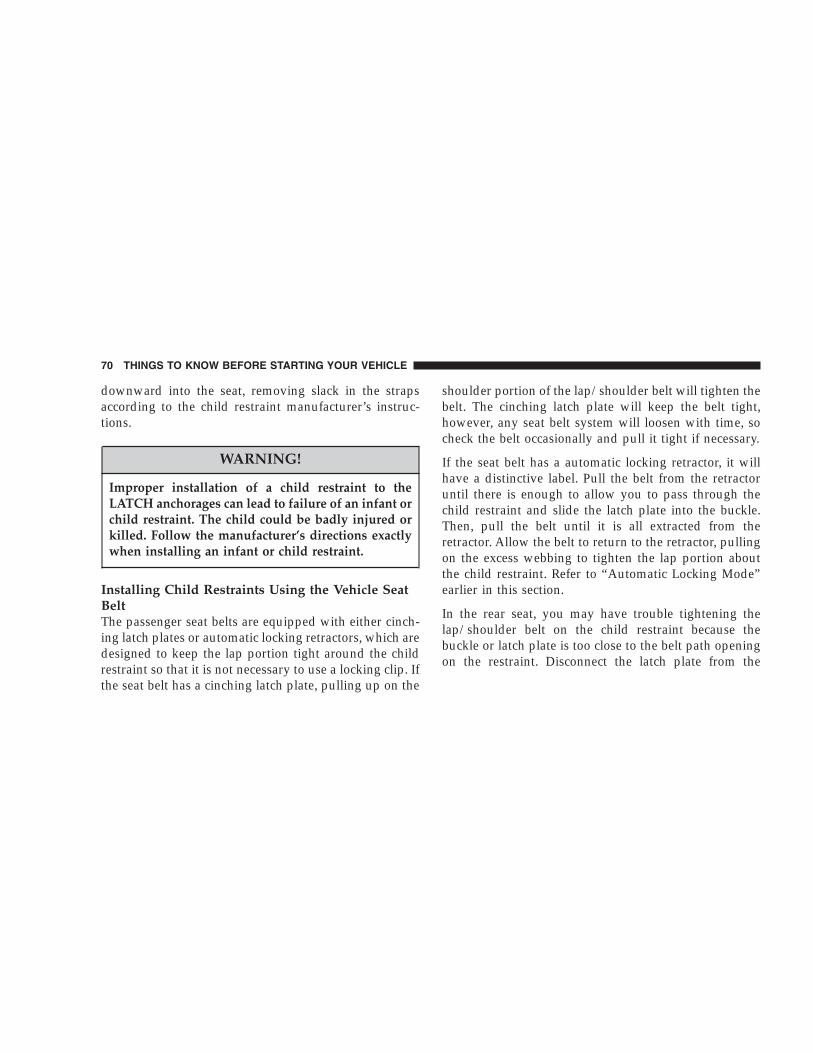
downward into the seat, removing slack in the strapsaccording to the child restraint manufacturer’s instruc-tions.
WARNING!
Improper installation of a child restraint to theLATCH anchorages can lead to failure of an infant orchild restraint. The child could be badly injured orkilled. Follow the manufacturer’s directions exactlywhen installing an infant or child restraint.
Installing Child Restraints Using the Vehicle SeatBeltThe passenger seat belts are equipped with either cinch-ing latch plates or automatic locking retractors, which aredesigned to keep the lap portion tight around the childrestraint so that it is not necessary to use a locking clip. Ifthe seat belt has a cinching latch plate, pulling up on the
shoulder portion of the lap/shoulder belt will tighten thebelt. The cinching latch plate will keep the belt tight,however, any seat belt system will loosen with time, socheck the belt occasionally and pull it tight if necessary.
If the seat belt has a automatic locking retractor, it willhave a distinctive label. Pull the belt from the retractoruntil there is enough to allow you to pass through thechild restraint and slide the latch plate into the buckle.Then, pull the belt until it is all extracted from theretractor. Allow the belt to return to the retractor, pullingon the excess webbing to tighten the lap portion aboutthe child restraint. Refer to “Automatic Locking Mode”earlier in this section.
In the rear seat, you may have trouble tightening thelap/shoulder belt on the child restraint because thebuckle or latch plate is too close to the belt path openingon the restraint. Disconnect the latch plate from the
70 THINGS TO KNOW BEFORE STARTING YOUR VEHICLE

buckle and twist the short buckle-end belt several timesto shorten it. Insert the latch plate into the buckle with therelease button facing out.
If the belt still can’t be tightened, or if by pulling andpushing on the restraint loosens the belt, you may needto do something more. Disconnect the latch plate fromthe buckle, turn the buckle around, and insert the latchplate into the buckle again. If you still can’t make thechild restraint secure, try a different seating position.
To attach a child restraint tether strap:
Route the tether strap over the seat back and attach thehook to the tether anchor located on the back of the seat.For the outboard seating positions, route the tether underthe head restraint between the head restraint posts.
Tether Strap Mounting
THINGS TO KNOW BEFORE STARTING YOUR VEHICLE 71
2

WARNING!
An incorrectly anchored tether strap could lead toincreased head motion and possible injury to thechild. Use only the anchor positions directly behindthe child seat to secure a child restraint top tetherstrap.
Children Too Large for Booster SeatsChildren who are large enough to wear the shoulder beltcomfortably, and whose legs are long enough to bendover the front of the seat when their back is against theseat back should use the lap/shoulder belt in a rear seat.
• Make sure that the child is upright in the seat.
• The lap portion should be low on the hips and as snugas possible.
• Check belt fit periodically. A child’s squirming orslouching can move the belt out of position.
• If the shoulder belt contacts the face or neck, move thechild closer to the center of the vehicle. Never allow achild to put the shoulder belt under an arm.
Transporting PetsAirbags deploying in the front seat could harm your pet.An unrestrained pet will be thrown about and possiblyinjured, or injure a passenger during panic braking or ina collision.
Pets should be restrained in the rear seat in pet harnessesor pet carriers that are secured by seat belts.
72 THINGS TO KNOW BEFORE STARTING YOUR VEHICLE

ENGINE BREAK-IN RECOMMENDATIONSA long break-in period is not required for the engine inyour new vehicle.
Drive moderately during the first 300 miles (500 km).After the initial 60 miles (100 km), speeds up to 50 or 55mph (80 or 90 km/h) are desirable.
While cruising, brief full-throttle acceleration, within thelimits of local traffic laws, contributes to a good break-in.Wide open throttle acceleration in low gear can bedetrimental and should be avoided.
The engine oil installed in the engine at the factory is ahigh quality energy conserving type lubricant. Oilchanges should be consistent with anticipated climateconditions under which vehicle operations will occur.The recommended viscosity and quality grades areshown in Section 7 of this manual. NON-DETERGENTOR STRAIGHT MINERAL OILS MUST NEVER BEUSED.
A new engine may consume some oil during its first fewthousand miles (kilometers) of operation. This should beconsidered as a normal part of the break-in and notinterpreted as an indication of difficulty.
SAFETY TIPS
Exhaust Gas
WARNING!
Exhaust gases can injure or kill. They contain carbonmonoxide (CO) which is colorless and odorless.Breathing it can make you unconscious and caneventually poison you. To avoid breathing (CO)follow the safety tips below.
• Do not inhale exhaust gases. They contain carbonmonoxide, a colorless and odorless gas which can kill.Never run the engine in a closed area, such as a
THINGS TO KNOW BEFORE STARTING YOUR VEHICLE 73
2
garage, and never sit in a parked vehicle with theengine running for a extended period. If the vehicle isstopped in an open area with engine running for morethan a short period, adjust the ventilation system toforce fresh, outside air into the vehicle.
• Guard against carbon monoxide with proper mainte-nance. Have the exhaust system inspected every timethe vehicle is raised. Have any abnormal conditionsrepaired promptly. Until repaired, drive with all sidewindows fully open.
• Always run the climate control in panel or floor modewhen driving with any windows open, even if onlyslightly, to help keep fresh air circulating inside ve-hicle. Otherwise poisonous gases could be drawn intothe vehicle.
Safety Checks You Should Make Inside TheVehicle
Seat BeltsInspect the belt system periodically, checking for cuts,frays and loose parts. Damaged parts must be replacedimmediately. Do not disassemble or modify the system.
Seat belt assemblies must be replaced after an accident ifthey have been damaged (bent retractor, torn webbing,pretensioners, etc.). If there is any question regarding beltor retractor condition, replace the belt.
NOTE: The “Seat Belt Indicator Light” will remain onuntil the driver’s seat belt is buckled.
Airbag Warning LightThe light should come on and remain on for 6 to 8seconds as a bulb check when the ignition switch is firstturned on. If the bulb is not lit during starting, have thesystem checked by an authorized dealer.
74 THINGS TO KNOW BEFORE STARTING YOUR VEHICLE

DefrostersCheck operation by selecting the defrost mode and placethe blower control on high speed. You should feel the airdirected against the windshield.
Safety Checks You Should Make Outside TheVehicle
TiresExamine tires for excessive tread wear or uneven wearpatterns. Check for stones, nails, glass, or other objectslodged in the tread. Inspect for tread cuts or sidewallcracks. Check wheel nuts for tightness and tires (includ-ing spare) for proper pressure.
LightsHave someone observe the operation of all exterior lightswhile you work the controls. Check turn signal and highbeam indicator lights on the instrument panel.
Fluid LeaksCheck area under vehicle after overnight parking for fuel,coolant, oil or other fluid leaks. Also, if gasoline fumesare detected, the cause should be located and correctedimmediately.
THINGS TO KNOW BEFORE STARTING YOUR VEHICLE 75
2


UNDERSTANDING THE FEATURES OF YOUR VEHICLE
CONTENTS
� Mirrors . . . . . . . . . . . . . . . . . . . . . . . . . . . . . . .81
▫ Inside Day/Night Mirror . . . . . . . . . . . . . . . . .81
▫ Inside Automatic Dimming Mirror —If Equipped . . . . . . . . . . . . . . . . . . . . . . . . . .82
▫ Outside Mirrors . . . . . . . . . . . . . . . . . . . . . . .82
▫ Power Remote Control Outside Mirrors —If Equipped . . . . . . . . . . . . . . . . . . . . . . . . . .83
▫ Heated Remote Control Mirrors —If Equipped . . . . . . . . . . . . . . . . . . . . . . . . . .84
▫ Illuminated Vanity Mirrors — If Equipped . . . .84
� Hands–Free Communication (UConnect™) —If Equipped . . . . . . . . . . . . . . . . . . . . . . . . . . . .85
▫ Operation . . . . . . . . . . . . . . . . . . . . . . . . . . . .87
▫ Phone Call Features . . . . . . . . . . . . . . . . . . . .93
▫ UConnect™ System Features . . . . . . . . . . . . . .96
▫ Advanced Phone Connectivity . . . . . . . . . . . . 100
▫ Things You Should Know About YourUConnect™ System . . . . . . . . . . . . . . . . . . . . 102
� Seats . . . . . . . . . . . . . . . . . . . . . . . . . . . . . . . . 108
▫ Front Seat (Manual) Adjustment . . . . . . . . . . . 108
3

▫ Front Seat Adjustment — Recline . . . . . . . . . . 109
▫ Head Restraints . . . . . . . . . . . . . . . . . . . . . . 110
▫ Power Seat Adjuster — If Equipped . . . . . . . . 111
▫ Heated Seats — If Equipped . . . . . . . . . . . . . 112
▫ 65/35 Split Folding Rear Seat . . . . . . . . . . . . . 113
� To Open And Close The Hood . . . . . . . . . . . . . 116
� Lights . . . . . . . . . . . . . . . . . . . . . . . . . . . . . . . 117
▫ Interior Lights . . . . . . . . . . . . . . . . . . . . . . . 117
▫ Front Map/Reading Lights . . . . . . . . . . . . . . 118
▫ Multi-Function Control Lever . . . . . . . . . . . . . 118
▫ Parking Lights, Instrument Panel Lights, AndHeadlights . . . . . . . . . . . . . . . . . . . . . . . . . . 119
▫ High Beam/Low Beam Select Switch . . . . . . . 119
▫ Passing Light . . . . . . . . . . . . . . . . . . . . . . . . 119
▫ Turn Signals . . . . . . . . . . . . . . . . . . . . . . . . . 119
▫ Lights-On Reminder . . . . . . . . . . . . . . . . . . . 120
▫ Battery Saver Feature — Exterior Lights . . . . . 120
▫ Fog Lights — If Equipped . . . . . . . . . . . . . . . 120
▫ Daytime Running Lights — If Equipped . . . . . 120
▫ Light Bar — If Equipped . . . . . . . . . . . . . . . . 121
� Windshield Wipers And Washers . . . . . . . . . . . . 123
▫ Windshield Washers . . . . . . . . . . . . . . . . . . . 124
▫ Mist Feature . . . . . . . . . . . . . . . . . . . . . . . . . 125
▫ Windshield Wiper Operation . . . . . . . . . . . . . 125
▫ Intermittent Wiper System . . . . . . . . . . . . . . . 125
� Tilt Steering Column . . . . . . . . . . . . . . . . . . . . 126
78 UNDERSTANDING THE FEATURES OF YOUR VEHICLE

� Electronic Speed Control . . . . . . . . . . . . . . . . . . 127
▫ To Activate . . . . . . . . . . . . . . . . . . . . . . . . . . 127
▫ To Set At A Desired Speed . . . . . . . . . . . . . . . 128
▫ To Deactivate . . . . . . . . . . . . . . . . . . . . . . . . 128
▫ To Resume Speed . . . . . . . . . . . . . . . . . . . . . 128
▫ To Vary The Speed Setting . . . . . . . . . . . . . . . 128
▫ To Accelerate For Passing . . . . . . . . . . . . . . . 129
� Overhead Console — If Equipped . . . . . . . . . . . 129
▫ Dome/Reading Lights . . . . . . . . . . . . . . . . . . 130
▫ Electronic Vehicle Information Center . . . . . . . 131
▫ Customer Programmable Features . . . . . . . . . 132
▫ Mini-Trip Computer . . . . . . . . . . . . . . . . . . . 135
� Garage Door Opener — If Equipped . . . . . . . . . 139
▫ When Your Vehicle Is New . . . . . . . . . . . . . . 140
▫ Programming Homelink . . . . . . . . . . . . . . . . 141
▫ Gate Operator/Canadian Programming . . . . . 144
▫ Using Homelink . . . . . . . . . . . . . . . . . . . . . . 145
� Power Sunroof — If Equipped . . . . . . . . . . . . . 145
▫ Express Open Feature . . . . . . . . . . . . . . . . . . 147
▫ Sunroof Maintenance . . . . . . . . . . . . . . . . . . . 147
� Power Outlet . . . . . . . . . . . . . . . . . . . . . . . . . . 148
� Cup Holders . . . . . . . . . . . . . . . . . . . . . . . . . . 150
▫ Smoker’s Package — If Equipped . . . . . . . . . . 150
� Cargo Area Features . . . . . . . . . . . . . . . . . . . . . 151
▫ Cargo Light . . . . . . . . . . . . . . . . . . . . . . . . . 151
▫ Retractable Cargo Area Cover — If Equipped . 151
UNDERSTANDING THE FEATURES OF YOUR VEHICLE 79
3

▫ Cargo Tie-Down Hooks . . . . . . . . . . . . . . . . . 152
▫ Cargo Organizer — If Equipped . . . . . . . . . . . 154
� Rear Window Features . . . . . . . . . . . . . . . . . . . 156
▫ Rear Window Wiper/Washer . . . . . . . . . . . . . 156
▫ Rear Window Defroster . . . . . . . . . . . . . . . . . 158
� Roof Luggage Rack . . . . . . . . . . . . . . . . . . . . . 159
80 UNDERSTANDING THE FEATURES OF YOUR VEHICLE

MIRRORS
Inside Day/Night MirrorThe mirror should be adjusted to center on the viewthrough the rear window. A two-point pivot systemallows for horizontal and vertical adjustment of themirror. The mirror should be adjusted while set in theday position (toward windshield).
Annoying headlight glare from vehicles behind you canbe reduced by moving the small control under the mirrorto the night position (toward rear of vehicle).
Adjusting Rear View Mirror
UNDERSTANDING THE FEATURES OF YOUR VEHICLE 81
3

Inside Automatic Dimming Mirror — If EquippedThis mirror automatically adjusts for annoying headlightglare from vehicles behind you. You can turn the featureon or off by pressing the button at the base of the mirror.A light in the button will indicate when the dimmingfeature is activated.
CAUTION!
To avoid damage to the mirror during cleaning,never spray any cleaning solution directly onto themirror. Apply the solution onto a clean cloth andwipe the mirror clean.
Outside MirrorsTo receive maximum benefit, adjust the outside mirrorsto center on the adjacent lane of traffic with a slightoverlap of the view obtained on the inside mirror.
Automatic Dimming Mirror
82 UNDERSTANDING THE FEATURES OF YOUR VEHICLE

WARNING!
Vehicles and other objects seen in the right sideconvex mirror will look smaller and farther awaythan they really are. Relying too much on your rightside mirror could cause you to collide with anothervehicle or other objects. Use your inside mirror whenjudging the size or distance of a vehicle seen in theright side mirror.
Power Remote Control Outside Mirrors — IfEquippedThe controls for the power mirrors are located on thedriver’s door trim panel below the door lock switch.
Set the top switch to the left or right for the left or rightmirror, and set it to the center off position to prevent
accidentally moving a mirror when you are finishedadjusting the mirror. Press one of the four arrows for thedirection you want the mirror to move.
Power Mirror Switches
UNDERSTANDING THE FEATURES OF YOUR VEHICLE 83
3

Heated Remote Control Mirrors — If EquippedThese mirrors are heated to melt frost or ice. Thisfeature is activated whenever you turn on the rear
window defrost.
Illuminated Vanity Mirrors — If EquippedAn illuminated vanity mirror is on the sun visor. To usethe mirror, rotate the sun visor down and swing themirror cover upward. The lights turn on automatically.Closing the mirror cover turns off the lights.
When the ignition is turned off, the light will turn offautomatically (after approximately 8 minutes).
Sun Visor Extension — If EquippedThis feature has a pull out extension on the sun visor forincreased coverage.
Lighted Vanity Mirror
84 UNDERSTANDING THE FEATURES OF YOUR VEHICLE

HANDS–FREE COMMUNICATION (UConnect™) —IF EQUIPPEDUConnect™ is a voice-activated, hands-free, in vehiclecommunications system. UConnect™ allows you to diala phone number with your cellular phone* using simplevoice commands (e.g., �Call � Mike �Work� or �Dial �248-555-1212�). Your cellular phone’s audio is transmittedthrough your vehicle’s audio system; the system willautomatically mute your radio when using the UCon-nect™ system.
NOTE: The UConnect™ system use requires a cellularphone equipped with the Bluetooth �Hands-Free Profile,�version 0.96 or higher.
For UConnect Customer Support call 1-877-855-8400 orvisit the UConnect website (www.chrysler.com/uconnect).
UConnect™ allows you to transfer calls between thesystem and your cellular phone as you enter or exit yourvehicle, and enables you to mute the system’s micro-phone for private conversation.
The UConnect™ phonebook enables you to store up to 32names and four numbers per name. Each language has aseparate 32 name phonebook accessible only in thatlanguage. This system is driven through your Blue-tooth™ Hands-Free profile cellular phone. UConnect™features Bluetooth™ technology - the global standardthat enables different electronic devices to connect toeach other without wires or a docking station, so UCon-nect works no matter where you stow your cellularphone (be it your purse, pocket, or briefcase), as long asyour phone is turned on and has been paired to thevehicle’s UConnect™ system. The UConnect™ systemallows up to seven cellular phones to be linked to system.Only one linked (or paired) cellular phone can be used
UNDERSTANDING THE FEATURES OF YOUR VEHICLE 85
3

with the system at a time. The system is available inEnglish, Spanish, or French languages (as equipped).
The rearview mirror contains the microphone for thesystem and the control buttons that will enable you toaccess the system. The diagram below shows the mirrorwith the appropriate buttons. Individual button behavioris discussed in the �Operation� section.
The UConnect™ system can be used with any Hands-Free Profile certified Bluetooth™ cellular phone. If yourcellular phone supports a different profile (eg., HeadsetProfile), you may not be able to use any UConnect™features. Refer to your cellular service provider or thephone manufacturer for details.
UConnect™ Switches
86 UNDERSTANDING THE FEATURES OF YOUR VEHICLE

The UConnect™ system is fully integrated with thevehicle’s audio system. The volume of the UConnect™system can either be adjusted from the radio volumecontrol knob, or from the steering wheel radio control(right switch), if so equipped.
The radio display will be used for visual prompts fromthe UConnect™ system such as �CELL� or caller ID oncertain radios.
OperationVoice commands can be used to operate the UConnect™system and to navigate through the UConnect™ menustructure. Voice commands are required after mostUConnect™ system prompts. You will be prompted for aspecific command and then guided through the availableoptions.
• Prior to giving a voice command, one must wait forthe voice on beep, which follows the �Ready� promptor another prompt.
• For certain operations, compound commands can beused. For example, instead of saying �Setup� and then�Phone Pairing,� the following compound commandcan be said: �Setup Phone Pairing.�
• For each of the feature explanation in this section, onlythe combined form of the voice command is given.You can also break the commands into parts and sayeach part of the command, when you are asked for it.For example, you can either use the combined formvoice command �Phonebook New Entry,� or you canbreak the combined form command into two voicecommands: �Phonebook� and �New Entry.� Please re-member, the UConnect™ system works best when youtalk in a normal conversational tone, as if speaking tosome one sitting eight feet away from you.
Voice Command TreeRefer to “Voice Tree” at the end of this section.
UNDERSTANDING THE FEATURES OF YOUR VEHICLE 87
3

Help CommandIf you need assistance at any prompt or if you want toknow what your options are at any prompt, say �Help�following the voice on beep. The UConnect™ system willplay all the options at any prompt if you ask for help.
To activate the UConnect™ system from idle, simplypress the ’Phone’ button and follow audible prompts fordirections. All UConnect™ system sessions begin with apress of the ’Phone’ button on the mirror.
Cancel CommandAt any prompt, after the voice on beep, you can say�Cancel� and you will be returned to the main menu.However, in a few instances the system will take youback to the previous menu.
Pair (Link) UConnect™ System to a Cellular PhoneTo begin using your UConnect™ system, you must pairyour compatible Bluetooth™ enabled cellular phone (re-fer to �Introduction� section to learn about the phone
type). To complete the pairing process, you will need toreference your cellular phone owner’s manual. One of thefollowing vehicle specific websites may also providedetailed instructions for pairing with the brand of phonethat you have:
NOTE:• www.chrysler.com/uconnect
• www.dodge.com/uconnect
• www.jeep.com/uconnect
The following are general phone to UConnect™ Systempairing instructions:
• Press the ’Phone’ button to begin.
• After the �Ready� prompt and the following beep, say�Setup Phone Pairing.�
• When prompted, after the voice on beep, say �Pair aPhone.�
88 UNDERSTANDING THE FEATURES OF YOUR VEHICLE

• You will be asked to say a four-digit pin number whichyou will later need to enter into your cellular. You canenter any four-digit pin number. You will not need toremember this pin number after the initial pairingprocess.
• The UConnect™ system will then prompt you to beginthe cellular phone pairing process on your cellularphone. Before attempting to pair phone, please seeyour cellular phone’s user manual (Bluetooth section)for instructions on how to complete this step.
• For identification purposes, you will be prompted togive the UConnect™ system a name for your cellularphone. Each cellular phone that is paired should begiven a unique phone name.
• You will then be asked to give your cellular phone apriority level between 1 and 7, 1 being the highestpriority. You can pair up to seven cellular phones toyour UConnect™ system. However, at any given time,
only one cellular phone can be in use, connected toyour UConnect™ System. The priority allows theUConnect™ system to know which cellular phone touse if multiple cellular phones are in the vehicle at thesame time. For example, if priority 3 and priority 5phones are present in the vehicle, the UConnect™system will use the priority 3 cellular phone when youmake a call. You can select to use a lower prioritycellular phone at any time (refer to �Advanced PhoneConnectivity� section).
Dial by Saying a Number
• Press the ’Phone’ button to begin.
• After the �Ready� prompt and the following beep, say�Dial.�
• System will prompt you to say the number you wantcall.
UNDERSTANDING THE FEATURES OF YOUR VEHICLE 89
3

• For example, you can say �234-567-8901.� The phonenumber that you enter must be of valid length andcombination. The UConnect™ limits the user fromdialing invalid combination of numbers. For example,234-567-890 is nine digits long, which is not a validphone number - the closest valid phone number hasten digits.
• The UConnect™ system will confirm the phone num-ber and then dial. The number will appear in thedisplay of certain radios.
Call by Saying a Name
• Press the “Phone” button to begin.
• After the �Ready� prompt and the following beep, say�Call.�
• System will prompt you to say the name of the personyou want call.
• After the �Ready� prompt and the following beep, saythe name of the person you want to call. For example,you can say �John Doe,� where John Doe is a previ-ously stored name entry in the UConnect™ phone-book. Refer to section �Add Names to Your UCon-nect™ Phonebook,� to learn how to store a name in thephonebook.
• The UConnect™ system will confirm the name andthen dial the corresponding phone number, whichmay appear in the display of certain radios.
Add Names to Your UConnect™ Phonebook
NOTE: Adding names to phonebook is recommendedwhen vehicle is not in motion.
• Press the “Phone” button to begin.
• After the �Ready� prompt and the following beep, say�Phonebook New Entry.�
90 UNDERSTANDING THE FEATURES OF YOUR VEHICLE

• When prompted, say the name of the new entry. Use oflong names helps the voice recognition and is recom-mended. For example, say �Robert Smith� or �Robert�instead of �Bob.�
• When prompted, enter the number designation (e.g.:�Home,� �Work,� �Mobile,� or �Pager�). This will allowyou to store multiple numbers for each phonebookentry, if desired.
• When prompted, recite the phone number for thephonebook entry that you are adding.
After you are finished adding an entry into the phone-book, you will be given the opportunity to add morephone numbers to the current entry or to return to themain menu.
The UConnect™ system will allow you to enter up to 32names in the phonebook with each name having up to
four associated phone numbers and designations. Eachlanguage has a separate 32 name phonebook accessibleonly in that language.
Edit Entries in the UConnect™ Phonebook
NOTE: Adding names to phonebook is recommendedwhen vehicle is not in motion.
• Press the ’Phone’ button to begin.
• After the �Ready� prompt and the following beep, say�Phonebook Edit.�
• You will then be asked for the name of the phonebookentry that you wish to edit.
• Next, choose the number designation (home, work,mobile, or pager) that you wish to edit.
• When prompted, recite the new phone number for thephonebook entry that you are editing.
UNDERSTANDING THE FEATURES OF YOUR VEHICLE 91
3

After you are finished editing an entry in the phonebook,you will be given the opportunities to edit another entryin the phonebook, call the number you just edited, orreturn to the main menu.
�Phonebook Edit� can be used to add another phonenumber to a name entry that already exists in thephonebook. For example, the entry John Doe may have amobile and a home number, but you can add John Doe’swork number later using the �Phonebook Edit� feature.
Delete Entries in the UConnect™ Phonebook
• Press the ’Phone’ button to begin.
• After the �Ready� prompt and the following beep, say�Phonebook Delete.�
• After you enter the Phonebook Delete menu, you willthen be asked for the name of the entry that you wishto delete. You can either say the name of a phonebookentry that you wish to delete or you can say �List
Names� to hear a list of the entries in the phonebookfrom which you choose. To select one of the entriesfrom the list, press the �Voice Recognition� buttonwhile the UConnect™ system is playing the desiredentry and say �Delete.�
• After you enter the name, the UConnect™ system willask you which designation you wish to delete: home,work, mobile or pager. Say the designation you wishto delete.
After confirmation, the phonebook entries will be de-leted. Note that only the phonebook in the currentlanguage is deleted.
Delete All Entries in the UConnect™ Phonebook
• Press the ’Phone’ button to begin.
• After the �Ready� prompt and the following beep, say�Phonebook Erase All.�
92 UNDERSTANDING THE FEATURES OF YOUR VEHICLE
• The UConnect™ system will ask you to verify that youwish to delete all the entries from the phonebook.
• After confirmation, the phonebook entries will bedeleted.
List All Names in the UConnect™ Phonebook
• Press the ’Phone’ button to begin.
• After the �Ready� prompt and the following beep, say�Phonebook List Names.�
• The UConnect™ system will play the names of all thephonebook entries.
• To call one of the names in the list, press the �VoiceRecognition’ button during the playing of the desiredname and say �Call�. NOTE: the user can also exercise�Edit� or �Delete� operations at this point.
• The UConnect™ system will then prompt you as tonumber designation you wish to call.
• The selected number will be dialed.
Phone Call FeaturesThe following features can be accessed through theUConnect™ system if the feature(s) are available on yourcellular service plan. For example, if your cellular serviceplan provides three-way calling, this feature can beaccessed through the UConnect™ system. Check withyour cellular service provider for the features that youhave.
Answer or Reject an Incoming Call - No CallCurrently in ProgressWhen you receive a call on your cellular phone, theUConnect™ system will interrupt the vehicle audiosystem, if on, and will ask if you would like to answer thecall. To reject the call, press and hold the ’Phone’ buttonuntil you hear a single beep indicating that the incomingcall was rejected.
UNDERSTANDING THE FEATURES OF YOUR VEHICLE 93
3

Answer or Reject an Incoming Call - CallCurrently in ProgressIf a call is currently in progress and you have anotherincoming call, you will hear the same network tones forcall waiting that you normally hear when using your cellphone. Press the ’Phone’ button to place the current callon hold and answer the incoming call. NOTE: TheUConnect™ system compatible phones in market todaydo not support rejecting an incoming call when anothercall is in progress. Therefore, the user can only eitheranswer an incoming call or ignore it.
Making a Second Call while Current Call inProgressTo make a second call while you are currently in a call,press the ’Voice Recognition’ button and say �Dial� or�Call� followed by the phone number or phonebook entryyou wish to call. The first call will be on hold while the
second call is in progress. To go back to the first call, referto section �Toggling Between Two Calls.� To combine twocalls, refer to section �Conference Call.�
Place/Retrieve a Call from HoldTo put a call on hold, press the �Phone’ button until youhear a single beep which will indicate that the call hasbeen placed on hold. To bring the call back from hold,press and hold the �Phone’ button until you hear a singlebeep.
Toggling Between CallsIf two calls are in progress (one active and one on hold),press the ’Phone’ button until you hear a single beepindicating that the active and hold status of the two callshave switched. Only one call can be placed on hold at onetime.
94 UNDERSTANDING THE FEATURES OF YOUR VEHICLE

Conference CallWhen two calls are in progress (one active and one onhold), press and hold the ’Phone’ button until you hear adouble beep indicating that the two calls have beenjoined into one conference call.
Three-Way CallingTo initiate three-way calling, press the ’Voice Recogni-tion’ button while a call is in progress and make a secondphone call as described in section �Making a Second Callwhile Current Call in Progress.� After the second call hasestablished, press and hold the ’Phone’ button until youhear a double beep indicating that the two calls havebeen joined into one conference call.
Call TerminationTo end a call in progress, momentarily press the �Phone’button. Only the active call(s) will be terminated and ifthere is a call on hold, it will become the new active call.
Redial
• Press the ’Phone’ button to begin.
• After the �Ready� prompt and the following beep, say�Redial.�
• The UConnect™ system will call the last number thatwas dialed on your cellular phone. Note: this may not bethe last number dialed from the UConnect™ system.
Call ContinuationCall continuation is progression of a phone call onUConnect™ system after the vehicle ignition key hasbeen switched to off. Call continuation functionalityavailable on the vehicle can be any one of three types:
• After ignition key is switched off, a call can continueon the UConnect™ system either until the call ends oruntil the vehicle battery condition dictates cessation ofthe call on the UConnect™ system and transfer of thecall to the mobile phone.
UNDERSTANDING THE FEATURES OF YOUR VEHICLE 95
3

• After ignition key is switched to off, a call can continueon the UConnect™ system for certain duration, afterwhich the call is automatically transferred from theUConnect™ system to the mobile phone.
• An active call is automatically transferred to themobile phone after ignition key is switched to off.
UConnect™ System Features
Language SelectionTo change the language that the UConnect™ system isusing,
• Press the ’Phone’ button to begin.
• After the �Ready� prompt and the following beep, saythe name of the language you wish to switch to(English, Espanol, or Francais, if so equipped).
• Continue to follow the system prompts to completelanguage selection.
After selecting one of the languages, all prompts andvoice commands will be in that language.
NOTE: After every UConnect™ language change op-eration, only the language specific 32 name phonebook isusable. The phone pairing is not language specific andusable across all languages.
Emergency AssistanceIf you are in an emergency and the mobile phone isreachable:
• Pick up the phone and manually dial the emergencynumber for your area.
If the phone is not reachable and the UConnect™ systemis operational, you may reach the emergency number asfollows:
• Press the ’Phone’ button to begin.
96 UNDERSTANDING THE FEATURES OF YOUR VEHICLE

• After the �Ready� prompt and the following beep, say�Emergency� and the UConnect™ system will instructthe paired cellular phone to call the emergency num-ber. This feature is only supported in the USA.
NOTE: The emergency number dialed is based on theCountry where the vehicle is purchased (911 for USA/Canada and 060 for Mexico). The number called may notbe applicable with the available cellular service and area.
The UConnect™ system does slightly lower your chancesof successfully making a phone call as to that for the cellphone directly.
Your phone must be turned on and paired to the UCon-nect™ system to allow use of this vehicle feature inemergency situations when the cell phone has networkcoverage and stays paired to the UConnect™ system.
Towing AssistanceIf you need towing assistance,
• Press the ’Phone’ button to begin.
• After the �Ready� prompt and the following beep, say�Towing Assistance.�
NOTE: The Towing Assistance number dialed is basedon the Country where the vehicle is purchased (1-800-528-2069 for USA, 1-877-213-4525 for Canada, 55-14-3454for Mexico city and 1-800-712-3040 for outside Mexicocity in Mexico).
Please refer to the 24-Hour Towing Assistance coveragedetails in the DaimlerChrysler Corporation 24-HourTowing Assistance Program Guide.
UNDERSTANDING THE FEATURES OF YOUR VEHICLE 97
3

PagingTo learn how to page, refer to section �Working withAutomated Systems.� Paging works properly except forpagers of certain companies which time-out a little toosoon to work properly with the UConnect™ system.
Voice Mail CallingTo learn how to access your voice mail, refer to section�Working with Automated Systems.�
Working with Automated SystemsThis method is designed to be used in instances whereone generally has to press numbers on the cellular phonekeypad while navigating through an automated tele-phone system.
You can use your UConnect™ system to access a voice-mail system or an automated service, such as, pagingservice or automated customer service. Some servicesrequire immediate response selection, in some instances,that may be too quick for use of UConnect™ system.
When calling a number with your UConnect™ systemthat normally requires you to enter in a touch-tonesequence on your cellular phone keypad, you can pushthe ’Voice Recognition’ button and say the sequence youwish to enter followed by the word �Send.� For example,if required to enter your pin number followed with apound 3 7 4 6 #, you can press the ’Voice Recognition’button and say �3 7 4 6 # Send.� Saying a number, orsequence of numbers, followed by �Send� is also to beused to navigate through an automated customer servicecenter menu structure and to leave a number on a pager.
Barge In - Overriding PromptsThe ’Voice Recognition’ button can be used when youwish to skip part of a prompt and issue your voicerecognition command immediately. For example, if aprompt is playing �Would you like to pair a phone, cleara�,� you could press the ’Voice Recognition’ button andsay �Pair a Phone� to select that option without having tolisten to the rest of the voice prompt.
98 UNDERSTANDING THE FEATURES OF YOUR VEHICLE

Turning Confirmation Prompts On/OffTurning confirmation prompts off will stop the systemfrom confirming your choices (e.g. the UConnect™ sys-tem will not repeat a phone number before you dial it).
• Press the ’Phone’ button to begin.
• After the �Ready� prompt and the following beep, say�Setup Confirmations.� The UConnect™ system willplay the current confirmation prompt status and youwill be given the choice to change it.
Phone and Network Status IndicatorsThe UConnect™ system will provide notification toinform you if your cellular phone is in roaming status,has low signal strength, or has a low battery when youare trying to place a phone call.
Dialing Using the Cellular Phone KeypadYou can dial a phone number with your cellular phonekeypad and still use the UConnect™ system (whiledialing via the cell phone keypad, the user must exercisecaution and take precautionary safety measures). Bydialing a number with your paired Bluetooth™ cellularphone, the audio will be played through your vehicle’saudio system. The UConnect™ system will work thesame as if you dial the number using voice recognition.
NOTE: Certain brands of mobile phones do not send thedial ring to the UConnect™ system to play it on thevehicle audio system, so you will not hear it. Under thissituation, after successfully dialing a number, the usermay feel that the call did not go through even though thecall is in progress. Once your call is answered, you willhear the audio.
UNDERSTANDING THE FEATURES OF YOUR VEHICLE 99
3

Mute/Un-mute (Mute off)When you mute the UConnect™ system, you will still beable to hear the conversation coming from the otherparty, but the other party will not be able to hear you. Inorder to mute the UConnect™ system:
• Press the ’Voice Recognition’ button.
• After the �Ready� prompt and the following beep, say�Mute.�
In order to un-mute the UConnect™ system:
• Press the ’Voice Recognition’ button.
• After the �Ready� prompt and the following beep, say�Mute-off.�
Information ServiceWhen using AT&T Wireless Service, dialing to phonenumber �#121,� you can access voice activated automatedsystem to receive news, weather, stocks, traffic, etc.related information.
Advanced Phone Connectivity
Transfer Call to and from Cellular PhoneThe UConnect™ system allows on going calls to betransferred to your cellular phone to the UConnect™system without terminating the call. To transfer an ongo-ing call from your UConnect™ paired cellular phone tothe UConnect™ system or vice-versa, press the ’VoiceRecognition’ button and say �Transfer Call.�
100 UNDERSTANDING THE FEATURES OF YOUR VEHICLE

Connect or Disconnect Link Between theUConnect™ System and Cellular PhoneYour cellular phone can be paired with many differentelectronic devices, but can only be actively �connected�with one electronic device at a time.
If you would like to connect or disconnect the Blue-tooth™ connection between a UConnect™ paired cellularphone and the UConnect™ system, follow the instructiondescribed in your cellular phone user’s manual.
List Paired Cellular Phone Names
• Press the ’Phone’ button to begin.
• After the “Ready” prompt and the following beep, say“Setup Phone pairing”.
• When prompted, say �List Phones�.
• The UConnect™ system will play the phone names ofall paired cellular phones in order from the highest tothe lowest priority. To “select” or “delete” a pairedphone being announced, press the �Voice recognition’button and say “Select” or “Delete”. Also, see next twosections for alternate way of doing this.
Select another Cellular PhoneThis feature allows you to select and start using anotherphone with the UConnect™ system. The phone musthave been previously paired to the UConnect™ systemthat you want to use it with.
• Press the ’Phone’ button to begin.
• After the �Ready� prompt and the following beep, say�Setup Select Phone.�
• The phone names (along with priority numbers) willbe played.
UNDERSTANDING THE FEATURES OF YOUR VEHICLE 101
3

• When prompted say the priority number of the cellu-lar phone you wish to select. You can also press the�Voice Recognition’ button anytime while the list isbeing played and say the priority number.
• The selected phone will be used for the next phonecall. If the selected phone is not available, the UCon-nect™ system will return to using the highest priorityphone present in or near (approximately with in 30feet) the vehicle.
Delete UConnect™ Paired Cellular Phones
• Press the ’Phone’ button to begin.
• After the �Ready� prompt and the following beep, say�Setup Phone Pairing.�
• At the next prompt, say �Delete.�
• The phone names (along with priority numbers) willbe played.
• When prompted say the priority number of the cellu-lar phone (or “All” to delete all phones) you wish todelete. You can also press the �Voice Recognition’button anytime while the list is being played and saythe priority number.
Things You Should Know About Your UConnect™System
Voice Recognition (VR)
• Always wait for the beep before speaking.
• Speak normally, without pausing, just as you wouldspeak to a person sitting approximately eight (8) feetaway from you.
• Make sure that no one other than you is speakingduring a voice recognition period.
102 UNDERSTANDING THE FEATURES OF YOUR VEHICLE

• Performance is maximized under:
• low-to-medium blower setting,
• low-to-medium vehicle speed,
• low road noise,
• smooth road surface,
• fully closed windows,
• dry weather condition.
• Even though the system is designed for users speakingin North American English and Spanish accents, thesystem may not always work for some.
• When navigating through an automated system, suchas, voice mail, or when sending a page, at the end ofspeaking the digit string, make sure to say �send.�
• Storing names in phonebook when vehicle is not inmotion is recommended.
• It is not recommended to store similar soundingnames in the UConnect™ phonebook.
• UConnect™ phonebook name tag recognition rate isoptimized for the person who stored the name in thephonebook.
• You can say �O� (letter �O�) for �0� (zero). �800� must bespoken �eight-zero-zero.�
• Even though international dialing for most numbercombinations is supported, some shortcut dialingnumber combinations may not be supported.
Far End Audio Performance
• Audio quality is maximized under:
• low-to-medium blower setting,
• low-to-medium vehicle speed,
• low road noise,
UNDERSTANDING THE FEATURES OF YOUR VEHICLE 103
3

• smooth road surface,
• fully closed windows, and
• dry weather condition.
• Operation from driver seat.
• Performance, such as, audio clarity, echo. and loud-ness to a large degree, rely on the phone and network,and not the UConnect™ system.
• Echo at far end can sometime be reduced by loweringthe in-vehicle audio volume.
Bluetooth Communication LinkCellular phones have been found to occasionally looseconnection to the UConnect™ system. When this hap-pens, the connection can generally be re-established byswitching the phone off/on. Your cell phone is recom-mended to remain in Bluetooth �on� mode.
ResetIn rare instances, it may be necessary to reset the UCon-nect™ system. The reset feature is exercised by pressingand holding the ’UConnect™ ’ and ’Voice Recognition’buttons simultaneously for 15 seconds. Normally, you donot need to exercise this feature.
Power-UpAfter switching ignition key from off to either On or ACCposition, or after a reset, you must wait at least five (5)seconds prior to using the system.
104 UNDERSTANDING THE FEATURES OF YOUR VEHICLE

UNDERSTANDING THE FEATURES OF YOUR VEHICLE 105
3

106 UNDERSTANDING THE FEATURES OF YOUR VEHICLE

UNDERSTANDING THE FEATURES OF YOUR VEHICLE 107
3

North American EnglishPrimary Alternate(s)Zero OhAdd location Add newAll All of themConfirmation prompts Confirmations promptsDelete a name DeleteLanguage Select languageList names List allList paired phones List phonesPager BeeperPhone pairing PairingPhonebook Phone bookReturn to main menu Return. Main menuSelect phone selectSet up Phone settings phone set
up
SEATS
Front Seat (Manual) AdjustmentMove the seat forward or rearward using the adjustmentbar. Lift up on the bar located on the front of the seat nearthe floor. Position the seat and be sure the latch engagesfully.
Manual Seat Adjustment
108 UNDERSTANDING THE FEATURES OF YOUR VEHICLE

Using body pressure, move forward and rearward on theseat to be sure the seat adjusters have latched.
WARNING!
• Adjusting a seat while the vehicle is moving isdangerous. The sudden movement of the seatcould cause you to lose control. The seat beltmight not be properly adjusted and you could beinjured. Adjust any seat only while the vehicle isparked.
• Do not ride with the seatback reclined so that theseat belt is no longer resting against your chest. Ina collision you could slide under the seat belt andbe seriously or even fatally injured. Use the re-cliner only when the vehicle is parked.
Front Seat Adjustment — ReclineTo adjust the seatback, lift the lever located on theoutboard side of the seat, lean back, and release the leverat the desired position. To return the seatback, lift thelever, lean forward, and release the lever.
Recline Control Lever
UNDERSTANDING THE FEATURES OF YOUR VEHICLE 109
3

Head RestraintsHead restraints can reduce the risk of whiplash injury inthe event of impact from the rear. Adjustable headrestraints should be adjusted so that the upper edge is ashigh as practical. The head restraints have a lockingbutton that must be pushed inward to lower the headrestraint. The restraints may be raised without pushing inthe button.
Adjustable Head Restraints
110 UNDERSTANDING THE FEATURES OF YOUR VEHICLE

Power Seat Adjuster — If Equipped
WARNING!
Do not ride with the seatback reclined so that theseat belt is no longer resting against your chest. In acollision you could slide under the seat belt and beseriously or even fatally injured. Use the reclineronly when the vehicle is parked.
6–Way Power Seat with Manual ReclinerThe seat switch is on the outboard side of the seat nearthe floor. Use this switch to move the seat up or down,forward or rearward, or to tilt the seat.
Power Seat Switches
UNDERSTANDING THE FEATURES OF YOUR VEHICLE 111
3
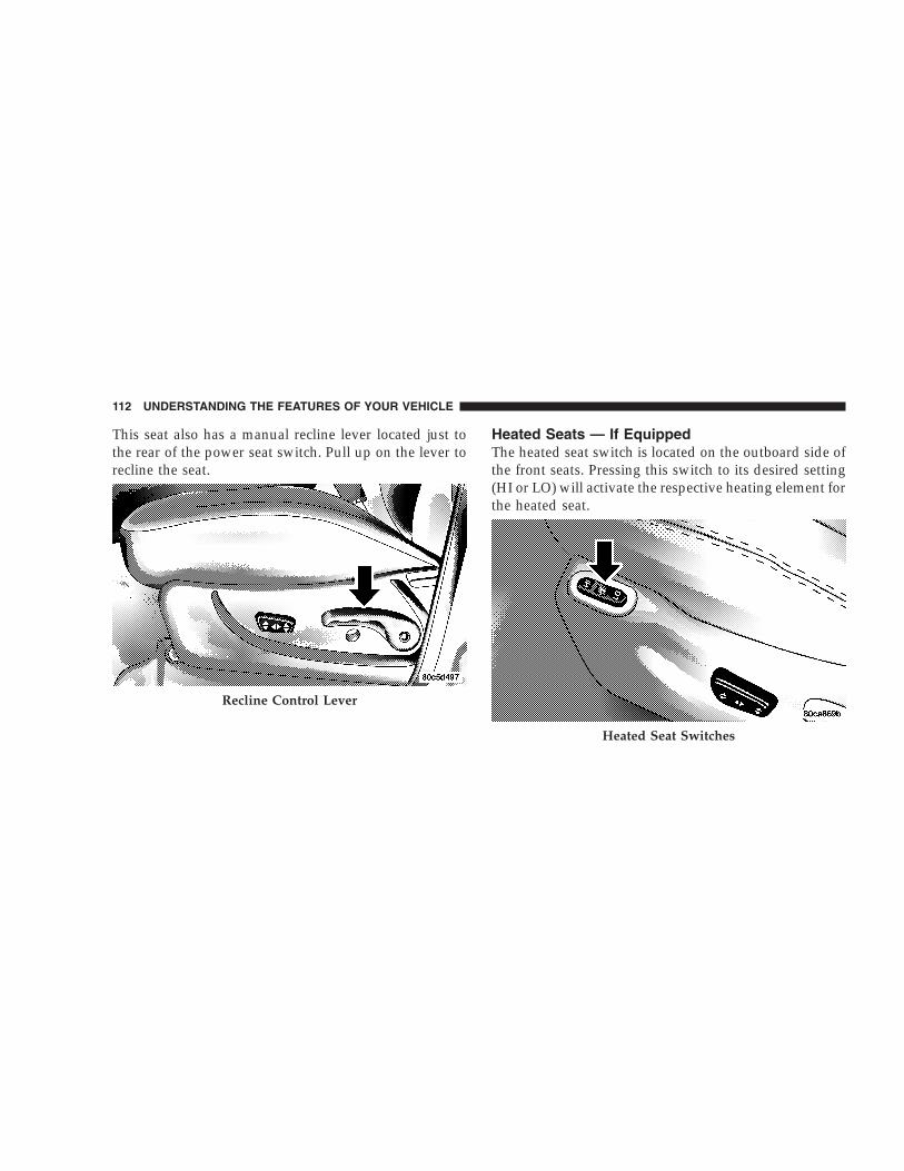
This seat also has a manual recline lever located just tothe rear of the power seat switch. Pull up on the lever torecline the seat.
Heated Seats — If EquippedThe heated seat switch is located on the outboard side ofthe front seats. Pressing this switch to its desired setting(HI or LO) will activate the respective heating element forthe heated seat.
Recline Control Lever
Heated Seat Switches
112 UNDERSTANDING THE FEATURES OF YOUR VEHICLE

Once the heated seat switch is activated, depressing it asecond time will de-activate it.
65/35 Split Folding Rear SeatTo provide additional storage area, each rear seat can befolded flat to allow for extended cargo space and stillmaintain some rear seating room.
NOTE: Prior to folding the rear seat, it may be necessaryto reposition the front seat to it’s mid-track position.
Also, be sure that the front seats are fully upright andpositioned forward. This will allow the rear seat to folddown easily.
WARNING!
• It is extremely dangerous to ride in a cargo area,inside or outside of a vehicle. In a collision,people riding in these areas are more likely to beseriously injured or killed.
• Do not allow people to ride in any area of yourvehicle that is not equipped with seats and seatbelts.
• Be sure everyone in your vehicle is in a seat andusing a seat belt properly.
UNDERSTANDING THE FEATURES OF YOUR VEHICLE 113
3

To fold the 65/35 rear seat, perform the followingsteps:
1. Locate the seatback release handle on the outboard topside of each rear seatback; lift up on the handle, androtate the lever forward until the seatback releases. Foldthe seatback completely forward.
NOTE: When lifting up on the release handle, theseatback will release easier if you do not pull forward onthe seatback; only lift up on the release handle until theseatback disengages, then fold the seat forward.
When the seatback is folded completely forward, thehead restraints should be flush against the seat cushion.Rear Seat Release
Folding Rear Seat
114 UNDERSTANDING THE FEATURES OF YOUR VEHICLE

To restore the 65/35 rear seat to the uprightposition perform the following steps:Raise the seatback and lock it into place. If interferencefrom the cargo area prevents the seatback from fullylocking, you will have difficulty returning the seat to itsproper position. The seat release handle will be flushwith the seatback when the seat is fully latched.
NOTE: If the rear seatback is not fully latched, thecenter shoulder belt will not be able to be extended foruse. If you cannot extend the center shoulder belt, pleasemake sure your seatback is fully latched.
WARNING!
Be certain that the seatback is securely locked intoposition. If the seatback in not securely locked intoposition the seat will not provide the proper stabilityfor child seats and/or passengers. An improperlylatched seat could cause serious injury.
UNDERSTANDING THE FEATURES OF YOUR VEHICLE 115
3

TO OPEN AND CLOSE THE HOODTo open the hood, two latches must be released. First pullthe hood release lever inside your vehicle located underthe left side of the instrument panel.
Then, reach under the hood and slide the safety latch tothe right and lift the hood.
To prevent possible damage, do not slam the hood toclose it. Lower the hood until it is open approximately 12inches (30 cm) and then push hood closed. This shouldHood Release Lever
Underhood Safety Latch
116 UNDERSTANDING THE FEATURES OF YOUR VEHICLE

secure both latches. Never drive your vehicle unless thehood is fully closed, with both latches engaged.
WARNING!
If the hood is not fully latched, it could fly up whenthe vehicle is moving and block your forward vision.Be sure all hood latches are latched fully beforedriving.
LIGHTS
Interior LightsThe overhead lights will come on when a door is opened,and when the rotating ring on the multi-function controllever is in a position other than OFF. They may also beturned on by rotating the control for the dimmer switchon the multi-function control lever fully upward or bypressing the “Unlock” button on the keyfob.
The overhead lights will automatically turn off in about 8minutes if a door is left open or the dimmer control is leftin the dome light position. Turn the ignition switch ON torestore the overhead light operation.
Rear Cargo LightThe rear cargo light includes an independent “On/Off”switch, which when “off” will not allow the illuminationof any interior lighting when the rear swing gate orflipper glass is opened. All other methods of turning theinterior lighting on/off will function normally regardlessof the rear cargo light switch position.
Dimmer ControlWith the park lights or headlights on, rotating the controlfor the dimmer switch on the multi-function control leverupward will increase the brightness of the instrumentpanel lights. Rotating the control completely upwardturns on the dome light.
UNDERSTANDING THE FEATURES OF YOUR VEHICLE 117
3

Daytime Brightness FeatureCertain components (odometer, radio, etc.) can be illumi-nated at full brightness during the daytime. This can behelpful when driving with your headlights on during thedaytime such as in a parade or a funeral procession. Toactivate this feature, rotate the multi-function controllever one detent lower than the dome light.
Front Map/Reading Lights
These lights are mounted in the overhead console. Eachlight can be turned on by pressing the recessed area of thelens. To turn these lights off, press the recessed area of thelens a second time.
Multi-Function Control LeverThe multi-function control lever controls the operation ofthe park lights, headlights, headlight beam selection,passing light, fog lights, instrument panel light dimming,and turn signals.
Multi-Function Control Lever
118 UNDERSTANDING THE FEATURES OF YOUR VEHICLE

Parking Lights, Instrument Panel Lights, andHeadlightsTurn the end cap of the multi-function control lever to thefirst detent for parking lights and instrument panellights. Turn to the second detent for headlight operation.
To change the brightness of the instrument panel lights,rotate the center portion of the multi-function controllever up or down.
High Beam/Low Beam Select SwitchPull the multi-function control lever towards you toswitch the headlights to HIGH beam. Pull the multi-function control lever a second time to switch the head-lights to LOW beam. The “High Beam Indicator Light”will illuminate when the high beams are on.
Passing LightYou can signal another vehicle with your headlights bylightly pulling the multi-function control lever towardthe steering wheel. This will cause the headlights to turnon at high beam and remain on until the lever is released.The “High Beam Indicator Light” will illuminate whenthe high beams are on.
Turn SignalsMove the multi-function control lever up or down andthe arrows on each side of the instrument cluster flash toshow proper operation of the front and rear turn signallights. You can signal a lane change by moving the leverpartially up or down without moving beyond the detent.
If either light flashes at a very fast rate, check for adefective outside light bulb. If an indicator fails to lightwhen the lever is moved, it would suggest that the fuseor indicator is defective.
UNDERSTANDING THE FEATURES OF YOUR VEHICLE 119
3
NOTE: A tone will chime if the turn signals are left onfor more than 2 miles (3.2 km).
Lights-On ReminderA chime will sound if the driver’s door is left open, andthe headlights or parking lights are left on.
Battery Saver Feature — Exterior LightsIf the park lights, headlights, fog lights, or high beams areleft on when the ignition switch is in the OFF position,the battery saver feature will automatically turn off theexterior lights after eight minutes. Normal operation willresume when the ignition is turned ON or when theswitch is turned to another position.
Fog Lights — If EquippedThe front fog light switch is in the multi-functioncontrol lever. To activate the front fog lights, turnon the park or low beam headlights and pull out
the end of the lever. The “Fog Light Indicator Light” willilluminate when the fog lights are on.
NOTE: The fog lights will only operate with the parklights or the headlights on low beam. Selecting highbeam headlights will turn off the fog lights.
Daytime Running Lights — If EquippedThe headlights come on at a low intensity level after theengine has started. They will turn off when the vehicle isturned off, when the headlights are switched on, or whenthe parking brake is set.
120 UNDERSTANDING THE FEATURES OF YOUR VEHICLE
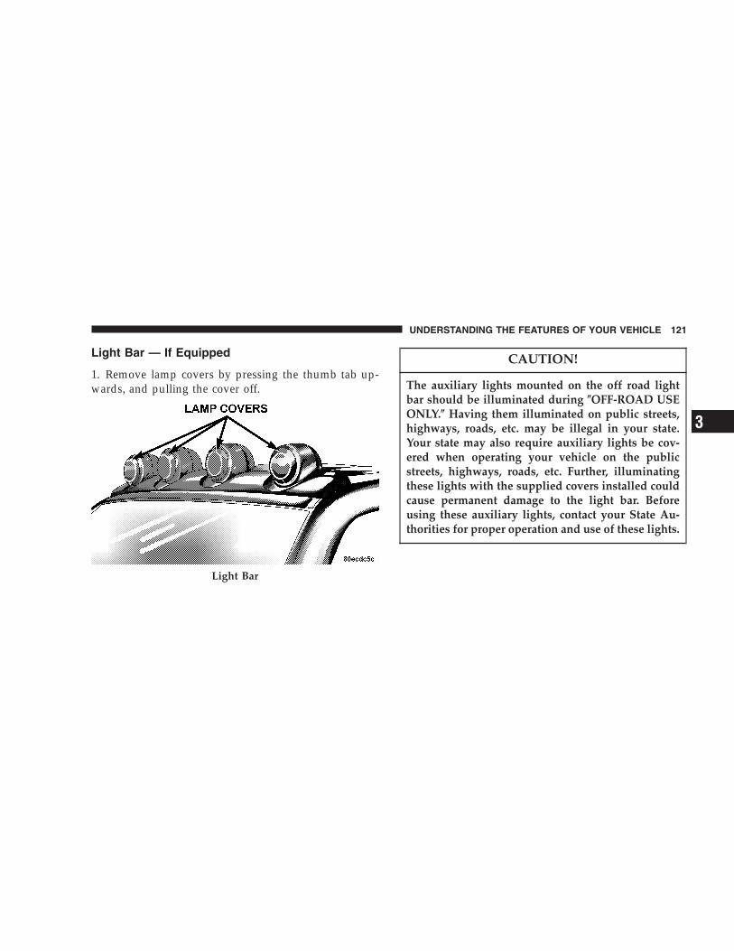
Light Bar — If Equipped
1. Remove lamp covers by pressing the thumb tab up-wards, and pulling the cover off.
CAUTION!
The auxiliary lights mounted on the off road lightbar should be illuminated during �OFF-ROAD USEONLY.� Having them illuminated on public streets,highways, roads, etc. may be illegal in your state.Your state may also require auxiliary lights be cov-ered when operating your vehicle on the publicstreets, highways, roads, etc. Further, illuminatingthese lights with the supplied covers installed couldcause permanent damage to the light bar. Beforeusing these auxiliary lights, contact your State Au-thorities for proper operation and use of these lights.
Light Bar
UNDERSTANDING THE FEATURES OF YOUR VEHICLE 121
3

2. With the ignition in the ON position, press the buttonto turn on the light bar (located on the instrument panelto the left of the steering column). Press the button againto turn off the light bar.
An indicator light in the instrument cluster will illumi-nate when the light bar has been activated.
To reinstall lamp covers, insert the tab under the topcenter lip of the lamp housing. Rotate the cover untilsnap fit is aligned with notch in the bottom center of thehousing. Push cover until it is securely snapped (flush) inthe housing.
Light Bar Switch
122 UNDERSTANDING THE FEATURES OF YOUR VEHICLE

WINDSHIELD WIPERS AND WASHERSThe wipers and washers are operated by a switch on thecontrol lever. This control lever is located on the rightside of the steering column. For front wiper operation,turn the control lever end cap upward to select thedesired wiper speed.
Windshield Wiper/Washer Switch
UNDERSTANDING THE FEATURES OF YOUR VEHICLE 123
3

Windshield WashersTo use the washer, pull the lever toward you and holdwhile spray is desired. If the lever is pulled while in thedelay range, the wiper will operate for two wipe cyclesafter the lever is released, and then resume the intermit-tent interval previously selected.
NOTE: If vehicle is equipped with the optional Elec-tronic Vehicle Information Center (EVIC) in the overheadconsole, all warnings including “door”, “GATE”,“GLASS”, and “LOWASH” will only be displayed in theEVIC display (not in the instrument cluster). For addi-tional information, refer to “Overhead Console — IfEquipped” in Section 3.
The vacuum fluorescent (VF) display located in theodometer area displays the word “LOWASH” when thewasher solvent needs to be refilled. If the vehicle is notmoving, when a low washer fluid condition is detected,the VF display will show the word “LOWASH” and then
show the odometer/trip odometer mileage (each for 2seconds). The display will continue to cycle.
If any other active warnings including “door”, “GATE”,or “GLASS” are present, they will be shown in the VFdisplay and will continue to cycle. If the vehicle startsmoving, two single chimes will occur (one chime for eachcomplete display cycle). After this, the display willcontinue to sequence. After fifteen “LOWASH” se-quences, the VF display will no longer provide thiswarning.
If the trip/reset button is pressed while the VF warningsare being displayed, the VF display will revert back toonly displaying the odometer/trip odometer mileage.Once the warning is removed from the display, it will notreturn for the duration of the ignition cycle.
If the lever is pulled while in the OFF position, the wiperswill operate for several wipe cycles, then turn off.
124 UNDERSTANDING THE FEATURES OF YOUR VEHICLE

Mist FeaturePush down on the wiper lever to activate a single wipe toclear off road mist or spray from a passing vehicle. Aslong as the lever is held down, the wipers will continueto operate.
CAUTION!
In cold weather, always turn off the wiper switchand allow the wipers to return to the park positionbefore turning off the engine. If the wiper switch isleft on and the wipers freeze to the windshield,damage to the wiper motor may occur when thevehicle is restarted.
Windshield Wiper OperationTurn the control lever end cap upward to the middlemark (sixth detent) for Low speed wiper operation, or tothe upper mark (seventh detent) for High speed opera-tion.
Intermittent Wiper System
Use the intermittent wiper when weather conditionsmake a single wiping cycle, with a variable pause be-tween cycles, desirable. Move the control lever to any ofthe first five wiper switch positions by turning the endcap of the control lever. The delay can be regulated froma maximum of approximately 18 seconds between cycles,to a cycle every second.
UNDERSTANDING THE FEATURES OF YOUR VEHICLE 125
3

TILT STEERING COLUMNTo tilt the column, push down on the lever below the turnsignal control and move the wheel up or down, asdesired. Pull the lever back towards you and firmly pushthe lever until it is above the lower surface of the shroudto lock the column in place.
Tilt Steering Column
126 UNDERSTANDING THE FEATURES OF YOUR VEHICLE

WARNING!
Tilting the steering column while the vehicle ismoving is dangerous. Without a stable steering col-umn, you could lose control of the vehicle and havean accident. Adjust the column only while the ve-hicle is stopped. Be sure it is locked before driving.
ELECTRONIC SPEED CONTROLWhen engaged, this device takes over accelerator opera-tions beginning at speeds of approximately 30 mph (48km/h). The controls are mounted on the steering wheeland consist of ON·OFF, SET, RES·ACCEL, CANCEL, andDECEL controls.
To ActivatePress and release the ON·OFF button to turn the systemon. To turn the system off, press the ON·OFF buttonagain. The system should be turned off when not in use.The CRUISE indicator light in the instrument clusterilluminates when the system is on.
UNDERSTANDING THE FEATURES OF YOUR VEHICLE 127
3

To Set At A Desired SpeedWhen the vehicle has reached the desired speed, pressand release the SET button. Release the accelerator andthe vehicle will operate at the selected speed.
To Deactivate
A soft tap on the brake pedal, normal braking, or pressingthe CANCEL button will deactivate the Speed Controlwithout erasing the memory. Pressing the ON·OFF but-ton or turning off the ignition erases the memory.
To Resume SpeedTo resume a previously set speed, press and release theRES·ACCEL button. Resume can be used at any speedbeginning at approximately 30 mph (48 km/h).
To Vary The Speed SettingWhen the Speed Control is on and set, speed can beincreased by pressing and holding the RES·ACCEL but-ton. When the button is released, a new set speed will beestablished.
Tapping the RES·ACCEL button once will result in a 2mph (3 km/h) speed increase. Each time the button istapped, speed increases, so tapping the button threetimes will increase speed by 6 mph (9 km/h), etc.
To decrease speed while speed control is on and set, pressand hold the DECEL button. Release the button when thedesired speed is reached, and the new speed will be set.
Tapping the DECEL button once will result in a 1 mph (2km/h) speed decrease. Each time the button is tapped,speed decreases.
128 UNDERSTANDING THE FEATURES OF YOUR VEHICLE
To Accelerate for PassingDepress the accelerator as you would normally. When thepedal is released, the vehicle will return to the set speed.
NOTE: When driving uphill, at elevations above 2,000ft. (610 meters), or when the vehicle is heavily loaded(especially when towing) the vehicle may slow below theSET speed. (If the vehicle speed drops below 35 mph (56km/h), the Speed Control will automatically disengage).If this happens, you can push down on the acceleratorpedal to maintain the desired speed.
A full throttle (high RPM) acceleration, while the systemis engaged, will cause the system to disengage.
Vehicles may exhibit several 4-3 downshifts under theabove conditions. To reduce the frequency of the down-shifts and to improve vehicle performance, it is advisableto lock out overdrive. Press the O/D OFF button on theright side of the shift lever.
WARNING!
Leaving the Speed Control on when not in use isdangerous. You could accidentally set the system orcause it to go faster than you want. You could losecontrol and have an accident. Always turn the systemoff when you are not using it.
OVERHEAD CONSOLE — IF EQUIPPEDThe overhead console contains dome/reading lights, anoptional universal garage door opener (HomeLink�), anoptional sunroof switch, and an Electronic Vehicle Infor-mation Center (EVIC) that consists of the following:
• Compass/temperature display
• Trip information displays
• Vehicle information warning message displays
• Customer programmable features
UNDERSTANDING THE FEATURES OF YOUR VEHICLE 129
3

Pressing the MENU button will change the displayedprogramming features. Pressing the STEP button willselect the available choices. Pressing the C/T (Compass/Temperature) button will return the display to the normalcompass/temperature display.
NOTE: Temperature accuracy can be effected from heatsoak. For best accuracy, the vehicle should be driven at aspeed greater than 20 mph (32 km/h) for several min-utes.
Dome/Reading Lights
Located in the overhead console are two dome/readinglights. The dome/reading lights illuminate when a door or the
swing gate is opened or when the interior lights areturned on by rotating the dimmer control located on themulti-function lever.
Dome Reading Lamps
130 UNDERSTANDING THE FEATURES OF YOUR VEHICLE

The reading lights are activated by pressing on therecessed area of the corresponding lens.
NOTE: The dome/reading lights will remain on untilthe switch is pressed a second time, so be sure they havebeen turned off before leaving the vehicle.
Electronic Vehicle Information CenterThe electronic vehicle information center (EVIC), whenthe appropriate conditions exist, displays the followingmessages and symbols. Each message is accompanied bya series of beeps:
• DRIVER DOOR OPEN
• PASSENGER DOOR OPEN
• N DOORS OPEN (N = 2, 3, 4)
• RIGHT REAR DOOR OPEN
• REARGATE OPEN
• LEFT REAR DOOR OPEN
• LIFTGLASS OPEN
• TURN SIGNAL ON (with graphic)
• PERFORM SERVICE
• WASHER FLUID LOW
• REMOTE KEY BATTERY LOW
• NO J1850 BUS MSGS RECEIVED
• LEFT FRONT LOW PRESSURE
• RIGHT FRONT LOW PRESSURE
• LEFT REAR LOW PRESSURE
• RIGHT REAR LOW PRESSURE
• SPARE LOW PRESSURE
• CHECK TPM SYSTEM
UNDERSTANDING THE FEATURES OF YOUR VEHICLE 131
3

Customer Programmable FeaturesPress the MENU button until one of the display choicesfollowing appears:
Language?When in this display you may select one of five lan-guages for all display nomenclature, including the tripcomputer functions. Press the STEP button while in thisdisplay to select English, Francais, Deutsch, Italiana, orEspanol. As you continue the displayed information willbe shown in the selected language.
Display U.S. or Metric?Pressing the STEP button when in this display selects USor Metric. The overhead console and instrument paneldisplays will be in the selected units.
Auto Door Locks?When this feature is selected, all doors and the swinggate will lock automatically when the speed of the
vehicle reaches 15 mph (25 km/h). Pressing the STEPbutton when in this display will select “Yes” or “No.”
Auto Unlock On Exit? (Available Only When theAUTO DOOR LOCKS Feature is Turned On )When this feature is selected all the vehicle’s doors willunlock when the driver’s door is opened if the vehicle isstopped and the transmission is in P (Park) or N (Neu-tral) position. Pressing the STEP button when in thisdisplay will select “Yes” or “No.”
Remote Unlock Driver’s Door 1st?When this feature is selected only the driver’s door willunlock on the first press of the remote keyless entryunlock button and require a second press to unlock theremaining locked doors and swing gate. When REMOTEUNLOCK ALL DOORS is selected all of the doors andthe swing gate will unlock at the first press of the remotekeyless entry unlock button. Pressing the STEP buttonwhen in this display will select DRIVER’S DOOR 1ST or
132 UNDERSTANDING THE FEATURES OF YOUR VEHICLE

ALL DOORS. This can also be programmed using the keyfob, refer to “Remote Keyless Entry” earlier in thissection.
Train Remote?Pressing the STEP button when in this display will select“Yes” or “No.”
NOTE: Any time you perform this procedure, it isnecessary to retrain all currently trained key fobs.
To Train Additional Key Fobs (using the EVIC module)
1. Press the MENU button until TRAIN REMOTE? NO isdisplayed. Press the STEP button to change to YES. Then,PRESS A VALID FOB KEY will be displayed. Press eitherthe “Lock” or “Unlock” button on the current key fob.
2. The next display will say PRESS FOB 2 LOCK &UNLOCK. Press both key fob buttons simultaneously.
3. The next display will say PRESS FOB 2 UNLOCK.Press the unlock button on the second key fob.
4. The next display will say FOB 2 TRAINED. At thispoint, the procedure can be exited by pressing the STEP,RESET, or C/T button.
5. Repeat step 2 — 4 to train additional key fobs. A totalof four key fobs can be programmed.
Can also be programmed using the key fob, refer to“Remote Keyless Entry” earlier in this section.
Sound Horn On Lock?When this feature is selected, a short horn sound willoccur when the remote keyless entry “Lock” button ispressed. This feature may be selected with or without theflash lights on lock/unlock feature. Pressing the STEPbutton when in this display will select “Yes” or “No.”Can also be programmed using the key fob, refer to“Remote Keyless Entry” earlier in this section.
UNDERSTANDING THE FEATURES OF YOUR VEHICLE 133
3

Flash Lights With Locks?When this feature is selected, the front and rear turnsignals will flash when the doors are locked or unlockedusing the remote keyless entry transmitter. This featuremay be selected with or without the sound horn on lockfeature selected. Pressing the STEP button when in thisdisplay will select “Yes” or “No.” Can also be pro-grammed using the key fob, refer to “Remote KeylessEntry” earlier in this section.
Headlamp DelayWhen this feature is selected the driver can choose, whenexiting the vehicle, to have the headlamps remain on for30, 60, or 90 seconds, or not remain on. Pressing the STEPbutton when in this display will select 30, 60, 90, or OFF.
Service IntervalWhen this feature is selected a service interval between2,000 miles (3 200 km) and 6,000 miles (10 000 km) in 500mile (800 km) increments may be selected. Pressing the
STEP button when in this display will select distancesbetween 2,000 miles (3 200 km) and 6,000 miles (10 000km) in 500 mile (800 km) increments.
Reset Service Distance (Displays Only if ServiceInterval was Changed)When this feature is selected the current accumulatedservice distance can be reset to the newly selected serviceinterval. Pressing the STEP button when in this displaywill select “Yes” or “No.”
Low Fuel Chime?When this feature is selected a chime will sound whenthe “Low Fuel Indicator Light” is displayed in theinstrument panel cluster. Pressing the STEP button whenin this display will select “Yes” or “No.”
134 UNDERSTANDING THE FEATURES OF YOUR VEHICLE
Mini-Trip ComputerThis feature, located in the overhead console, displaysinformation on outside temperature, compass direction,and trip information.
Reset ButtonUse this button to reset the Average Economy, Trip Miles,and Time Elapsed displays to zero. This will occur only ifa resettable function is currently being displayed (Aver-age Economy, Trip Miles, and Time Elapsed). A singlechime will sound to indicate that a reset has occurred.
Global ResetIf the RESET button is pressed twice within 3 secondswhile in any of the three resettable displays, the RESETbutton will reset all three displays.
A chime (two beeps) will sound to indicate that a resethas occurred.
Menu ButtonPress the Menu button to scroll through the followingscreens: LANGUAGE, DISPLAY U.S. OR METRIC,AUTO DOOR LOCKS, AUTO UNLOCK ON EXIT, RE-MOTE UNLOCK DRIV DOOR 1ST, SOUND HORNWITH LOCK, FLASH LIGHTS WITH LOCKS, HEAD-LAMP DELAY, SERVICE INTV, LOW FUEL CHIME, andTRAIN REMOTE.
C/T ButtonPress the C/T button to display the outside temperatureand one of eight compass readings to indicate the direc-tion the vehicle is facing.
UNDERSTANDING THE FEATURES OF YOUR VEHICLE 135
3

WARNING!
Even if the display still reads a few degrees above32°F (0°C), the road surface may be icy, particularlyin woods or on bridges. Drive carefully under suchconditions to prevent an accident and possible per-sonal injury or property damage.
Step ButtonPress the STEP button to cycle through all of the displays.
The displays are: Average Miles/GAL, Miles To Empty,Trip Miles, Time Elapsed, Miles To Service, Tire PSI, andBlank Screen.
Average Miles/GALShows the average fuel economy in miles per gallon(MPG), or liters per 100 km (L/100 km) since the lastreset.
Miles To EmptyShows the estimated distance that can be traveled beforethe fuel gauge shows E (Empty). The distance is calcu-lated by multiplying the amount of fuel remaining by theprojected fuel economy. The distance predicted willchange every few seconds to a higher or lower number asthese factors change. This display cannot be reset.
Trip MilesShows the distance traveled since the last reset.
Time ElapsedShows the accumulated ignition ON time since the lastreset.
Miles To ServiceShows the amount of miles remaining until service isrequired (owner selected).
136 UNDERSTANDING THE FEATURES OF YOUR VEHICLE

Tire PSIShows the pressure and location of each tire, except forthe spare tire. The tire location will blink when underpressure.
Blank ScreenShows a blank screen. Pressing the C/T button returns tothe Compass and Temperature display. Pressing the STEPbutton returns you to the Average Miles per Gallondisplay.
Automatic Compass CalibrationThis compass is self-calibrating which eliminates theneed to manually set the compass. When the vehicle isnew, the compass may appear erratic and the CALsymbol will be displayed.
After completing three 360 degree turns in an area freefrom large metal or metallic objects, the CAL symbol willturn off and the compass will function normally.
Manual Compass CalibrationIf the compass appears erratic and the CAL symbol doesnot appear, you must manually put the compass into the“Calibration” mode.
To Put Into a Calibration ModeTurn on the ignition and set the display to “Compass/Temperature.” Press and hold the RESET button (morethan 10 seconds) to change the display between VARI-ANCE (compass variance) and CAL (compass calibra-tion) modes. When the CAL symbol is displayed com-plete three 360 degree turns in an area free from largemetal objects or power lines. The CAL symbol will turnoff and the compass will function normally.
UNDERSTANDING THE FEATURES OF YOUR VEHICLE 137
3

Compass Variance is the difference between magneticnorth and geographic north. In some areas of the country,the difference between magnetic and geographic north isgreat enough to cause the compass to give false readings.If this occurs, the compass variance must be set accordingto the Compass Variance Map.
To set the variance: Turn the ignition ON and set thedisplay to “Compass/Temperature.” Press and hold theRESET button five seconds (no more than 10 seconds).The last variance zone number will be displayed. Pressthe STEP button to select the new variance zone andpress the RESET button to resume normal operation.
138 UNDERSTANDING THE FEATURES OF YOUR VEHICLE

General InformationThis transmitter complies with FCC rules part 15 andwith RSS-210 of Industry Canada. Operation is subject tothe following two conditions:
1. This device may not cause harmful interference
2. This device must accept any interference that may bereceived, including interference that may cause undes-ired operation
CAUTION!
Changes or modifications not expressively approvedby the party responsible for compliance could voidthe user’s authority to operate this equipment.
GARAGE DOOR OPENER — IF EQUIPPEDEquipped in vehicles that have the optional ElectronicVehicle Information Center (EVIC)
The HomeLink� Wireless Control System provides aconvenient way to replace up to three hand-held radio-frequency (RF) transmitters used to activate devices suchas gate operators, garage door openers, entry door locks,security systems, even home lighting. AdditionalHomeLink information can be found at:www.homelink.com or by calling 1-800-355-3515.
UNDERSTANDING THE FEATURES OF YOUR VEHICLE 139
3
WARNING!
Before programming HomeLink to a garage dooropener or gate operator, make sure that people andobjects are out of the way of the device to preventpotential harm or damage. When programming agarage door opener, it is advised to park outside ofthe garage. Do not use HomeLink with any garagedoor opener that lacks safety stop and reverse fea-tures as required by U.S. federal safety standards(this includes any garage door opener model manu-factured before April 1, 1982). A garage door thatcannot detect an object - signaling the door to stopand reverse - does not meet current U.S. federalsafety standards. For more information, contactHomeLink at: www.homelink.com or by calling:1-800-355-3515.
Retain the original transmitter of the RF device you areprogramming for use in other vehicles as well as forfuture HomeLink programming. It is also suggested thatupon the sale of the vehicle, the programmed HomeLinkbuttons be erased for security purposes. To erase theprogrammed buttons, perform the procedure shownbelow under �When Your Vehicle Is New�, or, for assis-tance, contact HomeLink at: www.homelink.com or bycalling: 1-800-355-3515.
When Your Vehicle Is NewPrior to programming HomeLink for the first time thefactory test codes must be erased. To erase HomeLinkmemory, press and hold the two outer HomeLink buttons(buttons one and three). The message CLEARINGCHANNELS will appear on the HomeLink display. Afterapproximately 20 seconds, the message CHANNELSCLEARED will appear on the EVIC display. Do not holdthe buttons for longer than 30 seconds.
140 UNDERSTANDING THE FEATURES OF YOUR VEHICLE

Programming HomeLink
NOTE: It is recommended that a new battery be placedin the hand-held transmitter of the device being pro-grammed to HomeLink for quicker training and accuratetransmission of the radio frequency signal.
WARNING!
Vehicle exhaust contains carbon monoxide, a danger-ous gas. Do not run the vehicle’s engine whileprogramming HomeLink. Exhaust gas can cause se-rious injury or death.
WARNING!
Your motorized door or gate will open and closewhile you are programming HomeLink. Do notprogram HomeLink if people or pets are in the pathof the door or gate. A moving door or gate can causeserious injury or death to people and pets or damageto objects.
1. Position the end of your hand-held transmitter 1-3inches (5-14 cm) away from the lower left corner of theEVIC display while keeping the display in view.
NOTE: Some gate operators and garage door openersmay require you to replace the next step with proceduresnoted in the �Gate Operator/Canadian Programming�section.
UNDERSTANDING THE FEATURES OF YOUR VEHICLE 141
3

2. Simultaneously press and hold both the desiredHomeLink button and the hand-held transmitter button.After a short time, the message TRAINING will show onHomeLink display. Do not release the buttons until thenext step has been completed.
3. When the message TRAINED appears on theHomeLink display, release both the HomeLink and hand-held transmitter buttons.
NOTE: If the HomeLink display does not change toTRAINED, contact HomeLink at www.homelink.com orcall 1-800-355-3515 for assistance.
4. Press and hold the just-trained HomeLink button.TRANSMIT should appear on the display.
If your device activates when the HomeLink button isdepressed and released, programming is complete.
NOTE: To program the remaining two HomeLink but-tons, simply repeat the �Programming HomeLink� pro-cess.
HomeLink Buttons
142 UNDERSTANDING THE FEATURES OF YOUR VEHICLE

If the message TRANSMIT appears on the HomeLinkdisplay but your device does not activate, the device maybe equipped with a �rolling code� system. Continue withsteps five through seven below to complete the program-ming of a rolling code equipped device (most commonlya garage door opener).
5. At the garage door opener receiver (motor-head unit)in the garage, locate the �learn� or �smart� button. Thiscan usually be found where the hanging antenna wire isattached to the motor-head unit.
6. Firmly press and release the �learn� or �smart� button.(The name and color of the button may vary by manu-facturer.)
NOTE: There are 30 seconds in which to initiate the nextstep.
7. Return to the vehicle and firmly press, hold for twoseconds and release the programmed HomeLink button.Repeat the �press/hold/release� sequence a second time,and, depending on the brand of the garage door opener(or other rolling code equipped device), repeat thissequence a third time to complete the programmingprocess.
HomeLink should now activate your rolling codeequipped device.
NOTE: To program the remaining two HomeLink but-tons, simply repeat the �Programming Homelink� pro-cess.
UNDERSTANDING THE FEATURES OF YOUR VEHICLE 143
3

If, after programming the HomeLink Wireless ControlSystem, the hand-held transmitter and/or otherHomeLink units in other vehicles fail to activate therolling code equipped device, you may need to clear (or�erase�) the device’s receiver memory. Refer to yourgarage door opener’s Owner’s Manual for the proce-dure or contact HomeLink at 1-800-355-3515 or on theInternet at www.homelink.com. After clearing the re-ceiver, you must reprogram the original hand-heldtransmitter(s) to the receiver using the procedure in thegarage door opener’s Owner’s Manual. Finally, repro-gram the hand-held transmitter(s) to HomeLink usingthe steps under �Programming HomeLink�.
Gate Operator/Canadian ProgrammingCanadian radio-frequency laws require transmitter sig-nals to �time-out� (or quit) after several seconds oftransmission - which may not be long enough forHomeLink to pick up the signal during programming.Similar to this Canadian law, some U.S. gate operators aredesigned to �time-out� in the same manner.
If you live in Canada or you are having difficultiesprogramming a gate operator by using the �Program-ming HomeLink� procedures (regardless of where youlive), replace step two with the following:
NOTE: If programming a garage door opener or gateoperator, it is advised to unplug the device during the�cycling� process to prevent possible overheating.
144 UNDERSTANDING THE FEATURES OF YOUR VEHICLE

Press and hold the HomeLink button while you pressand release - every two seconds (�cycle�) your hand-heldtransmitter button until the radio signal has success-fully been accepted by HomeLink. (The messageTRAINED will appear on the HomeLink display.)
Proceed with the remaining steps under �ProgrammingHomeLink� to complete.
Using HomeLinkTo operate, simply press and release the programmedHomeLink button. Activation will now occur for thetrained device (i.e. garage door opener, gate operator,
security system, entry door lock, home/office lighting,etc.). For convenience, the hand-held transmitter of thedevice may also be used at any time. In the event that thereare still programming difficulties or questions, contactHomeLink at: www.homelink.com or 1-800-355-3515.
POWER SUNROOF — IF EQUIPPEDThe sunroof control is located on the headliner betweenthe sun visors.
UNDERSTANDING THE FEATURES OF YOUR VEHICLE 145
3

Press and hold the switch rearward to fully open thesunroof. The sunroof can be stopped at any positionbetween closed and full open. Momentarily pressing theswitch rearward will activate the Express Open Feature,causing the sunroof to open automatically.
Press and hold the “V” button in the center of the sunroofswitch to open the vent. The sunroof can be stopped atany position between closed and full vent. To close thesunroof from the vent position, press and hold the switchforward. Releasing the switch will stop the movement ofPower Sunroof Switch
Power Sunroof Switch
146 UNDERSTANDING THE FEATURES OF YOUR VEHICLE
the sunroof and the sunroof will remain in the partialvent position until the switch is pushed forward again.
Express Open FeatureDuring the Express Open operation, any movement ofthe switch will stop the sunroof and it will remain in apartial open position. Again, momentarily pressing theswitch rearward will activate the Express Open Feature.
To close the sunroof, hold the switch in the forwardposition. Again, any release of the switch will stop themovement and the sunroof will remain in a partial opencondition until the switch is pushed forward again. Thesunroof is not completely closed until the rear of thesunroof glass moves upward at the end of it’s travel.
The sunshade can be opened manually. It will also openas the sunroof opens. The sunshade cannot be closed ifthe sunroof is open.
WARNING!
• In an accident, there is a greater risk of beingthrown from a vehicle with an open sunroof. Youcould also be seriously injured or killed. Alwaysfasten your seat belt properly and make sure allpassengers are properly secured too.
• Do not allow small children to operate the sun-roof. Never allow fingers or other body parts, orany object to project through the sunroof opening.Injury may result.
Sunroof MaintenanceUse only a non-abrasive cleaner and a soft cloth to cleanthe glass panel.
UNDERSTANDING THE FEATURES OF YOUR VEHICLE 147
3

POWER OUTLETTo the right of the convenience tray (lower center ofinstrument panel) is an outlet for electrically poweredaccessories. Pull lightly on the top of the plastic cover toopen the outlet.
There is a rear power outlet located in the right rear cargoarea above the storage cargo net/CD changer (ifequipped).
Front Power OutletRear Power Outlet
148 UNDERSTANDING THE FEATURES OF YOUR VEHICLE

The rear power outlet is a direct feed from the battery soit receives power whether the ignition is in the ON orOFF position.
All accessories connected to this outlet should be re-moved or turned off when the vehicle is not in use.
CAUTION!
Electrical Outlet Use With Engine Off
• Many accessories that can be plugged in drawpower from the vehicle’s battery, even when notin use (i.e., cellular phones, etc.). Eventually, ifplugged in long enough, the vehicle’s battery willdischarge sufficiently to degrade battery lifeand/or prevent engine starting.
• Accessories that draw higher power (i.e., coolers,vacuum cleaners, lights, etc.) will degrade thebattery even more quickly. Only use these inter-mittently and with greater caution.
• After the use of high power draw accessories, orlong periods of the vehicle not being started (withaccessories still plugged in), the vehicle must bedriven a sufficient length of time to allow thealternator to recharge the vehicle’s battery.
UNDERSTANDING THE FEATURES OF YOUR VEHICLE 149
3

CUP HOLDERSIn the center console there are two cup holders for thefront seat passengers.
NOTE: The front cup holder insert is removable fromthe console, for cleaning.
Smoker’s Package — If EquippedWith the optional Smoker’s package, a removable ashtray is inserted into the front cup holder location.
The rear passengers have access to a cup holder on eachrear door trim panel.
Front Cup Holders
Rear Cup Holders
150 UNDERSTANDING THE FEATURES OF YOUR VEHICLE

CARGO AREA FEATURES
Cargo LightThe cargo area light is activated by opening the swinggate, opening any door, or by rotating the dimmer controlon the multi-function control lever to the extreme topposition. If all doors are closed and only the swing gate isopen, pushing on the cargo light lens surface will turn offall interior lights. Push on the lens surface a second timeto restore the interior lights to normal operation.
Retractable Cargo Area Cover — If EquippedTo cover the cargo area:
1. Grasp the center portion of the cover flap. Pull it overthe cargo area.
2. Insert the pins on the ends of the cover into the slots inthe pillar trim cover.
3. The swing gate may be opened or closed with thecargo cover in place.
Rear Cargo Cover
UNDERSTANDING THE FEATURES OF YOUR VEHICLE 151
3

WARNING!
In an accident a cargo cover loose in the vehicle couldcause injury. It could fly around in a sudden stop andstrike someone in the vehicle. Do not store the cargocover on the cargo floor or in the passenger compart-ment. Remove the cover from the vehicle when takenfrom its mounting. Do not store in the vehicle.
Cargo Tie-Down HooksThe tie-downs located on cargo area floor should be usedto safely secure loads when vehicle is moving.
Cargo Tie-Down Hooks
152 UNDERSTANDING THE FEATURES OF YOUR VEHICLE

WARNING!
• Cargo tie-down hooks are not safe anchors for achild seat tether strap. In a sudden stop or colli-sion a hook could pull loose and allow the childseat to come loose. A child could be badly injured.Use only the anchors provided for child seattethers.
• The weight and position of cargo and passengerscan change the vehicle center of gravity andvehicle handling. To avoid loss of control result-ing in personal injury, follow these guidelines forloading your vehicle:
• Always place cargo evenly on the cargo floor. Putheavier objects as low and as far forward as possible.
• Place as much cargo as possible in front of the rearaxle. Too much weight or improperly placed weightover or behind the rear axle can cause the rear of thevehicle to sway.
• Do not pile luggage or cargo higher than the top of theseatback. This could impair visibility or become adangerous projectile in a sudden stop or collision.
WARNING!
To help protect against personal injury, passengersshould not be seated in the rear cargo area. The rearcargo space is intended for load carrying purposesonly, not for passengers, who should sit in seats anduse seat belts.
UNDERSTANDING THE FEATURES OF YOUR VEHICLE 153
3

Cargo Organizer — If EquippedThis vehicle may be equipped with a cargo organizer thatmounts on the floor behind the rear seat. Items may beplaced on the flat surface or stored in the three storagecompartments.
WARNING!
• To avoid tipping, lock the shelf securely in allpositions.
• Do not drive this vehicle with the liftgate open, oruse the shelf as a seat.
• Failure to follow these warnings could result inserious or fatal injury.
1. To raise the cargo organizer pull up on the handle andpull towards the rear of the vehicle.
Cargo Organizer
154 UNDERSTANDING THE FEATURES OF YOUR VEHICLE

2. Place the rear corners of the cargo organizer into thesupports located on the rear trim panel. Press down onthe back of the cargo organizer to lock it into place.
WARNING!
Do not load objects over 30 lbs (13.5 kg) in the upperposition. Failure to follow this warning could causethe cargo organizer to collapse resulting in personalinjury.
CAUTION!
Do not load objects over 100 lbs (45 kg) in the lowerposition. Failure to follow this could cause damageto the cargo organizer.
Cargo Organizer Mounting
UNDERSTANDING THE FEATURES OF YOUR VEHICLE 155
3

To Open Storage Compartments
1. Pull up on the center opening of the cargo organizer.
2. Lift up on the storage compartment dividers and lockinto place.
Cargo Organizer RemovalLoosen screw, then lift lever from each mount located onthe floor of the rear cargo area, and remove the cargoorganizer from the vehicle.
REAR WINDOW FEATURES
Rear Window Wiper/WasherA rotary ring switch on the control lever, located on theright side of the steering column, controls operation ofthe rear wiper/washer function. Rotating the center ofthe switch up to the DEL (Delay) position or the ONposition will activate the wiper. Rotating the switch ringbeyond the ON or OFF position will activate the rearwasher. The wash pump will continue to operate as longas the lever or ring is engaged. Upon release, the wiperswill cycle three times before returning to the set position.
Using Cargo Organizer
156 UNDERSTANDING THE FEATURES OF YOUR VEHICLE

If the rear wiper is operating when the ignition is turnedOFF, the wiper will automatically return to the “Park”position. When the vehicle is restarted, the wiper willresume function at whichever position the switch is setat.
If the swing gate flip-up window is open or the swinggate is open, connection to the rear window wiper isinterrupted preventing activation of the rear wiper blade.When the swing gate flip-up window or the swing gate isclosed, the rear wiper switch or the ignition switch needsto be turned OFF, and then to ON to restart the rearwiper.
NOTE: The rear swing gate will lock while the rearwiper is operating. The gate will stay locked until thewiper is turned off and the gate is unlocked (by key,lock switch, or key fob).
Adding Washer FluidThe fluid reservoir for the windshield washers and therear window washer is shared. It is located in the front ofthe engine compartment on the passenger side andshould be checked for fluid level at regular intervals. Fillthe reservoir with windshield washer solvent (not radia-tor antifreeze) and operate the system for a few secondsto flush out the residual water.
UNDERSTANDING THE FEATURES OF YOUR VEHICLE 157
3

Rear Window DefrosterOn the top of the climate control panel is a pushbutton for rear window defrosting. An amber
indicator in the push button will light when the defrosteris turned on. Push again to turn off the defroster prior toan automatic time-out.
The defroster will automatically turn off after about tenminutes. For about five more minutes of operation, pushthe button again. To prevent excessive battery drain, usethe defroster only when the engine is operating. The pushbutton also activates the heated exterior mirrors, if soequipped.
CAUTION!
Use care when washing the inside of the rear win-dow to prevent damage to heating elements. Use asoft cloth and a mild washing solution, wipingparallel to the heating elements. Also, keep allobjects a safe distance from the window to preventdamaging the heating elements.
Rear Defroster Switch
158 UNDERSTANDING THE FEATURES OF YOUR VEHICLE

ROOF LUGGAGE RACKExternal racks do not increase the total load carryingcapacity of the vehicle. Be sure that the total occupantand luggage load inside the vehicle, plus the load on theluggage rack, do not exceed the rated vehicle capacity asshown on the label attached to the drivers door shut face.
CAUTION!
• To avoid damage to the roof rack and vehicle, donot exceed the maximum roof rack load capacityof 150 lbs (68 kg) or 65 lbs (29.5 kg) on Renegademodels. Always distribute heavy loads as evenlyas possible and secure the load appropriately.
• Long loads which extend over the windshield,such as wood panels or surfboards, should besecured to both the front and rear of the vehicle.
• Place a blanket or other protection between thesurface of the roof and the load.
• Travel at reduced speeds and turn corners carefullywhen carrying large or heavy loads on the roof rack.Wind forces, due to natural causes or nearby trucktraffic, can add sudden upward loads. This is espe-cially true on large flat loads and may result indamage to the cargo or your vehicle.
UNDERSTANDING THE FEATURES OF YOUR VEHICLE 159
3

WARNING!
Cargo must be securely tied before driving yourvehicle. Improperly secured loads can fly off thevehicle, particularly at high speeds, resulting inpersonal injury or property damage. Follow the roofrack “Cautions” when carrying cargo on your roofrack.
160 UNDERSTANDING THE FEATURES OF YOUR VEHICLE

UNDERSTANDING YOUR INSTRUMENT PANEL
CONTENTS
� Instrument Panel And Interior Controls . . . . . . . 165
� Instrument Cluster . . . . . . . . . . . . . . . . . . . . . . 166
▫ 2.4L/3.7L Engines . . . . . . . . . . . . . . . . . . . . . 166
▫ 2.8L Diesel Engines . . . . . . . . . . . . . . . . . . . . 167
� Instrument Cluster Description . . . . . . . . . . . . . 168
� Electronic Digital Clock . . . . . . . . . . . . . . . . . . 176
▫ Clock Setting Procedure . . . . . . . . . . . . . . . . . 176
� Radio General Information . . . . . . . . . . . . . . . . 177
▫ Radio Broadcast Signals . . . . . . . . . . . . . . . . . 177
▫ Two Types Of Signals . . . . . . . . . . . . . . . . . . 177
▫ Electrical Disturbances . . . . . . . . . . . . . . . . . . 177
▫ AM Reception . . . . . . . . . . . . . . . . . . . . . . . 177
▫ FM Reception . . . . . . . . . . . . . . . . . . . . . . . . 177
� Sales Code RAZ—AM/ FM Stereo Radio WithCassette Tape Player, CD Player And CD ChangerControls . . . . . . . . . . . . . . . . . . . . . . . . . . . . . 178
▫ Operating Instructions — Radio . . . . . . . . . . . 178
▫ Power Switch, Volume Control . . . . . . . . . . . . 178
▫ Seek Button (Radio Mode) . . . . . . . . . . . . . . . 178
4

▫ Tuning . . . . . . . . . . . . . . . . . . . . . . . . . . . . . 179
▫ Radio Data System (RDS) . . . . . . . . . . . . . . . 179
▫ PTY (Program Type) Button . . . . . . . . . . . . . . 179
▫ Balance . . . . . . . . . . . . . . . . . . . . . . . . . . . . 181
▫ Fade . . . . . . . . . . . . . . . . . . . . . . . . . . . . . . 181
▫ Tone Control . . . . . . . . . . . . . . . . . . . . . . . . 181
▫ AM/FM Selection . . . . . . . . . . . . . . . . . . . . . 181
▫ Scan Button . . . . . . . . . . . . . . . . . . . . . . . . . 181
▫ To Set The Radio Push-Button Memory . . . . . . 182
▫ To Change From Clock To Radio Mode . . . . . . 182
▫ Operating Instructions — Tape Player . . . . . . . 182
▫ Seek Button . . . . . . . . . . . . . . . . . . . . . . . . . 182
▫ Fast Forward (FF) . . . . . . . . . . . . . . . . . . . . . 183
▫ Rewind (RW) . . . . . . . . . . . . . . . . . . . . . . . . 183
▫ Tape Eject . . . . . . . . . . . . . . . . . . . . . . . . . . . 183
▫ Scan Button . . . . . . . . . . . . . . . . . . . . . . . . . 183
▫ Changing Tape Direction . . . . . . . . . . . . . . . . 183
▫ Metal Tape Selection . . . . . . . . . . . . . . . . . . . 183
▫ Pinch Roller Release . . . . . . . . . . . . . . . . . . . 184
▫ Noise Reduction . . . . . . . . . . . . . . . . . . . . . . 184
▫ Operating Instructions — CD Player . . . . . . . . 184
▫ Inserting The Compact Disc . . . . . . . . . . . . . . 184
▫ Seek Button . . . . . . . . . . . . . . . . . . . . . . . . . 185
▫ EJT CD (Eject) Button . . . . . . . . . . . . . . . . . . 185
▫ FF/Tune/RW . . . . . . . . . . . . . . . . . . . . . . . . 186
▫ Program Button 4 (Random Play) . . . . . . . . . . 186
162 UNDERSTANDING YOUR INSTRUMENT PANEL

▫ Mode . . . . . . . . . . . . . . . . . . . . . . . . . . . . . . 186
▫ Tape CD Button . . . . . . . . . . . . . . . . . . . . . . 186
▫ Time Button . . . . . . . . . . . . . . . . . . . . . . . . . 187
▫ Scan Button . . . . . . . . . . . . . . . . . . . . . . . . . 187
▫ CD Changer Control Capability —If Equipped . . . . . . . . . . . . . . . . . . . . . . . . . 187
� Sales Code RBK—AM/ FM Stereo Radio WithCD Player And CD Changer Controls . . . . . . . . 189
▫ Radio Operation . . . . . . . . . . . . . . . . . . . . . . 189
▫ CD Player Operation . . . . . . . . . . . . . . . . . . . 191
▫ CD Changer Control Capability —If Equipped . . . . . . . . . . . . . . . . . . . . . . . . . 193
� Sales Code RBQ—AM/FM Stereo Radio With6 - Disc CD Changer . . . . . . . . . . . . . . . . . . . . 195
▫ Radio Operation . . . . . . . . . . . . . . . . . . . . . . 195
▫ CD Player Operation . . . . . . . . . . . . . . . . . . . 198
� Sales Code RB1—AM/FM Stereo Radio WithDVD/GPS Navigation System . . . . . . . . . . . . . . 203
� Satellite Radio — If Equipped . . . . . . . . . . . . . . 203
▫ System Activation . . . . . . . . . . . . . . . . . . . . . 204
▫ Electronic Serial Number/Sirius IdentificationNumber (ENS/SID) . . . . . . . . . . . . . . . . . . . . 204
▫ Selecting Satellite Mode In RBB, RAH AndRBK Radios . . . . . . . . . . . . . . . . . . . . . . . . . 205
▫ Selecting Satellite Mode In RBP, RBU, RAZ,RB1 And RBQ Radios . . . . . . . . . . . . . . . . . . 205
▫ Selecting a Channel . . . . . . . . . . . . . . . . . . . . 206
▫ Storing And Selecting Pre-Set Channels . . . . . . 206
UNDERSTANDING YOUR INSTRUMENT PANEL 163
4

▫ Using The PTY (Program Type) Button(If Equipped) . . . . . . . . . . . . . . . . . . . . . . . . 206
▫ PTY Button �Scan� . . . . . . . . . . . . . . . . . . . . . 206
▫ PTY Button �Seek� . . . . . . . . . . . . . . . . . . . . . 207
▫ Satellite Antenna . . . . . . . . . . . . . . . . . . . . . . 207
▫ Reception Quality . . . . . . . . . . . . . . . . . . . . . 207
� Remote Sound System Controls — If Equipped . . 208
▫ Radio Operation . . . . . . . . . . . . . . . . . . . . . . 209
▫ Tape Player . . . . . . . . . . . . . . . . . . . . . . . . . 209
▫ CD Player — Single Disc In Radio . . . . . . . . . 209
▫ CD Player — 6 Disc In Cargo Area . . . . . . . . . 209
� Cassette Tape And Player Maintenance . . . . . . . 210
� CD/DVD Disc Maintenance . . . . . . . . . . . . . . . 211
� Radio Operation And Cellular Phones . . . . . . . . 211
� Climate Controls . . . . . . . . . . . . . . . . . . . . . . . 212
▫ Blower Control . . . . . . . . . . . . . . . . . . . . . . . 212
▫ Temperature Control . . . . . . . . . . . . . . . . . . . 212
▫ Mode Selection . . . . . . . . . . . . . . . . . . . . . . . 212
▫ Operating Tips . . . . . . . . . . . . . . . . . . . . . . . 214
164 UNDERSTANDING YOUR INSTRUMENT PANEL

INSTRUMENT PANEL AND INTERIOR CONTROLS
UNDERSTANDING YOUR INSTRUMENT PANEL 165
4

INSTRUMENT CLUSTER
2.4L/3.7L ENGINES
166 UNDERSTANDING YOUR INSTRUMENT PANEL

2.8L DIESEL ENGINES
UNDERSTANDING YOUR INSTRUMENT PANEL 167
4
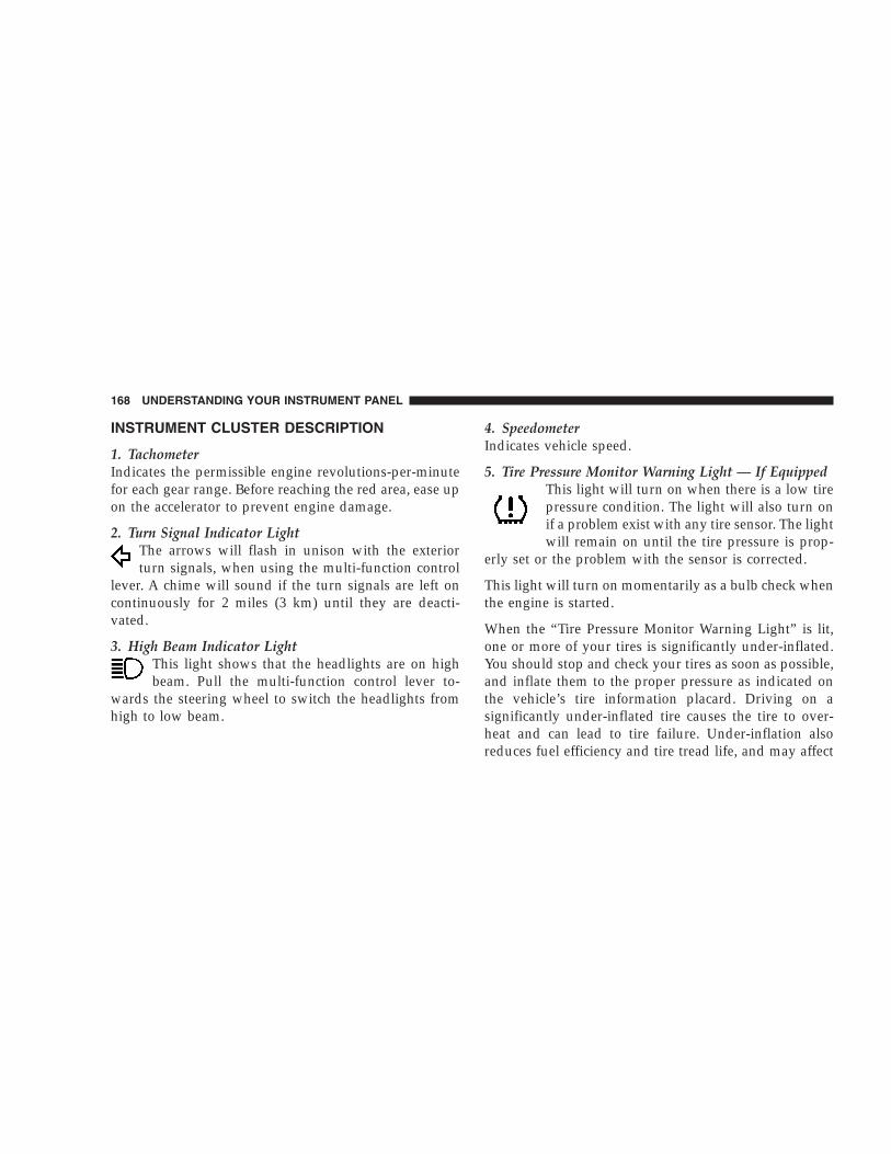
INSTRUMENT CLUSTER DESCRIPTION
1. TachometerIndicates the permissible engine revolutions-per-minutefor each gear range. Before reaching the red area, ease upon the accelerator to prevent engine damage.
2. Turn Signal Indicator LightThe arrows will flash in unison with the exteriorturn signals, when using the multi-function control
lever. A chime will sound if the turn signals are left oncontinuously for 2 miles (3 km) until they are deacti-vated.
3. High Beam Indicator LightThis light shows that the headlights are on highbeam. Pull the multi-function control lever to-
wards the steering wheel to switch the headlights fromhigh to low beam.
4. SpeedometerIndicates vehicle speed.
5. Tire Pressure Monitor Warning Light — If EquippedThis light will turn on when there is a low tirepressure condition. The light will also turn onif a problem exist with any tire sensor. The lightwill remain on until the tire pressure is prop-
erly set or the problem with the sensor is corrected.
This light will turn on momentarily as a bulb check whenthe engine is started.
When the “Tire Pressure Monitor Warning Light” is lit,one or more of your tires is significantly under-inflated.You should stop and check your tires as soon as possible,and inflate them to the proper pressure as indicated onthe vehicle’s tire information placard. Driving on asignificantly under-inflated tire causes the tire to over-heat and can lead to tire failure. Under-inflation alsoreduces fuel efficiency and tire tread life, and may affect
168 UNDERSTANDING YOUR INSTRUMENT PANEL

the vehicle’s handling and stopping ability. Each tire,including the spare, should be checked monthly whencold and set to the recommended inflation pressure asspecified on the vehicle placard. (See page 268 for moreinformation.)
6. 4LO Mode Indicator Light — If EquippedThis light alerts the driver that the vehicle is inthe 4 LO four–wheel drive mode. The front andrear driveshafts are mechanically locked to-gether forcing the front and rear wheels to
rotate at the same speed. (See page 236 for more infor-mation.)
7. Fog Light Indicator Light — If EquippedThis light shows when the front fog lights are on.
8. Malfunction Indicator LightThis light is part of an onboard diagnostic systemcalled OBD II which monitors engine and auto-matic transmission control systems. This light
will illuminate when the ignition is in the ON positionbefore engine start. If the bulb does not come on whenturning the ignition key from OFF to ON, have thecondition checked promptly.
Certain conditions such has a loose or missing gas cap,poor fuel quality, etc. may illuminate the light afterengine start. The vehicle should be serviced if the lightstays on through several typical driving cycles. In mostsituations, the vehicle will drive normally and will notrequire towing.
When the engine is running, the “Malfunction IndicatorLight” may flash to alert of serious conditions that couldlead to immediate loss of power or severe catalytic
UNDERSTANDING YOUR INSTRUMENT PANEL 169
4

converter damage. The vehicle should be serviced assoon as possible if this occurs. (See page 309 for moreinformation.)
9. Anti-Lock Warning Light (ABS) — If EquippedThis light monitors the Anti-Lock Brake System(ABS) described elsewhere in this manual. This
light will come on when the ignition switch is turned tothe ON position and may stay on for as long as threeseconds.
If the light comes back on immediately or comes onduring driving, it indicates that the Anti-Lock portion ofthe brake system is not functioning and that service isrequired, however, the conventional brake system willcontinue to operate normally provided that the BRAKEwarning light is not on. Also, a chime will sound if thelight comes back on.
If the ABS light is on, the brake system should be servicedas soon as possible to restore the benefit of Anti-LockBrakes.
The operation of the ABS light can be checked by turningthe ignition switch from the OFF position to the ONposition. The light should illuminate for approximatelytwo seconds. The light should then turn off unless theparking brake is applied or a brake fault is detected. If thelight does not illuminate, have the light inspected by anauthorized dealer.
10. Charging System Warning LightThis light shows the status of the electrical charg-ing system. The light should come on for three
seconds when the ignition is first turned ON. If the lightcomes back on immediately or comes on while driving, itmeans that there is a problem with the charging systemor the battery is low. Also, a chime will sound if the lightcomes back on. See your authorized dealer immediately.
170 UNDERSTANDING YOUR INSTRUMENT PANEL

11. Temperature GageIndicates engine coolant temperature. Any read-ing within the normal range indicates that thecooling system is operating satisfactorily.
The gage pointer will likely indicate a higher temperature(above center scale) when driving in hot weather, upmountain grades, in heavy stop and go traffic, or whentowing a trailer. It should not be allowed to exceed theupper limits of the normal operating range.
If the pointer rises to the red zone (five chimes willoccur), pull over and stop the vehicle. Do not turn theengine off. Idle the vehicle with the air conditioningturned off, until the pointer drops back into the normalrange. If the engine remains in the high range, turn theengine off and call for service.
12. Reset ButtonPress this button to toggle between the odometer and tripodometer display. When in the trip odometer mode,holding the button in resets the trip odometer. Also,pressing the “Reset” button will clear out any warningmessages in the odometer display.
13. Odometer/Trip OdometerA vacuum fluorescent display indicates the total distancethe vehicle has been driven. Also, the cluster will display,replacing the odometer/trip odometer, vehicle warningmessages such as: door/gate/glass ajar and low washerfluid. See appropriate sections for more information.
NOTE: If vehicle is equipped with the optional Elec-tronic Vehicle Information Center (EVIC) in the overheadconsole, all warnings including “door”, “GATE”,“GLASS”, and “LOWASH” will only be displayed in the
UNDERSTANDING YOUR INSTRUMENT PANEL 171
4

EVIC display (not in the instrument cluster). For addi-tional information, refer to “Overhead Console — IfEquipped” in Section 3.
U.S. federal regulations require that upon transfer ofvehicle ownership, the seller certify to the purchaser thecorrect mileage that the vehicle has been driven. There-fore, if the odometer reading is changed during repair orreplacement, be sure to keep a record of the readingbefore and after the service so that the correct mileage canbe determined.
14. Cruise Indicator LightThis indicator lights when the speed controlsystem is turned ON.
15. Oil Pressure Warning LightShows low engine oil pressure. The light will comeon and remain on when the ignition switch is
turned from the OFF to the ON position, and the light
will turn off after the engine is started. If the bulb doesnot come on, have the system checked by your autho-rized dealer.
If the warning light comes on and remains on whiledriving, stop the vehicle and shut off the engine. DONOT OPERATE THE VEHICLE UNTIL THE CAUSE ISCORRECTED. Also, a single chime will sound.
16. Transmission Temperature Warning LightThis light indicates that there is excessive trans-mission fluid temperature that might occur with
severe usage such as trailer towing or snow plowing. Ifthis light comes on, stop the vehicle and run the engine atidle or faster, with the transmission in N (Neutral) untilthe light goes off.
172 UNDERSTANDING YOUR INSTRUMENT PANEL

17. Part Time Indicator Light — If EquippedThis light alerts the driver that the vehicle is inthe PART TIME four–wheel drive high rangemode, and the front and rear driveshafts are
mechanically locked together forcing the front and rearwheels to rotate at the same speed. (See page 236 formore information.)
18. Brake Warning LightThis light monitors various brake functions,including brake fluid level and parking brakeapplication. If the light comes on, it may indi-cate that the parking brake is applied, or there
is a low brake fluid level. On vehicles equipped withAnti-Lock brakes (ABS), it may also indicate an ABSmalfunction that could lead to reduced braking perfor-mance.
WARNING!
Driving a vehicle with the BRAKE warning light onis dangerous. A significant decrease in braking per-formance or vehicle stability during braking mayoccur. It will take you longer to stop the vehicle orwill make your vehicle harder to control. You couldhave an accident. Have the vehicle checked immedi-ately.
The operation of the BRAKE warning light can bechecked by turning the ignition switch from the OFFposition to the ON position. The light should illuminatefor approximately two seconds. The light should thenturn off unless the parking brake is applied or a brakefault is detected. If the light does not illuminate, have thelight inspected by an authorized dealer.
UNDERSTANDING YOUR INSTRUMENT PANEL 173
4

Also, the light will come on when the parking brake isapplied with the ignition switch in the ON position.
NOTE: This light shows only that the parking brake isapplied. It does not show the degree of brake application.
If the parking brake is off and the light remains on, havethe brake system inspected as soon as possible.
19. Full Time Indicator Light — If EquippedThis light alerts the driver that the vehicle is inthe FULL TIME four–wheel drive mode, andemploys the inter-axle differential which al-lows the front and rear wheels to rotate at
different speeds. (See page 236 for more information.)
20. Sentry Key/Security Alarm Indicator Light — IfEquippedRefer to “Sentry Key Immobilizer System” or “VehicleSecurity Alarm” in Section 2 of this manual for moreinformation.
21. Fuel GageWhen the ignition key is in the ON position, the pointerwill show the level of fuel remaining in the fuel tank. Asmall arrow indicates the side of the vehicle where thefiller cap (gas cap) is located.
22. Low Fuel Warning LightWhen the fuel level reaches approximately 2.3 U.S.Gallons (8.7 Liters) this light will come on andremain on until fuel is added. The “Low Fuel
Warning Light” may turn on and off again, especiallyduring and after hard braking, accelerations, or turns.This occurs due to the shifting of the fuel in the tank.Also, a single chime will sound.
23. Airbag Warning LightThis indicator lights and remains lit for 6 to 8seconds when the ignition is first turned on. If the
light doesn’t come on, stays on, or comes on while driving,have the airbag system checked by an authorized dealer.
174 UNDERSTANDING YOUR INSTRUMENT PANEL
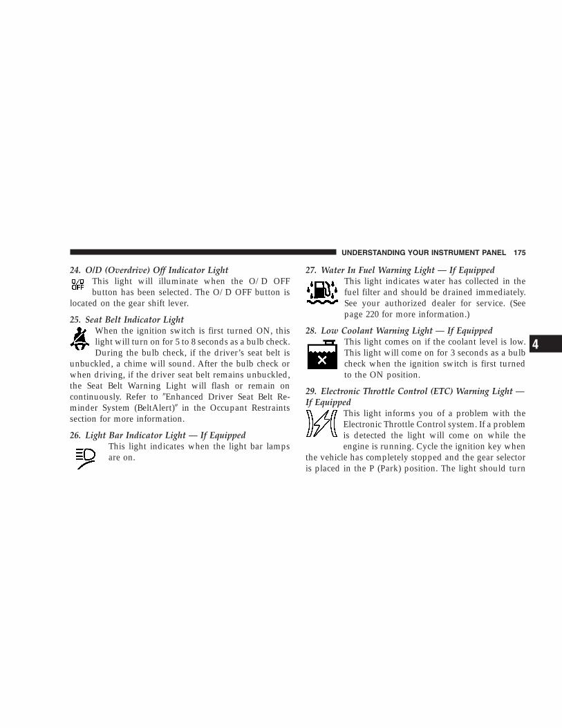
24. O/D (Overdrive) Off Indicator LightThis light will illuminate when the O/D OFFbutton has been selected. The O/D OFF button is
located on the gear shift lever.
25. Seat Belt Indicator LightWhen the ignition switch is first turned ON, thislight will turn on for 5 to 8 seconds as a bulb check.During the bulb check, if the driver’s seat belt is
unbuckled, a chime will sound. After the bulb check orwhen driving, if the driver seat belt remains unbuckled,the Seat Belt Warning Light will flash or remain oncontinuously. Refer to �Enhanced Driver Seat Belt Re-minder System (BeltAlert)� in the Occupant Restraintssection for more information.
26. Light Bar Indicator Light — If EquippedThis light indicates when the light bar lampsare on.
27. Water In Fuel Warning Light — If EquippedThis light indicates water has collected in thefuel filter and should be drained immediately.See your authorized dealer for service. (Seepage 220 for more information.)
28. Low Coolant Warning Light — If EquippedThis light comes on if the coolant level is low.This light will come on for 3 seconds as a bulbcheck when the ignition switch is first turnedto the ON position.
29. Electronic Throttle Control (ETC) Warning Light —If Equipped
This light informs you of a problem with theElectronic Throttle Control system. If a problemis detected the light will come on while theengine is running. Cycle the ignition key when
the vehicle has completely stopped and the gear selectoris placed in the P (Park) position. The light should turn
UNDERSTANDING YOUR INSTRUMENT PANEL 175
4

off. If the light remains lit with the engine running yourvehicle will usually be drivable, however, see your dealerfor service as soon as possible. If the light is flashingwhen the engine is running, immediate service is re-quired and you may experience reduced performance, anelevated/rough idle or engine stall and your vehicle mayrequire towing. The light will come on when the ignitionis first turned on and remain on briefly as a bulb check.If the light does not come on during starting, have thesystem checked by an authorized dealer.
30. Glow Plug Indicator Light — If EquippedThis light will illuminate when the ignitionswitch is first turned to the ON position. Waituntil the light turns off before starting thevehicle. Refer to “Starting Procedures” in Sec-
tion 5 of this manual. (See page 220 for moreinformation.)
ELECTRONIC DIGITAL CLOCK
The clock and radio each use the display panel built intothe radio. A digital readout shows the time in hours andminutes whenever the ignition switch is in the ON orACC position and the time button is pressed.
When the ignition switch is in the OFF position, or whenthe radio frequency is being displayed, time keeping isaccurately maintained.
Clock Setting Procedure
1. Turn the ignition switch to the ON or ACC positionand press the time button. Using the tip of a ballpoint penor similar object, press either the hour (H) or minute (M)buttons on the radio.
2. Press the H button to set hours or the M button to setminutes. The time setting will increase each time youpress a button.
176 UNDERSTANDING YOUR INSTRUMENT PANEL

RADIO GENERAL INFORMATION
Radio Broadcast SignalsYour new radio will provide excellent reception undermost operating conditions. Like any system, however, carradios have performance limitations, due to mobile op-eration and natural phenomena, which might lead you tobelieve your sound system is malfunctioning. To helpyou understand and save you concern about these “ap-parent” malfunctions, you must understand a point ortwo about the transmission and reception of radio sig-nals.
Two Types of SignalsThere are two basic types of radio signals... AM orAmplitude Modulation, in which the transmitted soundcauses the amplitude, or height, of the radio waves tovary... and FM or Frequency Modulation, in which thefrequency of the wave is varied to carry the sound.
Electrical DisturbancesRadio waves may pick up electrical disturbances duringtransmission. They mainly affect the wave amplitude,and thus remain a part of the AM reception. Theyinterfere very little with the frequency variations thatcarry the FM signal.
AM ReceptionAM sound is based on wave amplitude, so AM receptioncan be disrupted by such things as lightning, power linesand neon signs.
FM ReceptionBecause FM transmission is based on frequency varia-tions, interference that consists of amplitude variationscan be filtered out, leaving the reception relatively clear,which is the major feature of FM radio.
NOTE: On vehicles so equipped the radio, steeringwheel radio controls and 6 disc CD/DVD changer will
UNDERSTANDING YOUR INSTRUMENT PANEL 177
4

remain active for up to 45 seconds after the ignitionswitch has been turned off. Opening a vehicle front doorwill cancel this feature.
SALES CODE RAZ—AM/ FM STEREO RADIOWITH CASSETTE TAPE PLAYER, CD PLAYERAND CD CHANGER CONTROLS
NOTE: The radio sales code is located on the lower leftside of your radio faceplate.
Operating Instructions — Radio
NOTE: Power to operate the radio is controlled by theignition switch. It must be in the ON or ACC position tooperate the radio.
Power Switch, Volume ControlPress the ON/VOL control to turn the radio on. Turn thevolume control clockwise to increase the volume. Thevolume will be displayed and continuously updatedwhile the button is pressed.
Seek Button (Radio Mode)Press and release the Seek button to search for the nextstation in either the AM or FM mode. Press the top of thebutton to seek up and the bottom to seek down. Holdingthe button will by pass stations until you release thebutton.
RAZ Radio
178 UNDERSTANDING YOUR INSTRUMENT PANEL

TuningPress the TUNE control up or down to increase ordecrease the frequency. If you press and hold the button,the radio will continue to tune until you release thebutton. The frequency will be displayed and continu-ously updated while the button is pressed.
Radio Data System (RDS)
The Radio Data System allows radio broadcasting sta-tions to send data signals on a subcarrier frequencywhich is added to the stereo signal. RDS was developedto give FM receivers user-friendly features, such asProgram Service name (PS) and Program Type (PTY).Program Service name is typically used by the broad-caster to display the station’s name or call letters, forexample �WNIC�. Typically these are 8 characters inlength and are displayed by the radio for those stations
which are broadcasting this information. PTY (ProgramType) is used to characterize the station’s program ma-terial, for example �Rock Music�.
PTY (Program Type) ButtonPressing this button once will turn on the PTY mode for5 seconds. If no action is taken during the 5 second timeout the PTY icon will turn off. Pressing the PTY buttonwithin 5 seconds will allow the program format type tobe selected. Many radio stations do not currently broad-cast PTY information.
Toggle the PTY button to select the following formattypes:
Program Type Radio DisplayAdult Hits Adlt HitClassical ClassiclClassic Rock Cls RockCollege College
UNDERSTANDING YOUR INSTRUMENT PANEL 179
4

Program Type Radio DisplayCountry CountryInformation InformJazz JazzForeign Language LanguageNews NewsNostalgia NostalgaOldies OldiesPersonality PersnltyPublic PublicRhythm and Blues R & BReligious Music Rel MuscReligious Talk Rel TalkRock RockSoft SoftSoft Rock Soft RckSoft Rhythm and Blues Soft R&B
Program Type Radio DisplaySports SportsTalk TalkTop 40 Top 40Weather Weather
By pressing the SEEK button when the PTY icon isdisplayed, the radio will be tuned to the next frequencystation with the same selected PTY name. The PTYfunction only operates when in the FM mode.
The radio display will flash “SEEK” and the selected PTYprogram type when searching for the next PTY station. Ifno station is found with the selected PTY program type,the radio will return to the last preset station.
If a preset button is activated while in the PTY (ProgramType) mode, the PTY mode will be exited and the radiowill tune to the preset station.
180 UNDERSTANDING YOUR INSTRUMENT PANEL

Pressing PTY, then SCAN will scan the FM Band and stopat all RDS stations. Each RDS station will be played for a5 second scan once around the FM Band and stop at thelast station. The PTY icon will then turn off.
BalanceThe Balance control adjusts the left-to-right speaker bal-ance. Push in the button and it will pop out. Adjust thebalance and push the button back in. The balance will bedisplayed and continuously updated while the button isturned.
FadeThe Fade control provides for balance between the frontand rear speakers. Push in the button and it will pop out.Adjust the balance and push the button back in. The fadewill be displayed and continuously updated while thebutton is turned.
Tone ControlSlide the Bass and/or Treble controls up or down toadjust the sound for the desired tone. The treble, and basswill be displayed and continuously updated while theslide is moved.
AM/FM SelectionPress the AM/FM button to change from AM to FM. Theoperating mode will be displayed next to the stationfrequency. The display will show ST when a stereostation is received.
Scan ButtonPressing the SCAN button causes the tuner to search forthe next station, in either AM or FM, pausing for 5 secondsat each listenable station before continuing to the next.
Pressing the AM/FM button continues the search in thealternate frequency band.
To stop the search, press SCAN a second time.
UNDERSTANDING YOUR INSTRUMENT PANEL 181
4

To Set The Radio Push-button MemoryWhen you are receiving a station that you wish tocommit to push-button memory, press the SET button.SET 1 will show in the display window. Select thepush-button you wish to lock onto this station and pressand release that button. If a station is not selected within5 seconds after pressing the SET button, the station willcontinue to play but will not be locked into push-buttonmemory.
You may add a second station to each push-button byrepeating the above procedure with this exception: Pressthe SET button twice and SET 2 will show in the displaywindow. Each button can be set for SET 1 and SET 2 inboth AM and FM. This allows a total of 10 AM and 10 FMstations to be locked into memory. You can recall thestations stored in SET 2 memory by pressing the push-button twice.
To Change From Clock To Radio ModePress the Time button to change the display betweenradio frequency and time.
Operating Instructions — Tape PlayerInsert the cassette with the exposed tape side toward theright and the mechanical action of the player will gentlypull the cassette into the play position.
NOTE: When subjected to extremely cold temperatures,the tape mechanism may require a few minutes to warmup for proper operation. Sometimes poor playback maybe experienced due to a defective cassette tape. Clean anddemagnetize the tape heads at least twice a year.
Seek ButtonPress the SEEK button up for the next selection on thetape and down to return to the beginning of the currentselection.
182 UNDERSTANDING YOUR INSTRUMENT PANEL

Press the SEEK button up or down to move the tracknumber to skip forward or backward 1 to 6 selections.Press the SEEK button once to move 1 selection, twice tomove 2 selections, etc.
Fast Forward (FF)Press the FF button up momentarily to advance the tapein the direction that it is playing. The tape will advanceuntil the button is pressed again or the end of the tape isreached. At the end of the tape, the tape will play in theopposite direction.
Rewind (RW)Press the RW button momentarily to reverse the tapedirection. The tape will reverse until the button is pressedagain or until the end of the tape is reached. At the end ofthe tape, the tape will play in the opposite direction.
Tape EjectPress the EJT Tape button and the cassette will disengageand eject from the radio.
Scan ButtonPress this button to play 10 seconds of each selection.Press the scan button a second time to cancel the feature.
Changing Tape DirectionIf you wish to change the direction of tape travel (sidebeing played), press the PTY button. The lighted arrow inthe display window will show the new direction.
Metal Tape SelectionIf a standard metal tape is inserted into the player, theplayer will automatically select the correct equalizationand the 70 symbol will appear in the display window.
UNDERSTANDING YOUR INSTRUMENT PANEL 183
4

Pinch Roller ReleaseIf ignition power or the radio ON/OFF switch are turnedoff, the pinch roller will automatically retract to protectthe tape from any damage. When power is restored to thetape player, the pinch roller will automatically reengageand the tape will resume play.
Noise ReductionThe Dolby Noise Reduction System* is on whenever thetape player is on, but may be switched off.
To turn off the Dolby Noise reduction System: Press theDolby button (button 2) after you insert the tape. The NRlight in the display will go off when the Dolby System isoff. The Dolby System is automatically reactivated eachtime a tape is inserted.
* ”Dolby” noise reduction manufactured under licensefrom Dolby Laboratories Licensing Corporation. Dolbyand the double-D symbol are trademarks of Dolby Labo-ratories Licensing Corporation.
Operating Instructions — CD Player
NOTE: The ignition switch must be in the ON or ACCposition and the volume control ON before the CD playerwill operate.
CAUTION!
This CD player will accept 4 3⁄4 inch (12 cm) discsonly. The use of other sized discs may damage theCD player mechanism.
Inserting The Compact DiscThe CD player contained within the radio is not amulti-disc changer, and will only accept one CD. Gentlyinsert one CD into the CD player with the CD label facingup. The CD will automatically be pulled into the CDPlayer.
184 UNDERSTANDING YOUR INSTRUMENT PANEL

If the volume control is ON, the unit will switch fromradio to CD mode and begin to play. The display willshow the track number and index time in minutes andseconds. Play will begin at the start of track one.
NOTE:• You may eject a disc with the radio OFF. The ignition
switch must be in the ON or ACC position to insert adisc with the radio OFF.
• If you insert a disc with the ignition ON and the radioOFF, the CD will automatically be pulled into the CDPlayer and the display will show the time of day. Ifyou insert a disc with the ignition OFF, the display willshow the time of day for about 5 seconds, then go out.
Seek ButtonPress the top of the SEEK button for the next selection onthe CD. Press the bottom of the button to return to thebeginning of the current selection, or return to thebeginning of the previous selection if the CD is within thefirst 10 seconds of the current selection.
EJT CD (Eject) ButtonPress this button and the disc will unload and move tothe entrance for easy removal. The unit will switch to theradio mode.
If you do not remove the disc within 15 seconds, it will bereloaded. The radio mode will continue to appear.
The disc can be ejected with the radio OFF.
UNDERSTANDING YOUR INSTRUMENT PANEL 185
4

FF/TUNE/RWPress FF (Fast Forward) and the CD player will begin tofast forward until FF is released. The RW ( Reverse)button works in a similar manner.
Program Button 4 (Random Play)Press this button while the CD is playing to activateRandom Play. This feature plays the tracks on the se-lected disc in random order to provide an interestingchange of pace.
Press the SEEK button to move to the next randomlyselected track.
Press TUNE FF to fast forward through the tracks. Pressthe FF button a second time to stop the fast forwardfeature. If TUNE RW is pressed, the current track willreverse to the beginning of the track and begin playing.
Press button 4 a second time to stop Random Play.
MODEPress the MODE button to select between the tape player,CD player, or satellite radio (if equipped).
To select Satellite Radio (if equipped), press the MODEbutton until the word SIRIUS appears. The following willbe displayed in this order: After three seconds, thecurrent channel name and number will be displayed forfive seconds. The current program type and channelnumber will then be displayed for five seconds. Thecurrent channel name and number will then be displayeduntil an action occurs. A CD or tape may remain in theplayer while in the Satellite Radio mode.
Tape CD ButtonPress this button to select between CD player and Tapeplayer.
186 UNDERSTANDING YOUR INSTRUMENT PANEL

Time ButtonPress this button to change the display from elapsed CDplaying time to time of day.
Scan ButtonPress this button to play the first 10 seconds of each track.To stop the scan function, press the button a second time.
CD Changer Control Capability — If EquippedThis radio is compatible with a remote mounted CDchanger available through Mopar Accessories. The fol-lowing instructions are for the radio controls that operatethis CD changer.
Mode ButtonTo activate the CD changer, press the MODE button untilCD information appears on the display.
Disc Up/Program Button 1Press the DISC up (button 1) button to play the nextavailable disc.
Disc Down/Program Button 5Press the DISC down (button 5) button to play theprevious disc.
Seek ButtonPress the SEEK up or down to select another track on thesame disc. A SEEK symbol will appear on the display.
Fast Forward And Rewind ButtonsPress and hold the FF button for fast forward. Press andhold the RW button for fast reverse.
The audio output can be heard when fast forward andfast reverse are activated.
UNDERSTANDING YOUR INSTRUMENT PANEL 187
4

Random Play (RND)Press the Random button to play the tracks on theselected disc in random order for an interesting change ofpace.
Random can be cancelled by pressing the button a secondtime or by ejecting the CD from the changer.
CD Diagnostic IndicatorsWhen driving over a very rough road, the CD player mayskip momentarily. Skipping will not damage the disc orthe player, and play will resume automatically.
As a safeguard and to protect your CD player, one of thefollowing warning symbols may appear on your display.
A CD HOT symbol indicates the player is too hot.
CD HOT will pause the operation. Play can be resumedwhen the operating temperature is corrected or anotherMODE is selected.
An ERR symbol will appear on the display if the laser isunable to read the Disc data for the following reasons:
• Excessive vibration
• Disc inserted upside down
• Damaged disc
• Water condensation on optics
188 UNDERSTANDING YOUR INSTRUMENT PANEL

SALES CODE RBK—AM/ FM STEREO RADIOWITH CD PLAYER AND CD CHANGERCONTROLS
NOTE: The radio sales code is located on the lower leftside of your radio faceplate.
Radio Operation
Power/Volume ControlPress the ON/VOL control to turn the radio on. Turn thevolume control clockwise to increase the volume.
NOTE: Power to operate the radio is supplied throughthe ignition switch. It must be in the ON or ACC positionto operate the radio.
SeekPress and release the SEEK button to search for the nextstation in either the AM or FM mode. Press the top of thebutton to seek up or the bottom to seek down. The radiowill remain tuned to the new station until you makeanother selection. Holding the button in will bypassstations without stopping until you release it.
RBK Radio
UNDERSTANDING YOUR INSTRUMENT PANEL 189
4

TunePress the TUNE control up or down to increase ordecrease the frequency. If you press and hold the button,the radio will continue to tune until you release thebutton. The frequency will be displayed and continu-ously updated while the button is pressed.
To Set The Radio Push-Button MemoryWhen you are receiving a station that you wish tocommit to push-button memory, press the SET button.SET 1 will show in the display window. Select the “1–5”button you wish to lock onto this station and press andrelease that button. If a button is not selected within 5seconds after pressing the SET button, the station willcontinue to play but will not be locked into push-buttonmemory.
You may add a second station to each push-button byrepeating the above procedure with this exception: Pressthe SET button twice and SET 2 will show in the display
window. Each button can be set for SET 1 and SET 2 inboth AM and FM. This allows a total of 10 AM and 10 FMstations to be locked into push-button memory. Thestations stored in SET 2 memory can be selected bypressing the push-button twice. Every time a presetbutton is used a corresponding button number will bedisplayed.
AudioThe audio button controls the BASS, TREBLE, BAL-ANCE, and FADE.
Press the AUDIO button and BASS will be displayed.Press the SEEK + or SEEK – to increase or decrease theBass tones.
Press the AUDIO button a second time and TREB will bedisplayed. Press the SEEK + or SEEK – to increase ordecrease the Treble tones.
190 UNDERSTANDING YOUR INSTRUMENT PANEL

Press the AUDIO button a third time and BAL will bedisplayed. Press the SEEK + or SEEK – to adjust thesound level from the right or left side speakers.
Press the AUDIO button a fourth time and FADE will bedisplayed. Press the SEEK + or SEEK – to adjust thesound level between the front and rear speakers.
Press the AUDIO button again or wait 5 seconds to exitsetting tone, balance, and fade.
AM/FM SelectionPress the AM/FM button to change from AM to FM. Theoperating mode will be displayed next to the stationfrequency. The display will show ST when a stereostation is received.
TimePress the TIME button to change the display betweenradio frequency and time.
General InformationThis radio complies with Part 15 of FCC rules and withRSS-210 of Industry Canada. Operation is subject to thefollowing conditions:
1. This device may not cause harmful interference,
2. This device must accept any interference received,including interference that may cause undesired opera-tion.
NOTE: Changes or modifications not expressively ap-proved by the party responsible for compliance couldvoid the user’s authority to operate the equipment.
CD Player Operation
NOTE: The ignition switch must be in the ON or ACCposition and the volume control ON before the CD playerwill operate.
UNDERSTANDING YOUR INSTRUMENT PANEL 191
4

Inserting The Compact Disc
CAUTION!
This CD player will accept 4 3⁄4 inch (12 cm) discsonly. The use of other sized discs may damage theCD player mechanism.
You may either insert or eject a disc with the radio OFF.
If you insert a disc with the ignition ON and the radioOFF, the display will show the time of day.
If the power is ON, the unit will switch from radio to CDmode and begin to play when you insert the disc. Thedisplay will show the track number and index time inminutes and seconds. Play will begin at the start of trackone.
SeekPress the top of the SEEK button for the next selection onthe CD. Press the bottom of the button to return to thebeginning of the current selection, or return to thebeginning of the previous selection if the CD is within thefirst second of the current selection.
EJT — EjectPress the EJT button and the disc will unload and moveto the entrance for easy removal. The unit will switch tothe radio mode.
If you do not remove the disc within 15 seconds, it will bereloaded. The unit will continue in radio mode.
The disc can be ejected with the radio and ignition OFF(except on convertibles).
192 UNDERSTANDING YOUR INSTRUMENT PANEL

FF/TUNE/RWPress FF (Fast Forward) and the CD player will begin tofast forward until FF is released. The RW ( Reverse)button works in a similar manner.
Random Play — RND/Program Button 4Press the RND (button 4) button while the CD is playingto activate Random Play. This feature plays the tracks onthe selected disc in random order to provide an interest-ing change of pace.
Press the SEEK button to move to the next randomlyselected track.
Press the RND (button 4) button a second time to stopRandom Play.
ModePress the MODE button repeatedly to select between theCD player, the optional remote CD changer and the
Satellite Radio (if equipped). When Satellite Radio (ifequipped) is selected “SAT” will appear in your radiodisplay.
A CD or tape may remain in the player while in theSatellite mode.
TimePress the TIME button to change the display fromelapsed CD playing time to time of day.
CD Changer Control Capability — If EquippedThis radio is compatible with a remote mounted CDchanger available through Mopar Accessories. The fol-lowing instructions are for the radio controls that operatethis CD changer.
Mode ButtonTo activate the CD changer, press the MODE button untilCD information appears on the display.
UNDERSTANDING YOUR INSTRUMENT PANEL 193
4

Disc Up/Program Button 1Press the DISC up (button 1) button to play the nextavailable disc.
Disc Down/Program Button 5Press the DISC down (button 5) button to play theprevious disc.
Seek ButtonPress the SEEK up or down to select another track on thesame disc. A SEEK symbol will appear on the display.
Fast Forward And Rewind ButtonsPress and hold the FF button for fast forward. Press andhold the RW button for fast reverse.
The audio output can be heard when fast forward andfast reverse are activated.
Random Play (RND)Press the Random button to play the tracks on theselected disc in random order for an interesting change ofpace.
Random can be cancelled by pressing the button a secondtime or by ejecting the CD from the changer.
Operating Instructions - Satellite Radio Mode (IfEquipped)Refer to the Satellite Radio section of the Owner’sManual.
CD Diagnostic IndicatorsWhen driving over a very rough road, the CD player mayskip momentarily. Skipping will not damage the disc orthe player, and play will resume automatically.
As a safeguard and to protect your CD player, one of thefollowing warning symbols may appear on your display.
A CD HOT symbol indicates the player is too hot.
194 UNDERSTANDING YOUR INSTRUMENT PANEL

CD HOT will pause the operation. Play can be resumedwhen the operating temperature is corrected or anotherMODE is selected.
An ERR symbol will appear on the display if the laser isunable to read the Disc data for the following reasons:
• Excessive vibration
• Disc inserted upside down
• Damaged disc
• Water condensation on optics
SALES CODE RBQ—AM/FM STEREO RADIOWITH 6 - DISC CD CHANGER
NOTE: The radio sales code is located on the lower leftside of your radio faceplate.
Radio Operation
Power/Volume ControlPress the PWR/VOL control to turn the radio on. Turnthe volume control clockwise to increase the volume.
RBQ Radio
UNDERSTANDING YOUR INSTRUMENT PANEL 195
4

NOTE: Power to operate the radio is controlled by theignition switch. It must be in the ON or ACC position tooperate the radio.
ModePress the MODE button repeatedly to select between AM,FM, the CD changer and Sirius Satellite Radio™ (ifequipped). The display will show ST when a stereostation is received.
To select Sirius Satellite Radio™ (if equipped), press theMODE button until the word SIRIUS appears. The fol-lowing will be displayed in this order: After three sec-onds, the current channel name and number will bedisplayed for five seconds. The current program type andchannel number will then be displayed for five seconds.The current channel name and number will then bedisplayed until an action occurs. CD’s may remain in theplayer while in the Satellite Radio mode.
SeekPress and release the SEEK button to search for the nextstation in either the AM or FM mode. Press the top of thebutton to seek up and the bottom to seek down. Theradio will remain tuned to the new station until youmake another selection. Holding the button in will by-pass stations without stopping until you release it.
TunePress the TUNE control up or down to increase ordecrease the frequency. If the button is pressed and held,the radio will continue to tune until the button isreleased. The frequency will be displayed and continu-ously updated while the button is pressed.
To Set The Radio Push-Button MemoryWhen you are receiving a station that you wish tocommit to push-button memory, press the SET RNDbutton. SET 1 will show in the display window. Select the“1–6” button you wish to lock onto this station and press
196 UNDERSTANDING YOUR INSTRUMENT PANEL

and release that button. If a button is not selected within5 seconds after pressing the SET RND button, the stationwill continue to play but will not be locked into push-button memory.
You may add a second station to each push-button byrepeating the above procedure with this exception: Pressthe SET button twice and SET 2 will show in the displaywindow. Each button can be set for SET 1 and SET 2 inboth AM and FM. This allows a total of 12 AM and 12 FMstations to be locked into push-button memory. Thestations stored in SET 2 memory can be selected bypressing the corresponding push-button twice. Everytime a preset button is used, a corresponding buttonnumber will be displayed.
AudioThe audio button controls the BASS, TREBLE, BAL-ANCE, and FADE.
Press the AUDIO button and BASS will be displayed.Press the SEEK + or SEEK – to increase or decrease theBass tones.
Press the AUDIO button a second time and TREB will bedisplayed. Press the SEEK + or SEEK – to increase ordecrease the Treble tones.
Press the AUDIO button a third time and BAL will bedisplayed. Press the SEEK + or SEEK – to adjust thesound level from the right or left side speakers.
Press the AUDIO button a fourth time and FADE will bedisplayed. Press the SEEK + or SEEK – to adjust thesound level between the front and rear speakers.
Press the AUDIO button again or wait 5 seconds to exitsetting tone, balance, and fade.
Time ButtonPress the TIME button to change the display betweenradio frequency and time.
UNDERSTANDING YOUR INSTRUMENT PANEL 197
4

General InformationThis radio complies with Part 15 of FCC rules and withRSS-210 of Industry Canada. Operation is subject to thefollowing conditions:
1. This device may not cause harmful interference,
2. This device must accept any interference received,including interference that may cause undesired opera-tion.
NOTE: Changes or modifications not expressively ap-proved by the party responsible for compliance couldvoid the user’s authority to operate the equipment.
CD Player Operation
NOTE: The ignition switch must be in the ON or ACCposition and the Power / Volume control pushed ONbefore the CD player will operate.
Inserting The Compact Disc
CAUTION!
This CD player will accept 4 3⁄4 inch (12 cm) discsonly. The use of other sized discs may damage theCD player mechanism.
You may either insert or eject a disc with the radio OFF.
If you insert a disc with the ignition ON and the radioOFF, the display will show the time of day. If you inserta disc with the ignition OFF, the display will show thetime of day for about 5 seconds, then go out.
If you insert a disc with the ignition ON and the radioON, the unit will switch from radio to CD mode andbegin to play when you insert the disc. The display will
198 UNDERSTANDING YOUR INSTRUMENT PANEL

show the disc number, the track number, and index timein minutes and seconds. Play will begin at the start oftrack 1.
LOAD/ EJT — LoadPress the LOAD/ EJT button and the button with thecorresponding number where the CD is being loaded.After the radio displays “load” insert the CD into theplayer.
Radio display will show “loading” when it is beingloaded.
LOAD / EJT — EjectPress the LOAD/ EJT button and the button with thecorresponding number where the CD was loaded and thedisc will unload and move to the entrance for easyremoval.
Radio display will show “ejecting” when it is beingejected.
If you have ejected a disc and have not removed it within15 seconds, it will be reloaded. If the CD is not removed,the radio will continue to play the non-removed CD. Ifthe CD is removed and there are other CD’s in the radio,the radio will play the next CD. If the CD is removed andthere are no other CD’s in the radio, the radio will returnto the last selected AM or FM mode.
The disc can be ejected with the radio and ignition OFF.
SeekPress the top of the SEEK button for the next selection onthe CD. Press the bottom of the button to return to thebeginning of the current selection, or return to thebeginning of the previous selection if the CD is within thefirst second of the current selection.
ScanPress the Scan button to scan through each track on theCD currently playing.
UNDERSTANDING YOUR INSTRUMENT PANEL 199
4

FF/TUNE/RWPress FF (Fast Forward) and the CD player will begin tofast forward until FF is released. The RW ( Reverse)button works in a similar manner.
Random Play — SET / RNDPress the RND button while the CD is playing to activateRandom Play. This feature plays the tracks on the disc inrandom order to provide an interesting change of pace.
Press the SEEK button to move to the next randomlyselected track.
Press the SET / RND button a second time to stopRandom Play.
PTY (Program Type) ButtonPressing this button once will turn on the PTY mode for5 seconds. If no action is taken during the 5 second timeout the PTY icon will turn off. Pressing the PTY button
repeatedly within 5 seconds will allow the programformat type to be selected. Many radio stations do notcurrently broadcast PTY information.
Toggle the PTY button to select the following formattypes:
Program Type Radio DisplayAdult Hits Adlt HitClassical ClassiclClassic Rock Cls RockCollege CollegeCountry CountryEmergency ALERT!Emergency Test TestInformation InformJazz JazzForeign Language LanguageNews News
200 UNDERSTANDING YOUR INSTRUMENT PANEL

Program Type Radio DisplayNostalgia NostalgaOldies OldiesPersonality PersnltyPublic PublicRhythm and Blues R & BReligious Music Rel MuscReligious Talk Rel TalkRock RockSoft SoftSoft Rock Soft RckSoft Rhythm and Blues Soft R&BSports SportsTalk TalkTop 40 Top 40Weather Weather
By pressing the SEEK button when the PTY icon isdisplayed, the radio will be tuned to the next frequencystation with the same selected PTY name. The PTYfunction only operates when in the FM mode.
The radio display will flash “SEEK” and the selected PTYprogram type when searching for the next PTY station. Ifno station is found with the selected PTY program type,the radio will return to the last station.
If a preset button is activated while in the PTY (ProgramType) mode, the PTY mode will be exited and the radiowill tune to the preset station.
By pressing the SCAN button when the PTY icon isdisplayed, the radio will stop at every PTY station on theband and list each corresponding program type in theradio display.
UNDERSTANDING YOUR INSTRUMENT PANEL 201
4

TimePress the TIME button to change the display fromelapsed CD playing time to time of day.
Operating Instructions - Satellite Radio Mode (IfEquipped)Refer to the Satellite Radio section of the Owner’sManual.
CD Diagnostic IndicatorsWhen driving over a very rough road, the CD player mayskip momentarily. Skipping will not damage the disc orthe player, and play will resume automatically.
As a safeguard and to protect your CD player, one of thefollowing warning symbols may appear on your display.
A CD HOT symbol indicates the player is too hot.
CD HOT will pause the operation. Play can be resumedwhen the operating temperature is corrected or anotherMODE is selected.
CD ERROR will appear on the display if the laser isunable to read the Disc data for the following reasons:
• Warped disc
• Excessive vibration
• Disc inserted upside down
• Damaged disc
• Water condensation on optics
202 UNDERSTANDING YOUR INSTRUMENT PANEL

SALES CODE RB1—AM/FM STEREO RADIOWITH DVD/GPS NAVIGATION SYSTEM
The navigation system provides maps, turn identifica-tion, selection menus and instructions for selecting a
variety of destinations and routes. Refer to your “Navi-gation User’s Manual” for detailed operating instruc-tions.
NOTE: If your vehicle is not equipped with the CDChanger option, you will not be able to use the Naviga-tion system and the CD Player simultaneously. Alwaysremove the Navigation DVD before inserting anotherdisc.
SATELLITE RADIO — IF EQUIPPEDSatellite radio uses direct satellite to receiver broadcast-ing technology to provide clear digital sound, coast tocoast. The subscription service provider is Sirius™ Satel-lite Radio. This service offers up to 100 channels of music,sports, news, entertainment, and programming for chil-dren, directly from its satellites and broadcasting studios.
RB1 Radio
UNDERSTANDING YOUR INSTRUMENT PANEL 203
4

System ActivationTo activate your Sirius Satellite Radio service, call thetoll-free number 888-539-7474, or visit the Sirius web siteat www.sirius.com. Please have the following informa-tion available when activating your system:
1. The Electronic Serial Number/Sirius IdentificationNumber (ESN/SID).
2. Credit card information.
3. Your Vehicle Identification Number.
Electronic Serial Number/Sirius IdentificationNumber (ENS/SID)The Electronic Serial Number/Sirius Identification Num-ber is needed to activate your Sirius Satellite Radiosystem. To access the ESN/SID, refer to the followingsteps:
ESN/SID Access With RBB, RAH and RBK RadiosWith the ignition switch in the ACCESSORY position andthe radio OFF, press the Tape Eject or CD Eject (depend-ing on the radio type) and Time buttons simultaneouslyfor 3 seconds. The first four digits of the twelve-digitESN/SID number will be displayed. Press the SEEK UPbutton to display the next four digits. Continue to pressthe SEEK UP button until all twelve ESN/SID digits havebeen displayed. The SEEK DOWN will page down untilthe first four digits are displayed. The radio will exit theESN/SID mode when any other button is pushed, theignition is turned OFF, or 5 minutes has passed since anybutton was pushed.
204 UNDERSTANDING YOUR INSTRUMENT PANEL

ESN/SID Access With RBP, RBU, RAZ, RB1 andRBQ RadiosWith the ignition switch in the ACCESSORY position andthe radio OFF, press the CD Eject and TIME buttonssimultaneously for 3 seconds. All twelve ESN/SID num-bers will be displayed. The radio will exit the ESN/SIDmode when any other button is pushed, the ignition isturned OFF, or 5 minutes has passed since any buttonwas pushed.
Selecting Satellite Mode in RBB, RAH and RBKRadiosPress the MODE button repeatedly until �S A� appears inthe display. A CD or tape may remain in the radio whilein the Satellite radio mode.
Selecting Satellite Mode in RBP, RBU, RAZ, RB1and RBQ RadiosPress the MODE button repeatedly until the word�SIRIUS� appears in the display. These radios will alsodisplay the following:
• After 3 seconds, the current channel name and channelnumber will be displayed for 5 seconds.
• The current program type and channel number willthen be displayed for 5 seconds.
• The current channel number will then be displayeduntil an action occurs.
A CD or tape may remain in the radio while in theSatellite radio mode.
UNDERSTANDING YOUR INSTRUMENT PANEL 205
4

Selecting a ChannelPress and release the SEEK or TUNE buttons to search forthe next channel. Press the top of the button to search upand the bottom of the button to search down. Holding theTUNE button causes the radio to bypass channels untilthe button is released.
Press and release the SCAN button (if equipped) toautomatically change channels every 7 seconds. Theradio will pause on each channel for 7 seconds beforemoving on to the next channel. The word �SCAN� willappear in the display between each channel change. Pressthe SCAN button a second time to stop the search.
NOTE: Channels that may contain objectionable contentcan be blocked. Contact Sirius Customer Care at 888-539-7474 to discuss options for channel blocking or unblock-ing. Please have your ESN/SID information available.
Storing and Selecting Pre-Set ChannelsIn addition to the 10 AM and 10 FM pre-set stations, youmay also commit 10 satellite stations to push buttonmemory. These satellite channel pre-set stations will noterase any AM or FM pre-set memory stations. Follow thememory pre-set procedures that apply to your radio.
Using the PTY (Program Type) Button (ifequipped)Follow the PTY button instructions that apply to yourradio.
PTY Button �SCAN�When the desired program type is obtained, press the�SCAN� button within five seconds. The radio will play 7seconds of the selected channel before moving to the nextchannel of the selected program type. Press the �SCAN�button a second time to stop the search.
206 UNDERSTANDING YOUR INSTRUMENT PANEL
NOTE: Pressing the �SEEK� or �SCAN� button whileperforming a music type scan will change the channel byone and stop the search. Pressing a pre-set memorybutton during a music type scan, will call up the memorychannel and stop the search.
PTY Button �SEEK�When the desired program is obtained, press the �SEEK�button within five seconds. The channel will change tothe next channel that matches the program type selected.
Satellite AntennaTo ensure optimum reception, do not place items on theroof around the rooftop antenna location. Metal objectsplaced within the line of sight of the antenna will causedecreased performance. Larger luggage items should beplaced as far forward as possible. Do not place itemsdirectly on or above the antenna.
Reception QualitySatellite reception may be interrupted due to one of thefollowing reasons.
• The vehicle is parked in an underground parkingstructure or under a physical obstacle.
• Dense tree coverage may interrupt reception in theform of short audio mutes.
• Driving under wide bridges or along tall buildings cancause intermittent reception.
• Placing objects over or too close to the antenna cancause signal blockage.
UNDERSTANDING YOUR INSTRUMENT PANEL 207
4

REMOTE SOUND SYSTEM CONTROLS — IFEQUIPPEDThe remote sound system controls are located on the rearsurface of the steering wheel. Reach behind the wheel toaccess the switches.
The right hand control is a rocker type switch with apush-button in the center and controls the volume andmode of the sound system. Pressing the top of the rockerswitch will increase the volume and pressing the bottomof the rocker switch will decrease the volume.
Pressing the center button will make the radio switchbetween the various modes available (AM/FM/TAPE/CD, Etc.).
The left hand control is a rocker type switch with apush-button in the center. The function of the left handcontrol is different depending on which mode you are in.
The following describes the left hand control operation ineach mode.
208 UNDERSTANDING YOUR INSTRUMENT PANEL
Radio OperationPressing the top of the switch will “Seek” up for the nextlistenable station and pressing the bottom of the switchwill “Seek” down for the next listenable station.
The button located in the center of the left hand controlwill tune to the next preset station that you have pro-grammed in the radio preset push-button.
Tape PlayerPressing the top of the switch once will go to the nextselection on the cassette. Pressing the bottom of theswitch once will go to the beginning of the currentselection or to the beginning of the previous selection if itis within the first 5 seconds of the current selection.
If you press the switch up or down twice it plays thesecond selection, three times, it will play the third, etc.
The button in the center of the left hand switch switchesthe side of the tape to be played.
CD Player — Single Disc in RadioPressing the top of the switch once will go to the nexttrack on the CD. Pressing the bottom of the switch oncewill go to the beginning of the current track or to thebeginning of the previous track if it is within one secondafter the current track begins to play.
If you press the switch up or down twice it plays thesecond track, three times, it will play the third, etc.
The button in the center of the left hand switch has nofunction in this mode.
CD Player — 6 Disc in Cargo AreaPressing the top of the switch once will go to the nexttrack on the CD. Pressing the bottom of the switch oncewill go to the beginning of the current track or to thebeginning of the previous track if it is within one secondafter the current track begins to play.
UNDERSTANDING YOUR INSTRUMENT PANEL 209
4

If you press the switch up or down twice it plays thesecond track, three times, it will play the third, etc.
The button in the center of the left hand switch will causethe CD changer to play the next available disc in the6–disc magazine.
CASSETTE TAPE AND PLAYER MAINTENANCETo keep the cassette tapes and player in good condition,take the following precautions:
1. Do not use cassette tapes longer than C-90; otherwise,sound quality and tape durability will be greatly dimin-ished.
2. Keep the cassette tape in its case to protect fromslackness and dust when it is not in use.
3. Keep the cassette tape away from direct sunlight, heatand magnetic fields such as the radio speakers.
4. Before inserting a tape, make sure that the label isadhering flat to the cassette.
5. A loose tape should be corrected before use. To rewinda loose tape, insert the eraser end of a pencil into the tapedrive gear and twist the pencil in the required directions.
Maintain your cassette tape player. The head and capstanshaft in the cassette player can pick up dirt or tapedeposits each time a cassette is played. The result ofdeposits on the capstan shaft may cause the tape to wraparound and become lodged in the tape transport. Theother adverse condition is low or “muddy” sound fromone or both channels, as if the treble tone control wereturned all the way down. To prevent this, you shouldperiodically clean the head with a commercially availableWET cleaning cassette.
210 UNDERSTANDING YOUR INSTRUMENT PANEL

As preventive maintenance, clean the head about every30 hours of use. If you wait until the head becomes verydirty (noticeably poor sound), it may not be possible toremove all deposits with a simple WET cleaning cassette.
CD/DVD DISC MAINTENANCETo keep the CD/DVD discs in good condition, take thefollowing precautions:
1. Handle the disc by its edge; avoid touching thesurface.
2. If the disc is stained, clean the surface with a soft cloth,wiping from center to edge.
3. Do not apply paper, paper CD labels, or tape to thedisc; avoid scratching the disc.
4. Do not use solvents such as benzine, thinner, cleaners,or antistatic sprays.
5. Store the disc in its case after playing.
6. Do not expose the disc to direct sunlight.
7. Do not store the disc where temperatures may becometoo high.
RADIO OPERATION AND CELLULAR PHONESUnder certain conditions, the cellular phone being On inyour vehicle can cause erratic or noisy performance fromyour radio. This condition may be lessened or eliminatedby relocating the cellular phone antenna. This conditionis not harmful to the radio. If your radio performancedoes not satisfactorily “clear” by the repositioning of theantenna, it is recommended that the radio volume beturned down or off during cellular phone operation.
UNDERSTANDING YOUR INSTRUMENT PANEL 211
4

CLIMATE CONTROLSThe controls for the heating, air conditioning, and venti-lation system in this vehicle consist of a series of rotaryknobs, and a push-button. These comfort controls can beset to obtain desired interior conditions.
Blower ControlThe rotary knob on the left controls the blower and can beset in one of four positions from Low to High.
Temperature ControlThe degree of comfort can be selected by rotating thetemperature control knob on the right. The coldest tem-perature setting is fully counterclockwise and the warm-est setting fully clockwise. The knob can be positioned atany detent.
Mode SelectionThe mode selector (the center rotary knob and thepush-button above it) can be set in any of the followingpositions:
Press this button to turn on and off the air condi-tioning. Conditioned outside air is then directedthrough the outlets selected on the mode control
dial. The button includes an LED that illuminates whenpressed.
Manual Climate Control
212 UNDERSTANDING YOUR INSTRUMENT PANEL

OFFThis position turns off the blower motor and outsideair will not pass through any outlets.
Recirculate (Max A/C)Air flows through the outlets located in theinstrument panel. Allows for circulation ofinterior air only which will cool the cabinfaster. This setting can be used in very hot
weather to maximize the effect of the air conditioner. Thismode can also be used to temporarily block out outsideodors, smoke, and dust. Slight airflow from the flooroutlets and the defrost outlets, located at the base of thewindshield, may be noticed.
PanelAir flows through the outlets located in the instru-ment panel. Slight airflow from the defrost outlet,
located at the base of the windshield, may be noticed.
Bi-LevelAir flows through the outlets located in the instru-ment panel, on the floor, and in the rear of the center
console. Slight airflow from the defrost outlet, located atthe base of the windshield, may be noticed.
FloorAir flows through the floor outlets located underthe instrument panel and through the outlets lo-
cated in the rear of the center console. Slight airflow fromthe defrost outlet, located at the base of the windshield,may be noticed. The air conditioning system has beenenabled in Floor mode to provide less humid air, espe-cially when heat is used. This will help you reduce orprevent window fogging in high humidity conditions.This function cannot be disabled. You may still select thedesired amount of heat using the temperature controldial. The heated air will simply be drier and less prone tocondensing on cold window surfaces.
UNDERSTANDING YOUR INSTRUMENT PANEL 213
4

MixAir flows through the floor outlets, the outlets atthe base of the windshield, and the side windowdemisters outlets.
DefrostAir flows through the outlets at the base of thewindshield and through the side window demister
outlets.
Operating Tips
Fast Cool DownFor a fast cool down, turn the blower fan rotary knob tothe extreme clockwise position, turn the mode selector tothe panel position and drive with the windows open forthe first few minutes. Once the hot air has been expelled,close the windows and turn the mode selector to MaxA/C-Recirculation. When a comfortable condition hasbeen reached, choose a mode position and adjust thetemperature control knob and blower speed as necessary
to maintain comfort. For high humidity conditions it maybe necessary to remain in the Max A/C-Recirculationmode to maintain comfort.
Window FoggingIn mild but rainy or humid weather, windows will fog onthe inside. To rapidly clear the fog off all the windows,select the defrost mode, turn the temperature controlknob fully clockwise, and position the blower control toits highest speed. Once the windshield has been cleared,adjust the controls for your comfort.
On air conditioned vehicles, the compressor will operatewhen in the Mix or Defrost modes and when the outsidetemperature is approximately 30°F (-1°C) to provideadditional defrost/defog.
214 UNDERSTANDING YOUR INSTRUMENT PANEL

Summer OperationAir conditioned equipped vehicle’s cooling systems mustbe protected with a high quality engine coolant duringsummer to provide proper corrosion protection and toraise the boiling point of the coolant for protectionagainst overheating. A 50% concentration is recom-mended.
Winter OperationWhen operating the system during the winter months,make sure the air intake, located directly in front of thewindshield, is free of ice, slush, snow, or other obstruc-tions.
UNDERSTANDING YOUR INSTRUMENT PANEL 215
4


STARTING AND OPERATING
CONTENTS
� Starting Procedures . . . . . . . . . . . . . . . . . . . . . 220
▫ Manual Transmission . . . . . . . . . . . . . . . . . . 220
▫ Automatic Transmission . . . . . . . . . . . . . . . . 220
▫ Normal Starting — Gasoline Engines . . . . . . . 221
▫ Normal Starting — Diesel Engines . . . . . . . . . 223
▫ Diesel Fuel-Water Separator . . . . . . . . . . . . . . 225
▫ Re-Priming The Diesel Fuel System . . . . . . . . 225
� Engine Block Heater — If Equipped . . . . . . . . . 226
� Transmission Shifting . . . . . . . . . . . . . . . . . . . . 227
▫ 6-Speed Manual Transmission . . . . . . . . . . . . 227
▫ Automatic Transmission . . . . . . . . . . . . . . . . 230
▫ Rocking The Vehicle . . . . . . . . . . . . . . . . . . . 236
� Four-Wheel Drive Operation . . . . . . . . . . . . . . . 236
▫ Command-Trac� OperatingInformation/Precautions . . . . . . . . . . . . . . . . 236
▫ Shift Positions . . . . . . . . . . . . . . . . . . . . . . . . 238
▫ Shifting Procedure . . . . . . . . . . . . . . . . . . . . 239
▫ Selec-Trac� Operating Information/Precautions —If Equipped . . . . . . . . . . . . . . . . . . . . . . . . . 240
5

▫ Shift Positions . . . . . . . . . . . . . . . . . . . . . . . . 242
▫ Shifting Procedure . . . . . . . . . . . . . . . . . . . . 243
� Trac-Lok™ Rear Axle — If Equipped . . . . . . . . . 245
� Parking Brake . . . . . . . . . . . . . . . . . . . . . . . . . 245
� Anti-Lock Brake System — If Equipped . . . . . . . 247
� On-Road Driving Tips . . . . . . . . . . . . . . . . . . . 249
� Off-Road Driving Tips . . . . . . . . . . . . . . . . . . . 249
▫ When To Use 4L Or 4LO (Low) Range . . . . . . 249
▫ Driving Through Water . . . . . . . . . . . . . . . . . 250
▫ Driving In Snow, Mud And Sand . . . . . . . . . . 251
▫ Hill Climbing . . . . . . . . . . . . . . . . . . . . . . . . 251
▫ Traction Downhill . . . . . . . . . . . . . . . . . . . . . 252
▫ After Driving Off-Road . . . . . . . . . . . . . . . . . 253
� Tire Safety Information . . . . . . . . . . . . . . . . . . . 254
▫ Tire Markings . . . . . . . . . . . . . . . . . . . . . . . . 254
▫ Tire Identification Number (TIN) . . . . . . . . . . 257
▫ Tire Loading And Tire Pressure . . . . . . . . . . . 258
� Tires — General Information . . . . . . . . . . . . . . . 262
▫ Tire Inflation Pressures . . . . . . . . . . . . . . . . . 263
▫ High Speed Operation . . . . . . . . . . . . . . . . . 264
▫ Radial-Ply Tires . . . . . . . . . . . . . . . . . . . . . . 265
▫ Tire Spinning . . . . . . . . . . . . . . . . . . . . . . . . 265
▫ Tread Wear Indicators . . . . . . . . . . . . . . . . . . 266
▫ Replacement Tires . . . . . . . . . . . . . . . . . . . . . 266
▫ Alignment And Balance . . . . . . . . . . . . . . . . . 267
� Tire Pressure Monitor System — If Equipped . . . 268
218 STARTING AND OPERATING

▫ Tire Pressure Monitoring — Base System . . . . . 268
▫ Tire Pressure Monitoring — Premium System . 270
▫ General Information . . . . . . . . . . . . . . . . . . . 273
� Tire Chains . . . . . . . . . . . . . . . . . . . . . . . . . . . 274
� Tire Rotation Recommendations . . . . . . . . . . . . 275
� Fuel Requirements (Gasoline Engines) . . . . . . . . 276
▫ Reformulated Gasoline . . . . . . . . . . . . . . . . . 277
▫ Gasoline/Oxygenate Blends . . . . . . . . . . . . . . 278
▫ MMT In Gasoline . . . . . . . . . . . . . . . . . . . . . 278
▫ Materials Added To Fuel . . . . . . . . . . . . . . . . 279
▫ Fuel System Cautions . . . . . . . . . . . . . . . . . . 279
▫ Carbon Monoxide Warnings . . . . . . . . . . . . . . 280
� Fuel Requirements (Diesel Engines) . . . . . . . . . . 280
� Fuel Tank Filler Cap (Gas Cap) . . . . . . . . . . . . . 281
▫ Loose Fuel Filler Cap Message . . . . . . . . . . . . 283
� Trailer Towing . . . . . . . . . . . . . . . . . . . . . . . . . 283
▫ Warranty Requirements . . . . . . . . . . . . . . . . . 284
� Recreational Towing (Behind Motorhome, Etc.) . . 287
▫ Towing – 2WD Models . . . . . . . . . . . . . . . . . 287
▫ Towing — 4WD Models . . . . . . . . . . . . . . . . 287
� Snow Plow . . . . . . . . . . . . . . . . . . . . . . . . . . . 289
STARTING AND OPERATING 219
5

STARTING PROCEDURESBefore starting your vehicle, adjust your seat, adjust bothinside and outside mirrors, and fasten your seat belts.
WARNING!
Do not leave children or animals inside parkedvehicles in hot weather. Interior heat build up maycause serious injury or death.
Manual TransmissionApply the parking brake, place the gearshift control leverin N (Neutral) and depress the clutch pedal beforestarting vehicle. This vehicle is equipped with a clutchinterlocking ignition system, which requires the clutch tobe fully depressed before starting the vehicle.
4WD Models OnlyIn 4L mode, this vehicle will start regardless of whetheror not the clutch pedal is pressed to the floor. This featureenhances off-road performance by allowing the vehicle tostart when in 4L without having to depress the clutchpedal. The 4 LO MODE indicator light will illuminatewhen the transfer case has been shifted into this mode.
Automatic TransmissionStart the engine with the selector lever in the N (Neutral)or P (Park) position. Apply the brake before shifting toany driving range.
220 STARTING AND OPERATING

Normal Starting — Gasoline EnginesNormal starting of either a cold or a warm engine isobtained without pumping or depressing the acceleratorpedal. Turn the key to the START position and releasewhen the engine starts. If the engine fails to start within10 seconds, turn the key to the OFF position, wait 5seconds, then repeat the normal starting procedure.
Ignition Key Positions
STARTING AND OPERATING 221
5

WARNING!
Never pour fuel or other flammable liquids into thethrottle body air inlet opening in an attempt to startthe vehicle. This could result in a flash fire causingserious personal injury.
If Engine Fails to StartIf the engine fails to start after you have followed the“Normal Starting” procedure, it may be flooded. Pushthe accelerator pedal all the way to the floor and hold itthere while cranking the engine. This should clear anyexcess fuel in case the engine is flooded.
CAUTION!
To prevent damage to the starter, do not crank theengine for more than 15 seconds at a time. Wait 10 to15 seconds before trying again.
If the engine has been flooded, it may start to run, but nothave enough power to continue running when the key isreleased. If this occurs, continue cranking with the accel-erator pedal pushed all the way to the floor. Release theaccelerator pedal and the key once the engine is runningsmoothly.
222 STARTING AND OPERATING

If the engine shows no sign of starting after two 15second periods of cranking with the accelerator pedalheld to the floor, the “Normal Starting” procedure shouldbe repeated.
After StartingThe idle speed is automatically controlled and will de-crease as the engine warms up.
Normal Starting — Diesel Engines
1. Turn the ignition key to the ON/RUN position.
2. Watch the “Glow Plug Indicator Light.” It will stay onfor a maximum of 2 seconds, depending on enginetemperature. When the “Glow Plug Indicator Light” goesout, the engine is ready to start.
3. Do not press the accelerator. Turn the ignition key toSTART and hold it in this position until the engine starts.
Starting and Operating Cautions — Diesel Engines
• Under normal conditions, do not operate the starterfor longer than 20 seconds at one time. At tempera-tures below 5°F (�15°C), you may operate the starterfor up to 25 seconds at one time. Longer periods ofoperation may result in starter or battery damage. Ifthe engine does not start at once, repeat Steps 1through 4.
• Cold engine speeds higher than necessary for drivingor higher than specified for idling may damage enginecomponents.
• Before turning off your Diesel engine, always allowthe engine to return to normal idle speed and then runfor several seconds. This assures proper lubrication ofthe turbocharger. This is particularly necessary afterperiods of high speed driving.
STARTING AND OPERATING 223
5

Turbocharger “Cool Down”
NOTE: Letting the engine idle after extended operationallows the turbine housing to cool to normal operatingtemperature.
The following chart should be used as a guide in deter-mining the amount of engine idle time required to
sufficiently cool down the turbocharger before shutdown, depending upon the type of driving and theamount of cargo.
TURBOCHARGER �COOL DOWN� CHARTDriving Conditions Load Turbocharger Temperature Idle Time (in minutes)
Before Shut DownStop & Go Empty Cool Less than 1Stop & Go Medium Warm 1
Highway Speeds Medium Warm 2City Traffic Max. GCWR Warm 3
Highway Speeds Max. GCWR Warm 4Uphill Grade Max. GCWR Hot 5
224 STARTING AND OPERATING

Diesel Fuel-Water SeparatorA diesel fuel-water separator separates the water nor-mally found in diesel fuel. A manual hand prime pump islocated on the filter head for re-priming the fuel system.The fuel-water separator is located on the driver sidecowl in the engine compartment. Refer to “2.8L TurboDiesel Engine Compartment” in Section 7 for location.
NOTE: If the “Water-In-Fuel Warning Light” (located inthe instrument cluster) comes on, this indicates thatwater has collected in the fuel filter and should bedrained immediately. See your authorized dealer forservice.
Should your vehicle run out of fuel, the fuel system mustbe re-primed in order to start the engine. Factors such astemperature, which affects the viscosity of the fuel, howlong the vehicle has been sitting and other factors willinfluence how quickly the engine starts.
Re-Priming the Diesel Fuel SystemThe following procedure must be followed after com-pletely running out of fuel.
1. Add a minimum of 2 gallons (7.57L) of diesel fuel tothe fuel tank.
2. Open the hood.
STARTING AND OPERATING 225
5

3. Depress the fuel-water separator knob 20 consecutivetimes.
4. Turn the ignition to START and crank the engine amaximum of 10 seconds. If the engine does not start,repeat Step 3.
NOTE: The engine will typically start within 10 sec-onds; the engine will idle then stall, purging air from thefuel lines and filter.
5. Depress the fuel-water separator knob 20 consecutivetimes.
6. Turn the ignition to START and crank the engine amaximum of 10 seconds. The engine should start andremain running.
NOTE: If the engine does not start, repeat the cycle asmany times as necessary.
ENGINE BLOCK HEATER — IF EQUIPPEDThe engine block heater warms engine coolant andpermits quicker starts in cold weather. Connect the cordto a standard 110-115 volt AC electrical outlet with agrounded, three wire extension cord. The engine blockheater cord is found under the hood clipped to the heaterline on the left side of the engine (3.7L only).
Hand Prime Pump
226 STARTING AND OPERATING

WARNING!
Remember to disconnect the cord before driving.Damage to the 110-115 volt AC electrical cord couldcause electrocution.
Use the heater when temperatures below 0°F (-18°C) areexpected to last for several days.
TRANSMISSION SHIFTING
6-Speed Manual TransmissionFollow the shift pattern on the gearshift knob.
NOTE: The backup lights will come on when yourvehicle is in R (Reverse) gear and the ignition is in the ONposition.
Manual Shift Controls
STARTING AND OPERATING 227
5

WARNING!
When parking your vehicle, always leave a manualtransmission in first gear and apply the parkingbrake fully to guard against vehicle movement andpossible injury or damage. Never use any gear as asubstitute for the parking brake.
CAUTION!
To drive as safely as possible and to prolong the lifeof your manual transmission, follow these tips:
• Before shifting from a forward gear into reverse, orfrom reverse to a forward gear, stop vehicle com-pletely. Otherwise, accelerated transmission wear mayresult.
• Do not operate at sustained high engine or roadspeeds in lower gears. Engine damage may result.
• Do not downshift into a low gear while traveling at toohigh a speed for that gear. Engine, clutch, or transmis-sion damage may result.
• Do not rest your foot on the clutch pedal. This causesheat buildup and damages the clutch.
• When you slow down or go up a grade, downshift asspeed requires or the engine may overheat.
• Never hold the vehicle stopped on a hill by using theclutch pedal. The clutch may be damaged.
• During cold weather, you may experience increasedeffort in shifting until the transmission fluid warmsup. This is normal.
• Push in the clutch pedal completely when shifting.Otherwise, transmission or clutch damage may result.
228 STARTING AND OPERATING

• When “rocking” a stuck vehicle by shifting between aforward gear and reverse, do not spin wheels faster than15 mph (24 km/h), or drivetrain damage may result.
Recommended Manual Transmission ShiftingSpeedsThe manufacturer recommends that you use the shiftspeeds listed in the chart below.
Manual Transmission Shift Speeds in MPH (KM/H)En-gine Speeds 1 to 2 2 to 3 3 to 4 4 to 5 5 to 6
2.4L Accel. 14 (23) 24(39)
34(55)
46(74)
57(92)
Cruise 11 (18) 19(31)
27(43)
38(61)
45(72)
3.7L Accel. 15 (24) 24(39)
34(55)
47(76)
56(90)
Cruise 10 (16) 19(31)
27(43)
37(60)
41(66)
Clutch Interlocking Ignition System2WD Models Only — Manual transmission vehicles areequipped with a clutch interlock safety feature. Theclutch pedal must be fully depressed to allow cranking ofthe engine.
4WD Models Only — The exception to this clutch inter-lock is 4WD models equipped with a manual transmis-sion. For these models, the clutch interlock feature isoverridden when the vehicle is operated in 4L to enhanceoff-road capability. Refer to “Starting Procedures —Manual Transmission (4WD Models Only)” in this sec-tion.
STARTING AND OPERATING 229
5

Automatic TransmissionShifting from D (Drive) to P (Park) or R (Reverse) (orfrom P or R to D) should be done only after theaccelerator pedal is released and the vehicle is stopped.Be sure to keep your foot on the brake when moving theshift lever between these gears.
WARNING!
It is dangerous to shift the selector lever out of “P” or“N” if the engine speed is higher than idle speed. Ifyour foot is not firmly on the brake pedal, thevehicle could accelerate quickly forward or in re-verse. You could lose control of the vehicle and hitsomeone or something. Only shift into gear whenthe engine is idling normally and when your rightfoot is firmly on the brake pedal.
Brake Transmission Shift Interlock SystemThis vehicle is equipped with a brake transmission shiftinterlock system (BTSI), which holds the gearshift leverin the P (Park) position when the ignition switch is in theOFF position. To move the gear selector lever out of theP (Park) position, turn the ignition switch to the ONposition, and press the brake pedal and the button on thefront of the shifter handle.
Automatic Shift Controls
230 STARTING AND OPERATING

Gear Ranges
P (Park)Supplements the parking brake by locking the transmis-sion. The engine can be started in this range. Never use P(Park) while the vehicle is in motion. Apply the parkingbrake when leaving the vehicle in this range. Alwaysplace the gear selector in the P (Park) position first, andthen apply the parking brake.
WARNING!
Unintended movement of a vehicle could injurethose in and near the vehicle. As with all vehicles,you should never exit a vehicle while the engine isrunning. Before exiting a vehicle, you should alwaysshift the vehicle into P (Park), remove the key fromthe ignition, and apply the parking brake. Once thekey is removed from the ignition, the transmissionshift lever is locked in the P (Park) position, securingthe vehicle against unwanted movement. Further-more, you should never leave children unattendedinside a vehicle.
STARTING AND OPERATING 231
5

The following indicators should be used to ensure thatyou have engaged the transmission shift lever into the P(Park) position:• When shifting into P (Park), depress the button on the
shift lever and firmly move the lever all the wayforward until it stops.
• Look at the shift indicator window on the console toensure it is in the P (Park) position.
• When engaged in P (Park), you will not be able tomove the shifter rearward without depressing the shiftlever button.
CAUTION!
Before moving the shift lever out of P (Park), you mustturn the ignition from LOCK to ON so the steeringwheel and shift lever are released. Otherwise, damageto the steering column or shifter could result.
R (Reverse)For moving the vehicle rearward. Always stop beforemoving the lever to R (Reverse), except when rocking thevehicle.
N (Neutral)Engine may be started in this position.
NOTE: Towing the vehicle, coasting, or otherwise driv-ing with the transmission in N (Neutral) can cause severedamage to the transmission.
WARNING!
Do not coast in N (Neutral) and never turn off theignition to coast down a hill. These are unsafepractices that limit your response to changing trafficor road conditions. You might lose control of thevehicle.
232 STARTING AND OPERATING

Overdrive (O/D)For most city and highway driving. The transmissioncontains an electronically controlled Overdrive, and willautomatically shift from D (Drive) to O/D (Overdrive) ifthe following conditions are present:
• The transmission selector is in D (Drive).
• The O/D OFF button has not been activated.
• Vehicle speed is above approximately 30 mph (48km/h).
• Transmission has reached normal operating tempera-ture.
When frequent transmission shifting occurs while usingOverdrive, such as when operating the vehicle underheavy load conditions (for example, in hilly terrain,strong head winds, or trailer towing), turning off over-drive will improve performance and extend transmissionlife by reducing excessive shifting and heat buildup.
Overdrive can be locked out by pressing the O/D OFFbutton located on side of the gearshift lever. The O/DOFF indicator light will illuminate to show that theswitch has been activated. When the indicator light is on,Overdrive is locked out. Pressing the switch a secondtime restores the Overdrive function. The lockout featureis useful when towing a trailer or carrying a heavy load.
O/D Off Button
STARTING AND OPERATING 233
5

NOTE: If the vehicle is started in cold outside tempera-tures, shifts into Overdrive may be delayed. NormalOverdrive and shifting operation will resume when thetemperature of the transmission reaches the appropriatetemperature. Refer to the “Note” under “Torque Con-verter Clutch” later in this section.
If the transmission temperature gets too hot, the trans-mission may downshift out of Overdrive or engageoverdrive at higher vehicle speeds until the transmissioncools down. After cooldown, Overdrive will resumenormal operation.
2 (Second)For moderate grades and to assist braking on dry pave-ment or in mud and snow. Begins at a stop in low gearwith automatic upshift to 2nd gear. Will not shift to 3rd.
1 (First)For hard pulling at low speeds in mud, sand, snow, or onsteep grades. Begins and stays in low gear with no upshift.Provides engine compression braking at low speeds.
CAUTION!
• Never press on the accelerator pedal with theengine running, vehicle in gear, and the brakesapplied. Always apply the brakes when stoppedon a incline. Failure to follow these instructionscan cause overheating and damage to the trans-mission.
• When “rocking” a stuck vehicle by moving be-tween “First” and R (Reverse), do not spin thewheels faster than 15 mph (24 km/h), or drivetraindamage may result.
234 STARTING AND OPERATING

Over Temperature ModeThe transmission electronics constantly monitor thetransmission oil temperature. If the transmission gets toohot, the transmission will change the way it shifts to helpcontrol the condition. This may result in a slightlydifferent feeling or response during normal operation inD (Drive) position. If the transmission becomes hotenough the TRANS TEMP warning light in the instru-ment cluster will come on. After the transmission coolsdown, it will return to normal operation.
Torque Converter ClutchA feature designed to improve fuel economy has beenadded to the automatic transmission of this vehicle. Aclutch within the torque converter engages automaticallyat calibrated speeds. This may result in a slightly differ-ent feeling or response during normal operation in highgear. When the vehicle speed drops or during accelera-tion, the clutch automatically and smoothly disengages.
NOTE:• The torque converter clutch (TCC) will not engage
until the transmission fluid and engine coolant arewarm (usually after 1–3 miles (1.6–4.8 km) of driving)and the vehicle speed is above approximately 30 mph(48 km/h). To understand the difference in operation,drive the vehicle so that TCC engagement conditionsare correct, and then press and release the “O/D OFF”button once to disengage the TCC. Wait a few seconds,and then press and release the “O/D OFF” buttonagain to engage the TCC. You will notice that theengine runs at a higher RPM when driving at vehiclespeeds above approximately 30 mph (48 km/h) withthe TCC not engaged. This is a normal condition.
• If the vehicle has not been driven for several days, thefirst few seconds of operation after shifting the trans-mission into gear may seem sluggish. This is due to thetransmission fluid partially draining from the torqueconverter into the transmission. This is considered a
STARTING AND OPERATING 235
5
normal condition and will not cause damage to thetransmission. The torque converter will refill within 5seconds of shifting from P (Park) into any other gearposition.
Rocking the VehicleIf the vehicle becomes stuck in snow, sand, or mud, it canoften be moved by a rocking motion. Move the gearselector rhythmically between “First” and R (Reverse),while applying slight pressure to the accelerator.
The least amount of accelerator pedal pressure to main-tain the rocking motion without spinning the wheels orracing the engine is most effective. Racing the engine orspinning the wheels, due to the frustration of not freeingthe vehicle, may lead to transmission overheating andfailure. Allow the engine to idle with the transmissionselector in N (Neutral) for at least one minute after everyfive rocking-motion cycles. This will minimize overheat-ing and reduce the risk of transmission failure duringprolonged efforts to free a stuck vehicle.
CAUTION!
When “rocking” a stuck vehicle by moving between“First” and R (Reverse), do not spin the wheels fasterthan 15 mph (24 km/h), or drivetrain damage mayresult.
FOUR-WHEEL DRIVE OPERATION
Command-Trac� OperatingInformation/PrecautionsThe Command-Trac� transfer case provides 4 modepositions - 2 (rear) wheel drive high range, 4-wheel drivehigh range, neutral, and 4-wheel drive low range.
This transfer case is intended to be driven in the 2-wheeldrive position (2H) for normal street and highway con-ditions such as dry hard surfaced roads.
236 STARTING AND OPERATING

When additional traction is required the transfer case 4Hand 4L positions can be used to lock the front and reardriveshafts together and force the front and rear wheelsto rotate at the same speed. This is accomplished bysimply moving the shift lever to these positions. The 4Hand 4L positions are intended for loose, slippery roadsurfaces only. Driving in the 4H and 4L positions on dryhard surfaced roads may cause increased tire wear anddamage to the driveline components.
The PART TIME indicator light, located in the instrumentcluster, illuminates when the transfer case is shifted to the4H position.
The 4 LO MODE indicator light, located in the instru-ment cluster, illuminates when the transfer case is shiftedto the 4L position. There is no light for the 2H or N(Neutral) positions.
CAUTION!
• Do not attempt to make a shift while only thefront or rear wheels are spinning. The Command-Trac transfer case is not equipped with a synchro-nizer and therefore the front and rear driveshaftspeeds must be equal for the shift to take place.Shifting while only the front or rear wheels arespinning can cause damage to the transfer case.
• When operating your vehicle in 4L, the enginespeed is approximately three times that of the 2Hor 4H positions at a given road speed. Take carenot to overspeed the engine and do not exceed 25mph (40 km/h).
STARTING AND OPERATING 237
5

Proper operation of 4-wheel drive vehicles depends ontires of equal size, type and circumference on each wheel.Any difference will adversely affect shifting and cancause damage to the transfer case.
WARNING!
• Because 4-wheel drive provides improved trac-tion, there is a tendency to exceed safe turning andstopping speeds. Do not go faster than road con-ditions permit.
• You or others could be injured if you leave thevehicle unattended with the transfer case in theNeutral (N) position without first fully engagingthe parking brake. The transfer case Neutral (N)position disengages both the front and rear drive-shafts from the powertrain and will allow thevehicle to move despite the transmission position.The parking brake should always be appliedwhen the driver is not in the vehicle.
Shift PositionsFor additional information on the appropriate use of eachtransfer case mode position see the information below:
2HRear Wheel Drive High Range - Normal street andhighway driving. Dry hard surfaced roads.
4H4-Wheel-Drive High Range - Locks the front and reardriveshafts together. Forces the front and rear wheels torotate at the same speed. Additional traction for loose,slippery road surfaces only.
NNeutral - Disengages both the front and rear driveshaftsfrom the powertrain. To be used for flat towing behindanother vehicle. Refer to “Recreational Towing” in Sec-tion 5 for more information.
238 STARTING AND OPERATING

4L4-Wheel-Drive Low Range - Low speed 4 wheel drive.Locks the front and rear driveshafts together. Forces thefront and rear wheels to rotate at the same speed.Additional traction and maximum pulling power forloose, slippery road surfaces only. Do not exceed 25 mph(40 km/h). (Allows engine starting without depressingthe clutch pedal on vehicles equipped with manualtransmission. Refer to “Starting Procedures — ManualTransmission (4WD Models Only)” in this section.
Shifting Procedure
2H to 4H or 4H to 2HShifting between 2H and 4H can be made with thevehicle in motion up to 55 mph (88 km/h). The transfercase will engage/disengage faster if you momentarilyrelease the accelerator pedal after completing the shift.Apply a constant force when shifting the transfer caselever.
4H to 4L or 4L to 4HWith the vehicle rolling at 2 to 3 mph (3 to 5 km/h), shiftan automatic transmission to N (Neutral) or depress theclutch on a manual transmission. While the vehicle iscoasting at 2 to 3 mph (3 to 5 km/h), shift the transfercase lever firmly to the desired position. Do not pause intransfer case N (Neutral).
NOTE: To shift from 4H to 4L, the shift lever shouldpushed away from the driver, and then rearward into 4L.In 4H, there is a neutral stop to prevent shifting into N(Neutral) by accident.
NOTE: Pausing in transfer case N (Neutral) in vehiclesequipped with an automatic transmission may requireshutting the engine OFF to avoid gear clash whilecompleting the shift. If difficulty occurs, shift automatictransmission to N (Neutral), hold foot on brake, and turnengine OFF. Make shift to the desired mode.
STARTING AND OPERATING 239
5

NOTE: Shifting into or out of 4L is possible with thevehicle completely stopped, however difficulty may oc-cur due to the mating clutch teeth not being properlyaligned. Several attempts may be required for clutchteeth alignment and shift completion to occur. The pre-ferred method is with the vehicle rolling 2 to 3 mph (3 to5 km/h). Avoid attempting to engage or disengage 4Lwith the vehicle moving faster than 2 to 3 mph (3 to 5km/h).
Selec-Trac� Operating Information/Precautions —If EquippedThe Selec-Trac� transfer case provides 5 mode positions -normal 2-wheel drive mode, part-time 4-wheel drivehigh range, full-time 4-wheel drive high range, neutral,and 4-wheel drive low range.
This transfer case is equipped with an inter-axle differ-ential which allows driving the vehicle in the 4 FULLTIME position at all times on any given road surface
including dry hard surfaced roads. The 4 FULL TIMEmode allows the front and rear wheels to rotate atdifferent speeds which eliminates driveline binding andcomponent wear that is normally associated with drivingthe vehicle in the 4 PART TIME position on dry hardsurfaced roads. This feature provides the safety, security,and convenience of operating in 4–wheel drive at alltimes regardless of road conditions.
When additional traction is required the 4 PART TIMEand 4LO positions can be used to lock the front and reardriveshafts together through the transfer case inter-axledifferential and force the front and rear driveshafts torotate at the same speed. This is accomplished by simplymoving the shift lever to these positions. The 4 PARTTIME and 4LO positions are intended for loose, slipperyroad surfaces only. Driving in the 4 PART TIME and 4LOpositions on dry hard surfaced roads may cause in-creased tire wear and damage to driveline components.
240 STARTING AND OPERATING

The PART TIME indicator light, located on the instru-ment cluster, illuminates when the transfer case is shiftedto the 4 PART TIME position.
The FULL TIME indicator light, located on the instru-ment cluster, illuminates when the transfer case is shiftedto the 4 FULL TIME position.
The 4LO MODE indicator light, located on the instru-ment cluster, illuminates when the transfer case is shiftedto the 4LO position. There is no light for the 2WD, or N(Neutral) positions.
CAUTION!
• Do not attempt to make a shift while only thefront or rear wheels are spinning. The Selec-Tractransfer case is not equipped with a synchronizerand therefore the front and rear driveshaft speedsmust be equal for the shift to take place. Shiftingwhile only the front or rear wheels are spinningcan cause damage to the transfer case.
• When operating your vehicle in 4LO, the enginespeed is approximately three times that of the2WD, 4 PART TIME, or 4 FULL TIME positions ata given road speed. Take care not to overspeed theengine and do not exceed 25 mph (40 km/h).
STARTING AND OPERATING 241
5

Proper operation of 4-wheel drive vehicles depends ontires of equal size, type, and circumference on eachwheel. Any difference will adversely affect shifting andcan cause damage to the transfer case.
WARNING!
• Because 4-wheel drive provides improved trac-tion, there is a tendency to exceed safe turning andstopping speeds. Do not go faster than road con-ditions permit.
• You or others could be injured if you leave thevehicle unattended with the transfer case in theNeutral (N) position without first fully engagingthe parking brake. The transfer case Neutral (N)position disengages both the front and rear drive-shafts from the powertrain and will allow thevehicle to move regardless of the transmissionposition. The parking brake should always beapplied when the driver is not in the vehicle.
Shift PositionsFor additional information on the appropriate use of eachtransfer case mode position see the information below:
2WDRear Wheel Drive High Range - Normal street andhighway driving. Dry hard surfaced roads.
4 PART TIMEPart Time 4–Wheel Drive High Range - Locks the transfercase inter-axle differential. Forces the front and rearwheels to rotate at the same speed. Additional tractionfor loose, slippery road surfaces only.
4 FULL TIMEFull Time 4-Wheel Drive High Range - Employs aninter-axle differential. This allows front and rear wheelsto rotate at different speeds, on all road surfaces.
242 STARTING AND OPERATING

NNeutral - Disengages both the front and rear driveshaftsfrom the powertrain. To be used for flat towing behindanother vehicle. Refer to “Recreational Towing” in Sec-tion 5 for more information.
4LOPart Time 4–Wheel Drive Low Range - Low speed4–wheel drive. Locks the transfer case inter-axle differ-ential. Forces the front and rear wheels to rotate at thesame speed. Additional traction and maximum pullingpower for loose, slippery road surfaces only. Do notexceed 25 mph (40 km/h).
Shifting Procedure
2WD to 4 PART TIME or 4 PART TIME to 2WDShifting between 2WD and 4 PART TIME can be madewith the vehicle stopped or in motion. If the vehicle is inmotion, shifts can be made up to 55 mph (88 km/h). Withthe vehicle in motion two momentary releases of the
accelerator pedal may be required after shifting. This willinduce a torque interrupt and allow full engagement ofthe newly selected position. With the vehicle stationary itmay be necessary to shift the automatic transmissionfrom D (Drive) to R (Reverse) and back to D (Drive) aftershifting. This will allow full engagement of the newlyselected position. Apply a constant force when shiftingthe transfer case lever.
4 PART TIME to 4 FULL TIME or 4 FULL TIME to4 PART TIMEShifting between 4 PART TIME and 4 FULL TIME can bemade with the vehicle stopped or in motion. If the vehicleis in motion shifts can be made up to 55 mph (88 km/h).With the vehicle in motion two momentary releases of theaccelerator pedal may be required after shifting. This willinduce a torque interrupt and allow full engagement ofthe newly selected position. With the vehicle stationary itmay be necessary to shift the automatic transmissionfrom D (Drive) to R (Reverse) and back to D (Drive) after
STARTING AND OPERATING 243
5

shifting. This will allow full engagement of the newlyselected position. Apply a constant force when shiftingthe transfer case lever.
4 FULL TIME to 4 LO or 4 LO to 4 FULL TIMEWith the vehicle rolling at 2 to 3 mph (3 to 5 km/h), shiftan automatic transmission to N (Neutral). While thevehicle is coasting at 2 to 3 mph (3 to 5 km/h), shift thetransfer case lever firmly to the desired position. Do notpause in transfer case N (Neutral).
NOTE: To shift from 4 FULL TIME to 4LO, the shiftlever should be pushed away from the driver, and thenrearward into 4LO. In 4 FULL TIME, there is a neutralstop to prevent shifting into N (Neutral) by accident.
NOTE: Pausing in transfer case N (Neutral) in vehiclesequipped with an automatic transmission may requireshutting the engine OFF to avoid gear clash while
completing the shift. If difficulty occurs, shift transmis-sion to N (Neutral), hold foot on brake, and turn engineOFF. Make shift to desired mode.
NOTE: Shifting into or out of 4LO is possible with thevehicle completely stopped, however difficulty may oc-cur due to the mating clutch teeth not being properlyaligned. Several attempts may be required for clutchteeth alignment and shift completion to occur. The pre-ferred method is with the vehicle rolling 2 to 3 mph (3 to5 km/h). Avoid attempting to engage or disengage 4LOwith the vehicle moving faster than 2 to 3 mph (3 to 5km/h).
244 STARTING AND OPERATING
TRAC-LOK™ REAR AXLE — IF EQUIPPEDThe optional Trac-Lok™ rear axle provides a constantdriving force to both rear wheels and reduces wheel spincaused by the loss of traction at one driving wheel. Iftraction differs between the two rear wheels, the differ-ential automatically proportions the usable torque byproviding more torque to the wheel that has traction.
Trac-Lok™ is especially helpful during slippery drivingconditions. With both rear wheels on a slippery surface, aslight application of the accelerator will supply maxi-mum traction. When starting with only one rear wheel onan excessively slippery surface, slight application of theparking brake may be necessary to gain maximum trac-tion.
WARNING!
On vehicles equipped with a limited-slip differen-tial, never run the engine with one rear wheel off theground. The vehicle may drive through the rearwheel remaining on the ground and cause you tolose control of your vehicle.
PARKING BRAKETo set the parking brake, pull the lever up as firmly aspossible. When the parking brake is applied with theignition ON, the “Brake Warning Light” in the instru-ment cluster will light.
NOTE: The instrument cluster “Brake Warning Light”indicates only that the parking brake is applied. You mustbe sure the parking brake is fully applied before leavingthe vehicle.
STARTING AND OPERATING 245
5

To release the parking brake, pull up slightly, press thecenter button, then lower the lever completely.
Before leaving the vehicle parked on a hill, you mustmake sure the parking brake is fully applied and placethe gear selector in the P (Park) position. Make certain thetransfer case is in gear. Failure to do so may cause thevehicle to roll and cause damage or injury.
When parking on a hill, it is important to set the parkingbrake before placing the gear selector in P (Park), other-wise the load on the transmission locking mechanismmay make it difficult to move the selector out of P (Park).
WARNING!
• Leaving children unattended in a vehicle is dan-gerous for a number of reasons. A child or otherscould be injured. Children should be warned notto touch the parking brake or the gear selectorlever. Don’t leave the keys in the ignition. A childcould operate power windows, other controls, ormove the vehicle.
• Do not leave children or animals inside parkedvehicles in hot weather. Interior heat build upmay cause serious injury or death.
Be sure the parking brake is fully disengaged beforedriving. Failure to do so can lead to brake failure.
NOTE: Parking brake adjustment and maintenanceshould be performed by your authorized dealer.
246 STARTING AND OPERATING

ANTI-LOCK BRAKE SYSTEM — IF EQUIPPEDThe Anti-Lock Brake System is designed to aid the driverin maintaining vehicle control under adverse brakingconditions. The system operates with a separate com-puter to modulate hydraulic pressure to prevent wheellock-up and help avoid skidding on slippery surfaces.
All vehicle wheels and tires must be the same size andtype and tires must be properly inflated to produceaccurate signals for the computer.
WARNING!
Significant over or under-inflation of tires, or mixingsizes of tires or wheels on the vehicle can lead to lossof braking effectiveness.
The Anti-Lock Brake System conducts a low speed self-testat about 12 mph (20 km/h). If for any reason, your foot ison the brake when the vehicle reaches 12 mph (20 km/h),this check will be delayed until 25 mph (40 km/h).
The Anti-Lock Brake System pump motor runs duringthe self-test and during an ABS stop to provide theregulated hydraulic pressure. The motor pump makes alow humming noise during operation, this is normal.
During off-road use, loss of traction can temporarilydefeat the system and cause the warning light to illumi-nate. Turn the ignition OFF and ON again to restoreAnti-Lock Brake System function.
STARTING AND OPERATING 247
5

WARNING!
Pumping of the Anti-Lock Brakes will diminishtheir effectiveness and may lead to an accident.Pumping makes the stopping distance longer. Justpress firmly on your brake pedal when you need toslow down or stop.
WARNING!
• Anti-lock system (ABS) cannot prevent the natu-ral laws of physics from acting on the vehicle, norcan it increase braking or steering efficiency be-yond that afforded by the condition of the vehiclebrakes and tires or the traction afforded.
• The ABS cannot prevent accidents, includingthose resulting from excessive speed in turns,following another vehicle too closely, or hydro-planing. Only a safe, attentive, and skillful drivercan prevent accidents.
• The capabilities of an ABS equipped vehicle mustnever be exploited in a reckless or dangerousmanner which could jeopardize the user’s safetyor the safety of others.
248 STARTING AND OPERATING
CAUTION!
The Anti-Lock Brake System is subject to possibledetrimental effects of electronic interference causedby improperly installed aftermarket radios or tele-phones.
NOTE: During severe braking conditions, a pulsingsensation may occur and a clicking noise will be heard.This is normal, indicating that the Anti-Lock BrakeSystem is functioning.
ON-ROAD DRIVING TIPSUtility vehicles have higher ground clearance and anarrower track to make them capable of performing in awide variety of off-road applications. Specific designcharacteristics give them a higher center of gravity thanordinary cars.
An advantage of the higher ground clearance is a betterview of the road, allowing you to anticipate problems.They are not designed for cornering at the same speeds asconventional 2-wheel drive vehicles any more than low-slung sports cars are designed to perform satisfactorily inoff-road conditions. If at all possible, avoid sharp turns orabrupt maneuvers. As with other vehicles of this type,failure to operate this vehicle correctly may result in lossof control or vehicle rollover.
OFF-ROAD DRIVING TIPS
When To Use 4L or 4LO (Low) RangeWhen off-road driving, shift to 4L or 4LO for additionaltraction and control on slippery or difficult terrain,ascending or descending steep hills, and to increaselow-speed pulling power. This range should be limited toextreme situations such as deep snow, mud, or sand
STARTING AND OPERATING 249
5

where additional low speed pulling power is needed.Vehicle speeds in excess of 25 mph (40 km/h) should beavoided when in 4L or 4LO range.
Driving Through WaterAlthough your vehicle is capable of driving throughwater, there are a number of precautions that must beconsidered before entering the water:
CAUTION!
When driving through water, do not exceed 5 mph (8km/h). Always check water depth before entering asa precaution, and check all fluids afterward. Drivingthrough water may cause damage that may not becovered by the new vehicle limited warranty.
Driving through water more than a few inches deep willrequire extra caution to ensure safety and prevent dam-age to your vehicle. If you must drive through water, tryto determine the depth and the bottom condition (andlocation of any obstacles) prior to entering. Proceed withcaution and maintain a steady controlled speed less than5 mph (8 km/h) in deep water to minimize wave effects.
Flowing WaterIf the water is swift flowing and rising (as in stormrun-off) avoid crossing until the water level recedesand/or the flow rate is reduced. If you must crossflowing water avoid depths in excess of 9 inches. Theflowing water can erode the streambed causing yourvehicle to sink into deeper water. Determine exit point(s)that are downstream of your entry point to allow fordrifting.
250 STARTING AND OPERATING

Standing WaterAvoid driving in standing water deeper than 20 inches,and reduce speed appropriately to minimize wave ef-fects. Maximum speed in 20 inches of water is less than 5mph (8 km/h).
MaintenanceAfter driving through deep water, inspect your vehiclefluids and lubricants (engine oil, transmission oil, axle,transfer case) to assure the fluids have not been contami-nated. Contaminated fluid (milky, foamy in appearance)should be flushed/changed as soon as possible to pre-vent component damage.
Driving In Snow, Mud and SandIn heavy snow, when pulling a load, or for additionalcontrol at slower speeds, shift the transmission to a lowgear and shift the transfer case to 4L or 4LO if necessary.Refer to “Four-Wheel Drive Operation” in this section.
Do not shift to a lower gear than necessary to maintainheadway. Over-revving the engine can spin the wheelsand traction will be lost.
Avoid abrupt downshifts on icy or slippery roads, be-cause engine braking may cause skidding and loss ofcontrol.
Hill Climbing
NOTE: Before attempting to climb a hill, determine theconditions at the crest and/or on the other side.
Before climbing a steep hill, shift the transmission to alower gear and shift the transfer case to 4L or 4LO. Usefirst gear and 4L or 4LO for very steep hills.
If you stall or begin to lose headway while climbing asteep hill, allow your vehicle to come to a stop andimmediately apply the brakes. Restart the engine andshift to R (Reverse). Back slowly down the hill allowingthe compression braking of the engine to help regulate
STARTING AND OPERATING 251
5

your speed. If the brakes are required to control vehiclespeed, apply them lightly and avoid locking or skiddingthe tires.
WARNING!
If the engine stalls or you lose headway or cannotmake it to the top of a steep hill or grade, neverattempt to turn around. To do so may result intipping and rolling the vehicle. Always back care-fully straight down a hill in R (Reverse) gear. Neverback down a hill in N (Neutral) using only the brake.
Remember, never drive diagonally across a hill-alwaysdrive straight up or down.
If the wheels start to slip as you approach the crest of ahill, ease off the accelerator and maintain headway by
turning the front wheels slowly left and right. This mayprovide a fresh “bite” into the surface and will usuallyprovide traction to complete the climb.
Traction DownhillShift the transmission into a low gear and the transfercase to 4L or 4LO range. Let the vehicle go slowly downthe hill with all four wheels turning against enginecompression drag. This will permit you to control thevehicle speed and direction.
When descending mountains or hills, repeated brakingcan cause brake fade with loss of braking control. Avoidrepeated heavy braking by downshifting the transmis-sion whenever possible.
252 STARTING AND OPERATING

After Driving Off-RoadOff-road operation puts more stress on your vehicle thandoes most on-road driving. After going off-road it isalways a good idea to check for damage. That way youcan get any problems taken care of right away and haveyour vehicle ready when you need it.
• Completely inspect the underbody of your vehicle.Check tires, body structure, steering, suspension, andexhaust system for damage.
• Check threaded fasteners for looseness, particularly onthe chassis, drivetrain components, steering, and sus-pension. Retighten them, if required, and torque to thevalues specified in the Service Manual.
• Check for accumulations of plants or brush. Thesethings could be a fire hazard. They might hide damageto fuel lines, brake hoses, axle pinion seals, andpropeller shafts.
• After extended operation in mud, sand, water, orsimilar dirty conditions, have brake rotors, wheels,brake linings, and axle yokes inspected and cleaned assoon as possible.
WARNING!
Abrasive material in any part of the brakes maycause excessive wear or unpredictable braking. Youmight not have full braking power when you need itto prevent an accident. If you have been operatingyour vehicle in dirty conditions, get your brakeschecked and cleaned as necessary.
• If you experience unusual vibration after driving inmud, slush or similar conditions, check the wheels forimpacted material. Impacted material can cause awheel imbalance and freeing the wheels of it willcorrect the situation.
STARTING AND OPERATING 253
5

TIRE SAFETY INFORMATION
Tire Markings
NOTE:• P(Passenger)-Metric tire sizing is based on U.S. design
standards. P-Metric tires have the letter “P” moldedinto the sidewall preceding the size designation. Ex-ample: P215/65R15 95H.
• European Metric tire sizing is based on Europeandesign standards. Tires designed to this standard havethe tire size molded into the sidewall beginning withthe section width. The letter �P� is absent from this tiresize designation. Example: 215/65R15 96H
• LT(Light Truck)-Metric tire sizing is based on U.S.design standards. The size designation for LT-Metrictires is the same as for P-Metric tires except for theletters “LT” that are molded into the sidewall preced-ing the size designation. Example: LT235/85R16.
• Temporary Spare tires are high pressure compactspares designed for temporary emergency use only.Tires designed to this standard have the letter “T”molded into the sidewall preceding the size designa-tion. Example: T145/80D18 103M.
• High Flotation tire sizing is based on U.S. designstandards and begins with the tire diameter moldedinto the sidewall. Example: 31x10.5 R15 LT.
254 STARTING AND OPERATING

Tire Sizing Chart
EXAMPLE:Size Designation:
P = Passenger car tire size based on U.S. design standards�....blank....� = Passenger car tire based on European design standardsLT = Light Truck tire based on U.S. design standardsT = Temporary Spare tire31 = Overall Diameter in Inches (in)215 = Section Width in Milimeters (mm)65 = Aspect Ratio in Percent (%)
—Ratio of section height to section width of tire.10.5 = Section Width in Inches (in)R = Construction Code
—�R� means Radial Construction.—�D� means Diagonal or Bias Construction.
15 = Rim Diameter in Inches (in)
STARTING AND OPERATING 255
5
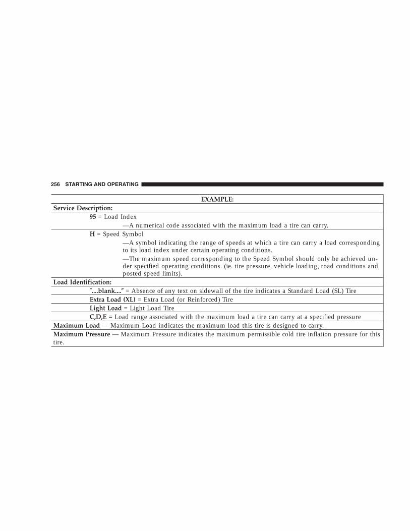
EXAMPLE:Service Description:
95 = Load Index—A numerical code associated with the maximum load a tire can carry.
H = Speed Symbol—A symbol indicating the range of speeds at which a tire can carry a load correspondingto its load index under certain operating conditions.—The maximum speed corresponding to the Speed Symbol should only be achieved un-der specified operating conditions. (ie. tire pressure, vehicle loading, road conditions andposted speed limits).
Load Identification:�....blank....� = Absence of any text on sidewall of the tire indicates a Standard Load (SL) TireExtra Load (XL) = Extra Load (or Reinforced) TireLight Load = Light Load TireC,D,E = Load range associated with the maximum load a tire can carry at a specified pressure
Maximum Load — Maximum Load indicates the maximum load this tire is designed to carry.Maximum Pressure — Maximum Pressure indicates the maximum permissible cold tire inflation pressure for thistire.
256 STARTING AND OPERATING

Tire Identification Number (TIN)The TIN may be found on one or both sides of the tirehowever the date code may only be on one side. Tires withwhite sidewalls will have the full TIN including date code
located on the white sidewall side of the tire. Look for theTIN on the outboard side of black sidewall tires as mountedon the vehicle. If the TIN is not found on the outboard sidethen you will find it on the inboard side of the tire.
EXAMPLE:DOT MA L9 ABCD 0301
DOT = Department of Transportation—This symbol certifies that the tire is in compliance with the U.S. Department of Transportation tiresafety standards, and is approved for highway use.
MA = Code representing the tire manufacturing location.(2 digits)L9 = Code representing the tire size.(2 digits)ABCD = Code used by tire manufacturer.(1 to 4 digits)03 = Number representing the week in which the tire was manufactured.(2 digits)
—03 means the 3rd week.01 = Number representing the year in which the tire was manufactured.(2 digits)
—01 means the year 2001.—Prior to July 2000, tire manufacturers were only required to have 1 number to represent the year inwhich the tire was manufactured. Example: 031 could represent the 3rd week of 1981 or 1991.
STARTING AND OPERATING 257
5

Tire Loading and Tire Pressure
Tire Placard Location
NOTE: The proper cold tire inflation pressure for pas-senger cars is listed on either the face of the driver’s dooror the driver’s side “B” pillar. For vehicles other thanpassenger cars, the cold tire inflation pressures are listedon either the shutface of the driver’s door, the “B” pillar,the Certification Label or in the Tire Inflation Pressuresbrochure in the glove compartment.
Tire Placard Location
258 STARTING AND OPERATING

Tire and Loading Information Placard
This placard tells you important information about the:1) number of people that can be carried in the vehicle2) the total weight your vehicle can carry3) the tire size designed for your vehicle4) the cold tire inflation pressures for the front, rearand spare tires.
LoadingThe vehicle maximum load on the tire must not exceedthe load carrying capacity of the tire on your vehicle. Youwill not exceed the tire’s load carrying capacity if youadhere to the loading conditions, tire size and cold tireinflation pressures specified on the Tire and LoadingInformation placard and the Vehicle Loading section ofthis manual.
NOTE: Under a maximum loaded vehicle condition,gross axle weight ratings (GAWR’s) for the front and rearaxles must not be exceeded. For further information onGAWR’s, vehicle loading and trailer towing, see theVehicle Loading section of this manual.
To determine the maximum loading conditions of yourvehicle, locate the statement “The combined weight ofoccupants and cargo should never exceed XXX kg or XXXlbs.” on the Tire and Loading Information placard. The
Tire and Loading Information
STARTING AND OPERATING 259
5

combined weight of occupants, cargo/luggage andtrailer tongue weight (if applicable) should never exceedthe weight referenced here.
Steps for Determining Correct Load Limit
1. Locate the statement “The combined weight of occu-pants and cargo should never exceed XXX pounds” onyour vehicle’s placard.
2. Determine the combined weight of the driver andpassengers that will be riding in your vehicle.
3. Subtract the combined weight of the driver and pas-sengers from XXX kilograms or XXX pounds.
4. The resulting figure equals the available amount ofcargo and luggage load capacity. For example, if “XXX”amount equals 1400 lbs. and there will be five 150 lb.passengers in your vehicle, the amount of available cargoand luggage load capacity is 650 lb. (since 5 x 150 = 750,and 1400 – 750 = 650 lb.)
5. Determine the combined weight of luggage and cargobeing loaded on the vehicle. That weight may not safelyexceed the available cargo and luggage load capacitycalculated in step 4.
6. If your vehicle will be towing a trailer, load from yourtrailer will be transferred to your vehicle. Consult thismanual to determine how this reduces the availablecargo and luggage load capacity of your vehicle.
NOTE: The following table shows examples on how tocalculate total load, cargo/luggage and towing capacitiesof your vehicle with varying seating configurations andnumber and size of occupants. This table is for illustra-tion purposes only and may not be accurate for theseating and load carry capacity of your vehicle.
NOTE: For the following example the combined weightof occupants and cargo should never exceed 865 lbs. (392Kg).
260 STARTING AND OPERATING

STARTING AND OPERATING 261
5

WARNING!
Overloading of your tires is dangerous. Overloadingcan cause tire failure, affect vehicle handling, andincrease your stopping distance. Use tires of therecommended load capacity for your vehicle. Neveroverload them.
TIRES — GENERAL INFORMATIONProper tire inflation pressure is essential to the safe andsatisfactory operation of your vehicle. Three primaryareas are affected by improper tire pressure:
1. Safety—
WARNING!
Improperly inflated tires are dangerous and cancause accidents.
• Under inflation increases tire flexing and canresult in tire failure.
• Over inflation reduces a tire’s ability to cushionshock. Objects on the road and chuck holes can causedamage that results in tire failure.
• Unequal tire pressures can cause steering prob-lems. You could lose control of your vehicle.
• Overinflated or under inflated tires can affectvehicle handling and can fail suddenly, resulting inloss of vehicle control.
Always drive with each tire properly inflated.
262 STARTING AND OPERATING

2. Economy—Improper inflation pressures can cause uneven wearpatterns to develop across the tire tread. These abnormalwear patterns will reduce tread life resulting in a need forearlier tire replacement. Under inflation also increasestire rolling resistance and results in higher fuel consump-tion.
3. Ride Comfort and Vehicle Stability—Proper tire inflation contributes to a comfortable ride.Over inflation produces a jarring and uncomfortable ride.Both under inflation and over inflation affect the stabilityof the vehicle and can produce a feeling of sluggishresponse or over responsiveness in the steering.
Unequal tire pressures can cause erratic and unpredict-able steering response.
Unequal tire pressure from side to side may cause thevehicle to drift left or right.
Tire Inflation PressuresThe proper cold tire inflation pressure is listed on eitherthe face of the driver’s door, or the driver’s side “B” pillar.
The “Cold Inflation Pressure” of each tire should bechecked and adjusted at least once every month. Check
Tire Placard Location
STARTING AND OPERATING 263
5
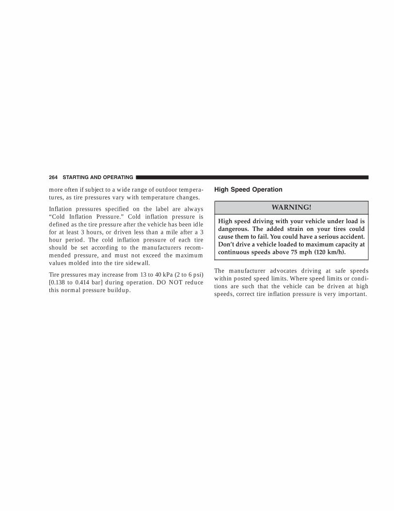
more often if subject to a wide range of outdoor tempera-tures, as tire pressures vary with temperature changes.
Inflation pressures specified on the label are always“Cold Inflation Pressure.” Cold inflation pressure isdefined as the tire pressure after the vehicle has been idlefor at least 3 hours, or driven less than a mile after a 3hour period. The cold inflation pressure of each tireshould be set according to the manufacturers recom-mended pressure, and must not exceed the maximumvalues molded into the tire sidewall.
Tire pressures may increase from 13 to 40 kPa (2 to 6 psi)[0.138 to 0.414 bar] during operation. DO NOT reducethis normal pressure buildup.
High Speed Operation
WARNING!
High speed driving with your vehicle under load isdangerous. The added strain on your tires couldcause them to fail. You could have a serious accident.Don’t drive a vehicle loaded to maximum capacity atcontinuous speeds above 75 mph (120 km/h).
The manufacturer advocates driving at safe speedswithin posted speed limits. Where speed limits or condi-tions are such that the vehicle can be driven at highspeeds, correct tire inflation pressure is very important.
264 STARTING AND OPERATING

Radial-Ply Tires
WARNING!
Combining radial ply tires with other types of tireson your vehicle will cause your vehicle to handlepoorly. The instability could cause an accident. Al-ways use radial tires in sets of four. Never combinethem with other types of tires.
Cuts and punctures in radial tires are repairable only inthe tread area because of sidewall flexing. Consult yourdealer for radial tire repairs.
Tire SpinningWhen stuck in mud, sand, snow, or ice conditions, do notspin your vehicle’s wheels above 35 mph (55 km/h).
WARNING!
Fast spinning tires can be dangerous. Forces gener-ated by excessive wheel speeds may cause tire dam-age or failure. A tire could explode and injuresomeone. Do not spin your vehicle’s wheels fasterthan 35 mph (55 km/h) when you are stuck, and donot let anyone near a spinning wheel no matter whatthe speed.
STARTING AND OPERATING 265
5

Tread Wear IndicatorsThese indicators are narrow strips 1/16 inch (1.6 mm)thick and are found in the tread pattern grooves.
When the tread pattern is worn down to these treadwearindicators, the tires should be replaced.
Overloading your vehicle, long trips in very hot weather,and driving on bad roads may result in greater wear.
Replacement TiresThe tires on your new vehicle provide a balance of manycharacteristics. They should be inspected regularly forwear and correct inflation pressure. The manufacturerstrongly recommends that you use tires equivalent to theoriginals in quality and performance when replacementis needed (see section on tread wear indicators). Failureto use equivalent replacement tires may adversely affectthe safety, handling, ride and fuel economy of yourvehicle. We recommend that you contact your originalequipment tire dealer on any questions you may have ontire specifications or capability.
266 STARTING AND OPERATING

WARNING!
• Do not use a tire, wheel size or rating other than thatspecified for your vehicle. Some combinations of unap-proved tires and wheels may change suspension dimen-sions and performance characteristics, resulting inchanges to steering, handling, and braking of yourvehicle. This can cause unpredictable handling andstress to steering and suspension components. Youcould lose control and have an accident resulting inserious injury or death. Use only the tire and wheelsizes with load ratings approved for your vehicle.
• Never use a tire smaller than the minimum tire sizelisted on your vehicle’s tire label. Using a smaller tirecould result in tire overloading and failure. You couldlose control and have an accident.
• Failure to equip your vehicle with tires having adequatespeed capability can result in sudden tire failure andloss of vehicle control.
• Overloading your tires is dangerous. Overloading cancause tire failure. Use tires of the recommended loadcapacity for your vehicle - never overload them.
CAUTION!
Replacing original tires with tires of a different sizemay result in false speedometer and odometer read-ings. Check with your dealer before replacing tireswith a different size.
Alignment and BalanceThe suspension components of your vehicle should beinspected and aligned when needed, to obtain maximumtire tread life.
Poor suspension alignment may result in:
• reduced tread life;
• uneven tire wear, such as feathering and one-sidedwear;
• vehicle pull to the right or to the left.
STARTING AND OPERATING 267
5
Tires may also cause the vehicle to pull left or right.Alignment will not correct this problem. See your dealerfor proper diagnosis of the problem.
Improper alignment will not normally cause vehiclevibration, which may be a result of tire and wheelout-of-balance. Proper balancing will reduce vibrationand avoid tire cupping and spotty wear.
TIRE PRESSURE MONITOR SYSTEM — IFEQUIPPED
Tire Pressure Monitoring — Base SystemThe Tire Pressure Monitor System (TPM) system useswireless technology with wheel rim mounted electronicsensors to monitor tire pressure levels (EXCLUDINGTHE SPARE TIRE). Sensors, mounted to each wheel aspart of the valve stem, transmit tire pressure readings tothe Receiver Module.
NOTE: It is particularly important, for you to check thetire pressure in all of your tires regularly and to maintainthe proper pressure.
The Tire Pressure Monitoring Indicator Lamp willilluminate in the instrument cluster, and an au-dible chime will be activated when one or more
tire pressures is low. The Tire Pressure Monitoring Indi-cator Lamp will flash on and off for ten seconds when asystem fault is detected. The flash cycle will repeat everyten minutes or until the fault condition is removed andreset.
The Tire Pressure Monitoring System consists of thefollowing components:
• Receiver Module
• 4/5 Wheel Sensors
• Amber Colored Tire Pressure Monitoring IndicatorLamp
268 STARTING AND OPERATING

The system will consist of tire pressure monitoringsensors attached to each wheel through the valve stemmounting hole, a central receiver module and an ambercolored Indicator Lamp. A sensor is located in the sparewheel if the vehicle is equipped with a matching full sizespare wheel and tire assembly.
NOTE: For vehicles with optional wheel/tire sizes andsignificantly different tire placard pressures, the placardpressure value and the low-pressure threshold value isre-programmable at your authorized dealer to accommo-date the customer selected wheel/tire combinations rec-ommended by DaimlerChrysler.
CAUTION!
The TPM system has been optimized for the originalequipment tires and wheels. TPM system pressureshave been established for the tire size equipped onyour vehicle. Undesirable system operation or sen-sor damage may result when using replacementequipment that is not of the same size, type, and/orstyle. After-market wheels can cause sensor damage.Do not use tire sealant from a can, or balance beadsif your vehicle is equipped with a TPM system, asdamage to the sensors may result.
STARTING AND OPERATING 269
5

CAUTION!
After inspecting or adjusting the tire pressure al-ways reinstall the valve stem cap. This will preventmoisture and dirt from entering the valve stem,which could damage the wheel rim sensor.
NOTE:• The TPM system can inform the driver of a low tire
pressure condition.
• The TPM system is not intended to replace normal tirecare and maintenance, nor to provide warning of a tirefailure or condition.
• The TPM system should not be used as a tire pressuregauge while adjusting your tire pressure.
Tire Pressure Monitoring — Premium SystemThe Tire Pressure Monitor System (TPM) system useswireless technology with wheel rim mounted electronicsensors to monitor tire pressure levels. Sensors mountedto each wheel as part of the valve stem transmit tirepressure readings to the Receiver Module. The wheelsensors monitor tire pressure, and status for all fouractive road tires and the spare tire. The spare tire pressureis monitored, but not displayed.
NOTE: It is particularly important, for you to check thetire pressure in all of your tires regularly and to maintainthe proper pressure.
The Tire Pressure Monitoring Indicator Lamp willilluminate in the instrument cluster, and an au-dible chime will be activated when one or more
tire pressures is low. The Tire Pressure Monitoring Indi-cator Lamp will flash on and off for ten seconds when a
270 STARTING AND OPERATING

system fault is detected. The flash cycle will repeat everyten minutes or until the fault condition is removed andreset.
The Tire Pressure Monitoring System consists of thefollowing components:
• Receiver Module
• 4/5 Wheel Sensors
• 4 Wheel Sensor Trigger Modules
• Tire Pressure Monitoring System Display Messages inthe EVIC
• Amber Colored Tire Pressure Monitoring IndicatorLamp
The system consists of tire pressure monitoring sensorsattached to each wheel through the valve stem mountinghole, a central receiver module, Wheel Sensor TriggerModules mounted in three of the four wheel wells,
various Tire Pressure Monitoring System Display Mes-sages in the EVIC, and an amber colored Indicator Lamp.A sensor shall be installed in the spare wheel if thevehicle is equipped with a matching full size spare wheeland tire assembly.
NOTE: For vehicles with optional wheel/tire sizes andsignificantly different tire placard pressures, the placardpressure value and the low-pressure threshold value isre-programmable at your authorized dealer to accommo-date the customer selected wheel/tire combinations rec-ommended by DaimlerChrysler.
The following �warnings� will cause a text message to bedisplayed, an audible chime to sound and the tire pres-sure Indicator Lamp to illuminate. The audible chimewill occur once every ignition cycle for each �warning�detected. The tire pressure Indicator Lamp will illumi-nate continuously (solid) and shall remain illuminateduntil the warning condition is removed/reset.
STARTING AND OPERATING 271
5

NOTE: The Indicator Lamp will only illuminate for thefour active road tires. A low spare tire pressure will notcause the Indicator Lamp to illuminate
When the appropriate conditions exist, the ElectronicVehicle Information Center (EVIC) displays the followingmessages.
LEFT FRONT, LEFT REAR, RIGHT FRONT,RIGHT REAR LOW PRESSURE, SPARE LOWPRESSUREOne or more of these messages will be displayed in theEVIC if a low tire pressure condition exists in one or moretires.
Inspect all tires for proper inflation pressure, once theproper tire pressure has been set, the TPM systemwarning will reset automatically when the vehicle hasbeen driven for at least 2 minutes at or above 15 mph (24km/h).
CHECK TPM SYSTEMSee your authorized dealer when this message appears inthe EVIC. This message indicates that a system faultcondition has been detected.
CAUTION!
The TPM system has been optimized for the originalequipment tires and wheels. TPM system pressureshave been established for the tire size equipped onyour vehicle. Undesirable system operation or sen-sor damage may result when using replacementequipment that is not of the same size, type, and/orstyle. After-market wheels can cause sensor damage.Do not use tire sealant from a can, or balance beadsif your vehicle is equipped with a TPM system, asdamage to the sensors may result.
272 STARTING AND OPERATING

CAUTION!
After inspecting or adjusting the tire pressure al-ways reinstall the valve stem cap. This will preventmoisture and dirt from entering the valve stem,which could damage the wheel rim sensor.
NOTE:• The TPM system can inform the driver of a low tire
pressure condition.
• The TPM system is not intended to replace normal tirecare and maintenance, nor to provide warning of a tirefailure or condition.
• The TPM system should not be used as a tire pressuregauge while adjusting your tire pressure.
General InformationThis device complies with part 15 of the FCC rules andRSS 210 of Industry Canada. Operation is subject to thefollowing conditions:
• This device may not cause harmful interference.
• This device must accept any interference received,including interference that may cause undesired op-eration.
The tire pressure sensors are covered under one of thefollowing licenses:
United States . . . . . . . . . . . . . . . . . . . . . KR5S120123Canada . . . . . . . . . . . . . . . . . . . . . . . . 2671-S120123
STARTING AND OPERATING 273
5

TIRE CHAINS
CAUTION!
To avoid damage to your vehicle or tires, observe the followingprecautions:
• Because of restricted chain clearance between tires and othersuspension components, it is important that only chains ingood condition are used. Broken chains can cause seriousdamage. Stop the vehicle immediately if noise occurs that couldindicate chain breakage. Remove the damaged parts of thechain before further use.
• Install chains on the rear wheels as tightly as possible and thenretighten after driving about 1⁄2 mile (0.8 km).
• Do not exceed 30 mph (48 km/h).
• Drive cautiously and avoid severe turns and large bumps,especially with a loaded vehicle.
• Do not drive for prolonged period on dry pavement.
• Observe the tire chain manufacturer’s instructions on themethod of installation, operating speed, and conditions for use.Always use the lower suggested operating speed of the chainmanufacturer if different than the speed recommended by themanufacture.
Tire chains that are recommended for this vehicle arelisted below:
• Mopar� P/N 82206828 with P235/70R16 and P235/65R17 tires.
• Mopar� P/N 82207074 with P215/75R16 tires.
NOTE: In order to avoid damage to tires, chains, andyour vehicle do not drive for a prolonged period of timeon dry pavement. Observe the tire chain manufacturer’sinstructions on method of installation, operating speed,and conditions for usage.
Always use the lower suggested operating speed if boththe chain manufacturer and vehicle manufacturer sug-gest a maximum speed. This notice applies to all chaintraction devices, including link and cable (radial) chains.
274 STARTING AND OPERATING

TIRE ROTATION RECOMMENDATIONSTires on the front and rear axles of vehicles operate atdifferent loads and perform different steering, handling,and braking functions. For these reasons, they wear atunequal rates, and develop irregular wear patterns.
These effects can be reduced by timely rotation of tires.The benefits of rotation are especially worthwhile withaggressive tread designs such as those on On/Off Roadtype tires. Rotation will increase tread life, help to main-tain mud, snow, and wet traction levels, and contribute toa smooth, quiet ride.
2.4L/3.7L EnginesFollow the recommended tire rotation frequency for yourtype of driving found in the “Maintenance Schedules”Section of this manual. More frequent rotation is permis-sible if desired. The reasons for any rapid or unusual wearshould be corrected prior to rotation being performed.
2.8L Turbo Diesel EnginesRotate the tires every 6,000 miles (10 000 km).
NOTE: The Premium Tire Pressure Monitor System willautomatically locate the pressure values displayed in thecorrect vehicle position following a tire rotation.
STARTING AND OPERATING 275
5

The suggested rotation method is the “forward-cross”shown in the following diagram.
FUEL REQUIREMENTS (GASOLINE ENGINES)Your engine is designed to meet all emis-sions regulations and provide excellentfuel economy and performance when us-ing high quality unleaded gasoline havingan octane rating of 87. The use of premiumgasoline is not recommended. The use of
premium gasoline will provide no benefit over highquality regular gasoline, and in some circumstances mayresult in poorer performance.
Mid-grade gasoline (89 octane) will enhance engine per-formance during the following conditions (3.7L Only):
• Hot weather
• Towing
• Hard accelerations
• Hilly terrain
• Low humidity
276 STARTING AND OPERATING

Light spark knock at low engine speeds is not harmful toyour engine. However, continued heavy spark knock athigh speeds can cause damage and immediate service isrequired.
Poor quality gasoline can cause problems such as hardstarting, stalling and hesitations. If you experience thesesymptoms, try another brand of gasoline before consid-ering service for the vehicle.
Over 40 auto manufacturer’s world wide have issued andendorsed consistent gasoline specifications (the World-wide Fuel Charter, WWFC) to define fuel propertiesnecessary to deliver enhanced emissions, performance,and durability for your vehicle. The manufacturer recom-mends the use of gasoline that meets the WWFC speci-fications if they are available.
Reformulated GasolineMany areas of the country require the use of cleanerburning gasoline referred to as Reformulated Gasoline.Reformulated gasoline contains oxygenates, and is spe-cifically blended to reduce vehicle emissions and im-prove air quality.
The manufacturer strongly supports the use of reformu-lated gasoline. Properly blended reformulated gasolinewill provide excellent performance and durability for theengine and fuel system components.
STARTING AND OPERATING 277
5

Gasoline/Oxygenate BlendsSome fuel suppliers blend unleaded gasoline with oxy-genates such as 10% ethanol, MTBE, and ETBE. Oxygen-ates are required in some areas of the country during thewinter months to reduce carbon monoxide emissions.Fuels blended with these oxygenates may be used inyour vehicle.
CAUTION!
DO NOT use gasoline containing METHANOL.Gasoline containing methanol may damage criticalfuel system components.
MMT In GasolineMMT is a manganese containing metallic additive that isblended into some gasoline to increase octane. Gasolineblended with MMT provides no performance advantagebeyond gasoline of the same octane number withoutMMT. Gasoline blended with MMT reduces spark pluglife and reduces emission system performance in somevehicles. The manufacturer recommends that gasolinewithout MMT be used in your vehicle. The MMT contentof gasoline may not be indicated on the gasoline pump,therefore, you should ask your gasoline retailer whetheror not his/her gasoline contains MMT.
It is even more important to look for gasoline withoutMMT in Canada because MMT can be used at levelshigher than allowed in the United States. MMT is pro-hibited in Federal and California reformulated gasoline.
278 STARTING AND OPERATING

Materials Added To FuelAll gasoline sold in the United States is required tocontain effective detergent additives. Use of additionaldetergents or other additives is not needed under normalconditions.
Fuel System Cautions
CAUTION!
Follow these guidelines to maintain your vehicle’sperformance:
• The use of leaded gas is prohibited by Federal law.Using leaded gasoline can impair engine performance,damage the emission control system.
• An out-of-tune engine, or certain fuel or ignitionmalfunctions, can cause the catalytic converter tooverheat. If you notice a pungent burning odor orsome light smoke, your engine may be out of tune ormalfunctioning and may require immediate service.Contact your dealer for service assistance.
• The use of fuel additives which are now being sold asoctane enhancers is not recommended. Most of theseproducts contain high concentrations of methanol.Fuel system damage or vehicle performance problemsresulting from the use of such fuels or additives is notthe responsibility of the manufacturer.
NOTE: Intentional tampering with emissions controlsystems can result in civil penalties being assessedagainst you.
STARTING AND OPERATING 279
5

Carbon Monoxide Warnings
WARNING!
Carbon monoxide (CO) in exhaust gases is deadly.Follow the precautions below to prevent carbonmonoxide poisoning:
• Do not inhale exhaust gases. They contain carbonmonoxide, a colorless and odorless gas which can kill.Never run the engine in a closed area, such as agarage, and never sit in a parked vehicle with theengine running for an extended period. If the vehicle isstopped in an open area with the engine running formore than a short period, adjust the ventilation systemto force fresh, outside air into the vehicle.
• Guard against carbon monoxide with proper mainte-nance. Have the exhaust system inspected every time
the vehicle is raised. Have any abnormal conditionsrepaired promptly. Until repaired, drive with all sidewindows fully open.
• Keep the swing gate closed when driving your vehicleto prevent carbon monoxide and other poisonousexhaust gases from entering the vehicle.
FUEL REQUIREMENTS (DIESEL ENGINES)Use good quality diesel fuel from a reputable supplier.For most year-round service, No. 2 diesel fuel meetingASTM specification D-975 will provide good perfor-mance. If the vehicle is exposed to extreme cold (below20°F or -7°C), or is required to operate at colder-than-normal conditions for prolonged periods, use climatizedNo. 2 diesel fuel or dilute the No. 2 diesel fuel with 50%No. 1 diesel fuel. This will provide better protection fromfuel gelling or wax-plugging of the fuel filters.
280 STARTING AND OPERATING

NOTE: DaimlerChrysler Corporation recommends thatthis vehicle should be operated using Diesel fuel with 15ppm Sulfur or less, where it is available.
WARNING!
Do not use alcohol or gasoline as a fuel blendingagent. They can be unstable under certain conditionsand hazardous or explosive when mixed with dieselfuel.
Diesel fuel is seldom completely free of water. To preventfuel system trouble, drain the accumulated water fromthe fuel/water separator using the fuel/water separatordrain provided. If you buy good quality fuel and followthe cold weather advice above, fuel conditioners shouldnot be required in your vehicle. If available in your area,a high cetane “premium” diesel fuel may offer improvedcold-starting and warm-up performance.
FUEL TANK FILLER CAP (GAS CAP)
WARNING!
To avoid fuel spillage and overfilling, do not “topoff” the fuel tank after filling.
CAUTION!
DO NOT put gasoline in your diesel vehicle (ifequipped). If you accidentally put gasoline in yourvehicle, DO NOT start the engine. This will causedamage to the fuel system. Have the fuel systemflushed.
STARTING AND OPERATING 281
5

The gas cap is located behind the fuel filler door, on theleft side of the vehicle. If the gas cap is lost or damaged,be sure the replacement cap has been designed for usewith this vehicle.
When tightening the gas cap, tighten until 2 or 3 clicksare heard to insure that the cap is properly seated.
NOTE: A loose gas cap may cause the “MalfunctionIndicator Light” to illuminate.
Fuel Filler Cap
282 STARTING AND OPERATING

Loose Fuel Filler Cap MessageIf the vehicle diagnostic system determines that the fuelfiller cap is loose, improperly installed, or damaged, a“CHECK GAS CAP” message will be displayed in theEVIC (Electronic Vehicle Information Center). Refer to“Overhead Console” in Section 3 of this manual. Tightenthe fuel filler cap properly and press the odometer resetbutton to turn the message off. If the problem continues,the message will appear the next time the vehicle isstarted. Refer to “Onboard Diagnostic System — OBDII”in Section 7 of this manual for more information.
CAUTION!
Damage to the fuel system or emission controlsystem could result from using an improper fueltank filler cap (gas cap). A poorly fitting cap could letimpurities into the fuel system.
WARNING!
• Never add fuel when the engine is running.
• Never have any smoking materials lit in or nearthe vehicle when the fuel cap is removed or thetank filled.
TRAILER TOWINGIn this section you will find information on limits to thetype of towing you can reasonably do with your vehicle.Before towing a trailer, carefully review this informationto tow your load as efficiently and safely as possible.
To maintain warranty coverage, follow the requirementsand recommendations in this manual concerning ve-hicles used for trailer towing.
STARTING AND OPERATING 283
5

Perform maintenance services as prescribed in the“Maintenance Schedules” section. When your vehicle isused for trailer towing, never exceed the gross axleweight rating (GAWR) by the addition of:
• The tongue weight of the trailer.
• The weight of any other type of cargo or equipmentput in or on your vehicle.
Remember that everything put in or on the trailer adds tothe load on your vehicle.
Warranty RequirementsThe manufacturer’s warranty will apply to vehicles usedto tow trailers for noncommercial use, however thefollowing conditions must be met:
• The “D” Overdrive range can be selected when tow-ing. However, if frequent shifting occurs select the“O/D Off” function or move the shift lever to the nextlower position to eliminate excessive automatic trans-mission shifting. This action will also reduce thepossibility of transmission overheating and providebetter engine braking. Refer to “Transmission Shift-ing” in this section for additional information.
• A load equalizing hitch is recommended for loadedtrailer weights above 1,000 lbs (454 kg).
284 STARTING AND OPERATING
CAUTION!
If the trailer weighs more than 1,000 lbs (454 kg)loaded, it should have its own brakes and theyshould be of adequate capacity. Failure to do thiscould lead to accelerated brake lining wear, higherbrake pedal effort, and longer stopping distances.
WARNING!
Connecting trailer brakes to your vehicle’s hydraulicbrake lines can overload your brake system andcause it to fail. You might not have brakes when youneed them and could have an accident.
• Whenever you pull a trailer, regardless of the trailersize, stop lights and turn signals on the trailer aremandatory for motoring safety.
• Follow the maintenance intervals in schedule “B” forchanging the automatic transmission fluid and filter, ifyou REGULARLY tow a trailer for more than 45minutes of continuous operation.
STARTING AND OPERATING 285
5

Minimum Vehicle Requirements for Trailer Towing
286 STARTING AND OPERATING
RECREATIONAL TOWING (BEHINDMOTORHOME, ETC.)
Towing – 2WD Models
Recreational towing is not allowed. Towing with therear wheels on the ground can result in severe transmis-sion damage.
Towing — 4WD Models
CAUTION!
Internal damage to the transfer case will occur if afront or rear wheel lift is used when recreationaltowing.
NOTE: The transfer case must be shifted into N (Neu-tral), and the transmission must be shifted into P (Park)
(for automatic transmission) or into any forward gear (formanual transmission) for recreational towing.
Shifting Into Neutral (N)Use the following procedure to prepare your vehicle forrecreational towing.
CAUTION!
It is necessary to follow these steps to be certain thatthe transfer case is fully in N (Neutral) beforerecreational towing to prevent damage to internalparts.
1. Depress brake pedal.
2. Shift transmission into N (Neutral).
3. Shift transfer case lever into N (Neutral).
4. Start engine.
STARTING AND OPERATING 287
5

5. Shift automatic transmission into D (Drive) or manualtransmission into any forward gear.
6. Release brake pedal and ensure that there is no vehiclemovement.
7. Shut the engine OFF and place the ignition key intothe unlocked OFF position.
8. Shift automatic transmission into P (Park) or ensuremanual transmission is in any forward gear.
9. Apply parking brake.
10. Attach vehicle to the tow vehicle with tow bar.
11. Release parking brake.
CAUTION!
Transmission damage may occur if the automatictransmission is shifted into P (Park) with the transfercase in N (Neutral) and the engine running. With thetransfer case in N (Neutral) ensure that the engine isOFF prior to shifting the transmission into P (Park)(refer to steps 7 – 8 above).
Shifting Out Of Neutral (N)Use the following procedure to prepare your vehicle fornormal usage.
1. Shift transmission into N (Neutral).
2. Turn engine off.
3. Shift transfer case lever to desired position.
4. Shift automatic transmission into P (Park).
288 STARTING AND OPERATING

5. Start engine.
6. Shift automatic transmission into D (Drive) or manualtransmission into any forward gear.
WARNING!
You or others could be injured if you leave thevehicle unattended with the transfer case in the N(Neutral) position without first fully engaging theparking brake. The transfer case N (Neutral) positiondisengages both the front and rear driveshafts fromthe powertrain and will allow the vehicle to moveregardless of the transmission position. The parkingbrake should always be applied when the driver isnot in the vehicle.
CAUTION!
Do not use a bumper mounted clamp-on tow bar onyour vehicle. The bumper face bar will be damaged.
SNOW PLOWSnow plows, winches, and other aftermarket equipmentshould not be added to the front end of your vehicle. Theairbag crash sensors may be affected by the change in thefront end structure. The airbags could deploy unexpect-edly or could fail to deploy during a collision.
STARTING AND OPERATING 289
5

WARNING!
Do not add a snow plow, winches, or any otheraftermarket equipment to the front of your vehicle.This could adversely affect the functioning of theairbag system and you could be injured.
290 STARTING AND OPERATING

WHAT TO DO IN EMERGENCIES
CONTENTS
� Hazard Warning Flashers . . . . . . . . . . . . . . . . . 292
� If Your Engine Overheats . . . . . . . . . . . . . . . . . 293
� Jacking And Tire Changing . . . . . . . . . . . . . . . . 294
▫ Jack Location . . . . . . . . . . . . . . . . . . . . . . . . 295
▫ Spare Tire Stowage . . . . . . . . . . . . . . . . . . . . 295
▫ Preparations For Jacking . . . . . . . . . . . . . . . . 296
▫ Jacking Instructions . . . . . . . . . . . . . . . . . . . . 296
� Jump Starting Procedure . . . . . . . . . . . . . . . . . . 299
� Emergency Tow Hooks — If Equipped . . . . . . . . 301
� Towing A Disabled Vehicle . . . . . . . . . . . . . . . . 302
▫ 2WD Models Only . . . . . . . . . . . . . . . . . . . . 302
▫ 4WD Models Only . . . . . . . . . . . . . . . . . . . . 302
6

HAZARD WARNING FLASHERSYour vehicle’s hazard warning flasher is an emergencywarning system. When you activate it, all front and reardirectional signals will flash intermittently. Use it whenyour vehicle is disabled on or near the road. It warnsother drivers to steer clear of you and your vehicle. Thisis an emergency warning system, not to be used when thevehicle is in motion.
To activate the warning flashers, press the button on theinstrument panel (between center air outlets). To turn thewarning flashers off, press the button again.
NOTE: With extended use, the flashers may run downyour battery.
Hazard Warning Switch
292 WHAT TO DO IN EMERGENCIES

IF YOUR ENGINE OVERHEATSIn any of the following situations, you can reduce thepotential for overheating by taking the appropriate ac-tion.
• On the highways — Slow down.
• In city traffic — While stopped, put transmission in N(Neutral), but do not increase engine idle speed.
NOTE: There are steps that you can take to slow downan impending overheat condition. If your air conditioneris on, turn it off. The air conditioning system adds heat tothe engine cooling system and turning off the A/Cremoves this heat. You can also turn the TemperatureControl to maximum heat, the Mode Control to floor, andthe Fan Control to High. This allows the heater core to actas a supplement to the radiator and aids in removing heatfrom the engine cooling system.
If the pointer rises to the “H” (hot mark) on a vehicleequipped with a gasoline engine , pull over and stop thevehicle. Do not turn the engine off. Idle the vehicle withthe air conditioning turned off, until the pointer dropsback into the normal range.
CAUTION!
Driving with a hot cooling system could damageyour vehicle. If the temperature gauge reads “H”,pull over and stop the vehicle. Idle the vehicle withthe air conditioner turned off until the pointer dropsback into the normal range. If the pointer remains onthe “H”, and you hear continuous chimes, turn theengine off immediately, and call for service.
WHAT TO DO IN EMERGENCIES 293
6

If the coolant temperature of a vehicle equipped with adiesel engine approaches the “H” (hot mark) a warningchime will sound to alert the driver. The air conditioningsystem will turn off automatically and power loss willoccur until the engine temperature returns to the normalrange.
If the overheating condition persists a continuous chimewill sound to alert the driver. Reduce the vehicle speedand or stop the vehicle while allowing the engine to idleand cool the engine.
JACKING AND TIRE CHANGING
WARNING!
• Getting under a jacked-up vehicle is dangerous.The vehicle could slip off the jack and fall on you.You could be crushed. Never get any part of yourbody under a vehicle that is on a jack. If you needto get under a raised vehicle, take it to a servicecenter where it can be raised on a lift.
• The jack is designed to use as a tool for changingtires only. The jack should not be used to lift thevehicle for service purposes. The vehicle shouldbe jacked on a firm level surface only. Avoid ice orslippery areas.
294 WHAT TO DO IN EMERGENCIES

Jack LocationThe scissor-type jack, and tire changing tools are storedbeneath the right rear seat. To remove the jack from itsstowage position, turn the thumb screw counterclock-wise to loosen jack assembly and then remove it.
Spare Tire StowageTo remove the spare tire from the carrier, remove the tirecover, if equipped, and remove the lug nuts with the lugwrench turning them counterclockwise.
Jack Storage LocationSpare Tire Mounting
WHAT TO DO IN EMERGENCIES 295
6
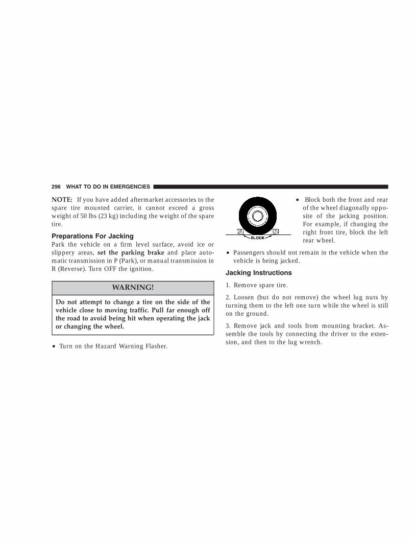
NOTE: If you have added aftermarket accessories to thespare tire mounted carrier, it cannot exceed a grossweight of 50 lbs (23 kg) including the weight of the sparetire.
Preparations For JackingPark the vehicle on a firm level surface, avoid ice orslippery areas, set the parking brake and place auto-matic transmission in P (Park), or manual transmission inR (Reverse). Turn OFF the ignition.
WARNING!
Do not attempt to change a tire on the side of thevehicle close to moving traffic. Pull far enough offthe road to avoid being hit when operating the jackor changing the wheel.
• Turn on the Hazard Warning Flasher.
• Block both the front and rearof the wheel diagonally oppo-site of the jacking position.For example, if changing theright front tire, block the leftrear wheel.
• Passengers should not remain in the vehicle when thevehicle is being jacked.
Jacking Instructions
1. Remove spare tire.
2. Loosen (but do not remove) the wheel lug nuts byturning them to the left one turn while the wheel is stillon the ground.
3. Remove jack and tools from mounting bracket. As-semble the tools by connecting the driver to the exten-sion, and then to the lug wrench.
296 WHAT TO DO IN EMERGENCIES

4. Locate the jack as shown. For the front tires, place it inthe notch on the body weld seam behind wheel to bechanged. For the rear tires, place it under the axle by thewheel to be changed. Position the jack handle on the jack.Do not raise the vehicle until you are sure the jack isfully engaged.
5. Raise the vehicle by turning the jack screw to the right.Raise the vehicle only until the tire just clears the surfaceand enough clearance is obtained to install the spare tire.Minimum tire lift provides maximum stability.
Front Jacking Location
Rear Jacking Location
WHAT TO DO IN EMERGENCIES 297
6
WARNING!
Raising the vehicle higher than necessary can makethe vehicle less stable and cause an accident. It couldslip off the jack and hurt someone near it. Raise thevehicle only enough to remove the tire.
6. Remove the lug nuts and wheel.
7. Position the spare wheel/tire on the vehicle and installlug nuts with cone-shaped end toward wheel. Lightlytighten the nuts. To avoid the risk of forcing the vehicleoff the jack, do not tighten the nuts fully until the vehiclehas been lowered.
8. Lower the vehicle by turning the jack screw to the left,and remove the jack and wheel blocks.
9. Finish tightening the lug nuts. Push down on thewrench while tightening for increased leverage. Alternate
nuts until each nut has been tightened twice. Correctwheel nut tightness is 130 N·m (95 ft. lbs). If in doubtabout the correct tightness, have them checked with atorque wrench by your authorized dealer or at a servicestation.
10. Lower the jack to it’s fully closed position.
WARNING!
A loose tire or jack, thrown forward in a collision orhard stop could endanger the occupants of the ve-hicle. Always stow the jack parts and the spare tire inthe places provided.
11. Secure the tire, jack, and tools in their proper loca-tions.
298 WHAT TO DO IN EMERGENCIES

JUMP STARTING PROCEDURE
NOTE: Check the charge indicator on the battery. If theindicator is light or yellow, replace the battery.
1. Wear eye protection and remove any metal jewelrysuch as watch bands or bracelets that might make anunintended electrical contact.
2. When boost is provided by a battery in anothervehicle, park that vehicle within booster cable reach butwithout letting the vehicles touch. Set the parking brake,place the automatic transmission in P (Park), or manualtransmission in N (Neutral), and turn the ignition to OFFfor both vehicles.
3. Turn off the heater, radio and all unnecessary electricalloads.
4. Connect one end of a jumper cable to the positiveterminal of the discharged battery. Connect the other endof the same cable to the positive terminal of the boosterbattery.
5. Connect the other cable, first to the negative terminalof the booster battery and then connect the other end toa non-paint metal surface on the engine of the vehiclewith the discharged battery. Make sure you have a goodcontact on the engine.
6. Start the engine in the vehicle which has the boosterbattery, let the engine idle a few minutes, then start theengine in the vehicle with the discharged battery.
7. When removing the jumper cables, reverse the abovesequence exactly. Be careful of the moving belts and fan.
WHAT TO DO IN EMERGENCIES 299
6

NOTE: To start the vehicle following connection of abooster battery, the Security Alarm System must first bedisabled by cycling a front door key cylinder or by usingthe keyless entry transmitter.
WARNING!
Jump starting can be dangerous. To avoid personalinjury or damage to electrical components in vehicle,observe the following warnings:
• Battery fluid is a corrosive acid solution and can burnor even blind you. Don’t allow battery fluid to contactyour eyes, skin, or clothing. Don’t lean over a batterywhen attaching clamps. If acid splashes in eyes or onskin, flush the area immediately with large amounts ofwater.
• Do not use a booster battery or any other boostersource that has a greater than 12–volt system, i.e., donot use a 24–volt power source.
• Never attempt to jump start a discharged battery thatis frozen, because it could rupture or explode duringjump starting.
• Be sure your vehicle is not touching the jump startvehicle.
• Observe all Battery Warnings in Section 7 of thismanual, while jump starting your vehicle.
300 WHAT TO DO IN EMERGENCIES

WARNING!
Do not attempt to push or tow your vehicle to get itstarted. Unburned fuel could enter the catalyticconverter and, once the engine has started, ignite anddamage the converter and vehicle.
EMERGENCY TOW HOOKS — IF EQUIPPEDIf your vehicle is equipped with tow hooks, they aremounted in the front and the rear.
CAUTION!
Tow hooks are for emergency use only, to rescue avehicle stranded off road. Do not use tow hooks fortow truck hookup or highway towing. You coulddamage your vehicle. Tow straps are recommendedwhen towing the vehicle, chains may cause vehicledamage.
WARNING!
Stand clear of vehicles when pulling with towhooks. Tow straps and chains may break, causingserious injury.
WHAT TO DO IN EMERGENCIES 301
6

TOWING A DISABLED VEHICLE
2WD Models OnlyProvided the transmission is operable, tow only in N(Neutral) at speeds not exceeding 30 mph (48 km/h), fordistances of not more than 15 miles (24 km). Towing atmore than 30 mph (48 km/h) or for more than 15 miles(24 km) can cause severe transmission damage. If thetransmission is not operable, or the vehicle must betowed faster than 30 mph (48 km/h) or farther than 15miles (24 km), tow with all four wheels OFF the ground.Acceptable methods are to tow the vehicle on a flatbed orwith one end of the vehicle raised and the other end ona towing dolly. Removing the driveshaft for towing is notrecommended since this can allow fluid to drain from thetransmission.
4WD Models OnlyThe manufacturer recommends towing with all fourwheels OFF the ground. Acceptable methods are to towthe vehicle on a flatbed or with one end of the vehicleraised and the other end on a towing dolly.
302 WHAT TO DO IN EMERGENCIES

MAINTAINING YOUR VEHICLE
CONTENTS
� 2.4L Engine . . . . . . . . . . . . . . . . . . . . . . . . . . . 306
� 3.7L Engine . . . . . . . . . . . . . . . . . . . . . . . . . . . 307
� 2.8L Turbo Diesel Engine . . . . . . . . . . . . . . . . . 308
� Onboard Diagnostic System — OBD II . . . . . . . . 309
▫ Loose Fuel Filler Cap Message . . . . . . . . . . . . 309
� Emissions Inspection And MaintenancePrograms . . . . . . . . . . . . . . . . . . . . . . . . . . . . 310
� Replacement Parts . . . . . . . . . . . . . . . . . . . . . . 311
� Dealer Service . . . . . . . . . . . . . . . . . . . . . . . . . 312
� Maintenance Procedures . . . . . . . . . . . . . . . . . . 312
▫ Engine Oil . . . . . . . . . . . . . . . . . . . . . . . . . . 312
▫ Drive Belts — Check Condition And Tension . . 316
▫ Spark Plugs . . . . . . . . . . . . . . . . . . . . . . . . . 317
▫ Catalytic Converter . . . . . . . . . . . . . . . . . . . . 317
▫ Engine Timing Belt — 2.4L Engine . . . . . . . . . 319
▫ Ignition Wiring System — 2.4L Engine . . . . . . 319
▫ Crankcase Emission Control System . . . . . . . . 319
▫ Air Cleaner Filter . . . . . . . . . . . . . . . . . . . . . 319
7

▫ Maintenance-Free Battery . . . . . . . . . . . . . . . . 320
▫ Air Conditioner Maintenance . . . . . . . . . . . . . 321
▫ Power Steering Fluid Check . . . . . . . . . . . . . . 322
▫ Driveline And Steering ComponentLubrication . . . . . . . . . . . . . . . . . . . . . . . . . . 322
▫ Body Lubrication . . . . . . . . . . . . . . . . . . . . . 323
▫ Windshield Wiper Blades . . . . . . . . . . . . . . . . 323
▫ Windshield Washers . . . . . . . . . . . . . . . . . . . 324
▫ Exhaust System . . . . . . . . . . . . . . . . . . . . . . 324
▫ Cooling System . . . . . . . . . . . . . . . . . . . . . . . 325
▫ Hoses And Vacuum/Vapor Harnesses . . . . . . . 330
▫ Brake System . . . . . . . . . . . . . . . . . . . . . . . . 330
▫ Automatic Transmission . . . . . . . . . . . . . . . . 333
▫ Hydraulic Clutch Fluid —Manual Transmission . . . . . . . . . . . . . . . . . . 335
▫ Manual Transmission . . . . . . . . . . . . . . . . . . 335
▫ Transfer Case . . . . . . . . . . . . . . . . . . . . . . . . 336
▫ Front/Rear Axle Fluid . . . . . . . . . . . . . . . . . . 337
▫ Appearance Care And Protection FromCorrosion . . . . . . . . . . . . . . . . . . . . . . . . . . . 337
� Fuse Panel . . . . . . . . . . . . . . . . . . . . . . . . . . . 342
▫ Interior Fuses . . . . . . . . . . . . . . . . . . . . . . . . 342
▫ Underhood Fuses(Power Distribution Center) . . . . . . . . . . . . . . 345
� Vehicle Storage . . . . . . . . . . . . . . . . . . . . . . . . 349
� Replacement Bulbs . . . . . . . . . . . . . . . . . . . . . . 350
304 MAINTAINING YOUR VEHICLE

� Bulb Replacement . . . . . . . . . . . . . . . . . . . . . . 351
▫ Head Light . . . . . . . . . . . . . . . . . . . . . . . . . . 351
▫ Front Turn Signal . . . . . . . . . . . . . . . . . . . . . 352
▫ Front Fog Light (Front Fascia Mounted) . . . . . 353
▫ Light Bar . . . . . . . . . . . . . . . . . . . . . . . . . . . 354
▫ Rear Tail, Stop, Turn Signal, And Back-UpLights . . . . . . . . . . . . . . . . . . . . . . . . . . . . . 355
▫ Center High Mounted Stop Light (CHMSL) . . . 355
� Fluid Capacities . . . . . . . . . . . . . . . . . . . . . . . . 356
� Recommended Fluids, Lubricants AndGenuine Parts . . . . . . . . . . . . . . . . . . . . . . . . . 357
▫ Engine . . . . . . . . . . . . . . . . . . . . . . . . . . . . . 357
▫ Chassis . . . . . . . . . . . . . . . . . . . . . . . . . . . . 358
MAINTAINING YOUR VEHICLE 305
7

2.4L ENGINE
306 MAINTAINING YOUR VEHICLE

3.7L ENGINE
MAINTAINING YOUR VEHICLE 307
7

2.8L TURBO DIESEL ENGINE
308 MAINTAINING YOUR VEHICLE

ONBOARD DIAGNOSTIC SYSTEM — OBD IIYour vehicle is equipped with a sophisticated onboarddiagnostic system called OBD II. This system monitorsthe performance of the emissions, engine, and automatictransmission control systems. When these systems areoperating properly, your vehicle will provide excellentperformance and fuel economy, as well as engine emis-sions well within current government regulations.
If any of these systems require service, the OBD II systemwill turn on the “Malfunction Indicator Light.” It willalso store diagnostic codes and other information toassist your service technician in making repairs. Al-though your vehicle will usually be drivable and notneed towing, see your dealer for service as soon aspossible.
CAUTION!
• Prolonged driving with the “Malfunction IndicatorLight” on could cause further damage to the emis-sion control system. It could also affect fuel economyand driveability. The vehicle must be serviced beforeany emissions tests can be performed.
• If the “Malfunction Indicator Light” is flashingwhile the engine is running, severe catalytic con-verter damage and power loss will soon occur.Immediate service is required.
Loose Fuel Filler Cap MessageAfter fuel is added, the vehicle diagnostic system candetermine if the fuel filler cap is loose, improperlyinstalled, or damaged. A loose fuel filler cap message willbe displayed in the instrument cluster. Tighten the gascap until a �clicking� sound is heard. This is an indication
MAINTAINING YOUR VEHICLE 309
7

that the gas cap is properly tightened. Press the odometerreset button to turn the message off. If the problempersists, the message will appear the next time thevehicle is started. This might indicate a damaged cap. Ifthe problem is detected twice in a row, the system willturn on the Malfunction Indicator Light (MIL). Resolvingthe problem will turn the MIL light off.
EMISSIONS INSPECTION AND MAINTENANCEPROGRAMSIn some localities, it may be a legal requirement to passan inspection of your vehicle’s emissions control system.Failure to pass could prevent vehicle registration.
For states which have an I/M (Inspection andMaintenance) requirement, this check verifies thefollowing: the MIL (Malfunction Indicator Lamp)
is functioning and is not on when the engine is running,and that the OBD (On Board Diagnostic) system is readyfor testing.
Normally, the OBD system will be ready. The OBDsystem may not be ready if your vehicle was recentlyserviced, if you recently had a dead battery, or a batteryreplacement. If the OBD system should be determinednot ready for the I/M test, your vehicle may fail the test.
Your vehicle has a simple ignition key actuated testwhich you can use prior to going to the test station. Tocheck if your vehicle’s OBD system is ready, you must dothe following:
1. Insert your ignition key into the ignition switch.
2. Turn the ignition to the ON position, but do not crankor start the engine.
3. If you crank or start the engine, you will have to startthis test over.
4. As soon as you turn your key to the ON position, youwill see your MIL symbol come on as part of a normalbulb check.
310 MAINTAINING YOUR VEHICLE

5. Approximately 15 seconds later, one of two things willhappen:
a. The MIL will flash for about 10 seconds and thenreturn to being fully illuminated until you turn off theignition key or start the engine. This means that yourvehicle’s OBD system is not ready and you should notproceed to the I/M station.
b. The MIL will not flash at all and will remain fullyilluminated until you turn off the ignition key or startthe engine. This means that your vehicle’s OBD systemis ready and you can proceed to the I/M station.
If your OBD system is not ready, you should see yourauthorized dealer or repair facility. If your vehicle wasrecently serviced or had a battery failure or replacement,you may need to do nothing more than drive yourvehicle as you normally would in order for your OBDsystem to update. A recheck with the above test routinemay then indicate that the system is now ready.
Regardless of whether your vehicle’s OBD system isready or not ready, if the MIL symbol is illuminatedduring normal vehicle operation, you should have yourvehicle serviced before going to the I/M station. The I/Mstation can fail your vehicle because the MIL symbol is onwith the engine running.
REPLACEMENT PARTSUse of genuine Mopar� parts for normal/scheduledmaintenance and repairs is highly recommended to in-sure the designed performance. Damage or failurescaused by the use of non-Mopar� parts for maintenanceand repairs will not be covered by the manufacturer’swarranty.
MAINTAINING YOUR VEHICLE 311
7

DEALER SERVICEYour dealer has the qualified service personnel, special toolsand equipment to perform all service operations in anexpert manner. Service Manuals are available which includedetailed service information for your vehicle. Refer to thesemanuals before attempting any procedure yourself.
NOTE: Intentional tampering with emissions controlsystems can result in civil penalties being assessedagainst you.
WARNING!
You can be badly injured working on or around amotor vehicle. Do only that service work for whichyou have the knowledge and the proper equipment. Ifyou have any doubt about your ability to perform aservice job, take your vehicle to a competent mechanic.
MAINTENANCE PROCEDURESThe pages that follow contain the required maintenanceservices determined by the engineers who designed yourvehicle.
Besides the maintenance items for which there are fixedmaintenance intervals, there are other items that shouldoperate satisfactorily without periodic maintenance.However, if a malfunction of these items does occur, itcould adversely affect the engine or vehicle performance.These items should be inspected if a malfunction isobserved or suspected.
Engine Oil
Checking Oil LevelTo assure proper lubrication of your vehicle’s engine, theengine oil must be maintained at the correct level. Checkthe oil level at regular intervals, such as every fuel stop.
312 MAINTAINING YOUR VEHICLE

The best time to check the engine oil level is about 5minutes after a fully warmed engine has been shut off, orbefore starting the engine after it has sat overnight.
Checking the oil while the vehicle is on level ground willimprove the accuracy of the oil level readings. Maintainthe oil level between the ADD and SAFE markings on thedipstick. Adding 1 U.S. Quart (0.95L) of oil when thereading is at the ADD mark will result in a SAFE readingon these engines.
CAUTION!
Overfilling or underfilling the crankcase will causeaeration or loss of oil pressure. This could damageyour engine.
Change Engine OilRoad conditions as well as your kind of driving affect theinterval at which your oil should be changed. Check thefollowing to determine if any apply to you:
• Day or night temperatures are below 32°F (0°C)
• Stop and go driving
• Extensive engine idling
• Driving in dusty conditions
• Short trip driving of less than 10 miles (16.2 km)
• More than 50% of your driving is at sustained highspeeds during hot weather, above 90°F (32°C)
• Taxi, Police, or delivery service (commercial service)
• Trailer towing
• Off-road or desert driving
MAINTAINING YOUR VEHICLE 313
7

If ANY of these apply to you, then change your engine oilat every interval shown in schedule “B” of the “Mainte-nance Schedules” section of this manual.
If none of these apply to you, then change your engine oilat every interval shown on schedule “A” of the “Main-tenance Schedules” section of this manual
NOTE: Under no circumstances should oil change in-tervals exceed 6,000 miles (10 000 km) or 6 monthswhichever comes first.
Engine Oil Selection (Gasoline Engines)For best performance and maximum protection for allengines under all types of operating conditions, themanufacturer recommends engine oils that are API Cer-tified and meet the requirements of DaimlerChryslerMaterial Standard MS-6395.
American Petroleum Institute (API) Engine OilIdentification Symbol
This symbol means that the oil hasbeen certified by the AmericanPetroleum Institute (API). Themanufacturer only recommendsAPI Certified engine oils.
Engine Oil Viscosity (2.4L and 3.7L Engines)SAE 5W-30 engine oil is recommended for all operatingtemperatures. This engine oil improves low tempera-ture starting and vehicle fuel economy. Refer to yourengine oil filler cap for the recommended engine oilviscosity for your vehicle.
314 MAINTAINING YOUR VEHICLE

Engine Oil Selection (Diesel Engines)For best performance and maximum protection for allengines under all types of operating conditions, themanufacturer recommends using synthetic engine oilsthat are API Certified (SL/CF), and meet the require-ments of DaimlerChrysler Material Standard MS-10725.
Engine Oil Viscosity (2.8L Diesel Engines)Use SAE 0W-40 Mobil 1� Synthetic Engine Oil thatmeets API categories CF or better and the requirementsof DaimlerChrysler Material Standard MS-10725. If youcannot find SAE 0W-40, then SAE 5W-40 Mobil 1�Synthetic Engine Oil is acceptable. Any engine oil thatdoes not meet the manufacturer’s requirements shouldnot be used.
Lubricants which do not have both, the engine oil certi-fication mark and the correct SAE viscosity grade num-ber should not be used.
Synthetic Engine Oils — All EnginesThere are a number of engine oils being promoted aseither synthetic or semi-synthetic. If you chose to usesuch a product, use only those oils that are certified bythe American Petroleum Institute (API) to display thesymbol on the front of the container or the proper ACEAcategory and show the recommended SAE viscositygrade. Follow the service schedule that describes yourdriving type.
Materials Added To Engine OilsThe manufacturer strongly recommends against the ad-dition of any additives (other than leak detection dyes) toengine oil. Engine oil is an engineered product and it’sperformance may be impaired by supplemental addi-tives.
MAINTAINING YOUR VEHICLE 315
7

Disposing of Used Engine OilCare should be taken in disposing of used engine oil fromyour vehicle. Used oil and oil filters, indiscriminatelydiscarded, can present a problem to the environment.Contact your authorized dealer, service station, or gov-ernmental agency for advice on how and where used oilcan be safely discarded in your area.
Engine Oil FilterThe engine oil filter should be replaced at every engineoil change.
Engine Oil Filter SelectionAll of the manufacturer’s engines have a full-flow typedisposable oil filter. Use a filter of this type for replace-ment. The quality of replacement filters varies consider-ably. Only high quality filters should be used to assuremost efficient service. Mopar� engine oil filters are highquality oil filters and are recommended.
Drive Belts — Check Condition and TensionAt the mileage shown in the appropriate “MaintenanceSchedule,” check all drive belts for condition and propertension. Improper belt tension can cause belt slippageand failure.
Inspect the drive belt for evidence of cuts, cracks, orglazing and replace them if there is any sign of damagewhich could result in belt failure. If adjustment is re-quired, adjust the belts according to the specificationsand procedures shown in the Service Manual.
Special tools are required to properly measure tensionand to restore belt tension to factory specifications. Also,check belt routing to make sure there is no interferencebetween the belts and other engine components.
316 MAINTAINING YOUR VEHICLE

Spark PlugsSpark plugs must fire properly to assure engine perfor-mance and emission control. New plugs should be in-stalled at the mileage specified in the appropriate main-tenance chart. The entire set should be replaced if there isany malfunction due to a faulty spark plug.
Refer to the “Vehicle Emission Control Information” labelin the engine compartment for spark plug information.
Catalytic ConverterThe catalytic converter requires the use of unleaded fuelonly. Leaded gasoline will destroy the effectiveness of theconverter as an emission control device.
Under normal operating conditions, the catalytic con-verter will not require maintenance. However, it is im-portant to keep the engine properly tuned to assureproper catalyst operation and prevent possible catalystdamage.
CAUTION!
Damage to the catalytic converter can result if yourvehicle is not kept in proper operating condition. Inthe event of engine malfunction, particularly involv-ing engine misfire or other apparent loss of perfor-mance, have your vehicle serviced promptly. Contin-ued operation of your vehicle with a severemalfunction could cause the converter to overheat,resulting in possible damage to the converter andvehicle.
MAINTAINING YOUR VEHICLE 317
7

WARNING!
A hot exhaust system can start a fire if you park overmaterials that can burn. Such materials might begrass or leaves coming into contact with your ex-haust system. Do not park or operate your vehicle inareas where your exhaust system can contact any-thing that can burn.
In unusual situations involving grossly malfunctioningengine operation, a scorching odor may suggest severeand abnormal catalyst overheating. If this occurs, stopthe vehicle, turn off the engine and allow it to cool.Service, including a tune up to manufacturer’s specifica-tions, should be obtained immediately.
To minimize the possibility of catalytic converter damage:
• Do not shut off the engine or interrupt the ignitionwhen the transmission is in gear and the vehicle is inmotion.
• Do not try to start the engine by pushing or towing thevehicle.
• Do not idle the engine with any spark plug wiresdisconnected or removed, such as when diagnostictesting.
• Do not idle the engine for prolonged periods duringvery rough idle or malfunctioning operating conditions.
• Do not allow vehicle to run out of fuel.
NOTE: Intentional tampering with emissions controlsystems can result in civil penalties being assessedagainst you.
318 MAINTAINING YOUR VEHICLE

Engine Timing Belt — 2.4L Engine
Replace the engine timing belt at the intervals describedin the appropriate maintenance schedule.
Ignition Wiring System — 2.4L Engine
Replace the ignition cables at the intervals described inthe appropriate maintenance schedule.
Crankcase Emission Control SystemProper operation of this system depends on freedomfrom sticking or plugging due to deposits. As vehiclemileage builds up, the PCV valve and passages mayaccumulate deposits. If a valve is not working properly,replace it with a new valve. DO NOT ATTEMPT TOCLEAN THE OLD PCV VALVE!
Check ventilation hose for indication of damage orplugging deposits. Replace if necessary.
Air Cleaner FilterUnder normal driving conditions, replace the air filter atthe intervals shown on “Maintenance Schedule A.” If,however, you drive the vehicle frequently under dusty orsevere conditions, the filter element should be inspectedperiodically and replaced if necessary at the intervalsshown on “Maintenance Schedule B.”
WARNING!
The air cleaner can provide protection in the case ofengine backfire. Do not remove the air cleanerunless it is necessary for repair or maintenance.Make sure that no one is near the engine compart-ment before starting the vehicle with the air cleanerremoved. Failure to do so can result in seriouspersonal injury.
MAINTAINING YOUR VEHICLE 319
7

Maintenance-Free BatteryYour vehicle is equipped with a maintenance-free battery.You will never have to add water, nor is periodic main-tenance required.
WARNING!
Battery posts, terminals, and related accessories con-tain lead and lead compounds. Always wash handsafter handling the battery.
To determine the battery charge, check the battery testindicator (if equipped) on top of the battery. Refer to theillustration.
320 MAINTAINING YOUR VEHICLE
CAUTION!
It is essential when replacing the cables on thebattery that the positive cable is attached to thepositive post and the negative cable is attached to thenegative post. Battery posts are marked (+) positiveand negative (-) and identified on the battery case.Also, if a “fast charger” is used while battery is in thevehicle, disconnect both vehicle battery cables be-fore connecting the charger to battery. Do not use a“fast charger” to provide starting voltage.
Air Conditioner MaintenanceFor best possible performance, your air conditionershould be checked and serviced by an Authorized Dealerat the start of each warm season. This service shouldinclude cleaning of the condenser fins and a performancetest. Drive belt tension should also be checked at thistime.
WARNING!
• Use only refrigerants and compressor lubricantsapproved by the manufacturer for your air condi-tioning system. Some unapproved refrigerants areflammable and can explode, injuring you. Otherunapproved refrigerants or lubricants can causethe system to fail, requiring costly repairs. Referto Section 3 of the Warranty Information Book foradditional warranty information.
• The air conditioning system contains refrigerantunder high pressure. To avoid risk of personalinjury or damage to the system, adding refrigerantor any repair requiring lines to be disconnectedshould be done by an experienced repairman.
MAINTAINING YOUR VEHICLE 321
7

Refrigerant Recovery and RecyclingR-134a Air Conditioning Refrigerant is a hydrofluorocar-bon (HFC) that is endorsed by the Environmental Pro-tection Agency and is an ozone-saving product. How-ever, the manufacturer recommends that air conditioningservice be performed by dealers or other service facilitiesusing recovery and recycling equipment.
Power Steering Fluid CheckChecking the power steering fluid level at a definedservice interval is not required. The fluid should only bechecked if a leak is suspected, abnormal noises areapparent, and/or the system is not functioning as antici-pated. Coordinate inspection efforts through a certified“DaimlerChrysler Dealership.”
WARNING!
Fluid level should be checked on a level surface withthe engine off to prevent injury from moving parts,and to insure accurate fluid level reading. Do notoverfill. Use only the manufacturer’s recommendedfluid.
If necessary, add fluid to restore to the proper indicatedlevel. With a clean cloth, wipe any spilled fluid from allsurfaces. Refer to Recommended Fluids, Lubricants, andGenuine Parts for correct fluid type.
Driveline And Steering Component LubricationU-joints (cardan joints) are sealed and do not requirelubrication. Prop shafts, yokes, ball joints and otherdriveline and steering components may be provided withgrease fittings for lubrication. Lubrication of these com-ponents at the intervals specified in the appropriate
322 MAINTAINING YOUR VEHICLE

“Maintenance Schedule” in Section 8 is very important,particularly if your vehicle is subjected to off-road orother heavy-duty use. See your authorized dealer forcomplete service information.
Body LubricationLocks and all body pivot points, including such items asseat tracks, doors, swing gate and hood hinges, should belubricated periodically to assure quiet, easy operationand to protect against rust and wear. Prior to the appli-cation of any lubricant, the parts concerned should bewiped clean to remove dust and grit; after lubricatingexcess oil and grease should be removed. Particularattention should also be given to hood latching compo-nents to insure proper function. When performing otherunderhood services, the hood latch, release mechanismand safety catch should be cleaned and lubricated.
The external lock cylinders should be lubricated twice ayear, preferably in the fall and spring. Apply a smallamount of a high quality lubricant such as Mopar� LockCylinder Lubricant directly into the lock cylinder.
Windshield Wiper BladesClean the rubber edges of the wiper blades and thewindshield periodically with a sponge or soft cloth and amild non-abrasive cleaner. This will remove accumula-tions of salt or road film.
Operation of the wipers on dry glass for long periodsmay cause deterioration of the wiper blades. Always usewasher fluid when using the wipers to remove salt or dirtfrom a dry windshield. Avoid using the wiper blades toremove frost or ice from the windshield. Keep the bladerubber out of contact with petroleum products such asengine oil, gasoline, etc.
MAINTAINING YOUR VEHICLE 323
7
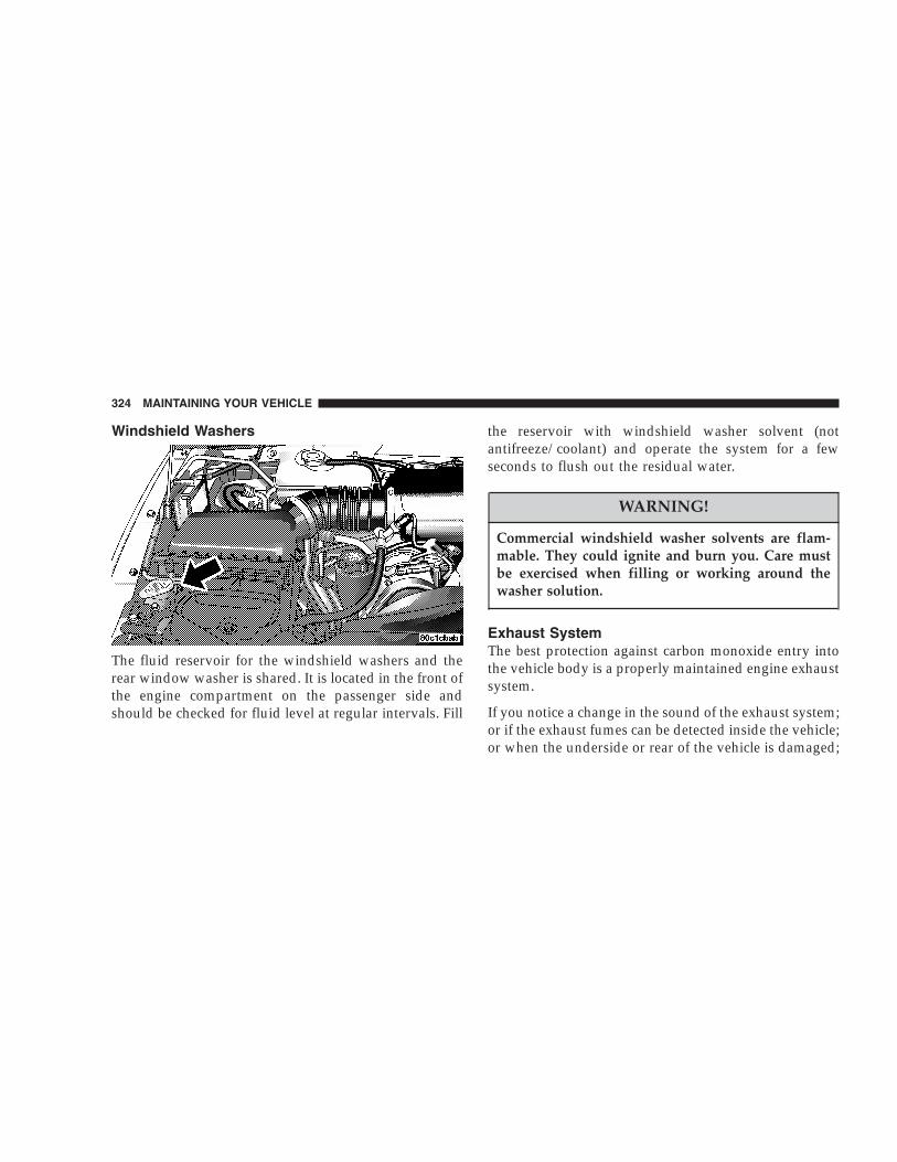
Windshield Washers
The fluid reservoir for the windshield washers and therear window washer is shared. It is located in the front ofthe engine compartment on the passenger side andshould be checked for fluid level at regular intervals. Fill
the reservoir with windshield washer solvent (notantifreeze/coolant) and operate the system for a fewseconds to flush out the residual water.
WARNING!
Commercial windshield washer solvents are flam-mable. They could ignite and burn you. Care mustbe exercised when filling or working around thewasher solution.
Exhaust SystemThe best protection against carbon monoxide entry intothe vehicle body is a properly maintained engine exhaustsystem.
If you notice a change in the sound of the exhaust system;or if the exhaust fumes can be detected inside the vehicle;or when the underside or rear of the vehicle is damaged;
324 MAINTAINING YOUR VEHICLE

have an authorized technician inspect the complete ex-haust system and adjacent body areas for broken, dam-aged, deteriorated, or mispositioned parts. Open seamsor loose connections could permit exhaust fumes to seepinto the passenger compartment. In addition, inspect theexhaust system each time the vehicle is raised for lubri-cation or oil change. Replace as required.
Cooling System
WARNING!
You or others can be badly burned by hot antifreeze/coolant or steam from your radiator. If you see orhear steam coming from under the hood, don’t openthe hood until the radiator has had time to cool.Never try to open a cooling system pressure capwhen the radiator or coolant bottle is hot.
Engine Coolant ChecksCheck antifreeze/coolant protection every 12 months(before the onset of freezing weather, where applicable).If antifreeze/coolant is dirty or rusty in appearance, thesystem should be drained, flushed and refilled with freshantifreeze/coolant. Check the front of the A/C condenser(if equipped) or radiator for any accumulation of bugs,leaves, etc. If dirty, clean by gently spraying water from agarden hose vertically down the face of the A/C con-denser (if equipped) or the radiator core.
Check the engine cooling system hoses for brittle rubber,cracking, tears, cuts, and tightness of connection at thecoolant recovery bottle and radiator. Inspect the entiresystem for leaks.
MAINTAINING YOUR VEHICLE 325
7

Cooling System — Drain, Flush, And RefillAt the intervals shown on the appropriate “MaintenanceSchedule” the system should be drained, flushed, andrefilled.
If the coolant solution is dirty or contains a considerableamount of sediment, clean and flush with a reliablecooling system cleaner (see your authorized dealer forrecommendations). Follow with a thorough rinsing toremove all deposits and chemicals. Properly dispose ofold antifreeze/coolant solution.
Selection Of Engine CoolantUse only the manufacturer’s recommended antifreeze/coolant, refer to Recommended Fluids, Lubricants, andGenuine Parts for correct antifreeze/coolant type.
CAUTION!
• Mixing of antifreeze/coolant other than the speci-fied HOAT antifreeze/coolant may result in de-creased corrosion protection and engine damage.If a non-HOAT antifreeze/coolant is introducedinto the cooling system in an emergency, it shouldbe replaced with the specified antifreeze/coolantas soon as possible.
• Do not use plain water alone or alcohol baseantifreeze/coolant products. Do not use additionalrust inhibitors or antirust products, as they maynot be compatible with the antifreeze/coolant andmay plug the radiator.
• This vehicle has not been designed for use withPropylene Glycol based antifreeze/coolant. Use ofPropylene Glycol base antifreeze/coolant is notrecommended.
326 MAINTAINING YOUR VEHICLE

Adding Engine CoolantYour vehicle has been built with an improved antifreeze/coolant that allows extended maintenance intervals. Thisantifreeze/coolant can be used up to 5 Years or 100,000miles before replacement. To prevent reducing this ex-tended maintenance period, it is important that you usethe same antifreeze/coolant throughout the life of yourvehicle. Please review these recommendations for usingHybrid Organic Additive Technology (HOAT) coolant.
When adding antifreeze/coolant, a minimum solution of50% recommended Mopar� Antifreeze/Coolant 5 Year/100,000 Mile Formula HOAT (Hybrid Organic AdditiveTechnology), or equivalent, in water should be used. Usehigher concentrations (not to exceed 70%) if temperaturesbelow -34°F (-37°C) are anticipated.
Use only high purity water such as distilled or deionizedwater when mixing the water/antifreeze (coolant) solu-tion. The use of lower quality water will reduce theamount of corrosion protection in the engine coolingsystem.
Please note that it is the owner’s responsibility to main-tain the proper level of protection against freezing ac-cording to the temperatures occurring in the area wherethe vehicle is operated.
NOTE: Mixing antifreeze/coolant types will decreasethe life of the antifreeze/coolant and will require morefrequent antifreeze/coolant changes.
Cooling System Pressure CapThe cap must be fully tightened to prevent loss ofantifreeze/coolant, and to insure that antifreeze/coolantwill return to the radiator from the coolant recoverybottle.
MAINTAINING YOUR VEHICLE 327
7

The cap should be inspected and cleaned if there is anyaccumulation of foreign material on the sealing surfaces.
WARNING!
The warning words DO NOT OPEN HOT on thecooling system pressure cap are a safety precaution.Never add antifreeze/coolant when the engine isoverheated. Do not loosen or remove the cap to coolan overheated engine. Heat causes pressure to buildup in the cooling system. To prevent scalding orinjury, do not remove the pressure cap while thesystem is hot or under pressure.
Disposal of Used Engine CoolantUsed Hybrid Organic Additive Technology (HOAT)antifreeze/coolant is a regulated substance requiringproper disposal. Check with your local authorities todetermine the disposal rules for your community. To
prevent ingestion by animals or children, do not storeHOAT antifreeze/coolant in open containers, or allow itto remain in puddles on the ground. If ingested by achild, contact a physician immediately. Clean up groundspills immediately.
Engine Coolant LevelThe coolant recovery bottle provides a quick visualmethod for determining that the antifreeze/coolant levelis adequate. With the engine idling, and warm to normaloperating temperature, the level of the antifreeze/coolantshould be between the ranges indicated on the bottle.
The radiator normally remains completely full, so there isno need to remove the radiator cap unless checking forantifreeze/coolant freeze point or replacing coolant. Ad-vise your service attendant of this. As long as the engineoperating temperature is satisfactory, the coolant bottleneed only be checked once a month.
328 MAINTAINING YOUR VEHICLE

When additional antifreeze/coolant is needed to main-tain the proper level, it should be added to the coolantrecovery bottle. Do not overfill.
Points To Remember
NOTE: When the vehicle is stopped after a few miles(kilometers) of operation, you may observe vapor comingfrom the front of the engine compartment. This is normally
a result of moisture from rain, snow, or high humidityaccumulating on the radiator and being vaporized whenthe thermostat opens, allowing hot water to enter theradiator.
If an examination of your engine compartment shows noevidence of radiator or hose leaks, the vehicle may besafely driven. The vapor will soon dissipate.
• Do not overfill the coolant recovery bottle.
• Check antifreeze/coolant freeze point in the system.
• If frequent antifreeze/coolant additions are required,or if the level in the recovery bottle does not dropwhen the engine cools, the cooling system should bepressure tested for leaks.
• Maintain engine coolant/anti-freeze concentration to50% HOAT engine coolant/anti-freeze (minimum)and distilled water for proper corrosion protection ofyour engine which contains aluminum components.
MAINTAINING YOUR VEHICLE 329
7
• Make sure that the radiator and coolant recoverybottle hoses are not kinked or obstructed.
• Keep the front of the radiator clean. Also, if yourvehicle is equipped with air conditioning, keep thefront of the condenser clean.
• Do not change the thermostat for summer or winteroperation. If replacement is ever necessary, installONLY the correct type thermostat. Other designs mayresult in unsatisfactory cooling performance, poor gasmileage, and increased emissions.
Hoses and Vacuum/Vapor HarnessesInspect surfaces of hoses and nylon tubing for evidenceof heat and mechanical damage. Hard or soft spots,brittle rubber, cracking, tears, cuts, abrasions, and exces-sive swelling indicate deterioration of the rubber.
Pay particular attention to the hoses nearest to high heatsources such as the exhaust manifold. Inspect hose rout-ing to be sure hoses do not touch any heat source ormoving component that may cause heat damage ormechanical wear.
Insure nylon tubing in these areas has not melted orcollapsed. Inspect all hose connections such as clampsand couplings to make sure they are secure and no leaksare present. Components should be replaced immedi-ately if there is any evidence of degradation that couldcause failure.
Brake SystemIn order to assure brake system performance, all brakesystem components should be inspected periodically.Refer to the appropriate “Maintenance Schedule” inSection 8 for suggested service intervals.
330 MAINTAINING YOUR VEHICLE

WARNING!
Riding the brakes can lead to brake failure andpossibly an accident. Driving with your foot restingor riding on the brake pedal can result in abnormallyhigh brake temperatures, excessive lining wear, andpossible brake damage. You wouldn’t have your fullbraking capacity in an emergency.
Brake and Power Steering System HosesWhen servicing the vehicle for scheduled maintenance,inspect surface of hoses for evidence of heat and me-chanical damage. Hard and brittle rubber, cracking, tears,cuts, abrasion, and excessive swelling suggest deteriora-tion of the rubber. Particular attention should be made toexamining those hose surfaces nearest to high heatsources, such as the exhaust manifold.
Inspect all hose clamps and couplings to make sure theyare secure and no leaks are present.
NOTE: Often fluids such as oil, power steering fluid,and brake fluid are used during assembly plant opera-tions to ease the assembly of hoses to couplings. There-fore, oil wetness at the hose-coupling area is not neces-sarily an indication of leakage. Actual dripping of hotfluid when systems are under pressure (during vehicleoperation) should be noted before hose is replaced basedon leakage.
NOTE: Inspection of brake hoses should be done when-ever the brake system is serviced and every engine oilchange.
MAINTAINING YOUR VEHICLE 331
7

WARNING!
Worn brake hoses can burst and cause brake failure.You could have an accident. If you see any signs ofcracking, scuffing, or worn spots, have the brakehoses replaced immediately.
Brake Master CylinderThe fluid level in the master cylinder should be checkedwhen performing under hood services, or immediately ifthe “Brake Warning Light” shows system failure.
Be sure to clean the top of the master cylinder area beforeremoving the cap. If necessary, add fluid to bring thefluid level up to the requirements described on the brakefluid reservoir. With disc brakes, fluid level can beexpected to fall as the brake pads wear. However, lowfluid level may be caused by a leak and a checkup may beneeded.
332 MAINTAINING YOUR VEHICLE

Use only manufacturer’s recommended brake fluid, referto Recommended Fluids, Lubricants, and Genuine Partsfor correct fluid type.
WARNING!
Use of a brake fluid that may have a lower initialboiling point or unidentified as to specification, mayresult in sudden brake failure during hard pro-longed braking. You could have an accident.
WARNING!
Overfilling the brake fluid reservoir can result inspilling brake fluid on hot engine parts and thebrake fluid catching fire.
Use only brake fluid that has been in a tightly closedcontainer to avoid contamination from foreign matter. Donot allow petroleum base fluid to contaminate the brakefluid as seal damage will result.
Automatic Transmission
Selection of LubricantIt is important that the proper lubricant is used in thetransmission to assure optimum transmission perfor-mance. Use only manufacturer’s recommended transmis-sion fluid, refer to Recommended Fluids, Lubricants, andGenuine Parts for correct fluid type. It is important thatthe transmission fluid be maintained at the prescribedlevel using the recommended fluid.
MAINTAINING YOUR VEHICLE 333
7

CAUTION!
Using a transmission fluid other than the manufac-turer’s recommended fluid may cause deteriorationin transmission shift quality and/or torque convertershudder. Using a transmission fluid other than themanufacturer’s recommended fluid will result inmore frequent fluid and filter changes. Refer toRecommended Fluids, Lubricants, and GenuineParts for correct fluid type.
Fluid Level Check – 3.7L Gasoline Engine (42RLE)and 2.8L Diesel Engine (545RFE)This fluid level should be checked when the engine isfully warmed up and the fluid in the transmission isheated to its normal operating temperature. Operation ofthe transmission with an improper fluid level will greatlyreduce the life of the transmission and of the fluid.
To check the automatic transmission fluid level properly,the following procedure must be used:
1. The vehicle must be on level ground.
2. The engine should be running at curb idle speed for aminimum of 60 seconds.
3. Fully apply parking brake.
4. Apply the brakes and shift the transmission into P(Park).
5. The fluid MUST be checked with the transmission inP (Park) to be sure that the fluid level is accurate.
6. Wipe the dipstick clean and reinsert until seated.Remove dipstick and note reading.
At normal operating temperature (approximately 180° F(82° C), the fluid level is correct if it is in the HOT region
334 MAINTAINING YOUR VEHICLE

(cross-hatched area) on the oil level indicator. The fluidlevel indicator should be in the COLD region at 70° F (21°C) fluid temperature.
If the fluid level is low, add sufficient fluid to bring to theproper level. Refer to Recommended Fluids, Lubricantsand Genuine Parts for correct fluid type.
Fluid is added through the dipstick tube.
NOTE: To prevent dirt and water from entering thetransmission after checking or replenishing fluid, makecertain that the dipstick cap is properly reseated.
Special AdditivesThe manufacturer recommends against the addition ofany additives to the transmission. Exception to thispolicy is the use of special dyes to aid in detecting fluidleaks.
Hydraulic Clutch Fluid — Manual TransmissionThe clutch hydraulic system is a sealed maintenance freesystem. In the event of leakage or other malfunction, thesystem must be replaced.
Manual Transmission
Selection of LubricantUse only manufacturer’s recommended manual trans-mission fluid, refer to Recommended Fluids, Lubricants,and Genuine Parts for correct fluid type.
Fluid Level CheckCheck the fluid level by removing the fill plug. The fluidlevel should be between the bottom of the fill hole and apoint not more than 3/16” (4.76 mm) below the bottom ofthe hole.
Add fluid, if necessary, to maintain the proper level.
MAINTAINING YOUR VEHICLE 335
7

Frequency of Fluid ChangeUnder normal operating conditions, the fluid installed atthe factory will give satisfactory lubrication for the life ofthe vehicle. Fluid changes are not necessary unless thelubricant has become contaminated with water. If con-taminated with water, the fluid should be changed im-mediately.
Transfer Case
Fluid Level CheckInspect the transfer case for fluid leaks. If a fluid leak isevident, the transfer case fluid level can be checked byremoving the fill plug (B) located at the back of thetransfer case.
The fluid level should be to the bottom edge of the fillhole (A) when the vehicle is in a level position.
Adding FluidOnly at filler hole until fluid runs out of the hole, whenthe vehicle is in a level position.
DrainFirst remove fill plug (B), then drain plug (C). Recom-mended tightening torque for drain and fill plugs is15–25 ft. lbs. (20–34 N·m).
336 MAINTAINING YOUR VEHICLE

CAUTION!
When installing plugs, do not overtighten. You coulddamage them and cause them to leak.
Selection of LubricantUse only manufacturer’s recommended fluid, refer toRecommended Fluids, Lubricants, and Genuine Parts forcorrect fluid type.
Front/Rear Axle FluidThe front axle has a threaded “fill plug” on the coverplate, and a threaded “drain plug” on the bottom side ofthe carrier.
Fluid Level CheckLubricant should be 1/2� (1 cm) below the oil fill hole.
Adding FluidAdd lubricant only at the fill hole and only to the levelspecified above.
Selection of LubricantUse only manufacturer’s recommended fluid, refer toRecommended Fluids, Lubricants, and Genuine Parts forcorrect fluid type.
Appearance Care And Protection From Corrosion
Protection Of Body And Paint From CorrosionVehicle body care requirements vary according to geo-graphic locations and usage. Chemicals that make roadspassable in snow and ice, and those that are sprayed ontrees and road surfaces during other seasons, are highlycorrosive to the metal in your vehicle. Outside parking,which exposes your vehicle to airborne contaminants,road surfaces on which the vehicle is operated, extreme
MAINTAINING YOUR VEHICLE 337
7
hot or cold weather and other extreme conditions willhave an adverse effect on paint, metal trim, and under-body protection.
The following maintenance recommendations will enableyou to obtain maximum benefit from the corrosionresistance built into your vehicle.
What Causes Corrosion?Corrosion is the result of deterioration or removal ofpaint and protective coatings from your vehicle.
The most common causes are:
• Road salt, dirt and moisture accumulation.
• Stone and gravel impact.
• Insects, tree sap and tar.
• Salt in the air near sea-coast localities.
• Atmospheric fallout/industrial pollutants.
Washing
• Wash your vehicle regularly. Always wash your ve-hicle in the shade using a mild car wash soap and rinsethe panels completely with clear water.
• If insects, tar, or other similar deposits have accumu-lated on your vehicle, wash it as soon as possible.
• Use Mopar� Auto Polish to remove road film andstains and to polish your vehicle. Take care never toscratch the paint.
• Avoid using abrasive compounds and power buffingthat may diminish the gloss or thin out the paintfinish.
338 MAINTAINING YOUR VEHICLE

CAUTION!
Do not use abrasive or strong cleaning materialssuch as steel wool or scouring powder, which willscratch metal and painted surfaces.
Special Care
• If you drive on salted or dusty roads or if you drivenear the ocean, hose off the undercarriage at least oncea month.
• It is important that the drain holes in the lower edgesof the doors, rocker panels and tailgate must be keptclear and open.
• If you detect any stone chips or scratches in the paint,touch them up immediately. The cost of such repairs isconsidered the responsibility of the owner.
• If your vehicle is damaged due to an accident orsimilar cause which destroys the paint and protectivecoating have your vehicle repaired as soon as possible.The cost of such repairs is considered the responsibil-ity of the owner.
• All wheels and wheel trim, especially aluminum andchrome plated wheels should be cleaned regularlywith mild soap and water to prevent corrosion. Toremove heavy soil, select a non-abrasive, non-acidiccleaner. Do not use scouring pads, steel wool, a bristlebrush, or metal polishes. Only Mopar� Cleaners arerecommended. Do not use oven cleaner. Avoid auto-matic car washes that use acidic solutions or harshbrushes that may damage the wheel’s protective fin-ish.
• If you carry special cargo such as chemicals, fertilizers,de-icer salt, etc., be sure that such materials are wellpackaged and sealed.
MAINTAINING YOUR VEHICLE 339
7

• If a lot of driving is done on gravel roads, considermud or stone shields behind each wheel.
• Use Mopar� Touch Up Paint on scratches or chips assoon as possible. Your authorized dealer has touch uppaint to match the color of your vehicle.
Interior CareUse Mopar� Fabric Cleaner to clean fabric upholsteryand carpeting.
Use Mopar� Vinyl Cleaner to clean vinyl or leatherupholstery.
Mopar� Vinyl Cleaner is specifically recommended forinterior vinyl trim.
Leather Seat Care & CleaningLeather is best preserved by regular cleaning with adamp soft cloth. Small particles of dirt can act as anabrasive and damage the leather surface and should beremoved promptly with a damp cloth. Stubborn soils can
be removed easily with a soft cloth and Mopar� TotalClean. Care should be taken to avoid soaking the leatherwith any liquid. Please do not use polishes, oils, cleaningfluids, solvents, detergents, or ammonia based cleanersto clean the leather. Application of a leather conditioner isnot required to maintain the original condition.
WARNING!
Do not use volatile solvents for cleaning purposes.Many are potentially flammable, and if used inclosed areas they may cause respiratory harm.
Glass SurfacesAll glass surfaces should be cleaned on a regular basiswith any commercial household-type glass cleaner.Never use an abrasive type cleaner. Use caution when
340 MAINTAINING YOUR VEHICLE

cleaning inside rear windows equipped with electricdefrosters. Do not use scrapers or other sharp instru-ments which may scratch the elements.
When cleaning the rear view mirror, spray cleaner on thetowel or rag that you are using. Do not spray cleanerdirectly on the mirror.
CarpetVacuum your carpet regularly to prevent a soil build-up.Shampoo soiled carpet with a reliable upholstery cleaner,using a natural sponge or soft bristle brush. After carpetdries, vacuum it thoroughly.
Seat Belt MaintenanceDo not bleach, dye or clean the belts with chemicalsolvents or abrasive cleaners. This will weaken the fabric.Sun damage will also weaken the fabric.
If the belts need cleaning, use a mild soap solution orlukewarm water. Do not remove the belts from thevehicle to wash them.
Replace the belts if they appear frayed or worn or if thebuckles do not work properly.
Maintenance After Off-Pavement DrivingAfter extended operation in mud, sand or water, orsimilar dirty conditions, have your brake drums, brakelinings, and axle joints inspected and cleaned as soon aspossible. This will prevent any abrasive material fromcausing excessive wear or unpredictable braking action.
Following off-pavement usage, completely inspect theunderbody of your vehicle. Check tires, body structure,steering, suspension and exhaust system for damage.Check threaded fasteners for looseness, particularly onthe chassis, drivetrain components, steering and suspen-sion. Retighten, if required, to torque values specified inthe Service Manual. Also check for accumulations of
MAINTAINING YOUR VEHICLE 341
7

vegetation or brush that could become a fire hazard, orconceal damage to fuel lines, brake hoses, axle pinionseals, and propeller shafts.
CAUTION!
Under frequent heavy-duty driving conditions,change all lubricants and lubricate body compo-nents, all driveline joints and steering linkage moreoften than in normal service to prevent excessivewear.
FUSE PANEL
Interior FusesThe fuse panel is on the left side of the instrument panel.A label is attached to the fuse panel cover to identify eachfuse for ease of replacement.
Fuse Panel
342 MAINTAINING YOUR VEHICLE

Cavity Fuse Description1 15 Amp Blue Horn Relay, Power Sunroof
Relay, Power Window Relay2 10 Amp Red Rear Fog Lights (Export
Only)3 20 Amp Yel-
lowCigar Lighter
4 10 Amp Red Headlight Low Beam Right5 10 Amp Red Headlight Low Beam Left6 20 Amp Yel-
lowBody Control Module/PowerDoor Locks
7 10 Amp Red Left Park Light/Left TailLamp/License Plate Lamp
8 Spare9 10 Amp Red Right Park Light/RightTail
Lamp/License Plate Lamp/Cluster
10 Spare
Cavity Fuse Description11 15 Amp Blue Flasher12 15 Amp Blue Stop Lights13 10 Amp Red Body Control Module/
CMTC/Cluster/Pass. AirbagOn,Off Indicator, Auto Day-light Mirror/Light BarSwitch (Renegade Only)
14 10 Amp Red PDC Fuel Pump/AC Clutch,Starter Relay/EngineController/TransmissionController (Diesel Only)
15 Spare16 20 Amp Yel-
lowPower Outlet (Rear)
17 15 Amp Blue Rear Wiper18 20 Amp Yel-
lowRadio Choke & Relay
MAINTAINING YOUR VEHICLE 343
7

Cavity Fuse Description19 20 Amp Yel-
lowFrt Fog Lights/Trailer TowStop and Turn Lights
20 Spare21 10 Amp Red Radio22 20 Amp Yel-
lowPower Sunroof Relay/Antenna Module (ExportOnly)
23 Spare24 10 Amp Red PDC Blower Motor25 10 Amp Red Heated Seat Switches/HVAC
Control Head/Trailer TowBattery Charge
26 10 Amp Red Headlight High Beam Right27 10 Amp Red Headlight High Beam Left28 Spare29 10 Amp Red Heated Mirrors/Rear Win-
dow Defroster Indicator
Cavity Fuse Description30 15 Amp Blue Heated Seat Module31 Spare32 10 Amp Red Wiper Switch/Front and
Rear Wipers33 10 Amp Red SKIM Module/Data Link
Connector34 15 Amp Blue Body Control Module/
Cluster/Interior Lights,Hands Free Module/Radio/CMTC/ITM Module & Siren(Export Only)
35 Spare36 10 Amp Red Airbag Control Module/
Occupation ClassificationModule (Right Front Seat)
37 10 Amp Red Airbag Control Module
344 MAINTAINING YOUR VEHICLE

Cavity Fuse Description38 10 Amp Red ABS Controller/Shifter As-
sembly39 10 Amp Red Hazard Flasher (Turn
Signals)/Backup LampSwitch (Manual TransmissionOnly)/Transmission RangeSwitch (Automatic Transmis-sion Only)
Underhood Fuses (Power Distribution Center)Your vehicle is equipped with an electrical power distri-bution center located in the engine compartment near thebattery. This power center houses plug-in “Cartridge”fuses which replace in-line fusible links. The powercenter also contains “Mini” fuses and plug-in full andmicro ISO relays. A label inside the latching cover of thecenter identifies each component for ease of replacement,if necessary. “Cartridge” fuses and relays can be obtainedfrom your authorized dealer.
Power Distribution Center (Gasoline Engines)
Cavity Fuse DescriptionF1 40 Amp
GreenBlower Motor
F2 40 AmpGreen
Radiator Fan
Power Distribution Center
MAINTAINING YOUR VEHICLE 345
7

Cavity Fuse DescriptionF3 50 Amp Red JB PowerF4 40 Amp
GreenABS Pump
F5 20 Amp Yel-low
NGC Trans
F6 30 Amp Pink ASDF7 50 Amp Red JB PowerF8 40 Amp
GreenIgn/Start
F9 50 Amp Red JB PowerF10 30 Amp Pink Trailer TowF11 OpenF12 30 Amp Pink Light BarF13 40 Amp
GreenWindows
F14 40 AmpGreen
Ignition Switch
Cavity Fuse DescriptionF15 50 Amp Red JB PowerF16 OpenF17 OpenF18 OpenF19 30 Amp Pink Rear Window Defogger
(HBL)F20 OpenF21 20 Amp Yel-
lowA/C Clutch
F22 OpenF23 OpenF24 20 Amp Yel-
lowFuel Pump
F25 20 Amp Yel-low
ABS Valves
F26 25 AmpNatural
Injectors
346 MAINTAINING YOUR VEHICLE

Cavity Fuse DescriptionF27 OpenF28 15 Amp Blue StarterR29 Half ISO Re-
layFuel Pump
R30 Half ISO Re-lay
Starter
R31 Half ISO Re-lay
Wiper On/Off
R32 Half ISO Re-lay
Wiper Hi/Lo
R33 Full ISO Re-lay
H. Blower
R34 Full ISO Re-lay
Rad. Fan Hi
R35 Half ISO Re-lay
A/C Clutch
R36 Open
Cavity Fuse DescriptionR37 Half ISO Re-
layNGC Trans
R38 OpenR39 Full ISO Re-
layASD
R40 Full ISO Re-lay
Rad. Fan Lo
Power Distribution Center (Diesel Engines)
Cavity Fuse DescriptionF1 40 Amp
GreenBlower Motor
F2 40 AmpGreen
Radiator Fan
F3 50 Amp Red JB PowerF4 40 Amp
GreenABS Pump
MAINTAINING YOUR VEHICLE 347
7
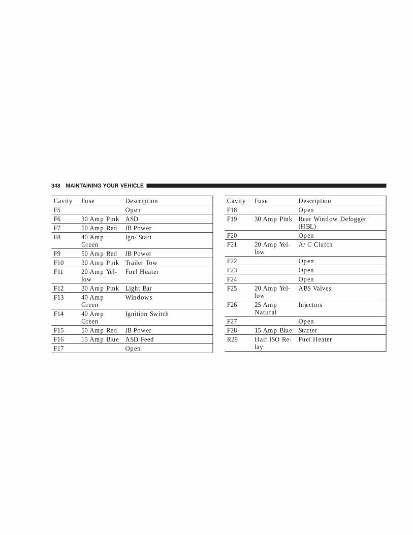
Cavity Fuse DescriptionF5 OpenF6 30 Amp Pink ASDF7 50 Amp Red JB PowerF8 40 Amp
GreenIgn/Start
F9 50 Amp Red JB PowerF10 30 Amp Pink Trailer TowF11 20 Amp Yel-
lowFuel Heater
F12 30 Amp Pink Light BarF13 40 Amp
GreenWindows
F14 40 AmpGreen
Ignition Switch
F15 50 Amp Red JB PowerF16 15 Amp Blue ASD FeedF17 Open
Cavity Fuse DescriptionF18 OpenF19 30 Amp Pink Rear Window Defogger
(HBL)F20 OpenF21 20 Amp Yel-
lowA/C Clutch
F22 OpenF23 OpenF24 OpenF25 20 Amp Yel-
lowABS Valves
F26 25 AmpNatural
Injectors
F27 OpenF28 15 Amp Blue StarterR29 Half ISO Re-
layFuel Heater
348 MAINTAINING YOUR VEHICLE

Cavity Fuse DescriptionR30 Half ISO Re-
layStarter
R31 Half ISO Re-lay
Wiper On/Off
R32 Half ISO Re-lay
Wiper Hi/Lo
R33 Full ISO Re-lay
H. Blower
R34 Full ISO Re-lay
Rad. Fan Hi
R35 Half ISO Re-lay
A/C Clutch
R36 Half ISO Re-lay
Viscous Heat
R37 OpenR38 Open
Cavity Fuse DescriptionR39 Full ISO Re-
layASD
R40 Full ISO Re-lay
Rad. Fan Lo
VEHICLE STORAGEIf you are leaving your vehicle dormant for more than 21days you may want to take steps to protect your battery.You may:
• Remove Cartridge fuse #15 in the Power DistributionCenter labeled Ignition-Off Draw (IOD).
• Store the removed IOD fuse in the Power DistributionCenter location #11 labeled “IOD Storage.”
• Or, disconnect the negative cable from the battery.
• Anytime you store your vehicle, or keep it out ofservice (i.e. vacation) for two weeks or more, run the
MAINTAINING YOUR VEHICLE 349
7

air conditioning system at idle for about five minutesin the fresh air and high blower setting. This willinsure adequate system lubrication to minimize thepossibility of compressor damage when the system isstarted again.
REPLACEMENT BULBS
Interior Lights Bulb TypeA/C Heater . . . . . . . . . . . . . . . . . . . . Not ServiceableAshtray Receiver Light . . . . . . . . . . . . . . . . . . . . 161Climate Control (Manual A/C). . . . . . . . . . . . . . . . 74Front Reading . . . . . . . . . . . . . . . . . . . . . . . . . . . 192Rear Cargo Light . . . . . . . . . . . . . . . . . . . . . . . 214–2Lighted Vanity Mirror * . . . . . . . . . . . . . . P/N 6501966Underpanel Courtesy Lights . . . . . . . . . . . . . . . . . 906Instrument Cluster (General Illumination) . . . . . . . 103Telltale/Hazard Light . . . . . . . . . . . . . . . . . . . . . . 74
* Available only from authorized dealers.
Exterior Lights Bulb TypeBackup Lights . . . . . . . . . . . . . . . . . . . . 3157 P27/7WCenter High-Mounted Stoplight . . . . . . . . . 921/W16WFog Lights (Sport/Limited Only) . . . . . . . . . . . . . 9145Fog Lights (Renegade) . . . . . . . . . . . . . . . . . . . . . H3Front Park/Turn Lights . . . . . . . . . . . . . 3157 P27/7WFront Side Marker . . . . . . . . . . . . . . . . . . . . . . . . 168Headlights . . . . . . . . . . . . . . . . . . . . . . . . . . 9007QLRear License Plate Light . . . . . . . . . . . . . . . . . . . . 168Rear Stop/Tail Lights . . . . . . . . . . . . . . . 3157 P27/7WRear Turn Signal Lights (2) . . . . . . . . . 3757 APY27/7W
NOTE: Numbers refer to commercial bulb types thatcan be purchased from your authorized dealer.
If a bulb needs to be replaced, visit your authorizeddealer.
350 MAINTAINING YOUR VEHICLE

BULB REPLACEMENT
Head Light
1. Open the hood.
2. Reach behind the headlamp unit in the engine com-partment to access the headlamp bulb lock ring.
3. Firmly grasp the lock ring on the back of the headlampunit housing.
4. Rotate the lock ring on the back of the headlamphousing counter-clockwise to unlock it.
CAUTION!
Do not touch the new bulb with your fingers. Oilcontamination will severely shorten bulb life. If thebulb comes in contact with any oily surface, cleanthe bulb with rubbing alcohol.
5. Disconnect the electrical connector and replace thebulb.
MAINTAINING YOUR VEHICLE 351
7

Front Turn Signal
1. Remove the screw from the turn signal/park lampunit.
2. Pull the inboard side of the lamp away enough todisengage the tab that secures the outboard side of thelamp from the slot in the front bumper fascia.
3. Rotate the bulb socket counter-clockwise to unlock it.
CAUTION!
Do not touch the new bulb with your fingers. Oilcontamination will severely shorten bulb life. If thebulb comes in contact with any oily surface, cleanthe bulb with rubbing alcohol.
4. Disconnect the electrical connector and replace thebulb.
352 MAINTAINING YOUR VEHICLE

Front Fog Light (Front Fascia Mounted)
1. Remove the three screws from the backside of thelamp housing.
2. Pull the bezel and lens away from the lamp housingfar enough to access and disconnect the wiring connectorfrom the bulb pigtail wire.
3. Pinch together the two hooked ends of the bulbretainer clip and disengage them from the slots in themounting flange on the back of the lens reflector.
4. Pivot the retainer clip up off of the bulb flange and outof the way.
CAUTION!
Do not touch the new bulb with your fingers. Oilcontamination will severely shorten bulb life. If thebulb comes in contact with any oily surface, cleanthe bulb with rubbing alcohol.
5. Pull the bulb straight out of the mounting flange andreplace the bulb.
MAINTAINING YOUR VEHICLE 353
7

Light Bar
1. Remove the screws from the light bar cover.
2. Remove the light bar cover.
3. Disconnect wiring harness from bulb socket.
4. Rotate the socket on the back of the lamp housingcounter-clockwise to unlock it.
CAUTION!
Do not touch the new bulb with your fingers. Oilcontamination will severely shorten bulb life. If thebulb comes in contact with any oily surface, cleanthe bulb with rubbing alcohol.
5. Replace the bulb.
354 MAINTAINING YOUR VEHICLE

Rear Tail, Stop, Turn Signal, and Back-Up Lights1. Open the swing gate.2. Remove the two Torx fasteners.
3. Remove rear lamp assembly.4. Rotate the socket on the back of the lamp housingcounter-clockwise to unlock it.5. Replace the bulb.
Center High Mounted Stop Light (CHMSL)1. Remove the two screws securing the CHMSL.
2. Twist the bulb socket to remove from the CHMSLhousing.3. Pull the bulb out of the socket.
4. Replace the bulb, reinstall the socket and reattach theCHMSL.
MAINTAINING YOUR VEHICLE 355
7

FLUID CAPACITIES
U.S. MetricFuel (Approximate) 20.5 Gallons 78 LitersEngine Oil with Filter2.4/3.7 Liter Engines (SAE 5W-30, API Certified Engine Oil) 5 Qts 4.7 Liters
2.8 Liter Diesel Engine (SAE 0W-40 Mobil 1� Synthetic, APICertified Engine Oil)
6.4 Qts 6.1 Liters
Cooling System *2.4 Liter Engine (Mopar� Antifreeze/Coolant 5 Year/100,000
Mile Formula)10 Qts 9.5 Liters
3.7 Liter Engine (Mopar� Antifreeze/Coolant 5 Year/100,000Mile Formula)
14 Qts 13.2 Liters
2.8 Liter Diesel Engine (Mopar� Antifreeze/Coolant 5 Year/100,000 Mile Formula)
11.8 Qts 12.5 Liters
* Includes heater and coolant recovery bottle filled to MAX level.
356 MAINTAINING YOUR VEHICLE

RECOMMENDED FLUIDS, LUBRICANTS AND GENUINE PARTSEngine
Component Fluid, Lubricant, or Genuine PartEngine Coolant Mopar� Antifreeze/Coolant 5 Year/100,000 Mile Formula HOAT (Hybrid Or-
ganic Additive Technology)Engine Oil (2.4L and 3.7L Engines) Use API Certified SAE 5W-30 Engine Oil, meeting the requirements of
DaimlerChrysler Material Standard MS-6395.Engine Oil (2.8L Diesel Engines) Use API Certified SAE 0W-40 Mobil 1� Synthetic Engine Oil that meets API
Categories SL/CF, and the requirements of DaimlerChrysler Material Stan-dard MS-10725. If SAE 0W-40 is not available, SAE 5W-40 Mobil 1� SyntheticEngine Oil is acceptable.
Oil Filter (2.4L Engine) Mopar� Oil Filter (P/N 4105409 or 4105409AB)Oil Filter (3.7L Engine) Mopar� Oil Filter (P/N 4781452AA or 4781452BB)Oil Filter (2.8L Diesel Engine) Mopar� Oil Filter (P/N 05072720AA)Spark Plugs Refer to the Vehicle Emission Control Information label in the engine com-
partment.Fuel Selection (Gasoline EnginesOnly)
87 Octane (89 Octane should be used for trailer towing purposes - 3.7LOnly).
MAINTAINING YOUR VEHICLE 357
7

Chassis
Component Fluid, Lubricant, or Genuine PartAutomatic Transmission Mopar� ATF+4 Automatic Transmission FluidManual Transmission Mopar� Manual Transmission Lubricant or equivalent (meeting the re-
quirements of DaimlerChrysler Material Standard MS-9224)Transfer Case Mopar� ATF+4 Automatic Transmission FluidAxle Differential (Front) Mopar� Gear & Axle Lubricant (SAE 80W-90) or equivalent.Axle Differential (Rear) Mopar� Synthetic Gear Lubricant (SAE 75W-90) or equivalent. For trailer
towing, the lubricant should be replaced with Mopar� Synthetic Gear &Axle Lubricant (SAE 75W-140) or equivalent. Models equipped with Trac-Lok™ require a limited-slip additive.
Brake Master Cylinder Mopar� DOT 3 Brake Fluid, SAE J1703 should be used. If DOT 3, SAEJ1703 brake fluid is not available, then DOT 4 is acceptable. Use only rec-ommended brake fluids.
Power Steering Reservoir Mopar� ATF+4 Automatic Transmission Fluid
358 MAINTAINING YOUR VEHICLE

MAINTENANCE SCHEDULES
CONTENTS
� Emission Control System Maintenance . . . . . . . . 360
� Maintenance Schedules — Gasoline Engines . . . . 360
▫ Schedule “B” — Gasoline Engines . . . . . . . . . 363
▫ Schedule “A” — Gasoline Engines . . . . . . . . . 373
� Maintenance Schedules — Diesel Engines . . . . . 378
▫ Schedule “B” — Diesel Engines . . . . . . . . . . . 380
▫ Schedule “A” — Diesel Engines . . . . . . . . . . . 385
8
MAINTENANCE
SCHEDULES

EMISSION CONTROL SYSTEM MAINTENANCEThe “Scheduled” maintenance services, listed in boldtype must be done at the times or mileages specified toassure the continued proper functioning of the emissioncontrol system. These, and all other maintenance servicesincluded in this manual, should be done to provide bestvehicle performance and reliability. More frequent main-tenance may be needed for vehicles in severe operatingconditions such as dusty areas and very short tripdriving.
Inspection and service also should be done any time amalfunction is suspected.
NOTE: Maintenance, replacement, or repair of the emis-sion control devices and systems on your vehicle may beperformed by any automotive repair establishment orindividual using any automotive part which has beencertified pursuant to U.S. EPA or, in the State of Califor-nia, California Air Resources Board regulations.
MAINTENANCE SCHEDULES — GASOLINEENGINESThere are two maintenance schedules that show therequired service for your vehicle.
First is Schedule �B�. It is for vehicles that are operatedunder the conditions that are listed below and at thebeginning of the schedule.
• Day or night temperatures are below 32°F (0°C).
• Stop and go driving.
• Extensive engine idling.
• Driving in dusty conditions.
• Short trips of less than 10 miles (16.2 km).
• More than 50% of your driving is at sustained highspeeds during hot weather, above 90°F (32°C).
• Trailer towing.
360 MAINTENANCE SCHEDULES
8
MAINTENANCE
SCHEDULES

• Taxi, police, or delivery service (commercial service).
• Off-road or desert driving.
• If equipped for and operated with E-85 (ethanol) fuel.
NOTE: If ANY of these apply to you then change yourengine oil every 3,000 miles (5 000 km) or 3 months,whichever comes first and follow “Schedule B” of the“Maintenance Schedules” section of this manual.
NOTE: If ANY of these apply to you then flush andreplace your engine coolant/anti-freeze every 102,000miles (163 000 km) or 60 months, whichever comes first,and follow “Schedule B” of the “Maintenance Schedules”section of this manual.
NOTE: Most vehicles are operated under the conditionslisted for Schedule “B.”
Second is Schedule “A”. It is for vehicles that are notoperated under any of the conditions listed under Sched-ule “B.”
Use the schedule that best describes your driving condi-tions. Where time and mileage are listed, follow theinterval that occurs first.
CAUTION!
Failure to perform the required maintenance itemsmay result in damage to the vehicle.
MAINTENANCE SCHEDULES 361
8
MAINTENANCE
SCHEDULES

At Each Stop for Fuel
• Check the engine oil level about 5 minutes after a fullywarmed engine is shut off. Checking the oil level whilethe vehicle is on level ground will improve the accu-racy of the oil level reading. Add oil only when thelevel is at or below the ADD or MIN mark.
• Check the windshield washer solvent, add as required.
Once a Month
• Check the tire pressure and look for unusual wear ordamage.
• Inspect the battery, and clean and tighten the terminalsas required.
• Check the fluid levels of the engine coolant/anti-freeze reservoir, brake master cylinder, and transmis-sion, and add as needed.
• Check all lights and all other electrical items for correctoperation.
At Each Oil Change
• Change the engine oil filter.
• Inspect the exhaust system.
• Inspect brake hoses.
• Check the engine coolant/anti-freeze level, hoses, andclamps.
• Inspect manual transmission fluid level, and for leaks(if equipped).
• After completion of off-road operation, the undersideof the vehicle should be thoroughly inspected. Exam-ine threaded fasteners for looseness.
362 MAINTENANCE SCHEDULES
8
MAINTENANCE
SCHEDULES

Schedule “B” — Gasoline EnginesFollow schedule “B” if you usually operate your vehicleunder one or more of the following conditions.
• Day or night temperatures are below 32°F (0°C).
• Stop and go driving.
• Extensive engine idling.
• Driving in dusty conditions.
• Short trips of less than 10 miles (16.2 km).
• More than 50% of your driving is at sustained highspeeds during hot weather, above 90°F (32°C).
• Trailer towing.
• Taxi, police, or delivery service (commercial service).
• Off-road or desert driving.
• If equipped for and operated with E-85 (ethanol) fuel.
NOTE: If ANY of these apply to you then change yourengine oil every 3,000 miles (5 000 km) or 3 months,whichever comes first and follow “Schedule B” of the“Maintenance Schedules” section of this manual.
NOTE: If ANY of these apply to you then flush andreplace your engine coolant/anti-freeze every 102,000miles (163 000 km) or 60 months, whichever comes first,and follow “Schedule B” of the “Maintenance Schedules”section of this manual.
SCHEDULE “B” — GASOLINE ENGINES 363
8
MAINTENANCE
SCHEDULES

Miles 3,000 6,000 9,000 12,000 15,000(Kilometers) (5 000) (10 000) (14 000) (19 000) (24 000)Change the engine oil and engine oil filter, if notreplaced at 3 months.
X X X X X
Rotate the tires. X XInspect the engine air filter element, replace ifnecessary.
X
Inspect the brake linings. XDrain and refill the front and rear axle fluid‡ X
364 SCHEDULE “B” — GASOLINE ENGINES
8
MAINTENANCE
SCHEDULES

Miles 18,000 21,000 24,000 27,000 30,000(Kilometers) (29 000) (34 000) (38 000) (43 000) (48 000)Change the engine oil and engine oil filter, if notreplaced at 3 months.
X X X X X
Rotate the tires. X X XInspect the engine air filter element, replace ifnecessary.
X
Replace the spark plugs. XInspect and replace the PCV valve, if necessary. XInspect the brake linings. XDrain and refill the front and rear axle fluid‡ XInspect the transfer case fluid, add if necessary. X
SCHEDULE “B” — GASOLINE ENGINES 365
8
MAINTENANCE
SCHEDULES

Miles 33,000 36,000 39,000 42,000 45,000(Kilometers) (53 000) (58 000) (62 000) (67 000) (72 000)Change the engine oil and engine oil filter, if notreplaced at 3 months.
X X X X X
Rotate the tires. X XInspect the engine air filter element, replace ifnecessary.
X
Inspect the brake linings. XDrain and refill the front and rear axle fluid‡ XInspect the drive belt and replace as needed. X
366 SCHEDULE “B” — GASOLINE ENGINES
8
MAINTENANCE
SCHEDULES

Miles 48,000 51,000 54,000 57,000 60,000(Kilometers) (77 000) (82 000) (86 000) (91 000) (96 000)Change the engine oil and engine oil filter, if not replaced at3 months.
X X X X X
Rotate the tires. X X XInspect the engine air filter element, replace if necessary. XReplace the spark plugs. XInspect and replace the PCV valve, if necessary. XReplace the ignition cables (2.4L Only). XInspect the brake linings. X XDrain and refill the front and rear axle fluid‡ X XDrain and refill the automatic transmission fluid, and replacemain sump filter.†
X
Inspect the drive belt and replace as needed. Not required ifbelt was previously
X
Drain and refill the transfer case fluid. XFlush and replace the engine coolant/anti-freeze at 60months, if not done at 102,000 miles (163 000 km).
X
SCHEDULE “B” — GASOLINE ENGINES 367
8
MAINTENANCE
SCHEDULES

Miles 63,000 66,000 69,000 72,000 75,000(Kilometers) (101 000) (106 000) (110 000) (115 000) (120 000)Change the engine oil and engine oil filter, if notreplaced at 3 months.
X X X X X
Rotate the tires. X XInspect the engine air filter element, replace ifnecessary.
X
Inspect the brake linings. XDrain and refill the front and rear axle fluid‡ XInspect the drive belt and replace as needed. Notrequired if belt was previously replaced.
X
368 SCHEDULE “B” — GASOLINE ENGINES
8
MAINTENANCE
SCHEDULES
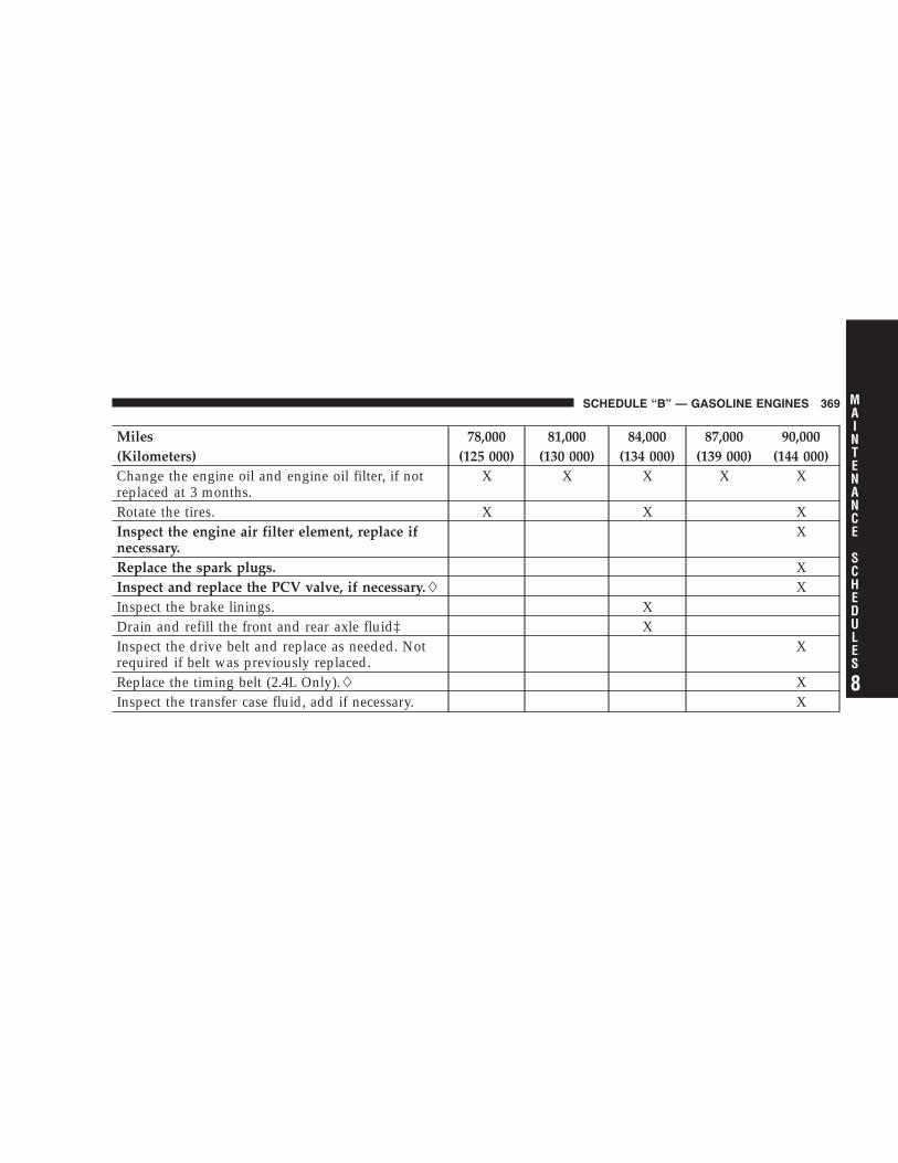
Miles 78,000 81,000 84,000 87,000 90,000(Kilometers) (125 000) (130 000) (134 000) (139 000) (144 000)Change the engine oil and engine oil filter, if notreplaced at 3 months.
X X X X X
Rotate the tires. X X XInspect the engine air filter element, replace ifnecessary.
X
Replace the spark plugs. XInspect and replace the PCV valve, if necessary. XInspect the brake linings. XDrain and refill the front and rear axle fluid‡ XInspect the drive belt and replace as needed. Notrequired if belt was previously replaced.
X
Replace the timing belt (2.4L Only). XInspect the transfer case fluid, add if necessary. X
SCHEDULE “B” — GASOLINE ENGINES 369
8
MAINTENANCE
SCHEDULES

Miles 93,000 96,000 99,000 102,000 105,000(Kilometers) (149 000) (154 000) (158 000) (163 000) (168 000)Change the engine oil and engine oil filter, if notreplaced at 3 months.
X X X X X
Rotate the tires. X XInspect the engine air filter element, replace ifnecessary.
X
Inspect the brake linings. XDrain and refill the front and rear axle fluid‡ XInspect the drive belt and replace as needed. Notrequired if belt was previously replaced.
X
Flush and replace the engine coolant/anti-freeze, ifnot done at 60 months.
X
370 SCHEDULE “B” — GASOLINE ENGINES
8
MAINTENANCE
SCHEDULES

Miles 108,000 111,000 114,000 117,000 120,000(Kilometers) (173 000) (178 000) (182 000) (187 000) (192 000)Change the engine oil and engine oil filter, if not replaced at3 months.
X X X X X
Rotate the tires. X X XInspect the engine air filter element, replace if necessary. XReplace the spark plugs. XInspect and replace the PCV valve, if necessary. XReplace the ignition cables (2.4L Only). XInspect the brake linings. X XDrain and refill the front and rear axle fluid‡ X XDrain and refill the automatic transmission fluid, and replacemain sump filter.†
X
SCHEDULE “B” — GASOLINE ENGINES 371
8
MAINTENANCE
SCHEDULES

Miles 108,000 111,000 114,000 117,000 120,000(Kilometers) (173 000) (178 000) (182 000) (187 000) (192 000)Inspect the drive belt and replace as needed. Not required ifbelt was previously replaced.
X
Drain and refill the transfer case fluid. XFlush and replace the engine coolant/anti-freeze at 120months, if not replaced at 102,000 miles (163 000 km).
X
Inspection and service should be performed anytime amalfunction is observed or suspected. Retain all receipts.
† Applies only if vehicle is used for frequent trailertowing, or fleet/commercial service.
This maintenance is recommended by the manufac-turer to the owner, but it is not required to maintainemissions warranty.
‡Off-highway operation, trailer towing, taxi, limousine,bus, snow plowing, or other types of commercial serviceor prolonged operation with heavy loading, especially inhot weather, require front and rear axle service indicatedwith a ‡ in Schedule “B”. Perform these services if thevehicle is usually operated under these conditions.
372 SCHEDULE “B” — GASOLINE ENGINES
8
MAINTENANCE
SCHEDULES
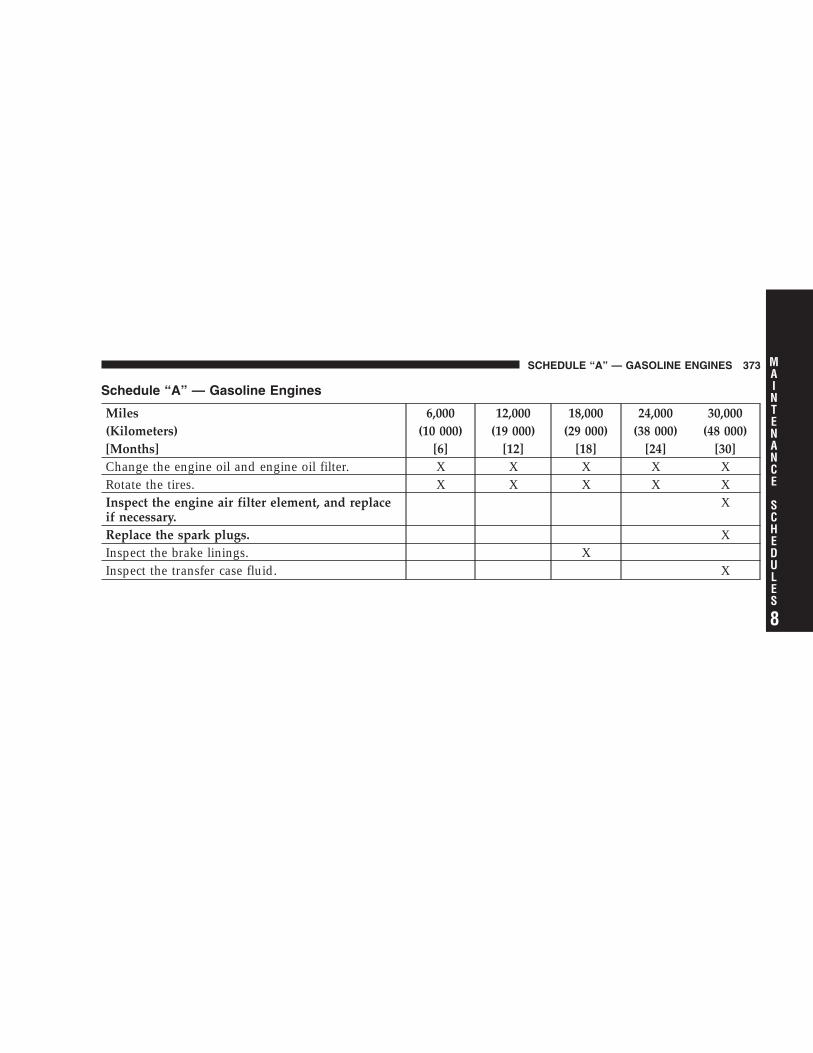
Schedule “A” — Gasoline Engines
Miles 6,000 12,000 18,000 24,000 30,000(Kilometers) (10 000) (19 000) (29 000) (38 000) (48 000)[Months] [6] [12] [18] [24] [30]Change the engine oil and engine oil filter. X X X X XRotate the tires. X X X X XInspect the engine air filter element, and replaceif necessary.
X
Replace the spark plugs. XInspect the brake linings. XInspect the transfer case fluid. X
SCHEDULE “A” — GASOLINE ENGINES 373
8
MAINTENANCE
SCHEDULES

Miles 36,000 42,000 48,000 54,000(Kilometers) (58 000) (67 000) (77 000) (86 000)[Months] [36] [42] [48] [54]Change the engine oil and engine oil filter. X X X XRotate the tires. X X X XInspect the brake linings. X X
374 SCHEDULE “A” — GASOLINE ENGINES
8
MAINTENANCE
SCHEDULES

Miles 60,000 66,000 72,000 78,000(Kilometers) (96 000) (106 000) (115 000) (125 000)[Months] [60] [66] [72] [78]Change the engine oil and engine oil filter. X X X XRotate the tires. X X X XInspect the engine air filter element, and replace if nec-essary.
X
Replace the spark plugs. XInspect the ignition cables, and replace if necessary(2.4L Only).
X
Inspect and replace the PCV valve, if necessary. XInspect the brake linings. XInspect the drive belt and replace, if needed. XInspect the drive belt and replace as needed. Not re-quired if previously replaced.
X
Flush and replace the engine coolant/anti-freeze at 60months, if not done at 102,000 miles (163 000 km).
X
Inspect the transfer case fluid. X
SCHEDULE “A” — GASOLINE ENGINES 375
8
MAINTENANCE
SCHEDULES

Miles 84,000 90,000 96,000 102,000(Kilometers) (134 000) (144 000) (154 000) (163 000)[Months] [84] [90] [96] [102]Change the engine oil and engine oil filter. X X X XRotate the tires. X X X XInspect the engine air filter element, and replace if nec-essary.
X
Replace the spark plugs. XInspect and replace the PCV valve, if necessary. XInspect the brake linings. XInspect the drive belt and replace as needed. Not requiredif previously replaced.
X X
Flush and replace the engine coolant/anti-freeze if notdone at 60 months.
X
Inspect the transfer case fluid. X
376 SCHEDULE “A” — GASOLINE ENGINES
8
MAINTENANCE
SCHEDULES

Miles 108,000 114,000 120,000(Kilometers) (173 000) (182 000) (192 000)[Months] [108] [114] [120]Change the engine oil and engine oil filter. X X XRotate the tires. X X XInspect the engine air filter element, and replace if necessary. XReplace the spark plugs. XInspect and replace the PCV valve, if necessary. XInspect the ignition cables, and replace if necessary (2.4L Only). XInspect the brake linings. XInspect the drive belt and replace as needed. Not required if pre-viously replaced.
X X
Flush and replace the engine coolant/anti-freeze if not done at102,000 miles (163 000 km).
X
Replace the timing belt (2.4L Only). XDrain and refill the transfer case fluid. X
Inspection and service should be performed anytime amalfunction is observed or suspected. Retain all receipts.
This maintenance is recommended by the manufac-turer to the owner, but it is not required to maintainemissions warranty.
SCHEDULE “A” — GASOLINE ENGINES 377
8
MAINTENANCE
SCHEDULES

MAINTENANCE SCHEDULES — DIESEL ENGINESThere are two maintenance schedules that show therequired service for your vehicle.
First is Schedule �B�. It is for vehicles that are operatedunder the conditions that are listed below and at thebeginning of the schedule.
• Day or night temperatures are below 32°F (0°C).
• Stop and go driving.
• Extensive engine idling.
• Driving in dusty conditions.
• Short trips of less than 10 miles (16.2 km).
• More than 50% of your driving is at sustained highspeeds during hot weather, above 90°F (32°C).
• Trailer towing.
• Taxi, police, or delivery service (commercial service).
• Off-road or desert driving.
NOTE: Most vehicles are operated under the conditionslisted for Schedule “B.”
Second is Schedule “A”. It is for vehicles that are notoperated under any of the conditions listed under Sched-ule “B.”
Use the schedule that best describes your driving condi-tions. Where time and mileage are listed, follow theinterval that occurs first.
CAUTION!
Failure to perform the required maintenance itemsmay result in damage to the vehicle.
378 SCHEDULE “A” — GASOLINE ENGINES
8
MAINTENANCE
SCHEDULES

At Each Stop for Fuel
• Check the engine oil level about 5 minutes after a fullywarmed engine is shut off. Checking the oil level whilethe vehicle is on level ground will improve the accu-racy of the oil level reading. Add oil only when thelevel is at or below the ADD or MIN mark.
• Check the windshield washer solvent, add as required.
Once a Month
• Check the tire pressure and look for unusual wear ordamage.
• Inspect the battery, clean and tighten the terminals asrequired.
• Check the fluid levels of engine coolant/anti-freezedeaeration bottle, brake master cylinder, and transmis-sion, and add as needed.
• Check all lights and all other electrical items for correctoperation.
At Each Oil Change
• Change the engine oil filter.
• Inspect the exhaust system.
• Inspect brake hoses.
• Check the engine coolant/anti-freeze level, hoses, andclamps.
• Inspect engine accessory drive belts. Replace as neces-sary.
• Inspect for the presence of water in the fuel filter/water separator unit.
Tire Rotation
• Rotate the tires every 6,000 miles (10 000 km).
SCHEDULE “A” — GASOLINE ENGINES 379
8
MAINTENANCE
SCHEDULES

Schedule “B” — Diesel EnginesFollow schedule “B” if you usually operate your vehicleunder one or more of the following conditions.
• Day or night temperatures are below 32°F (0°C).
• Stop and go driving.
• Extensive engine idling.
• Driving in dusty conditions.
• Short trips of less than 10 miles (16.2 km).
• More than 50% of your driving is at sustained highspeeds during hot weather, above 90°F (32°C).
• Trailer towing.
• Taxi, police, or delivery service (commercial service).
• Off-road or desert driving.
380 SCHEDULE “B” — DIESEL ENGINES
8
MAINTENANCE
SCHEDULES

Miles 6,250 12,500 18,750 25,000 31,250(Kilometers) (10 000) (20 000) (30 000) (40 000) (50 000)Change the engine oil and engine oil filter. X X X X XInspect the engine air filter element. Replace asnecessary.
X X X X X
Replace the engine air filter element. X XInspect the boost pressure solenoid filter. Replaceas necessary.
X X X X X
Replace the fuel filter/water separator unit. XInspect the brake linings. X XDrain and refill the front and rear axle fluid. X X
SCHEDULE “B” — DIESEL ENGINES 381
8
MAINTENANCE
SCHEDULES

Miles 37,500 43,750 50,000 56,250 62,500(Kilometers) (60 000) (70 000) (80 000) (90 000) (100 000)Change the engine oil and engine oil filter. X X X X XInspect the engine air filter element. Replace asnecessary.
X X X X X
Replace the engine air filter element. X X XInspect the boost pressure solenoid filter. Replaceas necessary.
X X X X X
Replace the boost pressure solenoid filter, if notpreviously replaced.
X
Replace the fuel filter/water separator unit. XReplace the engine accessory drive belt. XInspect the brake linings. X X XDrain and refill the front and rear axle fluid. X X XDrain and refill the transfer case fluid. XDrain and refill the automatic transmission fluid,and replace sump filter.
X
382 SCHEDULE “B” — DIESEL ENGINES
8
MAINTENANCE
SCHEDULES

Miles 68,750 75,000 81,250 87,500 93,750 100,000(Kilometers) (110 000) (120 000) (130 000) (140 000) (150 000) (160 000)Change the engine oil and engine oil filter. X X X X X XInspect the engine air filter element. Re-place as necessary.
X X X X X X
Replace the engine air filter element. X X XInspect the boost pressure solenoid filter. Re-place as necessary.
X X X X X X
Replace the boost pressure solenoid filter, ifnot previously replaced.
X
Replace the engine accessory drive belt. XReplace the engine timing belt and idler pul-leys.
X
Inspect the engine timing belt tensioner, re-place if necessary.†
X
Replace the fuel filter/water separator unit. X XFlush and replace the engine coolant/anti-freeze.
X
SCHEDULE “B” — DIESEL ENGINES 383
8
MAINTENANCE
SCHEDULES

Miles 68,750 75,000 81,250 87,500 93,750 100,000(Kilometers) (110 000) (120 000) (130 000) (140 000) (150 000) (160 000)Inspect the brake linings. X XDrain and refill the front and rear axle fluid. X X
Applies only if vehicle is used for frequent trailertowing, or fleet/commercial service.
† The replacement of such component is requested ifthere is superficial wear, bearing clearance, or evidentgrease leak.
Inspection and service should be performed anytime amalfunction is observed or suspected. Retain all receipts.
384 SCHEDULE “B” — DIESEL ENGINES
8
MAINTENANCE
SCHEDULES

Schedule “A” — Diesel Engines
Miles 12,500 25,000 37,500 50,000(Kilometers) (20 000) (40 000) (60 000) (80 000)Change the engine oil and engine oil filter. X X X XInspect the engine air filter element. Replace as neces-sary.
X X X X
Replace the engine air filter element. X XInspect the boost pressure solenoid filter. Replace as nec-essary.
X X X X
Replace the boost pressure solenoid filter, if not previ-ously replaced.
X
Replace the fuel filter/water separator unit. X XInspect the brake linings. X XInspect the transfer case fluid. X
SCHEDULE “A” — DIESEL ENGINES 385
8
MAINTENANCE
SCHEDULES

Miles 62,500 75,000 87,500 100,000(Kilometers) (100 000) (120 000) (140 000) (160 000)Change the engine oil and engine oil filter. X X X XInspect the engine air filter element. Replace as neces-sary.
X X X X
Replace the engine air filter element. X XInspect the boost pressure solenoid filter. Replace as nec-essary.
X X X X
Replace the boost pressure solenoid filter, if not previ-ously replaced.
X
Replace the fuel filter/water separator unit. X XReplace the engine timing belt, and idler pulleys. XInspect the engine timing belt tensioner, replace if neces-sary.†
X
Flush and replace the engine coolant. X
386 SCHEDULE “A” — DIESEL ENGINES
8
MAINTENANCE
SCHEDULES

Miles 62,500 75,000 87,500 100,000(Kilometers) (100 000) (120 000) (140 000) (160 000)Replace the engine accessory drive belt. XInspect the brake linings. X XInspect the transfer case fluid. X
† The replacement of such component is requested ifthere is superficial wear, bearing clearance, or evidentgrease leak.
Inspection and service should be performed anytime amalfunction is observed or suspected. Retain all receipts.
SCHEDULE “A” — DIESEL ENGINES 387
8
MAINTENANCE
SCHEDULES


IF YOU NEED CONSUMER ASSISTANCE
CONTENTS
� Suggestions For Obtaining Service For YourVehicle . . . . . . . . . . . . . . . . . . . . . . . . . . . . . . 390
▫ Prepare For The Appointment . . . . . . . . . . . . 390
▫ Prepare A List . . . . . . . . . . . . . . . . . . . . . . . . 390
▫ Be Reasonable With Requests . . . . . . . . . . . . . 390
� If You Need Assistance . . . . . . . . . . . . . . . . . . . 390
� Warranty Information . . . . . . . . . . . . . . . . . . . . 393
� Mopar� Parts . . . . . . . . . . . . . . . . . . . . . . . . . 395
� Reporting Safety Defects . . . . . . . . . . . . . . . . . . 395
▫ In Canada . . . . . . . . . . . . . . . . . . . . . . . . . . 395
� Publication Order Forms . . . . . . . . . . . . . . . . . . 396
9

SUGGESTIONS FOR OBTAINING SERVICE FORYOUR VEHICLE
Prepare For The AppointmentIf you’re having warranty work done, be sure to have theright papers with you. Take your warranty folder. Allwork to be performed may not be covered by thewarranty, discuss additional charges with the servicemanager. Keep a maintenance log of your vehicle’sservice history. This can often provide a clue to thecurrent problem.
Prepare A ListMake a written list of your vehicle’s problems or thespecific work you want done. If you’ve had an accident,or work done that is not on your maintenance log, let theservice advisor know.
Be Reasonable With RequestsIf you list a number of items, and you must have yourvehicle by the end of the day, discuss the situation withthe service advisor and list the items in order of priority.At many dealers you may obtain a rental vehicle at aminimal daily charge. If you need a rental, it is advisableto make these arrangements when you call for an ap-pointment.
IF YOU NEED ASSISTANCEThe manufacturer and its dealers are vitally interested inyour satisfaction. We want you to be happy with ourproducts and services.
Warranty service must be done by an authorizedChrysler, Dodge, or Jeep dealer. We strongly recommendthat you take your vehicle to you selling dealer. Theyknow you and your vehicle best, and are most concernedthat you get prompt and high quality service. Themanufacturer’s dealers have the facilities, factory-trained
390 IF YOU NEED CONSUMER ASSISTANCE

technicians, special tools, and the latest information toassure your vehicle is fixed correctly and in a timelymanner.
This is why you should always talk to your dealer’sservice manager first. Most matters can be resolved withthis process.
• If for some reason you are still not satisfied, talk to thegeneral manager or owner of the dealership. Theywant to know if you need assistance.
• If your dealership is unable to resolve the concern, youmay contact the Manufacturer’s Customer Center.
Any communication to the Manufacturer’s CustomerCenter should include the following information:
• Owner’s name and address
• Owner’s telephone number (home and office)
• Dealership name
• Vehicle identification number
• Vehicle delivery date and mileage
DaimlerChrysler Motors Corporation Customer CenterP.O. Box 21–8004Auburn Hills, MI 48321–8004Phone: (800) 992-1997
DaimlerChrysler Canada Inc. Customer CenterP.O. Box 1621Windsor, Ontario N9A 4H6Phone —(800) 465–2001
In Mexico contact:Av. Prolongacion Paseo de la Reforma, 1240Sante Fe C.P. 05109Mexico, D. F.In Mexico (915) 729–1248 or 729–1240Outside Mexico (525) 729–1248 or 729–1240
IF YOU NEED CONSUMER ASSISTANCE 391
9

Customer Assistance For The Hearing Or SpeechImpaired (TDD/TTY)To assist customers who have hearing difficulties, themanufacturer has installed special TDD (Telecommuni-cation Devices for the Deaf) equipment at its CustomerCenter. Any hearing or speech impaired customer whohas access to a TDD or a conventional teletypewriter(TTY) in the United States can communicate with themanufacturer by dialing 1–800–380–CHRY.
Service ContractYou may have purchased a service contract for yourvehicle to help protect you from the high cost of unex-pected repairs after your manufacturer’s new vehiclelimited warranty expires. The manufacturer stands be-hind only the manufacturer’s Service Contracts. If youpurchased a manufacturer’s Service Contract, you willreceive Plan Provisions and an Owner Identification Cardin the mail within three weeks of your vehicle deliverydate. If you have any questions about your service
contract, call the manufacturer’s Service Contract Na-tional Customer Hotline at 1-800-521-9922.
The manufacturer will not stand behind any servicecontract that is not the manufacturer’s Service Contract. Itis not responsible for any service contract other than themanufacturer’s Service Contract. If you purchased aservice contract that is not a manufacturer’s ServiceContract, and you require service after your manufactur-er’s new vehicle limited warranty expires, please refer toyour contract documents, and contact the person listed inthose documents.
We appreciate that you have made a major investmentwhen you purchased your new vehicle. Your dealer hasalso made a major investment in facilities, tools, andtraining to assure that you are absolutely delighted withyour ownership experience. You’ll be pleased with theirsincere efforts to resolve any warranty issues or relatedconcerns.
392 IF YOU NEED CONSUMER ASSISTANCE

WARRANTY INFORMATIONSee your manufacturer’s Warranty Information Bookletfor information on warranty coverage and transfer ofwarranty.
IF YOU NEED CONSUMER ASSISTANCE 393
9

U.S. ONLY
394 IF YOU NEED CONSUMER ASSISTANCE

MOPAR� PARTSMopar� fluids, lubricants, parts, and accessories areavailable from your dealer. They will help you keep yourvehicle operating at its best.
REPORTING SAFETY DEFECTSIn the 50 United States and Washington D.C.: If youbelieve that your vehicle has a defect which could causea crash or cause injury or death, you should immediatelyinform the National Highway Traffic Safety Administra-tion (NHTSA) in addition to notifying the manufacturer.
If NHTSA receives similar complaints, it may open aninvestigation, and if it finds that a safety defect exists ina group of vehicles, it may order a recall and remedycampaign. However, NHTSA cannot become involved inindividual problems between you, your dealer, and themanufacturer.
To contact NHTSA, you may either call the Auto SafetyHotline toll free at 1-800-424-9393 (or 366-0123 in Wash-ington DC area) or write to: NHTSA, U.S. Dept. ofTransportation, Washington DC 20590. You can alsoobtain other information about motor vehicle safety fromthe Hotline.
In Canada:If you believe that your vehicle has a safety defect, youshould contact the Customer Service Department imme-diately. Canadian customers who wish to report a safetydefect to the Canadian government should write toTransport Canada, Motor Vehicle Defect Investigationsand Recalls, 2780 Sheffield Road, Ottawa, Ontario K1B3V9.
IF YOU NEED CONSUMER ASSISTANCE 395
9
PUBLICATION ORDER FORMSTo order the following manuals, you may use either thewebsite or the phone numbers listed below. Visa, Mas-tercard, American Express, and Discover orders are ac-cepted. If you prefer mailing your payment, please callfor an order form.
NOTE: A street address is required when orderingmanuals. (No P.O. Boxes).
• Service Manuals.
These comprehensive service manuals provide theinformation that students and professional techniciansneed in diagnosing/troubleshooting, problem solving,maintaining, servicing and repairing DaimlerChryslerCorporation vehicles. A complete working knowledgeof the vehicle, system and/or components is written instraightforward language with illustrations, diagramsand charts.
• Diagnostic Procedure Manuals.
Filled with diagrams, charts and detailed illustrations,these practical manuals make it easy for students andtechnicians to find and fix problems on computer-controlled vehicle systems and features. They showexactly how to find and correct problems the first time,using step-by-step troubleshooting and driveabilityprocedures, proven diagnostic tests and a complete listof all tools and equipment.
• Owner’s Manuals.
These manuals have been prepared with the assistanceof service and engineering specialists to acquaint youwith specific Chrysler group vehicles. Included arestarting, operating, emergency and maintenance pro-cedures as well as specifications, capabilities andsafety tips.
396 IF YOU NEED CONSUMER ASSISTANCE
Call Toll Free at:
• 1–800–890–4038 (U.S.)
• 1–800–387–1143 (Canada)
Or
Visit us on the World Wide Web at:
• www.techauthority.daimlerchrysler.com
• www.daimlerchrysler.ca/manuals
IF YOU NEED CONSUMER ASSISTANCE 397
9


INDEX
10

ABS (Anti-Lock Brake) System . . . . . . . . . . . . 170,247Adding Washer Fluid . . . . . . . . . . . . . . . . . . . . . 157Air Cleaner, Engine (Engine Air Cleaner Filter) . . . 319Air Conditioner Maintenance . . . . . . . . . . . . . . . 321Air Conditioning, Operating Tips . . . . . . . . . . . . 214Air Conditioning Refrigerant . . . . . . . . . . . . . . . 322Air Filter . . . . . . . . . . . . . . . . . . . . . . . . . . . . . . 319Air Pressure, Tires . . . . . . . . . . . . . . . . . . . . . . . 263Airbag . . . . . . . . . . . . . . . . . . . . . . . . . . . . . . . . 48Airbag Deployment . . . . . . . . . . . . . . . . . . . . . . . 59Airbag Light . . . . . . . . . . . . . . . . . . . . . . . 53,62,174Airbag Maintenance . . . . . . . . . . . . . . . . . . . . . . . 62Airbag, Window . . . . . . . . . . . . . . . . . . . . . . . . . 49Alarm . . . . . . . . . . . . . . . . . . . . . . . . . . . . . . . . 30Alarm, Panic . . . . . . . . . . . . . . . . . . . . . . . . . . . . 27Alignment and Balance . . . . . . . . . . . . . . . . . . . 267Alterations/Modifications, Vehicle . . . . . . . . . . . . . 9Antenna, Satellite Radio . . . . . . . . . . . . . . . . . . . 207Antifreeze (Engine Coolant) . . . . . . . . . . . . . . . . 356
Anti-Lock Brake System (ABS) . . . . . . . . . . . . . . 247Anti-Lock Warning Light . . . . . . . . . . . . . . . . . . 170Appearance Care . . . . . . . . . . . . . . . . . . . . . . . . 337Arming Theft System . . . . . . . . . . . . . . . . . . . . . . 30Auto Down Power Windows . . . . . . . . . . . . . . . . 36Automatic Dimming Mirror . . . . . . . . . . . . . . . . . 82Automatic Door Locks . . . . . . . . . . . . . . . . . . . . . 23Automatic Transmission . . . . . . . . . . . . . . . . 230,333
Adding Fluid . . . . . . . . . . . . . . . . . . . . . . . . . 335Fluid and Filter Changes . . . . . . . . . . . . . . . . . 333Fluid Level Check . . . . . . . . . . . . . . . . . . . . . . 334Fluid Type . . . . . . . . . . . . . . . . . . . . . . . . . . . 333Gear Ranges . . . . . . . . . . . . . . . . . . . . . . . . . . 231Shifting . . . . . . . . . . . . . . . . . . . . . . . . . . . . . 230Special Additives . . . . . . . . . . . . . . . . . . . . . . 335Torque Converter . . . . . . . . . . . . . . . . . . . . . . 235
Auxiliary Electrical Outlet . . . . . . . . . . . . . . . . . . 148Auxiliary Power Outlet . . . . . . . . . . . . . . . . . . . 148
400 INDEX

Bar, Light . . . . . . . . . . . . . . . . . . . . . . . . . . 121,354Battery . . . . . . . . . . . . . . . . . . . . . . . . . . . . . . . 320
Emergency Starting . . . . . . . . . . . . . . . . . . . . . 299Keyless Transmitter Replacement . . . . . . . . . . . . 29Saving Feature (Protection) . . . . . . . . . . . . . . . 120
Belts, Drive . . . . . . . . . . . . . . . . . . . . . . . . . . . . 316Body Mechanism Lubrication . . . . . . . . . . . . . . . 323B-Pillar Location . . . . . . . . . . . . . . . . . . . . . . . . 258Brake System . . . . . . . . . . . . . . . . . . . . . . . . . . . 330
Anti-Lock . . . . . . . . . . . . . . . . . . . . . . . . . 170,247Hoses . . . . . . . . . . . . . . . . . . . . . . . . . . . . . . 331Master Cylinder . . . . . . . . . . . . . . . . . . . . . . . 332Parking . . . . . . . . . . . . . . . . . . . . . . . . . . . . . 245Warning Light . . . . . . . . . . . . . . . . . . . . . . . . 173
Brake/Transmission Interlock . . . . . . . . . . . . . . . 230Break-In Recommendations, New Vehicle . . . . . . . . 73Bulb Replacement . . . . . . . . . . . . . . . . . . . . . 350,351Bulbs, Light . . . . . . . . . . . . . . . . . . . . . . . . . . . . 350
Calibration, Compass . . . . . . . . . . . . . . . . . . . . . 137Capacities, Fluid . . . . . . . . . . . . . . . . . . . . . . . . 356Caps, Filler
Fuel . . . . . . . . . . . . . . . . . . . . . . . . . . . . . . . . 281Radiator (Coolant Pressure) . . . . . . . . . . . . . . . 327
Car Washes . . . . . . . . . . . . . . . . . . . . . . . . . . . . 338Carbon Monoxide Warning . . . . . . . . . . . . . . 141,280Cargo Area Cover . . . . . . . . . . . . . . . . . . . . . . . 151Cargo Area Features . . . . . . . . . . . . . . . . . . . . . . 151Cargo Compartment
Light . . . . . . . . . . . . . . . . . . . . . . . . . . . . 117,151Luggage Carrier . . . . . . . . . . . . . . . . . . . . . . . 159
Cargo Light . . . . . . . . . . . . . . . . . . . . . . . . . 117,151Cargo Organizer . . . . . . . . . . . . . . . . . . . . . . . . 154Cargo Tie-Downs . . . . . . . . . . . . . . . . . . . . . . . . 152Carpeting . . . . . . . . . . . . . . . . . . . . . . . . . . . . . 341Cassette Tape and Player Maintenance . . . . . . . . . 210Cassette Tape Player . . . . . . . . . . . . . . . . . . . . . 178Catalytic Converter . . . . . . . . . . . . . . . . . . . . . . 317
INDEX 401
10

Caution, Exhaust Gas . . . . . . . . . . . . . . . . . . . 73,141CD Changer . . . . . . . . . . . . . . . . . . . . . . . . 187,193CD Player . . . . . . . . . . . . . . . . . . 184,189,191,195,198CD Player Maintenance . . . . . . . . . . . . . . . . . . . 211Cellular Phone . . . . . . . . . . . . . . . . . . . . . . . . 85,211Center High Mounted Stop Light . . . . . . . . . . . . 355Chains, Tire . . . . . . . . . . . . . . . . . . . . . . . . . . . . 274Changing A Flat Tire . . . . . . . . . . . . . . . . . . . . . 294Charging System Light . . . . . . . . . . . . . . . . . . . . 170Chart, Tire Sizing . . . . . . . . . . . . . . . . . . . . . . . . 255Check Engine Light (Malfunction Indicator Light) . 310Child Restraint . . . . . . . . . . . . . . . . . . . . . . 63,68,70Child Restraint Tether Anchors . . . . . . . . . . . . . 67,68Child Safety Locks . . . . . . . . . . . . . . . . . . . . . . . . 24Climate Control . . . . . . . . . . . . . . . . . . . . . . . . . 212Clock . . . . . . . . . . . . . . . . . . . . . . . . . . . . . . . . 176Clutch Interlocking Ignition System . . . . . . . . 220,229Command-Trac Operation . . . . . . . . . . . . . . . . . . 236Compact Disc Maintenance . . . . . . . . . . . . . . . . . 211
Compact Disc Player . . . . . . . . . . . . . . . . . . 178,184Compass . . . . . . . . . . . . . . . . . . . . . . . . . . . . . . 137Compass Calibration . . . . . . . . . . . . . . . . . . . . . 137Compass Variance . . . . . . . . . . . . . . . . . . . . . . . 138Computer, Trip/Travel . . . . . . . . . . . . . . . . . . . . 135Console, Overhead . . . . . . . . . . . . . . . . . . . . . . . 129Contract, Service . . . . . . . . . . . . . . . . . . . . . . . . 392Converter, Catalytic . . . . . . . . . . . . . . . . . . . . . . 317Cool Down, Turbo . . . . . . . . . . . . . . . . . . . . . . . 224Cooling System . . . . . . . . . . . . . . . . . . . . . . . . . 325
Adding Coolant (Antifreeze) . . . . . . . . . . . . . . 327Coolant Capacity . . . . . . . . . . . . . . . . . . . . . . 356Coolant Level . . . . . . . . . . . . . . . . . . . . . . . . . 328Disposal of Used Coolant . . . . . . . . . . . . . . . . 328Drain, Flush, and Refill . . . . . . . . . . . . . . . . . . 326Inspection . . . . . . . . . . . . . . . . . . . . . . . . . . . 325Points to Remember . . . . . . . . . . . . . . . . . . . . 329Pressure Cap . . . . . . . . . . . . . . . . . . . . . . . . . 327Radiator Cap . . . . . . . . . . . . . . . . . . . . . . . . . 327
402 INDEX

Selection of Coolant . . . . . . . . . . . . . . . . . . 326,356Temperature Gauge . . . . . . . . . . . . . . . . . . . . . 171
Crankcase Emission Control System . . . . . . . . . . 319Cruise Control (Speed Control) . . . . . . . . . . . . . . 127Cruise Light . . . . . . . . . . . . . . . . . . . . . . . . . . . 172Cup Holder . . . . . . . . . . . . . . . . . . . . . . . . . . . . 150Customer Assistance . . . . . . . . . . . . . . . . . . . . . 390Cylinder, Retest Requirements . . . . . . . . . . . . . . . 120
Daytime Running Lights . . . . . . . . . . . . . . . . . . . 120Dealer Service . . . . . . . . . . . . . . . . . . . . . . . . . . 312Defroster, Rear Window . . . . . . . . . . . . . . . . . . . 158Diagnostic System, Onboard . . . . . . . . . . . . . . . . 309Diesel Engine Maintenance . . . . . . . . . . . . . . . . . 378Diesel Fuel System, Re-Priming . . . . . . . . . . . . . . 225Diesel Fuel Water Separator . . . . . . . . . . . . . . . . 225Dimmer Switch, Headlight . . . . . . . . . . . . . . . . . 119Dipsticks
Oil (Engine) . . . . . . . . . . . . . . . . . . . . . . . . . . 312
Power Steering . . . . . . . . . . . . . . . . . . . . . . . . 322Disabled Vehicle Towing . . . . . . . . . . . . . . . . . . . 302Disarming, Theft System . . . . . . . . . . . . . . . . . . . 31Disposal
Engine Oil . . . . . . . . . . . . . . . . . . . . . . . . . . . 316Used Engine Fluids . . . . . . . . . . . . . . . . . . . . . 316
Door Locks . . . . . . . . . . . . . . . . . . . . . . . . . . . . . 20Door Locks, Automatic . . . . . . . . . . . . . . . . . . . . 23Door Opener, Garage . . . . . . . . . . . . . . . . . . . . . 139Doors . . . . . . . . . . . . . . . . . . . . . . . . . . . . . . . . . 20Drive Belts . . . . . . . . . . . . . . . . . . . . . . . . . . . . 316Driving . . . . . . . . . . . . . . . . . . . . . . . . . . . . . . . 249
Off-Pavement . . . . . . . . . . . . . . . . . . . . . . . . . 249Off-Road . . . . . . . . . . . . . . . . . . . . . . . . . . . . 249
Electric Remote Mirrors . . . . . . . . . . . . . . . . . . . . 83Electrical Outlet, Auxiliary . . . . . . . . . . . . . . . . . 148Electrical Power Outlets . . . . . . . . . . . . . . . . . . . 148Electronic Speed Control . . . . . . . . . . . . . . . . . . . 127
INDEX 403
10

Electronic Throttle Control Warning Light . . . . . . 175Electronic Vehicle Information Center . . . . . . . . . 131Emergency, In Case of
Freeing Vehicle When Stuck . . . . . . . . . . . . . . . 236Hazard Warning Flasher . . . . . . . . . . . . . . . . . 292Jacking . . . . . . . . . . . . . . . . . . . . . . . . . . . . . 294Jump Starting . . . . . . . . . . . . . . . . . . . . . . . . . 299Tow Hooks . . . . . . . . . . . . . . . . . . . . . . . . . . 301
Emission Control System Maintenance . . . . . . 310,360Engine
Air Cleaner . . . . . . . . . . . . . . . . . . . . . . . . . . 319Block Heater . . . . . . . . . . . . . . . . . . . . . . . . . 226Break-In Recommendations . . . . . . . . . . . . . . . . 73Checking Oil Level . . . . . . . . . . . . . . . . . . . . . 312Compartment . . . . . . . . . . . . . . . . . . . . . . 306,307Compartment Identification . . . . . . . . . . . . 306,307Cooling . . . . . . . . . . . . . . . . . . . . . . . . . . . . . 325Exhaust Gas Caution . . . . . . . . . . . . . . . . . . . . 280Fails to Start . . . . . . . . . . . . . . . . . . . . . . . . . . 222
Flooded, Starting . . . . . . . . . . . . . . . . . . . . . . 222Fuel Requirements . . . . . . . . . . . . . . . . . . 276,356Jump Starting . . . . . . . . . . . . . . . . . . . . . . . . . 299Malfunction Indicator . . . . . . . . . . . . . . . . . . . 169Oil . . . . . . . . . . . . . . . . . . . . . . . . . . . . . . 312,356Oil Change Interval . . . . . . . . . . . . . . . . . . . . 313Oil Disposal . . . . . . . . . . . . . . . . . . . . . . . . . . 316Oil Filter . . . . . . . . . . . . . . . . . . . . . . . . . . . . 316Oil Filter Disposal . . . . . . . . . . . . . . . . . . . . . . 316Oil Selection . . . . . . . . . . . . . . . . . . . . 314,315,356Oil Synthetic . . . . . . . . . . . . . . . . . . . . . . . . . 315Overheating . . . . . . . . . . . . . . . . . . . . . . . . . . 293Starting . . . . . . . . . . . . . . . . . . . . . . . . . . . . . 220Temperature Gauge . . . . . . . . . . . . . . . . . . . . . 171Timing Belt . . . . . . . . . . . . . . . . . . . . . . . . . . 319
Engine Oil Viscosity . . . . . . . . . . . . . . . . . . . 314,315Engine Oil Viscosity Chart . . . . . . . . . . . . . . 314,315Enhanced Accident Response Feature . . . . . . . . . . 61Entry System, Illuminated . . . . . . . . . . . . . . . . . . 19
404 INDEX

Exhaust Gas Caution . . . . . . . . . . . . . . . . . . . 73,280Exhaust System . . . . . . . . . . . . . . . . . . . . . . . . . 324Exterior Finish Care . . . . . . . . . . . . . . . . . . . . . . 338
FiltersAir Cleaner . . . . . . . . . . . . . . . . . . . . . . . . . . 319Engine Oil . . . . . . . . . . . . . . . . . . . . . . . . . . . 316
Finish Care . . . . . . . . . . . . . . . . . . . . . . . . . . . . 338Flashers
Hazard Warning . . . . . . . . . . . . . . . . . . . . . . . 292Turn Signal . . . . . . . . . . . . . . . . . . . . . 168,352,355
Flooded Engine Starting . . . . . . . . . . . . . . . . . . . 222Fluid Capacities . . . . . . . . . . . . . . . . . . . . . . . . . 356Fluid Leaks . . . . . . . . . . . . . . . . . . . . . . . . . . . . . 75Fluid Level Checks . . . . . . . . . . . . . . . . . . . . . . . 75
Automatic Transmission . . . . . . . . . . . . . . . . . 333Clutch Fluid . . . . . . . . . . . . . . . . . . . . . . . . . . 335Engine Oil . . . . . . . . . . . . . . . . . . . . . . . . . . . 312Manual Transmission . . . . . . . . . . . . . . . . . . . 335
Power Steering . . . . . . . . . . . . . . . . . . . . . . . . 322Fog Light Service . . . . . . . . . . . . . . . . . . . . . . . . 353Fog Lights . . . . . . . . . . . . . . . . . . . . . . . . . . 120,353Folding Rear Seat . . . . . . . . . . . . . . . . . . . . . . . . 113Four Wheel Drive . . . . . . . . . . . . . . . . . . . . . . . 236
Operation . . . . . . . . . . . . . . . . . . . . . . . . . . . 236Shifting . . . . . . . . . . . . . . . . . . . . . . . . . . 239,243Systems . . . . . . . . . . . . . . . . . . . . . . . . . . 236,240
Four-Way Hazard Flasher . . . . . . . . . . . . . . . . . . 292Freeing A Stuck Vehicle . . . . . . . . . . . . . . . . . . . 236Front Axle . . . . . . . . . . . . . . . . . . . . . . . . . . . . . 337Fuel . . . . . . . . . . . . . . . . . . . . . . . . . . . . . . 276,280
Diesel . . . . . . . . . . . . . . . . . . . . . . . . . . . . . . 280Filler Cap . . . . . . . . . . . . . . . . . . . . . . . . . . . . 281Filler Door . . . . . . . . . . . . . . . . . . . . . . . . . . . 281Gasoline . . . . . . . . . . . . . . . . . . . . . . . . . . . . 276Gauge . . . . . . . . . . . . . . . . . . . . . . . . . . . . . . 174Materials Added . . . . . . . . . . . . . . . . . . . . . . . 279Octane Rating . . . . . . . . . . . . . . . . . . . . . . . . 276
INDEX 405
10

Requirements . . . . . . . . . . . . . . . . . . . 276,280,356Tank Capacity . . . . . . . . . . . . . . . . . . . . . . . . 356
Fuel System Caution . . . . . . . . . . . . . . . . . . . 279,283Fuses . . . . . . . . . . . . . . . . . . . . . . . . . . . . . . . . 342
Garage Door Opener . . . . . . . . . . . . . . . . . . . . . 139Gas Cap . . . . . . . . . . . . . . . . . . . . . . . . . . . 281,309Gasoline . . . . . . . . . . . . . . . . . . . . . . . . . . . . . . 276Gasoline, Reformulated . . . . . . . . . . . . . . . . . . . 277Gasoline/Oxygenate Blends . . . . . . . . . . . . . . . . 278Gauges
Coolant Temperature . . . . . . . . . . . . . . . . . . . . 171Fuel . . . . . . . . . . . . . . . . . . . . . . . . . . . . . . . . 174Odometer . . . . . . . . . . . . . . . . . . . . . . . . . . . 171Speedometer . . . . . . . . . . . . . . . . . . . . . . . . . 168Tachometer . . . . . . . . . . . . . . . . . . . . . . . . . . 168
Gear Ranges . . . . . . . . . . . . . . . . . . . . . . . . 229,231General Information . . . . . . . . . . . . . . . . . . . . . . 273Glass Cleaning . . . . . . . . . . . . . . . . . . . . . . . . . . 340
Hands-Free Phone . . . . . . . . . . . . . . . . . . . . . . . . 85Hazard Warning Flasher . . . . . . . . . . . . . . . . . . . 292Head Restraints . . . . . . . . . . . . . . . . . . . . . . . . . 110Head Rests . . . . . . . . . . . . . . . . . . . . . . . . . . . . 110Headlights . . . . . . . . . . . . . . . . . . . . . . . . . . . . 119
Bulb Replacement . . . . . . . . . . . . . . . . . . . . . . 351High Beam . . . . . . . . . . . . . . . . . . . . . . . . . . . 168Lights On Reminder . . . . . . . . . . . . . . . . . . . . 120Passing . . . . . . . . . . . . . . . . . . . . . . . . . . . . . 119Replacing . . . . . . . . . . . . . . . . . . . . . . . . . . . . 351Switch . . . . . . . . . . . . . . . . . . . . . . . . . . . . . . 119
Heated Mirrors . . . . . . . . . . . . . . . . . . . . . . . . . . 84Heated Seats . . . . . . . . . . . . . . . . . . . . . . . . . . . 112Heater, Engine Block . . . . . . . . . . . . . . . . . . . . . 226Holder, Cup . . . . . . . . . . . . . . . . . . . . . . . . . . . 150Homelink Transmitter . . . . . . . . . . . . . . . . . . . . 139Hood Release . . . . . . . . . . . . . . . . . . . . . . . . . . 116Hoses . . . . . . . . . . . . . . . . . . . . . . . . . . . . . . . . 330Hydraulic Clutch Fluid . . . . . . . . . . . . . . . . . . . . 335
406 INDEX

Identifying Your Engine . . . . . . . . . . . . . . . . 306,307Ignition
Key . . . . . . . . . . . . . . . . . . . . . . . . . . . . . . . . . 14Wiring System . . . . . . . . . . . . . . . . . . . . . . . . 319
Illuminated Entry . . . . . . . . . . . . . . . . . . . . . . . . 19Inflation Pressure Tires . . . . . . . . . . . . . . . . . . . . 263Information Center, Vehicle . . . . . . . . . . . . . . . . . 131Inside Rearview Mirror . . . . . . . . . . . . . . . . . . . . 81Instrument Cluster . . . . . . . . . . . . . . . . . . . . . . . 166Instrument Panel and Controls . . . . . . . . . . . . . . 165Interior Appearance Care . . . . . . . . . . . . . . . . . . 340Interior Fuses . . . . . . . . . . . . . . . . . . . . . . . . . . 342Interior Lighting . . . . . . . . . . . . . . . . . . . . . . . . 117Interior Lights . . . . . . . . . . . . . . . . . . . . . . . . . . 117Intermittent Wipers . . . . . . . . . . . . . . . . . . . . . . 125Introduction . . . . . . . . . . . . . . . . . . . . . . . . . . . . . 4
Jack Location . . . . . . . . . . . . . . . . . . . . . . . . . . . 295Jack Operation . . . . . . . . . . . . . . . . . . . . . . . 294,296
Jacking Instructions . . . . . . . . . . . . . . . . . . . . . . 296Jump Starting . . . . . . . . . . . . . . . . . . . . . . . . . . 299
Key, Programming . . . . . . . . . . . . . . . . . . . . . . . . 18Key Release Button . . . . . . . . . . . . . . . . . . . . . . . 15Key, Replacement . . . . . . . . . . . . . . . . . . . . . . . . 17Key, Sentry . . . . . . . . . . . . . . . . . . . . . . . . . . . . . 16Key-In Reminder . . . . . . . . . . . . . . . . . . . . . . . . . 16Keyless Entry System . . . . . . . . . . . . . . . . . . . . . . 25Keys . . . . . . . . . . . . . . . . . . . . . . . . . . . . . . . . . 14
Lane Change and Turn Signals . . . . . . . . . . . . . . 168Lap/Shoulder Belts . . . . . . . . . . . . . . . . . . . . . . . 38LATCH(Lower Anchors and Tether for CHildren) . . . . . 67,68Lead Free Gasoline . . . . . . . . . . . . . . . . . . . . . . 276Light Bar . . . . . . . . . . . . . . . . . . . . . . . . . . . 121,354Lights . . . . . . . . . . . . . . . . . . . . . . . . . . . . . 117,350
Airbag . . . . . . . . . . . . . . . . . . . . . . . . . . . . 62,174
INDEX 407
10
Anti-Lock . . . . . . . . . . . . . . . . . . . . . . . . . . . 170Back-Up . . . . . . . . . . . . . . . . . . . . . . . . . . . . . 355Battery Saver . . . . . . . . . . . . . . . . . . . . . . . . . 120Brake Warning . . . . . . . . . . . . . . . . . . . . . . . . 173Bulb Replacement . . . . . . . . . . . . . . . . . . . . . . 351Cargo . . . . . . . . . . . . . . . . . . . . . . . . . . . . 117,151Center Mounted Stop . . . . . . . . . . . . . . . . . . . 355Cruise . . . . . . . . . . . . . . . . . . . . . . . . . . . . . . 172Daytime Running . . . . . . . . . . . . . . . . . . . . . . 120Dimmer Switch, Headlight . . . . . . . . . . . . . 117,119Dome . . . . . . . . . . . . . . . . . . . . . . . . . . . . . . 130Electronic Throttle Control Warning . . . . . . . . . 175Fog . . . . . . . . . . . . . . . . . . . . . . . . . . . . . 120,353Four-Wheel Drive Indicator . . . . . . . . . . . . . . . 169Fuses . . . . . . . . . . . . . . . . . . . . . . . . . . . . . . . 342Hazard Warning Flasher . . . . . . . . . . . . . . . . . 292Headlight Switch . . . . . . . . . . . . . . . . . . . . . . 119Headlights . . . . . . . . . . . . . . . . . . . . . . . . 119,351Headlights On Reminder . . . . . . . . . . . . . . . . . 120
Headlights On With Wipers . . . . . . . . . . . . . . . 119High Beam Indicator . . . . . . . . . . . . . . . . . . . . 168Instrument Cluster . . . . . . . . . . . . . . . . . . . . . 119Intensity Control . . . . . . . . . . . . . . . . . . . . . . . 117Interior . . . . . . . . . . . . . . . . . . . . . . . . . . . . . 117Lights On Reminder . . . . . . . . . . . . . . . . . . . . 120Low Fuel . . . . . . . . . . . . . . . . . . . . . . . . . . . . 174Malfunction Indicator . . . . . . . . . . . . . . . . . . . 169Map Reading . . . . . . . . . . . . . . . . . . . . . . . . . 118Oil Pressure . . . . . . . . . . . . . . . . . . . . . . . . . . 172Park . . . . . . . . . . . . . . . . . . . . . . . . . . . . . . . 119Passing . . . . . . . . . . . . . . . . . . . . . . . . . . . . . 119Reading . . . . . . . . . . . . . . . . . . . . . . . . . . . . . 130Rear Servicing . . . . . . . . . . . . . . . . . . . . . . . . 355Rear Tail . . . . . . . . . . . . . . . . . . . . . . . . . . . . 355Seat Belt Reminder . . . . . . . . . . . . . . . . . . . . . 175Service . . . . . . . . . . . . . . . . . . . . . . . . . . . . . . 351Side Marker . . . . . . . . . . . . . . . . . . . . . . . . . . 355Transfer Case . . . . . . . . . . . . . . . . . . . . . . 173,174
408 INDEX

Transmission Warning . . . . . . . . . . . . . . . . . . . 172Turn Signal . . . . . . . . . . . . . . . . . . 119,168,352,355Warning (Instrument Cluster Description) . . . . . 168
Loading VehicleTires . . . . . . . . . . . . . . . . . . . . . . . . . . . . . . . 258
LocksAutomatic Door . . . . . . . . . . . . . . . . . . . . . . . . 23Child Protection . . . . . . . . . . . . . . . . . . . . . . . . 24Door . . . . . . . . . . . . . . . . . . . . . . . . . . . . . . . . 20Power Door . . . . . . . . . . . . . . . . . . . . . . . . . . . 23Steering Wheel . . . . . . . . . . . . . . . . . . . . . . . . . 19
Lower Anchors and Tether for CHildren(LATCH) . . . . . . . . . . . . . . . . . . . . . . . . . . . . 67,68Lubrication, Body . . . . . . . . . . . . . . . . . . . . . . . 323Luggage Carrier . . . . . . . . . . . . . . . . . . . . . . . . . 159Luggage Rack . . . . . . . . . . . . . . . . . . . . . . . . . . 159
Maintenance Free Battery . . . . . . . . . . . . . . . . . . 320Maintenance Procedures . . . . . . . . . . . . . . . . . . . 312
Maintenance Schedule . . . . . . . . . . . . . . . . . 360,378Diesel . . . . . . . . . . . . . . . . . . . . . . . . . . . . . . 378Light Duty Schedule �A� . . . . . . . . . . . . . . 373,385Light Duty Schedule �B� . . . . . . . . . . . . . . . 363,380Schedule �A� . . . . . . . . . . . . . . . . . . . . . . . 373,385Schedule �B� . . . . . . . . . . . . . . . . . . . . . . . 363,380
Maintenance, Sunroof . . . . . . . . . . . . . . . . . . . . . 147Malfunction Indicator Light . . . . . . . . . . . . . . 169,310Manual, Service . . . . . . . . . . . . . . . . . . . . . . . . . 396Manual Transmission . . . . . . . . . . . . . . . . . . 227,335
Fluid Level Check . . . . . . . . . . . . . . . . . . . . . . 335Lubricant Selection . . . . . . . . . . . . . . . . . . . . . 335Shift Speeds . . . . . . . . . . . . . . . . . . . . . . . . . . 229
Map/Reading Lights . . . . . . . . . . . . . . . . . . . . . 130Master Cylinder . . . . . . . . . . . . . . . . . . . . . . . . . 332Mini-Trip Computer . . . . . . . . . . . . . . . . . . . . . . 135Mirrors . . . . . . . . . . . . . . . . . . . . . . . . . . . . . . . . 81
Automatic Dimming . . . . . . . . . . . . . . . . . . . . . 82Electric Remote . . . . . . . . . . . . . . . . . . . . . . . . 83
INDEX 409
10
Heated . . . . . . . . . . . . . . . . . . . . . . . . . . . . . . 84Outside . . . . . . . . . . . . . . . . . . . . . . . . . . . . . . 82Rearview . . . . . . . . . . . . . . . . . . . . . . . . . . . . . 81Vanity . . . . . . . . . . . . . . . . . . . . . . . . . . . . . . . 84
Modifications/Alterations, Vehicle . . . . . . . . . . . . . 9Monitor, Tire Pressure System . . . . . . . . . . . . . . . 268Mopar Parts . . . . . . . . . . . . . . . . . . . . . . . . . 311,395Multi-Function Control Lever . . . . . . . . . . . . . . . 118
Navigation System . . . . . . . . . . . . . . . . . . . . . . . 203New Vehicle Break-In Period . . . . . . . . . . . . . . . . 73
Occupant Classification System . . . . . . . . . . . . . . . 55Occupant Restraints . . . . . . . . . . . . . . . . . . . . . . . 37Octane Rating, Gasoline . . . . . . . . . . . . . . . . . . . 276Odometer . . . . . . . . . . . . . . . . . . . . . . . . . . . . . 171
Trip . . . . . . . . . . . . . . . . . . . . . . . . . . . . . . . . 171Off-Pavement Driving . . . . . . . . . . . . . . . . . . 249,341Off-Road Driving . . . . . . . . . . . . . . . . . . . . . 249,341
Oil, Engine . . . . . . . . . . . . . . . . . . . . . . . . . . . . 312Capacity . . . . . . . . . . . . . . . . . . . . . . . . . . . . 356Change Interval . . . . . . . . . . . . . . . . . . . . . . . 313Checking . . . . . . . . . . . . . . . . . . . . . . . . . . . . 312Dipstick . . . . . . . . . . . . . . . . . . . . . . . . . . . . . 312Identification Logo . . . . . . . . . . . . . . . . . . . . . 314Materials Added to . . . . . . . . . . . . . . . . . . . . . 315Pressure Warning Light . . . . . . . . . . . . . . . . . . 172Recommendation . . . . . . . . . . . . . . . . . 314,315,356Synthetic . . . . . . . . . . . . . . . . . . . . . . . . . . . . 315Viscosity . . . . . . . . . . . . . . . . . . . . . . . 314,315,356
Oil Filter, Selection . . . . . . . . . . . . . . . . . . . . . . . 316Oil Pressure Light . . . . . . . . . . . . . . . . . . . . . . . 172Onboard Diagnostic System . . . . . . . . . . . . . . 309,310Opener, Garage Door . . . . . . . . . . . . . . . . . . . . . 139Organizer, Cargo . . . . . . . . . . . . . . . . . . . . . . . . 154Outside Rearview Mirrors . . . . . . . . . . . . . . . . . . 82Overhead Console . . . . . . . . . . . . . . . . . . . . . . . 129Overheating, Engine . . . . . . . . . . . . . . . . . . . . . . 293
410 INDEX

Owner’s Manual . . . . . . . . . . . . . . . . . . . . . . . . 396
Paint Care . . . . . . . . . . . . . . . . . . . . . . . . . . . . . 337Paint Damage . . . . . . . . . . . . . . . . . . . . . . . . . . 337Panic Alarm . . . . . . . . . . . . . . . . . . . . . . . . . . . . 27Parking Brake . . . . . . . . . . . . . . . . . . . . . . . . . . 245Passing Light . . . . . . . . . . . . . . . . . . . . . . . . . . . 119PCV Valve . . . . . . . . . . . . . . . . . . . . . . . . . . . . 319Pets . . . . . . . . . . . . . . . . . . . . . . . . . . . . . . . . . . 72Phone, Cellular . . . . . . . . . . . . . . . . . . . . . . . . . . 85Phone, Hands-Free . . . . . . . . . . . . . . . . . . . . . . . 85Placard, Tire and Loading Information . . . . . . . . . 259Polishing and Waxing . . . . . . . . . . . . . . . . . . . . . 338Power
Distribution Center . . . . . . . . . . . . . . . . . . . . . 345Door Locks . . . . . . . . . . . . . . . . . . . . . . . . . . . 23Mirrors . . . . . . . . . . . . . . . . . . . . . . . . . . . . . . 83Outlet . . . . . . . . . . . . . . . . . . . . . . . . . . . . . . 148Seats . . . . . . . . . . . . . . . . . . . . . . . . . . . . . . . 111
Steering . . . . . . . . . . . . . . . . . . . . . . . . . . . . . 322Sunroof . . . . . . . . . . . . . . . . . . . . . . . . . . . . . 145Windows . . . . . . . . . . . . . . . . . . . . . . . . . . . . . 35
Pregnant Women and Seat Belts . . . . . . . . . . . . . . 47Preparation for Jacking . . . . . . . . . . . . . . . . . . . . 296Pretensioners
Seat Belts . . . . . . . . . . . . . . . . . . . . . . . . . . . . . 46Programmable Electronic Features . . . . . . . . . . . . 132Programming Transmitters . . . . . . . . . . . . . . . . . . 28
Radial Ply Tires . . . . . . . . . . . . . . . . . . . . . . . . . 265Radio Broadcast Signals . . . . . . . . . . . . . . . . . . . 177Radio Operation . . . . . . . . . . . . . . . . . . . . . . 189,211Radio, Satellite . . . . . . . . . . . . . . . . . . . . . . . . . . 203Radio (Sound Systems) . . . . . . . . . . . . . . 178,189,195Rear Axle . . . . . . . . . . . . . . . . . . . . . . . . . . 245,337Rear Swing Gate . . . . . . . . . . . . . . . . . . . . . . . . . 31Rear Window Defroster . . . . . . . . . . . . . . . . . . . 158Rear Window Features . . . . . . . . . . . . . . . . . . . . 156
INDEX 411
10

Rear Wiper/Washer . . . . . . . . . . . . . . . . . . . . . . 156Rearview Mirrors . . . . . . . . . . . . . . . . . . . . . . . . 81Reclining Front Seats . . . . . . . . . . . . . . . . . . . . . 109Recommended Fluids, Lubricants and Genuine
Parts . . . . . . . . . . . . . . . . . . . . . . . . . . . . . . . 357Recreational Towing . . . . . . . . . . . . . . . . . . . . . . 287
Shifting into Transfer Case Neutral (N) . . . . . . . 287Shifting out of Transfer Case Neutral (N) . . . . . 288
Reformulated Gasoline . . . . . . . . . . . . . . . . . . . . 277Refrigerant . . . . . . . . . . . . . . . . . . . . . . . . . . . . 322Reminder, Lights On . . . . . . . . . . . . . . . . . . . . . 120Reminder, Seat Belt . . . . . . . . . . . . . . . . . . . . . . . 46Remote Keyless Entry . . . . . . . . . . . . . . . . . . . . . 25Remote Sound System Controls . . . . . . . . . . . . . . 208Replacement Keys . . . . . . . . . . . . . . . . . . . . . . . . 17Replacement Parts . . . . . . . . . . . . . . . . . . . . . . . 311Replacement Tires . . . . . . . . . . . . . . . . . . . . . . . 266Reporting Safety Defects . . . . . . . . . . . . . . . . . . . 395Re-Priming Diesel Fuel System . . . . . . . . . . . . . . 225
Restraint, Head . . . . . . . . . . . . . . . . . . . . . . . . . 110Restraints, Child . . . . . . . . . . . . . . . . . . . . . . . . . 63Restraints, Infant . . . . . . . . . . . . . . . . . . . . . . . . . 64Restraints, Occupant . . . . . . . . . . . . . . . . . . . . . . 37Retractable Cargo Area Cover . . . . . . . . . . . . . . . 151Rocking Vehicle When Stuck . . . . . . . . . . . . . . . . 236Roof Rack . . . . . . . . . . . . . . . . . . . . . . . . . . . . . 159Rotation, Tires . . . . . . . . . . . . . . . . . . . . . . . . . . 275
Safety Checks Inside Vehicle . . . . . . . . . . . . . . . . . 74Safety Checks Outside Vehicle . . . . . . . . . . . . . . . 75Safety Defects, Reporting . . . . . . . . . . . . . . . . . . 395Safety, Exhaust Gas . . . . . . . . . . . . . . . . . . . . . . . 73Safety Information, Tire . . . . . . . . . . . . . . . . . . . 254Safety Tips . . . . . . . . . . . . . . . . . . . . . . . . . . . . . 73Satellite Radio . . . . . . . . . . . . . . . . . . . . . . . . . . 203Satellite Radio Antenna . . . . . . . . . . . . . . . . . . . 207Schedule, Maintenance . . . . . . . . . . . . . . . . . 360,378Seat Belt Reminder . . . . . . . . . . . . . . . . . . . . . . . 46
412 INDEX

Seat BeltsAdjustable Upper Shoulder Anchorage . . . . . . . . 43And Pregnant Women . . . . . . . . . . . . . . . . . . . 47Child Restraint . . . . . . . . . . . . . . . . . . . . . . . 63,70Extender . . . . . . . . . . . . . . . . . . . . . . . . . . . . . 48Inspection . . . . . . . . . . . . . . . . . . . . . . . . . . . . 74Maintenance . . . . . . . . . . . . . . . . . . . . . . . . . . 341Operating Instructions . . . . . . . . . . . . . . . . . . . 39Pretensioners . . . . . . . . . . . . . . . . . . . . . . . . . . 46Reminder . . . . . . . . . . . . . . . . . . . . . . . . . . . . 175
Seats . . . . . . . . . . . . . . . . . . . . . . . . . . . . . . . . . 108Adjustment . . . . . . . . . . . . . . . . . . . . . . . . . . 108Cleaning . . . . . . . . . . . . . . . . . . . . . . . . . . . . 340Head Restraints . . . . . . . . . . . . . . . . . . . . . . . 110Heated . . . . . . . . . . . . . . . . . . . . . . . . . . . . . . 112Power . . . . . . . . . . . . . . . . . . . . . . . . . . . . . . 111Rear Folding . . . . . . . . . . . . . . . . . . . . . . . . . 113Reclining . . . . . . . . . . . . . . . . . . . . . . . . . . . . 109
Security Against Theft . . . . . . . . . . . . . . . . . . . 22,30
Security Alarm (Theft Alarm) . . . . . . . . . . . . . . . . 30Selection of Oil . . . . . . . . . . . . . . . . . . . . . . 314,315Selec-Trac Operation . . . . . . . . . . . . . . . . . . . . . . 240Sentry Key . . . . . . . . . . . . . . . . . . . . . . . . . . . . . 16Sentry Key Programming . . . . . . . . . . . . . . . . . . . 18Sentry Key Replacement . . . . . . . . . . . . . . . . . . . 17Service Assistance . . . . . . . . . . . . . . . . . . . . . . . 390Service Contract . . . . . . . . . . . . . . . . . . . . . . . . . 392Service Manuals . . . . . . . . . . . . . . . . . . . . . . . . 396Setting the Clock . . . . . . . . . . . . . . . . . . . . . . . . 176Shift Speeds, Manual Transmission . . . . . . . . . . . 229Shifting . . . . . . . . . . . . . . . . . . . . . . . . . . . . . . . 227
Automatic Transmission . . . . . . . . . . . . . . . . . 230Manual Transmission . . . . . . . . . . . . . . . . . . . 227Transfer Case . . . . . . . . . . . . . . . . . . . . . . 239,243
Shoulder Belt Upper Anchorage . . . . . . . . . . . . . . 43Shoulder Belts . . . . . . . . . . . . . . . . . . . . . . . . . . . 38Signals, Turn . . . . . . . . . . . . . . . . . . . 119,168,352,355Snow Chains (Tire Chains) . . . . . . . . . . . . . . . . . 274
INDEX 413
10

Snow Plow . . . . . . . . . . . . . . . . . . . . . . . . . . . . 289Spare Tire . . . . . . . . . . . . . . . . . . . . . . . . . . . . . 295Spark Plugs . . . . . . . . . . . . . . . . . . . . . . . . . . . . 317Specifications
Fuel . . . . . . . . . . . . . . . . . . . . . . . . . . . . . . . . 276Oil . . . . . . . . . . . . . . . . . . . . . . . . . . . . . . 314,315
Speed Control . . . . . . . . . . . . . . . . . . . . . . . . . . 127Speedometer . . . . . . . . . . . . . . . . . . . . . . . . . . . 168Starting . . . . . . . . . . . . . . . . . . . . . . . . . . . . . . . 220
Automatic Transmission . . . . . . . . . . . . . . . . . 220Emergency (Jump Starting) . . . . . . . . . . . . . . . 299Engine Block Heater . . . . . . . . . . . . . . . . . . . . 226Engine Fails to Start . . . . . . . . . . . . . . . . . . . . 222Manual Transmission . . . . . . . . . . . . . . . . . . . 220
Starting Procedures . . . . . . . . . . . . . . . . . . . . . . 220Steering
Power . . . . . . . . . . . . . . . . . . . . . . . . . . . . . . 322Wheel Lock . . . . . . . . . . . . . . . . . . . . . . . . . . . 19Wheel, Tilt . . . . . . . . . . . . . . . . . . . . . . . . . . . 126
Steering Wheel Mounted Sound SystemControls . . . . . . . . . . . . . . . . . . . . . . . . . . . . . 208
Storage . . . . . . . . . . . . . . . . . . . . . . . . . . . . . . . 349Storage, Vehicle . . . . . . . . . . . . . . . . . . . . . . . . . 349Storing Your Vehicle . . . . . . . . . . . . . . . . . . . . . . 349Sun Roof . . . . . . . . . . . . . . . . . . . . . . . . . . . . . . 145Sun Visor Extension . . . . . . . . . . . . . . . . . . . . . . . 84Sunroof Maintenance . . . . . . . . . . . . . . . . . . . . . 147Supplemental Restraint System - Airbag . . . . . . . . 48Swing Gate, Rear . . . . . . . . . . . . . . . . . . . . . . . . . 31System, Navigation . . . . . . . . . . . . . . . . . . . . . . 203
Tachometer . . . . . . . . . . . . . . . . . . . . . . . . . . . . 168Temperature Gauge, Engine Coolant . . . . . . . . . . 171Tether Anchor, Child Restraint . . . . . . . . . . . . . . . 67Theft System Arming . . . . . . . . . . . . . . . . . . . . . . 30Theft System Disarming . . . . . . . . . . . . . . . . . . . . 31Tie Down Hooks, Cargo . . . . . . . . . . . . . . . . . . . 152Tilt Steering Column . . . . . . . . . . . . . . . . . . . . . 126
414 INDEX
Timing Belt . . . . . . . . . . . . . . . . . . . . . . . . . . . . 319Tire and Loading Information Placard . . . . . . 258,259Tire Identification Number (TIN) . . . . . . . . . . . . . 257Tire Markings . . . . . . . . . . . . . . . . . . . . . . . . . . 254Tire Safety Information . . . . . . . . . . . . . . . . . . . . 254Tires . . . . . . . . . . . . . . . . . . . . . . . . . . . . . . . . . 262
Air Pressure . . . . . . . . . . . . . . . . . . . . . . . . . . 263Alignment and Balance . . . . . . . . . . . . . . . . . . 267Chains . . . . . . . . . . . . . . . . . . . . . . . . . . . . . . 274Changing . . . . . . . . . . . . . . . . . . . . . . . . . . . . 294General Information . . . . . . . . . . . . . . . . . . . . 262High Speed . . . . . . . . . . . . . . . . . . . . . . . . . . 264Inflation Pressures . . . . . . . . . . . . . . . . . . . . . 263Jacking . . . . . . . . . . . . . . . . . . . . . . . . . . . . . 294Load Capacity . . . . . . . . . . . . . . . . . . . . . 258,259Pressure Monitor System . . . . . . . . . . . . . . . . . 268Radial . . . . . . . . . . . . . . . . . . . . . . . . . . . . . . 265Replacement . . . . . . . . . . . . . . . . . . . . . . . . . 266Rotation . . . . . . . . . . . . . . . . . . . . . . . . . . . . . 275
Safety . . . . . . . . . . . . . . . . . . . . . . . . . . . . 75,254Sizes . . . . . . . . . . . . . . . . . . . . . . . . . . . . . . . 255Spare Tire . . . . . . . . . . . . . . . . . . . . . . . . . . . 295Spinning . . . . . . . . . . . . . . . . . . . . . . . . . . . . 265Tread Wear Indicators . . . . . . . . . . . . . . . . . . . 266
Torque Converter Clutch . . . . . . . . . . . . . . . . . . 235Tow Hooks, Emergency . . . . . . . . . . . . . . . . . . . 301Towing . . . . . . . . . . . . . . . . . . . . . . . . . . . . 283,302
Disabled Vehicle . . . . . . . . . . . . . . . . . . . . . . . 302Recreational . . . . . . . . . . . . . . . . . . . . . . . . . . 287Trailering . . . . . . . . . . . . . . . . . . . . . . . . . . . . 283
Trac-Lok Rear Axle . . . . . . . . . . . . . . . . . . . . . . 245Trailer Towing . . . . . . . . . . . . . . . . . . . . . . . . . . 283
Minimum Requirements . . . . . . . . . . . . . . . . . 286Transfer Case . . . . . . . . . . . . . . . . . . . . . . . . 236,336
Four-Wheel-Drive Operation . . . . . . . . . . . . . . 236Maintenance . . . . . . . . . . . . . . . . . . . . . . . . . . 336
TransmissionAutomatic . . . . . . . . . . . . . . . . . . . . . . . . 230,333
INDEX 415
10

Maintenance . . . . . . . . . . . . . . . . . . . . . . . 333,335Manual . . . . . . . . . . . . . . . . . . . . . . . . . . . . . 227Shifting . . . . . . . . . . . . . . . . . . . . . . . . . . . . . 227Warning Light . . . . . . . . . . . . . . . . . . . . . . . . 172
Transmitter Battery Service . . . . . . . . . . . . . . . . . . 29Transmitter, Garage Door Opener . . . . . . . . . . . . 139Transmitter Programming . . . . . . . . . . . . . . . . . . . 28Transporting Pets . . . . . . . . . . . . . . . . . . . . . . . . 72Tread Wear Indicators . . . . . . . . . . . . . . . . . . . . 266Trip Odometer . . . . . . . . . . . . . . . . . . . . . . . . . . 171Turbo Cool Down . . . . . . . . . . . . . . . . . . . . . . . 224Turn Signals . . . . . . . . . . . . . . . . . . . 119,168,352,355
Underhood Fuses . . . . . . . . . . . . . . . . . . . . . . . . 345Universal Transmitter . . . . . . . . . . . . . . . . . . . . . 139Unleaded Gasoline . . . . . . . . . . . . . . . . . . . . . . . 276Upholstery Care . . . . . . . . . . . . . . . . . . . . . . . . 340
Vacuum/Vapor Harnesses . . . . . . . . . . . . . . . . . 330
Vanity Mirrors . . . . . . . . . . . . . . . . . . . . . . . . . . . 84Variance, Compass . . . . . . . . . . . . . . . . . . . . . . . 138Vehicle Identification Number . . . . . . . . . . . . . . . . 8Vehicle Loading . . . . . . . . . . . . . . . . . . . . . . . . . 259Vehicle Modifications/Alterations . . . . . . . . . . . . . . 9Vehicle Storage . . . . . . . . . . . . . . . . . . . . . . . . . 349Vinyl Trim . . . . . . . . . . . . . . . . . . . . . . . . . . . . . 340Viscosity, Engine Oil . . . . . . . . . . . . . . . . . . . 314,315
Warning Flasher, Hazard . . . . . . . . . . . . . . . . . . 292Warning Lights (Instrument Cluster Description) . 168Warnings and Cautions . . . . . . . . . . . . . . . . . . . . . 7Warranty Information . . . . . . . . . . . . . . . . . . . . . 393Washer, Adding Fluid . . . . . . . . . . . . . . . . . . . . . 157Washers, Windshield . . . . . . . . . . . . . . . . . . 124,324Washing Vehicle . . . . . . . . . . . . . . . . . . . . . . . . . 338Waxing and Polishing . . . . . . . . . . . . . . . . . . . . . 338Wheel Alignment and Balance . . . . . . . . . . . . . . . 267Wheel Mounting . . . . . . . . . . . . . . . . . . . . . . . . 298
416 INDEX

Wind Buffeting . . . . . . . . . . . . . . . . . . . . . . . . . . 36Window Fogging . . . . . . . . . . . . . . . . . . . . . . . . 214Windows . . . . . . . . . . . . . . . . . . . . . . . . . . . . . . 35
Power . . . . . . . . . . . . . . . . . . . . . . . . . . . . . . . 35Windshield Washers . . . . . . . . . . . . . . . . . . . . . . 124
Fluid . . . . . . . . . . . . . . . . . . . . . . . . . . . . . . . 324Windshield Wiper Blades . . . . . . . . . . . . . . . . . . 323Windshield Wipers . . . . . . . . . . . . . . . . . . . . . . . 125Wipers, Intermittent . . . . . . . . . . . . . . . . . . . . . . 125
INDEX 417
10

NOTES

NOTES

NOTES

NOTES

NOTES

NOTES

NOTES