2004 to 2013 XL MODELS - Motorcycle Trikes | Lehman ... XL Raider INSTALLATION INSTRUCTIONS August,...
36
2004-2013 XL Raider INSTALLATION INSTRUCTIONS August, 2014 Rev. 7 2004 to 2013 XL MODELS *Will not fit XR1200 models *Nightster, Forty-Eight and Iron 883 models may require additional modifications
Transcript of 2004 to 2013 XL MODELS - Motorcycle Trikes | Lehman ... XL Raider INSTALLATION INSTRUCTIONS August,...

2004-2013 XL Raider
INSTALLATION INSTRUCTIONS August, 2014
Rev. 7
2004 to 2013 XL MODELS
*Will not fit XR1200 models *Nightster, Forty-Eight and Iron 883 models may require additional modifications

2 2004-2013 XL Raider
UNPACKING YOUR KIT
PREPARING THE MOTORCYCLE
SWINGARM INSTALLATION
FRONT MOTOR MOUNTS
DIFFERENTIAL INSTALLATION
BELT ADJSUTMENT AND STABILIZER
BRAKE SYSTEM
EXHAUST
BODY MOUNTS
ECM MOUNTING (04-09 MODELS)
BODY PREP
DOOR INSTALLATION
BODY WIRING
BODY INSTALLATION
GRAB HANDLE
FINAL ASSEMBLY
STEERING NECK ADJUSTMENT
TRIKE INSPECTION
TORQUE SPECIFICATIONS
BOLT BAG BREAKDOWN
© 2010. All rights reserved. Lehman Trikes® provides this publication as is without warranty of any kind, either expressed or implied. While every precaution has been taken in the preparation of this manual, Lehman Trikes® assumes no responsibility for errors or omissions. Neither is any liability assumed for damages resulting from the use of the information contained herein. Lehman Trikes® reserves the right to revise and improve its products as it sees fit. This publication describes the state of this product at the time of its publication, and may not reflect the product in the future. Lehman Trikes® is a registered trademark. All other brands and product names are trademarks or registered trademarks of their respective holders. Printed in the United States of America.
SECTION BREAKOUT

3 2004-2013 XL Raider
ILLUSTRATIONS
LB6404 04+ RH TRANSMISSION BRACE
LB6403 04-05 LH TRANSMISSION BRACE
LB6421 LH 06+ TRANSMISSION BRACE
LB6408 RH FRONT BODY BRACKET
LB6407 LH FRONT BODY BRACKET
LB6412 PARK BRAKE BRACKET
LS1150 ENGINE LINK SPACER 3/8 ID X 5/8
LB1294 CABLE PULL BRACKET
LS6404 SHORT BODY MOUNT SPACER
LS6407 BODY BUSHING
LS6406 BODY SUPPORT
LB6402 ENGINE LINK BUSHING
LL6400 ENGINE LINK
LS6405 LONG BODY MOUNT SPACER
LB6410 LH REAR BODY BRACKET
S001907 EXHAUST SUPPORT BRACKET
S001917 SWINGARM
S001942 BODY SUPPORT BRACKET
S001928 EXHAUST HANGER
LB6422 EXHAUST AND BODY BRACKET
S001903 MUFFLER BRACKET
4 2004-2013 XL Raider
UNDERSTANDING SAFETY LABELS & INSTRUCTIONS
READ AND BECOME FAMILIAR WITH ALL WARNING, CAUTION SYMBOLS AND STATEMENTS
LISTED BELOW AND IN THE TEXT OF THIS MANUAL BEFORE YOU BEGIN WORK.
DANGER, WARNINGS & CAUTION SYMBOLS
This is the safety alert symbol. When you see this symbol on your machine or in this manual, be alert to the potential for personal injury. Your safety is involved!
SAFETY ALERT WARNING indicates a potential hazard that may result in severe injury or death to the operator, by-stander or person (s) inspecting or servicing the vehicle.
WARNING
Indicates a potential hazard that may result in minor per-sonal injury or damage to the vehicle.
CAUTION
CAUTION indicates special precautions that must be taken to avoid vehicle damage or property damage.
CAUTION
NOTE provides key information by clarifying instructions.
NOTE:
IMPORTANT provides key reminders during disassembly, assembly and inspection of components.
IMPORTANT:
SAFETY INFORMATION

5 2004-2013 XL Raider
NOTE: Refer to H-D service manual for detailed instructions on the proper removal of OEM parts. 1. Place motorcycle on motorcycle lift. Make sure bike is standing straight up and handlebars are
centered. 2. Raise motorcycle and properly support frame with center stand. Verify frame is level. 3. Remove seat. 4. Remove side covers and disconnect battery. NOTE: Always disconnect the negative battery cable first. 5. Remove side stand. 6. Remove LH passenger foot peg. 7. Disconnect rear wiring harness. 8. Remove and save rear turn signals from fender. . 9. Remove rear fender assembly from motorcycle. NOTE: Unplug oxygen sensors before removing head pipes (if applicable). 10. Remove mufflers, heat shields and head pipes from motorcycle. Save exhaust hardware. 11. Remove chrome belt cover. Save cover and hardware for reinstallation. Remove belt from mo-
torcycle. Mark belt orientation for reinstallation. 12. Remove brake line from caliper. 13. Remove rear brake calliper. 14. Remove shocks. Save LH mounting bolts. 15. Remove rear wheel assembly. 16. Remove swingarm from H-D frame. Bearings should be pressed out and reinstalled in trike
swingarm, Replace bearings if they show signs of wear or damage.
PREPARING THE MOTORCYCLE

6 2004-2013 XL Raider
1. See Fig. 1. Install master cylinder bracket (LB6409) to frame using two flat washers behind bracket on left-hand side. Using Loctite 262, install original Allen head bolts on LH side and original Torx head bolts on RH side. Torque to 22 ft. lbs. • (1) Master Cylinder Bracket– LB6409 • (2) 5/16” Flat Washers– CW2013
1. Attach new master cylinder to bracket by using 3/4” nut. Use Loctite 242 and Torque to 35 ft. lbs. • (1) Master Cylinder– GB6210 • (1) 3/4” Nut– CN3255
3. Screw long end of link rod with 5/16” thin jam nut into master cylinder. Place 5/16” lock washer on short end and screw it into HD bracket. • (1) Link Rod– LR6400 • (1) 5/16” Thin Jam Nut– CN3012 • (1) 5/16” Lock Washer– CW2045
4. Extend rod to raise pedal height to top. Lock jam nuts into place. 5. Test full stroke of master cylinder and check for binding. 6. See Fig. 1. Install all brake lines and clamps using new banjo bolt and washers. Torque banjo bolt
to 16 ft. lbs. • (2) Banjo Washers- GC6002 • (1) Banjo Bolt– CB1697
MASTER CYLINDER INSTALLATION
Fig. 1
Link rod 3/4” nut
OEM lines
5/16” jam nut 5/16” lock washer
Allen Torx

7 2004-2013 XL Raider
1. Press bearing assemblies out of HD swingarm using an appropriate press collar or socket. Re-fer to HD service manual for proper procedures.
2. Press bearings into Lehman swingarm. Bearings should bottom out inside swingarm collar.
NOTE: Make sure there is no dirt or powder coat material in the bearing bore where the bearing needs to seat. See Fig. 1. *2004-2005 MODELS 3. See Fig. 2. Remove 3 rear bolts from primary
cover and drill out to 1/4”. 4. See Fig.3. Install the LH transmission brace
behind the primary cover. Install using Loctite 242 with supplied 1/4” x 2-3/4” bolts and flat washers into top and bottom holes with 1/4” flanged nuts on back. Install 1/4” x 2-1/2” bolt and washer into center hole. This bolt will thread into bracket. Torque to 110 inch lbs. • (1) LH Transmission Brace– LB6403 • (2) 1/4” x 2-3/4”Socket Bolts- CB1122 • (1) 1/4” x 2-1/2” Socket Bolts CB1116 • (3) 6.4 X 1.6 Flat Washers- CW2160 • (3) 1/4” Flange Nuts- CN3007
SWINGARM INSTALLATION
Fig. 3
Fig. 2
Fig. 1
2004-05 models drill out 3 holes
2006+ models drill out top 2 holes only
Use 1/4” x 2 1/2” bolt in threaded hole
2004-05 bracket
8 2004-2013 XL Raider
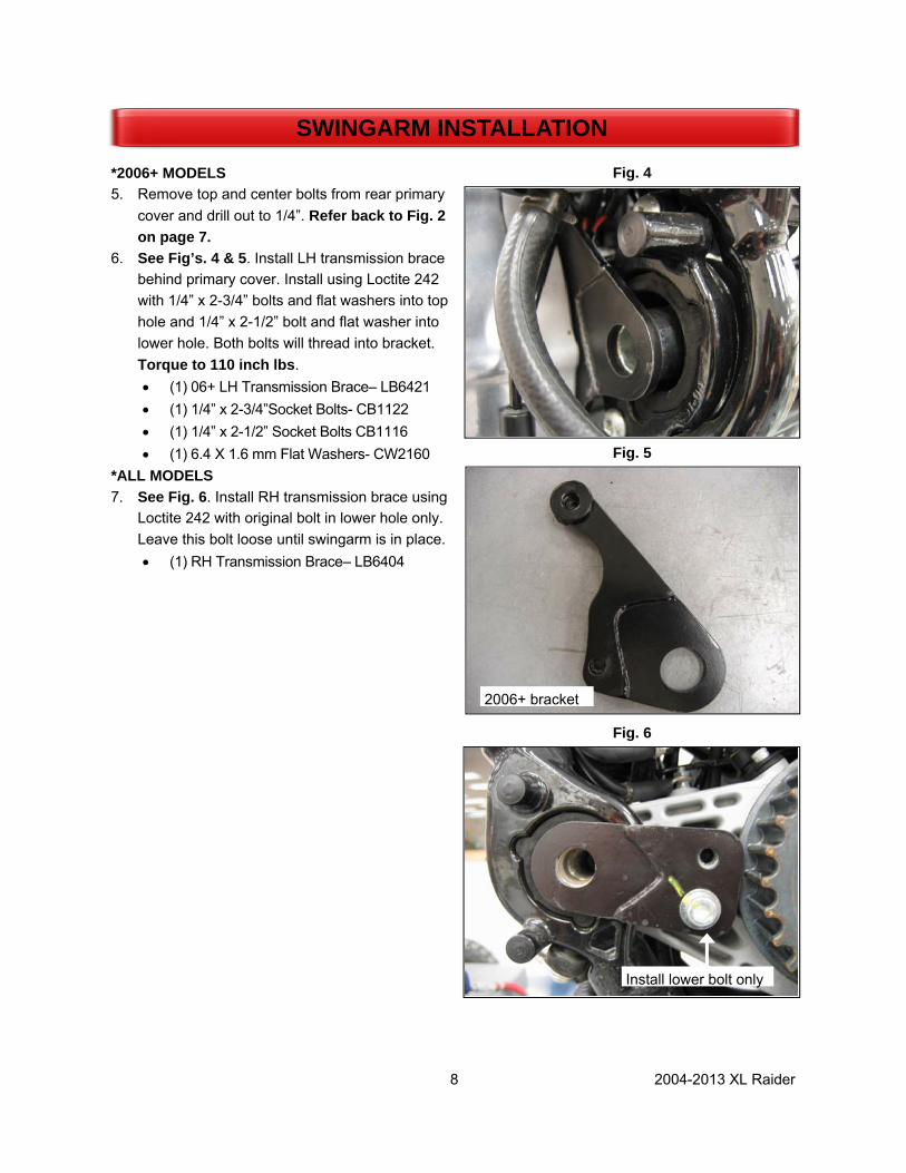
*2006+ MODELS 5. Remove top and center bolts from rear primary
cover and drill out to 1/4”. Refer back to Fig. 2 on page 7.
6. See Fig’s. 4 & 5. Install LH transmission brace behind primary cover. Install using Loctite 242 with 1/4” x 2-3/4” bolts and flat washers into top hole and 1/4” x 2-1/2” bolt and flat washer into lower hole. Both bolts will thread into bracket. Torque to 110 inch lbs. • (1) 06+ LH Transmission Brace– LB6421 • (1) 1/4” x 2-3/4”Socket Bolts- CB1122 • (1) 1/4” x 2-1/2” Socket Bolts CB1116 • (1) 6.4 X 1.6 mm Flat Washers- CW2160
*ALL MODELS 7. See Fig. 6. Install RH transmission brace using
Loctite 242 with original bolt in lower hole only. Leave this bolt loose until swingarm is in place. • (1) RH Transmission Brace– LB6404
SWINGARM INSTALLATION
Fig. 4
Fig. 5
Fig. 6
2006+ bracket
Install lower bolt only

9 2004-2013 XL Raider
8. Slide swingarm over transmission braces and line up holes on both sides. 9. Apply Loctite 242 to H-D pivot pins and install into swingarm. Torque to 70 ft. lbs. Be sure the swin-
garm moves freely up and down. Place a jack stand under swingarm for support. Torque RH trans-mission brace lower bolt to 33 ft. lbs.
SWINGARM INSTALLATION
Fig. 7
Swingarm installed
10 2004-2013 XL Raider
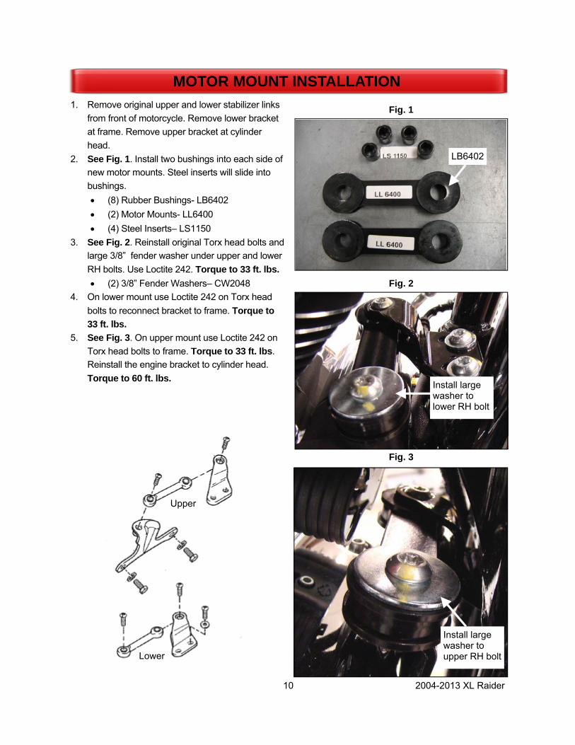
1. Remove original upper and lower stabilizer links from front of motorcycle. Remove lower bracket at frame. Remove upper bracket at cylinder head.
2. See Fig. 1. Install two bushings into each side of new motor mounts. Steel inserts will slide into bushings. • (8) Rubber Bushings- LB6402 • (2) Motor Mounts- LL6400 • (4) Steel Inserts– LS1150
3. See Fig. 2. Reinstall original Torx head bolts and large 3/8” fender washer under upper and lower RH bolts. Use Loctite 242. Torque to 33 ft. lbs. • (2) 3/8” Fender Washers– CW2048
4. On lower mount use Loctite 242 on Torx head bolts to reconnect bracket to frame. Torque to 33 ft. lbs.
5. See Fig. 3. On upper mount use Loctite 242 on Torx head bolts to frame. Torque to 33 ft. lbs. Reinstall the engine bracket to cylinder head. Torque to 60 ft. lbs.
MOTOR MOUNT INSTALLATION
Fig. 1
Fig. 2
Fig. 3
LB6402
Install large washer to lower RH bolt
Install large washer to upper RH bolt
Upper
Lower

11 2004-2013 XL Raider
1. See Fig. 1. Install adjuster bolts and jam nuts to each side of swingarm as shown. Bolt head will face front of bike. Thread bolt into swin-garm just enough to thread nut on backside. • (2) Adjuster Bolt M10 X 100 (CB1608) • (2) Jam Nut M10 (CN1912)
2. Support swingarm with jack stands. 3. See Fig. 2. Attach differential assembly to
swingarm as shown.
• (4) Bolt M12 X 30 (CB1987) • (4) Nut M12 (CN1917)
NOTE: Swingarm plates will sit above differen-tial plates Slide differential as far forward as possible. Set jack stands under axle tubes. 4. Tighten pinch block hardware just enough to
allow differential to slide on swingarm plates. 5. See Fig. 3. Remove upper, lower and rear
housing plates. 6. See Fig. 3. Carefully slide belt over front and
rear pulleys. 7. Reinstall housing plates with original hardware
using Loctite 242. Install all hardware before tightening. Torque hardware to 17 ft. lbs.
DIFFERENTIAL INSTALLATION
Fig. 2
Fig. 1
Fig. 3
Jam nut
Adjuster
Swingarm plate on top
Differential plate
Remove plates
Install belt

12 2004-2013 XL Raider
NOTE: Once proper belt tracking is achieved the shocks will need to be removed. 1. Temporarily install shocks to trike as shown. 2. See Fig. 1. Install spacer between shock and
frame on upper RH side Use 1/2” x 2-3/4” bolt and 14mm flat washer. • (1) RH Shock Spacer– S001941 • (1) 1/2” x 2-3/4” Hex Bolt– CB1427 • (1) 14mm Flat Washer– CW2155
3. See Fig. 2. RH Shock will mount to threaded hole on RH axle tube with shoulder bolt and flat washer. • (1) 1/2” 1-1/2” Shoulder Bolt– CB1426 • (1) 14mm Flat Washer– CW2155
4. See Fig. 3. Install LH shock as shown using original H-D hardware.
DIFFERENTIAL INSTALLATION
Fig. 2
Fig. 3
Fig. 1
Spacer
Thread bolt into axle tube
RH Shock
RH Shock
LH Shock
CB1426
1/2” Shoulder
3/8” Threads

13 2004-2013 XL Raider
1. Using adjuster bolts, push differential assembly back until belt has about 3/8” slack with 10 lbs. pressure at midpoint of bottom run. Measure between swingarm and differential to ensure that both sides are equal distance.
2. Rotate pulleys forward for at least 3 revolutions of rear pulley by pulling backwards on bottom run of belt. Pull belt straight back to get an ac-curate reading. Check that belt is not climbing flanges on rear pulley. The adjusters may need to be moved in or out from side to side to achieve proper tracking.
3. Torque rear differential plate bolts to 75 ft. lbs. 4. See Fig. 1. Once proper tracking is obtained,
re-check belt tension. The correct deflection is 5/16” – 3/8” with 10 lbs. of pressure ap-plied.
5. Torque and mark (4) “Swingarm to Differen-tial Bolts” to 93 ft. lbs. using 16mm shallow socket and 18mm wrench.
6. Adjust belt tension by loosening rear plate bolts and moving adjusters same amount on both sides. If any adjustment is made you must re-check belt tracking.
NOTE: Be sure belt is not climbing up side of the pulley or squeaking as belt is rotated. 8. After all adjustments are made, tighten adjuster
lock nuts. 9. Remove rear shocks for body installation. NOTE: Body will interfere with shocks during installation if they are left in place. 10. See Fig. 2. Chrome sprocket cover will need to
be modified before reinstalling. Trim 3/16” from inner shaft to allow clearance with new trans-mission bracket in place.
11. Reinstall cover using two 1/4” washers behind the lower mounting hole to achieve proper clearance with front pulley. Chrome exhaust bracket will also be reinstalled Use original mounting hardware. • (2) 1/4” Flat Washer– CW2005
NOTE: Torque 1/4” bolt to 110 in. lbs. Torque 3/8” bolt to 33 ft. lbs.
BELT TENSIONING
Fig. 1
Drive belt deflection
Fig. 2
Trim 3/16”

14 2004-2013 XL Raider
1. See Fig’s 1 thru 3. Install differential brace to trike as shown adjusting as necessary for fit-ment. Attach to housing and swingarm using the following hardware. • (1) M10 X 35 Bolt- CB1607 • (1) M8 X 40 Bolt- CB1975 • (1) Conical Spacer- S001784 • (1) M10 Lock Nut- CN3049
2. Tighten jam nuts on differential brace after final adjustments are made.
3. Torque front differential housing brace bolt to
17 ft. lbs. 4. Torque differential brace bolt (swingarm side) to
36 ft. lbs.
STABILIZER INSTALLATION
Fig. 1
Fig. 2
Install spacer in housing
Fig. 3
15 2004-2013 XL Raider
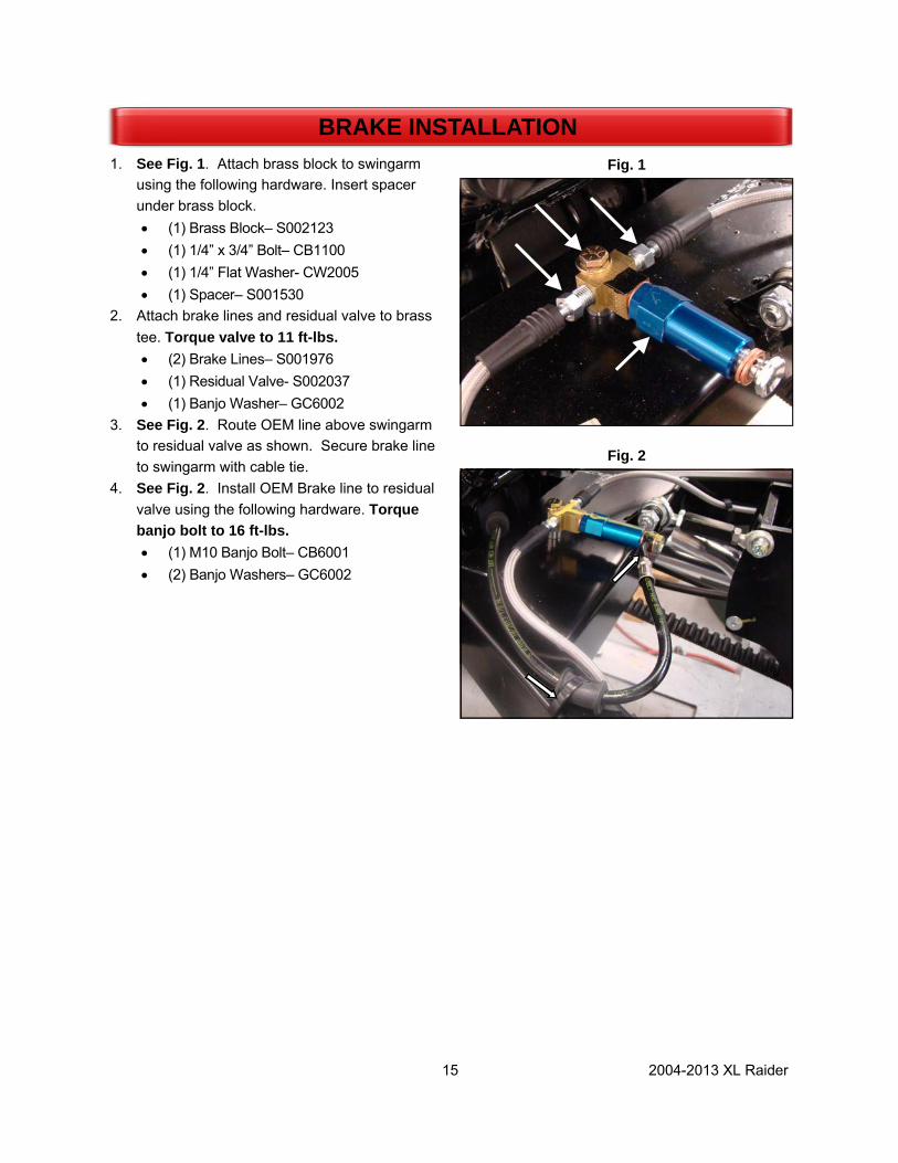
1. See Fig. 1. Attach brass block to swingarm using the following hardware. Insert spacer under brass block. • (1) Brass Block– S002123 • (1) 1/4” x 3/4” Bolt– CB1100 • (1) 1/4” Flat Washer- CW2005 • (1) Spacer– S001530
2. Attach brake lines and residual valve to brass tee. Torque valve to 11 ft-lbs. • (2) Brake Lines– S001976 • (1) Residual Valve- S002037 • (1) Banjo Washer– GC6002
3. See Fig. 2. Route OEM line above swingarm to residual valve as shown. Secure brake line to swingarm with cable tie.
4. See Fig. 2. Install OEM Brake line to residual valve using the following hardware. Torque banjo bolt to 16 ft-lbs. • (1) M10 Banjo Bolt– CB6001 • (2) Banjo Washers– GC6002
BRAKE INSTALLATION
Fig. 2
Fig. 1
16 2004-2013 XL Raider
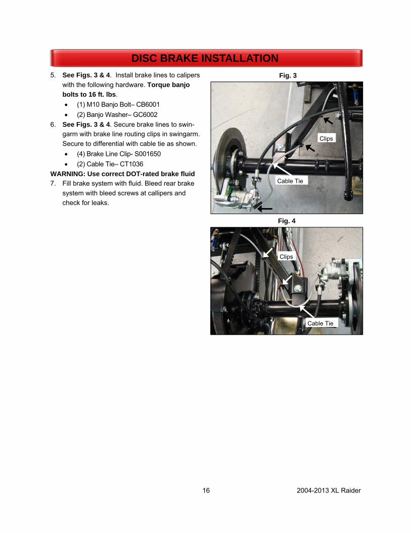
5. See Figs. 3 & 4. Install brake lines to calipers with the following hardware. Torque banjo bolts to 16 ft. lbs. • (1) M10 Banjo Bolt– CB6001 • (2) Banjo Washer– GC6002
6. See Figs. 3 & 4. Secure brake lines to swin-garm with brake line routing clips in swingarm. Secure to differential with cable tie as shown. • (4) Brake Line Clip- S001650 • (2) Cable Tie– CT1036
WARNING: Use correct DOT-rated brake fluid 7. Fill brake system with fluid. Bleed rear brake
system with bleed screws at callipers and check for leaks.
Fig. 3
DISC BRAKE INSTALLATION
Cable Tie
Clips
Clips
Fig. 4
Cable Tie

17 2004-2013 XL Raider
Park Brake Assembly 1. See Fig. 1. Install park brake cables to caliper
brackets. Secure cable to bracket with cir-clip provided on cables.
2. See Fig. 2. Attach park brake bracket with RH body mount bracket to trike using original foot peg mounting holes using the following hard-ware. Body mount will go on outside of park brake bracket. Spacers will go over bolts on inside of bracket. Torque to 33 ft. lbs. • (1) Park Brake Bracket– LB6412 • (1) RH Body Mount– LB6408 • (2) Short Spacers– LS6404 • (2) 3/8” x 2” Bolt– CB1255 • (2) 3/8” Flat Washers– CW2015
3. See Fig. 3. LH body mount will use longer spacers with the following hardware. Brake line clamp will be installed on lower bolt. • (1) LH Body Mount– LB6407 • (2) Long Spacers– LS6405 • (2) 3/8” x 2” Bolt– CB1255 • (2) 3/8” Flat Washers– CW2015 • (1) Brake Line Clamp– GC0112
PARK BRAKE INSTALLATION
Brake line clamp
RH body mount bracket
Park brake bracket Short spacers
LH body mount bracket
Fig. 3
Fig. 2
Fig. 1

18 2004-2013 XL Raider
4. See Fig. 4. Remove snap ring from one side of pin on park brake lever. Hold handle on its side and push release button at end of handle to allow pin to slide out. • (1) Park Brake Lever– GB1099M
5. See Fig. 4. Place hand brake within park brake bracket, ensuring ratchet is secure on cross brace. Attach with pin and snap ring.
6. See Fig. 4. Attach park brake cable pulling bracket (LB1294) to hand brake using clevis pin and cotter key.
7. See Fig. 5. Route long LH park brake cable above differential and down RH side of hous-ing. Attach to top of differential housing with clamp as shown. • (1) 1/2” Clamp– S001654 • (1) M8 x 30 Button Head Bolt– CB1929
8. See Fig. 5. Route short RH cable under differ-ential and into park brake bracket. Attach LH and RH cables together with clamp to lower axle tube bolt as shown. Check for proper clearance with other components. • (1) 3/4” Clamp– GC0108
9. See Fig. 6. Attach park brake cables to bracket as shown using nuts and washers provided on cables. Use one nut and washer on each side of bracket
10. See Fig. 6. Thread one 5/16” NF nut onto each brake cable. Place threaded end of brake ca-bles through holes in cable pulling bracket. Thread a second nut onto each brake cable on the front of the bracket. • (4) 5/16” Nuts– CN3009
11. Ensure park brakes are properly set up, adjust park brake nuts on both sides. Brakes should hold within 3-4 clicks on lever.
PARK BRAKE INSTALLATION
Attach cables to park brake bracket
Attach cable ends to pulling bracket with jam nuts
Fig. 5
Fig. 6
Attach LH cable to housing
Secure with clamp
Fig. 4
19 2004-2013 XL Raider
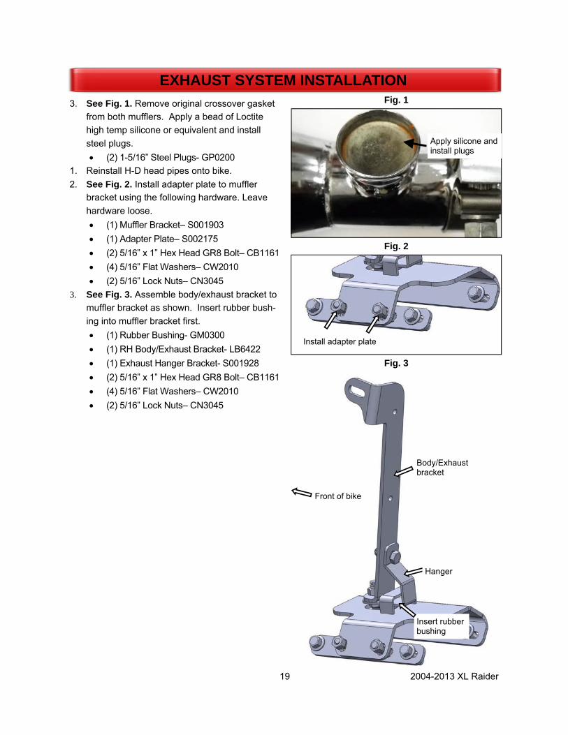
3. See Fig. 1. Remove original crossover gasket from both mufflers. Apply a bead of Loctite high temp silicone or equivalent and install steel plugs. • (2) 1-5/16” Steel Plugs- GP0200
1. Reinstall H-D head pipes onto bike. 2. See Fig. 2. Install adapter plate to muffler
bracket using the following hardware. Leave hardware loose. • (1) Muffler Bracket– S001903 • (1) Adapter Plate– S002175 • (2) 5/16” x 1” Hex Head GR8 Bolt– CB1161 • (4) 5/16” Flat Washers– CW2010 • (2) 5/16” Lock Nuts– CN3045
3. See Fig. 3. Assemble body/exhaust bracket to muffler bracket as shown. Insert rubber bush-ing into muffler bracket first. • (1) Rubber Bushing- GM0300 • (1) RH Body/Exhaust Bracket- LB6422 • (1) Exhaust Hanger Bracket- S001928 • (2) 5/16” x 1” Hex Head GR8 Bolt– CB1161 • (4) 5/16” Flat Washers– CW2010 • (2) 5/16” Lock Nuts– CN3045
EXHAUST SYSTEM INSTALLATION Fig. 1
Apply silicone and install plugs
Fig. 2
Fig. 3
Install adapter plate
Insert rubber bushing
Hanger
Body/Exhaust bracket
Front of bike

20 2004-2013 XL Raider
4. See Fig. 3. Install mufflers to bracket using original mounting hardware.
5. Install Lehman pipes into H-D mufflers. Short pipe will go on RH muffler (rear head pipe) and long pipe will go on LH muffler (front head pipe). • (1) Short RH Exhaust Pipe-LP6406 • (1) Long LH Exhaust Pipe– LP6407
6. Use Loctite high temp silicone or equivalent in pipe where it slides over H-D head pipe.
7. See Fig. 4. Place exhaust clamps onto exhaust pipes. Install Lehman pipes over H-D head pipes. • (2) Exhaust Clamps– GC1015
8. Leave all exhaust pipes and brackets loose. Exhaust will be completed once body has been installed on trike.
9. See Fig. 5. Install RH body/exhaust bracket to outside of RH H-D frame rail using the following hardware. • (1) RH Body/Exhaust Bracket-LB6422 • (1) 5/16” x 1-1/2” Bolt– CB1170 • (2) 5/16” Flat Washers– CW2010 • (1) 5/16” Lock Nuts– CN3045
EXHAUST SYSTEM INSTALLATION Fig. 3
Fig. 4
Install extension pipes to head pipes
Fig. 5
Exhaust Bracket
RH frame rail
Front of bike

21 2004-2013 XL Raider
1. See Fig. 1. Attach rubber bumper to body sup-port bracket using 1/2”bolt. Place a 1/2” washer on both sides of rubber bumper and secure with thin 1/2” lock nut. Place a 1/2” jam nut on bolt and thread bolt into bracket until distance be-tween top of bracket and bottom of bumper is 1-1/4”. Secure jam nut to bracket. • (1) Rubber Bumper– LS6407 • (1) Top Body Support Bracket– LS6406 • (1) 1/2” x 2 1/2” Bolt– CB1416 • (2) 1/2” Washers– CW2025 • (1) 1/2” Thin Lock Nut– CN3250-0 • (1) 1/2” Nut– CN3025
2. See Fig. 2. Install top body support (LS6406) to H-D frame using the following hardware. Leave bolts loose. • (2) 5/16” x 1-3/4” Bolts- CB1175 • (2) 5/16” Flat Washers– CW2010 • (2) 5/16” Lock Washers– CW2045
3. See Fig. 3. Install rear LH body mount bracket to LH H-D frame rail using the following hard-ware. This bracket should also be left loose until body is mounted. RH body/exhaust bracket (LB6422) should already be in place from ex-haust setup. • (1) LH Body Mount Bracket– LB6410 • (1) 5/16” x 1-1/2” Bolts– CB1170 • (2) 5/16” Flat Washers– CW2010 • (1) 5/16” Lock Nuts– CN3045
BODY MOUNT INSTALLATION
1-1/4” Lock nut
Jam nut
Fig. 1
Fig. 2
Fig. 3

22 2004-2013 XL Raider
NOTE: ECM remounting is done on 2004-2009 models only. 1. See Fig. 1.Install U-bolts around center section
of body support and through rear mounting holes of mounting bracket; hand-tighten U-bolts with ¼” lock nuts. • (2) U-Bolts– CB6201 • (2) 1/4” Lock Nuts– CN3040
2. See Fig. 2. Install ECM to mounting bracket using the following hardware. • (4) 1/4” x 1-1/2” Bolts– CB1095 • (4) 1/4” Lock Nuts– CN3006
3. See Fig. 3 . Rotate rear body support arm up-ward into position; ECM bracket tab should be centered behind support to prevent bracket from falling.
ECM MOUTNING 2004-2009 MODELS
ECM bracket tab sits behind body mount
Fig. 1
Fig. 2
Fig. 3

23 2004-2013 XL Raider
1. See Fig. 1. Remove base from turn signals and mount to body in designated holes using the following hardware. • (2) Turn Signals– OEM • (2) 5/16” x 1-1/4” Bolts– CB1165 • (2) 5/16” Lock Washers– CW2045 • (2) 5/16” Flat Washers– CW2010
2. See Fig. 2. Install door seal to body. Place seal against edge of trunk opening with seam at cen-ter of bottom edge. assembly to trunk door.
• (3.75’) Trunk Door Seal– S001688 3. See Fig. 3.. Install license plate bracket to
trunk door. Use tapered rubber spacer between door and bracket. Attach to door using the up-per and RH holes in bracket. Use stainless washers and lock nuts against bracket. Install rubber washers inside trunk. • (1) License Plate Bracket– S001039 • (2) 1/4” x 1-1/2” Button Head- CB1096 • (2) 6.4mm x 18mm Washer- CW2154 • (2) 1/4” x 3/4” Rubber Washer- FG1002 • (2) 1/4” SS Flat Washers- CW2006 • (2) 1/4” Lock Nut- CN3040
4. See Fig 3. Install license plate light to bracket using bolts, washers and nuts. • (2) 1/4” x 3/4” Button Head– CB1084 • (2) 1/4” Flat Washers– CW2006 • (2) 1/4” Acorn Nuts– CN3070
5. See Fig 3. Route license plate wire through LH hole in bracket and door. Apply silicone around wire where it enters bracket to prevent leaks.
6. See Fig 3. Install latch assembly to door. Do not over tighten. • (1) Trunk Latch Assembly–S001593
BODY PREPARATION
Fig. 1
Fig. 3
Install latch to door
Attach light to bracket
Route wire through bracket
Fig. 2
Place seal against door opening
Seal seam

24 2004-2013 XL Raider
NOTE: Do not over tighten taillight mounting hardware. Damage to housing may occur. 1. See Fig 1 & 2. Mount taillight assemblies to
body with gaskets. Attach ground wire to stud with flange nut after taillight mounting hardware is installed. • (2) Taillight Assembly-S002204 • (2) Gaskets– BG0200 • (4) 1/4” Flat Washer– CW2006 • (4) Lock washer– Provided with light • (4) Nut– Provided with light • (2) 1/4” Flange Nut– CN3007
2. See Fig’s 3 & 4. If required- Install female terminals and male connectors to taillight wiring Use appropriate tool for crimping terminals to wires. (Mac Tools– TCT1028).
3. See Fig’s 3 & 4. Inspect crimps before install-ing into connector. Distortion should be mini-mal.
BODY PREPARATION Fig. 1
Fig. 4
Fig. 3
Wire core crimp
Insulation crimp Female Terminal
1
2
3
Attach ground wire to stud
Fig. 2

25 2004-2013 XL Raider
1. See Fig. 1. Install door hinges to body using 8/32” oval-head screws. • (2) Door Hinges– GH0910 • (4) 8/32” x 5/8” Oval Screws– CS4021-1
2. See Fig. 2. Install door hinge mount clips to door using 6/32” x 1/4” machine screws. • (2) Hinge Mount Clips– GH0912 • (4) 6/32” x 1/4” Screws– CS4073
3. Install door to body by connecting door hinges to body hinges; hinges will snap to-gether. Perform initial fitment test.
4. See Fig. 3. Hinges may be adjusted from side to side, in or out and up and down
DOOR INSTALLATION
Fig. 1
Fig. 2
Fig. 3
Use lower adjust-ment screw to move door in or out
Use top adjustment screw to move door up or down
Loosen set screw to adjust side to side
Attach plates to door

26 2004-2013 XL Raider
5. Test door seal by closing door with a strip of pa-per at various locations around door. Door seals properly when paper has significant drag.
6. See Fig. 4. Install stop cable to one hinge as-sembly. Secure with crimps (on each end. • Cable– CC0089 • (2) Cable Crimps– CC1900
DOOR INSTALLATION
Install cable through hinge
Fig. 4

27 2004-2013 XL Raider
NOTE: Use appropriate tool for crimping terminals to wires. (Mac Tools– TCT1028, Blue Point– PWC47 or H-D 41609). 1. See Fig. 2. Inspect crimps before installing connector. Distortion should be minimal. 2. Install trike wire harness (S001922) to body clips on underside of body. Route Purple/Black turn sig-
nal wiring to LH fender. Route Brown/Black turn signal wiring to RH Fender. 3. Trim wiring from each OEM turn signal leaving 5 1/2” of wire. 4. See Fig’s. 1 & 2. Install male terminals to turn signals wires. Install turn signal terminals into 2 pin fe-
male connector. 5. Drill hole in rear trunk floor for licence plate wiring. Route wiring through trunk floor and install female
terminals and connectors. Match Red wire (+) from light to Red wire on Body. Match Black wire (-) from light to Black wire on body. Plug license plate light into harness. Seal harness through trunk floor with silicone.
BODY WIRING
Wire core crimp
Insulation crimp
Fig. 1 Fig. 2 Male terminal

28 2004-2013 XL Raider
1. Lay down top body support so that it is level with frame.
2. See Fig. 1. Slide body around RH bracket and up over HD frame. Install seat center post with sup-plied 5/16” fender washer on bolt head. Leave this bolt loose. Body will sit under mounting tab. • (1) 5/16” Fender Washer– CW2109
3. Raise top support back up and let body rest on it. 4. Attach body to front mounts using the following
hardware. Leave hardware loose. • (2) 1/4” x 1-1/2” Button Head- CS4031 • (4) 1/4” Flat Washers– CW2005 • (2) 1/4” Lock Nut– CN3040
5. Install shocks. Torque LH shock bolts to 45 ft. lbs. Torque RH upper shock bolt to 45 ft. lbs. Torque lower RH shock bolt to 23 ft. lbs.
NOTE: Adjust shocks to middle setting 6. Set bike on jack stands to achieve proper ride
height. 7. Measure body from side to side and front to back.
Top body support may be adjusted to move body up or down. Be sure to leave enough clearance for mufflers on back of body. Exhaust will still be loose and need to be held in place to check clearance.
8. See Fig. 2. Verify there is at least a 1/4” gap be-tween the body and chrome belt cover on RH side.
9. See Fig. 3. Once body is in place, push LH bracket flush against body and tighten bracket to frame. Using bracket as a guide drill two 1/4” holes through trunk wall. Attach using the following hard-ware. Bolt head, fender washer and rubber washer will go inside trunk. • (2) 1/4” x 1” Button Head- CB1086 • (4) 1/4” Fender Washers– CW2108 • (2) 1/4” Rubber Washers– FG1002 • (2) 1/4” Flat Washers– CW2005 • (2) 1/4” Lock Nut– CN3040
BODY INSTALLTION
Fig. 2
Fig. 1
Fig. 3
LH body bracket hardware inside trunk
Minimum 1/4’ gap between body and cover

29 2004-2013 XL Raider
10. See Fig. 4. Before drilling RH bracket holes, push exhaust away from differential hous-ing. Exhaust pipes should be at least 1” away from housing (make sure pipes are straight). A wedge can be used to hold pipes in place while you tighten bracket to frame and drill two 1/4” holes. Attach to body using the following hardware. • (2) 1/4” x 1” Button Head- CB1086 • (4) 1/4” Fender Washers– CW2108 • (2) 1/4” Rubber Washers– FG1002 • (2) 1/4” Flat Washers– CW2005 • (2) 1/4” Lock Nut– CN3040
11. See Fig. 5. Install exhaust support bracket between original bracket on belt cover and original clamp on rear head pipe. Use original bolt and acorn nut to attach bracket to clamp. Use bolt and lock nut to attach support bracket to belt cover bracket. • (1) Exhaust Bracket- S001907 • (1) 3/8” x 3/4” Button Head- CB1232 • (1) 3/8” Lock Nut- CN3050
12. Before tightening rest of exhaust, make sure that there is proper clearance along both pipes. Rear head pipe may need to be pulled away from park brake bracket.
13. Tighten all exhaust clamps and nuts. 14. Reinstall all HD heat shields along with Leh-
man heat shield (GS914) to lower pipe. 15. Tighten seat center post, front bracket bolts,
and top body support jam nut. 16. Install passenger footpads using the following
hardware. • (6) 1/4” Flat Washers– CW2005 • (6) 1/4” Lock Nuts– CN3040
17. See Fig. 6. Set seat in place and center it on trike. Mark rear hole and drill using a 31/64” bit. Install 1/4” well nut into body. Install seat using the following hardware. • (1) 1/4” Well Nut– CN3400 • (1) 1/4” x 1” Phillips Screw– CS4080
BODY INSTALLTION
Center seat on body and drill hole
Fig. 4
Fig. 6
Exhaust support bracket
Fig. 5
Original Hardware

30 2004-2013 XL Raider
1. See Fig. 1. Once body is in place and se-cure, install support bracket to motorcycle frame using the following hardware. • (1) Support Bracket- S001942 • (1) 5/16” x 1-1/2” Bolt– CB1170 • (2) 5/16” Flat Washers– CW2010 • (1) 5/16” Lock Nut– CN3045 • (1) 1/4” U-Bolt– CB6201 • (2) 1/4” Flat Washers– CW2005 • (2) 1/4” Lock Nuts– CN3040
2. See Fig. 2. Grab handles will be installed on body, next to passenger section of seat.
3. Evenly locate grab handles on body and mark for drilling. Drill holes using 1/4” drill bit.
CAUTION: Make sure LH rear hole does not interfere with front trunk wall when locating handles. 4. Place rubber standoff (S001701) between
grab handle and body. 5. Install grab handles to body using the fol-
lowing hardware. • (2) Grab Handles– S001035 • (4) 5/16” x 1” Socket Bolts- CB1159 • (4) 5/16” Lock Washers– CW2047 • (4) 5/16” Fender Washers–CW2109
GRAB HANDLE INSTALLATION
Front of trike
Even spacing from center of body
Fig. 1
Attach support bracket to frame and top support
Fig. 2

31 2004-2013 XL Raider
1. Install reflectors to body. • (4) Reflectors– S001045
2. See Fig. 1. Two red reflectors will be cen-tered on side of fenders and a 1/4” up from edge. They should be located directly above wheel center cap on body.
3. Last two red reflectors will be centered 3” below rear taillights on body.
4. Install Lehman and Raider badges to body as shown. • (1) Lehman Badge– GB1327 • (1) Raider Badge– GB1323
5. Install wheels. Torque wire wheel lug nuts to 75 ft.-lbs. and aluminum wheel lug nuts to 85 ft.-lbs.
CAUTION: Do not use an impact when install-ing lug nuts.
FINAL ASSEMBLY
Fig. 1
Fig. 2
32 2004-2013 XL Raider
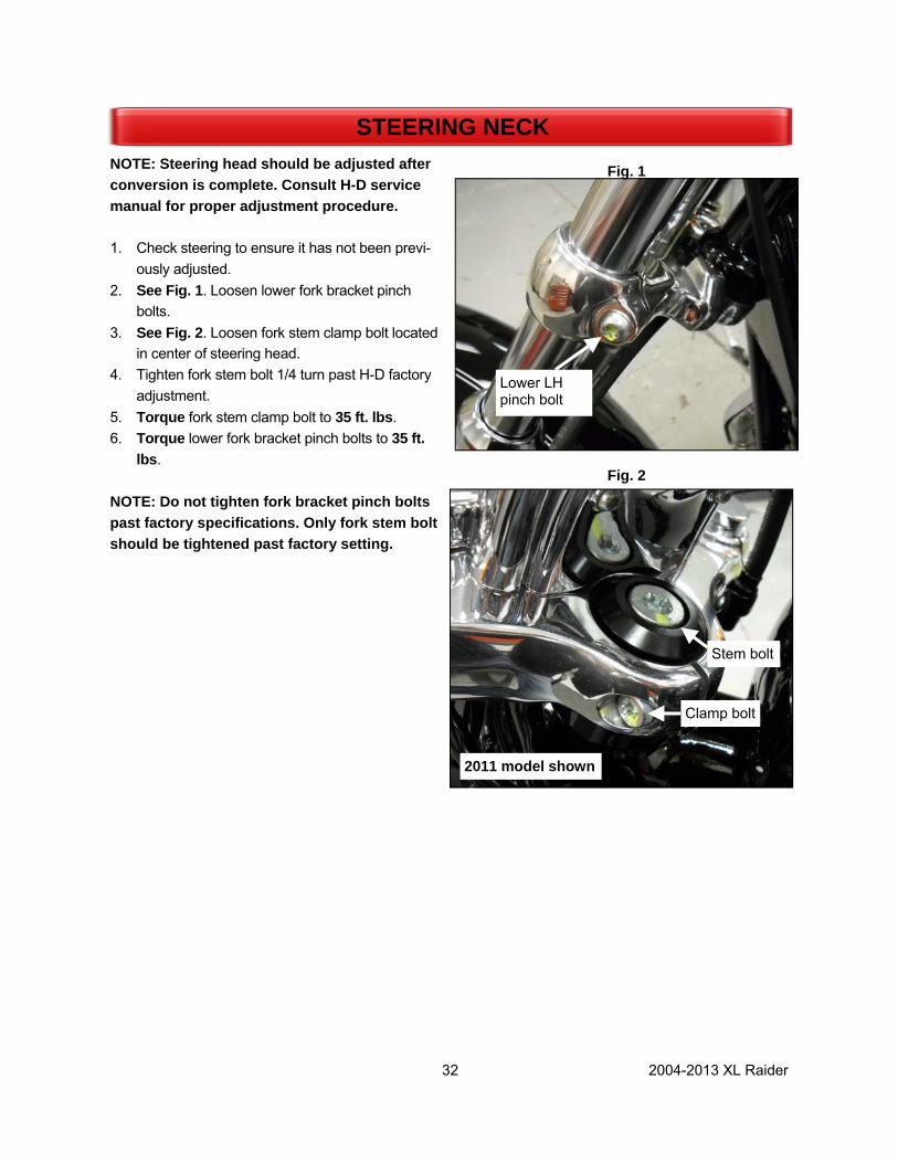
NOTE: Steering head should be adjusted after conversion is complete. Consult H-D service manual for proper adjustment procedure. 1. Check steering to ensure it has not been previ-
ously adjusted. 2. See Fig. 1. Loosen lower fork bracket pinch
bolts. 3. See Fig. 2. Loosen fork stem clamp bolt located
in center of steering head. 4. Tighten fork stem bolt 1/4 turn past H-D factory
adjustment. 5. Torque fork stem clamp bolt to 35 ft. lbs. 6. Torque lower fork bracket pinch bolts to 35 ft.
lbs. NOTE: Do not tighten fork bracket pinch bolts past factory specifications. Only fork stem bolt should be tightened past factory setting.
STEERING NECK
Stem bolt
Clamp bolt
2011 model shown
Fig. 1
Fig. 2
Lower LH pinch bolt

33 2004-2013 XL Raider
FINAL TRIKE INSPECTION
Reflectors installed Good Rework
Light operation □ □
Park brake operation □ □
Engine/Transmission oil levels □ □
Belt tension 5/16”-3/8” □ □
Wheel torque 85 ft-lbs. (75 ft. lbs-wire) □ □
Rear tire pressure 26 psi □ □
Front tire pressure—Refer to OEM psi □ □
Trunk clean and dry □ □
Trunk door seals and operates smooth □ □
Shocks set at mid setting □ □
Heat shields installed □ □
Side covers installed □ □
Lehman/Raider badges installed □ □
No paint defects □ □
Warranty/Owners manual with bike □ □
34 2004-2013 XL Raider
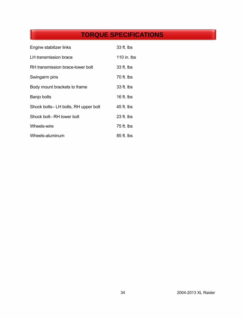
Engine stabilizer links 33 ft. lbs
LH transmission brace 110 in. lbs
RH transmission brace-lower bolt 33 ft. lbs
Swingarm pins 70 ft. lbs
Body mount brackets to frame 33 ft. lbs
Banjo bolts 16 ft. lbs
Shock bolts– LH bolts, RH upper bolt 45 ft. lbs
Shock bolt– RH lower bolt 23 ft. lbs
Wheels-wire 75 ft. lbs
Wheels-aluminum 85 ft. lbs
TORQUE SPECIFICATIONS
35 2004-2013 XL Raider
HARDWARE
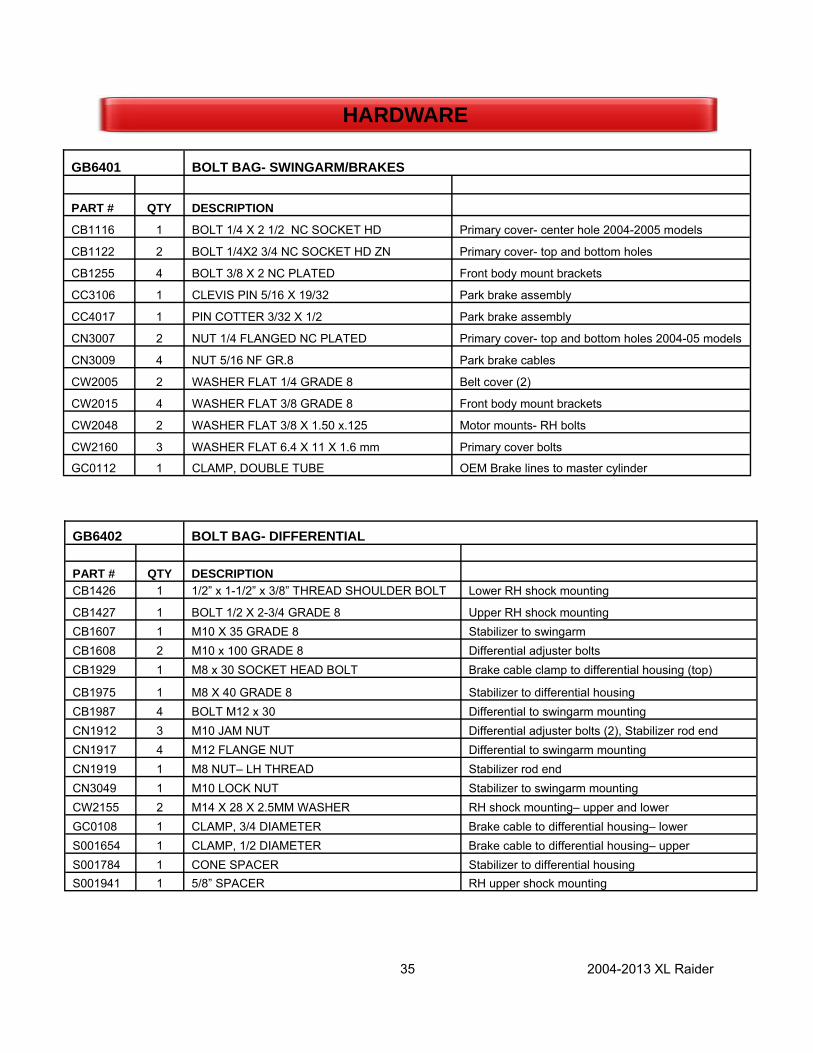
GB6401 BOLT BAG- SWINGARM/BRAKES
PART # QTY DESCRIPTION
CB1116 1 BOLT 1/4 X 2 1/2 NC SOCKET HD Primary cover- center hole 2004-2005 models
CB1122 2 BOLT 1/4X2 3/4 NC SOCKET HD ZN Primary cover- top and bottom holes
CB1255 4 BOLT 3/8 X 2 NC PLATED Front body mount brackets
CC3106 1 CLEVIS PIN 5/16 X 19/32 Park brake assembly
CC4017 1 PIN COTTER 3/32 X 1/2 Park brake assembly
CN3007 2 NUT 1/4 FLANGED NC PLATED Primary cover- top and bottom holes 2004-05 models
CN3009 4 NUT 5/16 NF GR.8 Park brake cables
CW2005 2 WASHER FLAT 1/4 GRADE 8 Belt cover (2)
CW2015 4 WASHER FLAT 3/8 GRADE 8 Front body mount brackets
CW2048 2 WASHER FLAT 3/8 X 1.50 x.125 Motor mounts- RH bolts
CW2160 3 WASHER FLAT 6.4 X 11 X 1.6 mm Primary cover bolts
GC0112 1 CLAMP, DOUBLE TUBE OEM Brake lines to master cylinder
GB6402 BOLT BAG- DIFFERENTIAL PART # QTY DESCRIPTION CB1426 1 1/2” x 1-1/2” x 3/8” THREAD SHOULDER BOLT Lower RH shock mounting
CB1427 1 BOLT 1/2 X 2-3/4 GRADE 8 Upper RH shock mounting CB1607 1 M10 X 35 GRADE 8 Stabilizer to swingarm CB1608 2 M10 x 100 GRADE 8 Differential adjuster bolts CB1929 1 M8 x 30 SOCKET HEAD BOLT Brake cable clamp to differential housing (top)
CB1975 1 M8 X 40 GRADE 8 Stabilizer to differential housing CB1987 4 BOLT M12 x 30 Differential to swingarm mounting CN1912 3 M10 JAM NUT Differential adjuster bolts (2), Stabilizer rod end CN1917 4 M12 FLANGE NUT Differential to swingarm mounting CN1919 1 M8 NUT– LH THREAD Stabilizer rod end CN3049 1 M10 LOCK NUT Stabilizer to swingarm mounting CW2155 2 M14 X 28 X 2.5MM WASHER RH shock mounting– upper and lower GC0108 1 CLAMP, 3/4 DIAMETER Brake cable to differential housing– lower S001654 1 CLAMP, 1/2 DIAMETER Brake cable to differential housing– upper S001784 1 CONE SPACER Stabilizer to differential housing S001941 1 5/8” SPACER RH upper shock mounting
36 2004-2013 XL Raider
HARDWARE
GB6403 BOLT BAG BODY/EXHAUST 04+ XL RAIDER PART # QTY DESCRIPTION CB1084 2 BOLT, 1/4 X 3/4 NC BUTTON HEAD SS License plate light to bracket CB1086 4 BOLT, 1/4X 1 NC BUTTON HEAD SS Rear body mounts LH & RH
CB1160 2 BOLT, 5/16 X 1 NC PLATED Exhaust bracket (2) CB1165 2 BOLT, 5/16 X 1 1/4 NC PLATED Turn signals (2)
CB1170 3 BOLT, 5/16 X 1 1/2 NC PLATED LH rear body mount (1), RH rear body mount (1) Top support bracket (1)
CB1175 2 BOLT, 5/16 X 1 3/4 NC PLATED Top body support bracket CB1232 1 BOLT, 3/8 X 3/4 NC BUTTON HEAD Exhaust support bracket CB1416 1 BOLT, 1/2 X 2 1/2 NC FULL THREAD Top body support CB6201 1 U-BOLT, 1/4 x2 Top body support to frame bracket CN3025 1 NUT, 1/2 NC PLATED Top body support
CN3040 16 NUT, LOCK 1/4 NC PLATED Foot pad (6), front body mount (2), rear body mount (4), license plate bracket (2), U-bolt– top body support (2)
CN3045 6 NUT, LOCK 5/16 NC PLATED Exhaust bracket (3), rear body mount brackets (2) top body support (1)
CN3050 1 NUT, LOCK 3/8 NC PLATED Exhaust support bracket CN3070 2 NUT, ACORN 1/4 License plate light to bracket CN3250-0 1 NUT, JAM NYLOCK 1/2 NC Top body support CN3400 1 NUT, WELL 1/4 Seat mounting CS4031 2 SCREW, BH SK CAP 1/4X1.5 Front body mount CS4080 1 SCREW, MACH.1/4 X 1 PAN HD PHILLIPS Seat mounting
CW2005 18 WASHER, FLAT 1/4 GRADE 8 Foot pad (6), front body mount (4), rear body mount (4), ECM mounting (2), U-bolt– top body support (2)
CW2006 5 WASHER, FLAT 1/4 STAINLESS STEEL Seat mounting (1), license plate bracket to door (2), License plate light to bracket (2)
CW2010 14 WASHER, FLAT 5/16 GRADE 8 LH & RH rear body bracket (4), Exhaust bracket (5), Top body support bracket (2), turn signals (2), Top support (2)
CW2025 2 WASHER, FLAT 1/2 GRADE 8 Top body support CW2045 4 WASHER, LOCK 5/16 PLATED Top body support bracket (2), turn signals (2) CW2097 4 WASHER, RUBBER 5/16 x 1 1/2 Body mounting CW2108 4 WASHER, FENDER 1/4 X 1 1/4 PLATED Rear body mounting CW2109 1 WASHER, FENDER 5/16 X 1 1/2 PLATED Seat center post CW2154 2 WASHER, FLAT 6.4MM X 18MM License plate bracket (2) FG1002 6 WASHER, RUBBER 1/4 x 3/4 License plate bracket (2), body mounts to trunk (4) S001045 4 REFLECTOR, FENDER RED Body- side/rear
CB1096 2 BOLT, 1/4X 1 1/2 NC BUTTON HEAD SS License plate bracket to door


![Part # 309-364 for XR1200® Models · 2012. 6. 28. · [EFI Maps] [EFI Map Listings / Definitions]. You should first update the Map Definitions file to ensure you have the latest](https://static.fdocuments.net/doc/165x107/60aaf9e2afbf1032db5aab41/part-309-364-for-xr1200-models-2012-6-28-efi-maps-efi-map-listings-.jpg)