2004 4.2L (LL8) Engine Diagnostic Parameters 2004file2...
18
2004 4.2L (LL8) Engine Diagnostic Parameters 2004file2_LL8.doc SENSED PARAMETER FAULT CODE MONITOR STRATEGY DESCRIPTION MALFUNCTION CRITERIA AND THRESHOLD VALUE(S) SECONDARY PARAMETERS AND ENABLE CONDITIONS TIME REQUIRED AND FREQUENCY MIL ILLUM. TYPE Cam Shaft Position Actuator Control P0013 Detects an open or shorted control circuit by monitoring the driver fault line Fault in the VCP control circuit is detected Engine running Failure is present 0.25 seconds of 2 seconds 2/16 counts 125 msec /count Continuous check DTC Type B VCP System Performance VCP = variable cam phaser P0014 Detects a VCP system error by comparing desired and actual VCP position through all operating ranges of VCP control Actual position/desired position delta is greater than 3.5 degrees when VCP is commanded and stabilization time (based on oil temp model) of 2-6 secounds is met Stabalization time min: 2sec = -16°C Stabalization time max: 6 sec = 152°C Engine speed > 1200 RPM VCP is commanded VCP commanded position is stable within 0.9 degrees for 1 second 90/100 counts 125 msec/count Continuous check when VCP is commanded DTC Type B VCP Crank/Cam Correlation Error P0016 Detects out of range base engine cam timing Crank degrees as compared to cam degrees is > 74.7 degrees or < 56.7 degrees VCP commanded to 0 for 16 sec Engine running 20/30 counts 125 msec/count Continuous check DTC Type B PCM - Airflow Modeled By TPS Performance P0068 Detect when measured engine airflow does not match estimated engine airflow as established by the TPS MAP - TPS estimated MAP > 30 kPa Engine running Engine speed > 600 RPM No throttle actuation DTCs No TPS/Vref Circuit DTCs No PCM Processor DTCs 11 counts continuous 15.6 msec/count in main processor DTC Type A Manifold Pressure Sensor Rationality P0106 Detects a MAP that is stuck or out of range Change in MAP > or < Table value 600 RPM > Engine speed > 6375 RPM Engine run time > 40 sec ∆ TCC < 2.5% ∆ Engine speed < 50 RPM Above condition met for 1.5 sec None of the following DTCs set: 068, 107, 108, 117, 118, 120, 122, 123, 125, 128, 130, 131, 132, 171, 172, 201-206, 220, 300, 335, 336, 340, 341, 442, 446, 452, 453, 455, 496, 502, 507, 641, 651, 740, 741, 742, 1516, 1680, 1681, 1860, 2101, 2120, 2125, 2135, 2138 112/128 counts 125 msec/count Continuous check DTC Type B Manifold Pressure Too Low P0107 Detects a continuous short to ground or a MAP sensor signal that is out of range low MAP < 0.05 V (11.2 kPa) Engine speed < 1000 RPM Or Engine speed > 1000 RPM TP > 28% Throttle area due to pedal rotation > 1.2% None of the following DTCs set: 122, 123 400/500 count 15.6 msec/count Continuous check DTC Type A Manifold Pressure Too High P0108 Detects a continuous short to voltage or a MAP sensor signal that is out of range high MAP > 4.21 V (90 kPa) TP < 15% VSS < 1 MPH Engine run time > 20 - 40 sec None of the following DTCs set: 122, 123 80/100 count 125 msec/count Continuous check DTC Type A Intake Air Temperature Sensor Shorted P0112 Detects a continuous short to voltage or an IAT sensor signal that is out of range high IAT < 48 counts (> 128°C) VSS > 15 MPH Engine run time > 320 sec None of the following DTCs set: 502, 503 50/100 counts 125 msec/count Continuous check DTC Type B 2004file2_LL8.doc
Transcript of 2004 4.2L (LL8) Engine Diagnostic Parameters 2004file2...
2004 4.2L (LL8) Engine Diagnostic Parameters 2004file2_LL8.doc
SENSED PARAMETER
FAULT CODE
MONITOR STRATEGY
DESCRIPTION
MALFUNCTION CRITERIA AND THRESHOLD
VALUE(S)
SECONDARY PARAMETERS AND ENABLE CONDITIONS
TIME REQUIRED AND FREQUENCY
MIL ILLUM. TYPE
Cam Shaft Position Actuator Control
P0013 Detects an open or shorted control circuit by monitoring the driver fault line
Fault in the VCP control circuit is detected Engine running Failure is present 0.25 seconds of 2 seconds
2/16 counts 125 msec /count Continuous check
DTC Type B
VCP System Performance VCP = variable cam phaser
P0014 Detects a VCP system error by comparing desired and actual VCP position through all operating ranges of VCP control
Actual position/desired position delta is greater than 3.5 degrees when VCP is commanded and stabilization time (based on oil temp model) of 2-6 secounds is met Stabalization time min: 2sec = -16°C Stabalization time max: 6 sec = 152°C
Engine speed > 1200 RPM VCP is commanded VCP commanded position is stable within 0.9 degrees for 1 second
90/100 counts 125 msec/count Continuous check when VCP is commanded
DTC Type B
VCP Crank/Cam Correlation Error
P0016 Detects out of range base engine cam timing
Crank degrees as compared to cam degrees is > 74.7 degrees or < 56.7 degrees
VCP commanded to 0 for 16 sec Engine running
20/30 counts 125 msec/count Continuous check
DTC Type B
PCM - Airflow Modeled By TPS Performance
P0068 Detect when measured engine airflow does not match estimated engine airflow as established by the TPS
MAP - TPS estimated MAP > 30 kPa Engine running Engine speed > 600 RPM No throttle actuation DTCs No TPS/Vref Circuit DTCs No PCM Processor DTCs
11 counts continuous 15.6 msec/count in main processor
DTC Type A
Manifold Pressure Sensor Rationality
P0106 Detects a MAP that is stuck or out of range
Change in MAP > or < Table value 600 RPM > Engine speed > 6375 RPM Engine run time > 40 sec ∆ TCC < 2.5% ∆ Engine speed < 50 RPM Above condition met for 1.5 sec None of the following DTCs set: 068, 107, 108, 117, 118, 120, 122, 123, 125, 128, 130, 131, 132, 171, 172, 201-206, 220, 300, 335, 336, 340, 341, 442, 446, 452, 453, 455, 496, 502, 507, 641, 651, 740, 741, 742, 1516, 1680, 1681, 1860, 2101, 2120, 2125, 2135, 2138
112/128 counts 125 msec/count Continuous check
DTC Type B
Manifold Pressure Too Low
P0107 Detects a continuous short to ground or a MAP sensor signal that is out of range low
MAP < 0.05 V (11.2 kPa) Engine speed < 1000 RPM Or Engine speed > 1000 RPM TP > 28% Throttle area due to pedal rotation > 1.2% None of the following DTCs set: 122, 123
400/500 count 15.6 msec/count Continuous check
DTC Type A
Manifold Pressure Too High
P0108 Detects a continuous short to voltage or a MAP sensor signal that is out of range high
MAP > 4.21 V (90 kPa) TP < 15% VSS < 1 MPH Engine run time > 20 - 40 sec None of the following DTCs set: 122, 123
80/100 count 125 msec/count Continuous check
DTC Type A
Intake Air Temperature Sensor Shorted
P0112 Detects a continuous short to voltage or an IAT sensor signal that is out of range high
IAT < 48 counts (> 128°C) VSS > 15 MPH Engine run time > 320 sec None of the following DTCs set: 502, 503
50/100 counts 125 msec/count Continuous check
DTC Type B
2004file2_LL8.doc
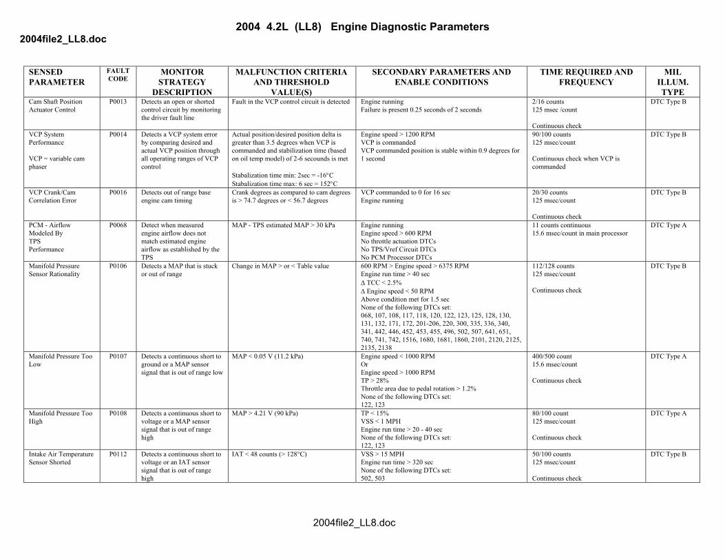
2004 4.2L (LL8) Engine Diagnostic Parameters 2004file2_LL8.doc
SENSED PARAMETER
FAULT CODE
MONITOR STRATEGY
MALFUNCTION CRITERIA AND THRESHOLD
SECONDARY PARAMETERS AND ENABLE CONDITIONS
TIME REQUIRED AND FREQUENCY
MIL ILLUM.
DESCRIPTION VALUE(S) TYPE Intake Air Temperature Sensor Open
P0113 Detects a continuous short to ground or an open in the IAT sensor signal
IAT > 253 counts (< -57°C) VSS < 15 MPH Engine run time > 320 sec ECT > -40°C None of the following DTCs set: 117, 118, 125, 502, 503
50/100 counts 125 msec/count Continuous check
DTC Type B
Coolant Temperature Sensor Shorted
P0117 Detects a continuous short to voltage or an ECT sensor signal that is out of range high
ECT < 4 counts (> 138°C) (High R) Or ECT < 36 counts (> 142°C) (Low R)
Engine run time > 128 sec 50/100 counts 125 msec/count Continuous check
DTC Type B
Coolant Temperature Sensor Open
P0118 Detects a continuous short to ground or an open in the ECT sensor signal
ECT > 251 counts (< -50°C) (High R) Or ECT > 252 counts (< -71°C) (Low R)
Engine run time > 60 sec 50/100 counts 125 msec/count Continuous check
DTC Type B
TPS 1 Circuit P0120 Detect a continuous or intermittent short or open in the TPS1 circuit
0.275 V < TPS1 < 4.67 V Ignition in unlock/accessory, run, or crank System voltage > 5.23 V No PCM processor DTCs No Vref DTC – P0641 None of the following DTCs set: 0122, 0123
13/28 counts or 8 counts continuous, 15.6 msec/count in main processor 85/202 counts or 62 counts continuous, 2 msec/count in motor processor
DTC Type A
Throttle Position Sensor Low
P0122 Detects if ETC TPS1 is out of range low
TPS1 < 0.275 V Ignition in unlock/accessory, run, or crank System voltage > 5.23 V No PCM processor DTC No Vref DTC – P0641
13/28 counts or 8 counts continuous, 15.6 msec/count in main processor 85/202 counts or 62 counts continuous, 2 msec/count in motor processor
DTC Type A
Throttle Position Sensor High
P0123 Detects if ETC TPS1 is out of range high
TPS1 > 4.67 V Ignition in unlock/accessory, run, or crank System voltage > 5.23 V No PCM processor DTC No Vref DTC – P0641
13/28 counts or 8 counts continuous, 15.6 msec/count in main processor 85/202 counts or 62 counts continuous, 2 msec/count in the motor processor
DTC Type A
Closed Loop Engine Coolant Temperature Rationality
P0125 Detects if engine coolant temperature rises too slowly due to an ECT or cooling system fault
Coolant temperature < 40°C when total airflow ≥ a calculation (based on start-up coolant temperature, minimum IAT, engine run time) Cumulative airflow is accumulated when airflow > 10 grams/sec
30 sec < engine runtime < 30 min. Air Flow > 15 g/sec Min Average flow > 15 g/sec Min distance traveled > .5 miles Min MPH to update distance > 25 mph IAT > -7°C Start up ECT < 35°C None of the following DTCs set: 105, 107, 108, 112, 113, 116, 117, 118, 122, 123 ,130, 131, 132, 133, 171, 172, 201, 202, 203, 204, 205, 206, 300, 335, 351, -356, 420, 440, 442, 446, 452, 453, 502, 503, 601, 602, 604, 606, 1120, 1220, 1221, 1275, 1271, 1280, 1441, 1481, 1482, 1484, 1512, 1514, 1515, 1516, 1635, 1639, 1680, 1681,
60 counts 1 sec/count Once per ignition cycle
DTC Type B
2004file2_LL8.doc

2004 4.2L (LL8) Engine Diagnostic Parameters 2004file2_LL8.doc
SENSED PARAMETER
FAULT CODE
MONITOR STRATEGY
MALFUNCTION CRITERIA AND THRESHOLD
SECONDARY PARAMETERS AND ENABLE CONDITIONS
TIME REQUIRED AND FREQUENCY
MIL ILLUM.
DESCRIPTION VALUE(S) TYPE Thermostat Engine Coolant Temperature Rationality
P0128 Detects if engine coolant temperature rises too slowly due to an ECT or cooling system fault
Coolant temperature < 75°C when total airflow ≥ a calculation (based on start-up coolant temperature, minimum IAT, engine run time) Cumulative airflow is accumulated when airflow > 10 grams/sec
30 sec < engine runtime < 30 min. Air Flow > 15 g/sec Min Average flow > 15 g/sec Min distance traveled > 1.5 miles Min MPH to update distance > 25 mph IAT > -7°C Start up ECT < 75°C None of the following DTCs set: 105, 107, 108, 112, 113, 116, 117, 118, 122, 123 ,130, 131, 132, 133, 171, 172, 201, 202, 203, 204, 205, 206, 300-306, 335, 351, -356, 420, 440, 442, 446, 452, 453, 502, 503, 601, 602, 604, 606, 1120, 1220, 1221, 1275, 1271, 1280, 1441, 1481, 1482, 1484, 1512, 1514, 1515, 1516, 1635, 1639, 1680, 1681,
60 counts 1 sec/count Once per ignition cycle
DTC Type B
O2S 1 Closed Loop Rationality
P0130 Detects an abnormal open loop condition due to O2 sensor signal in “not ready” range.
O2 voltage stuck between 300 and 600 mV (Sensor becomes “not ready” after 6 seconds)
ECT > 70.3°C Engine run time > 200 secs 1200 RPM < Engine speed < 3400 RPM 15% < TP < 50% Partial pedal enabled Above conditions met for 2 sec None of the following DTCs set: 68,106, 107, 108, 112, 113, 117, 118, 120, 122, 123, 125, 128, 171, 172, 201-206, 220, 300-306, 315, 336, 442, 446, 452, 453, 455, 483, 496, 506, 507, 601, 602, 604, 606, 641, 651, 1516, 1621, 1680, 1681, 2101, 2120, 2125, 2135, 2138, 2176
90/100 counts 8 counts/sec Continuous check
DTC Type B
O2S 1 Lean P0131 Detects an O2S 1 signal that is shorted to ground.
O2S 1 < 52 mV ECT > 69.5°C Fuel level > 9.8% System voltage > 11 V Engine run time > 10 sec No intrusive CATMON test active Closed Loop/Stoich 15% < TP < 50.2% MAP > 25 KPa Partial pedal enabled Above conditions met for 3.8 seconds None of the following DTCs set: 68, 106, 107, 108, 112, 113, 117, 118, 120, 122, 123, 125, 128, 201-206, 220, 300-306, 315, 336, 442, 446, 452, 453, 455, 483, 496, 506, 507, 601, 602, 604, 606, 641, 651, 1516, 1621, 1680, 1681, 2101, 2120, 2125, 2135, 2138, 2176
999/1000 counts 8 counts/sec Continuous check
DTC Type B
2004file2_LL8.doc
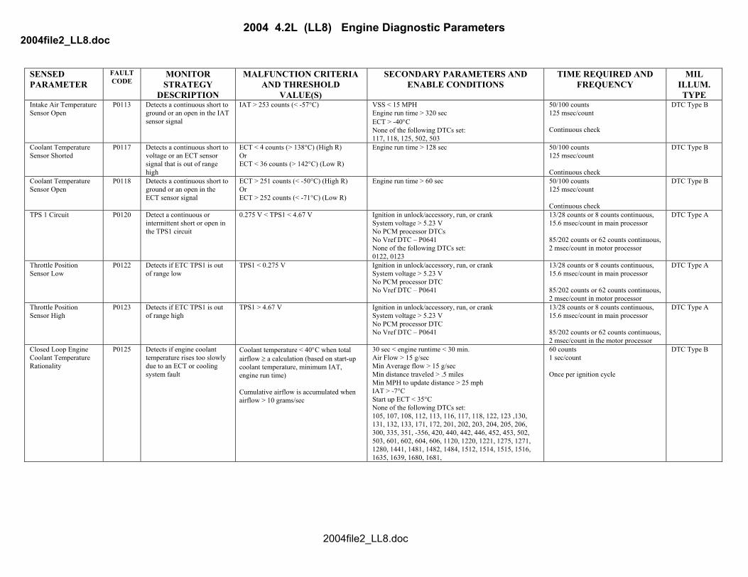
2004 4.2L (LL8) Engine Diagnostic Parameters 2004file2_LL8.doc
SENSED PARAMETER
FAULT CODE
MONITOR STRATEGY
MALFUNCTION CRITERIA AND THRESHOLD
SECONDARY PARAMETERS AND ENABLE CONDITIONS
TIME REQUIRED AND FREQUENCY
MIL ILLUM.
DESCRIPTION VALUE(S) TYPE O2S 1 Rich P0132 Detects an O2S 1 signal that
is shorted to voltage. O2S1 > 946 mV while in closed loop or O2S1 > 998 mV while in open loop. (If O2S 1 > 1024 mV for 1 second straight, system goes open loop)
ECT > 69.5°C Fuel level > 9.8% System voltage > 11 V Engine run time > 10 sec No intrusive CATMON test active Closed Loop/Stoich 15% < TP < 50.2% MAP > 25 KPa Partial pedal enabled Above conditions met for 3.8 seconds None of the following DTCs set: 68, 106, 107, 108, 112, 113, 117, 118, 120, 122, 123, 125, 128, 201-206, 220, 300-306, 315, 336, 442, 446, 452, 453, 455, 483, 496, 506, 507, 601, 602, 604, 606, 641, 651, 1516, 1621, 1680, 1681, 2101, 2120, 2125, 2135, 2138, 2176
399/400 counts above 946 mV while in closed loop or 350 /4 00 counts above 998 mV while in open loop 8 counts/sec Continuous check
DTC Type B
O2S 1 Slow Response P0133 Determines if the O2S 1 is functioning properly by checking its response time
Average O2S1 response times: R/L > 75 msec L/R > 75 msec
ECT > 69.5°C Fuel level > 9.8% System voltage > 11 V Engine run time > 170 sec No intrusive CATMON test active 5% < TP < 60% Delta TP < 18.75% per sec 1000 RPM < Engine speed < 3500 RPM Airflow > 25 grams/second Closed Loop/Stoich Time in enable > 1.7 sec None of the following DTCs set: 68, 106, 107, 108, 112, 113, 117, 118, 120, 122, 123, 125, 128, 201-206, 220, 300-306, 315, 336, 442, 446, 452, 453, 455, 483, 496, 506, 507, 601, 602, 604, 606, 641, 651, 1516, 1621, 1680, 1681, 2101, 2120, 2125, 2135, 2138, 2176
60 sec Once per trip
DTC Type B
O2S 1 Open P0134 Detects an O2S 1 signal open circuit.
400 mV < O2S1 < 500 mV ECT > 69.5°C Fuel level > 9.8% System voltage > 11 V Engine run time > 30 sec No intrusive CATMON test active 15% < TP < 50% MAP > 25 kPa Partial pedal enabled Sensor predicted warm (O2 front sensor warm flag set) None of the following DTCs set: 68, 106, 107, 108, 112, 113, 117, 118, 120, 122, 123, 125, 128, 201-206, 220, 300-306, 315, 336, 442, 446, 452, 453, 455, 483, 496, 506, 507, 601, 602, 604, 606, 641, 651, 1516, 1621, 1680, 1681, 2101, 2120, 2125, 2135, 2138, 2176
999/1000 counts 8 counts/sec Continuous check
DTC Type B
2004file2_LL8.doc
2004 4.2L (LL8) Engine Diagnostic Parameters 2004file2_LL8.doc
SENSED PARAMETER
FAULT CODE
MONITOR STRATEGY
MALFUNCTION CRITERIA AND THRESHOLD
SECONDARY PARAMETERS AND ENABLE CONDITIONS
TIME REQUIRED AND FREQUENCY
MIL ILLUM.
DESCRIPTION VALUE(S) TYPE O2S 1 Heater Circuit Malfunction
P0135 Detects O2 heater current out of acceptable range.
0.8 amps < O2S1 current < 3 amps ECT > 69.5°C Fuel level > 9.8% Engine run time > 60 sec No intrusive CATMON test active 11 V < system voltage < 18 V Predicted oxygen sensor temperature > 845°C None of the following DTCs set: 68, 106, 107, 108, 112, 113, 117, 118, 120, 122, 123, 125, 128, 201-206, 220, 300-306, 315, 336, 442, 446, 452, 453, 455, 483, 496, 506, 507, 601, 602, 604, 606, 641, 651, 1516, 1621, 1680, 1681, 2101, 2120, 2125, 2135, 2138, 2176
198/200 counts 1 count/sec Continuous check
DTC Type B
O2S 2 Post Oxygen Sensor Diagnostic (POSD)
P0136 Detects Post O2 sensor that has insufficient range to detect degraded catalyst or to provide closed loop fuel correction
300 mV < O2S2 < 750 mV Pre-catalyst sensor voltage must have been above 600 mV for post sensor to fail stage 2 rich test and below 300 mV for post sensor to fail stage 2 lean test
Stage 1 (Passive portion): Engine run time > 2 sec Stage 2 (Intrusive portion): Stage 1 enabled time > 720 sec Stage 1 not passed System voltage > 11 V 15 grams/second <MAF < 100 grams/second -20% < Short term FT < +20% No short term FT resets during intrusive test 1000 RPM < Engine speed < 5000 RPM 20 MPH < Vehicle speed < 80 MPH Above conditions must be met for 1 sec The following DTCs not set: 68, 106, 107, 108, 112, 113, 117, 118, 120, 122, 123, 125, 128, 130, 131, 132, 137, 138, 140, 141, 171, 172, 201-206, 220, 300-306, 315, 366, 442, 446, 452, 453, 455, 496, 506, 507, 601, 602, 604, 606, 641, 651, 1516, 1621, 1680, 1681, 2101, 2120, 2125, 2135, 2138, 2176
Stage 1 (Passive portion): Once per trip Stage 2 (Intrusive portion): Lean test - 10 sec Rich test - 10 sec Once per trip
DTC Type B
O2S 2 Lean P0137 Detects an O2S 2 signal that is shorted to ground.
O2S2 < 43.4 mV ECT > 69.5°C Fuel level > 9.8% System voltage > 11 V Engine run time > 10 sec No intrusive CATMON test active Closed Loop/Stoich 15% < TP <50.2% MAP > 25 KPa Above conditions met for 3.8 seconds None of the following DTCs set: 68, 106, 107, 108, 112, 113, 117, 118, 120, 122, 123, 125, 128, 201-206, 220, 300-306, 315, 336, 442, 446, 452, 453, 455, 483, 496, 506, 507, 601, 602, 604, 606, 641, 651, 1516, 1621, 1680, 1681, 2101, 2120, 2125, 2135, 2138, 2176
1199/1200 counts 8 counts/sec Continuous check
DTC Type B
2004file2_LL8.doc
2004 4.2L (LL8) Engine Diagnostic Parameters 2004file2_LL8.doc
SENSED PARAMETER
FAULT CODE
MONITOR STRATEGY
MALFUNCTION CRITERIA AND THRESHOLD
SECONDARY PARAMETERS AND ENABLE CONDITIONS
TIME REQUIRED AND FREQUENCY
MIL ILLUM.
DESCRIPTION VALUE(S) TYPE O2S 2 Rich P0138 Detects an O2S 2 signal that
is shorted to voltage. O2S2 > 1042 mV ECT > 69.5°C
Fuel level > 9.8% System voltage > 11 V Engine run time > 10 sec No intrusive CATMON test active Closed Loop/Stoich 15% < TP < 50.2% MAP > 25 KPa Above conditions met for 3.8 seconds None of the following DTCs set: 68, 106, 107, 108, 112, 113, 117, 118, 120, 122, 123, 125, 128, 201-206, 220, 300-306, 315, 336, 442, 446, 452, 453, 455, 483, 496, 506, 507, 601, 602, 604, 606, 641, 651, 1516, 1621, 1680, 1681, 2101, 2120, 2125, 2135, 2138, 2176
399/400 counts 8 counts/sec Continuous check
DTC Type B
O2S 2 Open P0140 Detects an O2S 2 signal open circuit.
425 mV < O2S 2 < 473 mV ECT > 69.5°C Fuel level > 9.8% System voltage > 11 V Engine run time > 10 sec No intrusive CATMON test active MAP > 25 KPa 15% < TP < 50% Partial pedal enabled Sensor predicted warm (O2 front sensor warm flag set) None of the following DTCs set: 68, 106, 107, 108, 112, 113, 117, 118, 120, 122, 123, 125, 128, 201-206, 220, 300-306, 315, 336, 442, 446, 452, 453, 455, 483, 496, 506, 507, 601, 602, 604, 606, 641, 651, 1516, 1621, 1680, 1681, 2101, 2120, 2125, 2135, 2138, 2176
999/1000 counts 8 counts/sec Continuous check
DTC Type B
O2S 2 Heater Circuit Malfunction
P0141 Detects O2 heater current out of acceptable range.
0.221 A < O2S2 current < 1.6 A ECT > 69.5°C Fuel level > 9.8% No intrusive CATMON test active Engine run time > 60 sec 11 < System voltage < 18 volts Predicted oxygen sensor temperature > 805°C None of the following DTCs set: 68, 106, 107, 108, 112, 113, 117, 118, 120, 122, 123, 125, 128, 201-206, 220, 300-306, 315, 336, 442, 446, 452, 453, 455, 483, 496, 506, 507, 601, 602, 604, 606, 641, 651, 1516, 1621, 1680, 1681, 2101, 2120, 2125, 2135, 2138, 2176
198/200 counts 1 count/sec Continuous check
DTC Type B
2004file2_LL8.doc
2004 4.2L (LL8) Engine Diagnostic Parameters 2004file2_LL8.doc
SENSED PARAMETER
FAULT CODE
MONITOR STRATEGY
MALFUNCTION CRITERIA AND THRESHOLD
SECONDARY PARAMETERS AND ENABLE CONDITIONS
TIME REQUIRED AND FREQUENCY
MIL ILLUM.
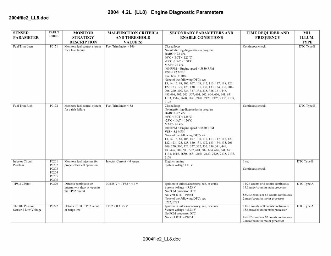
DESCRIPTION VALUE(S) TYPE Fuel Trim Lean P0171 Monitors fuel control system
for a lean failure Fuel Trim Index > 146 Closed loop
No interferring diagnostics in progress BARO > 72 kPa 60°C < ECT < 125°C -25°C < IAT < 150°C MAP > 26 kPa 400 RPM < Engine speed < 5850 RPM VSS < 82 MPH Fuel level > 10% None of the following DTCs set: 13, 14, 16, 68, 106, 107, 108, 112, 113, 117, 118, 120, 122, 123, 125, 128, 130, 131, 132, 133, 134, 135, 201-206, 220, 300, 326, 327, 332, 335, 336, 341, 446, 483,496, 502, 503, 507, 601, 602, 604, 606, 641, 651, 1133, 1516, 1680, 1681, 2101, 2120, 2125, 2135, 2138, 2176
Continuous check DTC Type B
Fuel Trim Rich P0172 Monitors fuel control system for a rich failure
Fuel Trim Index < 82 Closed loop No interferring diagnostics in progress BARO > 72 kPa 60°C < ECT < 125°C -25°C < IAT < 150°C MAP > 26 kPa 400 RPM < Engine speed < 5850 RPM VSS < 82 MPH None of the following DTCs set: 13, 14, 16, 68, 106, 107, 108, 112, 113, 117, 118, 120, 122, 123, 125, 128, 130, 131, 132, 133, 134, 135, 201-206, 220, 300, 326, 327, 332, 335, 336, 341, 446, 483,496, 502, 503, 507, 601, 602, 604, 606, 641, 651, 1133, 1516, 1680, 1681, 2101, 2120, 2125, 2135, 2138, 2176
Continuous check DTC Type B
Injector Circuit Problem
P0201 P0202 P0203 P0204 P0205 P0206
Monitors fuel injectors for proper electrical operation
Injector Current < 4 Amps Engine running System voltage >11 V
1 sec Continuous check
DTC Type B
TPS 2 Circuit P0220 Detect a continuous or intermittent short or open in the TPS2 circuit.
0.3125 V < TPS2 < 4.7 V Ignition in unlock/accessory, run, or crank System voltage > 5.23 V No PCM processor DTC No Vref DTC – P0651 None of the following DTCs set: 0222, 0223
11/26 counts or 8 counts continuous, 15.6 msec/count in main processor 85/202 counts or 62 counts continuous, 2 msec/count in motor processor
DTC Type A
Throttle Position Sensor 2 Low Voltage
P0222 Detects if ETC TPS2 is out of range low
TPS2 < 0.3125 V Ignition in unlock/accessory, run, or crank System voltage > 5.23 V No PCM processor DTC No Vref DTC – P0651
11/26 counts or 8 counts continuous, 15.6 msec/count in main processor 85/202 counts or 62 counts continuous, 2 msec/count in motor processor
DTC Type A
2004file2_LL8.doc

2004 4.2L (LL8) Engine Diagnostic Parameters 2004file2_LL8.doc
SENSED PARAMETER
FAULT CODE
MONITOR STRATEGY
MALFUNCTION CRITERIA AND THRESHOLD
SECONDARY PARAMETERS AND ENABLE CONDITIONS
TIME REQUIRED AND FREQUENCY
MIL ILLUM.
DESCRIPTION VALUE(S) TYPE Throttle Position Sensor 2 High Voltage
P0223 Detects if ETC TPS2 is out of range high
TPS2 > 4.7 V Ignition in unlock/accessory, run, or crank System voltage > 5.23 V No PCM processor DTC No Vref DTC – P0651
11/26 counts or 8 counts continuous, 15.6 msec/count in main processor 85/202 counts or 62 counts continuous, 2 msec/count in motor processor
DTC Type A
Random Misfire Cylinder 1 Misfire Cylinder 2 Misfire Cylinder 3 Misfire Cylinder 4 Misfire Cylinder 5 Misfire Cylinder 6 Misfire
P0300
P0301 P0302 P0303 P0304 P0305 P0306
These DTCs will determine if a random misfire or a cylinder specific misfire is occurring by monitoring crankshaft velocity.
Deceleration index Vs
Engine Speed Vs
Load and Camshaft Position Emission Failure Threshold = 1.0% Catalyst Damage Threshold = 5.0%-14.6%, depending on engine speed and engine load.
Engine run time > 1 engine cycle 438 RPM < Engine speed < 6250 RPM -7°C < ECT < 125°C. If start up ECT < -7°C, then disable until ECT > 21°C. Fuel level > 4% System voltage > 9 V Fuel cutoff not active Power management is not active Brake torque management not active No ABS rough road No ABS or TCS active Positive or zero torque Camshaft sensor is in sync with crank sensor + Throttle position ∆ < 7% - Throttle position ∆ < 5% Misfire diag is not requesting to disable TCC when transmission is in hot mode. None of the following DTCs set: 13, 14, 16, 68, 106, 107, 108, 112, 113, 117, 118, 120, 122, 123, 125, 128, 130, 131, 132, 133, 134, 171, 172, 220, 315, 326, 327, 332, 335, 336, 483, 502, 503, 506, 507, 601, 602, 604, 606, 641, 651, 740, 742, 1133, 1516, 1621, 1680, 1681, 2101, 2120, 2125, 2135, 2138, 2176 The following are not currently utilized (N/A): Power Take Off is disabled –N/A EGR Intrusive test not active – N/A AIR Intrusive test not active – N/A Automatic transmission is not shifting – N/A
Emission Exceedence = (5) failed 200 revolution blocks of 16. Failure reported with (1) Exceedence in 1st (16) 200 revolution block, or (4) Exceedences thereafter. 1st Catalyst Exceedence = Number of 200 revolution blocks as data supports for catalyst damage. 2nd and 3rd Catalyst Exceedence = (1) 200 revolution block with catalyst damage. Failure reported with (3) Exceedences in FTP, or (1) Exceedence outside FTP. Continuous check.
DTC Type B Emission DTC Type A Catalyst damaging
Crankshaft Position System Variation Not Learned (CASE)
P0315 Determines if the Crankshaft Position System Variation has not been learned.
Sum of compensation factors between 98172 and 98435.
Manufacturers Enable Counter must be zero. None of the following DTCs: 335, 336, 340, 341.
0.5 sec. Once per ignition cycle
DTC Type A
ESC System Diagnostic P0326 Detects a ESC System fault Inst Volt< 0.01V or Inst Volt > 4.99V 2000 RPM < Engine speed < 6400 RPM ECT > 70°C MAP > 34.8 kPa Engine run time > 20 sec 0 kPa < Vacuum < 40 kPa None of the following DTCs set: 117, 118, 122, 123, 327
60/80 counts Continuous check
DTC Type B
2004file2_LL8.doc
2004 4.2L (LL8) Engine Diagnostic Parameters 2004file2_LL8.doc
SENSED PARAMETER
FAULT CODE
MONITOR STRATEGY
MALFUNCTION CRITERIA AND THRESHOLD
SECONDARY PARAMETERS AND ENABLE CONDITIONS
TIME REQUIRED AND FREQUENCY
MIL ILLUM.
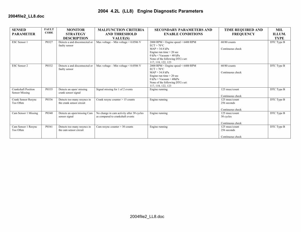
DESCRIPTION VALUE(S) TYPE ESC Sensor 1 P0327 Detects a and disconnected or
faulty sensor Max voltage – Min voltage < 0.0586 V 2000 RPM < Engine speed < 6400 RPM
ECT > 70°C MAP > 34.8 kPa Engine run time > 20 sec 0 kPa < Vacuum < 40 kPa None of the following DTCs set: 117, 118, 122, 123
60/80 counts Continuous check
DTC Type B
ESC Sensor 2 P0332 Detects a and disconnected or faulty sensor
Max voltage – Min voltage < 0.0586 V 2000 RPM < Engine speed < 6400 RPM ECT > 70°C MAP > 34.8 kPa Engine run time > 20 sec 0 kPa < Vacuum < 40kPa None of the following DTCs set: 117, 118, 122, 123
60/80 counts Continuous check
DTC Type B
Crankshaft Position Sensor Missing
P0335 Detects an open/ missing crank sensor signal
Signal missing for 1 of 2 events Engine running 125 msec/count Continuous check
DTC Type B
Crank Sensor Resync Too Often
P0336 Detects too many resyncs in the crank sensor circuit
Crank resync counter > 15 counts Engine running 125 msec/count 256 seconds Continuous check
DTC Type B
Cam Sensor 1 Missing P0340 Detects an open/missing Cam sensor signal
No change in cam activity after 30 cycles as compared to crankshaft events
Engine running 125 msec/count 30 cycles Continuous check
DTC Type B
Cam Sensor 1 Resync Too Often
P0341 Detects too many resyncs in the cam sensor circuit
Cam resync counter > 30 counts Engine running 125 msec/count 256 seconds Continuous check
DTC Type B
2004file2_LL8.doc

2004 4.2L (LL8) Engine Diagnostic Parameters 2004file2_LL8.doc
SENSED PARAMETER
FAULT CODE
MONITOR STRATEGY
MALFUNCTION CRITERIA AND THRESHOLD
SECONDARY PARAMETERS AND ENABLE CONDITIONS
TIME REQUIRED AND FREQUENCY
MIL ILLUM.
DESCRIPTION VALUE(S) TYPE Secondary AIR Injection System
P0410 Detects secondary air system failures
Passive Part 1: Cold (Startup ETC < 9.5°C): Lean ratio < 0.4 or Rich ratio > 0.4 Hot (Startup ETC > 9.5°C): Lean ratio < 0.5 or Rich ratio > 0.4 Passive Part 2: Rich samples (> 650 mV) < 10 in 10 sec Active: Lean time < 1 second during 3.125 second active test compared to O2 voltage threshold of 52 mV during 2 attemps
AIR system commanded on >20 sec -0.25°C < IAT < 150.5°C 2.75°C < ECT < 114.5°C System voltage > 11 V Engine load < 30 kPa TP ∆ < 10% Passive specific: Engine run time > 5 sec A/F > 8 Start up ECT < 50°C Active specific: Engine speed > 1000 RPM Engine run time > 200 sec Accumulated flow > 200 counts Long term FT memory cell of 16, 17 Fuel injector pulse width > 0.5 msec 110 < Short term FT <138 Stabilization time > 0.5 seconds None of the following DTCs set: 106, 107, 108, 112, 113, 117, 118, 120, 122, 123, 125, 128, 130, 131, 132, 133, 134, 135, 171, 172, 201-206, 300, 335, 336, 340, 341, 442, 446, 496,506, 507, 601, 602, 604, 606, 1133, 1621
Passive: Any key cycle when AIR system is commanded on (30 sec test time) Active: When Passive test fails or is inconclusive (3.125 sec test time, max of 2 attempts)
DTC Type B
2004file2_LL8.doc
2004 4.2L (LL8) Engine Diagnostic Parameters 2004file2_LL8.doc
SENSED PARAMETER
FAULT CODE
MONITOR STRATEGY
MALFUNCTION CRITERIA AND THRESHOLD
SECONDARY PARAMETERS AND ENABLE CONDITIONS
TIME REQUIRED AND FREQUENCY
MIL ILLUM.
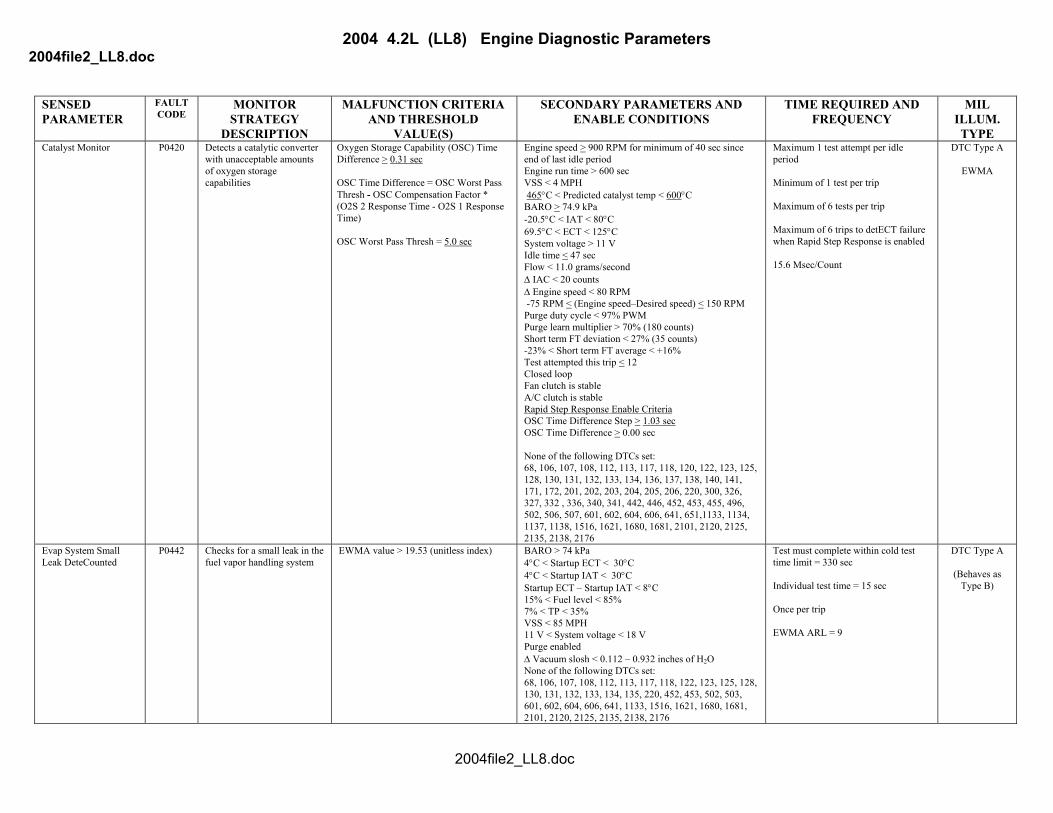
DESCRIPTION VALUE(S) TYPE Catalyst Monitor P0420 Detects a catalytic converter
with unacceptable amounts of oxygen storage capabilities
Oxygen Storage Capability (OSC) Time Difference > 0.31 sec OSC Time Difference = OSC Worst Pass Thresh - OSC Compensation Factor * (O2S 2 Response Time - O2S 1 Response Time) OSC Worst Pass Thresh = 5.0 sec
Engine speed > 900 RPM for minimum of 40 sec since end of last idle period Engine run time > 600 sec VSS < 4 MPH 465°C < Predicted catalyst temp < 600°C BARO > 74.9 kPa -20.5°C < IAT < 80°C 69.5°C < ECT < 125°C System voltage > 11 V Idle time < 47 sec Flow < 11.0 grams/second ∆ IAC < 20 counts ∆ Engine speed < 80 RPM -75 RPM < (Engine speed–Desired speed) < 150 RPM Purge duty cycle < 97% PWM Purge learn multiplier > 70% (180 counts) Short term FT deviation < 27% (35 counts) -23% < Short term FT average < +16% Test attempted this trip < 12 Closed loop Fan clutch is stable A/C clutch is stable Rapid Step Response Enable Criteria OSC Time Difference Step > 1.03 sec OSC Time Difference > 0.00 sec None of the following DTCs set: 68, 106, 107, 108, 112, 113, 117, 118, 120, 122, 123, 125, 128, 130, 131, 132, 133, 134, 136, 137, 138, 140, 141, 171, 172, 201, 202, 203, 204, 205, 206, 220, 300, 326, 327, 332 , 336, 340, 341, 442, 446, 452, 453, 455, 496, 502, 506, 507, 601, 602, 604, 606, 641, 651,1133, 1134, 1137, 1138, 1516, 1621, 1680, 1681, 2101, 2120, 2125, 2135, 2138, 2176
Maximum 1 test attempt per idle period Minimum of 1 test per trip Maximum of 6 tests per trip Maximum of 6 trips to detECT failure when Rapid Step Response is enabled 15.6 Msec/Count
DTC Type A
EWMA
Evap System Small Leak DeteCounted
P0442 Checks for a small leak in the fuel vapor handling system
EWMA value > 19.53 (unitless index) BARO > 74 kPa 4°C < Startup ECT < 30°C 4°C < Startup IAT < 30°C Startup ECT – Startup IAT < 8°C 15% < Fuel level < 85% 7% < TP < 35% VSS < 85 MPH 11 V < System voltage < 18 V Purge enabled ∆ Vacuum slosh < 0.112 – 0.932 inches of H2O None of the following DTCs set: 68, 106, 107, 108, 112, 113, 117, 118, 122, 123, 125, 128, 130, 131, 132, 133, 134, 135, 220, 452, 453, 502, 503, 601, 602, 604, 606, 641, 1133, 1516, 1621, 1680, 1681, 2101, 2120, 2125, 2135, 2138, 2176
Test must complete within cold test time limit = 330 sec Individual test time = 15 sec Once per trip EWMA ARL = 9
DTC Type A
(Behaves as Type B)
2004file2_LL8.doc
2004 4.2L (LL8) Engine Diagnostic Parameters 2004file2_LL8.doc
SENSED PARAMETER
FAULT CODE
MONITOR STRATEGY
MALFUNCTION CRITERIA AND THRESHOLD
SECONDARY PARAMETERS AND ENABLE CONDITIONS
TIME REQUIRED AND FREQUENCY
MIL ILLUM.
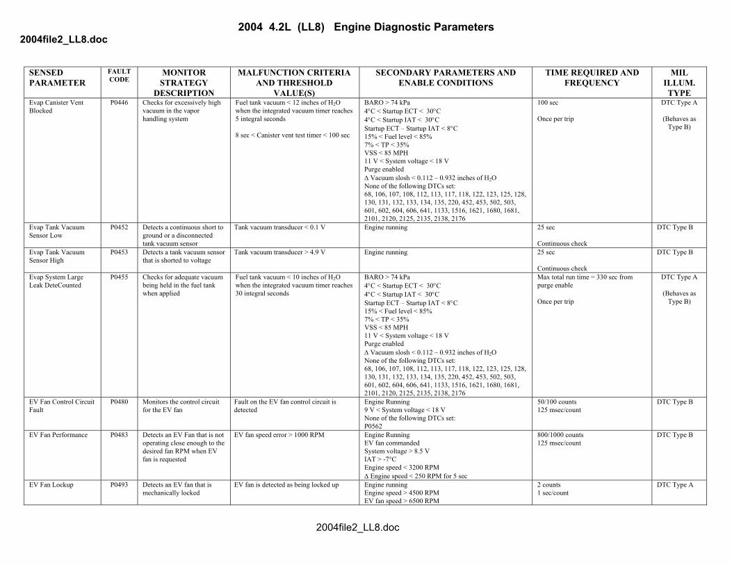
DESCRIPTION VALUE(S) TYPE Evap Canister Vent Blocked
P0446 Checks for excessively high vacuum in the vapor handling system
Fuel tank vacuum < 12 inches of H2O when the integrated vacuum timer reaches 5 integral seconds 8 sec < Canister vent test timer < 100 sec
BARO > 74 kPa 4°C < Startup ECT < 30°C 4°C < Startup IAT < 30°C Startup ECT – Startup IAT < 8°C 15% < Fuel level < 85% 7% < TP < 35% VSS < 85 MPH 11 V < System voltage < 18 V Purge enabled ∆ Vacuum slosh < 0.112 – 0.932 inches of H2O None of the following DTCs set: 68, 106, 107, 108, 112, 113, 117, 118, 122, 123, 125, 128, 130, 131, 132, 133, 134, 135, 220, 452, 453, 502, 503, 601, 602, 604, 606, 641, 1133, 1516, 1621, 1680, 1681, 2101, 2120, 2125, 2135, 2138, 2176
100 sec Once per trip
DTC Type A
(Behaves as Type B)
Evap Tank Vacuum Sensor Low
P0452 Detects a continuous short to ground or a disconnected tank vacuum sensor
Tank vacuum transducer < 0.1 V Engine running 25 sec Continuous check
DTC Type B
Evap Tank Vacuum Sensor High
P0453 Detects a tank vacuum sensor that is shorted to voltage
Tank vacuum transducer > 4.9 V Engine running 25 sec Continuous check
DTC Type B
Evap System Large Leak DeteCounted
P0455 Checks for adequate vacuum being held in the fuel tank when applied
Fuel tank vacuum < 10 inches of H2O when the integrated vacuum timer reaches 30 integral seconds
BARO > 74 kPa 4°C < Startup ECT < 30°C 4°C < Startup IAT < 30°C Startup ECT – Startup IAT < 8°C 15% < Fuel level < 85% 7% < TP < 35% VSS < 85 MPH 11 V < System voltage < 18 V Purge enabled ∆ Vacuum slosh < 0.112 – 0.932 inches of H2O None of the following DTCs set: 68, 106, 107, 108, 112, 113, 117, 118, 122, 123, 125, 128, 130, 131, 132, 133, 134, 135, 220, 452, 453, 502, 503, 601, 602, 604, 606, 641, 1133, 1516, 1621, 1680, 1681, 2101, 2120, 2125, 2135, 2138, 2176
Max total run time = 330 sec from purge enable Once per trip
DTC Type A
(Behaves as Type B)
EV Fan Control Circuit Fault
P0480 Monitors the control circuit for the EV fan
Fault on the EV fan control circuit is detected
Engine Running 9 V < System voltage < 18 V None of the following DTCs set: P0562
50/100 counts 125 msec/count
DTC Type B
EV Fan Performance P0483 Detects an EV Fan that is not operating close enough to the desired fan RPM when EV fan is requested
EV fan speed error > 1000 RPM Engine Running EV fan commanded System voltage > 8.5 V IAT > -7°C Engine speed < 3200 RPM ∆ Engine speed < 250 RPM for 5 sec
800/1000 counts 125 msec/count
DTC Type B
EV Fan Lockup P0493 Detects an EV fan that is mechanically locked
EV fan is detected as being locked up Engine running Engine speed > 4500 RPM EV fan speed > 6500 RPM
2 counts 1 sec/count
DTC Type A
2004file2_LL8.doc

2004 4.2L (LL8) Engine Diagnostic Parameters 2004file2_LL8.doc
SENSED PARAMETER
FAULT CODE
MONITOR STRATEGY
MALFUNCTION CRITERIA AND THRESHOLD
SECONDARY PARAMETERS AND ENABLE CONDITIONS
TIME REQUIRED AND FREQUENCY
MIL ILLUM.
DESCRIPTION VALUE(S) TYPE EV Fan Speed Too High
P0495 Detects an EV fan that is turning too fast when EV Fan is not requested
EV fan speed > 1600 RPM Engine Running EV fan not commanded System voltage > 8.5 V IAT > -7°C Engine speed > 1800 RPM for 120 seconds
650/2500 counts 125 msec/count
DTC Type B
Evap Purge Valve Leaking
P0496 Checks for a stuck open purge solenoid
Fuel tank vacuum > 7 inches of H2O when the integrated vacuum timer reaches 8 integral seconds 10 sec < Purge solenoid leak timer < 120 sec
BARO > 74 kPa 4°C < Startup ECT < 30°C 4°C < Startup IAT < 30°C Startup ECT – Startup IAT < 8°C 15% < Fuel level < 85% 7% < TP < 35% VSS < 85 MPH 11 V < System voltage < 18 V 1st failure: Purge enabled 2nd failure: Purge does not need to be enabled ∆ Vacuum slosh < 0.112 – 0.932 inches of H2O None of the following DTCs set: 68, 106, 107, 108, 112, 113, 117, 118, 122, 123, 125, 128, 130, 131, 132, 133, 134, 135, 220, 452, 453, 502, 503, 601, 602, 604, 606, 641, 1133, 1516, 1621, 1680, 1681, 2101, 2120, 2125, 2135, 2138, 2176
Max run time = 120 sec Once per trip
DTC Type A
(Behaves as Type B)
Idle Control System – RPM Lower than Expected
P0506 Detect an idle speed which is less than a delta from desired speed
Idle speed > 75 RPM below desired speed Engine run time > 2 sec BARO > 65 kPa ECT > -40°C Commanded IAC position > 400 Steps Idle stabilized for 5 sec System voltage > 9 V None of the following DTCs set: 68, 16, 107, 108, 112, 113, 117, 118, 120, 122, 123, 125, 130, 171, 172, 201-206, 220, 222, 223, 300, 336, 440, 442, 446, 452, 453, 502, 503, 606, 641, 651, 1516, 2101, 2176
18.75 sec Continuous check
DTC Type B
Idle Control System – RPM Higher than Expected
P0507 Detect an idle speed which is greater than a delta from desired speed
Idle speed > 150 RPM above desired speed Engine run time > 2 sec BARO > 65 kPa ECT > -40°C Commanded IAC position < 2 steps Idle stabilized for 5 sec System voltage > 9 V None of the following DTCs set: 68, 16, 107, 108, 112, 113, 117, 118, 120, 122, 123, 125, 130, 171, 172, 201-206, 220, 222, 223, 300, 336, 440, 442, 446, 452, 453, 502, 503, 606, 641, 651, 1516, 2101, 2176
15 sec Continuous check
DTC Type A
EV Fan Speed Input Circuit
P0526 Detects a continuous short or open in the EV fan speed Input circuit(s)
No EV fan speed input activity is detected Engine Running System voltage > 8.5 Volts
90/100 counts 125 msec/count
DTC Type B
PCM Has EEPROM Flash Error
P0601 Checks for an incorrECT checksum or Program ID failure
Checksum detection incorrect Ignition in unlock/accessory, run, or crank. System voltage > 5.23 V
3 counts continuous Continuous check
DTC Type A
2004file2_LL8.doc

2004 4.2L (LL8) Engine Diagnostic Parameters 2004file2_LL8.doc
SENSED PARAMETER
FAULT CODE
MONITOR STRATEGY
MALFUNCTION CRITERIA AND THRESHOLD
SECONDARY PARAMETERS AND ENABLE CONDITIONS
TIME REQUIRED AND FREQUENCY
MIL ILLUM.
DESCRIPTION VALUE(S) TYPE PCM EEPROM Not Programmed
P0602 Checks for a PCM that is not programmed
Unprogrammed EEPROM Ignition in unlock/accessory, run, or crank. System voltage > 5.23 V
Immediately Once per key cycle
DTC Type A
PCM – RAM Performance Test
P0604 Indicates that PCM is unable to correctly write and read data to and from RAM
Data read does not match Data written.
Ignition in unlock/accessory, run, or crank. System voltage > 5.23 V
One occurence Check is performed at powerup and every 60 seconds thereafter
DTC Type A
PCM - Processor Performance Check
P0606 Indicates that the PCM has detected an ETC internal processor integrity fault
Any of the following: 1. Motor processor desired throttle
limiting occuring, 2. ETC software is not executed in
proper order, 3. Software tasks loops exceed
schedule tasks loop, 4. Loss of serial peripheral interface
communication from the motor processor,
5. 1.45 msec < Average motor processor state of health toggle < 2.42 msec,
6. TPS or APPS minimum learned values fail compliment check,
7. TPS or APPS minimum learned values fail range check,
8. Main processor integrity check error occurs,
9. Motor processor integrity check error occurs,
10. Motor processor integrity check error of main processor occurs
Ignition in unlock/accessory, run, or crank. System voltage > 5.23 V
1. 99 counts continuous, 2 msec/count in the motor processor,
2. 1 count continuous, 15.6 msec/count in the main processor
3. Error > 3 counts per software tasks loops
4. 101/254 counts or 24 counts continuous or 37 counts continuous at initialization, 7.8 msec/count in main processor
5. 3 counts continuous, 62.5 msec/count
6. 13 counts continuous, 15.6 msec/count in main processor
7. 13 counts continuous;15.6 msec/count in main processor
8. 2 count continuous, check is performed at powerup and every 60 seconds thereafter
9. 2 count continuous.;15.6 msec/count in main processor
10. 1 count continuous, 15.6 msec/count in motor processor
DTC Type A
PCM – V5B1 Circuit P0641 Detect a continuous or intermittent short on the #1 5 volt sensor reference circuit
| Vref1 voltage - Vcc voltage | > 0.125 V Ignition in unlock/accessory, run, or crank System voltage > 5.23 V No PCM processor DTC
1. 16/32 counts or 11 counts continuous, 15.6 msec/count in main processor
2. 125/250 counts or 99 counts continuous, 2 msec/count in motor processor
DTC Type A
PCM – V5B2 Circuit P0651 Detect a continuous or intermittent short on the #2 5 volt sensor reference circuit
| Vref2 voltage - Vcc voltage | > 0.125 V Ignition in unlock/accessory, run, or crank System voltage > 5.23 V No PCM processor DTC
1. 16/32 counts or 11 counts continuous, 15.6 msec/count in main processor
2. 125/250 counts or 99 counts continuous, 2 msec/count in motor processor
DTC Type A
2004file2_LL8.doc
2004 4.2L (LL8) Engine Diagnostic Parameters 2004file2_LL8.doc
SENSED PARAMETER
FAULT CODE
MONITOR STRATEGY
MALFUNCTION CRITERIA AND THRESHOLD
SECONDARY PARAMETERS AND ENABLE CONDITIONS
TIME REQUIRED AND FREQUENCY
MIL ILLUM.
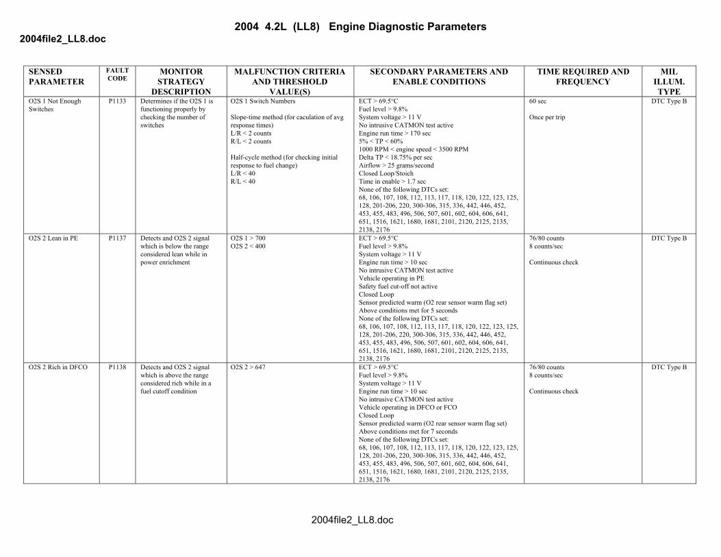
DESCRIPTION VALUE(S) TYPE O2S 1 Not Enough Switches
P1133 Determines if the O2S 1 is functioning properly by checking the number of switches
O2S 1 Switch Numbers Slope-time method (for caculation of avg response times) L/R < 2 counts R/L < 2 counts Half-cycle method (for checking initial response to fuel change) L/R < 40 R/L < 40
ECT > 69.5°C Fuel level > 9.8% System voltage > 11 V No intrusive CATMON test active Engine run time > 170 sec 5% < TP < 60% 1000 RPM < engine speed < 3500 RPM Delta TP < 18.75% per sec Airflow > 25 grams/second Closed Loop/Stoich Time in enable > 1.7 sec None of the following DTCs set: 68, 106, 107, 108, 112, 113, 117, 118, 120, 122, 123, 125, 128, 201-206, 220, 300-306, 315, 336, 442, 446, 452, 453, 455, 483, 496, 506, 507, 601, 602, 604, 606, 641, 651, 1516, 1621, 1680, 1681, 2101, 2120, 2125, 2135, 2138, 2176
60 sec Once per trip
DTC Type B
O2S 2 Lean in PE P1137 Detects and O2S 2 signal which is below the range considered lean while in power enrichment
O2S 1 > 700 O2S 2 < 400
ECT > 69.5°C Fuel level > 9.8% System voltage > 11 V Engine run time > 10 sec No intrusive CATMON test active Vehicle operating in PE Safety fuel cut-off not active Closed Loop Sensor predicted warm (O2 rear sensor warm flag set) Above conditions met for 5 seconds None of the following DTCs set: 68, 106, 107, 108, 112, 113, 117, 118, 120, 122, 123, 125, 128, 201-206, 220, 300-306, 315, 336, 442, 446, 452, 453, 455, 483, 496, 506, 507, 601, 602, 604, 606, 641, 651, 1516, 1621, 1680, 1681, 2101, 2120, 2125, 2135, 2138, 2176
76/80 counts 8 counts/sec Continuous check
DTC Type B
O2S 2 Rich in DFCO P1138 Detects and O2S 2 signal which is above the range considered rich while in a fuel cutoff condition
O2S 2 > 647 ECT > 69.5°C Fuel level > 9.8% System voltage > 11 V Engine run time > 10 sec No intrusive CATMON test active Vehicle operating in DFCO or FCO Closed Loop Sensor predicted warm (O2 rear sensor warm flag set) Above conditions met for 7 seconds None of the following DTCs set: 68, 106, 107, 108, 112, 113, 117, 118, 120, 122, 123, 125, 128, 201-206, 220, 300-306, 315, 336, 442, 446, 452, 453, 455, 483, 496, 506, 507, 601, 602, 604, 606, 641, 651, 1516, 1621, 1680, 1681, 2101, 2120, 2125, 2135, 2138, 2176
76/80 counts 8 counts/sec Continuous check
DTC Type B
2004file2_LL8.doc
2004 4.2L (LL8) Engine Diagnostic Parameters 2004file2_LL8.doc
SENSED PARAMETER
FAULT CODE
MONITOR STRATEGY
MALFUNCTION CRITERIA AND THRESHOLD
SECONDARY PARAMETERS AND ENABLE CONDITIONS
TIME REQUIRED AND FREQUENCY
MIL ILLUM.
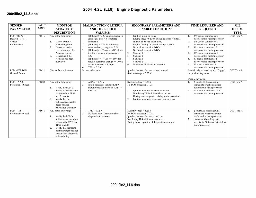
DESCRIPTION VALUE(S) TYPE PCM (MCP) - Desired TP to TP Sensor Performance
P1516 Any of the following: 1. Detect a throttle
positioning error 2. Detect excessive
current draw on the Actuator Circuit
3. Determine if the Actuator has been miswired
1. |TP Error| >=2 % with no change in error sign, after > 5 sec stable command
2. |TP Error| >=2 % for a throttle command step change >= |2 %|
3. |TP Error| >=+7% or <= -10% for a throttle command step change >= |5%|
4. |TP Error| >=+7% or <= -10% for throttle command change >= |10 %|
5. Actuator current > 9 amps 6. TPS1 < 3.6 V
1. Ignition in run or crank Engine speed >0 RPM or engine speed = 0 RPM and not in battery saver mode Engine running or system voltage > 8.0 V No airflow actuation DTCs No throttle actuation DTCs
2. Same as 1 3. Same as 1 4. Same as 1 5. Same as 1 6. Minimum TPS learn active state
1. 249 counts continuous, 2 msec/count in motor processor
2. 249 counts continuous, 2 msec/count in motor processor
3. 99 counts continuous, 2 msec/count in motor processor
4. 149 counts continuous, 2 msec/count in motor processor
5. 49 counts continuous, 2 msec/count in motor processor
6. 99 count continuous, 2 msec/count in motor processor
DTC Type A
PCM - EEPROM General Failure
P1621 Checks for a write error Incorrect checksum Ignition in unlock/accessory, run, or crank. System voltage > 5.23 V
Immediately on next key up if flagged on previous key down Once at key down
DTC Type A
PCM – APPS Performance Check
P1680 Any of the following: 1. Verify the PCM’s
ability to detect a short between the APPS1 and 2 circuits
2. Verify that the indicated accelerator pedal position calculation is correct
1. APPS2 > 1.75 V 2. | Main processor indicated APP –
motor processor indicated APP | > 0.142 V
System voltage > 5.23 V No PCM processor DTCs 1. Ignition in unlock/accessory and run
Not during TPS minimum learn active During intusive portion of diagnostic execution
2. Ignition in unlock, accessory, run, or crank
1. 2 counts, 154 msec/count, immediate retest on an error performed in main processor
2. 25 counts continuous, 15.6 msec/count in motor processor
DTC Type A
PCM - TPS Performance Check
P1681 Any of the following: 1. Verify the PCM’s
ability to detect a short between the TPS1 and TPS2 circuits
2. Verify that the throttle control system position sensor short diagnostic is functioning
1. TPS2 > 1.75 V 2. No detection of the sensor short
diagnostic active state
System voltage > 5.23 V No PCM processor DTCs Ignition in unlock/accessory and run Not during TPS minimum learn active During intusive portion of diagnostic execution
1. 2 counts, 154 msec/count, immediate retest on an error performed in main processor
2. No sensor short diagnostic activity for 500 msec detected by motor processor
DTC Type A
2004file2_LL8.doc
2004 4.2L (LL8) Engine Diagnostic Parameters 2004file2_LL8.doc
SENSED PARAMETER
FAULT CODE
MONITOR STRATEGY
MALFUNCTION CRITERIA AND THRESHOLD
SECONDARY PARAMETERS AND ENABLE CONDITIONS
TIME REQUIRED AND FREQUENCY
MIL ILLUM.
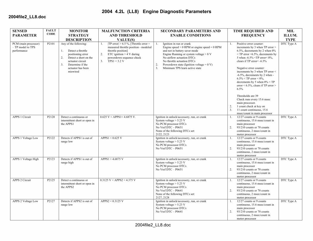
DESCRIPTION VALUE(S) TYPE PCM (main processor) – TP model to TPS performance
P2101 Any of the following: 1. Detect a throttle
positioning error 2. Detect a short on the
actuator circuit 3. Determine if the
actuator has been miswired
1. |TP error| > 6.5 %, [Throttle error = measured throttle position - modeled throttle position]
2. ETC ignition > 4 V during powerdown sequence check
3. TPS1 < 3.2 V
1. Ignition in run or crank Engine speed > 0 RPM or engine speed = 0 RPM and not in battery saver mode Engine Running or system voltage > 8 V No airflow actuation DTCs No throttle actuation DTCs
2. Powerdown state (Ignition voltage = 0 V) 3. Minimum TPS learn active state
1. Positive error counter: increments by 3 when TP error > 6.5%, decrements by 2 when 0% < TP error <6.5%, decrements by 5 when -6.5% <TP error< 0%, clears if TP error< -6.5% Negative error counter: increments by 3 when TP error < -6.5%, decrements by 2 when -6.5% < TP error < 0%, decrements by 5 when 0% < TP error < 6.5%, clears if TP error > 6.5% Thresholds are 39 Check runs every 15.6 msec main processor.
2. 1 count check at key on 3. 11 count continuous, 15.6
msec/count in main processor
DTC Type A
APPS 1 Circuit P2120 Detect a continuous or intermittent short or open in the APPS1
0.625 V < APPS1< 4.6875 V. Ignition in unlock/accessory, run, or crank System voltage > 5.23 V No PCM processor DTCs No Vref DTC – P0651 None of the following DTCs set: 2122, 2123
1. 12/27 counts or 9 counts continuous, 15.6 msec/count in main processor
2. 93/210 counts or 70 counts continuous, 2 msec/count in motor processor
DTC Type A
APPS 1 Voltage Low P2122 Detects if APPS1 is out of range low
APPS1 < 0.625 V Ignition in unlock/accessory, run, or crank System voltage > 5.23 V No PCM processor DTCs No Vref DTC – P0651
1. 12/27 counts or 9 counts continuous, 15.6 msec/count in main processor
2. 93/210 counts or 70 counts continuous, 2 msec/count in motor processor
DTC Type A
APPS 1 Voltage High P2123 Detects if APPS1 is out of range high
APPS1 > 4.6875 V Ignition in unlock/accessory, run, or crank System voltage > 5.23 V No PCM processor DTCs No Vref DTC – P0651
1. 12/27 counts or 9 counts continuous, 15.6 msec/count in main processor
2. 93/210 counts or 70 counts continuous, 2 msec/count in motor processor
DTC Type A
APPS 2 Circuit P2125 Detect a continuous or intermittent short or open in the APPS2
0.3125 V < APPS2 < 4.375 V Ignition in unlock/accessory, run, or crank System voltage > 5.23 V No PCM processor DTCs No Vref DTC – P0641 None of the following DTCs set: 2127, 2128
1. 12/27 counts or 9 counts continuous, 15.6 msec/count in main processor
2. 93/210 counts or 70 counts continuous, 2 msec/count in motor processor
DTC Type A
APPS 2 Voltage Low P2127 Detects if APPS2 is out of range low
APPS2 < 0.3125 V Ignition in unlock/accessory, run, or crank System voltage > 5.23 V No PCM processor DTCs No Vref DTC – P0641
1. 12/27 counts or 9 counts continuous, 15.6 msec/count in main processor
2. 93/210 counts or 70 counts continuous, 2 msec/count in motor processor
DTC Type A
2004file2_LL8.doc
2004 4.2L (LL8) Engine Diagnostic Parameters 2004file2_LL8.doc
SENSED PARAMETER
FAULT CODE
MONITOR STRATEGY
MALFUNCTION CRITERIA AND THRESHOLD
SECONDARY PARAMETERS AND ENABLE CONDITIONS
TIME REQUIRED AND FREQUENCY
MIL ILLUM.
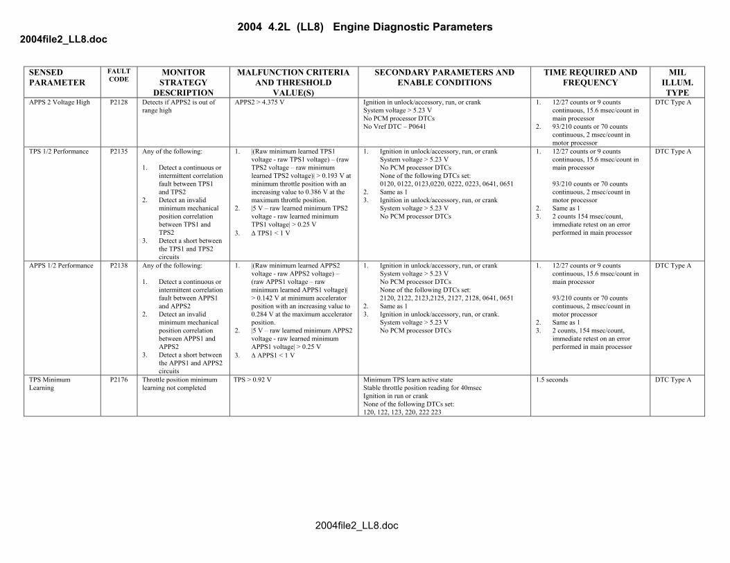
DESCRIPTION VALUE(S) TYPE APPS 2 Voltage High P2128 Detects if APPS2 is out of
range high APPS2 > 4.375 V Ignition in unlock/accessory, run, or crank
System voltage > 5.23 V No PCM processor DTCs No Vref DTC – P0641
1. 12/27 counts or 9 counts continuous, 15.6 msec/count in main processor
2. 93/210 counts or 70 counts continuous, 2 msec/count in motor processor
DTC Type A
TPS 1/2 Performance P2135 Any of the following: 1. Detect a continuous or
intermittent correlation fault between TPS1 and TPS2
2. Detect an invalid minimum mechanical position correlation between TPS1 and TPS2
3. Detect a short between the TPS1 and TPS2 circuits
1. |(Raw minimum learned TPS1 voltage - raw TPS1 voltage) – (raw TPS2 voltage – raw minimum learned TPS2 voltage)| > 0.193 V at minimum throttle position with an increasing value to 0.386 V at the maximum throttle position.
2. |5 V – raw learned minimum TPS2 voltage - raw learned minimum TPS1 voltage| > 0.25 V
3. ∆ TPS1 < 1 V
1. Ignition in unlock/accessory, run, or crank System voltage > 5.23 V No PCM processor DTCs None of the following DTCs set: 0120, 0122, 0123,0220, 0222, 0223, 0641, 0651
2. Same as 1 3. Ignition in unlock/accessory, run, or crank
System voltage > 5.23 V No PCM processor DTCs
1. 12/27 counts or 9 counts continuous, 15.6 msec/count in main processor 93/210 counts or 70 counts continuous, 2 msec/count in motor processor
2. Same as 1 3. 2 counts 154 msec/count,
immediate retest on an error performed in main processor
DTC Type A
APPS 1/2 Performance P2138 Any of the following: 1. Detect a continuous or
intermittent correlation fault between APPS1 and APPS2
2. Detect an invalid minimum mechanical position correlation between APPS1 and APPS2
3. Detect a short between the APPS1 and APPS2 circuits
1. |(Raw minimum learned APPS2 voltage - raw APPS2 voltage) – (raw APPS1 voltage – raw minimum learned APPS1 voltage)| > 0.142 V at minimum accelerator position with an increasing value to 0.284 V at the maximum accelerator position.
2. |5 V – raw learned minimum APPS2 voltage - raw learned minimum APPS1 voltage| > 0.25 V
3. ∆ APPS1 < 1 V
1. Ignition in unlock/accessory, run, or crank System voltage > 5.23 V No PCM processor DTCs None of the following DTCs set: 2120, 2122, 2123,2125, 2127, 2128, 0641, 0651
2. Same as 1 3. Ignition in unlock/accessory, run, or crank.
System voltage > 5.23 V No PCM processor DTCs
1. 12/27 counts or 9 counts continuous, 15.6 msec/count in main processor 93/210 counts or 70 counts continuous, 2 msec/count in motor processor
2. Same as 1 3. 2 counts, 154 msec/count,
immediate retest on an error performed in main processor
DTC Type A
TPS Minimum Learning
P2176 Throttle position minimum learning not completed
TPS > 0.92 V Minimum TPS learn active state Stable throttle position reading for 40msec Ignition in run or crank None of the following DTCs set: 120, 122, 123, 220, 222 223
1.5 seconds DTC Type A
2004file2_LL8.doc