
2002.Bhasin Johansen Barton Makurat RockJointSealingExperimentsUsingUltraFineCementGrout
7
North American Tunnelling 2002, Ozdemir (ed.) 2002 Swets & Zeitlinger, Lisse, ISBN 90 5809 376 X 257 1 INTRODUCTION In many cases water leakages are governed by flow along the joints. An understanding of how the groundwater moves in rocks is one of the most im- portant factors in the solution of rock engineering problems. This is especially true with regards to the planning and design of tunnels, storage caverns and underground waste disposals. Concerning nuclear waste repository safety a key aspect is the confidence of being able to successfully seal underground exca- vations and demonstrate methods of reducing the permeability of adjacent rock by sealing joints and fissures. This paper describes the laboratory sealing ex- periments conducted on rock joints using a unique testing equipment designed by NGI. The equipment, called coupled shear flow temperature testing (CSFT) apparatus, has basically been used to derive the experimental data needed to quantify the effect of joint deformation on joint conductivity (Fig. 1). With the CSFT apparatus, joints can be closed, sheared and dilated under controlled normal stress conditions and at the same time cold or hot fluids can be flushed through the joint. Deformations, flow rate and stresses are recorded simultaneously. The CSFT test is designed to simulate as closely as pos- sible the in situ state of critical joints and its modifi- cation by increases or decreases in normal and/or shear stress. In the present series of tests cement grout mixture was injected in the joint samples with increasing injection pressures. The rate of grout flow and the injection pressure versus time were recorded simultaneously to study the penetrability of a grout. 2 PENETRATION POTENTIAL OF GROUT MIXES From a rheological point of view, a grout mix corresponds to a Bingham body exhibiting both cohesion and viscosity. A stable grout mix is defined as a mix having virtually no sedimentation e.g. less than 5% sedimentation in 2 hours (Lombardi, 1985). Water on the other hand follows Newton’s law and is therefore a Newtonian body due to its viscosity and its lack of cohesion. A Newtonian fluid is represented by the following equation: dx dv (1) where τ=shear stress (Pa); η= kinematic viscosity (Pasec), dv/dx= strain rate (sec -1 ) A Bingham body or a stable mix is represented by the following equation: dx dv c (2) where c= cohesion (Pa) Rock joint sealing experiments using an ultra fine cement grout Rajinder Bhasin Norwegian Geotechnical Institute, Oslo Per Magnus Johansen Norconsult AS, Oslo Nick Bar ton Nick Barton and Associates, Oslo Axel Makurat Shell International Exploration and Production, The Netherlands ABSTRACT: Rock joint sealing experiments have been conducted in a laboratory using a bi-axial coupled shear- flow test apparatus (CSFT). The laboratory test programme was designed to investigate the penetrative potential of a grout using different water/ce ment ratios on joints having differe nt joint roughness (JRC) and joint conducting aperture in different stress condition s (total normal stress, joint water pressure and grouting pressure ). The results indi cate that joint s with a conducting apert ure (e) as small as approximatel y 25 microns can be grouted using a stable mixture of superfine cement, water and a super plasticizer (dispersing agent). The penetration capacity of a specific cement grout depends, in addition to the joint’s characteristics, on the maximum grain size, the water/cement ratio and the injection pressure used. The tests reveal that the mini- mum physical aperture (E) that can be grouted corresponds to approximately four times the cement’s maxi- mum grain size.
-
Upload
gabrenogue -
Category
Documents
-
view
221 -
download
0
Transcript of 2002.Bhasin Johansen Barton Makurat RockJointSealingExperimentsUsingUltraFineCementGrout
8/9/2019 2002.Bhasin Johansen Barton Makurat RockJointSealingExperimentsUsingUltraFineCementGrout
http://slidepdf.com/reader/full/2002bhasin-johansen-barton-makurat-rockjointsealingexperimentsusingultrafinecementgrout 1/6
North American Tunnelling 2002, Ozdemir (ed.)
2002 Swets & Zeitlinger, Lisse, ISBN 90 5809 376 X
257
1 INTRODUCTION
In many cases water leakages are governed by
flow along the joints. An understanding of how thegroundwater moves in rocks is one of the most im- portant factors in the solution of rock engineering problems. This is especially true with regards to the planning and design of tunnels, storage caverns andunderground waste disposals. Concerning nuclear waste repository safety a key aspect is the confidenceof being able to successfully seal underground exca-vations and demonstrate methods of reducing the
permeability of adjacent rock by sealing joints andfissures.
This paper describes the laboratory sealing ex- periments conducted on rock joints using a uniquetesting equipment designed by NGI. The equipment,called coupled shear flow temperature testing(CSFT) apparatus, has basically been used to derivethe experimental data needed to quantify the effectof joint deformation on joint conductivity (Fig. 1).With the CSFT apparatus, joints can be closed,sheared and dilated under controlled normal stressconditions and at the same time cold or hot fluidscan be flushed through the joint. Deformations, flow
rate and stresses are recorded simultaneously. TheCSFT test is designed to simulate as closely as pos-sible the in situ state of critical joints and its modifi-cation by increases or decreases in normal and/or shear stress. In the present series of tests cement
grout mixture was injected in the joint samples withincreasing injection pressures. The rate of grout flowand the injection pressure versus time were recorded
simultaneously to study the penetrability of a grout.
2 PENETRATION POTENTIAL OF GROUTMIXES
From a rheological point of view, a grout mixcorresponds to a Bingham body exhibiting bothcohesion and viscosity. A stable grout mix is definedas a mix having virtually no sedimentation e.g. lessthan 5% sedimentation in 2 hours (Lombardi, 1985).Water on the other hand follows Newton’s law and
is therefore a Newtonian body due to its viscosityand its lack of cohesion. A Newtonian fluid isrepresented by the following equation:
dxdv (1)
where τ=shear stress (Pa); η= kinematic viscosity(Pasec), dv/dx= strain rate (sec
-1)
A Bingham body or a stable mix is represented bythe following equation:
dxdv c (2)
where c= cohesion (Pa)
Rock joint sealing experiments using an ultra fine cement grout
Rajinder Bhasin Norwegian Geotechnical Institute, Oslo
Per Magnus Johansen Norconsult AS, Oslo
Nick Barton Nick Barton and Associates, Oslo
Axel MakuratShell International Exploration and Production, The Netherlands
ABSTRACT: Rock joint sealing experiments have been conducted in a laboratory using a bi-axial coupledshear- flow test apparatus (CSFT). The laboratory test programme was designed to investigate the penetrative
potential of a grout using different water/cement ratios on joints having different joint roughness (JRC) and joint conducting aperture in different stress conditions (total normal stress, joint water pressure and grouting
pressure). The results indicate that joints with a conducting aperture (e) as small as approximately 25 micronscan be grouted using a stable mixture of superfine cement, water and a super plasticizer (dispersing agent).The penetration capacity of a specific cement grout depends, in addition to the joint’s characteristics, on themaximum grain size, the water/cement ratio and the injection pressure used. The tests reveal that the mini-mum physical aperture (E) that can be grouted corresponds to approximately four times the cement’s maxi-mum grain size.

8/9/2019 2002.Bhasin Johansen Barton Makurat RockJointSealingExperimentsUsingUltraFineCementGrout
http://slidepdf.com/reader/full/2002bhasin-johansen-barton-makurat-rockjointsealingexperimentsusingultrafinecementgrout 2/6258
Unstable mixes of cement and water will showintermediate rheological properties compared to thetwo cases mentioned above.
By decreasing the water content in the mix, either bydecreasing the initial water-cement ratio or by loss of excess water during grouting, the mix may be so drythat it will have an internal friction angle and the
rheological law of such a body will be (Lombardi,1985):
tan pdxdvc (3)
where τ= shear stress (Pa); c= cohesion (Pa);η= kinematic viscosity (Pas), dv/dx= strain rate
(1/s), p= internal pressure (Pa), = internal frictionangle ()
Even if the internal friction angle is assumed to besmall in such a mix the potential travel distance will
be only a fraction of that of a Bingham body for agiven pressure gradient and joint aperture. This mixwill form a "plug" in a joint at a very short distancefrom the grout hole (or even in the grout pipes or hole itself).
This form of "plugging" or "pressure filtration" mayoccur even with a thin, unstable grout. Grouts withhigh water content and low viscosities are thought tohave higher penetrative potential than the thicker mixes - the limit being the grain size of the groutcompared to the joint opening, and the setting
ability. When the larger grains become stuck in the joints, the gradient and pressure drop across this plugincreases and the excess water will be pressed out of suspension. Penetration tests on natural or artificial
joints have been performed by several authors usingdifferent cement and/or bentonite based suspensions(see e.g. Ran and Daemen, 1992, Widman, 1991 andHåkansson et al. 1992). It is a general opinion thatcement grout suspensions may penetrate rock jointswith an aperture varying from about of 0.1 to0.5mm.
Figure 1 NGI’s biaxial apparatus for CSFT testing of joints
3 PROPERTIES OF THE GROUT USED
In the present rock joint sealing experiments an ultrafine cement grout, in which 98% of the material wasfiner than 12 microns, has been used to study the
penetrative potential of grout mixes with differentwater cement ratios. The grout mixture comprised of cement (Spinor A), tap water and dispersing agent
(Mighty 150). The dispersing agent (correspondingto 2% of the weight of cement) was added to thewater and mixed for 1 minute. Then the water andcement was carefully mixed by hand before the groutwas thoroughly mixed for approximately 10 minutesusing an ULTRA-TURRAX T25 mixer with a17mm diameter rotor. The rotor speed was set at8000 rpm and gradually increased to 24000 rpm.The injection test was started immediately after themixture was prepared in order to avoid any harden-ing of the grout.
A Marsh funnel calibrated to an outflow of one quart(946 cm3) of fresh water at a temperature of ap-
proximately 21C per 26 seconds was used to meas-ure the viscosity of the grout at different wa-ter/cement ratios. Table 1 shows the results of thetests at water/cement ratios of 0.6, 0.8 and 1.0; withand without a dispersing agent.
A sample of each mixture was cured under cover.The apparent bleed of the grout mixture with thedispersing agent was considered as negligible and no
cracking was observed in the cured samples.
Table 1 Results of Marsh Funnel Tests on Grout Mixtures
______________________________________________ Water/Cement Time, Seconds _________________________
Ratio Dispersing agent No dispersing agent ______________________________________________ 0.6 38.9
0.8 31.5 46.31.0 28.9 36.8- _____________________________________________ Water 26 _____________________________________________
4 DESCRIPTION OF ROCK JOINT SAMPLES
Three different rock joint samples were used for in- jection testing in the CSFT apparatus. The jointsamples were procured from the field in mated con-dition and were prepared such that the horizontallength of the joint plane was around 85 mm. All thesamples were characterised and profiled using themethod described by Barton and Choubey, 1977.Table 2 shows the joint characterisation of the indi-
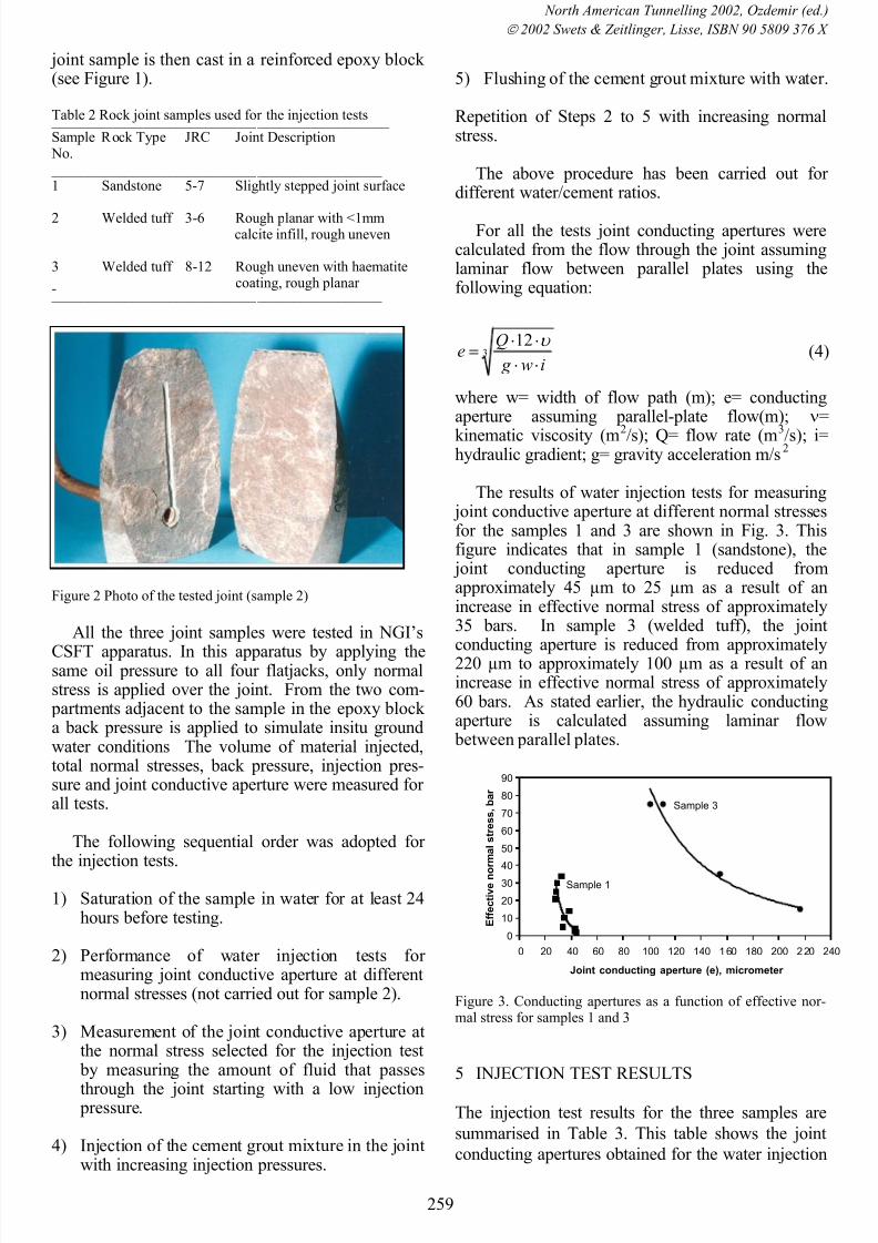
vidual samples. Figure 2 shows a rock joint sample(sample 2) used for the injection tests. In one of the parts of the sample a hole of approximately 15 mmdiameter is bored through the sample to facilitateinjection of the grout mixture. The re-assembled
8/9/2019 2002.Bhasin Johansen Barton Makurat RockJointSealingExperimentsUsingUltraFineCementGrout
http://slidepdf.com/reader/full/2002bhasin-johansen-barton-makurat-rockjointsealingexperimentsusingultrafinecementgrout 3/6
North American Tunnelling 2002, Ozdemir (ed.)
2002 Swets & Zeitlinger, Lisse, ISBN 90 5809 376 X
259
joint sample is then cast in a reinforced epoxy block (see Figure 1).
Table 2 Rock joint samples used for the injection tests ______________________________________________ Sample Rock Type JRC Joint Description
No. _____________________________________________ 1 Sandstone 5-7 Slightly stepped joint surface
2 Welded tuff 3-6 Rough planar with <1mmcalcite infill, rough uneven
3 Welded tuff 8-12 Rough uneven with haematitecoating, rough planar - _____________________________________________
Figure 2 Photo of the tested joint (sample 2)
All the three joint samples were tested in NGI’s
CSFT apparatus. In this apparatus by
applying thesame oil pressure to all four flatjacks, only normalstress is applied over the joint. From the two com-
partments adjacent to the sample in the epoxy block a back pressure is applied to simulate insitu groundwater conditions The volume of material injected,total normal stresses, back pressure, injection pres-sure and joint conductive aperture were measured for all tests.
The following sequential order was adopted for the injection tests.
1) Saturation of the sample in water for at least 24hours before testing.
2) Performance of water injection tests for measuring joint conductive aperture at differentnormal stresses (not carried out for sample 2).
3) Measurement of the joint conductive aperture atthe normal stress selected for the injection test
by measuring the amount of fluid that passes
through the joint starting with a low injection pressure.
4) Injection of the cement grout mixture in the jointwith increasing injection pressures.
5) Flushing of the cement grout mixture with water.
Repetition of Steps 2 to 5 with increasing normalstress.
The above procedure has been carried out for different water/cement ratios.
For all the tests joint conducting apertures werecalculated from the flow through the joint assuminglaminar flow between parallel plates using thefollowing equation:
312
iw g
Qe
(4)
where w= width of flow path (m); e= conductingaperture assuming parallel-plate flow(m); =
kinematic viscosity (m2
/s); Q= flow rate (m3
/s); i=hydraulic gradient; g= gravity acceleration m/s
2
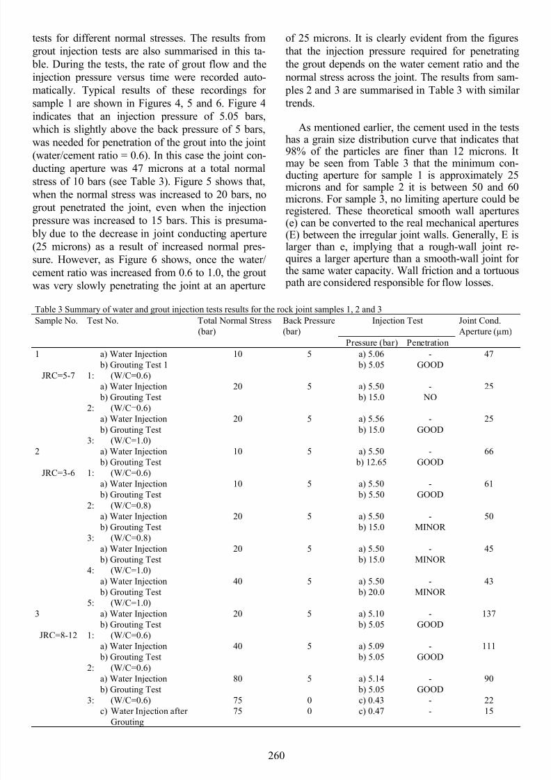
The results of water injection tests for measuring joint conductive aperture at different normal stressesfor the samples 1 and 3 are shown in Fig. 3. Thisfigure indicates that in sample 1 (sandstone), the
joint conducting aperture is reduced fromapproximately 45 µm to 25 µm as a result of anincrease in effective normal stress of approximately35 bars. In sample 3 (welded tuff), the joint
conducting aperture is reduced from approximately220 µm to approximately 100 µm as a result of anincrease in effective normal stress of approximately60 bars. As stated earlier, the hydraulic conductingaperture is calculated assuming laminar flow
between parallel plates.
Figure 3. Conducting apertures as a function of effective nor-mal stress for samples 1 and 3
5 INJECTION TEST RESULTS
The injection test results for the three samples are
summarised in Table 3. This table shows the joint
conducting apertures obtained for the water injection
0
10
20
30
40
50
60
70
80
90
0 20 40 60 80 100 120 140 160 180 200 220 240
Joint conducting aperture (e), micrometer
E f f e c t i v e n o
r m a l s t r e s s ,
b a r
Sample 1
Sample 3
8/9/2019 2002.Bhasin Johansen Barton Makurat RockJointSealingExperimentsUsingUltraFineCementGrout
http://slidepdf.com/reader/full/2002bhasin-johansen-barton-makurat-rockjointsealingexperimentsusingultrafinecementgrout 4/6260
tests for different normal stresses. The results from
grout injection tests are also summarised in this ta-
ble. During the tests, the rate of grout flow and the
injection pressure versus time were recorded auto-
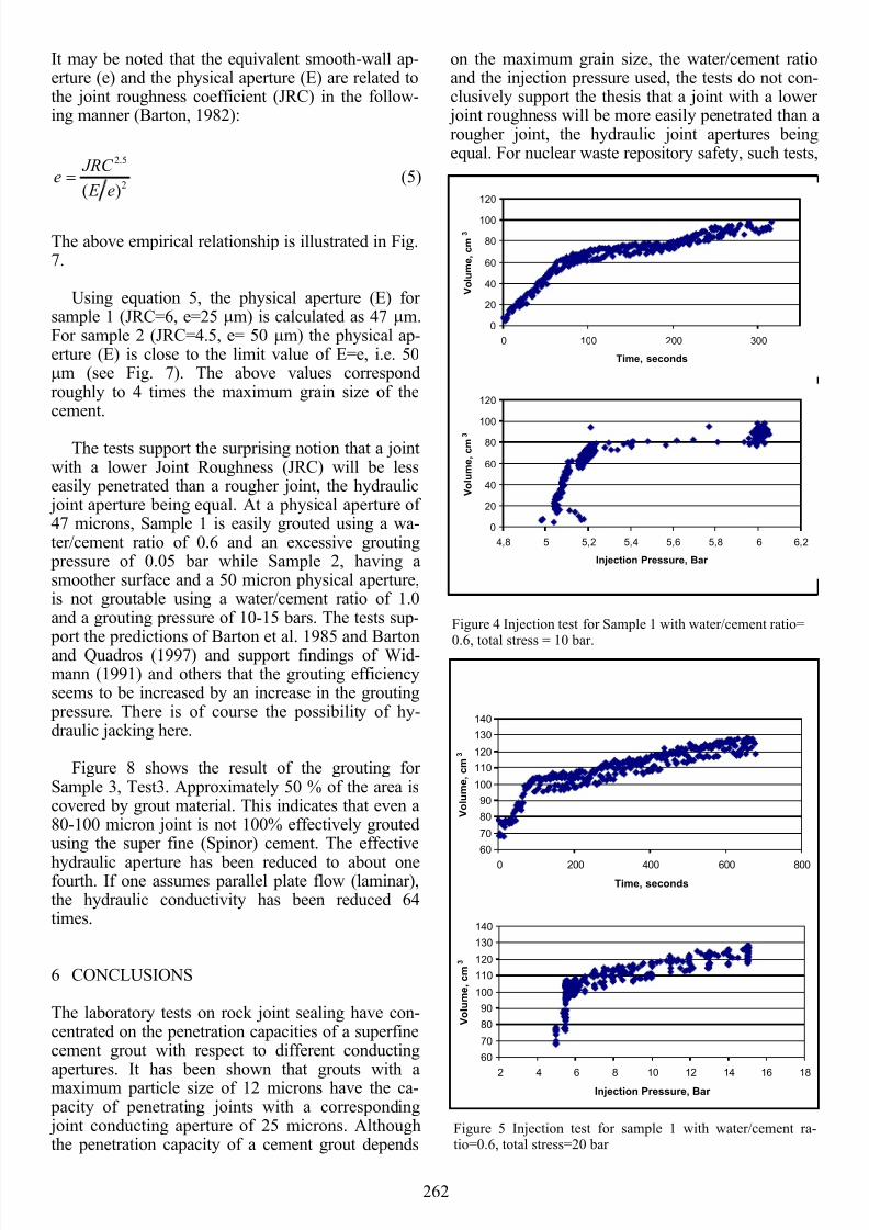
matically. Typical results of these recordings for
sample 1 are shown in Figures 4, 5 and 6. Figure 4
indicates that an injection pressure of 5.05 bars,
which is slightly above the back pressure of 5 bars,
was needed for penetration of the grout into the joint
(water/cement ratio = 0.6). In this case the joint con-
ducting aperture was 47 microns at a total normal
stress of 10 bars (see Table 3). Figure 5 shows that,
when the normal stress was increased to 20 bars, no
grout penetrated the joint, even when the injection
pressure was increased to 15 bars. This is presuma-
bly due to the decrease in joint conducting aperture
(25 microns) as a result of increased normal pres-
sure. However, as Figure 6 shows, once the water/
cement ratio was increased from 0.6 to 1.0, the groutwas very slowly penetrating the joint at an aperture
of 25 microns. It is clearly evident from the figures
that the injection pressure required for penetrating
the grout depends on the water cement ratio and the
normal stress across the joint. The results from sam-
ples 2 and 3 are summarised in Table 3 with similar
trends.
As mentioned earlier, the cement used in the tests
has a grain size distribution curve that indicates that98% of the particles are finer than 12 microns. Itmay be seen from Table 3 that the minimum con-ducting aperture for sample 1 is approximately 25microns and for sample 2 it is between 50 and 60microns. For sample 3, no limiting aperture could beregistered. These theoretical smooth wall apertures(e) can be converted to the real mechanical apertures(E) between the irregular joint walls. Generally, E islarger than e, implying that a rough-wall joint re-quires a larger aperture than a smooth-wall joint for
the same water capacity. Wall friction and a tortuous path are considered responsible for flow losses.
Table 3 Summary of water and grout injection tests results for the rock joint samples 1, 2 and 3
Sample No. Test No. Total Normal Stress
(bar)
Back Pressure
(bar)
Injection Test Joint Cond.
Aperture (µm)
Pressure (bar) Penetration
1
JRC=5-7
a) Water Injection
b) Grouting Test 1
1: (W/C=0.6)
10 5 a) 5.06
b) 5.05
-
GOOD
47
a) Water Injection
b) Grouting Test
2: (W/C=0.6)
20 5 a) 5.50
b) 15.0
-
NO
25
a) Water Injection
b) Grouting Test
3: (W/C=1.0)
20 5 a) 5.56
b) 15.0
-
GOOD
25
2
JRC=3-6
a) Water Injection
b) Grouting Test
1: (W/C=0.6)
10 5 a) 5.50
b) 12.65
-
GOOD
66
a) Water Injection
b) Grouting Test
2: (W/C=0.8)
10 5 a) 5.50
b) 5.50
-
GOOD
61
a) Water Injection
b) Grouting Test
3: (W/C=0.8)
20 5 a) 5.50
b) 15.0
-
MINOR
50
a) Water Injection b) Grouting Test
4: (W/C=1.0)
20 5 a) 5.50 b) 15.0
-MINOR
45
a) Water Injection
b) Grouting Test
5: (W/C=1.0)
40 5 a) 5.50
b) 20.0
-
MINOR
43
3
JRC=8-12
a) Water Injection
b) Grouting Test
1: (W/C=0.6)
20 5 a) 5.10
b) 5.05
-
GOOD
137
a) Water Injection
b) Grouting Test
2: (W/C=0.6)
40 5 a) 5.09
b) 5.05
-
GOOD
111
a) Water Injection b) Grouting Test
3: (W/C=0.6)
c) Water Injection after
Grouting
80
75
75
5
0
0
a) 5.14 b) 5.05
c) 0.43
c) 0.47
-GOOD
-
-
90
22
15
8/9/2019 2002.Bhasin Johansen Barton Makurat RockJointSealingExperimentsUsingUltraFineCementGrout
http://slidepdf.com/reader/full/2002bhasin-johansen-barton-makurat-rockjointsealingexperimentsusingultrafinecementgrout 5/6262
60
70
80
90
100
110
120
130
140
2 4 6 8 10 12 14 16 18Injection Pressure, Bar
V o l u m e , c m
3
60
70
80
90
100
110
120
130
140
0 200 400 600 800
Time, seconds
V o l u m e , c m
3
It may be noted that the equivalent smooth-wall ap-erture (e) and the physical aperture (E) are related tothe joint roughness coefficient (JRC) in the follow-ing manner (Barton, 1982):
2
5.2
)( e E
JRC e (5)
The above empirical relationship is illustrated in Fig.7.
Using equation 5, the physical aperture (E) for sample 1 (JRC=6, e=25 m) is calculated as 47 m.For sample 2 (JRC=4.5, e= 50 m) the physical ap-erture (E) is close to the limit value of E=e, i.e. 50m (see Fig. 7). The above values correspondroughly to 4 times the maximum grain size of thecement.
The tests support the surprising notion that a jointwith a lower Joint Roughness (JRC) will be lesseasily penetrated than a rougher joint, the hydraulic
joint aperture being equal. At a physical aperture of 47 microns, Sample 1 is easily grouted using a wa-ter/cement ratio of 0.6 and an excessive grouting
pressure of 0.05 bar while Sample 2, having asmoother surface and a 50 micron physical aperture,is not groutable using a water/cement ratio of 1.0and a grouting pressure of 10-15 bars. The tests sup-
port the predictions of Barton et al. 1985 and Bartonand Quadros (1997) and support findings of Wid-mann (1991) and others that the grouting efficiencyseems to be increased by an increase in the grouting
pressure. There is of course the possibility of hy-draulic jacking here.
Figure 8 shows the result of the grouting for Sample 3, Test3. Approximately 50 % of the area iscovered by grout material. This indicates that even a80-100 micron joint is not 100% effectively groutedusing the super fine (Spinor) cement. The effective
hydraulic aperture has been reduced to about onefourth. If one assumes parallel plate flow (laminar),the hydraulic conductivity has been reduced 64times.
6 CONCLUSIONS
The laboratory tests on rock joint sealing have con-centrated on the penetration capacities of a superfinecement grout with respect to different conducting
apertures. It has been shown that grouts with amaximum particle size of 12 microns have the ca- pacity of penetrating joints with a corresponding joint conducting aperture of 25 microns. Althoughthe penetration capacity of a cement grout depends
on the maximum grain size, the water/cement ratioand the injection pressure used, the tests do not con-clusively support the thesis that a joint with a lower
joint roughness will be more easily penetrated than arougher joint, the hydraulic joint apertures beingequal. For nuclear waste repository safety, such tests,
Figure 4 Injection test for Sample 1 with water/cement ratio=
0.6, total stress = 10 bar.
0
20
40
60
80
100
120
0 100 200 300
Time, seconds
V o l u m e , c m
3
0
20
40
60
80
100
120
4,8 5 5,2 5,4 5,6 5,8 6 6,2
Injection Pressure, Bar
V o l u m e , c m
3
Figure 5 Injection test for sample 1 with water/cement ra-tio=0.6, total stress=20 bar

8/9/2019 2002.Bhasin Johansen Barton Makurat RockJointSealingExperimentsUsingUltraFineCementGrout
http://slidepdf.com/reader/full/2002bhasin-johansen-barton-makurat-rockjointsealingexperimentsusingultrafinecementgrout 6/6