20000-Cooling Steering Exhaust P2rrtechnical.info/sz/sz87/n1.pdf · Steering system Contents...
20
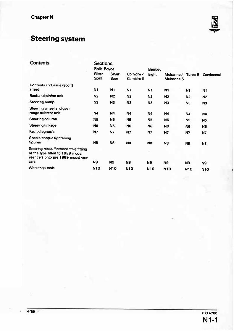
Chapter N Steering system Contents Contents and issue record sheet Rack and pinion unit Steering pump Steering wheel md gear range selector unit Steering column Steering linkage Fau It diagnosis Special torque tightening figures Steering racks. Retrospective Wing of the type fitted to f 989 model year cars onto pre 1989 model year ears Workshop tools Sections Rolls-Rayoe Silver Silver Spirit Spur Bentley Eight Mulsanne/ Turbo R Cantinental MuIsanne S
Transcript of 20000-Cooling Steering Exhaust P2rrtechnical.info/sz/sz87/n1.pdf · Steering system Contents...
Chapter N
Steering system
Contents
Contents and issue record sheet
Rack and pinion unit
Steering pump
Steering wheel md gear range selector unit
Steering column
Steering linkage
Fau It diagnosis
Special torque tightening figures
Steering racks. Retrospective Wing of the type fitted to f 989 model year cars onto pre 1989 model year ears
Workshop tools
Sections Rolls-Rayoe Silver Silver Spirit Spur
Bentley Eight Mulsanne/ Turbo R Cantinental
MuIsanne S

Issue record sheet The dates quoted below refer to the issue date of individual pages within this chapter.
1 I I I l I l I ! I I 4/89 ' TSD 4700

Section N2
TP
Rack and pinion unit
1987 and 1988 model years
fntroduction The steering unit is a rack and pinion power assisted mechanism with centre connection to 'onepiece' track rods. Toe-in can be set by the movement of an intermediate adjuster linking the track rod inner and outer components. An anti-joggle valve is fitted into the hydraulic pressure line (located in the spool valve housing), to minimise any feedback to the steering wheel caused by road irregularities. The steering rack is fitted with internal lock stops. Important Damage can be caused to the steering
column and rack boots if the steering is
operated without the engine running, i.e. distortion to the column, broken column mounts, and cut rack boots.
To overhaul the rack and pinion assembly, the following kits of parts are available.
Spool valve renewal kit Rack overhaul kit Bellows replacement kit.
Power asistanec Pressure is applied tothe steering system rack in varying degrees. This provides assistance to the steering wheel, dependent on the effort required to move the road wheels.
Fig. N2-1 Steering unit mounted in sub-frame 1 Intermediate link 5 Side steering lever 2 Spool valve and pinion 6 Track rod adjuster 3 Convoluted seals 7 Inner ball joint bracket 4 Steering to sub-frame attachment 8 Centre tube and seal

The amount of assistance is controlled by the passage or restriction of oil through a series of ports in the upper half ofthe pinion box. This creates a pressure differential across the rack, proportional to the toad applied at the steering wheel.
The system operates by causing a small torsion bar to twist, immediately the steering wheel is moved. rotating the concentric valve components to provide the pressure differential required. A 'fail safe' device prevents the torsion bar from being overstressed by limiting the number of degrees through which it can twist.
Important The steering unit must be handled with exceptional care. Avoid impact loads on the input shaft and centre off-take, and damage to the convoiuted seals which could cause premature failure of the unit.
Do not disturb the end plug or locking nut whilst the rack and pinion unit is fitted to the car.
Fig. NZ-2 1 2 3 4 5 6 7 8 9
10
Spool valve and pinion housing Bolt - lower link to spline Valve and pinion shaft Heatshield Hydraulic feed pipework Fluid feed to end of rack Anti-joggle valve adapter Hydraulic return pipework Fluid feed to end of 'rack Seal attachment clip Convoluted neoprene seal
The majority of the threads on the rack assembly are metric, except for the mounting bofts to the sub-frame and the lower steering column linkage. Therefore, always ensure the correct nuts and bolts are fitted.
Rack and pinion unit - To remove l . Place the car on a ramp and remove fuse A6 from fuse panel F2 on the main fuseboard.
Disconnect the battery. 2. Chock the road wheels and raise the ramp to a convenient working height 3. fit a clamp to the feed hose from the remote reservoir. 4. Position drip trays beneath the spool valve. Then, remove the pipe unions from the valve.
Fit blanks to prevent the ingress of foreign matter. 5. Remove the split pin, castetlated nut, and bolt securing the lower linkage to the pinion shaft sptines (see fig. NZ-2). 6 Straighten the tab-washer. Then, remove the setscrews holding the inner ball joint bracket to the steering rack centre position. Care must be taken not to disturb the steering rack centre block oil seal. 7. Support the rack and pinion unit, then remove the setscrews attaching the unit to the sub-frame brackets. 8. Lowerthe unit from beneath the suspension, carefully withdrawing the pinion shaft from the lower column linkage. Warning Never strike the rack and pinion unit with a
hammer. 9. Examine the convoluted seals for damage, etc.. and the centre block oil seal for leaks.
Replacement of canvdrrted seals {see fig. NZ-4) If when a convoluted seal is removed due to splits andlor leakage, and there is evidence of the ingress of water and/or road dirt, a complete stripdown, clean, and inspection should be made of the unit. 1. Position drip trays under the ends and centre sections ofthe unit. 2. Carefully remove the hydraulic pipe union situated at the end of the unit, oppogite the pinion box housing. 3. Grip the bracket. at the same end, in a vice. Unscrew and remove the blanking plug from the end of the racktube and withdrawthe outertube from the bracket. Collect the dismantled parts and cover with a clean cloth. Discard the '0' rings.
If it is only necessary to replace the convoluted sear at the dismantled end of the unit. there will be no need to disturb the centre block and oil seal. However, if both convoluted seals are to be removed, the central block and seal must be removed as described in the following operations. 4. Unscrew the capscrew holding the central block in position against the rack gear, withdrawthe block and oi! seal. Protect the components by covering with a clean cloth. 5. Slackenthe sealing clips screws that secure the convoluted seals in position.

Remove the ring clips, seals, and central spacer tube. The spacerrube must be covered to prevent the ingress of dirt. 6. Turn the unit over with the slot facing downwards. This will enable the lubricating oil to drain from the unit into a suitable tray. 7. Fit new convoluted seals. clipping these to the pinion box, outertube, and the central spacer tube.
To enable sewice inspection checks on the tightness of the clips when the unit is fitted to the vehicle, ensure that the screw heads of all the retaining clips face downwards and towards the rear of the rack.
Liftthe unit higher at the dismantled end and pour 0,057 litre (0.7 Imp pt; 0.12 US ptl of new approved lubricating oil (see Chapter D) through the slot in the central spacertube. 8. Fit the centre block using the flexible bonding agent Silastic 732 RTV sealant on the mating surfaces of the seal, to ensure a leak free joint. 9. Fit a new '0' ring and position the support bracket onto the outertube. Apply Loctite 542 to the threads of the blanking plug, and fit a new '0' ring. Carefully screw the blanking plug into position. Note To ensure control of the parallelism of the two
mounting bracket faces, place the assembled unit wRh the bracket face downwards onto a suiface table or a similar flat fixture plate.
'10. tightly clamp thetwo mounting brackets of the unit onto the flat surface. 11. Torque tighten the blanking plug to the figures quoted in Section NB. 12. Screw the hydraulic pipe union into the blanking- plug. Torque tighten to the figures quoted in Section N8.
Rack and pinion unit - f a dismantle (see figs. N2-8 and NZ-91 If the unit has an internal fault which necessitates the removal of the rack. dismantling to thestage of withdrawing the centre blockshould be completed before carrying out the following operations. Removal of the centre block is described under the heading Replacement of convoluted seals, Operations 1 to 6 inclusive. 1. After draining the lubricating oil, place the unit onto two 'Vee' shaped wooden blocks. 2. Remove the remaining feed pipe. Blank offthe hole in the pinion box and cover. 3. Mark the relationship between the input shaft spline and pinion box housing with thesteering in the straight ahead position. Use the screwed plug to ensure a correct setting. 4. Unscrew the nuts, and release the pinion and valve housing assembly by gripping the pinion spline with one hand, and keeping theiwo halves of the valve housing together with the other hand. With a turning movement lift the assembly using the splined shaft, clear of the pinion position {see fig. N2-5). 5. Release the lock-nut. Unscrew the remaining end cap. Discard the internal '0' ring. 6. Using an appropriate sized wooden dowel,
Fig. N2-3 Steering to sub-frame mounting 1 Sub-frame bracket 2 Steering unit mounting foot 3 Tapping block 4 Pinion housing 5 Track rod adjuster
Remwal of convoluted seals Centre tube Seal Mounting foot '0' rings Blanking plug Fluid feed pipework Cap head socket screw Centre block Shaped seal

wrefulty press the end of the rack untit the P T F E ring and oil seal appear at the pinion box end of the unit. 7. Support the end ofthe rack whilst continuing to wfthdraw it from the tube. Ensure that the rack and tube do not make contact. It is easy to damage the internal surface af the tube and therefore care must be taken during this operation. Also, ensure that the P T F E bearing is not damaged during removal past the centre slot and pinion opening. 8. Inspect all components including the. internal faces of the end caps, oil seals, and P T F E bearing carrier.
Fig. NZ-5 Pinion and spool valve removal 1 Plastic dust cap 2 End cap lock-nul 3 Plastic dust caps 4 Pinion boss sptines 5 Bearing pre-toad shim 6 Bearing carrier 7 Seal clip 8 Pinion pre-load shims 9 Rack centring plug
Wash all metal parts In GenWene or an equivaknt deaning fluid.
Pinion and spool valve housing asembly The pinion and spool valve housing assembly comprises the foilowing main s e ~ e e items. An upper oil seal. P T F E sealing rings, lower oil seat, lower oil seal carrier. '0' rings. paper joint washers, pm%-load shims, and circlips.
Upper oil seal - To replake 1. Carefully lift the housing off the spool valve unit, ensuring that the P T F E rings are not damaged.
Ensure that the pre-load shim situated between the bait race camer and pinion housing is not damaged. 2. Carefully remwe the upper oil seal and '0' ring from the housing and discard. 3. Fit a new upper '0' ring and oil seal ensuring that the sealing lip is pointing downwards (see fig. N2-6). Note This type of seal should be fitted dry. Do not use
any lubricant. 4. Fit the spline cover tool RH 9 120 m r the splines and then lower the housing down onto the spod valve- Ensure that each PT F E ring enters the bore squarely with no pinching of the edges against the bore.
P T F E sealing rings - To replace 1. Carefvlly lift the housing off the spool valve unit, 2. Cut into the P T F E sealing rings with a sharp instrument having a smaller dimension than the width of the groove. Take care not to damage the finely machined surfaces of the spool valve. Use Vee* shaped wooden blocks to support the end diameters during removal of the rings. 3- Inspect the ring g m e s of thevalve pinion. 4. Immerse the new P T F E rings in warm oil prior to fitting onto the applicator RH 91 17. Failure to warm the rings before fitting could cause cracking. 5. Place the tool overthe input shaft spline and adjust until the bottom edge of the tool corresponds with the upper edge of the lowest '0' ring grope. 6. Slide a P T F E sealing ring into the groove. 7. Adjust the tool to fit the remainder of the rings into their respective grooms. 8. Remove the sleeve toof then size the rings by carefully pressing the tool RH 91 18 over the rings to reduce their diameter. 9. Fi the spline cover tool RH 91 20 over the spool valve sptines to protect the upper and lower seals whilst assembling the pinion and spool valve housing. 10. Fit the upper ball race carrier, spacers, and ball bearings. Locate these components by fitting a new circtip. 11. Carefully assemble the pinion and spool valve housing.
Lower oil seal - To replace 1. Carefully remove the housing off the spool valve unit. Avoid damage to the P T F E sealing rings.

2. Remove the carrier and lower seal from the housing. 3. Ptess out the lower oil seal from the carrier. 4. Inspect the carrier far damage. 5. Press a new oil swl into the carrier. Ensure that the lip face of the seat is uppermost. Fit the carrier into the housing. 6. Fit the sptine cover tool RH 91 20 over the spool valve splines to protect the upper and lower seals whilst assembling the pinion and spool valve housing. 7. Fit the upper ball race carrier, spacers, and ball bearings. Locate these components by fitting a new circlip. 8. Carefully assemble the pinion and spool valve housing.
Thrust ball race if the spool valve and pinion unit is dismantled to the srage of inspecting the thrust ball race and it is found necessary to replace any thrust race components, the pre-load torque must be reset.
The following table gives a conversion of the spring balance readings quoted in the text, to a figure for use with Nm (tbf in and kgf m) torque spanner.
To protect the components wrap clear adhesive tape over the spline and spool valve rings.
Spring balance and arm kgf I W 0,0544 0.120 0,272 0.600 0.5 10 1.125 0.820 1.800 0.91 0 2.000 1.130 2.500 1.950 4.300 2,040 4.500
Torque spanner Nm kgf m 0,054 0,0055 0,316 0,0320 0.508 0.0520 0.813 0,0830 0.904 0,0922 1,131 0,f 153 1.943 0,1981 2,034 0.2074
Ibf in 0.480 2.400 4.500 7.200 8.000
10.01 0 1 7 -200 1 8.000
1. Fit the ball race with any new components required and lubricate the assembly with a light application of new approved EP 90 grade oil. Ensure that the oil does not contaminate the area bounded by the two oil seais. 2. Redace the lower oil seal carrier as described in tower oil seal - To replace. 3. If a new lower oil seal has been fitted, first place a new paper gasket onto the face of the lower oil seal carrier. Then place the original stack of shims plus one additional shim of at least 0,254 mm (0.010 in ) thickness onto the carrier.
This additional shim will effectively remove any bearing pre-load when assembly is completed.
Shims are available in the following sizes. 0.063 mm (0.0025 in) 0,127 mm (0.005 in) 0,254 mm (0.01 0 in) 1,270 mm (0.050 in). 4. Remove the adhesive tape from the spool valve st.laft only and wipe the spool valve assembly with a clean lint free cloth. Lightly lubricate the assembly with power steering fluid.
Fig. N2-6 Pinion and spool valve unit 1 Spool valve housing 2 Spline 3 Lip-type oil seal 4 '0' ring 5 Spool valve 6 PTFErings(4) 7 Lower oil seal 8 Torque arm 9 Thrust ball race "
10 Pinion 1 1 Ba!l race carrier 1 2 Re-load shimts)
Do not fit the lower oil seal carrier '0' ring at this stage. 5. Carefully fit the spool valve housing onto the spool valve shaft. Ensure that each P T F E sealing ring enters the bore of the housing squarely with no pinching of the ring edges. Do not use force to assemble. 6. Lightly assemble the housing and carriertogether, using three nuts and bolts. Then rotate the input shaft a number of turns to reduce initial drag. 7. Grip the sub-assembly in a soft jawed vice and fit the torque arm tool RH 9123 tothe input shaftspiine. 8. 1 o measure the pinion seal drag and spool valve

friction use a spring balance. Note the reading required to rotate the input shaft. This should be between 0,016 kgf and 0,08 kgf (0.120 tbf and 0.60 Ibfl.
Ifthe reading is above 0.08 kgf (0.60 Ibf), bearing pre-load may still exist and it will be necessary to M an additional shim.
If after fitting additional shims to the extent that no bearing pre-load exists. i.e. end-float appearing in the spool valve, then some other sourceof tightness such as incorrectly sized PT F E rings could be the cause. 9. Assemble and test the unit again as described in Operations 5 to 8 inciusive, until a figure within the
Fig. h12-7 1 2 3 4 5 6 7 8 9
Anti-joggle valve High pressure fluid Heatshield Spool valve housing Anti-joggle valve Spool valve casting Spring Flap valve
,Adapter Pipe union
limits quoted in Operation 8 have been achieved. 10. Dismantle the spoot valve housing. Then, reduce the shims by one 0,063 mm (0.0025 in) shim.
Cheek that a spring balance reading of 0,570 kgf (1.125 Ibfl is required to rotate the shaft. If this reading is not obtained reduce the shims (one at a time) until the correcr reading is achieved. Important Ensure that this procedure is carried out
correctly othewise excessive pre-load can damage the bearing parts.
11. Remove the spool valve housing to fit an '0' ring into the lower oil seal carrier.
Ensure that paper gaskets are in good condition and fitted at the top and bottom of the shim stack. 12. Lubricate the spoot valve and pinion seals with steering fluid and the upper oil seal with a light coating of molybdenum disulphide grease. '73. Carefully assemble the spool valve housing. 14. Ensure new paper gaskets are fitted to the underside of the ball race carrier and to the steering rack pinion housing face. 15. Fit theoriginal number of shims and carefully fit the complete spool valve assembly into the pinion housing. 16. Ensure thatthe hydraulic pipe connections of the spool valve housing are in the correct relative position. 17. The correlation mark on the input shaft should align with the mark on the spool valve housing when the assembly is fully engaged with the rack in the central position. 18. Torque tig hten the retaining nuts to the figures quoted in Section NB. 19. Replace any rack lubricating oil IEP 90 grade). that may have been last during dismantling, up to the total amount of 0,057 litre (0.1 Imp pt; 0.12 US pt).
AntLjoggle valve (see fig. N2-7) 1. With the steering dismantled remove the anti- joggle valve. 2. Check that the spring and flap are functioning correctly by pressing a probe carefully onto the top of the Rap. Ensure that adequate compression of the assembly occurs and the flap seats correctly. 3. Wash outthe assembly in Genklene or an equivalent cleaning solution. Dry using a controlled jet of dry pressurized air into the male threaded end of the unit only. 4. Fit blanking plugs into each end of the adapter.
Pipe union If the olive which forms the seating of the pipe union is found to be damaged it will be necessary to remove the spool valve housing before it can be renewed. It must be emphasized that cleanliness must be observed when carrying out this procedure.
Rack and pinion unit -To assemble It is essential that the rack should only be removed or replacedfrom the pinion end of the unit. m i s ensures that the P T F E bearings or oil seals are not damaged

by the internal thread of the blanking plug end of the assembly.
At this stage, check the bore of the rack tube for scoring or damage. 1. With the rack unit outofthe tube, fit the scarf jointed P T F E rack bearings into the respective grooves in each end of the rack. 2. Gently press each scarf joint together. Ensure that each gap has an initial (nominal) measurement of 2.03 mm (0.080 in).
In the case where the two ends of the PT F E ring butt together or in the event of a smallerthan nominal gap being observed, it will be necessary to remove the ring and cut one end of the scarf joint until the corregfigure is obtained. 3. Using sizing toots (in the following order) RH 91 14, RH 91 13, and RH 91 12, progressively reduce the diameter of the P T F E bearings until these are a sliding fit in the rack tube.
At this stage ensure thatthe gap at the scarF joint I-las not gone below a minimum of 025 mm 10.010 in). Also ensure that it is positioned so as notto come into contact with the edges of the centre slot when the rack is assembled.
Remove any burrs from the slot. Wipe the area clean before assembly. 4. From the pinion end, press the rackslowly into the tube until the PT F E bearing reaches the mid- position of the centre slot.
Ensure that the bearing is not damaged when .
moving along theslot. 5. With the P T F E bearing visible in the centre slot. lightly lubricate a rack oil seal. Fit the seal through the dot in the tube and using finger pressure, press the seal onto the end groove of the rack. Turn the rack slowly during this operation, to assist in assembly of the seal. 6. Lubricate the other rackoil seal and again using finger pressure fit this seal onto the pinion end growe. 7. Slidethe rack unit stowly into thetube. Ensure that no nipping occurs when the oil seal passes into the closed portion of the tube. The pinion end seal must be manipulated into the tube bythe fingers. 8. Lockthe rackinta the mid-position using centring plug RH 91 19. 9. Manipulate a new '0' ring and fit it into the end cap of the unit. Fit the tock-nut onto the tube. A degree of feel must be applied when screwing on the cap to ensure the '0' ring f i correctly. 10. Allow the end cap to butt against the inner face. Then screw back the cap approximately one full turn to allow for hydraulic pipe alignment. 11. Torque tighten the locknut to the figures quoted in Section N8 using the open ended torque wrench adaptor tool RH 9125. 12. Fit naw convoluted seals as described in Replacement of convoluted seals. 13. Liftthe unit higher atthe dismantled end and pour 0,057 litre (0.1 Imp pt; 0.12 US pt) of new EP 90 'lubricating oil through the slot in the centre sleeve. 14. To set the pinion mesh prcload, ensure new
Fig. W 4 Aegembly of free end components 1 Rack spindle 2 PTFEssal 3 Blanking plug 4 End plug '0' ring 5 ,Tube '0' ring 6 Oil seal
Fig. NZ-9 W m b l y of pinion box end components 1 Rack spindle 2 P T F E seal carrier 3 Lock-nut 4 P T F E sear 5 Oil seal 6 End cap'O8ring 7 End cap
TSD 4700

paper gaskets anefmed to the underside of the bat1 race carrier and to the steering rack pinion housing face. 15. Fit the original shims together with additional shims of approximately 3,80 mm to 5.08 mm (0.150 in to 0.20 in) over the studs of the pinion housing. 16. Carefully assemble the spool valve and pinion unit into the steering rack housing. Ensure that with the rack in the central position, the correlation mark on the input shaft and spool valve housing, align when the pinion is fully engaged in the rack. Finger tighten the retaining nuts. Remove the centring plug RH 91 19. 17. Torque tighten the flange retaining nuts to the figuresquoted in Section N8. Fitthe special arm RH 9123 to the input shaft spiine. Using a spring balance, measure the load required to rotate the input shaft approximately one revolution in each direction from the centre position.
The maximum load necessary to rotate the shaft to overcome both rack seal drag and spool valve friction should be 0,91 kgf 12 Ibf).
If the force required is above this figure, then pinion mesh pre-load is still present. Therefore, additional shims must be fitted between the pinion and rack assembly.
Alternatively, the steering rack PT F E bearings could be incorrectly sized and the rack will have to be withdrawn. Reducethe diameter of the bearings further using sizing tools (in the following order) RH 9114, RH 9113, and RH 91 12. 18. Carefully replace the steering rack ensuring no damage occurs to the PT F E bearings and oil seals. Fit the pinion unit.
Fig. N2-70 Inner ball joint bradtd in position 1 Bracket 2 Tab-washer 3 Centre block seal 4 Castellated nut and split-pin
Topup the system with new lubricating oil, grade EP 90. 19. Using special arm RH 8123 and a spring balance, progressively reduce the number of shimsto give a minimum figure of 1.13 kgf (2.50 lbfl abovethe seal drag and spool valve friction detailed in Operation 17.
The maximum total turning load should not exceed a spring balance reading of 204 kgf (4.50 Ibf).
Example If the total rack drag and spool valve friction is equal to 0,82 kgf I f -80 IW) using a spring batance.then the minimum total load by progressively removing shims will be 082 kgf + 1 ,l3 kgf = 1,95 kgf (1.80IM+ 2.5 tbf =430lbf). 20. Return the rack to the straight-ahead position. Fit the centring plug RH 91 19. 21. Carefully assemble the pinion unit to thesteering rack housing. Ensure that the correlation marks on the input shaft and spool valve housing align when the pinion is fully engaged with the rack. 22. Torque tighten the flange retaining nuts to the figures quoted in Section MS. 23. Fit the centre block using the flexible bonding agent Silastic 732 RTV sealant on the mating surfaces of the seal m ensure a leak free joint. Secure the centre block in position using the socket headed capscrew. 24. Manipulate new '0' rings before they are fitted to the blanking plug and lubricate them with power steering fluid to ensure that they fit correctly into their respective grooves.
Replace the outertube and bracket assembly. 25. Set the two suspension brackets of the assembly squarely onto a surface table and clamp firmly into position. 26. Screw in the blanking plug ta the torque figures quoted in Section N8. 27. Fit the pipe runsfrom the end caps to the pinion valve assembly using the torque figures quoted in Section N8. 28. The unit is now ready for fifting to the car, but do not remove the centring plug at this stage.
Rack and pinion unit- To fit to the sub-frame 1. Position and hold the steering wheel in its central position. Carefully fit the pinion box spline into the lower link universal coupling and support the unit in position. Finger tighten the pinch bolt. 2. Fit the setscrews and washers to the sub-frame brackets tapping blocks (see fig. N2-3). Torque tighten the setscrews to the figures quoted in Section NB, using the special tool arm RH 9122. 3. Align the spacer between the inner k H joint bracket and the steering unit centre blackseal (see fig. N2-10). 4. Fit the new tab-washer and finger tighten the setscrews. Remove the centring plug RH 91 19. 5. Torque tighten the inner ball joint bracket setscrews to the figures quoted in Section N8, carefully checking that the oil seal is not displaced. Lock the tab-washertothe setscrews, avoiding any impact to the unit Also, torque tighten the lower

linkage universal couplings pinch bolt, in accordance with the figures quoted in Section N8. 6. Connect the pipework from the pump and oil cooler to the pinion box, ensuring that the union joints are wiped clean before fitting. Torque tighten in accordance with the figures quoted in Section N8. Note Correct routing of the pipework is essential. 7. Fit the gearchange fuse (fuse A6 on fuse panel F2 on the main fuseboard). 8. Connect the battery.
'1989 model year
Introduction The steering unit is a rack and pinion power assisted mechanism with centre connection to 'one-piece' track rods.Toe-in can be set by the movement of an intermediate adjuster Iinking the track rod inner and outer components. An anti-joggle valve is fitted into the hydraulic pressure line (located in the pinion valve housing),to minimise any feedback to thesteering wheel caused by road irregularities. The steering rack is fmed with internal lockstops.
Important Damage can be caused to the steering columnand rack boots ifthe steering is operatedwithout the engine running, i.e. distortion tothe column, broken cotumn mounts, and cut rack boots.
To overhaul the rack and pinion assembly, the following kits of partsare available.
F inion valve overhaul kit Rack overhaul kit Bellows replacement kit Pinion valve housing replacement kit.
Power assistance Pressure is applied to the steerkg system rack in varying degrees. This provides assistanceto the steering wheei, dependent on the effort required to move the road wheels.
The amount of assistance is controlled by the passage or restriction of oil through a series of ports in the upper half of the pinion box.This creates a pressure differential across the rack, proportional to the load applied atthesteering wheel.
The system operates by causing a small torsion barto twist. immediately the steering wheel is moved,
Fig. N2-11 Steering unit mounted in sub-frame I Steering unit mounting bolts 5 Side steering fever 2 Convolutedseals 6 Track rod adjuster 3 Pinion valve housing 7 Inner ball joint bracket 4 Intermediate linkage 8 Centre tube and seat
TSD 4700
N2-9

rotating the concentricvalve components to provide the pressure differential required. A 'fail safe'dwice preventsrhe torsion barfrom being overstressed by limiting the number of degrees through which it can twist. important The steering unit must be handled with
exceptional care. Avoid impact loads on the input shaft and centre off-take, and damage to the convoluted seals which could cause premature failure ofthe unit.
Do not disturb the end plug or locking nut whilst the rackand pinion unit is fitted to the car.
The majority of the threads on the rackassembly are metric, exceptforthe mounting boltstothesub- frame and the lower steering column linkage. Therefore,always ensurethe correct nutsand bolts are fitted.
Rack and pinion unit-To remove (see fig. N2-12) 1. Place the car on a ramp and remove fuseA6 from fuse panel F2 on the main fuseboard.
Disconnect the battery. 2. Chockthe road wheels and raise the ramp to a convenient working height. 3. Fit a clamp to the feed hose from the remote reservoi r. 4. Position drip trays beneath the pinionvalve. Then,
Fig. NZ-12 1
Pinion and valve housing Setscrew- housing to pinion box assembly Pinion valve spline Hydraulic return pipework Anti-joggle valve adapter Hydraulic feed pipework Feed to end of rack Feed to end of rack Pinion box assembly Seal clip Convoluted seat
remove the pipe unionsfrom the valve housing. Fit blanks to prevent the ingress of foreign matter.
5. Removethe split pin, castellated nut, and bolt securing the lower linkageto the pinion shaft splines. 6. Straighten the tab-washer. Then, remove the setscrews holding the inner ball joint bracket to the steering rack centre position. Care must be taken not to disturb the steering rack centre block oil seal. 7. Supportthe rack and pinion unit, then remove the setscrews attaching the unit to the sub-frame brackets. 8. Lowerthe unit from beneaththe suspension, carefully withdrawing the pinion shaft from the lower column linkage. Warning Never strikethe rack and pinion unit with a
hammer. 9. Examinethe convoluted seals for damage, etc., and the centre blockoilseal for leaks.
Rtplacement of convalutsd -1s {see fig. N2-t 3) If when a convotutedseal is removed (due to splits andlor leakage) there isevidenceof the ingress of water andlor road dirt, a completestripdown, clean, and inspection should be made ofthe unit. Note Wheneverthe steering rack unit is dismantled
either partially orcomptetely, cleanliness is of the utmost importance. Always ensurethat any parts that are dismantled ate cleaned and then covered with a dean cloth to preventthe ingress of foreign matter, etc.
1. Position drip trays under the ends and centre sections of the unit. 2. Carefully remove the banjo bolt hydraulic f i ing from the end of the unitfurthestfrorn the pinion box housing. Discard the sealing washers. 3. Grip the support bracket at that same end, in a vice. Unscrew and remove the blanking plug from the end of the rack tube and withdrawthe outer tube from the bracket.
Collectthe dismantled parts and cover with a clean cloth. Discard the 'U' rings.
If it is only necessaryto replace the convoluted seal at the dismantled end of the unit, there will be no need to disturb the centre block and oil seal. However, if both convoluted seals are to be removed, the centre btock and seal must be removed asfollows. 4. Unscrewthe capscrew holding the central block in position against the rack bar. Withdraw the block and oil seal.
Clean the sealing compound off the block.seal, and spacertube.
Protectthe components by covering with a clean cloth. 5. Removeand discard the dips which secure the convoluted seals. 6. Remove the convoluted seals and the central spacer tube.The slot now exposed in the main tube must be covered to prevent the ingress of foreign matter. 7. Turn the unit over with theslot facing downwards. This will enable the lubricating oil to drain from the unit into a suitable tray. 8. Fit new convoluted seals and the central spacer

tube. Do not tighten the new securing clips at this stage. 9. Fit the centre blockand seal using the flexible sealing agent Wastic 732 RW) on the mating surfaces of the seal to ensure a leak free joint. 10. Fit a new '0' ring in the supporl bracket and assemble the support bracketto the tube. 11. f i t a new '0' ring to the blanking plug. Then, carefully screwthe blanking plug into position. Note To ensure control of the pamllelisrn of the two
mounting bracket faces, place the assembled unit with the bradret mounting faces onto a surface tableora similarflat surface. Lightly ciamp both bracket castings onto the flat surface.
12. Torque tig hten the blanking plug to between 73 Nrn and 80 Nm (7,5 kgf m and 8,1 kgf m; 54 tbfft and 59 Ibf ftl 13, Fit the banjo bolt hydraulicfitting, ensuring new sealing washers arefmed. 14. Ciipthe convoluted sealstothe central spacing tube and the support bracket, using tool number RH 12272. 15. Lfirhe rack unit higher at the pinion end and pour 0,057 litre (0.1 Imp pt; 0.12 US ptl of approved lubricating oil (see Chapter D1 into the convoluted seal. 16. Clipthe convoluted seal tothe pinion box casting, using tool number RH 12212.
Rack and pinion unit-To dismantle (see fig. N2-14) Commence by following the instructions underthe heading, Replacement of convoluted seals, Operations 1 to 7 inclusive. 1. After draining the lubricating oil, placethe unit onto two Vee'shaped wooden blocks. Note Cover the wooden blockswith clean cloths to
ensure complete cleanliness. 2. Remove the remaining feed pipe. Discard the sealing washers. 3. Unscrew the retaining boltsto release the rack slipper coverplate. Remove the coverplate, shirn(s1, paper gaskets, spring. and rackslipper. Rotate the rack bar to aid removal of the rack slipper. 4. Unscrew the three setscrews. Then, release the pinion and valve housing assembly by gripping the pinion sptine, and with a turning movement tih the assembly, using thespiined shaft clear of the pinion housing. Note Do not remove the valve housing from the
pinion at this stage. 5. Release the end cap lock-nut. Unscrewthe end cap and discard the internal 'W ring. 6. 'Using an appropriate sized wooden dowel, carefully pressthe end of the rackuntil the PTFE ring and oil seal appear atthe pinion box end ofthe unit 7. Support the end of the rackwhilst continuing to withdraw itfrom the tube. Ensurethat the rack and tube do not make contact. It iseasy to damagethe internal surface of the tube and therefore care must be taken during this operation. A1~0,ensure that the PYFE bearing is not damaged during remova I past t he centre slot and pinion opening.
Fig. N2-13 1 2 3
4 5 6 7 8
9
Removal of convoluted seals Ftuid feed pipework Convoluted seal Mounting foot 'CS rings Blanking plug Centre tube Capscrew Centre block Shaped seat
8. Inspect all components including the internal faces of the end caps, oil seals, and PTFE bearing carrier. Wash all metal parts in Genklene or an equivalent cleaning fluid.
Pinion and valve housing assembly The pinion and valve housing assembly comprise the following main service items. Upper oil sea!$, PTFE sealing rings, lower oil seal, lower oil seal carrier '0' ring, paper joint washers, pbloadshims, and circlip. Note The upper oil seal is easily damaged by the
splineon the valve. Therefore, it is important that when the valve housing is removedfrorn the pinion and valve assem bty. the splines on the valve are protected with clear adhesive tape.
Also, dismantling and assembly of these twocomponentsshould not be carriedout more timesthan is absolutely necessary.
Upper oil seal-To replace (see fig. N2-15) 7. Carefully tift the housing offthe valve and pinion assembly, ensuring thstthe PTFE rings are not damaged. 2. Remove the upperoil seal and80' ring from the housing, and discard. 3. Fit a new upper '0' ring and oil seal ensuring that the sealing lip is pointing downwards {see inset}. 4. Fit the spline covertool RH 9720 overthesplines andthen lower the housing down onto thevalve.

Ensure that each PTFE ring enters the bore squarely with no pinching of the edges against the bore.
PTFE sealing rings- T o replaee 1. Carefully liftthe housing offthevalve unit. 2. Cut intathe FTFE sealing ringswith a sharp instrument havingasmaller dimension than the width of the groove. Takecare notto damage the finely machined surfacesof the valve. Use 'Vee' shaped wooden blocks to support the end diameters during removal of the rings. 3. Inspect the ring groovesof the vake pinion. 4. Immerse the new PTFE rings in warm oil priorto fitting onto the appliator RH 91 17. Faitureto warm the rings before fitting could cause cracking. 5. Placethe tool over the input shaft spline and adjust until the bottom edge ofthe tool corresponds with the upper edgeof the lowest PTFE ring groove. 6. Slidea PTFE sealing ring into the groove. 7. Adjust the tool to fit the remainder ofthe rings into their respective grooves. 8. Remove the sleeve tool, then size the rings by
Fig. N2-14 Pinion and valve housing removal 1 Pinion and valve housing 2 Thrust ball race shimis) 3 Slipper cover plate 4 ,. Rackcentring blanking plug 5 End cap lock-nut 6 Banjo bolt
carefully pressing thetool RH911 8overthe ringsto reduce their diameter. 9. Rtthe spline covertool RH9120 overthe valve splinesto prowetthe upper seal whilst assembling the pinion valve housing. 10. Carefully assemble the pinion and valve housing.
tower oii seal -To replace (see fig. NZ-1 51 1. Carefully removethe housing off thevalve unit and remove the PTFE sealing rings. 2. Removethe backing spring from insidethe lower lip seal. Then, remove the carrier and lower seal from the pinion. 3. Press out the lower oi l seal from the carrier and discard the '0' ring. 4. Inspectthe carrier for damage. 5. Fit a new oil seat into the carrier, using tool RH 9121. Ensure that the lip face of the seal is uppermost. Fitthe carrier ontothe pinion until it abuts the ball race, using tool RH 9117. 6. Fit four new PlFE rings as described in, PTFE seaAng rings- To replace. 7. Fita new'0' ringto the lipseat carrier. 8. Fitthe splinecovertool RH 9120overthevatve splinesto protectthe upper seal whilst aesembiing the pinion andvalve housing. 9. Carefutly assemble the pinion and vatve housing.
Thrust ball race- To replace (see fig. N2-15) 1. Removethe vatve housing, PTFE rings, lip seal, and carrier as described in, Lower oil seal -To replace (Operations 1 to 4 inclusive). 2. Remove the upper half of the ball race. 3. Remove the circlip from beneath the lower race. 4. Remove the balls and Lower race. 5. Examine all components and replace as necessary. 6. Replace the lower race complete with balls and hold in position by frtting the circlip. 7. Lubricate the ballswith approved steering fluid (see Chapter D), and fit the upper half of the bll race. 8. Completethe assembly procedure asdescribed in. Lower oil seal -To replace (Dperations5to 9 inclusive). Note When the pinion and valve housing assembfy is
f i e d to the steering rack. the shim pack between the pinion box casting and thevatve housing must be adjusted to give thecorrect pre-load to the ball race assembly, if any of the following components have been renewed.
Pinion and valve housing. pinion and valve, ball races, or lower seal carrier.
Thrust ball race assembly pre-load- To set The pre-load must beadjusted with the rack bar removed from the pinion box and tube assembly. 1. Assemblethe pinion and valve housing assembly to the pinion box and assess thethickness of the shim pack required, i.e. gap between valve housing and pinion boxcasting. 2. Produce a shim pack 0,25 mm (0.010 in} thicker than the dimension assessed in Operation 1. Place a

paper gasket at each end of this shim pack. 3. Position the shim pack between thevalve housing and pinion box and fit the three retaining setscrews. Note It is important to tighten these setscrews slowly
andevenly,wtriIst rotating the pinion, to ensure thatthe ball race is not over pre-loaded.
4. Before torquetightening the three setscrews, the torque required to rotate the pinion to overcome seak drag should be measured and recorded.This should be between 0 , s Mm and 028 Nm (0,006 kgf m and 0,028 kgf m; 0.50 Ibf in and 2.50 Ibf in). 5. Carefully torque tig hten the three setscrewsto between 20 Nm and 25 Nm (2,f kgf m and2,5 kgf m; 15Ibffiand 18Ibfftl.
lnitialty, thethree setscrewsshould beable to be fully torque tightened without any increaseoccurring in thetorque required to rotatethe pinion.This initial tightening will compress the paper gaskets. 6. Theshimpackshouldnowbeprogressively reduced in thickness. until the torque required to rotate the pinion (with thesetscrewstorque tightened) is between 0,11 Mm and 028 Nm (0,011 kgf m and 0,028 kgf m; 1.0 Ibf in and2.5 Ibf inlabovetheseal drag measured in Operation 4.
Rack and pinion unit-To replace oil seats and bearing rings (see figs. N2-17and N2-18) It is important thatthe pinion and valve housing assembly has been overhauled andtheassociated thrust ball mce has been correctly shimmed before fitting the rackto thetube assembly.
Remwe the pinion and valve housing assembly as described in, Rackand pinion unit-Todismantle. Ensure thatthisassembly staystogether. Remove it by pulling on the splined inputshaft. Iftbevalve housing is allowed to slide up overthe splinsd shaft, the upper and lower oil seals may be damaged.
There are three seais on each end of the rack bar. lil Wiper seal- Narrow black ring seal with a
sharp outerdiameter. Mote which way it is Wed before removing (if necessary).
(ii) Bearing ring- Broad white FTFE ring with a scarf joint.
(iii) Piston seal - Btack lip seal without an energising spring.
f hewiper seals and bearing rings are fitted tothe rack bar before it is fitted to the pinion boxand tube assembly.
The piston seals are fitted tothe rack barafter i t has been assembled into the pinion box and tube assembly. 1. Grip the rack barfirmly in a padded vice. Remove the bearing ringsand piston seals from both ends. 2. Examinethe wiper seals for damage. If damage is apparent, using a suitable punch and hammer, remove the retaining piqjrorn the floating piston assembly. Discard the pin and piston assembly. 3. To remove the fixed bearing ring carrier from the opposite end of the rack bar, secure tool RH 1221 3 in a vice and position the bearing ring carrier into the tool. Usingasoft headed mallet, drivethe rack bar out of the bearing ring carrier. Discard the carrierand seal.
Rg. N2-15 Pinion and valve unit 1 Valve housing 2 Spline 3 Lip-type oil seal (upper) 4 '0' ring (top cap) 5 '0' ring (oil seat) 6 Vake 7 PTFE rings(4) 8 Lower oil sealprrier 9 Circlip
10 Torsion bar 7 1 Pinion 12 Thrust ball race 13 Lower oil seal 14 Pre-load shim(s1
Inset Upper sealing arrangement
4. Fit a newfloating piston assembly, complete with wiper seal, to the rack bar. Secure in position with a new retaining pin. Takecaretodrive the pin in squarely, so that it passes cleanlythrough the hole in the opposite side. 5. Fit a newwiper seal to the fixed bearing ring carrier end of the rack bar, ensuring that thesharp edgeof the seat faces in towardsthe centreof the rack bar.
TSD 4700
N2-13

6. Fit a new bearing carrier, taking care to ensure that it goes on squarely and abuts the shoulder on the rack bar. 7. Fit new scarFjointed PTfE rack bearings into their respective grooves at each end of the rack. 8. Gently press each scalf joint together. Ensure that each gap has an initial (nominal) measurement of 2,03 mm (0.080 in).
If a smaller gap isobserved, cut oneend,of the scarf joint until the gap is correct. 9. Using sizing tools [in thefotlowing order) RH 91 14, RH 91 13, and RH 9'172, progressively reduce the diameter of the PTFE bearings.unti l they are a sliding fit in the racktub.
At this stage ensure thatthe gap atthescarf joint has not gone belowa minimum of 0,25 mm (0.0'10 in). Also, ensure that it is positioned so as notto come into contact with the edges of the centre slot, etc., when the rack is assembled.
Fig. NZ-16 1 2 3 4. 5
. 6 7 8 .. 9
Anti-joggle valve High pressure fluid Spline Anti-joggle valve Pinion valve housing Valve housing casting Spring Flap valve Adapter Pipe union
Remove any bumfrom the slot. Wipe the area clean before assembly.
Anti-jogglevalve (see fig. NZ-1 6) 1. With the steering dismantled remove the anti- joggle valve. 2. Checkthatthe spring and flap are functioning correctly by pressing a probe carefully onto the top of the flap. Ensure that adequ~te compression of the assembly occurs and the flapseats correctly. 3. Wash outtheassembly in Genktene or an equivalent cleaning solution. Dry using a controlled jet of; dry pressurized air into the male threaded end of the unitonty. 4. Fit blanking plugs into each end of theadapter.
Pipe union If the alive which forms the seating of the pipe union is found to be damaged itwill be necessawto remove the pinionvalve housing before it can be renewed. It must be emphasized that cleanliness must be obsewed when carrying outthis procedure.
Rackand pinion unit-To assembfe (see fig. N2-f 9) 1. Remove the rack bar from the vice and replace it with the pinion box and tu be assembly. Clamp the tube horizontally in the vice with thevalve housing mounting face uppermost and the rack slipper hole facing towards the operator. 2. From the pinion box end (smooth boreend) of the tube, push the rack bar into itscentral position. Ensure that the centralizing hole is in the middle of-the rack dipper hole. 3. Assemble the valve and pinion assembly (complete with shim pack, &C.) into the steering box.
Ensure that with the rack in the central position, the flat on the pinion spline is on the same side and at right-angles to the shorttubefor right-hand drive cars, and the long tube for left-hand drive cars. 4. Fit the three setscrews and lightly screw down. Do not torque tig hten atthis stage.
The torque required to rotatethe valve should not exceed 0,9 Nm (0,W kgf m; 8 Ibfin). I f it does exceed this figure, the rack PTFE bearing rings could be incorrectly sized. Withdrawthe rack bar and using tools (in thefollowing order) RH 91 14, RH 91 13, and RH 91 12, progressively reduce the diameter of the P I E bearings. 5. Torque tighten the three retaining setscrews to between 20 N m and 25 Nm (2,O kgf m and 2.5 kgf m; 15 Ibf ft and 18 lbf ft) whilst rotating the pinion, to ensure thatthe pinion pre-load is stillcorrect. 6- fit the rack bar piston seals to each end of the rack using pushertool RH 1221 4.
When fitting theseal to the Long end tube, ensure that the seal is not damaged by the threaded bare.
Ensure each seal seats correctly in its location groove. 7. Fit the rack slipper (without the spring) and then fit the centre blockto the rack. 8. Fit theslipper cover platewith a shimpack, including a paper gasket at ei tbend. ~ i s u r e thatthe

shim packis thickenough to produce between 1 mm and 2 mm 10.040 in and 0.080in) radial free play of the centre block in the racktube. 9. Progressively reduce the thickness of the shim pack until zero free play is achieved, with the rack in the central position and the pinion housing retaining setscrews torque tightened.
Addone extra0,05 mm (0.002 in) shim totheshim pack and insertthe spring into the rack slipper. Torque tighten the slipper cover plate retaining setscrewsto between 20 Nm and 25 Nm (2.0 kgf m and 2.5 kgf m; 15lbffiand 18lbfftL
Thetorque required to rotatethe valveshould now be between 1.13 Nrn and 1,69 Nm (0.12 kgf m and 0,17 kgf m; 10 Ibf in and 15 Ibf in), withthe rack in the central position. 10. Fitthecentring plug RH 12'123. 1 I . fit new convoluted seals as described in, Replacement of convoluted seals, Operations 8 to 16 inclusive. Priorto Operation 13,ftthe long oil pipeto the valve housing and torquetighten the retaining nut to between 23 Nm and 27 Nm (2,4 kgf m and 2,7 kgf m; 17 Ibfftand20 Ibfft). 12. Screwthe lock-nut ontothethreaded end of the rack tu be and then clean the threads and prime with Lodite primer. 13. Fit a new'0' ring into thegroove intheend cap. 14. Commence to screw the end cap onto the tube. After 2 or 3 cornpitzteturns, apply a ring of Loaite 542 to the nextthreethreads. Then.continue toscrew on the end cap until it abutsthe end ofthe tube. Note Ensure when carn/ing outthis operation thatthe
'0' ring is not displaced- 15. Fitthe short oil pipetothevalve housing and unscrewthe end cap upto onecomplete turn, until it lines up with the banjo fitting on the oil pipe. 16. Tighten the tock-nutto beween 47 Nm and 54 Nrn 14,8 kgf m and 5,5 kgf m; 35 tbfftand40 Ibffi), using tool RH 9125. 17. Torque tighten the short oil pipe into the valve housing to between 23 Nm and 27 Nm (2,4 kgf m and 2,7 kgf m; 17 I bf ft and 20 Ibf h).
Fit the banjo bolt hydraulic fitting, ensuring new sealing washers are fitted.
Torque tighten the banjo bolts to between 35 Nm and 41 Nm (3,6 kgf m and 4,1 kgf m; 25 Ibf ftand 30 I bf fr). 18. The unit is now ready forfitting to the car, but do not remove the centring plug at this stage.
Rack and pinion unit -To +it to the sub-frame 'I. Position and hold the steering wheel in its central position. Careful lyfitthe pinion box spline into the lower linkage coupting and support the unit in position. Fingertighten the pinch bolt. 2. Fit the rack and pinion unit to the sub-frame using the setscrews and washers. Torque tighten the setscrews to between 57 Nm and 61 Nm (5,8 kgf m and 6.2 kgf m; 42 Ibf ft and45 Ibf ft). using tools RH 12124 and RH 121 25. 3. Align the inner ball joint bracket and the steering rack unit centre blockseal (seefig. N2-20).
AssemMy af free end components Rack bar Wiper seal PTFE seal Blanking plug -Blanking plug '0' ring Tube '0' ring Oil seal Bearing carrier
Fig. N2-18 1 2 3 4 5 6 7 8
Assembly of pinion box end components Floating piston assembly Wiper seal Retaining pin Lock-nut PTFE seal Oil seal End cap '0' ring End cap
TSD 4700
NZ-1 5

4. Fitthenewtab-washer and fingertighten the setscrews. Remove the centring plug RH 121 23 and fR the blanking plug and washer.Torque tighten the plug
Fig. NZ-l9 Pinion mwll adjustment 1 Coverplate 2 Rack stipper 3 Spring 4 Blanking plug 5 Shimls) 6 Pinion
Fig. M2-20 Inner ball joint bracket in position 1 Bracket 2 Tab-washer 3 Centre block seal 4 Castellated nut and split pin
tobsnNeen7Nmandtl Nm{0,7kgfmandl,t kgfrn: SIbfftand8IMft). 5. Torquetighten the inner ball joint bracket setscrewsto between 38 Nm and 40 Nrn (3.9 kgf m and 4,l kgf m; 281Mftand 30 Ibfftl. Ensurethatrheoil seal is not displaced. Lock the tab-washer to the setscrews, avoiding any impact to the unit. 6. On can not fitted with a 'one-piece' lower linkage, slacken thespline adjustment bolt and setthe lower linkage coupling to the rack pinion, by lining up the shoulder of the lower yoke with thetop of the pinion shaft (see fig. N5-6, A). Then, check for clearance between the lower coupling shaftand the universal joint spider (see fig. N5-6, B). Adjust on the rack pinion shaft, if necessary. Note It is importantthat neitherthe pinion shaft or
lower coupling shaft contactthe universal joint spider.
On a r s fitted with a 'owiecs* lower linkage, set the lower linkage coupling to the rack pinion using tool RH 12122, as shown in figure N5-7. 7. Torquetighten the lower pinch bolt(s1and castellated nutk) to the figures quoted in Section NB. utilizing the torque allowance to allow the fiming and securing of the new split pin(s}. 8. Connect the pipework from the pumpand oil cooler to the pinion box, ensuring the union joints are wiped clean before Mting. Torque tighten in accordancewith the figures quoted in Section N8. Note Correct routing of the pipework is essential. 9. Fitthe gearchange fuse (fuseA6onfuse panel F2 on the main fuseboard). 10. Connectthe battery.

Rack and pinion unit - To assemble (unit incorporating an external
adjuster) (see fig. N2-2)
N2-2 Pinion mesh adjustment (rack and pinion unit incorporating an external adjuster)
• 1.) Remove the rack bar from the vice and replace it with the pinion box and tube assembly. Clamp the tube horizontally
in the vice with the valve housing mounting face uppermost and the rack slipper hole facing towards the operator.
• 2.) Smear 35 g (1.25 oz) of Rocol Sapphire grease onto the meshing gear of the rack bar, pinion, and pinion thrust ball
race.
• 3.) From the pinion box end (smooth bore end) of the tube, push the rack bar into its central position. Ensure that the
centralizing hose is in the middle of the rack slipper hole.
• 4.) Assemble the valve and pinion assembly (complete with shim pack, etc.) into the steering box.
Ensure that with the rack in the central position, the flat on the pinion spline is on the same side and at right-angles to the
short tube for right-hand drive cars, and the long tube for left-hand drive cars.
• 5.) Fit the three setscrews and screw down. Do not torque tighten at this stage.
The torque required to rotate the valve should not exceed 0,9 Nm (0,09 kgf m; 8 lbf in). If it does exceed this figure, the
rack PTFE bearing rings could be incorrectly sized. Withdraw the rack bar and using sizing tools (in the following order)
RH 9114, RH 9113, and RH 9112, progressively reduce the diameter of the PTFE bearings.
• 6.) Torque tighten the three retaining setscrews to between 20 Nm and 25 Nm (2,0 kgf m and 2,5 kgf m; 15 lbf ft and 18
lbf ft) whilst rotating the pinion, to ensure that the pinion pre-load is still correct.
• 7.) Fit the rack bar piston seals to each end of the rack using fitting tool RH 12214.
When fitting the seal to the long end tube, ensure that the seal is not damaged by the threaded bore.
Ensure each seal seats correctly in its location groove.
• 8.) Fit the rack slipper, spring, spring seat, gasket, and coverplate. Torque tighten the setscrews to between 20 Nm and
25 Nm (2,0 kgf m and 2,5 kgf m; 15 lbf ft and 18 lbf ft). Then, fit the centre block to the rack.
• 9.) With the rack in the central position, adjust the rack mesh pre-load as follows.
Slacken the lock-nut and unscrew it at least one full turn. Then, screw in the adjuster screw (against spring pressure) until
the pressure needed to rotate the screw begins to increase.
The torque required to rotate the valve should be between 1,13 Nm and 1,69 Nm (0,12 kgf m and 0,17 kgf m; 10 lbf in and
15 lbf in), with the rack in the central position.
If this torque figure is too high, screw out the adjuster screw in small steps (i.e. 20° at a time) until the correct torque figure
is obtained, tighten the lock-nut. Then, check the centre block radial free play in the rack tube. This should be no more
than 0,76 mm (0.030 in). Readjust if necessary.
• 10. Fit the centring plug RH 12465.
• 11. Fit new convoluted seals as described in, Replacement of convoluted seals, Operations 8 to 16 inclusive. Prior to
Operation 13, fit the long oil pipe to the valve housing and torque tighten the retaining nut to between 23 Nm and 27
Nm (2,4 kgf m and 2,7 kgf m; 17 lbf ft and 20 lbf ft).
• 12. Screw the lock-nut onto the threaded end of the rack tube. Then, clean and prime the threads with Loctite primer.
• 13. Fit a new 'O' ring into the groove in the end cap.
• 14. Commence to screw the end cap onto the tube. After 2 or 3 complete turns, apply a ring of Loctite 542 to the next
three threads. Then, continue to screw on the end cap until it abuts the end of the tube.
Note:
Ensure when carrying out this operation that the 'O' ring is not displaced.
• 15. Fit the short oil pipe to the valve housing. Unscrew the end cap up to one complete turn, until it lines up with the
banjo fitting on the oil pipe.
• 16. Tighten the lock-nut to between 47 Nm and 54 Nm (4,8 kgf m and 5,5 kgf m; 35 lbf ft and 40 lbf ft), using spanner
RH 9125.
• 17. Torque tighten the short oil pipe into the valve housing to between 23 Nm and 27 Nm (2,4 kgf m and 2,7 kgf m; 17
lbf ft and 20 lbf ft).
Fit the banjo bolt hydraulic fitting, ensuring new sealing washers are fitted.
Torque tighten the banjo bolts to between 35 Nm and 41 Nm (3,6 kgf m and 4,1 kgf m; 25 lbf ft and 30 lbf ft).
• 18. The unit is now ready for fitting to the car, but do not remove the centring plug at this stage.

Fig N2-2 Steering Rack Mesh AdjustmentRacks fitted with External Adjuster