2 Pres sure Tr ansmi tterMode DEVCOM l 511/ Pa 2000‐LIT FOR 521/52 199 Fir Tonaw Toll Free...
31
Mode DEVCOM el 511/ Pa M2000‐LIT FOR 521/52 199 Fir Tonaw Toll Free Internation Fax: www solution age 1 of 31 TE SOFTW USE WIT 22 Pres re Tower Dri anda, NY 14 e: 1-800-688- nal: 1-716-62 716-693-916 w.viatran.com ns@viatran.c WARE MA H sure Tr ive 4150 -0030 9-3800 62 m com 98MAN NUAL ransmi N‐HART Re itter ev. A
Transcript of 2 Pres sure Tr ansmi tterMode DEVCOM l 511/ Pa 2000‐LIT FOR 521/52 199 Fir Tonaw Toll Free...

Mode
DEVCOM
el 511/
Pa
M2000‐LIT
FOR
521/52
199 FirTonaw
Toll FreeInternation
Fax: www
solution
age 1 of 31
TESOFTW
USEWIT
22 Pres
re Tower Drianda, NY 14
e: 1-800-688-nal: 1-716-62716-693-916
WAREMA
H
sure Tr
ive 4150 -0030 9-3800
62 m com
98MAN
NUAL
ransmi
N‐HART Re
itter
ev. A

Page 2 of 31 98MAN‐HART Rev. A
Contents
DEVCOM2000‐LITE SOFTWARE MANUAL ......................................................................... 1
Software Installation .................................................................................................................... 5
Hardware Set‐up .......................................................................................................................... 6
Navigating the Software ............................................................................................................. 8
Starting the Software for the First Time ................................................................................ 8
Starting the Software After the Password is Created ......................................................... 9
Error on Software Start .......................................................................................................... 10
Menus at the Top of the Screen ............................................................................................ 11
Configuration Changed Message Box ................................................................................ 11
New Device ............................................................................................................................. 12
Initial Screen ........................................................................................................................... 13
Trim Procedure ........................................................................................................................... 14
Zero Adjust ............................................................................................................................. 14
Span Adjust ............................................................................................................................. 14
Factory Restore ....................................................................................................................... 17
Device .......................................................................................................................................... 18
Device Information ................................................................................................................ 18
User Information .................................................................................................................... 19
HART Information ................................................................................................................. 23
Dynamic Information ............................................................................................................ 24
The “Time On” and “Read Peaks” Screens ........................................................................ 25
Device Status ........................................................................................................................... 26
Additional Device Information ............................................................................................ 28
Questions/Help ........................................................................................................................... 29
APPENDIX A: Hardware Set‐up using the PowerXpress module (Optional) ................. 30

Page 3 of 31 98MAN‐HART Rev. A
Figures
Figure 1 Initial Download Screen .............................................................................................. 5
Figure 2 Activation Screen .......................................................................................................... 6
Figure 3 Hart Setup for Communicating with 511 Pressure Transmitter ............................ 7
Figure 4 Create Password ........................................................................................................... 8
Figure 5 Enter Password ............................................................................................................. 9
Figure 6 Create Password ......................................................................................................... 10
Figure 7 Troubleshooter ............................................................................................................ 11
Figure 8 Configuration Changed Pop‐up ............................................................................... 12
Figure 9 New Device Icon and Menu ..................................................................................... 13
Figure 10 Initial Screen .............................................................................................................. 13
Figure 11 Save Zero Changes Option Box .............................................................................. 14
Figure 12 Menu Tree for Span Trim Interface ........................................................................ 15
Figure 13 Span Trim Interface .................................................................................................. 16
Figure 14 Save Span Changes Dialogue Box .......................................................................... 17
Figure 15 Factory Restore ......................................................................................................... 18
Figure 16 Device Information ................................................................................................... 19
Figure 17 User Information ...................................................................................................... 19
Figure 18 User Information Field Sizes ................................................................................... 20
Figure 19 User Information with Edit ..................................................................................... 20
Figure 20 Calibration Date Selection ....................................................................................... 21
Figure 21 Edit Calibration Date ............................................................................................... 21
Figure 22 Write User Scratch Pad ............................................................................................ 22
Figure 23 Read User Scratch Pad ............................................................................................. 23
Figure 24 HART Information ................................................................................................... 24
Figure 25 Dynamic Information ............................................................................................... 24
Figure 26 Time On ..................................................................................................................... 25
Figure 27 Read Peaks and Time On Occurrence ................................................................... 26
Figure 28 Device Status ............................................................................................................. 27

Page 4 of 31 98MAN‐HART Rev. A
Figure 29 Red LED Warning .................................................................................................... 27
Figure 30 Read Additional Device Information .................................................................... 28
Figure 32 Basic Menu ................................................................................................................ 31
Figure 31 Example of a set up using the PowerXpress ........................................................ 31

Page 5 of 31 98MAN‐HART Rev. A
SoftwareInstallation
The DevCom2000‐Lite software was developed specifically for the Viatran model
511/521/522 Pressure Transmitters. DevCom2000‐Lite is based on DevCom2000
software and is intended to provide a more intuitive graphical interface with which to
access full functionality of the Viatran model 511/521/522. The DevCom2000‐Lite
software can be used to trim, read data from and store data to the Viatran 511/521/522
Pressure Transmitter. This software can only be installed and activated on one
computer. If you need to transfer it to another computer, see the DevCom2000 User’s
Manual that will be downloaded when you install the software. You must have
internet access to download the software.
Follow the steps to download and install the DevCom2000‐Lite HART software:
1. Open the link in the email that you received from Viatran, or click on the
following link and input the license and password you received from Viatran
when you ordered your DevCom2000‐Lite HART software:
https://procomsol.com/download/DevCom2000LiteSetup‐Viatran.zip
2. Unzip the files and run ʺDevCom2000LiteSetup.exeʺ
3. Click Activate DevCom2000 Lite Online (See Figure 1)
Figure 1 Initial Download Screen

Page 6 of 31 98MAN‐HART Rev. A
4. The license ID and Password will be included in the email with the link to
download the software. Enter this information in the Activation Screen
(See Figure 2) and click “Continue”.
5. By default, the DevCom2000 Lite software is set up for COM99. You will need to
change this after the software is started. You will identify the appropriate port
after installing the hardware.
The DevCom2000‐Lite icon should be installed on your Desktop. (See below)
HardwareSet‐up
The 511/521/522 Pressure Transmitter makes use of the HART® protocol to trim zero
and span, monitor pressure spikes, reset to factory settings and store data in the device.
The 511/521/522 Pressure Transmitter is registered with the HART foundation and can
communicate with any handheld device or PC software that is also registered with the
HART Foundation. To access the functions specific to the model 511/521/522 on any
handheld device or PC, the Viatran specific device description (DD) must be
Figure 2 Activation Screen
Page 7 of 31 98MAN‐HART Rev. A
downloaded. The DD is similar to a device driver and is available from the HART
Foundation at website www.fieldcommgroup.org.
The DevCom2000‐Lite software is written specifically for the models 511/521/522 and,
although it uses HART commands to communicate, is not registered with the HART
Foundation. It does not require the DD to be downloaded from the HART Foundation
website. This manual is intended to instruct on use of the DevCom2000‐Lite software
exclusively.
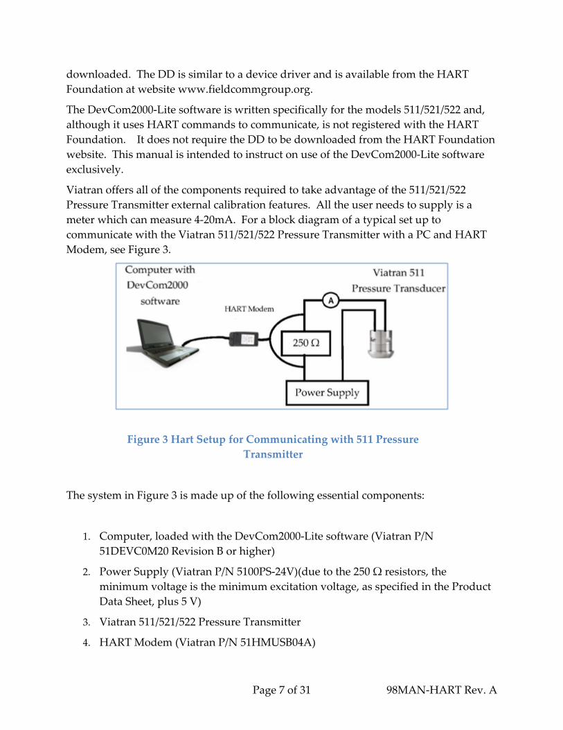
Viatran offers all of the components required to take advantage of the 511/521/522
Pressure Transmitter external calibration features. All the user needs to supply is a
meter which can measure 4‐20mA. For a block diagram of a typical set up to
communicate with the Viatran 511/521/522 Pressure Transmitter with a PC and HART
Modem, see Figure 3.
The system in Figure 3 is made up of the following essential components:
1. Computer, loaded with the DevCom2000‐Lite software (Viatran P/N
51DEVC0M20 Revision B or higher)
2. Power Supply (Viatran P/N 5100PS‐24V)(due to the 250 Ω resistors, the
minimum voltage is the minimum excitation voltage, as specified in the Product
Data Sheet, plus 5 V)
3. Viatran 511/521/522 Pressure Transmitter
4. HART Modem (Viatran P/N 51HMUSB04A)
Figure 3 Hart Setup for Communicating with 511 Pressure
Transmitter

Page 8 of 31 98MAN‐HART Rev. A
5. 250 Ω Resistor (Viatran P/N 51HMF‐L00P)
6. Multimeter which can measure 4 to 20 mA
HART® is a registered trademark of the HART® Communications Foundation.
NavigatingtheSoftware
StartingtheSoftwarefortheFirstTime
The DevCom2000‐Lite icon was installed on your Desktop during the installation
process. (See below) Double click the icon to launch the software.
The first time you start the DevCom2000‐Lite software after installation you will be
prompted to create a password. The prompt box will look as shown in Figure 4. The
password must be between 4 and 8 characters and may contain any combination of
upper and/or lower case letters, numbers and/or symbols. It is recommended that you
record the password in a safe place.
Figure 4 Create Password
Enter th
confirm
cancel th
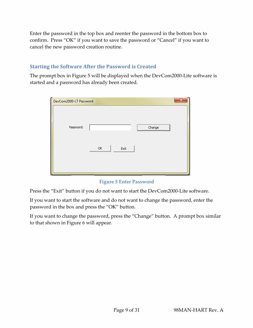
Starting
The prom
started a
Press the
If you w
passwor
If you w
to that s
he password
. Press “OK
he new pas
gtheSoftw
mpt box in
and a passw
e “Exit” bu
want to start
rd in the bo
want to chan
hown in Fi
d in the top
K” if you w
sword crea
wareAfter
Figure 5 w
word has al
utton if you
t the softwa
ox and pres
nge the pas
gure 6 will
Pa
box and re
want to save
ation routin
rthePassw
will be displ
lready been
Figure 5
do not wan
are and do n
s the “OK”
sword, pre
appear.
age 9 of 31
eenter the p
e the passw
ne.
wordisCr
layed when
n created.
Enter Pass
nt to start th
not want to
button.
ss the “Cha
password in
word or “Can
reated
n the DevCo
word
he DevCom
o change th
ange” butto
98MAN
n the bottom
ncel” if you
om2000‐Lit
m2000‐Lite s
he password
on. A prom
N‐HART Re
m box to
u want to
te software
software.
d, enter the
mpt box sim
ev. A
is
milar

Page 10 of 31 98MAN‐HART Rev. A
Figure 6 Create Password
Enter the current password in the top box. Enter the new password in the middle box
and reenter the new password in the bottom box to confirm. Press “OK” if you want to
save the new password and “Cancel” if you want to cancel the new password creation
routine.
You will be taken back to the screen shown in Figure 4. Proceed as described above for
this display.
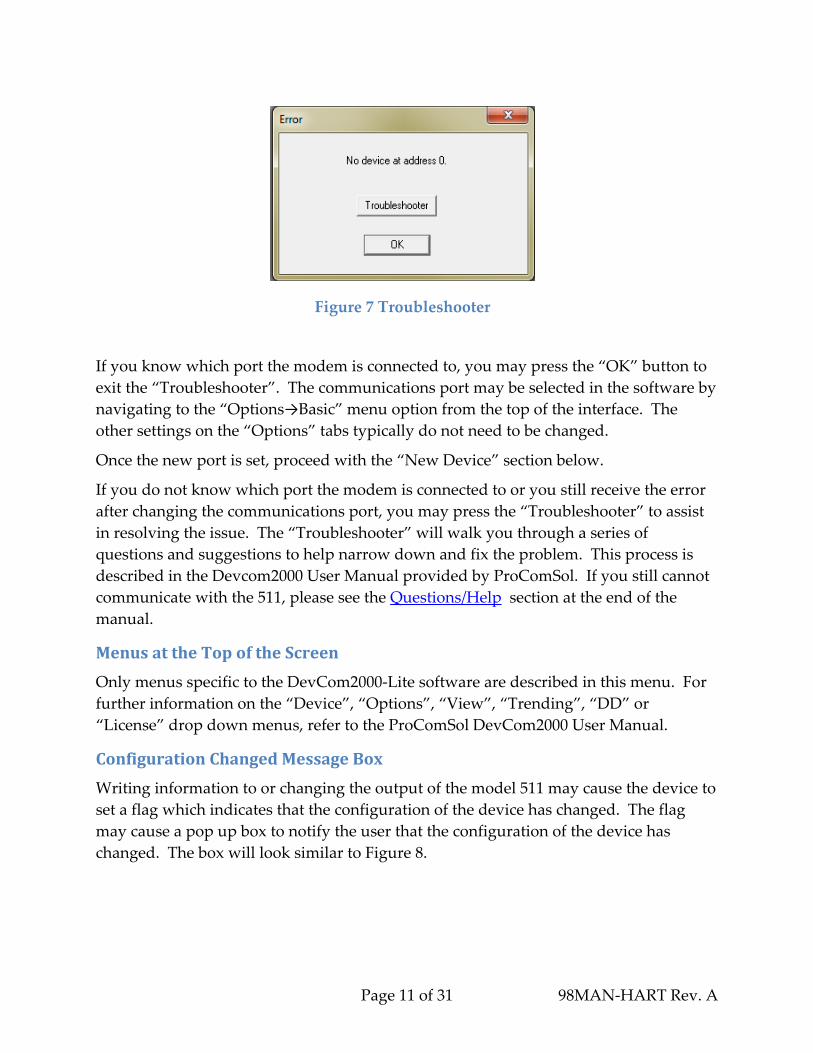
ErroronSoftwareStart
The error box shown in Figure 7 may appear on start of the DevCom2000‐Lite software
indicating that the software is not able to detect the device. This may indicate that the
computer port used for communicating with the device is not set properly. By default,
the DevCom2000 Lite software is set up for COM99.
Page 11 of 31 98MAN‐HART Rev. A
If you know which port the modem is connected to, you may press the “OK” button to
exit the “Troubleshooter”. The communications port may be selected in the software by
navigating to the “Options→Basic” menu option from the top of the interface. The
other settings on the “Options” tabs typically do not need to be changed.
Once the new port is set, proceed with the “New Device” section below.
If you do not know which port the modem is connected to or you still receive the error
after changing the communications port, you may press the “Troubleshooter” to assist
in resolving the issue. The “Troubleshooter” will walk you through a series of
questions and suggestions to help narrow down and fix the problem. This process is
described in the Devcom2000 User Manual provided by ProComSol. If you still cannot
communicate with the 511, please see the Questions/Help section at the end of the
manual.
MenusattheTopoftheScreen
Only menus specific to the DevCom2000‐Lite software are described in this menu. For
further information on the “Device”, “Options”, “View”, “Trending”, “DD” or
“License” drop down menus, refer to the ProComSol DevCom2000 User Manual.
ConfigurationChangedMessageBox
Writing information to or changing the output of the model 511 may cause the device to
set a flag which indicates that the configuration of the device has changed. The flag
may cause a pop up box to notify the user that the configuration of the device has
changed. The box will look similar to Figure 8.
Figure 7 Troubleshooter

Page 12 of 31 98MAN‐HART Rev. A
The device will continue to send back the configuration changed flag until the flag is
cleared. Clearing the configuration changed flag is described in the Device Status
section.
Pressing “OK” will acknowledge this occurrence of the flag. The box will be displayed
again on the next communication with device unless the flag is cleared.
Pressing “IGNORE” will ignore the flag sent back for a number of messages. The
number of messages is set in the box and defaults to 500
Pressing “ALL” will ignore the flag indefinitely.
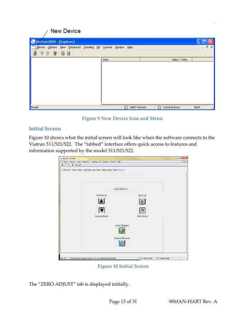
NewDevice
If you need to change the device or if you attached the device after bringing up the
software, you can direct the software to recognize the device by clicking the “New
Device” Icon indicated at the right or from the top menu select Device → New Device.
See Figure 9. The software will automatically load your new device and take you to the
initial screen.
Figure 8 Configuration Changed Pop‐up
Page 13 of 31 98MAN‐HART Rev. A
InitialScreen
Figure 10 shows what the initial screen will look like when the software connects to the
Viatran 511/521/522. The “tabbed” interface offers quick access to features and
information supported by the model 511/521/522.
Figure 10 Initial Screen
The “ZERO ADJUST” tab is displayed initially.
Figure 9 New Device Icon and Menu

Page 14 of 31 98MAN‐HART Rev. A
TrimProcedure
The Trim function provides the ability to make adjustments to the zero and span
outputs. Span trim is not available from the tabbed interface. This will be discussed in
the Span Trim section.
ZeroAdjust
A zero adjust should be performed before the span is adjusted. Follow the steps below
to trim the zero output:
1. Vent any pressure applied to the sensor.
2. To adjust the zero reading click on either the coarse or fine zero up or down
menu button to increase or decrease the milliamp output of the unit. Continue
until your device is as close as possible to the desired output.
3. The zero setting must be stored in the 511/521/522 by clicking the “Save
Changes” button. The “Save Zero Changes” option box will prompt you to
confirm whether or not you wish to save the zero setting to the device. (see
Figure 11) If the settings are not saved when the unit is powered down, it will go
back to the last saved setting when it is powered back up.
Figure 11 Save Zero Changes Option Box
NOTE: The “Factory Restore” button is provided to return the device to the factory
trimmed zero and span settings. (see section “Factory Restore”)
SpanAdjust
The calibration circuit of the Model 511/521/522 may be used to determine if a
calibration of the unit is required. Please reference the 511/521/522 manual to activate
the calibration feature. The milliamp output of the unit should be close to the current
that is indicated on the Performance Certificate for the 511/521/522. If it is not, this
indicates the product should be calibrated. Performance Certifications are available

Page 15 of 31 98MAN‐HART Rev. A
online via Viatranʹs password protected customer portal. Contact customer service for
information on this capability or go to www.viatran.com and register for portal access.
Tip: You may want to record the calibration output and pressure from the
Performance Certificate into one of the user fields. These fields are described
in the Device Section.
If the current measurement is not within tolerance it indicates, the unit is out of
calibration and must be connected to a calibrated pressure source to adjust the span.
Do not adjust the Span without a calibrated pressure source.
Span trim is accessed from the “Enhanced” menu item at the top of the screen. (See
Figure 12) The span trim interface will appear as shown in Figure 13.
Figure 12 Menu Tree for Span Trim Interface
Page 16 of 31 98MAN‐HART Rev. A
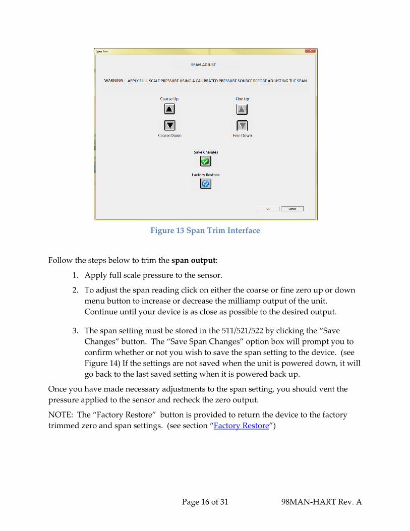
Figure 13 Span Trim Interface
Follow the steps below to trim the span output:
1. Apply full scale pressure to the sensor.
2. To adjust the span reading click on either the coarse or fine zero up or down
menu button to increase or decrease the milliamp output of the unit.
Continue until your device is as close as possible to the desired output.
3. The span setting must be stored in the 511/521/522 by clicking the “Save
Changes” button. The “Save Span Changes” option box will prompt you to
confirm whether or not you wish to save the span setting to the device. (see
Figure 14) If the settings are not saved when the unit is powered down, it will
go back to the last saved setting when it is powered back up.
Once you have made necessary adjustments to the span setting, you should vent the
pressure applied to the sensor and recheck the zero output.
NOTE: The “Factory Restore” button is provided to return the device to the factory
trimmed zero and span settings. (see section “Factory Restore”)

Page 17 of 31 98MAN‐HART Rev. A
Figure 14 Save Span Changes Dialogue Box
After performing the calibration, it is recommended that you make note of the
calibration date and settings in the User fields of the 511/521/522.
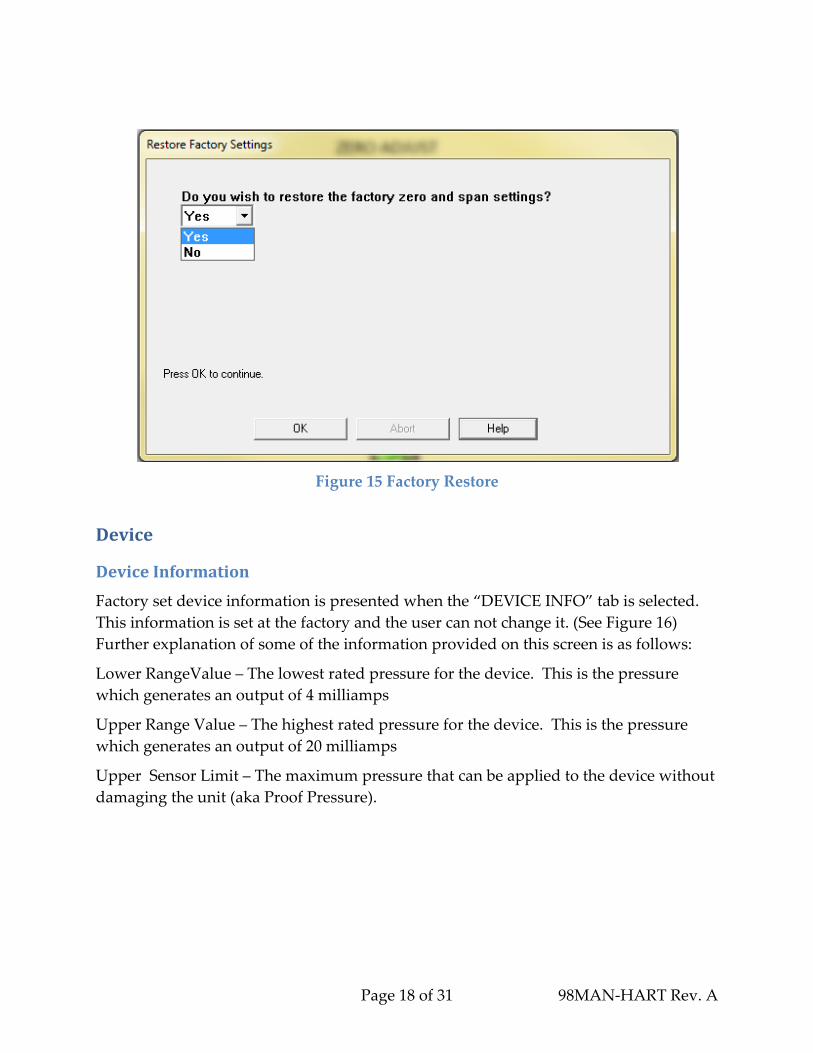
FactoryRestore
The factory set zero and span may be restored by clicking the “Factory Restore”. This
button is available on both the “ZERO ADJUST” tab and the “Span Trim” interface.
You will be asked to confirm that you wish to perform this operation. (Figure 15) If it
has been more than 12 months since the unit has been calibrated by Viatran or an
authorized Viatran Repair Center, you may not want to restore factory settings as they
may not accurately reflect the pressure being applied to the sensor. These calibration
fields are only updated when the product is calibrated by Viatran or an authorized
Viatran Repair Center. If a unit is returned to Viatran for repair or calibration and a
trim is performed on the unit, the unit will reflect the factory settings from that last trim
event from the factory.
Page 18 of 31 98MAN‐HART Rev. A
Figure 15 Factory Restore
Device
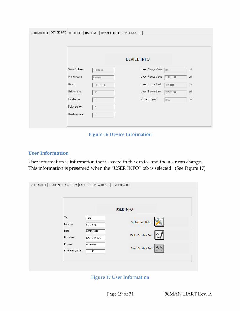
DeviceInformation
Factory set device information is presented when the “DEVICE INFO” tab is selected.
This information is set at the factory and the user can not change it. (See Figure 16)
Further explanation of some of the information provided on this screen is as follows:
Lower RangeValue – The lowest rated pressure for the device. This is the pressure
which generates an output of 4 milliamps
Upper Range Value – The highest rated pressure for the device. This is the pressure
which generates an output of 20 milliamps
Upper Sensor Limit – The maximum pressure that can be applied to the device without
damaging the unit (aka Proof Pressure).
Page 19 of 31 98MAN‐HART Rev. A
Figure 16 Device Information
UserInformation
User information is information that is saved in the device and the user can change.
This information is presented when the “USER INFO” tab is selected. (See Figure 17)
Figure 17 User Information

Page 20 of 31 98MAN‐HART Rev. A
The field sizes are as follows:
Figure 18 User Information Field Sizes
To change the information, click in the box that you want to edit, or double click to
select the whole field. Make the edits you want and then hit enter or click in another
block. The field that has been changed will turn yellow as shown in Figure 19. The
yellow indicates which fields contain information that is different than what is in the
unit. By clicking the Send to Device icon in the top menu (shown below) the
information will be transferred to the device.
You can cancel your edits by clicking the cancel edits icon in the top menu (also shown
below).
Figure 19 User Information with Edit

Clicking
Figure 2
Select a
appear.
several s
g on the “Ca
20. These m
date to edit
Edit the ca
seconds for
alibration D
may be use
Figu
t and press
alibration d
r the inform
Fi
Pag
Dates” butto
ed to record
ure 20 Calib
the “OK” b
date in the b
mation to be
igure 21 Ed
ge 21 of 31
on will pop
d up to five
bration Dat
button. A m
box and pre
e recorded i
dit Calibrat
p up the sel
calibration
te Selection
message bo
ess “OK” to
in the devic
tion Date
98MAN
lection box
n dates.
n
ox similar to
o continue.
ce.
N‐HART Re
shown in
o Figure 21
It may take
ev. A
will
e

Page 22 of 31 98MAN‐HART Rev. A
The scratch pad is a ninety‐six character storage area inside the device which may be
used to store and read back information. To write data to the scratch pad area, click the
“Write Scratch Pad” button. A message box similar to Figure 22 will pop up. Enter the
information you wish to store in the box. The text will scroll if you exceed the length of
the box. Up to ninety‐six characters may be entered. Click the “OK” button to send the
information to the device. This may take several seconds.
Figure 22 Write User Scratch Pad
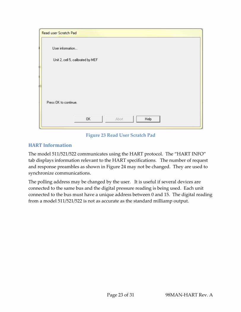
To read data from the scratch pad area, click the “Read Scratch Pad” button. A
dialogue box similar to Figure 23 will pop up. This may take several seconds.
Page 23 of 31 98MAN‐HART Rev. A
Figure 23 Read User Scratch Pad
HARTInformation
The model 511/521/522 communicates using the HART protocol. The “HART INFO”
tab displays information relevant to the HART specifications. The number of request
and response preambles as shown in Figure 24 may not be changed. They are used to
synchronize communications.
The polling address may be changed by the user. It is useful if several devices are
connected to the same bus and the digital pressure reading is being used. Each unit
connected to the bus must have a unique address between 0 and 15. The digital reading
from a model 511/521/522 is not as accurate as the standard milliamp output.

Page 24 of 31 98MAN‐HART Rev. A
Figure 24 HART Information
DynamicInformation
The “DYNAMIC INFO” tab displays information which is changing. (See Figure 25)
The box at the top displays and updates the pressure as it is read back from the device.
This is a digital pressure represented by the milliamp output generated by the device.
Figure 25 Dynamic Information
Page 25 of 31 98MAN‐HART Rev. A
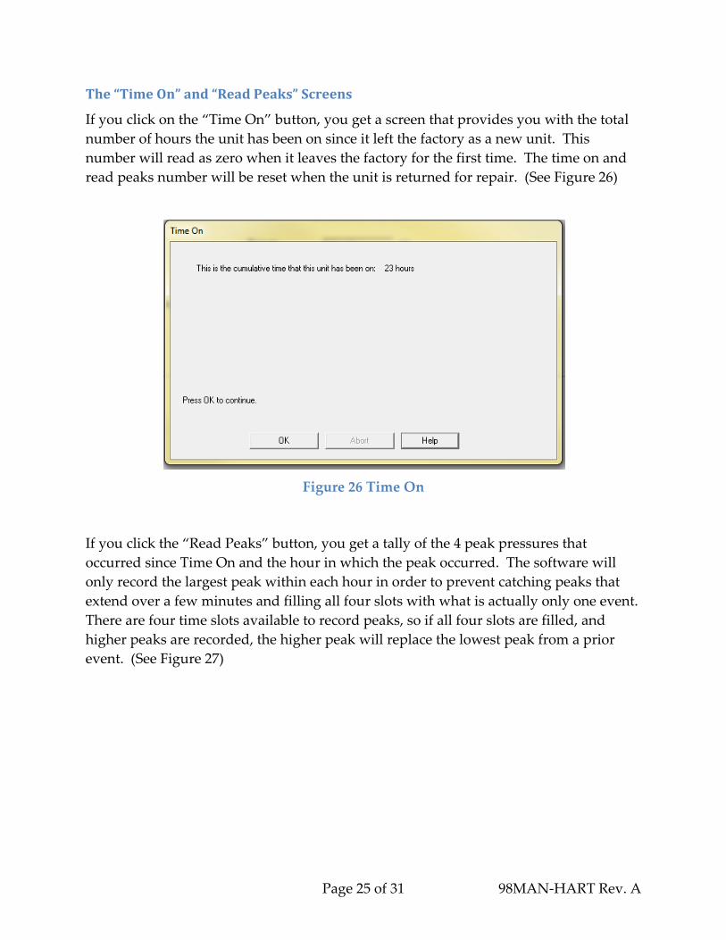
The“TimeOn”and“ReadPeaks”Screens
If you click on the “Time On” button, you get a screen that provides you with the total
number of hours the unit has been on since it left the factory as a new unit. This
number will read as zero when it leaves the factory for the first time. The time on and
read peaks number will be reset when the unit is returned for repair. (See Figure 26)
Figure 26 Time On
If you click the “Read Peaks” button, you get a tally of the 4 peak pressures that
occurred since Time On and the hour in which the peak occurred. The software will
only record the largest peak within each hour in order to prevent catching peaks that
extend over a few minutes and filling all four slots with what is actually only one event.
There are four time slots available to record peaks, so if all four slots are filled, and
higher peaks are recorded, the higher peak will replace the lowest peak from a prior
event. (See Figure 27)

Page 26 of 31 98MAN‐HART Rev. A
Figure 27 Read Peaks and Time On Occurrence
There is no feature in the 511/521/522 device that provides the date and time of the
peaks. If you want to determine when peaks actually occurred, you can create a
manual log in one of the user fields whereby you type in the dates and times that the
511/521/522 device has been turned on and off and cross reference those dates and times
to the values in the Time on column of the “Read Peaks” screen. More information on
user fields is provided in the “Device” section.
The maximum peak reading that can be detected is approximately 140% of the rated
pressure or pressure range of the unit.
DeviceStatus
The status of the model 511/521/522 is displayed on the “DEVICE STATUS” tab. (See
Figure 28) The device is capable of communicating various warnings, information or
errors and these are indicated on this screen. A graphical LED is displayed next to each
description. A red LED indicates that this status message has been sent back from the
device and the warning or error has been detected. (See Figure 31) A green LED means
this warning or error has not been sent back from the device and has not been detected.

Most of
indicato
The “De
device.
the zero
informa
will auto
the indicat
ors are autom
evice Config
The “Devic
or span set
tion on the
omatically
ors will cle
matically cl
guration Ch
ce Configur
ttings have
“USER IN
clear the fla
Pag
Figure 2
Figure 29 R
ar when th
leared by th
hanged” sta
ration Chan
e been chan
FO” tab is c
ag if the zer
ge 27 of 31
28 Device S
Red LED W
he condition
he software
atus indicat
nged” statu
nged and sa
changed an
ro or span s
tatus
Warning
n is remove
e.
tes a chang
us is inform
ved to the d
nd sent to th
settings are
98MAN
d. Some of
ge has been
mational. It
device or w
he device.
e changed.
N‐HART Re
f these
made to th
occurs whe
when
The softwa
The flag w
ev. A
he
en
are
ill

Page 28 of 31 98MAN‐HART Rev. A
not be cleared automatically if any other information is saved to the device. If the flag is
not cleared, it will be sent with every message from the unit. The “Device
Configuration Changed” LED will be red. If this happens, the “Clear Device
Configuration Changed Flag” button can be pressed to clear the flag. The “Device
Configuration Changed” LED will turn green when the flag is cleared.
A red “Additional Device Status Available” LED indicates more information is
available. The additional information is presented in the box labeled “Additional
Device Specific Status”. The “Clear Additional Device Status Available Flag” button
may be pressed to clear the “Additional Device Status Available” warning.
AdditionalDeviceInformation
Additional device information may be viewed by navigating to the “Enhanced →
About” menu options at the top of the screen. The “Device Info” and “Manufacturer
Calibrations” submenus may become available.
The “Manufacturer Calibrations” option presents dates of up to four factory
calibrations.
The “Device Info” menu will look similar to Figure 30.
Figure 30 Read Additional Device Information

Questio
If you ha
refer to t
provide
ProCProcess
13001 A
Suite 220
Lakewo
USA
Phone:
Toll Free
Fax:
E‐mail:
If you ha
Transmi
199 Fire
Tonawa
Internat
Toll Free
Fax: 1‐71
Email: s
ons/Help
ave questio
the DevCom
d below:
ComSCommuni
thens Ave
0
od, OH 44
216.221
e: 877.221
216.221
sales@p
ave questio
itter device
Tower Dri
anda, NY 14
ional: 1‐716
e: 1‐800‐688
16‐693‐9162
olutions@v
p
ons concern
m2000 User
Sol, Lications So
107
.1550
1.1551
.1554
rocomsol.c
ons concern
e, contact Vi
ve
4150
6‐629‐3800
8‐0030
2
viatran.com
Pag
ning the ins
r manual or
Ltd
olutions
om
ning the Tri
iatran using
ge 29 of 31
tallation of
r contact Pr
m function
g the inform
f ProComSo
roComSol u
n or the 511/
mation prov
98MAN
ol software
using the in
/521/522 Pr
vided below
N‐HART Re
or its featu
nformation
essure
w:
ev. A
ures,

Page 30 of 31 98MAN‐HART Rev. A
APPENDIXA:HardwareSet‐upusingthePowerXpressmodule(Optional)
Viatran offers an optional integrated solution called “PowerXpress” (Viatran P/N 51PS‐
EXPRS) which combines some of the components into a kit or module to speed up the
setup process. Please note, the PowerXpress module does not include the HART
Modem. If using the PowerXpress module, the following essential components are
required in order to communicate with the 511/521/522 Pressure Transmitter:
1. PowerXpress
a. Power supply, which can operate from a PC USB port or 120 Vac
b. Built in HART Network load resistor
c. Connections for multimeter probes
d. Banana plugs for the HART modem
e. 110Vac adapter
2. HM‐USB‐ISO‐BP, USB HART Modem, Isolated, Banana Plug Option
3. Multimeter, which can measure 4 to 20 mA
Follow these steps in order to communicate with the 511/521/522 Pressure Transmitter
from your PC (see Figure 31 for a photo of the correct setup)
1. Install the USB Virtual Serial Port Driver onto the computer
2. Plug the HART modem into the computer
3. Plug the PowerXpress module into the computer
4. Plug the HART modem into modem plugs labeled “Modem Handheld” on the
PowerXpress Box.
5. Plug mA meter probes into the PowerXpress module labeled “mAdc” on the
PowerXpress Box observing proper polarity.
6. Attach the power clips of the PowerXpress to the power pins of the 511/521/522.
The pin out information is indicated on the side of the 511/521/522 as well as in
the performance certification included with every 511/521/522. If you are unable
to locate the performance certificate, you can download a copy from our website.

Page 31 of 31 98MAN‐HART Rev. A
After you set up your hardware, run the HM Test Software by clicking the HM Test
icon on your pc desktop (see example of icon below), which was installed with the
HART modem software. Do this to determine which port is connected to the HART
modem.
The HM Test Software will guide you through a process of trial and error in order to
identify the correct port to select for proper operation of the software. Once you have
identified the correct port, change the port number in the DevCom2000‐Lite software to
the correct port by clicking the Options from the top menu, then Basic, and then select
the appropriate com port number. (See Figure 32)
Figure 32 Basic Menu
Figure 31 Example of a set up using the
PowerXpress