eclass.krs.co.kr · CHAPTER 2 PERIODICAL AND OTHER SURVEYS ... be indicated by the appropriate...
481
Rules Guidance
Transcript of eclass.krs.co.kr · CHAPTER 2 PERIODICAL AND OTHER SURVEYS ... be indicated by the appropriate...

Rules
Guidance
2017Rules for the Classification of Steel Ships
Part 1 Classification and Surveys
2017Guidance Relating to the Rules for the Classification of Steel Ships
Part 1 Classification and Surveys

Rule
s
2017
Rules for the Classification of Steel Ships
Part 1
Classification and Surveys
RA-01-E KR

- i -
APPLICATION OF PART 1 "CLASSIFICATION AND SURVEYS"
1. Unless expressly specified otherwise, the requirements in the Rules apply to ships for which the
application for Classification Survey is submitted to the Society on or after 1 July 2017.
2. The amendments to the Rules for 2016 edition and their effective date are as follows;
Effective Date 1 January 2017
CHAPTER 1 CLASSIFICATION
Section 7 Cooperation Duties of Owners
- 703. has been amended.
CHAPTER 2 PERIODICAL AND OTHER SURVEYS
Section 7 Surveys of Propeller Shaft and Stern Tube Shaft, Etc.
- 701. 3 (19) has been newly added.
- 702. 3 (2) (A) (b) and (c) have been amended.
- 702. 4 (2) (A) (b) and (c) have been amended.
- 702. 5 has been amended.
- 703. 2 (1) (E) (a) and (2) (D) (a) have been amended.
CHAPTER 3 HULL SURVEYS OF SHIPS SUBJECT TO THE ENHANCED
SURVEY PROGRAMME
Section 1 General
- 101. 2, 2 (1) and 2 (3) have been amended.

- ii -
Effective Date : 1 July 2017
CHAPTER 2 PERIODICAL AND OTHER SURVEYS
Section 1 General
- 101. 26 has been newly added.
Section 2 Annual Survey
- 202. 1 (30) has been moved from Guidance.
Section 4 Special Survey (Hull, Equipment and Fire-extinguishing Appliances)
- 403. 1. (7) Table 1.2.3 has been amended.
Section 8 Boiler Survey
- 802. 1 (1) has been amended.
Section 14 Hull Surveys for General Dry Cargo Ships
- 1404. 5 has been amended.
Section 18 Special Requirements for Ships Subject to Korean Ship Safety Act or
Fishing Vessels Act
- 1801. 2 has been amended.
CHAPTER 3 HULL SURVEYS OF SHIPS SUBJECT TO THE ENHANCED
SURVEY PROGRAMME
Section 2 Bulk Carriers
- 203. 4 (1) (a) has been amended.
Section 6 Double Skin Bulk Carriers
- 604. 1. (5) has been amended.
Effective Date : 1 July 2017 (based on the contract date for ship construction or an
application date for a periodical or occasional machinery survey after the
retrofit of harmonic filters)
CHAPTER 2 PERIODICAL AND OTHER SURVEYS
Section 2 Annual Survey
- 203. 27 has been newly added.

- iii -
CONTENTS
CHAPTER 1 CLASSIFICATION ······················································································· 1
Section 1 General ············································································································· 1
Section 2 Character of Classification ·············································································· 2
Section 3 Classification Survey during Construction ····················································· 4
Section 4 Classification Survey after Construction ························································ 6
Section 5 Certificates and Reports ·················································································· 7
Section 6 Application for Survey ···················································································· 8
Section 7 Cooperation Duties of Owners ······································································· 9
Section 8 Competence and Duties of Surveyors ·························································· 10
Section 9 Suspension/Withdrawal of Class and Reclassification ································· 12
Section 10 Fees ················································································································· 14
Section 11 Appeal on Disagreement ··············································································· 14
Section 12 Related Regulations and Surveys ·································································· 14
Section 13 Classification of Other Installations or Equipment ······································ 15
Section 14 External Audit ································································································ 15
Section 15 Miscellaneous ································································································· 16
CHAPTER 2 PERIODICAL AND OTHER SURVEYS ··············································· 17
Section 1 General ··········································································································· 17
Section 2 Annual Survey ······························································································· 25
Section 3 Intermediate Survey ······················································································· 36
Section 4 Special Survey(Hull, Equipment and Fire-extinguishing Appliances) ········· 41
Section 5-1 Special Survey(Machinery, Electrical Installations and Additional Installations) ··· 51
Section 5-2 Special Survey(Additional Requirements to Ship Types) ··························· 54
Section 6 Docking Survey ····························································································· 57
Section 7 Surveys of Propeller Shaft and Stern Tube Shaft, Etc. ····························· 63
Section 8 Boiler Survey ································································································· 71
Section 9 Continuous Survey of Machinery ································································· 72
Section 10 Occasional Survey ·························································································· 73
Section 11 Alteration Survey ··························································································· 73
Section 12 Survey of Ships Carrying Dangerous Goods and Other Special Cargoes ··· 74
Section 13 Additional Installations Survey ····································································· 74
Section 14 Hull Surveys for General Dry Cargo Ships ················································ 75
Section 15 Hull Surveys for Liquefied Gas Carriers ····················································· 84
Section 16 Survey Requirements for Shell and Inner Doors, Etc. of RoRo Ships ···· 91
Section 17 Additional Requirements ················································································ 95
Section 18 Special Requirements for Ships Subject to Korean Ship Safety Act
or Fishing Vessels Act ················································································· 96

- iv -
CHAPTER 3 HULL SURVEYS OF SHIPS SUBJECT TO THE ENHANCED
SURVEY PROGRAMME ········································································· 99
Section 1 General ··········································································································· 99
Section 2 Bulk Carriers ································································································ 110
Section 3 Oil Tankers ·································································································· 123
Section 4 Chemical Tankers ························································································· 130
Section 5 Double Hull Oil Tankers ············································································ 138
Section 6 Double Skin Bulk Carriers ········································································· 145

Pt 1 Classification and Surveys
Ch 1 Classification Pt 1, Ch 1
Rules for the Classification of Steel Ships 2017 1
CHAPTER 1 CLASSIFICATION
Section 1 General 【See Guidance】
101. Classification
1. Steel ships built and surveyed in accordance with the Rules of the Society(hereafter referred to as "the Rules") or with the alternatives equivalent to the Rules will be assigned a class designation by the Society and registered in the Register of Ships.
2. All ships classed with the Society are, for continuation of the classification, to be subjected to the periodical and other surveys, and are to be maintained in good condition in accordance with the re-quirements of the Rules.
3. When a ship classed with the Society makes an alteration or modification of such an extent as to influence to the ship's original performances, the plans have to be submitted for the Society's ap-proval before the work is commenced and the alteration work has to be supervised by the Surveyor.
102. Standard application of the Rules
1. The Rules are framed on the understanding that ships will be properly loaded and handled and not, unless stated in the class notation, provide special distributions and concentrations of loading.
2. The plans of ships designed for specific condition of loading or particular features in respect of the hull, machinery or equipment are also to be submitted for approval.
103. Exclusion from the Rules
The Society cannot assume responsibility for trim, hull vibration or other technical characteristics not covered by the Rules. However, the Society may advise on such matters upon application by an Owner.
104. Equivalence 【See Guidance】
The Society may consider the acceptance of alternatives to the Rules, provided that they are deemed to be equivalent to the Rules to the satisfaction to the Society.
105. Novel features 【See Guidance】
The Society may consider the classification of ships based on or applying novel design principles or features, to which the Rules are not directly applicable, on the basis of experiments, calculations or other supporting information provided to the Society.

Pt 1 Classification and Surveys
Ch 1 Classification Pt 1, Ch 1
2 Rules for the Classification of Steel Ships 2017
Section 2 Character of Classification
201. Class notations 【See Guidance】
The class notations assigned to the ships classed with the Society are to be in accordance with the followings:
(1) Construction symbolsThe construction symbols assigned to the ships according to the distinction of Classification Survey are to be in accordance with the followings:
✠ ; For ships built under the supervision of the Society.No symbol ; For ships considered to be fit as the result of surveys by the Surveyor after
construction with the exception of the above mentioned construction symbols.
(2) Service restriction notations of hullThe following service restriction notations will be given for ships with hull construction and strength found to be in compliance with the Rules:
KRS 1 ; For ships unrestricted in service area.KRS 0 ; For ships restricted in service area.
(3) Service restriction notations of machineryThe following service restriction notations will be given for ships with machinery and electrical installations found to be in compliance with the Rules:
KRM 1 ; For ships unrestricted in service area.KRM 0 ; For ships restricted in service area.
(4) Service restriction notations of equipmentThe following service restriction notations will be given for ships with equipment found to be in compliance with the Rules:
No symbol ; For ships unrestricted in service area.C ; For ships approved with the condition of coastal service.S ; For ships approved with the condition of smooth water service.

Pt 1 Classification and Surveys
Ch 1 Classification Pt 1, Ch 1
Rules for the Classification of Steel Ships 2017 3
(5) Additional installations notationsShips designed for the application of additional installations on hull items will be distinguished after the character of hull by the class notation such as "LI", "CHA", "HMS" or "HMS1", etc. and on machinery items will be distinguished after the character of machinery by the class no-tation such as "CMA", "UMA", "DPS", "NBS", "IGS", "COW", "STCM" or "RMC", etc.
(6) Ship type notationsShips designed in compliance with particular Rules intended to apply to that type of ship will be indicated by the appropriate designations such as Oil Tanker 'ESP'(FBC), Bulk Carrier 'ESP', Cargo Ship, Passenger Ship, Tug Boat, Barge, etc. affixed to the character of hull.
(7) Special feature notationsWhen considered necessary by the Society, the special feature notations may be appended to the character of the ship type notations. These special feature notations could consist of the hull structure and the cargo tank type fitted for the kind and nature of cargoes, ice strengthening, in-water survey, cargo loading condition, design temperature, design pressure, the apparent spe-cific gravity of cargoes, corrosion control, direct strength assessment, direct fatigue assessment, hull construction monitoring, and/or longitudinal strength of hull girder in flooded condition for bulk carriers, etc. Also, the restriction of navigation area and condition may be remarked additionally.
202. Class notations of large yachts
The class notations of large yachts classed with the Society are to be in accordance with the re-quirements specified in Pt 1, Ch 1, 103. of the Guidance for Large Yachts irrespective of the requirements in 201.
203. Class notations of recreational crafts
The class notations of recreational crafts classed with the Society are to be in accordance with the requirements specified in Ch 1, 103. of the Guidance for Recreational Crafts irrespective of the requirements in 201.

Pt 1 Classification and Surveys
Ch 1 Classification Pt 1, Ch 1
4 Rules for the Classification of Steel Ships 2017
Section 3 Classification Survey during Construction
301. Classification Survey during Construction
For a ship requiring Classification Survey during Construction, the construction, materials, scantlings and workmanship of the hull, equipment and machinery are to be examined in detail in order to ascertain that they meet the appropriate requirements of the Rules. 【See Guidance】
302. Approval of plans
For a ship requiring Classification Survey during Construction, the plans and documents showing the details of the construction, materials, scantlings and particulars of the hull, equipment and ma-chinery are to be submitted in triplicate and approved before the work is commenced. The same applies also to the cases of any subsequent modifications to the approved drawings or documents. 【See Guidance】
303. Materials and equipment
All materials used for a ship requiring Classification Survey during Construction are to be manufac-tured under approved method or under alternative process considered equivalent to the approved method and are to be adequate to the relevant requirements of the Rules. The Society may request the relevant documents such as certificate of materials or equipment, etc. for the confirmation of the materials or equipment which are used.
304. Machinery installation
Main engines, shafting arrangement, boilers, pressure vessels, electrical equipment, essential auxiliary machinery, and piping arrangements to be installed on a ship intended for classification are to be surveyed during construction. Shop trials are to be carried out on completion under a same con-dition as installed on-board ship or a similar condition as far as practicable. Various tests on any special part amongst the automatic or remote control systems and measuring devices considered necessary by the Society may be requested at the manufacturing sites. 【See Guidance】
305. Workmanship
For Classification Survey of a ship, the materials, workmanship and arrangements are to be sur-veyed under the supervision of the Surveyor from the commencement of the work until the com-pletion of the ship. When the machinery is constructed under Classification Survey, this survey is to be related to the period from the commencement of the work until the final test under working conditions. Any item found not to be in accordance with the Rules or the approved plans, or any material, workmanship or arrangement found to be unsatisfactory are to be rectified.
306. Tests
In the Classification Survey during Construction, hydrostatic, watertight and performance tests are to be carried out in accordance with the relevant part of the Rules. Also the control systems and measuring device after installation are to receive the necessary tests, as deemed necessary by the Society. 【See Guidance】
307. Stability experiments 【See Guidance】
1. In the Classification Survey during Construction for passenger ships and ships of 24 m and above in length other than passenger ships, stability experiments are to be carried out upon completion of the ship. A final stability information booklet adequate for the service intended and prepared on the basis of the stability particulars determined by the results of stability experiments, is to be ap-proved by the Society and supplied to the master. However, a preliminary stability information booklet approved by the Society in lieu of a final stability information booklet may be provided on-board for a specific period.

Pt 1 Classification and Surveys
Ch 1 Classification Pt 1, Ch 1
Rules for the Classification of Steel Ships 2017 5
2. The stability experiments in above Par 1 are to demonstrate that their intact stability is adequate for the service intended. Adequate intact stability means compliance with standards laid down by the relevant Administration or those of the Society taking into account the ship's size and type. The level of intact stability for ships with a length of 24 m and above in any case should not be less than that provided by Part A of IMO Res.MSC.267(85)(Adoption of the international code on intact stability, 2008(2008 IS Code)) as applicable to the type of ship being considered. Where oth-er criteria are accepted by the Administration concerned, these criteria may be used for the purpose of classification. Evidence of approval by the Administration concerned may be accepted for the purpose of classification.
3. Where an loading instrument having a stability computation capability as supplemental use of sta-bility information booklet specified in Par 1 is provided, the test report of representative opera-tional conditions is to be submitted to the Society, and the loading instrument shall cover all stabil-ity requirements applicable to the ship such as intact, damage and grain stability, etc. When the stability information include sufficient loading conditions of the ship, some part of the function may be omitted. The instrument is to be confirmed by the Surveyor upon installation in accordance with the test report approved by the Society.
308. Trials
Trials are to be carried out for all equipment, machinery and electrical equipment under working conditions after completion of the ship in order to ascertain their performances. In the sea trials, speed test, astern test, steering test, emergency steering test and turning test are to be carried out. In addition, the operating conditions of machinery and other behaviors of the ship during the trial are to be examined.
309. Date of contract for construction
1. The date of contract for construction of a vessel is the date on which the contract to build the vessel is signed between the prospective Owner and the shipbuilder. This date and the construction numbers(i.e. hull numbers) of all the vessels included in the contract are to be declared to the Society by the party applying for the assignment of class to a newbuilding.
2. The date of contract for construction of a series of vessels, including specified optional vessels for which the option is ultimately exercised, is the date on which the contract to build the series is signed between the prospective Owner and the shipbuilder.
3. In application to Par 2, vessels built under a single contract for construction are considered a ser-ies of vessels if they are built to the same approved plans for classification purposes. However, vessels within a series may have design alterations from the original design provided;(1) Such alterations do not affect matters related to classification, or(2) If the alterations are subject to classification requirements, these alterations are to comply with
the classification requirements in effect on the date on which the alterations are contracted be-tween the prospective owner and the shipbuilder or, in the absence of the alteration contract, comply with the classification requirements in effect on the date on which the alterations are submitted to the Society for approval.
The optional vessels will be considered part of the same series of vessels if the option is exercised not later than 1 year after the contract to build the series was signed.
4. If a contract for construction is later amended to include additional vessels or additional options, the date of contract for construction for such vessels is the date on which the amendment to the contract, is signed between the prospective Owner and the shipbuilder. The amendment to the con-tract is to be considered as a new contract to which Par 1 to Par 3 above apply.
5. If a contract for construction is amended to change the ship type, the date of contract for con-struction of this modified vessel, or vessels, is the date on which revised contract or new contract is signed between the Owner, or Owners, and the shipbuilder.

Pt 1 Classification and Surveys
Ch 1 Classification Pt 1, Ch 1
6 Rules for the Classification of Steel Ships 2017
Section 4 Classification Survey after Construction
401. Classification Survey after Construction
In the Classification Survey after Construction, the actual scantlings of main parts of the ship are to be measured in addition to such examinations of the construction, materials, workmanship and actual conditions of hull, machinery, outfittings and equipment as required for the Special Survey correspond-ing to the ship's age in order to ascertain that they meet the relevant requirements in the Rules. 【See Guidance】
402. Submission of plans
In the Classification Survey after Construction, plans and documents as may be required for Classification Survey during Construction are to be submitted. If plans cannot be obtained, facilities are to be given for the Surveyor to take the necessary informations from the ship. 【See Guidance】
403. Classification Survey of ships classed by other Societies
When a ship holding class with any Society which is subject to verification of compliance with QSCS(Quality System Certification Scheme) of IACS is intended for classification, plans and docu-ments to be submitted and survey items, etc. are to be in accordance with the Guidance relating to the Rules. 【See Guidance】
404. Tests
In the Classification Survey after Construction, the hydraulic pressure tests, watertight tests, per-formance tests and sea trials are to be carried out in accordance with the requirements of the Rules. However, sea trials may be dispensed with provided that sufficient data on the previous tests are available and neither alteration nor repair affecting the previous data has been made since the previous trials.
405. Stability experiments
In the Classification Survey after Construction for passenger ships and ships of 24 m and above in length other than passenger ships, stability experiments are to be carried out. A final stability in-formation booklet adequate for the service intended and prepared on the basis of the stability par-ticulars determined by the results of stability experiments, is to be approved by the Society and supplied to the master. However, a preliminary stability information booklet approved by the Society in lieu of a final stability information booklet may be provided on-board for a specific period. Stability experiments may be dispensed with provided that sufficient information based on previous stability experiments is available and neither alteration nor repair affecting the stability has been made since the previous experiments. 【See Guidance】

Pt 1 Classification and Surveys
Ch 1 Classification Pt 1, Ch 1
Rules for the Classification of Steel Ships 2017 7
Section 5 Certificates and Reports
501. Certificate of Classification
1. Where ships have undergone the Classification Survey during or after Construction to the sat-isfaction of the Surveyor and approved by the Classification Committee, the ships will be classed and entered in the Register of Ships with the issue of the Certificate of Classification.
2. Where ships have undergone the Special Survey to the satisfaction of the Surveyor, the Certificate of Classification is issued newly.
502. Interim Certificate of Classification
1. Where ships have undergone a Classification Survey during or after Construction to the satisfaction of the Surveyor, the Interim Certificate of Classification will be issued.
2. Where a single direct voyage to repair yard/survey port or demolition yard, etc. is allowed with the Interim Certificate of Classification instead of the Certificate of Classification, an Interim Certificate of Classification will be issued. 【See Guidance】
503. Certificate for construction survey
Where ships not intending to be classed have undergone the survey during construction, or marine engines, boilers, auxiliary machinery and outfittings have undergone the surveys during construction to the satisfaction of the Surveyor, the Certificate for Construction Survey will be issued.
504. Survey reports
On completion of the Classification Survey and the surveys assigned to maintain the classification, the Survey Reports will be issued. Ship's particulars, survey results, the date and description of the next surveys, etc. are to be stated in the Survey Reports. The Survey Reports will be used as no-tice to the Owners.
505. Keeping of the certificates and survey reports
The Certificate of Classification, the Interim Certificate of Classification, Particular Sheets and Survey Reports, etc. are always to be kept on board by the master of the ship and are to be pro-duced when requested by the Surveyor.
506. Mention on certificate
1. Where ships classed with the Society have satisfactorily undergone the periodical survey, or where the period of validity of the Certificate of Classification is extended, or where the anniversary date is amended, the periodical survey or the case will be endorsed on the Appendix of Certificate of Classification or Interim Certificate of Classification.
2. Assigning of date of build
(1) The year, month and date at which the Classification Survey during Construction is completed shall be specified as the "Date of Build". Where there is substantial delay between completion of the Classification Survey during Construction and the ship commencing active service, the date of commissioning may be also specified.
(2) Where the ship is altered, the Date of Build shall be remain assigned to the ship and the al-tered parts are to be complied with Ch 2, Sec 11.

Pt 1 Classification and Surveys
Ch 1 Classification Pt 1, Ch 1
8 Rules for the Classification of Steel Ships 2017
507. Re-issue and return of certificate
1. When the Certificate of Classification, the Interim Certificate of Classification, Particular Sheets, or Survey Reports are lost or impaired, or when the items stated in them require alteration, the appli-cation for re-issue must be made without delay.
2. When a ship holding the Interim Certificate of Classification is furnished with the Certificate of Classification, when the certificate is re-issued except in the case of its loss, or when the classi-fication is cancelled, the old certificate is to be returned to the Society without delay.
508. Certificates of related equipment
The Society may, upon application, survey such equipment relating to ships as prime movers, shaft-ings, boilers, pressure vessels, auxiliary machinery, electrical equipment and other machinery in-stallations and issue certificates where they are to the satisfaction of the Surveyor.
509. Class Maintenance Certificate
The Society will issue, upon request, a Class Maintenance Certificate to the Owner of a ship or the person having obtained his consent.
Section 6 Application for Survey
601. Classification Survey
The application for Classification Survey is to be made by the Builder for a ship during con-struction and by the Owner for a ship after construction. 【See Guidance】
602. Periodical and other surveys
The application for surveys of ship for the continuation of her classification is to be made by the Owner(including Charterer, Representatives of Owner, Representatives of Charterer and Master of the ship, hereafter referred to as "the Owner"). 【See Guidance】
603. Re-issue of certificate
The application for re-issue and return of the Classification Certificate, the Interim Classification Certificate, Particular Sheets and Survey Reports are to be made by the Owner.

Pt 1 Classification and Surveys
Ch 1 Classification Pt 1, Ch 1
Rules for the Classification of Steel Ships 2017 9
Section 7 Cooperation Duties of Owners
701. Report items
When any of the following cases occurs, the Owner is to report to the Society without delay:(1) When the ship is sustained with a sea casualty by which her present class is deemed affected.(2) When the ship is placed in drydock or on a slipway.(3) When the ship is laid up or dismantled.(4) When the Owner is changed.(5) When the ship is withdrawn.(6) When any items which may affect her class are changed.
702. Cooperation of survey
1. All such preparations as required for Classification Survey and surveys necessary for the main-tenance of class are to be made by the applicant of the survey in accordance with the requirements of the Rules. To permit safe and effective survey, such preparations are to include the provision of the work environment and safety measures in the way of suitable lighting, ventilation and access condition.
2. The Owner, master, chief engineer or their representatives are to attend the survey according to the items to be examined and are to give necessary assistances.
3. When a ship is to be surveyed, it is the duty of the Owner to inform the Surveyor of the correct place and items of survey.
4. Where it is intended to use service suppliers for the survey of ship, the service suppliers approved by the Society are used as a general rule, and the approval procedure and items are to be in ac-cordance with the Guidance relating to the Rules. 【See Guidance】
5. The applicant of the survey is to ensure that there is no falsehood in the description on the appli-cation form, the notice and the presented data, etc. to the Society.
703. Cooperation Duties (2017)
Notwithstanding the general duty of confidentiality owed by the Society to its clients as specified in 805., the Society's clients hereby accept that the Society will participate in Early Warning Scheme which requires each Society to provide the involved Societies (the Classification Societies classing a sister or a similar ship to the one involved in the incident) with relevant technical in-formation (but not including any drawings relating to the ship which may be the specific property of another party) on serious hull structural and engineering systems failures, as defined in the Early Warning Scheme (Refer to IACS PR No.2A Procedure for Hull Failure Incident Reporting and PR No.2B Procedure for Early Warning of Serious Hull Failure Incidents - “Early Warning Scheme - EWS”) to enable such useful information to be shared and utilised to facilitate the proper working of Early Warning Scheme. The Society will provide its client with written details of such in-formation upon sending the same to the involved Societies.

Pt 1 Classification and Surveys
Ch 1 Classification Pt 1, Ch 1
10 Rules for the Classification of Steel Ships 2017
Section 8 Competence and Duties of Surveyors
801. Competence of Surveyors 【See Guidance】
1. The Surveyor can attend the classed ships at all reasonable times.
2. The Surveyor may suspend surveys when the necessary preparations required in the Rules have not been made or any appropriate attendant is not present.
3. The Surveyor may, if deemed necessary by the condition of a classed ship, request additional sur-veys of a part though such part may not fall under the survey items.
4. The Surveyor will notify the survey applicant of his recommendations for repairs or renewals when the hull, machinery or other equipment are in conflict with the requirements of the Rules, damaged, or worn out. Upon this notification the applicant is to carry out the repairs to the satisfaction of the Surveyor.
802. Duties of Surveyors
1. The Surveyor is to undertake all the surveys on a classed ship for which the application is made and is to report to the Head Office without delay.
2. For the convenience of the Owner, the Surveyor is to avoid any unnecessary duplication of surveys or repair works in carrying out his surveys.
803. Liability of Classification Society
1. (Liability) The Society shall be responsible for damage or loss incurred by the shipowner arising from a negligence of the Society. The liability will be limited to the greater of an amount equal to 10 times the sum actually paid for services alleged to be deficient, or USD 1,000,000.
2. The limitation on liability specified in Par 1 does not apply in case of a willful act or imprudent feasance despite being cognizant of the fact that there is a concern for damage, or nonfeasance.
3. (Time bar) Rights of claims against the survey and other contracted services provided by the Society shall become nullified after 6 months from the date when the Owner had notice of the damage.
4. (Jurisdiction and Governing laws) All disputes which may arise from the services by the Society shall be subject to the exclusive jurisdiction of Korean court and be governed by the Laws of Korea.
804. Independence of Classification Society
The Society and its staff shall not be affected by designer, manufacturer, supplier, installer, pur-chaser, owner, user, maintainer and any other individuals of the item subject to the service and shall perform its works for the customers fairly from independent position.
805. Confidentiality
The Society and its staff shall not be perused, transferred or disclosed the confidential information obtained through the handling of records to the third party without the consent of the relevant cus-tomer, unless otherwise requested by the national Administration, investigative agency or a law court.

Pt 1 Classification and Surveys
Ch 1 Classification Pt 1, Ch 1
Rules for the Classification of Steel Ships 2017 11
806. Use of ship's information
The Society may release vessel specific information related to the classification and statutory certifi-cation status. This information may be published on the Society's web-site or by other media and may include the information related the vessel's classification, the names, dates and locations of all surveys performed by the Society, the expiration date of all classification and statutory certificates issued by the Society, survey due dates, transfer, suspensions, withdrawals and reinstatements of class.
807. Provide with submitted plans and documents
The Society may provide the copy of the submitted plans and documents as considered necessary by the Society for the maintenance of the ship at the request of the Owner.

Pt 1 Classification and Surveys
Ch 1 Classification Pt 1, Ch 1
12 Rules for the Classification of Steel Ships 2017
Section 9 Suspension/Withdrawal of Class and Reclassification
901. Suspension/Reinstatement of class
1. The classification is automatically suspended.(1) when the Special Survey has not been completed by the due date or by the expiry date of any
extension granted in Ch 2, 401. 1 unless the vessel is under attendance for completion of the Special Survey prior to resuming trading by the due date or by the expiry date of any ex-tension granted in Ch 2, 401. 1.
(2) when the Annual Survey or Intermediate Survey has not been completed by the end of the cor-responding survey time window unless the vessel is under attendance for completion of the Annual Survey or Intermediate Survey by the end of the corresponding survey time window.
Classification will be reinstated upon satisfactory completion of the surveys due. Such surveys are to be credited from the date originally due. However, the vessel is disclassed from the date of sus-pension until the date class is reinstated. 【See Guidance】
2. The classification may be suspended in accordance with the Society's suspension procedure.(1) when a vessel is not operated in compliance with the rule requirements, such as in cases of
services or conditions not covered by the class notation, or trade outside the navigation re-strictions for which the class was assigned.
(2) When the Society considers that a ship has not complied with the Rules.(3) When any damage to the ship is to such an extent as affecting her class and is not repaired in
accordance with the Rules of the Society, or when alterations or conversions affecting her class are carried out without the approval of the Society.
(4) When a ship proceeds to sea with less freeboard than that assigned, or when the freeboard marks are placed higher on the sides of the ship than the position assigned.
(5) when the assigned surveys to maintain the classification, except Annual Survey, Intermediate Survey and Special Survey, is not dealt with, or postponed by agreement, by the due date.
(6) When the Continuous Survey item(s) due or overdue at the time of Annual Survey is not sur-veyed, or postponed by agreement.
(7) in the event of non-payment of feesClassification will be reinstated if the cause of such suspension are removed, or upon verification that the overdue survey has been satisfactorily dealt with. Suspension of class decided by the Society takes effect from the date when the condition for suspension of class are met and will re-main in effect until such time as the class is reinstated once the due items and/or surveys have been dealt with.
3. Vessels laid-up in accordance with the Society's Rules prior to surveys becoming overdue need not be suspended when surveys addressed above become overdue. However, vessels which are laid-up after being suspended as a result of surveys going overdue, remain suspended until the overdue sur-veys are completed.
4. When a vessel is dual classed and in the event that the other Society involved takes action to sus-pend the class of the vessel for technical reasons, the Society will, upon receipt of this advice, al-so suspend the class of the vessel in accordance with the Society's suspension procedure, unless it can otherwise document that such suspension is incorrect.
5. When a vessel is intended for a demolition voyage with any periodical survey overdue, the vessel's class suspension may be held in abeyance and consideration may be given to allow the vessel to proceed on a single direct ballast voyage from the lay up or final discharge port to the demolition yard. In such cases an Interim Certificate of Classification with conditions for the voyage noted may be issued provided the attending Surveyor finds the vessel in satisfactory condition to proceed for the intended voyage.

Pt 1 Classification and Surveys
Ch 1 Classification Pt 1, Ch 1
Rules for the Classification of Steel Ships 2017 13
6. If, due to circumstances reasonably beyond the owner's or the Society's control, the vessel is not in a port where the overdue surveys can be completed at the expiry of the periods allowed, the Society may allow the vessel to sail, in class, directly to an agreed discharge port, and if neces-sary, hence, in ballast, to an agreed port at which the survey will be completed, provided the Society:(1) exams the ship's records;(2) carries out the due and/or overdue surveys and examination of Recommendations/Conditions of
Class at the first port of call when there is an unforeseen inability of the Society to attend the vessel in the present port, and
(3) has satisfied itself that the vessel is in condition to sail for one trip to a discharge port and subsequent ballast voyage to a repair facility if necessary.(Where there is unforeseen inability of the Society to attend the vessel in the present port, the master is to confirm that his ship is in condition to sail to the nearest port of call.)
If class has already been automatically suspended in such cases, it may be reinstated subject to the conditions prescribed in this paragraph.Where 'force majeure' means damage to the ship; unforeseen inability of the Society to attend the vessel due to the governmental restrictions on right of access or movement of personnel; unforesee-able delays in port or inability to discharge cargo due to unusually lengthy periods of severe weather, strikes or civil strife; acts of war; or other force majeure. 【See Guidance】
7. When a vessel is intended for a single voyage from laid-up position to repair yard with any peri-odical survey overdue, the vessel's class suspension may be held in abeyance and consideration may be given to allow the vessel to proceed on a single direct ballast voyage from the site of lay up to the repair yard, provided the Society finds the vessel in satisfactory condition after surveys, the extent of which are to be based on surveys overdue and duration of lay-up. An Interim Certificate of Classification with conditions for the intended voyage may be issued. This is not applicable to vessels whose class was already suspended prior to being laid-up.
902. Withdrawal of class 【See Guidance】
1. The classification may be withdrawn under the approval of the Classification Committee.(1) when class of a vessel has been suspended for a period of six(6) months. A longer suspension
period may be granted when the vessel is not trading as in cases of lay-up, awaiting disposition in case of a casualty or attendance for reinstatement.
(2) when the vessel is reported as a constructive total loss.(3) when the vessel is lost.(4) when the vessel is reported scrapped.(5) when the Surveyor reports that the vessel has not complied with the Rules of the Society as re-
gards surveys to maintain the classification specified in Ch 2, 102.2. Notwithstanding Par 1, the class may be withdrawn from the Society in consequence of a request
from the Owner.
903. Reclassification
When reclassification is desired for a ship for which the class previously assigned has been with-drawn, the Society will carry out a survey for reclassification, appropriate to the age of the ship and condition of the ship and the circumstances of the case. If, at such survey, the ship be found in good and efficient condition in accordance with the requirements of the Rules, the Society will be prepared to reinstate her classification.

Pt 1 Classification and Surveys
Ch 1 Classification Pt 1, Ch 1
14 Rules for the Classification of Steel Ships 2017
Section 10 Fees
1001. Survey fees
1. When the surveys or testing of materials are carried out by the Surveyor, fees will be charged for the surveys, testing of materials, and the certificates issued in accordance with separately established Tariff of Fees.
2. When travelling is required on account of a survey, the travelling expenses, communication ex-penses, and other expenses incurred by such travel will be charged.
3. When the attendance of a survey is required to suit the convenience of the Owners, outside of nor-mal working hours or on holidays, an extra fee will be charged.
1002. Fees for plan approval
In the case of plans and other documents approval by the Society, fees will be charged in accord-ance with separately established Tariff of Fees.
Section 11 Appeal on Disagreement
1101. Appeal on disagreement
In case of disagreement between the Owners or Builders and the Surveyor regarding the application of the Rules, materials, workmanship and extent of repairs, etc. relating to any survey carried out by the Society, an appeal may be made to the Society.
1102. Re-survey
The Society will carry out re-survey when an appeal on disagreement is made.
1103. Fees for re-survey
The fees and expenses of re-survey are to be paid by the party appealing.
Section 12 Related Regulations and Surveys
1201. Governmental regulations
The Society may require to apply governmental regulations for items not specified in the Rules.
1202. International conventions
1. Following ships classed or intended to be classed with the Society are to meet the International Convention for Load Lines, Safety of Life at Sea and other related conventions,(1) Ships flying Korean flag to which the conventions apply.(2) Ships flying foreign flags, to which the conventions apply, where the Society is authorized by
the concerned Governments to issue certificates and requested by the Owner.2. Unless explicitly stipulated otherwise in the text of the regulations in the International Convention
for the Safety of Life at Sea, Load Lines and the Prevention of Pollution from Ships and any of their mandatory Codes, distances are to be measured by using moulded dimensions.
Pt 1 Classification and Surveys
Ch 1 Classification Pt 1, Ch 1
Rules for the Classification of Steel Ships 2017 15
1203. IACS Unified Interpretations
1. Ships classed with the Society are to be complied with the International Association of Classification Societies(IACS) Unified Interpretations(UIs) applicable to a ship, its machinery and equipment, in accordance with the implementation dates and provisions stated in the UI, when the Society is acting as a recognized organization, authorized by a flag State Administration to act on its behalf, unless provided with written instruction to apply a different interpretation by the flag Administration.
2. The requirements specified in Par 1 above does not require the application of IACS UIs to ships retroactively, except for those UIs which explicitly require retroactive application.
Section 13 Classification of Other Installations or Equipment
1301. Classification
The Society may, upon application, survey such installations or equipment other than those relating to ship as mobile offshore drilling units, mobile offshore units, fixed offshore structures, dredgers, floating docks and other installations or equipment, and they will be registered to the Society with the issue of Certificate of Classification where they are in satisfaction of the Surveyor. In this case, class notation shall be given to them at the discretion of the Society. 【See Guidance】
1302. Certificates and reports
Where the installations or equipment have undergone the Classification Survey during or after Construction to the satisfaction of the Surveyor in accordance with the requirement in 1301. the certificates and reports will be issued according to the requirements of Sec 5.
1303. Construction and survey
Constructions and surveys of installations or equipment intending to be registered are to be in ac-cordance with the Guidance relating to the Rules. 【See Guidance】
1304. Maintenance of classification
Installations or equipment classed to the Society are to be upon the examination at the surveys as-signed to maintain the classification in accordance with the requirements specified by the Society. The application for survey is to be made by the Owners or managers in substitute for the Owners. 【See Guidance】
1305. Related requirements
The requirements specified in Sec 6 to Sec 11 are applicable to the installations or equipment stated in this Section.
Section 14 External Audit
1401. External Audit
1. The auditors of external body such as flag state administration, etc. may conducts audits of proc-esses followed by the Society to assess the degree of compliance with the relevant audit requirements.
2. Auditors of Par 1 may accompany KR personnel at any stage of work which may necessitate the auditors having access to a vessel or access to the premises of a manufacturer or shipbuilder. In such instances, prior authorization for the auditor's access and any necessary assistances will be sought by the Society.

Pt 1 Classification and Surveys
Ch 1 Classification Pt 1, Ch 1
16 Rules for the Classification of Steel Ships 2017
Section 15 Miscellaneous
1501. New installation of materials containing asbestos
1. This requirement is to apply to materials used for the structure, machinery, electrical installations and equipment.
2. For all ships, new installation of materials which contain asbestos is to be prohibited.
Pt 1 Classification and Surveys
Ch 2 Periodical and Other Surveys Pt 1, Ch 2
Rules for the Classification of Steel Ships 2017 17
CHAPTER 2 PERIODICAL AND OTHER SURVEYS
Section 1 General
101. Definitions
The definitions of terms used in Ch 2 and Ch 3 are to be as specified in the followings, unless otherwise specified elsewhere.
1. Anniversary date means the day and the month of each year which will correspond to the due date of the next Special Survey from the completion date of the initial Classification Survey or of the Special Survey.
2. A bulk carrier means a ship which is constructed generally with single deck, double bottom, top-side tanks and hopper side tanks in cargo spaces, and is intended primarily to carry dry cargo in bulk. Combination carriers are included. For single skin combination carriers additional requirements are specified in Ch 3, Sec 3. Ore and combination carriers are not covered by the IACS Common Structural Rules for Bulk Carriers(Pt 11).
The following ships are not covered by the IACS Common Structural Rules for Bulk Carriers and Oil Tankers(Pt 13).
- Ore carriers- Combination carriers- Wood chip carriers- Cement, fly ash and sugar carriers provided that loading and unloading is not carried out by
grabs heavier than 10 tons, power shovels and other means which may damage cargo hold structure
- Ships with inner bottom construction adapted for self-unloading3. An oil tanker means a ship which is constructed primarily to carry oil in bulk and includes ship
types such as combination carrier(Ore/Oil ship, etc.).
4. A chemical tanker means a ship constructed or adapted and used for the carriage in bulk of any liquid product listed in Pt 7, Ch 6, Sec 17.
5. A tanker means a ship constructed or adapted for the carriage in bulk of liquid cargoes of an in-flammable nature.
6. A liquefied gas carrier means a ship constructed or adapted and used for the carriage in bulk of any liquid product listed in Pt 7, Ch 5, Sec 19.
7. A ballast tank is a tank that is being used primarily for salt water ballast.
8. A space is a separate compartment including holds and tanks.
9. A transverse section includes all longitudinal members such as plating, longitudinals and girders at the deck, sides, bottom, inner bottom and longitudinal bulkhead. For transversely framed vessels, a transverse section includes adjacent frames and their end connections in way of transverse sections.
10. A representative space/tank is a space/tank which is expected to reflect the conditions of other spaces/tanks of similar type and service and with similar corrosion prevention systems. When select-ing representative spaces/tanks, account is to be taken of the service and repair history on board and identifiable critical structural areas and/or suspect areas.
11. A suspect area is a location showing substantial corrosion and/or is considered by the Surveyor to be prone to rapid wastage. 【See Guidance】
12. Substantial corrosion is an extent of corrosion such that assessment of corrosion pattern in-dicates a wastage in excess of 75 % of allowable margins, but within acceptable limits. For vessels built under the IACS Common Structural Rules(Pt 11, Pt 12 or Pt 13), substantial corrosion is an extent of corrosion such that the assessment of the corrosion pattern indicates a measured thickness between + 0.5 mm and . Renewal thickness() is the minimum allowable thickness, in mm, below which renewal of structural members is to be carried out.

Pt 1 Classification and Surveys
Ch 2 Periodical and Other Surveys Pt 1, Ch 2
18 Rules for the Classification of Steel Ships 2017
13. An Overall Survey means a survey intended to report on the overall condition of the hull struc-ture and determine the extent of additional Close-up Surveys.
14. A Close-up Survey means a survey where the details of structural components are within the close visual inspection range of the Surveyor, i.e. normally within reach of hand.
15. Corrosion prevention system
A corrosion prevention system is normally considered a full hard protective coating. Hard protective coating is usually to be epoxy coating or equivalent. Other coating systems, which are neither soft nor semi-hard coatings, may be considered acceptable as alternatives provided that they are applied and maintained in compliance with the manufacturer's specifications.
Where soft coating means a coating that remains soft so that is wears off at low mechanical im-pact or when touched; often based on oil(vegetable or petroleum) or lanolin(sheep wool grease) and semi-hard coating means a coating that dries or converts in such a way that it stays flexible al-though hard enough to touch and walk upon.
16. Coating condition is defined as follows:(1) GOOD condition with only minor spot rusting(2) FAIR condition with local breakdown at edges of stiffeners and weld connections and/or light
rusting over 20 % or more of areas under consideration, but less than as defined for POOR condition
(3) POOR condition with general breakdown of coating over 20 % or more, or hard scale at 10 % or more, of areas under consideration
17. A prompt and thorough repair is a permanent repair completed at the time of survey to the satisfaction of the Surveyor, therein removing the need for the imposition of any associated con-dition of classification, or recommendation.
18. Enhanced survey programme means, in addition to Ch 2, an enhanced survey method applied for hull structure and piping systems in way of cargo holds/tanks, pump rooms, cofferdams, pipe tunnels, void spaces within the cargo area and all ballast tanks in accordance with Ch 3.
19. Critical structural area is location which has been identified from calculations to require mon-itoring or from the service history of the subject ship or from similar ships or sister ships, if avail-able, to be sensitive to cracking, buckling or corrosion which would impair the structural integrity of the ship.
20. Special consideration or specially considered (in connection with Close-up Surveys and thickness measurements) means sufficient close-up inspection and thickness measurements are to be taken to confirm the actual average condition of the structure under the coating.
21. Air pipe head
Air pipe heads installed on the exposed decks are those extending above the freeboard deck or su-perstructure decks.
22. Cargo length area is that part of the ship which contains all cargo holds and adjacent areas in-cluding fuel tanks, cofferdams, ballast tanks and void spaces.

Pt 1 Classification and Surveys
Ch 2 Periodical and Other Surveys Pt 1, Ch 2
Rules for the Classification of Steel Ships 2017 19
23. Pitting corrosion is defined as scattered corrosion spots/areas with local material reductions which are greater than the general corrosion in the surrounding area. Pitting intensity is defined in Fig 1.2.1.
Fig 1.2.1 Pitting intensity diagrams
24. Edge corrosion is defined as local corrosion at the free edges of plates, stiffeners, primary sup-port members and around openings. An example of edge corrosion is shown in Fig 1.2.2.
Fig 1.2.2 Edge corrosion

Pt 1 Classification and Surveys
Ch 2 Periodical and Other Surveys Pt 1, Ch 2
20 Rules for the Classification of Steel Ships 2017
25. Grooving corrosion is typically local material loss adjacent to weld joints along abutting stiff-eners and at stiffener or plate butts or seams. An example of grooving corrosion is shown in Fig 1.2.3.
Fig 1.2.3 Grooving corrosion
26. Length (2017)
The length of ship (L) is the distance in metres on the load line from the fore side of the stem to the after side of the rudder post in case of a ship with rudder post, or to the axis of rudder stock in case of a ship without rudder post or stern post. L is not to be less than 96% and need not be grater than 97% of the extreme length on the load line. (i.e. length (L) as defined in Pt 3, Ch 1, Sec. 102)
102. Kinds of surveys
Periodical and other surveys to maintain the classification are divided as follows;(1) Special Survey(2) Intermediate Survey(3) Annual Survey(4) Docking Survey(5) Survey of Propeller Shaft and Stern Tube Shaft, Etc.(6) Boiler Survey(7) Continuous Survey(including Survey in accordance with the Planned Maintenance System)(8) Occasional Survey(9) Alteration Survey
103. Duplication of surveys
When heavier kind of survey is carried out at the due range or in advance of a periodical survey, the periodical survey may be dispensed with.
104. Execution of heavier survey
At the periodical survey, any items as specially considered necessary by the Surveyor or specially requested by the Owner may be inspected to the standard of heavier periodical surveys. 【See Guidance】

Pt 1 Classification and Surveys
Ch 2 Periodical and Other Surveys Pt 1, Ch 2
Rules for the Classification of Steel Ships 2017 21
105. Laid-up ships
No periodical surveys are to be carried out for classed ships when they are laid-up. In order to put the laid-up ship into service, the ship has to receive the heaviest kind of survey amongst all the due surveys during laid-up period.
106. Tests
1. At the periodical survey, when the repair to the ship is likely to affect the ship's speed or safety, the speed trials and inclining experiment may be required.
2. If significant repairs are carried out to main or auxiliary machinery or steering gear, consideration is to be given to a sea trial to attending Surveyor's satisfaction. 【See Guidance】
107. Repairs
1. When the Surveyor recommends the necessity of repairs in consequence of the surveys, he is to notify the applicant the reasons of his recommendations and the applicant after such notification must receive the supervision of the Surveyor during the repairs.
2. Any damage in association with wastage over the allowable limits(including buckling, grooving, de-tachment or fracture), or extensive areas of wastage over the allowable limits, which affects or, in the opinion of the Surveyor, will affect the vessel's structural, watertight or weathertight integrity, is to be promptly and thoroughly repaired. Areas to be considered include; 【See Guidance】
(1) side shell frames, their end attachments and adjacent shell plating(2) deck structure and deck plating(3) bottom structure and bottom plating(4) watertight or oiltight bulkheads(5) hatch cover and hatch coamings(6) items in 202. 1 (1) (f), (g) and (6)(7) for bulk carriers and double skin bulk carriers;
- bottom structure and bottom plating- side structure and side plating- deck structure and deck plating- inner bottom structure and inner bottom plating- inner side structure and inner side plating- watertight or oil tight bulkheads- hatch covers and hatch coamings- bunker and vent piping system, including ventilators
(8) for oil tankers, chemical tankers and double hull oil tankers;- bottom structure and bottom plating- side structure and side plating- deck structure and deck plating- watertight or oiltight bulkheads- hatch covers or hatch coamings, where fitted
3. For location where adequate repair facilities are not available, consideration may be given to allow the vessel to proceed directly to a repair facility. This may require discharging the cargo and/or temporary repairs for the intended voyage.
4. Additionally, when a survey results in the identification of structural defects or corrosion, either of which, in the opinion of the Surveyor, will impair the vessel's fitness for continued service, re-medial measures are to be implemented before the ship continues in service. 【See Guidance】
5. Where the damage found on structure mentioned in Par 2 is isolated and of a localized nature which does not affect the ship's structural integrity(as for example a minor hole in a cross-deck strip), consideration may be given by the Surveyor to allow an appropriate temporary repair to re-store watertight or weather tight integrity after evaluation of the surrounding structure and impose an associated Recommendation/Condition of Class in accordance with IACS PR No.35(Procedure for Imposing and Clearing Recommendation/Condition of Class), with a specific time limit in order to complete the permanent repair and retain classification.

Pt 1 Classification and Surveys
Ch 2 Periodical and Other Surveys Pt 1, Ch 2
22 Rules for the Classification of Steel Ships 2017
6. Voyage repairs and maintenance
(1) Where repairs to hull, machinery or equipment, which affect or may affect classification, are to be carried out by a riding crew during a voyage, they are to be planned in advance. A com-plete repair procedure including the extent of proposed repair and the need for Surveyor's at-tendance during the voyage is to be submitted to the Society in advance and the repair proce-dure is to be in accordance with the separate requirement specified by the Society. Where in any emergency circumstance, emergency repairs are to be effected immediately, the repairs should be documented in the ship's log and submitted thereafter to the Society for use in de-termining further survey requirements. 【See Guidance】
(2) The above is not intended to include maintenance and overhaul to hull, machinery and equip-ment in accordance with manufacturer's recommended procedures and established marine practice and which does not require the approval of the Society. However, any repairs as a result of such maintenance and overhauls which affects or may affect classification is to be noted in the ship's log and submitted to the attending Surveyor for use in determining further survey requirements.
108. Wear limit on structural members
When the thickness of hull structural members or the scantlings of equipment, etc. exceed the wear limit, they have to be renewed with those having the original scantlings or the scantlings consid-ered suitable by the Society. As regards the scantlings of structural members which have been re-duced by virtue of an approved system of corrosion control, the present scantlings are to be exam-ined regarding them as having been corroded by the reduced amount since the time of construction. However, when the original scantlings were larger than the required ones, or when deemed appro-priate by the Society, these requirements may be modified taking into account of the location, ex-tent, kind of the wear. 【See Guidance】
109. Procedures for thickness measurements 【See Guidance】
1. Prior to commencement of the Intermediate or Special Survey, as required by Sec 3, Sec 4, Sec 14, Sec 15 or Ch 3, a meeting is to be held between the attending Surveyor(s), the master of the ship or an appropriately qualified representative appointed by the master or company, the Owner's representative(s) in attendance and the thickness measurement firm's representative(s) so as to ensure the safe and efficient execution of the surveys and thickness measurements to be carried out onboard.
2. Thickness measurements are to be made by an appropriate ultrasonic equipment or other equivalent means and the results of the gaugings are to be reported.
3. Thickness measurements required in the context of hull structural classification surveys, if not car-ried out by the Society itself, shall be witnessed by a Surveyor. This requires the Surveyor to be on board, while the gaugings are taken, to the extent necessary to control the process.
4. Where the Surveyor is to attend to the thickness measurements in accordance with preceding Par 3, the control of the thickness measurement process, review, verification and record of attendance are to be in accordance with the separate requirement specified by the Society.
5. Thickness measurements and Close-up Surveys
In any kind of survey, i.e. Special, Intermediate, Annual or other Surveys having the scope of the foregoing ones, thickness measurements, when required by Table 1.2.4 1, Table 1.2.9, Table 1.2.11, Table 1.3.2, Table 1.3.5, Table 1.3.8, Table 1.3.11 or Table 1.3.14 of structures in areas where Close-up Surveys are required shall be carried out simultaneously with Close-up Surveys.
For structure built with a material other than steel, alternative thickness measurement requirements may be developed and applied as deemed necessary by the Society. (See Annex 1-5, 1 (1) (B) of the Guidance)

Pt 1 Classification and Surveys
Ch 2 Periodical and Other Surveys Pt 1, Ch 2
Rules for the Classification of Steel Ships 2017 23
110. Preparations for survey
1. Conditions for survey
(1) The Owner is to provide the necessary facilities for a safe execution of the survey.(2) Tanks and spaces are to be safe for access, i.e. safe measured such as gas freed, ventilated, and
illuminated.(3) In preparation for survey and thickness measurements and to allow for a thorough examination,
all spaces are to be cleaned including removal from surfaces of all loose accumulated corrosion scale. Spaces are to be sufficiently clean and free from water, scale, dirt, oil residues etc. to re-veal corrosion, deformation, fractures, damages, or other structural deterioration. However, those areas of structure whose renewal has already been decided by the Owner need only be cleaned and descaled to the extent necessary to determine the limits of the areas to be renewed.
(4) Sufficient illumination is to be provided to reveal corrosion, deformation, fractures, damages or other structural deterioration.
(5) Where soft or semi-hard coatings have been applied, safe access is to be provided for the Surveyor to verify the effectiveness of the coating and to carry out an assessment of the con-ditions of internal structures which may include spot removal of the coating. When safe access cannot be provided, the soft or semi-hard coating is to be removed.
(6) Casings, ceilings or linings, and loose insulation, where fitted, are to be removed, as required by the Surveyor, for examination of plating and framing. Compositions on plating are to be ex-amined and sounded, but need not be disturbed if found adhering satisfactorily to the plating. 【See Guidance】
(7) In refrigerated cargo spaces the condition of the coating behind the insulation is to be examined at representative locations. The examination may be limited to verification that the protective coating remains effective and that there are no visible structural defects. Where POOR coating condition is found, the examination is to be extended as deemed necessary by the Surveyor. The condition of the coating is to be reported. If indents, scratches, etc., are detected during surveys of shell plating from the outside, insulations in way are to be removed as required by the Surveyor, for further examination of the plating and adjacent frames. 【See Guidance】
2. Access to structures
(1) For survey, means are to be provided to enable the Surveyor to examine the hull structure in a safe and practical way.
(2) For survey in cargo holds and ballast tank, one or more of the following means for access, ac-ceptable to the Surveyor, is to be provided:(A) permanent staging and passages through structures(B) temporary staging and passages through structures(C) hydraulic arm vehicles such as conventional cherry pickers, lifts and movable platforms(D) boats or rafts(E) other equivalent means
3. Equipment for survey
(1) Thickness measurement is normally to be carried out by means of ultrasonic test equipment. The accuracy of the equipment is to be proven to the Surveyor as required. Thickness measure-ments are to be carried out by a firm approved by the Society in accordance with Annex 1-11 of the Guidance, except that in respect of measurements on non-ESP ships less than 500 gross tonnage and all fishing vessels, the firm need not be so approved.
(2) One or more of the following fracture detection procedures may be required if deemed neces-sary by the Surveyor: 【See Guidance】
(A) radiographic equipment(B) ultrasonic equipment(C) magnetic particle equipment(D) dye penetrant

Pt 1 Classification and Surveys
Ch 2 Periodical and Other Surveys Pt 1, Ch 2
24 Rules for the Classification of Steel Ships 2017
4. Survey at sea or at anchorage
(1) Survey at sea or at anchorage may be accepted provided the Surveyor is given the necessary assistance from the personnel onboard. Necessary precautions and procedures for carrying out the survey are to be in accordance with Par 1, Par 2 and Par 3 above.
(2) A communication system is to be arranged between the survey party in the tank or space and the responsible officer on deck. This system is to also include the personnel in charge of ballast pump handling if boats or rafts are used.
(3) When boats or rafts are used, appropriate life jackets are to be available for all participants. Boats or rafts are to have satisfactory residual buoyancy and stability even if one chamber is ruptured. A safety check-list is to be provided.
(4) Surveys of tanks by means of boats or rafts may only be undertaken at the sole discretion of the Surveyor, who is to take into account the safety arrangements provided, including weather forecasting and ship response under foreseeable conditions. 【See Guidance】
111. Special consideration for military vessels
Special consideration may be given in application of relevant sections of this chapter to commercial vessels owned or chartered by Governments, which are utilized in support of military operations or service.
112. Internal examination for ballast tanks with semi-hard coating
As for the requirements regarding semi-hard coatings, these coatings, if already applied, will not be accepted form the next Special or Intermediate Survey commenced on or after 1 July 2010, which-ever comes first, with respect to waving the annual internal examination of the ballast tanks.

Pt 1 Classification and Surveys
Ch 2 Periodical and Other Surveys Pt 1, Ch 2
Rules for the Classification of Steel Ships 2017 25
Section 2 Annual Survey
201. Due range
1. Annual Survey is to be carried out within 3 months before or after each anniversary date.
2. Annual Survey may be carried out in advance even if it is not due, upon application by the Owner. However, if Annual Survey is carried out more than 3 months earlier than the anniversary date, the anniversary date will be newly assigned to the date of 3 months later than the date on which the survey was completed. The subsequent Annual Survey shall be completed at the interval which will correspond to the new anniversary date.
202. Hull, equipment and fire-extinguishing appliances
1. The survey is to consist of an examination for the purpose of ensuring, as far as practicable, that the hull, hatch covers, hatch coamings, closing appliances, and equipment are maintained in a sat-isfactory condition.(1) Examination of weather decks, ship side plating above waterline, hatch covers and coamings.
(a) Confirmation is to be obtained that no unapproved changes have been made to the hatch covers, hatch coamings and their securing and sealing devices since the last survey.
(b) Where mechanically operated steel covers are fitted, checking the satisfactory condition, as applicable, of:(i) hatch covers(ii) tightness devices of longitudinal, transverse and intermediate cross junctions(gaskets, gas-
kets lips, compression bars, drainage channels)(iii) clamping devices, retaining bars, cleating, chain or rope pulleys(iv) guides, guide rails and track wheels, stoppers, etc.(v) wires, chains, gypsies, tensioning devices(vi) hydraulic system essential to closing and securing(vii) safety locks and retaining devices
(c) Where portable covers, wooden or steel pontoons are fitted, checking the satisfactory con-dition where applicable, of:(i) wooden covers and portable beams, carriers or sockets for the portable beams, and their
securing devices(ii) steel pontoons, tarpaulins(iii) cleats, battens and wedges(iv) hatch securing bars and their securing devices(v) loading pads/bars and the side plate edge(vi) guide plates and chocks(vii) compression bars, drainage channels and drain pipes(if any)
(d) Checking the satisfactory condition of hatch coamings plating and their stiffeners, where applicable.
(e) Random checking of the satisfactory operation of mechanically operated hatch covers is to be made including:(i) stowage and securing in open condition(ii) proper fit and efficiency of sealing in closed condition(iii) operational testing of hydraulic and power components, wires, chains and link drives
(f) Examination of the weld connection between air pipes and deck plating.(g) External examination of all air pipe heads installed on the exposed decks.(h) Examination of flame screens on the open ends of air pipes to all bunker tanks.
(2) Checking that no alterations have been made to the hull or superstructures that would affect the calculations determining the position of the load lines.
(3) Checking of the positions of the deck line and load line which, if necessary, are to be re-marked and re-painted.
(4) Examining the means of securing the weathertightness of cargo hatchways, other hatchways and other openings on the freeboard and superstructure decks.
(5) Examining the watertight integrity of the closures to any openings in the ship's side below the freeboard deck.
(6) Examining the ventilators and air pipes, including their coamings and closing appliances.

Pt 1 Classification and Surveys
Ch 2 Periodical and Other Surveys Pt 1, Ch 2
26 Rules for the Classification of Steel Ships 2017
(7) Examining the scuppers, inlets and discharges.(8) Examining the garbage chutes.(9) Examining the means provided to minimize water ingress through the spurling pipes and chain
lockers.(10) Examining the side scuttles and deadlights.(11) Examining the bulwarks including the provision of freeing ports, special attention being given
to any freeing ports fitted with shutters.(12) Examining the guardrails, gangways, walkways and other means provided for the protection of
the crew and for gaining access to and from crew's quarters and working spaces.(13) Checking, when applicable, the fittings and appliances for timber cargoes on deck.(14)
(A) Confirming that the drainage from enclosed cargo spaces situated on the freeboard deck is satisfactory.
(B) Examining visually the drainage facilities for blockage or other damage and confirming the provision of means to prevent blockage of drainage arrangements, for closed vehicle and ro-ro spaces and special category spaces where fixed pressure water-spraying systems are used (SOLAS 08, Reg.II-2/20.6.1.5).
(15) Examining engine room and boiler room including exposed engine casings and their openings, engine room skylights, ventilator openings and their closing appliances.
(16) Examining flush scuttles and manhole covers.(17) General condition of outside of the hull above the water line including weather deck and the
arrangement for drainage, mooring and anchoring(including the hull structures in the vicinity of the fittings) are to be examined so far as could be seen. For ships built after 1 January 2007 subject to the International Convention for the Safety of Life at Sea(SOLAS), confirming that the towing and mooring equipment is clearly and properly marked with any restriction associated with its safe operation.
(18) Examining the superstructure end bulkheads, and examining the collision and the other water-tight bulkheads as far as can be seen.
(19) Examining and testing(locally and remotely) all the watertight doors in watertight bulkheads(20) Examining penetrations and stop valves on watertight bulkheads and closing appliances of
openings on superstructure end bulkheads. If considered necessary by the Surveyor, perform-ance test for closing appliances of openings on superstructure end bulkheads is to be carried out. 【See Guidance】
(21) Examining, when applicable, the special requirements for ships permitted to sail with reduced freeboard.
(22) Examining each bilge pump and confirming that the bilge pumping system for each watertight compartment is satisfactory.
(23) Confirming, when appropriate and as far as is practicable when examining internal spaces on oil tankers and bulk carriers, that the means of access to cargo and other spaces remain in good condition (SOLAS 74/00/02, Reg.II-1/3-6).
(24) Examining the functionality of bilge well alarms to all cargo holds and conveyor tunnels (SOLAS 74/97/04, Reg.XII/9).
(25) For bulk carriers, examining the hold, ballast and dry space water level detectors and their au-dible and visual alarms (SOLAS 74/02, Reg.XII/12).
(26) For bulk carriers, checking the arrangements for availability of draining and pumping systems forward of the collision bulkhead (SOLAS 74/02, Reg.XII/13).
(27) For container ships equipped with container securing arrangements in accordance with Pt 7, Ch 4, 1002. of the Rules, the container securing arrangements are to be examined as follows:
(a) general examination for arrangements(b) confirmation of on-board record book
(28) For ships provided with a loading instrument in accordance with the requirements of Pt 3, Ch 3, 104., it is to be confirmed that a loading instrument having the performance and functions as deemed appropriate by the Society is installed on board. Where a stability instrument speci-fied in Ch 1, 307. is provided on-board, then the system is to be tested.
(29) Documentations on board including the stability data, etc. approved by the Society are to be confirmed to be kept on board.
(30) Examining the fire protection arrangements in cargo, vehicle and ro-ro spaces and confirming, as far as practicable and as appropriate, the operation of the means of control provided for closing the various openings. (2017)

Pt 1 Classification and Surveys
Ch 2 Periodical and Other Surveys Pt 1, Ch 2
Rules for the Classification of Steel Ships 2017 27
(31) Suspect areas (2017)Suspect areas identified at previous surveys are to be examined. Thickness measurements are to be taken of the areas of substantial corrosion and the extent of thickness measurements is to be increased to determine the extent of areas of substantial corrosion. Table 1.2.5 may be used as guidance for these additional thickness measurements. These extended thickness measurements are to be carried out before the Annual Survey is credited as completed.
However, the substantial corrosion areas identified on bulk carriers built under IACS Common Structural Rules(Pt 11 or Pt 13) are to be in accordance with Ch 3, 202. 5, 203. 4 (c), 204. 5 (2) in case of single skin bulk carriers or Ch 3, 602. 5, 603. 4 (c), 604. 5 (2) in case of double skin bulk carriers.Note : These requirements are not applicable to cargo tanks of oil tankers, chemical tankers and
double hull oil tankers, surveyed in accordance with Ch 3, Sec 3, Sec 4 and Sec 5.(32) Examination of ballast tanks (2017)
Examination of ballast tank when required as a consequence of the results of the Special Survey and Intermediate Survey is to be carried out. When considered necessary by the Surveyor, or where extensive corrosion exists, thickness measurement is to be carried out. If the results of these thickness measurements indicate that substantial corrosion is found, then the ex-tent of thickness measurements is to be increase to determine the extent of areas of substantial corrosion. Table 1.2.5 may be used as guidance for these additional thickness measurements. These extended thickness measurements are to be carried out before the Annual Survey is cred-ited as completed. 【See Guidance】
(33) Examining, for bulk carriers of 150 m and above, where applicable, the ship's structure in ac-cordance with the Ship Construction File, taking into account identified areas that need special attention (SOLAS 10, Reg.II-1/3-10 and MSC.287(87)). (2017)
(34) For ships provided with the equipment employed in the mooring of ships at single point mooring specified in Pt 4, Ch 10, 101. 3 and assigned the additional class notation "EQ-SPM", the general function and deformation condition of this equipment employed in the mooring of ships at single point mooring and hull supporting structures are to be checked. (2017)
2. For fire-extinguishing appliances, the survey is to be in accordance with the Guidance relating to the Rules. 【See Guidance】
3. For ships subject to the enhanced survey programme such as bulk carriers, oil tankers and chemical tankers, etc., in addition to items of Par 1 through Par 2, the additional requirements in accordance with Ch 3 are to be taken. However, if the duplicated survey items are exist, these are not to be applied twice.
4. For additional requirements applicable to water level detectors fitted on single hold cargo ships, re-fer Sec 14.
5. In addition to Par 1 through Par 2, Ch 14 is also to be taken for general dry cargo ships and Ch 15 is also to be taken for liquefied gas carriers. However, if the duplicated survey items are exist, these are not to be applied twice.
6. In addition to Par 1 through Par 2, Ch 16 is also to be taken for shell and inner doors, etc. of RoRo ships. However, if the duplicated survey items are exist, these are not to be applied twice.
7. In addition to Par 1 through Par 2, relevant requirements of Ch 17 and/or Ch 18 are also to be taken if applicable.

Pt 1 Classification and Surveys
Ch 2 Periodical and Other Surveys Pt 1, Ch 2
28 Rules for the Classification of Steel Ships 2017
203. Machinery, electrical installations and additional installations
1. Confirming that the machinery, boilers and other pressure vessels, associated piping systems and fit-tings are installed and protected so as to reduce to a minimum any danger to persons on board, due regard being given to moving parts, hot surfaces and other hazards.
2. Confirming that the normal operation of the propulsion machinery can be sustained or restored even though one of the essential auxiliaries becomes inoperative.
3. Confirming that means are provided so that the machinery can be brought into operation from the dead ship condition without external aid.
4. Carrying out a general examination of the machinery, the boilers, all steam, hydraulic, pneumatic and other systems and their associated fittings to see whether they are being properly maintained and with particular attention to the fire and explosion hazards.
5. Examining and testing the operation of main and auxiliary steering arrangements, including their as-sociated equipment and control system.
6. Confirming that the means of communication between the navigating bridge and the steering gear compartment and the means of indicating the angular position of the rudder are operating satisfactorily.
7. Confirming that with ships having emergency steering positions there are means of relaying heading information and, when appropriate, supply visual compass reading to the emergency steering position.
8. Confirming that various alarms required for hydraulic power-operated, electric and electro-hydraulic steering gears are operating satisfactorily and that the re-charging arrangements for hydraulic pow-er-operated steering gears are being maintained.
9. Examining the means for the operation of the main and auxiliary machinery essential for propulsion and the safety of the ship, including, when applicable, the means of remotely controlling the pro-pulsion machinery from the navigating bridge(including the control, monitoring, reporting, alert and safety actions) and the arrangements to operate the main and other machinery from a machinery control room.
10. Confirming the operation of the ventilation for the machinery spaces.
11. Confirming that the engine room telegraph, the second means of communication between the navigating bridge and the machinery space and the means of communication with any other posi-tions from which the engines are controlled are operating satisfactorily.
12. Confirming that the engineer's alarm is clearly audible in the engineer's accommodation.
13. Examining, as far as practicable, visually and in operation, the electrical installations, including the main source of power and the lighting systems.
14. Confirming, as far as practicable, the operation of the emergency sources of electrical power in-cluding their staring arrangements, the systems supplied and, when appropriate, their automatic operation.
15. Examining, in general, that the precautions provided against shock, fire and other hazards of elec-trical origin are being maintained.
16. Examining, where applicable, the alternative design and arrangements for machinery or electrical installations, or fire safety, in accordance with the test, inspection and maintenance requirements, if any, specified in the approved documentation.
17. Confirming, as far as practicable, that no changes have been made in the structural fire protection, examining any manual and automatic fire doors and proving their operation, testing the means of closing the main inlets and outlets of all ventilation systems and testing the means of stopping power ventilation systems from outside the space served.
18. Confirming that the means of escape from accommodation, machinery and other spaces are satisfactory.
19. Examining the arrangements for gaseous fuel for domestic purpose.

Pt 1 Classification and Surveys
Ch 2 Periodical and Other Surveys Pt 1, Ch 2
Rules for the Classification of Steel Ships 2017 29
20. Examining visually the condition of any expansion joints in sea water systems.
21. External survey of boilers and thermal oil heaters including test of safety and protective devices, and test of safety valve using its relieving gear, is to be carried out. For exhaust gas economizers, the safety valves are to be tested by the Chief Engineer at sea within the Annual Survey. This test is to be recorded in the log book for review by the attending Surveyor prior to crediting the Annual Survey.
22. Examination for the pressure relief devices of the refrigerating machinery given in Pt 5, Ch 6, Sec 12 is to be carried out. Where the test results done by ship's crew are considered satisfactory by the Surveyor, the test may be dispensed with. 【See Guidance】
23. The surveys for water jet propulsion systems and azimuth or rotatable thruster are to be carried out in accordance with the Guidance relating to the Rules. 【See Guidance】
24. The surveys for additional installations(cargo refrigerating installations, cargo handling appliances, automation and remote control systems, dynamic positioning system, navigation bridge systems, hull monitoring systems, diving system, high voltage shore connection systems, cargo vapour emission control systems and ballast water management, etc.) are to be carried out in accordance with the requirements specified in Pt 9, etc.
25. Gas-fuelled ships other than ships carrying liquefied gases in bulk and ships carrying CNG in bulk are also to meet with the requirements in Ch 2, 201. of the Guidance for Gas-fuelled Ships, in addition to the requirements in this section.
26. Where considered necessary by the Surveyor, opening up examination of the above items may be requested. 【See Guidance】
27. Where the electrical distribution system on board a ship includes harmonic filters, confirming the measurement records for harmonic distortion levels experienced on the main busbar. However, har-monic filters installed for single application frequency drives such as pump motors may be ex-cluded from this requirement. (2017)
28. In addition to Par 1 through Par 26, relevant requirements of Ch 18 are also to be taken if applicable. (2017)

Pt 1 Classification and Surveys
Ch 2 Periodical and Other Surveys Pt 1, Ch 2
30 Rules for the Classification of Steel Ships 2017
204. Additional requirements to ship types
1. Oil tankers(including tankers) : 【See Guidance】
The additional requirements are to apply to Annual Survey as follows, as far as practicable. Where considered necessary by the Surveyor, the performance test and overhauling may be required.(1) Checking the deck foam system, including the supplies of foam concentrate and testing that the
minimum required number of jets of water at the required pressure in the fire main is obtained when the system is in operation.
(2) Examining the inert gas system, and in particular:(A) Examining externally for any sign of gas or effluent leakage.(B) Confirming the proper operation of both inert gas blowers.(C) Observing the operation of the scrubber room ventilation system.(D) Checking the deck water seal for automatic filling and draining.(E) Examining the operation of all remotely operated or automatically controlled valves and, in-
particular, the flue gas isolating valves.(F) Observing a test of the interlocking feature of soot blowers.(G) Observing that the gas pressure regulating valve automatically closes when the inert gas
blowers are secured.(H) Checking, as far as practicable, the following alarms and safety devices of the inert gas sys-
tem using simulated condition where necessary. 【See Guidance】
(a) high oxygen content of gas in the inert gas main.(b) low gas pressure in the inert gas main.(c) low pressure in the supply to the deck water seal.(d) high temperature of gas in the inert gas main.(e) low water pressure or low water-flow rate.(f) accuracy of portable and fixed oxygen-measuring equipment by means of calibration gas.(g) high water level in the scrubber.(h) failure of the inert gas blower.(i) failure of the power supply to the automatic control system for the gas regulating valve
and to the instrumentation for continuous indication and permanent recording of pressure and oxygen content in the inert gas main.
(j) high pressure of gas in the inert gas main.(3) Checking, when practicable, the proper operation of the inert gas system on completion of the
checks listed above. And then the inert gas systems using stored carbon dioxide, oil fuel com-bustion type systems, etc. except those using flue gases, are to be tested to ascertain that they are in good working order.
(4) Examining the fixed fire-fighting system for cargo pump rooms, and confirming, as far as prac-ticable, the operation of the remote means for closing the various openings.
(5) Checking for all tankers, the provision of at least one portable instrument for measuring oxygen and one for measuring flammable vapour concentrations, together with a sufficient set of spares, and suitable means for the calibration of these instruments. (SOLAS 10 Reg.II-2/4.5.7.1)
(6) Examining the arrangements for gas measurement in double-hull spaces and double bottom spaces, including the fitting of permanent gas sampling lines, where appropriate. (SOLAS 10 Reg.II-2/4.5.7.2)
(7) Examining, as far as possible, and testing the fixed hydrocarbon gas detection system. (SOLAS 10 Reg.II-2/4.5.7.3 and FSSC Ch.16)
(8) Checking protection of cargo pump room and in particular:(A) Checking temperature sensing devices for bulkhead gland and alarms.(B) Checking interlock between lighting and ventilation.(C) Checking gas detection system.(D) Checking bilge level monitoring devices and alarms.
(9) Confirming, when appropriate, that the requisite arrangements to regain steering capability in the event of the prescribed single failure are being maintained.
(10) Examining the cargo tank openings, including gaskets, covers, coamings and screens.(11) Examining the cargo tank pressure/vacuum valves and devices to prevent the passage of
flame.(12) Examining flame screens on the open ends of air pipes to all bunker tanks, ballast tanks ad-
jacent to cargo oil tanks, slop tanks and void spaces adjacent to cargo oil tanks.

Pt 1 Classification and Surveys
Ch 2 Periodical and Other Surveys Pt 1, Ch 2
Rules for the Classification of Steel Ships 2017 31
(13) Examining the cargo tank venting, cargo tank purging and gas-freeing and other ventilation systems.
(14) Examining the cargo, crude oil washing, ballast and stripping systems both on deck and in the cargo pump-rooms and the bunker system on deck.
(15) Confirming that all electrical equipment in dangerous zones is suitable for such locations, is in good condition and is being properly maintained.
(16) Confirming that potential sources of ignition in or near the cargo pump-room are eliminated, such as loose gear, combustible materials, etc., that there are no signs of undue leakage and that access ladders are in good condition.
(17) Examining all pump-room bulkheads for signs of oil leakage or fractures and, in particular, the sealing arrangements of all penetrations of cargo pump-room bulkheads.
(18) Examining, as far as practicable, the cargo, bilge, ballast and stripping pumps for undue gland seal leakage. Verifying the proper operation of electrical and mechanical remote operating and shutdown devices and operation of cargo pump-room bilge system, and checking that pump foundations are intact.
(19) Confirming that the pump-room ventilation system is operational, ducting is intact, dampers are operational and screens are clean.
(20) Verifying that installed pressure gauges on cargo discharge lines and level indicator systems are operational.
(21) Examining access to bow arrangement.(22) Examining the towing arrangement for tankers of not less than 20,000 tonnes deadweight.(23) Examining the emergency lighting in all cargo pump rooms of tanker constructed after 1 July
2002.(24) Checks are to be made on the resistance to the hull of the ship for bonding straps specified
in Pt 7, Ch 1, 1104.(25) Confirming that the corrosion prevention system fitted to dedicated ballast water tanks when
appropriate is maintained. (SOLAS 74/00 Reg.II-1/3-2)(26) Confirming that the coating system in cargo oil tanks of crude oil tankers, when appropriate,
is maintained and that in-service maintenance and repair activities are recorded in the coating technical file.
(27) Examining, for oil tankers of 150 m in length and above, where appropriate, the ship's struc-ture in accordance with the Ship Construction File, taking into account identified areas that need special attention (SOLAS 10, Reg.II-1/3-10 and MSC.287(87)).
2. Chemical tankers : 【See Guidance】
The additional requirements are to apply to Annual Survey as follows, as far as practicable. Where considered necessary by the Surveyor, the performance test and overhauling may be required.(1) Confirming, when appropriate, that the requisite arrangements to regain steering capability in the
event of the prescribed single failure are being maintained.(2) Examining the cargo tank openings, including gaskets, covers, coamings and screens.(3) Examining the cargo tank pressure/vacuum valves and devices to prevent the passage of flame.(4) Examining flame screens on the open ends of air pipes to all bunker tanks, ballast tanks ad-
jacent to cargo tanks, slop tanks and void spaces adjacent to cargo tanks.(5) Examining the cargo tank venting, cargo tank purging and gas-freeing and other ventilation
systems.(6) Examining the cargo, tank cleaning, ballast and stripping systems both on deck and in the cargo
pump-rooms and the bunker system on deck.(7) Examining, as far as practicable, the cargo, bilge, ballast and stripping pumps for undue gland
seal leakage. Verification of the proper operation of electrical and mechanical remote operating and shutdown devices and operation of cargo pump-room bilge system, and checking that pump foundations are intact.
(8) Confirming that the pump-room ventilation system is operational, ducting is intact, dampers are operational and screens are clean.
(9) Verifying that installed pressure gauges on cargo discharge lines and level indicator systems are operational.
(10) Confirming that wheelhouse doors and windows, sidescuttles and windows in superstructure and deckhouse ends facing the cargo area are in a satisfactory condition.
Pt 1 Classification and Surveys
Ch 2 Periodical and Other Surveys Pt 1, Ch 2
32 Rules for the Classification of Steel Ships 2017
(11) Confirming that potential sources of ignition in or near the cargo pump-room are eliminated, such as loose gear, combustible materials, etc., that there are no signs of undue leakage and that access ladders are in good condition.
(12) Confirming that removable pipe lengths or other approved equipment necessary for cargo sepa-ration are available in the pump room and are in a satisfactory condition.
(13) Examining all pump room bulkhead for signs of cargo leakage or fractures and, in particular, the sealing arrangements of all penetrations of pump room bulkheads.
(14) Confirming that the remote operation of cargo pump bilge system is satisfactory.(15) Examining the bilge and ballast arrangements and confirming that pumps and pipelines are
identified.(16) Confirming, when applicable, that the bow or stern loading and unloading arrangements are in
order and testing the means of communication and the remote shut down for the cargo pumps.(17) Examining the cargo transfer arrangements and confirming that any hoses are suitable for their
intended purpose and, where appropriate, type-approved or marked with date of testing.(18) Examining, as far as practicable, the cargo heating or cooling systems, including any sampling
arrangements, and confirming that the means for measuring the temperature and associated alarms are operating satisfactorily.
(19) Examining, as far as practicable, the cargo tank vent systems, including the pressure/vacuum valves and secondary means to prevent over or under pressure and flame screens.
(20) Examining the gauging devices, high-level alarms and valves associated with overflow control.(21) Confirming that arrangements for sufficient gas to be carried or generated to compensate for
normal losses and that the means provided for monitoring ullage spaces are satisfactory.(22) Confirming that arrangements are made for sufficient medium to be carried where drying
agents are used on air inlets to cargo tanks.(23) Confirming that all electrical equipment in dangerous zones is suitable for such locations, is in
satisfactory condition and has been properly maintained.(24) Examining the fixed fire-fighting system for the cargo pump room and the deck foam system
for the cargo area and confirming that their means of operation are clearly marked.(25) Confirming that the condition of the portable fire extinguishing equipment for the cargoes to
be carried in the cargo area is satisfactory.(26) Examining, as far as practicable, and confirming the satisfactory operation of, the arrangements
for the ventilation of spaces normally entered during cargo handling operations and other spaces in the cargo area.
(27) Examining, as far as practicable, that the intrinsically safe systems and circuits used for meas-urement, monitoring, control and communication purposes in all hazardous locations are being properly maintained.
(28) Examining the equipment for personal protection and in particular that:(A) the protective clothing for crew engaged in loading and discharging operation and its stow-
age is in a satisfactory condition;(B) the required safety equipment and associated breathing apparatus and associated air supplies
and, when appropriate, emergency-escape respiratory and eye protection are in a satisfactory condition and are properly stowed;
(C) medical first-aid equipment, including stretchers and oxygen resuscitation equipment are in a satisfactory condition;
(D) arrangements have been made for the antidotes for the cargoes actually carried to be on board;
(E) decontamination arrangements and eyewashes are operational;(F) the required gas detection instruction are on board and that arrangements have been made
for the supply of the appropriate vapour detection tubes;(G) the arrangements for the stowage of cargo samples are satisfactory;
(29) Confirming that the system for continuous monitoring of the concentration of flammable va-pours which is installed in cargo pump room is satisfactory. And, confirming that sampling points or detector heads are located in suitable positions in order that potentially dangerous lea-kages are readily detected.
(30) Examining externally and confirming that the pumping and piping systems, including a strip-ping system if fitted, and associated equipment remain as approved.
(31) Examining externally the tank washing piping and confirming that the type, capacity, number, and arrangement of the tank washing machine are as approved.
(32) Examining externally the wash water heating system.
Pt 1 Classification and Surveys
Ch 2 Periodical and Other Surveys Pt 1, Ch 2
Rules for the Classification of Steel Ships 2017 33
(33) Examining externally, as far as practicable, the underwater discharge arrangements.(34) Confirming that the means of controlling the rate of discharge of the residue is as approved.(35) Confirming that the flow rate indicating device is operable.(36) Confirming that the ventilation equipment for residue removal is as approved.(37) Examining externally, as far as it is accessible, the heating system required for solidifying and
high viscosity substances.(38) Confirming that any cargo tank high-level alarms are operable.(39) Examining any additional requirements for the carriage of cargoes listed on the relevant
Certificate.(40) Examining access to bow arrangement.(41) Examining the towing arrangement for tankers of not less than 20,000 tonnes deadweight.(42) Examining the emergency lighting in all cargo pump rooms of tanker constructed after 1 July
2002.(43) Checks are to be made on the resistance to the hull of the ship for bonding straps specified
in Pt 7, Ch 1, 1104.(44) Confirming that the corrosion prevention system fitted to dedicated ballast water tanks when
appropriate is maintained. (SOLAS 74/00 Reg.II-1/3-2)
3. Liquefied gas carriers : 【See Guidance】
The additional requirements are to apply to Annual Survey as follows, as far as practicable, during a loading or discharging operation. Access for cargo tanks or inerted hold spaces, however, need not be surveyed unless otherwise specially required by the Surveyor. Where considered necessary by the Surveyor, the performance test and overhauling may be required.(1) Confirming, when appropriate, that the requisite arrangements to regain steering capability in the
event of the prescribed single failure are being maintained.(2) Examining the cargo tank openings, including gaskets, covers, coamings and screens.(3) Examining flame screens on the open ends of air pipes to all bunker tanks, ballast tanks ad-
jacent to cargo tanks and spaces adjacent to cargo tanks.(4) Examining the cargo tank venting, cargo tank purging and gas-freeing and other ventilation
systems.(5) Examining the cargo piping systems both on deck and in the cargo compressor-rooms and the
bunker system on deck.(6) Confirming that all electrical equipment in dangerous zones is suitable for such locations, is in
good condition and has been properly maintained.(7) Confirming that potential sources of ignition in or near the cargo compressor-room are elimi-
nated, such as loose gear, combustible materials, etc., that there are no signs of undue leakage and that access ladders are in good condition.
(8) Examining all cargo compressor-room bulkheads for signs of oil leakage or fractures and, in particular, the sealing arrangements of all penetrations of cargo compressor-room bulkheads.
(9) Confirming that the compressor-room ventilation system is operational, ducting is intact, dampers are operational and screens are clean.
(10) Verifying that installed pressure gauges on cargo discharge lines and level indicator systems are operational.
(11) Confirming that special arrangements to survive conditions of damage are in order.(12) Confirming that wheelhouse doors and windows, sidescuttles and windows in superstructure and
deckhouse ends in the cargo area are in a satisfactory condition.(13) Examining the cargo pump rooms and cargo compressor rooms(14) Confirming the manually operated emergency shutdown system together with the automatic
shutdown of the cargo pumps and compressors are satisfactory.(15) Examining the cargo control room.(16) Examining the gas detection arrangements for cargo control rooms and measures taken to ex-
clude ignition sources where such spaces are not gas-safe.(17) Confirming the arrangements for the air locks are being properly maintained.(18) Examining, as far as practicable, the bilge, ballast and oil fuel arrangements.(19) Examining, when applicable, the bow or stern loading and unloading arrangements with partic-
ular reference to the electrical equipment, fire-fighting arrangements and means of communica-tion between cargo control room and the shore location.
(20) Confirming that the sealing arrangements at gas domes are satisfactory(21) Confirming that portable or fixed drip tray of deck insulation for cargo leakage is in order.
Pt 1 Classification and Surveys
Ch 2 Periodical and Other Surveys Pt 1, Ch 2
34 Rules for the Classification of Steel Ships 2017
(22) Examining the cargo and process piping, including the expansion arrangements, insulation from the hull structure, pressure relief and drainage arrangements.
(23) Confirming that the cargo tank and interbarrier space pressure and relief valves, including safe-ty systems and alarms, are satisfactory.
(24) Confirming that the any liquid and vapour hoses are suitable for their intended purpose and, where appropriate, type-approved or marked with date of testing.
(25) Examining the arrangements for the cargo pressure/temperature control including, when fitted, any refrigeration system and confirming that any associated alarms are satisfactory.
(26) Examining the cargo, bunker, ballast and vent piping systems, including vent masters and flame screens, as far as practicable.
(27) Confirming that arrangements are made for sufficient inert gas to be carried to compensate for normal losses and that means are provided for monitoring the spaces.
(28) Confirming that the use of inert gas has not increased beyond that needed to compensate for normal losses by examining records of inert gas usage.
(29) Confirming that any air-drying system and any interbarrier and hold space purging inert gas system are satisfactory.
(30) Confirming that electrical equipment in gas-dangerous spaces and zones is in a satisfactory condition and is being properly maintained.
(31) Examining the arrangements for the fire protection and fire extinction and testing the remote means of starting one main fire pump.
(32) Examining the fixed fire-fighting system for the cargo pump room and confirming that its means of operation is clearly marked.
(33) Examining the water spray system for cooling, fire protection and crew protection and con-firming that its means of operation is clearly marked.
(34) Examining the dry chemical powder fire-extinguishing system for the cargo area and confirm-ing that its means of operation is clearly marked.
(35) Examining the fixed installation for the gas-dangerous spaces and confirming its means of op-eration is clearly marked.
(36) Examining, as far as practicable, and confirming the satisfactory operation of , the arrange-ments for the mechanical ventilation of spaces in the cargo area normally entered during cargo handling operations.
(37) Examining, and confirming the satisfactory operation of, the arrangements for the mechanical ventilation of spaces normally entered other than those covered by (36) above.
(38) Examining, and testing as appropriate and as far as practicable, the liquid level indicators, overflow control, pressure gauges, high pressure and, when applicable, low pressure alarms, and temperature indicating devices for the cargo tanks.
(39) Examining, and testing as appropriate, the gas detection equipment.(40) Confirming that two sets of portable gas detection equipment suitable for the cargoes to be
carried and a suitable instrument for measuring oxygen levels have been provided.(41) checking the provision of equipment for personal protection and in particular that:
(A) two complete sets of safety equipment each permitting personnel to enter and work in a gas-filled space are provided and are properly stowed;
(B) the requisite supply of compressed air is provided and examining, when applicable, the ar-rangements for any special air compressor and low-pressure air line system.
(C) medical first-aid equipment, including stretchers and oxygen resusciation equipment and anti-dotes, when available, for the products to be carried are provided.
(D) respiratory and eye protection suitable for emergency escape purposes are provided.(E) examining when applicable, the arrangements to protect personnel against the effects of ma-
jor cargo release by a special suitably designed and equipped space within the accom-modation area;
(F) examining, when applicable, the arrangements for the use of cargo as fuel and testing, as far as practicable, that the gas supply to the machinery space is cut off should the exhaust ventilation not be functioning correctly and that master gas fuel valve may be remotely closed from within the machinery space.
(42) The log books are to examined with regard to correct functioning of the cargo containment and cargo handling systems. The hours per day of the reliquefaction plants or the boil-off rate is to be considered.
(43) All accessible gas-tight bulkhead penetrations including gas-tight shaft sealings are to be visu-ally examined.

Pt 1 Classification and Surveys
Ch 2 Periodical and Other Surveys Pt 1, Ch 2
Rules for the Classification of Steel Ships 2017 35
(44) The means for accomplishing gas tightness of the wheelhouse doors and windows is to be examined. All windows and side scuttles within the area required to be of the fixed type (non-opening) are to be examined for gas tightness. the closing devices for all air intakes and openings into accommodation spaces, service spaces, machinery spaces, control stations and ap-proved openings in superstructures and deckhouses facing the cargo area or bow and stern load-ing/unloading arrangements, are to be examined.
(45) Cargo handing systemsThe cargo handling piping and machinery, e.g. cargo and process piping, cargo heat exchangers, vaporizers, pumps, compressors and cargo hoses are in general to be visually examined, as far as possible, during operation.
(46) Cargo containment venting systemsVenting systems, including protection screens if provided, for the cargo tanks, interbarrier spaces and hold spaces are to be visually examined externally. It is to be verified that the cargo tank relief valves are sealed and that the certificate for the relief valves opening/closing pressure is onboard.
(47) Instrumentation and safety systems(A) The instrumentation of the cargo installations with regard to pressure, temperature and liquid
level is to be verified in good working order by one or more of the following methods: - Visual external examination - Comparing of read outs from different indicators - Consideration of read outs with regard to the actual cargo and/or actual condition - Examination of maintenance records with reference to cargo plant instrumentation main-
tenance manual - Verification of calibration status of the measuring instruments
(B) The logbooks are to be examined for confirmation that the emergency shutdown system has been tested.
(48) Environmental control for cargo containment systems(A) Inert gas/ dry air installations including the means for prevention of backflow of cargo va-
pour to gas-safe spaces are to be verified as being in satisfactory operating condition.(B) For membrane containment systems normal operation of the nitrogen control system for in-
sulation and interbarrier spaces shall be confirmed to the Surveyor by the Master.(49) Miscellaneous
(A) It is to be verified that all accessible cargo piping systems are electrically bonded to the hull.
(B) Arrangements for burning methane boil-off are to be visually examined as far as practicable. The instrumentation and safety systems are to be verified as being in good working order in accordance with (47) (A) above.
(C) The relevant instruction and information material such as cargo handling plans, filling limit information, cooling down procedures etc. are to be verified as being onboard.
(D) Mechanical ventilation fans in gas dangerous spaces are to be visually examined.(50) Examining access to bow arrangement.(51) Examining the towing arrangement for tankers of not less than 20,000 tonnes deadweight.(52) Examining the emergency lighting in all cargo pump rooms of tanker constructed after 1 July
2002.(53) Confirming that the corrosion prevention system fitted to dedicated ballast water tanks when
appropriate is maintained. (SOLAS 74/00 Reg.II-1/3-2)4. Pushers and integrated pusher barges :
The additional requirements for the connection system between pusher and integrated pusher barge are to apply to Annual Survey as follows.(1) Confirmation of operating condition of connection system according to the operation procedure.(2) Examination of connection condition including the supporting structures.(3) Examination of hydraulic system for leak and operating condition, if fitted.(4) Examination of hinge arm and joint pins, if fitted.(5) Examination of mechanical locking/unlocking device including operating condition, if fitted.

Pt 1 Classification and Surveys
Ch 2 Periodical and Other Surveys Pt 1, Ch 2
36 Rules for the Classification of Steel Ships 2017
Section 3 Intermediate Survey
301. Due range
1. Intermediate Survey is to be carried out within 3 months before or after the second or third anni-versary date from the completion date of the initial Classification Survey or of the previous Special Survey. However, for passenger ships, submersibles, nuclear ships, hydrofoils, air cushion vehicles, high speed crafts, Intermediate Survey is to be carried out within 3 months before or after each anniversary date.
2. Intermediate Survey may be carried out in advance even if it is not due, upon application by an Owner. However, if Intermediate Survey is carried out more than 3 months earlier than the anni-versary date, the anniversary date will be newly assigned to the date of 3 months later than the date on which the survey was completed. The subsequent Intermediate Survey shall be completed at the interval which will correspond to the new anniversary date.
3. A part of Intermediate Survey items which are additional to the requirements of the Annual Survey may be surveyed either at or between the 2nd and 3rd Annual Survey, except those ships men-tioned in Par 1 of which Intermediate Survey is to be carried out every year. 【See Guidance】
4. A survey planning meeting is to be held prior to the commencement of the survey.
5. Concurrent crediting to both Intermediate Survey and Special Survey for surveys and thickness measurements of spaces are not acceptable.
302. Hull, equipment and fire-extinguishing appliances
At the Intermediate Survey, in addition to all the requirements for Annual Survey, the following items are to be surveyed:
1. Internal examination of ballast tanks and cargo spaces are given in Table 1.2.1.
Table 1.2.1 Internal examination of ballast tanks and cargo spaces
5 years〈 age ≤ 10 years 10 years〈 age ≤ 15 years 15 years〈 age
Ballast tanks
Representative ballast tanks1), 2), 3), 4) All ballast tanks2), 3), 4) All ballast tanks2), 3), 4)
Cargo holds
-
1. Ships carrying logs:each one of cargo hold at the forward and aft ends
1. Ships carrying logs:each one of cargo hold at the forward and aft ends
2. Ships carrying dry cargoes5):selected cargo holds
Cargo tanks6) - Selected cargo tanks Selected cargo tanks
(NOTES)1) If there is no hard protective coating, soft or semi-hard coating, or POOR coating condition, the examination
is to be extended to other ballast tanks of the same type.2) If such examinations reveal no visible structural defects, the examination may be limited to a verification that
the corrosion prevention system remains effective.3) For ballast tanks, excluding double bottom ballast tanks, if there is no hard protective coating, soft or
semi-hard coating, or POOR coating condition and it is not renewed, the spaces in question is are to be in-ternally examined at annual intervals.
4) When such condition as above 3) are found in double bottom ballast tanks, the spaces in question may be internally examined at annual intervals.
5) General dry cargo ships subject to Sec 14 or, bulk carriers or double skin bulk carriers subject to Ch 3, Sec 2 or Sec 6 are exempted and each relevant requirements are applied.
6) Liquefied gas carriers subject to Sec 15 or, oil tankers, chemical tankers or double hull oil tankers subject to Ch 3, Sec 3, Sec 4 or Sec 5 are exempted and each relevant requirements are applied.

Pt 1 Classification and Surveys
Ch 2 Periodical and Other Surveys Pt 1, Ch 2
Rules for the Classification of Steel Ships 2017 37
2. For fire-extinguishing appliances, the survey is to be in accordance with the Guidance relating to the Rules. 【See Guidance】
3. For ships subject to the enhanced survey programme such as bulk carriers, oil tankers and chemical tankers, etc., in addition to items of Par 1 through Par 2, the additional requirements in accordance with Ch 3 are to be taken. However, if the duplicated survey items are exist, these are not to be applied twice.
4. In addition to Par 1 through Par 2, Ch 14 is also to be taken for general dry cargo ships and Ch 15 is also to be taken for liquefied gas carriers. However, if the duplicated survey items are exist, these are not to be applied twice.
5. In addition to Par 1 through Par 2, relevant requirements of Ch 17 and/or Ch 18 are also to be taken if applicable.

Pt 1 Classification and Surveys
Ch 2 Periodical and Other Surveys Pt 1, Ch 2
38 Rules for the Classification of Steel Ships 2017
303. Machinery, electrical installations and additional installations
At each Intermediate Survey, in addition to all the requirements of Annual Survey, the following requirements are to be complied with.
1. Steam turbines for main engines
(1) Examinations are to be carried out while rotating the rotor after removing the upper part of the turbine and rotor shaft bearings. The examinations on rotors may be dispensed with when deemed unnecessary by the Surveyor. 【See Guidance】
(2) The clutch coupling is to be examined.
2. Internal combustion engines for main engines 【See Guidance】
(1) Partial open-up survey for one cylinder is, in principle, to be carried out as follows, however, the extent may be extended when deemed necessary by the Surveyor.(A) Internal examinations of the cylinders and combustion side of the cylinder covers are to be
carried out. Pistons may not have to be removed except when deemed necessary by the Surveyor.
(B) Examinations are to be carried out while rotating the crank shaft after removing the upper parts of main bearings and crank-pin bearings. The deflection of crank webs are to be measured and where deemed necessary the alignment of the bearing are to be adjusted.
(2) Examination for high-rotating-speed internal combustion engines is to be done by the require-ment specified in the above (1), but the measurement for crank web deflections may be dis-pensed with. However, where total running hours for the internal combustion engine is con-firmed and found in satisfactory by the Surveyor, the survey may be extended until next over-hauling hours recommended by the manufacturer since the previous overhauling survey.
(3) The survey for a passenger ship is to be in accordance with the Guidance relating to the Rules.
3. Auxiliary engines
Examinations on auxiliary engines driving generators(except emergency use) and other auxiliary ma-chinery related with ship propulsion are to be carried out in accordance with the requirements for main engine.
4. Other essential auxiliaries
General examinations are to be carried out on other essential auxiliary machinery. Detailed exami-nations may, however, be required when deemed necessary by the Surveyor. 【See Guidance】
5. Electrical installations
Where deemed necessary by the Surveyor, insulation resistance test is to be made. 【See Guidance】
6. The surveys for water jet propulsion systems and azimuth or rotatable thruster are to be carried out in accordance with the Guidance relating to the Rules. 【See Guidance】
7. The surveys for additional installations(cargo refrigerating installations, cargo handling appliances, automation and remote control systems, dynamic positioning system, navigation bridge systems, hull monitoring systems, diving system, high voltage shore connection systems, cargo vapour emission control systems and ballast water management, etc.) are to be carried out in accordance with the requirements specified in Pt 9, etc.
8. Gas-fuelled ships other than ships carrying liquefied gases in bulk and ships carrying CNG in bulk are also to meet with the requirements in Ch 2, 202. of the Guidance for Gas-fuelled Ships, in addition to the requirements in this section.
9. In addition to Par 1 through Par 8, relevant requirements of Ch 18 are also to be taken if applicable.

Pt 1 Classification and Surveys
Ch 2 Periodical and Other Surveys Pt 1, Ch 2
Rules for the Classification of Steel Ships 2017 39
304. Additional requirements to ship types
At each Intermediate Survey, in addition to all the requirements of Annual Survey, the following requirements are to be complied with.
1. Oil tankers(including tankers) :
The additional requirements are to apply to Intermediate Survey as follows, as far as practicable.(1) Should there be any doubt as to its condition when examining the various piping systems, the
piping may be required to be pressure tested, gauged or both. Particular attention is to be paid to repairs such as welded doublers.
(2) For ships over ten years of age an internal examination of selected cargo spaces;(3) Testing the insulation resistance of electrical circuits in dangerous zones such as cargo pump
rooms and area adjacent to cargo tanks but in case where a proper record of testing is main-tained consideration should be given to accepting recent readings.
2. Chemical tankers :
The additional requirements are to apply to Intermediate Survey as follows, as far as practicable.(1) Verifying from the cargo record book that the pumping and stripping arrangements have been
emptying the tanks efficiently and are all in working order;(2) Confirming, if possible, that the discharge outlets are in good condition;(3) Confirming the satisfactory operation of the recording device, as fitted, and verifying by an ac-
tual flow test that it has an accuracy of ± 15 % or better;(4) Confirming that the ventilation equipment for residue removal is satisfactory and that the pres-
sure in the driving medium for portable fans for ventilation equipment for residue removal can be achieved to give the required fan capacity.
(5) Examination of vent line drainage arrangements.(6) Confirmation, where applicable, that pipelines and independent cargo tanks are electrically bond-
ed to the hull.(7) Generally examining the electrical equipment and cables in dangerous zones such as cargo
pump rooms and areas adjacent to cargo tanks to check for defective equipment, fixtures and wiring. The insulation resistance of the circuits should be tested and in cases where a proper record of testing is maintained, consideration should be given to accepting recent readings.
3. Liquefied gas carriers :
The additional requirements are to apply to Intermediate Survey as follows, as far as practicable. This survey is preferably to be carried out with the ship in a gas-free conditions. The extent of the testing required for this survey will normally be such that the survey cannot be carried out during a loading or discharging operation, and then testing cargo handling installations with related auto-matic control, alarm and safety systems for correct functioning.(1) Confirmation, where applicable, that pipelines and independent cargo tanks are electrically bond-
ed to the hull.(2) Generally examining the electrical equipment and cables in dangerous zones such as cargo pump
rooms and areas adjacent to cargo tanks to check for defective equipment, fixtures and wiring. The insulation resistance of the circuits should be tested and in cases where a proper record of testing is maintained, consideration should be given to accepting recent readings.
(3) Confirming that the heating arrangements, if any, for steel structures are satisfactory.(4) The instrumentation of the cargo installation with regard to pressure, temperature and liquid lev-
el is to be visually examined and to be tested by changing the pressure, temperature and level as applicable and comparing with test instruments. Simulated testing may be accepted for sen-sors which are not accessible or for sensors located within cargo tanks or inerted hold spaces. The testing is to be include testing of alarm and safety function.
(5) The piping of the gas detection system is to be visually inspected for corrosion and damage as far as practicable. The integrity of the suction lines between suction points and analyzing units is to be verified as far as possible. Gas Detectors are to be calibrated or verified with sample gases.
(6) The emergency shutdown system is to be tested, without flow in the pipe lines, to verify that the system will cause the cargo pumps and compressors to stop.

Pt 1 Classification and Surveys
Ch 2 Periodical and Other Surveys Pt 1, Ch 2
40 Rules for the Classification of Steel Ships 2017
(7) Electrical equipment in gas-dangerous spaces and zones is to be examined as far as practicable with particular respect to the following:(A) Protective earthing(Spot check)(B) Integrity of enclosures(C) Damage of outer sheath of cable(D) Function testing of pressurized equipment and of associated alarms(E) Testing of systems for de-energizing non-certified safe electrical equipment located in spaces
protected by air-locks, such as electrical motor-rooms, cargo control room, etc.(F) Testing of insulation resistance of circuits. Such measurements are only to be made when
the ship is in a gas-free or inerted condition. Where proper records of testing are main-tained consideration may be given to accepting recent readings by the ship's crew.
(8) The instrumentation and safety systems for burning cargo as fuel are to be examined in accord-ance with (5). Inspection and maintenance of electrical equipment installed in hazardous area shall be complied with the requirements given in IEC60079-17, Part 17.
(9) Examination for non-metallic membranes of pressure relief valves for cargo tanks in accordance with the Guidance relating to the Rules. 【See Guidance】

Pt 1 Classification and Surveys
Ch 2 Periodical and Other Surveys Pt 1, Ch 2
Rules for the Classification of Steel Ships 2017 41
Section 4 Special Survey(Hull, Equipment and Fire-extinguishing Appliances)
401. Due range
1. The first Special Survey is to be completed within 5 years from the date of the initial Classification Survey and thereafter within 5 years from the credited date of the previous Special Survey. Under 'exceptional circumstances', the Society may grant an extension not exceeding three(3) months to allow for completion of the Special Survey provided that the vessel is attended and the attending Surveyor(s) so recommend(s) after the following has been carried out: Where ‘exceptional circumstance' means unavailability of dry-docking facilities; unavailability of repair fa-cilities; unavailability of essential materials, equipment or spare parts; or delays incurred by action taken to avoid severe weather conditions.(1) Annual Survey;(2) re-examination of Recommendations/Conditions of Class;(3) progression of the Special Survey as far as practicable;(4) in the case where dry docking is due prior to the end of the class extension, an underwater ex-
amination is to be carried out by an approved diving company. An underwater examination by an approved company may be dispensed with in the case of extension of dry-docking survey not exceeding 36 months interval provided the ship is without outstanding Recommendation/Condition of Class regarding underwater parts.
In this case, the next period of class will start from the expiry date of the Special Survey before the extension was granted.
2. In the case that the Certificate of Classification will expire when the vessel in expected to be at sea, an extension to allow for completion of the Special Survey may be granted provided there is documented agreement to such an extension prior to the expiry date of the certificate, and provided that positive arrangements have been made for attendance of the Surveyor at the first port of call, and provided that the Society is satisfied that there is technical justification for such an extension. Such an extension is to be granted only until arrival at the first port of call after the expiry date of the certificate. However, if owing to 'exceptional circumstances' the Special Survey cannot be completed at the first port of call, above Par 1 may be followed, but the total period of extension shall in no case be longer than three(3) months after the original due date of the Special Survey.
3. For surveys completed within 3 months before the expiry date of the Special Survey, the next peri-od of class will start from the expiry date of the Special Survey. For surveys completed more than 3 months before the expiry date of the Special Survey, the next Special Survey shall be assigned at the date of 5 years after the completion date of the concerned Special Survey. In cases where the vessel has been laid up or has been out of service for a considerable period because of a ma-jor repair or modification and the Owner elects to only carry out the overdue surveys, the next pe-riod of class will start from the expiry date of the Special Survey. If the Owner elects to carry out the next due Special Survey, the next Special Survey shall be assigned at the date of 5 years after the completion date of the concerned Special Survey.
4. The Special Survey including docking survey, compartment survey and thickness measurement may be commenced at the 4th Annual Survey and be progressed with a view to completion by the 5th anniversary date. 【See Guidance】
5. When the Special Survey is commenced prior to the 4th Annual Survey, the entire survey is to be completed within 15 months if such work is to be credited to the Special Survey. 【See Guidance】
6. A survey planning meeting is to be held prior to the commencement of the survey.
7. Concurrent crediting to both Intermediate Survey and Special Survey for surveys and thickness measurements of spaces are not acceptable.

Pt 1 Classification and Surveys
Ch 2 Periodical and Other Surveys Pt 1, Ch 2
42 Rules for the Classification of Steel Ships 2017
8. Continuous Survey of Hull
For ships other than those subject to Ch 3 Hull Surveys of Ships subject to the Enhanced Survey Programme and Sec 14 Hull Surveys for General Dry Cargo Ships,(1) A part of hull items of the Special Survey can be carried out on the Continuous Survey
System basis, at the request of an Owner if has been approved by the Society. A part of hull items of the Special Survey(i.e. hull continuous survey items) means the internal examination, thickness measurements, survey in dry-dock, survey for anchor/chain cables, tank pressure test and survey for hatch covers/coamings. Ships on the Continuous Survey System are not exempt from other periodical surveys.
(2) When such a system is adopted all the hull continuous survey items of the particular Special Survey must be completed at the end of the five-year Special Survey period.
(3) During each survey cycle, all the hull continuous survey items are to be surveyed (and tested, where required) in regular rotation, as far as practicable, with uniform annual share within the five-year Special Survey period. In general, approximately 20 % of the total number of the hull continuous survey items of the Special Survey is to be completed each year.
(4) At the end of the five-year Special Survey period, for the purpose of completion of Special Survey, a survey at least in the scope of an Annual Survey is be carried out during which the Surveyor will satisfy himself/herself as to whether all items required to be surveyed have been surveyed throughout, and with satisfactory results. The Surveyor may inspect individual parts again if deemed necessary by the Surveyor. 【See Guidance】
(5) The Owner is entitled to fix the sequence in which the individual hull continuous survey items are intended to be surveyed. However, the sequence in each survey cycle shall be linked with that of the previous one in such a way that the interval between consecutive (in two cycles) examinations of each hull continuous survey items should not generally exceed five years. The survey in dry-dock may be held at any time within the five-year Special Survey period, pro-vided all the requirements of Sec 6 are also complied with. For ships more than 10 years of age, the ballast tanks are to be internally examined twice in each five-year Special Survey peri-od, i.e. once within the scope of the Intermediate Survey and once within the scope of the Continuous Survey of Hull for the Special Survey.
(6) The Surveyor may extend the inspection at his/her discretion, to other items if the inspections carried out revealed any defects.
(7) The approval for surveys to be carried out on a Continuous Survey System basis may be with-drawn at discretion of the Society. 【See Guidance】
402. Kinds of Special Surveys
The first Special Survey on a ship after the Classification Survey during Construction is designated as Special Survey No. 1 and subsequent Special Surveys are designated as Special Survey No. 2, No. 3, etc. The kinds of Special Surveys on a ship for the Classification Survey after Construction are to be determined based upon the Special Surveys applied to the Classification Survey according to the ship's age.

Pt 1 Classification and Surveys
Ch 2 Periodical and Other Surveys Pt 1, Ch 2
Rules for the Classification of Steel Ships 2017 43
403. Requirements of survey
1. The Special Survey is to include, in addition to the requirements of the Annual Survey, examina-tion, tests and checks of sufficient extent to ensure that the hull, equipment and related piping, as required in (9), are in satisfactory condition and is fit for the intended purpose for the new period of class of 5 years to be assigned, subject to proper maintenance and operation and the periodical surveys being carried out at the due dates. The examinations of the hull are to be supplemented by thickness measurements and testing as required in (9) and (13), to ensure that the structural in-tegrity remains effective. The aim of the examination is to discover substantial corrosion, significant deformation, fractures, damages, or other structural deterioration, that may be present. 【See Guidance】
(1) The vessel is to be placed in a drydock or upon a slipway and all items of 603. are to be examined. However ships subject to the "Extended Dry-docking Interval System" specified in 605., this examination can be carried out in accordance with 605.
(2) Hatch covers and coamingsThe hatch covers and coamings are to be surveyed as follows:(a) A thorough inspection of the items listed in 202. 1 (1) and (6), including Close-up Survey
of hatch cover plating and hatch coaming plating, is to be carried out. Subject to cargo hold hatch covers of approved design which structurally have no access to the internals, Close-up Survey shall be done of accessible parts of hatch covers structures.
(b) Checking of the satisfactory operation of all mechanically operated hatch covers is to made, including:(i) stowage and securing in open condition(ii) proper fit and efficiency of sealing in closed condition(iii) operational testing of hydraulic and power components, wires, chains and link drives
(c) Checking of the effectiveness of sealing arrangements of all hatch covers by hose testing or equivalent as necessary.
(3) The anchors and chain cables are to be ranged, examined and the required complement and condition verified. The chain locker, holdfasts, hawse pipes and chain stoppers are to be exam-ined and pumping arrangements of the chain locker tested. At Special Survey No. 2 and sub-sequent Special Surveys, chain cables are to be gauged and renewed in cases where their mean diameter is 12 % or more below the original required nominal size.
(4) Inside of the hull is to be examined after articles not permanently attached to the hull are re-moved as far as possible and after all limber boards, mud boxes, strainers of bilge suction pipes, etc. are opened and interior of the hull is cleaned.
(5) All decks are to be examined, attention being paid to the welded parts of the strength deck, structures in way of discontinuities and corners of hatchway openings, etc. It is also to be as-certained whether the deck composition satisfactorily adheres to the plating.
(6) The protected structures are to be examined in accordance with Table 1.2.2. 【See Guidance】

Pt 1 Classification and Surveys
Ch 2 Periodical and Other Surveys Pt 1, Ch 2
44 Rules for the Classification of Steel Ships 2017
Table 1.2.2 Examination of the protected structures at each Special Survey
Special Survey No. 1 Special Survey No. 2Special Survey No. 3
and Subsequent
1) Single bottom construction is to be examined after remov-ing at least one strake of bottom ceilings on each side of the centerline and the bilges and flooring plates in machinery space where deemed necessary. Special at-tention is to be paid to as-certain that the cement of other composition laid on the inner surface of bottom plat-ing is in satisfactory condition.
2) Where a double bottom is fitted, a sufficient amount of ceiling as deemed necessary by the Surveyor is to be re-moved and the condition of the top plating examined.
In addition to the requirements of Special Survey No. 1,
1) Throughout the ship, in way of single bottoms one strake of ceilings on each side near to the keelson and in way of dou-ble bottoms and deep water or oil tanks ceilings at bilge (including limber hole) and cen-tre line part, lower parts of pil-lars and bulkheads, shaft tunnels and any other parts deemed nec-essary by the Surveyor are to be removed and the internal structures are to be examined.
2) Shell plating in way of the side scuttles is to be examined with special attention, and where deemed necessary by the Surveyor, the thickness of the said parts and any other parts of the structure being ex-cessively corroded is to be gauged.
3) The condition of steel deck plat-ing under wooden deck is to be examined by drilling the worn parts of wooden deck.
In addition to the requirements of Special Survey No. 2,
1) All ceilings, sparrings, wood linings, casings in the holds, and floor plates in the machinery spaces are to be re-moved in sufficient quantities to enable the Surveyor to examine the conditions of structure under them. The ship is to be made free from rust inside and out-side in order to expose for examina-tion the framing and plating together with discharges, scuppers, air and sounding pipes, and the steel-work is to be examined.
2) Wood planks and other covering on steel decks are to be removed as re-quired by the Surveyor and examined. Cement chocks on the ship's sides at bilges and decks are to be examined, portions of them are to be removed as deemed necessary by the Surveyor so that the condition of the shell plating and adjacent steel-work can be ascertained.
3) Where deemed necessary by the Surveyor, the lining in way of the side scuttles is to be removed as re-quired by the Surveyor, and the shell plating examined.
4) Where the holds are insulated for car-riage of refrigerated cargoes, the lim-bers and hatches are to be removed, and where considered necessary by the Surveyor, a sufficient amount of in-sulation is to be removed in each of the chambers to enable the Surveyor to ascertain the condition of the plat-ing and framing.
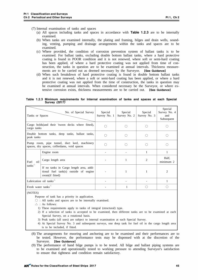
Pt 1 Classification and Surveys
Ch 2 Periodical and Other Surveys Pt 1, Ch 2
Rules for the Classification of Steel Ships 2017 45
(7) Internal examination of tanks and spaces(a) All spaces including tanks and spaces in accordance with Table 1.2.3 are to be internally
examined.(b) When tanks are examined internally, the plating and framing, bilges and drain wells, sound-
ing, venting, pumping and drainage arrangements within the tanks and spaces are to be examined.
(c) Where provided, the condition of corrosion prevention system of ballast tanks is to be examined. For ballast tanks, excluding double bottom ballast tanks, where a hard protective coating is found in POOR condition and it is not renewed, where soft or semi-hard coating has been applied, of where a hard protective coating was not applied from time of con-struction, the tanks in question are to be examined at annual intervals. Thickness measure-ments are to be carried out as deemed necessary by the Surveyor. 【See Guidance】
(d) When such breakdown of hard protective coating is found in double bottom ballast tanks and it is not renewed, where a soft or semi-hard coating has been applied, or where a hard protective coating was not applied from the time of construction, the tanks in question may be examined at annual intervals. When considered necessary be the Surveyor, or where ex-tensive corrosion exists, thickness measurements are to be carried out. 【See Guidance】
Table 1.2.3 Minimum requirements for Internal examination of tanks and spaces at each Special Survey (2017)
No. of Special SurveyTanks or Spaces
Special Survey No. 1
Special Survey No. 2
Special Survey No. 3
Special Survey No. 4
and Subsequent
Cargo holds(and their 'tween decks where fitted), cargo tanks
○ ○ ○ ○
Double bottom tanks, deep tanks, ballast tanks, peak tanks ○ ○ ○ ○
Pump room, pipe tunnel, duct keel, machinery spaces, dry spaces, cofferdams, void spaces ○ ○ ○ ○
Fuel oil tanks△
Engine room - - 1 1
Cargo length area - 1 2Half,
minimum 2
If no tanks in Cargo length area, addi-tional fuel tank(s) outside of engine room(if fitted)
- 1 1 2
Lubrication oil tanks△ - - - 1
Fresh water tanks△ - 1 ○ ○
(NOTES)Purpose of tank has a priority in application.
○ : All tanks and spaces are to be internally examined. △ : As follows:
1) These requirements apply to tanks of integral (structural) type.2) If a selection of tanks is accepted to be examined, then different tanks are to be examined at each
Special Survey, on a rotational basis.3) Peak tanks (all uses) are subject to internal examination at each Special Survey.4) At Special Survey No. 3 and subsequent surveys, one deep tank for fuel oil in the cargo length area
is to be included, if fitted.
(8) The arrangements for mooring and anchoring are to be examined and their performances are to be tested. However, the performance tests may be dispensed with at the discretion of the Surveyor. 【See Guidance】
(9) The performance of hand bilge pumps is to be tested. All bilge and ballast piping systems are to be examined and operationally tested to working pressure to attending Surveyor's satisfaction to ensure that tightness and condition remain satisfactory.

Pt 1 Classification and Surveys
Ch 2 Periodical and Other Surveys Pt 1, Ch 2
46 Rules for the Classification of Steel Ships 2017
(10) Fire protection, fire equipment and its operation tests.(11) In tanks to which an approved measure of corrosion control in accordance with Pt 3, Ch 1, Sec 8 is applied, the condition of coating or corrosion protection is to be examined.
(12) For container ships, equipped with container securing arrangements in accordance with Pt 7, Ch 4, 1002. of the Rules, the container securing arrangements are to be examined as follows:(a) Visual inspection for cell guides and securing devices(cracks, fractures, etc. of welds).(b) Confirmation of comparison between on-board record book and securing devices.
(13) Thickness measurement 【See Guidance】
(a) Thickness measurements are to be carried out in accordance with Table 1.2.4. The Surveyor may extend the thickness measurements as deemed necessary. When thickness measurements indicate substantial corrosion, the extent of thickness measurements is to be increased to determine areas of substantial corrosion. Table 1.2.5 may be used as guidance for these additional thickness measurements. These extended thickness measurements are to be carried out before the survey is credited as completed.
(b) For the ships specified by the Society, the longitudinal strength is to be evaluated after car-rying out the thickness measurements in accordance with the requirement specified in (a) above. However, the only thickness measurement records which have been measured within one(1) year period from the date of the longitudinal strength evaluation shall be considered valid.

Pt 1 Classification and Surveys
Ch 2 Periodical and Other Surveys Pt 1, Ch 2
Rules for the Classification of Steel Ships 2017 47
Table 1.2.4 Minimum requirements for Thickness Measurements at Special Survey
1. General Ships
Special SurveyNo. 1
Special SurveyNo. 2
Special SurveyNo. 3
Special Survey No. 4and Subsequent
1. Suspect areas throughout the vessel
1. Suspect areas throughout the vessel
2. One transverse sec-tion of deck plat-ing in way of a cargo space within the amidships 0.5
1. Suspect areas throughout the vessel
2. Two transverse sections within the amidships 0.5 in way of two different cargo spaces4), 5), 6), 7)
3. All cargo hold hatch cov-ers and coamings(plating and stiffeners)9)
4. Internals in forepeak and afterpeak tanks
5. All transverse bulkheads in all cargo tanks8)
6. All transverse bulkheads in all ballast tanks8)
1. Suspect areas throughout the vessel2. A minimum of three transverse sec-
tions in way of cargo spaces within the amidships 0.5 5), 6), 7)
3. All cargo hold hatch covers and coamings (plating and stiffeners)9)
4. Internals in forepeak and aftpeak tanks
5. All exposed main deck plating full length
6. Representative exposed superstructure deck plating (poop, bridge and forecastle deck)
7. Lowest strake and strakes in way of 'tween decks of all transverse bulkheads in cargo spaces together with internals in way
8. All wind and water strakes, port and starboard, full length
9. All keel plates full length. Also, additional bottom plates in way of cofferdams, machinery space and aft end of tanks
10. Plating of seachests. Shell plating in way of overboard discharges as considered necessary by the attend-ing Surveyor
11. All transverse bulkheads and one web frame ring in all cargo tanks8)
12. All transverse bulkheads and all web frame ring in all ballast tanks8)
(NOTES)1) In application to this table, General Ships means ships except Other Ships in Table 1.2.4, 2.2) Thickness measurement locations are to be selected to provide the best representative sampling of areas
likely to be most exposed to corrosion, considering cargo and ballast history and arrangement and con-dition of protective coatings.
3) Thickness measurements of internals may be specially considered by the Surveyor if the hard protective coating is in GOOD condition.
4) For ships more than 100 meters in length, at Special Survey No. 3, thickness measurements of exposed deck plating within amidship 0.5 may be required.
5) For ships less than 100 meters in length, the number of transverse sections required at Special Survey No. 3 may be reduced to one (1), and the number of transverse sections required at Special Survey No. 4 and subsequent may be reduced to two (2).
6) For the pure car carrier, the extent of thickness measurement for transverse sections may be considered as follows:
- Exposed deck plate, side shell plate, bottom shell plate, inner bottom plate and longitudinal members in double bottom spaces.
7) Where the evaluation of longitudinal strength is required, all longitudinal structural members at the corre-sponding sections are to be gauged.
8) This requirement is to be applied only for tankers(including barges) carrying liquid cargo.9) Subject to cargo hold hatch covers of approved design which structurally have no access to the internals,
thickness measurement shall be done of accessible parts of hatch covers structures.

Pt 1 Classification and Surveys
Ch 2 Periodical and Other Surveys Pt 1, Ch 2
48 Rules for the Classification of Steel Ships 2017
Table 1.2.4 Minimum requirements for Thickness Measurements at Special Survey (continued)
2. Other Ships
Special Survey No. 1
Special SurveyNo. 2
Special SurveyNo. 3
Special Survey No. 4and Subsequent
1. Suspect areas throughout the vessel
1. Suspect areas throughout the vessel
2. One transverse section of deck plating5), side shell plating and bottom plating within the amidships 0.5
1. Suspect areas throughout the vessel
2. Two transverse sec-tions of deck plating5), side shell plating and bottom plating within the amidships 0.5
3. Internals in forepeak and afterpeak tanks
1. Suspect areas throughout the vessel
2. Two transverse sections of side shell plating within the amidships 0.5
3. Full length,1) All exposed main deck plating5)
2) Representative exposed superstructure deck plating(poop, bridge and fore-castle deck)
3) Selected wind and water strakes4) Bottom plating5) Flat keel plating
4. Internals in forepeak and aftpeak tanks
(NOTES)1) In application to this table, Other Ships means the ship specified as follows except Special Purpose Ship -
Waste in Annex 1-1, 1.1 of the Guidance relating to the Rules. - the ship type 12, 13 - the ship less than 500 GT and not engaged on international voyages among ship type 15, 16, 17, 19,
20 and 26 to 302) Thickness measurement locations are to be selected to provide the best representative sampling of areas
likely to be most exposed to corrosion.3) Thickness measurements of internals may be specially considered by the Surveyor if the hard protective
coating is in GOOD condition.4) When the evaluation of longitudinal strength is required, all longitudinal members at the corresponding sec-
tions are to be gauged.5) For fishing vessel, thickness measurement requirements in way of deck(gutter water way part and hatch
coaming part) may be modified at the discretion of the Surveyor if the structure remains effectively pro-tected against corrosion by a permanent type special coating.
Structural Member Extent of Measurement Pattern of Measurement
Plating Suspect area and adjacent plates 5 point pattern over 1 m
Stiffeners Suspect area 3 measurements each in line across web and flange
Table 1.2.5 Requirements for extent of thickness measurement at those areas of substantial corrosion

Pt 1 Classification and Surveys
Ch 2 Periodical and Other Surveys Pt 1, Ch 2
Rules for the Classification of Steel Ships 2017 49
(14) Tank testing(a) Tank testings are to be carried out in accordance with Table 1.2.6.(b) Tanks may be tested afloat at the discretion of the Surveyor, provided that the internal ex-
amination of the bottom is also carried out afloat.
Table 1.2.6 Minimum requirements for tank testing
No. of Special Survey
Tanks
Special Survey No. 1
Special Survey No. 2
Special Survey No. 3
Special Survey No. 4and Subsequent
Double bottom tank, deep tank, bal-last tank, peak tank and other tank(including holds adopted for the car-riage of salt water ballast)
○ ○ ○ ○
Fuel oil tank, lubrication oil tank, fresh water tank
△ △ △ △
(NOTES) 1. Purpose of tank has a priority in application.
2. Boundaries of tanks are to be tested with a head of liquid to the top of air pipes or to near the top of hatches for ballast/cargo holds. Boundaries of fuel oil, lube oil and fresh water tanks are to be tested with a head of liquid to the highest point that liquid will rise under service conditions.
3. ○ : All tanks are to be tested. △ : Tank testing of fuel oil, lube oil and fresh water tanks may be specially considered based on a sat-
isfactory external examination of the tank boundaries, and a confirmation from the Master stating that the pressure testing has been carried out according to the requirements with satisfactory results.
4. For the cargo tanks(except cargo tanks for the liquefied natural gas), tests may be dispensed with, provided after an external and internal examination of the tanks, the Surveyor is satisfied with the condition of the tanks.
5. The Surveyor may extend the testing as deemed necessary. 【See Guidance】
(15) Where considered necessary by the Surveyor, the effectiveness of shell plating, watertight bulk-heads, shaft tunnels, watertight doors and the closing appliances of openings on superstructure end bulkheads is to be confirmed. 【See Guidance】
(16) Engine room structure is to be examined. Particular attention is to be given to tank tops, shell plating in way of tank tops, brackets connecting side shell frames and tank tops, and engine room bulkheads in way of tank top and bilge wells. Particular attention is to be given to the sea suctions, sea water cooling pipes and overboard discharge valves and their connections to the shell plating. Where wastage is evident or suspect, thickness measurements are to be carried out, and renewals or repairs made when wastage exceeds allowable limits.

Pt 1 Classification and Surveys
Ch 2 Periodical and Other Surveys Pt 1, Ch 2
50 Rules for the Classification of Steel Ships 2017
(17) For all ships except for passenger ships, automatic air pipe heads are to be completely exam-ined(both externally and internally) as indicated in Table 1.2.7. For designs where the inner parts cannot be properly inspected from outside, this is to include removal of the head from air pipe. Particular attention is to be paid to the condition of the zinc coating in heads constructed from galvanized steel.
Table 1.2.7 Survey requirements for automatic air pipe heads at Special Survey
Special Survey No. 11), 2) Special Survey No. 21), 2) Special Survey No. 3and Subsequent3)
․ Two air pipe heads, one port and one starboard, located on the exposed decks in the forward 0.25 , preferably air pipes serving ballast tanks
․ Two air pipe heads, one port and one starboard, on the exposed decks, serving spaces aft of 0.25 , preferably air pipes serving ballast tanks
․ All air pipe heads located on the exposed decks in the forward 0.25
․ At least 20% of air pipe heads on the exposed decks serving spaces aft of 0.25 , preferably air pipes serving ballast tanks
․ All air pipe heads located on the exposed decks
(NOTES)1) The selection of air pipe heads to be examined is left to the attending Surveyor.2) According to the results of this examination, the Surveyor may require the examination of other heads lo-
cated on the exposed deck.3) Exemption may be considered for air pipe heads where there is substantial evidence of replacement after the
last Special Survey.
(18) Where a stability instrument is provided on-board, all approved test loading conditions are to be examined.
(19) For ships provided with the equipment employed in the mooring of ships at single point mooring specified in Pt 4, Ch 10, 101. 3 and assigned the additional class notation "EQ-SPM", the function and deformation condition of this equipment employed in the mooring of ships at single point mooring and hull supporting structures are to be closely checked and confirmed its satisfactory conditions. Where deemed necessary, non-destructive examinations may be required. 【See Guidance】
2. For ships subject to the enhanced survey programme such as bulk carriers, oil tankers and chemical tankers, etc., in addition to items of Par 1 the additional requirements in accordance with Ch 3 are to be taken. However, if the duplicated survey items are exist, these are not need to be applied twice.
3. For additional requirements applicable to water level detectors fitted on single hold cargo ships, re-fer Sec 14.
4. In addition to Par 1, Ch 14 is also to be taken for general dry cargo ships and Ch 15 is also to be taken for liquefied gas carriers. However, if the duplicated survey items are exist, these are not need to be applied twice.
5. In addition to Par 1, Ch 16 is also to be taken for shell and inner doors, etc. of RoRo ships. However, if the duplicated survey items are exist, these are not to be applied twice.
6. In addition to Par 1, relevant requirements of Ch 17 and/or Ch 18 are also to be taken if applicable.
404. Fire-extinguishing appliances
For fire-extinguishing appliances, the survey is to be in accordance with the Guidance relating to the Rules. 【See Guidance】

Pt 1 Classification and Surveys
Ch 2 Periodical and Other Surveys Pt 1, Ch 2
Rules for the Classification of Steel Ships 2017 51
Section 5-1 Special Survey(Machinery, Electrical Installations and Additional Installations)
501. Due range
The due range of Special Survey(Machinery, electrical installations and additional installations) is to be complied with the requirements specified in 401.
502. Requirements of survey
At the Special Survey(Machinery, electrical installations and additional installations), in addition to the requirements for Intermediate Survey, the following requirements are to be complied with.
1. Requirements of main engines and auxiliary engines
(1) At the Special Survey for main engines, the following requirements are to be conformed to with respect to the type of engine, where deemed necessary by the Surveyor, control devices, govern-ing devices and safety devices are to be tested. 【See Guidance】
(a) For internal combustion engines, cylinders, cylinder covers, pistons, piston rods and connect-ing rods, crosshead(including pins, bearings and guides), crank shafts and all bearings, elas-ticity couplings, cam shafts and their driving gears, essential valves and valve arrangements, fuel oil pumps and fittings, scavenging pumps, scavenging blowers, superchargers, inter-coolers, filter or oil separators and safety devices, clutches, reverse gears, attached pumps and coolers, crank cases and explosion relief devices are to be opened up and examined, and the deflections of crank arms are to be measured. And, effectiveness of vibration damp-er is to be confirmed and balancers are to be examined.However, those total running hours not more than the overhauling time recommended by the manufacturer since the previous overhauling survey, the survey is to be in accordance with the Guidance relating to the Rules. 【See Guidance】
(b) Examinations for high-rotating-speed internal combustion engines of specific construction such that complete engine overhaul is required for surveys may be in accordance with the Guidance relating to the Rules. 【See Guidance】
(c) Where the propulsion steam turbines are of a well known type, and fitted with rotor posi-tion indicators and vibration indicators of an approved type, as well as measuring equipment of steam pressure at proper locations along the steam flow, and the arrangements for change over in case of emergency operation of the plant are readily operable, the first Special Survey may be limited to be examination of rotor bearings, thrust bearings and flexible cou-plings, provided the Surveyor has been satisfied from operation service records and power trials subsequent to the survey, that the turbine plant is in good working condition. Turbine casings should be opened at the next second Special Survey and subsequent Special Surveys.
(2) For auxiliary engines, the requirements corresponding to those of the main engine are to be conformed to.
2. Requirements of machinery except for main engines and auxiliary engines
(1) All shafts(except the propeller and stern tube shafts), thrust blocks and line shaft bearings are to be examined. The lower halves of bearings need not be exposed, if alignment and wear are found satisfactory.
(2) Reduction gears are to be examined. Where deemed necessary by the Surveyor, reduction gears are to be opened up and the gear wheels, pinions, gear shafts and bearings are to be examined. 【See Guidance】
(3) Air compressors with their intercoolers, filters and/or oil separators and safety devices, and all pumps and components used for essential services are to be opened up as considered necessary by the Surveyor and examined. 【See Guidance】
(4) Operational conditions of steering gear are to be examined. Where deemed necessary by the Surveyor, main parts are to be opened up and examined. 【See Guidance】
(5) Operational conditions of windlass, mooring winches and cargo winches are to be examined. Where deemed necessary by the Surveyor, main parts of them are to be opened up and examined. 【See Guidance】
(6) Evaporators are to be opened up and examined. Their safety valves are also to be checked un-der working condition.
Pt 1 Classification and Surveys
Ch 2 Periodical and Other Surveys Pt 1, Ch 2
52 Rules for the Classification of Steel Ships 2017
(7) The foundation bolts and chocks of main and auxiliary engines, gear casings, thrust blocks and line shaft bearings are to be examined.
(8) All air receivers and other pressure vessels for essential services together with their mountings and safety devices are to be opened up and examined internally and externally. If internal ex-amination of them is not practicable, they are to be tested hydraulically to 1.5 times the work-ing pressure, and if considered necessary by the Surveyor, performance test of safety valves for the above mentioned devices is to be carried out. 【See Guidance】
(9) Pumping and piping arrangements(a) Valves, cocks and strainers of the bilge system including the emergency bilge suction valves
are to be examined. And where deemed necessary by the Surveyor, opening up examination of above items or effectiveness test of the bilge system is to be carried out. 【See Guidance】
(b) The fuel oil, feed and lubricating oil systems, the ballast pipe connections and blanking ar-rangement to the ballast holds and all filters, heaters, coolers and condensers for essential services are to be opened up and examined. The pressure tests may be carried out, includ-ing safety devices, where deemed necessary by the Surveyor. 【See Guidance】
(c) Fuel oil tanks which do not form part of the ship's structure are to be examined internally and externally and, if considered necessary by the Surveyor, they are to be tested to the pressure specified for new tanks. At the Special Survey No. 1, internal examination of the tanks may be dispensed with, provided they are found satisfactory in external examination. All mountings, fittings and remote controls are to be examined as far as practicable. 【See Guidance】
(10) Where deemed necessary by the Surveyor, the performance tests of pressure gauges, revolu-tions and thermometers are to be made. 【See Guidance】
(11) Where automatic and remote controls are fitted up for essential machinery, they are to be test-ed to demonstrate that they are in good working order.
(12) Main steam pipes, where considered necessary by the Surveyor are to be examined after re-moving the lagging indicated by the Surveyor. The thickness of pipes is also to be checked as necessary. 【See Guidance】
(13) The following safety inspections are to be carried out for the cargo refrigerating machinery given in Pt 5, Ch 6, 1201. 1.
(a) Leaks of the refrigerants are to be tested while the machinery is examined in running condition.
(b) Coils of coil type condensers and evaporators, shell tube type condensers and shells of re-ceivers are to be tested at a pressure of at least 90 percent of the design pressure. Where, however, relief valves attached to them are adjusted to a pressure less than the design pres-sure, the test pressure may be reduced to a pressure of 90 percent of the pressure to which the relief valves are adjusted. The above pressure test may be dispensed with except for those using NH3 or CH3Cl as refrigerants.
(14) Essential parts of incinerators are to be opened up and internally examined.
3. Electrical equipment
In the Special Survey for electrical equipment, the following requirements are to be conformed to.(1) Main and emergency switchboards, section panels, and sub-distribution fuse panels are to be ex-
amined and overcurrent protective devices and fuses inspected to verify that they provide suit-able protection for their respective circuits.
(2) The generators are to be running under the loaded condition, either separately or in parallel and the performances of speed governors, switches and circuit breakers are to be tested.
(3) The insulation resistances of generators, switchboards, motors, cables and other electrical equip-ment are to be tested and adjusted if it is found not to comply with the requirements given in Pt 6, Ch 1, 1701. 1. However, this test may be dispensed with, where it is found that the measured records remain efficient and they comply with the requirements specified in Pt 6, Ch 1, 1701. 1.
(4) Where deemed necessary by the Surveyor, the lighting arrangements, internal communication and signalling systems, mechanical ventilation systems, and other electrical equipment are to be test-ed for effectiveness. 【See Guidance】
4. The surveys for water jet propulsion systems and azimuth or rotatable thruster are to be carried out in accordance with the Guidance relating to the Rules. 【See Guidance】

Pt 1 Classification and Surveys
Ch 2 Periodical and Other Surveys Pt 1, Ch 2
Rules for the Classification of Steel Ships 2017 53
5. The surveys for additional installations(cargo refrigerating installations, cargo handling appliances, automation and remote control systems, dynamic positioning system, navigation bridge systems, hull monitoring systems, diving system, high voltage shore connection systems, cargo vapour emission control systems and ballast water management, etc.) are to be carried out in accordance with the requirements specified in Pt 9, etc.
6. Gas-fuelled ships other than ships carrying liquefied gases in bulk and ships carrying CNG in bulk are also to meet with the requirements in Ch 2, 203. of the Guidance for Gas-fuelled Ships, in addition to the requirements in this section.
7. Where CMS specified in Sec 9 is applied, the performance test for safety devices including the items other than CMS are to be surveyed.
8. A mooring trial is to be carried out to attending Surveyor's satisfaction to confirm satisfactory oper-ation of main and auxiliary machinery.
9. In addition to Par 1 through Par 8, relevant requirements of Ch 18 are also to be taken if applicable.

Pt 1 Classification and Surveys
Ch 2 Periodical and Other Surveys Pt 1, Ch 2
54 Rules for the Classification of Steel Ships 2017
Section 5-2 Special Survey(Additional Requirements to Ship Types)
The Special Survey(Additional requirements to ship types), in addition to the requirements for Intermediate Survey, shall be carried out as follows.
1. Oil tankers(including tankers) :
The additional requirements are to be surveyed as follows,(1) For pump room, in particular, the foundations and gland seals of pumps, stuffing box, sealing
arrangements of all penetrations of bulkheads and ventilating arrangements are to be examined.(2) Condition of the inner surface of the bottom plating in cargo tanks is to be examined in order
to ascertain that there is no excessive pitting of the plating.(3) Bell mouths of the cargo suction pipes in cargo tanks are to be removed to enable examination
of the shell plating and bulkheads in that vicinity.(4) All piping systems in the tanks and spaces, cargo oil pipes on weather deck, breather valves,
flame screens on vents, purge systems, gas free systems, inert gas systems and other piping sys-tems are to be examined. When considered necessary by the Surveyor, pressure tests and/or gaugings for pipings are to be carried out. 【See Guidance】
(5) For inert gas system, the following items are to be examined, when appropriate, opened-up. 【See Guidance】
(A) Major parts of inert gas scrubbers.(B) Major parts of inert gas blowers.(C) Major parts of non-return devices(e.g., deck water seal).(D) Major parts of flue gas isolating valves.(E) Major parts of P/V breakers.
2. Chemical tankers :
The additional requirements are to be surveyed as follows,(1) Foundation of cargo containments, including supports, keys and anti-rolling/anti-pitching devices
are to be examined.(2) Closing and sealing devices of the domes of cargo containments, where they penetrate decks are
to be examined.(3) The pumps are to be opened and examined.
3. Liquefied gas carriers :
The additional requirements are to be surveyed as follows,(1) Cargo containment survey
(A) All cargo tanks are to be examined internally.(B) Special attention is to be paid to the cargo tank and insulation in way of chocks, supports,
keys and other parts which consist of the foundation of tanks. Removal of insulation may be required in order to verify the condition of the tank or the insulation itself if found nec-essary by the Surveyor. Where the arrangement is such that the insulation cannot be exam-ined, the surrounding structure of the wing tanks, double bottom tanks and cofferdams are to be examined for cold spots when the cargo tanks are in the cold condition unless voyage record together with the instrumentation give sufficient evidence of the integrity of the in-sulation system. 【See Guidance】

Pt 1 Classification and Surveys
Ch 2 Periodical and Other Surveys Pt 1, Ch 2
Rules for the Classification of Steel Ships 2017 55
(C) Non-destructive testNon-destructive testing is to supplement cargo tank inspection with special attention to be given to the integrity of the main structural members, tank shell and highly stressed parts, including welded connection as deemed necessary by the Surveyor. However, for type C tanks, this does not mean that non-destructive testing can be dispensed with totally. The fol-lowing items are, inter alia, considered as highly stressed parts: 【See Guidance】
- cargo tank supports and anti-rolling/anti-pitching devices- web frames or stiffening rings- swash bulkhead boundaries- dome and stump connections to tank shell- foundations for pumps, towers, ladders, etc.- pipe connections
For the independent tank type B, the extent of non-destructive testing shall be given in a programme specially prepared for the cargo tank design.
(D) The tightness of all cargo tanks is to be verified by an appropriate procedure. Provided that the effectiveness of the ships's gas detection equipment has been confirmed, it will be ac-ceptable to utilize this equipment for the tightness test of independent tanks below deck.
(E) Where findings of (A) to (D) or an examination of the voyage records raises doubts as to the structure integrity of a cargo tank, a hydraulic or hydro-pneumatic test is to be carried out. For integral tanks and for independent tank type A and B, the test pressure is to be carried out in accordance with proper pressure based on design of each tank. For in-dependent tank type C, the test pressure is not to be less than 1.25 times the MARVS.
(F) At every other special survey(i.e., 2nd, 4th, 6th, etc) all independent cargo tank type C are to be either:(a) Hydraulically or hydro-pneumatically tested to 1.25 times MARVS, followed by non-de-
structive testing in accordance with (C), or(b) Subjected to a thorough, planned non-destructive testing. This testing is to be carried
out in accordance with a programme specially prepared for the tank design. If a special program does not exist, the following applies:
- cargo tank supports and anti-rolling/anti-pitching devices- stiffening rings- Y-connections between tank shell and a longitudinal bulkhead of tanks- swash bulkhead boundaries- dome and stump connections to the tank shell- foundations for pumps, towers, ladders etc.- pipe connections
At least 10 % of the length of the welded connections in each of the above mentioned areas is to be tested. This testing is to be carried out internally and externally as applicable. Insulation is to be removed as necessary for the required non-destructive test.
(2) As far as practicable all hold spaces and hull insulation(if provided), secondary barriers and tank supporting structures are to be visually examined. The secondary barriers is to be checked for their effectiveness by means of a pressure/ vacuum test, a visual inspection or another acceptable method.
(3) Membrane and semi-membrane tank(A) For membrane and semi-membrane tanks systems, inspection and testing are to be carried
out in accordance with programmes specially prepared in accordance with an approved method for the actual tank system.
(B) For membrane containment systems, a tightness test of the primary and secondary barrier shall be carried out in accordance with the system designers’ procedures and acceptance criteria as approved by the classification society. Low differential pressure tests may be used for monitoring the cargo containment system performance, but are not considered an acceptable test for the tightness of the secondary barrier.
(C) For membrane containment systems with glued secondary barriers if the designer’s thresh-old values are exceeded, an investigation is to be carried out and additional testing such as thermographic or acoustic emissions testing should be carried out.
(4) The pressure/vacuum relief valve, rupture disc and other pressure relief devices for interbarrier spaces and hold spaces are to be opened, tested and readjusted as necessary, depending on their design. 【See Guidance】

Pt 1 Classification and Surveys
Ch 2 Periodical and Other Surveys Pt 1, Ch 2
56 Rules for the Classification of Steel Ships 2017
(5) The pressure relief valves for the cargo tanks are to be opened for examination, adjusted, func-tion tested, and sealed. If the cargo tanks are equipped with relief valves with non-metallic membranes in the main or pilot valves, such non-metallic membranes are be replaced. Where a proper record of continuous overhaul and retesting of individually identifiable relief valves is maintained, consideration will be given to acceptance on the basis of opening, internal examina-tion, and testing of a representative sampling of valves, including each size and type of lique-fied gas or vapor relief valve in use, provided there is logbook evidence that the remaining valves have been overhauled and tested since crediting of the previous Special Survey.
(6) Piping systems(A) The cargo, liquid nitrogen and process piping systems, including valves, actuators, compensators
etc. are to be opened for examination as deemed necessary. Insulation is to be removed as deemed necessary to ascertain the condition of the pipes. If the visual examination raises doubt as to the integrity of the pipelines, a pressure test at 1.25 times the MARVS for the pipeline is to be carried out. After reassembly the complete piping systems are to be tested for leaks. 【See Guidance】
(B) The pressure relief valves are to be function-tested. A random selection of valve is to be opened for examination and adjusted.
(7) ComponentsCargo pumps, compressors, process pressure vessels, liquid nitrogen tanks, heat exchangers and other components, including prime movers, used in connection with cargo handling and methane boil-off burning are to be examined.
(8) Miscellaneous(A) Systems for removal of water or cargo from interbarrier spaces and holds are to be exam-
ined and tested as deemed necessary. 【See Guidance】
(B) All gas-tight bulkhead are to be inspected. The effectiveness of gas-tight shaft sealing is to be verified.
(C) Hose and spool pieces used for segregation of piping systems for cargo, inert gas and bilg-ing are to be examined.
(D) It is to be verified that all cargo piping system are electrically bonded to the hull.

Pt 1 Classification and Surveys
Ch 2 Periodical and Other Surveys Pt 1, Ch 2
Rules for the Classification of Steel Ships 2017 57
Section 6 Docking Survey
601. Due range 【See Guidance】
1. There is to be a minimum of two examinations of the outside of the ship's bottom and related items during each five-year Special Survey period. One such examination is to be carried out in conjunction with the Special Survey. In all cases the interval between any two such examinations is not to exceed 36 months.
2. Notwithstanding the requirements specified in Par 1 above, for passenger ships, submersibles, nu-clear ships, hydrofoils, air cushion vehicles, high speed crafts, the docking survey is to be a part of the Special, Intermediate or Annual Survey. But the Docking Survey may be subject to the re-quirements as provided separately by the Society.
3. In addition to Par 1 through Par 2, relevant requirements of Ch 18 are also to be taken if applicable.
602. Extension of survey
The Docking Survey may be extended upon the request of the Owner as follows:1. Where the Special Survey is extended in accordance with 401. 1 and 2, an extension of Docking
Survey can be granted in accordance with the requirements specified in 401. 1 (4).
2. An extension of Docking Survey of 3 months beyond the due date can be granted upon the appro-val of the Society in exceptional circumstances defined in 401. 1.
603. Requirements of survey
1. The ship is to be placed in a drydock or on a slipway, and it is to be placed on blocks of suffi-cient height and with the necessary staging to permit the examination of elements such as shell plating including bottom and bow plating, stern frame and rudder, sea chests and valves, propeller, etc.
2. The shell plating is to be examined for excessive corrosion, or deterioration due to chafing or con-tact with the ground and for any undue unfairness or buckling. Special attention is to be paid to bilge keels. 【See Guidance】
3. Rudder, rudder pintles, rudder shafts and couplings and stern frame are to be examined. If consid-ered necessary by the Surveyor, the rudder is to be lifted or the inspection plates removed for the examination of pintles. The clearance in the rudder bearings is to be ascertained and recorded. If it exceeds the values given below, the bush is to be adjusted. Where applicable, pressure test of the rudder may be required as deemed necessary by the Surveyor. 【See Guidance】
Pintle (Diameter of Pintle : ) Allowable clearance
≤ 50 mm 3.0 mm 50 mm < ≤ 100 mm 5.0 mm
100 mm < 0.01 + 4.0 mmNeck bearing (Diameter of rudder stock : ) 0.01 + 2.0 mm
4. Sea chests and their gratings, sea connections and overboard discharge valves and cocks and their fastenings to the hull or sea chests are to be examined. Valves and cocks could be opened up at Docking Survey as a part of Special Survey unless considered necessary by the Surveyor. 【See Guidance】

Pt 1 Classification and Surveys
Ch 2 Periodical and Other Surveys Pt 1, Ch 2
58 Rules for the Classification of Steel Ships 2017
5. The propeller is to be examined. The efficiency of the oil gland, if fitted, is to be ascertained and clearance or weardown in the stern bush are to be measured. For controllable pitch propellers and special type propellers, the sealing and tightness conditions are to be ascertained and recorded. In the case where the pitch control device is fitted, it is to be ascertained that the device is in good working order. However, if considered necessary by the Surveyor, the device is to be opened up for further examination. 【See Guidance】
6. Visible parts of side thrusters and anti-rolling devices are to be examined. Other propulsion systems which also have manoeuvring characteristics (such as waterjet propulsion systems, azimuth or rotat-able thrusters/directional propellers, vertical axis propellers) are to be examined externally with fo-cus on the condition of gear housing, propeller blades, bolt locking and other fastening arrange-ments and sealing arrangement of propeller blades, propeller shaft and steering column shall be verified. Furthermore the surveys are to be carried out in accordance with the Guidance relating to the Rules. 【See Guidance】
7. The clearance between the propeller shaft and the after bearing of stern tube as well as the shaft bracket if fitted is to be measured for water-lubricated stern tube bearings, and if it exceeds the values given below, the bearing is to be replaced or repaired. Stern tube shafts are also to be com-ply with these requirements.
Diameter of propeller shaft Allowable clearance
≤ 230 mm 6.0 mm 230 mm < ≤ 305 mm 8.0 mm
305 mm < 9.5 mm
8. For ships with IWS notation, the requirements to assign the IWS notation specified in 604. 3. (8) are to be confirmed for continuing compliance.
9. For ships with EDD notation, the requirements to assign the EDD notation specified in 605. 2. are to be confirmed for continuing compliance.

Pt 1 Classification and Surveys
Ch 2 Periodical and Other Surveys Pt 1, Ch 2
Rules for the Classification of Steel Ships 2017 59
604. In-water Survey
1. The Society may accept an In-water Survey in lieu of the intermediate docking between Special Surveys required in a five year period on ships less than 15 years of age. Special consideration of the Society is to be given to ships of 15 years of age or over before being permitted to have such In-water Survey. For ships with ESP notation of 15 years of age and over, such In-water Surveys are not to be allowed. 【See Guidance】
2. In-water Survey in lieu of the Docking Survey may be restricted at the discretion of the Society if there are record or indication of abnormal deterioration, existing outstanding recommendation for re-pairs, or damage to underwater part of the shell plating, the rudder, the propeller, the propeller shaft, sea connections or overboard discharge valves.
3. Where an In-water Survey in lieu of the intermediate docking between Special Surveys is desired, the survey procedures are as follows:(1) Plans and documents
The following plans and documents are to be submitted to the Surveyor and the divers.(a) Plans of shell plating below waterline showing the location and sizes of shell openings, lo-
cation of bottom plugs, location of appendages, location of measuring position of navigation instruments, location of bilge keels, location of water-tight and oil-tight bulkheads, and loca-tion of welded seams and butts including any doublers and straps.
(b) Detailed information or drawing of constructions and arrangements indicated in (2) below.(2) Constructions, arrangements, etc.
Where an In-water Survey in lieu of the docking survey is desired, the following construction and arrangements are to be made.(a) Rudder arrangements are to be such that rudder pintle clearances can be checked.(b) Rope-guard ring plates are to be of such construction as to facilitate the inspection of shaft-
ings between propeller hubs and stern frame boss.(c) In case of water lubricated stern tube bearings, the construction is to be suitable for con-
firmation and measurement of the clearance between the propeller shafts and these bearings.(d) In case of oil lubricated stern tube bearings, suitable means of ascertaining the performances
of stern tube bearings including oil sealing devices are to be provided.(3) Condition of survey
(a) In the lightest draught condition as possible.(b) The condition of hull below waterline and hull bottom is can be ascertained.(c) The sea state conditions such as tidal stream, current, swell, etc. at the location of the sur-
vey are to be calm and peaceful. The in-water visibility and the cleanliness of the hull be-low the waterline is to be clear enough to permit a meaningful examination which allows the Surveyor and diver to determine the condition of the plating, appendages and the welding.
(d) The distance between hull bottom and sea bottom is to be enough.(e) In-water Survey is to be carried out by a company approved by the Society.
(4) Survey extent(a) The In-water Survey is to provide the information normally obtained from a Docking
Survey. Special consideration shall be given to ascertaining rudder bearing clearances and stern bush clearances of oil stern bearings based on a review of the operating history, on board testing and stern oil sample reports. These considerations are to be included in the proposals for In-water Survey which are to be submitted in advance of the survey so that satisfactory arrangements can be agreed with the Society.
(b) General inspection for sea connections and overboard discharge valves, at inside of the ship

Pt 1 Classification and Surveys
Ch 2 Periodical and Other Surveys Pt 1, Ch 2
60 Rules for the Classification of Steel Ships 2017
(5) Practice of In-water Survey(a) In-water Survey is to be carried out in the presences of the Surveyor and the Owner.(b) All preparations required for an In-water Survey are to be made by the Owner.(c) The Surveyor shall confirm the preparation for survey and the operational condition of
In-water Survey equipment.(d) The Surveyor shall know the status of the ship in advance, and inform the diver before div-
ing of survey items and measurement.(e) The means are to be provided to maintain good communication between the Surveyor and
the underwater diver at all times.(f) The Surveyor may confirm the status of survey by in-water photographs, cameras, television
monitors and other means.(g) In a job site, the results of In-water Survey shall be immediately reported to the Owner,
and the Owner and diver sign their names on the Diving Report, confirming the result.(6) Diving report
The following items are to be stated in the diving report.(a) Name of diving company(b) Name of diver and licence No.(c) Date and place of survey(d) Name of equipment used in In-water Survey(e) Name of ship, classification character and notations, gross tonnage, port of registry, owner
of ship(f) Drafts(forward and aft)(g) Contents and results of survey(damage configuration and status, etc.)
(7) Further surveys(a) The Surveyor may require the further examination such as internal examinations, thickness
measurement, etc. where deemed necessary by the Surveyor as a result of the In-water Survey 【See Guidance】
(b) If the result of In-water Survey reveals damage or deterioration that requires early attention, the Surveyor may require that the ship be dry-docked in order that a detailed survey can be undertaken and the necessary repairs carried out.
(8) For a ship with IWS of additional special feature notation, the following requirements are to be complied with, in addition to the requirements specified in preceding (1) to (7).(a) The plans and documents specified in (1) and (b) to (d) below are to be submitted to the
Society for approval, and are to be kept on board.(b) Anodes are to be attached in such a manner as to be easily replaced when necessary.(c) To the shell plating below load waterline, provision is to be made for ready identification
of the position of bulkhead.(d) Ships contracted for construction or intended to have IWS notation newly, on or after 1
July 2011, are to be complied with the following requirements additionally.(i) A suitable means of ascertaining the position and identity of each blade of the pro-
pellers are to be provided.(ii) Hinged gratings are to be installed on all sea chests and constructed so as to facilitate
opening and closing by the diver.(iii) Markings indicating the position of longitudinal and transverse bulkheads and the names
of interior spaces, sea suction and overboard discharge openings on the shell plating be-low the load water line are to be provided so that the diver is able to orient his/her position relative to the ship. Such markings may be consist of a weld bead or center punch, and a contrasting color coating. Other suitable arrangements or means may be considered as equivalent where deemed appropriate by the Society. 【See Guidance】

Pt 1 Classification and Surveys
Ch 2 Periodical and Other Surveys Pt 1, Ch 2
Rules for the Classification of Steel Ships 2017 61
605. Extended Dry-docking Interval System
1. General
(1) The "Extended Dry-docking Interval System" is in any case subject to approval by the relevant flag state. The approval or acceptance of this rule by the relevant flag state doesn't means the approval for the application of Extended Dry-docking Interval System on the relevant ship, and the separate approval by the each relevant flag state is required for the application of Extended Dry-docking Interval System.
(2) The "Extended Dry-docking Interval System" applies to ships with Container Ship notation or Cargo Ship notation and General Dry Cargo Ships specified in Sec 14.
(3) In application to 601. 1, at the request of the Owners, where deemed appropriate by the Society considering survey history, damage history and coating conditions, etc. it is possible un-til the ship reaches 15 years of age to perform the first and second Docking Survey due from the completion date of the Classification Survey during Construction or the completion date of the previous Docking Survey as an In-water Survey, and the third Docking Survey has to be performed in dry-dock or on a slipway within 7.5 years from the completion date of the Classification Survey during Construction or the completion date of the previous Docking Survey. 【See Guidance】
(4) The Owner can apply to join the "Extended Dry-docking Interval System" before the date on which the ship reaches 10 years of age. When the Owner applied to join the "Extended Dry-docking Interval System" after the No.1 Special Survey and the Docking Survey assigned between 10 years to 15 years of age has carried out in dry-dock or on a slipway, the next Docking Surveys can be carried out as Docking Survey and In-water Survey alternately start with In-water Survey.
(5) In the case of a change in Owner or flag, the application of the "Extended Dry-docking Interval System" is to be reconsidered and a Docking Survey may be assigned or required immediately.
(6) The Society reserves the right to suspend the "Extended Dry-docking Interval System" at any time if it is determined that a dry-docking is necessary. 【See Guidance】
(7) The EDD notation shall be assigned as an additional special feature notation to ships carrying out the "Extended Dry-docking Interval System".
2. Necessary requirements
The necessary requirements for implementation of the "Extended Dry-docking Interval System" are as followings.(1) To be applied the Owner's Hull Inspection and Maintenance Program according to Annex 1-13
of the Guidance(2) Ships contracted for construction on or after 1 July 2011 and classed through the Classification
Survey during Construction are to have IWS notation according to 604. 3 (8), and the other ships can be carried out the In-water Survey according to 604. 2 and 3.
(3) To have STCM(stern tube condition monitoring) notation. Ships not assigned STCM notation are to be fitted with a shaft bearing and sealing system of approved design with implementation of regular monitoring procedures
(4) For ships contracted for construction on or after 1 July 2011, the dry film thickness(DFT) of the coating system for shell plating below the load water line excluding antifouling for the shell plating is to be more than 300 and for the other ships it is to be more than 250 . In addition, the anodes are to be fitted and/or the impressed current cathodic protection system is to be installed and maintained.
(5) In lieu of (4) above, the Society may accept the other coating system provided that the coating manufacturer proves with relevant documents that the applied coating system is designed to last for the 7.5 years.
(6) Ballast tanks shall have a corrosion prevention system and to be maintained in GOOD coating condition.
(7) The hull below load waterline is to be free of any recommendation.

Pt 1 Classification and Surveys
Ch 2 Periodical and Other Surveys Pt 1, Ch 2
62 Rules for the Classification of Steel Ships 2017
3. Approval and survey
(1) Documents and approvalFor implementation of the "Extended Dry-docking Interval System" the following documents shall be presented to the Society. The Society will issue an approval document for the "Extended Dry-docking Interval System" after review the presented documents. This approval document is to be placed on-board.(A) Application for “Extended Dry-docking Interval System"(B) Description of the system for the "Extended Dry-docking Interval System" with flow charts
of the system organization within the company(C) Plans and/or information showing the ship is satisfy to the necessary requirements for the
"Extended Dry-docking Interval System" specified in Par 2 above including the followings(a) Manual for the Hull Inspection and Maintenance Program according to Annex 1-13 of
the Guidance(b) Inspection procedures for In-water Survey(c) Procedure for stern tube condition monitoring(d) Coating system for shell plating below the load water line
(D) Other documents as deemed necessary by the Society(2) Implementation survey
(A) Additional to the approval according to (1) above, the implementation survey is to be car-ried out within one year from the date of the approval of the "Extended Dry-docking Interval System" to verify that the "Extended Dry-docking Interval System"is implemented in accordance with the approval document.
(B) During the implementation survey, the attending Surveyor is to check the following items.(a) An approval document for the "Extended Dry-docking Interval System"(b) Documents specified in Par 3 (1) (B) to (D)(c) Whether the Master is familiar with the "Extended Dry-docking Interval System"(d) A random check for compliance of the necessary requirements specified in Par 2 above
including the followings.- Check whether the Owner's Hull Inspection and Maintenance Program specified in Annex 1-13 of the Guidance is operated satisfactorily.
- Check the stern tube condition monitoring- Check the impressed current cathodic protection system, if fitted
(3) Annual audit(A) An annual audit is to be carried out to check the operation of the "Extended Dry-docking
System" at Annual Survey(B) At the annual audit the attending Surveyor is to check the following items.
(a) An approval document for the "Extended Dry-docking Interval System"(b) Documents specified in Par 3 (1) (B) to (D)(c) Whether the Master is familiar with the "Extended Dry-docking Interval System"(d) Check for compliance of the necessary requirements specified in Par 2 above including
the followings.- Check whether the Owner's Hull Inspection and Maintenance Program specified in Annex 1-13 of the Guidance is operated satisfactorily and confirmation of random compartments
- Check the stern tube condition monitoring- Check the impressed current cathodic protection system, if fitted
Pt 1 Classification and Surveys
Ch 2 Periodical and Other Surveys Pt 1, Ch 2
Rules for the Classification of Steel Ships 2017 63
Section 7 Surveys of Propeller Shaft and Stern Tube Shaft, Etc.
701. General 【See Guidance】
1. Unless alternative means are provided to assure the condition of the propeller shaft assembly, these requirements apply to all vessels with conventional shafting fitted with a propeller as follows:(1) from 1 January 2016 for ships delivered on or after 1 January 2016;(2) after the first shaft survey scheduled on or after 1 January 2016, for ships delivered before 1
January 2016. Upon the completion of the first shaft survey scheduled on or after 1 January 2016, the designation of dates for the next shaft survey is to be made based upon this Section.
2. The surveys for water jet propulsion systems and azimuth or rotatable thruster are to be carried out in accordance with the Guidance relating to the Rules.
3. Definitions
(1) Shaft means propeller shaft and tube shaft, and does not include the intermediate shaft which is considered part of the propulsion shafting inside the vessel.
(2) Propeller shaft means the part of the propulsion shaft to which the propeller is fitted.(3) Stern tube shaft means a shaft placed between the intermediate shaft and propeller shaft, nor-
mally arranged within a stern tube or running in open water.(4) Stern tube means a tube or pipe fitted in the shell of a ship at the stern (or rear part of the
ship), below the water-line, through which passes the tube shaft or aftermost section of the pro-peller shaft.
(5) Oil lubricated bearing means a bearing which uses oil to lubricate the bearings and are sealed against the environment(such as seawater) by adequate sealing devices.
(6) Water lubricated bearing means a bearing cooled and lubricated by water(fresh or salt).(7) Closed loop system fresh water lubricated bearing means a bearing which uses fresh water
to lubricate the bearings and are sealed against the environment(such as seawater) by adequate sealing devices.
(8) Open system water lubricated bearing means a bearing which uses fresh water to lubricate the bearings and use water to lubricate the bearings and are exposed to the environment(such as seawater).
(9) Adequate means for protection against corrosion means an approved means for protection of the shaft against corrosion by sea water.
(10) Corrosion resistant shaft is a shaft which is made of approved corrosion resistant material.(11) Stern tube sealing system means the equipment installed on the inboard extremity and, for
closed systems, at outboard extremity of the stern tube.(A) Inboard Seal is the device fitted on the fore part of the sterntube that achieve the sealing
against the possible leakage of the lubricant media in to the ship internal.(B) Outboard seal is the device fitted on the aft part of the sterntube that achieve the sealing
against the possible sea water ingress and the leakage of the lubricant media.(12) Service records are regularly recorded data showing in-service conditions of the shaft and
may include, as applicable: lubricating oil temperature, bearing temperature and oil consumption records (for oil lubricated bearings) or water flow, water temperature, salinity, pH, make-up wa-ter and water pressure (for closed loop system fresh water lubricated bearings depending on de-sign).
(13) Oil sample examination means a visual examination of the stern tube lubricating oil taken in presence of the surveyor with a focus on water contamination.
(14) Lubricating oil analysis means analyzing lubricating oil at regular intervals not exceeding 6 months taking into account IACS Rec.36(Recommended procedure for the determination of con-tents of materials and other contaminants in stern tube lubricating oil). The documentation on lubricating oil analysis is to be available on board. Oil samples, to be submitted for the analy-sis, is to be taken under service conditions.
(15) Fresh water sample test means a test to be carried out as follows:(A) Fresh water sample test is to be carried out at regular intervals not exceeding 6 months.(B) Samples are to be taken under service conditions and are to be representative of the water
circulating within the stern tube.(C) Analysis results are to be retained on board and made available to the surveyor.(D) At time of survey, the sample for the test is to be taken at the presence of the surveyor.

Pt 1 Classification and Surveys
Ch 2 Periodical and Other Surveys Pt 1, Ch 2
64 Rules for the Classification of Steel Ships 2017
(E) Fresh water sample test is to include the following parameters:(a) chlorides content,(b) pH value,(c) presence of bearing particles or other particles (only for laboratory analysis, not required
for tests carried out in presence of the Surveyor).(16) Keyless connection means the forced coupling methodology between the shaft and the pro-
peller without a key achieved through interference fit of the propeller boss on the shaft tapered end.
(17) Keyed connection means the forced coupling methodology between the shaft and the pro-peller with a key and keyway achieved through the interference fit of the propeller boss on the shaft tapered end.
(18) Flanged connection means the coupling methodology, between the shaft and the propeller, achieved by a flange, built in at the shaft aft end, bolted to propeller boss.
(19) Alternative means are shafting arrangements such as, but not limited to, an approved Condition Monitoring Scheme and / or other reliable approved means for assessing and monitor-ing the condition of the tail shaft, bearings, sealing devices and the stern tube lubricant system capable to assure the condition of the propeller shaft assembly with an equivalent level of safe-ty as obtained by survey methods as applicable in this Section. 【See Guidance】(2017)
702. Oil lubricated shafts or closed loop system fresh water lubricated shafts
1. Shaft survey methods 【See Guidance】
(1) Method1(A) Drawing the shaft and examining the entire shaft, seals system and bearings (B) For keyed and keyless connections, after removing the propeller to expose the forward end
of the taper, examining by an approved surface crack-detection method all around the shaft in way of the forward portion of the taper section, including the keyway. For shaft provided with liners, the non-destructive examination is to be extended to the after edge of the liner. For keyless connections, when the propeller is force-fitted, the pull-up length is to be in ac-cordance with the Guidance relating to the Rules.
(C) For flanged connection, the coupling bolts and flange radius are to be examined by means of an approved surface crack detection method:(a) whenever the coupling bolts of any type of flange-connected shaft are removed or the
flange radius is made accessible in connection with overhaul, repairs, or(b) when deemed necessary by the surveyor.
(D) Checking and recording the bearing clearances.(E) Verification that the propeller is free of damages which may cause the propeller to be out
of balance.(F) Verification of the satisfactory conditions of inboard and outboard seals during the re-in-
stallation of the shaft and propeller.(G) Recording the bearing weardown measurements (after re-installation)
(2) Method2(A) For keyed and keyless connections, after removing the propeller to expose the forward end
of the taper, examining by an approved surface crack-detection method all around the shaft in way of the forward portion of the taper section, including the keyway. For keyless con-nections, when the propeller is force-fitted, the pull-up length is to be in accordance with the Guidance relating to the Rules.
(B) For flanged connection, the coupling bolts and flange radius are to be examined by means of an approved surface crack detection method:(a) whenever the coupling bolts of any type of flange-connected shaft are removed or the
flange radius is made accessible in connection with overhaul, repairs, or(b) when deemed necessary by the surveyor.
(C) Checking and recording the bearing clearances.(D) Visual Inspection of all accessible parts of the shafting system.(E) Verification that the propeller is free of damages which may cause the propeller to be out
of balance.(F) Seal liner found to be or placed in a satisfactory condition.(G) Verification of the satisfactory re-installation of the propeller including verification of sat-
isfactory conditions of inboard and outboard seals.

Pt 1 Classification and Surveys
Ch 2 Periodical and Other Surveys Pt 1, Ch 2
Rules for the Classification of Steel Ships 2017 65
(H) Pre-requisites to satisfactorily verify in order to apply Method2:(a) Review of service records.(b) Review of test records of:
(i) Lubricating oil analysis (for oil lubricated shafts), or(ii) Fresh water sample test (for closed system fresh water lubricated shafts).
(c) Oil sample examination (for oil lubricated shafts), or fresh water sample test (for closed system fresh water lubricated).
(d) Verification of no reported repairs by grinding or welding of shaft and/or propeller.(3) Method3
(A) Checking and recording the bearing clearances.(B) Visual Inspection of all accessible parts of the shafting system.(C) Verification that the propeller is free of damages which may cause the propeller to be out
of balance.(D) Seal liner found to be or placed in a satisfactory condition.(E) Verification of satisfactory conditions of inboard and outboard seals.(F) Pre-requisites to satisfactorily verify in order to apply Method3:
(a) Review of service records.(b) Review of test records of:
(i) Lubricating oil analysis (for oil lubricated shafts), or(ii) Fresh water sample test (for closed system fresh water lubricated shafts).
(c) Oil sample examination (for oil lubricated shafts), or fresh water sample test (for closed system fresh water lubricated).
(d) Verification of no reported repairs by grinding or welding of shaft and/or propeller.
2. Extension of shaft survey
(1) Instead of the survey specified in Par 1, after survey of the following items, the survey interval may be prolonged for not more than 2.5 years from the due date.(A) Checking and recording the bearing weardown measurements, as far as practicable.(B) Visual Inspection of all accessible parts of the shafting system.(C) Verification that the propeller is free of damages which may cause the propeller to be out
of balance.(D) Verification of the effectiveness of the inboard seal and outboard seals.(E) Pre-requisites to satisfactorily verify in order to apply extension up to 2.5 years:
(a) Review of service records.(b) Review of test records of:
(i) Lubricating oil analysis (for oil lubricated shafts), or(ii) Fresh water sample test (for closed system fresh water lubricated shafts).
(c) Oil sample examination (for oil lubricated shafts), or fresh water sample test (for closed system fresh water lubricated).
(d) Verification of no reported repairs by grinding or welding of shaft and/or propeller.(e) Confirmation from the Chief Engineer that the shafting arrangement is in good working
condition.(2) Instead of the survey specified in Par 1, after survey of the following items, the survey interval
may be prolonged for not more than 1 years from the due date.(A) Visual Inspection of all accessible parts of the shafting system.(B) Verification that the propeller is free of damages which may cause the propeller to be out
of balance.(C) Verification of the effectiveness of the inboard seal and outboard seals.(D) Pre-requisites to satisfactorily verify in order to apply extension up to 1 years:
(a) Review of the previous weardown and clearance recordings.(b) Review of service records.(c) Review of test records of:
(i) Lubricating oil analysis (for oil lubricated shafts), or(ii) Fresh water sample test (for closed system fresh water lubricated shafts).
(d) Oil sample examination (for oil lubricated shafts), or fresh water sample test (for closed system fresh water lubricated).
(e) Verification of no reported repairs by grinding or welding of shaft and/or propeller.(f) Confirmation from the Chief Engineer that the shafting arrangement is in good working

Pt 1 Classification and Surveys
Ch 2 Periodical and Other Surveys Pt 1, Ch 2
66 Rules for the Classification of Steel Ships 2017
condition.(3) Instead of the survey specified in Par 1, after survey of the following items, the survey interval
may be prolonged for not more than 3 months from the due date.(A) Visual Inspection of all accessible parts of the shafting system.(B) Verification of the effectiveness of the inboard seal and outboard seals.(C) Pre-requisites to satisfactorily verify in order to apply extension up to 3 months:
(a) Review of the previous weardown and clearance recordings.(b) Review of service records.(c) Review of test records of:
(i) Lubricating oil analysis (for oil lubricated shafts), or(ii) Fresh water sample test (for closed system fresh water lubricated shafts).
(d) Oil sample examination (for oil lubricated shafts), or fresh water sample test (for closed system fresh water lubricated).
(e) Verification of no reported repairs by grinding or welding of shaft and/or propeller.(f) Confirmation from the Chief Engineer that the shafting arrangement is in good working
condition.
3. Oil lubricated shafts
(1) Survey intervals (A) For surveys completed within 3 months before the shaft survey due date, the next period
will start from the shaft survey due date.(B) Survey method and survey interval as per types of propeller connections is as follows:
(a) For flanged connection, Method1, Method2 or Method3 are applicable and the survey interval for each method is 5 years.
(b) For Keyless connection, Method1, Method2 or Method3 are applicable and the survey interval for each method is 5 years. The maximum interval between two surveys carried out according to Method1 or Method2 is not to be exceed 15 years, except in the case when one extension for no more than 3 months is granted.
(c) For Keyed connection, Method1 or Method2 are applicable and the survey interval for each method is 5 years.
(2) Extension of survey(A) For all types of propeller connections, extension of shaft survey specified in Par 2 may be
applied as follows:(a) Extension as per Par 2 (1) (2.5 years extension): no more than one extension can be
granted. No further extension, as per Par 2 (2) and (3), can be granted.(b) Extension as per Par 2 (2) (1 years extension): no more than two consecutive "1 year
extensions" can be granted. In the event an additional extension is requested the require-ments specified in Par 2 (1) are to be carried out and the shaft survey due date, prior to the previous extension(s), is extended for a maximum of 2.5 years. (2017)
(c) Extension as per Par 2 (3) (3 months extension): no more than one "3 months ex-tension" can be granted. In the event an additional extension is requested, the require-ments specified in Par 2 (2) or (1) are to be carried out and the shaft survey due date, prior to the previous extension, is extended for a maximum of 1 year or 2.5 years. (2017)
(B) Period of extension(a) The extension survey is to be normally be carried out within 1 month of the shaft sur-
vey due date and the extension counts from the shaft survey due date.(b) If the extension survey is carried out more than 1 month prior to the shaft survey due
date, then the period of extension counts from the date of the extension survey was completed.

Pt 1 Classification and Surveys
Ch 2 Periodical and Other Surveys Pt 1, Ch 2
Rules for the Classification of Steel Ships 2017 67
4. Closed loop system fresh water lubricated shafts
(1) Survey intervals(A) For surveys completed within 3 months before the shaft survey due date, the next period
will start from the shaft survey due date.(B) Survey method and survey interval as per types of propeller connections is as follows:
(a) For flanged connection, Method1, Method2 or Method3 are applicable and the survey interval for each method is 5 years.
(b) For Keyless connection, Method1, Method2 or Method3 are applicable and the survey interval for each method is 5 years.
(c) For Keyed connection, Method1 or Method2 are applicable and the survey interval for each method is 5 years.
(2) Extension of survey(A) For all types of propeller connections, extension of shaft survey specified in Par 2 may be
applied as follows:(a) Extension as per Par 2 (1) (2.5 years extension): no more than one extension can be
granted. No further extension, as per Par 2 (2) and (3), can be granted.(b) Extension as per Par 2 (2) (1 years extension): no more than two consecutive "1 year
extensions" can be granted. In the event an additional extension is requested the require-ments specified in Par 2 (1) are to be carried out and the shaft survey due date, prior to the previous extension(s), is extended for a maximum of 2.5 years. (2017)
(c) Extension as per Par 2 (3) (3 months extension): no more than one "3 months ex-tension" can be granted. In the event an additional extension is requested, the require-ments specified in Par 2 (2) or (1) are to be carried out and the shaft survey due date, prior to the previous extension, is extended for a maximum of 1 year or 2.5 years. (2017)
(B) Period of extension(a) The extension survey is to be normally be carried out within 1 month of the shaft sur-
vey due date and the extension counts from the shaft survey due date.(b) If the extension survey is carried out more than 1 month prior to the shaft survey due
date, then the period of extension counts from the date of the extension survey was completed.
(3) In application of above (1) and (2), the maximum interval between two surveys carried out ac-cording to Method1 is not to be exceed 15 years, except in the case when one extension for no more than three months is granted.

Pt 1 Classification and Surveys
Ch 2 Periodical and Other Surveys Pt 1, Ch 2
68 Rules for the Classification of Steel Ships 2017
5. A summary of survey intervals and survey methods specified in Par 1 to Par 4 is given in the following:
Oil Lubricated Shaft (2017)
Type of propeller connection
Survey interval
Flanged connection Keyless connection Keyed connection(b)
Every 5 years(a) Method1, Method2 or Method3
Method1, Method2 or Method3(d) Method1 or Method2
Extension 2.5 years Yes(d) Yes(d) Yes(d)
Extension 1 year Yes(e) Yes(e) Yes(e)
Extension 3 months Yes(f) Yes(f) Yes(f)
Closed Loop System Fresh Water Lubricated Shaft
Type of propeller connection
Survey interval
Flanged connection Keyless connection Keyed connection(b)
Every 5 years(a) Method1(g), Method2 or Method3
Method1(g), Method2 or Method3
Method1(g) or Method2
Extension 2.5 years Yes(d) Yes(d) Yes(d)
Extension 1 year Yes(e) Yes(e) Yes(e)
Extension 3 months Yes(f) Yes(f) Yes(f)
(NOTES)(1) For surveys (Method1, Method2 or Method3) completed within 3 months before the shaft survey due date,
the next period will start from the shaft survey due date.(2) The extension survey is normally to be carried out within 1 month of the shaft survey due date and the
extension counts from the shaft survey due date. If the extension survey is carried out more than 1 month prior to the shaft survey due date, then the period of extension counts from the date of the extension sur-vey was completed.
(REMARKS)(a) Unless an Extension type (Extension 2.5 years, Extension 1 year or Extension 3 months) is applied in
between.(b) Method 3 not allowed.(c) Maximum of two consecutives Method 3 surveys. The maximum interval between two surveys carried out
according to Method 1 or Method 2 shall not exceed 15 years, except in the case when one extension for no more than three months is granted.
(d) No more than one extension can be granted. No further extension of other type can be granted.(e) No more than two consecutive extensions can be granted. In the event an additional extension is requested
the requirements of the 2.5 year extension are to be carried out and the shaft survey due date, prior to the previous extension(s), is extended for a maximum of 2.5 years.
(f) No more than one three months extension can be granted. In the event an additional extension is requested the requirements of the 1 year extension or 2.5 years extension are to be carried out and the shaft survey due date prior to the previous extension is extended for a maximum of 1 year.
(g) The maximum interval between two surveys carried out according to Method 1 shall not be more than 15 years.

Pt 1 Classification and Surveys
Ch 2 Periodical and Other Surveys Pt 1, Ch 2
Rules for the Classification of Steel Ships 2017 69
703. Open System Water Lubricated Shafts
1. Shaft survey methods
(1) Method4 【See Guidance】
(A) Drawing the shaft and examining the entire shaft(including liners, corrosion protection system and stress reducing features, where provided), inboard seal system and bearings
(B) For keyed and keyless connections, after removing the propeller to expose the forward end of the taper, examining by an approved surface crack-detection method all around the shaft in way of the forward portion of the taper section, including the keyway. For shaft provided with liners, the non-destructive examination is to be extended to the after edge of the liner. For keyless connections, when the propeller is force-fitted, the pull-up length is to be in ac-cordance with the Guidance relating to the Rules.
(C) For flanged connection, the coupling bolts and flange radius are to be examined by means of an approved surface crack detection method:(a) whenever the coupling bolts of any type of flange-connected shaft are removed or the
flange radius is made accessible in connection with overhaul, repairs, or(b) when deemed necessary by the surveyor.
(D) Checking and recording the bearing clearances.(E) Verification that the propeller is free of damages which may cause the propeller to be out
of balance.(F) Verification of the satisfactory conditions of inboard seals during the re-installation of the
shaft and propeller.(G) Recording the bearing weardown measurements (after re-installation)
2. Extension of survey
(1) Instead of the survey specified in Par 1, after survey of the following items, the survey interval may be prolonged for not more than 1 years from the due date.(A) Visual Inspection of all accessible parts of the shafting system.(B) Verification that the propeller is free of damages which may cause the propeller to be out
of balance.(C) Checking and recording the clearances of bearing.(D) Verification of the effectiveness of the inboard seals.(E) Pre-requisites to satisfactorily verify in order to apply extension up to 1 year:
(a) Review of the previous clearance recordings. (2017)(b) Review of service records.(c) Verification of no reported repairs by grinding or welding of shaft and/or propeller.(d) Confirmation from the Chief Engineer that the shafting arrangement is in good working
condition.(F) No more than one extension can be granted. No further extension, as per below (2), can be
granted.(2) Instead of the survey specified in Par 1, after survey of the following items, the survey interval
may be prolonged for not more than 3 months from the due date.(A) Visual Inspection of all accessible parts of the shafting system.(B) Verification that the propeller is free of damages which may cause the propeller to be out
of balance.(C) Verification of the effectiveness of the inboard seals.(D) Pre-requisites to satisfactorily verify in order to apply extension up to 3 months:
(a) Review of the previous clearance recordings. (2017)(b) Review of service records.(c) Verification of no reported repairs by grinding or welding of shaft and/or propeller.(d) Confirmation from the Chief Engineer that the shafting arrangement is in good working
condition.(E) No more than one extension can be granted. In the event an additional extension is re-
quested, the requirements specified in above (1) are to be carried out and the shaft survey due date, prior to the previous extension, is extended for a maximum of 1 year.

Pt 1 Classification and Surveys
Ch 2 Periodical and Other Surveys Pt 1, Ch 2
70 Rules for the Classification of Steel Ships 2017
(3) Period of extension(A) The extension survey is to be normally be carried out within 1 month of the shaft survey
due date and the extension counts from the shaft survey due date.(B) If the extension survey is carried out more than 1 month prior to the shaft survey due date,
then the period of extension counts from the date of the extension survey was completed.
3. Survey intervals
Survey intervals between surveys according to Method 4 are as follows:(1) For surveys completed within 3 months before the shaft survey due date, the next period will
start from the shaft survey due date.(2) For keyless propeller connections, the maximum interval between two consecutive dismantling
and verifications of the shaft cone by means of non-destructive examination is not to be exceed 15 years.
(3) Configurations allowing 5 year intervals(A) Single shaft operating exclusively in fresh water.(B) Single shaft provided with adequate means of corrosion protection, single corrosion resistant
shaft.(C) All kinds of multiple shafts arrangements.
(4) Shaft not belonging in one of the configurations listed in above (3) is to be surveyed every 3 years.
4. A summary of survey intervals and survey methods specified in Par 1 to Par 3 is given in the following:
- Single shaft operating exclusively in fresh water.- Single shaft provided with adequate means of corrosion protection, single corrosion resistant shaft.- All kinds of multiple shafts arrangements.
Other shaft configuration.
All kinds of propeller connection(d) All kinds of propeller connection(d)
Every 5 years(a) Method4 Every 3 years(a) Method4
Extension 1 year Yes(b) Extension 1 year Yes(b)
Extension 3 months Yes(c) Extension 3 months Yes(c)
(NOTES)(1) For survey(Method4) completed within 3 months before the shaft survey due date, the next period will
start from the shaft survey due date.(2) The extension survey is normally to be carried out within 1 month of the shaft survey due date and the
extension counts from the shaft survey due date. If the extension survey is carried out more than 1 month prior to the shaft survey due date, then the period of extension counts from the date of the ex-tension survey was completed.
(REMARKS)(a) Unless an Extension type(Extension 1 year or Extension 3 months) is applied in between.(b) No more than one extension can be granted. No further extension, of other type, can be granted.(c) No more than one extension can be granted. In the event an additional extension is requested the re-
quirements of the 1 year extension are to be carried out and the shaft survey due date prior to the previous extension is extended for a maximum of 1 year.
(d) For keyless propeller connections, the maximum interval between two consecutive dismantling and ver-ifications of the shaft cone by means of non-destructive examination is not to be exceed 15 years.

Pt 1 Classification and Surveys
Ch 2 Periodical and Other Surveys Pt 1, Ch 2
Rules for the Classification of Steel Ships 2017 71
Section 8 Boiler Survey
801. Due range
1. The following boilers(including thermal oil heaters) are to be internally examined minimum twice during each 5 year Special Survey period. In all cases the interval between any two such examina-tions is not to exceed 36 months. An extension of the internal examination of the boiler up to 3 months beyond the due date can be granted, in exceptional circumstance after survey required in 802. 2 is satisfactorily carried out. Where ‘exceptional circumstance' means unavailability of repair facilities; unavailability of essential materials, equipment or spare parts; or delays incurred by action taken to avoid severe weather conditions.(1) Water tube boilers used for propulsion, including reheat boilers(2) All other boilers of essential service(3) Boilers of non-essential service having working pressure exceeding 3.5 bar and a heating surface
exceeding 4.5 m2. For main boilers with smoke tube type or single main boiler with water tube type which are over
7.5 years of age, the surveys are to be carried out within 3 months before or after every year.
802. Survey items
1. The surveys of boilers are to be carried out as follows, and where deemed necessary by the Surveyor, the parts of lagging are to be removed and inspected. Where deemed necessary by the Surveyor, further surveys may be required. 【See Guidance】
(1) At each survey, the boilers, superheaters and economizers are to be examined internally on wa-ter-steam side and fire side. Boiler mountings and safety valves are to be examined at each sur-vey and opened out as considered necessary by the Surveyor. When direct visual internal in-spection is not feasible due to the limited size of the internal spaces, such as for small boilers and/or narrow internal spaces, this may be replaced by a hydrostatic pressure test or by alter-native verifications as determined by the Society. (2017) 【See Guidance】
(2) The adjustment of the safety valves is to be verified during each boiler internal survey. Boiler safety valve and relieving gear are to be examined and tested to verify satisfactory operation. However, for exhaust gas heated economizers, if steam cannot be raised at port, the safety valves may be set by the Chief Engineer at sea, and the results recorded in the log book for review by the Surveyor.
(3) Review of the following records since the last Boiler Survey is to be carried out as part of the survey:(a) Operation(b) Maintenance(c) Repair history(d) Feedwater chemistry
2. For the extension according to 801. 1, the following survey is to be carried out:(1) External examination of the boiler(2) Boiler safety valve relieving gear is to be examined and operationally tested(3) Boiler protective devices operationally tested(4) Review of the following records since the last boiler Survey:
(a) Operation(b) Maintenance(c) Repair history(d) Feedwater chemistry
3. In addition to the other requirements Par 1 above(internal examination) in exhaust gas heated econ-omizers of the shell type, all accessible welded joints are to be subjected to a visual examination for cracking. Non-destructive Testing may be required as deemed necessary by the Surveyor.
4. The surveys of thermal oil heaters are to be carried out as follows. Where deemed necessary by the Surveyor, further surveys may be required. 【See Guidance】
(1) The tightness of the installation to flange connections and valves and packings is to be examined.(2) The coils in the oil fired furnace are to be externally examined.(3) Plant instrumentation including regulation and safety systems is to be examined and tested.(4) Liquid relief valves are to be examined, and the pressure is to adjusted.

Pt 1 Classification and Surveys
Ch 2 Periodical and Other Surveys Pt 1, Ch 2
72 Rules for the Classification of Steel Ships 2017
(5) For thermal oil heater tubes heated by exhaust gas, hydraulic testing to the design pressure is to be carried out.
(6) Fuel oil equipment are to be examined.
Section 9 Continuous Survey of Machinery
901. Due range
1. At the request of the Owner, and upon approval of the proposed arrangements by the Society, con-tinuous survey of machinery(hereafter referred to as "CMS") may be undertaken for all the items of machinery installations to be surveyed at the Special Survey in accordance with the Guidance relat-ing to the Rules. When such a system is adopted, all the requirements of the Special Survey are to be surveyed in rotation within 5 year period and to be completed.
2. CMS is to be carried out at the time of or during the periodical survey. However, at the request of the owner, CMS may be carried out as an Occasional Survey.
902. Survey items 【See Guidance】
1. The procedure of CMS is to be complied with the Guidance relating to the Rules.
2. Where any machinery installations were overhauled and inspected by the Chief Engineer the over-hauled inspections may substitute for the CMS in accordance with the Guidance relating to the Rules. However, for each part of the main internal combustion engine and internal combustion en-gine to drive main generator among machinery permissible for the Chief Engineer's inspection, open-up survey by the Surveyor for at least one of two CMS cycles is to be carried.
3. If any defects of the CMS is found, further examinations of overhauling are to be carried out where deemed necessary by the Surveyor.
4. For passenger ships, the CMS is to be complied with the Guidance relating to the Rules.
5. The CMS is to be commenced after the classification of Ships to the Society in accordance with the Guidance relating to the Rules.
6. The withdrawal of CMS is to be complied with the requirements of the Guidance relating to the Rules.
903. Planned Maintenance System
1. At the request of the Owner, where deemed appropriate by the Society in accordance with the Guidance relating to the Rules, the Planned Maintenance System(hereinafter referred to as "PMS") may be applied by the maintenance procedures scheme as an alternative to the Continuous Machinery Survey(CMS). But passenger ships shall not apply to PMS and the Society may consider a special application for PMS on ships exceeding 15 years old based on their condition. However, where deemed necessary by the Surveyor, the overhaul inspection of the equipment may be required. 【See Guidance】
2. PMS certificate is to be issued and the inspection based on the PMS may be carried out by the chief engineer certified by this Society. The implementation survey and annual audit are to be in accordance with the requirements of the Guidance relating to the Rules. 【See Guidance】
3. In case the ship under PMS, the condition monitoring equipment(hereinafter referred to as "CM"). approved by the Society shall be in accordance with the Guidance relating to the Rules. 【See Guidance】
4. The damage and repairs for PMS are to be in accordance with the requirements of the Guidance relating to the Rules. 【See Guidance】
5. The withdrawal of PMS is to be in accordance with the requirements of the Guidance relating to the Rules. 【See Guidance】
6. Where there is change of ship management or shipowner, the approved PMS may be reconsidered.
Pt 1 Classification and Surveys
Ch 2 Periodical and Other Surveys Pt 1, Ch 2
Rules for the Classification of Steel Ships 2017 73
Section 10 Occasional Survey
1001. Occasional Survey 【See Guidance】
All classed ships are to be subjected to Occasional Surveys when they fall under either of the fol-lowing conditions at the periods other than those of Special, Intermediate, or Annual Survey:(1) When main parts of hull or machinery, or important fittings or equipment which have been sur-
veyed by the Society, have been damaged, or are about to be repaired or altered.(2) When whole or a part of machinery are about to be shifted.(3) When safety valves are opened up or when settings of safety valves is altered.(4) When propeller shafts are drawn out and the survey of the shaft is requested by the Owner.(5) When load lines are required to be changed or to be newly marked.(6) Other cases where surveys are designated or whenever survey is deemed necessary by the
Surveyor.(7) When the due dates of surveys are to be postponed.
1002. Items of survey
In the Occasional Surveys, the necessary parts are to be examined in each case of 1001.
Section 11 Alteration Survey
1101. Alteration survey
All classed ships are to be subjected to survey when hull, machinery, or equipment are about to be altered.
1102. Approval of plans
When it is intended to obtain a surveys for alterations, plans and documents equivalent to the sur-vey during construction are to be submitted to the Society for the approval before the work is commenced.
1103. Items of survey
1. In the surveys for alterations, the altered parts are to be examined in accordance with the survey items equivalent to the survey during construction.
2. Where a complete replacement or addition of a major portion of the ship(see Footnote below) is involved at the alteration, the Date of Build(i.e. the year, month and date at which the alteration survey is completed) associated with each altered major portion of the ship shall be indicated, where it has been agreed between the Society and the Owner that the newer structure shall be on a different survey cycle, in the Certificate of Classification in addition to the Date of Build as-signed to the ship, and survey requirements for each altered major portion of the ship shall be based on this Date of Build. Such survey due dates may be aligned with ships survey due date at the discretion of the Society. 【See Guidance】
<Footnote>
For example, a major portion of the ship may include a complete forward or after section, a com-plete main cargo section (which may include a complete hold/tank of a cargo ship), a complete block of deck structure of a passenger ship or a structural modification of a single hull to a dou-ble hull ship.

Pt 1 Classification and Surveys
Ch 2 Periodical and Other Surveys Pt 1, Ch 2
74 Rules for the Classification of Steel Ships 2017
Section 12 Survey of Ships Carrying Dangerous Goods and Other Special Cargoes
1201. Surveys
For surveys of ships carrying dangerous goods and other special cargoes, the Society may request to apply, in addition to the Rules, Korean Ship Safety Act, related international conventions and other regulations as deemed appropriate. 【See Guidance】
Section 13 Additional Installations Survey
1301. Surveys
The surveys for additional installations(cargo refrigerating installations, cargo handling appliances, automatic and remote control systems, dynamic positioning systems, navigation bridge systems, hull monitoring systems, diving system, high voltage shore connection systems, cargo vapour emission control systems and ballast water management, etc.) are to be carried out in accordance with the requirements specified in Pt 9, etc.

Pt 1 Classification and Surveys
Ch 2 Periodical and Other Surveys Pt 1, Ch 2
Rules for the Classification of Steel Ships 2017 75
Section 14 Hull Surveys for General Dry Cargo Ships
1401. General
1. Application
(1) In addition to the other requirements specified in Ch 2, the requirements apply to all self-pro-pelled general dry cargo ships of 500 GT and above carrying solid cargoes other than:- bulk carriers and double skin bulk carriers subject to the enhanced survey programme(ESP)- dedicated container carriers- ro-ro cargo ships- refrigerated cargo ships- dedicated wood chip carriers- dedicated cement carriers- livestock carriers- deck cargo ship(A ship that is designed to carry cargo exclusively above deck without any
access for cargo below deck)- general dry cargo ships of double side-skin construction, with double side-skin extending for the entire length of the cargo area, and for the entire height of the cargo hold to the upper deck
However, the requirements specified in 1402. 7 and 1404. 7 also apply to those cargo ships, which, although belonging to the ship types listed above that are excluded from the application of this requirements, are fitted with a single cargo hold.
(2) The requirements apply to surveys of hull structure and piping systems in way of the following spaces;(A) cargo holds, cofferdams, pipe tunnels, void spaces and fuel oil tanks within the cargo area(B) all ballast tanks
(3) The requirements contain the minimum extent of examination, thickness measurements and tank testing. The survey is to be extended when substantial corrosion and/or structural defects are found and include additional Close-up Survey when necessary. 【See Guidance】
2. Definitions
A transverse section includes all longitudinal members such as plating, longitudinals and girders at the deck, sides, bottom, inner bottom and hopper side plating, longitudinal bulkheads and bottom plating in top wing tanks. For transversely framed vessels, a transverse section includes adjacent frames and their end connections in way of transverse sections.
3. Procedures for thickness measurements
(1) The required thickness measurements, if not carried out by the Society itself, are to be wit-nessed by a Surveyor. The Surveyor is to be on board to the extent necessary to control the process. In this case, the control of thickness measurement process is to be in accordance with the separate requirements specified by the Society.
(2) The thickness measurement company is to be part of the survey planning meeting to be held prior to commencing the survey.
(3) Thickness measurements of structures in areas where Close-up Surveys are required shall be car-ried out simultaneously with Close-up Surveys.
(4) The thickness measurements are to be carried out by a company certified by the Society.(5) A thickness measurement report is to be prepared. The report is to give the location of meas-
urements, the thickness measured as well as corresponding original thickness. Furthermore, the report is to give the date when the measurements were carried out, type of measurement equip-ment, names of personnel and their qualifications and has to be signed by the operator.
(6) The Surveyor is to review the final thickness measurement report and countersign the cover page.

Pt 1 Classification and Surveys
Ch 2 Periodical and Other Surveys Pt 1, Ch 2
76 Rules for the Classification of Steel Ships 2017
1402. Annual Survey
1. General
(1) The due range of Annual Survey is to be in accordance with the requirements of 201.(2) The survey is to consist of an examination for the purpose of ensuring, as far as practicable,
that the hull, hatch covers, coamings and piping are maintained in a satisfactory condition.
2. Examination of the hull
(1) Examination of the hull plating and its closing appliances as far as can be seen.(2) Examination of watertight penetrations as far as practicable.
3. Examination of weather deck, hatch covers and coamings
(1) Confirmation is to be obtained that no unapproved changes have been made to the hatch covers, hatch coamings and their securing and sealing devices since the last survey.
(2) Where mechanically operated steel covers are fitted, checking the satisfactory condition of:(a) hatch covers; including Close-up Survey of hatch cover plating(b) tightness devices of longitudinal, transverse and intermediate cross joints(gaskets, gasket lips,
compression bars, drainage channels)(c) clamping devices, retaining bars, cleating, chain or rope pulleys(d) guides, guide rails, track wheels and stoppers, etc.(e) wires, chains, gypsies, tensioning devices(f) hydraulic system essential to closing and securing(g) safety locks and retaining devices
(3) Where portable covers, wooden or steel pontoons are fitted, checking the satisfactory condition where applicable of:(a) wooden covers and portable beams, carriers or sockets for the portable beam, and their se-
curing devices(b) steel pontoons(c) tarpaulins(d) cleats, battens and wedges(e) hatch securing bars and their securing devices(f) loading pads/bars and the side plate edge(g) guide plates and chocks(h) compression bars, drainage channels and drain pipes(if any)
(4) Checking the satisfactory condition of hatch coaming plating and their stiffeners including Close-up Survey.
(5) Random checking of the satisfactory operating of mechanically operated hatch covers is to be made including:(a) stowage and securing in open condition(b) proper fit and efficiency of sealing in closed condition(c) operational testing of hydraulic and power components, wires, chains and link drives
Note : For survey of air pipes, flame screens on the open ends of air pipes and ventilations refer to 202. 1 (1) (f) to (h) and (6).
4. Suspect areas
Suspect areas identified at previous surveys are to be examined. Thickness measurements are to be taken of the areas of substantial corrosion and the extent of thickness measurements is to be in-creased to determine the extent of areas of substantial corrosion. Table 1.2.5 may be used as guidance for these additional thickness measurements. These extended thickness measurements are to be carried out before the Annual Survey is credited as completed.

Pt 1 Classification and Surveys
Ch 2 Periodical and Other Surveys Pt 1, Ch 2
Rules for the Classification of Steel Ships 2017 77
5. Examination of cargo holds
The examination of cargo holds in Annual Survey is to be in accordance with the follows.
10 years < age ≤ 15 years3) 15 years < age1), 2), 3)
OverallSurvey
․ One forward cargo hold (and their asso-ciated 'tween deck spaces, where fitted)
․ One after cargo hold (and their asso-ciated 'tween deck spaces, where fitted)
All cargo hold (and their associated 'tween deck spaces, where fitted)
Close-upSurvey
-
1. Cargo holds: ․ one forward lower cargo hold ․ one other lower cargo hold2. Extent: ․ Close-up examination of sufficient extent, mini-
mum 25 % of frames, to establish the condition of the lower region of the shell frames includ-ing approx. lower one third length of side frame at side shell and side frame end attach-ment and the adjacent shell plating
Others -All piping and penetrations in cargo holds, includ-ing overboard piping, are to be examined
(NOTES)1) Where the protective coating in cargo holds, as applicable, is found to be in GOOD condition, the extent
of Close-up Surveys may be specially considered.2) Where this level of survey reveals the need for remedial measures, the survey is to be extended to include
a Close-up Survey of all of the shell frames and adjacent shell plating of those cargo holds and asso-ciated 'tween deck spaces(as applicable) as well as a Close-up Survey of sufficient extent of all remaining cargo holds and 'tween deck spaces(as applicable).
3) When considered necessary by the Surveyor, or where extensive corrosion exists, thickness measurement is to be carried out. If the results of these thickness measurements indicate that substantial corrosion is found, the extent of thickness measurements is to be increased to determine the extent of areas of substantial corrosion. Table 1.2.5 may be used as guidance for these additional thickness measurements. These extended thickness measurements is to be carried out before the Annual Survey is credited as completed. 【See Guidance】
6. Examination of ballast tanks
Examination of ballast tanks when required as a consequence of the results of the Special Survey and Intermediate Survey is to be carried out. When considered necessary by the Surveyor, or where extensive corrosion exists, thickness measurement is to be carried out. If the results of these thick-ness measurements indicate that substantial corrosion is found, then the extent of thickness measure-ments is to be increased to determine the extent of areas of substantial corrosion. Table 1.2.5 may be used as guidance for these additional thickness measurements. These extended thickness measure-ments are to be carried out before the Annual Survey is credited as completed. 【See Guidance】
7. Additional Annual Survey requirements for single hold cargo ships (See 1401. 1 (1)) after determining compliance with SOLAS II-1/23-3 and II-1/25
For ships complying with the requirements of SOLAS II-1/23-3 and II-1/25 for hold water level detectors, the Annual Survey is to include an examination and a test, at random, of the water in-gress detection system and of their alarms.

Pt 1 Classification and Surveys
Ch 2 Periodical and Other Surveys Pt 1, Ch 2
78 Rules for the Classification of Steel Ships 2017
1403. Intermediate Survey
1. General
(1) The due range of Intermediate Survey is to be in accordance with the requirements of 301.(2) At each Intermediate Survey, in addition to the requirements of the Annual Survey, the follow-
ing items are to be surveyed. Those items which are additional to the requirements of the Annual Survey may be surveyed either at or between the 2nd and 3rd Annual Survey.
(3) A survey planning meeting is to be held prior to the commencement of the survey.(4) Ships over 15 years of age, the following is to apply:
(a) The requirements of the Intermediate Survey are to be to the same extent as the previous Special Survey as required in 1404., except for item 2. c) in column for Special Survey No. 4 and Subsequent of Table 1.2.9. (Caution : In this case, the requirements specified in 403. are not need to be applied unless specially required in 1404.) However, tank testing specified in 1404. 6, survey of automatic air pipe heads(See Notes in 1404. 1 (6) and 1404. 4 (4)) and internal examination of fuel oil, lube oil and fresh water tanks(See 1404. 4 (1)) are not required unless deemed necessary by the attending Surveyor. 【See Guidance】
(b) In application of (a) above, the Intermediate Survey may be commenced at the second Annual Survey and be progressed during the succeeding year with a view to completion at the third Annual Survey in lieu of the application 401. 4 and 5.
(c) In lieu of the requirements of 1404. 1 (7), an In-water Survey, according to 604. 1, may be considered as equivalent.
2. Examination of ballast tanks
The examination of ballast tanks in Intermediate Survey is to be in accordance with the follows.
5 years < age ≤ 10 years1), 2), 3) 10 years < age ≤ 15 years1), 3) 15 years < age
․ Overall Survey of representative ballast tanks
․ Survey of suspect areas found at pre-vious surveys in accordance with the requirements specified in 1402. 4.
․ Overall Survey of all ballast tanks
․ Survey of suspect areas found at pre-vious surveys in accordance with the requirements specified in 1402. 4.
1403. 1 (4) to be applied
(NOTES)1) If such Overall Survey reveals no visible structural defects, the examination may be limited to a verification
that the corrosion prevention system remains efficient.2) Where POOR coating condition, soft or semi-hard coating, corrosion or other defects are found in ballast
tanks or where a hard protective coating was not applied from the time of construction, the examination is to be extended to other ballast tanks of the same type.
3) In ballast tanks other than double bottom ballast tanks, where a hard protective coating is found in POOR condition, and it is not renewed, where soft or semi-hard coating has been applied, or where a hard pro-tective coating was not applied from the time of construction, the tanks in question are to be examined and thickness measurements carried out as considered necessary at annual intervals. When such breakdown of hard protective coating is found in double bottom ballast tanks, where a soft or semi-hard coating has been applied, or where a hard protective coating has not been applied, the tanks in question may be examined at annual intervals. When considered necessary by the attending Surveyor, or where extensive corrosion exists, thickness measurements are to be carried out. 【See Guidance】

Pt 1 Classification and Surveys
Ch 2 Periodical and Other Surveys Pt 1, Ch 2
Rules for the Classification of Steel Ships 2017 79
3. Examination of cargo holds
The examination of cargo holds in Intermediate Survey is to be in accordance with the follows.
5 years < age ≤ 10 years 10 years < age ≤ 15 years1) 15 years < age
․ Overall Survey of one forward and one after cargo hold(and their asso-ciated 'tween deck spaces, where fit-ted)
․ Survey of suspect areas found at pre-vious surveys in accordance with the requirements specified in 1402. 4.
․ Overall Survey of all cargo holds(and their associated 'tween deck spaces, where fitted)
․ Survey of suspect areas found at pre-vious surveys in accordance with the requirements specified in 1402. 4.
1403. 1 (4) to be applied
(NOTES)1) When considered necessary by the Surveyor, or where extensive corrosion exists, thickness measurements
are to be carried out. If the results of these thickness measurements indicate that substantial corrosion is found, then the extent of thickness measurements is to be increased to determine the extent of areas of substantial corrosion. Table 1.2.5 may be used as guidance for these additional thickness measurements. These extended thickness measurements are to be carried out before the survey is credited as completed. 【See Guidance】

Pt 1 Classification and Surveys
Ch 2 Periodical and Other Surveys Pt 1, Ch 2
80 Rules for the Classification of Steel Ships 2017
1404. Special Survey
1. General
(1) The due range of Special Survey is to be in accordance with the requirements of 401.(2) A survey planing meeting is to be held prior to the commencement of the survey.(3) The Special Survey is to include, in addition to the requirements of the Annual Surveys, exami-
nation, tests and checks of sufficient extent to ensure that the hull and related piping, as re-quired in (5), are in a satisfactory condition and is fit for the intended purpose for the new pe-riod of class of 5 years to be assigned, subject to proper maintenance and operation and to periodical surveys being carried out at the due dates.
(4) All cargo holds, ballast tanks, including double bottom tanks, pipe tunnels, cofferdams and void spaces bounding cargo holds, decks and outer hull are to be examined, and this examination is to be supplemented by thickness measurement and testing as required in Par 5 and Par 6, to ensure that the structural integrity remains effective. The aim of the examination is to discover substantial corrosion, significant deformation, fractures, damages or other structural deterioration, that may be present.
(5) All piping systems within the spaces specified in (4) above are to be examined and operation-ally tested to working pressure to attending Surveyor's satisfaction to ensure that tightness and condition remain satisfactory.
(6) The survey extent of ballast tanks converted to void spaces is to be specially considered in re-lation to the requirements for ballast tanks.Note : For survey of automatic air pipe heads refer to 403. 1 (17).
(7) A survey in dry dock is to be a part of the Special Survey. The Overall and Close-up Surveys and thickness measurements, as applicable, of the lower portions of the cargo holds and ballast tanks are to be carried out in accordance with the applicable requirements for Special Surveys, if not already performed.Note : Lower portions of the cargo holds and ballast tanks are considered to be the parts below
light ballast water line.However, ships subject to the "Extended Dry-docking Interval System" specified in 605., this survey in dry dock can be carried out in accordance with 605.
2. Tank protection
(1) Where provided, the condition of the corrosion prevention system of ballast tanks is to be examined. For ballast tanks, excluding double bottom ballast tanks, where a hard protective coat-ing is found in POOR condition and it is not renewed, where a soft or semi-hard coating has been applied, or where a hard protective coating was not applied from the time of construction, the tanks in question are to be examined at annual intervals. Thickness measurements are to be carried out as deemed necessary be the Surveyor. 【See Guidance】
(2) When such breakdown of hard protective coating is found in double bottom ballast tanks and it is not renewed, where a soft or semi-hard coating has been applied, or where a hard protective coating was not applied from the time of construction, the tanks in question may be examined at annual intervals. When considered necessary by the Surveyor, or where extensive corrosion exists, thickness measurements are to be carried out. 【See Guidance】
(3) Where the hard protective coating in spaces is found to be in a GOOD condition, the extent of Close-up Surveys and thickness measurements may be specially considered.
3. Hatch covers and coamings
In addition to the requirements in 1402. 3 of the Annual Survey, the following items are to be surveyed.(1) Checking of the satisfactory operation of all mechanically operated hatch covers is to be made,
including:(a) stowage and securing in open condition(b) proper fit and efficiency of sealing in closed condition(c) operational testing of hydraulic and power components, wires, chains and link drives
(2) Checking the effectiveness of sealing arrangements of all hatch covers by hose testing or equiv-alent is to be carried out.
Pt 1 Classification and Surveys
Ch 2 Periodical and Other Surveys Pt 1, Ch 2
Rules for the Classification of Steel Ships 2017 81
(3) Close-up Survey and thickness measurement* of the hatch cover and coaming plating and stiff-eners are to be carried out as given in Table 1.2.8 and Table 1.2.9.
* Subject to cargo hold hatch covers of approved design which structurally have no access to the internals, Close-up Survey/thickness measurement shall be done of accessible parts of hatch covers structures.
4. Extent of Overall and Close-up Survey
(1) An Overall Survey of all tanks and spaces, excluding fuel oil, lube-oil and fresh water tanks, is to be carried out at each Special Survey.Note : For fuel oil, lube oil and fresh water tanks, reference is to be made to Table 1.2.3.
(2) The minimum requirements for Close-up Surveys at Special Surveys are given in Table 1.2.8.(3) The Surveyor may extend the Close-up Survey as deemed necessary taking into account the
maintenance of the spaces under survey, the condition of the corrosion prevention system and where spaces have structural arrangements or details which have suffered defects in similar spaces or on similar ships according to available information.
(4) For areas in spaces where hard protective coatings are found in a GOOD condition, the extent of Close-up Surveys according to Table 1.2.8 may be specially considered.Note : For examination of automatic air pipe heads, reference is to be made to Table 1.2.7.
5. Extent of thickness measurement (2017)
(1) The minimum requirements for thickness measurements at Special Survey are given in Table 1.2.9.
(2) The Surveyor may extend the thickness measurements as deemed necessary. When thickness measurements is to be increased to determine the extent of thickness measurements is to be in-creased to determine the extent of areas of substantial corrosion. Table 1.2.5 may be sued as guid- ance for these additional thickness measurements. (2017) [See Guidance]
(3) For areas in spaces where hard protective coatings are found to be in a GOOD condition, the extent of thickness measurement according to Table 1.2.9 may be specially considered. (2017)
(4) Transverse sections are to be chosen where the largest reductions are suspected to occur or are revealed from deck plating measurements. (2017)
6. Extent of tank testing
(1) All boundaries of ballast tanks and deep tanks used for water ballast within the cargo length area are to be pressure tested. For fuel oil tanks within the cargo length area, representative tanks are to be pressure tested.
(2) The Surveyor may extend the tank testing as deemed necessary. 【See Guidance】
(3) Tank testing of fuel oil tanks is to be carried out with a head of liquid to the highest point that liquid will rise under service conditions. Tank testing of fuel oil tanks may be spacially considered based on a satisfactory external examination of the tank boundaries, and a con-firmation from the Master stating that the pressure testing has been carried out according to the requirements with satisfactory results.
7. Additional Special Survey requirements for single hold cargo ships (See 1401. 1 (1)) after determining compliance with SOLAS II-1/23-3 and II-1/25
For ships complying with the requirements of SOLAS II-1/23-3 and II-1/25 for hold water level detectors, the Special Survey is to include an examination and a test of the all water ingress de-tection system and of their alarms.

Pt 1 Classification and Surveys
Ch 2 Periodical and Other Surveys Pt 1, Ch 2
82 Rules for the Classification of Steel Ships 2017
Special SurveyNo. 1
Special SurveyNo. 2
Special SurveyNo. 3
Special Survey No. 4and Subsequent
1. Selected shell frames in one forward and one aft cargo hold and associated 'tween deck spaces (*1)
2. One selected cargo hold transverse bulkhead (*2)
3. All cargo hold hatch covers and coamings (plating and stiffeners) (*4)
1. Selected shell frames in all cargo holds and 'tween deck spaces (*1)
2. One transverse bulkhead in each cargo hold (*2)
3. Forward and aft transverse bulkhead in one side bal-last tank, including stiff-ening system (*2)
4. One transverse web with associated plating and framing in two representa-tive ballast tanks of each type (i.e. topside, hopper side, side tank or double bottom tank) (*3)
5. All cargo hold hatch covers and coamings (plating and stiffeners) (*4)
6. Selected areas of all deck plating and underdeck structure inside line of hatch openings between cargo hold hatches (*5)
7. Selected areas of inner bottom plating (*6)
1. All shell frames in the forward lower cargo hold and 25 % frames in each of the remaining cargo holds and 'tween deck spaces including upper and lower end attach-ments and adjacent shell plating (*1)
2. All cargo hold transverse bulkheads (*2)
3. All transverse bulkheads in ballast tanks, including stiffening system (*2)
4. All transverse webs with associated plating and framing in each ballast tank (*3)
5. All cargo hold hatch covers and coamings (plating and stiffeners) (*4)
6. All deck plating and un-derdeck structure inside line of hatch openings between cargo hold hatches (*5)
7. All areas of inner bottom plating (*6)
1. All shell frames in all cargo holds and 'tween deck spaces including up-per and lower end at-tachments and adjacent shell plating (*1)
2. All cargo hold transverse bulkheads (*2)
3. All transverse bulkheads in ballast tanks, including stiffening system (*2)
4. All transverse webs with associated plating and framing in each ballast tank (*3)
5. All cargo hold hatch covers and coamings (plating and stiffeners) (*4)
6. All deck plating and un-derdeck structure inside line of hatch openings between cargo hold hatches (*5)
7. All areas of inner bottom plating (*6)
(NOTES)1) (*1) to (*6) means as follows and are illustrated in Annex 1-6 of the Guidance: 【See Guidance】
(*1) Cargo hold transverse frames(*2) Cargo hold transverse bulkhead plating, stiffeners and girders(*3) Transverse web frame or watertight transverse bulkhead in ballast tanks(*4) Cargo hold hatch covers and coamings. Subject to cargo hold hatch covers of approved design which
structurally have no access to the internals, Close-up Survey/thickness measurement shall be done of accessible parts of hatch covers structures.
(*5) Deck plating and underdeck structure inside line of hatch openings between cargo hold hatches(*6) Inner bottom plating
2) Close-up Survey of cargo hold transverse bulkheads is to be carried out at the following levels: ․ Immediately above the inner bottom and immediately above the 'tween decks, as applicable ․ Mid-height of the bulkheads for holds without 'tween decks ․ Immediately below the main deck plating and 'tween deck plating
Table 1.2.8 Minimum requirements for Close-up Survey at Special Survey of General Dry Cargo Ships

Pt 1 Classification and Surveys
Ch 2 Periodical and Other Surveys Pt 1, Ch 2
Rules for the Classification of Steel Ships 2017 83
Table 1.2.9 Minimum requirements for thickness measurements at Special Survey of General Dry Cargo Ships
Special SurveyNo. 1
Special SurveyNo. 2
Special SurveyNo. 3
Special Survey No. 4and Subsequent
1. Suspect areas 1. Suspect areas
2. One transverse section of deck plating in way of a cargo length area within the amidships 0.5
3. Measurement for general assessment and recording of corrosion pattern of those structural members subject to Close-up Survey according to Table 1.2.8
1. Suspect areas
2. Two transverse sections within the amidships 0.5 in way of two different cargo spaces2)
3. Measurement for general assessment and recording of corrosion pattern of those structural members subject to Close-up Survey according to Table 1.2.8
4. Within the cargo length area, each deck plate out-side line of cargo hatch openings
5. All wind and water strakes within the cargo length area
6. Selected wind and water strakes outside the cargo length area
1. Suspect areas
2. Within the cargo length area:
1) A minimum of three transverse sections with-in the amidships 0.5 2)
2) Each deck plate outside line of cargo hatch openings
3) Each bottom plate, in-cluding lower turn of bilge
4) Duct keel or pipe tun-nel plating and internals
3. Measurement for general assessment and recording of corrosion pattern of those structural members subject to Close-up Survey according to Table 1.2.8
4. All wind and water strakes full length
(NOTES)1) Thickness measurement locations are to be selected to provide the best representative sampling of areas like-
ly to be most exposed to corrosion, considering cargo and ballast history and arrangement and condition of protective coatings.
2) For ships less than 100 meters in length, the number of transverse sections required at Special Survey No. 3 may be reduced to one and the number of transverse sections at Special Survey No. 4 and subsequent surveys may be reduced to two.

Pt 1 Classification and Surveys
Ch 2 Periodical and Other Surveys Pt 1, Ch 2
84 Rules for the Classification of Steel Ships 2017
Section 15 Hull Surveys for Liquefied Gas Carriers
1501. General
1. Application
(1) In addition to the other requirements specified in Ch 2, the requirements apply to all self-pro-pelled ships carrying liquefied gases in bulk.
(2) The requirements apply to surveys of hull structure and piping systems, except piping covered by 204. 3, 304. 3 and Sec 5-2, 3, in way of the following spaces;(A) pump rooms, compressor rooms, cofferdams, pipe tunnels, void spaces and fuel oil tanks
within the cargo area(B) all ballast tanksRefer to 204. 3, 304. 3 and Sec 5-2, 3 for periodical surveys of cargo carriage and handling installations
(3) The requirements contain the minimum extent of examination, thickness measurements and tank testing. The survey is to be extended when substantial corrosion and/or structural defects are found and include additional Close-up Survey when necessary. 【See Guidance】
2. Definitions
(1) A transverse section includes all longitudinal members such as plating, longitudinals and gird-ers at the deck, sides, bottom, inner bottom and longitudinal bulkheads.
(2) Cargo area is that part of the ship which contains cargo tanks, cargo/ballast pump-rooms, com-pressor rooms, cofferdams, ballast tanks and void spaces adjacent to cargo tanks and also deck areas throughout the entire length and breadth of the part of the ship over the above mentioned spaces.
3. Procedures for thickness measurements
(1) The required thickness measurements, if not carried out by the Society itself, are to be wit-nessed by a Surveyor. The Surveyor is to be on board to the extent necessary to control the process. In this case, the control of thickness measurement process is to be in accordance with the separate requirements specified by the Society.
(2) The thickness measurement company is to be part of the survey planning meeting to be held prior to commencing the survey.
(3) Thickness measurements of structures in areas where Close-up Surveys are required shall be car-ried out simultaneously with Close-up Surveys.
(4) The thickness measurements are to be carried out by a company certified by the Society, except that in respect of measurements of ships less than 500 gross tonnage, the firm need not be so approved.
(5) A thickness measurement report is to be prepared. The report is to give the location of meas-urements, the thickness measured as well as corresponding original thickness. Furthermore, the report is to give the date when the measurements were carried out, type of measurement equip-ment, names of personnel and their qualifications and has to be signed by the operator.
(6) The Surveyor is to review the final thickness measurement report and countersign the cover page.

Pt 1 Classification and Surveys
Ch 2 Periodical and Other Surveys Pt 1, Ch 2
Rules for the Classification of Steel Ships 2017 85
1502. Annual Survey
1. General
(1) The due range of Annual Survey is to be in accordance with the requirements of 201.(2) The survey is to consist of an examination for the purpose of ensuring, as far as practicable,
that the hull and piping are maintained in a satisfactory condition.
2. Examination of the hull
(1) Examination of the hull plating and its closing appliances as far as can be seen.(2) Examination of watertight penetrations as far as practicable.
3. Examination of weather deck
(1) Examination of flame screens on the open ends of air pipes to all bunker tanks.(2) Examination of bunker and vent piping systems.
4. Examination of cargo pump rooms and compressor rooms and, as far as practicable, pipe tunnels if fitted
(1) Examination of all pump room and compressor room bulkheads for signs of leakage or fractures and, in particular, the sealing arrangements of all penetrations of pump room and compressor room bulkheads.
(2) Examination of the condition of all piping systems, except those covered by 204. 3, 304. 3 and Sec 5-2, 3.
Note : For survey of air pipes, flame screens on the open ends of air pipes and ventilations refer to 202. 1 (1) (f) to (h) and (6).
5. Suspect areas
Suspect areas identified at previous surveys are to be examined. Thickness measurements are to be taken of the areas of substantial corrosion and the extent of thickness measurements is to be in-creased to determine the extent of areas of substantial corrosion. Table 1.2.5 may be used as guidance for these additional thickness measurements. These extended thickness measurements are to be carried out before the Annual Survey is credited as completed.
6. Examination of ballast tanks
Examination of ballast tanks when required as a consequence of the results of the Special Survey and Intermediate Survey is to be carried out. When considered necessary by the Surveyor, or where extensive corrosion exists, thickness measurement is to be carried out. If the results of these thick-ness measurements indicate that substantial corrosion is found, then the extent of thickness measure-ments is to be increased to determine the extent of areas of substantial corrosion. Table 1.2.5 may be used as guidance for these additional thickness measurements. These extended thickness measure-ments are to be carried out before the Annual Survey is credited as completed. 【See Guidance】

Pt 1 Classification and Surveys
Ch 2 Periodical and Other Surveys Pt 1, Ch 2
86 Rules for the Classification of Steel Ships 2017
1503. Intermediate Survey
1. General
(1) The due range of Intermediate Survey is to be in accordance with the requirements of 301.(2) At each Intermediate Survey, in addition to the requirements of the Annual Survey, the follow-
ing items are to be surveyed. Those items which are additional to the requirements of the Annual Survey may be surveyed either at or between the 2nd and 3rd Annual Survey.
(3) A survey planning meeting is to be held prior to the commencement of the survey.
2. Examination of ballast tanks
(1) The Overall Survey of ballast tanks in Intermediate Survey is to be in accordance with the follows.
5 years < age ≤ 10 years1), 2), 3) 10 years < age1), 3)
Overall Survey of representative ballast tanks Overall Survey of all ballast tanks
(NOTES)1) If such examinations reveals no visible structural defects, the examination may be limited to a verification
that the corrosion prevention system remains efficient.2) If there is no hard protective coating, soft or semi-hard coating or POOR coating condition, the examination
is to be extended to other ballast tanks of the same type.3) For ballast tanks, excluding double bottom ballast tanks, if there is no hard protective coating, soft or
semi-hard coating, or POOR coating condition and it is not renewed, the tanks in question are to be in-ternally examined at annual intervals.
4) When such conditions as above 3) are found in double bottom ballast tanks, the tanks in question may be internally examined at annual intervals.
(2) The minimum requirements for Close-up Survey of ballast tanks in Intermediate Survey is to be in accordance with the follows.
10 years < age ≤ 15 years 15 years < age
Close-up Survey of:1. all web frames and both transverse bulkheads in a
representative ballast tank (*1) and (*2)2. the upper part of one web frame in another repre-
sentative ballast tank3. one transverse bulkhead in another representative
ballast tank (*2)
Close-up Survey of:1. all web frames and both transverse bulkheads in
two representative ballast tanks (*1) and (*2)
(NOTES)1) (*1) and (*2) mean as follows; (*1) : Complete transverse web frame including adjacent structural members (*2) : Transverse bulkhead complete, including girder system and adjacent structural members, and adjacent
longitudinal bulkhead structure2) Ballast tanks include topside, double hull side, double bottom, hopper side, or any combined arrangement of
the aforementioned, and peak tanks where fitted.3) For areas in tanks where protective coatings are found to be in GOOD condition, the extent of Close-up
Surveys may be specially considered by the Society.4) For ships having independent tanks of type C, with a midship section similar to that of a general cargo ship,
the extent of Close-up Surveys may be specially considered by the Society.5) The Surveyor may extend the Close-up Survey as deemed necessary taking into account the maintenance of
the tanks under survey, the condition of the corrosion prevention system and also in the following cases: - in particular, in tanks having structural arrangements or details which have suffered defects in similar
tanks, or on similar ships according to available information; - in tanks having structures approved with reduced scantlings.

Pt 1 Classification and Surveys
Ch 2 Periodical and Other Surveys Pt 1, Ch 2
Rules for the Classification of Steel Ships 2017 87
1504. Special Survey
1. General
(1) The due range of Special Survey is to be in accordance with the requirements of 401.(2) A survey planing meeting is to be held prior to the commencement of the survey.(3) The Special Survey is to include, in addition to the requirements of the Annual Surveys, exami-
nation, tests and checks of sufficient extent to ensure that the hull and related piping, as re-quired in (5), are in a satisfactory condition and is fit for the intended purpose for the new pe-riod of class of 5 years to be assigned, subject to proper maintenance and operation and to periodical surveys being carried out at the due dates.
(4) Ballast tanks, including double bottom tanks, pump rooms, compressor rooms, pipe tunnels, cof-ferdams and void spaces bounding cargo tanks, decks and outer hull are to be examined, and this examination is to be supplemented by thickness measurement and testing as required in Par 4 and Par 5, to ensure that the structural integrity remains effective. The aim of the examina-tion is to discover substantial corrosion, significant deformation, fractures, damages or other structural deterioration, that may be present.
(5) All piping systems within the spaces specified in (4) above, except those covered by 204. 3, 304. 3 and Sec 5-2, 3, are to be examined and operationally tested to working pressure to at-tending Surveyor's satisfaction to ensure that tightness and condition remain satisfactory.
(6) The survey extent of ballast tanks converted to void spaces is to be specially considered in re-lation to the requirements for ballast tanks.
Note : For survey of automatic air pipe heads refer to 403. 1 (17).(7) A survey in dry dock is to be a part of the Special Survey. The Overall and Close-up Surveys
and thickness measurements, as applicable, of the lower portions of the ballast tanks are to be carried out in accordance with the applicable requirements for Special Surveys, if not already performed.Note : Lower portions of the ballast tanks are considered to be the parts below light ballast
water line.
2. Tank protection
(1) Where provided, the condition of the corrosion prevention system of ballast tanks is to be examined. For ballast tanks, excluding double bottom ballast tanks, where a hard protective coat-ing is found in POOR condition and it is not renewed, where a soft or semi-hard coating has been applied, or where a hard protective coating was not applied from the time of construction, the tanks in question are to be examined at annual intervals. Thickness measurements are to be carried out as deemed necessary be the Surveyor. 【See Guidance】
(2) When such breakdown of hard protective coating is found in double bottom ballast tanks and it is not renewed, where a soft or semi-hard coating has been applied, or where a hard protective coating was not applied from the time of construction, the tanks in question may be examined at annual intervals. When considered necessary by the Surveyor, or where extensive corrosion exists, thickness measurements are to be carried out. 【See Guidance】
(3) Where the hard protective coating in ballast tanks is found to be in a GOOD condition, the ex-tent of Close-up Surveys and thickness measurements may be specially considered.
3. Extent of Overall and Close-up Survey
(1) An Overall Survey of all tanks and spaces, excluding fuel oil, lube-oil and fresh water tanks, is to be carried out at each Special Survey.Note : For fuel oil, lube oil and fresh water tanks, reference is to be made to Table 1.2.3.
(2) The minimum requirements for Close-up Surveys at Special Surveys are given in Table 1.2.10.(3) The Surveyor may extend the Close-up Survey as deemed necessary taking into account the
maintenance of the tanks under survey, the condition of the corrosion prevention system and where tanks have structural arrangements or details which have suffered defects in similar spaces or on similar ships according to available information.
(4) For areas in tanks where hard protective coatings are found in a GOOD condition, the extent of Close-up Surveys according to Table 1.2.10 may be specially considered.
Note : For examination of automatic air pipe heads, reference is to be made to Table 1.2.7.

Pt 1 Classification and Surveys
Ch 2 Periodical and Other Surveys Pt 1, Ch 2
88 Rules for the Classification of Steel Ships 2017
4. Extent of thickness measurement
(1) The minimum requirements for thickness measurements at Special Survey are given in Table 1.2.11.
(2) The Surveyor may extend the thickness measurements as deemed necessary. When thickness measurements indicate substantial corrosion, the extent of thickness measurements is to be in-creased to determine the extent of areas of substantial corrosion. Table 1.2.5 may be used as guidance for these additional thickness measurements. 【See Guidance】
(3) For areas in tanks where hard protective coatings are found to be in a GOOD condition, the extent of thickness measurement according to Table 1.2.11 may be specially considered.
(4) Transverse sections are to be chosen where the largest reductions are suspected to occur or are revealed from deck plating measurements.
5. Extent of tank testing
(1) All boundaries of ballast tanks and deep tanks used for water ballast within the cargo area are to be pressure tested. For fuel oil tanks within the cargo length area, representative tanks are to be pressure tested.
(2) The Surveyor may extend the tank testing as deemed necessary. 【See Guidance】
(3) Tank testing of fuel oil tanks is to be carried out with a head of liquid to the highest point that liquid will rise under service conditions. Tank testing of fuel oil tanks may be spacially considered based on a satisfactory external examination of the tank boundaries, and a con-firmation from the Master stating that the pressure testing has been carried out according to the requirements with satisfactory results.

Pt 1 Classification and Surveys
Ch 2 Periodical and Other Surveys Pt 1, Ch 2
Rules for the Classification of Steel Ships 2017 89
Special SurveyNo. 1
Special SurveyNo. 2
Special Survey No. 3and Subsequent
1. One web frame in a representative ballast tank of the topside, hopper side and double hull side type (*1)
2. One transverse bulkhead in a bal-last tank (*3)
1. All web frame in a ballast tank, which is to be a double hull side tank or a topside tank. If such tanks are not fitted, another ballast tank is to be selected. (*1)
2. One web frame in each remaining ballast tank (*1)
3. One transverse bulkhead in each ballast tank (*2)
1. All web frames in all ballast tanks (*1)
2. All transverse bulkheads in all bal-last tanks (*2)
(NOTES)1) (*1) to (*3) mean as follows and the typical midship sections of liquefied gas carriers are illustrated in Annex 1-6 of the Guidance.
(*1) : Complete transverse web frame including adjacent structural members (*2) : Transverse bulkhead complete, including girder system and adjacent structural members, and adjacent
longitudinal bulkhead structure (*3) : Transverse bulkhead lower part including girder system and adjacent structural members2) Ballast tanks include topside, double hull side, double bottom, hopper side, or any combined arrangement of
the aforementioned, and peak tanks where fitted.3) For areas in tanks where protective coatings are found to be in GOOD condition, the extent of Close-up
Surveys may be specially considered by the Society.4) For ships having independent tanks of type C, with a midship section similar to that of a general cargo ship,
the extent of Close-up Surveys may be specially considered by the Society.5) The Surveyor may extend the Close-up Survey as deemed necessary taking into account the maintenance of
the tanks under survey, the condition of the corrosion prevention system and also in the following cases: - in particular, in tanks having structural arrangements or details which have suffered defects in similar tanks,
or on similar ships according to available information; - in tanks having structures approved with reduced scantlings.
Table 1.2.10 Minimum requirements for Close-up Survey at Special Survey of Liquefied Gas Carriers

Pt 1 Classification and Surveys
Ch 2 Periodical and Other Surveys Pt 1, Ch 2
90 Rules for the Classification of Steel Ships 2017
Table 1.2.11 Minimum requirements for thickness measurements at Special Survey of Liquefied Gas Carriers
Special SurveyNo. 1
Special SurveyNo. 2
Special SurveyNo. 3
Special Survey No. 4and Subsequent
1. Suspect areas
2. One section of deck plat-ing for the full beam of the ship within 0.5 amidships in way of a ballast tank, if any
3. Measurement for general assessment and recording of corrosion pattern of those structural members subject to Close-up Survey according to Table 1.2.10
1. Suspect areas
2. Within the cargo area:1) Each deck plate2) One transverse section
within 0.5 amid-ships in way of a bal-last tank, if any
3. Selected wind and water strakes outside the cargo area
4. Measurement for general assessment and recording of corrosion pattern of those structural members subject to Close-up Survey according to Table 1.2.10
1. Suspect areas
2. Within the cargo area:1) Each deck plate2) Two transverse sec-
tions1)
3) All wind and water strakes
3. Selected wind and water strakes outside the cargo area
4. Measurement for general assessment and recording of corrosion pattern of those structural members subject to Close-up Survey according to Table 1.2.10
1. Suspect areas
2. Within the cargo area:1) Each deck plate2) Three transverse sec-
tions1)
3) Each bottom plate4) Duct keel plating and
internals
3. All wind and water strakes, full length
4. Measurement for general assessment and recording of corrosion pattern of those structural members subject to Close-up Survey according to Table 1.2.10
(NOTES)1) At least one section is to include a ballast tank within 0.5 amidships, if any.2) For ships having independent tanks of type C, with a midship section similar to that of a general cargo ship,
the extent of thickness measurements may be increased to include the tank top plating at the discretion of the Surveyor. 【See Guidance】
3) For areas in spaces where protective coatings are found to be in GOOD condition, the extent of thickness measurements may be specially considered by the Society.
4) The Surveyor may extend the thickness measurements as deemed necessary. Where substantial corrosion is found, the extent of thickness measurements is to be increased to the satisfaction of the Surveyor. 【See
Guidance】

Pt 1 Classification and Surveys
Ch 2 Periodical and Other Surveys Pt 1, Ch 2
Rules for the Classification of Steel Ships 2017 91
Section 16 Survey Requirements for Shell and Inner Doors, Etc. of RoRo Ships
1601. General
1. Application
In addition to the other requirements specified in Ch 2, these requirements are applicable to the survey of bow, inner, side shell and stern doors of RoRo passenger(Ro-Pax) and RoRo cargo ships, to the extent appropriate to the arrangement and equipment of each ship.
2. Definitions
(1) A RoRo ship is a ship which utilizes a loading ramp to enable wheeled vehicles to be rol-led-on and rolled-off the ship.
(2) A RoRo passenger ship(Ro-Pax) is a passenger ship with RoRo spaces or special category spaces.
(3) RoRo spaces are spaces not normally sub-divided in any way and normally extending to ei-ther a substantial length or the entire length of the ship, in which motor vehicles with fuel in their tanks for their own propulsion and/or goods(packaged or in bulk, in or on rail or road cars, vehicles(including road or rail tankers), trailers, containers, pallets, demountable tanks or in or on similar stowage units or, other receptacles) can be loaded and unloaded normally in a horizontal direction.
(4) Special category spaces are those enclosed vehicle spaces above or below the bulkhead deck, into and from which vehicles can be driven and to which passengers have access. Special cat-egory spaces may be accommodated on more than one deck provided that the total overall clear height for vehicles does not exceed 10 m.
(5) A Securing device is a device used to keep the door closed by preventing it from rotating about its hinges.
(6) A Supporting device is a device used to transmit external or internal loads from the door to a securing device and from the securing device to the ship's structure, or a device other than a securing device, such as a hinge, stopper or other fixed device, that transmits loads from the door to the ship's structure.
(7) A Locking device is a device that locks a securing device in the closed position.3. Examples of typical bow, inner, side shell and stern doors are illustrated in Annex 1-14 of the
Guidance.

Pt 1 Classification and Surveys
Ch 2 Periodical and Other Surveys Pt 1, Ch 2
92 Rules for the Classification of Steel Ships 2017
1602. Annual Survey
1. The survey is to consist of an examination to verify, as far as is practicable, that the bow, inner, side shell and stern doors are maintained in a satisfactory condition.
2. Confirmation is to be obtained that no unapproved changes have been made to the bow, inner, side shell and stern doors since the last survey.
3. Documents
If an Operating and Maintenance Manual(OMM) is required, it is to be verified that an approved copy is on board and any possible modifications are included. It is to be verified that documented operating procedures for closing and securing doors are kept on board and posted at an appropriate place. The Surveyor shall examine the OMM with special attention to the register of inspections and its contents as a basis for the survey.
4. Structural examination
Bow, inner, side shell and stern doors are to be examined with particular attention paid to:(1) Structural arrangement of doors including plating, secondary stiffeners, primary structure, hinging
arms and welding;(2) Shell structure surrounding the opening of the doors and the securing, supporting and locking
devices including shell plating, secondary stiffeners, primary structure, and welding;(3) Hinges and bearings, thrust bearings;(4) Hull and door side supports for securing, supporting and locking devices;(5) Close-up Survey of securing, supporting and locking devices including welding, refer to Table 1.2.12.
Whenever a crack is found, an examination with NDT is to be carried out in the surrounding area and for similar items as considered necessary by the Surveyor. 【See Guidance】
5. Measurement of clearances
Clearances of hinges, bearings and thrust bearings are to be taken, where no dismantling is required. Where the function test is not satisfactory, dismantling may be required to measure the clearances. If dismantling is carried out, a visual examination of hinge pins and bearings together with NDT of the hinge pin is to be carried out. Clearances of securing, supporting and locking de-vices are to be measured, where indicated in the OMM.
6. Sealing arrangement
An examination of packing material/rubber gaskets and retaining bars or channels, including welding is to be carried out.
7. Drainage arrangement
An examination of drainage arrangement, including bilge wells and drain pipes is to be carried out, where fitted. A test of the bilge system between the inner and outer doors is to be carried out.
8. Function test of doors
Checking of the satisfactory operation of the bow, inner, side shell and stern doors during a com-plete opening and closing operation is to be made, as applicable, including:(1) Proper working of the hinging arms and hinges;(2) Proper engagement of the thrust bearings;(3) Device for locking the door in the open position;(4) Securing, supporting and locking devices;(5) Proper sequence of the interlock system for the opening/closing system and the securing and
locking devices;(6) Mechanical lock of the securing devices;(7) Proper locking of hydraulic securing devices in the event of a loss of the hydraulic fluid, ac-
cording to the procedure provided by the OMM;(8) Correct indication of open/closed position of doors and securing/locking devices at navigation
bridge and other control stations;(9) Isolation of the hydraulic securing/locking devices from other hydraulic systems;

Pt 1 Classification and Surveys
Ch 2 Periodical and Other Surveys Pt 1, Ch 2
Rules for the Classification of Steel Ships 2017 93
(10) Confirmation that the operating panels are inaccessible to unauthorized persons;(11) Verification that a notice plate giving instructions to the effect that all securing devices are to
be closed and locked before leaving harbour is placed at each operating panel and supplemented by warning indicator lights;
(12) Examination of electrical equipment for opening, closing and securing the doors.
9. Function test of indicator system
Checking of the satisfactory operation of the indicator system, where fitted, is to be carried out, as applicable, including:(1) Proper visible indication and audible alarm on the navigation bridge panel, according to the se-
lected function "harbour/sea voyage" and on the operating panel;(2) Lamp test function on both panels;(3) Verification that it is not possible to turn off the indicator light on both panels;(4) Verification of fail safe performance, according to the procedure provided by the OMM;(5) Confirmation that power supply for indicator system is supplied by the emergency source or
other secure power supply and independent of the power supply for operating the doors;(6) Proper condition of sensors and protection from water, ice formation and mechanical damage.
10. Test of water leakage detection system
Where fitted, the water leakage detection system is to be tested including proper audible alarm on the navigation bridge panel and on the engine control room panel, according to the procedure pro-vided by the OMM.
11. Test of television surveillance system
Where fitted, the television surveillance system is to be tested including proper indication on the navigation bridge monitor and on the engine control room monitor.
12. Tightness test
A hose test or equivalent is to be carried out. If the visual examination and function test have shown satisfactory results, the tightness test of shell doors on RoRo cargo ships need not be car-ried out unless considered necessary by the attending Surveyor. 【See Guidance】
13. NDT and Thickness Measurements
When considered necessary by the Surveyor, NDT and thickness measurements may be required af-ter visual examination and function test. 【See Guidance】
Cylinder securing pins, supporting brackets, back-up brackets(where fitted) and their welded connections
Hinge pins, supporting brackets, back-up brackets(where fitted) and their welded connections
Locking hooks, securing pins, supporting brackets, back-up brackets(where fitted) and their welded connections
Locking pins, supporting brackets, back-up brackets(where fitted) and their welded connections
Locating and stopper devices and their welded connections
Table 1.2.12 Minimum requirements for Close-up Survey of doors, locking, securing and sup-porting devices and fittings
The following is a list of the devices and fittings and associated welding to be subject to Close-up Survey by the attending Surveyor.

Pt 1 Classification and Surveys
Ch 2 Periodical and Other Surveys Pt 1, Ch 2
94 Rules for the Classification of Steel Ships 2017
1603. Special Survey
1. The Special Survey is to include, in addition to the requirements of the Annual Survey as required in 1602., examination, tests and checks of sufficient extent to verify that the bow, inner, side shell and stern doors, are in satisfactory condition and considered able to remain in compliance with ap-plicable requirements, subject to proper maintenance and operation in accordance with the Operation and Maintenance Manual(OMM) or manufacturer's recommendations and the periodical surveys being carried out at the due dates for the five year period until the next Special Survey.
2. The examinations of the doors are to be supplemented by thickness measurements and testing to verify compliance with applicable requirements so that the structural and weathertight integrity re-main effective. The aim of the examination is to identify corrosion, significant deformation, frac-tures, damages or other structural deterioration, that may be present.
3. The bow, inner, side shell and stern doors are to be surveyed as follows:(1) A survey of the items listed in 1602. 4, including Close-up Survey of securing, supporting and
locking devices, together with welding, is to be carried out, refer to Table 1.2.12.(2) Non-destructive testing and thickness measurements are to be carried out on securing, supporting
and locking devices, including welding, to the extent considered necessary by the Surveyor. Whenever a crack is found, an examination with NDT is to be carried out in the surrounding area and for similar items as considered necessary by the Surveyor. 【See Guidance】
(3) The maximum thickness diminution of hinging arms, securing, supporting and locking devices is to be in accordance with the requirements specified by the Society for primary structures, but is not to be more than 15 % of the as-built thickness or the maximum corrosion allowance of the Society, whichever is less. Certain designs may be subject to the Society's special consideration. 【See Guidance】
(4) Checking the effectiveness of sealing arrangements by hose testing or equivalent is to be carried out.
(5) Clearances of hinges, bearings and thrust bearings are to be taken. Unless otherwise specified in the OMM or by manufacturer's recommendation, the measurement of clearances on RoRo cargo ships may be limited to representative bearings where dismantling is needed in order to measure the clearances. If dismantling is carried out, a visual examination of hinge pins and bearings to-gether with NDT of the hinge pin is to be carried out.
(6) The non-return valves of the drainage system are to be dismantled and examined.

Pt 1 Classification and Surveys
Ch 2 Periodical and Other Surveys Pt 1, Ch 2
Rules for the Classification of Steel Ships 2017 95
Section 17 Additional Requirements
1701. Strength and securing of small hatches, fittings and equipment on the fore deck
1. Ships that are described in Pt 4, Ch 9, 101. 1 that are contracted for construction on or after 1 January 2004 are to comply with the requirements specified in Pt 4, Ch 9 by the time of delivery.
2. Ships described in Pt 4, Ch 9, 101. 2 that are contracted for construction prior to 1 January 2004 are to comply with the requirements specified in Pt 4, Ch 9.(1) For ships which will be 15 years of age or more on 1 January 2004 by the due date of the
first Intermediate or Special Survey after that date;(2) For ships which will be 10 years of age or more on 1 January 2004 by the due date of the
first Special Survey after that date;(3) For ships which will be less than 10 years of age on 1 January 2004 by the date on which the
ship reaches 10 years of age.3. Ships described in Pt 4, Ch 9, 101., contracted for construction prior to 1 July 2007, are to com-
ply with the requirements specified in Pt 4, Ch 9, 201. of the Guidance relating to the Rules by the relevant compliance date specified in Par 1 or Par 2 above, or by the due date of the first Special Survey after 1 July 2007, whichever is later. Completion prior to 1 July 2007 of a Special Survey with a due date after 1 July 2007 cannot be used to postpone compliance.
1702. Water level detectors on single hold cargo ships other than bulk carriers
Among the ships subject to the requirements specified in Pt 7, Ch 3, 1402. 2, ships constructed before 1 January 2007 shall comply with the requirements specified in Pt 7, Ch 3, 1403. 3 not later than the date of the first Intermediate or Special Survey of the ship to be carried out after 1 January 2007, whichever comes first, but not later than 31 December 2009.

Pt 1 Classification and Surveys
Ch 2 Periodical and Other Surveys Pt 1, Ch 2
96 Rules for the Classification of Steel Ships 2017
Section 18 Special Requirements for Ships Subject toKorean Ship Safety Act or Fishing Vessels Act
1801. Special requirements for ships subject to Korean Ship Safety Act 【See Guidance】
1. In application to 202. 2(Fire-extinguishing appliances at Annual Survey), 302. 2(Fire-extinguishing appliances at Intermediate Survey) and 404.(Fire-extinguishing appliances at Special Survey), the survey for fire-extinguishing appliances is to be in accordance with the relevant requirements of Korean Ship Safety Act.
2. In application to 203.(Machinery, electrical installations and additional installations at Annual Survey), insulation resistance test and performance test of electrical installations are to be made. These tests may be dispensed with, where it is found that the measured records of insulation resist-ance remain efficient and they comply with the requirements specified in Pt 6, Ch 1, 1701. 1. However, insulation resistance test and performance test of electrical installations are not to be dis-pensed with for passenger ships employed to domestic voyage. (2017)
3. In application to 301.(Intermediate Survey), Intermediate Surveys for Ships of 24 m in length and above and 30 years of age and over after launching date are to be carried out within 3 months be-fore or after each anniversary date.
4. At the Intermediate Survey according to Par 3 above, the following relevant requirements are ap-plied only at the Intermediate Survey carried out within 3 months before or after the second or third anniversary date from the completion date of the previous Special Survey in accordance with 301.
(1) 1403.(2) 1503.(3) Ch 3, 201. 1 (3), (4), (6) and 203.(4) Ch 3, 303.(5) Ch 3, 403.(6) Ch 3, 503.(7) Ch 3, 603.
5. At the Intermediate Survey according to Par 3 above, the surveys in 303.(Machinery, electrical in-stallations and additional installations at Intermediate Survey) Par 1 to Par 4 are applied only at the Intermediate Survey carried out within 3 months before or after the second or third anniversary date from the completion date of the previous Special Survey in accordance with 301.
6. In application to 303.(Machinery, electrical installations and additional installations at Intermediate Survey), spare parts for ships are to be examined.
7. In application to Pt 9, Ch 2(Cargo handling appliances), the cargo handling appliances, except car-go ramps, of safe working load not less than 1 ton are to be included.

Pt 1 Classification and Surveys
Ch 2 Periodical and Other Surveys Pt 1, Ch 2
Rules for the Classification of Steel Ships 2017 97
1802. Special requirements for ships subject to Korean Fishing Vessels Act
1. When a Korean flagged Deep-Sea Fishing Vessel(except for factory ship or carrier) approved for pelagic fishing by the Korean Government, at the time of Annual or Intermediate Survey, is not at the location where the survey can be taken due to the fishing operation in foreign waters, the rele-vant survey may be postponed within 12 months from the anniversary date through the approval of the Society.
2. For fishing vessels of 24 m in length and above and less than 5 years of age after launching date, Annual Surveys may be omitted.
3. For fishing vessels of 24 m in length and above and 20 years of age and over after launching date, the minimum requirements for thickness measurements at Special Survey are to be extended to add engine room forward & afterward transverse bulkheads and seachests.
4. For fishing vessels of 24 m in length and above and 30 years of age and over after launching date, the requirements for thickness measurements at Intermediate Survey are to be the same extent as the previous Special Survey.
5. In application to 203., 303. and 502.(Machinery, electrical installations and additional installations at Annual Survey, Intermediate Survey and Special Survey), insulation resistance test and perform-ance test of electrical installations are to be made.
6. In application to 303.(Machinery, electrical installations and additional installations at Intermediate Survey), for engines specified in 303. 2 and 3, operation test of alarms and safety devices is to be made. However, this test may be omitted for an engine which is installed onboard within less than 5 years.

Pt 1 Classification and Surveys
Ch 3 Hull Surveys of Ships Subject to the Enhanced Survey Programme Pt 1, Ch 3
Rules for the Classification of Steel Ships 2017 99
CHAPTER 3 HULL SURVEYS OF SHIPS SUBJECT TO THE ENHANCED SURVEY PROGRAMME
Section 1 General
101. Application
1. In addition to the requirements specified in Ch 2, these requirements apply to hull surveys of ships subject to the enhanced survey programme such as bulk carriers, oil tankers and chemical tankers, etc.
2. Procedural requirements for certain ESP surveys
The objective of these requirements are to improve the quality of surveys. These requirements ap-ply to surveys of hull structures and piping systems in way of cargo holds and/or cargo tanks, cof-ferdams, cargo pump rooms, pipe tunnels, void spaces, within the cargo length area and all ballast tanks. In the case of Bulk Carriers, selected fuel oil tanks within the cargo length area might be part of the areas to be surveyed according to the applicable provisions of the Ch 3, Sec. 2 Bulk Carriers or Ch 3, Sec. 6 Double Skin Bulk Carriers. Taking in to consideration, the size of ves-sels and scope of surveys for vessels noted below, it is more effective to have more than one Surveyor examine the required spaces, holds or tanks and to provide mutual support and con-sultation during the surveys in recommending repairs and actions required for conditions of class/recommendations. (2017)(1) On ships 20,000 DWT and above, subject to ESP, starting with Special Survey No. 3, at spe-
cial and intermediate hull classification surveys, the survey of hull structure and piping systems to which these requirements applies is to be carried out by at least two exclusive Surveyors. On bulk carriers 100,000 DWT and above of single side skin construction at the intermediate hull classification survey between 10 and 15 years of age, the survey of hull structure and piping systems to which these requirements applies is to be performed by two at least exclusive Surveyors. (2017)
(2) This requires that at least two exclusive Surveyors attend on board at the same time to perform the required survey. Where compatible with relevant laws and regulations, on dual class vessels, the requirement for two Surveyors may be fulfilled by having one Surveyor attend from each Society.
(3) Though each attending Surveyor is not required to perform all aspects of the required survey, they are required to consult with each other and to do joint Overall and Close-up Surveys to the extent necessary to determine the condition of the vessel areas to which these requirements applies. The extent of these surveys should be sufficient for the Surveyors to agree on actions required to complete the survey with respect to renewals, repairs, and other recommendations or conditions of class. Each Surveyor is required to co-sign the survey report or indicate their con-currence in an equivalent manner. (2017)
(4) The following surveys may be witnessed by a single Surveyor;- Thickness measurements in accordance with Ch 2, 109. of the Rules- Tank testing in accordance with the applicable Ch 3 of the Rules- Repairs carried out in association with intermediate and special hull classification survey,
the extent of which have been agreed upon by the required two Surveyors during the course of the surveys
(5) Surveyors used to fulfill this requirements are to be qualified in the survey processes involved.(6) The onboard attendance of the Surveyors is to be documented according to the separate require-
ments specified by the Society.

Pt 1 Classification and Surveys
Ch 3 Hull Surveys of Ships Subject to the Enhanced Survey Programme Pt 1, Ch 3
100 Rules for the Classification of Steel Ships 2017
102. Preparations for survey
1. Survey programme
(1) The Owner in cooperation with the Society is to work out a specific survey programme prior to the commencement of any part of:- the Special Survey- the Intermediate Survey for ships subject to the enhanced survey programme over 10 years of
age.The survey programme is to be in a written format, based on the information in Annex 1-3, Table 1 of the Guidance. The survey is not to commence until the survey programme has been agreed.The survey programme at Intermediate Survey may consist of the survey programme at the pre-vious Special Survey supplemented by the executive hull summary of that Special Survey and later relevant survey reports. The survey programme is to be worked out taking into account any amendments to the survey requirements implemented after the last Special Survey carried out.Prior to the development of the survey programme, the survey planning questionnaire is to be completed by the Owner based on the information set out in Annex 1-3, Table 2 of the Guidance, and forwarded to the Society.
(2) In developing the survey programme, the following documentation is to be collected and con-sulted with a view to selecting cargo holds/tanks, tanks, areas, and structural elements to be ex-amined:(A) Bulk carriers and double skin bulk carriers
(a) Survey status and basic ship information(b) Documentation on-board, as described in 103. 2 and 3(c) Main structural plans(scantling drawings), including information regarding use of high
tensile steels(HTS)(d) Relevant previous survey and inspection reports from both the Society and the Owner(e) Information regarding the use of the ship's holds and tanks, typical cargoes and other
relevant data(f) Information regarding corrosion prevention level on the new building(g) Information regarding the relevant maintenance level during operation
(B) Oil tankers, chemical tankers and double hull oil tankers(a) Survey status and basic ship information(b) Documentation on-board, as described in 103. 2 and 3(c) Main structural plans of cargo and ballast tanks(scantling drawings), including in-
formation regarding use of high tensile steels(HTS), clad steel and stainless steel(for chemical tankers)
(d) Executive hull summary(e) Relevant previous damage and repair history(f) Relevant previous survey and inspection reports from both the Society and the Owner(g) For oil tankers and double hull oil tankers cargo and ballast history for the last 3 years,
including carriage of cargo under heated conditions, for chemical tankers information re-garding the use of the ship's tanks, typical cargoes and other relevant data
(h) Details of the inert gas plant and tank cleaning procedures(i) Information and other relevant data regarding conversion or modification of the ship's
cargo and ballast tanks since the time of construction(j) Description and history of the coating and corrosion prevention system, if any(k) Inspections by the Owner’s personnel during the last 3 years with reference to structural
deterioration in general, leakages in tank boundaries and piping and condition of the coating and corrosion prevention system, if any
(l) Information regarding the relevant maintenance level during operation including port state control reports of inspection containing hull related deficiencies, Safety Management System non-conformities relating to hull maintenance, including the associated corrective action(s)
(m) Any other information that will help identify suspect areas and critical structural areas

Pt 1 Classification and Surveys
Ch 3 Hull Surveys of Ships Subject to the Enhanced Survey Programme Pt 1, Ch 3
Rules for the Classification of Steel Ships 2017 101
(3) The submitted survey programme is to include relevant information including at least:(A) Bulk carriers and double skin bulk carriers
(a) Basic ship information and particulars(b) Main structural plans(scantling drawings), including information regarding use of high
tensile steels(HTS)(c) Plan of tanks and holds(d) List of tanks and holds with information on use, protection and condition of coating(e) Conditions for survey(e.g., information regarding hold and tank cleaning, gas freeing,
ventilation, lighting, etc.)(f) Provisions and methods for access to structures(g) Equipment for surveys(h) Nomination of hold and tanks and areas for Close-up Survey(i) Nominations of sections and areas for thickness measurement(j) Nomination of tanks for tank pressure testing(k) Damage experience related to the ship in question
(B) Oil tankers, chemical tankers and double hull oil tankers(a) Basic ship information and particulars(b) Main structural plans of cargo and ballast tanks(scantling drawings), including in-
formation regarding use of high tensile steels(HTS), clad steel and stainless steel(for chemical tankers)
(c) Arrangement of tanks(d) List of tanks with information on their use, extent and condition of coatings and corro-
sion prevention systems(e) Conditions for survey(e.g., information regarding tank cleaning, gas freeing, ventilation,
lighting, etc.)(f) Provisions and methods for access to structures(g) Equipment for surveys(h) Nomination of tanks and areas for Close-up Survey(i) Nomination of areas and sections for thickness measurement(j) Nomination of tanks for tank pressure testing and the pipes that are to undergo pipe
pressure testing as per 404. 6 (for chemical tankers)(k) Identification of the thickness measurement company(l) Damage experience related to the ship in question(m) Critical structural areas and suspect areas, where relevant
(4) The Society will advise the Owner of the maximum acceptable structural corrosion diminution levels applicable to the vessel.
(5) Use may also be made of the process contained in Annex 1-3, Par 1 of the Guidance in con-junction with the preparation of the required survey programme. This process is a recommended tool which may be invoked at the discretion of the Society, when considered necessary and appropriate. 【See Guidance】

Pt 1 Classification and Surveys
Ch 3 Hull Surveys of Ships Subject to the Enhanced Survey Programme Pt 1, Ch 3
102 Rules for the Classification of Steel Ships 2017
2. Conditions for survey
(1) The Owner is to provide the necessary facilities for a safe execution of the survey.(A) In order to enable the attending Surveyors to carry out the survey, provisions for proper and
safe access are to be agreed between the Owner and the Society and are to be in accord-ance with IACS PR No.37(Procedural Requirement for Confined Space Safe Entry).
(B) Details of the means of access are to be provided in the survey planning questionnaire.(C) In cases where the provisions of safety and required access are judged by the attending
Surveyor(s) not to be adequate, the survey of the spaces involved is not to proceed.(2) Cargo holds, tanks and spaces are to be safe for access. Cargo holds, tanks and spaces are to
be gas free and properly ventilated. Prior to entering a tank, void or enclosed space, it is to be verified that the atmosphere in that space is free from hazardous gas and contains sufficient oxygen.
(3) In preparation for survey and thickness measurements and to allow for a thorough examination, all spaces are to be cleaned including removal from surfaces of all loose accumulated corrosion scale. Spaces are to be sufficiently clean and free from water, scale, dirt, oil residues etc. to re-veal corrosion, deformation, fractures, damages, or other structural deterioration as well as the condition of the coating. However, those areas of structure whose renewal has already been de-cided by the Owner need only be cleaned and descaled to the extent necessary to determine the limits of the areas to be renewed.
(4) Sufficient illumination is to be provided to reveal corrosion, deformation, fractures, damages or other structural deterioration as well as the condition of the coating.
(5) Where soft or semi-hard coatings have been applied, safe access is to be provided for the Surveyor to verify the effectiveness of the coating and to carry out an assessment of the con-ditions of internal structures which may include spot removal of the coating. When safe access cannot be provided, the soft or semi-hard coating is to be removed.
3. Access to structures
(1) For Overall Survey, means are to be provided to enable the Surveyor to examine the hull struc-ture in a safe and practical way.
(2) For Close-up Survey(for bulk carriers(except double skin bulk carriers), Close-up Survey of the hull structure, other than cargo hold shell frames), one or more of the following means for ac-cess, acceptable to Surveyor, is to be provided:(A) permanent staging and passages through structures(B) temporary staging and passages through structures(C) hydraulic arm vehicles such as conventional cherry pickers, lifts and movable platforms(D) boats or rafts(E) portable ladders(F) other equivalent means

Pt 1 Classification and Surveys
Ch 3 Hull Surveys of Ships Subject to the Enhanced Survey Programme Pt 1, Ch 3
Rules for the Classification of Steel Ships 2017 103
(3) For Close-up Surveys of the cargo hold shell frames of bulk carriers(except double skin bulk carriers) less than 100,000 DWT, one or more of the following means for access, acceptable to the Surveyor, is to be provided:(A) permanent staging and passage through structures(B) temporary staging and passage through structures(C) portable ladder restricted to not more than 5 m in length may be accepted for surveys of
lower section of a shell frame including bracket(D) hydraulic arm vehicles such as conventional cherry pickers, lifts and movable platforms(E) boats or rafts provided the structural capacity of the hold is sufficient to withstand static
loads at all levels of water(F) other equivalent means
(4) For Close-up Surveys of the cargo hold shell frames of bulk carriers(except double skin bulk carriers) 100,000 DWT and above, the use of portable ladders is not accepted, and one or more of the following means for access, acceptable to the Surveyor, is to be provided:(A) Annual Surveys, Intermediate Survey under 10 years of age and Special Survey No. 1
(a) permanent staging and passage through structures(b) temporary staging and passage through structures(c) hydraulic arm vehicles such as conventional cherry pickers, lifts and movable platforms(d) boats or rafts provided the structural capacity of the hold is sufficient to withstand static
loads at all levels of water(e) other equivalent means
(B) Subsequent Intermediate Surveys and Special Surveys(a) either permanent or temporary staging and passage through structures for Close-up
Survey of at least the upper part of hold frames(b) hydraulic arm vehicles such as conventional cherry pickers for surveys of lower and
middle part of shell frames as alternative to staging(c) lifts and movable platforms(d) boats or rafts provided the structural capacity of the hold is sufficient to withstand static
loads at all levels of water(e) other equivalent means
Notwithstanding the above requirements, the use of a portable ladder fitted with a mechanical device to secure the upper end of the ladder is acceptable for the "close-up examination of suf-ficient extent, minimum 25 % of frames, to establish the condition of the lower region of the shell frames including approx. lower one third length of side frame at side shell and side frame end attachment and the adjacent shell plating of the forward cargo hold" at Annual Survey, re-quired in 202. 4(10 years < age ≤ 15 years, Close-up Survey), and the "one other selected cargo hold" required in 202. 4(15 years ≤ age, Close-up Survey).
4. Equipment for survey
(1) Thickness measurement is normally to be carried out by means of ultrasonic test equipment. The accuracy of the equipment is to be proven to the Surveyor as required.
(2) One or more of the following fracture detection procedures may be required if deemed neces-sary by the Surveyor: 【See Guidance】
(A) radiographic equipment(B) ultrasonic equipment(C) magnetic particle equipment(D) dye penetrant
(3) Explosimeter, oxygen-meter, breathing apparatus, lifelines, riding belts with rope and hook and whistles together with instructions and guidance on their use are to be made available during the survey. A safety check-list is to be provided.
(4) Adequate and safe lighting is to be provided for the safe and efficient conduct of the survey.(5) Adequate protective clothing is to be made available and used during the survey(e.g. safety hel-
met, gloves, safety shoes, etc.).
5. Rescue and emergency response equipment
If breathing apparatus and/or other equipment is used as 'Rescue and emergency response equi-pment' then the equipment should be suitable for the configuration of the space being surveyed.

Pt 1 Classification and Surveys
Ch 3 Hull Surveys of Ships Subject to the Enhanced Survey Programme Pt 1, Ch 3
104 Rules for the Classification of Steel Ships 2017
6. Survey at sea or at anchorage
(1) Survey at sea or at anchorage may be accepted provided the Surveyor is given the necessary assistance from the personnel onboard. Necessary precautions and procedures for carrying out the survey are to be in accordance with Par 1, Par 2, Par 3 and Par 4 above.
(2) A communication system is to be arranged between the survey party in the tank or space under examination and the responsible officer on deck. This system is to also include the personnel in charge of ballast pump handling if boats or rafts are used.
(3) Surveys of tanks or applicable holds by means of boats or rafts may only be undertaken with the agreement of the Surveyor, who is to take into account the safety arrangements provided, including weather forecasting and ship response under foreseeable conditions and provided the expected rise of water within the tank or hold does not exceed 0.25 m.
(4) When rafts or boats are used for Close-up Survey the following conditions are to be observed.(A) only rough duty, inflatable rafts or boats, having satisfactory residual buoyancy and stability
even if one chamber is ruptured, are to be used.(B) the boat or raft is to be tethered to the access ladder and an additional person is to be sta-
tioned down the access ladder with a clear view of the boat or raft.(C) appropriate lifejackets are to be available for all participants.(D) the surface of water in the tank or hold is to be calm(under all foreseeable conditions the ex-
pected rise of water within the tank or hold is not to exceed 0.25 m) and the water level stationary. On no account is to the level of the water be rising while the boat or raft is in use.
(E) the tank, hold or space must contain clean ballast water only. Even a thin sheen of oil or cargo on the water is not acceptable.
(F) at no time is the water level to be allowed to be within 1 m of the deepest under deck web face flat so that the survey team is not isolated from a direct escape route to the tank hatch. Filling to levels above the deck transverses is only to be contemplated if a deck access man-hole is fitted and open in the bay being examined, so that an escape route for the survey par-ty is available at all times. Other effective means of escape to the deck may be considered.
(G) if the tanks(or spaces) are connected by a common venting system, or inert gas system, the tank in which the boat or raft is to be used is to be isolated to prevent a transfer of gas from other tanks(or spaces).
(5) Rafts or boats alone may be allowed for inspection of the under deck areas for tanks or spaces, if the depth of the webs is 1.5 m or less.
(6) If the depth of the webs is more than 1.5 m, rafts or boats alone may be allowed only:(A) when the coating of the under deck structure is in GOOD condition and there is no evi-
dence of wastage; or(B) if a permanent means of access is provided in each bay to allow safe entry and exit. This means:
(a) access direct from the deck via a vertical ladder and a small platform fitted approx-imately 2 m below the deck in each bay; or
(b) access to deck from a longitudinal permanent platform having ladders to deck in each end of the tank. The platform shall, for the full length of the tank, be arranged in level with, or above, the maximum water level needed for rafting of under deck structure. For this purpose, the ullage corresponding to the maximum water level is to be assumed not more than 3 m from the deck plate measured at the midspan of deck transverses and in the middle length of the tank. (For oil tankers, chemical tankers and double hull oil tankers, see Fig 1.3.1)
If neither of the above conditions are met, then staging or an "other equivalent means" is to be provided for the survey of the under deck areas.
Fig 1.3.1
(7) The use of rafts or boats alone in (5) and (6) above does not preclude the use of boats or rafts to move about within a tank during a survey.

Pt 1 Classification and Surveys
Ch 3 Hull Surveys of Ships Subject to the Enhanced Survey Programme Pt 1, Ch 3
Rules for the Classification of Steel Ships 2017 105
7. Survey planning meeting
(1) The establishment of proper preparation and close co-operation between the attending Surveyor(s) and the Owner’s representatives onboard prior to and during the survey are an essential part in the safe and efficient conduct of the survey. During the survey on board safety meetings are to be held regularly.
(2) Prior to the commencement of any part of the Special and Intermediate Survey, a survey plan-ning meeting is to be held between the attending Surveyor(s), the Owner's representative in at-tendance, the thickness measurement company operator(as applicable) and the master of the ship or an appropriately qualified representative appointed by the master or company for the purpose to ascertain that all the arrangements envisaged in the survey programme are in place, so as to ensure the safe and efficient conduct of the survey work to be carried out. 【See Guidance】
(3) The following is an indicative list of items that are to be addressed in the meeting.(A) schedule of the vessel(i.e. the voyage, docking and undocking manoeuvres, periods alongside,
cargo and ballast operations, etc.)(B) provisions and arrangements for thickness measurements(i.e. access, cleaning/de-scaling, illu-
mination, ventilation, personal safety)(C) extent of the thickness measurements(D) acceptance criteria(E) extent of Close-up Survey and thickness measurement considering the coating condition and
suspect areas/areas of substantial corrosion(F) execution of thickness measurements(G) taking representative readings in general and where uneven corrosion/pitting is found(H) mapping of areas of substantial corrosion(I) communication between attending Surveyor(s) the thickness measurement company operator(s)
and Owner representative(s) concerning findings
103. Documentation on board
1. General
(1) The Owner is to obtain, supply and maintain on board documentation as specified in Par 2 and Par 3 below, which is to be readily available for the Surveyor.
(2) The documentation is to be kept on board for the life time of the ship.(3) For tankers and bulk carriers subject to SOLAS Ch II-1 Pt A-1 Reg.3-10, the Owner is to ar-
range the updating of the Ship Construction File(SCF) throughout the ship's life whenever a modification of the documentation included in the SCF has taken place. Documented procedures for updating the SCF are to be included within the Safety Management System.
2. Survey report file
(1) A survey report file is to be a part of the documentation on board consisting of(A) Reports of structural surveys(B) Executive hull summary(C) Thickness measurement reports
(2) The survey report file is to be available also in the Owner's and the Society's management offices.3. Supporting documents
(1) The following additional documentation is to be available onboard.(A) Main structural plans of cargo (holds) and ballast tanks (for vessels built under IACS
Common Structural Rules(Pt 11, Pt 12 or Pt 13), these plans are to include for each struc-tural element both the as-built and renewal thickness. Any thickness for voluntary addition is also to be clearly indicated on the plans. The midship section plan to be supplied on board the ship is to include the minimum allowable hull girder sectional properties for hold/tank transverse section in all cargo holds/tanks)
(B) Previous repair history(C) Cargo and ballast history(D) Extent of use of inert gas plant and tank cleaning procedures(E) The Owners inspection report with reference to 【See Guidance】
(a) structural deterioration in general(b) leakages in bulkheads and piping(c) condition of corrosion prevention system, if any

Pt 1 Classification and Surveys
Ch 3 Hull Surveys of Ships Subject to the Enhanced Survey Programme Pt 1, Ch 3
106 Rules for the Classification of Steel Ships 2017
(F) Any other information that will help identify critical structural areas and/or suspect areas re-quiring inspection
(G) Survey programme as required in 102. 1 until such time as the Special Survey or Intermediate Survey, as applicable, has been completed
(2) For tankers and bulk carriers subject to SOLAS Ch II-1 Pt A-1 Reg.3-10, the Ship Construction File(SCF), limited to the items to be retained onboard, is to be available on board.
4. Review of documentation on board
(1) Prior to survey, the Surveyor is to examine the completeness of the documentation onboard, and its contents as a basis for the survey.
(2) For tankers and bulk carriers subject to SOLAS Ch II-1 Pt A-1 Reg.3-10, on completion of the survey, the Surveyor is to verify that the update of the Ship Construction File(SCF) has been done whenever a modification of the documentation included in the SCF has taken place.
(3) For tankers and bulk carriers subject to SOLAS Ch II-1 Pt A-1 Reg.3-10, on completion of the survey, the Surveyor is to verify any addition and/or renewal of materials used for the con-struction of the hull structure are documented within the Ship Construction File list of materials.
104. Procedures for thickness measurements 【See Guidance】
1. General
(1) The required thickness measurements, if not carried out by the Society itself, are to be wit-nessed by a Surveyor. The Surveyor is to be on board to the extent necessary to control the process. In this case, the control of thickness measurement process, review, verification and re-cord of attendance are to be in accordance with the separate requirements specified by the Society.
(2) The thickness measurement company is to be part of the survey planning meeting to be held prior to commencing the survey.
(3) Thickness measurements of structures in areas where Close-up Surveys are required shall be car-ried out simultaneously with Close-up Surveys.
(4) In all cases the extent of the thickness measurements is to be sufficient as to represent the ac-tual average condition.
(5) The thickness measurements are to be carried out by a qualified company certified by the Society.
2. Locations and number of measurements
(1) For vessels not built under IACS Common Structural Rules(Pt 11, Pt 12 or Pt 13), the re-quirements for locations and number of thickness measurements are according to Annex 1-5, Table 3-1 of the Guidance and/or specific requirements, if exist, e.g. IACS UR S31(Renewal Criteria for Side Shell Frames and Brackets in Single Side Skin Bulk Carriers and Single Side Skin OBO Carriers not Built in accordance with UR S12 Rev.1 or subsequent revisions).
(2) For vessels built under IACS Common Structural Rules(Pt 11, Pt 12 or Pt 13), the require-ments for locations and number of thickness measurements are according to followings.(A) Considering the extent of thickness measurements according to the different structural ele-
ments of the ship and survey(Special, Intermediate and Annual Survey), the locations of the points to be measured are given for the most important items of the structure.
(B) Annex 1-5, Table 3-2 of the Guidance provides explanations and/or interpretations for the application of those requirements indicated in the Rules, which refer to both systematic thickness measurements related to the calculation of global hull girder strength and specific measurements connected to Close-up Surveys.
(C) Figures in Annex 1-5, Table 3-2 of the Guidance are provided to facilitate these ex-planations and/or interpretations, and to show typical structural arrangements.
3. Reporting
(1) A thickness measurement report is to be prepared. The report is to give the location of meas-urements, the thickness measured as well as corresponding original thickness. Furthermore, the report is to give the date when the measurement was carried out, type of measuring equipment, names of personnel and their qualifications and has to be signed by the operator. The thickness measurement report is to follow the principles as specified in Annex 1-5 of the Guidance.
(2) The Surveyor is to review the final thickness measurements report and countersign the cover page.
Pt 1 Classification and Surveys
Ch 3 Hull Surveys of Ships Subject to the Enhanced Survey Programme Pt 1, Ch 3
Rules for the Classification of Steel Ships 2017 107
105. Acceptance criteria for the corrosion
1. For vessels not built under IACS Common Structural Rules(Pt 11, Pt 12 or Pt 13), the acceptance criteria for the corrosion is according to Annex 1-5, Table 1 of the Guidance and/or specific re-quirements, if exist, e.g. IACS UR S31(Renewal Criteria for Side Shell Frames and Brackets in Single Side Skin Bulk Carriers and Single Side Skin OBO Carriers not Built in accordance with UR S12 Rev.1 or subsequent revisions).
2. For vessels built under IACS Common Structural Rules(Pt 11, Pt 12 or Pt 13), the acceptance criteria for the corrosion is according to Ch 13 of IACS Common Structural Rules for Bulk Carriers(Pt 11), Sec 12 of IACS Common Structural Rules for Double Hull Oil Tankers(Pt 12), Sub-part 1, Ch 13 of IACS Common Structural Rules for Bulk Carriers and Oil Tankers(Pt 13) and as specified in the followings.(1) Acceptance criteria for pitting corrosion
(A) Side structures: for bulk carriers and double skin bulk carriersIf pitting intensity in an area where coating is required, according to Ch 3, Sec 5 of IACS Common Structural Rules for Bulk Carriers(Pt 11) or Sub-part 1, Ch 3, Sec 4 of IACS Common Structural Rules for Bulk Carriers and Oil Tankers(Pt 13), is higher than 15 % (see Fig 1.2.1), thickness measurements are to be performed to check the extent of pitting corrosion. The 15 % is based on pitting or grooving on only one side of a plate.In cases where pitting is exceeding 15 %, as defined above, an area of 300 mm or more, at the most pitted part of the plate, is to be cleaned to bare metal and the thickness is to be measured in way of the five deepest pits within the cleaned area. The least thickness meas-ured in way of any of these pits is to be taken as the thickness to be recorded.The minimum remaining thickness in pits, grooves or other local areas is to be greater than the following without being greater than the renewal thickness():- 75 % of the as-built thickness, in the frame and end brackets webs and flanges(only for
single skin bulk carriers)- 70 % of the as-built thickness, in the side shell, hopper tank and topside tank plating at-
tached to the each side frame, over a width up to 30 mm from each side of it.(B) Other structures
For plates with pitting intensity less than 20 % (see Fig 1.2.1), the measured thickness, of any individual measurement is to meet the lesser of the following criteria:
≥ mm≥ mm
where,
as-built thickness of the member, in mm voluntary thickness addition; thickness, in mm, voluntarily added as the
Owner's extra margin for corrosion wastage in addition to renewal thickness; minimum allowable thickness, in mm, below which renewal
of structural members is to be carried out.
total corrosion addition, in mm, defined in Ch 3, Sec 3 of IACS Common
Structural Rules for Bulk Carriers(Pt 11), Sec 6 of IACS Common Structural
Rules for Double Hull Oil Tankers(Pt 12) or Sub-part 1, Ch 3, Sec 3 of
IACS Common Structural Rules for Bulk Carriers and Oil Tankers(Pt 13), as
applicable.
measured thickness, in mm, on one items, i.e. average thickness on one item
using the various measurements taken on this same item during periodical
ship's in service surveys.

Pt 1 Classification and Surveys
Ch 3 Hull Surveys of Ships Subject to the Enhanced Survey Programme Pt 1, Ch 3
108 Rules for the Classification of Steel Ships 2017
The average thickness across any cross section in the plating is not to be less than the re-newal criteria for general corrosion given in Ch 13 of IACS Common Structural Rules for Bulk Carriers(Pt 11), Sec 12 of IACS Common Structural Rules for Double Hull Oil Tankers(Pt 12) or Sub-part 1, Ch 13 of IACS Common Structural Rules for Bulk Carriers and Oil Tankers(Pt 13), as applicable.
(2) Acceptance criteria for edge corrosion(A) Provided that the overall corroded height of the edge corrosion of the flange, or web in the
case of flat bar stiffeners, is less than 25 % (see Fig 1.2.2), of the stiffener flange breadth or web height, as applicable, the measured thickness, , is to meet the lesser of the fol-lowing criteria:
≥ mm≥ mm
(B) The average measured thickness across the breadth or height of the stiffener is not to be less than the renewal criteria defined in Ch 13 of IACS Common Structural Rules for Bulk Carriers(Pt 11), Sec 12 of IACS Common Structural Rules for Double Hull Oil Tankers(Pt 12) or Sub-part 1, Ch 13 of IACS Common Structural Rules for Bulk Carriers and Oil Tankers(Pt 13), as applicable.
(C) Plate edges at openings for manholes, lightening holes, etc. may be below the minimum thickness given in Ch 13 IACS Common Structural Rules for Bulk Carriers(Pt 11), Sec 12 of IACS Common Structural Rules for Double Hull Oil Tankers(Pt 12) or Sub-part 1, Ch 13 of IACS Common Structural Rules for Bulk Carriers and Oil Tankers(Pt 13), as appli-cable, provided that:(a) the maximum extent of the reduced plate thickness, below the minimum given in Ch 13
of IACS Common Structural Rules for Bulk Carriers(Pt 11), Sec 12 of IACS Common Structural Rules for Double Hull Oil Tankers(Pt 12) or Sub-part 1, Ch 13 of IACS Common Structural Rules for Bulk Carriers and Oil Tankers(Pt 13), as applicable, from the opening edge is not more than 20 % of the smallest dimension of the opening and does not exceed 100 mm.
(b) rough or uneven edges may be cropped-back provided that the maximum dimension of the opening is not increased by more than 10 % and the remaining thickness of the new edge is not less than mm.
(3) Acceptance criteria for grooving corrosion(A) Where the groove breadth is a maximum of 15 % of the web height, but not more than 30
mm (see Fig 1.2.3), the measured thickness, , in the grooved area is to meet the lesser of the following criteria:
≥ mm≥ mm
but is not to be less than
mm
(B) Structural members with areas of grooving greater than those in (A) above are to be as-sessed based on the criteria for general corrosion as defined in Ch 13 of IACS Common Structural Rules for Bulk Carriers(Pt 11), Sec 12 of IACS Common Structural Rules for Double Hull Oil Tankers(Pt 12) or Sub-part 1, Ch 13 of IACS Common Structural Rules for Bulk Carriers and Oil Tankers(Pt 13), as applicable, using the average measured thick-ness across the plating/stiffener.

Pt 1 Classification and Surveys
Ch 3 Hull Surveys of Ships Subject to the Enhanced Survey Programme Pt 1, Ch 3
Rules for the Classification of Steel Ships 2017 109
106. Reporting and evaluation of survey
1. Evaluation of survey report
(1) The data and information on the structural condition of the vessel collected during the survey is to be evaluated for acceptability and continued structural integrity of the vessel.
(2) In case of oil tankers(including double hull oil tankers) of 130 m in length and upwards(i.e. length for freeboard() as defined in Pt 3, Ch 1, 103.), the ship's longitudinal strength is to be evaluated by using the thickness of structural members measured, renewed and reinforced, as appropriate, during the Special Surveys carried out after the ship reached 10 years of age in ac-cordance with the criteria for longitudinal strength of the ship's hull girder for oil tankers speci-fied in the separate requirements specified by the Society. However, the only thickness measure-ment records which have been measured within one(1) year period from the date of the longi-tudinal strength evaluation shall be considered valid.
(3) For bulk carriers(including double skin bulk carriers) built under IACS Common Structural Rules for Bulk Carriers(Pt 11), the ship's longitudinal strength is to be evaluated by using the thick-ness of structural members measured, renewed and reinforced, as appropriate, during the Special Surveys carried out after the ship reaches 15 years of age (or during the Special Survey No. 3, if this is carried out before the ship reaches 15 years) in accordance with the criteria for longi-tudinal strength of the ship's hull girder specified in Ch 13 of IACS Common Structural Rules for Bulk Carriers(Pt 11). However, the only thickness measurement records which have been measured within one(1) year period from the date of the longitudinal strength evaluation shall be considered valid.
(4) Notwithstanding (2) and (3) above, for ships built under IACS Common Structural Rules for Bulk Carriers and Oil Tankers(Pt 13), the ship's longitudinal strength is to be evaluated by us-ing the thickness of structural members measured, renewed and reinforced, as appropriate, during the Special Surveys carried out after the ship reached 10 years of age in accordance with the criteria for longitudinal strength of the ship's hull girder specified in Sub-part 1, Ch 13 of IACS Common Structural Rules for Bulk Carriers and Oil Tankers(Pt 13). However, the only thick-ness measurement records which have been measured within one(1) year period from the date of the longitudinal strength evaluation shall be considered valid.
(5) The final result of evaluation of the ship's longitudinal strength required (2) to (4) above, after renewal or reinforcement work of structural members, if carried out as a result of initial evalua-tion, is to be reported as a part of the executive hull summary.
2. Reporting
An executive hull summary of the survey and results is to be issued to the Owner and placed on board the vessel for reference at future surveys. The executive hull summary is to be endorsed by the Society.
3. When a survey is split between different survey stations, a report is to be made for each portion of the survey. A list of items examined and/or tested(pressure testing, thickness measurements etc.) and an indication of whether the item has been credited, are to be made available to the next at-tending Surveyor(s), prior to continuing or completing the survey.

Pt 1 Classification and Surveys
Ch 3 Hull Surveys of Ships Subject to the Enhanced Survey Programme Pt 1, Ch 3
110 Rules for the Classification of Steel Ships 2017
Section 2 Bulk Carriers
201. General
1. Application
(1) In addition to the requirements specified in Ch 2, the requirements apply to surveys of hull structure and piping systems in way of the following spaces for all bulk carriers with ESP nota-tion other than double skin bulk carriers as defined in 601. 2 (1).(a) cargo holds, cofferdams, pipe tunnels, void spaces and fuel oil tanks within the cargo length
area(b) all ballast tanks
(2) The requirements contain the minimum extent of examination, thickness measurement and tank testing. The survey is to be extended when Substantial Corrosion and/or structural defects are found and include additional Close-Up Survey when necessary. 【See Guidance】
(3) Ships, specified in Pt 7, Annex 7-5, 1 of the Guidance, which are required to comply with IACS UR S19(Evaluation of Scantlings of the Transverse Watertight Corrugated Bulkhead be-tween Cargo Holds Nos. 1 and 2, with Cargo Hold No.1 Flooded, for Existing Bulk Carriers) are subject to the additional thickness measurement guidance contained in Annex 1-5, Table 9 of the Guidance with respect to the vertically corrugated transverse watertight bulkhead between cargo hold Nos.1 and 2 for purpose of determining compliance with UR S19 prior to the rele-vant compliance deadline stipulated in UR S23(Implementation of IACS UR S19 and S22 for Existing Single Side Skin Bulk Carriers) as following and at subsequent Intermediate Surveys(for ships over 10 years of age) and Special Surveys for purpose of verifying continuing compliance with UR S19.(A) For ships which were 20 years of age or more on 1 July 1998, by the due date of the first
Intermediate or the due date of the first Special Survey to be held after 1 July 1998, whichever comes first, the compliance with the requirements specified in Pt 7, Annex 7-5 of the Guidance is to be confirmed.
(B) For ships which were 15 years of age or more but less than 20 years of age on 1 July 1998, by the due date of the first Special Survey to be held after 1 July 1998, but not lat-er than 1 July 2002, the compliance with the requirements specified in Pt 7, Annex 7-5 of the Guidance is to be confirmed.
(C) For ships which were 10 years of age or more but less than 15 years of age on 1 July 1998, by the due date of the first Intermediate, or the due date of the first Special Survey to be held after the date on which the ship reaches 15 years of age but not later than the date on which the ship reaches 17 years of age, the compliance with the requirements specified in Pt 7, Annex 7-5 of the Guidance is to be confirmed.
(D) For ships which were 5 years of age or more but less than 10 years of age on 1 July 1998, by the due date, after 1 July 2003, of the first Intermediate or the first Special Survey after the date on which the ship reaches 10 years of age, whichever occurs first, the compliance with the requirements specified in Pt 7, Annex 7-5 of the Guidance is to be confirmed.
(E) For ship which were less than 5 years of age on 1 July 1998, by the date on which the ship reaches 10 years of age, the compliance with the requirements specified in Pt 7, Annex 7-5 of the Guidance is to be confirmed.
(F) Completion prior to 1 July 2003 of an Intermediate or Special Survey with a due date after 1 July 2003 cannot be used to postpone compliance. However, completion prior to 1 July 2003 of an Intermediate Survey the window for which straddles 1 July 2003 can be accepted.

Pt 1 Classification and Surveys
Ch 3 Hull Surveys of Ships Subject to the Enhanced Survey Programme Pt 1, Ch 3
Rules for the Classification of Steel Ships 2017 111
(4) Ships, specified in Pt 7, Ch 3, Sec 17 which required to comply with IACS UR S31(Renewal Criteria for Side Shell Frames and Brackets in Single Side Skin Bulk Carriers and Single Side Skin OBO Carriers not Built in accordance with UR S12 Rev.1 or subsequent revisions) are subject to the additional thickness measurement guidance contained in Pt 7, Ch 3, Sec 17 and the separate requirements specified by the Society with respect to the side shell frames and brackets for the purpose of determining compliance with UR S31 prior to the relevant com-pliance deadline stipulated in UR S31 as following and at subsequent Intermediate and Special Surveys for purpose of verifying continuing compliance with UR S31.(A) Bulk Carriers subject to the requirements specified in Pt 7, Ch 3, Sec 17 are to be as-
sessed for compliance with the requirements of this rules and steel renewal, reinforcement or coating, where required in accordance with this rules, is to be carried out in accordance with the following schedule and at subsequent Intermediate and Special Surveys.(a) For bulk carriers which will be 15 years of age or more on 1 January 2004 by the due
date of the first Intermediate or Special Survey after that date;(b) For bulk carriers which will be 10 years of age or more on 1 January 2004 by the due
date of the first Special Survey after that date;(c) For bulk carriers which will be less than 10 years of age on 1 January 2004 by the
date on which the ship reaches 10 years of age.(d) Completion prior to 1 January 2004 of an Intermediate or Special Survey with a due
date after 1 January 2004 cannot be used to postpone compliance. However, completion prior to 1 January 2004 of an Intermediate Survey the window for which straddles 1 January 2004 can be accepted.
(B) OBO carriers subject to the requirements specified in Pt 7, Ch 3, Sec 17 are to be as-sessed for compliance with the requirements of this rules and steel renewal, reinforcement or coating, where required in accordance with this rules, is to be carried out in accordance with the following schedule and at subsequent Intermediate and Special Surveys.(a) For OBO carriers which will be 15 years of age or more on 1 July 2005 by the due
date of the first Intermediate or Special Survey after that date;(b) For OBO carriers which will be 10 years of age or more on 1 July 2005 by the due
date of the first Special Survey after that date;(c) For OBO carriers which will be less than 10 years of age on 1 July 2005 by the date
on which the ship reaches 10 years of age.(d) Completion prior to 1 July 2005 of an Intermediate or Special Survey with a due date
after 1 July 2005 cannot be used to postpone compliance. However, completion prior to 1 July 2005 of an Intermediate Survey the window for which straddles 1 July 2005 can be accepted.
(5) For bulk carriers with hybrid cargo hold arrangements, e.g. with some cargo holds of single side skin and others of double side skin, the requirements of Sec 6 are to apply to cargo hold of double side skin and associated wing spaces.
(6) All bulk carriers, which required to comply with IACS UR S30(Cargo Hatch Cover Securing Arrangements for Bulk Carriers not Built in accordance with UR S21(Rev.3)), not built in ac-cordance with Pt 7, Ch 3, Sec 9 are to comply with the requirements specified in Pt 7, Ch 3, Sec 18 in accordance with the following schedule:(A) For ships which will be 15 years of age or more on 1 January 2004 by the due date of
the first Intermediate or Special Survey after that date;(B) For ships which will be 10 years of age or more on 1 January 2004 by the due date of
the first Special Survey after that date;(C) For ships which will be less than 10 years of age on 1 January 2004 by the date on which
the ship reaches 10 years of age.(D) Completion prior to 1 January 2004 of an Intermediate or Special Survey with a due date
after 1 January 2004 cannot be used to postpone compliance. However, completion prior to 1 January 2004 of an Intermediate Survey the window for which straddles 1 January 2004 can be accepted.

Pt 1 Classification and Surveys
Ch 3 Hull Surveys of Ships Subject to the Enhanced Survey Programme Pt 1, Ch 3
112 Rules for the Classification of Steel Ships 2017
2. Definitions
(1) A ballast tank is a tank which is used solely for salt water ballast, or, where applicable, a space which is used for both cargo and slat water ballast will be treated as a ballast tank when substantial corrosion has been found in that space.
(2) A transverse section includes all longitudinal members such as plating, longitudinals and gird-ers at the deck, sides, bottom, inner bottom hopper sides, longitudinal bulkheads and bottom in top wing tanks. For transversely framed vessels, a transverse section includes adjacent frames and their end connections in way of transverse sections.
(3) Spaces are separate compartments including holds, tanks, cofferdams and void spaces bounding cargo holds, decks and the outer hull.
202. Annual Survey
1. General
(1) The due range of Annual Survey is to be in accordance with the requirements of Ch 2, 201.(2) The survey is to consist of an examination for the purpose of ensuring, as far as practicable,
that the hull, weather decks, hatch covers, coamings and piping are maintained in a satisfactory condition.
2. Examination of the hull
(1) Examination of the hull plating and its closing appliances as far as can be seen.(2) Examination of watertight penetrations as far as practicable.
3. Examination of weather decks, hatch covers and coamings
(1) Confirmation is to be obtained that no unapproved changes have been made to the hatch covers, hatch coamings and their securing and sealing devices since the last survey.
(2) A thorough survey of cargo hatch covers and coamings is only possible by examination in the open as well as closed positions and is to include verification of proper opening and closing operation. As a result, the hatch cover sets within the forward 25 % of the ship’s length and at least one additional set, such that all sets on the ship are assessed at least once in every 5-year period, are to be surveyed open, closed and in operation to the full extent on each direction at each Annual Survey, including:(A) stowage and securing in open condition(B) proper fit and efficiency of sealing in closed condition(C) operational testing of hydraulic and power components, wires, chains, and link drivesThe closing of the covers is to include the fastening of all peripheral and cross joint cleats or other securing devices. Particular attention is to be paid to the condition of the hatch covers in the forward 25 % of the ship’s length, where sea loads are normally greatest.
(3) If there are indications of difficulty in operating and securing hatch covers, additional sets above those required by (2), at the discretion of the Surveyor, are to be tested in operation.
(4) Where the cargo hatch securing system does not function properly, repairs are to be carried out under the supervision of the Society.
(5) For each cargo hatch cover set, at each Annual Survey, the following items are to be surveyed:(A) cover panels, including side plates, and stiffener attachments that may be accessible in the
open position by Close-up Survey(for corrosion, cracks, deformation)(B) sealing arrangements of perimeter and cross joints(gaskets for condition and permanent de-
formation, flexible seals on combination carriers, gasket lips, compression bars, drainage channels and non return valves)
(C) clamping devices, retaining bars, cleating(for wastage, adjustment, and condition of rubber components)
(D) closed cover locating devices(for distortion and attachment)(E) chain or rope pulleys(F) guides(G) guide rails and track wheels(H) stoppers(I) wires, chains, tensioners, and gypsies(J) hydraulic system, electrical safety devices and interlocks(K) end and interpanel hinges, pins and stools where fitted

Pt 1 Classification and Surveys
Ch 3 Hull Surveys of Ships Subject to the Enhanced Survey Programme Pt 1, Ch 3
Rules for the Classification of Steel Ships 2017 113
(6) At each hatchway, at each Annual Survey, the coamings, with panel stiffeners and brackets are to be checked for corrosion, cracks and deformation, especially of the coaming tops, including Close-up Survey.
(7) Where considered necessary, the effectiveness of sealing arrangements may be proved by hose or chalk testing supplemented by dimensional measurements of seal compressing components. 【See Guidance】
(8) Where portable covers, wooden or steel pontoons are fitted, checking the satisfactory condition, where applicable, of:(A) wooden covers and portable beams, carriers or sockets for the portable beam, and their se-
curing devices(B) steel pontoons, including Close-up Survey of hatch cover plating(C) tarpaulins(D) cleats, battens and wedges(E) hatch securing bars and their securing devices(F) loading pads/bars and the side plate edge(G) guide plates and chocks(H) compression bars, drainage channels and drain pipes(if any)
(9) Examination of flame screens on the open ends of air pipes to all bunker tanks.(10) Examination of bunker and vent piping systems, including ventilators.
4. Examination of cargo holds 【See Guidance】
The examination of cargo holds in Annual Survey is to be in accordance with the follows.
10 years〈 age ≤ 15 years2), 3) 15 years〈 age2), 3)
OverallSurvey
All cargo holds All cargo holds
Close-upSurvey
1. Cargo Holds: - forward cargo hold
2. Extent:Close-up examination of sufficient extent, mini-mum 25% of frames, to establish the condition of the lower region of the shell frames includ-ing approx. lower one third length of side frame at side shell and side frame end attach-ment and the adjacent shell plating1)
1. Cargo Holds: - forward cargo hold - one other selected cargo hold
2. Extent:Close-up examination of sufficient extent, mini-mum 25% of frames, to establish the condition of the lower region of the shell frames includ-ing approx. lower one third length of side frame at side shell and side frame end attach-ment and the adjacent shell plating1)
OthersAll piping and penetrations in cargo holds, includ-ing overboard piping, are to be examined.
All piping and penetrations in cargo holds, includ-ing overboard piping, are to be examined.
(NOTES)1) Where this level of survey reveals the need for remedial measures, the survey is to be extended to include
a Close-up Survey of all of the shell frames and adjacent shell plating of that cargo hold as well as a Close-up Survey of sufficient extent of all remaining cargo holds.
2) When considered necessary by the Surveyor, or where extensive corrosion exists, thickness measurement is to be carried out. If the results of these thickness measurements indicate that substantial corrosion is found, the extent of thickness measurements is to be increased in accordance with the Guidance relating to the Rules. These increased thickness measurements are to be carried out before the Annual Survey is credited as completed. Suspect areas identified at previous surveys are to be examined. Areas of substantial corrosion identified at previous surveys are to have thickness measurement taken. For vessels built under the IACS Common Structural Rules(Pt 11 or Pt 13), the annual thickness gauging may be omitted where a hard pro-tective coating has been applied in accordance with the coating manufacturer's requirements and is maintained in GOOD condition. 【See Guidance】
3) Where a hard protective coating in cargo holds is found to be in GOOD condition, the extent of Close-up Surveys and thickness measurements may be specially considered.

Pt 1 Classification and Surveys
Ch 3 Hull Surveys of Ships Subject to the Enhanced Survey Programme Pt 1, Ch 3
114 Rules for the Classification of Steel Ships 2017
5. Examination of ballast tanks
Examination of ballast tanks when required as a consequence of the results of the Special Survey and Intermediate Survey is to be carried out. When considered necessary by the Surveyor, or where extensive corrosion exists, thickness measurements are to be carried out. If the results of these thickness measurements indicate that substantial corrosion is found, the extent of thickness measure-ments is to be increased in accordance with the Guidance relating to the Rules. These extended thickness measurements are to be carried out before the survey is credited as completed. Suspect areas identified at previous surveys are to be examined. Areas of substantial corrosion identified at previous survey are to have thickness measurements taken. For vessels built under IACS Common Structural Rules(Pt 11 or Pt 13), the annual thickness gauging may be omitted where a hard pro-tective coating has been applied in accordance with the coating manufacturer's requirements and is maintained in GOOD condition. 【See Guidance】
6. Additional Annual Survey requirements for the foremost cargo hold of ships subject to SOLAS XII/9.1
(1) Ships subject to SOLAS XII/9.1 are those meeting all the following conditions;- Bulk Carriers of 150 m in length and upwards of single side skin construction,- carrying solid bulk cargoes having a density of 1780 kgm and above,- contracted for construction before 1 July 1999, and- constructed with an insufficient number of transverse watertight bulkheads to enable them to
withstand flooding of the foremost cargo hold in all loading conditions and remain afloat in a satisfactory condition of equilibrium as specified in SOLAS XII/4.3.
(2) In accordance with SOLAS XII/9.1, for the foremost cargo hold of such ships, the additional survey requirements listed in the Guidance relating to the Rules shall apply. 【See Guidance】
7. Additional Annual Survey requirements after determining compliance with SOLAS XII/12 and XII/13
(1) For ships complying with the requirements of SOLAS XII/12 for hold, ballast and dry space water level detectors, the Annual Survey is to include an examination and a test, at random, of the water ingress detection systems and of their alarms.
(2) For ships complying with the requirements of SOLAS XII/13 for the availability of pumping systems, the Annual Survey is to include an examination and a test of the means for draining and pumping ballast tanks forward of the collision bulkhead and bilges of dry spaces any part of which extends forward of the foremost cargo hold, and of their controls.

Pt 1 Classification and Surveys
Ch 3 Hull Surveys of Ships Subject to the Enhanced Survey Programme Pt 1, Ch 3
Rules for the Classification of Steel Ships 2017 115
203. Intermediate Survey
1. General
(1) The due range of Intermediate Survey is to be in accordance with the requirements of Ch 2, 301.
(2) At each Intermediate Survey, in addition to the requirements of the Annual Survey, the follow-ing items are to be surveyed. Those items which are additional to the requirements of the Annual Survey may be surveyed either at or between the 2nd and 3rd Annual Survey.
(3) Bulk carriers exceeding 10 years of age up to 15 years of age, the following is to apply:(a) The requirements of the Intermediate Survey are to be to the same extent to the previous
Special Survey as required in 204. and 102. 1. (Caution : In this case, the requirements specified in Ch 2, 403. are not need to be applied) However, internal examination of fuel tanks and pressure testing of all tanks are not required unless deemed necessary by the at-tending Surveyor. 【See Guidance】
(b) In application of (a) above, the Intermediate Survey may be commenced at the second Annual Survey and be progressed during the succeeding year with a view to completion at the third Annual Survey in lieu of the application of Ch 2, 401. 4 and 5.
(c) In application of (a) above, an under water survey may be considered in lieu of the require-ments of 204. 1 (6).
(4) Bulk carriers over 15 years of age, the following is to apply:(a) The requirements of the Intermediate Survey are to be to the same extent to the previous
Special Survey as required in 204. and 102. 1. (Caution : In this case, the requirements specified in Ch 2, 403. are not need to be applied) However, internal examination of fuel tanks and pressure testing of all tanks are not required unless deemed necessary by the at-tending Surveyor. 【See Guidance】
(b) In application of (a) above, the Intermediate Survey may be commenced at the second Annual Survey and be progressed during the succeeding year with a view to completion at the third Annual Survey in lieu of the application of Ch 2, 401. 4 and 5.
(c) In application of (a) above, a survey in dry dock is to be part of the Intermediate Survey. The Overall and Close-up Surveys and thickness measurements, as applicable, of the lower portions of the cargo holds and ballast tanks are to be carried out in accordance with the applicable requirements for Intermediate Surveys, if not already performed.Note : Lower portions of the cargo holds and ballast tanks are considered to be the parts
below light ballast water line.
2. Examination of ballast tanks
The examination of ballast tanks in Intermediate Survey is to be in accordance with the follows.
5 years〈 age ≤ 10 years1), 2), 3) 10 years〈 age ≤ 15 years 15 years〈 age
1. Overall Survey of representative ballast tanks2. Overall Survey and Close-up Survey of suspect
areas identified at previous surveys 203. 1 (3) to be applied. 203. 1 (4) to be applied.
(NOTES)1) The selection is to include fore and aft peak tanks and a number of other tanks, taking into account the to-
tal number and type of ballast tanks. If such Overall Survey reveals no visible structural defects, the exami-nation may be limited to verification that the corrosion prevention system remains efficient.
2) Where POOR coating condition, corrosion or other defects are found in ballast tanks or where a hard pro-tective coating was not applied from the time of construction, the examination is to be extended to other ballast tanks of the same type.
3) In ballast tanks other than double bottom ballast tanks, where a hard protective coating is found in POOR condition, and it is not renewed, or where soft or semi-hard coating has been applied, or where a hard pro-tective coating was not applied from the time of construction, the tanks in question are to be examined and thickness measurements carried out as considered necessary at annual intervals. When such breakdown of hard protective coating is found in double bottom ballast tanks, of where a soft or semi-hard coating has been applied, or where a hard protective coating has not been applied, the tanks in question may be exam-ined at annual intervals. When considered necessary by the Surveyor, or where extensive corrosion exists, thickness measurements are to be carried out. 【See Guidance】

Pt 1 Classification and Surveys
Ch 3 Hull Surveys of Ships Subject to the Enhanced Survey Programme Pt 1, Ch 3
116 Rules for the Classification of Steel Ships 2017
3. Examination of cargo holds
The examination of cargo holds in Intermediate Survey is to be in accordance with the follows.
5 years〈 age ≤ 10 years1) 10 years〈 age ≤ 15 years 15 years〈 age
Overall Survey All cargo holds 203. 1 (3) to be applied. 203. 1 (4) to be applied.
Close-up Survey
1. Cargo holds:- forward cargo hold- one other selected cargo hold.
(extent : Survey of sufficient extent, minimum 25% of frames, is to be carried out to establish the condition of:shell frames including their upper and lower end attach-ments, adjacent shell plating, and transverse bulkheads)
2. Suspect areas found at previous surveys
203. 1 (3) to be applied. 203. 1 (4) to be applied.
(NOTES)1) Where considered necessary by the Surveyor as a result of the Overall and Close-up Survey, the survey is
to be extended to include a Close-up Survey of all of the shell frames and adjacent shell plating of that cargo hold as well as a Close-up Survey of sufficient extent of all remaining cargo holds. 【See
Guidance】
4. Extent of thickness measurement
(1) Bulk carriers exceeding 5 years of age up to 10 years of age, the following is to apply:(a) Thickness measurements are to be carried out to an extent sufficient to determine both gen-
eral and local corrosion levels at areas subject to Close-up Survey, as described in Par 3. and in case of areas found to be suspect areas at previous surveys, thickness measurements for suspect areas are to be carried out additionally. (2017)
(b) The thickness measurement may be specially considered provided the Surveyor is satisfied by the Close-up Survey, that there is no structural diminution and the hard protective coat-ings are found to be in a GOOD condition.
(c) Where substantial corrosion is found, the extent of thickness measurements is to be in-creased in accordance with the Guidance relating to the Rules. These extended thickness measurements are to be carried out before the survey is credited as completed. Suspect areas identified at previous surveys are to be examined. Areas of substantial corrosion identified at previous surveys are to have thickness measurements taken. For vessels built under IACS Common Structural Rules(Pt 11 or Pt 13), the identified substantial corrosion areas may be: 【See Guidance】
(i) protected by a hard protective coating applied in accordance with the coating manu-facturer's requirements and examined at annual intervals to confirm the coating in way is still in GOOD condition, or alternatively
(ii) required to be measured at annual intervals.(d) Where the hard protective coating in cargo holds is found to be in GOOD condition, the
extent of Close-up Surveys and thickness measurements may be specially considered.Note : For existing bulk carriers, where Owners may elect to coat or recoat cargo holds as not-
ed above, consideration may be given to the extent of the Close-up Surveys and thick-ness measurement. Prior to the coating of cargo holds of existing ships, scantlings should be ascertained in the presence of a Surveyor.
(2) Bulk carriers exceeding 10 years of age up to 15 years of age, Par 1 (3) above is to apply.(3) Bulk carriers exceeding 15 years of age, Par 1 (4) above is to apply.(4) The side shell frames and brackets of cargo holds bounded by the single side shell of bulk car-
riers which were not built in accordance with Pt 7, Ch 3, Sec 7 are to have thickness meas-urements taken for the extent of Close-up Survey according to the ship's age.

Pt 1 Classification and Surveys
Ch 3 Hull Surveys of Ships Subject to the Enhanced Survey Programme Pt 1, Ch 3
Rules for the Classification of Steel Ships 2017 117
204. Special Survey
1. General
(1) The due range of Special Survey is to be in accordance with the requirements of Ch 2, 401.(2) The Special Survey is to include, in addition to the requirements of the Annual Survey, exami-
nation, tests, and checks of sufficient extent to ensure that the hull and related piping, as re-quired in (4), is in a satisfactory condition and is fit for its intended purpose for the new peri-od of class of 5 years to be assigned subject to proper maintenance and operation and to peri-odical surveys being carried out at the due dates.
(3) All cargo holds, ballast tanks, including double bottom tanks, pipe tunnels, cofferdams and void spaces bounding cargo holds, decks and outer hull are to be examined, and this examination is to be supplemented by thickness measurement and testing as required in Par 5 and Par 6, to ensure that the structural integrity remains effective. The aim of the examination is to discover substantial corrosion, significant deformation, fractures, damages or other structural deterioration, that may be present.
(4) All piping systems within the spaces specified in (3) above are to be examined and operation-ally tested to working pressure to attending Surveyor's satisfaction to ensure that tightness and condition remains satisfactory.
(5) The survey extent of ballast tanks converted to void spaces is to be specially considered in re-lation to the requirements for ballast tanks.
(6) A survey in dry dock is to be a part of the Special Survey. The Overall and Close-up Surveys and thickness measurements, as applicable, of the lower portions of the cargo holds and ballast tanks are to be carried out in accordance with the applicable requirements for Special Surveys, if not already performed.Note : Lower portions of the cargo holds and ballast tanks are considered to be the parts below
light ballast water line.
2. Tank protection
(1) Where provided, the condition of the corrosion prevention system of ballast tanks is to be examined. For ballast tanks, excluding double bottom ballast tanks, where a hard protective coat-ing is found in POOR condition and it is not renewed, where a soft or semi-hard coating has been applied, or where a hard protective coating has not been applied from the time of con-struction, the tanks in question are to be examined at annual intervals. Thickness measurements are to be carried out as deemed necessary by the Surveyor. 【See Guidance】
(2) When such breakdown of hard protective coating is found in double bottom ballast tanks and it is not renewed, where a soft or semi-hard coating has been applied, or where a hard protective coating has not been applied from the time of construction, the tanks in question may be exam-ined at annual intervals. When considered necessary by the Surveyor, or where extensive corro-sion exists, thickness measurements are to be carried out. 【See Guidance】
(3) Where a hard protective coating is provided in cargo holds and is found in GOOD condition, the extent of Close-up Surveys and thickness measurements may be specially considered.
3. Hatch covers and coamings
In addition to the requirements in 202. 3 of the Annual Survey, the following items are to be surveyed.(1) Checking of the satisfactory operation of all mechanically operated hatch covers is to be made,
including:(a) stowage and securing in open condition(b) proper fit and efficiency of sealing in closed condition(c) operational testing of hydraulic and power components, wires, chains, and link drives.
(2) Checking the effectiveness of sealing arrangements of all hatch covers by hose testing or equivalent.
(3) Close-up Survey and thickness measurement* of the hatch cover and coaming plating and stiff-eners are to be carried out as given in Table 1.3.1 and Table 1.3.2.
* Subject to cargo hold hatch covers of approved design which structurally have no access to the internals, Close-up Survey/thickness measurement shall be done of accessible parts of hatch covers structures.

Pt 1 Classification and Surveys
Ch 3 Hull Surveys of Ships Subject to the Enhanced Survey Programme Pt 1, Ch 3
118 Rules for the Classification of Steel Ships 2017
4. Extent of Overall and Close-up Survey
(1) An Overall Survey of all tanks and spaces specified in 201. 1 (1) (a) and (b) is to be carried out at each Special Survey. Fuel oil tanks in cargo length area are to be surveyed as follows:
Special Survey No. 1 Special Survey No. 2 Special Survey No. 3Special Survey No. 4
and Subsequent
- One Two Half, minimum two
(NOTES)1. These requirements apply to tanks of integral (structural) type.2. If a selection of tanks is accepted to be examined, then different tanks are to be examined at each Special
Survey, on a rotational basis.3. Peak tanks (all uses) are subject to internal examination at each Special Survey.4. At Special Survey No. 3 and subsequent Special Surveys, one deep tank for fuel oil in the cargo area is to be
included, if fitted.
(2) The minimum requirements for Close-up Survey at Special Survey are given in Table 1.3.1.(3) The Surveyor may extend the Close-up Survey as deemed necessary taking into account the
maintenance of the spaces under survey, the condition of the corrosion prevention system and where spaces have structural arrangements or details which have suffered defects in similar spaces or on similar ships according to available information.
(4) For areas in spaces where hard protective coatings are found to be in a GOOD condition, the extent of Close-up Surveys according to Table 1.3.1 may be specially considered. (Refer also to 204. 2 (3))
5. Extent of thickness measurement
(1) The minimum requirements for thickness measurements at Special Survey are given in Table 1.3.2. For additional thickness measurement guidelines applicable to the vertically corrugated transverse watertight bulkhead between cargo hold Nos. 1 and 2 on ships subject to compliance with IACS URs S19 and S23, reference is to be made to 201. 1 (3) and Annex 1-5, Table 9 of the Guidance. For additional thickness measurement guidelines applicable to the side shell frames and brackets on ships subject to compliance with IACS UR S31, reference is to be made to 201. 1 (4) and Pt 7, Ch 3, Sec 17 of the Rules and the separate requirements speci-fied by the Society.
(2) Provisions for extended measurements for areas with substantial corrosion are given in the Guidance relating to the Rules and as may be additionally specified in the survey programme as required in 102. 1. These extended thickness measurements are to be carried out before the sur-vey is credited as completed. Suspect areas identified at previous surveys are to be examined. Areas of substantial corrosion identified at previous surveys are to have thickness measurements taken. For vessels built under IACS Common Structural Rules(Pt 11 or Pt 13), the identified substantial corrosion areas may be: 【See Guidance】
(A) protected by a hard protective coating applied in accordance with the coating manufacturer's requirements and examined at annual intervals to confirm the coating in way is still in GOOD condition, or alternatively
(B) required to be measured at annual intervals.(3) The Surveyor may further extend the thickness measurements as deemed necessary. 【See Guidance】
(4) For areas in tanks where hard protective coatings are found to be in a GOOD condition, the extent of thickness measurement according to Table 1.3.2 may be specially considered. (Refer also to 204. 2 (3))
(5) Transverse sections are to be chosen where largest reductions are suspected to occur or are re-vealed from deck plating measurements, one of which is to be in the amidships area.

Pt 1 Classification and Surveys
Ch 3 Hull Surveys of Ships Subject to the Enhanced Survey Programme Pt 1, Ch 3
Rules for the Classification of Steel Ships 2017 119
(6) Representative thickness measurement to determine both general and local levels of corrosion in the shell frames and their end attachments in all cargo holds and ballast tanks is to be carried out. Thickness measurement is also to be carried out to determine the corrosion levels on the transverse bulkhead plating. The extent of thickness measurements may be specially considered provided the Surveyor is satisfied by the Close-up Survey, that there is no structural diminution, and the hard protective coating where applied remains efficient. 【See Guidance】
6. Extent of tank testing
The minimum requirements for tank testing at Special Survey are given in Table 1.3.3.
7. Additional Special Survey requirements after determining compliance with SOLAS XII/12 and XII/13
(1) For ships complying with the requirements of SOLAS XII/12 for hold, ballast and dry space water level detectors, the Special Survey is to include an examination and a test of the all wa-ter ingress detection systems and of their alarms.
(2) For ships complying with the requirements of SOLAS XII/13 for the availability of pumping systems, the Special Survey is to include an examination and a test of the means for draining and pumping ballast tanks forward of the collision bulkhead and bilges of dry spaces any part of which extends forward of the foremost cargo hold, and of their controls.

Pt 1 Classification and Surveys
Ch 3 Hull Surveys of Ships Subject to the Enhanced Survey Programme Pt 1, Ch 3
120 Rules for the Classification of Steel Ships 2017
Table 1.3.1 Minimum requirements for Close-up Survey at Special Survey of Bulk Carriers
Special SurveyNo. 1
Special SurveyNo. 2
Special SurveyNo. 3
Special Survey No. 4and Subsequent
1. 25% of shell frames in the forward cargo hold at representative posi-tions, and selected frames in remaining cargo holds (*1)
2. One transverse web with associated plating and longitudinals in two representative ballast tanks of each type (i.e. topside, or hopper side tank) (*2)
3. Two selected cargo hold transverse bulkheads, in-cluding internal struc-ture of upper and lower stools, where fitted (*3)
4. All cargo hold hatch covers and coamings (plating and stiffeners) (*4)
1. All shell frames in the forward cargo hold and 25% of shell frames in each of the remaining cargo holds including upper and lower end at-tachments and adjacent shell plating.For bulk carriers 100,000 DWT and above, all shell frames in the for-ward cargo hold and 50% of shell frames in each of the remaining cargo holds, including upper and lower end at-tachments and adjacent shell plating. (*1)
2. One transverse web with associated plating and longitudinals in each ballast tank (*2)
3. Forward and aft trans-verse bulkhead in one ballast tank, including stiffening system (*2)
4. All cargo hold trans-verse bulkheads, includ-ing internal structure of upper and lower stools, where fitted (*3)
5. All cargo hold hatch cov-ers and coamings (plating and stiffeners) (*4)
6. All deck plating and under deck structure in-side line of hatch open-ings between all cargo hold hatches. (*5)
1. All shell frames in the forward and one other selected cargo hold and 50% of frames in each of the remaining cargo holds, including upper and lower end attach-ments and adjacent shell plating (*1)
2. All transverse webs with associated plating and longitudinals in each ballast tank (*2)
3. All transverse bulkheads in ballast tanks, includ-ing stiffening system (*2)
4. All cargo hold trans-verse bulkheads, includ-ing internal structure of upper and lower stools, where fitted (*3)
5. All cargo hold hatch covers and coamings (plating and stiffeners) (*4)
6. All deck plating and under deck structure in-side line of hatch open-ings between all cargo hold hatches. (*5)
1. All shell frames in all cargo holds, including upper and lower end at-tachments and adjacent shell plating (*1)
2. All transverse webs with associated plating and longitudinals in each ballast tank (*2)
3. All transverse bulkheads in ballast tanks, includ-ing stiffening system (*2)
4. All cargo hold trans-verse bulkheads, includ-ing internal structure of upper and lower stools, where fitted (*3)
5. All cargo hold hatch covers and coamings (plating and stiffeners) (*4)
6. All deck plating and under deck structure in-side line of hatch open-ings between all cargo hold hatches. (*5)
(NOTES)1. (*1) to (*5) means as follows and are illustrated in Annex 1-6 of the Guidance: 【See Guidance】
(*1) : Cargo hold transverse frames(*2) : Transverse web frame or watertight transverse bulkhead in ballast tanks(*3) : Cargo hold transverse bulkheads stiffeners and girders(*4) : Cargo hold hatch covers and coamings. Subject to cargo hold hatch covers of approved design which
structurally have no access to the internals, Close-up Survey/thickness measurement shall be done of accessible parts of hatch covers structures.
(*5) : Deck plating and under deck structure inside line of hatch openings between cargo hold hatches2. Close-up Survey of transverse bulkheads to be carried out at four levels:
Level(a) : Immediately above the inner bottom and immediately above the line of gussets (if fitted) and shedders for ships without lower stool.
Level(b) : Immediately above and below the lower stool shelf plate (for those ships fitted with lower stools), and immediately above the line of the shedder plates.
Level(c) : About mid-height of the bulkhead.Level(d) : Immediately below the upper deck plating and immediately adjacent to the upper wing tank, and
immediately below the upper stool shelf plate for those ships fitted with upper stools, or immedi-ately below the topside tanks.

Pt 1 Classification and Surveys
Ch 3 Hull Surveys of Ships Subject to the Enhanced Survey Programme Pt 1, Ch 3
Rules for the Classification of Steel Ships 2017 121
Table 1.3.2 Minimum requirements for thickness measurements at Special Survey of Bulk Carriers
Special SurveyNo. 1
Special SurveyNo. 2
Special SurveyNo. 3
Special Survey No. 4and Subsequent
1. Suspect areas 1. Suspect areas
2. Within the cargo length:1) Two transverse sections
of deck plating outside line of cargo hatch openings
3.1) Wind and water strakes
in way of the trans-verse sections consid-ered under 2 above
2) Selected wind and wa-ter strakes outside the cargo length area
4. Measurement, for general assessment and recording of corrosion pattern, of those structural members subject to Close-up Survey according to Table 1.3.1
5. See 201. 1 (4), Pt 7, Ch 3, Sec 17 and the sepa-rate requirements specified by the Society for addi-tional thickness measure-ment guidelines applicable to the side shell frames and brackets on ships sub-ject to compliance with IACS UR S31
1. Suspect areas
2. Within the cargo length:1) Each deck plate outside
line of cargo hatch openings
2) Two Transverse Sections, one in the amidship area, outside line of cargo hatch openings
3) All wind and water strakes
3. Selected wind and water strakes outside the cargo length area
4. Measurement, for general assessment and recording of corrosion pattern, of those structural members subject to Close-up Survey according to Table 1.3.1
5. See 201. 1 (3) and Annex 1-5, Table 9 of the Guidance for additional thickness measurement guidelines applicable to the vertically corrugated trans-verse watertight bulkhead between cargo hold Nos. 1 and 2 on ships subject to compliance with IACS URs S19 and S23
6. See 201. 1 (4), Pt 7, Ch 3, Sec 17 and the sepa-rate requirements specified by the Society for addi-tional thickness measure-ment guidelines applicable to the side shell frames and brackets on ships sub-ject to compliance with IACS UR S31
1. Suspect areas
2. Within the cargo length:1) Each deck plate outside
line of cargo hatch openings
2) Three Transverse Sections, one in the amidship area, outside line of cargo hatch openings
3) Each bottom plate
3. All wind and water strakes, full length
4. Measurement, for general assessment and recording of corrosion pattern, of those structural members subject to Close-up Survey according to Table 1.3.1
5. See 201. 1 (3) and Annex 1-5, Table 9 of the Guidance for additional thickness measurement guidelines applicable to the vertically corrugated trans-verse watertight bulkhead between cargo hold Nos. 1 and 2 on ships subject to compliance with IACS URs S19 and S23
6. See 201. 1 (4), Pt 7, Ch 3, Sec 17 and the sepa-rate requirements specified by the Society for addi-tional thickness measure-ment guidelines applicable to the side shell frames and brackets on ships sub-ject to compliance with IACS UR S31

Pt 1 Classification and Surveys
Ch 3 Hull Surveys of Ships Subject to the Enhanced Survey Programme Pt 1, Ch 3
122 Rules for the Classification of Steel Ships 2017
Table 1.3.3 Minimum requirements for tank testing at Special Survey of Bulk Carriers
No. of Special Survey
Tanks or spaces
Special Survey No. 1
Special Survey No. 2
Special Survey No. 3
Special Survey No. 4 and Subsequent
All boundaries of ballast tanks, deep tanks and cargo holds used for water ballast within the cargo length area
○ ○ ○ ○
(NOTES)1. For fuel oil tanks within the cargo length area, only representative tanks are to be pressure tested.2. The Surveyor may extend the tank testing as deemed necessary. 【See Guidance】
3. Boundaries of ballast tanks are to be tested with a head of liquid to the top of air pipes.4. Boundaries of ballast holds are to be tested with a head of liquid to near to the top of hatches.5. Boundaries of fuel oil tanks are to be tested with a head of liquid to the highest point that liquid will rise
under service conditions. Tank testing of fuel oil tanks may be specially considered based on a satisfactory external examination of the tank boundaries, and a confirmation from the Master stating that the pressure testing has been carried out according to the requirements with satisfactory results.
6. The testing of double bottom and other spaces not designed for the carriage of liquid may be omitted, pro-vided a satisfactory internal examination together with an examination of the tanktop is carried out.

Pt 1 Classification and Surveys
Ch 3 Hull Surveys of Ships Subject to the Enhanced Survey Programme Pt 1, Ch 3
Rules for the Classification of Steel Ships 2017 123
Section 3 Oil Tankers
301. General
1. Application
(1) In addition to the requirements specified in Ch 2, the requirements apply to surveys of hull structure and piping systems in way of the following spaces for all oil tankers with ESP nota-tion other than Double Hull Oil Tankers as defined in 501. 2 (1).(a) cargo tanks, pump rooms, cofferdams, pipe tunnels, void spaces within the cargo area(b) all ballast tanks
(2) The requirements contain the minimum extent of examination, thickness measurements and tank testing. The survey is to be extended when substantial corrosion and/or structural defects are found and include additional Close-up Survey when necessary. 【See Guidance】
2. Definitions
(1) A transverse section includes all longitudinal members such as plating, longitudinals and gird-ers at the deck, sides, bottom, inner bottom and longitudinal bulkheads. For transversely framed vessels, a transverse section includes adjacent frames and their end connections in way of trans-verse sections.
(2) Cargo area is that part of the ship which contains cargo tanks, slop tanks and cargo/ballast pump-rooms, cofferdams, ballast tanks and void spaces adjacent to cargo tanks and also deck areas throughout the entire length and breadth of the part of the ship over the above mentioned spaces.
(3) A ballast tank is a tank which is used solely for the carriage of salt water ballast.(4) A combined cargo/ballast tank is a tank which is used for the carriage of cargo or ballast
water as a routine part of the vessel's operation and will be treated as a ballast tank. Cargo tanks in which water ballast might be carried only in exceptional cases per MARPOL Annex I, Ch 4, Reg. 18.3 are to be treated as cargo tanks.

Pt 1 Classification and Surveys
Ch 3 Hull Surveys of Ships Subject to the Enhanced Survey Programme Pt 1, Ch 3
124 Rules for the Classification of Steel Ships 2017
302. Annual Survey
1. General
(1) The due range of Annual Survey is to be in accordance with the requirements of Ch 2, 201.(2) The survey is to consist of an examination for the purpose of ensuring, as far as practicable,
that the hull and piping are maintained in a satisfactory condition.
2. Examination of the hull
(1) Examination of the hull plating and its closing appliances as far as can be seen.(2) Examination of watertight penetrations as far as practicable.
3. Examination of weather decks
(1) Examination of cargo tank openings including gaskets, covers, coamings and flame screens.(2) Examination of cargo tanks pressure/vacuum valves and flame screens.(3) Examination of flame screens on the open ends of air pipes to all bunker tanks.(4) Examination of cargo, crude oil washing, bunker and vent piping systems, including vent masts
and headers.
4. Examination of cargo pump rooms and pipe tunnels(if fitted)
(1) Examination of all pump room bulkheads for signs of oil leakage or fractures and, in particular, the sealing arrangements of all penetrations of pump room bulkheads.
(2) Examination of the condition of all piping systems.
5. Examination of ballast tanks
Examination of ballast tanks where required as a consequence of the results of the Special Survey(See 304. 2) and Intermediate Survey(See 303. 3) is to be carried out. When considered necessary by the Surveyor, or when extensive corrosion exists, thickness measurements are to be carried out and if the results of these thickness measurements indicate that substantial corrosion is found, the extent of thickness measurements is to be increased in accordance with the Guidance re-lating to the Rules. These extended thickness measurements are to be carried out before the survey is credited as completed. Suspect areas identified at previous surveys are to be examined. Areas of substantial corrosion identified at previous surveys are to have thickness measurements taken. 【See Guidance】

Pt 1 Classification and Surveys
Ch 3 Hull Surveys of Ships Subject to the Enhanced Survey Programme Pt 1, Ch 3
Rules for the Classification of Steel Ships 2017 125
303. Intermediate Survey
1. General
(1) The due range of Intermediate Survey is to be in accordance with the requirements of Ch 2, 301.
(2) At each Intermediate Survey, in addition to the requirements of the Annual Survey, the follow-ing items are to be surveyed. Those items which are additional to the requirements of the Annual Survey may be surveyed either at or between the 2nd and 3rd Annual Survey.
(3) Oil tankers exceeding 10 years of age up to 15 years of age, the following is to apply:(a) The requirements of the Intermediate Survey are to be to the same extent as the previous
Special Survey as required in 102. 1 and 304. (Caution : In this case, the requirements specified in Ch 2, 403. are not need to be applied) However, pressure testing of cargo and ballast tanks and the requirements for longitudinal strength evaluation of hull girder as re-quired in 105. 1 (2) are not required unless deemed necessary by the attending Surveyor. 【See Guidance】
(b) In application of (a) above, the Intermediate Survey may be commenced at the second Annual Survey and be progressed during the succeeding year with a view to completion at the third Annual Survey in lieu of the application of Ch 2, 401. 4 and 5.
(c) In application of (a) above, an under water survey may be considered in lieu of the require-ments of 304. 1 (5).
(4) Oil tankers over 15 years of age, the following is to apply:(a) The requirements of the Intermediate Survey are to be to the same extent as the previous
Special Survey as required in 102. 1 and 304. (Caution : In this case, the requirements specified in Ch 2, 403. are not need to be applied) However, pressure testing of cargo and ballast tanks and the requirements for longitudinal strength evaluation of hull girder as re-quired in 105. 1 (2) are not required unless deemed necessary by the attending Surveyor. 【See Guidance】
(b) In application of (a) above, the Intermediate Survey may be commenced at the second Annual Survey and be progressed during the succeeding year with a view to completion at the third Annual Survey in lieu of the application of Ch 2, 401. 4 and 5.
(c) In application of (a) above, a survey in dry dock is to be a part of the Intermediate Survey. The Overall and Close-up Surveys and thickness measurements, as applicable, of the lower portions of the cargo tanks and ballast tanks are to be carried out in accordance with the applicable requirements for Intermediate Surveys, if not already performed.Note : Lower portions of the cargo and ballast tanks are considered to be the parts below
light ballast water line.
2. For weather decks, an examination as far as applicable of:
(1) Cargo, crude oil washing, bunker, ballast, steam and vent piping systems as well as vent masts and headers is to be carried out.
(2) If upon examination there is any doubt as to the condition of the piping, the piping may be re-quired to be pressure tested, thickness measured or both.
3. Extent of examination
The examination in Intermediate Survey is to be in accordance with the follows.
5 years〈 age ≤ 10 years1), 2) 10 years〈 age ≤ 15 years 15 years〈 age
1. All ballast tanks2. Suspect areas identified at previous surveys
303. 1 (3) to be applied. 303. 1 (4) to be applied.
(NOTES)1) When considered necessary by the Surveyor, thickness measurement and testing are to be carried out to en-
sure that the structural integrity remains effective. 【See Guidance】
2) A ballast tank is to be examined at subsequent annual intervals where:- a hard protective coating has not been applied from the time of construction, or- a soft or semi-hard coating has been applied, or- substantial corrosion is found within the tank, or- the hard protective coating is found to be in less than GOOD condition and the hard protective coating
is not repaired to the satisfaction of the Surveyor.

Pt 1 Classification and Surveys
Ch 3 Hull Surveys of Ships Subject to the Enhanced Survey Programme Pt 1, Ch 3
126 Rules for the Classification of Steel Ships 2017
304. Special Survey
1. General
(1) The due range of Special Survey is to be in accordance with the requirements of Ch 2, 401.(2) The Special Survey is to include, in addition to the requirements of the Annual Survey, exami-
nation, tests and checks of sufficient extent to ensure that the hull and related piping, as re-quired in (4), is in a satisfactory condition and is fit for its intended purpose for the new peri-od of class of 5 years to be assigned, subject to proper maintenance and operation and to peri-odical surveys being carried out at the due dates.
(3) All cargo tanks, ballast tanks, including double bottom tanks, pump rooms, pipe tunnels, coffer-dams and void spaces bounding cargo tanks, decks and outer hull are to be examined, this ex-amination is to be supplemented by thickness measurement and testing as required in Par 4 and Par 5, to ensure that the structural integrity remains effective. The aim of the examination is to discover substantial corrosion, significant deformation, fractures, damages or other structural dete-rioration, that may be present.
(4) Cargo piping on deck, including crude oil washing (COW) piping, cargo and ballast piping with-in the tanks and spaces specified in (3) above are to be examined and operationally tested to working pressure to attending Surveyor's satisfaction to ensure that tightness and condition re-main satisfactory. Special attention is to be given to any ballast piping in cargo tanks and cargo piping in ballast tanks and void spaces, and Surveyors are to be advised on all occasions when this piping, including valves and fittings are opened during repair periods and can be examined internally. 【See Guidance】
(5) A survey in dry dock is to be a part of the Special Survey. The Overall and Close-up Surveys and thickness measurements, as applicable, of the lower portions of the cargo tanks and ballast tanks are to be carried out in accordance with the applicable requirements for Special Surveys, if not already performed.Note : Lower portions of the cargo and ballast tanks are considered to be the parts below light
ballast water line.
2. Tank protection
Where provided, the condition of the corrosion prevention system of cargo tanks is to be examined. A ballast tank is to be examined at subsequent annual intervals where: - a hard protective coating has not been applied from the time of construction, or - a soft or semi-hard coating has been applied, or - substantial corrosion is found within the tank, or - the hard protective coating is found to be in less than GOOD condition and the hard protective
coating is not repaired to the satisfaction of the Surveyor.Thickness measurements are to be carried out as deemed necessary by the Surveyor. 【See Guidance】
3. Extent of Overall and Close-up Survey
(1) An Overall Survey of all tanks and spaces specified in 301. 1 (1) (a) and (b) is to be carried out at each Special Survey.
(2) The minimum requirements for Close-up Survey at Special Survey are given in Table 1.3.4.(3) The Surveyor may extend the Close-up Survey as deemed necessary taking into account the
maintenance of the tanks under survey, the condition of the corrosion prevention system and al-so in the following cases:(a) In particular, tanks having structural arrangements or details which have suffered defects in
similar tanks or on similar ships according to available information.(b) In tanks which have structures approved with reduced scantlings due to an approved corro-
sion control system.(4) For areas in tanks where hard protective coatings are found to be in GOOD condition, the ex-
tent of Close-up Surveys according to Table 1.3.4 may be specially considered.

Pt 1 Classification and Surveys
Ch 3 Hull Surveys of Ships Subject to the Enhanced Survey Programme Pt 1, Ch 3
Rules for the Classification of Steel Ships 2017 127
4. Extent of thickness measurement
(1) The minimum requirements for thickness measurements at Special Survey are given in Table 1.3.5.
(2) Provisions for extended measurements for areas with substantial corrosion are given in the Guidance relating to the Rules, and as may be additionally specified in the survey programme as required in 102. 1. These extended thickness measurements are to be carried out before the survey is credited as completed. Suspect areas identified at previous surveys are to be examined. Areas of substantial corrosion identified at previous surveys are to have thickness measurements taken. 【See Guidance】
(3) The Surveyor may further extend the thickness measurements as deemed necessary. 【See Guidance】
(4) For areas in tanks where hard protective coatings are found to be in a GOOD condition, the extent of thickness measurements according to Table 1.3.5 may be specially considered.
(5) Transverse sections are to be chosen where the largest reductions are suspected to occur or are revealed from deck plating measurements.
(6) In case where two or three sections are to be measured, at least one is to include a ballast tank within 0.5 amidships. In case of oil tankers of 130 m in length and upwards(i.e. length for freeboard() as defined in Pt 3, Ch 1, 103.) and more than 10 years of age, for the eval-uation of the ship's longitudinal strength as required in 106. 1 (2), the sampling method of thickness measurements is given in the Guidance relating to the Rules. 【See Guidance】
5. Extent of tank testing 【See Guidance】
(1) The minimum requirements for tank testing at Special Survey are given in Table 1.3.6.(2) Cargo tank testing carried out by the vessel's crew under the direction of the Master may be
accepted by the Surveyor provided the following conditions are complied with:(A) a tank testing procedure, specifying fill heights, tanks being filled and bulkheads being test-
ed, etc. has been submitted by the Owner and reviewed by the Society prior to the testing being carried out.
(B) there is no record of leakage, distortion or substantial corrosion that would affect the struc-tural integrity of the tank.
(C) the tank testing has been satisfactorily carried out within Special Survey window not more than 3 months prior to the date of the survey on which the Overall or Close-up Survey is completed.
(D) the satisfactory results of the testing is recorded in the vessel's logbook.(E) the internal and external condition of the tanks and associated structure are found sat-
isfactory by the Surveyor at the time of the Overall and Close-up Survey.

Pt 1 Classification and Surveys
Ch 3 Hull Surveys of Ships Subject to the Enhanced Survey Programme Pt 1, Ch 3
128 Rules for the Classification of Steel Ships 2017
Table 1.3.4 Minimum requirements for Close-up Survey at Special Survey of Oil Tankers, Ore/Oil Ships and etc.1) 【See Guidance】
Special SurveyNo. 1
Special SurveyNo. 2
Special SurveyNo. 3
Special Survey No. 4and Subsequent
1. One web frame ring in a ballast wing tank, if any, or a cargo wing tank, used primarily for water ballast (*1)
2. One deck transverse in a cargo oil tank (*2)
3. One transverse bulkhead in a ballast tank (*4)
4. One transverse bulkhead in a cargo oil wing tank (*4)
5. One transverse bulkhead in a cargo oil centre tank (*4)
1. All web frame rings in a ballast wing tank, if any, or a cargo wing tank, used primarily for water ballast (*1)
2. One deck transverse in each of the remaining ballast tanks, if any (*2)
3. One deck transverse in a cargo wing tank (*2)
4. One deck transverse in two cargo centre tanks (*2)
5. Both transverse bulk-heads in a wing ballast tank, if any, or a cargo wing tank used primarily for water ballast (*3)
6. One transverse bulkhead in each remaining ballast tank (*4)
7. One transverse bulkhead in a cargo oil wing tank (*4)
8. One transverse bulkhead in two cargo centre tanks (*4)
1. All web frame rings in all ballast tanks (*1)
2. All web frame rings in a cargo wing tank (*1)
3. A minimum of 30% of all web frame ring in each remaining cargo wing tank (*1)2)
4. All transverse bulkheads in all cargo and ballast tanks (*3)
5. A minimum of 30% of deck and bottom trans-verse including adjacent structural members in each cargo centre tank (*5)
6. As considered necessary by the Surveyor (*6)
1. All web frames rings in all ballast tanks (*1)
2. All web frame rings in a cargo wing tank (*1)
3. A minimum of 30% of all web frame ring in each remaining cargo wing tank (*1)2)
4. All transverse bulkheads in all cargo and ballast tanks (*3)
5. A minimum of 30% of deck and bottom trans-verse including adjacent structural members in each cargo centre tank (*5)
6. As considered necessary by the Surveyor (*6)
7. Additional transverses included as deemed necessary by the Society
(NOTES)1) (*1) to (*6) mean as follows and are illustrated in Annex 1-6 of the Guidance: 【See Guidance】
(*1) : Complete transverse web frame ring including adjacent structural members(*2) : Deck transverse including adjacent deck structural members(*3) : Transverse bulkhead complete including girder system and adjacent structural members(*4) : Transverse bulkhead lower part including girder system and adjacent structural members(*5) : Deck and bottom transverse including adjacent structural members(*6) : Additional complete transverse web frame ring
2) The 30 % is to be rounded up to the next whole integer.

Pt 1 Classification and Surveys
Ch 3 Hull Surveys of Ships Subject to the Enhanced Survey Programme Pt 1, Ch 3
Rules for the Classification of Steel Ships 2017 129
Table 1.3.5 Minimum requirements for thickness measurements at Special Survey of Oil
Tankers, Ore/Oil Ships and etc.
Special SurveyNo. 1
Special SurveyNo. 2
Special SurveyNo. 3
Special Survey No. 4and Subsequent
1. Suspect areas
2. One transverse section of deck plating for the full beam of the ship within the cargo area (in way of a ballast tank, if any, or a cargo tank used primarily for water ballast)
3. Measurements, for gen-eral assessment and re-cording of corrosion pattern, of those struc-tural members subject to Close-up Survey ac-cording to Table 1.3.4
1. Suspect areas
2. Within the cargo area:1) Each deck plate2) One transverse section
3. Measurements, for gen-eral assessment and re-cording of corrosion pattern, of those struc-tural members subject to Close-up Survey ac-cording to Table 1.3.4
4. Selected wind and wa-ter strakes outside the cargo area
1. Suspect areas
2. Within the cargo area:1) Each deck plate2) Two transverse sections1)
3) All wind and water
strakes
3. Measurements, for gen-eral assessment and re-cording of corrosion pattern, of those struc-tural members subject to Close-up Survey ac-cording to Table 1.3.4
4. Selected wind and wa-ter strakes outside the cargo area
1. Suspect areas
2. Within the cargo area:1) Each deck plate2) Three transverse sections1)
3) Each bottom plate
3. Measurements, for gen-eral assessment and re-cording of corrosion pattern, of those struc-tural members subject to Close-up Survey ac-cording to Table 1.3.4
4. All wind and water strakes, full length
(NOTES)1) At least one section is to include a ballast tank within 0.5 amidships.
Table 1.3.6 Minimum requirements for tank testing at Special Survey of Oil Tankers, Ore/Oil Ships and etc.
Special Survey No. 1 Special Survey No. 2 and Subsequent
1. All ballast tank boundaries
2. Cargo tank boundaries facing ballast tanks, void spaces, pipe tunnels, pump-rooms or cofferdams
1. All ballast tank boundaries
2. All cargo tank bulkheads
(NOTES)1. The Surveyor may extend the tank testing as deemed necessary. 【See Guidance】
2. Boundaries of ballast tanks are to be tested with a head of liquid to the top of air pipes.3. Boundaries of cargo tanks are to be tested to the highest point that liquid will rise under service
conditions.

Pt 1 Classification and Surveys
Ch 3 Hull Surveys of Ships Subject to the Enhanced Survey Programme Pt 1, Ch 3
130 Rules for the Classification of Steel Ships 2017
Section 4 Chemical Tankers
401. General
1. Application
(1) In addition to the requirements specified in Ch 2, the requirements apply to all Chemical Tankers, with ESP notation, with integral tanks. If a chemical tanker is constructed with both integral and independent tanks, these requirements are applicable only to that portion of the car-go length containing integral tanks. Combined gas carriers/chemical tankers with independent tanks within the hull, are to be surveyed as gas carriers.
(2) The requirements apply to surveys of hull structure and piping systems in way of following spaces. The requirements are not applicable for independent tanks on deck:(a) cargo tanks, pump rooms, cofferdams, pipe tunnels, void spaces within the cargo area(b) all ballast tanks
(3) These requirements contain the minimum extent of examination, thickness measurements and tank testing. The survey is to be extended when substantial corrosion and/or structural defects are found and include additional Close-up Survey when necessary. 【See Guidance】
2. Definitions
(1) A transverse section includes all longitudinal members such as plating, longitudinals and gird-ers at the deck, sides, bottom, inner bottom and longitudinal bulkheads. For transversely framed vessels, a transverse section includes adjacent frames and their end connections in way of trans-verse sections.
(2) Cargo area is that part of the ship which contains cargo tanks, slop tanks and cargo/ballast pump-rooms, cofferdams, ballast tanks and void spaces adjacent to cargo tanks and also deck areas throughout the entire length and breadth of the part of the ship over the above mentioned spaces.
(3) A ballast tank is a tank which is used solely for the carriage of salt water ballast.(4) A combined cargo/ballast tank is a tank which is used for the carriage of cargo or ballast
water as a routine part of the vessel's operation and will be treated as a ballast tank. Cargo tanks in which water ballast might be carried only in exceptional cases per MARPOL Annex I, Ch 4, Reg. 18.3 are to be treated as cargo tanks.
Pt 1 Classification and Surveys
Ch 3 Hull Surveys of Ships Subject to the Enhanced Survey Programme Pt 1, Ch 3
Rules for the Classification of Steel Ships 2017 131
402. Annual Survey
1. General
(1) The due range of Annual Survey is to be in accordance with the requirements of Ch 2, 201.(2) The survey is to consist of an examination for the purpose of ensuring, as far as practicable,
that the hull and piping are maintained in a satisfactory condition.
2. Examination of the hull
(1) Examination of the hull plating and its closing appliances as far as can be seen.(2) Examination of watertight penetrations as far as practicable.
3. Examination of weather decks
(1) Examination of cargo tank openings including gaskets, covers, coamings and flame screens.(2) Examination of cargo tanks pressure/vacuum valves and flame screens.(3) Examination of flame screens on the open ends of air pipes to all bunker tanks.(4) Examination of cargo, bunker and vent piping systems, including vent masts and headers.
4. Examination of cargo pump rooms and pipe tunnels(if fitted)
(1) Examination of all pump room bulkheads for signs of chemical leakage or fractures and, in par-ticular, the sealing arrangements of all penetrations of pump room bulkheads.
(2) Examination of the condition of all piping systems.
5. Examination of ballast tanks
Examination of ballast tanks where required as a consequence of the results of the Special Survey(See 404. 2) and Intermediate Survey(See 403. 3) is to carried out. When considered neces-sary by the Surveyor, or when extensive corrosion exists, thickness measurements are to be carried out and if the results of these thickness measurements indicate that substantial corrosion is found, the extent of thickness measurements is to be increased in accordance with the Guidance relating to the Rules. These extended thickness measurements are to be carried out before the survey is cred-ited as completed. Suspect areas identified at previous surveys are to be examined. Areas of sub-stantial corrosion identified at previous surveys are to have thickness measurements taken. 【See Guidance】
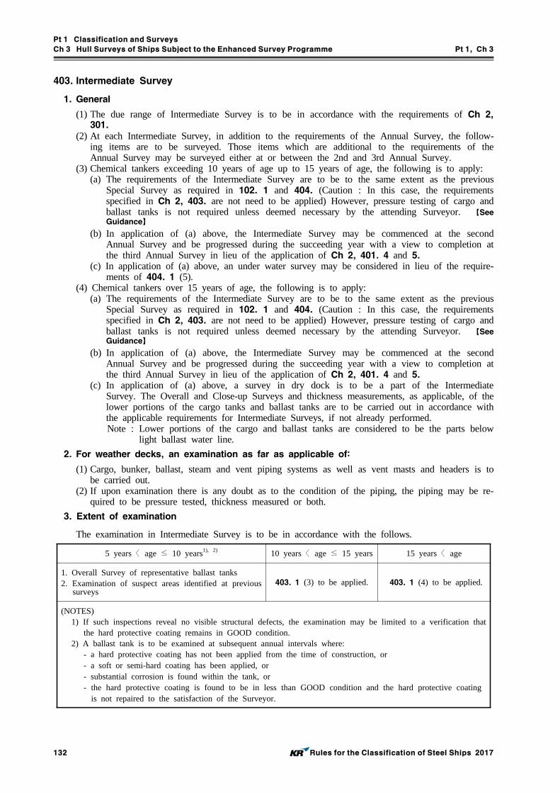
Pt 1 Classification and Surveys
Ch 3 Hull Surveys of Ships Subject to the Enhanced Survey Programme Pt 1, Ch 3
132 Rules for the Classification of Steel Ships 2017
403. Intermediate Survey
1. General
(1) The due range of Intermediate Survey is to be in accordance with the requirements of Ch 2, 301.
(2) At each Intermediate Survey, in addition to the requirements of the Annual Survey, the follow-ing items are to be surveyed. Those items which are additional to the requirements of the Annual Survey may be surveyed either at or between the 2nd and 3rd Annual Survey.
(3) Chemical tankers exceeding 10 years of age up to 15 years of age, the following is to apply:(a) The requirements of the Intermediate Survey are to be to the same extent as the previous
Special Survey as required in 102. 1 and 404. (Caution : In this case, the requirements specified in Ch 2, 403. are not need to be applied) However, pressure testing of cargo and ballast tanks is not required unless deemed necessary by the attending Surveyor. 【See Guidance】
(b) In application of (a) above, the Intermediate Survey may be commenced at the second Annual Survey and be progressed during the succeeding year with a view to completion at the third Annual Survey in lieu of the application of Ch 2, 401. 4 and 5.
(c) In application of (a) above, an under water survey may be considered in lieu of the require-ments of 404. 1 (5).
(4) Chemical tankers over 15 years of age, the following is to apply:(a) The requirements of the Intermediate Survey are to be to the same extent as the previous
Special Survey as required in 102. 1 and 404. (Caution : In this case, the requirements specified in Ch 2, 403. are not need to be applied) However, pressure testing of cargo and ballast tanks is not required unless deemed necessary by the attending Surveyor. 【See Guidance】
(b) In application of (a) above, the Intermediate Survey may be commenced at the second Annual Survey and be progressed during the succeeding year with a view to completion at the third Annual Survey in lieu of the application of Ch 2, 401. 4 and 5.
(c) In application of (a) above, a survey in dry dock is to be a part of the Intermediate Survey. The Overall and Close-up Surveys and thickness measurements, as applicable, of the lower portions of the cargo tanks and ballast tanks are to be carried out in accordance with the applicable requirements for Intermediate Surveys, if not already performed.Note : Lower portions of the cargo and ballast tanks are considered to be the parts below
light ballast water line.
2. For weather decks, an examination as far as applicable of:
(1) Cargo, bunker, ballast, steam and vent piping systems as well as vent masts and headers is to be carried out.
(2) If upon examination there is any doubt as to the condition of the piping, the piping may be re-quired to be pressure tested, thickness measured or both.
3. Extent of examination
The examination in Intermediate Survey is to be in accordance with the follows.
5 years〈 age ≤ 10 years1), 2) 10 years〈 age ≤ 15 years 15 years〈 age
1. Overall Survey of representative ballast tanks2. Examination of suspect areas identified at previous
surveys403. 1 (3) to be applied. 403. 1 (4) to be applied.
(NOTES)1) If such inspections reveal no visible structural defects, the examination may be limited to a verification that
the hard protective coating remains in GOOD condition.2) A ballast tank is to be examined at subsequent annual intervals where:
- a hard protective coating has not been applied from the time of construction, or- a soft or semi-hard coating has been applied, or- substantial corrosion is found within the tank, or- the hard protective coating is found to be in less than GOOD condition and the hard protective coating
is not repaired to the satisfaction of the Surveyor.
Pt 1 Classification and Surveys
Ch 3 Hull Surveys of Ships Subject to the Enhanced Survey Programme Pt 1, Ch 3
Rules for the Classification of Steel Ships 2017 133
404. Special Survey
1. General
(1) The due range of Special Survey is to be in accordance with the requirements of Ch 2, 401.(2) The Special Survey is to include, in addition to the requirements of the Annual Survey, exami-
nation, tests and checks of sufficient extent to ensure that the hull and related piping, as re-quired in (4), is in a satisfactory condition and is fit for its intended purpose for the new peri-od of class of 5 years to be assigned, subject to proper maintenance and operation and to peri-odical surveys being carried out at the due dates.
(3) All cargo tanks, ballast tanks, including double bottom tanks, pump rooms, pipe tunnels, coffer-dams and void spaces bounding cargo tanks, decks and outer hull are to be examined, this ex-amination is to be supplemented by thickness measurement and testing as required in Par 4 and Par 5, to ensure that the structural integrity remains effective. The aim of the examination is to discover substantial corrosion, significant deformation, fractures, damages or other structural dete-rioration, that may be present.
(4) Cargo piping on deck and cargo and ballast piping within the tanks and spaces specified in (3) above are to be examined and operationally tested to working pressure to attending Surveyor's satisfaction to ensure that tightness and condition remain satisfactory. Special attention is to be given to any ballast piping in cargo tanks and cargo piping in ballast tanks and void spaces, and Surveyors are to be advised on all occasions when this piping, including valves and fittings are opened during repair periods and can be examined internally. 【See Guidance】
(5) A survey in dry dock is to be a part of the Special Survey. The Overall and Close-up Surveys and thickness measurements, as applicable, of the lower portions of the cargo tanks and ballast tanks are to be carried out in accordance with the applicable requirements for Special Surveys, if not already performed.Note : Lower portions of the cargo and ballast tanks are considered to be the parts below light
ballast water line.
2. Tank protection
Where provided, the condition of the corrosion prevention system of cargo tanks is to be examined. A ballast tank is to be examined at subsequent annual intervals where: - a hard protective coating has not been applied from the time of construction, or - a soft or semi-hard coating has been applied, or - substantial corrosion is found within the tank, or - the hard protective coating is found to be in less than GOOD condition and the hard protective
coating is not repaired to the satisfaction of the Surveyor. Thickness measurements are to be carried out as deemed necessary by the Surveyor. 【See Guidance】
3. Extent of Overall and Close-up Survey
(1) An Overall Survey of all tanks and spaces specified in 401. 1 (2) (a) and (b) is to be carried out at each Special Survey.
(2) The minimum requirements for Close-up Survey at Special Survey are given in Table 1.3.7. The survey of stainless steel tanks may be carried out as an Overall Survey supplemented by Close-up Survey as deemed necessary by the Surveyor. 【See Guidance】
(3) The Surveyor may extend the Close-up Survey as deemed necessary taking into account the maintenance of the tanks under survey, the condition of the corrosion prevention system and al-so in the following cases:(a) In particular, tanks having structural arrangements or details which have suffered defects in
similar tanks or on similar ships according to available information.(b) In tanks which have structures approved with reduced scantlings due to an approved corro-
sion control system.(4) For areas in tanks where hard protective coatings are found to be in GOOD condition, the ex-
tent of Close-up Surveys according to Table 1.3.7 may be specially considered.

Pt 1 Classification and Surveys
Ch 3 Hull Surveys of Ships Subject to the Enhanced Survey Programme Pt 1, Ch 3
134 Rules for the Classification of Steel Ships 2017
4. Extent of Thickness Measurement
(1) The minimum requirements for thickness measurements at Special Survey are given in Table 1.3.8. The thickness measurement of stainless steel hull structure and piping may be waived, except for clad steel plating.
(2) Provisions for extended measurements for areas with substantial corrosion are given in the Guidance relating to the Rules, and as may be additionally specified in the survey programme as required in 102. 1. These extended thickness measurements are to be carried out before the survey is credited as completed. Suspect areas identified at previous surveys are to be examined. Areas of substantial corrosion identified at previous surveys are to have thickness measurements taken. 【See Guidance】
(3) The Surveyor may further extend the thickness measurements as deemed necessary. 【See Guidance】
(4) For areas in tanks where hard protective coatings are found to be in a GOOD condition, the extent of thickness measurements according to Table 1.3.8 may be specially considered.
(5) Transverse sections are to be chosen where the largest reductions are suspected to occur or are revealed from deck plating measurements.
(6) In case where two or three sections are to be measured, at least one is to include a ballast tank within 0.5 amidships.
5. Extent of tank testing 【See Guidance】
(1) The minimum requirements for tank testing at Special Survey are given in Table 1.3.9.(2) Cargo tank testing carried out by the vessel's crew under the direction of the Master may be
accepted by the Surveyor provided the following conditions are complied with:(A) a tank testing procedure, specifying fill heights, tanks being filled and bulkheads being test-
ed, etc. has been submitted by the Owner and reviewed by the Society prior to the testing being carried out.
(B) there is no record of leakage, distortion or substantial corrosion that would affect the struc-tural integrity of the tank.
(C) the tank testing has been satisfactorily carried out within Special Survey window not more than 3 months prior to the date of the survey on which the Overall or Close-up Survey is completed.
(D) the satisfactory results of the testing is recorded in the vessel's logbook.(E) the internal and external condition of the tanks and associated structure are found sat-
isfactory by the Surveyor at the time of the Overall and Close-up Survey.
6. Chemical tankers over 10 years of age
(1) Selected steel cargo pipes outside cargo tanks and ballast pipes passing through cargo tanks are to be:(a) thickness measured at random or selected pipe lengths to be opened for internal inspection.(b) pressure tested to the maximum working pressure.
(2) Special attention is to be given to cargo/slop discharge piping through ballast tanks and void spaces.

Pt 1 Classification and Surveys
Ch 3 Hull Surveys of Ships Subject to the Enhanced Survey Programme Pt 1, Ch 3
Rules for the Classification of Steel Ships 2017 135
Table 1.3.7 Minimum requirements for Close-up Survey at Special Survey of Chemical Tankers1) 【See Guidance】
1) Single Skin Chemical Tankers
Special SurveyNo. 1
Special SurveyNo. 2
Special SurveyNo. 3
Special Survey No. 4and Subsequent
1. One web frame ring in a ballast wing
tank (A)
2. One deck transverse in a cargo tank or
on deck (B)
3. One transverse bulk-head lower part in a
ballast tank (D)
4. One transverse bulk-head lower part in a cargo wing tank
(D)
5. One transverse bulk-head lower part in a cargo centre tank2)
(D)
1. All web frame rings in a ballast wing tank or double
bottom ballast tank (A)
2. One deck transverse in each remaining ballast tank
or on deck (B)
3. One deck transverse in a cargo wing tank or on
deck (B)
4. One deck transverse in two cargo centre tanks or on
deck (B)
5. Both transverse bulkhead in
a ballast wing tank (C)
6. One transverse bulkhead lower part in each remain-
ing ballast tank (D)
7. One transverse bulkhead lower part in two cargo
centre tanks2) (D)
8. One transverse bulkhead lower part in a cargo wing
tank (D)
1. All web frame rings in
all ballast tanks (A)
2. All web frame rings in a cargo wing tank
(A)
3. One web frame ring in each remaining cargo
tank (A)
4. All transverse bulk-heads in all cargo
tanks (C)
5. All transverse bulk-heads in all ballast
tanks (C)
1. All web frame rings in
all ballast tanks (A)
2. All web frame rings in a cargo wing tank
(A)
3. One web frame ring in each remaining cargo
tank (A)
4. All transverse bulk-heads in all cargo
tanks (C)
5. All transverse bulk-heads in all ballast
tanks (C)
6. Additional transverse areas as deemed neces-sary by the Society
(NOTES)
1) (A) to (D) mean as follows and are illustrated in Annex 1-6 of the Guidance: 【See Guidance】
(A) : Complete transverse web frame ring including adjacent structural members(B) : Deck transverse including adjacent deck structural members(C) : Transverse bulkhead complete including girder system and adjacent structural members(D) : Transverse bulkhead lower part including girder system and adjacent structural members
2) Where no centre cargo tanks are fitted(as in the case of centre longitudinal bulkhead), transverse bulk-heads in wing tanks are to be surveyed.

Pt 1 Classification and Surveys
Ch 3 Hull Surveys of Ships Subject to the Enhanced Survey Programme Pt 1, Ch 3
136 Rules for the Classification of Steel Ships 2017
Table 1.3.7 Minimum requirements for Close-up Survey at Special Survey of Chemical Tankers1) (continued) 【See Guidance】
2) Double Skin Chemical Tankers
Special SurveyNo. 1
Special SurveyNo. 2
Special SurveyNo. 3
Special Survey No. 4and Subsequent
1. One web frame ring in a ballast double
hull tank2) (1)
2. One deck transverse in a cargo tank or
on deck (2)
3. One transverse bulk-head in a ballast
tank2) (4)
4. One transverse bulk-head in a cargo
wing tank (5)
5. One transverse bulk-head in a cargo cen-
tre tank3) (5)
1. All web frame rings in a ballast wing tank or ballast
double hull tank2) (1)
2. The knuckle area and the upper part(3 metres approx) of one web frame in each
remaining ballast tank (6)
3. One deck transverse in two
cargo tanks (2)
4. One transverse bulkhead in
each ballast tank2) (4)
5. One transverse bulkhead in
two cargo centre tanks3) (5)
6. One transverse bulkhead in
a cargo wing tank (5)
1. All web frame rings in
all ballast tanks (1)
2. All web frame rings in
a cargo wing tank (7)
3. One web frame ring in each remaining cargo
tank (7)
4. All transverse bulk-heads in all cargo
tanks (3)
5. All transverse bulk-heads in all ballast
tanks (4)
1. All web frame rings in
all ballast tanks (1)
2. All web frame rings in
a cargo wing tank (7)
3. One web frame ring in each remaining cargo
tank (7)
4. All transverse bulk-heads in all cargo
tanks (3)
5. All transverse bulk-heads in all ballast
tanks (4)
6. Additional transverse areas as deemed neces-sary by the Society
(NOTES)1) (*1) to (*7) mean as follows and are illustrated in Annex 1-6 of the Guidance:
(*1) Web frame in a ballast tank means vertical web in side tank, hopper web in hopper tank, floor in double bottom tank and deck transverse in double deck tank(where fitted), including adjacent structural members. In fore and aft peak tanks web frame means a complete transverse web frame ring including adjacent structural members.
(*2) Deck transverse, including adjacent deck structural members(or external structure on deck in way of the tank, where applicable)
(*3) Transverse bulkhead complete in cargo tanks, including girder system, adjacent structural mem-bers(such as longitudinal bulkheads) and internal structure of lower and upper stools, where fitted.
(*4) Transverse bulkhead complete in ballast tanks, including girder system and adjacent structural members, such as longitudinal bulkheads, girders in double bottom tanks, inner bottom plating, hopper side, connecting brackets.
(*5) Transverse bulkhead lower part in cargo tank, including girder system, adjacent structural mem-bers(such as longitudinal bulkheads) and internal structure of lower stool, where fitted.
(*6) The knuckle area and the upper part(3 metres approximately), including adjacent structural members. Knuckle area is the area of the web frame around the connections of the slope hopper plating to the inner hull bulkhead and the inner bottom plating, up to 2 metres from the corners both on the bulkhead and the double bottom.
(*7) Web frame in a cargo oil tank means deck transverse, longitudinal bulkhead structural elements and cross ties, where fitted, including adjacent structural members.
2) Ballast double hull tank means double bottom tank plus double side tank plus double deck tank, as ap-plicable, even if these tanks are separate.
3) Where no centre cargo tanks are fitted(as in the case of centre longitudinal bulkhead), transverse bulk-heads in wing tanks are to be surveyed.

Pt 1 Classification and Surveys
Ch 3 Hull Surveys of Ships Subject to the Enhanced Survey Programme Pt 1, Ch 3
Rules for the Classification of Steel Ships 2017 137
Table 1.3.8 Minimum requirements for thickness measurements at Special Survey of Chemical Tankers
Special SurveyNo. 1
Special SurveyNo. 2
Special SurveyNo. 3
Special Survey No. 4and Subsequent
1. Suspect areas
2. One transverse section of deck plating for the full beam of the ship within the cargo area (in way of a ballast tank, if any, or a cargo tank used primarily for water ballast)
3. Measurements, for gen-eral assessment and re-cording of corrosion pattern, of those struc-tural members subject to Close-up Survey ac-cording to Table 1.3.7 1) or 2), as applicable
1. Suspect areas
2. Within the cargo area:1) Each deck plate2) One transverse section
3. Measurements, for gen-eral assessment and re-cording of corrosion pattern, of those struc-tural members subject to Close-up Survey ac-cording to Table 1.3.7 1) or 2), as applicable
4. Selected wind and wa-ter strakes outside the cargo area
1. Suspect areas
2. Within the cargo area:1) Each deck plate2) Two transverse sections1)
3) All wind and water
strakes
3. Measurements, for gen-eral assessment and re-cording of corrosion pattern, of those struc-tural members subject to Close-up Survey ac-cording to Table 1.3.7 1) or 2), as applicable
4. Selected wind and wa-ter strakes outside the cargo area
1. Suspect areas
2. Within the cargo area:1) Each deck plate2) Three transverse sections1)
3) Each bottom plate
3. Measurements, for gen-eral assessment and re-cording of corrosion pattern, of those struc-tural members subject to Close-up Survey ac-cording to Table 1.3.7 1) or 2), as applicable
4. All wind and water strakes, full length
(NOTES)1) At least one section is to include a ballast tank within 0.5 amidships.
Table 1.3.9 Minimum requirements for tank testing at Special Survey of Chemical Tankers
Special Survey No. 1 Special Survey No. 2 and Subsequent
1. All ballast tank boundaries
2. Cargo tank boundaries facing ballast tanks, void spaces, pipe tunnels, pump-rooms or cofferdams
1. All ballast tank boundaries
2. All cargo tank bulkheads
(NOTES)1. The Surveyor may extend the tank testing as deemed necessary. 【See Guidance】
2. Boundaries of ballast tanks are to be tested with a head of liquid to the top of air pipes.3. Boundaries of cargo tanks are to be tested to the highest point that liquid will rise under service
conditions.
4. The testing of double bottom and other spaces not designed for the carriage of liquid may be omitted, pro-
vided a satisfactory internal examination together with an examination of the tanktop is carried out.

Pt 1 Classification and Surveys
Ch 3 Hull Surveys of Ships Subject to the Enhanced Survey Programme Pt 1, Ch 3
138 Rules for the Classification of Steel Ships 2017
Section 5 Double Hull Oil Tankers
501. General
1. Application
(1) In addition to the requirements specified in Ch 2, the requirements apply to surveys of hull structure and piping systems in way of the following spaces for all double hull oil tankers with ESP notation.(a) cargo tanks, pump rooms, cofferdams, pipe tunnels, void spaces within the cargo area(b) all ballast tanks
(2) The requirements contain the minimum extent of examination, thickness measurements and tank testing. The survey is to be extended when substantial corrosion and/or structural defects are found and include additional Close-up Survey when necessary. 【See Guidance】
2. Definitions
(1) A double hull oil tanker is a ship which is constructed primarily for the carriage of oil in bulk, which have the cargo tanks protected by a double hull which extends for the entire length of the cargo area, consisting of double sides and double bottom spaces for the carriage of water ballast or void spaces.
(2) A transverse section includes all longitudinal members such as plating, longitudinals and gird-ers at the deck, sides, bottom, inner bottom and longitudinal bulkheads. For transversely framed vessels, a transverse section includes adjacent frames and their end connections in way of trans-verse sections.
(3) Cargo area is that part of the ship which contains cargo tanks, slop tanks and car-go/ballast pump rooms, cofferdams, ballast tanks and void spaces adjacent to cargo tanks and also deck areas throughout the entire length and breadth of the part of the ship over above mentioned spaces.
(4) A ballast tank is a tank which is used solely for the carriage of salt water ballast.(5) A combined cargo/ballast tank is a tank which is used for the carriage of cargo or ballast
water as a routine part of the vessel's operation and will be treated as a ballast tank. Cargo tanks in which water ballast might be carried only in exceptional cases per MARPOL Annex I, Ch 4, Reg. 18.3 are to be treated as cargo tanks.

Pt 1 Classification and Surveys
Ch 3 Hull Surveys of Ships Subject to the Enhanced Survey Programme Pt 1, Ch 3
Rules for the Classification of Steel Ships 2017 139
502. Annual Survey
1. General
(1) The due range of Annual Survey is to be in accordance with the requirements of Ch 2, 201.(2) The survey is to consist of an examination for the purpose of ensuring, as far as practicable,
that the hull and piping are maintained in a satisfactory condition.
2. Examination of the hull
(1) Examination of the hull plating and its closing appliances as far as can be seen.(2) Examination of watertight penetrations as far as practicable.
3. Examination of the weather deck
(1) Examination of cargo tank openings including gaskets, covers, coamings and flame screens.(2) Examination of cargo tanks pressure/vacuum valves and flame screens.(3) Examination of flame screens on the open ends of air pipes to all bunker tanks.(4) Examination of cargo, crude oil washing, bunker and vent piping systems, including vent masts
and headers.
4. Examination of cargo pump rooms and pipe tunnels(if fitted)
(1) Examination of all pump rooms bulkheads for signs of oil leakage or fractures and, in partic-ular, the sealing arrangements of all penetrations of pump room bulkheads.
(2) Examination of the condition of all piping systems.
5. Examination of ballast tanks
Examination of ballast tanks where required as a consequence of the results of the Special Survey(See 504. 2) and Intermediate Survey(See 503. 3) is to be carried out. When considered necessary by the Surveyor, or when extensive corrosion exists, thickness measurements are to be carried out and if the results of these thickness measurements indicate that substantial corrosion is found, the extent of thickness measurements is to be increased in accordance with the Guidance re-lating to the Rules. These extended thickness measurements are to be carried out before the survey is credited as completed. Suspect areas identified at previous surveys are to be examined. Areas of substantial corrosion identified at previous surveys are to have thickness measurements taken. 【See Guidance】
6. For vessels built under IACS Common Structural Rules(Pt 12 or Pt 13), the identified substantial corrosion areas are to be examined and additional thickness measurements are to be carried out.

Pt 1 Classification and Surveys
Ch 3 Hull Surveys of Ships Subject to the Enhanced Survey Programme Pt 1, Ch 3
140 Rules for the Classification of Steel Ships 2017
503. Intermediate Survey
1. General
(1) The due range of Intermediate Survey is to be in accordance with the requirements of Ch 2, 301.(2) At each Intermediate Survey, in addition to the requirements of the Annual Survey, the follow-
ing items are to be surveyed. Those items which are additional to the requirements of the Annual Survey may be surveyed either at or between the 2nd and 3rd Annual Survey.
(3) Double hull oil tankers exceeding 10 years of age up to 15 years of age, the following is to apply:(a) The requirements of the Intermediate Survey are to be to the same extent as the previous
Special Survey as required in 102. 1 and 504. (Caution : In this case, the requirements specified in Ch 2, 403. are not need to be applied) However, pressure testing of cargo and ballast tanks and the requirements for longitudinal strength evaluation of hull girder as re-quired in 105. 1 (2) are not required unless deemed necessary by the attending Surveyor. 【See Guidance】
(b) In application of (a) above, the Intermediate Survey may be commenced at the second Annual Survey and be progressed during the succeeding year with a view to completion at the third Annual Survey in lieu of the application of Ch 2, 401. 4 and 5.
(c) In application of (a) above, an under water survey may be considered in lieu of the require-ments of 504. 1 (5).
(4) Double hull oil tankers over 15 years of age, the following is to apply:(a) The requirements of the Intermediate Survey are to be to the same extent as the previous
Special Survey as required in 102. 1 and 504. (Caution : In this case, the requirements specified in Ch 2, 403. are not need to be applied) However, pressure testing of cargo and ballast tanks and the requirements for longitudinal strength evaluation of hull girder as re-quired in 105. 1 (2) are not required unless deemed necessary by the attending Surveyor. 【See Guidance】
(b) In application of (a) above, the Intermediate Survey may be commenced at the second Annual Survey and be progressed during the succeeding year with a view to completion at the third Annual Survey in lieu of the application of Ch 2, 401. 4 and 5.
(c) In application of (a) above, a survey in dry dock is to be a part of the Intermediate Survey. The Overall and Close-up Surveys and thickness measurements, as applicable, of the lower portions of the cargo tanks and ballast tanks are to be carried out in accordance with the applicable requirements for Intermediate Surveys, if not already performed.Note : Lower portions of the cargo and ballast tanks are considered to be the parts below
light ballast water line.(5) For vessels built under IACS Common Structural Rules(Pt 12 or Pt 13), the identified substantial
corrosion areas are to be examined and additional thickness measurements are to be carried out.
2. For weather decks, an examination as far as applicable of:
(1) Cargo, crude oil washing, bunker, ballast, steam and vent piping systems as well as vent masts and headers is to be carried out.
(2) If upon examination there is any doubt as to the condition of the piping, the piping may be re-quired to be pressures-tested, thickness measured or both.
3. Extent of examination
The examination in Intermediate Survey is to be in accordance with the follows.
5 years < age ≤ 10 years1), 2) 10 years < age ≤ 15 years 15 years < age
1. Overall Survey of representative ballast tanks2. Examination of suspect areas identified at previous
surveys503. 1 (3) to be applied. 503. 1 (4) to be applied.
(NOTES)1) If such inspections reveal no visible structural defects, the examination may be limited to a verification
that the hard protective coating remains in GOOD condition.2) A ballast tank is to be examined at subsequent annual intervals where:
- a hard protective coating has not been applied from the time of construction, or- a soft or semi-hard coating has been applied, or- substantial corrosion is found within the tank, or- the hard protective coating is found to be in less than GOOD condition and the hard protective coat-
ing is not repaired to the satisfaction of the Surveyor.

Pt 1 Classification and Surveys
Ch 3 Hull Surveys of Ships Subject to the Enhanced Survey Programme Pt 1, Ch 3
Rules for the Classification of Steel Ships 2017 141
504. Special Survey
1. General
(1) The due range of Special Survey is to be in accordance with the requirements of Ch 2, 401.(2) The Special Survey is to include, in addition to the requirements of the Annual Survey, exami-
nation, tests and checks of sufficient extent to ensure that the hull and related piping, as re-quired in (4), is in a satisfactory condition and is fit for its intended purpose for the new peri-od of class of 5 years to be assigned, subject to proper maintenance and operation and to peri-odical surveys being carried out at the due dates.
(3) All cargo tanks, ballast tanks, including double bottom tanks, pump rooms, pipe tunnels, coffer-dams and void spaces bounding cargo tanks, decks and outer hull are to be examined, this ex-amination is to be supplemented by thickness measurement and testing as required in Par 4 and Par 5, to ensure that the structural integrity remains effective. The aim of the examination is to discover substantial corrosion, significant deformation, fractures, damages or other structural dete-rioration, that may be present.
(4) Cargo piping on deck, including crude oil washing (COW) piping, cargo and ballast piping with-in the tanks and spaces specified in (3) above are to be examined and operationally tested to working pressure to attending Surveyor's satisfaction to ensure that tightness and condition re-main satisfactory. Special attention is to be given to any ballast piping in cargo tanks and cargo piping in ballast tanks and void spaces, and Surveyors are to be advised on all occasions when this piping, including valves and fittings are opened during repair periods and can be examined internally. 【See Guidance】
(5) A survey in dry dock is to be a part of the Special Survey. The Overall and Close-up Surveys and thickness measurements, as applicable, of the lower portions of the cargo tanks and ballast tanks are to be carried out in accordance with the applicable requirements for Special Surveys, if not already performed.Note : Lower portions of the cargo and ballast tanks are considered to be the parts below light
ballast water line.
2. Tank protection
Where provided, the condition of the corrosion prevention system of cargo tanks is to be examined. A ballast tank is to be examined at subsequent annual intervals where:
- a hard protective coating has not been applied from the time of construction, or- a soft or semi-hard coating has been applied, or- substantial corrosion is found within the tank, or- the hard protective coating is found to be in less than GOOD condition and the hard pro-
tective coating is not repaired to the satisfaction of the Surveyor.Thickness measurements are to be carried out as deemed necessary by the Surveyor. 【See Guidance】
3. Extent of Overall and Close-up Survey
(1) An Overall Survey of all tanks and spaces specified in 501. 1 (1) (a) and (b) is to be carried out at each Special Survey.
(2) The minimum requirements for Close-up Survey at Special Survey are given in Table 1.3.10.(3) The Surveyor may extend the Close-up Survey as deemed necessary taking into account the
maintenance of the tanks under survey, the condition of the corrosion prevention system and al-so in the following cases:(a) In particular, tanks having structural arrangements or details which have suffered defects in
similar tanks or on similar ships according to available information.(b) In tanks which have structures approved with reduced scantlings due to an approved corro-
sion control system.(4) For areas in tanks where hard protective coatings are found to be in GOOD condition, the ex-
tent of Close-up Surveys according Table 1.3.10 may be specially considered.
Pt 1 Classification and Surveys
Ch 3 Hull Surveys of Ships Subject to the Enhanced Survey Programme Pt 1, Ch 3
142 Rules for the Classification of Steel Ships 2017
4. Extent of thickness measurement
(1) The minimum requirements for thickness measurements at Special Survey are given in Table 1.3.11.
(2) Provisions for extended measurements for areas with substantial corrosion are given in the Guidance relating to the Rules, and as may be additionally specified in the survey programme as required in 102. 1. These extended thickness measurements are to be carried out before the survey is credited as completed. Suspect areas identified at previous surveys are to be examined. Areas of substantial corrosion identified at previous surveys are to have thickness measurements taken. For vessels built under IACS Common Structural Rules(Pt 12 or Pt 13), the identified substantial corrosion areas are required to be examined and additional thickness measurements are to be carried out at Annual and Intermediate Surveys. 【See Guidance】
(3) The Surveyor may further extend the thickness measurements as deemed necessary. 【See Guidance】
(4) For areas in tanks where hard protective coatings are found to be in GOOD condition, the ex-tent of thickness measurements according to Table 1.3.11 may be specially considered.
(5) Transverse sections are to be chosen where the largest reductions are suspected to occur or are revealed from deck plating measurements.
(6) In case where two or three sections are to be measured, at least one is to include a ballast tank within 0.5 amidships. In case of oil tankers of 130 m in length and upwards(i.e. length for freeboard() as defined in Pt 3, Ch 1, 103.) and more than 10 years of age, for the eval-uation of the ship's longitudinal strength as required in 106. 1 (2), the sampling method of thickness measurements is given in the Guidance relating to the Rules. 【See Guidance】
In case of ships built under IACS Common Structural Rules for Bulk Carriers and Oil Tankers(Pt 13), for the evaluation of the ship's longitudinal strength as required in 106. 1 (4), the sampling method of thickness measurements is given in the Guidance relating to the Rules.
5. Extent of tank testing 【See Guidance】
(1) The minimum requirements for tank testing at Special Survey are given in Table 1.3.12.(2) Cargo tank testing carried out by the vessel's crew under the direction of the Master may be
accepted by the Surveyor provided the following conditions are complied with:(A) a tank testing procedure, specifying fill heights, tanks being filled and bulkheads being test-
ed, etc. has been submitted by the Owner and reviewed by the Society prior to the testing being carried out.
(B) there is no record of leakage, distortion or substantial corrosion that would affect the struc-tural integrity of the tank.
(C) the tank testing has been satisfactorily carried out within Special Survey window not more than 3 months prior to the date of the survey on which the Overall or Close-up Survey is completed.
(D) the satisfactory results of the testing is recorded in the vessel's logbook.(E) the internal and external condition of the tanks and associated structure are found sat-
isfactory by the Surveyor at the time of the Overall and Close-up Survey.

Pt 1 Classification and Surveys
Ch 3 Hull Surveys of Ships Subject to the Enhanced Survey Programme Pt 1, Ch 3
Rules for the Classification of Steel Ships 2017 143
Special SurveyNo. 1
Special SurveyNo. 2
Special SurveyNo. 3
Special Survey No. 4and Subsequent
1. One web frame, in a bal-last tank2) (*1)
2. One deck transverse, in a cargo oil tank (*2)
3. One transverse bulkhead, in a ballast tank2) (*4)
4. One transverse bulkhead, in a cargo oil centre tank3) (*5)
5. One transverse bulkhead, in a cargo oil wing tank (*5)
1. All web frames, in a bal-last tank2) (*1)
2. The knuckle area and the upper part (5 meters ap-proximately) of one web frame in each remaining ballast tank (*6)
3. One deck transverse, in two cargo oil tanks (*2)
4. One transverse bulkhead, in each ballast tank2) (*4)
5. One transverse bulkhead, in two cargo oil centre tanks3) (*5)
6. One transverse bulkhead, in a cargo oil wing tank (*5)
1. All web frames, in all ballast tanks (*1)
2. All web frames, including deck transverse and cross ties, if fitted, in a cargo oil tank (*7)
3. One web frame, including deck transverse and cross ties, if fitted, in each re-maining cargo oil tank (*7)
4. All transverse bulkheads, in all cargo oil (*3) and ballast (*4) tanks
1. As for Special Survey No. 3
2. Additional transverse areas as deemed neces-sary by the Society
(NOTES)1) (*1) to (*7) mean as follows and are illustrated in Annex 1-6 of the Guidance: 【See Guidance】
(*1) Web frame in a ballast tank means vertical web in side tank, hopper web in hopper tank, floor in double bottom tank and deck transverse in double deck tank(where fitted), including adjacent struc-tural members. In fore and aft peak tanks web frame means a complete transverse web frame ring including adjacent structural members.
(*2) Deck transverse, including adjacent deck structural members(or external structure on deck in way of the tank, where applicable)
(*3) Transverse bulkhead complete in cargo tanks, including girder system, adjacent structural mem-bers(such as longitudinal bulkheads) and internal structure of lower and upper stools, where fitted.
(*4) Transverse bulkhead complete in ballast tanks, including girder system and adjacent structural mem-bers, such as longitudinal bulkheads, girders in double bottom tanks, inner bottom plating, hopper side, connecting brackets.
(*5) Transverse bulkhead lower part in cargo tank, including girder system, adjacent structural mem-bers(such as longitudinal bulkheads) and internal structure of lower stool, where fitted.
(*6) The knuckle area and the upper part(5 metres approximately), including adjacent structural members. Knuckle area is the area of the web frame around the connections of the slope hopper plating to the inner hull bulkhead and the inner bottom plating, up to 2 metres from the corners both on the bulk-head and the double bottom.
(*7) Web frame in a cargo oil tank means deck transverse, longitudinal bulkhead structural elements and cross ties, where fitted, including adjacent structural members.
2) Ballast tank : means double bottom tank plus double side tank plus double deck tank, as applicable, even if these tanks are separate.
3) Where no centre cargo tanks are fitted(as in the case of centre longitudinal bulkhead), transverse bulkheads in wing tanks are to be surveyed.
Table 1.3.10 Minimum requirements for Close-up Survey at Special Survey of Double Hull Oil Tankers
1) 【See Guidance】

Pt 1 Classification and Surveys
Ch 3 Hull Surveys of Ships Subject to the Enhanced Survey Programme Pt 1, Ch 3
144 Rules for the Classification of Steel Ships 2017
Table 1.3.11 Minimum requirements for thickness measurements at Special Survey of Double Hull Oil Tankers
Special SurveyNo. 1
Special SurveyNo. 2
Special SurveyNo. 3
Special Survey No. 4and Subsequent
1. Suspect areas
2. One section of deck plat-ing for the full beam of the ship within the cargo area
3. Measurements, for general assessment and recording of corrosion pattern, of those structural members subject to Close-up Survey according to Table 1.3.10
1. Suspect areas
2. Within the cargo area :1) Each deck plate2) One transverse section
3. Measurements, for general assessment and recording of corrosion pattern, of those structural members subject to Close-up Survey according to Table 1.3.10
4. Selected wind and water strakes outside the cargo area
1. Suspect areas
2. Within the cargo area:1) Each deck plate2) Two transverse sections1)
3) All wind and water strakes
3. Measurements, for general assessment and recording of corrosion pattern, of those structural members subject to Close-up Survey according to Table 1.3.10
4. Selected wind and water strakes outside the cargo area
1. Suspect areas
2. Within the cargo area:1) Each deck plate2) Three transverse sections1)
3) Each bottom plate
3. Measurements, for general assessment and recording of corrosion pattern, of those structural members subject to Close-up Survey according to Table 1.3.10
4. All wind and water strakes, full length
(NOTES)1) At least one section is to include a ballast tank within 0.5 amidships.
Table 1.3.12 Minimum requirements for tank testing at Special Survey of Double Hull Oil Tankers
Special Survey No. 1 Special Survey No. 2 and Subsequent
1. All ballast tank boundaries
2. Cargo tank boundaries facing ballast tanks, void spaces, pipe tunnels, pump-rooms or cofferdams
1. All ballast tank boundaries
2. All cargo tank bulkheads
(NOTES)1. The Surveyor may extend the tank testing as deemed necessary. 【See Guidance】
2. Boundaries of ballast tanks are to be tested with a head of liquid to the top of air pipes.3. Boundaries of cargo tanks are to be tested to the highest point that liquid will rise under service conditions.
4. The testing of double bottom and other spaces not designed for the carriage of liquid may be omitted, pro-
vided a satisfactory internal examination together with an examination of the tanktop is carried out.

Pt 1 Classification and Surveys
Ch 3 Hull Surveys of Ships Subject to the Enhanced Survey Programme Pt 1, Ch 3
Rules for the Classification of Steel Ships 2017 145
Section 6 Double Skin Bulk Carriers
601. General
1. Application
(1) In addition to the requirements specified in Ch 2, the requirements apply to surveys of hull structure and piping systems in way of the following spaces for all double skin bulk carriers with ESP notation.(A) cargo holds, cofferdams, pipe tunnels, void spaces, fuel oil tanks within the cargo length
area(B) all ballast tanks
(2) The requirements contain the minimum extent of examination, thickness measurements and tank testing. The survey is to be extended when Substantial Corrosion and/or structural defects are found and include additional Close-up Survey when necessary. 【See Guidance】
(3) For some cargo holds of single side skin, and where IACS UR S19 or S30 is required to be complied, the requirements of Sec 2 are to apply as applicable.
2. Definitions
(1) A Double Skin Bulk Carrier is a ship which is constructed generally with single deck, double bottom, topside tank and hopper side tanks in cargo spaces, and is intended primarily to carry dry cargo in bulk, including such types as ore carriers and combination carriers, in which all cargo holds are bounded by a double-side skin(regardless of the width of the wing space). For combination carriers with longitudinal bulkheads additional requirements are specified in Sec 3 or Sec 5, as applicable. Ore and combination carriers are not covered by the IACS Common Structural Rules for Bulk Carriers(Pt 11).
The following ships are not covered by the IACS Common Structural Rules for Bulk Carriers and Oil Tankers(Pt 13).
- Ore carriers- Combination carriers- Wood chip carriers- Cement, fly ash and sugar carriers provided that loading and unloading is not carried out
by grabs heavier than 10 tons, power shovels and other means which may damage car-go hold structure
- Ships with inner bottom construction adapted for self-unloading(2) A Ballast Tank is a tank which is used solely for salt water ballast, or, where applicable, a
space which is used for both cargo and salt water ballast will be treated as a ballast tank when substantial corrosion has been found in that space. A Double Side Tank is to be considered as a separate tank even if it is in connection to either the topside tank or the hopper side tank.
(3) A transverse section includes all longitudinal members such as plating, longitudinals and gird-ers at the deck, sides, bottom, inner bottom, hopper sides top wing inner sides and longitudinal bulkheads. For transversely framed vessels, a transverse section includes adjacent frames and their end connections in way of transverse sections.
(4) Spaces are separate compartments including holds, tanks, cofferdams and void spaces bounding cargo holds, decks and the outer hull.

Pt 1 Classification and Surveys
Ch 3 Hull Surveys of Ships Subject to the Enhanced Survey Programme Pt 1, Ch 3
146 Rules for the Classification of Steel Ships 2017
602. Annual Survey
1. General
(1) The due range of Annual Survey is to be in accordance with the requirements of Ch 2, 201.(2) The survey is to consist of an examination for the purpose of ensuring, as far as practicable,
that the hull, weather decks, hatch covers, coamings and piping are maintained in a satisfactory condition.
2. Examination of the hull
(1) Examination of the hull plating and its closing appliances as far as can be seen.(2) Examination of watertight penetrations as far as practicable.
3. Examination of weather deck, hatch covers and coamings
(1) Confirmation is to be obtained that no unapproved changes have been made to the hatch covers, hatch coamings and their securing and sealing devices since the last survey.
(2) A thorough survey of cargo hatch covers and coamings is only possible by examination in the open as well as closed positions and is to include verification of proper opening and closing operation. As a result, the hatch cover sets within the forward 25 % of the ship’s length and at least one additional set, such that all sets on the ship are assessed at least once in every 5-year period, are to be surveyed open, closed and in operation to the full extent on each direction at each Annual Survey, including:(A) stowage and securing in open condition(B) proper fit and efficiency of sealing in closed condition(C) operational testing of hydraulic and power components, wires, chains, and link drivesThe closing of the covers is to include the fastening of all peripheral and cross joint cleats or other securing devices. Particular attention is to be paid to the condition of the hatch covers in the forward 25% of the ship’s length, where sea loads are normally greatest.
(3) If there are indications of difficulty in operating and securing hatch covers, additional sets above those required by (2), at the discretion of the Surveyor, are to be tested in operation.
(4) Where the cargo hatch securing system does not function properly, repairs are to be carried out under the supervision of the Society.
(5) For each cargo hatch cover set, at each Annual Survey, the following items are to be surveyed:(A) cover panels, including side plates, and stiffener attachments that may be accessible in the
open position by Close-up Survey(for corrosion, cracks, deformation)(B) sealing arrangements of perimeter and cross joints(gaskets for condition and permanent de-
formation, flexible seals on combination carriers, gasket lips, compression bars, drainage channels and non return valves)
(C) clamping devices, retaining bars, cleating(for wastage, adjustment, and condition of rubber components)
(D) closed cover locating devices(for distortion and attachment)(E) chain or rope pulleys(F) guides(G) guide rails and track wheels(H) stoppers(I) wires, chains, tensioners, and gypsies(J) hydraulic system, electrical safety devices and interlocks(K) end and interpanel hinges, pins and stools where fitted
(6) At each hatchway, at each Annual Survey, the coamings, with panel stiffeners and brackets are to be checked for corrosion, cracks and deformation, especially of the coaming tops, including Close-up Survey.
(7) Where considered necessary, the effectiveness of sealing arrangements may be proved by hose or chalk testing supplemented by dimensional measurements of seal compressing components. 【See Guidance】

Pt 1 Classification and Surveys
Ch 3 Hull Surveys of Ships Subject to the Enhanced Survey Programme Pt 1, Ch 3
Rules for the Classification of Steel Ships 2017 147
(8) Where portable covers, wooden or steel pontoons are fitted, checking the satisfactory condition, where applicable, of:(A) wooden covers and portable beams, carriers or sockets for the portable beam, and their se-
curing devices(B) steel pontoons, including Close-up Survey of hatch cover plating(C) tarpaulins(D) cleats, battens and wedges(E) hatch securing bars and their securing devices(F) loading pads/bars and the side plate edge(G) guide plates and chocks(H) compression bars, drainage channels and drain pipes(if any)
(9) Examination of flame screens on the open ends of air pipes to all bunker tanks.(10) Examination of bunker and vent piping systems, including ventilators.
4. Examination of cargo holds 【See Guidance】
The examination of cargo holds in Annual Survey is to be in accordance with the follows.
10 years < age ≤ 15 years 15 years〈 age
Overall Survey Two selected cargo holds All cargo holds
OthersAll piping and penetrations in cargo
holds, including overboard piping, are to be examined.
All piping and penetrations in cargo holds, including overboard piping, are to
be examined.
(NOTES)1. When considered necessary by the Surveyor, or where extensive corrosion exists, thickness measurement
is to be carried out. If the results of these thickness measurements indicate that substantial corrosion is found, the extent of thickness measurements is to be increased in accordance with the Guidance relating to the Rules. These increased thickness measurements are to be carried out before the Annual Survey is credited as completed. Suspect areas identified at previous surveys are to be examined. Areas of sub-stantial corrosion identified at previous surveys are to have thickness measurements taken. For vessels built under the IACS Common Structural Rules(Pt 11 or Pt 13), the annual thickness gauging may be omitted where a hard protective coating has been applied in accordance with the coating manufacturer's requirements and is maintained in GOOD condition. 【See Guidance】
5. Examination of ballast tanks
Examination of ballast tanks when required as a consequence of the results of the Special Survey and Intermediate Survey is to be carried out. When considered necessary by the Surveyor, or where extensive corrosion exists, thickness measurements are to be carried out. If the results of these thickness measurements indicate that Substantial Corrosion is found, the extent of thickness meas-urements is to be increased in accordance with the Guidance relating to the Rules. These extended thickness measurements are to be carried out before the survey is credited as completed. Suspect Areas identified at previous surveys are to be examined. Areas of substantial corrosion identified at previous surveys are to have thickness measurements taken. For vessels built under IACS Common Structural Rules(Pt 11 or Pt 13), the annual thickness gauging may be omitted where a hard pro-tective coating has been applied in accordance with the coating manufacturer's requirements and is maintained in GOOD condition. 【See Guidance】
6. Additional Annual Survey requirements after determining compliance with SOLAS XII/12 and XII/13
(1) For ships complying with the requirements of SOLAS XII/12 for hold, ballast and dry space water level detectors, the Annual Survey is to include an examination and a test, at random, of the water ingress detection systems and of their alarms.
(2) For ships complying with the requirements of SOLAS XII/13 for the availability of pumping systems, the Annual Survey is to include an examination and a test of the means for draining and pumping ballast tanks forward of the collision bulkhead and bilges of dry spaces any part of which extends forward of the foremost cargo hold, and of their controls.

Pt 1 Classification and Surveys
Ch 3 Hull Surveys of Ships Subject to the Enhanced Survey Programme Pt 1, Ch 3
148 Rules for the Classification of Steel Ships 2017
603. Intermediate Survey
1. General
(1) The due range of Intermediate Survey is to be in accordance with the requirements of Ch 2, 301.
(2) At each Intermediate Survey, in addition to the requirements of the Annual Survey, the follow-ing items are to be surveyed. Those items which are additional to the requirements of the Annual Survey may be surveyed either at or between the 2nd and 3rd Annual Survey.
(3) Double skin bulk carriers exceeding 10 years of age up to 15 years of age, the following is to apply:(a) The requirements of the Intermediate Survey are to be to the same extent to the previous
Special Survey as required in 604. and 102. 1. (Caution : In this case, the requirements specified in Ch 2, 403. are not need to be applied) However, internal examination of fuel oil tanks and pressure testing of all tanks are not required unless deemed necessary by the attending Surveyor. 【See Guidance】
(b) In application of (a) above, the Intermediate Survey may be commenced at the second Annual Survey and be progressed during the succeeding year with a view to completion at the third Annual Survey in lieu of the application of Ch 2, 401. 4 and 5.
(c) In application of (a) above, an under water survey may be considered in lieu of the require-ments of 604. 1 (6).
(4) Double skin bulk carriers over 15 years of age, the following is to apply:(a) The requirements of the Intermediate Survey are to be to the same extent to the previous
Special Survey as required in 604. and 102. 1. (Caution : In this case, the requirements specified in Ch 2, 403. are not need to be applied) However, internal examination of fuel oil tanks and pressure testing of all tanks are not required unless deemed necessary by the attending Surveyor. 【See Guidance】
(b) In application of (a) above, the Intermediate Survey may be commenced at the second Annual Survey and be progressed during the succeeding year with a view to completion at the third Annual Survey in lieu of the application of Ch 2, 401. 4 and 5.
(c) In application of (a) above, a survey in dry dock is to be part of the Intermediate Survey. The Overall and Close-up Surveys and thickness measurements, as applicable, of the lower portions of the cargo holds and ballast tanks are to be carried out in accordance with the applicable requirements for Intermediate Surveys, if not already performed.Note : Lower portions of the cargo holds and ballast tanks are considered to be the parts
below light ballast water line.
2. Examination of ballast tanks
The examination of ballast tanks in Intermediate Survey is to be in accordance with the follows.
5 years〈 age ≤10 years 10 years〈 age ≤ 15 years 15 years〈 age
1. Overall Survey of representative ballast tanks2. Overall Survey and Close-up Survey of suspect
areas identified at previous surveys603. 1 (3) to be applied. 603. 1 (4) to be applied.
(NOTES)1) The selection is to include fore and aft peak tanks and a number of other tanks, taking into account the
total number and type of ballast tanks. If such Overall Survey reveals no visible structural defects, the ex-amination may be limited to verification that the corrosion prevention system remains efficient.
2) Where POOR coating condition, corrosion or other defects are found in ballast tanks or where a hard pro-tective coating was not applied from the time of construction, the examination is to be extended to other ballast tank of the same type.
3) In ballast tanks other than double bottom ballast tanks, where a hard protective coating is found in POOR condition, and it is not renewed, or where soft or semi-hard coating has been applied, or where a hard protective coating was not applied from the time of construction, the tanks in question are to be examined and thickness measurements carried out as considered necessary at annual intervals. When such breakdown of hard protective coating is found in double bottom ballast tanks, or where a soft or semi-hard coating has been applied, or where a hard protective coating has not been applied, the tanks in question may be examined at annual interval. When considered necessary by the Surveyor, or where extensive corrosion ex-ists, thickness measurements are to be carried out. 【See Guidance】

Pt 1 Classification and Surveys
Ch 3 Hull Surveys of Ships Subject to the Enhanced Survey Programme Pt 1, Ch 3
Rules for the Classification of Steel Ships 2017 149
3. Examination of cargo holds
The examination of cargo holds in Intermediate Survey is to be in accordance with the follow.
5 years〈 age ≤10 years 10 years〈 age ≤ 15 years 15 years〈 age
Overall Survey of all cargo holds 603. 1 (3) to be applied. 603. 1 (4) to be applied.
(NOTES)1) Where considered necessary by the Surveyor as a result of the Overall Survey, the survey is to be ex-
tended to include a Close-up Survey of those areas of structure in the cargo holds selected by the Surveyor. 【See Guidance】
4. Extent of thickness measurements
(1) Double skin bulk carriers exceeding 5 years of age up to 10 years of age, the following is to apply:(a) Thickness measurements are to be carried out to an extent sufficient to determine both gen-
eral and local corrosion levels at areas subject to Close-up Survey, where required as per preceding Par 2 and Par 3.
(b) The extent of thickness measurement may be specially considered provided the Surveyor is satisfied by the Close-up Survey that there is no structural diminution and the hard pro-tective coatings are found to be in a GOOD condition.
(c) Where Substantial Corrosion is found, the extent of thickness measurements is to be in-creased in accordance with the requirements of the Guidance relating to the Rules. These extended thickness measurements are to be carried out before the survey is credited as completed. Suspect areas identified at previous surveys are to be examined. Areas of sub-stantial corrosion identified at previous surveys are to have thickness measurements taken. For vessels built under IACS Common Structural Rules(Pt 11 or Pt 13), the identified sub-stantial corrosion areas may be: 【See Guidance】
(i) protected by a hard protective coating applied in accordance with the coating manu-facturer's requirements and examined at annual intervals to confirm the coating in way is still in GOOD condition, or alternatively
(ii) required to be measured at annual intervals.(d) Where the hard protective coating in cargo holds is found to be in GOOD condition, the
extent of Close-up Surveys and thickness measurements may be specially considered.Note : For existing bulk carriers, where Owners may elect to coat or recoat cargo holds as not-
ed above, consideration may be given to the extent of the Close-up Surveys and thick-ness measurement. Prior to the coating of cargo holds of existing ships, scantlings should be ascertained in the presence of a Surveyor.
(2) Double skin bulk carriers exceeding 10 years of age up to 15 years of age, Par 1 (3) above is to apply.
(3) Double skin bulk carriers exceeding 15 years of age, Par 1 (4) above is to apply.

Pt 1 Classification and Surveys
Ch 3 Hull Surveys of Ships Subject to the Enhanced Survey Programme Pt 1, Ch 3
150 Rules for the Classification of Steel Ships 2017
604. Special Survey
1. General
(1) The due range of Special Survey is to be in accordance with the requirements of Ch 2, 401.(2) The Special Survey is to include, in addition to the requirements of the Annual Survey, exami-
nation, tests, and checks of sufficient extent to ensure that the hull and related piping, as re-quired in (4), is in a satisfactory condition and is fit for its intended purpose for the new peri-od of class of 5 years to be assigned subject to proper maintenance and operation and to peri-odical surveys being carried out at the due dates.
(3) All cargo holds, ballast tanks, including double bottom and double side tanks, pipe tunnels, cof-ferdams and void spaces bounding cargo holds, decks and outer hull are to be examined, and this examination is to be supplemented by thickness measurement and testing as required in Par 5 and Par 6, to ensure that the structural integrity remains effective. The aim of the examina-tion is to discover substantial corrosion, significant deformation, fractures, damages or other structural deterioration, that may be present.
(4) All piping systems within the spaces specified in (3) above are to be examined and operation-ally tested to working pressure to attending Surveyor's satisfaction to ensure that tightness and condition remain satisfactory.
(5) The survey extent of ballast tanks converted to void spaces is to be specially considered for close-up surveys and thickness measurements in relation to the requirements for ballast tanks. (2017)
(6) A survey in dry dock is to be a part of the Special Survey. The Overall and Close-up Surveys and thickness measurements, as applicable, of the lower portions of the cargo holds and ballast tanks are to be carried out in accordance with the applicable requirements for Special Surveys, if not already performed.Note : Lower portions of the cargo holds and ballast tanks are considered to be the parts below
light ballast water line.
2. Tank protection
(1) Where provided, the condition of the corrosion prevention system of ballast tanks is to be examined. For ballast tanks, excluding double bottom ballast tanks, where a hard protective coat-ing is found in POOR condition and it is not renewed, where a soft or semi-hard coating has been applied, or where a hard protective coating has not been applied from the time of con-struction, the tanks in question are to be examined at annual intervals. Thickness measurements are to be carried out as deemed necessary by the Surveyor. 【See Guidance】
(2) When such breakdown of hard protective coating is found in double bottom ballast tanks and it is not renewed, where a soft or semi-hard coating is applied, or where a hard protective coating has not been applied from the time of construction, the tanks in question may be examined at annual intervals. When considered necessary by the Surveyor, or where extensive corrosion ex-ists, thickness measurements are to be carried out. 【See Guidance】
(3) Where a hard protective coating is provided in cargo holds, and is found in GOOD condition, the extent of Close-up Surveys and thickness measurements may be specially considered.
3. Hatch covers and coamings
In addition to the requirements in 602. 3 of the Annual Survey, the following items are to be surveyed.(1) Checking of the satisfactory operation of all mechanically operated hatch covers is to be made,
including:(A) stowage and securing in open condition;(B) proper fit and efficiency of sealing in closed condition;(C) operational testing of hydraulic and power components, wires, chains, and link drives.
(2) Checking the effectiveness of sealing arrangements of all hatch covers by hose testing or equivalent.
(3) Close-up Survey and thickness measurement* of the hatch cover and coaming plating and stiff-eners are to be carried out as given in Table 1.3.13 and Table 1.3.14.
* Subject to cargo hold hatch covers of approved design which structurally have no access to the internals, Close-up Survey/thickness measurement shall be done of accessible parts of hatch covers structures.

Pt 1 Classification and Surveys
Ch 3 Hull Surveys of Ships Subject to the Enhanced Survey Programme Pt 1, Ch 3
Rules for the Classification of Steel Ships 2017 151
4. Extent of Overall and Close-up Survey
(1) An Overall Survey of all tanks and spaces specified in 601. 1 (1) (a) and (b) is to be carried out at each Special Survey. Fuel oil tanks in the cargo length area are to be surveyed as fol-lows:
Special Survey No. 1 Special Survey No. 2 Special Survey No. 3Special Survey No. 4
and Subsequent
- One Two Half, minimum two
(NOTES)1. These requirements apply to tanks of integral (structural) type.2. If a selection of tanks is accepted to be examined, then different tanks are to be examined at each
Special Survey, on a rotational basis.3. Peak tanks (all uses) are subject to internal examination at each Special Survey.4. At Special Survey No. 3 and subsequent Special Surveys, one deep tank for fuel oil in the cargo area
is to be included, if fitted.
(2) The minimum requirements for Close-up Survey at Special Survey are given in Table 1.3.13. 1) for double skin bulk carriers, excluding ore carriers and in Table 1.3.13, 2) for ore carriers, respectively.
(3) The Surveyor may extend the Close-up Survey as deemed necessary taking into account the maintenance of the spaces under survey, the condition of the corrosion prevention system and where spaces have structural arrangements or details which have suffered defects in similar spaces or on similar ships according to available information.
(4) For areas in spaces where hard protective coatings are found to be in a GOOD condition, the extent of Close-up Survey according to Table 1.3.13 may be specially considered. (Refer also to 604. 2 (3))
5. Extent of thickness measurements
(1) The minimum requirements for thickness measurements at Special Survey are given in Table 1.3.14.
(2) Provisions for extended measurements for areas with substantial corrosion are given in the Guidance relating to the Rules and as may be additionally specified in the survey programme as required in 102. 1. These extended thickness measurements are to be carried out before the sur-vey is credited as completed. Suspect areas identified at previous surveys are to be examined. Areas of substantial corrosion identified at previous surveys are to have thickness measurements taken. For vessels built under IACS Common Structural Rules(Pt 11 or Pt 13), the identified substantial corrosion areas may be: 【See Guidance】
(A) protected by a hard protective coating applied in accordance with the coating manufacturer's requirements and examined at annual intervals to confirm the coating in way is still in GOOD condition, or alternatively
(B) required to be measured at annual intervals.(3) The Surveyor may further extend the thickness measurements as deemed necessary. 【See Guidance】
(4) For areas in tanks where hard protective coatings are found to be in a GOOD condition, the extent of thickness measurement according to Table 1.3.14 may be specially considered. (Refer also to 604. 2 (3))
(5) Transverse sections are to be chosen where the largest reductions are suspected to occur or are revealed from deck plating measurements, one of which is to be in the amidships area.
(6) Representative thickness measurement to determine both general and local levels of corrosion in the transverse web frames in ballast tanks is to be carried out. Thickness measurement is also to be carried out to determine the corrosion levels on the transverse bulkhead plating. The ex-tent of thickness measurements may be specially considered provided the Surveyor is satisfied by the Close-up Survey, that there is no structural diminution, and the hard protective coating where applied remains efficient. 【See Guidance】

Pt 1 Classification and Surveys
Ch 3 Hull Surveys of Ships Subject to the Enhanced Survey Programme Pt 1, Ch 3
152 Rules for the Classification of Steel Ships 2017
6. Extent of tank testing
The minimum requirements for tank testing at Special Survey are given in Table 1.3.15.
7. Additional Special Survey requirements after determining compliance with SOLAS XII/12 and XII/13
(1) For ships complying with the requirements of SOLAS XII/12 for hold, ballast and dry space water level detectors, the Special Survey is to include an examination and a test of the all wa-ter ingress detection systems and of their alarms.
(2) For ships complying with the requirements of SOLAS XII/13 for the availability of pumping systems, the Special Survey is to include an examination and a test of the means for draining and pumping ballast tanks forward of the collision bulkhead and bilges of dry spaces any part of which extends forward of the foremost cargo hold, and of their controls.

Pt 1 Classification and Surveys
Ch 3 Hull Surveys of Ships Subject to the Enhanced Survey Programme Pt 1, Ch 3
Rules for the Classification of Steel Ships 2017 153
Table 1.3.13 Minimum requirements for Close-up Survey at Special Survey for Double Skin Bulk Carriers 【See Guidance】
1) Excluding ore carriers
Special SurveyNo. 1
Special SurveyNo. 2
Special SurveyNo. 3
Special Survey No. 4and Subsequent
1. One transverse web with associated plating and longitudinals in two rep-resentative ballast tanks of each type(This is to include the foremost top-side and double side ballast tanks on either side) (*1)
2. Two selected cargo hold transverse bulkheads, in-cluding internal structure of upper and lower stools, where fitted (*3)
3. All cargo hold hatch covers and coamings (platings and stiffeners) (*4)
1. One transverse web with associated plating and longitudinals as ap-plicable in each ballast tank (*1)
2. Forward and aft trans-verse bulkheads includ-ing stiffening system in a transverse section in-cluding topside, hopper side and double side ballast tanks on one side of the ship(i.e. port or starboard) (*1)
3. 25% of ordinary transverse frames for transverse framing system or 25% of longitudinals for longitudinal framing system on side shell and inner side plating at forward, middle and aft parts, in the foremost double side tanks (*2)
4. One transverse bulkhead in each cargo hold, in-cluding internal struc-ture of upper and lower stools, where fitted (*3)
5. All cargo hold hatch covers and coamings (platings and stiffeners) (*4)
6. All deck plating and under deck structure in-side line of hatch open-ings between all cargo hold hatches (*5)
1. All transverse webs with associated plating and longitudinals as applicable in each bal-last tank (*1)
2. All transverse bulkheads including stiffening sys-tem in each ballast tanks (*1)
3. 25% of ordinary transverse frames for transverse framing system or 25% of longitudinals for longitudinal framing system on side shell and inner side plating at forward, middle and aft parts, in all double side tanks (*2)
4. All cargo hold trans-verse bulkheads, includ-ing internal structure of upper and lower stools, where fitted (*3)
5. All cargo hold hatch covers and coamings (platings and stiffeners) (*4)
6. All deck plating and under deck structure in-side line of hatch open-ings between all cargo hold hatches (*5)
1. All transverse webs with associated plating and longitudinals as applicable in each bal-last tank (*1)
2. All transverse bulkheads including stiffening sys-tem in each ballast tanks (*1)
3. All ordinary transverse frames for transverse framing system or all of longitudinals for longitudinal framing system on side shell and inner side plating at forward, middle and aft parts, in all double side tanks (*2)
4. All cargo hold trans-verse bulkheads, includ-ing internal structure of upper and lower stools, where fitted (*3)
5. All cargo hold hatch covers and coamings (platings and stiffeners) (*4)
6. All deck plating and under deck structure in-side line of hatch open-ings between all cargo hold hatches (*5)
(NOTES)1. (*1) to (*5) means as follows and are illustrated in Annex 1-6 of the Guidance. 【See Guidance】
(*1) : Transverse web frame or watertight transverse bulkhead in topside, hopper side and double side ballast tanks. In fore and aft peak tanks transverse web frame means a complete transverse web frame ring including adjacent structural members
(*2) : Ordinary transverse frame in double side tanks(*3) : Cargo hold transverse bulkheads plating, stiffeners and girders(*4) : Cargo hold hatch covers and coamings. Subject to cargo hold hatch covers of approved design
which structurally have no access to the internals, Close-up Survey/thickness measurement shall be done of accessible parts of hatch covers structures.
(*5) : Deck plating and under deck structure inside line of hatch openings between cargo hold hatches2. Close-up Survey of transverse bulkheads to be carried out at four levels:
Level(a) : Immediately above the inner bottom and immediately above the line of gussets(if fitted) and shedders for ships without lower stool
Level(b) : Immediately above and below the lower stool shelf plate(for those ships fitted with lower stools), and immediately above the line of the shedder plates
Level(c) : About mid-height of the bulkheadLevel(d) : Immediately below the upper deck plating and immediately adjacent to the upper wing tank,
and immediately below the upper stool shelf plate for those ships fitted with upper stools, or immediately below the topside tanks

Pt 1 Classification and Surveys
Ch 3 Hull Surveys of Ships Subject to the Enhanced Survey Programme Pt 1, Ch 3
154 Rules for the Classification of Steel Ships 2017
Table 1.3.13 Minimum requirements for Close-up Survey at Special Survey for Double Skin Bulk Carriers (continued) 【See Guidance】
2) Ore carriers
Special SurveyNo. 1
Special SurveyNo. 2
Special SurveyNo. 3
Special Survey No. 4and Subsequent
1. One web frame ring com-plete including adjacent structural members in a ballast wing tank (*1)
2. One transverse bulkhead lower part including gird-er system and adjacent structural members in a ballast tank (*1)
3. Two selected cargo hold transverse bulkheads, in-cluding internal structure of upper and lower stools, where fitted (*3)
4. All cargo hold hatch cov-ers and coamings(plating and stiffeners) (*4)
1. All web frame rings complete including ad-jacent structural mem-bers in a ballast wing tank (*1)
2. One deck transverse in-cluding adjacent deck structural members in each remaining ballast tank (*1)
3. Forward and aft trans-verse bulkheads com-plete, including girder system and adjacent structural members, in a ballast wing tank (*1)
4. One transverse bulk-head lower part, in-cluding girder system and adjacent structural members, in each re-maining ballast tank (*1)
5. One transverse bulk-head in each cargo hold, including internal structure of upper and lower stools, where fit-ted (*3)
6. All cargo hold hatch covers and coam-ings(plating and stiff-eners) (*4)
7. All deck plating and under deck structure inside line of hatch openings between all cargo hold hatches (*5)
1. All web frame rings complete including ad-jacent structural mem-bers in each ballast tank (*1)
2. All transverse bulk-heads complete, includ-ing girder system and adjacent structural members, in each bal-last tank (*1)
3. One web frame ring complete including ad-jacent structural mem-bers in each wing void space (*1)
4. Additional web frame rings in void spaces as deemed necessary by the Society (*1)
5. All cargo hold trans-verse bulkhead, includ-ing internal structure of upper and lower stools, where fitted (*3)
6. All cargo hold hatch covers and coam-ings(plating and stiff-eners) (*4)
7. All deck plating and under deck structure inside line of hatch openings between all cargo hold hatches (*5)
(NOTES)1. (*1), (*3), (*4) and (*5) means as follows and are illustrated in Annex 1-6 of the Guidance.
(*1) : Transverse web frame or watertight transverse bulkhead in ballast wing tanks and void spaces. In fore and aft peak tanks transverse web frame means a complete transverse web frame ring in-cluding adjacent structural members
(*3) : Cargo hold transverse bulkheads plating, stiffeners and girders(*4) : Cargo hold hatch covers and coamings. Subject to cargo hold hatch covers of approved design
which structurally have no access to the internals, Close-up Survey/thickness measurement shall be done of accessible parts of hatch covers structures.
(*5) : Deck plating and under deck structure inside line of hatch openings between cargo hold hatches2. Close-up Survey of transverse bulkheads to be carried out at four levels:
Level(a) : Immediately above the inner bottom and immediately above the line of gussets(if fitted) and shedders for ships without lower stool
Level(b) : Immediately above and below the lower stool shelf plate(for those ships fitted with lower stools), and immediately above the line of the shedder plates
Level(c) : About mid-height of the bulkheadLevel(d) : Immediately below the upper deck plating and immediately adjacent to the upper wing tank,
and immediately below the upper stool shelf plate for those ships fitted with upper stools, or immediately below the topside tanks

Pt 1 Classification and Surveys
Ch 3 Hull Surveys of Ships Subject to the Enhanced Survey Programme Pt 1, Ch 3
Rules for the Classification of Steel Ships 2017 155
Special SurveyNo. 1
Special SurveyNo. 2
Special SurveyNo. 3
Special Survey No. 4and Subsequent
1. Suspect area 1. Suspect area
2. Within the cargo length: 1) Two transverse sections of
deck plating outside line of cargo hatch openings
3. Wind and water strakes in way of the two transverse sections considered above
4. Selected wind and water strakes outside the cargo length area
5. Measurements, for general assessment and recording of corrosion pattern, of those structural members subject to Close-up Survey according to Table 1.3.13 1) or 2), as applicable
1. Suspect area
2. Within the cargo length: 1) each deck plate outside
line of cargo hatch open-ings
2) two transverse sections, one in the amidship area, out-side line of cargo hatch openings
3) all wind and water strakes
3. Selected wind and water strakes outside the cargo length area
4. Measurements, for general assessment and recording of corrosion pattern, of those structural members subject to Close-up Survey according to Table 1.3.13 1) or 2), as applicable
1. Suspect area
2. Within the cargo length: 1) each deck plate outside
line of cargo hatch open-ings
2) three transverse sections, one in the amidship area, outside line of cargo hatch openings
3) each bottom plate
3. All wind and water strakes, full length
4. Measurements, for general assessment and recording of corrosion pattern, of those structural members subject to Close-up Survey according to Table 1.3.13 1) or 2), as applicable
Table 1.3.14 Minimum requirements for thickness measurements at Special Survey of Double Skin Bulk Carriers
No. of Special Survey
Tanks or spaces
Special Survey No. 1
Special Survey No. 2
Special Survey No. 3
Special Survey No. 4 and Subsequent
All boundaries of ballast tanks, deep tanks and cargo holds used for water ballast within the cargo length area
○ ○ ○ ○
(NOTES)1. For fuel oil tanks within the cargo length area, only representative tanks are to be pressure tested.2. The Surveyor may extend the tank testing as deemed necessary. 【See Guidance】
3. Boundaries of ballast tanks are to be tested with a head of liquid to the top of air pipes.4. Boundaries of ballast holds are to be tested with a head of liquid to near to the top of hatches.5. Boundaries of fuel oil tanks are to be tested with a head of liquid to the highest point that liquid will rise
under service conditions. Tank testing of fuel oil tanks may be specially considered based on a satisfactory external examination of the tank boundaries, and a confirmation from the Master stating that the pressure testing has been carried out according to the requirements with satisfactory results.
6. The testing of double bottom tanks and other spaces not designed for the carriage of liquid may be omit-ted, provided a satisfactory internal examination together with an examination of the tanktop is carried out.
Table 1.3.15 Minimum requirements for tank testing at Special Survey of Double Skin Bulk Carriers

Guid
ance
2017
Guidance Relating to the Rules for the Classification of Steel Ships
Part 1
Classification and Surveys
GA-01-E KR
APPLICATION OF THE GUIDANCE
This "Guidance Relating to the Rules for the Classification of Steel Ships" (hereafter called as the Guidance) is prepared with the intent of giving guidelines as to the treatment of the various provisions for items required the unified interpretations and items not specified in details in the Rules, and the requirements specified in the Guidance are to be ap-plied, in principle, in addition to the various provisions in the Rules.As to any technical modifications which can be regarded as equivalent to any requirements in the Guidance, their flexible application will be prop-erly considered.

- i -
APPLICATION OF PART 1 "CLASSIFICATION AND SURVEYS"
1. Unless expressly specified otherwise, the requirements in the Guidance apply to ships for which
the application for Classification Survey is submitted to the Society on or after 1 July 2017.
2. The amendments to the Guidance for 2016 version and their effective date are as follows;
Effective Date 25 July 2016
CHAPTER 1 CLASSIFICATION
Section 4 Classification Survey after Construction
- 403. 4 (1) (A) (a) (viii) has been amended.
Effective Date 1 January 2017
CHAPTER 2 PERIODICAL AND OTHER SURVEYS
Section 2 Annual Survey
- 202. 3 (3) has been amended.
Section 7 Surveys of Propeller Shaft and Stern Tube Shaft, Etc.
- 701. 3 has been newly added.
- 702. 2 and 3 have been amended.
- 703. 2 has been amended.
<ANNEX>
Annex 1-1 Character of Classification
- Par 1 1.1 5.1 and 5.2 have been amended and 5.3 Self-Unloading Bulk Carrier
notation has been newly added.
- Par 1 1.2 Additional Installation Notations(requirements of STCM notation) have
been amended.
Annex 1-10 Loading Instrument on Stability
- 2. (1) and (2) have been amended and (3) has been newly added.
- 4. (1) (3) and (4) have been amended.

- ii -
Effective Date 1 January 2017 (Contracted for construction on or after 1 Jan 2017)
<ANNEX>
Annex 1-2 Guidance for Intact Stability
INTRODUCTION
- 2.23 has been amended.
PART A MANDATORY CRITERIA
- 2.2.1 has been amended.
PART B RECOMMENDATIONS FOR CERTAIN TYPE OF SHIPS AND
ADDITIONAL GUIDELINES
- 3.4.2.2 has been amended.
Effective Date 1 April 2017 (Contracted for construction on or after 1 April 2017)
<ANNEX>
Annex 1-1 Character of Classification
- Par 1. 1.1 (Remarks)(32) Additional Special Feature Notations(LNG Ready I) have
been amended.
Effective Date : 1 July 2017
CHAPTER 1 CLASSIFICATION
Section 3 Classification Survey during construction
- 302. 1 (1) (A) and (G) & (2) have been amended.
CHAPTER 2 PERIODICAL AND OTHER SURVEYS
Section 2 Annual Survey
- 202. 3 has been amended.
Section 14 Hull Surveys for General Dry Cargo Ships
- 1404. has been amended.
Section 18 Special Requirements for Ships Subject to Korean Ship Safety Act or
Korean Fishing Vessels Act
- 1801. has been amended.

- iii -
<ANNEX>
Annex 1-1 Character of Classification
- Par 1 1.1 2-1 Special Feature Notations(1N and 2N of B) have been deleted.
- Par 1 1.1 6 Special Feature Notations and Remarks have been amended.
- Par 1 1.1 29 Special Feature Notations and Remarks have been amended.
- Par 1. 1.1 (Remarks)(32) Additional Special Feature Notations(SeaTrust Arctic
4~9, Winterization E1(t)~E3(t), Winterization S(A)~S(C), Winterization D(t) and
(LC, LC-G, HSLC-SA0, SA1, SA2, SA3, SA4, SA5) notation) have been
amended and CoC notation has been deleted.
- Par 1. 1.1 (Remarks)(32) Additional Special Feature Notations(WHIP,
Winterization H, Winterization M, Winterization IR, EEAS-EGC, NVH-N1~N3
and NVH-V1~V3 notation) have been newly added.
- Par 1. 1.2 Additional Installation Notations, CHA has been replaced by LG and
PA has been newly added.
- 2. 2.1.1 Liquefied Gas Carrier A□ has been amended and B□ Internal Insulation
Tank Type 1 and 2 has been deleted.
Annex 1-9 Guidance for Survey of Waterjet Propulsion Systems and Azimuth or
Rotatable Thruster
- Par 1 has been amended.
Annex 1-11 Procedural Requirement for Service Suppliers
- 4. and 5. (5) (C) have been amended
Effective Date : 1 July 2017 (For ships contracted for construction before 1 July 2017, at
any scheduled Machinery periodical survey having a due date on or after
1 July 2017)
CHAPTER 2 PERIODICAL AND OTHER SURVEYS
Section 2 Annual Survey
- 203. 4 has been newly added.

- v -
CONTENTS
CHAPTER 1 CLASSIFICATION ························································································· 1
Section 1 General ············································································································· 1
Section 2 Character of Classification ·············································································· 2
Section 3 Classification Survey during Construction ····················································· 3
Section 4 Classification Survey after Construction ························································ 6
Section 5 Certificates and Reports ················································································ 13
Section 6 Application for Survey ·················································································· 13
Section 7 Cooperation Duties of Owners ····································································· 13
Section 8 Competence and Duties of Surveyors ·························································· 14
Section 9 Suspension/Withdrawal of Class and Reclassification ································· 15
Section 13 Classification of Other Installations or Equipment ······································ 15
CHAPTER 2 PERIODICAL AND OTHER SURVEYS ················································· 17
Section 1 General ··········································································································· 17
Section 2 Annual Survey ······························································································· 19
Section 3 Intermediate Survey ······················································································· 21
Section 4 Special Survey(Hull, Equipment and Fire-extinguishing Appliances) ········· 23
Section 5-1 Special Survey(Machinery, Electrical Installations and Additional Installations) 25
Section 5-2 Special Survey(Additional Requirements to Ship Types) ························ 26
Section 6 Docking Survey ···························································································· 27
Section 7 Surveys of Propeller Shaft and Stern Tube Shaft, Etc. ····························· 28
Section 8 Boiler Survey ································································································· 29
Section 9 Continuous Survey of Machinery ································································· 30
Section 10 Occasional Survey ·························································································· 33
Section 11 Alteration Survey ··························································································· 33
Section 12 Survey of Ships Carrying Dangerous Goods and Other Special Cargoes ··· 33
Section 14 Hull Surveys for General Dry Cargo Ships ················································ 34
Section 15 Hull Surveys for Liquefied Gas Carriers ····················································· 35
Section 16 Survey Requirements for Shell and Inner Doors, Etc. of RoRo Ships ···· 35
Section 18 Special Requirements for Ships Subject to Korean Ship Safety Act
or Fishing Vessels Act ················································································· 36
CHAPTER 3 HULL SURVEYS OF SHIPS SUBJECT TO THE ENHANCED
SURVEY PROGRAMME ··········································································· 37
Section 1 General ··········································································································· 37
Section 2 Bulk Carriers ·································································································· 38
Section 3 Oil Tankers ···································································································· 40
Section 4 Chemical Tankers ·························································································· 43
Section 5 Double Hull Oil Tankers ·············································································· 44
Section 6 Double Skin Bulk Carriers ··········································································· 45

- vi -
<ANNEX>
Annex 1-1 Character of Classification ············································································ 47
Annex 1-2 Guidance for Intact Stability ········································································· 78
Annex 1-3 Example of the Survey Programme and
the Survey Planning Questionnaire ··························································· 104
Annex 1-4 Owners Inspection Report ··········································································· 127
Annex 1-5 Thickness Measurement Method for Hull Structural Members ················ 128
Annex 1-6 Areas of Close-up Survey, etc. ·································································· 210
Annex 1-7 Continuous Machinery Survey Procedure(CMS) ········································ 221
Annex 1-8 Planned Maintenance System Procedure(PMS) ·········································· 231
Annex 1-9 Guidance for Survey of Waterjet Propulsion Systems and Azimuth
or Rotatable Thruster ··················································································· 236
Annex 1-10 Loading Instrument on Stability ································································· 238
Annex 1-11 Procedural Requirements for Service Suppliers ········································· 241
Annex 1-12 Hull Survey for Classification Survey during Construction ····················· 252
Annex 1-13 Owner's Hull Inspection and Maintenance Program ································· 294
Annex 1-14 Examples of Typical Bow, Inner, Side Shell and Stern Doors ············ 296
Annex 1-15 Requirements for CLEAN Notation ························································· 312

Pt 1 Classification and Surveys
Ch 1 Classification Pt 1, Ch 1
Guidance Relating to the Rules for the Classification of Steel Ships 2017 1
CHAPTER 1 CLASSIFICATION
Section 1 General
Tests and Inspections specified in the Rules of the Society are to be carried out under attendance of the Surveyor, unless expressly specified otherwise.
104. Equivalence
In application to 104. of the Rules, the term "deemed to be equivalent to the Rules to the sat-isfaction to the Society" includes the following cases.(1) Where complying with a standard deemed appropriate by the Society(ISO, KS, ASME, JIS,
etc.).(2) Where approved in accordance with Guidance for Approval of Risk-based Ship Design.(3) Where having proven service experience deemed appropriate by the Society. For the purposes of
this paragraph, proven in-service experience means having a service record of maintaining the performance without any damage for sufficient period.
105. Novel features
In application to 105. of the Rules, Guidance for Approval of Risk-based Ship Design may apply to validity verification of experiments, calculations or other supporting information provided to the Society.

Pt 1 Classification and Surveys
Ch 1 Classification Pt 1, Ch 1
2 Guidance Relating to the Rules for the Classification of Steel Ships 2017
Section 2 Character of Classification
201. Class notations
1. The definitions of terms specified in 201. (2) to (4) of the Rules are as follows. If the following definition are expressly provided by the flag administration, they are to follow the provided definition.(A)Coastal service area : Water area within 20 Nautical miles(1 Nautical mile = 1852 m) of the shore(B) Smooth water service area : Water area within lakes, rivers and harbours
2. Upon the request of the applicant(i.e., the Owner or the Builder), character of class including class notations shall be assigned to ships which have been built to comply with the corresponding re-quirements of the Rules. In addition to 201. (7) of the Rules, the Special Feature Notation such as designated cargo or purpose, etc. may be appended at the request of the Owner when considered appropriate by the Society.
3. Regulations in 201. (3) of the Rules apply to ships having main propulsion machinery.
4. In applications to 201. (2) to (4) of the Rules, the following service restriction notations of hull, machinery and equipment shall be applied.(1) Service restriction notations of hull
KRS 0 : Ships which have been built to comply with the following requirements for a limited service(i.e., coastal or smooth water service)
(A) Requirements specified in Pt 3, Ch 1, 201. (1) of the Guidance (B) Requirements specified in Ch 23, 202. or 302. of the Rules for the Classification of Steel Barges
(C) Requirements specified in Pt 10, Ch 1, 201. 1 (1) to (3) and 2 (1) to (3) of the Guidance(2) Service restriction notations of machinery
KRM 0 : Ships which have been built to comply with the following requirements for a limited service
(A) Requirements specified in Pt 5, Ch 3, 203. and 204. 2 of the Guidance(B) Requirements specified in Pt 6, Ch 1, 101. 1 (4) and (5) of the Guidance
(3) Service restriction notations of equipmentFor ships which have been built to comply with the following requirements for a limited serv-ice(i.e., coastal or smooth water service), the notation of "C" or "S" shall be appended to the character of hull and/or machinery.(A) C : Notation for coastal service
(a) Hull equipment(i) Requirements specified in Pt 3, Ch 1, 201. (2) and (3) of the Guidance(ii) Requirements specified in Pt 10, Ch 1, 201. 1 (4) and (5) of the Guidance(iii) Requirements specified in Ch 23, 203. of the Rules for the Classification of Steel Barges
(b) Machinery equipment(i) Requirements specified in Pt 5, Ch 1, 401. 1 / Pt 8, Annex 8-3, 1 (3) (C) (b) / Pt 5, Ch 6, 702. 2 (2), 802. 1 (2), 804. 1 (2) and 2 (1), 903. 1 (1) and (3) / Pt 5, Ch 7, 204. 1 (2), 206. 1 (2), 207. 2 (2), 209. 2 (2), 301. 6 (2) and Pt 5, Ch 8, 101. 1 (1) of the Guidance
(B) S : Notation for smooth water service(a) Hull equipment
(i) Requirements specified in Pt 3, Ch 1, 201. (2), (3) and Pt 4, Ch 8, 101. 1 of the Guidance
(ii) Requirements specified in Pt 10, Ch 1, 201. 2 (4) to (7) of the Guidance(iii) Requirements specified in Ch 23, 303., 304., 305. and 306. of the Rules for the Classification of Steel Barges
(b) Machinery equipment(i) Requirements specified in Pt 5, Ch 1, 401. 1 / Pt 5, Ch 6, 702. 2 (1), 802. 1
(1), 901. 5 (2), 903. 1 (1) / Pt 5, Ch 7, 201. 1, 409. and Pt 5, Ch 8, 101. 1 (1) of the Guidance
(ii) Requirements specified in Ch 23, 307. of the Rules for the Classification of Steel Barges
5. The details for ship type, special feature notations and additional installations notations of class no-tations are given in Annex 1-1 of the Guidance.

Pt 1 Classification and Surveys
Ch 1 Classification Pt 1, Ch 1
Guidance Relating to the Rules for the Classification of Steel Ships 2017 3
Section 3 Classification Survey during Construction
301. Classification Survey during Construction
The hull survey for Classification Survey during Construction for ships subject to Annex 1-12 is to be in accordance with Annex 1-12.
302. Approval of plans
1. The following contents shall be described in the drawings submitted to the Society for approval:(1) Midship section
(A) Scantling draught(ds) or length of ship(L) corresponding to ds, where ds - d (Load draught as defined in Pt 3, Ch 1, 111.) > 300mm(is to be also indicated in other Key plans). (2017)
(B) Kind of Freeboard to be assigned(is to be also indicated in other plans relating to the con-ditions of freeboard assignment).
(C) Position of freeboard deck in ships with multiple decks.(D) Draught in meter corresponding to designed timber freeboard, where timber load line is in-
tended to be marked.(E) Deck load(KNm) in ships carrying deck cargoes(including timbers).(F) Loading condition(specific gravity, etc.) in bulk carriers.(G) Length of ship(L) specified in Ch 2, 101. 26. of the Rules. (2017)
(2) Construction profile and deck plansLf (Length for freeboard as defined in Pt 3, Ch 1, 103.) and the points of fore/after end of or 0.25 from the fore end of (2017)
(3) Shell expansionComparison table between the standard sheer and actual sheer on the exposed deck(in case that exposed freeboard or superstructure deck has a well formed by bulwarks and end bulkheads of superstructure).
(4) Arrangements of scuppers(A) Lines of 0.01 and 0.02 above the summer load line(B) Line of 600 mm above the summer load line(C) Line of 450 mm below the freeboard deck
2. Omission and addition of plans and documents to be submitted
(1) Submission of the plans and documents may be omitted in case where a sister ship is intended to be built. Where the omission is desired, the following plans in triplicate are to be submitted, together with a written request format. A sister-ship means a ship intended to be built by the same builder, based on the plans and documents approved for other ships and regarded as the same or similar by the Society.(A) General arrangement(B) Midship section(C) Construction profile and deck plans(D) Shell expansion(E) Machinery arrangement of machinery space(F) Shafting arrangement(G) Machinery room piping diagram(H) Electrical power diagram(I) Revised plans for revision of original plans and corresponding original plans(J) Revised plans where applicable requirements of the Rules are changed
(2) In application to (1), (I) and (J), calculation sheets are to be submitted, additionally. Where the omission of plans is accepted by the Society, the omitted plans shall be regarded as the same that approved for other ships.
(3) In case of other than (1), the submission of the plans and documents may be omitted also in accordance with (1) and (2) where it is desired to build the vessels based on the plans and documents which are already approved by the Society.
(4) Additional copies of the plans and documents may be required where the required attendance of the Surveyor is anticipated at more than one location.

Pt 1 Classification and Surveys
Ch 1 Classification Pt 1, Ch 1
4 Guidance Relating to the Rules for the Classification of Steel Ships 2017
3. Re-examination of plans in cases where freeboard is to be altered
Reassignment of a smaller freeboard, other than that corresponding to the designed draught() may be desired due to allowance of the form freeboard found as a result of freeboard calculation. In such case, application for the intended draught() is to be submitted to the Society with the fol-lowing documents specifying the intended accompanied by calculation sheets on strength of hull members and on longitudinal hull strength for the desired as early as practicable.(1) Where ≤ 300 mm :
Application for re-examination of plans and documents for the increase of draughtWhere ≥ , this requirement may be ignored
(2) Where 300 mm :Application for re-examination of plans and documents for the increase of draught
(3) In case of above (2), the length of ship corresponding to is to be specified in the applica-tion for re-examination of plans and documents. In this case, key plans specifying the revised principal dimensions are to be re-submitted.
(4) The equipment number and the equipment are to comply with the requirements specified in Pt 4, Ch 8 of the Guidance.
4. Examination and test plans
The shipbuilder is to submit the examination and test plans including the followings to the Surveyor prior to the relevant examination and test.(1) Inspection and Test Plan(ITP)(2) proposals for the examination of completed steelwork - generally referred to as the block plan
and are to include details of joining blocks together at the pre-erection and erection stages or at other relevant stages
(3) proposals for fit up examinations where necessary(4) proposals for testing of the structure(leak and hydrostatic) as well as for all watertight and
weathertight closing appliances(5) proposals for non-destructive examination(6) Procedure of stability experiment(7) Procedure of Sea Trial(8) The coating work specification and quality control scheme(including inspection of surface prepa-
ration and coating processes for ships with PSPC notation)(9) Proposals for the examination of cargo handling appliances(where applicable)(10) Onboard Test Procedure(11) any other proposals specific to the ship type or to the statutory requirements(where applicable)
304. Machinery installation
In application to 304. of the Rules, the term "considered necessary by the Society" means the re-quirements specified in Pt 6, Ch 2, 301. 1 and 2 of the Rules. (for CMA Ships or UMA Ships as defined in Pt 9, the requirements specified in Pt 9, Ch 3, 203. of the Rules are to be applied)
306. Tests
In application to 306. of the Rules, the term "considered necessary tests" means the tests specified in Pt 6, Ch 2, 302. and 303. of the Rules. (for CMA Ships or UMA Ships as defined in Pt 9, the requirements specified in Pt 9, Ch 3, 204. and 205. of the Rules are to be applied)

Pt 1 Classification and Surveys
Ch 1 Classification Pt 1, Ch 1
Guidance Relating to the Rules for the Classification of Steel Ships 2017 5
307. Stability experiments
1. In application to 307. 1 of the Rules, the requirements shall not apply to the following ships not engaged on international voyage and less than 24 meters in length.(1) Tug boat, Salvage, Dredger or Survey ship(2) Steel barges(3) Ships other than passenger ships or car ferries operating in water area within lakes, rivers and
harbours(4) Floating structures used for the storage in bulk of oil or waste etc.(5) Floating structures used for the storage in bulk of dangerous goods
2. Stability experiments stated in the Rules mean inclining experiments and rolling tests. Where the rolling period could be calculated in accordance with the formula specified in Annex 1-2 of the Guidance, the rolling tests may be dispensed with except those specially required by the Society.
3. The requirements for intact stability shall be given in Annex 1-2 of the Guidance.
4. Where a loading instrument is installed onboard according to requirement in 307. 2 of the Rules, the approval and survey procedures are given in Annex 1-10 of the Guidance.

Pt 1 Classification and Surveys
Ch 1 Classification Pt 1, Ch 1
6 Guidance Relating to the Rules for the Classification of Steel Ships 2017
Section 4 Classification Survey after Construction
401. Classification Survey after Construction
1. For ships intended to register with the Society, where it is deemed necessary to do a preliminary survey, due to the age and status of the ships, the preliminary survey is to be carried out prior to the commencement of the Classification Survey. The Classification Survey shall be carried out based on the results of the preliminary survey. In such case, certain survey items may be specially required by the Society.
2. In application to 401. of the Rules, parts of hull, machinery, outfittings and equipment which, if necessary, are to be measured for actual scantlings are those necessary for record of particulars on hull and machinery of ship in review of register data.
3. In application to 401. of the Rules, "as required for the Special Survey" means to carry out the relevant survey of Special Survey including thickness measurements, Docking Survey, Surveys of Propeller Shaft and Stern Tube Shaft, Etc., Boiler Survey of which is to be based on the age and type of the vessel.
4. The Society may request further examinations, tests and measurements, including but not limited to material testing, non-destructive testing, hydraulic and hydrostatic tests and sea trial.
5. Where the vessel has, during any portion of the five years prior to the request for classification be-ing received, been previously classed by:(1) the Society, or(2) a Society subject to verification of compliance with QSCS(Quality System Certification Scheme)
of IACS at the time it classed the vessel then survey requirements may be specially considered but are not to be less than those required by 403. of the Guidance.

Pt 1 Classification and Surveys
Ch 1 Classification Pt 1, Ch 1
Guidance Relating to the Rules for the Classification of Steel Ships 2017 7
402. Submission of plans
1. For the Classification Survey after Construction, the following plans and documents are to be sub-mitted to the Society well in advance. Where deemed necessary by the Society, the list of plans and documents other than those specified below are to be notified to the owner and there are to be submitted to the Society.(1) Hull : 3 copies(2 copies for (I), (J), (L), (N) and (O))
(A) General arrangement(B) Midship section(C) Construction profile and deck plans(D) Shell expansion(E) Transverse bulkheads(F) Rudder and rudder stock construction(G) Stern frame(H) Hatches and hatch-closing arrangements(when hatch covers are provided)(I) Capacity plan(J) Loading manual(when loading manual is required)(K) Loading instrument test report(when loading instrument is required)(L) Lines(where freeboard assignment is required)(M)Lumber storage plan(where assignment of timber freeboard is required)(N) Stability information booklet(including hydrostatic curves or table)(O) Damage stability calculation(where required)
(2) Machinery : 3 copies(A) Machinery arrangement of machinery space(B) Shafting arrangement(C) Electric wiring diagram(D) Power transmission systems, intermediate shaft, thrust shaft and propeller shaft(E) Propeller(F) Piping diagram(G) Main engine, propulsion gears and clutch systems(or manufacturer make, model and rating
information)(H) Steering gear system piping and arrangements and steering gear manufacturer make and
model information(I) For steam turbine vessels, main boilers, superheaters and economisers(or manufacturer make,
model and rating information) and steam piping(J) For vessels less than two(2) years old, torsional vibration calculations are to be submitted(K) Additional plans required for UMA-ship - Instrument and alarm list - Fire alarm system - List of automatic safety functions(e.g. slowdowns, shutdowns, etc.) - Function testing plan
(3) For vessels with ice class notation, plans for flexible couplings and/or torque limiting shafting devices in the propulsion line shafting(or manufacturer make, model and rating information) are to be submitted.
(4) For oil tankers, pumping arrangement at the forward and after ends and drainage of cofferdams and pump rooms are to be submitted.
(5) Plans required in Flag Administration or Convention(where applicable) : 3 copies(6) Others
(A) A copy of survey reports(including Ship's Particulars and Initial Records)(B) Copies of Classification Certificate, Statutory Certificate and Certificate of Registry(C) Others indicating the ship's history and other particulars if necessary
2. In case that the plans and documents considered equivalent to those specified in Par 1 are sub-mitted, they may be accepted at the discretion of the Society.
3. Notice of review results of plans and documents
Where examination of plans and documents specified in Par 1 above, is made by the Society, the applicant will be notified of the results. In cases where insufficient information accompanies the submitted plans and documents, the Society may require onboard inspection.
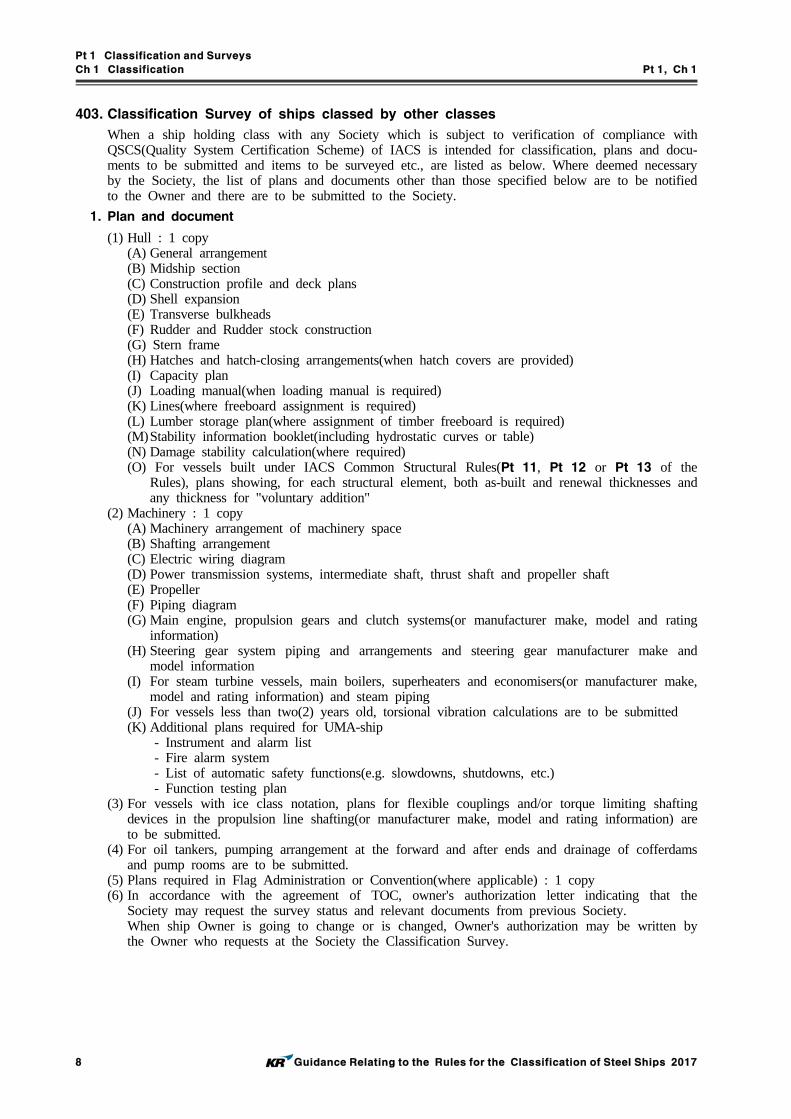
Pt 1 Classification and Surveys
Ch 1 Classification Pt 1, Ch 1
8 Guidance Relating to the Rules for the Classification of Steel Ships 2017
403. Classification Survey of ships classed by other classes
When a ship holding class with any Society which is subject to verification of compliance with QSCS(Quality System Certification Scheme) of IACS is intended for classification, plans and docu-ments to be submitted and items to be surveyed etc., are listed as below. Where deemed necessary by the Society, the list of plans and documents other than those specified below are to be notified to the Owner and there are to be submitted to the Society.
1. Plan and document
(1) Hull : 1 copy(A) General arrangement(B) Midship section(C) Construction profile and deck plans(D) Shell expansion(E) Transverse bulkheads(F) Rudder and Rudder stock construction(G) Stern frame(H) Hatches and hatch-closing arrangements(when hatch covers are provided)(I) Capacity plan(J) Loading manual(when loading manual is required)(K) Lines(where freeboard assignment is required)(L) Lumber storage plan(where assignment of timber freeboard is required)(M)Stability information booklet(including hydrostatic curves or table)(N) Damage stability calculation(where required)(O) For vessels built under IACS Common Structural Rules(Pt 11, Pt 12 or Pt 13 of the
Rules), plans showing, for each structural element, both as-built and renewal thicknesses and any thickness for "voluntary addition"
(2) Machinery : 1 copy(A) Machinery arrangement of machinery space(B) Shafting arrangement(C) Electric wiring diagram(D) Power transmission systems, intermediate shaft, thrust shaft and propeller shaft(E) Propeller(F) Piping diagram(G) Main engine, propulsion gears and clutch systems(or manufacturer make, model and rating
information)(H) Steering gear system piping and arrangements and steering gear manufacturer make and
model information(I) For steam turbine vessels, main boilers, superheaters and economisers(or manufacturer make,
model and rating information) and steam piping(J) For vessels less than two(2) years old, torsional vibration calculations are to be submitted(K) Additional plans required for UMA-ship - Instrument and alarm list - Fire alarm system - List of automatic safety functions(e.g. slowdowns, shutdowns, etc.) - Function testing plan
(3) For vessels with ice class notation, plans for flexible couplings and/or torque limiting shafting devices in the propulsion line shafting(or manufacturer make, model and rating information) are to be submitted.
(4) For oil tankers, pumping arrangement at the forward and after ends and drainage of cofferdams and pump rooms are to be submitted.
(5) Plans required in Flag Administration or Convention(where applicable) : 1 copy(6) In accordance with the agreement of TOC, owner's authorization letter indicating that the
Society may request the survey status and relevant documents from previous Society.When ship Owner is going to change or is changed, Owner's authorization may be written by the Owner who requests at the Society the Classification Survey.

Pt 1 Classification and Surveys
Ch 1 Classification Pt 1, Ch 1
Guidance Relating to the Rules for the Classification of Steel Ships 2017 9
(7) Others(A) A copy of survey reports(including Ship's Particulars and Initial Records)(B) Copies of Classification Certificate, Statutory Certificate and Certificate of Registry(C) Others indicating the ship's history and other particulars if necessary.(D) Hull Executive Summary(where required)
(8) Additional documents required for approval of alternative design and arrangements(A) Document(s) of approval of alternative design and arrangements are to be submitted, if any.
2. In case that the plans and documents considered equivalent to those specified in Par 1 are sub-mitted, they may be accepted at the discretion of the Society.
3. Where any of the following cases is applicable at the moment of Classification Survey of ships classed by other classes, the submission of plan and documents is to be in accordance with 402. (However, 3 copies of plans for alterations are to be submitted)(1) change of service area to higher grade(2) alterations or conversions(3) change of ship's use(4) application of additional requirements due to change of ship's nationality.
4. Classification Survey
Classification Surveys may be, but are not required to be, credited as periodical surveys for main-tenance of classification. Recommendations and/or conditions of class due for compliance at a specified periodical survey for maintenance of classification need not be carried out/complied with at a Classification Survey unless the Classification Survey is credited as the specified periodical survey for maintenance of classification or the recommendation/condition of classification is overdue.(1) When a ship is classed by the Society as a results of transfer of class
(A) Notwithstanding the records indicating that all surveys are up-to-date, a Classification Survey is to be held as minimum technical requirements by the Society, the extent of which is to be based on the age of the vessel and the losing Society's class status as follows: However, the Society is to request, if necessary, more strict surveys than the following requirements according to the condition of ship.(a) Hull Classification Survey
(i) For vessels of age less than 5 years the survey is to take the form of an Annual Survey.
(ii) For vessels between 5 and 10 years of age, the survey is to include the scope of an Annual Survey and inspection of a representative number of ballast spaces.
(iii) For vessels of 10 years of age and above but less than 20 years of age, the survey is to include the scope of an Annual Survey and inspection of a representative num-ber of ballast spaces and cargo spaces. For gas carriers, in lieu of internal in-spection of cargo spaces, the following applies:- Inspection of representative spaces surrounding cargo tanks, including external in-
spection of the tank and its supporting systems as far as possible;- Review of cargo log books and operational record to verify the correct functioning
of the cargo containment system.(iv) For vessels subject to ESP notation(Bulk carrier, Oil tanker and Chemical tanker,
etc.), which are 15 years of age and above but less than 20 years of age, the sur-vey is to have the scope of a Special Survey or an Intermediate Survey whichever is due next.
(v) For all vessels, which are 20 years of age and above, the survey is to have the scope of a Special Survey. This requirement is also applicable to the vessels having their hull under continuous survey.
(vi) In lieu of the requirements in items (i) through (v), the following apply for site specific purpose-built Floating Production and/or Storage Vessels:
① for vessels of age less than 5 years, the survey is to have the scope of an Annual Survey.
➁ for vessels of age between 5 and 10 years, the survey is to include the scope of an Annual Survey and inspection of 20 % of ballast tanks.

Pt 1 Classification and Surveys
Ch 1 Classification Pt 1, Ch 1
10 Guidance Relating to the Rules for the Classification of Steel Ships 2017
➂ for vessels of age between 10 and 20 years, the survey is to include the scope of an Annual Survey, inspection of 20 % of ballast tanks and 20 % of cargo spaces.
➃ for vessels of 20 years of age and above, the survey is to have the scope of a Special Survey.
(vii) The following apply for site specific purpose-built Floating Production and/or Storage Vessels which have been converted from other vessels.
➀ until 20 years have elapsed since conversion, the survey is to have the scope of an Annual Survey, inspection of 20 % of ballast tanks and 20 % of cargo spaces.
➁ after 20 years have elapsed since conversion, the survey is to have the scope of a Special Survey.
(viii) In the context of applying (iv) and (v) above, if a dry-docking of the vessel is not due at the time of Classification Survey of ships classed by other classes, con- sideration can be given to carrying out an underwater examination in lieu of dry-docking. But, for fishing vessels with Korean flag, which exceed 20 years of age, and 100 gross tonnage, docking survey is to be carried out in lieu of In-water Survey. (2016)
(ix) in the context of applying iv) and v), as applicable, the anchors and anchor chain cables ranging and gauging for vessels over 15 years of age is not required to be carried out as part of the Classification Survey unless the Classification Survey is being credited as a periodical survey for maintenance of class. If the Classification Survey is to be credited as a periodical survey for maintenance of class, consid-eration may be given by the Society to the acceptance of the anchors and anchor chain cables ranging and gauging carried out by the losing Society provided they were carried out within the applicable survey window of the periodical survey in question.
(x) In the context of applying (i) to (viii) above, as applicable, consideration may be given by the Society to the acceptance of thickness measurements taken by the los-ing society provided;① if the Classification Survey is to be credited as a periodical survey for main-
tenance of class, they were carried out within the applicable survey window of the periodical survey in question.
② if the Classification Survey is not to be credited as a periodical survey for maintenance of class, they were carried out;- within 15 months prior to completion of Classification Survey when it is in
the scope of a Special Survey,- within 18 months prior to completion of Classification Survey when it is in
the scope of an Intermediate Survey.In ① and ② both cases, the thickness measurements are to be reviewed by the Society for compliance with the applicable survey requirements, and confirmatory gaugings are to be taken to the satisfactory of the Society.
(xi) In the context of applying (iii) to (viii) above, as applicable, tank pressure testing for vessels over 15 years of age is not required to be carried out as part of the Classification Survey unless the Classification Survey is being credited as a period-ical survey for maintenance of class. If the Classification Survey is to be credited as a periodical survey for maintenance of class, consideration may be given by the Society to the acceptance of the tank pressure testing carried out by the losing Society provided they were carried out within the applicable survey window of the periodical survey in question.
(xii) In the context of applying (i) to (viii) above, as applicable, compliance with IACS Unified Requirements that require compliance at the forthcoming due periodical sur-veys (such as S26(Strength and Securing of Small Hatches on the Exposed Fore Deck) and S27(Strength Requirements for Fore Deck Fittings and Equipment)) are not required to be carried out/completed as part of the Classification Survey unless the Classification Survey is credited as a periodical survey for maintenance of class.

Pt 1 Classification and Surveys
Ch 1 Classification Pt 1, Ch 1
Guidance Relating to the Rules for the Classification of Steel Ships 2017 11
(b) Machinery Classification SurveyA general examination of all essential machinery is to be held and included:(i) The adjustment of all boiler, economizer and steam generator safety valves are to be
verified and oil fuel burning equipment examined under working conditions.(ii) All pressure vessels are to be identified with the submitted plans and/or certificates.(iii) Insulation resistance, generator circuit breakers, preference tripping relays and gen-
erator prime mover governors are to be tested and paralleling and load distributing to be proved.
(iv) In all cases, navigation lights and indicators are to be examined under working con-dition and alternative source of supply to be verified.
(v) Bilge pumping and oil fuel burning installations, together with emergency fire pump and remote controls for oil valves, oil fuel pumps, lubricating oil pumps and forced draught fans are to be examined and tested under working conditions.
(vi) Recirculating and ice clearing arrangements are to be verified as conforming to Rule requirements(When ice class is required).
(vii) The main and all auxiliary machinery necessary for operation of the ship at sea to-gether with essential controls and steering gear are to be tested under working conditions. Alternative means of steering are to be tested. A short sea trial may be held at the Surveyor's discretion if the ship has been laid up for a long period.
(viii) Initial start arrangements are to be verified.(ix) In the case of oil tankers, the cargo oil system and electrical installation in way of
dangerous spaces are to be checked for compliance with rule requirements. Where explosion protected electrical safe equipment is installed, the Surveyors are to con-firm themselves that such equipment has been approved by a recognised authority. The safety devices, alarms and essential instruments of inert gas system are to be verified and the plant generally examined to ensure that it does not constitute a haz-ard to the ship.
Note : For the transfer of class or adding class as a double classed vessel or a dual classed vessel at ship's delivery after completion of the new construction survey of other society, items (iii) and (ix) may be verified by reviewing the ship's record.
(B) For vessels less than 15 years of age, an Interim Certificate of Class, or other documents enabling the vessel to trade are not to be issued, until all relevant surveys specified in (A) above have been satisfactorily completed; until all overdue surveys and all overdue recom-mendations/conditions of class previously issued against the subject vessel as specified to the Owner by the losing Society, have been completed and rectified by the Society.For vessels 15 years of age and above, an Interim Certificate of Class, or other documents enabling the vessel to trade are not to be issued, until all relevant surveys specified in (A) above have been satisfactorily completed; until all overdue surveys and all overdue recom-mendations/conditions of class previously issued against the subject vessel as specified to the Owner by the losing Society, have been completed and rectified by the losing Society.When facilities are not available in the first port of survey, an Interim Certificate of Class may be issued to allow the vessel to undertake a direct voyage to a port where facilities are available to complete the surveys required in (A) above. In such cases, the surveys specified in (A) above are to be carried out to the maximum extent practicable at the first port of survey, but in no case less than the scope of annual hull survey and machinery sur-veys as required in (A) (b).
(C) The validity of the Interim Certificate of Class and the subsequent Certificate of Class is subject to any outstanding recommendations/conditions of class previously issued against the vessel being completed by the due and as specified by the losing Society. Any outstanding recommendations/conditions of class with their due dates are to be clearly stated on the:(a) Interim Certificate of Class and/or class survey record available on board; and(b) Survey status when the Certificate of Class is issued.
(D) Any additional information regarding outstanding surveys or recommendations/conditions of class received from the losing Society is to be dealt with in accordance with above (B) and (C) as applicable. If this additional information is received after the Interim Certificate of Classification has been issued, any surveys or recommendations/conditions of class which are overdue are to be dealt with at the first port of call:(a) by the Society in vessels less than 15 years of age; or(b) by the losing Society in vessels 15 years of age or over
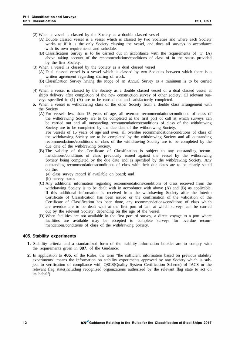
Pt 1 Classification and Surveys
Ch 1 Classification Pt 1, Ch 1
12 Guidance Relating to the Rules for the Classification of Steel Ships 2017
(2) When a vessel is classed by the Society as a double classed vessel(A) Double classed vessel is a vessel which is classed by two Societies and where each Society
works as if it is the only Society classing the vessel, and does all surveys in accordance with its own requirements and schedule.
(B) Classification Survey is to be carried out in accordance with the requirements of (1) (A) above taking account of the recommendations/conditions of class of in the status provided by the first Society.
(3) When a vessel is classed by the Society as a dual classed vessel(A) Dual classed vessel is a vessel which is classed by two Societies between which there is a
written agreement regarding sharing of work.(B) Classification Survey having the scope of an Annual Survey as a minimum is to be carried
out.(4) When a vessel is classed by the Society as a double classed vessel or a dual classed vessel at
ship's delivery after completion of the new construction survey of other society, all relevant sur-veys specified in (1) (A) are to be carried out and satisfactorily completed.
5. When a vessel is withdrawing class of the other Society from a double class arrangement with the Society(A) For vessels less than 15 years of age, all overdue recommendations/conditions of class of
the withdrawing Society are to be completed at the first port of call at which surveys can be carried out and all outstanding recommendations/conditions of class of the withdrawing Society are to be completed by the due date of the withdrawing Society.For vessels of 15 years of age and over, all overdue recommendations/conditions of class of the withdrawing Society are to be completed by the withdrawing Society and all outstanding recommendations/conditions of class of the withdrawing Society are to be completed by the due date of the withdrawing Society.
(B) The validity of the Certificate of Classification is subject to any outstanding recom-mendations/conditions of class previously issued against the vessel by the withdrawing Society being completed by the due date and as specified by the withdrawing Society. Any outstanding recommendations/conditions of class with their due dates are to be clearly stated on the:(a) class survey record if available on board; and(b) survey status
(C) Any additional information regarding recommendations/conditions of class received from the withdrawing Society is to be dealt with in accordance with above (A) and (B) as applicable. If this additional information is received from the withdrawing Society after the Interim Certificate of Classification has been issued or the confirmation of the validation of the Certificate of Classification has been done, any recommendations/conditions of class which are overdue are to be dealt with at the first port of call at which surveys can be carried out by the relevant Society, depending on the age of the vessel.
(D) When facilities are not available in the first port of survey, a direct voyage to a port where facilities are available may be accepted to complete surveys for overdue recom-mendations/conditions of class of the withdrawing Society.
405. Stability experiments
1. Stability criteria and a standardized form of the stability information booklet are to comply with the requirements given in 307. of the Guidance.
2. In application to 405. of the Rules, the term "the sufficient information based on previous stability experiments" means the information on stability experiments approved by any Society which is sub-ject to verification of compliance with QSCS(Quality System Certification Scheme) of IACS or the relevant flag state(including recognized organizations authorized by the relevant flag state to act on its behalf)
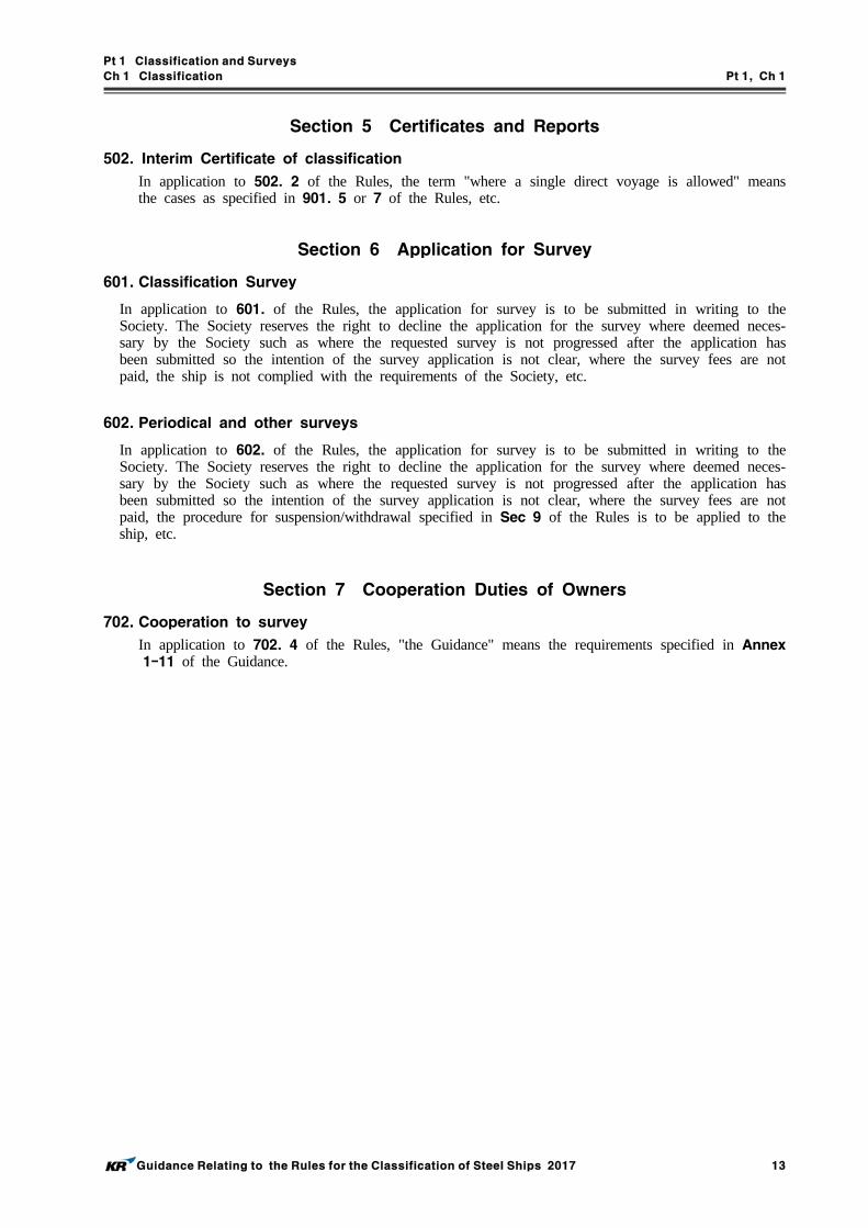
Pt 1 Classification and Surveys
Ch 1 Classification Pt 1, Ch 1
Guidance Relating to the Rules for the Classification of Steel Ships 2017 13
Section 5 Certificates and Reports
502. Interim Certificate of classification
In application to 502. 2 of the Rules, the term "where a single direct voyage is allowed" means the cases as specified in 901. 5 or 7 of the Rules, etc.
Section 6 Application for Survey
601. Classification Survey
In application to 601. of the Rules, the application for survey is to be submitted in writing to the Society. The Society reserves the right to decline the application for the survey where deemed neces-sary by the Society such as where the requested survey is not progressed after the application has been submitted so the intention of the survey application is not clear, where the survey fees are not paid, the ship is not complied with the requirements of the Society, etc.
602. Periodical and other surveys
In application to 602. of the Rules, the application for survey is to be submitted in writing to the Society. The Society reserves the right to decline the application for the survey where deemed neces-sary by the Society such as where the requested survey is not progressed after the application has been submitted so the intention of the survey application is not clear, where the survey fees are not paid, the procedure for suspension/withdrawal specified in Sec 9 of the Rules is to be applied to the ship, etc.
Section 7 Cooperation Duties of Owners
702. Cooperation to survey
In application to 702. 4 of the Rules, "the Guidance" means the requirements specified in Annex 1-11 of the Guidance.

Pt 1 Classification and Surveys
Ch 1 Classification Pt 1, Ch 1
14 Guidance Relating to the Rules for the Classification of Steel Ships 2017
Section 8 Competence and Duties of Surveyors
801. Competence of Surveyors
1. Request of additional survey
The Surveyor may request additional surveys even though they are not specified as the survey items for the relevant kind of survey or may increase the extent of the relevant survey considering the following items and so on, if deemed necessary by the Surveyor.(1) where abnormality is suspect from the survey on the survey items for the relevant kind of sur-
vey(2) where abnormality such as record or indication of abnormal deterioration, etc. is suspect(3) where substantial corrosion, significant deformation, fracture, damage or other defect is evident
or suspect(4) information from the records of maneuvering, operation, maintenance, measurement, etc. and in-
formation from the ship(ship officers, crews) or maker(5) the relevant technical information on defects from similar ships or similar survey objects ac-
cording to available information
2. Request of non-destructive examination
The Surveyor may request non-destructive examinations or may increase the extent of the non-de-structive examinations considering the following items and so on, if deemed necessary by the Surveyor.(1) where injurious defect is evident or suspect at surface and/or inside of materials, welding or re-
paired defect, etc.(2) the areas where workmanship is suspect, where new manufacture/welding methods have been
adopted, where defects are liable to occur easily, where working conditions such as accessability are not good, etc.
(3) items specified in 1 (1) to (5) above
3. Request of thickness measurement
The Surveyor may request thickness measurements or may increase the extent of the thickness measurements considering the following items and so on, if deemed necessary by the Surveyor.(1) where wastage is evident or suspect(2) where considered to be prone to rapid wastage(3) where there is no protective coating or abnormality in protective coating condition such as
breakdown of coating, etc. is evident or suspect(4) items specified in 1 (1) to (5) above
4. Request of pressure test
The Surveyor may request pressure tests or may increase the extent of the pressure tests consider-ing the following items and so on, if deemed necessary by the Surveyor.(1) where abnormality is suspect from the external examination(2) where applicant has not carried out sufficient self-inspection for leak test which is adopted in-
stead of pressure test(3) items specified in 1 (1) to (5) above
5. Request of Close-up Survey
The Surveyor may request Close-up Surveys or may increase the extent of the Close-up Surveys considering the following items and so on, if deemed necessary by the Surveyor.(1) where abnormality such as substantial corrosion or structural defects, etc. is suspect from the
Overall Survey(2) the maintenance of the relevant space and the condition of the corrosion prevention system(3) items specified in 1 (1) to (5) above
6. Request of open-up survey, internal examination and/or performance test
The Surveyor may request open-up surveys, internal examinations and/or performance tests or may increase the extent of the open-up surveys, internal examinations and/or performance tests consider-ing the following items and so on, if deemed necessary by the Surveyor.(1) where abnormality is suspect from the external examination and/or operation test(2) items specified in 1 (1) to (5) above

Pt 1 Classification and Surveys
Ch 1 Classification Pt 1, Ch 1
Guidance Relating to the Rules for the Classification of Steel Ships 2017 15
7. If the Surveyor considers the working conditions are unsafe or encounters the working conditions that may compromise the safety of the Surveyor, the Surveyor may stop or refuse surveys immedi-ately until the working conditions are safe to do so.
Section 9 Suspension/Withdrawal of Class and Reclassification
901. Suspension/Reinstatement of class
In application to 901. 1 and 6 of the Rules, the surveys to be carried out for reinstatement of class are to be based upon the survey requirements at the original date due and not on the age of the vessel when the survey is carried out.
902. Withdrawal of class
When a ship classed with the Society is detained following a Port State Control inspection with se-rious deficiencies found, the class of the ship may be suspended or withdrawn through the deliber-ation of the Classification Committee.
Section 13 Classification of Other Installations or Equipment
1301. Classification
In application to 1301. of the Rules, Annex 1-1 of the Guidance is to be referred for the assign-ment of the class notation.
1303. Construction and Survey
In application to 1303. of the Rules, "the Guidance" means the requirements specified in related Rules.
1304. Maintenance of classification
In application to 1304. of the Rules, "the requirements specified by the Society" means the re-quirements specified in the relevant technical rules of the Society.

Pt 1 Classification and Surveys
Ch 2 Periodical and Other Surveys Pt 1, Ch 2
Guidance Relating to the Rules for the Classification of Steel Ships 2017 17
CHAPTER 2 PERIODICAL AND OTHER SURVEYS
Section 1 General
101. Definitions
In application to 101. 11 of the Rules, the term "location prone to rapid wastage" means one of the following cases among the location specified in Annex 1-5, Table 2 of the Guidance:(1) Area with standing bilges(2) Bulkheads facing fuel oil tanks being heated
104. Execution of heavier survey
In application to 104. of the Rules, the term "as specially considered necessary by the Surveyor" means the cases as specified in Ch 1, 801. of the Guidance.
106. Tests
In application to 106. 2 of the Rules, "significant repairs" means the repairs may affect on the ship’s speed or steering performance such as change of the main propulsion engine or the auxiliary engine, over 10% change of output of the main propulsion engine or the auxiliary engine, change of shape or main dimension of the propeller and change of the steering gear or steering capability.
107. Repairs
1. In application to 107. 2 of the Rules, "affects or, in the opinion of the Surveyor, will affect the vessel's structural, watertight or weathertight integrity" means the case where the Surveyor consid-ered that the vessel's intended voyages or services are not able to be achieved safely because of the damages in vessel's structure, including buckling, grooving, detachment or fracture, or the lose of vessel's watertight or weathertight integrity.
2. In application to 107. 4 of the Rules, "when a survey results in the identification of structural de-fects or corrosion, either of which, in the opinion of the Surveyor, will impair the vessel's fitness for continued service" means the case where the Surveyor considered that the vessel's intended voy-ages or services are not able to be achieved safely because of defects or corrosion identified from the survey results.
3. In application to 107. 6 (1) of the Rules, the "emergency circumstance" means the circumstance which affect or may affect the ships maneuvering, survival, marine pollution or protection of the cargoes directly.
108. Wear limit on structural members
In application to 108. of the Rules, the terms "considered suitable" or "deemed appropriate by the Society" mean to comply with the requirements specified in Pt 2 and Pt 3 of the Rules.
109. Procedures for thickness measurements
1. In application to 109. 1 of the Rules, "an appropriately qualified representative" means a ship's officer.
2. Methods of thickness measurement are to comply with the requirements specified in Annex 1-5 of the Guidance.

Pt 1 Classification and Surveys
Ch 2 Periodical and Other Surveys Pt 1, Ch 2
18 Guidance Relating to the Rules for the Classification of Steel Ships 2017
110. Preparations for survey
1. In application to 110. 1 (6) and (7) of the Rules, the Surveyor is to consider following items and so on when require to remove casings, ceilings or linings, and loose insulation.(1) where abnormality such as record or indication of abnormal deterioration, etc. is suspect(2) where substantial corrosion, significant deformation, fracture, damage or other defect is evident
or suspect(3) where wastage is evident or suspect(4) where considered to be prone to rapid wastage
2. In application to 110. 1 (7) of the Rules, "insulations in way" means the extent of insulations to determine the extent of the poor coating condition behind the insulation.
3. In application to 110. 3 (2) of the Rules, "deemed necessary by the Surveyor" means the cases as specified in Ch 1, 801. 2 of the Guidance.
4. In application to 110. 4 (4) of the Rules, "at the sole discretion of the Surveyor" means the cases as specified in Ch 3, 102. 6 (3) of the Rules.

Pt 1 Classification and Surveys
Ch 2 Periodical and Other Surveys Pt 1, Ch 2
Guidance Relating to the Rules for the Classification of Steel Ships 2017 19
Section 2 Annual Survey
202. Hull, equipment and fire-extinguishing appliances
1. In application to 202. 1 (20) of the Rules, "considered necessary by the Surveyor" means the cases as specified in Ch 1, 801. 6 of the Guidance.
2. In application to 202. 1 (31) of the Rules, "considered necessary by the Surveyor" means the cases as specified in Ch 1, 801. 3 of the Guidance.
3. In application to 202. 2 of the Rules, the following items are to be surveyed. (2017)(1) Examining the fire pumps, fire main, hydrants, hoses and nozzles and the international shore
connection and checking that each fire pump, including the emergency fire pump, can be oper-ated separately so that two jets of water are produced simultaneously from different hydrants at any part of the ship whilst the required pressure is maintained in the fire main.
(2) Checking the provision and randomly examining the condition of the portable and non-portable fire extinguishers.
(3) Confirming that the fire fighter's outfits and emergency escape breathing devices(EEBDs) are complete and in good condition and that the cylinders, including the spare cylinders, of any re-quired self contained-breathing apparatus are suitably charged, and that on board means of re-charging breathing apparatus used during drills or a suitable number of spare cylinders to re-place those used are provided, and provision of two-way portable radiotelephone apparatus of an explosion-proof type or intrinsically safe. (SOLAS 74/00/12, Reg.II-2 /10.10) (2017)
(4) Checking the operational readiness and maintenance of fire fighting systems.(5) Examining the fixed fire fighting system for the machinery, cargo, vehicle, special category and
ro-ro spaces, as appropriate, and confirming that its means of operation is clearly marked.(6) Examining the fire-extinguishing and special arrangements in the machinery spaces and confirm-
ing, as far as practicable and as appropriate, the operation of the remote means of control pro-vided for the opening and closing of the skylights, the release of smoke, the closure of the fun-nel and ventilation openings, the closure of power operated and other doors, the stopping of ventilation and boiler forced and induced draft fans and the stopping of oil fuel and other pumps that discharge flammable liquids.
(7) Checking that fixed carbon dioxide fire-extinguishing systems for the protection of machinery spaces and cargo pump-rooms, where applicable, are provided with two separate controls, one for opening of the gas piping and one for discharging the gas from the storage container, each of them located in a release box clearly identified for the particular space.
(8) Examining, as far as possible, and testing, as feasible, any fire detection and alarm system and any sample extraction smoke detection system.
(9) Examining the fire-extinguishing systems for spaces containing paint and/or flammable liquids and deep-fat cooking equipment in accommodation and service spaces.
(10) Examining the helicopter facilities.(11) Examining the arrangements for remote closing of valves for oil fuel, lubricating oil and other
flammable oils and confirming, as far as practicable and as appropriate, the operation of the re-mote means of closing the valves on the tanks that contain oil fuel, lubricating oil and other flammable oils.
(12) Examining and testing of the general emergency alarm system.(13) Examining, where applicable, the alternative design and arrangements for fire safety appliances
and arrangements, in accordance with the test, inspection and maintenance requirements, if any, specified in the approved documentation. (2017)
(14) Examining, when appropriate, the special arrangements for carrying dangerous goods, including checking the electrical equipment and wiring, the ventilation, the provision of protective clothing and portable appliances and the testing of the water supply, bilge pumping and any water spray system. (2017)

Pt 1 Classification and Surveys
Ch 2 Periodical and Other Surveys Pt 1, Ch 2
20 Guidance Relating to the Rules for the Classification of Steel Ships 2017
203. Machinery, electrical installations and additional installations
1. In application to 203. 21 of the Rules, the term "considered satisfactory by the Surveyor" means the other cases except for the cases as specified in Ch 1, 801. 6 of the Guidance.
2. In application to 203. 22 of the Rules, "the Guidance" means the requirements specified in Annex 1-9 of the Guidance.
3. In application to 203. 26 of the Rules, the term "considered necessary by the Surveyor" means the cases as specified in Ch 1, 801. 6 of the Guidance.
4. In application to 203. 27 of the Rules, where the electrical distribution system on board a ship in-cludes harmonic filters but facilities to continuously monitor harmonic distortion levels experienced on the main busbar are not fitted, following requirements for measurement of the harmonic dis-tortion levels are to be applied. (2017)(1) Harmonic distortion levels are to be measured as close to the Annual Survey as possible so as
to give a clear representation of the condition of the entire plant to the Surveyor. (2017)(2) Harmonic distortion readings are to be carried out when the greatest amount of distortion is in-
dicated by the measuring equipment. (2017)(3) An entry showing which equipment was running and/or filters in service is to be recorded in
the log so this can be replicated for the next periodical survey. (2017)(4) Harmonic distortion levels are also to be measured following any modification to the ship's
electrical distribution system or associated consumers by suitably trained ship's personnel or from a qualified outside source. (2017)
204. Additional requirements to ship types
1. In application to 204. 1 to 3 of the Rules, the term "considered necessary by the Surveyor" means the cases as specified in Ch 1, 801. 6 of the Guidance.
2. In application to 204. 1 (2) (H) of the Rules, the term "where necessary" means the cases as specified in Ch 1, 801. 6 of the Guidance.

Pt 1 Classification and Surveys
Ch 2 Periodical and Other Surveys Pt 1, Ch 2
Guidance Relating to the Rules for the Classification of Steel Ships 2017 21
Section 3 Intermediate Survey
301. Due range
In application to 301. 3 of the Rules, "Intermediate Survey items" means the following items among all survey items of Intermediate Survey.(1) Compartments survey(except compartments which are to be surveyed at each periodical survey)(2) Thickness measurement(3) Docking Survey as a part of Intermediate Survey(except the ships of which Docking Survey is
to be carried out at each periodical survey)(4) Overhauling survey of machinery(except the ships subject to CMS or PMS)
302. Hull, equipment and fire-extinguishing appliances
In application to 302. 2 of the Rules, "the Guidance" means the requirements specified in 202. of the Guidance. In this case, for foam fire-extinguishing systems, the foam is to be tested by the manufacturer or recognized test organization and the test records are to be submitted for approval.
303. Machinery, electrical installations and additional installations
1. In application to 303. 1 (1) of the Rules, the term "deemed unnecessary by the Surveyor" means the other cases except for the cases as specified in Ch 1, 801. 6 of the Guidance.
2. In application to 303. 2 (1) and (1) (A) of the Rules, the term "deemed necessary by the Surveyor" means the cases as specified in Ch 1, 801. 6 of the Guidance.
3. In application to 303. 2 (2) of the Rules, high-rotating-speed internal combustion engines of specif-ic construction refer to those which comply with the formulae below and which can not be in-cluded in a survey of the crankshaft and bearings without complete engine overhaul.
×∙
≥ , ×∙∙
≥
where,
: Stroke (mm) : Maximum continuous revolution (rpm ) : Diameter of crankshaft journal (mm)
4. In application to 303. 2 (3) of the Rules, "the Guidance" means that it is to be confirmed that the requirements specified in 902. 3 apply to the ship.
5. In application to 303. 4 of the Rules, the term "deemed necessary by the Surveyor" means the cases as specified in Ch 1, 801. 6 of the Guidance.
6. In application to 303. 5 of the Rules, the term "deemed necessary by the Surveyor" means the cases as specified in Ch 1, 801. 6 of the Guidance.
7. In application to 303. 6 of the Rules, "the Guidance" means the requirements specified in Annex 1-9 of the Guidance.

Pt 1 Classification and Surveys
Ch 2 Periodical and Other Surveys Pt 1, Ch 2
22 Guidance Relating to the Rules for the Classification of Steel Ships 2017
304. Additional requirements to Ship types
In application to 304. 3 (10) of the Rules, Non-metallic membranes of pressure relief valves for cargo tanks, in principle, should be inspected every three(3) years and then replaced with new ones when they are showing probability of hardening or malfunction. However, Non-metallic membranes are may be permitted to use exceeding three(3) years subject to comply with the following inspections.(1) To be confirmed that the function test of the pressure relief valve is carried out and found in
good order. However, where deemed necessary by the surveyor in accordance with Ch 1, 801. of the Guidance, the open-up survey is to be carried out.
(2) To be confirmed that, on the basis of log-book or crew's statement, no leakage from the pres-sure relief valves during the voyage has been occurred.
(3) As a result of the examination (1) and (2) above, it is to be verified that the surface and the function of the pressure relief valves are satisfactory.

Pt 1 Classification and Surveys
Ch 2 Periodical and Other Surveys Pt 1, Ch 2
Guidance Relating to the Rules for the Classification of Steel Ships 2017 23
Section 4 Special Survey(Hull, Equipment and Fire-extinguishing Appliances)
401. Due range
1. In application to 401. 5 of the Rules, "Special Survey" means the following items among all sur-vey items of Special Survey.(1) Compartments survey(except compartments which are to be surveyed at each Periodical Survey)(2) Thickness measurement(3) Docking Survey(except the ships of which Docking Survey is to be carried out at each period-
ical survey)(4) Overhauling survey of machinery(except the ships subject to CMS or PMS)(5) Examination of 403. 1 (3) of the Rules(6) Examination of Sec 5-2, 3 of the Rules
2. For passenger ships, submersibles, nuclear ships, hydrofoils, air cushion vehicles and high speed crafts the requirements specified in 401. 4 and 5 of the Rules do not apply.
3. In application to 401. 8 (4) of the Rules, the term "deemed necessary by the Surveyor" means the cases as specified in Ch 1, 801. 1 of the Guidance.
4. In application to 401. 8 (7) of the Rules, the Society is to consider following items and so on when withdraw the approval of Continuous Survey System of hull at the discretion of the Society.(1) where Continuous Survey of hull has not been carried out satisfactorily(2) When the Continuous Survey of hull item(s) due or overdue at the time of Annual Survey is
not surveyed, or postponed by agreement(3) where withdrawal of the Continuous Survey System of hull is requested by the Owner(4) the results of reconsideration for adoption of the approved Continuous Survey System of hull
where the Owner is changed
403. Requirements of survey
1. In application to Table 1.2.2 of the Rules, the Surveyor is to consider following items and so on when require to remove ceilings, sparrings, wood linings/wood planks, floor plates and/or in-sulations, etc.(1) where abnormality such as record or indication of abnormal deterioration, etc. is suspect(2) where substantial corrosion, significant deformation, fracture, damage or other defect is evident
or suspect(3) where wastage is evident or suspect(4) where considered to be prone to rapid wastage
2. In application to Table 1.2.2 of the Rules, "considered necessary by the Surveyor" for thickness measurements means the cases as specified in Ch 1, 801. 3 of the Guidance.
3. In application to 403. 1 (7) (c) and (d) of the Rules, "deemed/considered necessary by the Surveyor" means the cases as specified in Ch 1, 801. 3 of the Guidance.
4. In application to 403. 1 (8) of the Rules, the term "deemed appropriate by the Surveyor" means the other cases except for the cases as specified in Ch 1, 801. 6 of the Guidance.
5. In application to 403. 1 (13) of the Rules, "deemed necessary" means the cases as specified in Ch 1, 801. 3 of the Guidance.
6. In application to Table 1.2.6 NOTES 5 of the Rules, "deemed necessary" means the cases as specified in Ch 1, 801. 4 of the Guidance.
7. In application to 403. 1 (15) of the Rules, the term "considered necessary by the Surveyor" means the cases as specified in Ch 1, 801. 6 of the Guidance.
8. In application to 403. 1 (19) of the Rules, "deemed necessary" means the cases as specified in Ch 1, 801. 2 of the Guidance.

Pt 1 Classification and Surveys
Ch 2 Periodical and Other Surveys Pt 1, Ch 2
24 Guidance Relating to the Rules for the Classification of Steel Ships 2017
9. In application to 403. 1 of the Rules, for ships which are to be comply with Annex 7-8, 3 of the Guidance as a safety measure for container ships incorporating extremely thick steel plates, NDT is to be carried out in accordance with Annex 7-8, 3 and Table 1 of the Guidance at No. 2 Special Survey and every even Special Survey after that(e.g. No.4, No. 6 Special Survey, etc.).
404. Fire-extinguishing appliances
In application to 404. of the Rules, “the Guidance” means the requirements specified in 302. of the Guidance.

Pt 1 Classification and Surveys
Ch 2 Periodical and Other Surveys Pt 1, Ch 2
Guidance Relating to the Rules for the Classification of Steel Ships 2017 25
Section 5-1 Special Survey(Machinery, Electrical Installations and Additional Installations)
502. Requirements of survey
1. In application to 502. 1 (1) (a) of the Rules, where total running hours for an internal combustion engine is confirmed and found in satisfactory by the Surveyor, the survey may be extended until next overhauling hours recommended by the manufacturer since the previous overhauling survey. However, the interval is not to exceed 5 years from the date of the previous overhauling survey. And the survey item of essential valves and valve arrangements are to be included the isolating non-return valve for starting air mains against explosion as specified in Pt 5, Ch 2, 203. 9 of the Rules.
2. In application to 502. 1 (1) (b) of the Rules, "the Guidance" means the following.(1) The definition of high-rotating-speed internal combustion engine is to be in accordance with 303. 3 of the Guidance, and the due date of survey is same as Par 1 above.
(2) Examination for high-rotating-speed internal combustion engines is to be done by the require-ment specified in 502. 1 (1) (a) of the Rules, but the measurement for crank web deflections may be dispensed with.
3. In application to 502. 1 (1) of the Rules, the term "deemed necessary by the Surveyor" means the cases as specified in Ch 1, 801. 6 of the Guidance.
4. In application to 502. 2 (2) to (5), (8), (10) and (12) of the Rules, the terms "deemed necessary by the Surveyor" and "considered necessary by the Surveyor" mean the cases as specified in Ch 1, 801. 6 of the Guidance.
5. In application to 502. 2 (9) (a) and (c) of the Rules, the terms "deemed necessary by the Surveyor" and "considered necessary by the surveyor" mean the cases as specified in Ch 1, 801. 4 and/or 6 of the Guidance. In application to 502. 2 (9) (b) of the Rules, the term "deemed neces-sary by the Surveyor" means the cases as specified in Pt 5, Ch 6, 1305. of the Rules when open-up surveys are carried out.
6. In application to 502. 2 (9) (b) of the Rules, open type coolers which are of air-cooled type and not of shell-and-tube type are to be examined externally instead of open-up survey.
7. In application to 502. 2 (12) of the Rules, the term "as necessary" means the cases as specified in Ch 1, 801. 3 of the Guidance.
8. In application to 502. 3 (4) of the Rules, the term "deemed necessary by the Surveyor" means the cases as specified in Ch 1, 801. 6 of the Guidance.
9. In application to 502. 4 of the Rules, "the Guidance" means the requirements specified in Annex 1-9 of the Guidance.

Pt 1 Classification and Surveys
Ch 2 Periodical and Other Surveys Pt 1, Ch 2
26 Guidance Relating to the Rules for the Classification of Steel Ships 2017
Section 5-2 Special Survey(Additional Requirements to Ship Types)
1. In application to Sec 5-2, 1 (4) of the Rules, the term "considered necessary by the Surveyor" means the cases as specified in Ch 1, 801. 3 and/or 4 of the Guidance.
2. In application to Sec 5-2, 1 (5) of the Rules, the term "when appropriate" means the cases as specified in Ch 1, 801. 6 of the Guidance.
3. In application to Sec 5-2, 3 (1) (B) of the Rules, the Surveyor is to consider following items and so on when require to remove insulations.(1) where abnormality such as record or indication of abnormal deterioration, etc. is suspect(2) where substantial corrosion, significant deformation, fracture, damage or other defect is evident
or suspect(3) where wastage is evident or suspect(4) where considered to be prone to rapid wastage
4. In application to Sec 5-2, 3 (1) (C) of the Rules, the term "deemed necessary by the Surveyor" means the cases as specified in Ch 1, 801. 2 of the Guidance.
5. In application to Sec 5-2, 3 (4) of the Rules, the term "as necessary" means the cases as speci-fied in Ch 1, 801. 6 of the Guidance.
6. In application to Sec 5-2, 3 (6) (A) of the Rules, the Surveyor is to consider following items and so on when require to remove insulations.(1) where abnormality such as record or indication of abnormal deterioration, etc. is suspect(2) where substantial corrosion, significant deformation, fracture, damage or other defect is evident
or suspect(3) where wastage is evident or suspect(4) where considered to be prone to rapid wastage
7. In application to Sec 5-2, 3 (8) (A) of the Rules, the term "deemed necessary" means the cases as specified in Ch 1, 801. 1 of the Guidance.

Pt 1 Classification and Surveys
Ch 2 Periodical and Other Surveys Pt 1, Ch 2
Guidance Relating to the Rules for the Classification of Steel Ships 2017 27
Section 6 Docking Survey
601. Due range
The docking survey intervals for passenger ship engaged on international voyages are to be subject to the relevant requirements of the International Convention for Safety of Life at Sea. But in five-year Special Survey period two times of Docking Survey with an interval not exceeding 36 months from the completion date of the previous Docking Survey and three times of In-water Survey specified in 604. of the Rules in lieu of the Docking Survey may be carried out. However, where specific requirements are provided by the Administration the relevant requirements are to be applied.
603. Requirements of survey
1. In application to 603. 2 of the Rules, the term "special attention" means a careful examination of the connection between the bilge strakes and the bilge keels.
2. In application to 603. 3 of the Rules, the term "considered necessary by the Surveyor" in that "If considered necessary by the Surveyor, the rudder is to be lifted or the inspection plates removed for the examination of pintles." means the cases as specified in Ch 1, 801. 1 of the Guidance.
3. In application to 603. 3 of the Rules, the term "as deemed necessary" in that "the pressure test of the rudder may be required as deemed necessary by the Surveyor." means the case which repair work relating with the air tightness of rudder is done and/or the cases as specified in Ch 1, 801. 1 of the Guidance.
4. In application to 603. 4 and 5 of the Rules, the term "considered necessary by the Surveyor" means the cases as specified in Ch 1, 801. 6 of the Guidance.
5. In application to 603. 6 of the Rules, "the Guidance" means the requirements specified in Annex 1-9 of the Guidance.
604. In-water Survey
1. In application to 604. 1 of the Rules, survey status, latest docking survey reports and thickness measurement records, etc. are to be considered when special consideration is given.
2. In application to 604. 3 (7) (a) of the Rules, the term "deemed necessary by the Surveyor" means the cases where the damage of internal structural member is evident or suspect, the cases as speci-fied in Ch 1, 801. 3 and/or 6 of the Guidance.
3. In application to 604. 3 (8) (d) (iii) of the Rules, the term "deemed appropriate by the Society" means the cases where name plate, signal device and/or position indicating device, etc. is provided so that the diver is able to orient his/her position relative to the ship.
605. Extended Dry-docking Interval System
1. In application to 605. 1 (3) of the Rules, the term "deemed appropriate by the Society" means the cases where all requirements specified in 605. of the Rules are comply with.
2. In application to 605. 1 (6) of the Rules, the term "if it is determined that a dry-docking is neces-sary" means the following cases and so on.(1) where the necessary requirements for Extended Dry-docking Interval System are not comply
with(2) where Docking Survey is necessary from the result of In-water Survey reveals damage or dete-
rioration that requires repair(3) where withdrawal for application of the Extended Dry-docking Interval System is requested by
the Owner(4) where Docking Survey is necessary from the results of reconsideration for application of the
approved Extended Dry-docking Interval System where the Owner or flag is changed

Pt 1 Classification and Surveys
Ch 2 Periodical and Other Surveys Pt 1, Ch 2
28 Guidance Relating to the Rules for the Classification of Steel Ships 2017
Section 7 Surveys of Propeller Shaft and Stern Tube Shaft, Etc.
701. General
1. In application to 701. 2 of the Rules, "the Guidance" means the requirements specified in Annex 1-9 of the Guidance.
2. In application to 701. 3 (15) of the Rules, reference for Fresh water sample test is made to IACS Rec.36(Recommended procedure for the determination of contents of materials and other con-taminants in stern tube lubricating oil).
3. In application to 701. 3 (19) of the Rules, a ships with oil lubricated stern tube bearing applying an approved Condition Monitoring Scheme is to be comply with the followings and is to be as-signed an additional installation notation of STCM. (2017)(1) The following systems are to be provided and relevant drawings are to be submitted for
approval.(A) At the aft stern tube bearing, two temperature sensors are to be provided, or if only one
temperature senor is provided, a spare temperature sensor which can be replaced easily is to be provided when the using sensor is out of order.
(B) Measurement of bearing weardown is to be provided.(C) Oil seals devices are to be such that can be renewed without removal of propeller.
(2) The following are carried out at each shaft survey due date required by 702. 3 (1) of the Rules(A) Survey required by 702. 1 (2) (A) or (B) of the Rules(B) Survey required by 702. 1 (2) (D) (E) (F) and (G) of the Rules
(3) the Surveyor confirms at the periodical survey that parameters in the following condition mon-itoring records are within permissible limits.(A) lubricating oil analysis specified in 701. 3 (14)(B) Lubricating oil consumption(C) Aft stern tube bearing temperatures(D) Bearing weardown measurement
702. Oil Lubricated shafts or Closed Loop System Fresh Water Lubricated Shafts
1. In application to 702. 1 of the Rules, the term "surface crack-detection method", in principle, means a magnetic particle test. Where it is not practicable for shafts of nonmagnetic material, etc. a liquid penetrant test may be used.
2. In application to 702. 1 (2) of the Rules, where the entire withdrawal of propeller shaft is not re-quired and the survey may be carried out on the state that propeller is moved in the possible range, the propeller need not be entirely removed. However, where considered necessary by the Surveyor, the entire removal may be required. (2017)
3. In application to 702. 1 (1) and (2) of the Rules, where keyless propeller is force-fitted to the propeller shaft, it is to be ascertained at each time when the propeller is fitted, that the pull-up length is within the upper and lower limits of pull-up length approved by the Society in accord-ance with the requirements specified in Pt 5, Ch 3, 305. of the Guidance. (2017)
703. Open System Water Lubricated Shafts (2017)
1. In application to 703. 1 of the Rules, the term "surface crack-detection method", in principle, means a magnetic particle test. Where it is not practicable for shafts of nonmagnetic material, etc. a liquid penetrant test may be used.
2. In application to 703. 1 (1) of the Rules, where keyless propeller is force-fitted to the propeller shaft, it is to be ascertained at each time when the propeller is fitted, that the pull-up length is within the upper and lower limits of pull-up length approved by the Society in accordance with the requirements specified in Pt 5, Ch 3, 305. of the Guidance. (2017)

Pt 1 Classification and Surveys
Ch 2 Periodical and Other Surveys Pt 1, Ch 2
Guidance Relating to the Rules for the Classification of Steel Ships 2017 29
Section 8 Boiler Survey
802. Survey items
1. In application to 802. 1 and 4 of the Rules, the term "deemed necessary by the Surveyor" means the cases as specified in Ch 1, 801. 1 of the Guidance and includes the following items:(1) The measurements of the thickness of boiler plates and tubes, and diameter of stays.(2) The hydrostatic test at a pressure above the allowable pressure after the repairs of boiler is car-
ried out.(3) For the unfired steam generators, exhaust gas heaters and steam reservoirs or similar pressure
vessels for the purpose of processing fishes, the same examination as the requirements specified for boilers.
2. In application to 802. 1 of the Rules, the Surveyor is to consider following items and so on when require to remove parts of lagging.(1) where abnormality such as record or indication of abnormal deterioration, etc. is suspect(2) where substantial corrosion, significant deformation, fracture, damage or other defect is evident
or suspect(3) where wastage is evident or suspect(4) where considered to be prone to rapid wastage
3. In application to 802. 1 (1) of the Rules, the term "considered necessary by the Surveyor" means the cases as specified in Ch 1, 801. 6 of the Guidance.
4. In application to 802. 3 of the Rules, the term "deemed necessary by the Surveyor" means the cases as specified in Ch 1, 801. 2 of the Guidance.

Pt 1 Classification and Surveys
Ch 2 Periodical and Other Surveys Pt 1, Ch 2
30 Guidance Relating to the Rules for the Classification of Steel Ships 2017
Section 9 Continuous Survey of Machinery
902. Survey items
1. In application to 902. 1 and 2 of the Rules, "the Guidance" means the requirements specified in Annex 1-7 of the Guidance.
2. In application to 902. 3 of the Rules, the term "deemed necessary by the Surveyor" means the cases as specified in Ch 1, 801. 6 of the Guidance.
3. In application to 902. 4 of the Rules, in case of passenger ships, the CMS should be complied with the followings.(1) In principle, the CMS system cannot be applied to passenger ships. However, CMS for auxil-
iaries other than main and auxiliary engines can be applied.(2) Nevertheless the main and auxiliary engines for passenger ships may be overhauled(or opened
up) in accordance with the following tables. However, opened up survey for high-rotating-speed internal combustion engines may be carried out in accordance with the requirements specified in 303. 2 (2) and 502. 1 (1) (b) of the Rules.
Open-up time of main and auxiliary engine
Nos. of Main/Aux. engines Open-up time
1 set at the period of the Special Survey
2 sets1 set : at the period of the Special Survey1 set : at the period of the third Intermediate Survey
3 sets1 set : at the period of the Special Survey1 set : at the period of the second Intermediate Survey1 set : at the period of the third Intermediate Survey
4 sets
1 set : at the period of the Special Survey1 set : at the period of the first Intermediate Survey1 set : at the period of the third Intermediate Survey1 set : at the period of the fourth Intermediate Survey
Example for open-up survey of main & auxiliary engines(periodical survey)
Nos. of Main/Aux. engines S I1 I2 I3 I4 S
E×1 ○ △ △ △ △ ○
E×2E1
E2
△
○
△
△
△
△
○
△
△
△
△
○
E×3E1
E2
E3
△
○
△
△
△
△
△
△
○
○
△
△
△
△
△
△
○
△
E×4
E1
E2
E3
E4
△
△
△
○
○
△
△
△
△
△
△
△
△
○
△
△
△
△
○
△
△
△
△
○
(NOTES)○ : full open-up(See Ch 2, 502. of the Rules)△ : internal examinations of the cylinder and combustion side of the cylinder cover, crankshaft bearing
parts and measurement for the deflection of the crank web(See Ch 2, 303. of the Rules).I1, I2, I3, I4 : first, second, third, fourth Intermediate Survey between Special Surveys

Pt 1 Classification and Surveys
Ch 2 Periodical and Other Surveys Pt 1, Ch 2
Guidance Relating to the Rules for the Classification of Steel Ships 2017 31
4. In application to 902. 5 of the Rules, "the Guidance" means that it should be complied with the following requirements.(1) The CMS may be commenced since the Classification Survey during Construction.(2) Upon the request of owner, where deemed appropriate by the Society, the CMS may be com-
menced since the Classification Survey after Construction and in case of TOC(transfer of classi-fication) the CMS may be continued to commence the CMS status executed by another society.
(3) On ships registered in the Society, where the shipowner is newly to apply for the CMS, after the Special Survey all CMS may be carried out subject to planning a regular CMS cycle at once until the date of the next Special Survey.
5. In application to 902. 6 of the Rules, the withdrawal of CMS should be satisfied with the follow-ings:(1) Where withdrawal of the CMS by the shipowner's request or the CMS system not carried out
in accordance with the requirements is found, the CMS may be cancelled by the Society.(2) After cancellation of CMS, if there are any CMS items of which due date would exceed 5
years at the date of the next Special Survey, the items are recommended to be inspected within 5 years from the last survey.
(3) All items scheduled for survey at Special Survey are to be carried out from the next Special Survey.
903. Planned Maintenance System
1. In application to 903. 1 of the Rules, "the Guidance" means the requirements specified in Annex 1-8 of the Guidance, and the term "deemed necessary by the Surveyor" means the cases as speci-fied in Ch 1, 801. 6 of the Guidance.
2. In application to 903. 2 of the Rules, the Implementation Survey and Annual Audit mean as fol-lows;(1) Implementation Survey;
(A) The Implementation Survey shall be carried out by the Society within one year from the date of approval.
(B) During the Implementation Survey the following shall be verified by the Surveyor to ensure;(a) the PMS is implemented according to the approved documents, and is adapted to the
type and complexity of the components/system on board;(b) the PMS is producing the documentation required for the Annual Audit and the require-
ments of surveys and testing for retention of class are complied with;(c) the onboard personnel is familiar with the PMS.(d) where this survey is carried out and the implementation is found in order, a report de-
scribing the system shall be submitted to the Society and the system may be put into service.
(C) An Implementation Survey shall be carried out to confirm the validity of "Certificate of Approval for Planned Maintenance Scheme".
(2) Annual Audit;(A) An Annual Audit of the PMS shall be carried out by a Society's Surveyor and preferably
concurrently with the annual survey of machinery.(B) The Surveyor shall review the annual report or verify that it has been reviewed by the
Society.(C) The purpose of this survey shall be to verify that the scheme is being correctly operated
and that the machinery has been functioning satisfactorily since the previous survey. A gen-eral examination of the items concerned shall be carried out.
(D) The performance and maintenance records shall be examined to verify that the machinery has functioned satisfactorily since the previous survey or action has been taken in response to machinery operating parameters exceeding acceptable tolerance and the overhaul intervals have been maintained.
(E) Written details of break-down or malfunction shall be made available.(F) Description of repairs carried out shall be examined. Any machinery part, which has been
replaced by a spare one, due to damage, is to be retained on board, where possible, until examined by the Society's Surveyor.

Pt 1 Classification and Surveys
Ch 2 Periodical and Other Surveys Pt 1, Ch 2
32 Guidance Relating to the Rules for the Classification of Steel Ships 2017
(G) At the discretion of the Surveyor, function tests, confirmatory surveys and random check readings, where condition monitoring equipment is in use, shall be carried out as far as practicable and reasonable.
(H) Upon satisfactory completion of the above requirements, the Society shall retain the PMS3. In application to 903. 3 of the Rules, "the Guidance" means the requirements specified in Annex 1-8 of the Guidance.
4. In application to 903. 4 of the Rules, the damage and repairs for PMS should be complied with the following requirements.(1) The damage of components/machinery, it shall be reported to the Society. The repairs of such
damaged components/machinery shall be carried out to the satisfaction of the Surveyor.(2) Any repairs and corrective action regarding machinery under PMS shall be recorded in the PMS
logbook and to be verified by the Society's Surveyor at the Annual Audit.(3) In the case of overdue outstanding recommendations or a record of unrepaired damage which
would affect the PMS, the relevant items shall be kept out the PMS until the recommendation is fulfilled or the repair is carried out.
5. In application to 903. 5 of the Rules, the withdrawal of PMS should be satisfied with the follow-ing requirements.(1) The survey arrangement for machinery under PMS can be cancelled by the Society if PMS is
not being satisfactorily carried out either from the maintenance records or the general condition of the machinery, or when the agreed intervals between overhauls are exceeded.
(2) The shipowner may, at any time, cancel the survey arrangement for machinery under PMS by informing the Society in writing and for this case the items which have been inspected under the PMS since the last Annual Survey can be accepted by the Society.

Pt 1 Classification and Surveys
Ch 2 Periodical and Other Surveys Pt 1, Ch 2
Guidance Relating to the Rules for the Classification of Steel Ships 2017 33
Section 10 Occasional Survey
1001. Occasional Survey
1. Alteration for tank use of cargo hold as deep tank(water or oil)
When tank use is to be altered from cargo hold as deep tank to cargo hold, application of the al-teration, in written form, is to be submitted by the Owners to the Society. Suction mouths in cargo holds as deep tanks are to be removed, and the end parts of the pipings are to be closed by blind flanges. Upon completion of alteration works and thereafter, tank testings for the altered cargo holds are dispensed with.
2. Alteration for tank use of each tank
When an alteration of tank use is desired, the Owners should notify the Society that the alteration will be made. The Society will review the recalculation of longitudinal strength and whether or not reinforcements will be necessary. However, this requirement does not apply to a ship treated ac-cording to Pt 3, Ch 3, 101. of the Rules.
3. Alteration for loading condition
When it is planned that a specialized ship is about to be loaded in an outstandingly different man-ner(other than that reviewed by the Society at the time of plan approval), the plans showing the calculation of longitudinal strength, shear strength and local strength should be approved by the Society.
4. In application to 1001. (1) of the Rules, "main parts of machinery" refer to those which are to be examined at the time of Classification Survey during Construction and the term "deemed necessary by the Surveyor" in (6) of the Rules means the cases as specified in Ch 1, 801. 1 of the Guidance.
Section 11 Alteration Survey
1103. Items of survey
In application to 1103. 2 of the Rules, "Where a complete replacement or addition of a major por-tion of the ship is involved at the alteration" means the case one or more whole compartments are completely replaced or added, and it is to be applied to this compartment.
Section 12 Survey of Ships Carrying Dangerous Goods andOther Special Cargoes
1201. Surveys
In application to 1201. of the Rules, the term "other regulations as deemed appropriate" means the following requirements and so on.(1) International Code for the Construction and Equipment of Ships Carrying Dangerous Chemicals
in Bulk : IBC Code(2) International Code for the Construction and Equipment of Ships Carrying Liquefied Gases in
Bulk : IGC Code(3) International Maritime Dangerous Goods Code : IMDG Code(4) International Code for the Safe Carriage of Packaged Irradiated Unclear Fuel, Plutonium and
High-level Radioactive Wastes on board ships : INF Code
Pt 1 Classification and Surveys
Ch 2 Periodical and Other Surveys Pt 1, Ch 2
34 Guidance Relating to the Rules for the Classification of Steel Ships 2017
Section 14 Hull Surveys for General Dry Cargo Ships
1401. General
In application to 1401. 1 (3) of the Rules, the term "when necessary" means the cases as specified in Ch 1, 801. 5 of the Guidance.
1402. Annual Survey
1. In application to 1402. 5 Table NOTES 3) of the Rules, the term "considered necessary by the Surveyor" means the cases as specified in Ch 1, 801. 3 of the Guidance.
2. In application to 1402. 6 of the Rules, the term "ballast tanks when required" means the ballast tanks which are assigned to be internally examined at annual intervals from the results of Intermediate Survey or Special Survey.
3. In application to 1402. 6 of the Rules, the term "considered necessary by the Surveyor" means the cases as specified in Ch 1, 801. 3 of the Guidance.
1403. Intermediate Survey
1. In application to 1403. 1 (4) (a) of the Rules, the Surveyor is to consider the cases specified in Ch 1, 801. 6 of the Guidance when require the internal examination.
2. In application to 1403. 2 Table NOTES 3) of the Rules, the term "considered necessary" and "considered necessary by the attending Surveyor" means the cases as specified in Ch 1, 801. 3 of the Guidance.
3. In application to 1403. 3 Table NOTES 1) of the Rules, the term "considered necessary by the Surveyor" means the cases as specified in Ch 1, 801. 3 of the Guidance.
1404. Special Survey (2017)
1. In application to 1404. 2 (1) of the Rules, the term "deemed necessary by the Surveyor" means the cases as specified in Ch 1, 801. 3 of the Guidance.
2. In application to 1404. 2 (2) of the Rules, the term "considered necessary by the Surveyor" means the cases as specified in Ch 1, 801. 3 of the Guidance.
3. In application to 1404. 5 (3) of the Rules, the term "deemed necessary" means the cases as speci-fied in Ch 1, 801. 3 of the Guidance. (2017)
4. In application to 1404. 6 (2) of the Rules, the term "deemed necessary" means the cases as speci-fied in Ch 1, 801. 4 of the Guidance. (2017)
5. In application to Table 1.2.8 NOTES 1) of the Rules, the general drawing for Close-up Survey area is shown in Annex 1-6, 1 (1) of the Guidance. (2017)

Pt 1 Classification and Surveys
Ch 2 Periodical and Other Surveys Pt 1, Ch 2
Guidance Relating to the Rules for the Classification of Steel Ships 2017 35
Section 15 Hull Surveys for Liquefied Gas Carriers
1501. General
In application to 1501. 1 (3) of the Rules, the term "when necessary" means the cases as specified in Ch 1, 801. 5 of the Guidance.
1502. Annual Survey
1. In application to 1502. 6 of the Rules, the term "ballast tanks when required" means the ballast tanks which are assigned to be internally examined at annual intervals from the results of Intermediate Survey or Special Survey.
2. In application to 1502. 6 of the Rules, the term "considered necessary by the Surveyor" means the cases as specified in Ch 1, 801. 3 of the Guidance.
1504. Special Survey
1. In application to 1504. 2 (1) of the Rules, the term "deemed necessary by the Surveyor" means the cases as specified in Ch 1, 801. 3 of the Guidance.
2. In application to 1504. 2 (2) of the Rules, the term "considered necessary by the Surveyor" means the cases as specified in Ch 1, 801. 3 of the Guidance.
3. In application to 1504. 4 (2) of the Rules, the term "deemed necessary" means the cases as speci-fied in Ch 1, 801. 3 of the Guidance.
4. In application to 1504. 5 (2) of the Rules, the term "deemed necessary" means the cases as speci-fied in Ch 1, 801. 4 of the Guidance.
5. In application to Table 1.2.11 NOTES 2) of the Rules, the Surveyor is to consider the cases specified in Ch 1, 801. 3 of the Guidance when require to increase the thickness measurements.
6. In application to Table 1.2.11 NOTES 4) of the Rules, the term "deemed necessary" means the cases as specified in Ch 1, 801. 3 of the Guidance.
Section 16 Survey Requirements for Shell and Inner Doors, Etc. of RoRo Ships
1602. Annual Survey
1. In application to 1602. 4 of the Rules, the term "similar items as considered necessary by the Surveyor" means the items where similar crack is suspect because their structure or arrangement is similar to those the crack is found.
2. In application to 1602. 12 of the Rules, the Surveyor is to consider the cases specified in Ch 1, 801. 1 of the Guidance when require the tightness test.
3. In application to 1602. 13 of the Rules, the term "considered necessary by the Surveyor" means the cases as specified in Ch 1, 801. 2 and/or 3 of the Guidance.
1603. Special Survey
1. In application to 1603. 3 (2) of the Rules, the term "the extent considered necessary by the Surveyor" means the securing, supporting and locking devices which have substantial corrosion, sig-nificant deformation, fracture, damage or other defect is evident or suspect.
2. In application to 1603. 3 (2) of the Rules, the term "similar items as considered necessary by the Surveyor" means the items where similar crack is suspect because their structure or arrangement is similar to those the crack is found.
3. In application to 1603. 3 (3) of the Rules, "the maximum corrosion allowance of the Society" is to be comply with the requirements specified by the maker.

Pt 1 Classification and Surveys
Ch 2 Periodical and Other Surveys Pt 1, Ch 2
36 Guidance Relating to the Rules for the Classification of Steel Ships 2017
Section 18 Special Requirements for Ships Subject toKorean Ship Safety Act or Fishing Vessels Act
1801. Special requirements for ships subject to Korean Ship Safety Act (2017)
1. In application to 301.(Due range of Intermediate Survey) 3 and 401.(Due range of Special Survey) 4 and 5 of the Rules, ships specified in 1801. 3 of the Rules are not to be applied.
2. In application to 303.(Machinery, electrical installations and additional installations of Intermediate Survey) 3 and 502.(Requirement of Special Survey(Machinery, electrical installations and additional installations)) 2, the due date of examinations/overhauling survey for internal combustion engines, which are installed on ships engaged on domestic voyage only, is to be in accordance with the rel-evant requirements of Korean Ship Safety Act.
3. The Docking Survey for ships operating in the inland waters only is able to be substituted by In-water Survey except when the Docking Survey is to be carried out in conjunction with the Special Survey, but not 3 times continuously in case of passenger ships.
4. In application to 1801. 2 of the Rules, the measurement record is to give names and signatures of operators including name of the company, measurement equipment, listing of electrical installations being measured, readings, checking of the effectiveness of measurement equipment(calibration re-cords, etc.) and signature of the chief engineer, etc. (2017)
5. In application to 1801. 3 of the Rules, the surveys required in 603. of the Rules are to be carried out in drydock or on a slipway at the Intermediate Survey. However the clearance measurements for sea water lubricated stern tube bearing and rudder bearing may be omitted but not 3 times continuously.

Pt 1 Classification and Surveys
Ch 3 Hull Surveys of Ships Subject to the Enhanced Survey Programme Pt 1, Ch 3
Guidance Relating to the Rules for the Classification of Steel Ships 2017 37
CHAPTER 3 HULL SURVEYS OF SHIPS SUBJECT TO THE ENHANCED SURVEY PROGRAMME
Section 1 General
102. Preparations for survey
1. In application to 102. 1 (5) of the Rules, the term "when considered necessary and appropriate" means the cases where it may assist in identifying critical structural areas, nomination suspect areas and in focusing attention on structural elements or areas of structural elements which may be par-ticularly susceptible to, or evidence a history of, wastage or damage.
2. In application to 102. 4 (2) of the Rules, the term "deemed necessary by the Surveyor" means the cases as specified in Ch 1, 801. 2 of the Guidance.
3. In application to 102. 7 (2) of the Rules, the term "an appropriately qualified representative" means a ship's officer.
103. Documentation on board
The Owner's inspection reports specified in 103. 3 (1) (E) of the Rules is shown in Annex 1-4 of the Guidance
104. Procedure for thickness measurement
Methods of thickness measurement are to be comply with the requirements specified in Annex 1-5 of the Guidance.

Pt 1 Classification and Surveys
Ch 3 Hull Surveys of Ships Subject to the Enhanced Survey Programme Pt 1, Ch 3
38 Guidance Relating to the Rules for the Classification of Steel Ships 2017
Section 2 Bulk Carriers
201. General
In application to 201. 1 (2) of the Rules, the term "when necessary" means the cases as specified in Ch 1, 801. 5 of the Guidance.
202. Annual Survey
1. In application to 202. 3 (7) of the Rules, the Surveyor is to consider the cases specified in Ch 1, 801. 1 of the Guidance when require the tightness test.
2. In application to 202. 4 Table NOTES 2) of the Rules, the term "considered necessary by the Surveyor" means the cases as specified in Ch 1, 801. 3 of the Guidance.
3. In application to 202. 5 of the Rules, the term "ballast tanks when required" means the ballast tanks which are assigned to be internally examined at annual intervals from the results of Intermediate Survey or Special Survey.
4. In application to 202. 5 of the Rules, the term "considered necessary by the Surveyor" means the cases as specified in Ch 1, 801. 3 of the Guidance.
5. In application to 202. 4 and 5 of the Rules, "the Guidance" means the requirements specified in Annex 1-5, Table 14 of the Guidance.
6. In application to 202. 6 (2) of the Rules, "the Guidance" means the requirements specified as follows.(1) General
(A) In the case of bulk carrier over 5 year of age, the Annual Survey is to include, in addition to the requirements of the Annual Surveys specified in 202. of the Rules, an examination of the following items:
(B) Extent of Survey(a) For bulk carriers of 5 - 15 years of age:
(i) An Overall Survey of the foremost cargo hold, including Close-up Survey of suffi-cient extent, minimum 25% of frames, is to be carried out to establish the condition of:
- Shell frames including their upper and lower end attachments, adjacent shell plat-ing, and transverse bulkheads.
- Suspect areas identified at previous surveys.(ii) Where considered necessary by the Surveyor as a result of the Overall and Close-up
Survey as described in (i) above, the survey is to be extended to include a Close-up Survey of all of the shell frames and adjacent shell plating of the cargo hold.
(b) For bulk carriers exceeding 15 years of age:(i) An Overall Survey of the foremost cargo hold, including Close-up Survey is to be
carried out to establish the condition of: - All shell frames including their upper and lower end attachments, adjacent shell
plating, and transverse bulkheads. - Suspect areas identified at previous surveys.
(C) Extent of thickness measurement(a) Thickness measurement is to be carried out to an extent sufficient to determine both
general and local corrosion levels at areas subject to Close-up Survey, as described in (B) (a) (i) and (b) (i) above. The minimum requirement for thickness measurement for thickness measurements are suspect areas identified at previous surveys. Where sub-stantial corrosion is found, the extent of thickness measurements should be increased with the requirements of Annex 1-5, Table 14 of the Guidance.
(b) The thickness measurement may be dispensed with provided the Surveyor is satisfied by the Close-up Survey, that there is no structural diminution and the hard protective coat-ing where fitted remains effective.

Pt 1 Classification and Surveys
Ch 3 Hull Surveys of Ships Subject to the Enhanced Survey Programme Pt 1, Ch 3
Guidance Relating to the Rules for the Classification of Steel Ships 2017 39
(D) Special consideration(a) Where the hard protective coating in the foremost cargo hold is found to be in GOOD
condition, the extent of Close-up Surveys and thickness measurements may be specially considered.
Note : For existing bulk carriers, where Owners may elect to coat or recoat cargo holds as noted above, consideration may be given to the extent of the Close-up Surveys and thickness measurement. Prior to the coating of cargo holds of existing ships, scan-tlings should be ascertained in the presence of a Surveyor.
203. Intermediate Survey
1. In application to 203. 1 (3) (a) of the Rules, the Surveyor is to consider the cases specified in Ch 1, 801. 6 or 4 of the Guidance when require the internal examination or the pressure test.
2. In application to 203. 1 (4) (a) of the Rules, the Surveyor is to consider the cases specified in Ch 1, 801. 6 or 4 of the Guidance when require the internal examination or the pressure test.
3. In application to 203. 2 Table NOTES 3) of the Rules, the term "considered necessary by the Surveyor" means the cases as specified in Ch 1, 801. 3 of the Guidance.
4. In application to 203. 3 Table NOTES 1) of the Rules, the term "considered necessary by the Surveyor" means the cases as specified in Ch 1, 801. 5 of the Guidance.
5. In application to 203. 4 (1) (c) of the Rules, "the Guidance" means the requirements specified in Annex 1-5, Table 14 of the Guidance.
204. Special Survey
1. In application to 204. 2 (1) of the Rules, the term "deemed necessary by the Surveyor" means the cases as specified in Ch 1, 801. 3 of the Guidance.
2. In application to 204. 2 (2) of the Rules, the term "considered necessary by the Surveyor" means the cases as specified in Ch 1, 801. 3 of the Guidance.
3. In application to 204. 5 (2) of the Rules, "the Guidance" means the requirements specified in Annex 1-5, Table 14 of the Guidance.
4. In application to 204. 5 (3) of the Rules, the term "deemed necessary" means the cases as speci-fied in Ch 1, 801. 3 of the Guidance.
5. In application to 204. 5 (6) of the Rules, the term "coating where applied remains efficient" means the cases where the coatings are found in a GOOD condition.
6. In application to Table 1.3.1 NOTES 1 of the Rules, the general drawing for Close-up Survey areas is shown in Annex 1-6, 1 (2) of the Guidance.
7. In application to Table 1.3.3 NOTES 2 of the Rules, the term "deemed necessary" means the cas-es as specified in Ch 1, 801. 4 of the Guidance.

Pt 1 Classification and Surveys
Ch 3 Hull Surveys of Ships Subject to the Enhanced Survey Programme Pt 1, Ch 3
40 Guidance Relating to the Rules for the Classification of Steel Ships 2017
Section 3 Oil Tankers
301. General
In application to 301. 1 (2) of the Rules, the term "when necessary" means the cases as specified in Ch 1, 801. 5 of the Guidance.
302. Annual Survey
1. In application to 302. 5 of the Rules, the term "ballast tanks when required" means the ballast tanks which are assigned to be internally examined at annual intervals from the results of Intermediate Survey or Special Survey.
2. In application to 302. 5 of the Rules, the term "considered necessary by the Surveyor" means the cases as specified in Ch 1, 801. 3 of the Guidance.
3. In application to 302. 5 of the Rules, "the Guidance" means the requirements specified in Annex 1-5, Table 15 of the Guidance.
303. Intermediate Survey
1. In application to 303. 1 (3) (a) of the Rules, the Surveyor is to consider the cases specified in Ch 1, 801. 4 or 1 of the Guidance when require the pressure test or the longitudinal strength evalua-tion of hull girder.
2. In application to 303. 1 (4) (a) of the Rules, the Surveyor is to consider the cases specified in Ch 1, 801. 4 or 1 of the Guidance when require the pressure test or the longitudinal strength evalua-tion of hull girder.
3. In application to 303. 3 Table NOTES 1) of the Rules, the term "considered necessary by the Surveyor" means the cases as specified in Ch 1, 801. 3 of the Guidance.
304. Special Survey
1. In application to 304. 1 (4) of the Rules, the term "operationally tested to working pressure" means the confirmation of the leakage or excessive vibration, etc.
2. In application to 304. 2 of the Rules, the term "deemed necessary by the Surveyor" means the cases as specified in Ch 1, 801. 3 of the Guidance.
3. In application to 304. 4 (2) of the Rules, "the Guidance" means the requirements specified in Annex 1-5, Table 15 of the Guidance.
4. In application to 304. 4 (3) of the Rules, the term "deemed necessary" means the cases as speci-fied in Ch 1, 801. 3 of the Guidance.
5. In application to 304. 4 (6) of the Rules, "the Guidance" means the requirements specified in Annex 1-5, Par 6 of the Guidance.
6. In application to 304. 5 of the Rules, the following guidance on pressure testing of boundaries of cargo tanks under direction of the master is to be applied.(1) Where the ship is in a shipyard or is under attendance of the Surveyor(s) the testing of cargo
tanks is to be carried out under the direction, and in the presence, of the Surveyor(s). It should be noted that all ballast tanks adjacent to cargo tanks are to be tested by the Surveyor(s).
(2) Tests of the cargo tank(s) carried out under this procedure are to be the satisfaction of the master.
(3) "Failed test" : where the outcome of tank testing reveals structural damage or leakage, the Society should be advised with immediate effect, and attendance on board by the Surveyor arranged.

Pt 1 Classification and Surveys
Ch 3 Hull Surveys of Ships Subject to the Enhanced Survey Programme Pt 1, Ch 3
Guidance Relating to the Rules for the Classification of Steel Ships 2017 41
(4) Pressure testing using cargo(A) In order to test the relevant boundaries, the ship may be loaded in a checker board pat-
tern(Fig 1), so that each cargo tank internal bulkhead is subjected to a fully loaded head of pressure provided that the intended loading and stability condition are checked and con-firmed by the master.
Fig 1 "Stagger test" - checker board pattern
(B) The ship's logbook is to confirm that (A) above and (5) below, have been successfully car-ried out and that it is to be signed by the master.
(5) Combined pressure and tightness testing using ballast waterIf practical with respect to the operation of the ship, it is acceptable to carry out combined pressure and tightness testing using ballast water provided the relevant requirements in (4) above are complied with and that the relevant tank boundaries are accessible for inspection. The boun-daries and associated welds between the tank under test and adjacent cargo tanks are to be fully inspected to ensure there is no indication of water leakage across the boundaries.
(6) Water ballast tanks inclusive boundaries facing the cargo tanks, shall be tested in accordance the relevant Rules. These tests are to be witnessed and all boundaries are to be examined by the attending Surveyor.
(7) Master's inspections, assessment and reporting(A) General The following requirements describe the operations that are required of the master when car-
rying out the inspections of the boundaries of the cargo tank which are to be submitted to a hydrostatic test. All safety precautions and facilities (lighting, ventilation, etc.) should be provided according to the ship's safety management system(SMS) documentation and the car-go tank testing procedure as approved by the Society.
(B) Places to be inspected(a) All boundaries of the cargo tank under testing are to be examined from positions out-
side of the cargo tank boundaries. Boundaries of commonly shaped tanks are constituted by:(i) a transverse aft bulkhead and associated structure;(ii) a transverse fore bulkhead and associated structure;(iii) two longitudinal bulkheads and relevant associated structure; and(iv) an inner bottom plating and associated structure.
(b) Each of these boundaries is the common division between the cargo tank under testing and another:(i) cargo tank, or(ii) ballast tank/double bottom, or(iii) fuel oil tank, or(iv) void space, or pump-room.
(c) The inspection is to verify that:(i) the plating and structures of each boundary are not affected by evident geometrical
defects, such as deflection/distortion of the structures supporting the plating of the boundaries, when hydro-statically loaded; and
(ii) the tightness of each boundary is not impaired, i.e. no leakages are to appear any-where on surface of each boundary, especially at the welded joints connecting the plates which constitute the boundary itself.
(d) Each boundary should be closely inspected, noting any defective items from the two categories above.

Pt 1 Classification and Surveys
Ch 3 Hull Surveys of Ships Subject to the Enhanced Survey Programme Pt 1, Ch 3
42 Guidance Relating to the Rules for the Classification of Steel Ships 2017
(C) Reporting(a) Following the inspection of all boundaries surrounding the cargo tank under test, the
master is required to report, in a simple manner, the results of the inspection. The re-port is to be recorded in the ship's logbook and include all data relevant to:(i) identification of the cargo tank subjected to testing;(ii) identification of the compartments surrounding the cargo tank subject to testing;(iii) date, time and place of testing;(iv) ship's loading condition during the testing, including ship trim; and(v) outcome of the inspections carried out during the testing.
The report is to be retained on board for the attention of the Surveyor(s).(b) Where no deficiencies have been found or noted, the testing of the cargo tank can be
considered as having a satisfactory outcome.
7. In application to Table 1.3.4 of the Rules, the term "considered necessary by the Surveyor" and "deemed necessary by the Society" means the cases as specified in Ch 1, 801. 5 of the Guidance.
8. In application to Table 1.3.4 NOTES 1) of the Rules, the general drawing for Close-up Survey areas is shown in Annex 1-6, 1 (3) of the Guidance.
9. In application to Table 1.3.6 NOTES 1) of the Rules, the term "deemed necessary" means the cases as specified in Ch 1, 801. 4 of the Guidance.

Pt 1 Classification and Surveys
Ch 3 Hull Surveys of Ships Subject to the Enhanced Survey Programme Pt 1, Ch 3
Guidance Relating to the Rules for the Classification of Steel Ships 2017 43
Section 4 Chemical Tankers
401. General
In application to 401. 1 (3) of the Rules, the term "when necessary" means the cases as specified in Ch 1, 801. 5 of the Guidance.
402. Annual Survey
1. In application to 402. 5 of the Rules, the term "ballast tanks when required" means the ballast tanks which are assigned to be internally examined at annual intervals from the results of Intermediate Survey or Special Survey.
2. In application to 402. 5 of the Rules, the term "considered necessary by the Surveyor" means the cases as specified in Ch 1, 801. 3 of the Guidance.
3. In application to 402. 5 of the Rules, "the Guidance" means the requirements specified in Annex 1-5, Table 16 of the Guidance.
403. Intermediate Survey
1. In application to 403. 1 (3) (a) of the Rules, the Surveyor is to consider the cases specified in Ch 1, 801. 4 of the Guidance when require the pressure test.
2. In application to 403. 1 (4) (a) of the Rules, the Surveyor is to consider the cases specified in Ch 1, 801. 4 of the Guidance when require the pressure test.
404. Special Survey
1. In application to 404. 1 (4) of the Rules, the term "operationally tested to working pressure" means the confirmation of the leakage or excessive vibration, etc.
2. In application to 404. 2 of the Rules, the term "deemed necessary by the Surveyor" means the cases as specified in Ch 1, 801. 3 of the Guidance.
3. In application to 404. 3 (2) of the Rules, the term "deemed necessary" means the cases as speci-fied in Ch 1, 801. 5 of the Guidance.
4. In application to 404. 4 (2) of the Rules, "the Guidance" means the requirements specified in Annex 1-5, Table 16 of the Guidance.
5. In application to 404. 4 (3) of the Rules, the term "deemed necessary" means the cases as speci-fied in Ch 1, 801. 3 of the Guidance.
6. In application to 404. 5 of the Rules, the guidance on pressure testing of boundaries of cargo oil tanks under direction of the master specified in 304. 6 of the Guidance is to be applied.
7. In application to Table 1.3.7 of the Rules, the term "deemed necessary by the Society" means the cases as specified in Ch 1, 801. 5 of the Guidance.
8. In application to Table 1.3.7 NOTES 1) of the Rules, the general drawing for Close-up Survey areas is shown in Annex 1-6, 1 (4) of the Guidance.
9. In application to Table 1.3.9 NOTES 1) of the Rules, the term "deemed necessary" means the cases as specified in Ch 1, 801. 4 of the Guidance.

Pt 1 Classification and Surveys
Ch 3 Hull Surveys of Ships Subject to the Enhanced Survey Programme Pt 1, Ch 3
44 Guidance Relating to the Rules for the Classification of Steel Ships 2017
Section 5 Double Hull Oil Tankers
501. General
In application to 501. 1 (2) of the Rules, the term "when necessary" means the cases as specified in Ch 1, 801. 5 of the Guidance.
502. Annual Survey
1. In application to 502. 5 of the Rules, the term "ballast tanks when required" means the ballast tanks which are assigned to be internally examined at annual intervals from the results of Intermediate Survey or Special Survey.
2. In application to 502. 5 of the Rules, the term "considered necessary by the Surveyor" means the cases as specified in Ch 1, 801. 3 of the Guidance.
3. In application to 502. 5 of the Rules, "the Guidance" means the requirements specified in Annex 1-5, Table 17 of the Guidance.
503. Intermediate Survey
1. In application to 503. 1 (3) (a) of the Rules, the Surveyor is to consider the cases specified in Ch 1, 801. 4 or 1 of the Guidance when require the pressure test or the longitudinal strength evalua-tion of hull girder.
2. In application to 503. 1 (4) (a) of the Rules, the Surveyor is to consider the cases specified in Ch 1, 801. 4 or 1 of the Guidance when require the pressure test or the longitudinal strength evalua-tion of hull girder.
504. Special Survey
1. In application to 504. 1 (4) of the Rules, the term "operationally tested to working pressure" means the confirmation of the leakage or excessive vibration, etc.
2. In application to 504. 2 of the Rules, the term "deemed necessary by the Surveyor" means the cases as specified in Ch 1, 801. 3 of the Guidance.
3. In application to 504. 4 (2) of the Rules, "the Guidance" means the requirements specified in Annex 1-5, Table 17 of the Guidance.
4. In application to 504. 4 (3) of the Rules, the term "deemed necessary" means the cases as speci-fied in Ch 1, 801. 3 of the Guidance.
5. In application to 504. 4 (6) of the Rules, "the Guidance" means the requirements specified in Annex 1-5, 6 of the Guidance.
6. In application to 504. 5 of the Rules, the guidance on pressure testing of boundaries of cargo oil tanks under direction of the master specified in 304. 6 of the Guidance is to be applied.
7. In application to Table 1.3.10 of the Rules, the term "deemed necessary by the Society" means the cases as specified in Ch 1, 801. 5 of the Guidance.
8. In application to Table 1.3.10 NOTES 1) of the Rules, the general drawing for Close-up Survey area is shown in Annex 1-6, 1 (5) of the Guidance.
9. In application to Table 1.3.12 NOTES 1 of the Rules, the term "deemed necessary" means the cases as specified in Ch 1, 801. 4 of the Guidance.

Pt 1 Classification and Surveys
Ch 3 Hull Surveys of Ships Subject to the Enhanced Survey Programme Pt 1, Ch 3
Guidance Relating to the Rules for the Classification of Steel Ships 2017 45
Section 6 Double Skin Bulk Carriers
601. General
In application to 601. 1 (2) of the Rules, the term "when necessary" means the cases as specified in Ch 1, 801. 5 of the Guidance.
602. Annual Survey
1. In application to 602. 3 (7) of the Rules, the Surveyor is to consider the cases specified in Ch 1, 801. 1 of the Guidance when require the tightness test.
2. In application to 602. 4 Table NOTES 1 of the Rules, the term "considered necessary by the Surveyor" means the cases as specified in Ch 1, 801. 3 of the Guidance.
3. In application to 602. 5 of the Rules, the term "ballast tanks when required" means the ballast tanks which are assigned to be internally examined at annual intervals from the results of Intermediate Survey or Special Survey.
4. In application to 602. 5 of the Rules, the term "considered necessary by the Surveyor" means the cases as specified in Ch 1, 801. 3 of the Guidance.
5. In application to 602. 4 and 5 of the Rules, "the Guidance" means the requirements specified in Annex 1-5, Table 18 of the Guidance.
603. Intermediate Survey
1. In application to 603. 1 (3) (a) of the Rules, the Surveyor is to consider the cases specified in Ch 1, 801. 6 or 4 of the Guidance when require the internal examination or the pressure test.
2. In application to 603. 1 (4) (a) of the Rules, the Surveyor is to consider the cases specified in Ch 1, 801. 6 or 4 of the Guidance when require the internal examination or the pressure test.
3. In application to 603. 2 Table NOTES 3) of the Rules, the term "considered necessary by the Surveyor" means the cases as specified in Ch 1, 801. 3 of the Guidance.
4. In application to 603. 3 Table NOTES 1) of the Rules, the term "considered necessary by the Surveyor" means the cases as specified in Ch 1, 801. 5 of the Guidance.
5. In application to 603. 4 (1) (c) of the Rules, "the Guidance" means the requirements specified in Annex 1-5, Table 18 of the Guidance.
604. Special Survey
1. In application to 604. 2 (1) of the Rules, the term "deemed necessary by the Surveyor" means the cases as specified in Ch 1, 801. 3 of the Guidance.
2. In application to 604. 2 (2) of the Rules, the term "considered necessary by the Surveyor" means the cases as specified in Ch 1, 801. 3 of the Guidance.
3. In application to 604. 5 (2) of the Rules, "the Guidance" means the requirements specified in Annex 1-5, Table 18 of the Guidance.
4. In application to 604. 5 (3) of the Rules, the term "deemed necessary" means the cases as speci-fied in Ch 1, 801. 3 of the Guidance.
5. In application to 604. 5 (6) of the Rules, the term "coating where applied remains efficient" means the cases where the coatings are found in a GOOD condition.
6. In application to Table 1.3.13 of the Rules, the term "deemed necessary by the Society" means the cases as specified in Ch 1, 801. 5 of the Guidance.
7. In application to Table 1.3.13 NOTES 1 of the Rules, the general drawing for Close-up Survey area is shown in Annex 1-6, 1 (6) of the Guidance.
8. In application to Table 1.3.15 NOTES 2 of the Rules, the term "deemed necessary" means the cases as specified in Ch 1, 801. 4 of the Guidance.

Pt 1 Classification and Surveys
Annex 1-1 Character of Classification Pt 1, Annex 1-1
Guidance Relating to the Rules for the Classification of Steel Ships 2017 47
Annex 1-1 Character of Classification
1. Class Notation
1.1 Ship Type and Special Feature Notations
Ship Types Special Feature Notations Remarks
'ESP'(2-1)
Crude Product Crude/Product Product/Asphalt Asphalt
(1) : The notations FA, FB, FAC, FAO and FBC in rows 1, 3, 4, 8, 9 and 18 of the first column imply:FA : Flash point above 60°CFB : Flash point of 60°C and belowFAC : FA with controlled tank ventsFAO : FA with open tank ventsFBC : FB with controlled tank vents
(2-0) : See examples given in 2.0(2-1) : The notation "ESP" shall be assigned to ships which are
constructed generally with integral tanks and intended pri-marily to carry oil in bulk. This type notation shall be assigned to tankers of both single and double hull con-struction, as well as tankers with alternative structural ar-rangements, e.g. mid-deck designs. (Typical midship sec-tions are given in Fig 1)
Note: Oil Tankers that do not comply with MARPOL I/19 may be subject to international and/or national regu-lations requiring phase out under MARPOL I/20 and/or MARPOL I/21.
Fig 1 Typical midship sections of Oil Tanker 'ESP'
(2-2) : The notation "(Double Hull)" shall be assigned to ships which are constructed primarily for the carriage of oil in bulk, which have the cargo tanks protected by a double hull which extends for the entire length of the cargo area, consisting of double sides and double bottom spaces for the carriage of water ballast or void spaces.
(2-3) : This notation shall be assigned to ships of which all car-go tanks are independent type and the additional require-ments for Oil Tanker 'ESP' and Oil Tanker(Double Hull) 'ESP' specified in Pt 1 of the Rules are not to be applied.
(2-4) : This notation shall be assigned to ships comply with the requirements specified in Pt 12 or Pt 13 of the Rules.
1. Oil Tanker(2-0)
(Double hull)(2-2)
(FAC)(1)
(FAO)(1)
(FBC)(1)
(CSR)(2-4)
Asphalt(2-3)

Pt 1 Classification and Surveys
Annex 1-1 Character of Classification Pt 1, Annex 1-1
48 Guidance Relating to the Rules for the Classification of Steel Ships 2017
Ship Types Special Feature Notations Remarks
(3-1) A B (C) D or PIMO
Code(5)
(3-1) : See examples given in 2.1.1(4) : The notation "LPG" shall be assigned to liquefied gas car-
riers carrying only propane and butane. However, the names of the following cargoes, instead of propane and bu-tane, may be given for vessels carrying cargoes other than propane and butane under the approval of the Society.(Example) : Ammonia, Butadiene, Propylene, VCM,
Ethylene Oxide, Ethylene, etc. (5) : As shown in the following:
1) The notation "IGC" shall be appended to vessels built in compliance with the requirements given in Pt 7, Ch 5 of the Rules and constructed on or after 1 July, 1986.
2) The notation "GC" shall be appended to vessels built in compliance with the IMO Res.A328(IX).
3) The notation "GCX" shall be appended to vessels built in compliance with the IMO Res.A329(IX).
4) For the ships except the above, additional notation is not assigned.
2-1. Liquefied Gas Carrier
(2017)
1G2G
2PG3G
2I3M3S1A1B1C
(R)(P)
(RP)
Design Pressure, Minimum Temperature and Specific Gravity(SG)
(IGC)(GC)(GCX)
Name of Liquefied Gas when exclusively carried
LPG(4)
(3-2) A B (3-2) : See examples given in 2.1.2(3-3) : This notation shall be assigned to ships having coiled car-
go tanks which are complied with Ch 3, 402. 1 (2) (A) of the Guidance for Ships Carrying CNG in Bulk.
(3-4) : This notation shall be assigned to ships having cylinderical cargo tanks which are complied with Ch 3, 402. 1 (2) (B) of the Guidance for Ships Carrying CNG in Bulk.
2-2. Compressed Natural Gas Carrier
CO(3-3)
CY(3-4)
Design Pressure, Minimum Temperature

Pt 1 Classification and Surveys
Annex 1-1 Character of Classification Pt 1, Annex 1-1
Guidance Relating to the Rules for the Classification of Steel Ships 2017 49
Ship Types Special Feature Notations Remarks
(6)
'ESP'(7-1)
A B D or PIMO
Code(8)
(6) : See examples given in 2.2(7-1) : The notation "ESP" shall be assigned to ships which are
constructed generally with integral tanks and intended pri-marily to carry chemicals(liquid cargoes specified in Pt 7, Ch 6, Sec 17 of the Rules) in bulk. This type notation shall be assigned to tankers of both single or double hull construction, as well as tankers with alternative structural arrangements. (Typical midship sections are given in Fig 2)
Fig 2 Typical midship sections of Chemical Tanker 'ESP'
(7-2) : This notation shall be appended to vessels carrying only cargoes in bulk, except liquid cargoes specified in Pt 7, Ch 6, Sec 17 of the Rules, classified as pollution cat-egory Z, or category Z and OS, which are not subject to IBC code, specified in Pt 7, Ch 6, Sec 18 of the Rules.
(8) : As shown in the following:1) The notation "IBC" shall be appended to vessels built
in compliance with the requirements given in Pt 7, Ch 6 of the Rules and constructed on or after 1 July, 1986.
2) The notation "BCH" shall be appended to vessels built in compliance with the requirements given in Pt 7, Ch 6 of the Rules and constructed before 30 June, 1986 and on or after 12 April, 1972.
3) The notation "BCX" shall be appended to vessels built in compliance with Para. 1.7.3 of BCH code and con-structed before 11 April, 1972
IIIIII
II&III
1G2G1P
Apparent Specific Gravity
(SG)
(IBC)(BCH)(BCX)
Name of Chemical
when exclusively
carried
3-1. Chemical Tanker (FAC)(1)
(FAO)(1)
(FBC)(1)
3-2. NLS Tanker Category Z(18)(7-2)
4. Oil/Chemical Tanker (Double Hull)(2-2)
'ESP'(2-1)(7-1)
(FAC)(1)
(FAO)(1)
(FBC)(1)
(CSR)(2-4)
Special Feature Notations given in row 1 and row 3(9)
(9) : See examples given in 2.2.

Pt 1 Classification and Surveys
Annex 1-1 Character of Classification Pt 1, Annex 1-1
50 Guidance Relating to the Rules for the Classification of Steel Ships 2017
Ship TypesSpecial Feature
NotationsRemarks
(10) A (10) : See examples given in 2.3.(11-1) : This notation shall be assigned in the following cases. (Note:
The relevant requirements specified in Pt 1, Ch 3, Sec 6 Double Skin Bulk Carriers are to be applied if applicable even if the ship has no Double Skin notation)
(1) the ships, constructed before 1 July 1999, have double side skin construction
(2) the ships, constructed before 1 January 2000, have double side skin construction of not less than 760 mm breadth at any location within the hold length, measured perpendicular to the side shell
(3) the ships, constructed on or after 1 January 2000, have dou-ble side skin construction of not less than 1000 mm breadth at any location within the hold length, measured perpendicular to the side shell
(11-2) : The notation "ESP" shall be assigned to ships which are con-structed generally with single deck, double bottom, hopper side tanks and topside tanks and with single or double side skin construction in cargo length area and intended primarily to carrydry cargoes in bulk. For ships constructed on or after 1 July 2010, however, the notation "ESP" shall be assigned even if they lack some or all of the specified constructional feature above and (EXP) notation shall be followed. (Typical midship sections are given in Fig 3-1)
Fig 3-1 Typical midship sections of Bulk Carrier 'ESP'
(11-3) : The notation "ESP" shall be assigned to ships which are con-structed generally with single deck, double bottom, hopper side tanks and topside tanks and with single or double side skin construction in cargo length area and intended to carry and self-unload dry cargoes in bulk. (Typical midship sections are given in Fig 3-2)
Fig 3-2 Typical midship sections of Self-Unloading Bulk Carrier 'ESP'
(11-4) : This notation shall be assigned to ships comply with the re-
quirements specified in Pt 11 or Pt 13 of the Rules.
(12) : The additional notation, HC, is normally assigned to a ship with the double bottom structure specially strengthened for the car-riage of heavy cargoes having mass density, , specified in Pt 3, Ch 7, 101. 6 of the Rules, not less than 1.25(tm).
(13) : The additional notation, HC/E, is normally assigned to a ship intended for the alternate loading, in addition to the require-ments specified in (12) above.
(14) : Where ships constructed before 1 July 2010 with other structural configurations than stated in (11-2) above comply with the ap-plicable requirements specified in Pt 7, Ch 3 of the Rules, the notation "Bulk Carrier", upon the request of the Owners, may be assigned to the concerned ships to the satisfaction of the Society. In such cases, the additional requirements for Bulk Carrier 'ESP' and Bulk Carrier(Double Skin) 'ESP' specified in Pt 1 of the Rules shall not be applied.
5-1. (2017)
Bulk Carrier
(Double Skin)(11-1)
'ESP'(11-2)
'ESP'(EXP)(11-2)
(CSR)(11-4)
-
HC(12)
HC/E(13)
BC-A*1
BC-B*2
BC-C*3
GRAB[X]*4
max cargo den-
sity (t/m3)*5
no MP*6
Holds Nos. ...
may be empty*7
Block loading*8
5-2. (2017)
Bulk Carrier(14)
(Double Skin)(11-1)
(CSR)(11-4)
5.3. (2017)
Self-Unloading Bulk
Carrier
'ESP'(11-3)
(Double Skin)(11-1)

Pt 1 Classification and Surveys
Annex 1-1 Character of Classification Pt 1, Annex 1-1
Guidance Relating to the Rules for the Classification of Steel Ships 2017 51
Ship TypesSpecial Feature
NotationsRemarks (continued)
A *1 : Bulk carriers designed to carry dry bulk cargoes of cargo den-
sity of 1.0 tm and above with specified holds empty at max-imum draught in addition to BC-B conditions as Pt 7, Ch 3, Sec 2 or Pt 11, Ch 1, Sec 1 or Pt 13, Sub-part 1, Ch 1, Sec 1 of the Rules.
*2 : Bulk carriers designed to carry dry bulk cargoes of cargo den-
sity of 1.0 tm and above with all cargo holds loaded in ad-dition to BC-C conditions as Pt 7, Ch 3, Sec 2 or Pt 11, Ch 1, Sec 1 or Pt 13, Sub-part 1, Ch 1, Sec 1 of the Rules.
*3 : Bulk carriers designed to carry dry bulk cargoes of cargo den-
sity of less than 1.0 tm as Pt 7, Ch 3, Sec 2 or Pt 11, Ch 1, Sec 1 or Pt 13, Sub-part 1, Ch 1, Sec 1 of the Rules.
*4 : The additional notation GRAB[X] is assigned to ships with holds designed for loading/unloading by grabs having a max-imum specific weight up to [X] tons in compliance with the re-quirements of Pt 11, Ch 12, Sec 1 or Pt 13, Sub-part 2, Ch 1, Sec 6 of the Rules, the GRAB[X] notation is mandatory for ships having one of BC-A or BC-B, according to Pt 11, Ch 1, Sec 1 or Pt 13, Sub-part 1, Ch 1, Sec 1 of the Rules and these ships are to be complied with for an unladen grab weight X equal to or greater than 20 tons. For all other ships GRAB[X] is voluntary.
*5 : For additional service features BC-A and BC-B if the maximum cargo density is less than 3.0 t/m3 as Pt 7, Ch 3, Sec 2 or Pt 11, Ch 4, Sec 7 or Pt 13, Sub-part 1, Ch 4, Sec 8 of the Rules.
*6 : For all additional service features when the ship has not been designed for loading and unloading in multiple ports as Pt 7, Ch 3, Sec 2 or Pt 11 Ch 4 Sec 7 or Pt 13 Sub-part 1 Ch 4 Sec 8 of the Rules.
*7 : For additional service feature BC-A as Pt 7, Ch 3, Sec 2 or Pt 11, Ch 4, Sec 7 or Pt 13, Sub-part 1, Ch 4, Sec 8 of the Rules.
*8 : For additional service feature BC-A, when the ship is intended to operate in alternate block load condition as Pt 13, Sub-part 1, Ch 4, Sec 8 of the Rules.
-
HC(12)
HC/E(13)
BC-A*1
BC-B*2
BC-C*3
GRAB[X]*4
max cargo den-
sity (t/m3)*5
no MP*6
Holds Nos. ...
may be empty*7
Block loading*8

Pt 1 Classification and Surveys
Annex 1-1 Character of Classification Pt 1, Annex 1-1
52 Guidance Relating to the Rules for the Classification of Steel Ships 2017
Ship Types Special Feature Notations Remarks
6. Cargo Ship
(2017)
-
HC(12)
General Dry Cargo(15-1)
Wood Chip Carrier(15-2)
Cement Carrier(15-3)
Livestock Carrier(15-4)
Deck Cargo Ship(15-5)
General Dry Cargo(Double
Skin)(15-6)
Liquid Cargo(Category OS
only)(15-7)
(15-1) : This notation shall be assigned to all self-propelled general dry cargo ships of 500 GT and above carrying solid cargoes and the additional requirements for General Dry Cargo Ship specified in Pt 1, Ch 2, Sec 14 of the Rules are to be applied. However the following ships are to be omitted.- bulk carriers and double skin bulk carriers subject to the
enhanced survey programme(ESP)- dedicated container carriers- ro-ro cargo ships- refrigerated cargo ships- dedicated wood chip carriers (A ship that is specially de-
signed to carry wood chip)(15-2)
- dedicated cement carriers (A ship that is specially designed to carry cement)(15-3)
- livestock carriers (A ship that is specially designed to car-ry livestock)(15-4)
- deck cargo ships (A ship that is designed to carry cargo exclusively above deck without any access for cargo be-low deck)(15-5)
- general dry cargo ships of double side-skin construction, with double side-skin extending for the entire length of the cargo area, and for the entire height of the cargo hold to the upper deck(15-6)
(15-7) : This notation shall be assigned to ships carrying only liquid cargoes in bulk classified as pollution category OS, which are not subject to IBC code, specified in Pt 7, Ch 6, Sec 18 of the Rules.
7. Ore Carrier
'ESP'(16)
GRAB[X]* (16) : The notation "ESP" shall be assigned to ships which are constructed generally with single deck, two longitudinal bulkheads and a double bottom throughout the cargo length area and intended primarily to carry ore cargoes in the cen-tre holds only. (Typical midship sections are given in Fig 4)
Fig 4 Typical midship sections of Ore Carrier 'ESP'* : This notation shall be assigned to ships with holds designed
for loading/unloading by grabs having a maximum specific weight up to [X] tons in compliance with the requirements of Pt 7, Ch 2, 101. 2 of the Guidance.

Pt 1 Classification and Surveys
Annex 1-1 Character of Classification Pt 1, Annex 1-1
Guidance Relating to the Rules for the Classification of Steel Ships 2017 53
Ship Types Special Feature Notations Remarks
8-1. Ore/Oil Carrier 'ESP'(17-1)
(FAC)(1)
(FAO)(1)
(FBC)(1)
Special Feature Notationsgiven in row 1 and row 7
(17-1) : The notation "ESP" shall be assigned to ships which are constructed generally with single deck, two longitudinal bulkheads and a double bottom throughout the cargo length area and intended primarily to carry ore cargoes in the centre holds or of oil cargoes in centre holds and wing tanks. However, these cargoes are not carried simultaneously. (Typical midship sections are given in Fig 5-1)
Note: Ore/Oil Carriers that do not comply with MARPOL I/19 may be subject to international and/or national regulations requiring phase out.
Fig 5-1 Typical midship sections of Ore/Oil Carrier 'ESP'
8-2. Ore/Chemical Carrier 'ESP'(17-2)
(FAC)(1)
(FAO)(1)
(FBC)(1)
Special Feature Notationsgiven in row 3(9) and row 7
(17-2) : The notation "ESP" shall be assigned to ships which are constructed generally with single deck, two longitudinal bulkheads and a double bottom throughout the cargo length area and intended primarily to carry ore cargoes in the centre holds or of chemical cargoes in centre holds and wing tanks. However, these cargoes are not carried simultaneously. (Typical midship sections are giv-en in Fig 5-2)
Fig 5-2 Typical midship sections of Ore/Chemical Carrier 'ESP'
9. Oil/Bulk/Ore Carrier 'ESP'(18)
'ESP'(EXP)(18)
(FAC)(1)
(FAO)(1)
(FBC)(1)
Special Feature Notationsgiven in row 1, row 5and row 7
(18) : The notation "ESP" shall be assigned to ships which are constructed generally with single deck, double bottom, hopper side tanks and topside tanks and with single or double side skin construction in the cargo length area and intended primarily to carry oil or dry cargoes including ore, in bulk. However, these cargoes are not carried simultaneously. For ships constructed on or after 1 July 2010, the notation "ESP" shall be assigned even if they lack some or all of the specified constructional feature above and (EXP) notation shall be followed. (Typical midship section is given in Fig 6)
Note: Oil/Bulk/Ore Carriers that do not comply with MARPOL I/19 may be subject to international and/or national regulations requiring phase out.
Fig 6 Typical midship sections of Oil/Bulk/Ore Carrier 'ESP'

Pt 1 Classification and Surveys
Annex 1-1 Character of Classification Pt 1, Annex 1-1
54 Guidance Relating to the Rules for the Classification of Steel Ships 2017
Ship Types Special Feature Notations Remarks
10. RoRo Ship -Car Carrier(19-1)
Car/Cargo(19-2)(19-4)
Car/Container(19-2)(19-4)
Car/Bulk(19-2)(19-4)
Car Ferry(19-3)(19-4)
Cassette(19-5)
- : Additional notation is not required for ships not in-tended to carry vehicles.
(19-1) : This notation shall be assigned to ships, other than car ferry ships engaged in national voyages and sub-ject to Pt 7, Annex 7-3 of the Guidance, which are intended primarily to carry vehicles on vehicle decks in roll-on/roll-off system. For pure car carriers or pure car/truck carriers intended primarily to carry ve-hicles on several vehicle decks in superstructure run-ning the entire length and breadth of the hull, fully enclosed as well as on vehicle decks under the free-board deck in roll-on/roll-off system, "PCC" notation shall be assigned additionally after "Car Carrier" notation.
(19-2) : This notation shall be assigned to ships intended to carry not only vehicles in roll-on/roll-off system but also the relevant cargoes in loading/unloading system other than roll-on/roll-off system such as general car-go ships, container ships or bulk carriers. If these ships are car ferry ships engaged in national voyages which are subject to Pt 7, Annex 7-3 of the Guidance, the notation "Car Ferry/Cargo", "Car Ferry/Container" or "Car Ferry/Bulk" shall be assigned instead of these notations applicable.
(19-3) : This notation shall be assigned to car ferry ships, other than specified in (19-2), which are engaged in national voyages and subject to Pt 7, Annex 7-3 of the Guidance.
(19-4) : The notation "(open space)" shall be assigned addi-tionally to car ferry ships, engaged in national voy-ages, having Open Vehicle Space only.
(19-5) : This notation shall be assigned to ships intended to carry cargoes in roll-on/roll-off system using cassettes primarily.
11. Container Ship(20)
LS(20-1)
LS(CL)(20-2)
LS(CL, RS)(20-3)
(20) : This notation shall be assigned to ships designed and constructed to carry containers exclusively.
(20-1) : This notation shall be assigned to ships where con-tainer securing arrangements are fitted, and design and construction of the system are in accordance with Pt 7, Annex 7-2 of the Guidance.
(20-2) : This notation shall be assigned to ships where the program for lashing calculations is approved by the Society and installed and maintained onboard in ac-cordance with Pt 7, Annex 7-2 of the Guidance in addition to (20-1) above.
(20-3) : This notation shall be assigned to ships where the contents related to the application of the specific route reduction factors provided by the Society are included in Cargo Securing Manual and the specific route reduction factors are applicable to onboard lash-ing program in accordance with Pt 7, Annex 7-2 of the Guidance in addition to (20-2) above.

Pt 1 Classification and Surveys
Annex 1-1 Character of Classification Pt 1, Annex 1-1
Guidance Relating to the Rules for the Classification of Steel Ships 2017 55
Ship Types Special Feature Notations Remarks
12. Fishing Vessel(21)
Long Liner, Stern Trawler,Side Trawler, Whaler,Purse Seiner, Gill Net,Angling, Stick-held Dip Net,Bottom Long Liner, Trap,Stow Net, Lift Net,Dredge Net, Seiner,Stab Net, Lighting
(21) : See examples given in 2.4.
13. Fish Carrier
Fresh and Live FishFresh FishLive FishFish Factory
(22) A
(Type)
B
(Additional purpose)
C- : Additional notation is not required for pas-
senger ship built to carry passenger exclusively.
(22) : See examples given in 2.5.(23-1) : Ships with Vehicle Spaces specified in Pt 7,
Annex 7-3 of the Guidance or ships with spaces intended for carriage of vehicle except Special Category Spaces or RoRo Spaces specified in SOLAS Ch.II-2.
(23-2) : Ships with Special Category Spaces specified in SOLAS Ch.II-2 or IMO HSC Code(International Code of Safety for High-speed Craft).
(23-3) : Ships with RoRo Spaces specified in SOLAS Ch.II-2 or IMO HSC Code(International Code of Safety for High-speed Craft).
14. Passenger Ship
-
Hydrofoil
Side Wall
Air Cushion
Vehicle
Hover Craft
Catamaran
Submersible
-
Cargo
Container
Leisure
Car Ferry(19-4)(23-1)
Car Ferry(SCS)(23-2)
RoRo(23-3)
Max.
submerging
depth and
time for
submersible
15-1. Tug Boat
-Tug/SalvageTug/SupplyTug/Fire-Fighting(GA or GC)(24)
Tug/AnchorTug/Oil Recovery(GA, GB or GC)(25)
- : Additional notation is not required for tug boats or pushers built only for the purpose of tug or pusher work.
(24) : As shown in the following: 1) GA : This notation shall be assigned to ships
complied with the requirements for ex-plosion-protected electrical equipment in dangerous zone.
2) GC : This notation shall be assigned to ships not applied to the requirements for ex-plosion-protected electrical equipment in dangerous zone.
Type A : permanent connection typeType B : removable connection type
15-2. Pusher (Type A) (Type B)
-Pusher/Tug
16. Work Vessel
-LaunchCable LayerCraneAnchorIce BreakerSupplyOil Recovery(GA, GB or GC)(25)
SalvageRepair WorkTender
- : Additional notation is not required for work vessels built only for the purpose of work.
(25) : As shown in the following: 1) GA : This notation shall be assigned to ships
equipped for recovery and storage of spil-led oil, and complied with the require-ments for explosion-protected electrical equipment in dangerous zone.
2) GB : This notation shall be assigned to ships equipped for the recovery and storage of spilled oil, and complied with the require-ments for explosion-protected electrical equipment at work and storage spaces.
3) GC : This notation shall be assigned to ships equipped for the recovery and storage of spilled oil, and not applied to the require-ments for explosion-protected electrical equipment

Pt 1 Classification and Surveys
Annex 1-1 Character of Classification Pt 1, Annex 1-1
56 Guidance Relating to the Rules for the Classification of Steel Ships 2017
Ship Types Special Feature Notations Remarks
17. Special Purpose Ship
SoilGeologicalSurvey BoatSubmersible SupportDiving SupportHopper/WasteWasteHospitalHydro SurveySeismic SurveyFire-Fighting(GA or GC)(24)
Buoy LayingFishery TrainingFishery PatrolFishery ResearchPatrolPilotObservationTrainingResearch
18. Barge (FAC)(1)
(FAO)(1)
(FBC)(1)
A(Type)
B(Loaded cargo name or
additional purpose)
- : Additional notation is not re-quired for barge excluding 3 types of barge below, and for barges with hatch open-ing on the deck and built to carry cargo in cargo holds.
(26) : See special feature for chem-ical tanker as shown in row 3, and examples given in 2.2
Type A : permanent connection type
Type B : removable connection type
-PontoonIntegrated Pusher Barge (Type A) (Type B)Hopper(or Dump)
Chemical(26)
OilContainerSandCranePipe-LayingPilingCable-LayingSalvageSubmersibleAccommodationWasteLogHeavy CargoOil Recovery (GA, GB or GC)(25)
19-1. Dredger Trailing SuctionCutter SuctionGrabBucketDipperSuction/Dump
19-2. Dredger (Self-propelled)

Pt 1 Classification and Surveys
Annex 1-1 Character of Classification Pt 1, Annex 1-1
Guidance Relating to the Rules for the Classification of Steel Ships 2017 57
Ship Types Special Feature Notations Remarks(27) A B C D (27) : See examples given in
2.6.(28) : This notation shall be
assigned to special pur-pose submersible ac-companying personnel not exceeding 13.
20. Special Purpose Submersible
MannedUnmanned
Self-propelledNon-propelled
ResearchRescueLeisure(28)
Special Work
Max. sub-merging depth and time
21. Fixed Offshore Structure
A(Type) B(Purpose)
JacketGBSCompliant TowerArticulated Tower
DrillingProduction
22. Mobile Offshore Unit
A(Type) B(Purpose)
Self-elevatingColumn-stabilizedShip TypeBarge Type
CraneAccommodationFloating Pier
23. Mobile Offshore Drilling Unit(29)
A(Type) (29) : See examples given in2.7.
Self-elevatingColumn-stabilizedShip TypeBarge Type
24-1. Floating Production, Storage and Offloading Unit
A(Type) B C (C) : This notation shall be assigned when an existing vessel is converted to a floating production unit and is classed with the Society.
Disconnectable : This nota-tion shall be assigned for the floating production unit that has a propulsion system and a means of disengaging the unit from its mooring and riser systems.
Ship TypeBarge TypeColumn-stabilizedSparTLP
(C)Disconnectable
ProductionImportExportImport-Export24-2. Floating
Production and Offloading Unit
24-3. Floating Storage and Offloading Unit
25-1. Floating LNG Storage and Regasification Unit
A B (C) : This notation shall be assigned when an existing vessel is converted to a floating liquefied gas unit and is classed with the Society.
Disconnectable : This nota-tion shall be assigned for the floating liquefied gas unit that has a propulsion system and a means of disengaging the unit from its mooring and riser systems.
(C)Disconnectable
RegasificationExport
25-2. Floating LNG Production, Storage and Offloading Unit
(C)Disconnectable
ProcessImport

Pt 1 Classification and Surveys
Annex 1-1 Character of Classification Pt 1, Annex 1-1
58 Guidance Relating to the Rules for the Classification of Steel Ships 2017
Ship Types Special Feature Notations Remarks(30) A B (30) : See examples given in
2.9.26. Offshore Support Vessel
SupplyAHTowHLWTIMRFFS1FFS2FFS3FFOil Spill Recovery
HDC(, Locations)HLC(, Tanks)
27-1. Floating Dock
27-2. Dock Gate
27-3. Launching SkidBarge
28. Refrigerated CargoCarrier
(31) A (Type) B (Equipment) (31) : See examples given in Ch 1 103. 1. of Guidance
for Single Point Mooring.29. Single Point Mooring (2017)
CALMSALMVALMSPMT
Buoy BodySub-sea PipelineAnchor LegPLEMFloating Hose
30. Floating StructureHotelRestaurantLeisure

Pt 1 Classification and Surveys
Annex 1-1 Character of Classification Pt 1, Annex 1-1
Guidance Relating to the Rules for the Classification of Steel Ships 2017 59
(Remarks) (32) : The following Additional Special Feature Notations are to be appended to ships complying with the relevant requirements. The Additional Special Feature Notations are to be located under Service Restriction Notations of Hull after Special Feature Notations regardless whether they are hull items or machinery items.
Additional Special Feature Notations Relevant Requirements
SeaTrust(DSA1, DSA2, FSA1, FSA2, FSA3, HCM)
(2017)
to ship which are constructed through applying a direct structure, fatigue assessment and hull construction monitoring requirements specified in Pt 3, Annex 3-2 to 3-4 of the Guidance. However, SeaTrust(DSA1, DSA2, FSA1, FSA2, FSA3) shall not be assigned for the ships with (CSR) notation. But, for the ship built in accordance with Common Structure Rules for Bulk Carriers and Oil Tankers(PT 13), Hull Construction Monitoring notation, SeaTrust(HCM), shall be as-signed mandatory.
WHIP(2017)
to ships comply with the strength requirements specified in Guidance on Strength Assessment of Containerships considering the Whipping Effect
IA Super to ships where IA Super Classification of Ice Strengthening specified in Ch 1 of the Guidance for Ships for Navigation in Ice is applied.
IA to ships where IA Classification of Ice Strengthening specified in Ch 1 of the Guidance for Ships for Navigation in Ice is applied.
IB to ships where IB Classification of Ice Strengthening specified in Ch 1 of the Guidance for Ships for Navigation in Ice is applied.
IC to ships where IC Classification of Ice Strengthening specified in Ch 1 of the Guidance for Ships for Navigation in Ice is applied.
ID to ships where ID Classification of Ice Strengthening specified in Ch 1 of the Guidance for Ships for Navigation in Ice is applied.
PC1, PC2, PC3,PC4, PC5, PC6, PC7
to ships comply with Polar Class specified in Ch 2 of the Guidance for Ships for Navigation in Ice.
Icebreaker3,Icebreaker4,Icebreaker5,Icebreaker6
to ships comply with Icebreaker Class specified in Ch 3 of the Guidance for Ships for Navigation in Ice.
Arctic4, Arctic5, Arctic6, Arctic7,
Arctic8, Arctic9 (2017)
to ships with ice breaking capability comply with Arctic Class specified in Ch 3 of the Guidance for Ships for Navigation in Ice. Where a ship performs ice breaking operations periodically and complies with the relevant requirements of Icebreaker, one of Icebreaker3 or Icebreaker4 notations may be assigned additionally.
Winterization H(2017)
to ships where materials for hull construction at low temperature specified in Ch 4, Sec 2 of the Guidance for Ships for Navigation in Ice are applied.
Winterization M(2017)
to ships where materials for equipment and components at low temperature specified in compliance with Ch 4, Sec 3 of the Guidance for Ships for Navigation in Iceare applied.

Pt 1 Classification and Surveys
Annex 1-1 Character of Classification Pt 1, Annex 1-1
60 Guidance Relating to the Rules for the Classification of Steel Ships 2017
Additional Special Feature Notations
Relevant Requirements
Winterization E1(),Winterization E2(),Winterization E3()
(2017)
to ships where equipment and sys-tems are in compliance with Ch 4, Sec 4, Sec 5 and Sec 6 of the Guidance for Ships for Navigation in Ice in association with a lowest external design air temperature of degrees Celsius.
Where applicable, these winterization notations may be assigned one or a combination of them. (e.g. Winterization E2(-35) S(A))
Winterization S(A),Winterization S(B),Winterization S(C)
(2017)
to ships where stability are in compliance with Ch 4, Sec 7 of the Guidance for Ships for Navigation in Ice in association with the ice accretion values specified in Ch 4, Sec 7 of the Guidance for Ships for Navigation in Ice.
Winterization D()(2017)
to ships where alternative designs complied with Ch 4, Sec 8 of the Guidance for Ships for Navigation in Ice in association with a lowest external design air temper-ature of degrees Celsius are applied.
Winterization IR(2017)
to ships where ice removal arrangements specified in compliance with Ch 4, Sec 9of the Guidance for Ships for Navigation in Ice is applied.
PL10, Icebreaker PL10,PL20, Icebreaker PL20,PL30, Icebreaker PL30
to ships comply with POLAR class specified in Pt 3, Ch 22 of the Guidance which was specified until 1 January 2015.
1. However, arctic class ships intended for special services where intermediate ice condition value are relevant may, upon special consideration, be given intermediate notations(e.g. PL25).
The design ambient air temperature, the max-imum operational speed and/or the maximum amidships draught may be assigned, if appli-cable, in accordance with Pt 3, Ch 22 of the Guidance which was specified until 1 January 2015, and the design ambient air temperature shall be assigned as DAT(-x°C).
2. Only ships which had been assigned these no-tations before 1 January 2015 can keep these notations, but these notations are not to be newly assigned to any ships after 1 January 2015.
ICE05, Icebreaker ICE05,ICE10, Icebreaker ICE10,ICE15, Icebreaker ICE15
to ships comply with ICE class specified in Pt 3, Ch 22 of the Guidance which was specified until 1 January 2015.
FH
to ships where the requirements regarding longitudinal strength of hull girder in flooded condition, evaluation of allowable hold loading and evaluation of scantlings of corrugated transverse watertight bulkheads for bulk carriers specified in Pt 7, Ch 3, Sec 10 to Sec 12 of the Rules are applied.
IWSto ships where an In-water Survey, in lieu of the Docking Survey, is desired according to the requirement in Ch 2, 604. of the Rules and complying with the requirements specified in Ch 2, 604. 3 (8) of the Rules.
ERS to ships where classed with the Emergency Response Service System of the Society.
CDG to ships comply with the requirements specified in Pt 8, Ch 12 of the Rules.
SPS to ships comply with the Code of Safety for Special Purpose Ships(SPS Code).
Grab to ships where cargo holds are protected from loading/discharge equipment in accord-ance with the requirements specified in Pt 7, Annex 7-7, 2 of the Guidance.
PCP to ships where the cargo oil pipings are protected according to the requirements speci-fied in Pt 7, Ch 1, 1002. 4 of the Guidance.
IHM to ships which comply with Hong Kong international convention for the safe and en-vironmentally sound recycling of ships.

Pt 1 Classification and Surveys
Annex 1-1 Character of Classification Pt 1, Annex 1-1
Guidance Relating to the Rules for the Classification of Steel Ships 2017 61
Additional Special Feature Notations
Relevant Requirements
CLEAN1,CLEAN2,CLEAN3
to ships which comply with the environmental protection related requirements specified in Annex 1-15 of the Guidance.
PSPCto ships comply with the Performance Standard for Protective Coatings specified in Pt 3, Ch 1, 803. of the Guidance.
BLUto ships comply with the additional requirements for the safe loading and unloading specified in Pt 3, Annex 3-1, 3 (3) of the Guidance.
EDDto ships carrying out the Extended Dry-docking Interval System specified in Ch 2, 605. of the Rules.
OHIMPto ships comply with the Owner's Hull Inspection and Maintenance Program specified in Annex 1-13 of the Guidance.
GreenShip1, GreenShip2, GreenShip3, GreenShip4
to ships certified in accordance with the GreenShip Rating Scheme of the Society.
(LC, LC-G, HSLC - SA0, SA1, SA2, SA3,
SA4, SA5)(2017)
LC : to Light Craft as specified in Pt 1, Ch 1, 103. (1) of the Rules for the Classification of High Speed and Light Crafts.
LC-G : to Light Craft as specified in Annex 1 and Annex 2 of the Guidance re-lating to the Rules for the Classification of High Speed and Light
Crafts, 1998 edition.
HSLC : to High Speed and Light Craft as specified in Pt 1, Ch 1, 103. (2) of the Rules for the Classification of High Speed and Light Crafts.
SA0, SA1, SA2, SA3, SA4, SA5 : The service restriction notation specified in Pt 3, Ch 1, 121. of the Rules for the Classification of High Speed and Light Crafts.
(HSC),(HSC-A),(HSC-B),(FGHSC)
(HSC) : to High-speed Crafts, other than High-speed Passenger Crafts, comply with IMO HSC Code(International Code of Safety for High-speed Craft)
(HSC-A) : to High-speed Category A Passenger Crafts comply with IMO HSC Code(International Code of Safety for High-speed Craft)(HSC-B) : to High-speed Category B Passenger Crafts comply with IMO HSC Code(International Code of Safety for High-speed Craft)(FGHSC) : to High-speed Crafts engaged in domestic voyages, comply with the flag
administration's domestic laws for High-speed Crafts, not comply with IMO HSC Code(International Code of Safety for High-speed Craft)
Passenger WIG-A, Passenger WIG-B, General WIG-A, General WIG B
to Passenger WIG ships or General WIG ships according to the type of WIG ship specified in Ch 1, 104. of the Guidance for WIG Ships.
GFS(dual fuel, gas only)to ships comply with the requirements of the Guidance for Gas-fuelled Ships in which natural gas-fuelled engine installations are installed, other than ships carrying natural gas in bulk.
LNG Ready Dto ships for which the generic design is prepared in accordance with Ch 2, Sec 2 of the Guidance for LNG Fuel Ready Ships
LNG Ready I(SR, FT, TV, FS, BS,
ME, AE, B, ME-C, AE-C, B-C) (2017)
to ships for which parts of the systems are installed with the detailed design in ac-cordance with Ch 2, Sec 3 of the Guidance for LNG Fuel Ready Ships
FC, FC-PWRto ships comply with the requirements of the Guidance for Fuel Cell Systems on Board of Ships in which fuel cell systems on board of ships used as auxiliary or main source of power are installed.
WS to ships where cargo holds are protected with sparrings in accordance with the requirements specified in Pt 4, Ch 6, 201. of the Rules.
RP1, RP2,RP1-S, RP2-S
to ships comply with the additional requirements for the redundant propulsion and steering systems specified in Pt 5, Annex 5-11 of the Guidance.

Pt 1 Classification and Surveys
Annex 1-1 Character of Classification Pt 1, Annex 1-1
62 Guidance Relating to the Rules for the Classification of Steel Ships 2017
Additional Special Feature Notations Relevant Requirements
EEAS-SCRto ships comply with the additional requirements for the selective catalytic reduction system using ammonia solutions or urea solutions as the reductant agents specified in Pt 5, Annex 5-10 of the Guidance.
EEAS-EGR to ships comply with the additional requirements for the exhaust gas recirculation systems specified in Pt 5, Annex 5-13 of the Guidance.
EEAS-EGC (2017) to ships comply with the additional requirements for the exhaust gas cleaning systems specified in Pt 5, Annex 5-15 of the Guidance.
NVH-N1,NVH-N2,NVH-N3
(2017)
to ships comply with the additional requirements for Noise Criteria specified in Ch 3, of the Guidance for Noise and Vibration.
NVH-V1,NVH-V2,NVH-V3
(2017)
to ships comply with the additional requirements for Vibration Criteria specified in Ch 4, of the Guidance for Noise and Vibration.

Pt 1 Classification and Surveys
Annex 1-1 Character of Classification Pt 1, Annex 1-1
Guidance Relating to the Rules for the Classification of Steel Ships 2017 63
1.2 Additional Installations Notations
The following Additional Installations Notations may be appended to ships complying with the relevant requirements.
Additional Installations Notations
Relevant Requirements
Hull Items
HMS,HMS1
to ships where the Hull Monitoring System specified in Pt 9, Ch 6 of the Rules is provided onboard.
LG(2017)
to ships where the Cargo Handling Appliance specified in Pt 9, Ch 2 of the Rules are provided onboard.
PA(2017)
to ships where the Personnel lifting specified in Pt 9, Ch 2 of the Rules are pro-vided onboard.
LIto ships where the Loading Instrument on Stability specified in Ch 1, 307. of the Rules or the Longitudinal Strength Loading Instrument specified in Pt 3, Ch 3, 104.of the Rules is provided onboard.
EQ-SPMto ships where the Equipment Employed in the Mooring of Ships at Single Point Mooring specified in Pt 4, Ch 10, 101. 3 of the Rules is provided onboard.
PKSto offshore units where the Position Keeping System specified in Ch 4, Sec 6 of the Rules for the Classification of Mobile Offshore Units or Ch 3, 415. of the Rules for Mobile Offshore Drilling Units is provided onboard.
SUR,BOU,SAT
to ships where the diving systems specified in Pt 9, Ch 7, 602. 1 of the Rules are provided onboard.
Machinery Items
UMAto ships where the Operating Systems for Periodically Unattended Machinery Spaces specified in Pt 9, Ch 3 of the Rules are provided onboard.
UMA1,UMA2,UMA3
to ships where the Automation Equipment specified in Pt 9, Ch 3 of the Rules is provided onboard.
CMAto ships where the Centralized Monitoring and Control System for Main Propulsion and Essential Auxiliary Machinery specified in Pt 9, Ch 3 of the Rules is provided onboard.
PMSto ships where the Planned Maintenance System specified in Pt 1, Ch 2, 903. of the Rules is applied.
STCM(2017)
to ships where the Stern Tube Condition Monitoring System specified in Ch 2, 701. 3 of Guidance is provided onboard.
DPS(0),DPS(1),DPS(2),DPS(3)
to ships where the Dynamic Positioning System specified in Pt 9, Ch 4 of the Rules is provided onboard.
NBS,NBS1,NBS2
to ships where Bridge Layouts and Bridge Working Environments, Navigation Equipments, Accident Prevention Systems and Bridge Work Assist Systems specified in Pt 9, Ch 5 of the Rules are provided.

Pt 1 Classification and Surveys
Annex 1-1 Character of Classification Pt 1, Annex 1-1
64 Guidance Relating to the Rules for the Classification of Steel Ships 2017
Additional Installations Notations
Relevant Requirements
Machinery Items
HVSCto ships where the High Voltage Shore Connection Systems specified in Pt 9, Ch 8 of the Rules are provided onboard.
HVSC-Partialto ships where a part of high voltage shore connection systems specified in Pt 9, Ch 8 of the Guidance are provided onboard.
BWE
to ships in which the ballast water exchange system is installed in accordance with Pt 9, Ch 10, Sec 2 for ballast water managementHowever, ships not applying to Pt 9, Ch 10, Sec 2 of the Rules are to comply with relevant requirements of BWE specified in Pt 1, Annex 1-1, 1.1 of the Guidance 2015.
However, at the request of the Owner, BWMP(T, F, S, D) may be assigned to ships which have no IBWM Statement of Compliance, until the International Convention for the Control and Management of Ship's Ballast Water and Sediments has entered into force, where the require-ments specified in Pt 9, Ch 7 of the Rules 2007 are complied.
BWT
to ships in which the ballast water management system is installed in accordance with Pt 9, Ch 10, Sec 3 for ballast water managementHowever, ships not applying to Pt 9, Ch 10, Sec 3 of the Rules are to comply with relevant requirements of BWT specified in Pt 1, Annex 1-1, 1.1 of the Guidance 2015.
VEC1to ships in which cargo vapour emission control systems is installed in accordance with Pt 9, Ch 7, Sec 2 of the Rules. However, for ships having VEC2 notation, VEC1 notation shall not be assigned.
VEC2to ships in which cargo vapour emission control systems is installed in accordance with Pt 9, Ch 7, Sec 3 of the Rules. However, for ships having VECL notation, VEC2 notation shall not be assigned.
VECLto ships engaged in the transportation of cargoes between a facility and another ship and vice versa, and in which vapour balancing systems are installed in accordance with Pt 9, Ch 7, Sec 4.
IGSto ships where the Inert Gas Systems specified in Pt 8, Ch 2, 405. of the Rules are provided onboard.
COW
to ships where the Crude Oil Washing System specified in "Annex I of International Convention for the Prevention of Pollution from Ships, 1973 and Protocol of 1978 relating to the International Convention for the Prevention of Pollution from Ships, 1973(MARPOL 73/78)" are provided onboard.
RMCto ships where the Cargo Refrigerating Installations specified in Pt 9, Ch 1 of the Rules are provided onboard.
ns-NH3to fishing vessels where ammonia refrigerating installations are installed in machinery spaces in accordance with the requirements specified in Pt 5, Ch 6, 1201. 1 (14) (B) of the Guidance.
GCUto liquefied natural gas carriers where the Gas Combustion Unit for disposal of boil-off gas specified in Pt 7, Ch 5, 701. 1 of the Guidance is provided onboard.
Reliquefactionto liquefied natural gas carriers where the Reliquefaction Plant of methane specified in Pt 7, Ch 5, 703. 2 of the Guidance is provided onboard.
DFDEto liquefied natural gas carriers where the Dual-fuel Diesel Engine utilizing methane gas specified in Pt 7, Ch 5, 1607. of the Guidance is provided onboard.
Drilling System
to ships where the Drilling System specified in Annex 1 of the Guidance Relating to the Rules for Mobile Offshore Drilling Units is provided onboard.

Pt 1 Classification and Surveys
Annex 1-1 Character of Classification Pt 1, Annex 1-1
Guidance Relating to the Rules for the Classification of Steel Ships 2017 65
2. Written Examples of Class Notations
A typical arrangement of Class Notations will consist of the following structure.
<Hull>
Constructionsymbols
Service restrictionnotations of hull
Service restrictionnotations of
hull equipment -
Ship typenotations
Special feature
notations Additional specialfeature notations
Additional installationsnotations(Hull items)
<Machinery>
Constructionsymbols
Service restrictionnotations of machinery
Service restrictionnotations of
machinery equipment -
Additional installationsnotations(Machinery items)
(1) Construction symbols specified in Ch 1, 201. (1) of the Rules.(2) Service restriction notations of hull specified in Ch 1, 201. (2) of the Rules.(3) Service restriction notations of hull and machinery equipment specified in Ch 1, 201. (4) of the Rules.(4) Ship type notations specified in Ch 1, 201. (6) of the Rules and 1.1 above.(5) Special feature notations specified in Ch 1, 201. (7) of the Rules and 1.1 above.(6) Additional special feature notations specified in Ch 1, 201. (7) of the Rules and 1.1 Remarks
(32) above.(7) Additional installations notations(Hull and Machinery items) specified in Ch 1, 201. (5) of the
Rules and 1.2 above.(8) Service restriction notations of machinery specified in Ch 1, 201. (3) of the Rules.
Example)
✠ KRS 1
- Bulk Carrier 'ESP' (CSR)
BC-A(Hold Nos. 2, 4, 6 and 8 may be empty) GRAB[20]
SeaTrust(HCM) IWS
HMS1 LI
✠ KRM 1
- UMA3 STCM
(1)(2)(3)(4)
(7)(6)(5)
(7)(3)(8)(1)
(7)(6)(5)
(7)(3)(8)(1)
(1)(2)(3)(4)

Pt 1 Classification and Surveys
Annex 1-1 Character of Classification Pt 1, Annex 1-1
66 Guidance Relating to the Rules for the Classification of Steel Ships 2017
2.0 Oil Tanker
Class Character :
KRS 1 - Oil Tanker Special Feature
KRS 1 - Oil Tanker 'ESP' Special Feature
KRS 1 - Oil Tanker(Double Hull) 'ESP' Special Feature
Example :1) For dedicated asphalt carriers of which all cargo tanks are independent type
KRS 1 - Oil Tanker (FAO) Asphalt
2) For oil tankers
KRS 1 - Oil Tanker 'ESP' (FBC) Crude/Product
3) For double hull oil tankers comply with the requirements specified in Pt 12 or Pt 13 of the Rules
KRS 1 - Oil Tanker(Double Hull) 'ESP' (FBC) (CSR) Crude/Product

Pt 1 Classification and Surveys
Annex 1-1 Character of Classification Pt 1, Annex 1-1
Guidance Relating to the Rules for the Classification of Steel Ships 2017 67
2.1.1 Liquefied Gas Carrier
Class Character :
KRS 1 - Liquefied Gas Carrier
(IGC)A B (C) D
KRS 1C - Liquefied Gas Carrier
(GCX)B (C) P
The symbols A, B, (C), D and P imply :
A : Type of Ship
B : Type of Tank
(C) : Transportation Mode
D : Design Pressure, Temperature and Specific
Gravity (SG)
P : Name of Product when exclusively carried
Example : 1) For ships to comply with IGC or GC code
KRS 1 - Liquefied Gas Carrier 2G 1C (R)/0.25bar, -50°C, 1.0SG (IGC)
KRS 1C - Liquefied Gas Carrier 1C (P)/Propane (GCX)
2) For ships not to comply with IGC or GC code A) For ships carrying exclusively LPG, i.e., Propane or Butane
KRS 1 - Liquefied Gas Carrier LPG
B) For ships carrying Liquefied Gases those other than LPG
KRS 1C - Liquefied Gas Carrier VCM
Ameans type of ship to be determined by "damage assumptions"(203.), "location of cargo tanks"(204.), "standard of damage"(206.) and "survival requirements"(207.) specified in Pt 7, Ch 5, Sec 2 and Sec 19 of the Rules. (2017)
Ship Type
Contents(*)
1GGas carrier intended to transport products which require maximum preventive measures to preclude the escape of such cargo
2GGas carrier intended to transport products which require significant preventive measures to preclude the escape of such cargo
2PG
Gas carrier of 150 m in length or less intended to transport products which require significant preventive measures to preclude the escape of such cargo, and where the products are carried in independent type C tanks designed for a MARVS of at least 7 bar gauge and a cargo containment system of design tem-perature of -55℃ or above. (Note : a ship of this description, but over 150 m in length is to be consid-ered a type 2G ship.)
3GGas carrier intended to carry products which require moderate preventive measures to preclude the escape of such cargo
(NOTES)(*) : See column C of "Summary of Minimum Requirements" specified in Pt 7, Ch 5, Sec 19 of the Rules

Pt 1 Classification and Surveys
Annex 1-1 Character of Classification Pt 1, Annex 1-1
68 Guidance Relating to the Rules for the Classification of Steel Ships 2017
B means type of tank to be determined by "cargo containment" specified in Pt 7, Ch 5, Sec 4 of the Rules. (2017)
Tank Type Symbol Contents
Integral Tank 2I
(1) Tank to form a structural part of the ship's hull(primary barrier for containment of cargo)
(2) Design vapour pressure Po not to normally exceed 0.25 bar(Max. 0.7 bar)
(3) Boiling point of the cargo To not to be below -10
Membrane Tank 3M
(1) Non-self supporting tanks which consist of a thin layer(membrane) supported through insulation by the adjacent hull structure
(2) Design vapour pressure Po not to normally exceed 0.25 bar(Max. 0.7 bar)
(3) Thickness of the membrane not to normally exceed 10 mm
Semi-membrane Tank 3S
(1) Non-self supporting tanks in the loaded condition, which consist of a layer, part of which is supported through insulation by the adjacent hull structure(primary barrier for containment of cargo)
(2) Design vapour pressure Po not to normally exceed 0.25 bar(Max. 0.7 bar)
Independent Tank Type A 1A(1) Gravity tanks(2) Tanks designed using the requirements of Pt 3, Ch 15 of the Rules(3) Design vapour pressure Po less than 0.7 bar(for plane surfaces)
Independent Tank Type B 1B
(1) Gravity tanks or pressure vessels(2) Tanks designed using model tests, refined analytical tools and analy-
sis methods(3) Design vapour pressure Po less than 0.7 bar(for plane surfaces)
Independent Tank Type C 1C(1) Pressure vessels(2) Tanks designed using the requirements of Pt 5, Ch 5 of the Rules(3) Design vapour pressure to be specially considered
(NOTES) The number in the second column indicates: 1: independent, 2: integral, 3: membrane
C means transportation mode.
Symbol Contents
(R) Fully Refrigerated
(P) Fully Pressurized
(RP) Refrigerated and Pressurized

Pt 1 Classification and Surveys
Annex 1-1 Character of Classification Pt 1, Annex 1-1
Guidance Relating to the Rules for the Classification of Steel Ships 2017 69
2.1.2 Compressed Natural Gas Carrier
Class Character :
KRS 1 - Compressed Natural Gas Carrier
A B
Example :
KRS 1 - Compressed Natural Gas Carrier
CY/13MPa, -30 ℃
A
B
: Type of Cargo Tank
: Design Pressure, Minimum Temperature
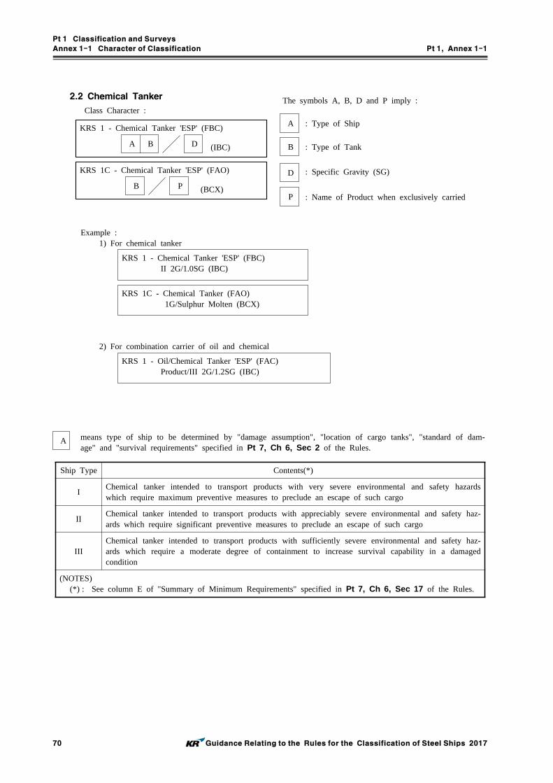
Pt 1 Classification and Surveys
Annex 1-1 Character of Classification Pt 1, Annex 1-1
70 Guidance Relating to the Rules for the Classification of Steel Ships 2017
2.2 Chemical Tanker
Class Character :
KRS 1 - Chemical Tanker 'ESP' (FBC)
A B D (IBC)
KRS 1C - Chemical Tanker 'ESP' (FAO)
B P (BCX)
The symbols A, B, D and P imply :
A : Type of Ship
B : Type of Tank
D : Specific Gravity (SG)
P : Name of Product when exclusively carried
Example :1) For chemical tanker
KRS 1 - Chemical Tanker 'ESP' (FBC) II 2G/1.0SG (IBC)
KRS 1C - Chemical Tanker (FAO) 1G/Sulphur Molten (BCX)
2) For combination carrier of oil and chemical
KRS 1 - Oil/Chemical Tanker 'ESP' (FAC) Product/III 2G/1.2SG (IBC)
A means type of ship to be determined by "damage assumption", "location of cargo tanks", "standard of dam-age" and "survival requirements" specified in Pt 7, Ch 6, Sec 2 of the Rules.
Ship Type Contents(*)
IChemical tanker intended to transport products with very severe environmental and safety hazards which require maximum preventive measures to preclude an escape of such cargo
IIChemical tanker intended to transport products with appreciably severe environmental and safety haz-ards which require significant preventive measures to preclude an escape of such cargo
IIIChemical tanker intended to transport products with sufficiently severe environmental and safety haz-ards which require a moderate degree of containment to increase survival capability in a damaged condition
(NOTES)(*) : See column E of "Summary of Minimum Requirements" specified in Pt 7, Ch 6, Sec 17 of the Rules.

Pt 1 Classification and Surveys
Annex 1-1 Character of Classification Pt 1, Annex 1-1
Guidance Relating to the Rules for the Classification of Steel Ships 2017 71
B means type of tank to be determined by "cargo containment" specified in Pt 7, Ch 6, Sec 4 and Sec 17 of the Rules, as shown in the following.
1G
2G
1P
Symbol Tank Type Contents
1 Independent Tank(1) Gravity tanks or pressure vessels(2) Tanks designed using the requirements of Pt 3, Ch 15 and Pt 5, Ch 5 of
the Rules.
2 Integral Tank(1) Self-supporting hull construction tank(2) Tank having a design pressure not greater than 0.25 bar(Max. 0.7 bar)(3) Boiling point of the cargo not to be below -10°C
G Gravity Tank(1) Independent or integral(2) Tank having a design pressure not greater than 0.7 bar
P Pressure Tank(1) Independent tank(2) Tank designed using the requirements of Pt 5, Ch 5 of the Rules(3) Tank having a design pressure greater than 0.7 bar

Pt 1 Classification and Surveys
Annex 1-1 Character of Classification Pt 1, Annex 1-1
72 Guidance Relating to the Rules for the Classification of Steel Ships 2017
2.3 Bulk Carrier or Cargo Ship
Class Character :
KRS 1 - Bulk Carrier 'ESP'
A
KRS 1C - Bulk Carrier(Double Skin) 'ESP'
A
KRS 1 - Bulk Carrier
A
KRS 1 - Cargo Ship
A
Example : 1) For ships with double bottom structures specially strengthened for the carriage of heavy cargoes
KRS 1 - Bulk Carrier 'ESP' HC
2) For ships with double bottom structures specially strengthened for the carriage of heavy cargoes as an alternate loading
KRS 1 - Bulk Carrier 'ESP' HC/E(Hold Nos. 2, 4, 6 and 8 may be empty)
3) In cases where the ship is fitted with BC-B
KRS 1 - Bulk Carrier 'ESP' BC-B
4) In cases where the ship is fitted with BC-B and the maximum cargo density is less than 3.0 tm
KRS 1 - Bulk Carrier 'ESP'
BC-B(max cargo density --- tm) 5) In cases where the ship is fitted with BC-A
KRS 1 - Bulk Carrier 'ESP' BC-A(Hold Nos. 2, 4, 6 and 8 may be empty)
6) In cases where the ship is fitted with BC-A and the maximum cargo density is less than 3.0 tm
KRS 1 - Bulk Carrier 'ESP'BC-A(Hold Nos. 2, 4, 6 and 8 may be empty
with max cargo density --- tm) 7) In cases where the ship is fitted with BC-A and the maximum cargo density is less than 3.0 tm and intended to operate in alternate block load condition.
KRS 1 - Bulk Carrier 'ESP' (CSR) BC-A(Hold Nos. 2, 4, 6 and 8 may be empty
with max cargo density --- tm) (Bock loading)
8) In cases where the ship has not been designed for loading and unloading in multiple ports in accordance with the conditions specified in Pt 7, Ch 3, 201. 5 (3) or Pt 11, Ch 4, Sec 7, [3.3] or Pt 13, Sub-part 1, Ch 4, Sec 8, [4.2.2] of the Rules
KRS 1 - Bulk Carrier 'ESP'
BC-A(or BC-B, BC-C) (no MP)

Pt 1 Classification and Surveys
Annex 1-1 Character of Classification Pt 1, Annex 1-1
Guidance Relating to the Rules for the Classification of Steel Ships 2017 73
9) In cases where the ship is complied with for unladen grab weight X equal to or greater than 20 tons ac-cording to Pt 11, Ch 12, Sec 1 or Pt 13, Sub-part 2, Ch 1, Sec 6 of the Rules
KRS 1 - Bulk Carrier 'ESP' (CSR) BC-A(or BC-B) GRAB[X]
10) Others
KRS 1 - Bulk Carrier
KRS 1C - Cargo Ship
HC

Pt 1 Classification and Surveys
Annex 1-1 Character of Classification Pt 1, Annex 1-1
74 Guidance Relating to the Rules for the Classification of Steel Ships 2017
2.4 Fishing Vessel
Class Character :
Example :KRS 1 - Fishing Vessel
Long Liner and Angling
KRS 1 - Fishing Vessel Stern Trawler
KRS 1 - Fishing Vessel (Special Feature)
2.5 Passenger Ship
KRS 1C - Passenger Ship *
Example :KRS 1C - Passenger Ship
Catamaran/Car Ferry
KRS 1C - Passenger Ship Hydrofoil
A B C *Only for submersible
KRS 1C - Passenger Ship Submersible/Leisure/Max. 70M, 2Hrs
2.6 Special Purpose Submersible
Class Character :
KRS 1C - Special Purpose Submersible
A B C D
Example : KRS 1C - Special Purpose Submersible Manned Self-Propelled/Research/Max. 70M, 1.5Hrs
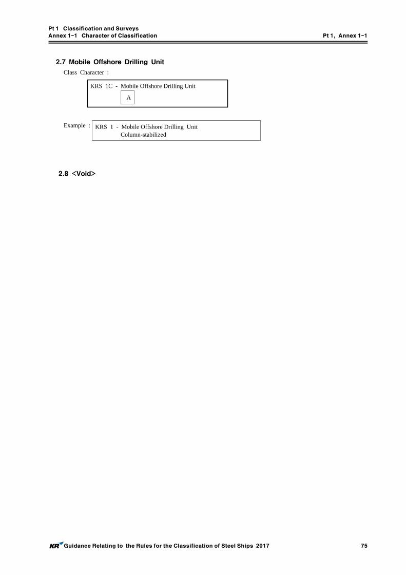
Pt 1 Classification and Surveys
Annex 1-1 Character of Classification Pt 1, Annex 1-1
Guidance Relating to the Rules for the Classification of Steel Ships 2017 75
2.7 Mobile Offshore Drilling Unit
Class Character :
KRS 1C - Mobile Offshore Drilling Unit
A
Example : KRS 1 - Mobile Offshore Drilling Unit Column-stabilized
2.8 <Void>

Pt 1 Classification and Surveys
Annex 1-1 Character of Classification Pt 1, Annex 1-1
76 Guidance Relating to the Rules for the Classification of Steel Ships 2017
2.9 Offshore Support Vessel
Class Character :
KRS 1 - Offshore Support Vessel
A B
Example :
KRS 1 - Offshore Support Vessel
Supply AH Tow HDC(30 , main deck)
KRS 1 - Offshore Support Vessel Supply AH Tow HLC(2.5SG, Tank Nos. 3 and 5)
A Special Feature Notation may be assigned as following according to the specialized functional service of the Offshore Support Vessel.
Special Feature Notation Specialized Functional Service
Supply to ships for supply service
AH to ships for anchor handling service
Tow to ships for towing service
HL to ships for heavy lift service
WTIMR to ships for wind turbine installation, maintenance and repair service
FFS1,FFS2,FFS3
to ships for fire fighting service, FFS1, FFS2 or FFS3 shall be assigned according to the minimum requirement of Table 8.1 of the Guidance for Offshore Support Vessels. Where a ship, which is comply with the requirements for FFS1, is comply with the requirements for FFS2 or FFS3 also, the class notation, Offshore Support Vessel - FFS1 FFS2 or Offshore Support Vessel - FFS1 FFS3 may be assigned.
FF
to ships not in full compliance with Ch 8 of the Guidance for Offshore Support Vessels or not specifically built for the service in-tended to be covered by Ch 8 of the Guidance for Offshore Support Vessels but equipped with some fire fighting capability in accordance with Ch 8 of the Guidance for Offshore Support Vessels.
Oil Spill Recovery to ships for oil spill recovery service
B Offshore Support Vessels built with strengthened for carrying heavy cargoes specified in accordance with Ch 3,
202. of the Guidance for Offshore Support Vessels may be assigned the relevant Special Feature Notation HDC(, Locations) or HLC(, Tanks) additionally.
(1) For example, an Offshore Support Vessel for supply service, anchor handling service and towing service,
strengthened for heavy deck cargo of 30 at main deck may be assigned the class notation Offshore Support Vessel - Supply AH Tow HDC(30 , main deck).
(2) For example, an Offshore Support Vessel for supply service, anchor handling service and towing service, strengthened for heavy liquid cargo of specific gravity 2.5 in number 3 and 5 cargo tanks may be as-signed the class notation Offshore Support Vessel - Supply AH Tow HLC(2.5SG, Tank Nos. 3 and 5).

Pt 1 Classification and Surveys
Annex 1-1 Character of Classification Pt 1, Annex 1-1
Guidance Relating to the Rules for the Classification of Steel Ships 2017 77
3.0 Special feature
Example : In cases where the ship is applied to the reduced scantling as the restriction of navigation area
and condition :
✠KRS 0 - Barge Service between Korea and Sakhalin during May and June
※ Comparison of Ice Class of the Society with Finnish-Swedish Ice Class Rules 2010 and Arctic Shipping Pollution Prevention Regulations
Ice Classof the Society
Ice Class of Finish-Swedish Ice Class Rules 2010
IA Super IA Super
IA IA
IB IB
IC IC
* II
(NOTES)*) ID class of the Society is not equal to II
class of the Finnish-Swedish Ice Class Rule, because ID class requires strengthening of forward region.
Ice Classof the Society
Ice Class of Arctic Shipping Pollution Prevention Regulations
IA Super Type A
IA Type B
IB Type C
IC Type D
ID Type D

Pt 1 Classification and Surveys
Annex 1-2 Guidance for Intact Stability Pt 1, Annex 1-2
78 Guidance Relating to the Rules for the Classification of Steel Ships 2017
Annex 1-2
Guidance for
Intact Stability

Pt 1 Classification and Surveys
Annex 1-2 Guidance for Intact Stability Pt 1, Annex 1-2
Guidance Relating to the Rules for the Classification of Steel Ships 2017 79
APPLICATION OF
"GUIDANCE FOR INTACT STABILITY"
Unless expressly specified otherwise, the requirements in the Guidance apply to ships for which contracts for construction are signed on or after 1 July 2015.

Pt 1 Classification and Surveys
Annex 1-2 Guidance for Intact Stability Pt 1, Annex 1-2
Guidance Relating to the Rules for the Classification of Steel Ships 2017 81
CONTENTS
INTRODUCTION ···················································································································80
1. Purpose ···························································································································· 80
2. Definition ························································································································ 80
PART A MANDATORY CRITERIA ··············································································83
Chapter 1 General ·············································································································· 83
1.1 Application ···················································································································· 83
Chapter 2 General Criteria ······························································································· 84
2.1 General ·························································································································· 84
2.2 Criteria regarding righting lever curve properties ······················································ 84
2.3 Severe wind and rolling criterion(weather criterion) ················································· 84
Chapter 3 Special Criteria for Certain Types of Ships ············································ 88
3.1 Passenger ships ············································································································· 88
3.2 Oil tankers of 5,000 and above ··········································································· 88
3.3 Cargo ships carrying timber deck cargoes ································································· 88
3.4 Cargo ships carrying grain in bulk ············································································ 89
3.5 High-speed craft ··········································································································· 89
PART B RECOMMENDATIONS FOR CERTAIN TYPES OF SHIPS
AND ADDITIONAL GUIDELINES ·····················································90
Chapter 1 General ·············································································································· 90
1.1 Purpose ·························································································································· 90
1.2 Application ···················································································································· 90
Chapter 2 Recommended design criteria for certain Types of Ships ················· 91
2.1 Fishing vessels ·············································································································· 91
2.2 Pontoons ························································································································ 92
2.3 Containerships greater than 100 in length ····························································· 93
2.4 Offshore supply vessels ······························································································· 95
2.5 Special purpose ships ··································································································· 95
2.6 Mobile offshore drilling units(MODUs) ····································································· 95
Chapter 3 Guidance in Preparing Stability Information ············································ 96
3.1 Effect of free surfaces of liquids in tanks ································································ 96
3.2 Permanent ballast ·········································································································· 97
3.3 Assessment of compliance with stability criteria ······················································· 97
3.4 Standard conditions of loading to be examined ························································ 97
3.5 Calculation of stability curves ····················································································· 99
3.6 Stability booklet ·········································································································· 100

Pt 1 Classification and Surveys
Annex 1-2 Guidance for Intact Stability Pt 1, Annex 1-2
82 Guidance Relating to the Rules for the Classification of Steel Ships 2017
INTRODUCTION
1. Purpose
1.1 The purpose of the Guidance is to present mandatory and recommendatory stability criteria and other measures for ensuring the safe operation of ships, to minimize the risk to such ships, to the personnel on board and to the environment. This INTRODUCTION and Pt A of the Guidance ad-dress the mandatory criteria and Pt B contains recommendations and additional guidelines.
1.2 This Guidance contains intact stability criteria for the following types of ships and other marine vehicles of 24 in length and above, unless otherwise stated:.1 cargo ships;.2 cargo ships carrying timber deck cargoes;.3 passenger ships;.4 fishing vessels;.5 special purpose ships;.6 offshore supply vessels;.7 mobile offshore drilling units;.8 pontoons; and.9 cargo ships carrying containers on deck and containerships.
1.3 Administrations may impose additional requirements regarding the design aspects of ships of novel design or ships not otherwise covered by the Guidance.
2. Definitions
For the purpose of this Guidance the definitions given hereunder shall apply. For terms used, but not defined in this Guidance, the definitions as given in the 1974 SOLAS Convention, as amended, shall apply.
2.1 Administration means the Government of the State whose flag the ship is entitled to fly.
2.2 Passenger ship is a ship which carries more than twelve passengers as defined in regulation I/2 of the 1974 SOLAS Convention, as amended.
2.3 Cargo ship is any ship which is not a passenger ship, a ship of war and troopship, a ship which is not propelled by mechanical means, a wooden ship of primitive build, a fishing vessel or a mo-bile offshore drilling unit.
2.4 Oil tanker means a ship constructed or adapted primarily to carry oil in bulk in its cargo spaces and includes combination carriers and any chemical tanker as defined in Annex II of the MARPOL Convention when it is carrying a cargo or part cargo of oil in bulk.2.4.1 Combination carrier means a ship designed to carry either oil or solid cargoes in bulk.2.4.2 Crude oil tanker means an oil tanker engaged in the trade of carrying crude oil.2.4.3 Product carrier means an oil tanker engaged in the trade of carrying oil other than crude oil.
2.5 Fishing vessel is a vessel used for catching fish, whales, seals, walrus or other living resources of the sea.
2.6 Special purpose ship has the same definition as in the Code of Safety for Special Purpose Ships, 2008(IMO Res.MSC.266(84)).
2.7 Offshore supply vessel means a vessel which is engaged primarily in the transport of stores, mate-rials and equipment to offshore installations and designed with accommodation and bridge erections in the forward part of the vessel and an exposed cargo deck in the after part for the handling of cargo at sea.
2.8 Mobile offshore drilling unit(MODU or unit) is a ship capable of engaging in drilling operations for the exploration or exploitation of resources beneath the sea-bed such as liquid or gaseous hy-drocarbons, sulphur or salt.2.8.1 Column-stabilized unit is a unit with the main deck connected to the underwater hull or foot-
ings by columns or caissons.2.8.2 Surface unit is a unit with a ship- or barge-type displacement hull of single or multiple hull
construction intended for operation in the floating condition.

Pt 1 Classification and Surveys
Annex 1-2 Guidance for Intact Stability Pt 1, Annex 1-2
Guidance Relating to the Rules for the Classification of Steel Ships 2017 83
2.8.3 Self-elevating unit is a unit with moveable legs capable of raising its hull above the surface of the sea.
2.8.4 Coastal State means the Government of the State exercising administrative control over the drilling operations of the unit.
2.8.5 Mode of operation means a condition or manner in which a unit may operate or function while on location or in transit. The modes of operation of a unit include the following:.1 operating conditions means conditions wherein a unit is on location for the purpose of con-
ducting drilling operations, and combined environmental and operational loadings are within the appropriate design limits established for such operations. The unit may be either afloat or supported on the sea-bed, as applicable;
.2 severe storm conditions means conditions wherein a unit may be subjected to the most severe environmental loadings for which the unit is designed. Drilling operations are assumed to have been discontinued due to the severity of the environmental loadings, the unit may be either afloat or supported on the sea-bed, as applicable; and
.3 transit conditions means conditions wherein a unit is moving from one geographical location to another.
2.9 High-speed craft(HSC)* is a craft capable of a maximum speed, in metres per second(), equal to or exceeding:* : The Code of Safety for High-Speed Craft, 2000(2000 HSC Code) has been developed following
a thorough revision of the Code of Safety for High-Speed Craft, 1994(1994 HSC Code) which was derived from the previous Code of Safety for Dynamically Supported Craft(DSC Code) adopted by IMO in 1977, recognizing that safety levels can be significantly enhanced by the infrastructure associated with regular service on a particular route, whereas the conventional ship safety philosophy relies on the ship being self-sustaining with all necessary emergency equipment being carried on board.
∇
where:
∇ = volume of displacement corresponding to the design waterline ().
2.10 Containership means a ship which is used primarily for the transport of marine containers.
2.11 Freeboard is the distance between the assigned load line and freeboard deck**.** : For the purposes of application of chapters I and II of Annex I of the International
Convention on Load Lines, 1966 or the Protocol of 1988 as amended, as applicable to open-top containerships, "freeboard deck" is the freeboard deck according to the International Convention on Load Lines, 1966 or the Protocol of 1988 as amended, as applicable as if hatch covers are fitted on top of the hatch cargo coamings.
2.12 Length of ship
The length should be taken as 96% of the total length on a waterline at 85% of the least moulded depth measured from the top of the keel, or as the length from the fore side of the stem to the axis of the rudder stock on the waterline, if that be greater. In ships designed with a rake of keel the waterline on which this length is measured should be parallel to the designed waterline.
2.13 Moulded breadth is the maximum breadth of the ship measured amidships to the moulded line of the frame in a ship with a metal shell and to the outer surface of the hull in a ship with a shell of any other material.
2.14 Moulded depth is the vertical distance measured from the top of the keel to the top of the free-board deck beam at side. In wood and composite ships, the distance is measured from the lower edge of the keel rabbet. Where the form at the lower part of the midship section is of a hollow character, or where thick garboards are fitted, the distance is measured from the point where the line of the flat of the bottom continued inwards cuts the side of the keel. In ships having rounded gunwales, the moulded depth should be measured to the point of intersection of the moulded lines of the deck and side shell plating, the lines extending as though the gunwale were of angular design. Where the freeboard deck is stepped and the raised part of the deck extends over the point at which the moulded depth is to be determined, the moulded depth should be measured to a line

Pt 1 Classification and Surveys
Annex 1-2 Guidance for Intact Stability Pt 1, Annex 1-2
84 Guidance Relating to the Rules for the Classification of Steel Ships 2017
of reference extending from the lower part of the deck along a line parallel with the raised part.
2.15 Near-coastal voyage means a voyage in the vicinity of the coast of a State as defined by the Administration of that State.
2.16 Pontoon is considered to be normally:.1 non self-propelled;.2 unmanned;.3 carrying only deck cargo;.4 having a block coefficient of 0.9 or greater;.5 having a breadth/depth ratio of greater than 3; and.6 having no hatchways in the deck except small manholes closed with gasketed covers.
2.17 Timber means sawn wood or lumber, cants, logs, poles, pulpwood and all other types of timber in loose or packaged forms. The term does not include wood pulp or similar cargo.
2.18 Timber deck cargo means a cargo of timber carried on an uncovered part of a freeboard or su-perstructure deck. The term does not include wood pulp or similar cargo.** : Refer to regulation 42(1) of the International Convention on Load Lines, 1966 or the Protocol
of 1988 as amended, as applicable.2.19 Timber load line means a special load line assigned to ships complying with certain conditions
related to their construction set out in the International Convention on Load Lines and used when the cargo complies with the stowage and securing conditions of the Code of Safe Practice for Ships Carrying Timber Deck Cargoes, 1991(IMO Res.A.715(17)).
2.20 Certification of the inclining test weights is the verification of the weight marked on a test weight. Test weights should be certified using a certificated scale. The weighing should be per-formed close enough in time to the inclining test to ensure the measured weight is accurate.
2.21 Draught is the vertical distance from the moulded baseline to the waterline.
2.22 The inclining test involves moving a series of known weights, normally in the transverse direc-tion, and then measuring the resulting change in the equilibrium heel angle of the ship. By using this information and applying basic naval architecture principles, the ship's vertical centre of grav-ity() is determined.
2.23 Lightship condition is a ship complete in all respects, but without consumables, stores, cargo, crew and effects, and without any liquids on board except that machinery and piping fluids, such as lubricants and hydraulics, are at operating levels. But, the weight of mediums on board for the fixed fire-fighting system (e.g. freshwater, CO2, dry powder, foam concentrate, etc.) shall be in-cluded in the lightweight and lightship conditions. (2017)
2.24 A lightweight survey involves taking an audit of all items which should be added, deducted or relocated on the ship at the time of the inclining test so that the observed condition of the ship can be adjusted to the lightship condition. The mass, longitudinal, transverse and vertical location of each item should be accurately determined and recorded. Using this information, the static water-line of the ship at the time of the inclining test as determined from measuring the freeboard or verified draught marks of the ship, the ship's hydrostatic data, and the sea water density, the light-ship displacement and longitudinal centre of gravity() can be obtained. The transverse centre of gravity() may also be determined for mobile offshore drilling units(MODUs) and other ships which are asymmetrical about the centreline or whose internal arrangement or outfitting is such that an inherent list may develop from off-centre mass.
2.25 An in-service inclining test means an inclining test which is performed in order to verify the pre-calculated and the deadweight's centre of gravity of an actual loading condition.
2.26 A stability instrument is an instrument installed on board a particular ship by means of which it can be ascertained that stability requirements specified for the ship in the Stability Booklet are met in any operational loading condition. A Stability Instrument comprises hardware and software.

Pt 1 Classification and Surveys
Annex 1-2 Guidance for Intact Stability Pt 1, Annex 1-2
Guidance Relating to the Rules for the Classification of Steel Ships 2017 85
PART A MANDATORY CRITERIA
CHAPTER 1 GENERAL
1.1 ApplicationThis Guidance applies to ships engaged on international voyages, and ships not engaged on interna-tional voyages are to be compliance with the relevant local regulations of the flag states in which ships are flying.1.1.1 The criteria stated under Ch 2 of this Part present a set of minimum requirements that shall
apply to cargo* and passenger ships of 24 in length and over.* For containerships of 100 in length and over, provisions of 2.3 of Pt B may be applied as
an alternative to the application of 2.2 of this Part. Offshore supply vessels and special pur-pose ships are not required to comply with provisions of 2.3 of Pt A. For offshore supply vessels, provisions of 2.4 of Pt B may be applied as an alternative to the application of 2.2 of this part. For special purpose ships, provisions of 2.5 of Pt B may be applied as an alter-native to the application of 2.2 of this Part.
1.1.2 The criteria stated under Ch 3 are special criteria for certain types of ships. For the purpose of Pt A the definitions given in the INTRODUCTION apply.
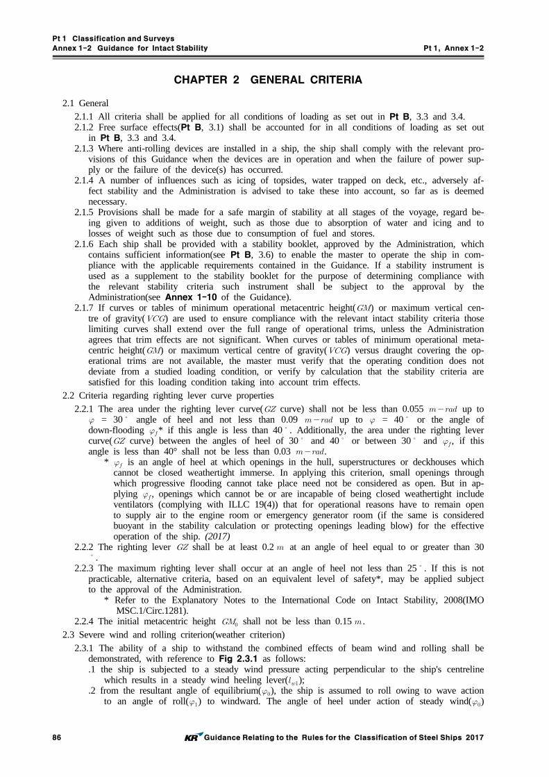
Pt 1 Classification and Surveys
Annex 1-2 Guidance for Intact Stability Pt 1, Annex 1-2
86 Guidance Relating to the Rules for the Classification of Steel Ships 2017
CHAPTER 2 GENERAL CRITERIA
2.1 General2.1.1 All criteria shall be applied for all conditions of loading as set out in Pt B, 3.3 and 3.4.2.1.2 Free surface effects(Pt B, 3.1) shall be accounted for in all conditions of loading as set out
in Pt B, 3.3 and 3.4.2.1.3 Where anti-rolling devices are installed in a ship, the ship shall comply with the relevant pro-
visions of this Guidance when the devices are in operation and when the failure of power sup-ply or the failure of the device(s) has occurred.
2.1.4 A number of influences such as icing of topsides, water trapped on deck, etc., adversely af-fect stability and the Administration is advised to take these into account, so far as is deemed necessary.
2.1.5 Provisions shall be made for a safe margin of stability at all stages of the voyage, regard be-ing given to additions of weight, such as those due to absorption of water and icing and to losses of weight such as those due to consumption of fuel and stores.
2.1.6 Each ship shall be provided with a stability booklet, approved by the Administration, which contains sufficient information(see Pt B, 3.6) to enable the master to operate the ship in com-pliance with the applicable requirements contained in the Guidance. If a stability instrument is used as a supplement to the stability booklet for the purpose of determining compliance with the relevant stability criteria such instrument shall be subject to the approval by the Administration(see Annex 1-10 of the Guidance).
2.1.7 If curves or tables of minimum operational metacentric height() or maximum vertical cen-tre of gravity() are used to ensure compliance with the relevant intact stability criteria those limiting curves shall extend over the full range of operational trims, unless the Administration agrees that trim effects are not significant. When curves or tables of minimum operational meta-centric height() or maximum vertical centre of gravity() versus draught covering the op-erational trims are not available, the master must verify that the operating condition does not deviate from a studied loading condition, or verify by calculation that the stability criteria are satisfied for this loading condition taking into account trim effects.
2.2 Criteria regarding righting lever curve properties2.2.1 The area under the righting lever curve( curve) shall not be less than 0.055 up to = 30 angle of heel and not less than 0.09 up to = 40 or the angle of down-flooding * if this angle is less than 40. Additionally, the area under the righting lever curve( curve) between the angles of heel of 30 and 40 or between 30 and , if this angle is less than 40° shall not be less than 0.03 .
* is an angle of heel at which openings in the hull, superstructures or deckhouses which cannot be closed weathertight immerse. In applying this criterion, small openings through which progressive flooding cannot take place need not be considered as open. But in ap-plying , openings which cannot be or are incapable of being closed weathertight include ventilators (complying with ILLC 19(4)) that for operational reasons have to remain open to supply air to the engine room or emergency generator room (if the same is considered buoyant in the stability calculation or protecting openings leading blow) for the effective operation of the ship. (2017)
2.2.2 The righting lever shall be at least 0.2 at an angle of heel equal to or greater than 30.
2.2.3 The maximum righting lever shall occur at an angle of heel not less than 25. If this is not practicable, alternative criteria, based on an equivalent level of safety*, may be applied subject to the approval of the Administration.
* Refer to the Explanatory Notes to the International Code on Intact Stability, 2008(IMO MSC.1/Circ.1281).
2.2.4 The initial metacentric height shall not be less than 0.15 .2.3 Severe wind and rolling criterion(weather criterion)
2.3.1 The ability of a ship to withstand the combined effects of beam wind and rolling shall be demonstrated, with reference to Fig 2.3.1 as follows:.1 the ship is subjected to a steady wind pressure acting perpendicular to the ship's centreline
which results in a steady wind heeling lever();.2 from the resultant angle of equilibrium(), the ship is assumed to roll owing to wave action
to an angle of roll() to windward. The angle of heel under action of steady wind()

Pt 1 Classification and Surveys
Annex 1-2 Guidance for Intact Stability Pt 1, Annex 1-2
Guidance Relating to the Rules for the Classification of Steel Ships 2017 87
should not exceed 16 or 80% of the angle of deck edge immersion, whichever is less;.3 the ship is then subjected to a gust wind pressure which results in a gust wind heeling lev-
er(); and.4 under these circumstances, area shall be equal to or greater than area , as indicated in Fig 2.3.1 below:
Fig 2.3.1 Severe wind and rolling
where the angles in Fig 2.3.1 are defined as follows:
= angle of heel under action of steady wind
= angle of roll to windward due to wave action(see 2.3.4)
= angle of down-flooding() or 50 or , whichever is less,
where:
= angle of heel at which openings in the hull, superstructures or deckhouses which
cannot be closed weathertight immerse. In applying this criterion, small openings
through which progressive flooding cannot take place need not be considered as
open
= angle of second intercept between wind heeling lever and curves.
2.3.2 The wind heeling levers and referred to in 2.3.1.1 and 2.3.1.3 are constant values at all angles of inclination and shall be calculated as follows:
∆
and
where:
= wind pressure of 504 . The value of used for ships in restricted service area may
be reduced subject to the approval of the Administration
= projected lateral area of the portion of the ship and deck cargo above the waterline
(m) = vertical distance from the centre of to the centre of the underwater lateral area or
approximately to a point at one half the mean draught ()
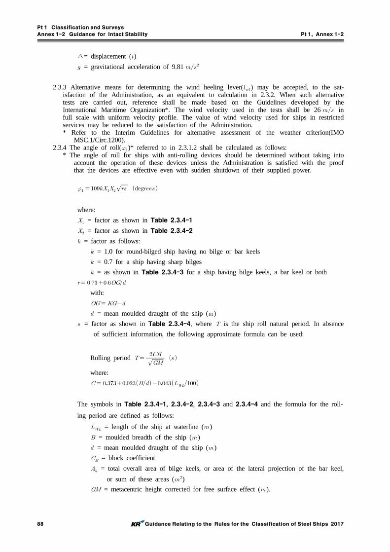
Pt 1 Classification and Surveys
Annex 1-2 Guidance for Intact Stability Pt 1, Annex 1-2
88 Guidance Relating to the Rules for the Classification of Steel Ships 2017
∆= displacement ()
= gravitational acceleration of 9.81
2.3.3 Alternative means for determining the wind heeling lever() may be accepted, to the sat-isfaction of the Administration, as an equivalent to calculation in 2.3.2. When such alternative tests are carried out, reference shall be made based on the Guidelines developed by the International Maritime Organization*. The wind velocity used in the tests shall be 26 in full scale with uniform velocity profile. The value of wind velocity used for ships in restricted services may be reduced to the satisfaction of the Administration.* Refer to the Interim Guidelines for alternative assessment of the weather criterion(IMO
MSC.1/Circ.1200).2.3.4 The angle of roll()* referred to in 2.3.1.2 shall be calculated as follows:
* The angle of roll for ships with anti-rolling devices should be determined without taking into account the operation of these devices unless the Administration is satisfied with the proof that the devices are effective even with sudden shutdown of their supplied power.
deg
where:
= factor as shown in Table 2.3.4-1
= factor as shown in Table 2.3.4-2
= factor as follows:
= 1.0 for round-bilged ship having no bilge or bar keels
= 0.7 for a ship having sharp bilges
= as shown in Table 2.3.4-3 for a ship having bilge keels, a bar keel or both
with:
= mean moulded draught of the ship (m)
= factor as shown in Table 2.3.4-4, where is the ship roll natural period. In absence
of sufficient information, the following approximate formula can be used:
Rolling period
where:
The symbols in Table 2.3.4-1, 2.3.4-2, 2.3.4-3 and 2.3.4-4 and the formula for the roll-
ing period are defined as follows:
= length of the ship at waterline ()
= moulded breadth of the ship ()
= mean moulded draught of the ship ()
= block coefficient
= total overall area of bilge keels, or area of the lateral projection of the bar keel,
or sum of these areas ()
= metacentric height corrected for free surface effect ().

Pt 1 Classification and Surveys
Annex 1-2 Guidance for Intact Stability Pt 1, Annex 1-2
Guidance Relating to the Rules for the Classification of Steel Ships 2017 89
Table 2.3.4-1 Values of factor
≤2.4 2.5 2.6 2.7 2.8 2.9 3.0 3.1 3.2 3.4 ≥3.5
1.0 0.98 0.96 0.95 0.93 0.91 0.90 0.88 0.86 0.82 0.80
Table 2.3.4-2 Values of factor
≤0.45 0.50 0.55 0.60 0.65 ≥0.70
0.75 0.82 0.89 0.95 0.97 1.00
Table 2.3.4-3 Values of factor
×
×0 1.0 1.5 2.0 2.5 3.0 3.5 ≥4.0
1.0 0.98 0.95 0.88 0.79 0.74 0.72 0.70
Table 2.3.4-4 Values of factor
≤6 7 8 12 14 16 18 ≥20
0.100 0.098 0.093 0.065 0.053 0.044 0.038 0.035
(Intermediate values in these tables shall be obtained by linear interpolation)
2.3.5 The tables and formulae described in 2.3.4 are based on data from ships having:.1 smaller than 3.5;.2 between - 0.3 and 0.5; and.3 smaller than 20 .For ships with parameters outside of the above limits the angle of roll() may be determined with model experiments of a subject ship with the procedure described in IMO MSC.1/Circ.1200 as the alternative. In addition, the Administration may accept such alternative determinations for any ship, if deemed appropriate.

Pt 1 Classification and Surveys
Annex 1-2 Guidance for Intact Stability Pt 1, Annex 1-2
90 Guidance Relating to the Rules for the Classification of Steel Ships 2017
CHAPTER 3 SPECIAL CRITERIA FOR CERTAIN TYPES OF SHIPS
3.1 Passenger ships
Passenger ships shall comply with the requirements of 2.2 and 2.3.3.1.1 In addition, the angle of heel on account of crowding of passengers to one side as defined
below shall not exceed 10.3.1.1.1 A minimum weight of 75 shall be assumed for each passenger except that this value
may be increased subject to the approval of the Administration. In addition, the mass and distribution of the luggage shall be approved by the Administration.
3.1.1.2 The height of the centre of gravity for passengers shall be assumed equal to:.1 1 above deck level for passengers standing upright. Account may be taken, if neces-
sary, of camber and sheer of deck; and.2 0.3 above the seat in respect of seated passengers.
3.1.1.3 Passengers and luggage shall be considered to be in the spaces normally at their dis-posal, when assessing compliance with the criteria given in 2.2.1 to 2.2.4.
3.1.1.4 Passengers without luggage shall be considered as distributed to produce the most un-favourable combination of passenger heeling moment and/or initial metacentric height, which may be obtained in practice, when assessing compliance with the criteria given in 3.1.1 and 3.1.2, respectively. In this connection, a value higher than four persons per square metre is not necessary.
3.1.2 In addition, the angle of heel on account of turning shall not exceed 10 when calculated using the following formula:
∆
where:
= heeling moment ()
= service speed ()
= length of ship at waterline ()
∆= displacement ()
= mean draught ()
= height of centre of gravity above baseline ().
3.2 Oil tankers of 5,000 and aboveOil tankers, as defined in 2(Definitions) of the INTRODUCTION, shall comply with regulation 27 of Annex I to MARPOL 73/78.
3.3 Cargo ships carrying timber deck cargoesCargo ships carrying timber deck cargoes shall comply with the requirements of 2.2 and 2.3 unless the Administration is satisfied with the application of alternative provision 3.3.2.3.3.1 Scope
The provisions given hereunder apply to all ships of 24 in length and over engaged in the carriage of timber deck cargoes. Ships that are provided with, and make use of, their timber load line shall also comply with the requirements of regulations 41 to 45 of the 1966 Load Line Convention.

Pt 1 Classification and Surveys
Annex 1-2 Guidance for Intact Stability Pt 1, Annex 1-2
Guidance Relating to the Rules for the Classification of Steel Ships 2017 91
3.3.2 Alternative stability criteriaFor ships loaded with timber deck cargoes and provided that the cargo extends longitudinally between superstructures(where there is no limiting superstructure at the after end, the timber deck cargo shall extend at least to the after end of the aftermost hatchway)* transversely for the full beam of ship, after due allowance for a rounded gunwale, not exceeding 4% of the breadth of the ship and/or securing the supporting uprights and which remains securely fixed at large angles of heel may be:* Refer to regulation 44(2) of the International Convention on Load Lines, 1966 or the Protocol of 1988 relating thereto, as amended, as applicable.3.3.2.1 The area under the righting lever curve( curve) shall not be less than 0.08
up to = 40 or the angle of flooding if this angle is less than 40.3.3.2.2 The maximum value of the righting lever() shall be at least 0.25 .3.3.2.3 At all times during a voyage, the metacentric height shall not be less than 0.1 ,
taking into account the absorption of water by the deck cargo and/or ice accretion on the exposed surfaces.
3.3.2.4 When determining the ability of the ship to withstand the combined effects of beam wind and rolling according to 2.3, the 16 limiting angle of heel under action of steady wind shall be complied with, but the additional criterion of 80% of the angle of deck edge immersion may be ignored.
3.4 Cargo ships carrying grain in bulkThe intact stability of ships engaged in the carriage of grain shall comply with the requirements of the International Code for the Safe Carriage of Grain in Bulk adopted by IMO Res.MSC.23(59).** Refer to part C of chapter VI of the 1974 SOLAS Convention as amended.
3.5 High-speed craftHigh-speed craft, as defined in 2(Definitions) of the INTRODUCTION, constructed on or after 1 January 1996 but before 1 July 2002, to which chapter X of the 1974 SOLAS Convention applies, shall comply with stability requirements of the 1994 HSC Code(IMO Res.MSC.36(63)). Any high-speed craft to which chapter X of the 1974 SOLAS Convention applies, irrespective of its date of construction, which has undergone repairs, alterations or modifications of a major character; and a high-speed craft constructed on or after 1 July 2002, shall comply with stability requirements of the 2000 HSC Code(IMO Res.MSC.97(73)).

Pt 1 Classification and Surveys
Annex 1-2 Guidance for Intact Stability Pt 1, Annex 1-2
92 Guidance Relating to the Rules for the Classification of Steel Ships 2017
PART BRECOMMENDATIONS FOR CERTAIN TYPES OF SHIPS AND
ADDITIONAL GUIDELINES
CHAPTER 1 GENERAL
1.1 PurposeThe purpose of this part of the Guidance is to:.1 recommend stability criteria and other measures for ensuring the safe operation of certain types
of ships to minimize the risk to such ships, to the personnel on board and to the environment.1.2 Application
1.2.1 This part of the Guidance contains recommended intact stability criteria for certain types of ships and other marine vehicles not included in Pt A or intended to supplement those of Pt A in particular cases regarding size or operation.
1.2.2 Administrations may impose additional requirements regarding the design aspects of ships of novel design or ships not otherwise covered by the Guidance.
1.2.3 The criteria stated in this part should give as a guidance if no national requirements are applied.

Pt 1 Classification and Surveys
Annex 1-2 Guidance for Intact Stability Pt 1, Annex 1-2
Guidance Relating to the Rules for the Classification of Steel Ships 2017 93
CHAPTER 2 RECOMMENDED DESIGN CRITERIA FOR CERTAIN TYPES OF SHIPS
2.1 Fishing vessels2.1.1 ScopeThe provisions given hereunder apply to decked seagoing fishing vessels as defined in 2(Definitions) of the INTRODUCTION. The stability criteria given in 2.1.2 and 2.1.3 below should be complied with for all conditions of loading as specified in 3.4.1.6, unless the Administration is satisfied that operating experience justifies departures therefrom.2.1.2 Recommended general criteria*
* Refer to regulation III/2 of the 1993 Torremolinos Protocol.2.1.2.1 The general intact stability criteria given in Pt A, 2.2.1 to 2.2.3 should apply to fishing
vessels having a length of 24 and over, with the exception of requirements on the initial metacentric height (Pt A, 2.2.4), which, for fishing vessels, should not be less than 0.35 for single-deck vessels. In vessels with complete superstructure or vessels of 70 in length and over the metacentric height may be reduced to the satisfaction of the Administration but in no case should be less than 0.15 .
2.1.2.2 The adoption by individual countries of simplified criteria which apply such basic stabil-ity values to their own types and classes of vessels is recognized as a practical and val-uable method of economically judging the stability.
2.1.2.3 Where arrangements other than bilge keels are provided to limit the angle of roll, the Administration should be satisfied that the stability criteria referred to in 2.1.2.1 are main-tained in all operating conditions.
2.1.3 Severe wind and rolling criterion(weather criterion) for fishing vessels2.1.3.1 The Administration may apply the provisions of Pt A, 2.3 to fishing vessels of 45
length and over.2.1.3.2 For fishing vessels in the length range between 24 and 45 , the Administration may
apply the provisions of Pt A, 2.3. Alternatively the values of wind pressure(see Pt A, 2.3.2) may be taken from the following table:
( ) 1 2 3 4 5 6 and over
() 316 386 429 460 485 504
where is the vertical distance from the centre of the projected vertical area of the vessel above the waterline, to the waterline.
2.1.4 Recommendation for an interim simplified stability criterion for decked fishing vessels under 30 in length2.1.4.1 For decked vessels with a length less than 30 , the following approximate formula for
the minimum metacentric.
where:
is the length of the vessel on the waterline in maximum load condition ()
is the actual length of enclosed superstructure extending from side to side of the
vessel ()
is the extreme breadth of the vessel on the waterline in maximum load condition
()
is the depth of the vessel measured vertically amidships from the base line to the
top of the upper deck at side ()
is the smallest freeboard measured vertically from the top of the upper deck at side
to the actual waterline ().

Pt 1 Classification and Surveys
Annex 1-2 Guidance for Intact Stability Pt 1, Annex 1-2
94 Guidance Relating to the Rules for the Classification of Steel Ships 2017
The formula is applicable for vessels having:
.1 between 0.02 and 0.2;
.2 smaller than 0.6;
.3 between 1.75 and 2.15;
.4 sheer fore and aft at least equal to or exceeding the standard sheer prescribed in
regulation 38(8) of the International Convention on Load Lines, 1966 or the
Protocol of 1988 as amended, as applicable; and
.5 height of superstructure included in the calculation is not less than 1.8 .
For ships with parameters outside the above limits the formula should be applied with
special care.
2.1.4.2 The above formula is not intended as a replacement for the basic criteria given in 2.1.2 and 2.1.3 but is to be used only if circumstances are such that cross curves of stability, curve and subsequent curves are not and cannot be made available for judging a particular vessel's stability.
2.1.4.3 The calculated value of , should be compared with actual values of the vessel in all loading conditions. If an inclining experiment based on estimated displacement, or an-other approximate method of determining the actual is used, a safety margin should be added to the calculated min .
2.2 Pontoons2.2.1 Application
The provisions given hereunder apply to seagoing pontoons. A pontoon is considered to be nor-mally:.1 non self-propelled;.2 unmanned;.3 carrying only deck cargo;.4 having a block coefficient of 0.9 or greater;.5 having a breadth/depth ratio of greater than 3; and.6 having no hatchways in the deck except small manholes closed with gasketed covers.
2.2.2 Stability drawings and calculationsThe following information is typical of that required to be submitted to the Administration for approval:.1 lines drawing;.2 hydrostatic curves;.3 cross curves of stability;.4 report of draught and density readings and calculation of lightship displacement and longi-
tudinal centre of gravity;.5 statement of justification of assumed vertical centre of gravity; and.6 simplified stability guidance such as a loading diagram, so that the pontoon may be loaded
in compliance with the stability criteria.2.2.3 Concerning the performance of calculations
The following guidance is suggested:.1 no account should be taken of the buoyancy of deck cargo except buoyancy credit for ad-
equately secured timber;.2 consideration should be given to such factors as water absorption(e.g., timber), trapped water
in cargo(e.g., pipes) and ice accretion;.3 in performing wind heel calculations:
.3.1 the wind pressure should be constant and for general operations be considered to act on a solid mass extending over the length of the cargo deck and to an assumed height above the deck;
.3.2 the centre of gravity of the cargo should be assumed at a point mid-height of the car-go; and
.3.3 the wind lever should be taken from the centre of the deck cargo to a point at one half the mean draught;

Pt 1 Classification and Surveys
Annex 1-2 Guidance for Intact Stability Pt 1, Annex 1-2
Guidance Relating to the Rules for the Classification of Steel Ships 2017 95
.4 calculations should be performed covering the full range of operating draughts; and
.5 the down-flooding angle should be taken as the angle at which an opening through which progressive flooding may take place is immersed. This would not be an opening closed by a watertight manhole cover or a vent fitted with an automatic closure.
2.2.4 Intact stability criteria2.2.4.1 The area under the righting lever curve up to the angle of maximum righting lever
should not be less than 0.08 .2.2.4.2 The static angle of heel due to a uniformly distributed wind load of 540 (wind speed
30 ) should of wind heeling moment is measured from the centroid of the windage area to half the draught.
2.2.4.3 The minimum range of stability should be:for ≤ : 20;for ≥ : 15;for intermediate length: by interpolation.
2.3 Containerships greater than 100 in length2.3.1 Application*
* Since the criteria in this section were empirically developed with the data of containerships less than 200 in length, they should be applied to ships beyond such limits with special care.These requirements apply to containerships greater than 100 in length as defined in 2(Definitions) of the INTRODUCTION. They may also be applied to other cargo ships in this length range with considerable flare or large water plane areas. The Administration may apply the following criteria instead of those in Pt A, 2.2.
2.3.2 Intact stability2.3.2.1 The area under the righting lever curve( curve) should not be less than up to = 30 angle of heel, and not less than up to = 40 or the angle of flooding (as defined in Pt A, 2.2) if this angle is less than 40.
2.3.2.2 Additionally, the area under the righting lever curve( curve) between the angles of heel of 30 and 40 or between 30° and , if this angle is less than 40, should not be less than .
2.3.2.3 The righting lever should be at least at an angle of heel equal or great-er than 30.
2.3.2.4 The maximum righting lever should be at least .2.3.2.5 The total area under the righting lever curve( curve) up to the angle of flooding
should not be less than .2.3.2.6 In the above criteria the form factor should be calculated using the following formula
and Fig 2.3-1:
′
where:
= mean draught ()
′ = moulded depth of the ship, corrected for defined parts of volumes within the
hatch coamings according to the following formula:
′
∑ , as defined in Fig 2.3-1;

Pt 1 Classification and Surveys
Annex 1-2 Guidance for Intact Stability Pt 1, Annex 1-2
96 Guidance Relating to the Rules for the Classification of Steel Ships 2017
where,
= moulded depth of the ship ();
= moulded breadth of the ship ();
= length of each hatch coaming within forward and aft from amidships
()(see Fig 2.3-1);
= mean width of hatch coamings within forward and aft from amidships
()(see Fig 2.3-1);
= mean height of hatch coamings within forward and aft from amidships
(m)(see Fig 2.3-1);
= length of the ship ();
= height of the centre of mass above base, corrected for free surface effect, not be
taken as less than ();
= block coefficient;
= water plane coefficient;
= breadth of the ship on the waterline ();
= breadth of the ship on the waterline at half mean draught ().
Fig 2.3-1
The shaded areas in Fig 2.3-1 represent partial volumes within the hatch coamings consid-ered contributing to resistance against capsizing at large heeling angles when the ship is on a wave crest.
2.3.2.7 The use of electronic loading and stability instrument is encouraged in determining the ship's trim and stability during different operational conditions.

Pt 1 Classification and Surveys
Annex 1-2 Guidance for Intact Stability Pt 1, Annex 1-2
Guidance Relating to the Rules for the Classification of Steel Ships 2017 97
2.4 Offshore supply vessels2.4.1 Application
2.4.1.1 The provisions given hereunder apply to offshore supply vessels, as defined in 2(Definitions) of the INTRODUCTION, of 24 in length and over. The alternative stability criteria contained in 2.4.2 apply to vessels of not more than 100 in length.
2.4.2 Stability criteria2.4.2.1 The stability criteria given in Pt A, 2.2 should apply to all offshore supply vessels ex-
cept those having characteristics which render compliance with Pt A, 2.2 impracticable.2.4.2.2 The following equivalent criteria should be applied where a vessel's characteristics render
compliance with Pt A, 2.2 impracticable:.1 the area under the curve of righting levers( curve) should not be less than 0.07 up to an angle of 15 when the maximum righting lever() occurs at 15 and 0.055 up to an angle of 30° when the maximum righting lever() occurs at 30 or above. Where the maximum righting lever() occurs at angles of between 15 and 30, the corresponding area under the righting lever curve should be:
max *;
* max is the angle of heel in degrees at which the righting lever curve reaches its
maximum.
.2 the area under the righting lever curve( curve) between the angles of heel of 30 and 40, or between 30 and if this angle is less than 40, should be not less than 0.03 ;
.3 the righting lever() should be at least 0.2 at an angle of heel equal to or greater than 30;
.4 the maximum righting lever() should occur at an angle of heel not less than 15;
.5 the initial transverse metacentric height() should not be less than 0.15 ; and
.6 reference is made also to Pt A, 2.1.3 to 2.1.5 and 20089 IS Code Part B 5.1.2.5 Special purpose ships
2.5.1 ApplicationThe provisions given hereunder apply to special purpose ships, as defined in 2(Definitions) of the INTRODUCTION, of not less than 500 gross tonnage. The Administration may also apply these provisions as far as reasonable and practicable to special purpose ships of less than 500 gross tonnage.
2.5.2 Stability criteriaThe intact stability of special purpose ships should comply with the provisions given in Pt A, 2.2 except that the alternative criteria given in Pt B, 2.4.2 which apply to offshore supply ves-sels may be used for special purpose ships of less than 100 in length of similar design and characteristics.
2.6 Mobile offshore drilling units(MODUs)
For MODUs, constructed:.1 on or after 1 January 2012, the provisions of chapter 3 of the 2009 MODU Code, adopted by
IMO Res.A.1023(26), should apply;.2 before 1 January 2012, but on or after 1 May 1991, the provisions of chapter 3 of the 1989
MODU Code, adopted by IMO Res.A.649(16), should apply; and.3 before 1 May 1991, the provisions of chapter 3 of the 1979 MODU Code, adopted by IMO
Res.A.414(XI), should apply.(replaced by IMO Res.MSC.319(89))

Pt 1 Classification and Surveys
Annex 1-2 Guidance for Intact Stability Pt 1, Annex 1-2
98 Guidance Relating to the Rules for the Classification of Steel Ships 2017
CHAPTER 3 GUIDANCE IN PREPARING STABILITY INFORMATION
3.1 Effect of free surfaces of liquids in tanks3.1.1 For all loading conditions, the initial metacentric height and the righting lever curve should
be corrected for the effect of free surfaces of liquids in tanks.3.1.2 Free surface effects should be considered whenever the filling level in a tank is less than
98% of full condition. Free surface effects need not be considered where a tank is nominally full, i.e. filling level is 98 % or above. Free surface effects for small tanks may be ignored un-der condition specified in 3.1.12.** Refer to the intact stability design criteria, contained in MARPOL regulation I/27, together
with the associated Unified Interpretation 45. But nominally full cargo tanks should be cor-rected for free surface effects at 98 % filling level. In doing so, the correction to initial met-acentric height should be based on the inertia moment of liquid surface at 5° of heeling an-gle divided by displacement, and the correction to righting lever is suggested to be on the basis of real shifting moment of cargo liquids.
3.1.3 Tanks which are taken into consideration when determining the free surface correction may be in one of two categories:.1 tanks with filling levels fixed(e.g., liquid cargo, water ballast). The free surface correction
should be defined for the actual filling level to be used in each tank; or.2 tanks with filling levels variable(e.g., consumable liquids such as fuel oil, diesel oil and fresh
water, and also liquid cargo and water ballast during liquid transfer operations). Except as permitted in 3.1.5 and 3.1.6, the free surface correction should be the maximum value at-tainable between the filling limits envisaged for each tank, consistent with any operating instructions.
3.1.4 In calculating the free surface effects in tanks containing consumable liquids, it should be as-sumed that for each type of liquid at least one transverse pair or a single centreline tank has a free surface and the tank or combination of tanks taken into account should be those where the effect of free surfaces is the greatest.
3.1.5 Where water ballast tanks, including anti-rolling tanks and anti-heeling tanks, are to be filled or discharged during the course of a voyage, the free surface effects should be calculated to take account of the most onerous transitory stage relating to such operations.
3.1.6 For ships engaged in liquid transfer operations, the free surface corrections at any stage* of the liquid transfer operations may be determined in accordance with the filling level in each tank at that stage of the transfer operation.* A sufficient number of loading conditions representing the initial, intermediate and final stages
of the filling or discharge operation using the free surface correction at the filling level in each tank at the considered stage may be evaluated to fulfil this recommendation.
3.1.7 The corrections to the initial metacentric height and to the righting lever curve should be ad-dressed separately as follows.
3.1.8 In determining the correction to initial metacentric height, the transverse moments of inertia of the tanks should be calculated at 0° angle of heel according to the categories indicated in 3.1.3.
3.1.9 The righting lever curve may be corrected by any of the following methods subject to the agreement of the Administration:.1 correction based on the actual moment of fluid transfer for each angle of heel calculated; or.2 correction based on the moment of inertia, calculated at 0° angle of heel, modified at each
angle of heel calculated.3.1.10 Corrections may be calculated according to the categories indicated in 3.1.2.3.1.11 Whichever method is selected for correcting the righting lever curve, only that method
should be presented in the ship's stability booklet. However, where an alternative method is de-scribed for use in manually calculated loading conditions, an explanation of the differences which may be found in the results, as well as an example correction for each alternative, should be included.

Pt 1 Classification and Surveys
Annex 1-2 Guidance for Intact Stability Pt 1, Annex 1-2
Guidance Relating to the Rules for the Classification of Steel Ships 2017 99
3.1.12 Small tanks which satisfy the following condition corresponding to an angle of inclination of 30°, need not be included in the correction:
min where:
= free surface moment ()
min is the minimum ship displacement calculated at min ()
min is the minimum mean service draught of the ship without cargo, with 10 % stores
and minimum water ballast, if required ().
3.1.13 The usual remainder of liquids in empty tanks need not be taken into account in calculating the corrections, provided that the total of such residual liquids does not constitute a significant free surface effect.
3.2 Permanent ballast
If used, permanent ballast should be located in accordance with a plan approved by the Administration and in a manner that prevents shifting of position. Permanent ballast should not be removed from the ship or relocated within the ship without the approval of the Administration. Permanent ballast particulars should be noted in the ship's stability booklet.
3.3 Assessment of compliance with stability criteria*
* Care should be taken in the assessment of compliance with stability criteria, especially conditions in which liquid transfer operations might be expected or anticipated, to insure that the stability criteria is met at all stages of the voyage.
3.3.1 Except as otherwise required by this Guidance, for the purpose of assessing in general wheth-er the stability criteria are met, stability curves using the assumptions given in this Guidance should be drawn for the loading conditions intended by the owner in respect of the ship's operations.
3.3.2 If the owner of the ship does not supply sufficiently detailed information regarding such load-ing conditions, calculations should be made for the standard loading conditions.
3.4 Standard conditions of loading to be examined3.4.1 Loading conditions The standard loading conditions referred to in the text of the present Guidance are as follows.
3.4.1.1 For a passenger ship:.1 ship in the fully loaded departure condition with cargo, full stores and fuel and with the
full number of passengers with their luggage;.2 ship in the fully loaded arrival condition, with cargo, the full number of passengers and
their luggage but with only 10 % stores and fuel remaining;.3 ship without cargo, but with full stores and fuel and the full number of passengers and
their luggage; and.4 ship in the same condition as at .3 above with only 10 % stores and fuel remaining.
3.4.1.2 For a cargo ship:.1 ship in the fully loaded departure condition, with cargo homogeneously distributed
throughout all cargo spaces and with full stores and fuel;.2 ship in the fully loaded arrival condition with cargo homogeneously distributed throughout
all cargo spaces and with 10 % stores and fuel remaining;.3 ship in ballast in the departure condition, without cargo but with full stores and fuel;
and.4 ship in ballast in the arrival condition, without cargo and with 10 % stores and fuel
remaining.3.4.1.3 For a cargo ship intended to carry deck cargoes:
.1 ship in the fully loaded departure condition with cargo homogeneously distributed in the holds and with cargo specified in extension and mass on deck, with full stores and fuel; and
.2 ship in the fully loaded arrival condition with cargo homogeneously distributed in holds and with a cargo specified in extension and mass on deck, with 10% stores and fuel.

Pt 1 Classification and Surveys
Annex 1-2 Guidance for Intact Stability Pt 1, Annex 1-2
100 Guidance Relating to the Rules for the Classification of Steel Ships 2017
3.4.1.4 For a ship intended to carry timber deck cargoes:The loading conditions which should be considered for ships carrying timber deck cargoes are specified in 3.4.1.3. The stowage of timber deck cargoes should comply with the provi-sions of chapter 3 of the Code of Safe Practice for Ships Carrying Timber Deck Cargoes, 1991(IMO Res.A.715(17)).** Refer to chapter VI of the 1974 SOLAS Convention.
3.4.1.5 For an offshore supply vessel the standard loading conditions should be as follows:.1 vessel in fully loaded departure condition with cargo distributed below deck and with
cargo specified by position and weight on deck, with full stores and fuel, corresponding to the worst service condition in which all the relevant stability criteria are met;
.2 vessel in fully loaded arrival condition with cargo as specified in 3.4.1.5.1, but with 10% stores and fuel;
.3 vessel in ballast departure condition, without cargo but with full stores and fuel;
.4 vessel in ballast arrival condition, without cargo and with 10 % stores and fuel remain-ing; and
.5 vessel in the worst anticipated operating condition.3.4.1.6 For fishing vessels the standard loading conditions referred to in 2.1.1 are as follows*:
* Refer to regulation III/7 of the 1993 Torremolinos Protocol..1 departure conditions for the fishing grounds with full fuel, stores, ice, fishing gear, etc.;.2 departure from the fishing grounds with full catch and 25 % of stores, fuel, etc.;.3 arrival at home port with 10 % stores, fuel, etc. remaining and full catch; and.4 arrival at home port with 10 % stores, fuel, etc. and a minimum catch, which should
normally be 20 % of full catch but may be up to 40 % provided the Administration is satisfied that operating patterns justify such a value.
3.4.2 Assumptions for calculating loading conditions3.4.2.1 For the fully loaded conditions mentioned in 3.4.1.2.1, 3.4.1.2.2, 3.4.1.3.1 and 3.4.1.3.2
if a dry cargo ship has tanks for liquid cargo, the effective deadweight in the loading con-ditions therein described should be distributed according to two assumptions, i.e. with cargo tanks full, and with cargo tanks empty.
3.4.2.2 In the conditions mentioned in 3.4.1.1.1, 3.4.1.2.1 and 3.4.1.3.1 it should be assumed that the ship is loaded to its subdivision load line or summer load line or if intended to carry a timber deck cargo, to the summer timber load line with water ballast tanks empty. But for tankers assigned with a tropical line, the ship should be assumed to be loaded to its tropical load line. (2017)
3.4.2.3 If in any loading condition water ballast is necessary, additional diagrams should be cal-culated taking into account the water ballast. Its quantity and disposition should be stated.
3.4.2.4 In all cases, the cargo in holds is assumed to be fully homogeneous unless this con-dition is inconsistent with the practical service of the ship.
3.4.2.5 In all cases, when deck cargo is carried, a realistic stowage mass should be assumed and stated, including the height of the cargo.
3.4.2.6 Considering timber deck cargo the following assumptions are to be made for calculating the loading conditions referred to in 3.4.1.4:.1 the amount of cargo and ballast should correspond to the worst service condition in
which all the relevant stability criteria of Pt A 2.2 or the optional criteria given in Pt A 3.3.2, are met. In the arrival condition, it should be assumed that the weight of the deck cargo has increased by 10 % owing to water absorption.
3.4.2.7 For offshore supply vessels, the assumptions for calculating loading conditions should be as follows:.1 if a vessel is fitted with cargo tanks, the fully loaded conditions of 3.4.1.5.1 and
3.4.1.5.2 should be modified, assuming first the cargo tanks full and then the cargo tanks empty;
.2 if in any loading condition water ballast is necessary, additional diagrams should be cal-culated, taking into account the water ballast, the quantity and disposition of which should be stated in the stability information;
.3 in all cases when deck cargo is carried a realistic stowage weight should be assumed and stated in the stability information, including the height of the cargo and its centre of gravity;

Pt 1 Classification and Surveys
Annex 1-2 Guidance for Intact Stability Pt 1, Annex 1-2
Guidance Relating to the Rules for the Classification of Steel Ships 2017 101
.4 where pipes are carried on deck, a quantity of trapped water equal to a certain percent-age of the net volume of the pipe deck cargo should be assumed in and around the pipes. The net volume should be taken as the internal volume of the pipes, plus the volume between the pipes. This percentage should be 30 if the freeboard amidships is equal to or less than 0.015 and 10 if the freeboard amidships is equal to or greater than 0.03 . For intermediate values of the freeboard amidships the percentage may be obtained by linear interpolation. In assessing the quantity of trapped water, the Administration may take into account positive or negative sheer aft, actual trim and area of operation; or
.5 if a vessel operates in zones where ice accretion is likely to occur, allowance for icing should be made.
3.4.2.8 For fishing vessels the assumptions for calculating loading conditions should be as fol-lows:.1 allowance should be made for the weight of the wet fishing nets and tackle, etc., on
deck;.2 allowance for icing, where this is anticipated to occur, should be made;.3 in all cases the cargo should be assumed to be homogeneous unless this is inconsistent
with practice;.4 in conditions referred to in 3.4.1.6.2 and 3.4.1.6.3 deck cargo should be included if such
a practice is anticipated;.5 water ballast should normally only be included if carried in tanks which are specially
provided for this purpose.3.5 Calculation of stability curves
3.5.1 GeneralHydrostatic and stability curves should be prepared for the trim range of operating loading con-ditions taking into account the change in trim due to heel(free trim hydrostatic calculation). The calculations should take into account the volume to the upper surface of the deck sheathing. Furthermore, appendages and sea chests need to be considered when calculating hydrostatics and cross curves of stability. In the presence of port-starboard asymmetry, the most unfavourable righting lever curve should be used.
3.5.2 Superstructures, deckhouses, etc., which may be taken into account3.5.2.1 Enclosed superstructures complying with regulation 3(10)(b) of the 1966 Load Line
Convention and the Protocol of 1988 relating thereto, as amended, may be taken into account.
3.5.2.2 Additional tiers of similarly enclosed superstructures may also be taken into account. As guidance windows(pane and frame) that are considered without deadlights in additional tiers above the second tier if considered buoyant should be designed with strength to sustain a safety margin* with regard to the required strength of the surrounding structure.* As a guidance for Administrations a safety margin of 30% should be applied.
3.5.2.3 Deckhouses on the freeboard deck may be taken into account, provided that they comply with the conditions for enclosed superstructures laid down in regulation 3(10)(b) of the 1966 Load Line Convention and he Protocol of 1988 relating thereto, as amended.
3.5.2.4 Where deckhouses comply with the above conditions, except that no additional exit is provided to a deck above, such deckhouses should not be taken into account; however, any deck openings inside such deckhouses should be considered as closed even where no means of closure are provided.
3.5.2.5 Deckhouses, the doors of which do not comply with the requirements of regulation 12 of the 1966 Load Line Convention and the Protocol of 1988 relating thereto, as amended, should not be taken into account; however, any deck openings inside the deckhouse are re-garded as closed where their means of closure comply with the requirements of regulations 15, 17 or 18 of the 1966 Load Line Convention and the Protocol of 1988 relating thereto, as amended.
3.5.2.6 Deckhouses on decks above the freeboard deck should not be taken into account, but openings within them may be regarded as closed.
3.5.2.7 Superstructures and deckhouses not regarded as enclosed can, however, be taken into ac-count in stability calculations up to the angle at which their openings are flooded(at this an-gle, the static stability curve should show one or more steps, and in subsequent computa-tions the flooded space should be considered non-existent).

Pt 1 Classification and Surveys
Annex 1-2 Guidance for Intact Stability Pt 1, Annex 1-2
102 Guidance Relating to the Rules for the Classification of Steel Ships 2017
3.5.2.8 In cases where the ship would sink due to flooding through any openings, the stability curve should be cut short at the corresponding angle of flooding and the ship should be considered to have entirely lost its stability.
3.5.2.9 Small openings such as those for passing wires or chains, tackle and anchors, and also holes of scuppers, discharge and sanitary pipes should not be considered as open if they submerge at an angle of inclination more than 30°. If they submerge at an angle of 30° or less, these openings should be assumed open if the Administration considers this to be a source of significant flooding.
3.5.2.10 Trunks may be taken into account. Hatchways may also be taken into account having regard to the effectiveness of their closures.
3.5.3 Calculation of stability curves for ships carrying timber deck cargoesIn addition to the provisions given above, the Administration may allow account to be taken of the buoyancy of the deck cargo assuming that such cargo has a permeability of 25 % of the volume occupied by the cargo. Additional curves of stability may be required if the Administration considers it necessary to investigate the influence of different permeabilities and/or assumed effective height of the deck cargo.
3.6 Stability booklet3.6.1 Stability data and associated plans should be drawn up in the working language of the ship
and any other language the Administration may require. Reference is also made to the International Safety Management(ISM) Code, adopted by the International Maritime Organization by IMO Res.A.741(18). All translations of the stability booklet should be approved.
3.6.2 Each ship should be provided with a stability booklet, approved by the Administration, which contains sufficient information to enable the master to operate the ship in compliance with the applicable requirements contained in the Guidance. The Administration may have additional requirements. On a mobile offshore drilling unit, the stability booklet may be referred to as an operating manual. The stability booklet may include information on longitudinal strength. This Guidance addresses only the stability-related contents of the booklet.** Refer to regulation II-1/22 of the 1974 SOLAS Convention, as amended, regulation 10 of the
International Convention on Load Lines, 1966 or the Protocol of 1988 as amended, as appli-cable and regulation III/10 of the 1993 Torremolinos Protocol.
3.6.3 For ships carrying timber deck cargoes:.1 comprehensive stability information should be supplied which takes into account timber deck
cargo. Such information should enable the master, rapidly and simply, to obtain accurate guidance as to the stability of the ship under varying conditions of service. Comprehensive rolling period tables or diagrams have proved to be very useful aids in verifying the actual stability conditions*;* Refer to regulation II-1/22 of the 1974 SOLAS Convention, as amended, and regulation
10(2) of the International Convention on Load Lines, 1966 or the Protocol of 1988 relat-ing thereto, as amended, as applicable.
.2 the Administration may deem it necessary that the master be given information setting out the changes in deck cargo from that shown in the loading conditions, when the permeability of the deck cargo is significantly different from 25 %(refer to 3.5.3); and
.3 loading conditions should be shown indicating the maximum permissible amount of deck car-go having regard to the lightest stowage rate likely to be met in service.
3.6.4 The format of the stability booklet and the information included will vary dependent on the ship type and operation. In developing the stability booklet, consideration should be given to in-cluding the following information*:* Refer to the Model Loading and Stability Manual(IMO MSC/Circ.920)..1 a general description of the ship;.2 instructions on the use of the booklet;.3 general arrangement plans showing watertight compartments, closures, vents, downflooding an-
gles, permanent ballast, allowable deck loadings and freeboard diagrams;.4 hydrostatic curves or tables and cross curves of stability calculated on a free-trimming basis,
for the ranges of displacement and trim anticipated in normal operating conditions;.5 capacity plan or tables showing capacities and centres of gravity for each cargo stowage
space;.6 tank sounding tables showing capacities, centres of gravity, and free surface data for each
tank;
Pt 1 Classification and Surveys
Annex 1-2 Guidance for Intact Stability Pt 1, Annex 1-2
Guidance Relating to the Rules for the Classification of Steel Ships 2017 103
.7 information on loading restrictions, such as maximum or minimum curve or table that can be used to determine compliance with the applicable stability criteria;
.8 standard operating conditions and examples for developing other acceptable loading conditions using the information contained in the stability booklet;
.9 a brief description of the stability calculations done including assumptions;
.10 general precautions for preventing unintentional flooding;
.11 information concerning the use of any special cross-flooding fittings with descriptions of damage conditions which may require cross-flooding;
.12 any other necessary guidance for the safe operation of the ship under normal and emer-gency conditions;
.13 a table of contents and index for each booklet;
.14 inclining test report for the ship, or: with the lightship measurement report for the ship in question; or where lightship particulars are determined by other methods than from inclining of the ship or its sister, a summary of the method used to determine those particulars;
.15 recommendation for determination of ship's stability by means of an in-service inclining test.3.6.5 As an alternative to the stability booklet mentioned in 3.6.1, a simplified booklet in an ap-
proved form containing sufficient information to enable the master to operate the ship in com-pliance with the applicable provisions of the Guidance as may be provided at the discretion of the Administration concerned.

Pt 1 Classification and Surveys
Annex 1-3 Example of the Survey Programme and the Survey Planning Questionnaire Pt 1, Annex 1-3
104 Guidance Relating to the Rules for the Classification of Steel Ships 2017
Annex 1-3 Example of the Survey Programme and the Survey Planning Questionnaire
1. The following process may be considered to assist in identifying critical structural areas, nomination suspect areas and in focusing attention on structural elements or areas of structural elements which may be particularly susceptible to, or evidence a history of, wastage or damage in conjunction with the preparation of the survey programme, the example is shown in Table 1.
(Use may be made of the IACS UR Z10's Annex I, if it necessary)
Collection of Information
Coating ConditionUsage of Tanks
Input:Drawings, Reports,Acceptable Corrosion Allowance
Analyse Hull Damage for Similar Ships(Where Available)
Design Related Risk
Analyse:Hull Damage of This Ship
Hull Damage:General Experience
Present Areas where Damage has been found and Risks considered high. Mark Sketches or Drawings
Corrosion Damage ofThis Ship
Corrosion Risk
Coating ConditionUsage of Tanks
Corrosion Damage for Similar Ships(Where Available)
Nominate Location for Thickness Measurement and Close-up Survey
Survey Programme
Survey
Acceptance byClass & Owner
2. Prior to the development of the survey programme, the survey planning questionnaire is to be com-pleted by the Owner based on the information set out in Annex 1-3, Table 2 of the Guidance, and forwarded to the Society.

Pt 1 Classification and Surveys
Annex 1-3 Example of the Survey Programme and the Survey Planning Questionnaire Pt 1, Annex 1-3
Guidance Relating to the Rules for the Classification of Steel Ships 2017 105
Table 1 Example of the Survey Programme
SURVEY PROGRAMME
For Special Survey No. / Intermediate Survey at years of age,
scheduled from to
at .
(If the commencement-completion survey system is applied, outlines of each survey are to be listed in the
next page)
Basic information and particulars
Name of ship :
Class No. : IMO No. :
Class Notation :
Flag State :
Port of registry :
Gross tonnage :
Deadweight(metric tones) :
Length between perpendiculars(m) :
Shipbuilder :
Hull number :
Date of delivery of the ship :
Date of build / major conversion : /
Owner :
Thickness measurement company :
Prepared by the Owner in co-operation with the Society;
Owner's representative : Classification Society :
Signature
Name
( Place / Date )
Signature
Name
( Place / Date )

Pt 1 Classification and Surveys
Annex 1-3 Example of the Survey Programme and the Survey Planning Questionnaire Pt 1, Annex 1-3
106 Guidance Relating to the Rules for the Classification of Steel Ships 2017
SURVEY PROGRAMME
Outlines of each commencement- completion surv ey
Date PlaceDocking
(Yes/No)
Overall
Survey
Close-up
Survey
Thickness
measurement
Tank
Testing
Suspect
Area
1. Preamble
1.1 Scope
1.1.1 The present survey programme covers the minimum extent of Overall Surveys, Close-up Surveys,
thickness measurements and pressure testing within the cargo (length) area, cargo holds/tanks, ballast
tanks, including fore and aft peak tanks, required by the Rules.
1.1.2 The arrangements and safety aspects of the survey are to be acceptable to the attending Surveyor(s).
1.2 Documentation
All documents used in the development of the survey programme are to be available onboard during the
survey as required by the relevant requirements specified in the Rules.

Pt 1 Classification and Surveys
Annex 1-3 Example of the Survey Programme and the Survey Planning Questionnaire Pt 1, Annex 1-3
Guidance Relating to the Rules for the Classification of Steel Ships 2017 107
SURVEY PROGRAMME
2. Arrangement of cargo holds, tank s and spaces
This section of the survey programme is to provide information(either in the form of plans or text) on the
arrangement of cargo holds, tanks and spaces that fall within the scope of the survey.

Pt 1 Classification and Surveys
Annex 1-3 Example of the Survey Programme and the Survey Planning Questionnaire Pt 1, Annex 1-3
108 Guidance Relating to the Rules for the Classification of Steel Ships 2017
SURVEY PROGRAMME
3. List of cargo holds, tank s and spaces w ith information on their use, ex tent
of coatings and corrosion prev ention system
This section of the survey programme is to indicate any changes relating to (and is to update) the information
on the use of the holds and tanks of the ship, the extent of coatings and the corrosion prevention system
provided in the survey planning questionnaire.

Pt 1 Classification and Surveys
Annex 1-3 Example of the Survey Programme and the Survey Planning Questionnaire Pt 1, Annex 1-3
Guidance Relating to the Rules for the Classification of Steel Ships 2017 109
SURVEY PROGRAMME
4. Conditions for surv ey
This section of the survey programme is to provide information on the conditions for survey, e.g. information
regarding cargo hold and tank cleaning, gas freeing, ventilation, lighting, etc.
Hold/Tank/Space Cleaning Gas freeing Ventilation Lighting Etc.

Pt 1 Classification and Surveys
Annex 1-3 Example of the Survey Programme and the Survey Planning Questionnaire Pt 1, Annex 1-3
110 Guidance Relating to the Rules for the Classification of Steel Ships 2017
SURVEY PROGRAMME
5. Prov isions and method of access to structures
This section of the survey programme is to indicate any changes relating to (and is to update) the
information on the provisions and methods of access to structures provided in the survey planning
questionnaire.

Pt 1 Classification and Surveys
Annex 1-3 Example of the Survey Programme and the Survey Planning Questionnaire Pt 1, Annex 1-3
Guidance Relating to the Rules for the Classification of Steel Ships 2017 111
SURVEY PROGRAMME
6. List of eq uipment for surv ey
This section of the survey programme is to identify and list the equipment that will be made available for
carrying out the survey and the required thickness measurements.
(e.g. thickness measurement equipment, fracture detection equipment, explosimeter, oxygen-meter, breathing
apparatus, lifelines, riding belts with rope and hook, whistles, safe lighting, protective clothing(safety helmet,
gloves, safety shoes, etc.), etc.)
Equipment Sets Description Used for

Pt 1 Classification and Surveys
Annex 1-3 Example of the Survey Programme and the Survey Planning Questionnaire Pt 1, Annex 1-3
112 Guidance Relating to the Rules for the Classification of Steel Ships 2017
SURVEY PROGRAMME
7. Surv ey req uirements
7. 1 Ov erall Surv ey
This section of the survey programme is to identify and list the spaces that are to undergo an Overall
Survey for the ship in accordance with the Rules.
Hold/Tank/Space Remarks

Pt 1 Classification and Surveys
Annex 1-3 Example of the Survey Programme and the Survey Planning Questionnaire Pt 1, Annex 1-3
Guidance Relating to the Rules for the Classification of Steel Ships 2017 113
SURVEY PROGRAMME
7. 2 Close- up Surv ey
This section of the survey programme is to identify and list the hull structures that are to undergo a
Close-up Survey for the ship in accordance with the Rules.
Hold/Tank/Space Areas for Close-up Survey

Pt 1 Classification and Surveys
Annex 1-3 Example of the Survey Programme and the Survey Planning Questionnaire Pt 1, Annex 1-3
114 Guidance Relating to the Rules for the Classification of Steel Ships 2017
SURVEY PROGRAMME
8. Identification of tank s for tank testing and pipes for pipe testing
This section of the survey programme is to identify and list the cargo holds and tanks that are to undergo tank
testing for the ship and the pipes that are to undergo pipe testing(for chemical tankers) in accordance with the
Rules.
Hold/Tank/Pipe Remarks

Pt 1 Classification and Surveys
Annex 1-3 Example of the Survey Programme and the Survey Planning Questionnaire Pt 1, Annex 1-3
Guidance Relating to the Rules for the Classification of Steel Ships 2017 115
SURVEY PROGRAMME
9. Identification of areas and sections for thick ness measurements
This section of the survey programme is to identify and list the areas and sections where thickness
measurements are to be taken in accordance with the Rules.
Hold/Tank Areas and sections for thickness measurement

Pt 1 Classification and Surveys
Annex 1-3 Example of the Survey Programme and the Survey Planning Questionnaire Pt 1, Annex 1-3
116 Guidance Relating to the Rules for the Classification of Steel Ships 2017
SURVEY PROGRAMME
10. Minimum thick ness of hull structures
This section of the survey programme is to specify the minimum thickness for hull structures of the ship that
are subject to survey. (indicate either (a) or preferably (b), if such information is available):
(a) Determined from the attached wastage allowance table and the original thickness to the hull structure
plans of the ship;
(b) Given in the following table(s):
Area or locationOriginal as-built
thickness(mm)
Minimum
thickness(mm)
Substantial corrosion
thickness(mm)
Note: The wastage allowance tables are to be attached to the survey programme.
For vessels built under IACS Common Structural Rules(Pt 11, Pt 12 or Pt 13), the renewal thickness of the hull
structure elements is indicated in the appropriate drawings.

Pt 1 Classification and Surveys
Annex 1-3 Example of the Survey Programme and the Survey Planning Questionnaire Pt 1, Annex 1-3
Guidance Relating to the Rules for the Classification of Steel Ships 2017 117
SURVEY PROGRAMME
11. Thick ness measurement company
This section of the survey programme is to identify changes, if any, relating to the information on the
thickness measurement company provided in the survey planning questionnaire.

Pt 1 Classification and Surveys
Annex 1-3 Example of the Survey Programme and the Survey Planning Questionnaire Pt 1, Annex 1-3
118 Guidance Relating to the Rules for the Classification of Steel Ships 2017
SURVEY PROGRAMME
12. Damage ex perience related to the ship
This section of the survey programme is to, using the tables provided below, provide details of the hull
damages for at least the last three years in way of the cargo holds/tanks, ballast tanks and void spaces
within the cargo (length) area. These damages are subject to survey.
Hull damages sorted by location for the ship
Cargo hold, tank or
space number or
area
Possible
cause,
if known
Description of
the damagesLocation Repair
Date of
repair
Hull damages for sister or similar ships (if available) in the case of design related damage
Cargo hold, tank or
space number or
area
Possible
cause,
if known
Description of
the damagesLocation Repair
Date of
repair

Pt 1 Classification and Surveys
Annex 1-3 Example of the Survey Programme and the Survey Planning Questionnaire Pt 1, Annex 1-3
Guidance Relating to the Rules for the Classification of Steel Ships 2017 119
SURVEY PROGRAMME
13. Areas identified w ith substantial corrosion from prev ious surv eys
This section of the survey programme is to identify and list the areas of substantial corrosion from previous
surveys.
Hold/Tank/Space Areas of substantial corrosion Date and kind of survey

Pt 1 Classification and Surveys
Annex 1-3 Example of the Survey Programme and the Survey Planning Questionnaire Pt 1, Annex 1-3
120 Guidance Relating to the Rules for the Classification of Steel Ships 2017
SURVEY PROGRAMME
14. Critical structural areas and suspect areas
This section of the survey programme is to identify and list the critical structural areas and the suspect areas,
when such information is available.
Hold/Tank/Space Critical structural areas Suspect areas

Pt 1 Classification and Surveys
Annex 1-3 Example of the Survey Programme and the Survey Planning Questionnaire Pt 1, Annex 1-3
Guidance Relating to the Rules for the Classification of Steel Ships 2017 121
SURVEY PROGRAMME
15. Other relev ant comments and information
This section of the survey programme is to provide any other comments and information relevant to the
survey.

Pt 1 Classification and Surveys
Annex 1-3 Example of the Survey Programme and the Survey Planning Questionnaire Pt 1, Annex 1-3
122 Guidance Relating to the Rules for the Classification of Steel Ships 2017
SURVEY PROGRAMME
16. Appendices
Appendix 1 - List of plans
The Rules require that main structural plans of cargo holds/tanks and ballast tanks (scantling drawings),
including information regarding use of high tensile steel (HTS), clad steel and stainless steel(for chemical
tankers) are to be available. This appendix of the survey programme is to identify and list the main
structural plans which form part of the survey programme.
Appendix 2 - Surv ey planning q uestionnaire
The survey planning questionnaire, which has been submitted by the Owner, is to be appended to the
survey programme.
Appendix 3 - Other documentation
This part of the survey programme is to identify and list any other documentation that forms part of the
plan.

Pt 1 Classification and Surveys
Annex 1-3 Example of the Survey Programme and the Survey Planning Questionnaire Pt 1, Annex 1-3
Guidance Relating to the Rules for the Classification of Steel Ships 2017 123
Table 2 Example of the Survey Planning Questionnaire
SURVEY PLANNING QUESTIONNAIRE
The following information will enable the Owner in co-operation with the Society to develop a survey
programme complying with the requirements of the Rules. It is essential that the Owner provides, when
completing the present questionnaire, up-to-date information. The present questionnaire, when completed, is to
provide all information and material required by the Rules.
Basic information and particulars
Name of ship :
Class No. : IMO No. :
Class Notation :
Flag State :
Port of registry :
Gross tonnage :
Deadweight(metric tones) :
Length between perpendiculars(m) :
Shipbuilder :
Hull number :
Date of delivery of the ship :
Date of build / major conversion : /
Owner :
Thickness measurement company :
Owner's representative :
Signature
Name
( Place / Date )

Pt 1 Classification and Surveys
Annex 1-3 Example of the Survey Programme and the Survey Planning Questionnaire Pt 1, Annex 1-3
124 Guidance Relating to the Rules for the Classification of Steel Ships 2017
SURVEY PLANNING QUESTIONNAIRE
1. Information on access prov isions for Close- up Surv eys and thick ness
measurement
The Owner is to indicate, in the table below, the means of access to the structures subject to Close-up
Survey and thickness measurement. A Close-up Survey is an examination where the details of structural
components are within the close visual inspection range of the attending Surveyor, i.e. normally within reach
of hand.
Hold/Tank/
SpaceStructure
* C(Cargo)/
B(Ballast)
Access provisions
Permanent
Means of
Access
Temporary
stagingRafts/Boats Ladders
Direct
access
Other means
(please
specify)
* Each structural components which have different type of access provisions are to be specified.
(e.g. Fore peak/Aft peak/Under deck/Side shell/Bottom transverse/Longitudinal/Transverse/Hatch side
coamings/Topside slopping plate/Upper stool plating/Cross deck/Side shell, frames & brackets/Transverse
bulkhead/Hopper slopping plating/Lower stool/Tank top/Double bottom structure/Upper stool internal
structure/Lower stool internal structure, etc.)
History of bulk cargoes of a corrosive nature(e.g. high sulphur content) /
History of cargo with H2S content or heated cargo for the last 3 years together with indication as to whether
cargo was heated and, where available, Marine Safety Data Sheets(MSDS)*
* Refer to resolution MSC.150(70) on Recommendation for material safety data sheets for
MARPOL Annex I cargoes and marine fuel oils.
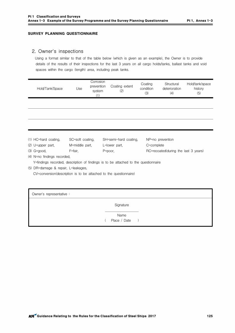
Pt 1 Classification and Surveys
Annex 1-3 Example of the Survey Programme and the Survey Planning Questionnaire Pt 1, Annex 1-3
Guidance Relating to the Rules for the Classification of Steel Ships 2017 125
SURVEY PLANNING QUESTIONNAIRE
2. Ow ner' s inspections
Using a format similar to that of the table below (which is given as an example), the Owner is to provide
details of the results of their inspections for the last 3 years on all cargo holds/tanks, ballast tanks and void
spaces within the cargo (length) area, including peak tanks.
Hold/Tank/Space Use
Corrosion
prevention
system
(1)
Coating extent
(2)
Coating
condition
(3)
Structural
deterioration
(4)
Hold/tank/space
history
(5)
(1) HC=hard coating, SC=soft coating, SH=semi-hard coating, NP=no prevention
(2) U=upper part, M=middle part, L=lower part, C=complete
(3) G=good, F=fair, P=poor, RC=recoated(during the last 3 years)
(4) N=no findings recorded,
Y=findings recorded, description of findings is to be attached to the questionnaire
(5) DR=damage & repair, L=leakages,
CV=conversion(description is to be attached to the questionnaire)
Owner's representative :
Signature
Name
( Place / Date )

Pt 1 Classification and Surveys
Annex 1-3 Example of the Survey Programme and the Survey Planning Questionnaire Pt 1, Annex 1-3
126 Guidance Relating to the Rules for the Classification of Steel Ships 2017
SURVEY PLANNING QUESTIONNAIRE
3. Reports of Port State Control inspections
List the reports of Port State Control inspections containing hull structural related deficiencies and relevant
information on rectification of the deficiencies:
4. Safety Management System
List non-conformities related to hull maintenance, including the associated corrective actions:
5. Name and address of the approv ed thick ness measurement company
Name Address Approved by

Pt 1 Classification and Surveys
Annex 1-4 Owners Inspection Report Pt 1, Annex 1-4
Guidance Relating to the Rules for the Classification of Steel Ships 2017 127
Annex 1-4 Owners Inspection Report
The Owner of ships subject to the enhanced survey programme such as bulk carriers, oil tankers and chemical tank-ers, etc. is to complete the Owner Inspection Report and retain it inside the ship, according to requirement Ch 3, 103. of the Rules. An example of the Owner Inspection Report is shown in Table 1.
Table 1 Example of Owner Inspection Report
Owners Inspection Report(Structural Condition)
◦ Ship's Name : ◦ Tank No./Hold No. :
◦ Grade of Steel :
․ Deck : ․ Side :
․ Bottom : ․ Longi. BHD :
․ Trans. BHD :
Elements Cracks Buckling Corrosion Coating Cond. Pitting Rep., Mod Other
Deck
Bottom
Side
Longi. BHD
Trans BHD
◦ Repairs carried out due to :
◦ Thickness measurements carried out :
․ Date :․ Result in General :
◦ Overdue Survey :
◦ Outstanding Conditions of Class :
◦ Comments :
◦ Date of Inspection :
◦ Inspected by :
◦ Signature :

Pt 1 Classification and Surveys
Annex 1-5 Thickness Measurement Method for Hull Structural Member Pt 1, Annex 1-5
128 Guidance Relating to the Rules for the Classification of Steel Ships 2017
Annex 1-5 Thickness Measurement Method for Hull Structural Members
1. General
(1) Purpose of thickness measurement(A) Corrosion seems to be one of the common denominators in many cases of serious hull cas-
ualties resulting in losses of vessels, cargoes and human lives. The purpose of thickness measurement described in the Rules is to prevent vessels from hull casualties. Information provided in the report of hull thickness measurements for a vessel put in service indicates that the vessel is maintaining sufficient local and global strength, if necessary renewal/repair works can be made accordingly. Therefore, thickness measurement reports giving information for the assessment of hull strength(including watertight integrity) as well as for the main-tenance of the hull is to be carefully considered.
(B) Where the ship has been constructed with FRP, aluminum alloy or other anti-corrosion ma-terials, the thickness measurements may be dispensed with.
(2) Extent of thickness measurementThe standard extent of thickness measurements complying with the "Rules for Classification of Steel Ships" is given in Table 4 to Table 13. However, the extent of thickness measurements may be specially considered by the Society, considering the coating and corrosion condition.
(3) Thickness measurement report (A) The thickness measurement report submitted to the Society shall include the general partic-
ulars as shown in Table 19, measuring position, diagram with details of the position to be measured, original thickness, maximum allowable diminution and present thickness(gauged) and diminution, etc. Reporting form shown in Table 20(or equivalent form) is to be used for recording measuring position, original thickness, maximum allowable diminution, present thickness(gauged) and diminution, etc.
(B) The thickness measurement report is to be verified and countersigned by the attending Surveyor, and the record is to be kept in the Society and on board the ship.
2. Wear Limit
(1) General(A) This annex provides standard of wear limit for decision of repair of main hull structural
members. Wear limit or allowable wear quantity means allowable wear limit.(B) When worn down thickness of hull structural members exceed the wear limit, inspections
are to be carried out in detail and corresponding hull structural members are to be renewed by the date recommended by the Surveyor.
(C) Wear limit provided by this annex is based on the requirements and scantlings during construction. Therefore, the wear limit for the structural members which have scantlings larger than the required ones and margin in strength may be considered appropriately.
(D) Wear limit on hull structural members not provided by this annex follows what is deemed appropriate by the Surveyor.
(2) Wear limit on hull structural members(A) Wear limits on structural members are provided in Table 1. However, for vessels built un-
der IACS Common Structural Rules(Pt 11, Pt 12 or Pt 13), Ch 3, 105. 2 of the Rules is to be applied.
(B) Value of wear limit indicates the limit on equally distributed wearing.(C) When partial corrosion occurs in stress concentrated part, partial replacement or reinforce-
ment shall be carried out without reference to Table 1.

Pt 1 Classification and Surveys
Annex 1-5 Thickness Measurement Method for Hull Structural Member Pt 1, Annex 1-5
Guidance Relating to the Rules for the Classification of Steel Ships 2017 129
Table 1 Wear limit on members
Local
WearLimit
Name of memberWear limit
Class Ⅰ1) Class Ⅱ1) Class Ⅲ1)
Strength deck plating, sheer strake and longitudinals to these members,shell plating, bottom shell plating,bulkhead plating of deep tank4),topside sloping plating,hopper side sloping plating,inner bottom plating
20 % oforiginal thickness
(20 % oforiginal
thickness)+ 1 mm
1 mm
Floor & girder of double bottom,web and face of primary supporting member
20 % oforiginal thickness
25 % oforiginal thickness
Effective deck5) plating,superstructure deck plating,deck plating inside the line of cargo hatch openings,watertight bulkhead plating other than bulkhead plating of deep tank,hatch cover(including stiffeners),hatch coaming(including stiffeners),web, face and brackets of secondary stiffener3)
25 % oforiginal thickness
30 % oforiginal thickness
Web, face and brackets of frames in cargo hold/tank
20 % oforiginal thickness
or 1.5 mm,whichever greater
25 % oforiginal thickness
or 2.5 mm,whichever
greater
Partial corrosion (e.g pitting)30 % of
original thickness35 % of
original thickness
(NOTES)1) For ships classed through the Classification Survey during Construction : the Class I, II and III
are as follow.(a) Class I : It is applied to ships having one or two of the following characteristics. (i) Ships, with of length of 90 m and above, which are classed with Classification Survey
during Construction in accordance with the Rules after 1st July 1998. (ii) Ships carry for liquid cargo, which are classed with Classification Survey during
Construction in accordance with the Rules after 1st July 1998.(b) Class II : Ships, other than in Class I and III.(c) Class III : Ships constructed with steel, which is applied to the Rules for the Classification of High Speed and Light Crafts and the Guidance
Relating to the Rules for the Classification of High Speed and Light Crafts.
2) For ships classed through the Classification Survey after Construction, the separate requirements specified by the Society are to be applied.
3) Secondary stiffener refers to the member which is supported by the primary supporting member and does not support another reinforcement member.
4) Definition of deep tank is specified in Pt 3, Ch 15, 101. of the Rules.5) Definition of effective deck is specified in Pt 3, Ch 5, 103. of the Rules.
Wearrelating to theShearing Strength
The shearing strength evaluation is to be carried out in any of the following cases when the thickness measurement for the longitudinal strength evaluation is carried out in accordance with the separate re-quirements specified by the Society.
1) For oil tankers(including chemical tankers), the average corrosion of any stake in side shell or lon-gitudinal bulkhead exceeds the followings,
Class I : 2.0 mmClass II : 3.0 mm
2) For liquefied gas carriers, the average corrosion of any stake in side shell bulkhead exceeds the followings, or
Class I : 1.5 mmClass II : 2.5 mm
3) For bulk carriers(including ore carriers) intended for alternate loading, the average corrosion of any stake in side shell or longitudinal bulkhead exceeds the followings
Class I : 1.5 mmClass II : 2.5 mm

Pt 1 Classification and Surveys
Annex 1-5 Thickness Measurement Method for Hull Structural Member Pt 1, Annex 1-5
130 Guidance Relating to the Rules for the Classification of Steel Ships 2017
(3) Wear limit of hold hatch cover of bulk carriers which are contracted for construction after 1st July 1998 and before 1st January 2004 and designed by the Rules Pt 7, Ch 3, Sec 9 is to be determined in accordance with the following requirements.(A) Single skin hatch covers and the pontoon hatch covers
(a) Steel renewal is required where the gauged thickness is worn more than 1.5 mm (less than mm ). The net thickness is the thickness obtained by subtracting the corrosion addition from the required thickness.
(b) Where the gauged thickness is worn within the range 1.0 mm and 1.5 mm ( mm and mm ), coating applied in accordance with coating manufacturer's require-ments or annual gauging may be adopted as an alterative to steel renewal.
(B) Internal structural members of pontoon hatch coversThickness gauging is required when plating renewal is to be carried out in accordance with previous (a) or when it is deemed necessary, at the discretion of the Society, on the basis of the plating corrosion or deformation condition. In these cases, steel renewal for the in-ternal structures is required where the gauged thickness is worn more than 1.5 mm (less than ).
(4) Wear limit of hold hatch cover and hatch coatings of all bulk carriers, ore carriers and combi-nation carriers which are contracted for construction on or after 1st January 2004 and designed by the Rules Pt 7, Ch 3, Sec 9 is to be determined in accordance with the following requirements.(A) Single skin hatch covers and double skin hatch covers
(a) Steel renewal is required where the gauged thickness is worn more than 1.5 mm (less than mm ).
(b) Where the gauged thickness is worn within the range 1.0 mm and 1.5 mm ( mm and mm ), coating applied in accordance with coating manufacturer's require-ments or annual gauging may be adopted as an alterative to steel renewal. Coating is to be maintained in GOOD condition, as defined in Ch 2, 101. 16 of the Rules
(B) Internal structural members of double skin hatch coversThickness gauging is required when plating renewal is to be carried out in accordance with previous (a) or when it is deemed necessary, at the discretion of the Society, on the basis of the plating corrosion or deformation condition. In these cases, steel renewal for the in-ternal structures is required where the gauged thickness is worn more than 1.5 mm (less than ).
(C) Hatch coamings(a) Steel renewal is required where the gauged thickness is worn more than 1.0 mm (less
than mm ).(b) Where the gauged thickness is worn within the range 0.5 mm and 1.0 mm ( mm
and mm ), coating applied in accordance with coating manufacturer's require-ments or annual gauging may be adopted as an alterative to steel renewal. Coating is to be maintained in GOOD condition, as defined in Ch 2, 101. 16 of the Rules
(5) The renewal thickness() of steel hatch covers and coamings in position I and II on ex-posed decks, subjected to Pt 4, Ch 2, of ships other than bulk carriers which are keel laid on or after 1st January 2005 are to be in accordance with as followings. (Refer to Pt 4, Ch 2, 105. 2)
(mm)
Where,
: as built thickness
: corrosion addition according to Pt 4, Ch 2, 105. Table 4.2.1 of the Rules
Where the corrosion addition is 1.0 mm, the renewal thickness may be given by the
following formula
(mm)
(6) Wear limit of corrugated transverse watertight bulkheads for bulk carriers, which are contracted for construction after 1st July 1998 and designed by the Rules Pt 7, Ch 3, 1201. is to be de-

Pt 1 Classification and Surveys
Annex 1-5 Thickness Measurement Method for Hull Structural Member Pt 1, Annex 1-5
Guidance Relating to the Rules for the Classification of Steel Ships 2017 131
termined in accordance with the following requirements.(A) Steel renewal is required where the gauged thickness is worn more than 3.0 mm (less than mm ).
(B) Where the gauged thickness is worn within the range 2.5 mm and 3.0 mm ( mm and mm ), coating applied in accordance with coating manufacturer's requirements or annual gauging may be adopted as an alterative to steel renewal.
(7) Corrosion addition and steel renewal of vertically corrugated transverse watertight bulkheads be-tween cargo holds No. 1 and 2 for bulk carriers, which are applied to Pt 7, Annex 7-5, 1 (1) (A) of the Guidance, are to be determined in accordance with the requirements specified in Pt 7, Annex 7-5, 1 (6).
(8) The wastage allowances of supporting hull structures associated with towing and mooring, sub-ject to Pt 4, Ch 10 of the Rules, of ships which are keel laid on or after 1st January 2007 are not to exceed the corrosion addition as specified in Pt 4, Ch 10, 201. 6 and 202. 6 of the Rules.
3. Methods of Thickness Measurement
An essential part of most surveys is the determination of the residual thickness of the structure in critical areas. Ultrasonic thickness gauging by pulse echo method is used almost exclusively for this purpose. However, measuring by drilled holes may also be acceptable. As a method of thick-ness measurement, where ultrasonic thickness gauging methods are used, attention is to be paid to the following:(1) Surface condition
Surfaces upon which the probe makes contact are to be sufficiently free from scale, loose paint, corroded surfaces or other foreign matters to the extent that their presence does not result in in-accurate readings when acoustic couplants such as glycerine or glycerine-water solutions are used during inspection. In special cases, readings through paint film by a special instrument may be accepted.
(2) CouplantsIt is essential that good acoustic contact is achieved between the probe and the surface of the plate being measured. Therefore, acoustic couplants(e.g., coupling fluid; 75 % glycerine-water sol-utions or glycerine) between the probe and surface of material are usually used for better achievements. Where the direction of contact surfaces is vertical or overhead, a paste or liquid with suitable viscosity may be used to prevent acoustic couplants from dropping.
(3) CalibrationsAn instrument is to be calibrated with a reference calibration standard each time it is used, and it is to be recalibrated whenever equipment calibration is suspected of being in error.
4. Location of Thickness Measurement
(1) Thickness measurements for suspect areaAt each Special Survey, the thickness gaugings may be required as a result of Close-up Survey in suspect areas(i.e., locations showing substantial corrosion and/or considered by the Surveyor to be prone to rapid wastage). Details are given in Table 2.
(2) Location and number of thickness measuring pointsThe standard location and number of thickness measuring points and patterns are shown in Table 3. These figures show typical arrangements of ships such as bulk carriers and oil tank-ers, etc. and these may be used as guidance for different type of ships other than those illustrated. The location and number of thickness measuring points for other hull structural mem-bers which are not specified in this Annex are to be in accordance with what considered appro-priate by the Surveyor taking into account of the ship's age and hull structure, etc.
(3) Thickness Measurement at Special SurveyThe standard extent of thickness measurements at each Special Survey are given in Table 4 to Table 13.

Pt 1 Classification and Surveys
Annex 1-5 Thickness Measurement Method for Hull Structural Member Pt 1, Annex 1-5
132 Guidance Relating to the Rules for the Classification of Steel Ships 2017
5. Additional Thickness Measurement
The extent of additional thickness measurement at those areas of substantial corrosion of ships sub-ject to the enhanced survey programme such as bulk carriers, oil tankers and chemical tankers, etc. is shown in Table 14 to Table 18.
6. Sampling method of thickness measurements for longitudinal strength evaluation and re-pair methods for oil tankers or double hull oil tankers subject to the enhanced survey programme
(1) Extent of longitudinal strength evaluationLongitudinal strength should be evaluated within 0.4 amidships for the extent of the hull gird-er length that contains tanks therein and within 0.5 amidships for adjacent tanks which may extent beyond 0.4 amidships, where tanks means ballast tanks and cargo tanks.
(2) Sampling method of thickness measurement(A) Pursuant to the requirements of Ch 3, 304. 4 or 504. 4 of the Rules as applicable, trans-
verse sections should be chosen such that thickness measurements can be taken for as many different tanks in corrosive environments as possible, e.g. ballast tanks sharing a com-mon plane boundary with cargo tanks fitted with heating coils, other ballast tanks, cargo tanks permitted to be filled with sea water and other cargo tanks. Ballast tanks sharing a common plane boundary with cargo tanks fitted with heating coils and cargo tanks permit-ted to be filled with sea water should be selected where present.
(B) The minimum number of transverse sections to be sampled should be in accordance with Ch 3, Table 1.3.5 or Table 1.3.11 of the Rules as applicable. The transverse sections should be located where the largest thickness reductions are suspected to occur or are re-vealed from deck and bottom plating measurements prescribed in (C) and should be clear of areas which have been locally renewed or reinforced.
(C) At least two points should be measured on each deck plate and/or bottom shell plate re-quired to be measured within the cargo area in accordance with the requirements of Ch 3, Table 1.3.5 or Table 1.3.11 of the Rules as applicable.
(D) Within 0.1 (where is the ship's moulded depth) of the deck and bottom at each trans-verse section to be measured in accordance with the requirements of Ch 3, Table 1.3.5 or Table 1.3.11 of the Rules as applicable, every longitudinal and girder should be measured on the web and face plate, and every plate should be measured at one point between longitudinals.
(E) For longitudinal members other than those specified in (D) above to be measured at each transverse section in accordance with the requirements of Ch 3, Table 1.3.5 or Table 1.3.11 of the Rules as applicable, every longitudinal and girder should be measured on the web and face plate, and every plate should be measured at least in one point per strake.
(F) The thickness of each compartment should be determined by averaging all of the measure-ments taken in way of the transverse section on each compartment.
(3) Additional measurements where the longitudinal strength is deficient.(A) Where one or more of the transverse sections are found to be deficient in respect of the
longitudinal strength requirements, the number of transverse sections for thickness measure-ment should be increased such that each tank within the 0.5 amidships region has been sampled. Tank spaces that are partially within, but extend beyond, 0.5 region, should be sampled.
(B) Additional thickness measurements should also be performed on one transverse section for-ward and one aft of each repaired area to the extent necessary to ensure that the areas bordering the repaired section also comply with the requirements of the Rules.

Pt 1 Classification and Surveys
Annex 1-5 Thickness Measurement Method for Hull Structural Member Pt 1, Annex 1-5
Guidance Relating to the Rules for the Classification of Steel Ships 2017 133
(4) Effective repair methods(A) The extent of renewal or reinforcement carried out to comply with the Rules should be in
accordance with (B) below.(B) The minimum continuous length of a renewed or reinforced structural member should be
not less than twice the spacing of the primary members in way. In addition, the thickness diminution in way of the butt joint of each joining member forward and aft of the re-placed member(plates, stiffeners, girder webs and flanges, etc.) should not be within the substantial corrosion range(75% of the allowable webs and flanges, etc.) should not be within the substantial corrosion range(75% of the allowable diminution associated with each particular member). Where differences in thickness at the butt joint exceed 15% of the lower thickness, a transition taper should be provided.
(C) Alternative repair methods involving the fitting of straps or structural member modification should be subject to special consideration. In considering the fitting of straps, it should be limited to the following conditions:
(a) to restore and/or increase longitudinal strength;(b) the thickness diminution of the deck or bottom plating to be reinforced should not be
within the substantial corrosion range(75% of the allowable diminution associated with the deck plating):
(c) the alignment and arrangement, including the termination of the straps, is in accordance with the separate requirements specified by the Society;
(d) the straps are continuous over the entire 0.5 amidships length; and(e) continuous fillet welding and full penetration welds are used at butt welding and, de-
pending on the width of the strap, slot welds. The welding procedures applied should be acceptable to the Society.
(D) The existing structure adjacent to replacement areas and in conjunction with the fitted straps, etc. should be capable of withstanding the applied loads, taking into account the buckling resistance and the condition of welds between the longitudinal members and hull envelope plating.

Pt 1 Classification and Surveys
Annex 1-5 Thickness Measurement Method for Hull Structural Member Pt 1, Annex 1-5
134 Guidance Relating to the Rules for the Classification of Steel Ships 2017
Table 2 Suspect areas on which attention is to be paid
Location Measuring Points
Deck and upper structures
Special attention is to be given on fore parts (forward of 0.5 amidships) of strength deck, areas with standing bilges and members with originally light scantlings in addition to the following:
F'cle, poop and deckhouse
Break bulkheads of superstructures, Lower parts of deckhouse walls, Pipe penetration areas, Areas with drain plugs, Deck platings of superstructures, Deck platings in way of bilge-ways, deck scuppers, deck machinery(winches, windlasses etc.), fair-leaders and bollards etc.
Deck platings inside line of hatch openings and inside superstructures and deckhouses
Deck platings inside line of openings between cargo hatch-ways, and of deck platings inside superstructures and deckhouses.
Hatch coamings and coaming staysLower parts attached to upper deck, Parts around steam pipes.
Bulwark platings and bulwark staysLower parts attached to upper deck, End parts connected to superstructures and deckhouses,Platings around freeing ports.
Winch foundation Special attention is to be given to steam winch foundations
Steel hatch covers Steel pontoon covers (including cleats, etc.)
Shells
Wind and water strakesSpecial attention is to be given to fore and after part outside of 0.5 amidships.
Shell platings connected to end bracketsAfter removal of limber boards and cement chocks, Close-up Survey is required.
Shells attached to hold frames Special attention is to be given to groovings on shells.
Shells around chain lockers -
Hard spotted shellsSpecial attention is to be given to shells (parts or positions) in ballast tanks
Internal members
Special attention is to be given to areas with high humidity, standing bilges and poorly ventilated spaces in addition to the following :
Joint parts between hold frames and frame brackets
After removal of limber board, those parts are to be exam-ined (problem areas in aged ships)
Intersections between transverse W/T Bulkhead and inner bottom
After removal of bottom ceilings, those parts are to be examined.
Tank top platings of double bottom tanks and of deep tanks used as ballast tanks
-
Fillet weld parts between hold frames and side shells
Special attention is to be paid to hold frames in intermittent welds.
Bilge wellsSpecial attention si to be given to bilge wells in E/R and bilge wells with piping arrangements.
Inner bottom platings under pillars -
Internal members around sea water pumps in E/R
-
Sea chest boundaries in E/R -
Joint parts between shaft tunnel and inner bottom
Close-up Survey is required for aged ships
Intersections between tweendeck frames or tweendeck bulkheads and lower deck
-
Lower parts of collision BHD and bottom of chain lockers
-
Intersections between panting/side stringers and frames, and end parts, slot areas in way of panting/side stringers
-

Pt 1 Classification and Surveys
Annex 1-5 Thickness Measurement Method for Hull Structural Member Pt 1, Annex 1-5
Guidance Relating to the Rules for the Classification of Steel Ships 2017 135
Table 2 Suspect areas on which attention is to be paid (continued)
Location Measuring Points
Insideof tanks
Special attention is to be paid to the combined tanks (ballast and fuel oil), prone to rapid wastage, in addition to the following:
All of ballast tanks in front of E/R boundaries
Close-up Survey is required for tank top, bottom and boundary plat-ings of the tanks not forming their boundaries by full envelope (both shells and decks). And special attention is to be paid to connections between frames and brackets, and on docking brackets, lightening holes
Double bottom ballast tanks, side ballast tanks, and shaft tunnels
Special attention is to be paid to inner bottom platings meeting bulk-heads, edge platings reaching to tank side brackets, and on lightening holes/slots in way of girders and on bottom shells around striking pads below sounding pipes.
Bulkheads facing a heated zone
Special attention is to be paid to bulkheads facing E/R space, or fuel oil tanks being heated.
Bottom platings below sound-ing pipes
Special attention is to be paid to bilge tanks in E/R
Chain lockers in fore peak tanks
Special attention is to be paid to bottom platings and side boundaries of chain lockers.

Pt 1 Classification and Surveys
Annex 1-5 Thickness Measurement Method for Hull Structural Member Pt 1, Annex 1-5
136 Guidance Relating to the Rules for the Classification of Steel Ships 2017
Table 3-1 Location and number of thickness measuring points - Non-CSR Ships
Table 3-1 is to be applied to vessels not built under IACS Common Structural Rules(Pt 11, Pt 12 or Pt 13)(i.e. Non-CSR Ships)
Items Location and number of thickness measuring points
Transverse Section
1. For oil tankers, chemical tankers or double hull oil tankers subject to the enhanced survey programme (See Fig 1 and Fig 2)(1) At each transverse section, every plate within 0.1D(where D is the ship's mould-
ed depth) of the deck and bottom is to be measured at one point between lon-gitudinals, and all the other plate is to be measured at least one point per strake.
(2) Where the thickness measurements for a transverse section are to include all longitudinal members, every longitudinal is to be measured at one point on the web and face plate.
2. For single skin bulk carriers, double skin bulk carriers or general dry cargo ships (See Fig 3 and Fig 4)
(1) At each transverse section, every plate of the deck and inner bottom is to be measured at one point between longitudinals, and all the other plate is to be measured at least one point per strake.
(2) Where the thickness measurements for a transverse section are to include all longitudinal members, every longitudinal is to be measured at one point on the web and face plate.
3. For general ships other than 1 and 2 above (See Fig 5)(1) At each transverse section, every plate is to be measured at least two points per
strake.(2) Where the thickness measurements for a transverse section are to include all
longitudinal members, every longitudinal is to be measured at one point on the web and face plate.
4. For transversely framed vessels, a transverse section includes adjacent frames and their end connections in way of transverse sections.
(For oil tankers, chemical tankers or double hull oil tankers subject to the en-hanced survey programme see Fig 1 and Fig 2, for single skin or double skin bulk carriers see Fig 6 and Fig 8, for other ships see Fig 7)
Transverse Section of deck, side shell and
bottom plating
At least two points on each plate(either at each 1/4 extremity of plate or at repre-sentative areas of average corrosion) are to be measured in the transverse section concerned.
Selected plates: Selected plates on deck(including deck inside line of hatch openings), tank top, bottom, inner bottom plates, etc. and wind-and-water strakes
At least two points are to be measured at representative areas of average corrosion. Where the length of the plate exceeds 6 m, two points per 6 m are to be gauged additionally. Where plates cross ballast/cargo tank boundaries separate measurements for the area of plating in way of each type of tank are to be taken. In case of side shell plating, one or two wind and water strakes are to be gauged according to No. of Special Survey. The gauging location of each plate may be selected by the attending Surveyor in consideration of the corrosion pattern.
All plates: All deck(including deck inside line of hatch openings), tank top, bottom, inner bottom plates, etc. and wind-and-water strakes
At least two points on each plate(either at each 1/4 extremity of plate or at repre-sentative areas of average corrosion) are to be measured. Where the length of the plate exceeds 6 m, two points per 6 m are to be gauged additionally. Where plates cross ballast/cargo tank boundaries separate measurements for the area of plating in way of each type of tank are to be taken.
Selected internal structures: Selected internal structure such as floors and longitudinals, transverse frames, web frames, deck beams, girders
The internal structural members to be measured in each space internally surveyed are to be 1. at least 10% outside the cargo (length) area, 2. at least 20% within the cargo (length) area.(For oil tankers, chemical tankers or double hull oil tankers subject to the enhanced survey programme see Fig 1 and Fig 2, for single skin or double skin bulk carriers see Fig 6, for other ships see Fig 7)

Pt 1 Classification and Surveys
Annex 1-5 Thickness Measurement Method for Hull Structural Member Pt 1, Annex 1-5
Guidance Relating to the Rules for the Classification of Steel Ships 2017 137
Table 3-1 Location and number of thickness measuring points - Non-CSR Ships (continued)
Items Location and number of thickness measuring points
Selected side shell frames in cargo holds for single skin bulk
carriers or general dry cargo ships
1. Include side shell frame, upper and lower end attachments and adjacent shell plating.2. 25% of frames: one out of four frames should preferably be chosen throughout the
cargo hold length on each side.3. 50% of frames: one out of two frames should preferably be chosen throughout the
cargo hold length on each side.4. "Selected frames" means at least 3 frames on each side of cargo holds.(For single skin bulk carriers see Fig 6, for general dry cargo ships see Fig 7)
Transverse webs in ballast tanks for single
skin bulk carriers, double skin bulk
carriers or general dry cargo ships
One of the representative tanks of each type (i.e. topside or hopper or side tank) is to be chosen in the forward part.(For single skin or double skin bulk carriers see Fig 6, for general dry cargo ships see Fig 7)
Transverse frames in double skin tanks for
double skin bulk carriers
25% of transverse frames: one out of four transverse frames is to be chosen preferably throughout the double skin tank length. (See Fig 8)
Transverse bulkheads
1. For oil tankers, chemical tankers or double hull oil tankers subject to the enhanced survey programme: See Fig 1 and Fig 2
2. For single skin bulk carriers, double skin bulk carriers or general dry cargo ships (See Fig 9 to Fig 11)
(1) Transverse bulkheads in cargo holds- Includes bulkheads plating, stiffeners and girders, including internal structure of upper and lower stools, where fitted.- Two selected bulkheads : one is to be the bulkhead between the
two foremost cargo holds and the second may be chosen in other positions
(2) One transverse bulkhead in each cargo hold- The Close-up Survey and related thickness measurements are to be carried out on one side of the bulkhead; the side is to be chosen based on the outcome of the Overall Survey of both sides. In the event of doubt, the Surveyor may also require (possibly partial) Close-up Survey and related thick-ness measurements on the other side.
(3) Transverse bulkheads in one ballast tank- The ballast tank is to be chosen based on the history of ballasting among those prone to have the most severe conditions.
Cargo hold hatch covers and coamings
See Fig 12
All under deck structure inside line of hatch openings between
cargo hold hatches
At each short longitudinal girder: three points for web plating(fwd/middle/aft), single point for face plate, one point for web plating and one point for face plating of trans-verse beam in way. At each ends of transverse beams, one point for web plating and one point for face plating.(See Fig 13)
(NOTES) 1. mark : means the location to be measured. 2. ×, ˅ mark : means the point to be measured.

Pt 1 Classification and Surveys
Annex 1-5 Thickness Measurement Method for Hull Structural Member Pt 1, Annex 1-5
138 Guidance Relating to the Rules for the Classification of Steel Ships 2017
Table 3-1 Location and number of thickness measuring points - Non-CSR Ships (continued)
Fig 1 Locations of measurements of oil tankers and chemical tankers

Pt 1 Classification and Surveys
Annex 1-5 Thickness Measurement Method for Hull Structural Member Pt 1, Annex 1-5
Guidance Relating to the Rules for the Classification of Steel Ships 2017 139
Table 3-1 Location and number of thickness measuring points - Non-CSR Ships (continued)
Fig 2 Locations of measurements of double hull oil tankers
Fig 3 Locations of measurements on transverse section of single skin or double skin bulk carriers

Pt 1 Classification and Surveys
Annex 1-5 Thickness Measurement Method for Hull Structural Member Pt 1, Annex 1-5
140 Guidance Relating to the Rules for the Classification of Steel Ships 2017
Table 3-1 Location and number of thickness measuring points - Non-CSR Ships (continued)
Fig 4 Locations of measurements on transverse section of general dry cargo ships
(Notes) It may also apply to other type of transverse section.
Fig 5 Locations of measurements on transverse section of general ships

Pt 1 Classification and Surveys
Annex 1-5 Thickness Measurement Method for Hull Structural Member Pt 1, Annex 1-5
Guidance Relating to the Rules for the Classification of Steel Ships 2017 141
Table 3-1 Location and number of thickness measuring points - Non-CSR Ships (continued)
(Bulk Carriers)
(Ore Carriers)
(Notes) The gauging pattern for web plating is to be a three point pattern for zones A, C and D, and a two point pattern for zone B (see figure). The gauging report is to reflect the average reading. The average reading is to be compared with the allowable thickness. If the web plating has general corrosion the this pattern is to be expanded to a five point pattern.
Fig 6 Locations of measurements on structural members in cargo holds and
ballast tanks of single skin or double skin bulk carriers

Pt 1 Classification and Surveys
Annex 1-5 Thickness Measurement Method for Hull Structural Member Pt 1, Annex 1-5
142 Guidance Relating to the Rules for the Classification of Steel Ships 2017
Table 3-1 Location and number of thickness measuring points - Non-CSR Ships (continued)
(Notes) It may also apply to other ship types.
Fig 7 Locations of measurements on selected internal structural members
Fig 8 Locations of measurements on transverse frame in double skin tank of double skin bulk carriers

Pt 1 Classification and Surveys
Annex 1-5 Thickness Measurement Method for Hull Structural Member Pt 1, Annex 1-5
Guidance Relating to the Rules for the Classification of Steel Ships 2017 143
Table 3-1 Location and number of thickness measuring points - Non-CSR Ships (continued)
Single skin bulk carriers
Double skin bulk carriers
(Notes) Measurements to be taken in each shaded area as per views A-A and B-B. Additional measurements to internal structure of upper and lower stools to be added, e.g. two points in
the upper and two points in the lower stools to be indicated in section A-A.
Fig 9 Locations of measurements on cargo hold transverse bulkheads of single skin
or double skin bulk carriers

Pt 1 Classification and Surveys
Annex 1-5 Thickness Measurement Method for Hull Structural Member Pt 1, Annex 1-5
144 Guidance Relating to the Rules for the Classification of Steel Ships 2017
Table 3-1 Location and number of thickness measuring points - Non-CSR Ships (continued)
(Notes)
1. Cargo hold bulkhead/watertight floor plating to be measured as per main view.
2. One stiffener out of three to be measured as per view A-A.
3. It may also apply to other ship types.
Fig 10 Locations of measurements on transverse bulkheads of general dry cargo ships

Pt 1 Classification and Surveys
Annex 1-5 Thickness Measurement Method for Hull Structural Member Pt 1, Annex 1-5
Guidance Relating to the Rules for the Classification of Steel Ships 2017 145
Table 3-1 Location and number of thickness measuring points - Non-CSR Ships (continued)
(Notes) Measurements to be taken in each vertical section as per view A-A.
Fig 11 Locations of measurements on transverse bulkheads in topside, hopper, double hull and double
bottom ballast tanks of single skin or double skin bulk carriers

Pt 1 Classification and Surveys
Annex 1-5 Thickness Measurement Method for Hull Structural Member Pt 1, Annex 1-5
146 Guidance Relating to the Rules for the Classification of Steel Ships 2017
Table 3-1 Location and number of thickness measuring points - Non-CSR Ships (continued)
(Notes) ➀ For each hatch covers, three sections at L/4, L/2 and 3L/4 of hatch cover length, including: - one measurement of each hatch cover plate and skirt plate - measurements of adjacent beams or girder(including stiffeners) - one measurement of coaming plates and coaming flange, each side ➁ For each hatch covers, one measurement of hatch cover skirt plate, coaming plate and coaming flange on
both ends ➂ One measurement of one out of three hatch coaming brackets and bars, on both sides and both ends ➃ One measurement of each hatch coaming end bracket
Fig 12 Locations of measurements on hatch covers and coamings

Pt 1 Classification and Surveys
Annex 1-5 Thickness Measurement Method for Hull Structural Member Pt 1, Annex 1-5
Guidance Relating to the Rules for the Classification of Steel Ships 2017 147
Table 3-1 Location and number of thickness measuring points - Non-CSR Ships (continued)
Fig 13 Locations of measurements on underdeck structure

Pt 1 Classification and Surveys
Annex 1-5 Thickness Measurement Method for Hull Structural Member Pt 1, Annex 1-5
148 Guidance Relating to the Rules for the Classification of Steel Ships 2017
Table 3-2 Location and number of thickness measuring points - CSR Ships
Table 3-2 is to be applied to vessels built under IACS Common Structural Rules(Pt 11, Pt 12 or Pt 13)(i.e. CSR Ships).
1) CSR bulk carriers
Items location and number of thickness measuring points Figure reference
Selected plates on deck, tank top, bottom, double bottom and wind-and-water area
"Selected" means at least a single point on one out of three plates, to be chosen on representative areas of average corro-sion
All deck, tank top and bot-tom plates and wind-and-water strakes
At least two points on each plate to be taken either at each 1/4 extremity of plate or at representative areas of average corrosion
Transverse section - For single skin bulk carriers :A transverse section includes all longitudinal members such as plating, longitudinals and girders at the deck, side, bottom, inner bottom and hopper side plating, longitudinal bulkhead and bottom plating in top wing tanks.
- For double skin bulk carriers :A transverse section includes all longitudinal members such as plating, longitudinals and girders at the deck, side, bottom, inner bottom and hopper sides, inner sides and top wing inner sides.
Fig 1
All cargo hold hatch cov-ers and coamings
Including plates and stiffeners Locations of points are given in Fig 2
Transverse section of deck plating outside line of car-go hatch openings
Two single points on each deck plate (to be taken either at each 1/4 extremity of plate or at representative areas of aver-age corrosion) between the ship sides and hatch coamings in the transverse section concerned
All deck plating and under deck structure inside line of hatch openings between cargo hold hatches
"All deck plating" means at least two points on each plate to be taken either at each 1/4 extremity of plate or at repre-sentative areas of average corrosion.
"Underdeck structure": at each short longitudinal girder: three points for web plating(fwd/middle/aft), single point for face plate, one point for web plating and one point for face plat-ing of transverse beam in way. At each ends of transverse beams, one point for web plating and one point for face plating.
Extent of areas is shown in Annex 1-6, 1 (2) or (6) of the Guidance
Location of points are given in Fig 6

Pt 1 Classification and Surveys
Annex 1-5 Thickness Measurement Method for Hull Structural Member Pt 1, Annex 1-5
Guidance Relating to the Rules for the Classification of Steel Ships 2017 149
Table 3-2 Location and number of thickness measuring points - CSR Ships (continued)
Items location and number of thickness measuring points Figure reference
Single skin bulk carriers: Selected side shell frames in cargo holds
Includes side shell frame, upper and lower end attachments and adjacent shell plating.
25% of frames: one out of four frames should preferably be chosen throughout the cargo hold length on each side.
50% of frames: one out of two frames should preferably be chosen throughout the cargo hold length on each side.
"Selected frames" means at least 3 frames on each side of cargo holds
Extent of areas is shown in Annex 1-6, 1 (2) or (6) of the Guidance
Locations of points are given in Fig 3
Double skin bulk carriers: Transverse frame in dou-ble skin tank
Fig 1
Transverse bulkheads in cargo holds
Includes bulkhead plating, stiffeners and girders, including in-ternal structure of upper and lower stools, where fitted.
Two selected bulkheads: one is to be the bulkhead between the two foremost cargo holds and the second may be chosen in other positions
Areas of measure-ments are shown in Annex 1-6, 1 (2) or (6) of the Guidance
Locations of points are given in Fig 4
One transverse bulkhead in each cargo hold
This means that the Close-up Survey and related thickness measurements are to be performed on one side of the bulk-head; the side is to be chosen based on the outcome of the overall survey of both sides. In the event of doubt, the Surveyor may also require (possibly partial) Close-up Survey and related thickness measurements on the other side
Areas of measure-ments are shown in Annex 1-6, 1 (2) or (6) of the Guidance
Locations of points are given in Fig 4
Transverse bulkheads in one topside, hopper and double bottom ballast tank
Includes bulkhead and stiffening systems.
The ballast tank is to be chosen based on the history of bal-lasting among those prone to have the most severe conditions
Locations of points are given in Fig 5
Transverse webs in ballast tanks
Includes web plating, face plates, stiffeners and associated plating and longitudinals.
One of the representative tanks of each type (i.e. topside or hopper or side tank) is to be chosen in the forward part
Areas of measure-ments are shown in Annex 1-6, 1 (2) or (6) of the Guidance
Locations of points are given in Fig 3
(NOTES)1. mark : means the location to be measured.2. ×, ˅ mark : means the point to be measured.

Pt 1 Classification and Surveys
Annex 1-5 Thickness Measurement Method for Hull Structural Member Pt 1, Annex 1-5
150 Guidance Relating to the Rules for the Classification of Steel Ships 2017
Table 3-2 Location and number of thickness measuring points - CSR Ships (continued)
Single skin bulk carriers
Double skin bulk carriers
(Notes) Measurements are to be taken on both port and starboard sides of the selected transverse section.
Fig 1 Locations of measurements on transverse section of single skin or double skin bulk carriers

Pt 1 Classification and Surveys
Annex 1-5 Thickness Measurement Method for Hull Structural Member Pt 1, Annex 1-5
Guidance Relating to the Rules for the Classification of Steel Ships 2017 151
Table 3-2 Location and number of thickness measuring points - CSR Ships (continued)
(Notes)1. Three sections at L/4, L/2, 3L/4 of hatch cover length, including:
• one measurement of each hatch cover plate and skirt plate• measurements of adjacent beams and stiffeners• one measurement of coaming plates and coaming flange, each side
2. Measurements of both ends of hatch cover skirt plate, coaming plate and coaming flange3. One measurement(two points for web plate and one point for face plate) of one out of three hatch coam-
ing brackets and bars, on both sides and both ends
Fig 2 Locations of measurements on hatch covers and coamings

Pt 1 Classification and Surveys
Annex 1-5 Thickness Measurement Method for Hull Structural Member Pt 1, Annex 1-5
152 Guidance Relating to the Rules for the Classification of Steel Ships 2017
Table 3-2 Location and number of thickness measuring points - CSR Ships (continued)
(Notes) The gauging pattern for web plating is to be a three point pattern for zones A, C and D, and a two point pattern for zone B (see figure). The gauging report is to reflect the average reading. The average reading is to be compared with the allowable thickness. If the web plating has general corrosion then this pattern is to be expanded to a five point pattern.
Single skin bulk carriers
Double skin bulk carriers
Fig 3 Locations of measurements on structural members in cargo holds and ballast tanks of single skin
bulk carriers and in ballast tanks(topside or hopper or side tank) of double skin bulk carriers

Pt 1 Classification and Surveys
Annex 1-5 Thickness Measurement Method for Hull Structural Member Pt 1, Annex 1-5
Guidance Relating to the Rules for the Classification of Steel Ships 2017 153
Table 3-2 Location and number of thickness measuring points - CSR Ships (continued)
Single skin bulk carriers
Double skin bulk carriers
(Notes) Measurements to be taken in each shaded area as per views A-A and B-B. Additional measurements to internal structure of upper and lower stools to be added, e.g. two points
in the upper and two points in the lower stools to be indicated in section A-A.
Fig 4 Location of measurements on cargo hold transverse bulkheads of single skin or
double skin bulk carriers

Pt 1 Classification and Surveys
Annex 1-5 Thickness Measurement Method for Hull Structural Member Pt 1, Annex 1-5
154 Guidance Relating to the Rules for the Classification of Steel Ships 2017
Table 3-2 Location and number of thickness measuring points - CSR Ships (continued)
(Notes) Measurements to be taken in each vertical section as per view A-A Two additional measurements to internal structure of double bottom tank to be added at midspan.
Fig 5 Locations of measurements on transverse bulkheads of topside, hopper, double hull and
double bottom ballast tanks of single skin or double skin bulk carriers

Pt 1 Classification and Surveys
Annex 1-5 Thickness Measurement Method for Hull Structural Member Pt 1, Annex 1-5
Guidance Relating to the Rules for the Classification of Steel Ships 2017 155
Table 3-2 Location and number of thickness measuring points - CSR Ships (continued)
Fig 6 Locations of measurements on underdeck structure
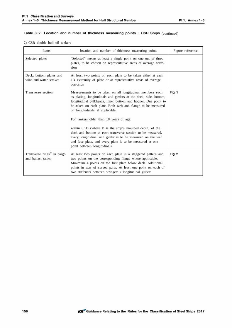
Pt 1 Classification and Surveys
Annex 1-5 Thickness Measurement Method for Hull Structural Member Pt 1, Annex 1-5
156 Guidance Relating to the Rules for the Classification of Steel Ships 2017
Table 3-2 Location and number of thickness measuring points - CSR Ships (continued)
2) CSR double hull oil tankers
Items location and number of thickness measuring points Figure reference
Selected plates "Selected" means at least a single point on one out of three plates, to be chosen on representative areas of average corro-sion
Deck, bottom plates and wind-and-water strakes
At least two points on each plate to be taken either at each 1/4 extremity of plate or at representative areas of average corrosion
Transverse section Measurements to be taken on all longitudinal members such as plating, longitudinals and girders at the deck, side, bottom, longitudinal bulkheads, inner bottom and hopper. One point to be taken on each plate. Both web and flange to be measured on longitudinals, if applicable.
For tankers older than 10 years of age:
within 0.1D (where D is the ship’s moulded depth) of the deck and bottom at each transverse section to be measured, every longitudinal and girder is to be measured on the web and face plate, and every plate is to be measured at one point between longitudinals.
Fig 1
Transverse rings3) in cargo and ballast tanks
At least two points on each plate in a staggered pattern and two points on the corresponding flange where applicable.Minimum 4 points on the first plate below deck. Additional points in way of curved parts. At least one point on each of two stiffeners between stringers / longitudinal girders.
Fig 2

Pt 1 Classification and Surveys
Annex 1-5 Thickness Measurement Method for Hull Structural Member Pt 1, Annex 1-5
Guidance Relating to the Rules for the Classification of Steel Ships 2017 157
Table 3-2 Location and number of thickness measuring points - CSR Ships (continued)
Items location and number of thickness measuring points Figure reference
Transverse bulkheads in cargo tanks
At least two points on each plate. Minimum 4 points on the first plate below main deck.
At least one point on every third stiffener to be taken be-tween each stringer.
At least two points on each plate of stringers and girders, and two points on the corresponding flange. Additional points in way of curved part.
Two points of each diaphragm plate of stools if fitted.
Fig 3
Transverse bulkheads in ballast tanks
At least 4 points on plates between stringers / longitudinal girders, or per plate if stringers / girders not fitted.
At least two points on each plate of stringers and girders, and two points on the corresponding flange. Additional points in way of curved part.
At least one point on two stiffeners between each stringer / longitudinal girder.
Fig 4
Adjacent structural mem-bers
On adjacent structural members one point per plate and one point on every third stiffener / longitudinal.
(NOTES)1. mark : means the location to be measured.2. ×, ˅ mark : means the point to be measured.3. Transverse rings means all transverse material appearing in a cross-section of the ship's hull, in way of a dou-
ble bottom floor, vertical web and deck transverse (definition from IACS Common Structural Rules for Double Hull Oil Tankers(Pt 12 or Pt 13 of the Rules).

Pt 1 Classification and Surveys
Annex 1-5 Thickness Measurement Method for Hull Structural Member Pt 1, Annex 1-5
158 Guidance Relating to the Rules for the Classification of Steel Ships 2017
Table 3-2 Location and number of thickness measuring points - CSR Ships (continued)
Fig 1 Locations of measurements on transverse section of double hull oil tankers
Fig 2 Locations of measurements on transverse rings in cargo and
ballast tanks of double hull oil tankers

Pt 1 Classification and Surveys
Annex 1-5 Thickness Measurement Method for Hull Structural Member Pt 1, Annex 1-5
Guidance Relating to the Rules for the Classification of Steel Ships 2017 159
Table 3-2 Location and number of thickness measuring points - CSR Ships (continued)
Fig 3 Locations of measurements on transverse bulkheads in cargo tanks of double hull oil tankers
Fig 4 Locations of measurements on transverse bulkheads in ballast tanks of double hull oil tankers

Pt 1 Classification and Surveys
Annex 1-5 Thickness Measurement Method for Hull Structural Member Pt 1, Annex 1-5
160 Guidance Relating to the Rules for the Classification of Steel Ships 2017
Table 4 Extent of thickness measurements at Special Survey - General Ships
No. ofSpecial Survey
Extent and location of measurement
Special Survey No. 1
(1) Suspect areas throughout the vessel
Special Survey No. 2
(1) Suspect areas throughout the vessel(2) One transverse section of deck plating in way of a cargo space within the amidships 0.5
Special Survey No. 3
(1) Suspect areas throughout the vessel(2) Two transverse sections within the amidships 0.5 in way of two different cargo spaces4), 5), 6), 7)
(3) All cargo hold hatch covers and coamings(plating and stiffeners)9)
(4) Internals in forepeak and afterpeak tanks(5) All transverse bulkheads in all cargo tanks8)
(6) All transverse bulkheads in all ballast tanks8)

Pt 1 Classification and Surveys
Annex 1-5 Thickness Measurement Method for Hull Structural Member Pt 1, Annex 1-5
Guidance Relating to the Rules for the Classification of Steel Ships 2017 161
Table 4 Extent of thickness measurements at Special Survey - General Ships (continued)
No. ofSpecial Survey Extent and location of measurement
Special SurveyNo. 4
and Subsequent (1) Suspect areas throughout the vessel(2) A minimum of three transverse sections in way of cargo spaces within the amidships
0.5 5), 6), 7)
(3) All cargo hold hatch covers and coamings(plating and stiffeners)9)
(4) Internals in forepeak and afterpeak tanks(5) All exposed main deck plating full length(6) Representative exposed superstructure deck plating(poop, bridge and forecastle deck)(7) Lowest strake and strakes in way of 'tween decks of all transverse bulkheads in cargo
spaces together with internals in way(8) All wind and water strakes, port and starboard, full length(9) All keel plates full length. Also, additional bottom plates in way of cofferdams, machi-
nery space and aft end of tanks(10) Plating of seachests. Shell plating in way of overboard discharges as considered nec-
essary by the attending Surveyor(11) All transverse bulkheads and one web frame ring in all cargo tanks8)
(12) All transverse bulkheads and all web frame ring in all ballast tanks8)
Thickness gaugings for deck plates
Thickness gaugings for side shell plates
Thickness gaugings for the transverse section(applied for plates only)
Thickness gaugings for the transverse section(including longitudinal members, for transversely framed vessels including adjacent frames and their end connections in way of transverse sections)
(NOTES)
1) In application to this table, General Ships means ships except Other Ships in Table 1.2.4, 2. of the Rules.2) Thickness measurement locations are to be selected to provide the best representative sampling of areas
likely to be most exposed to corrosion, considering cargo and ballast history and arrangement and con-dition of protective coatings.
3) Thickness measurements of internals may be specially considered by the Surveyor if the hard protective coating is in GOOD condition.
4) For ships more than 100 meters in length, at Special Survey No. 3, thickness measurements of exposed deck plating within amidship 0.5 may be required.
5) For ships less than 100 meters in length, the number of transverse sections required at Special Survey No. 3 may be reduced to one (1), and the number of transverse sections required at Special Survey No. 4 and subsequent may be reduced to two (2).
6) For the pure car carrier, the extent of thickness measurement for transverse sections may by considered as follow: Exposed deck plates, side shell plates, bottom shell plates, inner bottom plates and longitudinal members in double bottom spaces.
7) Where the evaluation of longitudinal strength is required, all longitudinal structural members at the corre-sponding sections are to be gauged.
8) This requirement is to be applied only for tankers(including barges) for liquid cargo.9) Subject to cargo hold hatch covers of approved design which structurally have no access to the internals,
thickness measurement shall be done of accessible parts of hatch covers structures.

Pt 1 Classification and Surveys
Annex 1-5 Thickness Measurement Method for Hull Structural Member Pt 1, Annex 1-5
162 Guidance Relating to the Rules for the Classification of Steel Ships 2017
Table 5 Extent of thickness measurements at Special Survey - Other Ships
No. ofSpecial Survey
Extent and location of measurement
Special SurveyNo. 1
(1) Suspect areas throughout the vessel
Special SurveyNo. 2
(1) Suspect areas throughout the vessel(2) One transverse section of deck plating5), side shell plating and bottom plating within the amidships 0.5
Special SurveyNo. 3
(1) Suspect areas throughout the vessel(2) Two transverse sections of deck plating5), side shell plating and bottom plating
within the amidships 0.5 (3) Internals in forepeak and afterpeak tanks

Pt 1 Classification and Surveys
Annex 1-5 Thickness Measurement Method for Hull Structural Member Pt 1, Annex 1-5
Guidance Relating to the Rules for the Classification of Steel Ships 2017 163
Table 5 Extent of thickness measurements at Special Survey - Other Ships (continued)
No. ofSpecial Survey
Extent and location of measurement
Special SurveyNo. 4
and Subsequent
(1) Suspect areas throughout the vessel(2) Two transverse sections of side shell plating within the amidships 0.5 (3) Full length, all exposed main deck plating5)
(4) Full length, representative exposed superstructure deck plating(poop, bridge and forecastle deck)(5) Full length, selected wind and water strakes(6) Full length, bottom plating and flat keel plating(7) Internals in forepeak and afterpeak tanks
Thickness gaugings for deck plates
Thickness gaugings for side shell plates
Thickness gaugings for the transverse section(applied for plates only)
(NOTES)
1) In application to this table, Other Ships means the ship specified as follows except Special Purpose Ship - Waste in Annex 1-1, 1.1 of the Guidance.
- the ship type 12, 13 - the ship less than 500 GT and not engaged on international voyages among ship type 15, 16, 17, 19,
20 and 26 to 30.2) Thickness measurement locations are to be selected to provide the best representative sampling of area
likely to be most exposed to corrosion.3) Thickness measurements of internals may be specially considered by the Surveyor if the hard protective
coating is in GOOD condition.4) When the evaluation of longitudinal strength is required, all longitudinal structural members at the corre-
sponding sections are to be gauged.5) For fishing vessel, thickness measurement requirements in way of deck(gutter water way part and hatch
coaming part) may be modified at the discretion of the Surveyor if the structure remains effectively pro-tected against corrosion by a permanent type special coating.

Pt 1 Classification and Surveys
Annex 1-5 Thickness Measurement Method for Hull Structural Member Pt 1, Annex 1-5
164 Guidance Relating to the Rules for the Classification of Steel Ships 2017
No. ofSpecial Survey
Extent and location of measurement
Special SurveyNo. 1
(1) Suspect areas
Special SurveyNo. 2
(1) Suspect areas(2) One transverse section of deck plating in way of a cargo length area within the
amidships 0.5 (3) Measurement for general assessment and recording of corrosion pattern of those
structural members subject to Close-up Survey
Special SurveyNo. 3
(1) Suspect areas(2) Two transverse sections within the amidships 0.5 in way of two different cargo
space2)
(3) Measurement for general assessment and recording of corrosion pattern of those structural members subject to Close-up Survey
(4) Within the cargo length area, each deck plate outside line of cargo hatch openings(5) All wind and water strakes within the cargo length area(6) Selected wind and water strakes outside the cargo length area
Table 6 Extent of thickness measurements at Special Survey - General Dry Cargo Ships

Pt 1 Classification and Surveys
Annex 1-5 Thickness Measurement Method for Hull Structural Member Pt 1, Annex 1-5
Guidance Relating to the Rules for the Classification of Steel Ships 2017 165
No. ofSpecial Survey
Extent and location of measurement
Special SurveyNo. 4
and Subsequent
(1) Suspect areas(2) Within the cargo length area, a minimum of three transverse sections within the
amidships 0.5 2)
(3) Within the cargo length area, each deck plate outside line of cargo hatch openings(4) Within the cargo length area, each bottom plate, including lower turn of bilge(5) Within the cargo length area, duct keel or pipe tunnel plating and internals(6) Measurement for general assessment and recording of corrosion pattern of those
structural members subject to Close-up Survey(7) All wind and water strakes full length
(NOTES)
Thickness gaugings for deck plates
Thickness gaugings for side shell plates
Thickness gaugings for the transverse section(applied for plates only)
Thickness gaugings for the transverse section(including longitudinal members, for transversely framed vessels including adjacent frames and their end connections in way of transverse sections)
1) Thickness measurement locations are to be selected to provide the best representative sampling of area likely to be most exposed to corrosion, considering cargo and ballast history and arrangement and con-dition of protective coatings.
2) For ships less than 100 meters in length, the number of transverse sections required at Special Survey No. 3 may be reduced to one and the number of transverse sections at Special Survey No. 4 and sub-sequent surveys may be reduced to two.
Table 6 Extent of thickness measurements at Special Survey - General Dry Cargo Ships (continued)

Pt 1 Classification and Surveys
Annex 1-5 Thickness Measurement Method for Hull Structural Member Pt 1, Annex 1-5
166 Guidance Relating to the Rules for the Classification of Steel Ships 2017
No. ofSpecial Survey
Extent and location of measurement
Special SurveyNo. 1
(1) Suspect areas(2) One section of deck plating for the full beam of the ship within 0.5 amidships in way
of a ballast tank, if any(3) Measurement for general assessment and recording of corrosion pattern of those structural
members subject to Close-up Survey
Special SurveyNo. 2
(1) Suspect areas(2) Within the cargo area, each deck plate(3) Within the cargo area, one transverse section within 0.5 amidships in way of a ballast
tank, if any(4) Selected wind and water strakes outside the cargo area(5) Measurement for general assessment and recording of corrosion pattern of those structural
members subject to Close-up Survey
Table 7 Extent of thickness measurements at Special Survey - Liquefied Gas Carriers

Pt 1 Classification and Surveys
Annex 1-5 Thickness Measurement Method for Hull Structural Member Pt 1, Annex 1-5
Guidance Relating to the Rules for the Classification of Steel Ships 2017 167
No. ofSpecial Survey
Extent and location of measurement
Special SurveyNo. 3
(1) Suspect areas(2) Within the cargo area, each deck plate(3) Within the cargo area, two transverse sections1)
(4) Within the cargo area, all wind and water strakes(5) Selected wind and water strakes outside the cargo area(6) Measurement for general assessment and recording of corrosion pattern of those structural
members subject to Close-up Survey
Special SurveyNo. 4
and Subsequent
(1) Suspect areas(2) Within the cargo area, each deck plate(3) Within the cargo area, three transverse sections1)
(4) Within the cargo area, each bottom plate(5) Within the cargo area, duct keel plating and internals(6) All wind and water strakes, full length(7) Measurement for general assessment and recording of corrosion pattern of those structural
members subject to Close-up Survey
Table 7 Extent of thickness measurements at Special Survey - Liquefied Gas Carriers (continued)

Pt 1 Classification and Surveys
Annex 1-5 Thickness Measurement Method for Hull Structural Member Pt 1, Annex 1-5
168 Guidance Relating to the Rules for the Classification of Steel Ships 2017
(NOTES)
Thickness gaugings for deck plates
Thickness gaugings for side shell plates
Thickness gaugings for the transverse section(applied for plates only)
Thickness gaugings for the transverse section(including longitudinal members, for transversely framed vessels including adjacent frames and their end connections in way of transverse sec-tions)
1) At least one section is to include a ballast tank within 0.5 amidships, if any.2) For ships having independent tanks of type C, with a midship section similar to that of a general cargo ship,
the extent of thickness measurements may be increased to include the tank top plating at the discretion of the Surveyor.
3) For areas in spaces where protective coatings are found to be in GOOD condition, the extent of thickness measurements may be specially considered by the Society.
4) The Surveyor may extend the thickness measurements as deemed necessary. Where substantial corrosion is found, the extent of thickness measurements is to be increased to the satisfaction of the Surveyor.
Table 7 Extent of thickness measurements at Special Survey - Liquefied Gas Carriers (continued)

Pt 1 Classification and Surveys
Annex 1-5 Thickness Measurement Method for Hull Structural Member Pt 1, Annex 1-5
Guidance Relating to the Rules for the Classification of Steel Ships 2017 169
Table 8 Extent of thickness measurements at Special Survey - Bulk Carriers with ESP notation
No. ofSpecial Survey
Extent and location of measurement
Special SurveyNo. 1
(1) Suspect areas
Special SurveyNo. 2
(1) Suspect areas(2) Within the cargo length, two transverse sections of deck plating outside line of cargo hatch
openings(3) Wind and water strakes in way of transverse sections considered under (2) above(4) Selected wind and water strakes outside the cargo length area(5) Measurement for, general assessment and recording of corrosion pattern, of those structural
members subject to Close-up Survey(6) See Ch 3, 201. 1 (4) of the Rules, Pt 7, Ch 3, Sec 17 of the Rules and the separate re-
quirements specified by the Society for additional thickness measurement guidelines applicable to the side shell frames and brackets on ships subject to compliance with IACS UR S31
Special SurveyNo. 3 (1) Suspect areas
(2) Within the cargo length, each deck plate outside line of cargo hatch openings(3) Within the cargo length, two transverse sections, one in the amidship area, outside line of
cargo hatch openings(4) Within the cargo length, all wind and water strakes(5) Selected wind and water strakes outside the cargo length area(6) Measurement for, general assessment and recording of corrosion pattern, of those structural
members subject to Close-up Survey(7) See Ch 3, 201. 1 (3) of the Rules and Annex 1-5, Table 9 of the Guidance for additional
thickness measurement guidelines applicable to the vertically corrugated transverse watertight bulkhead between cargo hold Nos. 1 and 2 on ships subject to compliance with IACS URs S19 and S23
(8) See Ch 3, 201. 1 (4) of the Rules, Pt 7, Ch 3, Sec 17 of the Rules and the separate re-quirements specified by the Society for additional thickness measurement guidelines applicable to the side shell frames and brackets on ships subject to compliance with IACS UR S31

Pt 1 Classification and Surveys
Annex 1-5 Thickness Measurement Method for Hull Structural Member Pt 1, Annex 1-5
170 Guidance Relating to the Rules for the Classification of Steel Ships 2017
Table 8 Extent of thickness measurements at Special Survey - Bulk Carriers with ESP notation (continued)
No. ofSpecial Survey
Structural members to be measured
Special SurveyNo. 4
and Subsequent(1) Suspect areas(2) Within the cargo length, each deck plate outside line of cargo hatch openings(3) Within the cargo length, three transverse sections, one in the amid ship area, outside line
of cargo hatch openings(4) Within the cargo length, each bottom plates(5) All wind and water strakes, full length(6) Measurement for, general assessment and recording of corrosion pattern, of those structural
members subject to Close-up Survey(7) See Ch 3, 201. 1 (3) of the Rules and Annex 1-5, Table 9 of the Guidance for addi-
tional thickness measurement guidelines applicable to the vertically corrugated transverse wa-tertight bulkhead between cargo hold Nos. 1 and 2 on ships subject to compliance with IACS URs S19 and S23
(8) See Ch 3, 201. 1 (4) of the Rules, Pt 7, Ch 3, Sec 17 of the Rules and the separate re-quirements specified by the Society for additional thickness measurement guidelines appli-cable to the side shell frames and brackets on ships subject to compliance with IACS UR S31
(NOTES)
Thickness gaugings for deck plates
Thickness gaugings for side shell plates
Thickness gaugings for the transverse section(applied for plates only)
Thickness gaugings for the transverse section(including longitudinal members, for transversely framed vessels including adjacent frames and their end connections in way of transverse sections)

Pt 1 Classification and Surveys
Annex 1-5 Thickness Measurement Method for Hull Structural Member Pt 1, Annex 1-5
Guidance Relating to the Rules for the Classification of Steel Ships 2017 171
Table 9 Additional thickness measurements of the vertically corrugated transverse watertight bulk-head between holds Nos. 1 and 2
Location Vertically corrugated transverse watertight bulkhead between holds Nos. 1 and 2
Gauging point
1. The gauging is to be carried out at the levels as described below. To adequately assess the scantlings of each individual vertical corrugation, each corrugation flange, webs, shedder plate and gusset plate within each of the levels given below are to be gauged.(1) Level (A) : Ships without lower stool (See Fig 1)
(a) The mid-breadth of the corrugation flanges at approximately 200 mm above the line of shedder plates;
(b) The middle of gusset plates between corrugation flanges, where fitted;(c) The middle of the shedder plates;(d) The mid-breadth of the corrugation webs at approximately 200 mm above the line of
shedder plates.(2) Level (B) : Ships with lower stool (See Fig 2)
(a) The mid-breadth of the corrugation flanges at approximately 200 mm above the line of shedder plates;
(b) The middle of gusset plates between corrugation flanges, where fitted;(c) The middle of the shedder plates;(d) The mid-breadth of the corrugation webs at approximately 200 mm above the line of
shedder plates.(3) Level (C) : Ships with or without lower stool (See Fig 1 or Fig 2)
(a) The mid-breadth of the corrugation flanges and webs at about the mid-height of the corrugation.
2. Where the thickness changes within the horizontal levels, the thinner plate is to be gauged.

Pt 1 Classification and Surveys
Annex 1-5 Thickness Measurement Method for Hull Structural Member Pt 1, Annex 1-5
172 Guidance Relating to the Rules for the Classification of Steel Ships 2017
Table 10 Extent of thickness measurements at Special Survey - Oil Tankers with ESP notation
No. ofSpecial Survey
Extent and location of measurement
Special SurveyNo. 1
(1) Suspect areas(2) One transverse section of deck plates for the full beam of the ship within the cargo area
(in way of a ballast tank, if any, or a cargo tank used primarily for water ballast)(3) Measurements, for general assessment and recording of corrosion pattern, of those structural
members subject to Close-up Survey
Special SurveyNo. 2
(1) Suspect areas(2) Within the cargo area, each deck plate(3) Within the cargo area, one transverse section(4) Measurements, for general assessment and recording of corrosion pattern, of those structural
members subject to Close-up Survey(5) Selected wind and water strakes outside the cargo area

Pt 1 Classification and Surveys
Annex 1-5 Thickness Measurement Method for Hull Structural Member Pt 1, Annex 1-5
Guidance Relating to the Rules for the Classification of Steel Ships 2017 173
Table 10 Extent of thickness measurements at Special Survey - Oil Tankers with ESP notation (continued)
No. ofSpecial Survey
Extent and location of measurement
Special SurveyNo. 3
(1) Suspect area(2) Within the cargo area, each deck plate(3) Within the cargo area, two transverse sections1)
(4) Within the cargo area, all wind and water strakes(5) Measurements, for general assessment and recording of corrosion pattern, of those structural
members subject to Close-up Survey(6) Selected wind and water strakes outside the cargo area
Special SurveyNo. 4
and Subsequent
(1) Suspect areas(2) Within the cargo area, each deck plate(3) Within the cargo area, three transverse sections1)
(4) Within the cargo area, each bottom plate(5) Measurements, for general assessment and recording of corrosion pattern, of those structural
members subject to Close-up Survey(6) All wind and water strakes, full length
(NOTES)
Thickness gaugings for deck plates
Thickness gaugings for side shell plates
Thickness gaugings for the transverse section(applied for plates only)
Thickness gaugings for the transverse section(including longitudinal members, for transversely framed vessels including adjacent frames and their end connections in way of transverse sections)
Thickness gaugings in way of the ballast tank
1) At least one section is to include a ballast tank within 0.5 amidships.

Pt 1 Classification and Surveys
Annex 1-5 Thickness Measurement Method for Hull Structural Member Pt 1, Annex 1-5
174 Guidance Relating to the Rules for the Classification of Steel Ships 2017
Table 11 Extent of thickness measurements at Special Survey - Chemical Tankers with ESP notation
No. ofSpecial Survey
Extent and location of measurement
Special SurveyNo. 1
(1) Suspect areas(2) One transverse section of deck plating for the full beam of the ship within the cargo area
(in way of a ballast tank, if any, or a cargo tank used primarily for water ballast)(3) Measurements, for general assessment and recording of corrosion pattern, of those structural
members subject to Close-up Survey
Special SurveyNo. 2
(1) Suspect areas(2) Within the cargo area, each deck plate(3) Within the cargo area, one transverse section(4) Measurements, for general assessment and recording of corrosion pattern, of those structural
members subject to Close-up Survey(5) Selected wind and water strakes outside the cargo area

Pt 1 Classification and Surveys
Annex 1-5 Thickness Measurement Method for Hull Structural Member Pt 1, Annex 1-5
Guidance Relating to the Rules for the Classification of Steel Ships 2017 175
Table 11 Extent of thickness measurements at Special Survey - Chemical Tankers with ESP notation (continued)
No. ofSpecial Survey
Extent and location of measurement
Special SurveyNo. 3
(1) Suspect area(2) Within the cargo area, each deck plate(3) Within the cargo area, two transverse sections1)
(4) Within the cargo area, all wind and water strakes(5) Measurements, for general assessment and recording of corrosion pattern, of those struc-
tural members subject to Close-up Survey(6) Selected wind and water strakes outside the cargo area
Special SurveyNo. 4
and Subsequent
(1) Suspect areas(2) Within the cargo area, each deck plate(3) Within the cargo area, three transverse sections1)
(4) Within the cargo area, each bottom plate(5) Measurements, for general assessment and recording of corrosion pattern, of those struc-
tural members subject to Close-up Survey(6) All wind and water strakes, full length
(NOTES)
Thickness gaugings for deck plates
Thickness gaugings for side shell plates
Thickness gaugings for the transverse section(applied for plates only)
Thickness gaugings for the transverse section(including longitudinal members, for transversely framed vessels including adjacent frames and their end connections in way of transverse sections)
Thickness gaugings in way of the ballast tank
1) At least one section is to include a ballast tank within 0.5 amidships.

Pt 1 Classification and Surveys
Annex 1-5 Thickness Measurement Method for Hull Structural Member Pt 1, Annex 1-5
176 Guidance Relating to the Rules for the Classification of Steel Ships 2017
No. ofSpecial Survey
Extent and location of measurement
Special SurveyNo. 1
(1) Suspect areas(2) One section of deck plating for the full beam of the ship within the cargo area(3) Measurements, for general assessment and recording of corrosion pattern, of those
structural members subject to Close-up Survey
Special SurveyNo. 2
(1) Suspect areas(2) Within the cargo area, each deck plate(3) Within the cargo area, one transverse section(4) Measurements, for general assessment and recording of corrosion pattern, of those
structural members subject to Close-up Survey(5) Selected wind and water strakes outside the cargo area
Table 12 Extent of thickness measurements at Special Survey - Double Hull Oil Tankers with ESP notation
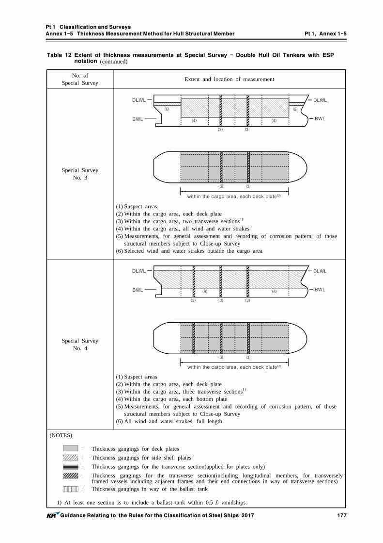
Pt 1 Classification and Surveys
Annex 1-5 Thickness Measurement Method for Hull Structural Member Pt 1, Annex 1-5
Guidance Relating to the Rules for the Classification of Steel Ships 2017 177
No. ofSpecial Survey
Extent and location of measurement
Special SurveyNo. 3
(1) Suspect areas(2) Within the cargo area, each deck plate(3) Within the cargo area, two transverse sections1)
(4) Within the cargo area, all wind and water strakes(5) Measurements, for general assessment and recording of corrosion pattern, of those
structural members subject to Close-up Survey(6) Selected wind and water strakes outside the cargo area
Special SurveyNo. 4
(1) Suspect areas(2) Within the cargo area, each deck plate(3) Within the cargo area, three transverse sections1)
(4) Within the cargo area, each bottom plate(5) Measurements, for general assessment and recording of corrosion pattern, of those
structural members subject to Close-up Survey(6) All wind and water strakes, full length
(NOTES)
Thickness gaugings for deck plates
Thickness gaugings for side shell plates
Thickness gaugings for the transverse section(applied for plates only)
Thickness gaugings for the transverse section(including longitudinal members, for transversely framed vessels including adjacent frames and their end connections in way of transverse sections)
Thickness gaugings in way of the ballast tank
1) At least one section is to include a ballast tank within 0.5 amidships.
Table 12 Extent of thickness measurements at Special Survey - Double Hull Oil Tankers with ESP notation (continued)

Pt 1 Classification and Surveys
Annex 1-5 Thickness Measurement Method for Hull Structural Member Pt 1, Annex 1-5
178 Guidance Relating to the Rules for the Classification of Steel Ships 2017
No. ofSpecial Survey
Extent and location of measurement
Special SurveyNo. 1
(1) Suspect areas
Special SurveyNo. 2
(1) Suspect areas(2) Within the cargo length, two transverse sections of deck plating outside line of car-
go hatch openings(3) Wind and water strakes in way of the two transverse sections considered (2) above(4) Selected wind and water strakes outside the cargo length area(5) Measurements, for general assessment and recording of corrosion pattern, of those
structural members subject to Close-up Survey
Special SurveyNo. 3
(1) Suspect areas(2) Within the cargo length, each deck plate outside line of cargo hatch openings(3) Within the cargo length, two transverse sections, one in the amidship area, outside
line of cargo hatch openings(4) Within the cargo length, all wind and water strakes(5) Selected wind and water strakes outside the cargo length area(6) Measurements, for general assessment and recording of corrosion pattern, of those
structural members subject to Close-up Survey
Table 13 Extent of thickness measurements at Special Survey - Double Skin Bulk Carriers with ESP notation
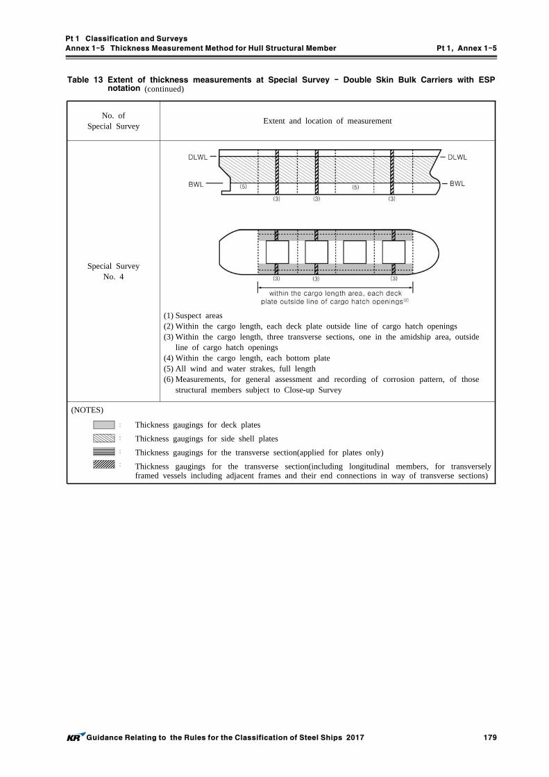
Pt 1 Classification and Surveys
Annex 1-5 Thickness Measurement Method for Hull Structural Member Pt 1, Annex 1-5
Guidance Relating to the Rules for the Classification of Steel Ships 2017 179
No. ofSpecial Survey
Extent and location of measurement
Special SurveyNo. 4
(1) Suspect areas(2) Within the cargo length, each deck plate outside line of cargo hatch openings(3) Within the cargo length, three transverse sections, one in the amidship area, outside
line of cargo hatch openings(4) Within the cargo length, each bottom plate(5) All wind and water strakes, full length(6) Measurements, for general assessment and recording of corrosion pattern, of those
structural members subject to Close-up Survey
(NOTES)
Thickness gaugings for deck plates
Thickness gaugings for side shell plates
Thickness gaugings for the transverse section(applied for plates only)
Thickness gaugings for the transverse section(including longitudinal members, for transversely framed vessels including adjacent frames and their end connections in way of transverse sections)
Table 13 Extent of thickness measurements at Special Survey - Double Skin Bulk Carriers with ESP notation (continued)

Pt 1 Classification and Surveys
Annex 1-5 Thickness Measurement Method for Hull Structural Member Pt 1, Annex 1-5
180 Guidance Relating to the Rules for the Classification of Steel Ships 2017
Table 14 Requirements for extent of thickness measurements at those areas of substantial corrosion - Bulk Carriers with ESP notation
1) Shell Structures
Structural Member Extent of Measurement Pattern of measurement
1. Bottom and Side Shell Plating
1) Suspect plate, plus four adjacent plates
2) See other tables for particulars on gauging in way tanks and cargo holds
1) 5 point pattern for each panel between longitudinals
2. Bottom/Side Shell Longitudinals
Minimum of three longitudinals in way of suspect areas
3 measurement in line across web3 measurement on flange
2) Transverse Bulkheads in Cargo Holds
Structural member Extent of Measurement Pattern of measurement
1. Lower Stool
1) Transverse band within 25 mm of welded connection to inner-bottom
2) Transverse band within 25 mm of welded connection to shelf plate
1) 5 point between stiffeners over 1 metre length2) 5 point between stiffeners over 1 metre length
2. Transverse Bulkhead
1) Transverse band at approximately mid height2) Transverse band at part of bulkhead adjacent to
upper deck or below upper stool shelf plate (for those ships fitted with upper stools)
1) 5 point pattern over 1 sq. metre of plating
2) 5 point pattern over 1 sq. metre of plating
3) Deck Structure including Cross Strips, Main Cargo Hatchways, Hatch Covers, Coamings and Topside Tanks
Structural Member Extent of Measurement Pattern of Measurement
1. Cross Deck Strip Plating
Suspect cross deck strip plating5 point pattern between underdeck stiffeners over 1 metre length
2. Underdeck Stiffeners
1) Transverse members2) Longitudinal member
1) 5 point pattern at each end and mid span2) 5 point pattern on both web and flange
3. Hatch Covers1) Side and end skirts, each 3 locations2) 3 longitudinal bands, outboard strakes
(2) and centerline strake (1)
1) 5 point pattern at each location2) 5 point measurement each band
4. Hatch Coamings
Each side and end of coaming, one band lower 1/3, one band upper 2/3 of coam-ing
5 point measurement each band i.e. end or side coaming
5. Topside Ballast Tanks
1) Watertight transverse bulkheadsa) lower 1/3 of bulkheadb) upper 2/3 of bulkheadc) stiffeners
2) 2 representative swash transverse bulk-headsa) lower 1/3 of bulkheadb) upper 2/3 of bulkheadc) stiffeners
3) 3 representative bays of slop platinga) lower 1/3 of tankb) upper 2/3 of tank
4) Longitudinals, suspect and adjacent
1)a) 5 point pattern over 1 sq. metre of platingb) 5 point pattern over 1 sq. metre of platingc) 5 point pattern over 1 metre length
2)a) 5 point pattern over 1 sq. metre of platingb) 5 point pattern over 1 sq. metre of platingc) 5 point pattern over 1 metre length
3)a) 5 point pattern over 1 sq. metre of platingb) 5 point pattern over 1 sq. metre of plating
4) 5 point pattern both web and flange over 1 metre length
6. Main Deck Plating
Suspect plates and adjacent (4) 5 point pattern over 1 sq. metre of plating
7. Main Deck Longitudinals
Minimum of 3 longitudinals where plat-ing measured
5 point pattern on both web and flange over 1 metre length
8. Web Frames /Transverses
Suspect plates 5 point pattern over 1 sq. metre

Pt 1 Classification and Surveys
Annex 1-5 Thickness Measurement Method for Hull Structural Member Pt 1, Annex 1-5
Guidance Relating to the Rules for the Classification of Steel Ships 2017 181
Table 14 Requirements for extent of thickness measurements at those areas of substantial corrosion - Bulk Carriers with ESP notation (continued)
4) Double Bottom and Hopper Structure
Structural Member Extent of Measurement Pattern of Measurement
1. Inner/Double Bottom Plating
Suspect plate plus all adjacent plates5 point pattern for each panel between longitudinals over 1 metre length
2. Inner/Double Bottom Longitudinals
Three longitudinals where plates measured3 measurements in line across web and3 measurements on flange
3. Longitudinal Girders or Transverse Floors
Suspect plates 5 point pattern over about 1 square metre
4. Watertight Bulkhead (W.T Floors)
1) lower 1/3 of tank2) upper 2/3 of tank
1) 5 point pattern over 1 sq. metre of plating2) 5 point pattern alternate plates over 1 sq.
metre of plating
5. Web Frames Suspect plating 5 point pattern over 1 sq. metre of plating
6. Bottom/Side Shell Longitudinals
Minimum of three longitudinals in way of suspect areas
3 measurements in line across web3 measurements on flange
5) Cargo Holds
Structural Member
Extent of Measurement Pattern of Measurement
1. Side Shell Frames
Suspect frame and each adjacent frame
a) At each end and mid span : 5 point pattern of both web and flangeb) 5 point pattern within 25 mm of welded attachment of both shell
and lower slope plate

Pt 1 Classification and Surveys
Annex 1-5 Thickness Measurement Method for Hull Structural Member Pt 1, Annex 1-5
182 Guidance Relating to the Rules for the Classification of Steel Ships 2017
Table 15 Requirements for extent of thickness measurements at those areas of substantial corrosion - Oil Tankers, Ore/Oil Ships, Etc. with ESP notation
1) Bottom Structure
Structural Member Extent of Measurement Pattern of Measurement
1. Bottom PlatingMinimum of 3 bays across tank including aft bay Measurements around and under all bell mouths
5 point pattern for each panel between longitudinals and webs
2. Bottom LongitudinalsMinimum of 3 longitudinals in each bay where bottom plating measured
3 measurements in line across flange and 3 measurements on vertically web
3. Bottom Girders and Brackets
At fore and aft transverse bulkhead bracket toes and in centre of tanks
Vertical line of single measurements on web plating with one measurement between each panel stiffener, or a minimum of three measurements.Two measurements across face flat.5 point pattern on girder/bulkhead brackets.
4. Bottom Transverse Webs
3 webs in bays where bottom plating measured, with measurements at both ends and middle
5 points pattern over 2 square metre areaSingle measurements on face flat
5. Panel Stiffening Where provided Single measurements
2) Deck Structure
Structural Member Extent of Measurement Pattern of Measurement
1. Deck Plating Two bands across tank Minimum of three measurements per plate per band
2. Deck LongitudinalsMinimum of 3 longitudinals in each of two bands
3 measurements in line vertically on webs, and 2 measurements on flange (if fitted)
3. Deck Girders and Brackets
At fore and aft transverse bulk-head, bracket toes and in centre of tanks
Vertical line of single measurements on web plating with one measurement between each panel stiffener, or a minimum of three measurements.Two measurements across face flat.5 point pattern on girder/bulkhead brackets.
4. Deck Transverse Webs
Minimum of two webs with measurements at middle and both ends of span
5 points pattern over about 2 square metre areasSingle measurements on face flat
5. Panel Stiffening Where provided Single measurement

Pt 1 Classification and Surveys
Annex 1-5 Thickness Measurement Method for Hull Structural Member Pt 1, Annex 1-5
Guidance Relating to the Rules for the Classification of Steel Ships 2017 183
Table 15 Requirements for extent of thickness measurements at those areas of substantial corrosion - Oil Tankers, Ore/Oil Ships, Etc. with ESP notation (continued)
3) Side Shell and Longitudinal Bulkheads
Structural Member Extent of Measurement Pattern of Measurement
1. Deckhead and Bottom Strakes, and Strakes in way of Stringer Platforms
Plating between each pair of longitudinals in a minimum of 3 bays
Single measurement
2. All Other StrakesPlating between every 3rd pair of longitudinals in same 3 bays
Single measurement
3. Longitudinals-deckhead and Bottom Strakes
Each longitudinal in same 3 bays3 measurements across web and 1 measurement on flange
4. Longitudinals - All OthersEvery third longitudinal in same 3 bays
3 measurements across web and 1 measurement on flange
5. Longitudinals - BracketMinimum of three at top middle and bottom of tank in same 3 bays
5 point pattern over area of bracket
6. Web Frames and Cross Ties3 webs with minimum of three loca-tions on each web, including in way of cross tie connections
5 point pattern over about 2 square metre area, plus single measurements on web frame and cross tie face flats
4) Transverse Bulkheads and Swash Bulkheads
Structural Member Extent of Measurement Pattern of Measurement
1. Deckhead and Bottom Strakes, and Strakes in way of Stringer Platforms
Plating between pair of stiffeners at three locations - approx. 1/4, 1/2 and 3/4 width of tank
5 points pattern between stiffeners over 1 meter length
2. All Other StrakesPlating between pair of stiffeners at middle location
Single measurement
3. Strakes in Corrugated Bulkheads
Plating for each change of scantling at centre of panel and a flange or fab-ricated connection
5 point pattern over about 1 square metre of plating
4. Stiffeners Minimum of three typical stiffeners
For web, 5 point pattern over span between bracket connections (2 meas-urements across web at each bracket connection, and one at centre of span)For flange, single measurements at each bracket toe and at centre of span
5. BracketsMinimum of three at top middle and bottom of tank
5 point pattern over areas of bracket
6. Deep Webs and Girdersmeasurements at toe of bracket and at centre of span
For web, 5 point pattern over about 1 square metre3 measurements across face flat
7. Stringer PlatformsAll stringers with measurements at both ends and middle
5 point pattern over 1 square metre of area plus single measurements near bracket toes and on face flats

Pt 1 Classification and Surveys
Annex 1-5 Thickness Measurement Method for Hull Structural Member Pt 1, Annex 1-5
184 Guidance Relating to the Rules for the Classification of Steel Ships 2017
Table 16 Requirements for extent of thickness measurements at those areas of substantial corrosion - Chemical Tankers with ESP notation
1) Bottom, Inner Bottom and Hopper Structure
Structure Member Extent of Measurement Pattern of Measurement
1. Bottom, Inner Bottom and Hopper Structure Plating
Minimum of three bays across double bottom tank, including aft bay. Measurements around and under all suction bell mouths
5-point pattern for each panel be-tween longitudinals and floors
2. Bottom, Inner Bottom and Hopper Structure Longitudinals
Minimum of three longitudinals in each bay where bottom plating measured
Three measurements in line across the flange and three measurements on vertical web
3. Bottom Girders, including the watertight ones
At fore and aft watertight floor and in centre of tanks
Vertical line of single measurements on girder plating with one measure-ment between each panel stiffener, or a minimum of three measurements.Two measurements across face flat where fitted.
4. Bottom Floors, including the watertight ones
Three floors in bays where bottom plat-ing measured, with measurements at both ends and middle
5-point pattern over two square me-tre area
5. Hopper Structure Web Frame Ring
Three floors in bays where bottom plat-ing measured
5-point pattern over one square me-tre of plating. Single measurements on flange
6. Hopper Structure Transverse Watertight Bulkhead or Swash Bulkhead
․ Lower 1/3 of the bulkhead․ 5-point pattern over one square
meter of plating
․ Upper 2/3 of the bulkhead․ 5-point pattern over two square
metre of plating
․ Stiffeners(minimum of three)
․ For web, 5-point pattern over span(two measurements across web at each end and one at centre of span)
․ For flange, single measurements at each end and centre of span
7. Panel Stiffening Where applicable Single measurements
2) Deck Structure
Structure Member Extent of Measurement Pattern of Measurement
1. Deck Plating Two transverse bands across tankMinimum of three measurements per plate per band
2. Deck LongitudinalsEvery third longitudinal in each two bands with a minimum of one longitudinal
Three measurements in line vertically on webs and two measurements on flange(if fitted)
3. Deck Girders and BracketsAt fore and aft transverse bulk-head, bracket toes and in centre of tanks
Vertical line of single measurements on web plating with one measure-ment between each panel stiffener, or a minimum of three measurements.Two measurements across flange.5 point pattern on girder/bulkhead brackets
4. Deck Transverse WebsMinimum of two webs, with measurements at both ends and middle of span
5-point pattern over one square me-tre area. Single measurements on flange
5. Vertical Web and Transverse Bulkhead in Wing Ballast Tank for double hull design(two metres from deck)
Minimum of two webs, and both transverse bulkheads
5-point pattern over one square me-tre area
6. Panel Stiffening Where applicable Single measurements

Pt 1 Classification and Surveys
Annex 1-5 Thickness Measurement Method for Hull Structural Member Pt 1, Annex 1-5
Guidance Relating to the Rules for the Classification of Steel Ships 2017 185
Table 16 Requirements for extent of thickness measurements at those areas of substantial corrosion - Chemical Tankers with ESP notation (continued)
3) Side Shell and Longitudinal Bulkheads
Structure Member Extent of Measurement Pattern of Measurement1. Side Shell and Longitudinal
Bulkhead Plating ․ Deckhead and Bottom
Strakes, and Strakes in way of Horizontal Girders
․ All Other Strakes
․ Plating between each pair of longitudinals in a minimum of three bays(along the tank)․ Plating between every third pair of longi-tudinals in same three bays
․ Single measurement
․ Single measurement
2. Side Shell and Longitudinal Bulkhead Longitudinals on:
․ Deckhead and Bottom Strakes
․ All Other Strakes
․ Each longitudinal in same three bays
․ Every third longitudinal in same three bays
․ 3 measurements across web and 1 measurement on flange․ 3 measurements across web and 1 measurement on flange
3. Longitudinals - BracketsMinimum of three at top, middle and bottom of tank in same three bays
5-point pattern over area of bracket
4. Vertical Web and Transverse Bulkheads of Double Side Tanks (excluding deckhead area):
․ Strakes in way of Horizontal Girders
․ Other Strakes
․ Minimum of two webs and both transverse bulkheads․ Minimum of two webs and both transverse bulkheads
․ 5-point pattern over approx. two square metre area․ Two measurements between each pair of vertical stiffeners
5. Web Frames and Cross Ties for Other Tanks than Double Side Tanks
Three webs with minimum of three locations on each web, including in way of cross tie connections and lower end bracket
5-point pattern over approx-imately two square metre area of webs, plus single measurements on flanges of web frame and cross ties
6. Horizontal Girders Plating on each girder in a minimum of three bays
Two measurements between each pair of longitudinal girder stiff-eners
7. Panel Stiffening Where applicable Single measurements
4) Transverse Watertight and Swash Bulkheads
Structure Member Extent of Measurement Pattern of Measurement
1. Upper and Lower Stool, where fitted
․ Transverse band within 25 mm of welded connection to inner bottom/deck plating․ Transverse band within 25 mm of welded connection to shelf plate
5-point pattern between stiffeners over one metre length
2. Deckhead and Bottom Strakes, and Strakes in way of Horizontal Stringers
Plating between pair of stiffeners at three locations: approximately 1/4, 1/2 and 3/4 width of tank
5-point pattern between stiffeners over one metre length
3. All Other Strakes Plating between pair of stiffeners at mid-dle location
Single measurement
4. Strakes in Corrugated Bulkheads
Plating for each change of scantling at centre of panel and at flange of fab-ricated connection
5-point pattern over about one square metre of plating
5. Stiffeners Minimum of three typical stiffeners
For web, 5-point pattern over span be-tween bracket connections (two meas-urements across web at each bracket connection and one at centre of span). For flange, single measurements at each bracket toe and at centre of span
6. BracketsMinimum of three at top, middle and bottom of tank 5-point pattern over area of bracket
7. Horizontal StringersAll stringers with measurements at both ends and middle
5-point pattern over one square metre area, plus single measurements near bracket toes and on flanges
8. Deep Webs and Girders Measurements at toe of bracket and at centre of span
For web, 5-point pattern over about one square metre. three measurements across face flat

Pt 1 Classification and Surveys
Annex 1-5 Thickness Measurement Method for Hull Structural Member Pt 1, Annex 1-5
186 Guidance Relating to the Rules for the Classification of Steel Ships 2017
Table 17 Requirements for extent of thickness measurements at those areas of substantial corrosion - Double Hull Oil Tankers with ESP notation
1) Bottom, Inner Bottom and Hopper Structure
Structural Member Extent of Measurement Pattern of Measurement
1. Bottom, Inner Bottom and Hopper Structure Plating
Minimum of three bays across double bottom tank, including aft bay.Measurements around and under all suc-tion bell mouths
5-point pattern for each panel between longitudinals and floors
2. Bottom, Inner Bottom and Hopper Structure Longitudinals
Minimum of three longitudinals in each bay where bottom plating measured
Three measurements in line across flange and three measurements on verti-cal web
3. Bottom Girders, including the watertight ones
At fore and aft watertight floors and in centre of tanks
Vertical line of single measurements on girder plating with one measurement be-tween each panel stiffener, or a mini-mum of three measurements
4. Bottom Floors, including the watertight ones
Three floors in bays where bottom plat-ing measured, with measurements at both ends and middle
5-point pattern over two square metre area
5. Hopper Structure Web Frame Ring
Three floors in bays where bottom plat-ing measured
5-point pattern over one square metre of plating. Single measurements on flange
6. Hopper Structure Transverse Watertight Bulkhead or Swash Bulkhead
․ Lower 1/3 of bulkhead∙ 5-point pattern over two square metre
of plating
․ Upper 2/3 of bulkhead․ 5-point pattern over two square metre
of plating
․Stiffeners (minimum of three)
․ For web, 5-point pattern over span (two measurements across web at each end and one at centre of span).
․ For flange, single measurements at each end and centre of span
7. Panel Stiffening Where applicable Single measurements
2) Deck Structure
Structural Member Extent of Measurement Pattern of Measurement
1. Deck Plating Two transverse bands across tankMinimum of three measurements per plate per band
2. Deck LongitudinalsEvery third longitudinal in each of two bands with a minimum of one longi-tudinal
Three measurements in line vertically on webs and two measurements on flange (if fitted)
3. Deck Girders and Brackets (usually in cargo tanks only)
At fore and aft transverse bulkhead, bracket toes and in centre of tanks
Vertical line of single measurements on web plating with one measurement be-tween each panel stiffener, or a minimum of three measurements.Two measurements across flange. 5-point pattern on girder/bulkhead brackets
4. Deck Transverse WebsMinimum of two webs, with measure-ments at both ends and middle of span
5-point pattern over one square metre area. Single measurements on flange
5. Vertical Web and Transverse Bulkhead in Wing Ballast Tank (two metres from deck)
Minimum of two webs, and both trans-verse bulkheads
5-point pattern over one square metre area
6. Panel Stiffening Where applicable Single measurements

Pt 1 Classification and Surveys
Annex 1-5 Thickness Measurement Method for Hull Structural Member Pt 1, Annex 1-5
Guidance Relating to the Rules for the Classification of Steel Ships 2017 187
Table 17 Requirements for extent of thickness measurements at those areas of substantial corrosion - Double Hull Oil Tankers with ESP notation (continued)
3) Structure in Wing Ballast Tanks
Structural Member Extent of Measurement Pattern of Measurement
1. Side Shell and Longitudinal Bulkhead Plating :․ Upper Strake and Strakes in
way of Horizontal Girders․ All Other Strakes
․ Plating between each pair of longi-tudinals in a minimum of three bays (along the tank)
․ Plating between every third pair of longitudinals in same three bays
․ Single measurement
․ Single measurement
2. Side Shell and Longitudinal Bulkhead Longitudinals on :․ Upper Strake
․ All Other Strakes
․ Each longitudinal in same three bays
․ Every third longitudinal in same three bays
․ 3 measurements across web and 1 measurement on flange
․ 3 measurements across web and 1 measurement on flange
3. Longitudinals - BracketsMinimum of three at top, middle and bottom of tank in same three bays
5-point pattern over area of bracket
4. Vertical Web and Transverse Bulkheads (excluding deck-head area) :․ Strakes in way of
Horizontal Girders․ Other Strakes
․ Minimum of two webs and both transverse bulkheads
․ Minimum of two webs and both transverse bulkheads
․ 5-point pattern over approx. two square metre area
․ two measurement between each pair of vertical stiffeners
5. Horizontal GirdersPlating on each girder in a minimum of three bays
Two measurements between each pair of longitudinal girder stiffeners
6. Panel Stiffening Where applicable Single measurements
4) Longitudinal Bulkheads in Cargo Tanks
Structural Member Extent of Measurement Pattern of Measurement
1. Deckhead and Bottom Strakes, and Strakes in way of the Horizontal Stringers of Transverse Bulkheads
Plating between each pair of longi-tudinal in a minimum of three bays
Single measurement
2. All Other StrakesPlating between every third pair of lon-gitudinals in same three bays
Single measurement
3. Longitudinals on Deckhead and Bottom Strakes
Each longitudinal in same three baysThree measurements across web and one measurement on flange
4. All Other LongitudinalsEvery third longitudinal in same three bays
Three measurements across web and one measurement on flange
5. Longitudinals - BracketsMinimum of three at top, middle and bottom of tank in same three bays
5-point pattern over area of bracket
6. Web Frames and Cross TiesThree webs with minimum of three lo-cations on each web, including in way of cross tie connections
5-point pattern over approximately two square metre area of webs, plus single measurements on flanges of web frame and cross ties
7. Lower End Brackets (opposite side of web frame)
Minimum of three brackets
5-point pattern over approximately two square metre area of brackets, plus single measurements on bracket flang-es
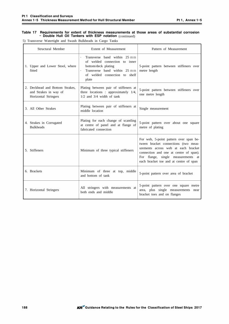
Pt 1 Classification and Surveys
Annex 1-5 Thickness Measurement Method for Hull Structural Member Pt 1, Annex 1-5
188 Guidance Relating to the Rules for the Classification of Steel Ships 2017
Table 17 Requirements for extent of thickness measurements at those areas of substantial corrosion - Double Hull Oil Tankers with ESP notation (continued)
5) Transverse Watertight and Swash Bulkheads in Cargo Tanks
Structural Member Extent of Measurement Pattern of Measurement
1. Upper and Lower Stool, where fitted
․ Transverse band within 25 mmof welded connection to inner bottom/deck plating
․ Transverse band within 25 mmof welded connection to shelf plate
5-point pattern between stiffeners over metre length
2. Deckhead and Bottom Strakes, and Strakes in way of Horizontal Stringers
Plating between pair of stiffeners at three locations : approximately 1/4, 1/2 and 3/4 width of tank
5-point pattern between stiffeners over one metre length
3. All Other StrakesPlating between pair of stiffeners at middle location
Single measurement
4. Strakes in Corrugated Bulkheads
Plating for each change of scantling at centre of panel and at flange of fabricated connection
5-point pattern over about one square metre of plating
5. Stiffeners Minimum of three typical stiffeners
For web, 5-point pattern over span be-tween bracket connections (two meas-urements across web at each bracket connection and one at centre of span). For flange, single measurements at each bracket toe and at centre of span
6. Brackets Minimum of three at top, middle and bottom of tank
5-point pattern over area of bracket
7. Horizontal StringersAll stringers with measurements at both ends and middle
5-point pattern over one square metre area, plus single measurements near bracket toes and on flanges
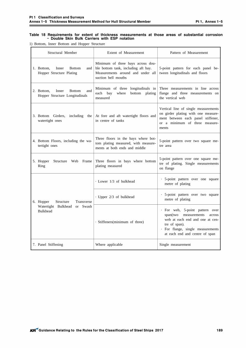
Pt 1 Classification and Surveys
Annex 1-5 Thickness Measurement Method for Hull Structural Member Pt 1, Annex 1-5
Guidance Relating to the Rules for the Classification of Steel Ships 2017 189
Table 18 Requirements for extent of thickness measurements at those areas of substantial corrosion - Double Skin Bulk Carriers with ESP notation
1) Bottom, Inner Bottom and Hopper Structure
Structural Member Extent of Measurement Pattern of Measurement
1. Bottom, Inner Bottom and Hopper Structure Plating
Minimum of three bays across dou-ble bottom tank, including aft bay.Measurements around and under all suction bell mouths
5-point pattern for each panel be-tween longitudinals and floors
2. Bottom, Inner Bottom and Hopper Structure Longitudinals
Minimum of three longitudinals in each bay where bottom plating measured
Three measurements in line across flange and three measurements on the vertical web
3. Bottom Girders, including the watertight ones
At fore and aft watertight floors and in centre of tanks
Vertical line of single measurements on girder plating with one measure-ment between each panel stiffener, or a minimum of three measure-ments
4. Bottom Floors, including the wa-tertight ones
Three floors in the bays where bot-tom plating measured, with measure-ments at both ends and middle
5-point pattern over two square me-tre area
5. Hopper Structure Web Frame Ring
Three floors in bays where bottom plating measured
5-point pattern over one square me-tre of plating. Single measurements on flange
6. Hopper Structure Transverse Watertight Bulkhead or Swash Bulkhead
․ Lower 1/3 of bulkhead ․ 5-point pattern over one square
metre of plating
․ Upper 2/3 of bulkhead ․ 5-point pattern over two square
metre of plating
․ Stiffeners(minimum of three)
․ For web, 5-point pattern over span(two measurements across web at each end and one at cen-tre of span).
․ For flange, single measurements at each end and centre of span
7. Panel Stiffening Where applicable Single measurement

Pt 1 Classification and Surveys
Annex 1-5 Thickness Measurement Method for Hull Structural Member Pt 1, Annex 1-5
190 Guidance Relating to the Rules for the Classification of Steel Ships 2017
Table 18 Requirements for extent of thickness measurements at those areas of substantial corrosion - Double Skin Bulk Carriers with ESP notation (continued)
2) Deck Structure including Cross Strips, Main Cargo Hatchways, Hatch Covers, Coamings and Topside Tanks
Structural Member Extent of Measurement Pattern of Measurement
1. Cross Deck Strip Plating
Suspect cross deck strip plating5-point pattern between underdeck stiffeners over 1 metre length
2. Underdeck Stiffeners
1) Transverse members2) Longitudinal members
1) 5-point pattern at each end and mid span2) 5-point pattern on both web and flange
3. Hatch Covers1) Side and end skirts, each three locations2) Three longitudinal bands, outboard
strakes(2) and centerline strake(1)
1) 5-point pattern at each location2) 5-point measurement each band
4. Hatch CoamingsEach side and end of coaming, one band lower 1/3, one band upper 2/3 of coaming
5-point measurement each band i.e. end or sid coaming
5. Topside Ballast Tanks
1) Watertight transverse bulkhead a) Lower 1/3 of bulkhead b) Upper 2/3 of bulkhead c) Stiffeners2) Two representative swash transverse
bulkheads a) Lower 1/3 of bulkhead b) Upper 2/3 of bulkhead c) Stiffeners3) Three representative bays of slope plating a) Lower 1/3 of tank b) Upper 2/3 of tank4) Longitudinals, suspect and adjacent
1) a) 5-point pattern over 1 sq. metre of plating b) 5-point pattern over 1 sq. metre of plating c) 5-point pattern over 1 metre length2)
a) 5-point pattern over 1 sq. metre of plating b) 5-point pattern over 1 sq. metre of plating c) 5-point pattern over 1 metre length3) a) 5-point pattern over 1 sq. metre of plating b) 5-point pattern over 1 sq. metre of plating4) 5-point pattern on both web and flange over
1 metre length
6. Main Deck Plating
Suspect plates and adjacent(4) 5-point pattern over 1 sq. metre of plating
7. Main Deck Longitudinals
Suspect plates5-point pattern on both web and flange over 1 metre length
8. Web Frames/ Transverse
Suspect plates 5-point pattern over 1 sq. metre of plating

Pt 1 Classification and Surveys
Annex 1-5 Thickness Measurement Method for Hull Structural Member Pt 1, Annex 1-5
Guidance Relating to the Rules for the Classification of Steel Ships 2017 191
Table 18 Requirements for extent of thickness measurements at those areas of substantial corrosion - Double Skin Bulk Carriers with ESP notation (continued)
3) Structure in Double Side Spaces(including Wing Void Spaces of Ore Carriers)
Structural Member Extent of Measurement Pattern of Measurement
1. Side Shell and Inner Plating : ․ Upper strake and strakes in way of horizontal girders
․ All other strakes
․ Plating between each pair of trans-verse frames/longitudinals in a mini-mum of three bays(along the tank)
․ Plating between every third pair of longitudinals in same three bays
․ Single measurements
․ Single measurements
2. Side Shell and Inner Side Transverse Frames/ Longitudinals on : ․ Upper strake
․ All other strakes
․ Each transverse frame/longitudinal in same three bays
․ Every third transverse frame/longi-tudinal in same three bays
․ Three measurements across web and 1 measurement on flange
․ Three measurements across web and 1 measurement on flange
3. Transverse Frames/Longitudinals Brackets
Minimum of three at top, middle and bottom of tank in same three bays
5-point pattern over area of bracket
4. Vertical Web and Transverse Bulkheads : ․ Strakes in way of horizontal girders ․ Other strakes
․ Minimum of two webs and both transverse bulkheads
․ Minimum of two webs and both transverse bulkheads
․ 5-point patterns over approx. two square metre area
․ Two measurements between each pair of vertical stiffeners
5. Horizontal GirdersPlating on each girder in a minimum of three bays
Two measurements between each pair of longitudinal girder stiffeners
6. Panel Stiffening Where applicable Single measurements
4) Transverse Bulkheads in Cargo Holds
Structural Member Extent of Measurement Pattern of Measurement
1. Lower Stool, where fitted
․ Transverse band within 25 mm of welded connection to inner bottom
․ Transverse band within 25 mm of welded connection to shelf plate
․ 5-point pattern between stiff-eners over one metre length
․ 5-point pattern between stiff-eners over one metre length
2. Transverse Bulkheads
․ Transverse band at approximately mid height
․ Transverse band at part of bulkhead adjacent to upper deck of below upper stool shelf plate(for those ships fitted with upper stools)
․ 5-point pattern over one square metre of plating
․ 5-point pattern over one square metre of plating

Pt 1 Classification and Surveys
Annex 1-5 Thickness Measurement Method for Hull Structural Member Pt 1, Annex 1-5
192 Guidance Relating to the Rules for the Classification of Steel Ships 2017
Table 19 General Particulars
GENERAL PARTICULARS
Ship’s name :
IMO Number :
Class Identification number :
Port of registry :
Gross tons :
Deadweight :
Date of build :
Classification society :
Name of Company performing thickness measurement :
Thickness measurement company certified by :
Certificate No. :
Certificate valid from to
Place of measurement :
First date of measurement :
Last date of measurement :
Special survey/intermediate survey due :*
Details of measurement equipment :
Qualification of operator :
Report Number : consisting of Sheets
Name of operator : Name of surveyor :
Signature of operator : Signature of surveyor :
Company official stamp : Classification Society
Official Stamp :
* Delete as appropriate

Pt 1 Classification and Surveys
Annex 1-5 Thickness Measurement Method for Hull Structural Member Pt 1, Annex 1-5
Guidance Relating to the Rules for the Classification of Steel Ships 2017 193
Table 20-1 Thickness measurements reports - Non-CSR Ships
Table 20-1 is to be used to vessels not built under IACS Common Structural Rules(Pt 11, Pt 12 or Pt 13)(i.e. Non-CSR Ships)
TM1-T/DHT/BC/DSBC/GE*
Report on THICKNESS MEASUREMENT of ALL DECK PLATING / ALL BOTTOM SHELL PLATING / ALL SIDE SHELL PLATING*
Ship's Name : Class Identity No. : Report No. :STRAKE
POSITION
PLATEPOSITION
No. or Letter
Org. Thk.mm
Forward Reading Aft Reading Mean Diminution %
M.A.DGauged Diminution P Diminution S Gauged Diminution P Diminution S
P S mm % mm % P S mm % mm % P S mm
15th forward
14th
13th
12th
11th
10th
9th
8th
7th
6th
5th
4th
3rd
2nd
1st
Amidships
1st aft
2nd
3rd
4th
5th
6th
7th
8th
9th
10th
11th
12th
13th
14th
15th
Operators Signature :
(NOTES) 1. This report form is to be used for recording the thickness measurement of :
All strength deck plating within the cargo (length) areaAll keel, bottom shell plating and bilge plating within the cargo (length) areaSide shell plating including selected wind and water strakes outside cargo (length) areaAll wind and water strakes within cargo (length) area
2. The strake position is to be clearly indicated as follow :2.1 For strength deck indicate the number of the strake of plating inboard from the stringer plate.2.2 For bottom plating indicate the number of the strake of plating outboard from the keel plate.2.3 For side shell plating give number of the strake of plating below sheerstrake and letter as shown on shell expansion.
3. For the ships which have no wide cargo openings i.e oil tankers all deck plating strakes are to be recorded, for the ships which have wide cargo openings i.e ore/oil ships and bulk carriers only the deck plating strakes outside line of openings are to be recorded. 4. Measurements are to be taken at the forward and aft areas of all plates and where plates cross ballast and cargo
tank/hold boundaries separate measurements for the area of plating in way of each type of tank/hold are to be recorded. 5. The single measurements recorded are to represent the average of multiple measurements. 6. The maximum allowable diminution could be stated in an attached document.
* : delete as appropriate T : Oil Tankers and Chemical Tankers with ESP notation DHT : Double Hull Oil Tankers with ESP notation BC : Bulk Carriers with ESP notation DSBC : Double Skin Bulk Carriers with ESP notation GE : Others M.A.D : Maximum Allowable Diminution
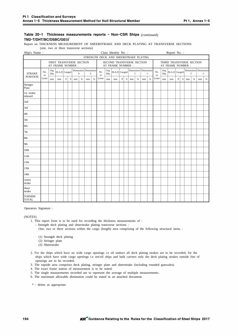
Pt 1 Classification and Surveys
Annex 1-5 Thickness Measurement Method for Hull Structural Member Pt 1, Annex 1-5
194 Guidance Relating to the Rules for the Classification of Steel Ships 2017
Table 20-1 Thickness measurements reports - Non-CSR Ships (continued)TM2-T/DHT/BC/DSBC/GE(i)
*
Report on THICKNESS MEASUREMENT OF SHEERSTRAKE AND DECK PLATING AT TRANSVERSE SECTIONS (one, two or three transverse sections)
Ship's Name : Class Identity No. : Report No. :
STRENGTH DECK AND SHEERSTRAKE PLATING
FIRST TRANSVERSE SECTION AT FRAME NUMBER :
SECOND TRANSVERSE SECTION AT FRAME NUMBER :
THIRD TRANSVERSE SECTION AT FRAME NUMBER :
STRAKEPOSITION
No.or
Letter
Org.Thk.
M.A.D GaugedDiminution
PDiminution
SNo.or
Letter
Org.Thk.
M.A.D GaugedDiminution
PDiminution
S No.or
Letter
Org.Thk.
M.A.D GaugedDiminution
PDiminution
Smm mm P S mm % mm % mm mm P S mm % mm % mm mm P S mm % mm %
StringerPlate
1st strakeinboard
2nd
3rd
4th
5th
6th
7th
8th
9th
10th
11th
12th
13th
14th
centrestrake
sheerstrake
TOPSIDETOTAL
Operators Signature :
(NOTES) 1. This report form is to be used for recording the thickness measurements of : - Strength deck plating and sheerstrake plating transverse sections : One, two or three sections within the cargo (length) area comprising of the following structural items :
(1) Strength deck plating (2) Stringer plate (3) Sheerstrake
2. For the ships which have no wide cargo openings i.e oil tankers all deck plating strakes are to be recorded, for the ships which have wide cargo openings i.e ore/oil ships and bulk carriers only the deck plating strakes outside line of openings are to be recorded. 3. The topside area comprises deck plating, stringer plate and sheerstrake (including rounded gunwales) 4. The exact frame station of measurement is to be stated. 5. The single measurements recorded are to represent the average of multiple measurements. 6. The maximum allowable diminution could be stated in an attached document.
* : delete as appropriate

Pt 1 Classification and Surveys
Annex 1-5 Thickness Measurement Method for Hull Structural Member Pt 1, Annex 1-5
Guidance Relating to the Rules for the Classification of Steel Ships 2017 195
Table 20-1 Thickness measurements reports - Non-CSR Ships (continued)TM2-T/DHT/BC/DSBC/GE(ii)
*
Report on THICKNESS MEASUREMENT OF SHELL AND BOTTOM PLATING AT TRANSVERSE SECTIONS (one, two or three transverse sections)
Ship's Name : Class Identity No. : Report No. :
SHELL AND BOTTOM PLATING
FIRST TRANSVERSE SECTION AT FRAME NUMBER :
SECOND TRANSVERSE SECTION AT FRAME NUMBER :
THIRD TRANSVERSE SECTION AT FRAME NUMBER :
STRAKE POSITION
No.or
Letter
Org.Thk.
M.A.D GaugedDiminution
PDiminution
SNo.or
Letter
Org.Thk.
M.A.D GaugedDiminution
PDiminution
S No.or
Letter
Org.Thk.
M.A.D GaugedDiminution
PDiminution
Smm mm P S mm % mm % mm mm P S mm % mm % mm mm P S mm % mm %
1st belowsheerstrake
2nd
3rd
4th
5th
6th
7th
8th
9th
10th
11th
12th
13th
14th
15th
16th
17th
18th
19th
20th
keel strake
BOTTOMTOTAL
Operators Signature :
(NOTES)
1. This report form is to be used for recording the thickness measurements of :
- Shell and bottom plating transverse sections :
One, two or three sections within the cargo (length) area comprising of the following structural items :
(1) Side shell plating
(2) Bilge plating
(3) Bottom shell plating
(4) Keel plate
2. The bottom area comprises keel, bottom and bilge plating.
3. The exact frame station of measurement is to be stated.
4. The single measurements recorded are to represent the average of multiple measurements.
5. The maximum allowable diminution could be stated in an attached document.
* : delete as appropriate

Pt 1 Classification and Surveys
Annex 1-5 Thickness Measurement Method for Hull Structural Member Pt 1, Annex 1-5
196 Guidance Relating to the Rules for the Classification of Steel Ships 2017
Table 20-1 Thickness measurements reports - Non-CSR Ships (continued)TM3-T/DHT/BC/DSBC/GE
*
Report on THICKNESS MEASUREMENT OF LONGITUDINAL MEMBERS AT TRANSVERSE SECTIONS (one, two or three transverse sections)
Ship's Name : Class Identity No. : Report No. :FIRST TRANSVERSE SECTION
AT FRAME NUMBER :SECOND TRANSVERSE SECTION
AT FRAME NUMBER :THIRD TRANSVERSE SECTION
AT FRAME NUMBER :
STRUCTUREMEMBER
Item No.
Org.Thk.
M.A.D GaugedDiminution
PDiminution
SItem No.
Org.Thk.
M.A.D GaugedDiminution
PDiminution
SItem No.
Org.Thk.
M.A.D GaugedDiminution
PDiminution
S
mm mm P S mm % mm % mm mm P S mm % mm % mm mm P S mm % mm %
Operators Signature :
(NOTES) 1. This report form is to be used for recording the thickness measurements of : - Longitudinal members at transverse sections : One, two or three sections within the cargo (length) area comprising of the following structural items :
(1) Deck longitudinals (2) Deck girders (3) Sheerstrake longitudinals (4) Longitudinal bulkhead top strake (5) Bottom longitudinals (6) Bottom girders (7) Bilge longitudinals (8) Longitudinal bulkhead lower strake (9) Side shell longitudinals (10) Longitudinal bulkhead plating (remainder) (11) Longitudinal bulkhead longitudinals (12) Inner bottom plating (13) Inner bottom longitudinals (14) Topside tank sloping plating (15) Topside tank sloping plating longitudinals (16) Hopper side plating (17) Hopper side longitudinals (18) 2nd deck plating (including all lower decks) (19) 2nd deck plating longitudinals (including all lower decks) (20) 2nd deck girders (including all lower decks) (21) Horizontal girders in wing ballast tanks (22) Inner side plating (23) Inner side longitudinals
2. The exact frame station of measurement is to be stated. 3. The single measurements recorded are to represent the average of multiple measurements. 4. The maximum allowable diminution could be stated in an attached document.
* : delete as appropriate
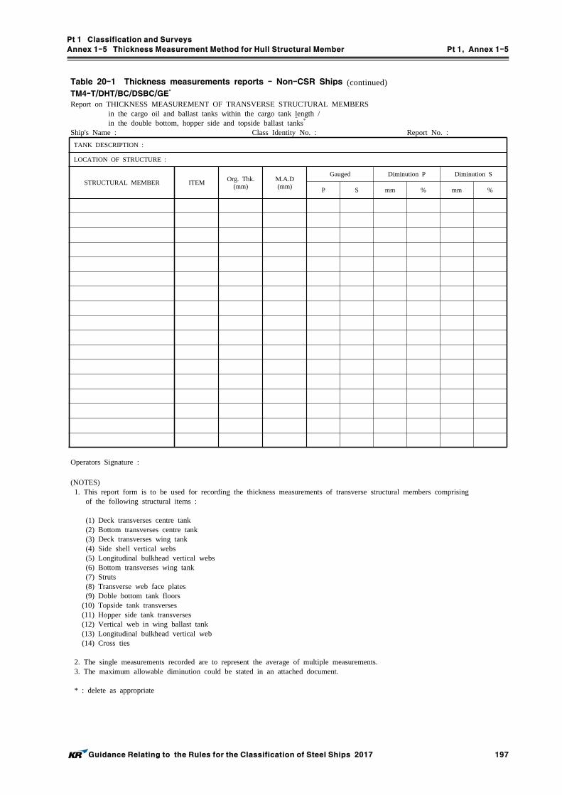
Pt 1 Classification and Surveys
Annex 1-5 Thickness Measurement Method for Hull Structural Member Pt 1, Annex 1-5
Guidance Relating to the Rules for the Classification of Steel Ships 2017 197
Table 20-1 Thickness measurements reports - Non-CSR Ships (continued)TM4-T/DHT/BC/DSBC/GE
*
Report on THICKNESS MEASUREMENT OF TRANSVERSE STRUCTURAL MEMBERS in the cargo oil and ballast tanks within the cargo tank length / in the double bottom, hopper side and topside ballast tanks*
Ship's Name : Class Identity No. : Report No. :
TANK DESCRIPTION :
LOCATION OF STRUCTURE :
STRUCTURAL MEMBER ITEMOrg. Thk.
(mm)M.A.D(mm)
Gauged Diminution P Diminution S
P S mm % mm %
Operators Signature :
(NOTES) 1. This report form is to be used for recording the thickness measurements of transverse structural members comprising of the following structural items :
(1) Deck transverses centre tank (2) Bottom transverses centre tank (3) Deck transverses wing tank (4) Side shell vertical webs (5) Longitudinal bulkhead vertical webs (6) Bottom transverses wing tank (7) Struts (8) Transverse web face plates (9) Doble bottom tank floors (10) Topside tank transverses (11) Hopper side tank transverses (12) Vertical web in wing ballast tank (13) Longitudinal bulkhead vertical web (14) Cross ties
2. The single measurements recorded are to represent the average of multiple measurements. 3. The maximum allowable diminution could be stated in an attached document.
* : delete as appropriate

Pt 1 Classification and Surveys
Annex 1-5 Thickness Measurement Method for Hull Structural Member Pt 1, Annex 1-5
198 Guidance Relating to the Rules for the Classification of Steel Ships 2017
Table 20-1 Thickness measurements reports - Non-CSR Ships (continued)TM5-T/DHT/BC/DSBC/GE
*
Report on THICKNESS MEASUREMENT OF W.T/O.T TRANSVERSE BULKHEADS within the cargo tanks/holds and ballast tanksShip's Name : Class Identity No. : Report No. :
TANK/HOLD DESCRIPTION :
LOCATION OF STRUCTURE :
FRAME NO:
STRUCTURAL COMPONENT (PLATING/STIFFENER)
Org. Thk.(mm)
M.A.D(mm)
Gauged Diminution P Diminution S
P S mm % mm %
Operators Signature :
(NOTES)
1. This report form is to be used for recording the thickness measurement of W.T / O.T transverse bulkheads or
cargo hold transverse bulkheads including bulkhead stiffeners and internal stiffeners of upper and lower stools.
2. The single measurements recorded are represent the average of multiple measurements.
3. The maximum allowable diminution could be stated in an attached document.
* : delete as appropriate

Pt 1 Classification and Surveys
Annex 1-5 Thickness Measurement Method for Hull Structural Member Pt 1, Annex 1-5
Guidance Relating to the Rules for the Classification of Steel Ships 2017 199
Table 20-1 Thickness measurements reports - Non-CSR Ships (continued)TM6-T/DHT/BC/DSBC/GE
*
Report on THICKNESS MEASUREMENT OF MISCELLANEOUS STRUCTURAL MEMBERS
Ship's Name : Class Identity No. : Report No. :
STRUCTURAL MEMBER : SKETCH
LOCATION OF STRUCTURE :
DescriptionOrg. Thk.
(mm)M.A.D(mm)
Gauged Diminution P Diminution S
P S mm % mm %
Operators Signature :
(NOTES)
1. This report form is to be used for recording the thickness measurement of miscellaneous structural members including
the following structural items :
(1) Hatch coamings (including stiffeners)
(2) Deck plating between hatches
(3) Hatch covers (including stiffeners)
(4) Inner bulkhead plating
(5) Superstructure deck plating
(6) Forepeak tank internal members
(7) Aftpeak tank internal members
2. The single measurements recorded are to represent the average of multiple measurements.
3. The maximum allowable diminution could be stated in an attached document.
* : delete as appropriate

Pt 1 Classification and Surveys
Annex 1-5 Thickness Measurement Method for Hull Structural Member Pt 1, Annex 1-5
200 Guidance Relating to the Rules for the Classification of Steel Ships 2017
Table 20-1 Thickness measurements reports - Non-CSR Ships (continued)TM8-BC/S31
Report on THICKNESS MEASUREMENT OF CARGO HOLD SIDE SHELL FRAMES
Ship's Name : Class Identity No. : Report No. :
CARGO HOLD NO. :
ZONE A ZONE B ZONE C ZONE D
FrameNo.
Org.Thk.
tREN tCOAT tM Diminution Org.Thk.
tREN tCOAT tM DiminutionOrg.Thk.
tREN tCOAT tM Diminution Org.Thk.
tREN tCOAT tM Diminution
mm mm mm mm mm % mm mm mm mm mm % mm mm mm mm mm % mm mm mm mm mm %
Operators Signature :
(NOTES)
1. This report is to be used for recording the thickness measurement of Cargo Hold Transverse Frames for application of UR S31
2. The gauging pattern for zones A, B & D are to be a five point pattern and for zone C may be measured by taking 3
reading over the length of zone C. If the web plating of zone C has general corrosion then it should be expanded to a
five pattern. The gauging pattern is to be over the depth web and the same area vertically. The gauging report is to
reflect the average reading.
h
0.25h
0.25hX
X
X
X
X
X
X
X
A Zone
B Zone
C Zone
D ZoneX X
X
X X
side shell face plate
Typical 5 point pattern
Typical Transverse Frame Non - Typical Transverse Frame

Pt 1 Classification and Surveys
Annex 1-5 Thickness Measurement Method for Hull Structural Member Pt 1, Annex 1-5
Guidance Relating to the Rules for the Classification of Steel Ships 2017 201
Table 20-1 Thickness measurements reports - Non-CSR Ships (continued)TM7-BC/GE
*
Report on THICKNESS MEASUREMENT OF CARGO HOLD TRANSVERSE FRAMES
Ship's Name : Class Identity No. : Report No. :
CARGO HOLD NO. :
UPPER PART MID PART LOWER PART
FRAMENUMBER
Org.Thk.
M.A.D GaugedDiminution
PDiminution
SOrg.Thk.
M.A.D GaugedDiminution
PDiminution
SOrg.Thk.
M.A.D GaugedDiminution
PDiminution
S
mm mm P S mm % mm % mm mm P S mm % mm % mm mm P S mm % mm %
Operators Signature :
(NOTES)
1. This report form is to be used for recording the thickness measurement of :
Cargo hold transverse frames or diaphragms
2. The location and pattern of measurements is to be indicated on the sketches of hold frames shown below.
3. The single measurements recorded are to represent the average of multiple measurements.
4. The maximum allowable diminution could be stated in an attached document.
* : delete as appropriate

Pt 1 Classification and Surveys
Annex 1-5 Thickness Measurement Method for Hull Structural Member Pt 1, Annex 1-5
202 Guidance Relating to the Rules for the Classification of Steel Ships 2017
Table 20-2 Thickness measurements reports - CSR Ships
Table 20-2 is to be used to vessels built under IACS Common Structural Rules(Pt 11, Pt 12 or Pt 13)(i.e. CSR Ships)
TM1-DHT/BC/DSBC*(CSR)
Report on THICKNESS MEASUREMENT of ALL DECK PLATING / ALL BOTTOM PLATING / ALL SIDE SHELL PLATING*
Ship's Name : Class Identity No. : Report No. :STRAKE
POSITION
PLATEPOSITION
No.or
Letter
AsBuiltThk.mm
VoluntaryThicknessAddition
mm
RenewalThickness
mm(a)
Forward Reading Aft Reading Mean Remaining Corr.
Addition, mm[(c1)+(c2)]/2
GaugedThk. mm
(b1)
Remaining Corr.Addition, mm(c1)=(b1)-(a)
GaugedThk. mm
(b2)
Remaining Corr.Addition, mm(c2)=(b2)-(a)
P S P S P S P S P S
15th forward
14th
13th
12th
11th
10th
9th
8th
7th
6th
5th
4th
3rd
2nd
1st
Amidships
1st aft
2nd
3rd
4th
5th
6th
7th
8th
9th
10th
11th
12th
13th
14th
15th
Operators Signature :
(NOTES) 1. This report form is to be used for recording the thickness measurement of :
All strength deck plating within the cargo (length) areaAll keel, bottom shell plating and bilge plating within the cargo (length) areaSide shell plating including selected wind and water strakes outside cargo (length) areaAll wind and water strakes within cargo (length) area
2. The strake position is to be clearly indicated as follow :2.1 For strength deck indicate the number of the strake of plating inboard from the stringer plate.2.2 For bottom plating indicate the number of the strake of plating outboard from the keel plate.2.3 For side shell plating give number of the strake of plating below sheerstrake and letter as shown on shell expansion.
3. For BC/DSBC(CSR), only the deck plating strakes outside line of openings are to be recorded. 4. Measurements are to be taken at the forward and aft areas of all plates and where plates cross ballast and cargo
tank/hold boundaries separate measurements for the area of plating in way of each type of tank/hold are to be recorded. 5. The single measurements recorded are to represent the average of multiple measurements. 6. The remaining corrosion addition is to be recorded with result of gauged thickness minus renewal thickness. If the result is negative, the structure in way shall be renewed, and the mark "R" is to be indicated in the right-hand column. If the result is between 0 and 0.5 mm (0 included), the structure in way shall be additional gauged, and the mark "S" is to be indicated in the right-hand column.
* : delete as appropriate DHT : Double Hull Oil Tankers with ESP notation BC : Bulk Carriers with ESP notation DSBC : Double Skin Bulk Carriers with ESP notation

Pt 1 Classification and Surveys
Annex 1-5 Thickness Measurement Method for Hull Structural Member Pt 1, Annex 1-5
Guidance Relating to the Rules for the Classification of Steel Ships 2017 203
Table 20-2 Thickness measurements reports - CSR Ships (continued)TM2-DHT/BC/DSBC
*(CSR)(i)
Report on THICKNESS MEASUREMENT OF SHEERSTRAKE AND DECK PLATING AT TRANSVERSE SECTIONS (one, two or three transverse sections)
Ship's Name : Class Identity No. : Report No. :
STRENGTH DECK AND SHEERSTRAKE PLATING
FIRST TRANSVERSE SECTION AT FRAME NUMBER :
SECOND TRANSVERSE SECTION AT FRAME NUMBER :
THIRD TRANSVERSE SECTION AT FRAME NUMBER :
STRAKEPOSITION
No.or
Letter
AsBuiltThk.mm
Vol.Thk.Add.mm
Ren.Thk.mm(a)
GaugedThk.mm(b)
Remaining Corr.Addition, mm
(b)-(a)
No.or
Letter
AsBuiltThk.mm
Vol.Thk.Add.mm
Ren.Thk.mm(a)
GaugedThk.mm(b)
Remaining Corr.Addition, mm
(b)-(a)
No.or
Letter
AsBuiltThk.mm
Vol.Thk.Add.mm
Ren.Thk.mm(a)
GaugedThk.mm(b)
Remaining Corr.Addition, mm
(b)-(a)
P S P S P S P S P S P S
StringerPlate
1st strake inboard
2nd
3rd
4th
5th
6th
7th
8th
9th
10th
11th
12th
13th
14th
centrestrake
sheerstrake
TOPSIDETOTAL
Operators Signature :
(NOTES) 1. This report form is to be used for recording the thickness measurements of : - Strength deck plating and sheerstrake plating transverse sections : One, two or three sections within the cargo (length) area comprising of the following structural items :
(1) Strength deck plating (2) Stringer plate (3) Sheerstrake
2. For BC/DSBC(CSR), only the deck plating strakes outside line of openings are to be recorded. 3. The topside area comprises deck plating, stringer plate and sheerstrake (including rounded gunwales) 4. The exact frame station of measurement is to be stated. 5. The single measurements recorded are to represent the average of multiple measurements. 6. The remaining corrosion addition is to be recorded with result of gauged thickness minus renewal thickness. If the result is negative, the structure in way shall be renewed, and the mark "R" is to be indicated in the right-hand column. If the result is between 0 and 0.5 mm (0 included), the structure in way shall be additional gauged, and the mark "S" is to be indicated in the right-hand column.
* : delete as appropriate

Pt 1 Classification and Surveys
Annex 1-5 Thickness Measurement Method for Hull Structural Member Pt 1, Annex 1-5
204 Guidance Relating to the Rules for the Classification of Steel Ships 2017
Table 20-2 Thickness measurements reports - CSR Ships (continued)TM2-DHT/BC/DSBC
*(CSR)(ii)
Report on THICKNESS MEASUREMENT OF SHELL AND BOTTOM PLATING AT TRANSVERSE SECTIONS (one, two or three transverse sections)
Ship's Name : Class Identity No. : Report No. :
SHELL AND BOTTOM PLATING
FIRST TRANSVERSE SECTION AT FRAME NUMBER :
SECOND TRANSVERSE SECTION AT FRAME NUMBER :
THIRD TRANSVERSE SECTION AT FRAME NUMBER :
STRAKEPOSITION
No.or
Letter
AsBuiltThk.mm
Vol.Thk.Add.mm
Ren.Thk.mm(a)
GaugedThk.mm(b)
Remaining Corr.Addition, mm
(b)-(a)
No.or
Letter
AsBuiltThk.mm
Vol.Thk.Add.mm
Ren.Thk.mm(a)
GaugedThk.mm(b)
Remaining Corr.Addition, mm
(b)-(a)
No.or
Letter
AsBuiltThk.mm
Vol.Thk.Add.mm
Ren.Thk.mm(a)
GaugedThk.mm(b)
Remaining Corr.Addition, mm
(b)-(a)
P S P S P S P S P S P S
1st belowsheer strake
2nd
3rd
4th
5th
6th
7th
8th
9th
10th
11th
12th
13th
14th
15th
16th
17th
18th
19th
20th
keel strake
BOTTOMTOTAL
Operators Signature :
(NOTES)
1. This report form is to be used for recording the thickness measurements of :
- Shell and bottom plating transverse sections :
One, two or three sections within the cargo (length) area comprising of the following structural items :
(1) Side shell plating
(2) Bilge plating
(3) Bottom shell plating
(4) Keel plate
2. The bottom area comprises keel, bottom and bilge plating.
3. The exact frame station of measurement is to be stated.
4. The single measurements recorded are to represent the average of multiple measurements.
5. The remaining corrosion addition is to be recorded with result of gauged thickness minus renewal thickness. If the
result is negative, the structure in way shall be renewed, and the mark "R" is to be indicated in the right-hand
column. If the result is between 0 and 0.5 mm (0 included), the structure in way shall be additional gauged, and the
mark "S" is to be indicated in the right-hand column.
* : delete as appropriate

Pt 1 Classification and Surveys
Annex 1-5 Thickness Measurement Method for Hull Structural Member Pt 1, Annex 1-5
Guidance Relating to the Rules for the Classification of Steel Ships 2017 205
Table 20-2 Thickness measurements reports - CSR Ships (continued)TM3-DHT/BC/DSBC
*(CSR)
Report on THICKNESS MEASUREMENT OF LONGITUDINAL MEMBERS AT TRANSVERSE SECTIONS (one, two or three transverse sections)
Ship's Name : Class Identity No. : Report No. :
FIRST TRANSVERSE SECTION AT FRAME NUMBER :
SECOND TRANSVERSE SECTION AT FRAME NUMBER :
THIRD TRANSVERSE SECTION AT FRAME NUMBER :
STRUCTUREMEMBER
No.or
Letter
AsBuiltThk.mm
Vol.Thk.Add.mm
Ren.Thk.mm(a)
GaugedThk.mm(b)
Remaining Corr.Addition, mm
(b)-(a)
No.or
Letter
AsBuiltThk.mm
Vol.Thk.Add.mm
Ren.Thk.mm(a)
GaugedThk.mm(b)
Remaining Corr.Addition, mm
(b)-(a)
No.or
Letter
AsBuiltThk.mm
Vol.Thk.Add.mm
Ren.Thk.mm(a)
GaugedThk.mm(b)
Remaining Corr.Addition, mm
(b)-(a)
P S P S P S P S P S P S
Operators Signature :
(NOTES) 1. This report form is to be used for recording the thickness measurements of : - Longitudinal members at transverse sections : One, two or three sections within the cargo (length) area comprising of the following structural items :
For DHT(CSR) For BC/DSBC(CSR)
(1) Deck longitudinals (1) Deck longitudinals (2) Sheerstrake longitudinals (2) Deck girders (3) Side shell longitudinals (3) Sheerstrake longitudinals (4) Bilge longitudinals (4) Topside tank sloping plate (5) Bottom longitudinals (5) Topside tank sloping plate longitudinals (6) Deck girders (6) Bottom longitudinals (7) Horizontal girders in wing ballast tanks (7) Bottom girders (8) Bottom girders (8) Bilge longitudinals (9) Longitudinal bulkhead top strake (9) Side shell longitudinals, if any (10) Longitudinal bulkhead bottom strake (10) Inner bottom plating (11) Longitudinal bulkhead plating (remainder) (11) Inner bottom longitudinals (12) Longitudinal bulkhead longitudinals (12) Hopper plating (13) Inner side plating (13) Hopper longitudinals (14) Inner side longitudinals (14) Inner side plating (15) Hopper plating Inner side longitudinals, if any (16) Hopper longitudinals Horizontal girders in wing ballast tanks (17) Inner bottom plating (18) Inner bottom longitudinals (19) Topside tank plating (20) Topside tank longitudinals
2. The exact frame station of measurement is to be stated. 3. The single measurements recorded are to represent the average of multiple measurements. 4. The remaining corrosion addition is to be recorded with result of gauged thickness minus renewal thickness. If the result is negative, the structure in way shall be renewed, and the mark "R" is to be indicated in the right-hand column. If the result is between 0 and 0.5 mm (0 included), the structure in way shall be additional gauged, and the mark "S" is to be indicated in the right-hand column.
* : delete as appropriate

Pt 1 Classification and Surveys
Annex 1-5 Thickness Measurement Method for Hull Structural Member Pt 1, Annex 1-5
206 Guidance Relating to the Rules for the Classification of Steel Ships 2017
Table 20-2 Thickness measurements reports - CSR Ships (continued)TM4-DHT/BC/DSBC
*(CSR)
Report on THICKNESS MEASUREMENT OF TRANSVERSE STRUCTURAL MEMBERS in the cargo oil and ballast tanks within the cargo tank length / in the double bottom, hopper side and topside ballast tanks*
Ship's Name : Class Identity No. : Report No. :
TANK DESCRIPTION :
LOCATION OF STRUCTURE :
STRUCTURAL MEMBER ITEMAs BuiltThickness
mm
VoluntaryThicknessAddition
mm
RenewalThickness
mm(a)
Gauged Thicknessmm(b)
Remaining Corr. Additionmm
(b)-(a)
P S P S
Operators Signature :
(NOTES) 1. This report form is to be used for recording the thickness measurements of transverse structural members comprising of
the following structural items :
For DHT(CSR) For BC/DSBC(CSR)
(1) Deck transverses - centre tank (1) Doble bottom tank floors (2) Deck transverses - wing tank (2) Topside tank transverses (3) Vertical web in wing ballast tank (3) Hopper side tank transverses (4) Doble bottom floors - wing tank (4) Transverse web frame (5) Doble bottom floors - centre tank Ordinary transverse frame in double skin tank (6) Longitudinal bulkhead vertical webs (7) Cross ties
2. The single measurements recorded are to represent the average of multiple measurements. 3. The remaining corrosion addition is to be recorded with result of gauged thickness minus renewal thickness. If the result is negative, the structure in way shall be renewed, and the mark "R" is to be indicated in the right-hand column. If the result is between 0 and 0.5 mm (0 included), the structure in way shall be additional gauged, and the mark "S" is to be indicated in the right-hand column.
* : delete as appropriate

Pt 1 Classification and Surveys
Annex 1-5 Thickness Measurement Method for Hull Structural Member Pt 1, Annex 1-5
Guidance Relating to the Rules for the Classification of Steel Ships 2017 207
Table 20-2 Thickness measurements reports - CSR Ships (continued)TM5-DHT/BC/DSBC
*(CSR)
Report on THICKNESS MEASUREMENT OF W.T/O.T TRANSVERSE BULKHEADS within the cargo tanks/holds and ballast tanks
Ship's Name : Class Identity No. : Report No. :
TANK/HOLD DESCRIPTION :
LOCATION OF STRUCTURE :
FRAME NO:
STRUCTURAL COMPONENT (PLATING/STIFFENER)
As BuiltThickness
mm
VoluntaryThicknessAddition
mm
RenewalThickness
mm(a)
Gauged Thicknessmm(b)
Remaining Corr. Additionmm
(b)-(a)
P S P S
Operators Signature :
(NOTES)
1. This report form is to be used for recording the thickness measurement of W.T / O.T transverse bulkheads within the
cargo tanks/holds and ballast tanks including bulkhead stiffeners and internal stiffeners of upper and lower stools.
2. The single measurements recorded are represent the average of multiple measurements.
3. The remaining corrosion addition is to be recorded with result of gauged thickness minus renewal thickness. If the
result is negative, the structure in way shall be renewed, and the mark "R" is to be indicated in the right-hand column.
If the result is between 0 and 0.5 mm (0 included), the structure in way shall be additional gauged, and the mark "S" is
to be indicated in the right-hand column.
* : delete as appropriate

Pt 1 Classification and Surveys
Annex 1-5 Thickness Measurement Method for Hull Structural Member Pt 1, Annex 1-5
208 Guidance Relating to the Rules for the Classification of Steel Ships 2017
Table 20-2 Thickness measurements reports - CSR Ships (continued)TM6-DHT/BC/DSBC
*(CSR)
Report on THICKNESS MEASUREMENT OF MISCELLANEOUS STRUCTURAL MEMBERS
Ship's Name : Class Identity No. : Report No. :
STRUCTURAL MEMBER : SKETCH
LOCATION OF STRUCTURE :
Description
AsBuiltThk.mm
VoluntaryThicknessAddition
mm
RenewalThickness
mm(a)
Gauged Thicknessmm(b)
Remaining Corr. Additionmm
(b)-(a)
P S P S
Operators Signature :
(NOTES)
1. This report form is to be used for recording the thickness measurement of miscellaneous structural members including
the following structural items :
(1) Hatch coamings (including stiffeners)
(2) Deck plating between hatches
(3) Hatch covers (including stiffeners)
(4) Inner bulkhead plating
(5) Superstructure deck plating
(6) Forepeak tank internal members
(7) Aftpeak tank internal members
2. The single measurements recorded are to represent the average of multiple measurements.
3. The remaining corrosion addition is to be recorded with result of gauged thickness minus renewal thickness. If the result
is negative, the structure in way shall be renewed, and the mark "R" is to be indicated in the right-hand column. If the
result is between 0 and 0.5 mm (0 included), the structure in way shall be additional gauged, and the mark "S" is to be
indicated in the right-hand column.
* : delete as appropriate

Pt 1 Classification and Surveys
Annex 1-5 Thickness Measurement Method for Hull Structural Member Pt 1, Annex 1-5
Guidance Relating to the Rules for the Classification of Steel Ships 2017 209
Table 20-2 Thickness measurements reports - CSR Ships (continued)TM7-BC(CSR)
Report on THICKNESS MEASUREMENT OF CARGO HOLD TRANSVERSE FRAMES
Ship's Name : Class Identity No. : Report No. :
CARGO HOLD NO. :
UPPER PART MID PART LOWER PART
FRAMENUMBER
AsBuiltThk.mm
Vol.Thk.Add.mm
Ren.Thk.mm(a)
GaugedThk.mm(b)
Remaining Corr.Addition, mm
(b)-(a)
AsBuiltThk.mm
Vol.Thk.Add.mm
Ren.Thk.mm(a)
GaugedThk.mm(b)
Remaining Corr.Addition, mm
(b)-(a)
AsBuiltThk.mm
Vol.Thk.Add.mm
Ren.Thk.mm(a)
GaugedThk.mm(b)
Remaining Corr.Addition, mm
(b)-(a)
P S P S P S P S P S P S
Operators Signature :
(NOTES)
1. This report form is to be used for recording the thickness measurement of :
Cargo hold transverse frames or diaphragms
2. The location and pattern of measurements is to be indicated on the sketches of hold frames shown below.
3. The single measurements recorded are to represent the average of multiple measurements.
4. The remaining corrosion addition is to be recorded with result of gauged thickness minus renewal thickness. If the result
is negative, the structure in way shall be renewed, and the mark "R" is to be indicated in the right-hand column. If the
result is between 0 and 0.5 mm (0 included), the structure in way shall be additional gauged, and the mark "S" is to be
indicated in the right-hand column.
* : delete as appropriate

Pt 1 Classification and Surveys
Annex 1-6 Areas of Close-up Survey, etc. Pt 1, Annex 1-6
210 Guidance Relating to the Rules for the Classification of Steel Ships 2017
Annex 1-6 Areas of Close-up Survey, etc.
1. Guidance for areas of Close-up Survey for General Dry Cargo Ships, Bulk Carriers, Oil Tankers, Chemical Tankers, Double Hul Oil Tankers and Double Skin Bulk Carriers specified in Table 1.2.8, Table 1.3.1, Table 1.3.4, Table 1.3.7, Table 1.3.10 and Table 1.3.13 of the Rules are indicated on the diagrams as follows.
(1) Areas of Close-up Survey for General Dry Cargo Ships
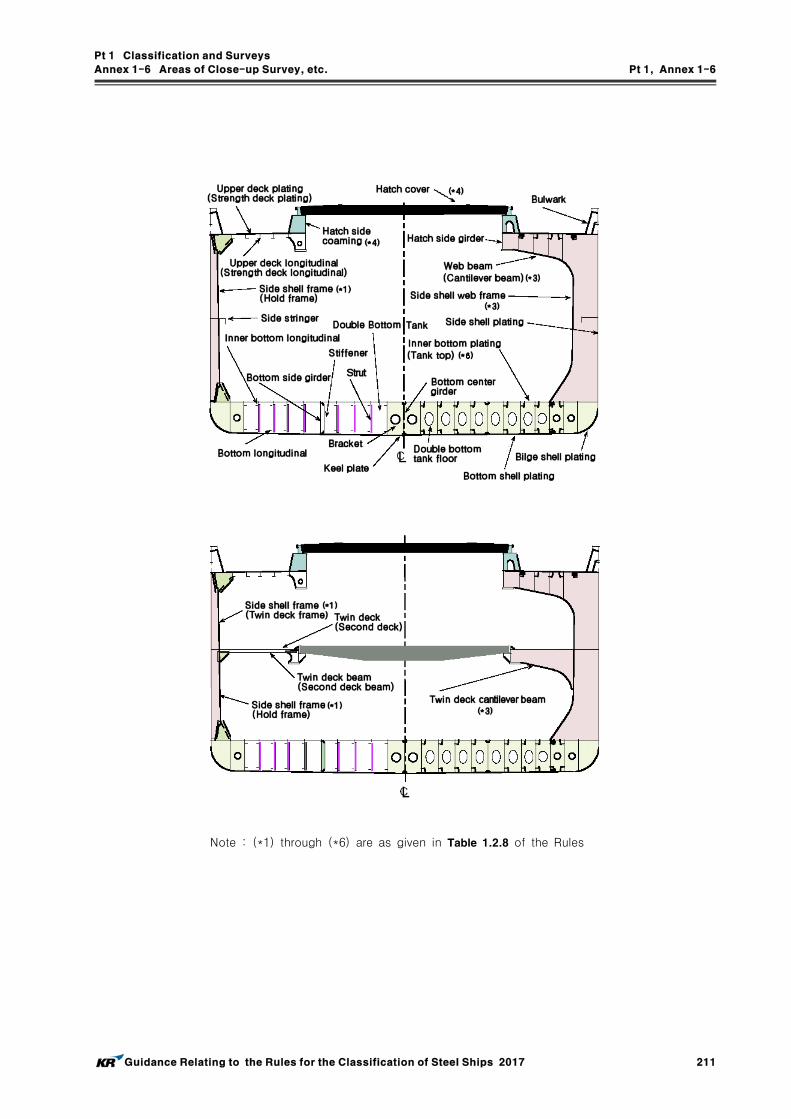
Pt 1 Classification and Surveys
Annex 1-6 Areas of Close-up Survey, etc. Pt 1, Annex 1-6
Guidance Relating to the Rules for the Classification of Steel Ships 2017 211
Note : (*1) through (*6) are as given in Table 1.2.8 of the Rules

Pt 1 Classification and Surveys
Annex 1-6 Areas of Close-up Survey, etc. Pt 1, Annex 1-6
212 Guidance Relating to the Rules for the Classification of Steel Ships 2017
(2) Areas of Close-up Survey for Bulk Carriers with ESP notation

Pt 1 Classification and Surveys
Annex 1-6 Areas of Close-up Survey, etc. Pt 1, Annex 1-6
Guidance Relating to the Rules for the Classification of Steel Ships 2017 213
(3) Areas of Close-up Survey for Oil Tankers with ESP notation
Note : (*1) through (*5) are as given in Table 1.3.4 of the Rules.

Pt 1 Classification and Surveys
Annex 1-6 Areas of Close-up Survey, etc. Pt 1, Annex 1-6
214 Guidance Relating to the Rules for the Classification of Steel Ships 2017
(4) Areas of Close-up Survey for Chemical Tankers with ESP notation

Pt 1 Classification and Surveys
Annex 1-6 Areas of Close-up Survey, etc. Pt 1, Annex 1-6
Guidance Relating to the Rules for the Classification of Steel Ships 2017 215
Note : (*1) through (*7) and (*A) through (*D) are as given in Table 1.3.7 of the Rules.

Pt 1 Classification and Surveys
Annex 1-6 Areas of Close-up Survey, etc. Pt 1, Annex 1-6
216 Guidance Relating to the Rules for the Classification of Steel Ships 2017
(5) Areas of Close-up Survey for Double Hull Oil Tankers with ESP notation
Note : (*1) through (*7) are as given in Table 1.3.10 of the Rules.

Pt 1 Classification and Surveys
Annex 1-6 Areas of Close-up Survey, etc. Pt 1, Annex 1-6
Guidance Relating to the Rules for the Classification of Steel Ships 2017 217
(6) Areas of Close-up Survey for Double Skin Bulk Carriers with ESP notation

Pt 1 Classification and Surveys
Annex 1-6 Areas of Close-up Survey, etc. Pt 1, Annex 1-6
218 Guidance Relating to the Rules for the Classification of Steel Ships 2017
Area(*2)
Ordinary transverse frame in double skin tank Ordinary longitudinal structure in double skin tank
Note : (*1) through (*5) are as given in Table 1.3.13 of the Rules

Pt 1 Classification and Surveys
Annex 1-6 Areas of Close-up Survey, etc. Pt 1, Annex 1-6
Guidance Relating to the Rules for the Classification of Steel Ships 2017 219
2. The typical midship sections of liquefied gas carriers specified in Table 1.2.10 of the Rules are indicated on the diagrams as follows.

Pt 1 Classification and Surveys
Annex 1-6 Areas of Close-up Survey, etc. Pt 1, Annex 1-6
220 Guidance Relating to the Rules for the Classification of Steel Ships 2017

Pt 1 Classification and Surveys
Annex 1-7 Continuous Machinery Survey Procedure(CMS) Pt 1, Annex 1-7
Guidance Relating to the Rules for the Classification of Steel Ships 2017 221
Annex 1-7 Continuous Machinery Survey Procedure(CMS)
1. Application of CMS
(1) Where the CMS system is intended to be applied, the Shipowner is to submit the "Application for CMS" including "CMS programme". The CMS system, in principle, is applied to machinery installation items of established type. However, the CMS system is not to be applied to non-propelled vessels unless special consideration is given by the Society. And the CMS pro-gramme is to be complied with the requirements as follows,(A) In principle, all items for CMS are to be included in the programme.(B) Consecutive survey intervals of each item are not to exceed 5 years. And all items are to
be examined in rotation.(C) Preferably, open-up schedules of machinery installations are to be planned to enable the at-
tending Surveyor to evaluate the condition of the whole system from the open-up results of any survey.
(D) The CMS programme above may be replaced with reference to the ship's maintenance programme. In cases where the ship's maintenance programme is modified in the process of implementation, the CMS programme on board may be partially or wholly amended.
(2) On the basis of the "CMS Programme" submitted by the Shipowner, the Society is to prepare the CMS status, thereafter. the CMS status is to be forwarded from the Head Office to the Shipowner after the completion of CMS. The CMS up-date status is to be kept on board for reference by the attending Surveyor.
(3) Items covered by the CMS system are, in principle, those shown in Table 1 of the Guidance.(4) In principle, it is preferable to conduct the open-up survey of essential auxiliaries(normally pro-
vided in duplicate or more) alternately at similar intervals. However, the surveys of diesel en-gines driving generators and bilge pumps is to be conducted, as far as practicable, simultaneous with the Special Survey or Intermediate Survey.
(5) When defects are found on a part during survey, a thorough examination may be required on other similar parts of machinery installations despite the "CMS programme" schedule.
2. Confirmatory Survey for CMS inspected by the Chief Engineer
(1) Qualification of Chief Engineer(A) The Chief Engineer is to have sailing experience of at least 3 years as a chief engineer or
be certified as a first-grade engineer by the relevant government and(B) The Chief Engineer has at least 1 year sailing experience on a ship installed with a similar
type of propulsion engine(internal combustion engine or steam turbine for main propulsion).(2) Where CMS permissible for the Chief Engineer's inspection are as given in Table 2 were over-
hauled(or open up) at sea and inspected by the Chief Engineer in routine maintenance works, the inspections may be accepted for the CMS. Whenever such an inspection was carried out by the Chief Engineer during the ship's stay in port(where the attendance of the Society's Surveyor is not easily available), the same process as above is applicable.
(3) The confirmatory survey by the Surveyor, in principle, is to be carried out by the timing of next periodical survey under the attending Surveyor as follows,(A) inspection of operational condition.(B) reviewing relevant details of the engine log book or maintenance record(e.g. acceptable com-
puter outputs) and hears the Chief Engineer's opinion. If review of the relevant log book and checking of oil and oil filter conditions indicate they are in good working condition, these may substitute for the open up survey of machinery installations listed below. Substitute items are to be recorded in the survey report.(a) Oil pumps(excluding cargo oil pumps) and oil heaters(b) Hydraulic pumps and motors for deck machinery(c) Oil tanks (having a capacity of 1 m or less)

Pt 1 Classification and Surveys
Annex 1-7 Continuous Machinery Survey Procedure(CMS) Pt 1, Annex 1-7
222 Guidance Relating to the Rules for the Classification of Steel Ships 2017
(C) Reporting submitted by the Chief Engineer including following contents(a) Signature and license number of the Chief Engineer(b) Inspection date and place(c) Inspection items and results.
(D) If necessary, the attending Surveyor may request the overhauling(or open-up) survey of rele-vant machinery according to the results of the Confirmatory Survey.
3. Unification of names and numbers for CMS items
(1) If there are items of CMS used for same purpose each ship, their names are to be unified in accordance with Table 3.
(2) For items of CMS used for same purpose are provided in duplicate or more on board, if their serial numbers are not assigned or uncertain, it is recommended for shipyard or shipowner to assign as belows, however, at existing ship the serial numbers of CMS are to be identified with ones attached to name plates or using name on board.(A) Numbering from Starboard to Port(B) Numbering from Fore to After.(C) Numbering from Upper to Lower.
(3) In case ships not applied to the CMS, (2) above may be applied to.

Pt 1 Classification and Surveys
Annex 1-7 Continuous Machinery Survey Procedure(CMS) Pt 1, Annex 1-7
Guidance Relating to the Rules for the Classification of Steel Ships 2017 223
Table 1 Items Covered by the CMS System
Items Details
1. Main diesel engines
(a) Cylinder covers, cylinder liners, pistons (including piston pins and piston rods), crossheads (including pins, bearings and guides), connecting rods, crank shafts and bearings, camshafts and their driving gears, turbo chargers, scavenge air pumps or blowers, air intercoolers, attached essential pumps (bilge, lubricating oil, fuel oil and cooling water)
2. Main steam turbines(a) Turbine rotors, blades, bearings, casings, nozzles, nozzle valves and maneuvering
valves
3. Power transmission systems and shafting systems
(a) Reduction gears, reversing gears, clutches and flexible couplings(b) Intermediate shafts, thrust shafts and their bearings
4. Auxiliary engines(a) Auxiliary engines driving generators (excluding emergency generators) or auxiliary
essential machinery are to be handled in accordance with the requirements applicable to main engines.
5. Auxiliary machinery
(a) Air compressors and blowers: main and auxiliary starting air compressors (excluding those for emergency use), air compressors for control system, forced draft fans for main boilers, gas compressors and gas blowers
(b) Pumps for essential uses:- Cooling fresh water pumps, cooling sea water pumps, fuel oil pumps and
lubricating oil pumps for main and auxiliary engines- Fuel oil pumps, feed water pumps and water circulating pumps for main boilers- Feed water pumps and water circulating pumps for auxiliary boilers- Thermal oil pumps- Condensing pumps for main engine- Sea water service pumps- Lubricating oil pumps for reduction gears- Lubricating oil pumps for stern tubes- Hydraulic oil pumps for controllable pitch propellers- Hydraulic oil pumps for steering gears- Hydraulic oil pumps for windlass and mooring winches- Bilge pumps (excluding those for oil separators), ballast pumps and fire pumps
(excluding emergency fire pumps)- Cargo oil pumps (including chemical pumps and liquefied gas pumps), stripping
pumps, spray pumps and tank cleaning pumps(c) Windlass and mooring winches(d) Cargo refrigerating installations (excluding those for provision storage): compressors,
pumps, evaporators and condensers(e) Fresh water generators for main boilers(f) Fuel oil heaters (excluding those for purifiers) and tank cleaning heaters(g) Condensers and feed water heaters(h) Coolers (excluding those for air compressors)(i) Inert gas systems(j) Air reservoirs (excluding those for emergency use) and other pressure vessels for
essential uses(k) Fuel oil tanks not form a part of the ship's structure(l) Other items considered to be applicable under the CMS by the Society
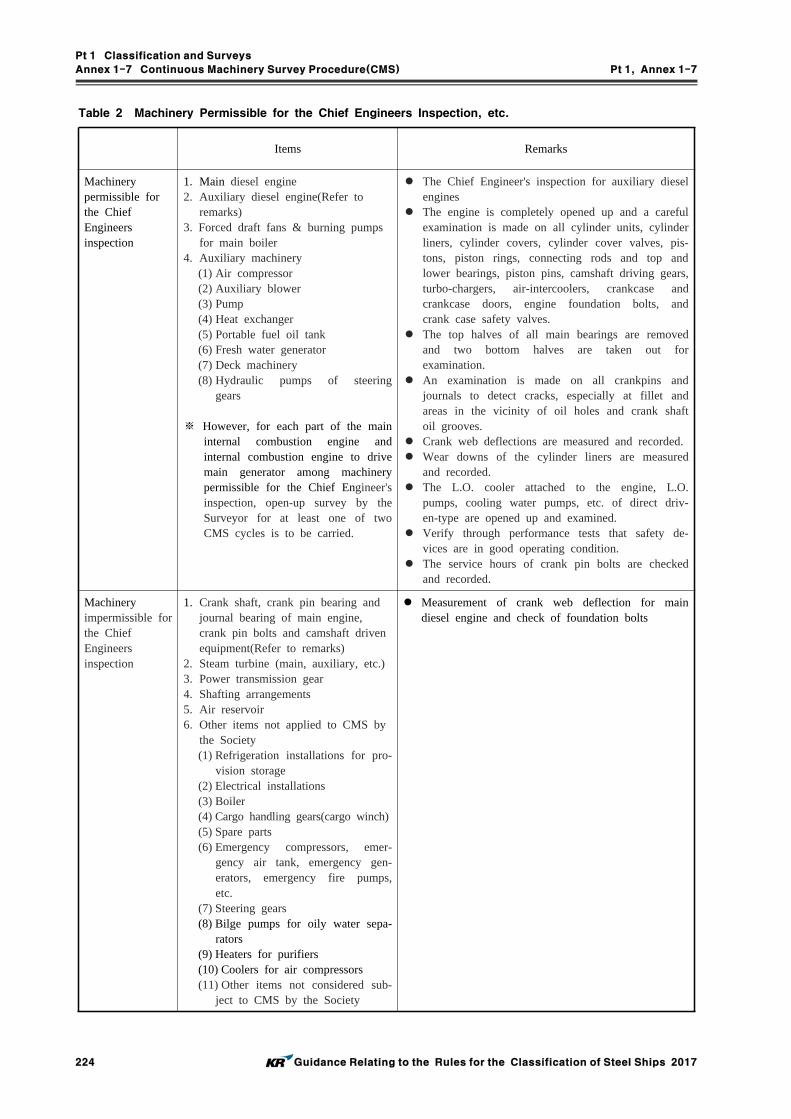
Pt 1 Classification and Surveys
Annex 1-7 Continuous Machinery Survey Procedure(CMS) Pt 1, Annex 1-7
224 Guidance Relating to the Rules for the Classification of Steel Ships 2017
Table 2 Machinery Permissible for the Chief Engineers Inspection, etc.
Items Remarks
Machinery permissible for the Chief Engineers inspection
1. Main diesel engine2. Auxiliary diesel engine(Refer to
remarks)3. Forced draft fans & burning pumps
for main boiler4. Auxiliary machinery
(1) Air compressor(2) Auxiliary blower(3) Pump(4) Heat exchanger(5) Portable fuel oil tank(6) Fresh water generator(7) Deck machinery(8) Hydraulic pumps of steering
gears
※ However, for each part of the main internal combustion engine and internal combustion engine to drive main generator among machinery permissible for the Chief Engineer's inspection, open-up survey by the Surveyor for at least one of two CMS cycles is to be carried.
The Chief Engineer's inspection for auxiliary diesel engines
The engine is completely opened up and a careful examination is made on all cylinder units, cylinder liners, cylinder covers, cylinder cover valves, pis-tons, piston rings, connecting rods and top and lower bearings, piston pins, camshaft driving gears, turbo-chargers, air-intercoolers, crankcase and crankcase doors, engine foundation bolts, and crank case safety valves.
The top halves of all main bearings are removed and two bottom halves are taken out for examination.
An examination is made on all crankpins and journals to detect cracks, especially at fillet and areas in the vicinity of oil holes and crank shaft oil grooves.
Crank web deflections are measured and recorded. Wear downs of the cylinder liners are measured
and recorded. The L.O. cooler attached to the engine, L.O.
pumps, cooling water pumps, etc. of direct driv-en-type are opened up and examined.
Verify through performance tests that safety de-vices are in good operating condition.
The service hours of crank pin bolts are checked and recorded.
Machinery impermissible for the Chief Engineers inspection
1. Crank shaft, crank pin bearing and journal bearing of main engine, crank pin bolts and camshaft driven equipment(Refer to remarks)
2. Steam turbine (main, auxiliary, etc.)3. Power transmission gear4. Shafting arrangements5. Air reservoir6. Other items not applied to CMS by
the Society(1) Refrigeration installations for pro-
vision storage(2) Electrical installations(3) Boiler(4) Cargo handling gears(cargo winch)(5) Spare parts(6) Emergency compressors, emer-
gency air tank, emergency gen-erators, emergency fire pumps, etc.
(7) Steering gears(8) Bilge pumps for oily water sepa-
rators(9) Heaters for purifiers(10) Coolers for air compressors(11) Other items not considered sub-
ject to CMS by the Society
Measurement of crank web deflection for main diesel engine and check of foundation bolts

Pt 1 Classification and Surveys
Annex 1-7 Continuous Machinery Survey Procedure(CMS) Pt 1, Annex 1-7
Guidance Relating to the Rules for the Classification of Steel Ships 2017 225
Table 3 Table for Unified Name of Machinery
* The following unified expressions will be used in the Society's CMS system for the machinery which has the same purpose but are variously named from ship to ship.
SystemUnified name of machinery to be used in
CMS systemVarious names of machinery actually used in
ships
Cooling SeaWater System
Main Cooling S.W. Pump- Main Cooling S.W. Pump- Main Condenser Cooling S.W. Pump
Reserve Cooling S.W. Pump- Reserve Cooling S.W. Pump- Stand-by Cooling S.W. Pump
A/E Cooling S.W. Pump- A/E Cooling S.W. Pump- Aux. Machinery Cooling S.W. Pump- Aux. G/T Cooling S.W. Pump
Aux. Condenser Cooling S.W. Pump
- Aux Condenser Cooling S.W. Pump- Dumping Condenser Cooling S.W. Pump- Vacuum Condenser Cooling S.W. Pump- Atmospheric Condenser Cooling S.W. Pump- Drain Cooler Cooling S.W. Pump
M/E F.W. Generator(Cooling) S.W Pump
S.W. Circulating Pump
I.G.G Cooling Water Pump
Sea WaterService System
S.W. Service Pump
Cooling FreshWater System
M/E Cooling F.W. Pump- M/E Cooling F.W. Pump- Main Cooling F.W. Pump
M/E Reserve Cooling F.W. Pump- Reserve Cooling F.W. Pump- Cooling F.W. Service Pump
Aux. Cooling F.W. Pump- Aux Cooling F.W. Pump- Air Intercooler Cooling F.W. Pump- Turbo Charger Cooling F.W. Pump
M/E Jacket Cooling F.W. Pump
M/E Piston Cooling F.W. Pump
Central Cooling F.W. Pump
A/E Cooling F.W. Pump- A/E Cooling F.W. Pump- Harbour Cooling F.W. Pump
Fuel Oil System
M/E F.O.V. Cooling Pump- M/E F.O.V. Cooling Pump- M/E F.O.V. Cooling F.W (or Oil) Pump
A/E F.O.V. Cooling Pump
M/E F.O. Supply/Booster Pump
M/E F.O. Supply pump
- M/E F.O. Supply Pump- Main H.F.O. Supply pump- Main I.F.O. Supply pump- Main M.D.O. Supply pump- Reserve F.O. Supply pump- F.O. Feed pump- Res. F.O. Supply & F.O. Valve Cooling pump- F.O. Supply & F.O. Transfer pump- Stand-by F.O. Supply Pump
M/E F.O. Booster Pump
M/E F.O. Service Pump- M/E F.O. Service Pump- M/E C Oil Service Pump
A/E F.O. Supply Pump
A/E F.O. Service Pump- A/E F.O. Service Pump- A/E C Oil Service Pump

Pt 1 Classification and Surveys
Annex 1-7 Continuous Machinery Survey Procedure(CMS) Pt 1, Annex 1-7
226 Guidance Relating to the Rules for the Classification of Steel Ships 2017
Table 3 Table for Unified Name of Machinery (continued)
SystemUnified name of machinery to be used in
CMS systemVarious names of machinery actually used in
ships
Fuel Oil System (Cont’d)
D.O. Service Pump- D.O. Service Pump- A Oil Service Pump
F.O. Transfer Pump
- F.O. Transfer Pump- C Oil Transfer Pump- H.F.O. Transfer Pump- I.F.O. Transfer Pump- F.O. Shift Pump- F.O. Transfer & Shift Pump- H.F.O. & M.D.O. Transfer Pump
D.O. Transfer Pump- D.O. Transfer Pump- A Oil Transfer Pump- M.D.O. Transfer Pump
M/E F.O. Circulating Pump- F.O. Circulating Pump- F.O. Recycle Pump
Main Boiler F.O. Service Pump
- Boiler F.O. Service Pump- Boiler F.O. Feed Pump- Boiler F.O. Supply Pump- Boiler F.O. Transfer Pump
Main Boiler D.O. Service Pump
- Boiler D.O. Service Pump- Boiler D.O. Feed Pump- Boiler D.O. Supply Pump- Boiler D.O. Transfer Pump
Main Boiler Burning Pump- Boiler Burning Pump- Boiler Pilot Burner F.O. Pump
Lub. Oil System
M/E L.O. Pump
A/E L.O. Pump- A/E L.O. Pump- A/E Reserve L.O. Pump- A/E L.O. Service Pump
M/E Reserve L.O. Pump- Reserve L.O. Pump- Aux. L.O. Pump- Stand-by L.O. Pump
M/E L.O. Service Pump- L.O. Service Pump- Rocker Arm L.O. Pump- Priming L.O. Pump
M/E Crosshead L.O. Pump
M/E Camshaft L.O. Pump
M/E Piston rod Stuffing Box L.O. Pump
M/E Turbo-charger L.O. Pump
Reduction Gear L.O. Pump
L.O. Transfer Pump- L.O. Transfer Pump- L.O. Shift Pump
Stern Tube L.O. Pump- Stern Tube L.O. Pump- Forward Seal Cooling L.O. Pump- After Seal Cooling L.O. Pump
C.P.P. Hyd. Oil Pump
Bilge System Bilge Pump
- Bilge Pump- Aux. Bilge Pump- Bilge & Sanitary Pump- Bilge Transfer Pump

Pt 1 Classification and Surveys
Annex 1-7 Continuous Machinery Survey Procedure(CMS) Pt 1, Annex 1-7
Guidance Relating to the Rules for the Classification of Steel Ships 2017 227
Table 3 Table for Unified Name of Machinery (continued)
SystemUnified name of machinery to be used
in CMS systemVarious names of machinery actually used in ships
Bilge System(Cont’d)
Fire & Bilge Pump
- Bilge & Fire Pump- Bilge, Fire & G.S. Pump- Bilge, Fire & Cooling S.W. Pump- Fire, G.S. & S.W. Service Pump- G.S. (& Fire) & Pump
Bilge & Ballast (& Fire) Pump- Bilge & Ballast Pump- Bilge, Ballast & Fire Pump- Bilge, Ballast (& Fire) & Cooling S.W. Pump
Ballast System
Ballast Pump
- Ballast Pump- Ballast & Cooling S.W. Pump- Ballast & G.S. Pump- Ballast & S.W. Service Pump
Stripping Pump
Heeling Pump- Heeling Pump- Heeling & Trimming Pump
Feed WaterSystem
Main Boiler Feed Water Pump
- Main Boiler Feed Water Pump- Exh. Gas Boiler Feed Water Pump- Exh. Gas Economizer Feed Water Pump- L.P. Steam Generator Feed Water Pump
Aux. Boiler Feed Water Circulating Pump
- Aux. Boiler Feed Water Pump- Aux. Exh. Gas Economizer Feed Water Pump- Aux. L.P. Steam Generator Feed Water Pump
Main Boiler Water Circulating Pump
- Main Boiler Water Circulating Pump- Exh. Gas Boiler Water Circulating Pump- Exh. Gas Economizer Water Circulating Pump- Hot Water Circulating Pump
Aux. Boiler Water Circulating Pump
- Aux. Boiler Water Circulating Pump- Aux. Exh. Gas Boiler Water Circulating Pump- Aux. Exh. Gas Economizer Water Circulating Pump- Hot Water Circulating Pump
Main Condensate Pump
Condensate Pump for Aux. Turbine
Reserve Condensate Pump- Reserve Condensate Pump- Aux. Condensate Pump- Condensate & Drain Transfer Pump
Dump drain Transfer Pump
Condenser Circulating Pump
- Condenser Circulating Pump- Vacuum Condenser Circulating Pump- Atmospheric Condenser Circulating Pump- Drain Cooler Circulating Pump- Aux. Condenser Circulating Pump
Fresh WaterSystem
F.W. Generator for Main Boiler
Air System
Main Air Compressor- Main Air Compressor- Main Engine Starting Air Compressor
Reserve Air Compressor
- Aux. Air Compressor- Working Air Compressor- Topping up Air Compressor- Instrument Air Compressor- Reserve Air Compressor
Control Air Compressor

Pt 1 Classification and Surveys
Annex 1-7 Continuous Machinery Survey Procedure(CMS) Pt 1, Annex 1-7
228 Guidance Relating to the Rules for the Classification of Steel Ships 2017
Table 3 Table for Unified Name of Machinery (continued)
SystemUnified name of machinery to be used in
CMS systemVarious names of machinery actually used in ships
Fresh Water Cooler
M/E Main Cooling F.W. Cooler- M/E Main Cooling F.W. Cooler- Central F.W. Cooler
M/E Jacket Cooling F.W. Cooler
M/E Piston Cooling F.W. Cooler
A/E F.O.V. Cooling F.W. Cooler - F.O.V. F.W. Cooler- Fuel Valve & Turbo Charger F.W. Cooler- F.O.V. & Exh. V. Cooling F.W. CoolerA/E F.O.V. Cooling F.W. Cooler
A/E Cooling F.W. Cooler
A/E Turbo-charger Cooling F.W. Cooler
Exh. Valve Cooling F.W. Cooler
F.W. Cooler for Air Compressor
Oil Cooler
M/E F.O.V. Cooling Oil Cooler
A/E F.O.V. Cooling Oil Cooler
M/E L.O. Cooler- M/E L.O. Cooler- Main Turbine L.O. Cooler
A/E L.O. Cooler- A/E L.O. Cooler- Aux. Turbine L.O. Cooler
M/E Turbo-charger L.O. Cooler
A/E Turbo-charger L.O. Cooler
Stern Tube L.O. Cooler
Reduction Gear L.O. Cooler
M/E Camshaft L.O. Cooler
C.P.P. Hyd. Oil Cooler
Feed Water Cooler
Aux. Turbine Condenser- Aux. Turbine Condenser- G/T Condenser
Atmospheric Condenser- Aux. Atmospheric Condenser- Aux. Condenser- Aux. Condenser & Drain Cooler
Vacuum Condenser - Vacuum Condenser
Dump Condenser - Dump Condenser
Drain Cooler- Drain Cooler- Oil Heating Drain Cooler
Main Condenser
Oil Heater
M/E F.O. Heater
A/E F.O. Heater
Main Boiler F.O. Heater - Boiler F.O. Heater (Steam)- Boiler F.O. Heater (Electric)Aux. Boiler F.O. Heater
Thermal Oil Heater
Thermal Oil Heater
Feed Water Heater
Main Boiler Feed Water Heater
Aux. Boiler Feed Water Heater- Aux. Feed Water Heater- Aux. Boiler Feed Water Heater
Deaerator - Deaerator
Deaerating Feed Water Heater - Deaerating Feed Water Heater
L.P. Feed Water Heater
1st Feed Water Heater
2nd Feed Water Heater
3rd Feed Water Heater
4th Feed Water Heater

Pt 1 Classification and Surveys
Annex 1-7 Continuous Machinery Survey Procedure(CMS) Pt 1, Annex 1-7
Guidance Relating to the Rules for the Classification of Steel Ships 2017 229
Table 3 Table for Unified Name of Machinery (continued)
SystemUnified name of machinery to be used in
CMS systemVarious names of machinery actually used in
ships
Fresh Water Heater
Hot Water Heater- Hot Water Heater- Calorifier
Main Engine F.W. Heater
Other Heat Exchanger
F.W. Generator for Main Boiler
Refrigerator Condenser
Air Reservoir
Main Air Reservoir- Main Air Reservoir- Main Engine Starting Air Reservoir
A/E Air Reservoir
- Aux. Air Reservoir- Working Air Reservoir- Aux. Engine Starting Air Reservoir- Cargo Pump Engine Starting Air Reservoir- Em’cy Air Reservoir
Service Air Reservoir
Control Air Reservoir
F.O. Tank
M/E F.O. Settling Tank
- M/E F.O. Settling Tank- M/E H.F.O. Settling Tank- M/E I.F.O. Settling Tank- M/E M.D.O. Settling Tank
M/E F.O. Service Tank
- M/E F.O. Service Tank- M/E H.F.O. Service Tank- M/E I.F.O. Service Tank- M/E M.D.O. Service Tank
A/E F.O. Settling Tank- A/E F.O. Settling Tank- A/E A Oil Settling Tank
A/E F.O. Service Tank- A/E F.O. Service Tank- A/E A Oil Service Tank- A/E F.O. Tank
Boiler F.O. Settling Tank- Boiler F.O. Settling Tank- Boiler H.F.O. Settling Tank- Boiler M.D.O. Settling Tank
Boiler F.O. Service Tank- Boiler F.O. Service Tank- Boiler H.F.O. Service Tank- Boiler M.D.O. Service Tank
D.O. Settling Tank
D.O. Service Tank
Cargo System
Cargo Pump
- Cargo (Oil) Pump- Cargo Pump (Motor)- Aux. Cargo Pump- Cargo & Ballast Pump
Stripping Pump
Spray Pump
Pump in Pump Room
Ballast Pump in Pump Room
Clean Ballast Pump in Pump Room
Ballast Pump in FWD. Pump Room(or F’CLE)
- Ballast Pump in FWD. Pump Room- Ballast Pump in F’CLE
Bilge Pump
S.W. Service Pump

Pt 1 Classification and Surveys
Annex 1-7 Continuous Machinery Survey Procedure(CMS) Pt 1, Annex 1-7
230 Guidance Relating to the Rules for the Classification of Steel Ships 2017
Table 3 Table for Unified Name of Machinery (continued)
SystemUnified name of machinery to be used in CMS system
Various names of machinery actually used in ships
Tank CleaningSystem
Tank Cleaning Pump
- Tank Cleaning Pump- Butterworth Pump- Tank Cleaning & Fire Pump- Butterworth & Tank Cleaning Pump- Tank Cleaning & Bilge, Fire, (G.S.) Pump- Butterworth & Bilge, Fire, (G.S.) Pump
Tank Cleaning Heater- Tank Cleaning Heater- Butterworth heater
Tank Cleaning Drain Cooler- Tank Cleaning Drain Cooler- Butterworth Drain Cooler
Other Machinery in Pump Room
Ventilation Fan
Deck Machinery
Hyd. Pump for Steering Gear
Windlass
Mooring Winch- Mooring Winch- Auto Tension Winch
Hyd. Pump for Deck Machinery
Capstan
CargoRefrigeratingMachinery
Compressor
Condenser Cooling Pump- Condenser Cooling Pump- Ref. Cooling S.W. (or F.W.) Pump- Ref. & Aux. Cooling S.W. (or F.W.) Pump
Brine Pump
Refrigerant Pump
Condenser
Evaporator
Evaporator Cooling S.W. Pump
Machinery forGas Carrier
Gas Compressor
High Duty Compressor
Low Duty Compressor
Vacuum Pump
Main Vaporizer
Forced Vaporizer
Boil-off/Warm-up Heater
Vent Gas Heater
N2 Generator Unit
N2 Buffer Tank
Inert Gas Generator
Cargo Heating Drain Cooler
Glycol Water Steam Heater
Glycol Water Electric Heater
Glycol Water Circulating pump

Pt 1 Classification and Surveys
Annex 1-8 Planned Maintenance System Procedure(PMS) Pt 1, Annex 1-8
Guidance Relating to the Rules for the Classification of Steel Ships 2017 231
Annex 1-8 Planned Maintenance System Procedure(PMS)
1. General
(1) At the request of Owner, PMS is to be approved by the Society in accordance with Fig 1 and Information and Documents given in Table 1 including the following items are to be submitted.(A) organization chart identifying areas of responsibility(B) documentation filling procedures(C) listing of equipment to be considered by the Society in PMS(D) machinery identification procedure(E) preventing maintenance sheets for each machine to be considered(F) listing and specifications of condition monitoring equipment(G) baseline data for equipment with condition monitoring,(H) listing and schedule of preventive maintenance procedure.
(2) In addition to the above documentation the following information shall be available on board:(A) the above (1) in an up-to-date fashion(B) maintenance inspection(manufacturer's and shipyard's)(C) condition monitoring data including all data since last opening of the machine and the origi-
nal base line data(D) reference documentation (trend investigation procedure etc.)(E) records of maintenance including repairs and renewals carried out.
(3) An annual report covering the year's service, including the following information, shall be re-viewed by the Society:(A) clauses (1) (C), (D), (E) and (G) as well as changes to other clause in the above (1)(B) clause (2) (C)(C) full trend analysis(including spectrum analysis for vibrations) of machinery displaying operat-
ing parameters exceeding acceptable tolerances.(4) In general, the intervals for PMS shall not exceed those specified for CMS. However, for com-
ponents where the maintenance is based on running hours longer intervals may be accepted as long as the intervals are based on the manufacturer's recommendations. However, if an approved condition monitoring system is in effect, the machinery survey intervals based on CMS cycle period may be extended
(5) The PMS shall be programmed and maintained by a computerized system. However, this may not be applied to the current already approved schemes. Computerized systems shall include back-up devices, such as disks/tapes, CDs, which are to be updated at regular intervals.
2. Chief Engineer's responsibility of PMS.
(1) Where a chief engineer is entitled to be complied with the following requirements, the Society is to issue the Chief Engineer Qualification Certificate.(A) First-grade licence issued in the relevant nation is to be provided.(B) To be recommended by the shipowner(or ship management company) and approved by the
Society.(2) The chief engineer shall be the responsible person on board in charge of the PMS.(3) Documentation on overhauls of items covered by the PMS shall be reported and signed by the
chief engineer.(4) Access to computerized systems for updating of the maintenance documentation and maintenance
program shall only be permitted by the chief engineer or other authorized person.(5) PMS items to be maintained by Chief Engineer is to be complied with Table 2 and to be re-
tained on board the overhauled(or opened up) records. However, PMS items not permitted by Chief Engineer's records in Table 2 are to be surveyed under the attending surveyor as far as practicable at Annual Survey.

Pt 1 Classification and Surveys
Annex 1-8 Planned Maintenance System Procedure(PMS) Pt 1, Annex 1-8
232 Guidance Relating to the Rules for the Classification of Steel Ships 2017
3. Condition monitoring system(CM)
(1) When it is ascertained that the ship under the approved PMS has been installed with condition monitoring system, the inspection for the following items has been confirmed by the Surveyor at the periodical survey, the overhaul(or open-up) intervals on the PMS may be extended. However, the (B) below are to be submitted to the Surveyor.(A) Conditions and functions of condition monitoring equipment.(B) Measurements and analysis results obtained from condition monitoring equipment for each
machine to be considered.(Refer to Table 3)(C) Operating condition of each equipment
(2) Where the measurements and analysis results obtained from the previous paragraph are to be re-viewed and they are found in unsatisfactory by the Surveyor, overhauling(or opening up) exami-nation may be requested.
(3) The Implementation Survey after installation of the condition monitoring system is to be carried out.
Fig 1 Flow chart for approval procedures

Pt 1 Classification and Surveys
Annex 1-8 Planned Maintenance System Procedure(PMS) Pt 1, Annex 1-8
Guidance Relating to the Rules for the Classification of Steel Ships 2017 233
Table 1 Information and Documents to be submitted
Name and content Remarks
(1) Machinery inventory content: Listing of machinery subjected to maintenance, and index or
code for each machinery.
Unify classification nomenclature for machi-nery to use the same names as far as possible.
machinery index or code and CMS code. Identify and mark items not permitted by
the chief engineer.
(2) Maintenance schedule:(A) It is to be stated for PMS of each item of machinery
as follows:- Identification of overhaul survey, kind of inspection
and test and content of measurement record- Intervals of overhaul survey, inspection and measure-
ment(B) It is to be stated for CM as follows:
- Layout of CM, maker, model and specification of CM equipment
- Measuring points, names of measuring instruments and measuring parameters for each machinery
- Intervals of measurement for each machinery- Acceptable limits for monitored condition for each
machinery- Examples of input and output data
To be satisfied the Rules requirements for overhaul survey, inspection, measurement, etc. of all machinery.
To be overhauled with period not to exceed 5 year
To be confirmed that quantity of machinery to be surveyed every year is not less than about 20 % of machinery covered by PMS.
To be reviewed CM layout and feasibility of measuring parameters.
To be sure that output format is easily rec-ognizable by the chief engineer.
To be reviewed the feasibility of acceptable limit.
(3) Reporting system:(A) To be stated in the program as follows:
- Records of maintenance and repairs- Spare parts
(B) A regular reporting system between the ship and the supporting land department of the ship company is to be stated.
Ease in confirming that all reporting and re-cording procedures are carried out exactly.
(4) Documents for qualification requirements of the chief en-gineer:(A) Copy of chief engineer's licence(B) Chief engineer's resume
To be satisfied with the requirements of chief engineer's qualification.
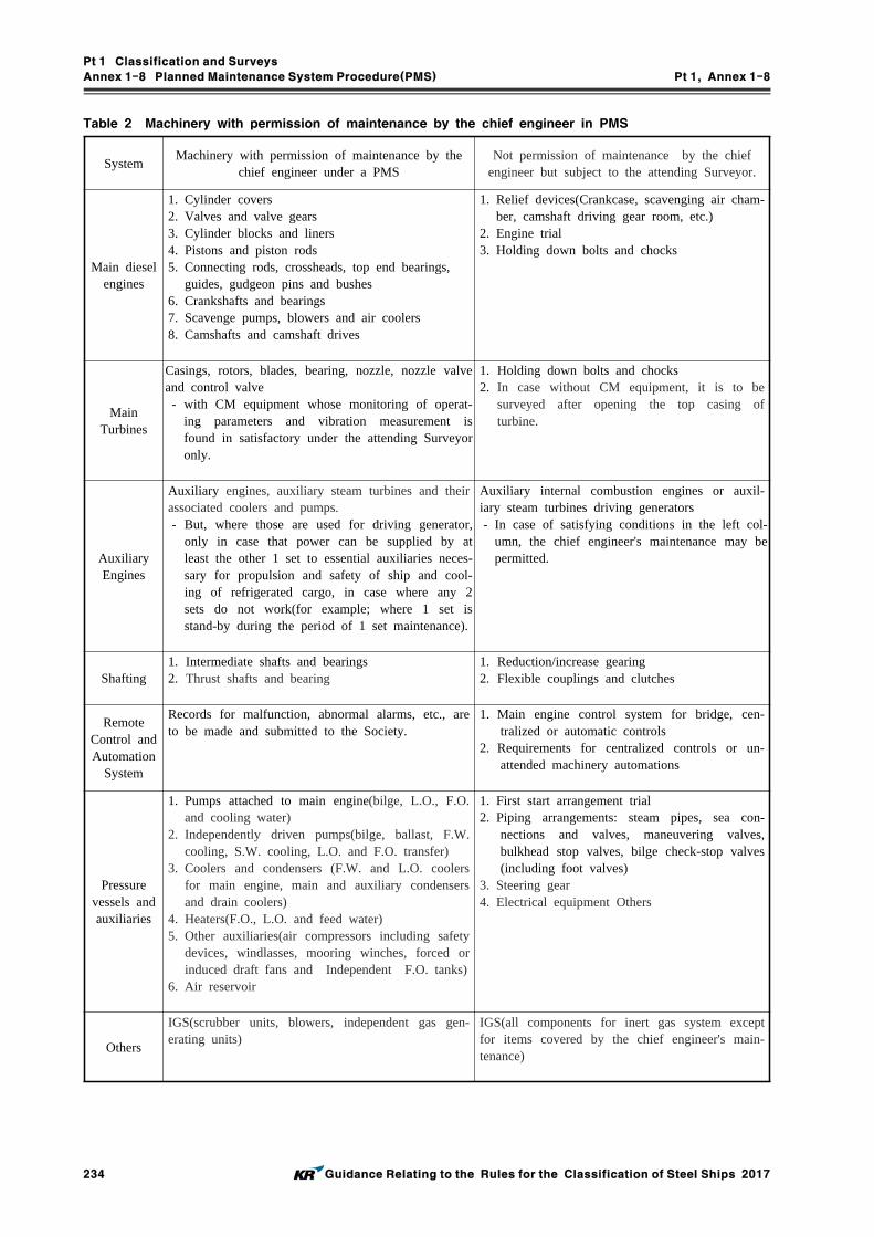
Pt 1 Classification and Surveys
Annex 1-8 Planned Maintenance System Procedure(PMS) Pt 1, Annex 1-8
234 Guidance Relating to the Rules for the Classification of Steel Ships 2017
Table 2 Machinery with permission of maintenance by the chief engineer in PMS
SystemMachinery with permission of maintenance by the
chief engineer under a PMSNot permission of maintenance by the chief
engineer but subject to the attending Surveyor.
Main diesel engines
1. Cylinder covers2. Valves and valve gears3. Cylinder blocks and liners4. Pistons and piston rods5. Connecting rods, crossheads, top end bearings,
guides, gudgeon pins and bushes6. Crankshafts and bearings7. Scavenge pumps, blowers and air coolers8. Camshafts and camshaft drives
1. Relief devices(Crankcase, scavenging air cham-ber, camshaft driving gear room, etc.)
2. Engine trial3. Holding down bolts and chocks
Main Turbines
Casings, rotors, blades, bearing, nozzle, nozzle valve and control valve - with CM equipment whose monitoring of operat-
ing parameters and vibration measurement is found in satisfactory under the attending Surveyor only.
1. Holding down bolts and chocks2. In case without CM equipment, it is to be
surveyed after opening the top casing of turbine.
Auxiliary Engines
Auxiliary engines, auxiliary steam turbines and their associated coolers and pumps. - But, where those are used for driving generator,
only in case that power can be supplied by at least the other 1 set to essential auxiliaries neces-sary for propulsion and safety of ship and cool-ing of refrigerated cargo, in case where any 2 sets do not work(for example; where 1 set is stand-by during the period of 1 set maintenance).
Auxiliary internal combustion engines or auxil-iary steam turbines driving generators - In case of satisfying conditions in the left col-
umn, the chief engineer's maintenance may be permitted.
Shafting1. Intermediate shafts and bearings2. Thrust shafts and bearing
1. Reduction/increase gearing2. Flexible couplings and clutches
Remote Control and Automation
System
Records for malfunction, abnormal alarms, etc., are to be made and submitted to the Society.
1. Main engine control system for bridge, cen-tralized or automatic controls
2. Requirements for centralized controls or un-attended machinery automations
Pressure vessels and auxiliaries
1. Pumps attached to main engine(bilge, L.O., F.O. and cooling water)
2. Independently driven pumps(bilge, ballast, F.W. cooling, S.W. cooling, L.O. and F.O. transfer)
3. Coolers and condensers (F.W. and L.O. coolers for main engine, main and auxiliary condensers and drain coolers)
4. Heaters(F.O., L.O. and feed water)5. Other auxiliaries(air compressors including safety
devices, windlasses, mooring winches, forced or induced draft fans and Independent F.O. tanks)
6. Air reservoir
1. First start arrangement trial2. Piping arrangements: steam pipes, sea con-
nections and valves, maneuvering valves, bulkhead stop valves, bilge check-stop valves (including foot valves)
3. Steering gear4. Electrical equipment Others
Others
IGS(scrubber units, blowers, independent gas gen-erating units)
IGS(all components for inert gas system except for items covered by the chief engineer's main-tenance)

Pt 1 Classification and Surveys
Annex 1-8 Planned Maintenance System Procedure(PMS) Pt 1, Annex 1-8
Guidance Relating to the Rules for the Classification of Steel Ships 2017 235
Table 3 Machinery Operating Parameter for Condition monitoring System
Items Operating Parameter
Main Diesel Engine
1. Shaft horse power2. Engine and Shaft RPM3. Cylinder pressure-time curves4. Oil fuel injection pressure-time curves5. Oil fuel temperature or viscosity6. Charge air pressure7. Exhaust gas temperatures8. Engine cooling systems, temperatures and pressures9. Engine lubricating oil system, temperatures and pressures10. Turbo-charger RPM and vibration11. Lubricating oil analysis data12. Crankshaft deflections13. Main bearing temperatures
Main Steam Turbine
1. Turbine rotor vibration2. Turbine rotor axial displacement3. Shaft horsepower4. Shaft and turbine rotor FPM5. Performance data;
(1) Steam conditions at inlet and outlet of each turbine(2) Boiler performance data(3) Condenser vacuum(4) Sea temperatures(5) Steam conditions of other major steam consuming auxiliaries
Auxiliary Steam Turbine Same as main steam turbine
Auxiliary Diesel Engine
1. Exhaust gas temperatures2. Engine cooling systems temperatures and pressures3. Engine L.O. system; temperatures and pressures4. Turbo-charger RPM and vibration5. Lub. oil analysis data6. Crankshaft deflections
Auxiliaries
1. Cooler efficiency, inlet and outlet temperatures2. Heater temperatures3. Pumps and fans; vibration and performance4. Differential pressure across filters

Pt 1 Classification and Surveys
Annex 1-9 Guidance for Survey of Waterjet Propulsion Systems and Azimuth or Rotatable Thruster Pt 1, Annex 1-9
236 Guidance Relating to the Rules for the Classification of Steel Ships 2017
Annex 1-9 Guidance for Survey of Waterjet Propulsion Systems and Azimuth or Rotatable Thruster
1. The surveys for waterjet propulsion systems and azimuth or rotatable thruster are to comply with the following requirements.(1) Waterjet propulsion systems
(A) Annual SurveysAt each Annual Survey, the following surveys and inspections are to be carried out.(a) General inspection of the propulsion system(b) Verification test of steering performance(c) Operation test of the reverser(d) General inspection of impeller(e) Function test of alarm and safety devices, and indication devices for deflector positions,
reverser positions and impeller speed, and running indicators of electric motors for hy-draulic power systems (2017)
(f) Operation test of controls for steering and reversing systems, including tests on change-overs of control systems between navigation bridges and auxiliary steering sta-tions, and change-overs between manual steering and automatic steering. (2017)
(g) Tests for supply of the alternative souce of power specified in Pt 5, Annex 5-1, 1 (4) (F) of the Guidance. (2017)
(h) External examination of oil piping and sea water piping (2017)(B) Intermediate Surveys
At each Intermediate Survey, all the requirements of Annual Survey are to be complied with. (2017)
(C) Special Surveys (2017)(a) At each Special Survey, all the requirements of Intermediate Survey are to be complied
with.(b) open-up inspections for major part of the hydraulic pump are to be carried.(c) Holding parts and pins of deflectors or reversers are to be opened up and it is to be
confirmed that they are in good working order.(D) Docking Surveys (2017)
At each Docking Survey, the following surveys and inspections are to be carried out.(a) The wearing condition of the bearing is to be verified with means deemed appropriate
by the Society.(b) General inspection of the forward sealing device. Where considered necessary by the
Surveyor, opening up examination may be requested. (2017)(c) Deflector and reverser are to be inspected. (2017)(d) Water intake ducts are to be confirmed to be in good working order. (2017)(e) General inspection of water jet pump (2017)(f) Survey required in Ch 2, 603. 6 of the Rules. (2017)
(E) Main Shaft Surveys (2017)(a) The survey interval is 5 years from the completion date of the previous survey. (b) After drawing out the main shaft, the condition of the main shaft are to be examined.
Where "drawing out" means preparing to be able to sufficiently examine the condition of the main shaft.
(c) General inspection of coupling bolts(d) General inspection of the major parts of the forward and after main shaft bearings(e) General inspection of the major parts of the forward main shaft sealing assembly(f) Open-up inspection for thrust bearing(g) Inspection of the contact faces of the impeller boss and main shaft(when installed with
key and spline)(2) Azimuth or rotatable thruster (2017)
(A) Annual Surveys At each Annual Survey, the following surveys and inspections are to be carried out.(a) General inspection of the thruster(b) Performance tests of azimuth steering gears(c) Function test of alarm and safety devices as well as indication devices for azimuth an-
gles, propeller speeds and direction of rotation and pitch positions, and running in-dicators of electric motors for azimuth steering gears.

Pt 1 Classification and Surveys
Annex 1-9 Guidance for Survey of Waterjet Propulsion Systems and Azimuth or Rotatable Thruster Pt 1, Annex 1-9
Guidance Relating to the Rules for the Classification of Steel Ships 2017 237
(d) Operation tests of controls for steering, including the follings: (i) tests on change-overs of control systems between navigation bridges and azimuth
thruster compartments,(ii) tests on change-overs between manual steering and automatic steering, if provided.
(e) Tests for supply of the alternative souce of power specified in Pt 5, Annex 5-1, 2 (4) (F) of the Guidance.
(f) For thrusters which incorporate electric motors in propeller pods, function tests of the followings:(i) Means to detect ingress of sea water into propeller pods(ii) Where cooling fans are provided for propulsion motors, cooling fans, control means
for stopping such fans and closing any inlets and outlets of air for such fans(B) Intermediate Surveys
At each Intermediate Survey, all the requirements of Annual Survey are to be complied with.
(C) Special Surveys(a) At each Special Survey, all the requirements of Intermediate Survey are to be complied
with.(b) Inspections for supporting parts of azimuth steering gears are to be carried out.
(D) Docking Surveys(a) At each Docking Survey, survey required in Ch 2, 603. 6 of the Rules are to be car-
ried out.(E) Propeller Shaft Surveys and Gear unit open-up Surveys
Inspections and surveys specified in the following (a) through (e) are to be carried out.(a) The survey interval is 5 years from the completion date of the previous survey.(b) Open-up inspection for propeller shaft sealing device(c) Examination by surface crack-detection method specified in Ch 2, 702. 1 (1) (B) and
(C) of the Rules(d) General examination for each bearing(e) Open-up inspection for gear unit. At the first Survey after delivery, on the basis of a
satisfactory lubrication oil sample analysis, service record, and external examination, open-up inspection may be omitted.
2. For the items which are not specified in Par 1 above, the relevant provisions for propeller shaft, propeller, steering gear and stern tube sealing device specified in Ch 2, Sec 2 through Sec 7 of the Rules, are to be applied with the necessary modifications.

Pt 1 Classification and Surveys
Annex 1-10 Loading Instrument on Stability Pt 1, Annex 1-10
238 Guidance Relating to the Rules for the Classification of Steel Ships 2017
Annex 1-10 Loading Instrument on Stability
1. Application
(1) This requirement applies to ships having a length exceeding 24 metres when a loading instru-ment with a stability computation capability(hereinafter called "loading instrument on stability") is installed on a new ship or newly installed on an existing ship in accordance with the re-quirement in Ch 1, 307. of the Rules.
(2) For the purpose of this requirements, "new ship" means a ship for which the application for Classification Survey during Construction is made on or after 1 January 1997 and "existing ship" means a ship for the application for Classification Survey during Construction before 1 January 1997.
2. Approval procedure (2017)
(1) The procedure for approval of a loading instrument on stability is as illustrated in Fig 1.
* The approval of the software should be carried out in accordance with "Guidance for Approval of Manufacturing Process and Type Approval, Etc."
Submit User's Manual and Test
conditions
Review of User's Manual and Approval of
Test conditions
On-board Installation Test
Issue Certificate of Loading Instrument
Design Approval of the Software, if requested
Approval Data or Calculation output by
the Society
Fig 1 Procedure for the approval of loading instrument on stability for a specific ship.
(A) User's manual and 3 copies of test conditions are to be submitted to Head Office. The load-ing instrument on stability of test conditions may be approved provisionally if the stability information booklet is approved provisionally. A provisional certificate may be issued after on-board installation in this case.
(B) The requirements which are checked during review of the user's manual and approval of test conditions are as follows:- the output of the loading instrument for the exampled test conditions are correct.- the technical contents and forms of the user's manual is appropriate.
(2) Where the loading instrument on stability is intended for office use on shore(in such case it may be used for stability calculations for several different ships), this is acceptable provided that:- the procedure in this appendix has been satisfactorily completed.- the user's manual has been reviewed and test conditions have been approved for each of
ships for which the instrument is used.- operational performance of the hardware is to be tested but environmental testing is not nor-
mally required.- the installation test is to be carried out and a certificate is issued if found appropriate.
(3) Where software of "loading instrument on stability" which has been type approved by the

Pt 1 Classification and Surveys
Annex 1-10 Loading Instrument on Stability Pt 1, Annex 1-10
Guidance Relating to the Rules for the Classification of Steel Ships 2017 239
Society, the submission of User's manual may be waived if not specially requested.
3. Software for a specific ship
(1) General(A) In order to apply the design approved software to a specific ship, details of the test con-
ditions prepared using all relevant data used by the ship designer concerning hull form defi-nition and compartment definition is to be submitted.
(B) The calculation result should include at least 4 test loading conditions covering the antici-pated loading draughts, i.e. a maximum loading draught, a light condition draught and two intermediate draughts. In order for the Society to check the correctness of the calculation, the test conditions should be the same as presented in the stability information booklet sub-mitted for approval. All test loading conditions must show all deadweight items and in-formation on the free surface effect for each deadweight item.
(C) The drawings and data required to be submitted by (2) and (3) below need not be sub-mitted if these are same that were submitted by the designers, etc.
(2) Intact Stability(A) In order to the Society to verify the data submitted, the following information must be sub-
mitted:- details of hull form definition, e.g., lines plans and/or offset tables, including all
appendages.- hydrostatic particulars including cross curve data- details of compartment definition including list of volumes, center of gravity and free sur-
face data- details of position of down-flooding points.- details of the relevant requirements and criteria against which the calculations must show
compliance- hard copy of output of results
(B) Hard copies of the full results for all test loading conditions are compared with the Society's calculation result(or approved stability information booklet) and the hard copies should include displacement, draughts, trim, , , , free surface correction and an-gle of down flooding.The residual distribution in curvilinear or tabulated form, is also to be produced for each case showing compliance with intact stability criteria.
(C) Hydrostatic and intact stability characteristics of the hull form and for each test loading con-dition produced by the software is to be checked against those derived by the Society's pro-grams(or approved stability information booklet).Characteristics to be checked will include:- hydrostatic properties for full range of service draughts- cross curves of stability embracing full range of service displacements- properties of fully complied test loading conditions- compliance with intact stability criteria- relevant limiting // values for full range of service draughts where appropriate
(3) Grain stability(A) In addition to the documentation as specified in preceding (2) (A), the following should al-
so be submitted for the assessment of grain stability calculations.- Cargo hold drawings showing the structure abreast and beyond hatched including details of
hatch end beams with feeding holes, if fitted- Hatch cover details- Details of longitudinal divisions, if applicable- Details of the relevant regulations and criteria against which the calculation must show
compliance, e.g., International Grain Code in addition to relevant intact stability criteria- Hard copy of output of results
(B) Hard copies of the full results for all test loading conditions are to be submitted so that de-tailed comparisons may be made with the results from the Society's loading instrument pro-gram(or approved grain stability booklet). The output is to be include displacement, draughts, trim, , , , free surface correction, angle of down flooding, grain heeling mo-ments and maximum allowable grain heeling moment. The residual distribution, curvi-linear or tabulated form, is also to be produced for each case showing compliance with in-tact and grain stability criteria.

Pt 1 Classification and Surveys
Annex 1-10 Loading Instrument on Stability Pt 1, Annex 1-10
240 Guidance Relating to the Rules for the Classification of Steel Ships 2017
(C) The results for each test condition produced by the software will be checked against those derived by the Society's programs(or approved grain stability booklet). The information to be assessed will include:- curves or tables of grain heeling moments for every compartments, filled or partly filled,
including the effects of temporary fittings- tables of maximum permissible heeling moments or other information demonstrating com-
pliance with the relevant requirements.
4. User's manual (2017)
(1) User's manual reviewed by the Society is to be provided for the loading instrument on stability. This manual should contain operating instructions for all stability calculations made by the load-ing instrument.
(2) The user's manual must be in a language readily understood by the users. A English version, if not written in English language, should be provided if the ship on which the instrument is in-stalled is engaged in the international voyage.
(3) The manual should contain general description of the stability software together with a list of all terms, definitions, error messages and warnings likely to be encountered by the user.In the case of error messages and warnings, there should be unambiguous user instructions for subsequent action to be taken in each case.
(4) In addition to the above, the following items should also be included in the user's manual. But, some of following items can be included in test conditions.
- Where applicable, a copy of the Certificate of Design Approval of the software, if approved by the Society
- Minimum hardware specification to run the loading program.- Explanation of the functionality of the loading program, the calculation method and principle. - Lightship weight and co-ordinates of center of gravity- Full deadweight description of each test loading condition- Details of applicable Codes/Conventions, including limiting values etc.- An example of a non-standard calculation well supported by illustrations and sample instru-
ment output- Hard copy of the results of each test loading condition- Details of the frequency of testing of the instrument(The loading instrument with a stability
computation capability should be handled by qualified personnel fully familiar with the instru-ment and it is recommended that the correct functioning of the instrument be verified by the ship's master at frequent intervals using the approved test conditions)
- Details of contingency measures in case of power failure- Example printouts of every possible screen display, complete with explanatory text, to ensure
that the user does not encounter any unfamiliar output(5) In addition to the above, if the instrument performs also strength calculations, the manual
should contain permissible values for still water bending moments and shear force and, if appli-cable, permissible local load for hatch covers, deck and double bottom structure, etc.

Pt 1 Classification and Surveys
Annex 1-11 Procedural Requirements for Service Suppliers Pt 1, Annex 1-11
Guidance Relating to the Rules for the Classification of Steel Ships 2017 241
Annex 1-11 Procedural Requirements for Service Suppliers
1. General
To approve firms providing services, such as measurements, tests or maintenance of safety systems and equipment, the Society is to apply procedures in this requirements and relevant Appendix 1-11-1.
2. Objective
The objective of this procedure is to set minimum requirements for approval and certification of service suppliers and is applicable to both initial and renewal audits.
3. Definitions
(1) Manufacturer: A company that manufactures equipment required to be periodically serviced and/or maintained.
(2) Service Supplier(A Service Supplier or category of Service Supplier may be referred to here after simply as 'supplier'): A person or company, not employed by an IACS Member, who at the request of and equipment manufacturer, shipyard, vessel's owner or other client acts in con-nection with inspection work and provides services for a ship or a mobile offshore drilling unit such as measurements, tests or maintenance of safety systems and equipment, the results of which are used by Surveyors in making decisions affecting classification or statutory certifi-cations and services.
(3) Agent: A person or company authorized to act for or to represent a manufacturer or ap-proved/recognized service supplier.
(4) Subsidiary: A company partly or wholly owned by a manufacturer or approved/recognized service supplier.
(5) Subcontractor: A person or company providing services to a manufacturer or approved/recog-nized service supplier, with a formal contract defining the assumption of the obligations of the service supplier.
4. Application
(1) This procedures applies to the approval of the following categories of service suppliers:(A) Firms engaged in thickness measurements on ships except
(a) non-ESP ships less than 500 gross tonnage and(b) all fishing vessels
(B) Firms carrying out in-water survey of ships and mobile offshore units(C) Firms engaged in tightness testing of closing appliances such as hatches, doors, etc. with ul-
trasonic equipment(D) Firms engaged in examination of Ro-Ro ship's bow, stern, side and inner doors(E) Firms engaged in testing of coating systems in accordance with IMO Res.MSC.215(82)
(Performance Standard for Protective Coatings for Dedicated Seawater Ballast Tanks in All Type of Ships and Double-side Skin Spaces of Bulk Carriers), as amended, and IACS UI SC223 (For Application of SOLAS Regulation II-1/3-2 Performance Standard for Protective Coatings(PSPC) for Dedicated Seawater Ballast Tanks in All Types of Ships and Double-side Skin Spaces of Bulk Carriers, adopted by Resolution MSC.215(82)) and/or IMO Res.MSC.288(87) (Performance Standard for Protective Coatings for Cargo Oil Tanks of Crude Oil Tankers), as amended
(F) Firms engaged in tightness testing of primary and secondary barriers of gas carriers with membrane cargo containment systems for vessels in service
(G) Other service firms(2) Where the Society accepts work of a third party(e.g. service supplier) approved by itself, the
Society shall verify the performance of such services. The process shall be defined within the Society's quality management system. (2017)
(3) Where the results of the following service providers are used by a Surveyor or the Society in making decisions affecting classification services then that service provider must be approved and verified by the Society (2017)(A) Firms engaged in thickness measurements on ships except
(a) non-ESP ships less than 500 gross tonnage and(b) all fishing vessels
(B) Firms carrying out in-water survey of ships and mobile offshore units

Pt 1 Classification and Surveys
Annex 1-11 Procedural Requirements for Service Suppliers Pt 1, Annex 1-11
242 Guidance Relating to the Rules for the Classification of Steel Ships 2017
(C) Firms engaged in tightness testing of closing appliances such as hatches, doors, etc. with ul-trasonic equipment
(4) Detailed requirements specific to the various categories of suppliers are given in Appendix 1-11-1. National and/or international requirements may given additional requirements. References to such national and/or international requirements are given in Appendix 1-11-1. (2017)
5. Procedure for approval and certification
(1) Submission of documents(A) The following documents are to be submitted to the Society for review. General require-
ments concerning suppliers are given in (2), and specific requirements as relevant, in Appendix 1-11-1.(a) Outline of company, e.g. organization and management structure, including subsidiaries
to be included in the approval/certification(b) List of nominated agent, subsidiaries and subcontractors(c) Experience of the company in the specific service area(d) For categories of service suppliers that require authorization from manufacturers, manu-
facturer's documentary evidence that the service supplier has been authorized or licensed to service the particular makes and models of equipment for which approval is sought shall be provided.
(e) List of operators/technicians/inspectors documenting training and experience within the relevant service area, and qualifications according to recognised national, international or industry standards, as relevant
(f) Description of equipment used for the particular service for which approval is sought(g) A guide for operators of such equipment(h) Training programmes for operators/technicians/inspectors(i) Check lists and record formats for recording results of the services referred to in Appendix 1-11-1
(j) Quality Manual and/or documented procedures covering requirements in (5)(k) Documented procedures for communication with the crew prior to commencing work, so
that it is safe to decommission the equipment being maintained, and to provide a safe system of work in place
(l) Evidence of approval/acceptance by other bodies, if any(m) Information on the other activities which may present a conflict of interest(n) Record of customer claims and of corrective actions requested by certification bodies(o) Other data deemed necessary by the Society for the approval
(2) General requirements:(A) Extent of approval The supplier shall demonstrate, as required by (B) to (L), that it has the competence and
control needed to perform the services for which approval is sought.(B) Training of personnel The supplier is responsible for the qualification and training of its personnel to a recognized
national, international or industry standard as applicable. Where such standards do not exist, the supplier is to define standards for the training and qualification of its personnel relevant to the functions each is authorized to perform. The personnel shall also have adequate expe-rience and be familiar with the operation of any necessary equipment. Operators/techni-cians/inspectors shall have had a minimum of one year tutored on-the-job training. Where it is not possible to perform internal training, a program of external training may be consid-ered as acceptable.
(C) Supervision The suppler shall provide supervision for all services provided. The responsible supervisor
shall have had a minimum of two years of experience as an operator/technician/inspector within the activity for which the supplier is approved. For a supplier consisting of one per-son, that person shall meet the requirements of a supervisor.
(D) Personnel records The supplier shall keep records of the approved operators/technicians/inspectors. The record
shall contain information on age, formal education, training and experience for the services for which they are approved.

Pt 1 Classification and Surveys
Annex 1-11 Procedural Requirements for Service Suppliers Pt 1, Annex 1-11
Guidance Relating to the Rules for the Classification of Steel Ships 2017 243
(E) Equipment and facilities The supplier shall have the necessary equipment and facilities for the service to be supplied.
A record of the equipment used shall be kept and available. The record shall contain in-formation on maintenance and results of calibration and verifications. The Society shall as-sess and record the validity of previous measuring results when the equipment is found not to conform to requirements. The Society shall take appropriate action on the equipment affected.
(F) Control of data When computers are used for the acquisition, processing, recording, reporting, storage, meas-
urement, assessment and monitoring of data, the ability of computer software to satisfy the intended application shall be documented and confirmed by the service supplier. This shall be undertaken prior to initial use and reconfirmed as necessary.
NOTE: Commercial off-the-shelf software(e.g. word processing, database and statistical pro-grammes) in general use within their designed application range may be considered to be sufficiently validated and do not require any subsequent confirmation.
(G) Where several servicing stations are owned by a given company, each station is to be as-sessed and approved except as specified in (5) (C).
(H) Procedures The supplier shall have documented work procedures covering all services supplied.(I) Subcontractors The supplier shall give information of agreements and arrangements if any parts of the serv-
ices provided are subcontracted. Particular emphasis shall be given to quality management by the supplier in following-up such subcontracts. Subcontractors providing anything other than equipment shall also meet the requirements of (2) and (5)
(J) Verification The supplier shall verify that the services provided are carried out in accordance with ap-
proved procedures.(K) Reporting The report shall be prepared in a form acceptable to the Society. The report should detail
the results of inspections, measurements, tests, maintenance and/or repairs carried out. Special guidelines may be given in Appendix 1-11-1. The report shall include a copy of the Certificate of Approval.
(L) Documented procedures and instructions should be available for the recording of damages and defects found during inspection, servicing and repair work. This documentation is to be made available upon request.
(3) Auditing of the supplier Upon reviewing the submitted documents with satisfactory result, the supplier is audited in order
to ascertain that the supplier is duly organised and managed in accordance with the submitted documents, and that it is considered capable of conducting the services for which approval/cer-tification is sought.(A) Field assessment
(a) Upon satisfactory outcome of the assessment of the documentation, a visit is made to evaluate the supplier's workshop(laboratory. etc.) & demonstration test and to verify the followings(i) The supplier is duly organised and managed in accordance with the submitted
documents.(ii) It is considered in conformity with requirements in (2), (5) & (6) and capable of
conducting the services for which approval/certification is sought.(b) When parts of services are produced by subcontractors, the Society may request the as-
sessment of them for the purpose of confirming their Quality Control Standard.(c) When an external person takes part in a service relating to quality of products at works,
the Society may request the assessment of that person.(d) When deficiencies are found, the supplier who is informed of such by documentation is
to take the corrective action and report to the Society. Where deemed necessary, a visit by the Surveyor may be made to evaluate the validity of the corrective action.
(B) Renewal audit(a) Renewal audit is to be carried out in accordance with (A) above before the expiry date
of the Approval Certificate.

Pt 1 Classification and Surveys
Annex 1-11 Procedural Requirements for Service Suppliers Pt 1, Annex 1-11
244 Guidance Relating to the Rules for the Classification of Steel Ships 2017
(b) Where deemed acceptable, the part of data to be submitted and an audit including the demonstration test may be reduced.
(C) Occasional audit(a) The Society may request the occasional audit if any of the following condition occurs:
(i) When important changes are made to the approved quality system(ii) When services which were approved are changed or added
(b) In the occasional audit, it is to be confirmed by the Society that all the necessary re-quirement are in a satisfactory condition.
(D) Preparations for assessment and Others(a) When the assessment is performed in accordance with the requirements specified in (A)
through (C) above, the preparations are to be made by the supplier. On such occasions, service suppliers is also to be present at the assessment.
(b) In case necessary preparations have not been made or in case no responsible person is present at the assessment, the Society may suspend the assessment.
(4) Certification is conditional on a practical demonstration of the performance of the specific serv-ice as well as satisfactory reporting being carried out. At renewal audits, evidence of perform-ance, verified by class Surveyor, since the previous audit is sufficient to satisfy this requirement.
(5) Quality system(A) The supplier shall have a documented system covering at least the following:
(a) code of conduct for the relevant activity(b) maintenance and calibration of equipment(c) training programmes for operators/technicians/inspectors(d) supervision and verification to ensure compliance with operational procedures(e) recording and reporting of information(f) quality management of subsidiaries, agents and subcontractors(g) job preparation(h) periodic review of work process procedures, complaints, corrective actions, and issuance,
maintenance and control of documents(B) A documented quality system complying with the most current version of ISO 9000 series
and including the above items, would be considered acceptable.(C) If a manufacturer of equipment(and/or its service supplier) applies to the Society for in-
clusion of its nominated agents and/or subsidiaries in the approval, then it must have im-plemented a quality system certified in accordance with the most current version of ISO 9000 series. The quality system must contain effective controls of the manufacturer's(and/or its service supplier's) agents and/or subsidiaries. The nominated agents/subsidiaries must also have in place an equally effective quality system complying with the most current version of ISO 9000 series. Such approvals shall be based upon an evaluation of the quality system implemented by the parent company against the most current version of ISO 9000 series. The Society may require follow-up audits on such agents or subsidiaries against the most current version of ISO 9000 series to confirm adherence to this quality system.
Where, sampling selection of follow-up audits for agents or subsidiaries as follows; (2017) (a) Initial certificate of approval; y = √x (the below decimal point is to round up) (b) Renewal Audit; y = 0.8√x (the below decimal point is to round up) where, y : the total number of sample for intial audit or renewal audit x : numbers of agents or subsidiaries
Numbers of agents orsubsidiaries (x)
The total number of sample for initial audit (y)
The total number of sample for renewal audit (y)
1 1 1
2 2 2
5 3 2
10 4 3
11 and above above mentioned sampling selected method is to be applied
Table 1 Standard of sample for follow-up audits

Pt 1 Classification and Surveys
Annex 1-11 Procedural Requirements for Service Suppliers Pt 1, Annex 1-11
Guidance Relating to the Rules for the Classification of Steel Ships 2017 245
(6) Service suppliers relations with the equipment manufacturer(A) A company which works as a station for manufacturer(s) of equipment(and as a service
supplier in this field), shall be assessed by the manufacturer(s) and nominated as their agent. The manufacturer shall ensure that appropriate instruction manuals, material etc. are available for the agent as well as proper training for the agent's technicians. Such suppliers shall be approved either on a case by case basis, or in accordance with (5) (C).
6. Certification
(1) Upon satisfactory completion of both the audit of the supplier and the demonstration test, the Society may issue a Certificate of Approval stating that the supplier's service operation system has been found to be satisfactory and that the results of services performed in accordance with that system may be accepted and utilized by the Society's Surveyors in making decisions affect-ing classification certification. The Certificate shall clearly state the type and scope of services and any limitations or restrictions imposed including type of equipment and/or names of manu-facturers of equipment where this is a limiting restraint. The supplier may also be included in the Society's record of approved service suppliers.
(2) Renewal or endorsement of the Certificate is to be made at intervals not exceeding three(3) years by verification through audits that approved conditions are maintained or, where appli-cable, on expiry of the supplier's approval received from an equipment manufacturer, whichever comes first. In the latter case, the Society is to be informed in due course by the service supplier. The Society may requires renewal or endorsement of the Certificate at intervals shorter than three(3) years and may requires intermediate audits.
7. Information regarding alterations to the certified service operating system
(1) When any alteration to the certified service operating system of the supplier is made, such alter-ation is to be immediately informed to the Society. Re-audit may be required when deemed necessary by the Society.
8. Cancellation of approval
(1) The Society reserves the right to cancel the approval and to inform the IACS Members accord-ingly (For firms engaged in thickness measurements refer to IACS PR23(Procedure for reporting cancellation of approval of a thickness measurement firm))
(2) Approval may be cancelled in the following cases:(A) Where the service was improperly carried out or the results were improperly reported.(B) Where a Surveyor finds deficiencies in the approval service operating system of the supplier
and appropriate corrective action is not taken.(C) Where alterations have been made to the company's quality system relevant to the service
supplier certificates, without written notification to the Society.(D) Where the intermediate audit, if requested as per 6 (2), has not been carried out.(E) Where wilful acts or omissions are ascertained.(F) Where any deliberate misrepresentation has been made by the service supplier.
(3) A supplier whose approval was cancelled, may apply for re-approval provided it has corrected the non-conformities which resulted in cancellation, and the Society is able to confirm it has ef-fectively implemented the corrective action.
(4) Expiration or cancellation of the supplier's parent company approval automatically invalidates ap-proval of all agents and subsidiaries if these are certified according to 5 (5) (C).
9. Existing approvals
Approvals for the categories of service suppliers granted before the date of implementation of this Annex 1-11 by the Society may remain valid as stated in the respective certificates for a period up to but not exceeding 3 years. Renewals of such certificates must be carried out in accordance with this Annex 1-11.

Pt 1 Classification and Surveys
Annex 1-11-1 Procedural Requirements for Service Suppliers Pt 1, Annex 1-11-1
246 Guidance Relating to the Rules for the Classification of Steel Ships 2017
Appendix 1-11-1 Special Requirements for Various Categories of Service Suppliers
1. Firms engaged in thickness measurements on ships
1.1 Extent of engagementThickness measurement of structural material of ships except(1) Non-ESP ships less than 500 gross tonnage and(2) All fishing vessels.
1.2 SupervisorThe responsible supervisor shall be qualified according to a recognized national or international in-dustrial NDT standard (e.g. EN 473 level II as amended or ISO 9712 level II as amended).
1.3 OperatorsThe operators carrying out the measurements shall be certified to a recognised national or interna-tional industrial standard (e.g. EN 473 level II as amended or ISO 9712 level II as amended) and shall have adequate knowledge of ship structures sufficient to elect a representative position for each measurement.
1.4 EquipmentOn coated surfaces, instruments using pulsed echo technique(either with oscilloscope or digital in-struments using multiple echoes, single crystal technique) are required. Single echo instruments may be used on un-coated surfaces, which have been cleaned and ground.
1.5 ProceduresDocumented work procedures are at least to contain information on inspection preparation, selection and identification of test locations, surface preparation, protective coating preservation, calibration checks, and report preparation and content.
1.6 ReportingThe report shall be based on the Annex 1-5 of the Guidance.
1.7 VerificationThe supplier must have the Surveyor's verification of each separate job, documented in the report by the attending Surveyor(s) signature.
2. Firms engaged in tightness testing of closing appliances such as hatches, doors, etc. with ultrasonic equipment
2.1 Extent of engagementUltrasonic tightness testing of closing appliances such as hatches, doors, etc.
2.2 OperatorsThe operator is to have the following qualifications:(1) Have knowledge of different closing appliances such as hatches, doors, etc. including their de-
sign, functioning and sealing features(2) Have experience with the operation and maintenance of different closing appliances such as
hatches, doors, etc.(3) Be able to document theoretical and practical training onboard in using the ultrasonic equipment
specified2.3 It shall be demonstrated to the Surveyor that the ultrasonic equipment is fit for the purpose of de-
tecting leakages in closing appliances.
2.4 ProceduresThe supplier shall have documented work procedures which shall include the manual for the ultra-sonic equipment specified, its adjustment, its maintenance, its operation and approval criteria.

Pt 1 Classification and Surveys
Annex 1-11-1 Procedural Requirements for Service Suppliers Pt 1, Annex 1-11-1
Guidance Relating to the Rules for the Classification of Steel Ships 2017 247
3. Firms carrying out in-water inspection of ships and mobile offshore units
3.1 Extent of engagementIn-water survey of ships and mobile offshore units by diver or remote operated vehicle
3.2 Training of personnelThe supplier is responsible for the qualification of its divers and the diving equipment utilized when carrying out inspection. Knowledge of the following shall be documented:(1) Ship's underwater structure and appendages, tail shaft, propeller, rudder and its bearings, etc.(2) Non-destructive testing in accordance with a recognised national or international industrial NDT
standard. This requirement only applies if an in-water survey company performs non-destructive testing.
(3) Bearing clearance measurements on rudders and tail shaft(4) Under-water video monitoring with TV-monitors on deck, as well as still picture work(5) Operation of under-water communication system(6) Special equipment and tools e.g. hull cleaners, grinders, cutters, etc.
3.3 A plan for training of personnel in the reporting system, minimum rule requirements for relevant ship types, ship's underwater structure, measuring of bearing clearances, the recognition of corrosion damage, buckling and deteriorated coatings, etc. shall be included.
3.4 SupervisorThe supervisor shall be qualified according to the supplier's general requirements and shall have a minimum two years' experience as a diver carrying out inspection.
3.5 Diver carrying out inspectionThe diver carrying out the inspection shall have had at least one year's experience as an assistant diver carrying out inspections(including participation in a minimum of 10 different assignments).
3.6 EquipmentThe following shall be available:(1) Closed circuit colour television with sufficient illumination equipment(2) Two-way communication between diver and surface staff(3) Video recording device connected to the closed circuit television(4) Still photography camera(5) Equipment for carrying out thickness gauging, non-destructive testing and measurements, e.g.
clearances, indents, etc., as relevant to the work to be performed.(6) Equipment for cleaning of the hull(7) Remote operated vehicle, if applicable
3.7 Procedures and guidelinesThe supplier shall have documented operational procedures and guidelines for how to carry out the inspection and handle the equipment. These shall include:(1) Two-way communication between diver and surface(2) Video recording and closed circuit television operation(3) Guidance of the diver along the hull to provide complete coverage of the parts to be inspected(4) Guidance for the operation and maintenance of the remote operated vehicle, if applicable
3.8 VerificationThe supplier must have the Surveyor's verification of each separate job, documented in the report by the attending Surveyor(s) signature.

Pt 1 Classification and Surveys
Annex 1-11-1 Procedural Requirements for Service Suppliers Pt 1, Annex 1-11-1
248 Guidance Relating to the Rules for the Classification of Steel Ships 2017
4. Firms engaged in examination of Ro-Ro ships bow, stern, side and inner doors
4.1 Extent of engagementInspection of securing and locking devices, hydraulic operating system, electric control system for the hydraulics, electric indicator systems, and supporting, securing and locking devices and tightness testing
4.2 The supplier is to be certified to the most current version of ISO 9000 series.
4.3 SupervisionIn addition to Annex 1-11, 5 (2) (C) of the Guidance, the requirement to have had a minimum of two years experience as operator/technician/inspector within the activity, a supervisor is to have a minimum two years related education from a technical school.
4.4 Training of personnelOperators carrying out NDT are to be qualified to a recognised national or international standard for the methods used.
4.5 Reference documentsThe supplier shall have access to the following reference documents:(1) IMO - SOLAS 74/78, as amended(2) ISO 9002:1994 - Quality systems - Model for quality assurance in production, installation and
servicing(3) IACS UR Z24 - Survey Requirements for Shell and Inner Doors of Ro-Ro ships, or its equiv-
alent, by the Society4.6 Required equipment
4.6.1 For inspection of supporting securing and locking devices, hinges and bearings:(A) Equipment for measuring clearances(i.e. feeler gauges, vernier calipers, micrometers)(B) NDT(i.e. dye penetrant, magnetic particle inspection)
4.6.2 For tightness testing:(A) Ultrasonic leak detector or equivalent
4.6.3 For inspection of hydraulic operating system:(A) Pressure gauges(B) Particle counter for analysis the quality of hydraulic fluid
4.6.4 For inspection of electric control system and indication system:(A) Digital multi-meter(B) Earth fault detector
4.7 Procedures and instructions4.7.1 The supplier shall have access to drawings and documents, including the operating and in-
spection manual.4.7.2 The supplier shall have access to the service history of the doors4.7.3 The supplier should use, complete and sign a checklist which has been found acceptable by
the Society.

Pt 1 Classification and Surveys
Annex 1-11-1 Procedural Requirements for Service Suppliers Pt 1, Annex 1-11-1
Guidance Relating to the Rules for the Classification of Steel Ships 2017 249
5. Firms engaged in testing of coating systems in accordance with IMO Res.MSC.215(82) as amended and IACS UI SC223 and/or IMO Res.MSC.288(87) as amended
5.1 Laboratories5.1.1 Extent of engagement
Testing of coating systems according to IMO Res.MSC.215(82), as corrected by IMO MSC.1/Circ.1381 and amended by IMO Res.MSC.341(91) and IACS UI SC223 and/or IMO Res.MSC.288(87), as corrected by IMO MSC.1/Circ.1381 and amended by IMO Res.MSC.341(91)
5.1.2 The laboratory is to provide to the Society the following information:(A) A detailed list of the laboratory test equipment for the coating approval according to the IMO Res.MSC.215(82) as amended and/or IMO Res.MSC.288(87) as amended.
(B) A detailed list of reference documents comprising a minimum those referred to in IMO Res.MSC.215(82) as amended and/or IMO Res.MSC.288(87) as amended for the coating approval.
(C) Details of test panel preparation, procedure of test panel identification, coating application, test procedures and a sample test report.
(D) Details of exposure method and site for weathering primed test panels.(E) A sample daily or weekly log/form for recording test conditions and observations including
unforeseen interruption of the exposure cycle with corrective actions.(F) Details of any sub-contracting agreements(if applicable).(G) Comparison test report with an approved coating system or laboratory if available.
5.1.3 ReportingReference is made to the following IACS Recommendations:(A) Rec.101 : IACS Model Report for IMO Res.MSC.215(82) Annex 1 "Test Procedures for
Coating Qualification"(B) Rec.102 : IACS Model Report for IMO Res.MSC.215(82) Annex 1 "Test Procedures for
Coating Qualification", Section 1.7 - Crossover Test5.1.4 Audit of the test laboratory is to be based on this procedure and the standards listed in the IMO Res.MSC.215(82) as amended and/or IMO Res.MSC.288(87) as amended for the coating approval.

Pt 1 Classification and Surveys
Annex 1-11-1 Procedural Requirements for Service Suppliers Pt 1, Annex 1-11-1
250 Guidance Relating to the Rules for the Classification of Steel Ships 2017
6. Firms engaged in tightness testing of primary and secondary barriers of gas carrier with membrane cargo containment systems for vessels in service
6.1 Extent of engagementFirms carrying out the following:(1) Global vacuum testing of primary and secondary barriers(2) Acoustic emission(AE) testing(3) Thermographic testing
6.2 Requirements for firms engaged in global vacuum testing of primary and secondary barriers6.2.1 Testing procedures
Testing is to be carried out in accordance with cargo containment system designers' procedures as approved by the Society
6.2.2 AuthorizationThe supplier is to be authorized by the cargo containment system designer to carry out the testing.
6.2.3 EquipmentEquipment is to be maintained and calibrated in accordance with recognized national or interna-tional industrial standards.
6.2.4 ReportingThe report is to contain the following:(A) Date of testing(B) Identity of test personnel(C) Vacuum decay data for each tank(D) Summary of test results
6.3 Requirements for firms engaged in acoustic emission(AE) testing6.3.1 Testing procedures
The supplier is to have documented procedures based upon recognized national or international industrial standards to perform ultrasonic leak test using AE sensors for the secondary barrier of membrane cargo containment systems. The procedures are to include details of personnel re-sponsibilities and qualification, instrumentation, test preparation, test method, signal processing, evaluation and reporting.
NOTE: The differential pressure during testing should not exceed the cargo containment system designer's limitations.
6.3.2 SupervisorThe responsible supervisor shall be certified to a recognized national or international industrial standard(e.g. level II, ISO 9712 as amended or SNT-TC-1A as amended) and have one year experience at level II.
6.3.3 OperatorsThe operators carrying out the acoustic emission(AE) testing shall be certified to a recognized national or international industrial standard(e.g. level II, ISO 9712 as amended or SNT-TC-1A as amended) and shall have adequate knowledge of ship structures sufficient to determine sensor placement.
6.3.4 EquipmentEquipment is to be maintained and calibrated in accordance with recognized national or interna-tional industrial standards or equipment manufacturer's recommendations.
6.3.5 Evaluation of acoustic emission(AE) testingMust be carried out by the supervisor or individuals certified to a recognized national or inter-national industrial standard(e.g. level II, ISO 9712 as amended or SNT-TC-1A as amended) and have one year experience at level II.
6.3.6 ReportingThe report is to contain the following:(A) Date of testing(B) Supervisor and operator(s) certifications(C) Description of time and pressure of each cycle of test(D) List and sketch detailing location of possible defects
Pt 1 Classification and Surveys
Annex 1-11-1 Procedural Requirements for Service Suppliers Pt 1, Annex 1-11-1
Guidance Relating to the Rules for the Classification of Steel Ships 2017 251
6.4 Requirements for firms engaged in thermographic testing6.4.1 Testing procedures
Testing is to be carried out in accordance with the cargo containment system designers' proce-dures as approved by the Society
6.4.2 AuthorizationThe supplier is to be authorized by the system designer to carry out the testing.
6.4.3 SupervisorThe responsible supervisor shall be certified to a recognized national or international industrial standard(e.g. level II, ISO 9712 as amended or SNT-TC-1A as amended) with additional certif-ication in infrared/thermal testing. Certification by the supplier is not allowed and must be ob-tained through an independent certification body.
6.4.4 OperatorsThe operators carrying out the imaging shall be certified to a recognized national or interna-tional industrial standard(e.g. level I, ISO 9712 as amended or SNT-TC-1A as amended) with additional certification in infrared/thermal testing and shall have adequate knowledge of ship structures sufficient to determine position for each identified image, and of the cargo contain-ment system to understand the basis of the testing. Certification by the supplier is not allowed and must be obtained through an independent certification body.
6.4.5 EquipmentThermal cameras and sensors are to be in accordance with the cargo containment system de-signer's procedures with regards to sensitivity, accuracy and resolution. Equipment are to be in accordance with recognized standard(IEC, etc.) with regards their safety characteristics for the use in hazardous areas(in gas explosive atmosphere), maintained and calibrated in accordance with the maker's recommendations.
6.4.6 Evaluation of thermographic imagesMust be carried out by the supervisor or individuals certified to a recognized national or inter-national industrial standard(e.g. level II, ISO 9712 as amended or SNT-TC-1A as amended) with additional certification in infrared/thermal testing. Certification by the supplier is not al-lowed and must be obtained through an independent certification body.
6.4.7 ReportingThe report is to contain the following:(A) Date of testing(B) Supervisor and operator(s) certifications(C) Differential pressure of all phases(D) List and sketch detailing location of thermal indications(E) Thermographic images of all phases of testing for thermal indications(F) Evaluation of thermal images indicating possible leaks
7. Other service firms
Where the supplier providing the service other than Par 1 through Par 6 wishes to obtain the ap-proval of the Society, other specified requirements are to be applied.

Pt 1 Classification and Surveys
Annex 1-12 Hull Survey for Classification Survey during Construction Pt 1, Annex 1-12
252 Guidance Relating to the Rules for the Classification of Steel Ships 2017
Annex 1-12 Hull Survey for Classification Survey during Construction
1. Scope
The scope of this Annex includes the following main activities:(1) Examination of the parts of the ship covered by classification rules and by applicable statutory
regulations for hull construction, to obtain appropriate evidence that they have been built in compliance with the rules and regulations, taking account of the relevant approved drawings.
(2) Appraisal of the manufacturing, construction, control and qualification procedures, including welding consumables, weld procedures, weld connections and assemblies, with indication of rele-vant approval tests.
(3) Witnessing inspections and tests as required in the classification rules used for ship construction including materials, welding and assembling, specifying the items to be examined and/or tested and how(e.g. by hydrostatic, hose or leak testing, non destructive examination, verification of geometry) and by whom.
(4) Appraisal of material and equipment used for ship construction and their inspection at works is not included in this Annex. Details of requirements for hull and machinery steel forgings and castings and for normal and higher strength hull structural steel are given in IACS UR W7(Hull and Machinery Steel Forging), W8(Hull and Machinery Steel Casting) and W11(Normal and High Strength Hull Structural Steels) respectively. Acceptance of these items is verified through the survey process carried out at the manufacturer’s works and the issuing of the appropriate certificates.
(5) In addition to above (1) to (4), for tankers and bulk carriers subject to SOLAS Ch II-1 Pt A-1 Reg.3-10 (Goal-based ship construction standards for bulk carriers and oil tankers), see also Appendix 1-12-2 to this Annex.
2. Definitions
(1) The hull structure is defined as follows:(A) hull envelope including all internal and external structures,(B) superstructures, deckhouses and casings,(C) welded foundations, e.g. main engine seatings,(D) hatch coamings, bulwarks,(E) all penetrations fitted and welded into bulkheads, decks and shell,(F) the fittings of all connections to decks, bulkheads and shell, such as air pipes and ship side
valves – all ILLC 1966, as amended, items.(G) welded attachments to shell, decks and primary members, e.g. crane pedestals, bitts and bol-
lards, but only as regards their interaction on the hull structure.(2) Reference to documents also includes electronic transmission or storage.(3) Definition of survey methods which the Surveyor is directly involved in: Patrol, Review,
Witness(A) Patrol, the act of checking on an independent and unscheduled basis that the applicable
processes, activities and associated documentation of the shipbuilding functions identified in Table 1 continue to conform to classification and statutory requirements.
(B) Review, the act of examining documents in order to determine traceability, identification and to confirm that processes continue to conform to classification and statutory requirements
(C) Witness is the attendance at scheduled inspections in accordance with the agreed Inspection and Test Plans to the extent necessary to check compliance with the survey requirements.
3. Applications
(1) This Annex covers the survey of all new construction of steel ships intended for classification and for international voyages except for:(A) those defined in SOLAS I/3(B) High Speed Craft as defined in I/1.3.1 of the 2000 High Speed Craft Code(C) Mobile Offshore Drilling Units as defined in I/1.2.1 of the MODU Code
(2) This Annex covers all statutory items, relevant to the hull structure and coating, i.e. Load Line and SOLAS Safety Construction.

Pt 1 Classification and Surveys
Annex 1-12 Hull Survey for Classification Survey during Construction Pt 1, Annex 1-12
Guidance Relating to the Rules for the Classification of Steel Ships 2017 253
(3) This Annex does not cover the manufacture of equipment, fittings and appendages regardless whether they are made inside or outside of the shipyard, examples being as follows. Evidence of acceptance shall be provided by accompanying documentation from class Surveyor at manu-facturer and verified at the shipyard:(A) hatch covers,(B) doors and ramps integral with the shell and bulkheads,(C) rudders and rudder stock,(D) all forgings and castings integral to the hull.
(4) This Annex applies to the installation into the ship, welding and testing of:(A) the items listed in (3) above(B) equipment forming part of the watertight and weather tight integrity of the ship.
(5) This Annex applies to the hull structures and coating constructed at any of the following:(A) shipbuilder’s facilities,(B) sub-contractors at the shipbuilder’s facilities,(C) sub-contractors at their own facilities or at other remote locations
4. Qualification and monitoring of personnel
(1) Exclusive Surveyors of the Society, as defined in IACS PR5(Definition of Exclusive Surveyor and Non-Exclusive Surveyor and Procedure for Employment and Control of Non-Exclusive Surveyors), are to confirm through patrol, review and witness as defined in Par 2 (3), that the ships are built using approved plans in accordance with the relevant rules and statutory requirements. The Surveyors are to be qualified to be able to carry out the tasks and procedures are to be in place to ensure that their activities are monitored. Details are specified in PR6(Procedure for Activity Monitoring of Surveyors/ISM Code Auditor) and PR7(Procedure for Qualification and Training of Surveyors).
5. Survey of the hull structure
(1) Table 1 provides a list of surveyable items for the hull structure and coating covered by this Annex, including:(A) description of the shipbuilding functions(B) classification and statutory survey requirements(C) survey method required for classification(D) relevant IACS and statutory requirement references(E) documentation to be available for the Surveyor during construction
(a) the shipbuilder is to provide the Surveyors access to documentation required by classi-fication, this includes documentation retained by the shipbuilder or other third parties
(b) the list of documents approved or reviewed by the Society for the specific new con-struction are as follows:(ⅰ) plans and supporting documents(ⅱ) examination and testing plans(ⅲ) NDT plans(ⅳ) welding consumable details(ⅴ) welding procedure specifications(ⅵ) welding plan or details(ⅶ) welder’s qualification records(ⅷ) NDT operator's qualification records
(F) Documents to be inserted into the ship construction file. Refer to Par 10 for details(G) A list of specific activities which are relevant to the shipbuilding functions. This list is not
exhaustive and can be modified to reflect the construction facilities or specific ship type.(2) Evidence is also to be made available, as required, by the shipbuilder, to the Surveyor whilst
the construction process proceeds to prove that the material and equipment supplied to the ship has been built or manufactured under survey relevant to the classification rules and statutory requirements.
Pt 1 Classification and Surveys
Annex 1-12 Hull Survey for Classification Survey during Construction Pt 1, Annex 1-12
254 Guidance Relating to the Rules for the Classification of Steel Ships 2017
6. Review of the construction facility
(1) The Society is to familiarize themselves with the yard's production facilities, management proc-esses and safety for consideration in complying with the requirements of Table 1 using “Shipyard Review Record” of Appendix 1-12-1 or equivalent prior to any steelwork or con-struction taking place in the following circumstances:(A) where the Society has none or no recent experience of the construction facilities – typically
after a one year lapse - or when significant new infrastructure has been added,(B) where there has been a significant management or personnel re-structuring having an impact
on the ship construction process,(C) or where the shipbuilder contracts to construct a vessel of a different type or substantially
different in design.
7. Newbuilding survey planning
(1) Prior to commencement of surveys for any newbuilding project, the Society is to discuss with the shipbuilder at a kick off meeting the items listed in Table 1. The purpose of the meeting is to review and agree how the list of specific activities shown in Table 1 is to be addressed. The meeting is to take into account the shipbuilder's construction facilities and ship type includ-ing the list of proposed subcontractors. A record of the meeting is to be made, based upon the contents of the Table 1 – the Table 1 can be used as the record with comments made into the appropriate column. If the Society has nominated a Surveyor for a specific newbuilding project then the Surveyor is to attend the kick off meeting. The builder should agree to under-take ad hoc investigations during construction as may be requested by the Society where areas of concern arise and the builder to agree to keep the Society advised of the progress of any investigation. Whenever an investigation is undertaken, the builder is to be requested, in princi-ple, to agree to suspend relevant construction activities if warranted by the severity of the problem.
(2) The records are to take note of specific published Administration requirements and inter-pretations of statutory requirements.
(3) The shipyard shall be requested to advise of any changes to the activities agreed at the kick off meeting and these are to be documented in the Survey Plan. E.g. if the shipbuilder chooses to use or change sub-contractors, or to incorporate any modifications necessitated by changes in production or inspection methods, rules and regulations, structural modifications, or in the event where increased inspection requirements are deemed necessary as a result of a substantial non-conformance or otherwise.
(4) Shipbuilding quality standards for the hull structure during new construction are to be reviewed and agreed during the kick-off meeting. Structural fabrication is to be carried out in accordance with IACS Recommendation 47, “Shipbuilding and Repair Quality Standard”, or a recognized fabrication standard which has been accepted by the Society prior to the commencement of fab-rication/construction. The work is to be carried out in accordance with the Rules and under sur-vey of the Society.
(5) The kick-off meeting may be attended by other parties(owner, administrations, etc.) as defined in IACS PR3(Transparency of Classification and Statutory Information) subject to agreement by the shipbuilder.
(6) In the event of series ship production*, the requirement for a kick off meeting in (1) above may be waived for the second and subsequent ships provided that no changes to the specific activities agreed in the kick off meeting for the first ship are introduced. If any changes are in-troduced, these are to be agreed in a new dedicated meeting and documented in a record of such meeting.
* Series Ship: See Ch 1, 309. of the Rules.

Pt 1 Classification and Surveys
Annex 1-12 Hull Survey for Classification Survey during Construction Pt 1, Annex 1-12
Guidance Relating to the Rules for the Classification of Steel Ships 2017 255
8. Examination and test plan for newbuilding activities
(1) The shipbuilder is to provide plans of the items which are intended to be examined and tested. These plans need not be submitted for approval and examination at the time of the kick off meeting. They are to include:(A) proposals for the examination of completed steelwork - generally referred to as the block
plan and are to include details of joining blocks together at the pre-erection and erection stages or at other relevant stages
(B) proposals for fit up examinations where necessary(C) proposals for testing of the structure(leak and hydrostatic) as well as for all watertight and
weathertight closing appliances(D) proposals for non-destructive testing(E) any other proposals specific to the ship type or to the statutory requirements.
(2) The plans and any modifications to them are to be submitted to the Surveyors in sufficient time to allow review before the relevant survey activity commences.
(3) In addition to above (1) and (2), for tankers and bulk carriers subject to SOLAS Ch II-1 Pt A-1 Reg.3-10, see also Appendix 1-12-2 to this Annex.
9. Proof of the consistency of surveys
(1) The Society is to be able to provide evidence, e.g. through records, check lists, inspection and test records, etc. that its Surveyors have complied with the requirements of the newbuilding sur-vey planning and duly participated in the relevant activities shown in the shipbuilder’s examina-tion and test plans.
(2) In addition, the Society is to maintain records of deficiencies found during the patrolling activ-ities required in Table 1 and described in Par 2 (3) (A). Records shall include the date when deficiency was found, description of the deficiency and the date the deficiency was cleared.
10. Ship Construction File
The purpose of this paragraph are applicable to all ships except the tankers and bulk carriers sub-ject to SOLAS Ch II-1 Pt A-1 Reg.3-10 for which Par 3 of Appendix 1-12-2 to this Annex is to be applied.(1) The shipbuilder is to deliver documents for the Ship Construction File. In the event that items
have been provided by another party such as the shipowner and where separate arrangements have been made for document delivery which excludes the shipbuilder, that party has the responsibility. The Ship Construction File shall be reviewed by the Surveyor for content in ac-cordance with the requirements of (2) below.
(2) It is recognised that the purpose of documents held in the Ship Construction File on board the ship, is to facilitate inspection(survey) and repair and maintenance, and, therefore, is to include in addition to documents listed in Table 1, but not be limited to:(A) as-built structural drawings including scantling details, material details, and, as applicable,
wastage allowances, location of butts and seams, cross section details and locations of all partial and full penetration welds, areas identified for close attention(for general dry cargo ships, liquefied gas carriers and ships subject to the enhanced survey programme) and rud-ders,
(B) manuals required for classification and statutory requirements, e.g. loading and stability, bow doors and inner doors and side shell doors and stern doors – operations and maintenance manuals(IACS UR S8(Bow Doors and Inner Doors) and S9(Side Shell Doors and Stern Doors))
(C) ship structure access manual, as applicable,(D) copies of certificates of forgings and castings welded into the hull(IACS UR W7(Hull and
Machinery Steel Forging) and W8(Hull and Machinery Steel Casting)),(E) details of equipment forming part of the watertight and weathertight integrity of the ship,(F) tank testing plan including details of the test requirements(IACS UR S14(Testing
Procedures of Watertight Compartments)),(G) corrosion prevention specifications(IACS UR Z8(Corrosion Protection Coating for Salt Water
Ballast Spaces) and Z9(Corrosion Protection Coatings for Cargo Hold Spaces on Bulk Carriers)),

Pt 1 Classification and Surveys
Annex 1-12 Hull Survey for Classification Survey during Construction Pt 1, Annex 1-12
256 Guidance Relating to the Rules for the Classification of Steel Ships 2017
(H) details for the in-water survey, if applicable, information for divers, clearances measurements instructions etc., tank and compartment boundaries,
(I) docking plan and details of all penetrations normally examined at drydocking.(J) Coating Technical File, for ships subject to compliance with the IMO Performance Standard
for Protective Coatings(PSPC) as a class requirement under the IACS Common Structural Rules.
Table 1 Hull Surveyable Items Activities Table
Appendix 1-12-1 Shipyard Review Record
Appendix 1-12-2 Requirements for Tankers and Bulk Carriers subject to SOLAS Ch II-1 Pt A-1 Reg.3-10(Goal-based ship construction standards for bulk car-riers and oil tankers)
Appendix 1-12-3 Ship Construction File Form Example

Pt 1 Classification and Surveys
Annex 1-12 Hull Survey for Classification Survey during Construction Pt 1, Annex 1-12
Guidance Relating to the Rules for the Classification of Steel Ships 2017 257
Table 1 Surveyable Items Activities Table
Reference
Shipbuilding
function
Survey
Requirements
for
Classification
Survey Method
required for
Classification
IACS
reference*
Statutory
requirements
and relevant
reference
Documentation
available to
classification
Surveyor during
construction
Documentation
for ship
construction
file
Specific activities
Classification Society proposals
for the project
Shipbuilding
quality
control
function
1Welding
1.1
Welding
consumables
Classification
approved
separately at
the
manufacturer
Review approval
status and
patrol, verify
storage,
handling and
treatment in
accordance with
manufacturer's
requirements
UR W17
Consumable
specification and
approval status
Not required
Identify consumables against approved
list
Verify temporary and permanent
storage facilities
E.g. kept dry, covered, where
applicable heated
Verify traceability
E.g. random batch number checking
1.2
Welder
qualification
Qualified
welders
Review of welder
certification
and patrol
Rec 47
Shipyards records
with individual's
identification
Not required
Verify welder qualification standard,
e.g. class or recognised standard
approval
Verify welder approved for weld
position
Verify validity of qualification
certificate

Pt 1 Classification and Surveys
Annex 1-12 Hull Survey for Classification Survey during Construction Pt 1, Annex 1-12
258 Guidance Relating to the Rules for the Classification of Steel Ships 2017
Table 1 Surveyable Items Activities Table
Reference
Shipbuilding
function
Survey
Requirements
for
Classification
Survey Method
required for
Classification
IACS
reference*
Statutory
requirements
and relevant
reference
Documentation
available to
classification
Surveyor during
construction
Documentation
for ship
construction
file
Specific activities
Classification Society proposals
for the project
1.3
Welding -
mechanical
properties
(welding
procedures)
All weld joint
configurations,
positions and
materials to
be covered by
weld
procedures
approved by
the
classification
society or by
another IACS
member
available
Review and
patrol
UR W28
Approved weld
procedure
specification and
welding plan
relevant to the
ship project or
process
Not required
Verify procedures are available at
relevant workstations
The
classification
society
witnesses all
new weld
procedure
qualification
tests carried
out in the
shipyard
whenever the
classification
society is
surveying in
the shipyard
Witness
Verify weld procedures records have
been approved and cover all weld
processes and positions in accordance
with classification or recognised
standards and are available for the
Surveyors reference
1.3a
Welding
equipment
Correctly
calibrated and
maintained
Patrol and
review
Shipbuilders
maintenance and
calibration
records
Not required
Verify condition of machinery and
equipment
Verify machines are calibrated by
appropriate staff
Verify calibration carried out in
accordance with manufacturer's
recommendations
Verify calibration in accordance with
maintenance schedule

Pt 1 Classification and Surveys
Annex 1-12 Hull Survey for Classification Survey during Construction Pt 1, Annex 1-12
Guidance Relating to the Rules for the Classification of Steel Ships 2017 259
Table 1 Surveyable Items Activities Table
Reference
Shipbuilding
function
Survey
Requirements
for
Classification
Survey Method
required for
Classification
IACS
reference*
Statutory
requirements
and relevant
reference
Documentation
available to
classification
Surveyor during
construction
Documentation
for ship
construction
file
Specific activities
Classification Society proposals
for the project
1.3b
Welding
environment
Satisfactory
environment
Patrol
Rec 47
Not required
Verify welding areas clean, dry, well
lit
Confirm relevant measures taken for
any pre or post heat treatment, drying
of surfaces prior to welding
Confirm shielding gases, fluxes
protected
1.3c
Welding
supervision
Sufficient
number of
skilled
supervisors
Review and
patrol
Rec 20 and
47Verify supervision is effective
1.4
Welding-
surface
discontinuities
Substantially
free from
significant
indications,
satisfactory
profile and
size
Visual
examination,
surface
detection
techniques,
review of
documents and
patrol of
operator
Rec 20 and
47Shipbuilders and
recognised
standards and
Rules as
applicable,
welding and NDT
plans, NDT
reports, operator
qualifications
Not required
Identify workstations where NDT is
carried out, e.g. panel line butt
welds, castings into hull structure
Verify NDT carried out in accordance
with approved plans where applicable
Verify suitability of NDT methods
Verify operators suitably qualified
particularly where sub-contractors
have been employed
Verify NDT is carried out according to
the acceptable process
Review NDT records

Pt 1 Classification and Surveys
Annex 1-12 Hull Survey for Classification Survey during Construction Pt 1, Annex 1-12
260 Guidance Relating to the Rules for the Classification of Steel Ships 2017
Table 1 Surveyable Items Activities Table
Reference
Shipbuilding
function
Survey
Requirements
for
Classification
Survey Method
required for
Classification
IACS
reference*
Statutory
requirements
and relevant
reference
Documentation
available to
classification
Surveyor during
construction
Documentation
for ship
construction
file
Specific activities
Classification Society proposals
for the project
1.5
Welding -
embedded
discontinuities
NDT is to be
carried out by
qualified
operators
capable of
ensuring that
welds are
substantially
free from
significant
indications.
Radiography and
ultrasonic
testing, review
of documents and
patrol of
operator,
examination of
films
Rec 20 and
47Shipbuilders and
recognised
standards and
Rules as
applicable,
welding and NDT
plans, NDT
reports, operator
qualifications
Not required
Identify workstations where NDT is
carried out, e.g. panel line butt
welds, castings into hull structure
Verify NDT carried out in accordance
with approved plans where applicable
Verify suitability of NDT methods
Verify operators suitably qualified
particularly where sub-contractors
have been employed
Verify that records have been
completed and in accordance with
recognised standards, e.g. IQI(Image
Qualify Indicator) and sensitivity
recorded
Verify that reports and radiographs
have been evaluated correctly by the
shipbuilder. Systematic review of
radiographs carried out by the
Surveyor
Verify equipment calibration
satisfactory and in accordance with
manufacturers and recognised standards
requirements
Verify NDT is carried out according to
the acceptable process

Pt 1 Classification and Surveys
Annex 1-12 Hull Survey for Classification Survey during Construction Pt 1, Annex 1-12
Guidance Relating to the Rules for the Classification of Steel Ships 2017 261
Table 1 Surveyable Items Activities Table
Reference
Shipbuilding
function
Survey
Requirements
for
Classification
Survey Method
required for
Classification
IACS
reference*
Statutory
requirements
and relevant
reference
Documentation
available to
classification
Surveyor during
construction
Documentation
for ship
construction
file
Specific activities
Classification Society proposals
for the project
2Steel
preparation
and fit up
2.1
Surface
preparation,
marking and
cutting
Traceability
and
acceptability
of material,
check of steel
plates &
profiles
materials
type,
scantling
identification,
testing marks
Patrol
Rec 47
Material
certificates,
shipbuilder's
marking/cutting
production
documents at the
workstage -
documents
retained at the
facility
Not required
Verify stockyard storage satisfactory
Verify material traceability, e.g.
stamping identification against
material certification, archiving of
records
Verify transfer marking after
treatment line
Verify standard of shotblasting and
priming
Verify suitability of primer
Verify that steel grades can be
identified
Verify machinery adjusted to maintain
within IACS or manufacturers
recommendations
Verify accuracy of marking and cutting
Verify storage of piece parts
2.2
Straightening
Approval of
straightening
methods/
procedures
against
deformation
Patrol and
review
Rec 47
Recognised
standards,
approved
procedures
Not required
Verify that straightening processes
are approved for the grade and type of
steel, e.g. tmcp, z plate
Verify that plates and sections are
within recognised tolerances

Pt 1 Classification and Surveys
Annex 1-12 Hull Survey for Classification Survey during Construction Pt 1, Annex 1-12
262 Guidance Relating to the Rules for the Classification of Steel Ships 2017
Table 1 Surveyable Items Activities Table
Reference
Shipbuilding
function
Survey
Requirements
for
Classification
Survey Method
required for
Classification
IACS
reference*
Statutory
requirements
and relevant
reference
Documentation
available to
classification
Surveyor during
construction
Documentation
for ship
construction
file
Specific activities
Classification Society proposals
for the project
2.3
Forming
Maintain
material
properties.
Acceptance of
forming method
against
unproper
deformations
Patrol
Rec 47
Shipbuilders
procedure for hot
forming
Not required
Verify that temperature control is
exercised by the operator
Verify that suitable methods of
temperature control are available when
forming special steels and materials
Verify that forming processes are
acceptable
2.4
Conformity
with
alignment/fit
up/gap
criteria
Check
alignment/fit
up/gap against
reference
standards
Patrol
Rec 47
Shipbuilders and
recognised
standards and
Rules as
applicable
Not required
Verify the processes to ensure
satisfactory fit up and alignment at
all workstations
Verify that edge preparations are
re-instated where lost during fitting
operations
Verify remedial procedures are in
place to compensate for wide gaps and
alignment deviations
2.5
Conformity for
critical areas
with
alignment/fit
up or weld
configuration
Check
alignment/fit
up/gap against
approved
drawings
Patrol and
review
Rec 47
Shipbuilders and
recognised
standards and
Rules as
applicable,
approved plan or
standard,
builder's records
Approved
plans of
critical
areas if
applicable
Verify that the information relevant
to the latest approved drawings is
available at the workstations
Verify the processes to ensure
satisfactory fit up and alignment at
all workstations
Verify that edge preparations are
re-instated where lost during fitting
operations
Verify remedial procedures are in
place to compensate for wide gaps and
alignment deviations

Pt 1 Classification and Surveys
Annex 1-12 Hull Survey for Classification Survey during Construction Pt 1, Annex 1-12
Guidance Relating to the Rules for the Classification of Steel Ships 2017 263
Table 1 Surveyable Items Activities Table
Reference
Shipbuilding
function
Survey
Requirements
for
Classification
Survey Method
required for
Classification
IACS
reference*
Statutory
requirements
and relevant
reference
Documentation
available to
classification
Surveyor during
construction
Documentation
for ship
construction
file
Specific activities
Classification Society proposals
for the project
3Steelwork
process, e.g.
sub assembly,
block, grand
and mega block
assembly,
pre-erection
and erection,
closing plates
Compliance
with approved
drawings,
visual
examination of
welding and
material,
check
alignment and
deformations
Patrol of the
process and
witness of the
completed item
Rec 47
Approved plans,
shipbuilders
inspection
records,
Shipbuilders and
recognised
standards and
Rules as
applicable,
construction plan
(steelwork
sub-division)
Verify that the information relevant
to the latest approved drawings is
available at the workstations
Verify that correct weld sizes have
been adopted
Verify operation of the welding
processes at the different work stages
is satisfactory
Verify that piece parts are
identifiable
Verify that fit ups are within
recognised tolerances
Verify that correct welding
requirements specified in reference 1
of this table have been adopted
Verify processes for closing plates
etc. are acceptable
Confirm that steelwork is in
accordance with the approved plan

Pt 1 Classification and Surveys
Annex 1-12 Hull Survey for Classification Survey during Construction Pt 1, Annex 1-12
264 Guidance Relating to the Rules for the Classification of Steel Ships 2017
Table 1 Surveyable Items Activities Table
Reference
Shipbuilding
function
Survey
Requirements
for
Classification
Survey Method
required for
Classification
IACS
reference*
Statutory
requirements
and relevant
reference
Documentation
available to
classification
Surveyor during
construction
Documentation
for ship
construction
file
Specific activities
Classification Society proposals
for the project
4Remedial work
and alteration
Welding, check
against
deformation,
alignment
Review records
and witness
Rec 47
Permanent record
of shipyard
surveyable item
Verify that records have been
maintained of significant deviations
from the approved plans, for
situations such as mis cut openings,
re-routing outfit items
Verify that all deviations brought to
the attention of the classification
society by the shipbuilder are
acceptable
5Tightness
testing,
including leak
and hose
testing,
hydropneumatic
testing
Absence of
leaks
Review and
witness of the
test
UR S14
Reg. II-1/11
of SOLAS as
amended
Approved tank
testing plan,
shipbuilders
inspection
records
Approved tank
testing plan
Confirm that tank testing is carried
out in accordance with the approved
plan
Confirm the methods used to carry out
leak testing
Confirm that correct test pressures
maintained for leak, hose and hydro
and hydropneumatic testing is
satisfactory
Verify that adequate records of the
tank testing have been maintained
6Structural
testing
Structural
adequacy of
the design
Review and
witness of the
test
UR S14
Reg. II-1/11
of SOLAS as
amended
Approved tank
testing plan,
shipbuilders
inspection
records
Approved tank
testing plan
Confirm that tank testing is carried
out in accordance with the approved
plan
Confirm that correct test pressures
maintained for testing is satisfactory
Verify that adequate records of the
tank testing have been maintained

Pt 1 Classification and Surveys
Annex 1-12 Hull Survey for Classification Survey during Construction Pt 1, Annex 1-12
Guidance Relating to the Rules for the Classification of Steel Ships 2017 265
Table 1 Surveyable Items Activities Table
Reference
Shipbuilding
function
Survey
Requirements
for
Classification
Survey Method
required for
Classification
IACS
reference*
Statutory
requirements
and relevant
reference
Documentation
available to
classification
Surveyor during
construction
Documentation
for ship
construction
file
Specific activities
Classification Society proposals
for the project
7Corrosion
prevention
systems, e.g.
coatings,
cathodic
protection,
impressed
current except
for coating
system subject
to PSPC
Salt water
ballast tanks
with
boundaries
formed by the
hull envelope,
and also bulk
carrier hold
internal
surfaces,
coamings and
hatch covers
shall have an
efficient
protective
coating.
Safety aspects
of cathodic
systems to be
dealt with
separately.
Review and
report on
builder's &
manufacturer's
documentation
UR Z8 and
Z9, UI
SC122, UR
F1
Reg.
II-1/3-2 of
SOLAS as
amended
Manufacturer's
and builder's
specification
Corrosion
prevention
specifications
Verify that applied coatings are
approved and review records of
application
Verify that adequate records have been
maintained and copied to the ship
construction file
Application
Antifouling
Systems
Review
AFS
Convention
Painting
Specification
Painting
Specification
and Mfg
Declaration
Verify that adequate records have been
maintained and copied to the ship
construction file
7.1
Application of
Protective
Coatings for
Dedicated
Seawater
Ballast Tanks
in all Types
of Ships and
Double-Side
Skin Spaces of
Bulk Carriers
subject to
PSPC
Monitor
implementation
of the coating
inspection
requirements
Patrol and
review
UI SC223
Reg.
II-1/3-2 of
SOLAS as
amended
Signed and
verified
Tripartite
Agreement
Coating
Technical
File
Verify that applied coatings are
approved and review records of
application in accordance with Chapter
7 of Annex to MSC.215(82)

Pt 1 Classification and Surveys
Annex 1-12 Hull Survey for Classification Survey during Construction Pt 1, Annex 1-12
266 Guidance Relating to the Rules for the Classification of Steel Ships 2017
Table 1 Surveyable Items Activities Table
Reference
Shipbuilding
function
Survey
Requirements
for
Classification
Survey Method
required for
Classification
IACS
reference*
Statutory
requirements
and relevant
reference
Documentation
available to
classification
Surveyor during
construction
Documentation
for ship
construction
file
Specific activities
Classification Society proposals
for the project
8Installation,
welding and
testing of the
following
8.1
Hatch covers
Tightness and
securing
Witness
UR S14 &
Rec 14
Reg.
13-14-15 and
16 of ILLC
'66
Approved tank
testing plan,
shipbuilders
inspection
records
Details
required,
structural
drawings
Confirm leak test of hatch covers
Confirm operation and securing test
8.2
Doors and
ramps integral
with the shell
and bulkheads
Tightness and
securing
Witness
UR S14
Reg. II-1/18
of SOLAS as
amended,
Reg. 12 and
21 of ILLC
'66
Approved tank
testing plan,
shipbuilders
inspection
records
Details
required
Confirm leak test
Confirm operation and securing test
Confirm safety device operation
Ensure correct maintenance
logs/manuals supplied with the ship
construction file

Pt 1 Classification and Surveys
Annex 1-12 Hull Survey for Classification Survey during Construction Pt 1, Annex 1-12
Guidance Relating to the Rules for the Classification of Steel Ships 2017 267
Table 1 Surveyable Items Activities Table
Reference
Shipbuilding
function
Survey
Requirements
for
Classification
Survey Method
required for
Classification
IACS
reference*
Statutory
requirements
and relevant
reference
Documentation
available to
classification
Surveyor during
construction
Documentation
for ship
construction
file
Specific activities
Classification Society proposals
for the project
8.3
Rudders
Fitting
Witness
UR S14
Approved plan,
shipbuilders
inspection
records
Details
required,
structural
drawings
Confirm alignment and mounting and
fitting up to the connection to the
tiller
Confirm function test
Verify fitting of pintles and all
securing bolts
Verify all fit up records including
all clearances maintained and placed
into ship construction file
8.4
Forgings and
castings
Compliance
with approved
drawings,
visual
examination of
welding and
material,
check
alignment and
deformations
Patrol of the
process and
witness of the
completed item
UR W7 & W8
Approved plans,
shipbuilders
inspection
records,
Shipbuilders and
recognised
standards and
Rules as
applicable,
construction plan
(steelwork
sub-division)
Copies of
certificates
of forgings
and castings
Verify casting and forgings against
material certificate
Verify that correct welding and fit up
requirements specified in reference 1,
2.4 and 2.5 of this table have been
adopted
Verify that material certificates are
included in the ship construction file
Appendages
Verify that correct welding and fit up
requirements specified in reference 1,
2.4 and 2.5 of this table have been
adopted

Pt 1 Classification and Surveys
Annex 1-12 Hull Survey for Classification Survey during Construction Pt 1, Annex 1-12
268 Guidance Relating to the Rules for the Classification of Steel Ships 2017
Table 1 Surveyable Items Activities Table
Reference
Shipbuilding
function
Survey
Requirements
for
Classification
Survey Method
required for
Classification
IACS
reference*
Statutory
requirements
and relevant
reference
Documentation
available to
classification
Surveyor during
construction
Documentation
for ship
construction
file
Specific activities
Classification Society proposals
for the project
8.5
Equipment
forming the
watertight and
weathertight
integrity of
the ship, e.g.
overboard
discharges,
air pipes,
ventilators
Tightness and
securing
Witness
Reg. II-1/16
and Reg.
II-1/16-1 of
SOLAS as
amended;
Reg.
17-18-19-20-
22-23 of
ILLC '66
Approved tank
testing plan,
shipbuilders
inspection
records
Details
required
Verify that correct welding and fit up
requirements specified in reference 1,
2.4 and 2.5 of this table have been
adopted
Verify Compliance with Load line
Convention 1966 as amended - i.e. all
fittings in accordance with the record
of freeboard assignment
UR P3
Verify air pipes, vents etc closing
device are approved type
Verify material certificates for
overboard discharges where applicable
Verify record of freeboard assignment
and all material certificates included
in the ship construction file
Freeboard
marks and
draft marks
Within
allowable
tolerances and
in accordance
with the
freeboard
assignment
Witness
UI LL4
Reg. 4-5-6-7
and 8 of
ILLC '66
Details
required
Verify freeboard marks in accordance
with load line assignment
Verify draft marks in accordance with
the agreed tolerances specified by the
builder unless more onerous flag
state requirements

Pt 1 Classification and Surveys
Annex 1-12 Hull Survey for Classification Survey during Construction Pt 1, Annex 1-12
Guidance Relating to the Rules for the Classification of Steel Ships 2017 269
Table 1 Surveyable Items Activities Table
Reference
Shipbuilding
function
Survey
Requirements
for
Classification
Survey Method
required for
Classification
IACS
reference*
Statutory
requirements
and relevant
reference
Documentation
available to
classification
Surveyor during
construction
Documentation
for ship
construction
file
Specific activities
Classification Society proposals
for the project
Principal
dimensions
Within
allowable
tolerances
Review and
witness
Rec 47
Details
required
Verify principal dimensions in
accordance with recognised standard
Verify dimensions included in ship
construction file
Safety
Construction
certification
No outstanding
imperfections
or defects
Witness
Reg. I/7 or
Reg. I/10 of
SOLAS as
amended, as
appropriate
Verify that Administration
requirements have been incorporated
into the hull structure
Shipbuilder's name
Project
Project duration
Kick off meeting date
Representing builder
Representing Class
Society
* IACS Recommendations are not mandatory requirements.

Pt 1 Classification and Surveys
Annex 1-12 Hull Survey for Classification Survey during Construction Pt 1, Annex 1-12
270 Guidance Relating to the Rules for the Classification of Steel Ships 2017
<SupplementofTable1>
- Prior to commencement of survey for any newbuilding project, the Society is to discuss with the shipbuilder at a kick off meeting the items listed in Table1. The
purpose of the meeting is to review and agree how the list of specific activities shown in Table1 is to be addressed. The meeting is to take into account the
shipbuilder's construction facilities and ship type including the list of proposed subcontractors.
- A record of the meeting is to be made, based upon the contents of the Table1 - the Table1 can be used as the record with comments made into the appropriate column.
- The shipyard shall be requested to advise of any changes to the activities agreed at the kick off meeting and these are to be documented in the Survey Plan.
(E.g. if the shipbuilder chooses to use or change sub-contractors, or to incorporate any modifications necessitated by changes in production or inspection methods,
rules and regulations, structural modifications, or in the event where increased inspection requirements are deemed necessary as a result of a substantial
non-conformance or otherwise.)
- In the event of series ship production
* , the requirement for a kick off meeting may be waived for the second and subsequent ships provided that no changes to the
specific activities agreed in the kick off meeting for the first ship are introduced. If any changes are introduced, these are to be agreed in a new dedicated meeting
and documented in a record of such meeting.
* Series Ship: See Pt1,Ch1,309. of the Rules.
- Additional meeting items, etc. :
No.
Items
Result
1 If
the
Society
has
nominated
a Surveyor for
a specific newbuilding
project
then
the Surveyor is to attend the kick off meeting.
A Surveyor has nominated and attended.
(Yes / No)
2 The kick-off meeting
may
be attended
by
other
parties, such as owner,
administrations, etc. subject to agreement by the shipbuilder.
Owner, administrations, etc. has attended.
(Yes / No)
Attended by :
3
The builder should agree to undertake ad hoc investigations during construction
as may be requested by the Society where areas of concern arise and the builder
to agree to keep the Society advised of the progress of any investigation.
(The builder is to be requested to agree to suspend relevant construction
activities if warranted by the severity of the problem)
The builder was requested and agreed.
(Yes / No)
4 Shipbuilding quality standards for the hull structure during new construction
are to be reviewed and agreed during the kick-off meeting.
Shipbuilding quality standards was reviewed and agreed.
(Yes / No)
Shipbuilding quality standards :
5 The records are to take note of specific published Administration requirements
and interpretations of statutory requirements.
The
specific
published
Administration
requirements
and
interpretations
of statutory
requirements is exist
and
the
relevant documents are attached.
(Yes / No)

Pt 1 Classification and Surveys
Appendix 1-12-1 Shipyard Review Record Pt 1, Appendix 1-12-1
Guidance Relating to the Rules for the Classification of Steel Ships 2016 271
Name of Shipyard Date
Obtained Approval Certified by Expiry Date Remarks (scope, etc.)
ISO-9001
ISO 14001
ISO 18001
Other:
B / D NameLength
(m)Width(m)
Depth*(m)
BuildingCapacity
(Gross Tonnage)
Crane(Ton x No.)
NameLength
(m)Width(m)
Depth(m)
Berthing Capacity(Gross Tonnage)
Crane(Ton x No.)
Appendix 1-12-1 Shipyard Review Record
1. Details of any management systems
2. Construction Equipment: (Documents such as a brochure of shipyard can be attached in lieu of completing this section.)
2.1 Building Berth (B) or Dock (D) * In case of berth, Depth is not applicable.
2.2 Outfitting Quays

Pt 1 Classification and Surveys
Appendix 1-12-1 Shipyard Review Record Pt 1, Appendix 1-12-1
272 Guidance Relating to the Rules for the Classification of Steel Ships 2017
(1) Marking and cutting of steel plates(including internal members) - Marking method ( Manual, Photo x , EPM x , NC x others ) - NC cutting machine ( Gas x , Plasma x , Laser x ) Control procedure of NC ( On-line, other ) - Cutting equipment ( Edge planer x , Roll-shear x )
(2) Marking and cutting of section bar - Marking method ( Manual, NC ) - Marking of reference curved line ( Manual, NC ) - Cutting method ( Manual, NC ) - In case of NC ( Gas x , Plasma x )
(3) One-side automatic welding machine ( Yes, No ) - Type of welding machine ( Flax Backing x , Flux and Copper Backing x other ) - Existence of special surface plate for plate welding ( Yes, No )
(4) Fillet welding machine ( Gravity, Automatic ) Percentage of automatization except gravity: about % - Line welder ( No, Yes: submerged arc x heads, CO2 x heads ) - Small automatic fillet welding machine ( No, Yes: Name: x ) - Welding robot ( No, Yes: Portal x , Rectangular x , Articulated x )
(5) Painting equipment - Plate shot blasting/primer coating machine ( No, Yes: Max. Width m, Length m ) - Section bar shot blasting/primer coating machine ( No, Yes: Max. Length m ) - Special coating factory ( No, Yes: m x m x sections )
(6) Vertical automatic welding machine ( No, Yes: EG x , SEG x , ES x ) EG: Electrogas SEG: Simplified Electrogas ES: Electroslag
(7) Other main fabrication facilities
2.3 Main Fabrication and Erection Facilities

Pt 1 Classification and Surveys
Appendix 1-12-1 Shipyard Review Record Pt 1, Appendix 1-12-1
Guidance Relating to the Rules for the Classification of Steel Ships 2016 273
certification traceability supervisionmaintenance of
qualification
Shipyard workersconfirm system in
placeYes/No Yes/No Yes/No Yes/No
Subcontracted workers
confirm system in place
Yes/No Yes/No Yes/No Yes/No
(1) Subcontract of hull blocks(weight) - Sub members ( No, Yes: Ratio of subcontracted works %, No., of subcontractors ) - Blocks ( No, Yes: Ratio of subcontracted works %, No., of subcontractors )
(2) Method of plate block assembly - Method fitting and welding longitudinals and transverse webs on jointed panels - Method welding longitudinals on jointed panels prior to fitting and welding transverse webs - Method fitting and welding a frame consists of longitudinals and transverse webs on jointed panels - Method jointing panels with pre-assembled longitudinals by welding prior to fitting and welding transverse webs - Other (please specify in (5) below)
(3) - pre-erection outfitting carried out grand block/mega block adopted Method of erection at building berth/dock - Max. weight of loading block: ton - Construction method in building dock/berth/land construction etc. ( 1 ship, 1.5 ships: Semi-tandem, dual entrance ) - Block loading process ( single starting block, multi starting blocks, inserting block : No, Yes )
(4) Final dock ( No, Yes: In-house, Other place of the same company, Use other company )
(5) Other feature of construction procedure
3. Shipyard control of Qualified Welders
(1) Normal steel
4. Feature of Construction Procedure

Pt 1 Classification and Surveys
Appendix 1-12-1 Shipyard Review Record Pt 1, Appendix 1-12-1
274 Guidance Relating to the Rules for the Classification of Steel Ships 2017
Item and description Result Remarks
(1) Existence of the organization chart including the depart-ments of design, purchasing, manufacturing and quality as-surance
- Are the function, responsibility and competence of the or-ganization clear?
(2) Quality control organization - Existence of quality control organization - Number of employees in this organization - Existence of procedures or plans related to tests and in-
spections
persons including the chief
(3) Pre-inspection system of shipyard - Is pre-inspection carried out prior to Class inspection? - Are pre-inspectors assigned? (Check the list.) - Number of pre-inspectors (related to hull only) - Are inspection results marked on the object and/or re-
corded in the checklist?
persons
(4) Records of inspections and tests - Are records made and kept properly? - Does the responsible person verify the records? - Can the adoption of necessary corrective actions against
non-conformity happened be checked?
(5) Condition at the time of the surveys in the presence of class Surveyors
- Is the schedule of the surveys changed often? - Are pre-inspection, shipyard inspection and repairs com-
pleted beforehand? - Are the sufficient preparations for surveys such as scaf-
foldings, lighting, cleaning made?
(NOTES) Above-mentioned (3) and (4) include the acceptance inspection of subcontracted items.
5. Quality Control System: (Refer to Quality Manual, if available.)

Pt 1 Classification and Surveys
Appendix 1-12-1 Shipyard Review Record Pt 1, Appendix 1-12-1
Guidance Relating to the Rules for the Classification of Steel Ships 2016 275
Item and description Result Remarks
(1) Are conditions of scaffolding, nets, safety belt, lighting and ventilation good?
(2) Does sufficient attention paid for radiographic examination and operation of cherry picker?
(NOTES)
Item and description Result Remarks
(1) Number of NDT supervisors in shipyard (including persons responsible for judging results)
persons
(2) Dependence on subcontracted NDT work - Number of shipyard employees - Number of sub-contractors
persons persons
(3) NDT sub-contractor company’s name and official technical qualifications
Name (approved by) Name (approved by)
(4) Grade and number of NDT employees with official techni-cal qualifications in shipyard
Specialized in radiography Specialized in ultrasonic Specialized in surface detection
Grade persons Grade persons Grade persons
(5) If non-destructive testings are subcontracted, the grade and number of officially qualified persons
Specialized in radiography Specialized in ultrasonic Specialized in surface detection
Grade persons Grade persons Grade persons
(6) Non-destructive testing equipment (in-house) - Number of radiographic equipment - Number of ultrasonic equipment
(NOTES) Even if all works are subcontracted, it is recommendable to attach the qualified person(s) who can verify the
works.
6. Measures for Safety and Health
7. Control System of Non-Destructive Testing(NDT)

Pt 1 Classification and Surveys
Appendix 1-12-1 Shipyard Review Record Pt 1, Appendix 1-12-1
276 Guidance Relating to the Rules for the Classification of Steel Ships 2017
Item and description Result Remarks
8.1 Preventive measures for misuse of materials
(1) Job title of supervisor and person in charge of collating ordered steel and received steel, and checking of mill sheet
Title of supervisor: Title of person in charge:
(2) Are means for checking the material grade in hand prescribed for high-grade steels
(3) Are regulations prescribed for checking the material grade for high-tensile steel and steel for low-temperature applications?
Are there regulations for inscribing high tensile steel on the sur-face of the high tensile steel and special indication for steel for low temperature applications?
(4) Are procedures for re-using of remaining cut-off mild steel?
(5) Are there procedures for re-using of remaining cut-off high-ten-sile steel?
(6) In the case of (4) and (5) above, can a collation be made with the mill sheet?
(7) Section of controlling the lists of remaining cut-off steel Name of section:
(NOTES) - In case of high tensile steel, are means identifying different grades - In the case of (3) and (4) above, are the materials approved by other classes controlled similarly?
8.2 Shot blasting/Primer coating
(1) Existence of surface preparation standards
(2) Existence of coating thickness control standards - Existence of thickness measurement records
(NOTES) - The standard is to include the description related traceability after shot blasting and primer coating.
8. Quality Control on Production Line

Pt 1 Classification and Surveys
Appendix 1-12-1 Shipyard Review Record Pt 1, Appendix 1-12-1
Guidance Relating to the Rules for the Classification of Steel Ships 2016 277
8.3 Marking and cutting (Assembly work)
(1) Existence of standards for accuracy and periodical inspection of tape measures, tapes, stencils, etc.
(2) Existence of standards for accuracy of cut dimensions and edge preparation
(3) Existence of standards for finish of cutting face
(4) What is the frequency and extent of maintenance and inspection carried out for ensuring accuracy of NC cutter and/or flame pla-ner?
(5) In case of NC, are the disks, tapes etc. maintained in good con-dition?
(6) What are the measures adopted and guidance given to make the worker fully conversant with cutting work standards for main-taining accuracy?
(NOTES) - In case of (2) and (3) above, check items are to include confirmation of edge preparations free from piercing
hole. - NC for section bars is also to be in accordance with the above.
8.4 Bending and strain free
(1) Existence of standards for maximum heating temperatures during water cooling and at the time of bending and distortion removal of steel by quick heating and cooling
(2) Existence of regulations for plate thickness and bending radius for flange processing
(3) What are the measures adopted and guidance given to make the worker fully conversant with maintaining quality and accuracy during the bending process?
(NOTES)

Pt 1 Classification and Surveys
Appendix 1-12-1 Shipyard Review Record Pt 1, Appendix 1-12-1
278 Guidance Relating to the Rules for the Classification of Steel Ships 2017
8.5 Control of Welding Procedure
(1) Are all welding procedures applied to the ships approved by the Society or other IACS members?
(NOTES)
8.6 Treatment of serious non-conformities
(1) Are repair plans submitted to the Society when serious non-conformities happened?
(2) Were the NDT(RT/UT) plans submitted at appropriate timing?
(3) Was the extent of tests extended considering the results of the test?
(NOTES)
8.7 Hydrostatic and Watertight Tests
(1) Is the test plan submitted to the Society?
(2) Are vacuum tests applied to?
(3) Are local air injection tests during sub-assembly works applied to?
(4) If (2) or (3) above is applied to, are the test procedures approved by the Society?
(NOTES)

Pt 1 Classification and Surveys
Appendix 1-12-2 Requirements for Tankers and Bulk Carriers subject to GBS Pt 1, Appendix 1-12-2
Guidance Relating to the Rules for the Classification of Steel Ships 2016 279
Appendix 1-12-2 Requirements for Tankers and Bulk Carriers subject to SOLAS Ch II-1 Pt A-1 Reg.3-10(Goal-based ship construction standards for bulk carriers and oil tankers)
1. Examination and test plan for newbuilding activities
1.1 The shipbuilder is to provide plans of the items which are intended to be examined and tested in accordance with the Society's Rules in a document known as the Survey Plan, taking into account the ship type and design. This Survey Plan shall be reviewed at the time of the kick off meeting, and must include:1.1.1 a set of requirements, including specifying the extent and scope of the construction sur-
vey(s) and identifying areas that need special attention during the survey(s), to ensure com-pliance of construction with mandatory ship construction standards including:.1 Type of surveys(visual, non-destructive testing, etc.) depending on location, materials,
welding, casting, coating, etc..2 Establishment of a construction survey schedule for all assembly stages from the kick-off
meeting, through all major construction phases, up to delivery..3 Inspection/survey plan, including provisions for critical areas identified during design
approval..4 Inspection criteria for acceptance..5 Interaction with shipyard, including notification and documentation of survey results..6 Correction procedures to remedy construction defects..7 List of items that would require scheduling or formal surveys..8 Determination and documentation of areas that need special attention throughout ship's
life, including criteria used in making the determination.1.1.2 a description of the requirements for all types of testing during survey, including test
criteria.
2. Design Transparency
2.1 For ships subject to compliance with IMO Res.MSC.287(87)(Adoption of the international goal-based ship construction standards for bulk carriers and oil tankers), IMO Res.MSC.290(87)(Adoption of amendments to the international convention for the safety of life at sea, 1974, as amended), IMO Res.MSC.296(87)(Adoption of the guidelines for verification of conformity with goal-based ship construction standards for bulk carriers and oil tankers) and IMO MSC.1/Circ.1343(Guidelines for the information to be included in a ship construction file), readily available documentation is to include the main goal-based parameters and all relevant de-sign parameters that may limit the operation of the ship.
3. Ship Construction File(SCF)
3.1 A Ship Construction File(SCF) with specific information on how the functional requirements of the Goal-based Ship Construction Standards for Bulk Carriers and Oil Tankers have been ap-plied in the ship design and construction is to be provided upon delivery of a new ship, and kept on board the ship and/or ashore and updated as appropriate throughout the ship's service. The contents of the Ship Construction File are to conform to the requirements below.3.1.1 The following design specific information is to be included in the Ship Construction
File(SCF):.1 Areas requiring special attention throughout the ship's life(including critical structural
areas)..2 All design parameters limiting the operation of a ship..3 Any alternatives to the Rules, including structural details and equivalency calculations..4 "As built" drawings and information which are verified to incorporate all alterations ap-
proved by the recognized organization or flag state during the construction process in-cluding scantling details, material details, location of butts and seams, cross section de-tails and locations of all partial and full penetration welds.
.5 Net(renewal) scantlings for all the structural constituent parts, as built scantlings and vol-untary addition thicknesses.

Pt 1 Classification and Surveys
Appendix 1-12-2 Requirements for Tankers and Bulk Carriers subject to GBS Pt 1, Appendix 1-12-2
280 Guidance Relating to the Rules for the Classification of Steel Ships 2017
.6 Minimum hull girder section modulus along the length of the ship which has to be maintained throughout the ship's life, including cross section details such as the value of the area of the deck zone and bottom zone, the renewal value for the neutral axis zone.
.7 A listing of materials used for the construction of the hull structure, and provisions for documenting changes to any of the above during the ship's service life.
.8 Copies of certificates of forgings and castings welded into the hull(IACS UR W7(Hull and Machinery Steel Forging) and UR W8(Hull and Machinery Steel Casting)).
.9 Details of equipment forming part of the watertight and weather tight integrity of the ship.
.10 Tank testing plan including details of the test requirements(IACS UR S14(Testing Procedures of Watertight Compartments)).
.11 Details for the In-water Survey, when applicable, information for divers, clearances measurements instructions etc., tank and compartment boundaries.
.12 Docking plan and details of all penetrations normally examined at drydocking.
.13 Coating Technical File, for ships subject to compliance with the IMO Performance Standard for Protective Coatings(PSPC2)).
3.1.2 Refer to Table A of this Appendix for details of information to be further included. This information has to be kept on board the ship and/or ashore and updated as appropriate throughout the ship's life in order to facilitate safe operation, maintenance, survey, repair and emergency measures.
3.1.3 It is to be noted that parts of the content of the SCF may be subject to various degrees of restricted access and that such documentation may be appropriately kept ashore.
3.1.4 The SCF has to include the list of documents constituting the SCF and all information listed in Table A of this Appendix, which is required for a ship's safe operation, main-tenance, survey, repair and in emergency situations. Details of specific information that is not considered to be critical to safety might be included directly or by reference to other documents.
3.1.5 When developing an SCF, all of the columns in Table A of this Appendix have to be re-viewed to ensure that all necessary information has been provided.
3.1.6 It may be possible to provide information listed in the annex under more than one Tier II1) functional requirement as a single item within the SCF, for example, the Coating Technical File required by the PSPC2) is relevant for both "Coating life" and "Survey during construction".
3.1.7 The SCF has to remain with the ship and, in addition, be available to the Society and flag state throughout the ship's life. Where information not considered necessary to be on board is stored ashore, procedures to access this information should be specified in the on-board SCF. The intellectual property provisions within the SCF should be duly complied with.
3.1.8 The SCF should be updated throughout the ship's life at any major event, including, but not limited to, substantial repair and conversion, or any modification to the ship structure.
4. Determination of number of Surveyor(s)
The Society will assign adequate number of suitable qualified Surveyor(s) for new building projects according to the construction progress of each ship to meet appropriate coverage of the examination and testing activities as agreed in the Survey Plan.
(NOTES)1) Tier II items means the functional requirements included in the International Goal-based Ship
Construction Standards for Bulk Carriers and Oil Tankers(GBS), adopted by IMO Res.MSC.287(87)
2) Performance standard for protective coatings for dedicated seawater ballast tanks in all types of ships and double-side skin spaces of bulk carriers, adopted by IMO Res. MSC.215(82), as amended and Performance standard for protective coatings for cargo oil tanks of crude oil tank-ers, adopted by IMO Res.MSC.288(87), as amended

Pt 1 Classification and Surveys
Appendix 1-12-2 Requirements for Tankers and Bulk Carriers subject to GBS Pt 1, Appendix 1-12-2
Guidance Relating to the Rules for the Classification of Steel Ships 2016 281
Table A List of information to be included in the Ship Construction File(SCF)
Tier II items Information to be included Further
explanation of
the content
Example documents Normal
storage
location
DESIGN
1 Design life • assumed design life in years • statement or note
on midship section
• SCF-specific on board
ship
• midship section plan on board
ship
2 Environmental
conditions
• assumed environmental
conditions
• statement
referencing data
source or Rule
(specific rule and
data) or;
• in accordance
with Rule(date and
revision)
• SCF-specific on board
ship
3 Structural strength
3.1 General
design
• applied Rule(date and
revision)
• applied design
method alternative
to Rule and subject
structure(s)
• SCF-specific on board
ship
• applied alternative to Rule • capacity plan on board
ship
3.2 Deformation
and failure
modes
• calculating conditions and
results;
• allowable loading
pattern
• loading manual on board
ship
• assumed loading conditions • maximum allowable
hull girder bending
moment and shear
force
• trim and stability
booklet
on board
ship
3.3 Ultimate
strength
• operational restrictions due
to structural strength
• maximum allowable
cargo density or
storage factor
• loading instrument
instruction manual
• operation and
maintenance manuals
on board
ship
on board
ship

Pt 1 Classification and Surveys
Appendix 1-12-2 Requirements for Tankers and Bulk Carriers subject to GBS Pt 1, Appendix 1-12-2
282 Guidance Relating to the Rules for the Classification of Steel Ships 2017
3.4 Safety
margins
• strength calculation results • bulky output of
strength
calculation
• strength calculation on shore
archive
• plan showing
highly stressed
areas(e.g. critical
structural areas)
prone to yielding
and/or buckling
• areas prone to yielding
and/or buckling
on board
ship
• gross hull girder section
modulus
• minimum hull girder section
modulus along the length of the
ship to be maintained
throughout the ship's life,
including cross section details
such as the value of the area
of the deck zone and bottom
zone, the renewal value for the
neutral axis zone
• general arrangement plan on board
ship
• gross scantlings of
structural constituent parts
• structural
drawings
• key construction plans on board
ship
• net scantlings of structural
constituent parts, as built
scantlings and voluntary
addition thicknesses
• rudder and stern
frame
• structural
details of typical
members
• rudder and rudder stock
plans
on board
ship
• structural details on board
ship
• yard plans on shore
archive
• dangerous area plan on board
ship
• hull form
• hull form
information
indicated in key
construction plans
• lines plan on shore
archive
• hull form data
stored within an
onboard computer
necessary for trim
and stability and
longitudinal
strength
calculations
or
equivalent on board
ship

Pt 1 Classification and Surveys
Appendix 1-12-2 Requirements for Tankers and Bulk Carriers subject to GBS Pt 1, Appendix 1-12-2
Guidance Relating to the Rules for the Classification of Steel Ships 2016 283
4 Fatigue life • applied Rule(date and
revision)
• applied design
method alternative
to Rule and subject
structures
• SCF-specific on board
ship
• applied alternative to Rule
• calculating conditions and
results;
• assumed loading
conditions and
rates
• structural details on board
ship
• assumed loading conditions
• fatigue life calculation
results
• bulky output of
fatigue life
calculation
• fatigue life calculation on shore
archive
• plan showing
areas(e.g. critical
structural areas)
prone to fatigue
• areas prone to fatigue on board
ship
5 Residual
strength
• applied Rule(date and
revision
• SCF-specific on board
ship
6 Protection against corrosion
6.1 Coating life • coated areas and target
coating life and other measures
for corrosion protection in
holds, cargo and ballast tanks,
other structure-integrated deep
tanks and void spaces
• plans showing
areas(e.g. critical
structural areas)
prone to excessive
corrosion
• SCF-specific on board
ship
6.2 Corrosion
addition
• Coating Technical File
required by
PSPC(Performance standard
for protective coatings
for dedicated seawater
ballast tanks in all types
of ships and double-side
skin spaces of bulk
carriers, adopted by IMO
Res.MSC.215(82), as
amended and Performance
standard for protective
coatings for cargo oil
tanks of crude oil
tankers, adopted by IMO
Res.MSC.288(87), as
amended)
on board
ship
• specification for coating and
other measures for corrosion
protection in holds, cargo and
ballast tanks, other
structure-integrated deep tanks
and void spaces
• areas prone to excessive
corrosion
on board
ship
• gross scantlings of
structural constituent parts
• key construction plans on board
ship
• net scantlings of structural
constituent parts, as built
scantlings and voluntary
addition thicknesses

Pt 1 Classification and Surveys
Appendix 1-12-2 Requirements for Tankers and Bulk Carriers subject to GBS Pt 1, Appendix 1-12-2
284 Guidance Relating to the Rules for the Classification of Steel Ships 2017
7 Structural
redundancy
• applied Rule(date and
revision)
• SCF-specific on board
ship
8 Watertight
and
weathertight
integrity
• applied Rule(date and
revision)
• SCF-specific on board
ship
• key factors for watertight
and weathertight integrity
• details of
equipment forming
part of the
watertight and
weathertight
integrity
• structural details of
hatch covers, doors and
other closings integral
with the shell and
bulkheads
on board
ship
9 Human element
consideration
s
• list of ergonomic design
principles applied to ship
structure design to enhance
safety during operations,
inspections and maintenance of
ship
• SCF-specific on board
ship
10 Design
transparency
• applied Rule(date and
revision)
• applicable industry standards
for design transparency and IP
protection
• intellectual property
provisions
on board
ship
• reference to part of SCF
information kept ashore
• summary, location and
access procedure for part
of SCF information on
shore
on board
ship
CONSTRUCTION
11 Construction
quality
procedures
• applied construction quality
standard
• recognized
national or
international
construction
quality standard
• SCF-specific on board
ship
12 Survey during
construction
• survey regime applied during
construction(to include all
owner and class scheduled
inspections during
construction)
• applied
Rules(date and
revision)
• copies of
certificates of
forgings and
castings welded
into the hull
• SCF-specific
• tank testing plan
on board
ship
on board
ship
• information on
non-destructive testing
• non-destructive testing
plan
on board
ship
• Coating Technical File
required by PSPC
on board
ship

Pt 1 Classification and Surveys
Appendix 1-12-2 Requirements for Tankers and Bulk Carriers subject to GBS Pt 1, Appendix 1-12-2
Guidance Relating to the Rules for the Classification of Steel Ships 2016 285
IN-SERVICE CONSIDERATIONS
13 Survey and
maintenance
• maintenance plans specific to
the structure of the ship where
higher attention is called for
• plan showing
highly stressed
areas(e.g. critical
structural areas)
prone to yielding,
buckling, fatigue
and/or excessive
corrosion
• SCF-specific
• operation and
maintenance manuals(e.g.
hatch covers and doors)
on board
ship
on board
ship
• preparations for survey • arrangement and
details of all
penetrations
normally examined
at dry-docking
• docking plan on board
ship
• gross hull girder section
modulus
• details for
dry-docking
• dangerous area plan on board
ship
• minimum hull girder section
modulus along the length of the
ship to be maintained
throughout the ship's life,
including cross section details
such as the value of the area
of the deck zone and bottom
zone, the renewal value for the
neutral axis zone
• details for
in-water survey
• Ship Structure Access
Manual
on board
ship
• Means of access to other
structure-integrated deep
tanks
on board
ship
• Coating Technical File
required by PSPC
on board
ship
• gross scantlings of
structural constituent parts
• key construction plans on board
ship
• net scantlings of structural
constituent parts, as built
scantlings and voluntary
addition thicknesses
• rudder and rudder stock on board
ship
• structural details on board
ship
• yard plans on shore
archive
• hull form
information
indicated in key
construction plans
• lines plan on shore
archive
• hull form or
equivalent on board
ship
14 Structural
accessibility
• means of access to holds,
cargo and ballast tanks and
other structure-integrated deep
tanks
• plans showing
arrangement and
details of means of
access
• Ship Structure Access
Manual
on board
ship
• means of access to other
structure-integrated deep
tanks
on board
ship
Pt 1 Classification and Surveys
Appendix 1-12-2 Requirements for Tankers and Bulk Carriers subject to GBS Pt 1, Appendix 1-12-2
286 Guidance Relating to the Rules for the Classification of Steel Ships 2017
RECYCLING CONSIDERATIONS
15 Recycling • identification of all
materials that were used in
construction and may need
special handling due to
environmental and safety
concerns9
• list of materials
used for the
construction of the
hull structure9
• SCF-specific on board
ship
(NOTES)
1. "SCF-specific" means documents to be developed especially to meet the requirements of these GBS
guidelines(MSC.1/Circ.1343).
2. "Key construction plans" means plans such as midship section, main O.T. and W.T. transverse bulkheads,
construction profiles/plans, shell expansions, forward and aft sections in cargo tank(or hold) region,
engine-room construction, forward construction and stern construction drawings.
3. "Yard plans" means a full set of structural drawings, which include scantling information of all structural
members.
4. "Hull form" means a graphical or numerical representation of the geometry of the hull. Examples would include the
graphical description provided by a lines plan and the numerical description provided by the hull form data
stored within an onboard computer.
5. "Lines plan" means a special drawing which is dedicated to show the entire hull form of a ship.
6. "Equivalent(to Lines plan)" means a set of information of hull form to be indicated in key construction plans for
SCF purposes. Sufficient information should be included in the drawings to provide the geometric definition to
facilitate the repair of any part of the hull structure.
7. "Normal storage location" means a standard location where each SCF information item should be stored. However,
those items listed as being on board in the table above should be on board as a minimum to ensure that they are
transferred with the ship on a change of Owner.
8. "Shore archive" is to be operated in accordance with applicable international standards.
9. " List of materials used for the construction of the hull structure" is to be in accordance with the following:
1) "Materials may need special handling due to environmental and safety concerns" means the hazardous materials
listed in Appendix 1 and 2 of Ship Recycling Convention.
2) The list of materials is to include information on at least name of hull structures, location, name of
materials, parts where the materials are used and approximate quantity.

Pt 1 Classification and Surveys
Appendix 1-12-3 Ship Construction File Form Example Pt 1, Appendix 1-12-3
Guidance Relating to the Rules for the Classification of Steel Ships 2017 287
Appendix 1-12-3 Ship Construction File Form Example
Ship Construction File
M / V " "
IMO No.:
Hull No.:
Shipbuilder :

Pt 1 Classification and Surveys
Appendix 1-12-3 Ship Construction File Form Example Pt 1, Appendix 1-12-3
288 Guidance Relating to the Rules for the Classification of Steel Ships 2017
The shipbuilder is to deliver documents for the Ship Construction File. In the event that items have been provided by another party such as the shipowner and where separate arrangements have been made for document delivery which excludes the shipbuilder, that party has the responsibility.
It is recognized that the purpose of documents held in the Ship Construction File on board the ship, is to facilitate inspection(survey) and repair and maintenance, and therefore, is to include but not to limited to:
* : requirements for tankers and bulk carriers subject to SOLAS Ch II-1 Pt A-1 Reg.3-10(Goal-based ship construction standards for bulk carriers and oil tankers) only

Pt 1 Classification and Surveys
Appendix 1-12-3 Ship Construction File Form Example Pt 1, Appendix 1-12-3
Guidance Relating to the Rules for the Classification of Steel Ships 2017 289
SerialNo.
DWGNo.
Title of DWGDWG
Box No.
1. Final Drawings:
As-built structural drawings including scantling details, material details, and, as applicable, wastage allowances, location of butts and seams, cross section details and locations of all partial and full penetration welds, areas identified for close attention(for general dry cargo ships, liquefied gas carriers and ships subject to the enhanced survey programme) and rudders
And the followings are to be included.(1) Approved plans of critical areas if applicable(2) Hatch cover structural drawings and details if applicable(3) Rudder structural drawings and details(4) Freeboard marks and draft marks details(5) Principal dimensions details(6) Areas requiring special attention throughout the ship's life(including critical
structural areas)*(7) All design parameters limiting the operation of a ship*(8) Any alternatives to the Rules, including structural details and equivalency
calculations*(9) Plan showing highly stressed area(e.g. critical structural area) prone to
yielding, buckling, fatigue and/or excessive corrosion*(10) Dangerous area plan*(11) Non-destructive testing plan*
List of Final Drawings
Pt 1 Classification and Surveys
Appendix 1-12-3 Ship Construction File Form Example Pt 1, Appendix 1-12-3
290 Guidance Relating to the Rules for the Classification of Steel Ships 2017
SerialNo.
ManualNo.
Title of ManualManualBox No.
2. Manuals required for classification and statutory requirements, e.g. loading and stability, bow doors and inner doors and side shell doors and stern doors – operations and maintenance manuals(IACS UR S8(Bow Doors and Inner Doors) and S9(Side Shell Doors and Stern Doors)), including ship structures access manual, as applicable.
List of Manuals

Pt 1 Classification and Surveys
Appendix 1-12-3 Ship Construction File Form Example Pt 1, Appendix 1-12-3
Guidance Relating to the Rules for the Classification of Steel Ships 2017 291
SerialNo.
Cert.No.
Title of Certificate Remarks
3. Copies of certificates of forgings and castings welded into the hull(IACS UR W7(Hull and Machinery Steel Forging) and W8(Hull and Machinery Steel Casting))
List of Copies of Certificates
(Note: Copies of Certificates are attached)

Pt 1 Classification and Surveys
Appendix 1-12-3 Ship Construction File Form Example Pt 1, Appendix 1-12-3
292 Guidance Relating to the Rules for the Classification of Steel Ships 2017
SerialNo.
DWG/Cert.No.
Title of DWG/Certificate Box No.
4. Details of equipment forming part of the watertight and weather tight integrity of the ship(e.g. overboard discharges, air pipes, ventilators)
List of Drawings or Copies of Certificates
(Note: Details(drawings, copies of certificates, etc.) of the relevant equipments are attached, or kept at specified box)

Pt 1 Classification and Surveys
Appendix 1-12-3 Ship Construction File Form Example Pt 1, Appendix 1-12-3
Guidance Relating to the Rules for the Classification of Steel Ships 2017 293
5. Tank testing plan including details of the test requirements(IACS UR S14(Testing Procedures of Watertight Compartments))
6. Corrosion prevention specifications(IACS UR Z8(Corrosion Protection Coating for Salt Water Ballast Spaces) and Z9(Corrosion Protection Coatings for Cargo Hold Spaces on Bulk Carriers))
7. Details for the in-water survey, if applicable, information for divers, clearances measurements instructions etc., tank and compartment boundaries.
8. Docking plan and details of all penetrations normally examined at drydocking.
9. Coating Technical File, for ships subject to compliance with the IMO Performance Standard for Protective Coatings(PSPC)
10. Lines plan or equivalent(hull form data stored within an onboard computer necessary for trim and stability and longitudinal strength calculations)*
11. Intellectual property provisions*
12. Summary, location and access procedure for part of Ship Construction File(SCF) information on shore*
13. Documents required by Table A in Annex 1-12 of KR Guidance Relating to the Rules for the Classification of Steel Ships, Pt 1 as "SCF-specific"(see, NOTE 1 of the Table A)*
<For on shore archive>*A. Strength calculationB. Yard plansC. Lines plan if applicable(see para 10. above)D. Fatigue life calculation

Pt 1 Classification and Surveys
Annex 1-13 Owner's Hull Inspection and Maintenance Program Pt 1, Annex 1-13
294 Guidance Relating to the Rules for the Classification of Steel Ships 2017
Annex 1-13 Owner's Hull Inspection and Maintenance Program
1. General
(1) The Owner's Hull Inspection and Maintenance Program is recommended as an assistant means for maintaining compliance with classification requirements between periodical surveys of the Society by means of owner's inspection and maintenance for the hull structure and corrosion prevention system on a regular basis. This program will not substitute the periodical survey to maintain the classification.
(2) This program can be applied to all type of ships at the request of the Owners. However, when an existing ship applies to enter the program, this program can be applied where deemed appro-priate by the Society considering survey history, damage history and coating conditions, etc.
(3) The OHIMP notation shall be assigned as an additional special feature notation to ship comply with this Owner's Hull Inspection and Maintenance Program.
(4) The OHIMP notation and the application of this program may be cancelled by the Society if the program is not being satisfactorily carried out, should either the maintenance records or the general condition of the hull structure be determined to be unacceptable.
(5) In the case of a change of Owner, the application of this program is to be reconsidered.(6) This program may be supported and maintained by a computerized system as deemed appro-
priate by the Society.
2. Requirements
(1) Outstanding recommendations/conditions of class related to the hull, should be completed prior to the ship being able to participate in this program.
(2) Surveys to maintain the classification are to be up-to-date, and without outstanding recom-mendations/conditions of class related to the hull structure and corrosion prevention system which would affect this program.
(3) In addition to the regular inspection and maintenance in accordance with the Owner's Hull Inspection and Maintenance Program, if there is a damage which may affect the classification at hull structure or corrosion prevention system, the occasional or additional inspections and main-tenance are to be carried out and the damage is to be examined by the Society at the first port of call. If it necessary the voyage repairs are to be carried out in accordance with Ch 2, 107. 5 of the Rules. The relevant details are to be recorded in the Owner's Hull Inspection and Maintenance Program as part of the report.
3. Approval and survey
(1) Documents and approvalThe Owner is to submit a comprehensive Owner's Hull Inspection and Maintenance Program manual, which is to include the followings, to the Society. The Society will issue an approval certificate for the Owner's Hull Inspection and Maintenance Program after review the presented documents.(A) Safety policy and enclosed space entry procedures of the company.(For information only)(B) General Arrangement(C) Midship Section(D) Complete list of each spaces and areas,(i.e., cargo holds, cargo tanks, ballast tanks, void
spaces, cofferdams, pipe tunnels, etc.) covered by the Owner's Hull Inspection and Maintenance Program.
(E) Details of any corrosion prevention system and coating condition for each of the space and area specified in (D) above
(F) Inspection intervals corresponding to each space and area, or group of space and areas(G) Maintenance descriptions detailing the minimum work necessary for the satisfactory in-
spection of the each space and area

Pt 1 Classification and Surveys
Annex 1-13 Owner's Hull Inspection and Maintenance Program Pt 1, Annex 1-13
Guidance Relating to the Rules for the Classification of Steel Ships 2017 295
(H) Sample reports and reporting procedures to confirm that the Owner's Hull Inspection and Maintenance Program is working properly onboard. There is to be a system for reporting the following information to the Owners office and for recording onboard;(a) Details of the inspections carried out(details are to include proper structure identification
such as tank/hold information, frame number, deck, shell plating, stringers, bulkheads and longitudinals as identified on the ship's drawings)
(b) The conditions as found(c) Any findings, repairs or maintenance undertaken
(I) Selection of designated inspector that conduct the inspection, including name, title and date of last related training
(J) Training information on inspector to carry out these inspection(K) Other documentations as deemed necessary by the Society
(2) Implementation survey(A) The implementation survey is to be carried out within one year from the date of the appro-
val of the Owner's Hull Inspection and Maintenance Program to verify that the approval of Owner's Hull Inspection and Maintenance Program is valid onboard.
(B) During the implementation survey, the attending Surveyor is to check the following items.(a) An approval certificate for the Owner's Hull Inspection and Maintenance Program(b) Documents specified in (1)(c) Whether the Master and designated inspectors are familiar with the Owner's Hull
Inspection and Maintenance Program(d) Check whether the Owner's Hull Inspection and Maintenance Program is operated
satisfactorily.(3) Annual audit
(A) An annual audit is to be carried out to check the operation of the Owner's Hull Inspection and Maintenance Program at Annual Survey
(B) At the annual audit the attending Surveyor is to check the following items.(a) An approval certificate for the Owner's Hull Inspection and Maintenance Program(b) Reviewed Owner's Hull Inspection and Maintenance Program manual(c) Whether the Master and designated inspectors are familiar with the Owner's Hull
Inspection and Maintenance Program(d) Ship's survey status and history(e) The Owner's Hull Inspection and Maintenance Program information is being updated and
the planned inspections are being carried and reported upon by a inspector responsible for maintaining the detail of the program as required
(f) General review of the Owner's Hull Inspection and Maintenance Program inspections ac-complished within the previous year is to be carried out
(g) If the inspection report(s) indicate damages or other defects that affect or may affect classification, then the affected area is to be examined.
4. Inspector training
(1) The ship's designated inspector that will be carrying out the inspections for the Owner's Hull Inspection and Maintenance Program is to undergo training as deemed appropriate by the Society prior to being accepted as inspector for this program. However, if the navigation officer is designated as the inspector it may considered as if he had undergone the training already.
(2) The training can be done either internally or externally as decided by the Owner. As a mini-mum, the training program is to include topics such as means of access, coating evaluation, ter-minology of ship structure, classification survey, typical hull defects and/or critical structural areas associated with the ship type, acceptance and evaluation criteria, reporting, etc.
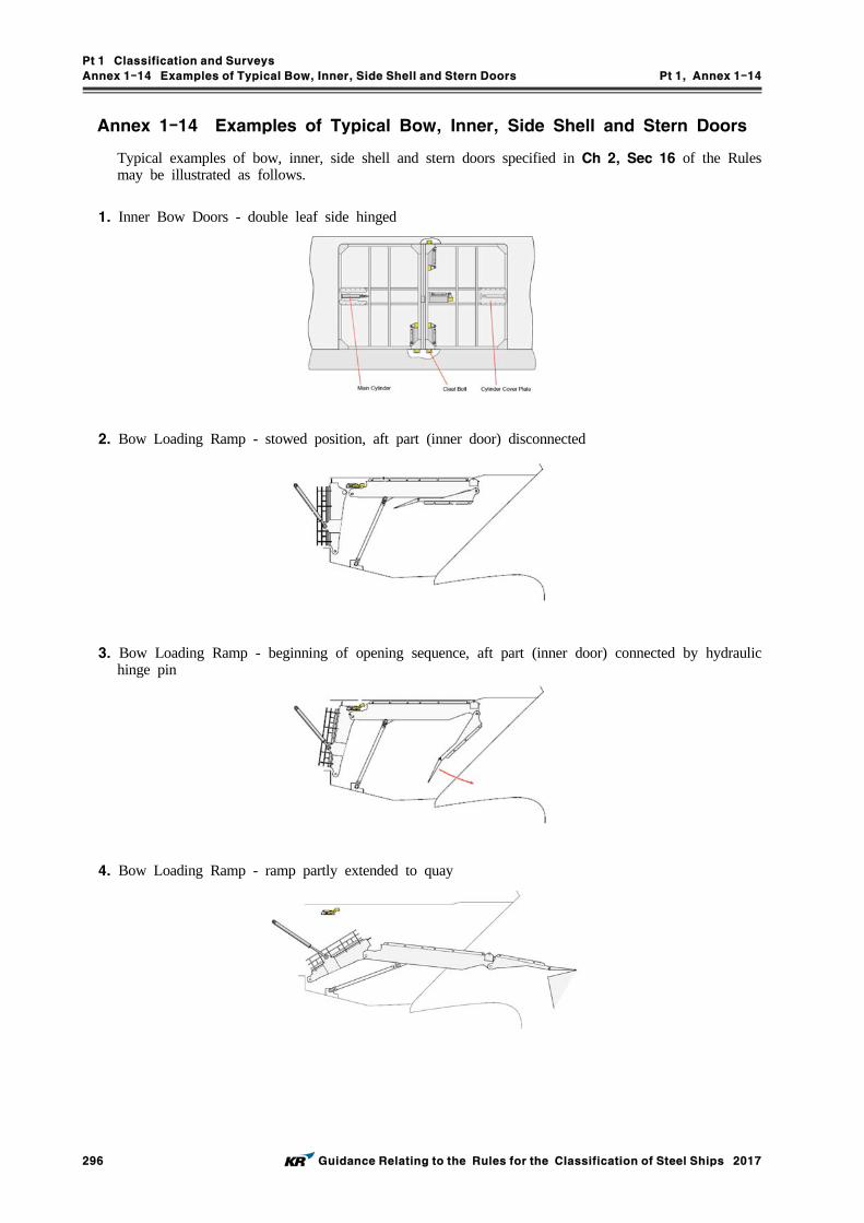
Pt 1 Classification and Surveys
Annex 1-14 Examples of Typical Bow, Inner, Side Shell and Stern Doors Pt 1, Annex 1-14
296 Guidance Relating to the Rules for the Classification of Steel Ships 2017
Annex 1-14 Examples of Typical Bow, Inner, Side Shell and Stern Doors
Typical examples of bow, inner, side shell and stern doors specified in Ch 2, Sec 16 of the Rules may be illustrated as follows.
1. Inner Bow Doors - double leaf side hinged
2. Bow Loading Ramp - stowed position, aft part (inner door) disconnected
3. Bow Loading Ramp - beginning of opening sequence, aft part (inner door) connected by hydraulic hinge pin
4. Bow Loading Ramp - ramp partly extended to quay

Pt 1 Classification and Surveys
Annex 1-14 Examples of Typical Bow, Inner, Side Shell and Stern Doors Pt 1, Annex 1-14
Guidance Relating to the Rules for the Classification of Steel Ships 2017 297
5. Bow Loading Ramp - ramp fully extended to quay
6. Inner Bow Door - single leaf top hinged, type 1
7. Inner Bow Door - single leaf top hinged, type 2

Pt 1 Classification and Surveys
Annex 1-14 Examples of Typical Bow, Inner, Side Shell and Stern Doors Pt 1, Annex 1-14
298 Guidance Relating to the Rules for the Classification of Steel Ships 2017
8. Bow Loading Ramp - side opening bow doors
9. Bow side opening door - closed, side view
10. Bow side opening door - closed, top view
11. Bow side opening door - door panel details

Pt 1 Classification and Surveys
Annex 1-14 Examples of Typical Bow, Inner, Side Shell and Stern Doors Pt 1, Annex 1-14
Guidance Relating to the Rules for the Classification of Steel Ships 2017 299
12. Bow side opening door - open, top view
13. Bow Loading Ramp - visor type bow doors, general arrangement
14. Bow Visor Door - general arrangement

Pt 1 Classification and Surveys
Annex 1-14 Examples of Typical Bow, Inner, Side Shell and Stern Doors Pt 1, Annex 1-14
300 Guidance Relating to the Rules for the Classification of Steel Ships 2017
15. Cleating Hook 1
16. Cleating Hook 2
17. Cleating Wedge

Pt 1 Classification and Surveys
Annex 1-14 Examples of Typical Bow, Inner, Side Shell and Stern Doors Pt 1, Annex 1-14
Guidance Relating to the Rules for the Classification of Steel Ships 2017 301
18. Hydraulic Actuators 1
19. Hydraulic Actuators 2
20. Hydraulic Actuators 3
21. Hydraulic Actuators 4
22. Control Panel - closing door
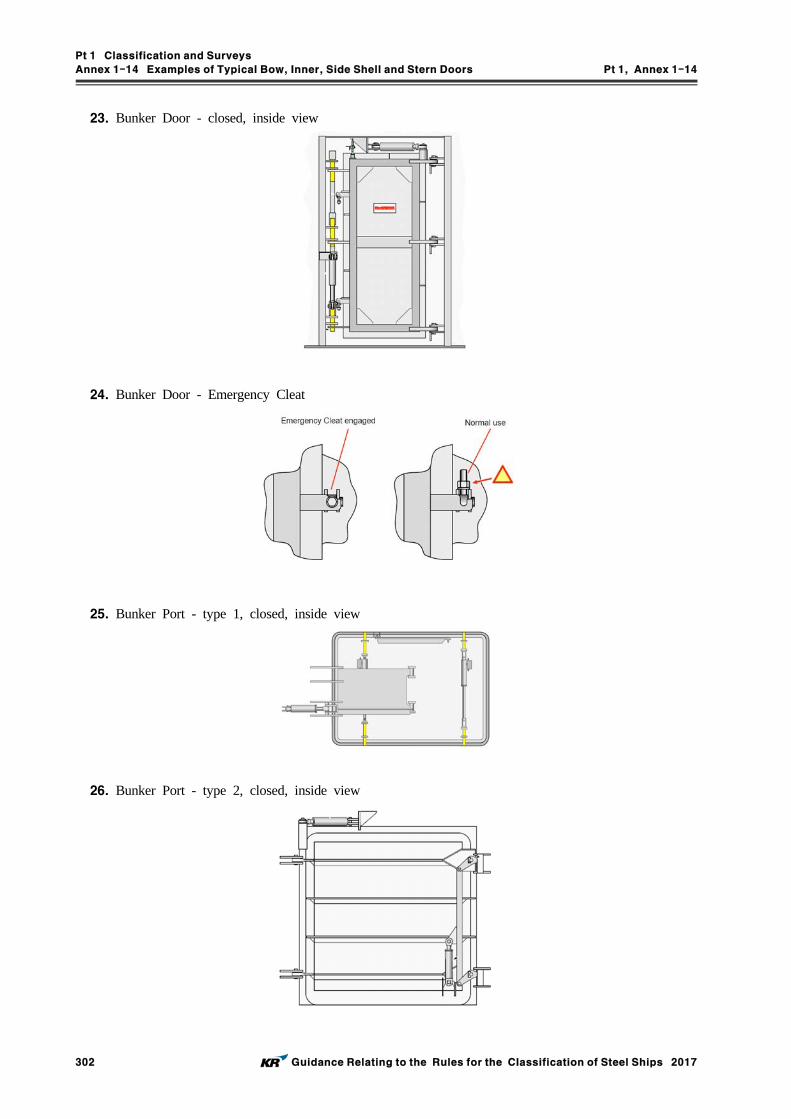
Pt 1 Classification and Surveys
Annex 1-14 Examples of Typical Bow, Inner, Side Shell and Stern Doors Pt 1, Annex 1-14
302 Guidance Relating to the Rules for the Classification of Steel Ships 2017
23. Bunker Door - closed, inside view
24. Bunker Door - Emergency Cleat
25. Bunker Port - type 1, closed, inside view
26. Bunker Port - type 2, closed, inside view
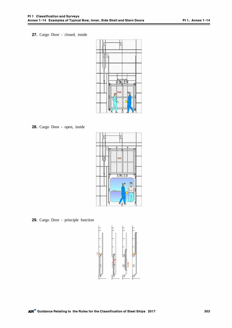
Pt 1 Classification and Surveys
Annex 1-14 Examples of Typical Bow, Inner, Side Shell and Stern Doors Pt 1, Annex 1-14
Guidance Relating to the Rules for the Classification of Steel Ships 2017 303
27. Cargo Door - closed, inside
28. Cargo Door - open, inside
29. Cargo Door - principle function

Pt 1 Classification and Surveys
Annex 1-14 Examples of Typical Bow, Inner, Side Shell and Stern Doors Pt 1, Annex 1-14
304 Guidance Relating to the Rules for the Classification of Steel Ships 2017
30. Cargo Door - top side hydraulic securing device disengaged
31. Cargo Door - top side hydraulic securing device engaged

Pt 1 Classification and Surveys
Annex 1-14 Examples of Typical Bow, Inner, Side Shell and Stern Doors Pt 1, Annex 1-14
Guidance Relating to the Rules for the Classification of Steel Ships 2017 305
32. Side Shell Door - double leaf, closed, inside view
33. Side Shell Door - double leaf, closed, top view
34. Side Shell Door - double leaf, fully opened, top view
35. Side Shell Door - double leaf, half opened, top view
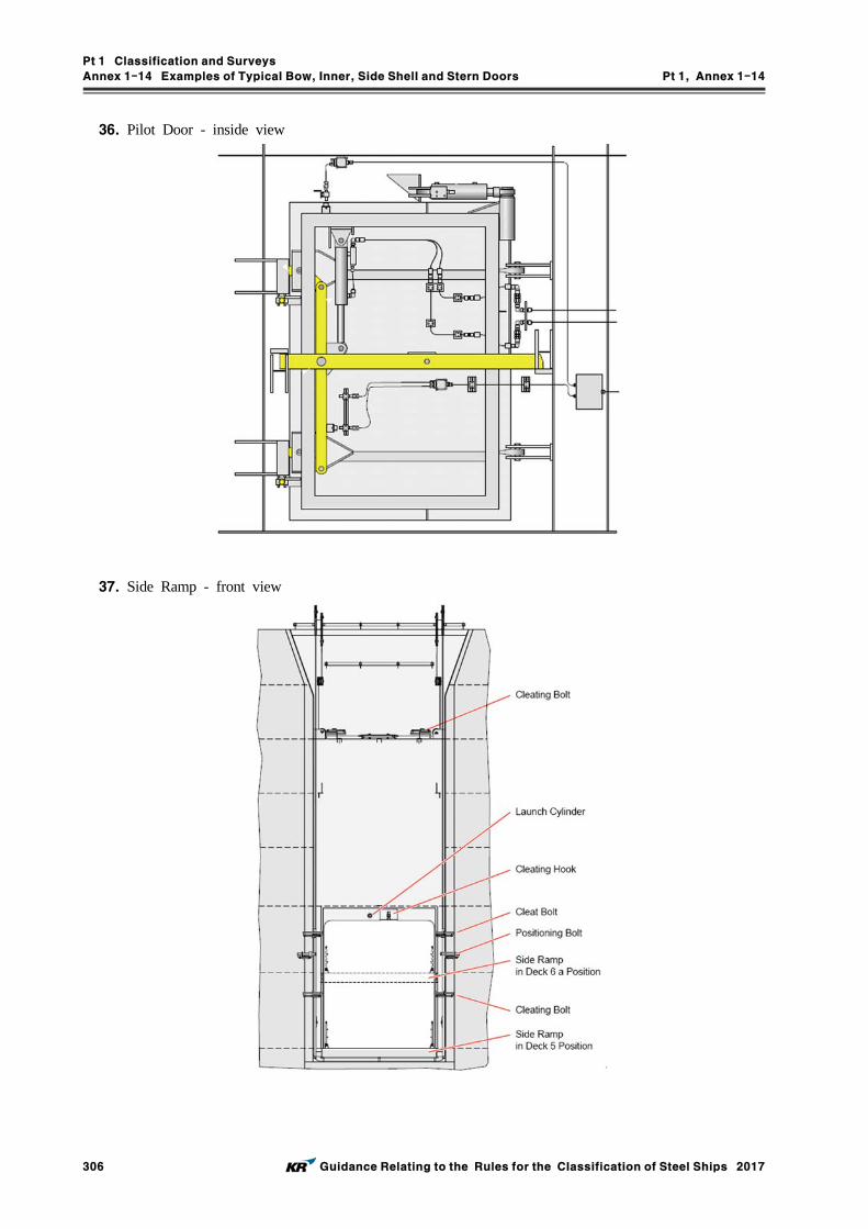
Pt 1 Classification and Surveys
Annex 1-14 Examples of Typical Bow, Inner, Side Shell and Stern Doors Pt 1, Annex 1-14
306 Guidance Relating to the Rules for the Classification of Steel Ships 2017
36. Pilot Door - inside view
37. Side Ramp - front view

Pt 1 Classification and Surveys
Annex 1-14 Examples of Typical Bow, Inner, Side Shell and Stern Doors Pt 1, Annex 1-14
Guidance Relating to the Rules for the Classification of Steel Ships 2017 307
38. Side Ramp - side view
39. Side Ramp - top view

Pt 1 Classification and Surveys
Annex 1-14 Examples of Typical Bow, Inner, Side Shell and Stern Doors Pt 1, Annex 1-14
308 Guidance Relating to the Rules for the Classification of Steel Ships 2017
40. Stern Door - single leaf, closed, car carrier type
41. Stern Door - single leaf, open, car carrier type, top view
42. Stern Door - single leaf, open, car carrier type

Pt 1 Classification and Surveys
Annex 1-14 Examples of Typical Bow, Inner, Side Shell and Stern Doors Pt 1, Annex 1-14
Guidance Relating to the Rules for the Classification of Steel Ships 2017 309
43. Stern Door - double leaf, open, typical cleating arrangement
44. Stern Door - single leaf, open typical cleating arrangement, type 1
45. Stern Door - single leaf, open, typical cleating arrangement, type 2

Pt 1 Classification and Surveys
Annex 1-14 Examples of Typical Bow, Inner, Side Shell and Stern Doors Pt 1, Annex 1-14
310 Guidance Relating to the Rules for the Classification of Steel Ships 2017
46. Stern Door - single leaf, closed, inside view, typical cleating arrangement, type 3
47. Stern Door - single leaf, closed, typical cleating arrangement, type 3
48. Stern Door - single leaf, open, push-out cylinder arrangement

Pt 1 Classification and Surveys
Annex 1-14 Examples of Typical Bow, Inner, Side Shell and Stern Doors Pt 1, Annex 1-14
Guidance Relating to the Rules for the Classification of Steel Ships 2017 311
49. Stern Door - single leaf, open, typical cleating arrangement, type 3

Pt 1 Classification and Surveys
Annex 1-15 Requirements for CLEAN Notation Pt 1, Annex 1-15
312 Guidance Relating to the Rules for the Classification of Steel Ships 2017
Annex 1-15 Requirements for CLEAN Notation
1. General
(1) This Annex applies to the ships classed with the Society or intended to be registered under the Society, which intended to comply with the environmental protection requirements for design, construction and operation for obtaining the relevant notation.
(2) The notation prescribed in (1) are classified into the followings.(A) CLEAN1 notation: Ships complying with requirements of convention specified in Par 3(B) CLEAN2 notation: Ships complying with additional requirements of the Society specified in
Par 4(C) CLEAN3 notation: Ships complying with additional requirements in Par 5
2. Survey
(1) Classification survey(A) The documents specified in applicable requirements for each notation are to be submitted to
the Society.(B) The appropriate installation of all relevant equipment specified in applicable requirements for
each notation and the proper provision on board of all relevant documents, procedures and record books are to be confirmed.
(2) Periodical survey(A) The periodical surveys to maintain the classification are to be carried out at Annual Survey,
Intermediate Survey and Special Survey. However, the survey for MARPOL Annex IV and V is to be carried out at Special Survey and the periodical survey for AFS convention is not required.
(B) The satisfactory condition of all relevant equipment specified in applicable requirements for each notation and proper maintaining of all relevant documents, procedures and record books are to be confirmed.
3. CLEAN1 notation
For obtaining CLEAN1 notation, the ship is to be in compliance with applicable requirements of MARPOL Annex I, II, IV, V and VI and AFS convention.
4. CLEAN2 notation
For obtaining CLEAN2 notation, the ship is to be in compliance with documents requirements of Table 1 and applicable requirements of Table 3 for applicable convention in addition to Par 3.
5. CLEAN3 notation
For obtaining CLEAN3 notation, the ship is to be in compliance with additional documents require-ments of Table 2 and additional requirements of Table 4 in addition to Par 4.

Pt 1 Classification and Surveys
Annex 1-15 Requirements for CLEAN Notation Pt 1, Annex 1-15
Guidance Relating to the Rules for the Classification of Steel Ships 2017 313
ItemsPlans and documents to be submitted Certificate/
Statement of ComplianceFor approval For review
Marine pollution prevention
Oil
Arrangements of tanks which are to be protected in accordance with Par 2 of Oil item in Table 4
Type approval certificate of oil filtering equipment in accordance with Par 1 of Oil item in Table 4
Air pollution prevention
Emission to air
Type approval certificate of incinerator in accordance with Par 3 of Emission to air item in Table 4
Table 2 Additional documentation requirements for CLEAN3 notation
ItemsPlans and documents to be submitted Certificate/
Statement of ComplianceFor approval For review
Marine pollution prevention
Oil (related to MARPOL Annex I)
Arrangement for cargo and oil loading and discharge manifold, including drip trays and drainage systems
(1) Bunkering procedures(2) Bilge water management
plan
IOPP Certificate
Noxious Liquid Substances (related to MARPOL Annex II)
Arrangement for cargo and oil loading and discharge manifold, including drip trays and drainage systems
NLS Certificate or IBC/BCH Statement of Compliance
Sewage (related to MARPOL Annex IV)
Sewage management plan ISPP Certificate or Statement of Compliance
Garbage (related to MARPOL Annex V)
Garbage management plan
Air pollution prevention
Emission to air(related to MARPOL Annex VI)
Piping diagram for refrigeration and airconditioning systems
(1) Fuel oil management plan(2) Ozone depleting
substances management procedure, if necessary
IAPP Certificate
Energy Efficiency(related to MARPOL Annex VI)
IEE Certificate/ Statement of Compliance
Preventingdestruction ofthe ecosystem
Anti-Fouling Systems (related to AFS Convention)
Biofouling management plan IAFS Certificate/ Statement of Compliance
Ballast water management(related to BWM Convention)
IBWMCertificate/ Statement of Compliance
Ship recycling
Ship recycling(related to Ship Recycling Convention)
IIHM Certificate/ Statement of Compliance
Safety management system
Safety management system (related to ISM Code)
SMC
Table 1 Documentation requirements for CLEAN2 notation

Pt 1 Classification and Surveys
Annex 1-15 Requirements for CLEAN Notation Pt 1, Annex 1-15
314 Guidance Relating to the Rules for the Classification of Steel Ships 2017
Items Requirements
Marine pollution prevention
Oil
1. For machinery spaces, the following requirements are to be complied with:(1) Fuel oil tanks, lubricating oil tanks and other oil tanks, which are mechanically
filled by pumps, etc., are to be equipped with high level alarm to prevent overfilling.
(2) Oil filtering equipment for machinery spaces is to be provided with arrangements to ensure that any discharge of oily mixtures is automatically stopped in cases where the oil content of effluents exceeds 15 .
(3) Drip trays with capacities of at least the following are to be fitted under all vents and filling manifolds for fuel oil tanks, lubricating oil tanks, other oil tanks:(A) for vessels less than 1600 gross tonnage: 80 ℓ(B) for vessels equal to or larger than 1600 gross tonnage: 159 ℓ
(4) Bilge water management plan is to be place onboard. This plan is to include the following.(A) Vessel name and class number(B) Type and size of vessel(C) Bilge water treatment procedure and system arrangement
2. For cargo area of oil tankers, the following requirements are to be complied with:(1) Each cargo tank is to be fitted with a high level alarm and an overfill alarm, and
the overfill alarm is to be independent of the tank gauging system.(2) All cargo manifolds are to be fitted with drip trays with means for drainage to a
appropriate tank onboard. The drip trays is to have the following capacities:- length: beyond forward and aft ends of the manifold- width: at least 1800 , though such that the spill tray extends at least 1200
outboard of the end of the manifold flange- depth: minimum depth 300
(3) Coamings are to be fitted on deck in accordance with Pt 8, Ch 2, 401. 6 of the Rules.
(4) Requirements in Pt 7, Ch 1, 1002. 7 (4) of the Rules are to be complied with.3. Ships are to be classed with Emergency Response Service System of the Society or
any society which is subject to verification of compliance with QSCS(Quality System Certification Scheme) of IACS.
Noxious Liquid Substances
1. NLS tankers defined in MARPOL Annex II/16.9 are to be comply with the following requirements.
(1) All cargo manifolds are to be fitted with drip trays with means for drainage to a appropriate tank onboard. The drip trays is to have the following capacities:- length: beyond forward and aft ends of the manifold- width: at least 1800 , though such that the spill tray extends at least 1200
outboard of the end of the manifold flange- depth: minimum depth 300
(2) Coamings are to be fitted on deck in accordance with Pt 7, Ch 6, 307. 7 of the Rules.
(3) Piping systems serving permanent ballast tanks are to be independent of piping systems serving cargo tanks and of cargo tanks themselves in accordance with Pt 7, Ch 6, 305. 1 of the Rules.
Sewage
1. Sewage system ventilation pipes are to be independent from other ventilation piping systems.
2. A sewage management plan is to be placed onboard. This plan is to include the following.
(1) Vessel name and class number(2) Diagrams and component description of the sewage system(3) Instructions for the operation and management of the sewage system
3. The recorded data shall include, as a minimum, date of discharge; quantity of sewage discharge; location and type of reception facility; and for sea discharges, the distance to the nearest land and the vessel’s speed.
GarbageA garbage management plan in accordance with IMO Res.MEPC.220(63) is to be placed onboard.
Table 3 Requirements for CLEAN2 notation

Pt 1 Classification and Surveys
Annex 1-15 Requirements for CLEAN Notation Pt 1, Annex 1-15
Guidance Relating to the Rules for the Classification of Steel Ships 2017 315
Items Requirements
Air pollution prevention
Emission to air
1. Fuel oil management plan is to be placed onboard. This plan is to include the following.
(1) Vessel name and class number(2) fuel oil quality complying with MARPOL) Annex VI/18.3(3) Those vessels using separate fuels when entering or leaving an ECA are to
include in the fuel oil management plan the following:(A) Procedures on how to perform the fuel oil changeover(B) Diagrams of the fuel oil system including details of change over(C) Methods and means of recording volume of low-sulfur fuel oils in tanks,
and date, time, and position of the vessel when any operation of fuel oil changeover
2. Refrigerating facilities and air-conditioning equipment using ozone depleting sub-stances are to comply with the following.
(1) Annual refrigerant leakage is to be not more than 10% in mass() of the total refrigerant charge of each system.
(2) At least one gas detector is to be provided to spaces into which the re-frigerant in facilities could leak. The detection is to give an visible and audi-ble alarm in a manned location when the refrigerant concentration exceeds a predetermined limit(for example, 25 for ammonia or 300 for halo-genated fluorocarbons).
(3) For refrigerant recovery, refrigerant compressors are to be capable of evacuat-ing a system charge into an storage container and capacity of this storage container is to be at least 125% of the largest volume of discharged refrigerant.
(4) A Ozone depleting substances management procedures is to be placed on-board if necessary. This procedure is to include:(A) Vessel name and class number(B) Diagrams and component description of all refrigerant systems(C) Procedures detailing the means to control the loss, leakage, venting, and
disposal of refrigerants(D) Methods and means of recording refrigerant inventory
(a) Supply of refrigerant onboard(b) Discharge of refrigerant to the atmosphere due to leaks or system
maintenance(c) Recovered refrigerant including its storage location(d) Refrigerant disposal to land-based reception facilities
(E) Refrigerants data sheet(F) Specification of fire fighting systems, including data sheet for extinguish-
ing media3. Portable and fixed fire extinguishing systems are not to include halon 1211,
1301, 2402 and perfluorohydrocarbons.4. Where installed onboard, incinerators are to be type-approved in accordance with
IMO Res.MEPC.76(40) or Res.MEPC.244(66) whichever is applicable to the ship.
Energy Efficiency
An IEE Certificate or Statement of Compliance is to be issued and maintained.
Preventingdestruction ofthe ecosystem
Anti-Fouling Systems
A biofouling management plan recommended in IMO Res.MEPC.207(62) is to be placed onboard.
Ballast water management
An IBWM Certificate or Statement of Compliance is to be issued and maintained.
Ship recyclingShip recycling
An IIHM Certificate or Statement of Compliance is to be issued and maintained.
Safety management system
Safety management system
A SMC is to be issued and maintained.
Table 3 Requirements for CLEAN2 notation (Continued)

Pt 1 Classification and Surveys
Annex 1-15 Requirements for CLEAN Notation Pt 1, Annex 1-15
316 Guidance Relating to the Rules for the Classification of Steel Ships 2017
Items Requirements
Marine pollution prevention
Oil
1. Oil filtering equipment is to be provided with automatic stopping arrangements are to be provided for any discharge of oily mixtures when the oil content in the ef-fluent exceeds 5 .
2. Lubricating oil tanks and hydraulic oil tanks are to comply with the requirements of MARPOL Annex I/12A.
Noxious Liquid Substances
1. NLS tankers defined in MARPOL Annex II/16.9 are to be comply with the follow-ing requirements.
(1) The arrangements of cargo tanks are to comply with the double hull and dou-ble bottom requirements of a Type 2 ship specified in Pt 7, Ch 6, 206. 1 (2) of the Rules unless a Type 1 ship is to comply with requirements of a Type 1 ship.
(2) Gauging systems for cargo tanks are to be of closed device specified in Pt 7, Ch 6, 1301. 1 (3) of the Rules.
GarbageShips are not to dispose of food wastes into the sea except when they have been passed through a comminuter or grinder.
Air pollution prevention
Emission to air
1. Refrigerants and Fire-extinguishing Medium used onboard are to be of the following.
(1) Ozone depleting potential(ODP) = 0(2) Global warming potential(GWP) < 2000
2. Tankers carrying crude oil or petroleum product with flash point less than 60℃
are to have VEC2 notation.3. At least one incinerator is to be installed onboard and is to be type approved in
accordance with IMO Res.MEPC.76(40) or Res.MEPC.244(66).
Table 4 Additional requirements for CLEAN3 notation

Rules for the Classification of Steel ShipsGuidance Relating to the Rules for the Classificationof Steel Ships
PART 1 CLASSIFICATION AND
SURVEYS
Published by
KR
36, Myeongji ocean city 9-ro, Gangseo-gu,
BUSAN, KOREA
TEL : +82 70 8799 7114
FAX : +82 70 8799 8999
Website : http://www.krs.co.kr
CopyrightⒸ 2017, KR
Reproduction of this Rules and Guidance in whole or in parts is prohibited without permission of the publisher.