2 Hydraulic power units, horizontal, variable … · 4 Hydraulic power units, horizontal, variable...
39
Transcript of 2 Hydraulic power units, horizontal, variable … · 4 Hydraulic power units, horizontal, variable...


2 Hydraulic power units, horizontal, variable displacement pumps BOSCH @
B a
Bar Manifold
\
\
Air lther/F
Cap
/ ‘iller
/
/
/
Pump/Motor Assembly
/ /
Jt
G —.—————
iage/lsolat( Assembly
Reservoir Oil Level Gage with Thermometer

@ BOSCH Hydraulic power units, horizontal, variable displacement pumps 3
A complete standard power unit program featuring: 1
•l Steel reservoir sizes 35, 60 and 100 gallons.
•l Vane and radial piston type pumps with flow rates of 7.5 to 30.3 GPM.
q System pressures ranging from 400 to 4060 PSI.
El Horizontal shock mounted, electric motors, in sizes from 3 to 75 HP.
q In-tank return line filter with removable bowl.
q Oil level gage with thermometer for easy check of fluid level and temperature.
q Optional bar manifolds, heat exchanger and/or accessories can be specified to form a complete compact system.
q All units are fully assembled, tested and painted.

4 Hydraulic power units, horizontal, variable displacement pumps BOSCH @
1 Index
Tank Size ~ Pump Flow Rate Motor Size Page Number
35 Gallon 7.42to 11.36 GPM 3 to 20 HP 6 (133 Liter) (28.06 to 43.00 LPM)
60 Gallon I 14.77 to 20.83 GPM 1
7.5 to 40 HP 1
16 (228 Liter) (55.9 to 78.73 LPM)
100 Gallon I 29.09 to 30.3 GPM 1
15t075HP 1
24 (380 Liter) (1 10.11 to 114.69 LPM)
Specifying / Ordering Procedure:
1. Pump Flow Rate/ Tank Size Start selection process in the Index above. The Pump Flow Rate/ Tank Size
will lead to the catalog page for the Hydraulic Power Unit required.
2. Pump Type/ Pressure/ Based upon selection in step one, the first page of that section features the Horsepower Selection Chart / Ordering Part Numbers. This chart enables a part number to be
determined for a Basic Power Unit, without pump, chosen by Pump Type, Horsepower and Pressure Rating. Specify this part number on purchase order.
3. Pump Selection This chart lists various control options for vane and Radial Piston Pumps to be used with the basic Power Unit. Specify this part number on purchase order.
4. Manifold Selection Cart/ Select manifold type and any accessory required from these charts. Part numbers Accessory Selection for directional, Modular and Proportional control valves will be found in the corre-
sponding Engineering catalogs. Specify these part numbers on purchase order
5. Specifying Example: If requirements are: l a flow rate of 7 GPM, l a 35 gallon tank, l a maximum working pressure of 3000 PSI
The Index would lead to page 6 of this catalog. In the Selection Chart/Ordering Part Numbers, a Radial Piston Pump 0.98 c.i. displacement and an electric motor rated at 20 HP will deliver the 3000 PSI required. Part number 9815230372 would be used as the ordering number for the Basic Power Unit. This part number along with the part number of the pump, manifold and any combination of accessories, including control valves, should be listed as individual line items on purchase order.

@ BOSCH Hydraulic power units, horizontal, variable displacement pumps 5
Technical Specifications
General
Tank Sizes 35, 60 and 100 Gallon (1 33, 228 and 280 Liters) Welded Steel
Hydraulic Pumps 7,5 to 30,3 GPM
Electric Motors 3 to 75HP at 1750 PRM, C-Face, TEFC 230/460/3/60
Installation Position Horizontal Mount Pumo/Motor Grou~
Operating Pressure Reference Individual Basic Power Unit
Hydraulic Fluid Premium Grade Hydraulic Oil with Anti-Wear Additives (Others on Request)
Viscosity Minimum Optimum Maximum Maximum Operating Operating Operating Start-up Viscosity Viscosity Viscosity Viscosity
VPV-16 loosus 150-250 SUS 1000 Sus 4000 Sus Sv-1 o, 21 cST 32-54 cST 216 cST 864 cST 15, 20, 25
SV-40 150 Sus 200-300 SUS 1000 Sus 4000 Sus 32 cST 43-65 cST 216CST 864cST
RKP-16, 66 Sus 215 SUS 460 SUS 2600 SUS 32,45, 63 12 cST 46 cST 100 cST 500 cST
I Fluid Temperature I +5to+176° F (-15 to+80° C) I Seals Buns N
Standard Equipment
Accessories
Tank, Steel Cover, Drain Plug, Oil Level Gage with Thermometer, Cleanout Cover, Filler/Air Breather, Motor Group Assembly: Shock Mounted, Drain Connection, Intank Return Line Filter: 10 Micron, Relief Valve Manifold Mount with Gage Port
Pump, Filter Clogging indicators, Heat Exchanger, Water Valve with Bulbwell, Water Strainer, Air Bleed (Recommended for Vane Pumps), Float Switch, Temperature Switch with Bulbwell, Heater with Bulbwell, Bar Manifold: 1 to 5 Station, Gaqe Isolator Assemblv
Valving Reference Bosch Catalogs for Directional, Modular, and Proportional Control Valves.
Scope of Supply Units are completely assembled, as selected from the following selection charts, tested and ~ainted
I Reference Catalocrs I
Vane Pumps sv lo&15 AKY 003/1 US Sv 20 AKY 00312 US Sv 40 AKY 003/3 US
Radial Piston Pump RKP 16,32, 45 &63 AKY 002/2 US
Relief Valve AKY 00711
Directional Control Valves D03 (NG6) HPUS AKY 006/4 US D05 (NG 10) HPUS AKY 006/1 8 US D07 (NG 16) HPUS AKY 006/5 US
Modular Valve D03 (NG 6) AKY 01 0/1 US D05 (NG 10) AKY 01 0/1
1 Proportional Control Valve
1
D03 (NG6) & D05 (NG1 O) AKY 013/1 EN I
I Price I I SEE “PRICE LIST HYDRAULIC POWER UNIT, HORIZONTAL MOUNT, VARIABLE DISPLACEMENT PUMPS” HPUS-AkYO04/4PUS I
Product Literature Disclaimer
I SPECIFICATIONS AND/OR DIMENSIONS ARE SUBJECT TO CHANGE WITHOUT PRIOR NOTICE. PLEASE CONSULT FACTORY. I

6 Hydraulic power units, horizontal, variable displacement pumps BOSCH @
35 Gallon / 133 Liter Steel Tank
Selection Chart/Ordering Part Numbers
Tank Pump Pump Flow Motor Pressure Max @ HP Basic Power
Size Designation Displacement @l 750 RPM HP Unit without
Gallon ln3/Rev GPM Pump
(Liter) (cm’/Rev) (L/rein) Psl bar Part Number
35 Sv-1 o 7.58 3 500 35 9 815 230 355 (1 33) Vane Pump ;1 6.39) (28.69) 5 940 65 9 815 230 356
7112 1410 97 9 815 230 357 10 1880 130 9 815 230 358 15 2000 138 9 815 230 359
Sv-15 1.5 11.36 5 630 43 9 815 230 360 Vane Pump (24,58) (43) 7112 940 65 9 815 230 361
10 1260 87 9 815 230 362 15 1500 103 9 815 230 363
VPV-16 7.58 5 940 65 9 815 230 364 Vane Pump /1 6.39) (28.69) 71/2 1410 97 9 815 230 365
10 1880 130 9 815 230 366 15 2000 138 9 815 230 367
RKP-16 .98 7.42 5 960 66 9 815 230 368 Radial Piston (16) (28.08) 7112 1440 99 9 815 230 369 Pump 10 1920 132 9 815 230 370
15 2880 199 9 815 230 371 20 4050 280 9 815 230 372
Pump Selection Chart
Vane Pump SV-10 SV-15 VPV-16
Pressure Compensator Part Number Part Number Part Number
Control Descrbtion
I Sinde Stage 6928981 I 6928985 I 0 514 300 203 I 2-Stage 6928904 6928912 0 514 300 211
Solenoid 2-Pressure 6928924 6928923 Consult factory
Normally Low Energy Hiah
I Load Sensing I 6928907 I 6928915 I Consult factory I
I Torque Limiting I 6928918 I 6928220 I Consult factory I
Radial Piston Pump RKP-16
Pressure Compensator Control Descrbtion Part Number
Adjustable 0 514 300 287
Remote 0 514 300 289
I Pressure and Flow I 0 514 300 323 I
Constant HP Consult Factory J

@ BOSCH Hydraulic power units, horizontal, variable displacement pumps 7
1 Pump Control Manifold Selection Chart I Manifold Type Reference Description Part Number
Flow Control Manifold See page 38. Load Sense Flow Control 9 815 232 921
Pressure and Flow Control See page 38. Combined Pressure and 9 815 232 922 manifold Flow Control
Proportional Control Valve See page 38. See Catalog NG6 and Select from catalog. NG1 O Proportional
I Bar Manifold Selection Chart 1
Manifold Type
P I Bar Manifold D05 (NG1O)
I Directional Control Valves
I Modular Control Valves
Reference
See page 35,
See page 36.
See page 35& 36.
See page 35 & 36.
1 Accessory Selection Chart !
Description
1 Valve Station 2 Valve Station
3 Valve Station
4 Valve Station
5 Valve Station
1 Valve Station
2 Valve Station
3 Valve Station 4 Valve Station
5 Valve Station
See Catalog Directional Control Valve
See Catalog Directional Control Valves
Part Number
Aluminum
(3000PSI Max)
9 815 232 901 9 815 232 902 9 815 232 903 9 815 232904 9 815 232 905
9 815 232 911 9 815 232 912 9 815 232 913 9 815 232 914 9 815 232 915
DuraBar
9 815 232 906 9 815 232 907 9 815 232 908 9 815 23 2909 9 815 232 910
9 815 232 916 9 815 232 917 9 815 232 918 9 815 232 919 9 815 232 920
Select from catalog.
Select from catalog.
Accessory Reference Description Model Part Number
Filter Clogging Indicator See page 32. Optical Gage 9 815 230 106 Electrical (Pressure Switch), 250 VAC, 22 PSI RB5-03 9 815 230 107 Electrical w/Light (DIN Plug w/Light 24 Volt DC) 9 815 230 108 Electrical w/Light (DIN Plug w/Light 115 Volt AC) 9 815 230 109 Electrical w/Light (DIN Plug w/Light 230 Volt AC) 9 815 230 110
Heat Exchanger See page 32, Water to Oil 10-RB5-30 9 815 232 947
Water Valve See page 33, Modulating Valve with Bulbwell 3 /4 RB5 -45-B 9 815 230 112
Water Strainer See oaae 33. 3/4 RB5-43 9 815 232 948 ,“
-,
Air Bleed Valve See page 33. Recommended For Vane Pumps RB6-37 9 815 232 949
Float Switch See page 33. Normally closed dry RB4-26 9 815 232 950 Normallv o~en drv 9 815 232 951 .,, I
Temperature Switch See page 34. Single Contact RB4-40-B 9 815 232 952 I Double Contact 9 815 232 953
Heater See page 34. Heater with Bulbwell (Specify voltage.) RB5-40 9 815 232 954
Pressure Gage See page 34, Gage Isolator Assembly RB4-05 9 815 232 955
I

8 Hydraulic power units, horizontal, variable displacement pumps BOSCH @
Standard Equipment
1. Tank
2. Tank drain connection
3. Oil level gage with thermometer
4. Clean out cover
5. Filler/Air breather
6, Motor/Pump group, shock mounted
7, Auxiliary return connection
8, Return filter, intank mounted
9, Relief valve, manifold mounted
10, Hydraulic pump
DR –
f
-P
1
– GA
T T–
—.. — .—. -—- -—- .— - .— - - --— --— --— --— --— --— -- #8 SAE
r
--— -- SEE CHART FOR #4 SAE
7 #16 SAE
PRESSURE PORT SIZE —-- —-- — -- 1
[ - --y
i TI@$_
,
,Ig
,
I
_–j-–;’ -- -i_
-; T -- 1.- ---- --, :1 , 1 --
‘$
--- 1 j: ,, ‘* 1, ~ i! ! ._h \ - 1 11 1 \ \ ; ~[- L_--ll ----- ----- ----- - :
I
--i-i-----+------~, : 10’ I
4(r 1’-------’-1: TO’ & 2#16SAE
PRESSURE PORT SIZE CHART
RADIAL PISTON PUMP – 3/4” CODE 614 BOLT FLANGE
VANE PUMP - #12 SAE STRAIGHT THREAD
* VPV 16 WITH SHOCK CLIPPER SHOWN

@ BOSCH Hydraulic power units, horizontal, variable displacement pumps 9
I Optional Accessories I
1 though 10 see preceding page
11, Optical indicator
12, Electrical indicator
13, Electrical indicator with light
14, Heat exchanger
15. Water valve with bulbwell
16. Water strainer
17. Arr bleed (recommended for vane pumps)
18. Float switch
19. Temperature switch with/bulbwell
20. Heater with bulbwell
21. Bar manifold 1 to 5 station
22. Gage/Isolator assembly
—
VU(O3
___ ___ --- __
~~ ) Iu
xl —-- --— ---— ---— - ‘-’21 1
I I
j x
I
I a; .- —--— -- —--
!t$- UT
:~--;-~---J--__;, I ‘--+-L-.4. ‘-i’
I 1 I I 1 , I 1 , , t
W ! 13-;9 .
I I k’2
l VPV 16 WITH SHOCK CLIPPER SHOWN

10 Hydraulic power units, horizontal, variable displacement pumps BOSCH @
35 Gallon Unit withVPV-16
1. Tank Inches (Millimeters)
2, Tank drain connection
3, Oil level gage with thermometer
4. Clean out cover
5. Filler/Air breather
6. Motor/Pump group, shock mounted
7. Auxiliary return connection
8. Return filter, intank mounted
9. Relief valve, manifold mounted
10. Hydraulic pump
m + 3 HP= 31.50
(800,10)
5 HP= 31.50 (800.10)
7.5 HP= 32.75 (831 .85)
10 HP= 3275 (831 .85)
m 15 HP= 3500 (889.00)
20 HP= 3500 (889.00)
-L- H
7#8SAE@ 8 —
u
6
9 1 T
~. -.,
10 11 1 1 1 1 G- ...
, d r 1 /2” DRIP 5
L
L ‘-l I II II I
II
4 ‘ T
3
ID [( BOSCH )] I
LIP
(Selection of pump and it’s control may affect overall dimensions.)

@ BOSCH Hydraulic power units, horizontal, variable displacement pumps 11
35 Gallon Unit with VPV=16 and Optional Accessories
1 though 10 see preceding page
11.
12.
13.
14.
15.
16.
17.
18.
19.
20.
21.
22.
—
Optical indicator
Electrical indicator
Electrical indicator with light
Heat exchanger
Water valve with bulbwell
Water strainer
Air bleed (recommended for vane pumps)
Float switch
Temperature switch with/bulbwell
Heater with bulbwell
Bar manifold 1 to 5 station
Gage/Isolator assembly
3 HP= 31.50 (800,10)
5 HP= 31”50 (800.10)
7.5 HP= 32.75 (831.85)
10 HP= 32.75 (831 .85)
15 HP= 3500 (889.00)
20 HP= 35.00 (889.00)
i---
L-----&:g::o) + 28.75
(730.25)
(Selection of pump and it’s control may affect overall dimensions.)
Inches (Millimeters)
Customer connections see pages 35 and 36
8 1 11
12 13
20
J 1 6
R-’Tfi? ‘ o 9
.
0 b.’ ~.-q o
11 II 11 0 ----
5
I v 2 #16 SAE
\
k L---+!!5,,0J--J 35.00
(889.00) 41.00
(1041,4)
r 1 /2” DRIP LIP
T T’_
20.50 (520.70)

12 Hydraulic power units, horizontal, variable displacement pumps BOSCH @
35 Gallon Unit with SV-1 O
1, Tank Inches (Millimeters)
2. Tank drain connection
3. Oil level gage with thermometer
4. Clean out cover
5. Filler/Air breather
6. Motor/Pump group, shock mounted
7. Auxiliary return connection
8. Return filter, intank mounted
9. Relief valve, manifold mounted
10. Hydraulic pump 7 #8 SAE
@8
3 ‘p = (:;0%3 5 ‘p= (::0%)
7“5 ‘p = ({;1;{5)
‘ 0 ‘p = (:%,.8;)
‘ 5 ‘p = (@gC)))
20 ‘p = (889.00)
I
e) +
~ Al L(,,6%-J 24.00
(609.60)
25.25 (641 ,35)
6
~ J
~---,
:: L---,
1 /2” DRIP
5 $,
lo ‘ jf
T 4
3
BOSCH 1
20.50 (520.70)
w 2 #16 SAE
-1
~L(W’lj (889,00)
LIP
(Selection of pump and it’s control may affect overall dimensions.)

@ BOSCH Hydraulic power units, horizontal, variable displacement pumps 13
I 35 Gallon Unit with SV-1 O and Optional Accessories ~
1 though 10 see preceding page
11. Optical indicator
12. Electrical indicator
13. Electrical indicator with light
14. Heat exchanger
15. Water valve with bulbwell
16. Water strainer
17. Air bleed (recommended for vane pumps)
18. Float switch
19. Temperature switch with/bulbwell
20. Heater with bulbwell
21. Bar manifold 1 to 5 station
22. Gage/Isolator assembly
IL Al “L(,,,,,)d 24.00
(609.60)
28.75 (730,25)
Inches (Millimeters)
Customer connections see pages 35 and 36
8 11 12 13
20
P LIP
)
L!!=i!E!l (Selection of pump and it’s control may affect overall dimensions.)

14 Hydraulic power units, horizontal, variable displacement pumps BOSCH @
35 Gallon Unit with RKP-16
1. Tank Inches (Millimeters)
2. Tank drain connection
3. Oil level gage with thermometer
4. Clean out cover
5. Filler/Air breather
6. Motor/Pump group, shock mounted
7. Auxiliary return connection
8, Return filter, intank mounted
9. Relief valve, manifold mounted
10. Hydraulic pump
7 #8 SAE
98
I 3 ‘p = (s0%)
6 9 -
1
1 /2” DRIP
?
r
20.50 (520.70)
A
~(&%+ (889.00)
LIP
(Selection of pump and it’s control may affect overall dimensions.)

@ BOSCH Hydraulic power units, horizontal, variable displacement pumps 15
35 Gallon Unit with RKP-16 and Optional Accessories
1 though 10 see preceding page
11,
12.
13,
14.
15,
16,
17.
18.
19.
20.
21.
22.
3
5
7.5
10
15
20
Optical indicator
Electrical indicator
Electrical indicator with light
Heat exchanger
Water valve with bulbwell
Water strainer
Air bleed (recommended for vane pumps)
Float switch
Temperature switch with/bulbwell
Heater with bulbwell
Bar manifold 1 to 5 station
Gage/Isolator assembly
Unl I---b A/---\
I
‘“-”.”:’_”’ m-i I J I hi--l ~ 1 ,0..,., d m-l + 1) H;= 31.50
HP= 31.50 (800.10)
+p= 32.75 (831 .85)
,-. A n. r
!H ‘p= (;;i~J5) I Hp = 35.00
(889.00) Hp = 35.00
(889.00) @~
Inches (Millimeters)
Customer connections see pages 35 and 36
I 14 15
Jrf%J 7’8sAE@ F-1 1%
20 I J
@j
1-!= +(&?5%jo)----- 35.00
(889.00) 41.00
(1041.4)
1/2” DRIP LIP
\
r
20.50 (520.70)
(Selection of pump and it’s control may affect overall dimensions,)
—

16 Hydraulic power units, horizontal, variable displacement pumps BOSCH @
1 60 Gallon/228 Liter Steel Tank I Selection Chart/Ordering Part Numbers
Tank Pump Pump Flow Motor Pressure Max @ HP Basic Power Unit Size Designation Displacement (Q1 750 RPM HP Gallon In’/Rev
Without Pump GPM Parl Number
(Liter) (cm’/Rev) (L/rein) Psi bar
60 SV-20 2 15,15 7 1/2 705 49 9 815 230 373 (228) Vane Pump (32.78) (57.34) 10 940 65 9 815 230 374
15 1410 97 9 815 230 375 20 1880 130 9 815 230 376 25 2000 138 9 815 230 377
SV-25 2.5 18,94 7112 565 39 9 815 230 378 (1 .59) (40.98) (71 .69) 10 750 52 9 815 230 379
15 1130 78 9 815 230 380 20 1500 103 9 815 230 381
RKP-32 1.95 14.77 7 1/2 725 50 9 815 230 382 Radial (32) (55.90) 10 965 67 9 815 230 383 Piston Pump 15 1450 100 9 815 230 384
20 1930 133 9 815 230 385 25 2415 167 9 815 230 386 30 2900 200 9 815 230 387 40 4050 280 9 815 230 388
RKP-45 2.75 20.83 10 680 47 9 815 230 389 Radial (45) (78.84) 15 1025 71 Piston Pump
9 815 230 390 20 1360 94 9 815 230 391 30 2050 141 9 815 230 392 40 3045 210 9 815 230 393
I Pump and Control Selection Chart
I Vane Pumps I Pressure compensation Control description SV-20 SV-25
Single stage 6925767 6925773
2-stage 6925750 6925901
Solenoid 2-pressure Normallv low eneraized hiah 6925784 6925995
I Load sensing I 6925761 I 6925953 I
I Torque limiting I 6925926 I 6925996 I
Radial Piston Pumps
Pressure compensator control descri~tion RKP 32
Adjustable 0 514 500 311
Remote 0 514 500 313
I Pressure and flow I 0 514 500 395 I
I Constant HP. I Consult factory I

@ BOSCH Hydraulic power units, horizontal, variable displacement pumps 17
1 Pump Control Manifold Selection Chart 1
Manifold Type Reference Description Part Number
Flow control manifold See page 38. Load sense flow control 9 815 232 943
Pressure & flow control manifold See page 38, Combined pressure and flow control 9 815 232 944
Proportional control valves See page 38. See catalog NG6 and NG1 O proportional Select from catalog.
~ Bar Manifold Selection Chart 1
Manifold Type Reference Description Part N Aluminum (3000 Psi)
1 Valve Station 9 815 232 911 2 Valve Stations 9 815 232 912 3 Valve Stations 9 815 232 913 4 Valve Stations 9 815 232 914 5 Valve Stations 9 815 232 915
1 Valve Station 9 815 232 923 2 Valve Stations 9 815 232 924 3 Valve Stations 9 815 232 925 4 Valve Stations 9 815 232 926 5 Valve Stations 9 815 232 927
r
Dura Bar
9 815 232 916 9 815 232 917 9 815 232 918 9 815 232 919 9 815 232 920
Bar manifold (Do5/NGl o)
See page 36.
Bar manifold
(D07/NGl 6) See page 37 9 815 232 928
9 815 232 929 9 815 232 930 9 815 232 931 9 815 232 932
Directional control valves See page 37.
Modular control valves See page 37,
Accessory Selection Chart
Accessory
Filter clogging indicator
Reference Description Model Part Number
See page 32. Optical (gage) Electrical (pressure switch) 250 VAC Electrical w/light (DIN plug w/light 24 Volt DC) Electrical w/light (DIN plug w/light 115 Volt AC) Electrical wllight (DIN plug w/light 230 Volt AC)
9 815 230 106 9 815 230 107
9 815 230 108
9 815 230 109
9 815 230 110
9 815 232 956
RB5-03
RB5-30 Water to Oil 11 I Heat exchanaer I See Daae 32.
I Water valve I See pa~e 33. Modulating valve with bulbwell 314 RB5-45-B 9 815 230 112
Water strainer See page 33.
Air bleed valve See ~aae 34.
3/4 RB5-43 9 815 232 948
Recommended for vane cmmtx, RB6-37 9 815 232 949
9 815 232 957 9 815 232 958 I Float switch
~ See page 35. Normally closed dry
Normally open dry
Single contact Double contact
RB4-26
I Temperature switch ~ See page 36. RB4-40B 9 815 232 952 9 815 232 953
I Heatet , See page 36. Heater w/bulbwell (Specify voltage.) RB5-40 9 815 232 959
I Pressure gage ~ See page 36. Gage isolator assembly RB4-05 9 815 232 955

18 Hydraulic power units, horizontal, variable displacement pumps BOSCH @
I Standard Equipment
1, Tank
2. Tank drain connection
3. Oil level gage with thermometer
4. Clean out cover
5. Filler/Air breather
6. Motor/Pump group, shock mounted
7. Auxiliary return connection
8. Return filter, intank mounted
9. Relief valve, manifold mounted
10. Hydraulic pump
DR = =P = GA T= —.- — ..— ..— --— --— --— --— --— --— --— --- —--— --— --
#8 SAE --— --—
1 “ CODE 61 #4 SAE #20 SAE 7 4 BOLT FLANGE
—-- —-- — .- 1 1
I ,10 SVwith 2-stage compensator shown
1
1
1
95 I 1 I 1 t
[ II
13 ‘
4 1 1
1 1
1
1
& 2 #20 SAE

@ BOSCH Hydraulic power units, horizontal, variable displacement pumps 19
I Optional Accessories I
1 though 10 see preceding page
11. Optical indicator
12. Electrical indicator
13. Electrical indicator with light
14. Heat exchanger
15. Water valve with bulbwell
16, Water strainer
17. Air bleed (recommended for vane pumps)
18, Float switch
19. Temperature switch with/bulbwell
20. Heater with bulbwell
21. Bar manifold 1 to 5 station D05 (NG1 O) or D07 (NG16)
22. Gage/Isolator assembly
-’21
r _________ -- --
-“’” -- —-- —-— -
u
n T -—-— --—- -—. --- --,
i__–--–--– J II L--–-ZC_:–_: I
I I II ,
b; Ilk x! \ ~ 10 SV with 2-stage ~
‘hewn ‘:=” ‘0
compensator
I r ‘.-~ I Ii
I , 1 , 1 1 , , ,
I
I L 1
2 /?20 SAE

20 Hydraulic power units, horizontal, variable displacement pumps BOSCH @
I 60 Gallon Unit with SV-20 I
1.
2.
3,
4.
5,
6.
7.
8.
9.
10.
Tank
Tank drain connection
Oil level gage with thermometer
Clean out cover
Filler/Air breather
Motor/Pump group, shock mounted
Auxiliary return connection
Return filter, intank mounted
Relief valve, manifold mounted
Hydraulic pump
7.5 HP’= 3500 (889.00)
10 HP = ~;:go;o)
15 HP = ~;:go:o)
20 HP = ~:;go;o)
25 HP = /:00:0)
30 HP = ~::oo:o)
40 ‘p = (1 :4::0)
a + 11
3
LiJ
23.500 (596.90)
J
+
26.00 (660,40)
27.25 (692.15)
o
6
9 10 +
J’ n
\- .. ---,
! E I r 1 r ( I -----
5 )\
--l / \L
IFll
i Q 4
3
BOSCH 1
2 #20 SAE
Inches (Millimeters)
-112” DRIP
. —
L(,,O,,,O,J 42.00
(1 066.80) 46,00
(1 168.40)
1P
22,750 577.85)
1
(Selection of pump and it’s control may affect overall dimensions.)
@ BOSCH Hydraulic power units, horizontal, variable displacement pumps 21
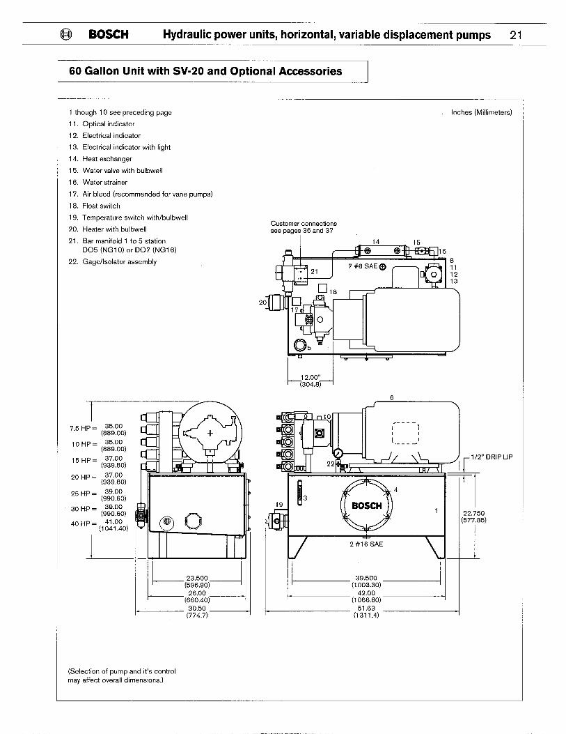
60 Gallon Unit with SV-20 and Optional Accessories
1 though 10 see preceding page Inches (Millimeters)
11. Optical indicator
12. Electrical indicator
13. Electrical indicator with light
14. Heat exchanger
15. Water valve with bulbwell
16. Water strainer
17. Air bleed (recommended for vane pumps)
18. Float switch
19. Temperature switch with/bulbwell
20. Heater with bulbwell
21. Bar manifold 1 to 5 station D05 (NG1 O) or D07 (NG16)
22. Gage/Isolator assembly
I 7.5 HP= ~::go;o)
10 HP = ~;:go;o)
15 HP= 37.00 (939.80)
20 HP = ~$:g~o)
25 HP = ~$joo;o)
30 HP = ~;~oojo)
40 HP= ~l;~fio)
L--
(Selection of pump and it’s control may affect overall dimensions.)
Customer connections see pages 36 and 37
2
“ DRIP
o 5)
LIP

22 Hydraulic power units, horizontal, variable displacement pumps BOSCH @
60 Gallon Unit with RKP-32
1, Tank
2. Tank drain connection
3, Oil level gage with thermometer
4. Clean out cover
5. Filler/Air breather
6. Motor/Pump group, shock mounted
7. Auxiliary return connection
8. Return filter, intank mounted
9. Relief valve, manifold mounted
10. Hydraulic pump
Inches (Millimeters)
r 1
‘ 0 ‘p = (::9°:0)
‘ 5 ‘p = (::9°:0)
20 ‘p = (s?:9°:0) 25 HP = ~:;oo;o) D
30 ‘p = (80°:0)
40 ‘p = (1 :1::0)
I
1A L,%!’,,)+ 26.00
(660.40)
27.25 (692.1 5)
6 -1
-. ---, 1 [ 1 1
( I -----
1 H 5 /
1 /2”
L
! \
II
4 3
‘h’? 1 22.750
(577.85)
I/ 2 #16 SAE
Mll
-.-.--1 L(,,o,’o,l] 42.00
(1066.80) 46.00
(1 168.40)
DRIP LIP
(Selection of pump and it’s control may affect overall dimensions.)

@ BOSCH Hydraulic power units, horizontal, variable displacement pumps 23
60 Gallon Unit with RKP-32 and Optional Accessories
1 though 10 see preceding page Inches (Millimeters)
11, Optical indicator
12, Electrical indicator
13. Electrical indicator with light
14. Heat exchanger
15, Water valve with bulbwell
16. Water strainer
17, Air bleed (recommended for vane pumps)
18, Float switch
19. Temperature switch with/bulbwell
20, Heater with bulbwell
21, Bar manifold 1 to 5 station D05 (NGI O) or D07 (NG16)
22. Gage/Isolator assembly
23, Adapter plate D07 (NG16) to D05 (NG1 O)
I kqggq (774.7)
(Selection of pump and it’s control may affect overall dimensions.)
Customer connections see pages 36 and 37
2
“ DRIP LIP
o 5)
+%2.+ (1 066.80)
24 Hydraulic power units, horizontal, variable displacement pumps BOSCH @
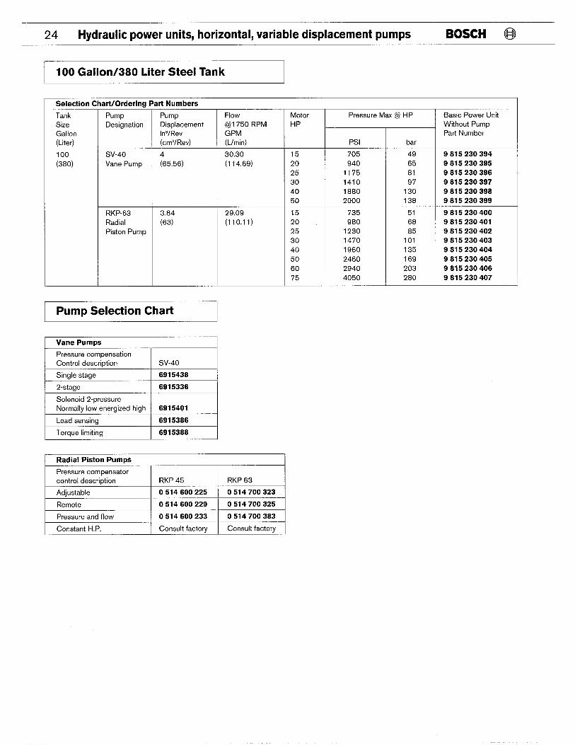
I 100 Gallon/380 Liter Steel Tank
Selection Chart/Orderin~ Part Numbers
Pump Designation
Tank Size Gallon (Liter)
100
(380)
Pump Displacement In’/Rev (cm’/Rev)
Flow (@I 750 RPN GPM (Llmin)
30.30 (1 14.69)
Motor HP
Pressure Max @ HP Basic Power Unit Without Pump Part Number
Psi
705 940
1175
1410 1880 2000
bar
49
65 81 97
130 138
15 20 25
30 40 50
9 815 230 394 9 815 230 395 9 815 230 396 9 815 230 397 9 815 230 398 9 815 230 399
SV-40 Vane Pump
4
(65.56)
RKP-63 Radial Piston Pump
3.84 (63)
29.09 (110.11)
15 20 25 30
40 50
60 75
735 980
1230 1470 1960
2460 2940 4050
51 68 85
101 135 169
203 280
9 815 230 400 9 815 230 401 9 815 230 402 9 815 230 403 9 815 230 404 9 815 230 405 9 815 230 406 9 815 230 407
Pump Selection Chart
I Vane Pumrx
I Pressure compensation Control description I SV-40
I Sinale staae I 6915438
I 2-staae I 6915336
I Solenoid 2-pressure I Normally low energized high 6915401
Load sensing 6915386
Torque limiting 6915388
I Radial Piston Pumrx I Pressure compensator control description RKP 45 RKP 63
Adjustable 0 514 600 225 0 514 700 323
I Remote I 0 514 600 229 I 0 514 700 325 I
Pressure and flow 0 514 600 233 0 514 700 383
Constant HP. Consult factory Consult factory

@ BOSCH Hydraulic power units, horizontal, variable displacement pumps 25
I Pump Control Manifold Selection Chart I
Manifold Type Reference Description Part Number
Flow control manifold See page 38. Load sense flow control 9 815 232 945
Pressure and flow control manifold See page 38. Combined pressure and flow control 9 815 232 946
Proportional control valves See page 38. See catalog NG6 and NG1 O propotiional Select from catalog.
Manifold Selection Chart
Manifold Type Reference See Page
See page 37.
Description ber Dura Bar
1 Valve Station 2 Valve Stations 3 Valve Stations 4 Valve Stations 5 Valve Stations
Bar manifold (D07/NG16)
9 815 232 923 9 815 232 924 9 815 232 925 9 815 232 926 9 815 232 927
9 815 232 928 9 815 232 929 9 815 232 930 9 815 232 931 9 815 232 932
Directional control valves See page 37,
See page 37,
See catalog directional Select from catalog. control valves
See catalog modular Select from catalog. control valves
Modular control valves
Accessory Selection Chart
Accessorv Reference DescritXion Model
RB5-03
Part Number
9 815 230 106 Filter clogging indicator See page 32, Optical (gage) Electrical (pressure switch) 250 VAC Electrical w/light (DIN plug w/light 24 Volt DC) Electrical w/light (DIN plug w/light 115 Volt AC)
Electrical w/light (DIN plug w/light 230 Volt AC)
9 815 230 107
9 815 230 108
9 815 230 109
9 815 230 110
Heat exchanaer See page 32.
See Daae 33.
Water to Oil 15 RB5-30 9 815 232 960
9 815 230 112 Water valve Modulating valve with bulbwell 3/4 RB5-45-E
Water strainer See page 33. RB5-43 9 815 232 948
Air bleed valve
Float switch
See page 34.
See page 35.
Recommended for vane pumps
Normally closed dry Normallv o~en drv
RB6-37
RB4-26
9 815 232 949
9 815 232 961 9 815 232 962
Temperature switch See page 36. Single contact Double contact
RB4-40B 9 815 232 952 9 815 232 953
Adapter See page 36.
See page 36.
See page 36.
D07 (NG16) to D05 (NG1 O) 9 815 232 963
Heater
Pressure gage
Heater w/bulbwell (Specify voltage.)
Gage isolator assembly
RB5-40
RB4-05
9 815 232 964
9 815 232 955
26 Hydraulic power units, horizontal, variable displacement pumps BOSCH @
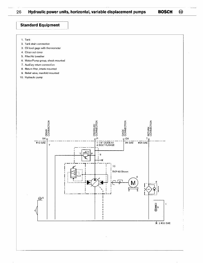
Standard Equipment
1, Tank
2. Tank drain connection
3, Oil level gage with thermometer
4, Clean out cover
5. Filler/Air breather
6, Motor/Pump group, shock mounted
7, Auxiliary return connection
8. Return filter, intank mounted
9. Relief valve, manifold mounted
10. Hydraulic pump
DR –
r
–P
T - GA
r
T– —.-— .— --— -- —-- —--— .- —-- —--— -- —.- -- —-- —--- -— --—
#12 SAE 1 114” CODE 61 #4 SAE 7 T
#24 SAE 4 BOLT FLANGE
[
5
4 I
I
I I I
I I I I
I I I I I I I 1,
1
~ 2 #20 SAE

@ BOSCH Hydraulic power units, horizontal, variable displacement pumps 27
I Optional Equipment I
1 though 10 see preceding page
11. Optical indicator
12. Electrical indicator
13. Electrical indicator with light
14. Heat exchanger
15. Water valve with buibwell
16, Water strainer
17, Air bleed (recommended for vane pumps)
18, Float switch
19, Temperature switch with/bulbwell
20, Heater with bulbwell
21. Bar manifold 1 to 5 station
22. Gage/Isolator assembly
I II bd I
I I I 1 m; I— --—--- --—’
i ‘~–] .- —- -—. - ---
ti: ?22 --- 14 -,
I II ~---- -T-+ LT--I
k 2 #20 SAE

28 Hydraulic power units, horizontal, variable displacement pumps BOSCH @
I 100 Gallon Unit with SV-40 I
1. Tank Inches (Millimeters)
2. Tank drain connection
3. Oil level gage with thermometer
4. Clean out cover
5. Filler/Air breather
6. Motor/Pump group, shock mounted
7. Auxiliary return connection
8. Return filter, intank mounted
9. Relief valve, manifold mounted
10. Hydraulic pump
15H
20 H
25 H
30 H
40 H
50 H
60 H
75 H
~!q;;41 27.50
30.00
31,25
7 #12 SAE
t--(4’:3Y5)-l
/ 6
\ 9 10
----- 1 ) 1 1 1 1 [ 1 I .- ..4
5 }, Id rp
1
Q
-r
3 4
BOSCH 24.75 (628.65)
1
2 #20 SAE
\ 1
I-----+; ’:O)4 57.00
(1 447.80)
LIP
(Selection of pump and it’s control may affect overall dimensions.)

@ BOSCH Hydraulic power units, horizontal, variable displacement pumps 29
100 Gallon Unit with SV-40 and Optional Accessories
1 though 10 see preceding page
11, Optical indicator
12, Electrical indicator
13, Electrical indicator with light
14. Heat exchanger
16.
17.
18.
19.
20.
21.
22.
23.
Water valve with bulbwell
Water strainer
Air bleed (recommended for vane pumps)
Float switch
Temperature switch with/bulbwell
Heater with bulbwell
Bar manifold 1 to 5 station
Gage/Isolator assembly
Adapter plate D07 (NG16) to D05 (NG1 O)
15HP
20 HP
25 HP
30 HP
40 HP
50 HP
60 HP
75 HP
Customer Connections see page 37
A l–
21
‘n
20 m q I 7
Q5
Inches (Millimeters)
9’2 6 . . /
9 1 o— ----- 1 1 1 1 r I 1 ,4 ---
22
I
! 3
Q
4
19 BOSCH 1
2 #20 SAE
I-----+::o)l 57.00
(1 ::4:0)
(161 2.9)
7 #12 SAE
~ 1 /2” DRIP LIP I
7 24.75
(62~.65)
I I
I
(Selection of pump and it’s control may affect overall dimensions.)

30 Hydraulic power units, horizontal, variable displacement pumps BOSCH @
100 Gallon Unit with RKP-63
1.
2.
3.
4.
5.
6.
7.
8.
9.
10.
Tank
Tank drain connection
Oil level gage with thermometer
Clean out cover
Filler/Air breather
Motor/Pump group, shock mounted
Auxiliary return connection
Return filter, intank mounted
Relief valve, manifold mounted
Hydraulic pump
Inches (Millimeters)
~ ‘31,25’ (793.75)
7#12 SAE
9
----- 1 ) 1 1 1 1 1
t ,.---
5 ~
m r 1 /2” DRIP LIP
I
II 3
Q
4
BOSCH 1
2 #20 SAE
L-----+:::O)J 57.00
(1 447.60)
‘5 65)
(Selection of pump and it’s control may affect overall dimensions.)
@ BOSCH Hydraulic power units, horizontal, variable displacement pumps 31
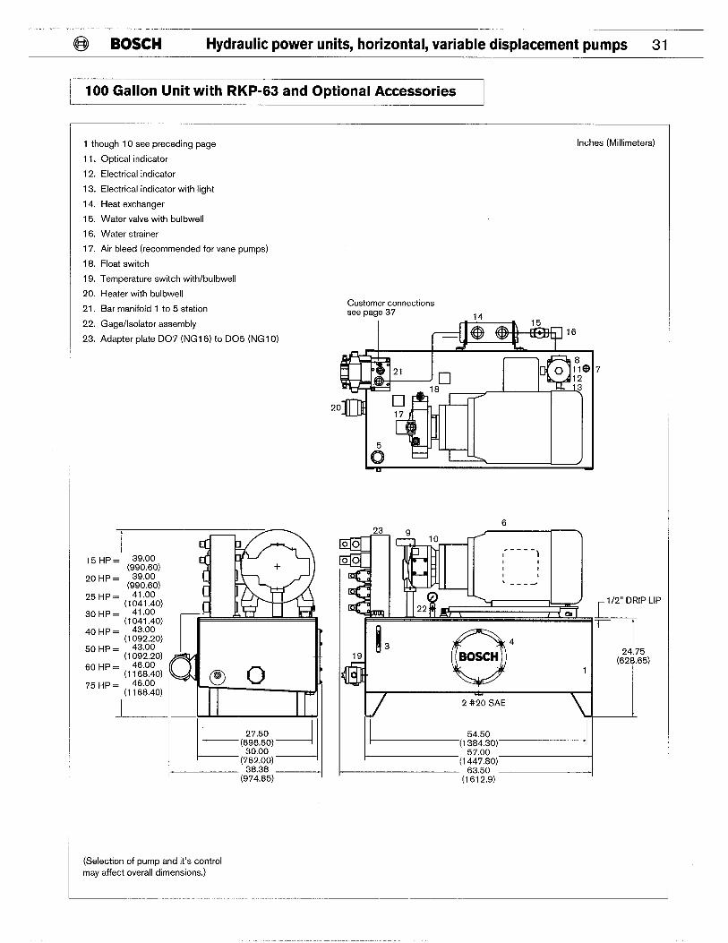
100 Gallon Unit with RKP-63 and Optional Accessories I
1 though 10 see preceding page
11.
12.
13.
14.
15.
16.
17.
18.
19.
20.
21.
22.
23.
Optical indicator
Electrical indicator
Electrical indicator with light
Heat exchanger
Water valve with bulbwell
Water strainer
Air bleed (recommended for vane pumps)
Float switch
Temperature switch withlbulbwell
Heater with bulbwell
Bar manifold 1 to 5 station
Gage/Isolator assembly
Adapter plate D07 (NG16) to D05 (NG1 O)
15
20
25
30
40
50
60
75
I 38.38 _l (974.85)
(Selection of pump and it’s control may affect overall dimensions.)
Inches (Millimeters)
Customer connections see page 37
—
6
1 /2” DRIP LIP
.
ml I 3 19 Q 4
BOSCH
2 #20 SAE
$$j!:d
1------5450 J
‘5 65)

32 Hydraulic power units, horizontal, variable displacement pumps BOSCH @
Filter Clogging Indicators
Optical Indicator Electrical Indicator (Set at 22 PSI) Optical/Electrical Indicator
3 – Color Gage Indicator Normally Open Part No,: 9 815 230 107 With 24 Volt Light DC, Part No. Part No,: 9 815 230 106 Switch Voltage MAX 250 AC/DC - 2A 9 815 230 108
With 115 Volt Light AC, Part No. 9 815 230 109 Wth 230 Volt Light DC, Part No. 9 815 230 110
~0157+
s- !2
0.47 HEX Cno
1/8 BSPT m, q 00 B
.1. .–
Pg 7 In N m
0.94 HEX K -+- 0.79 ~
w
-1 1:1/4B
Heat Exchanger
Water to Oil with Built in By-Pass Valve
Performance Characteristics
The curve shown is based on coolina water at 85° F (28° C) and oil leavin~ the cooler at 125° F (52° X). Curve perfor- mance is based on oil with a viscosit of
r 100 SUS (21 cST) at 100° F (38” C Pressure drop = 5PSI at 20 GPM.
Specifications
n Pressure Rating – Maximum working pressure: Oil side -550 PSI (38 bar) Water side -220 PSI (15 PSI) n Tem~erature Ratina – Maxim~m working temperature: 350° F(175°C) WOil to Water Ratio – 2:1
60
40
30
20
15
10 8 6
4
3
2
2 34579 15 20 30 40 50 70
OIL FLOW - GPM
‘@ ,. —- - 17 i_._:
Assembly Part No, Model Curve Tank Size Oil Connection Water Connection
9 815 232 947 10 RB5-30 1 35 Gal #12sAE 314 NPT
9 815 232 956 11 RB5-30 2 60 Gal #12sAE 314 NPT
9 815 232 960 15 RB5-30 3 100 Gal #24 SAE 1,50 NPT
@j BOSCH Hydraulic power units, horizontal, variable displacement pumps 33
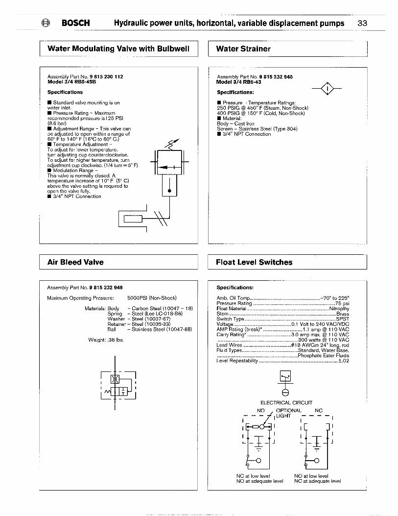
Water Modulating Valve with Bulbwell
Assembly Part No. 9 815 230 112 Model 3/4 RB5-45B
Specifications
n Standard valve mounting is on water inlet, 9 Pressure Rating – Maximum recommended pressure isl 25 PSI (8.6 bar) n Adjustment Range - This valve can be adjusted to open within a range of 60° F to 140° F (16°C to 60° C,) n Temperature Adjustment - To adjust for lower temperature. turn adjusting cup counterclockwise. To adjust for higher temperature, turn adjustment cup clockwise. (1/4 turn = 5° F) n Modulation Range – This valve is normally closed, A temperature increase of 10° F (5° C) above the valve setting is required to open the valve fully. n 3/4” NPT Connection
r=+ I
~ Air Bleed Valve I
Assembly Part No. 9815232949
Maximum Operating Pressure: 5000 PSI (Non-Shock)
Materials: Body - Carbon Steel (1 0047- 18) Spring - Steel (Lee LC-018-B6) Washer - Steel (1 0037-67) Retainer - Steel (1 0035-33) Ball - Stainless Steel (1 0047-88)
Weight: .38 Ibs.
+’
r)(- 1
i ---J
Water Strainer
Assembly Part No. 9 815 232 948 Model 3/4 RB5-43
Specifications:
n Pressure - Temperature Ratings: 250 PSIG @ 450” F (Steam, Non-Shock) 400 PSIG @ 150° F (Cold, Non-Shock) n Material: Body - Cast Iron Screen - Stainless Steel (Type 304) n 3/4” NPT Connection
--o-
1 Float Level Switches
Specifications:
Amb. Oil Temp . . . . . . . . . . . . . . . . . . . . . . . . . . . . . . . . . . . . . . . . . . . . . . . . . . . . . . . . . . ..7O0 to 225° Pressure Rating . . . . . . . . . . . . . . . . . . . . . . . . . . . . . . . . . . . . . . . . . . . . . . . . . . . . . . . . . . . . . . . . . . ...75 psi Float Material . . . . . . . . . . . . . . . . . . . . . . . . . . . . . . . . . . . . . . . . . . . . . . . . . . . . . . . . . . . . . . . . . . . .. Nitroplhy Stem . . . . . . . . . . . . . . . . . . . . . . . . . . . . . . . . . . . . . . . . . . . . . . . . . . . . . . . . . . . . . . . . . . . . . . . . . . . . . . . . . . . . . . . . .. Brass Switch Type . . . . . . . . . . . . . . . . . . . . . . . . . . . . . . . . . . . . . . . . . . . . . . . . . . . . . . . . . . . . . . . . . . . . . . . . . . . ..SPST Voltage . . . . . . . . . . . . . . . . . . . . . . . . . . . . . . . . . . . . . . . . . . . . . . ..O.l Volt to 240 VAC/VDC AMP Rating (break)* ..,.,.,., . . . . . . . . . . . . . . . . . . . . . ...1.1 amp @ 110 VAC Carry Rating* . . . . . . . . . . . . . . . . . . . . . . . . . . . . . . . . . . . ..3.O amp max. @ 110 VAC . . . . . . . . . . . . . . . . . . . . . . . . . . . . 300 watts @ 110 VAC
Lead Wires .,., . . . . . . . . . . . . . . . . . . . . . . . . . . . . . . . . . . ..#l 8 AWGm 24” long, red Fluid Types . . . . . . . . . . . . . . . . . . . . . . . . . . . . . . . . . . . . . . . . . . . . . .. Standard. Water Base,
. . . . . . . . . . . . . . . . . . . . . . . . . Phosphate Ester Fluids Level Repeatability . . . . . . . . . . . . . . . . . . . . . . . . . . . . . . . . . . . . . . . . . . . . . . . . . . . . . . . . . . . . . . . . . ..*.O2
T
.
ELECTRICAL CIRCUIT
NO
d
OPTIONAL NC ———
I ,LIGHT – – – –1
1
u’ ‘u’
I I
I
I L—— J
1 L—— J
T T
NC at low level NO at low level NO at adequate level NC at adequate level
34 Hydraulic power units, horizontal, variable displacement pumps BOSCH @
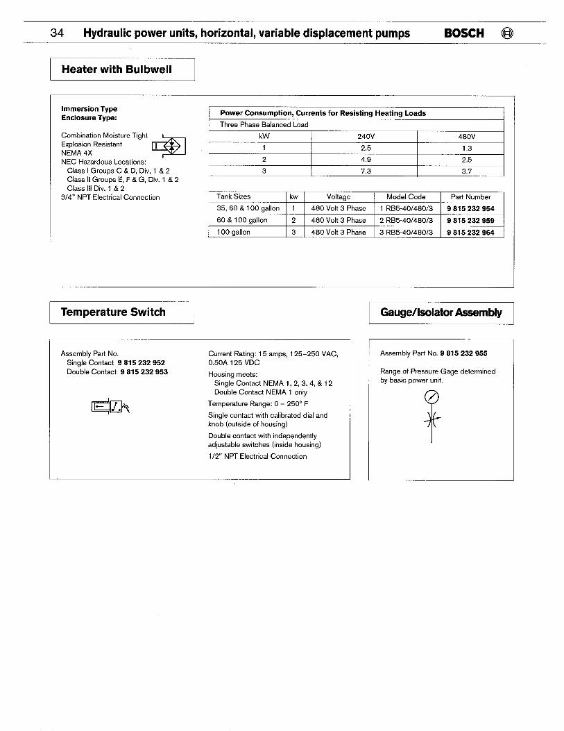
Heater with Bulbwell
Immersion Type Enclosure Type:
Combination Moisture Tight Explosion Resistant
* 1
NEMA 4X NEC Hazardous Locations: ‘
Class I Groups C & D, Div, 1 & 2 Class II Groups E, F &G, Div. 1 & 2 Class Ill Div. 1 & 2
3/4” NPT Electrical Connection
I Power Consumption, Currents for Resisting Heating Loads I Three Phase Balanced Load
kW 240V 480V
1 2.5 1,3
2 4,9 2,5
3 I 7,3 I 3.7 I
Tank Sizes I kw Voltage Model Code Part Number
35, 60 & 100 aallon I 1 480 Volt 3 Phase 1 RB5-40148013 9 815 232 954 9 815 232 959
100 gallon 3 480 Volt 3 Phase 3 RB5-40148013 9 815 232 964
I Temperature Switch I
Assembly Part No. Current Rating: 15 amps, 125-250 VAC, Single Contact 9815232952 0.50A 125 VDC
Double Contact 9815232953 Housing meets: Single Contact NEMA 1,2,3,4, & 12 Double Contact NEMA 1 only
f- Temperature Range: O – 250° F
Single contact with calibrated dial and knob (outside of housing)
Double contact with independently adjustable switches (inside housing)
1/2” NPT Electrical Connection
Gauge/Isolator Assembly
Assembly Part No. 9 815 232 955
Range of Pressure Gage determine by basic power unit.

@ BOSCH Hydraulic power units, horizontal, variable displacement pumps 35
Bar Manifold D03 (NG 6)
Inches (Millimeters)
IF 3,00
(76,20)
0.62
rl
0.62 (1 5.75) (1 5.75)
+
STATION 5 lb -@
A m @ 00 0 0
00 B
CAM& ~ ~rm CONNECTIONS
00
I !
I
T’ I I I
1.06 ~ (26.92)
Lj 3.51
(69,15)
STATION 4
STATION 3
STATION 2
STATION 1
-4 2.53 (64,26) k
n Any combination of single or double Note: When ordering valves as part or solenoid directional control valves may be a bar manifold, please specify the part used, Refer to Bosch catalog “Directional number(s) and the station to which they Control Valve D03 (NG6)” are, to be mounted. Stations are identified
as m above drawing. n All modular valves maybe used. Refer to Bosch catalog “Modular Valves D03 (NG 6)”
36 Hydraulic power units, horizontal, variable displacement pumps BOSCH @
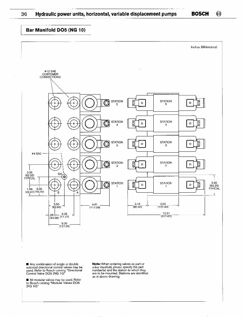
1 Bar Manifold D05 (NG 10) ~
Inches (Millimeters)
#12 SAE CUSTOMER
CONNECTIONS
\
#4sAE ~qlmsTA”ON STATION
2
STATION 1
t
2,50 ~ 4.61 (63,50) —1 —(1 1 7,09)
n Any combination of single or double solenoid directional control valves may be used. Refer to Bosch catalog “Directional Control Valve D05 (NG 10)”
m o STATION 4
m
o
/ I I \ m o STATION 3
m
o
m 0 STATION 2
a
0
STATION 1
I
I I
I I I
Note: When ordering valves as part or a bar manifold, please specify the part number(s) and the station to which they are to be mounted. Stations are identified as in above drawing.
7 3.25
(82.55) TYPICAL
-.-1
n All modular valves may be used. Refer to Bosch catalog “Modular Valves D05 (NG 10)”
@ BOSCH Hydraulic power units, horizontal, variable displacement pumps 37
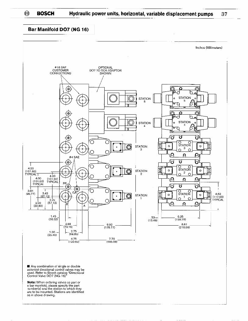
Bar Manifold D07 (NG 16)
Inches (Millimeters)
#16sAE OPTIONAL CUSTOMER DO? TO D05 ADAPTOR
CONNECTIONS SHOWN
STATION 5
“ WI I I
B f I r { I
I
I #4 SAE l—
I STATION
13
STATION
12
(
1.43 I I I Ill I
[ STATION
1
. r,
I 4.63
(1 17.60) TYPICAL
II t? 95 I I (36.32~
~J
,*
2.88 (73,15)
6.92 (1 75.77)
I “’7--=;;7= 1.00 — ~(:g7:5)_l
(25.40) ~ >(,;(:5)_l 7.70 I
(1 95.58)
H Any combination of single or double solenoid directional control valves may be used. Refer to Bosch catalog “Directional Control Valve D07 (NG 16)”
Note: When ordering valves as part or a bar manifold, please specify the part number(s) and the station to which they are to be mounted. Stations are identified as in above drawing.
38 Hydraulic power units, horizontal, variable displacement pumps BOSCH @
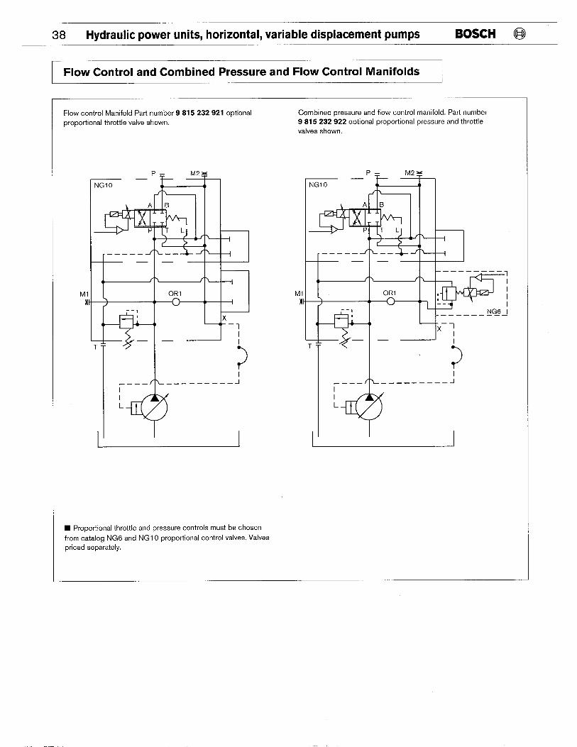
I Flow Control and Combined Pressure and Flow Control Manifolds 1
Flow control Manifold Part number 9 815 232 921 optional proportional throttle valve shown.
, ~------ -1
A —— J- ~ +
4 ) f > f > I
Ml ORI MI >
w I -- I
I x ( I ‘–7
J. T
l’. ~
I
?
-.—— ————— ———— J
Combined pressure and flow control manifold. Part number 9 815 232 922 optional proportional pressure and throttle
valves shown.
Ml n
‘4 -——— ——— ——— ——— J
L
1’ I
n Proportional throttle and pressure controls must be chosen
from catalog NG6 and NG1 O proportional control valves. Valves priced separately.

ROBERT BOSCH FLUID POWER CORPORATIONP.O. BOX 2025RACINE, WISCONSIN 53401-2025 U.S.A.Phone (414)554-7100, Fax (414)554-7117
PRINTED IN U.S.A.
9 535 233 103HPUS AKY 004/4 US (2.96)