
2 FCM - Automazioni per cancelli elettrici, scorrevoli, a ... · colori: marrone-rosso, blu-grigio...
8
GUIDA ALL’INSTALLAZIONE INSTALLATION GUIDE INSTALLATIONSANLEITUNG NOTICE D’INSTALLATION GUÍA PARA LA INSTALACIÓN FCM Finecorsa magnetici (Serie T-ONE) Magnetic limit switches (T-ONE Series) Magnetische Endschalter (Serie T-ONE) Fin de course magnétiques (Série T-ONE) Final de recorrido magnéticos (Serie T-ONE) Via Enrico Fermi, 43 - 36066 Sandrigo (VI) Italia Tel +39 0444 750190 - Fax +39 0444 750376 [email protected] - www.tauitalia.com IT - Istruzioni originali D-MNL0FCM 17-04-2012 - Rev.03
Transcript of 2 FCM - Automazioni per cancelli elettrici, scorrevoli, a ... · colori: marrone-rosso, blu-grigio...
1FCM
GUIDA ALL’INSTALLAZIONEINSTALLATION GUIDE
INSTALLATIONSANLEITUNGNOTICE D’INSTALLATION
GUÍA PARA LA INSTALACIÓN
FCMFinecorsa magnetici (Serie T-ONE) Magnetic limit switches (T-ONE Series)Magnetische Endschalter (Serie T-ONE)
Fin de course magnétiques (Série T-ONE)Final de recorrido magnéticos (Serie T-ONE)
Via Enrico Fermi, 43 - 36066 Sandrigo (VI) ItaliaTel +39 0444 750190 - Fax +39 0444 750376
[email protected] - www.tauitalia.com
IT - Istruzioni originali
D-M
NL0
FC
M 1
7-0
4-2
012 -
Rev
.03
2 FCM
FINECORSA MAGNETICINOTA: per un corretto funzionamento maneggiare con cura il sensore (contiene due fiale in vetro). Evitare urti o cadute durante l’installazione!!L’art. P-400FCM è composto da due magneti da applicare alla cremagliera ed un sensore da installare sul motoriduttore. Durante il movimento, il cancello che porta i magneti montati sulla cremagliera si avvicina al sensore installato sul motoriduttore attivandolo, comandando così l’arresto della chiusura.In fig. 1 sono riportate le distanze di attivazione del sensore in apertura ed in chiusura. I magneti devono essere installati ad una distanza dal bordo della chiusura (X fig. 2) tenendo conto dell’inerzia del cancello. Consigliamo di provare i magneti sulla cremagliera prima di fissarli in maniera definitiva (grazie all’anima in metallo i magneti restano ben fermi) al fine di trovare la posizione che permetta un funzionamento ottimale.Il magnete con polarità Nord viene utilizzato come finecorsa in apertura (OLS), quello con polarità Sud come finecorsa in chiusura (CLS).Corrispondenza coloriAll’atto della sostituzione dei microinterruttori elettrici con il sensore magnetico, rispettare la seguente corrispondenza di colori: marrone-rosso, blu-grigio e nero-arancione.IMPORTANTE: con i finecorsa magnetici installati, è necessario attivare la frenata (vedi istruzioni scheda di co-mando, sez. dip-switches).
MAGNETIC LIMIT SWITCHESNOTE: to ensure correct operation, handle the sensor with care (it contains two glass phials). Avoid impact or dropping during installation!Art. P-400FCM comprises two magnets for application on the rack and a sensor for installation on the gearmotor. During movement, the gate mounting the magnets fitted on the rack approaches the sensor installed on the gearmotor, and acti-vates this sensor, consequently stopping closure.Fig. 1 shows the activation distances of the sensor on opening and closing. The magnets must be installed at a distance from the closing edge (X, fig. 2) taking gate inertia into account. We recommend testing the magnets on the rack before fixing them permanently (the magnets remain firmly in place thanks to the metal core) in order to find the correct position for optimal operation.The magnet with North polarity is used as an opening limit switch (OLS), and the magnet with South polarity is used as a closing limit switch (CLS).Colour codingWhen replacing the electrical microswitches with the magnetic sensor, observe the following colour coding: brown-red, blue-grey and black-orange.IMPORTANT: It is necessary to activate the brake function (see controller’s manual, “DIP Switches” section) when magnetic limit switches are installed.
MAGNETISCHE ENDSCHALTERANMERKUNG: Für einen korrekten Betrieb den Sensor mit Sorgfalt behandeln (er enthält zwei Glasampullen). Während der Installation Stöße oder ein Herunterfallen vermeiden!!Der Art. P-400FCM besteht aus zwei Magneten, die an der Zahnstange anzubringen sind und einem Sensor, der am Tor-öffner installiert werden muss. Während der Bewegung nähert sich das Tor, das die in der Zahnstange montierten Magnete aufweist, dem im Toröffner installierten Sensor und aktiviert ihn, wodurch der Stopp der Schließbewegung gesteuert wird.In der Abb. 1 sind die Aktivierungsdistanzen des Sensors während des Öffnens und Schließens aufgeführt. Die Magnete müssen auf einer Distanz ab der Schließkante installiert werden (X Abb. 2), wobei die Schwungkraft des Tors in Betracht gezogen werden muss. Wir empfehlen, die Magnete in der Zahnstange zu prüfen, bevor sie definitiv befestigt werden (dank des Metallkerns halten die Magnete gut), um die Position zu finden, die eine optimale Funktionstüchtigkeit ermöglicht.Der Magnet mit nördlicher Polarität wird als Öffnungsendschalter (OLS), der mit südlicher Polarität als Schließendschalter (CLS) verwendet.Übereinstimmung der FarbenBeim Austausch der elektrischen Mikroschalter mit dem magnetischen Sensor müssen die folgenden Farbkombinationen eingehalten werden: Braun-rot, blau-grau und schwarz-orange.WICHTIG: Sind die magnetischen Endschalter installiert, muss die Bremsfunktion (siehe Platine-Betriebsanlei-tung, „DIP Switches“) aktiviert werden.
FINS DE COURSE MAGNÉTIQUESNOTE : pour un fonctionnement correct, manipuler avec soin le capteur (il contient deux ampoules en verre). Éviter les chocs ou les chutes durant l’installation !!L’art. P-400FCM est composé de deux aimants à appliquer à la crémaillère et d’un capteur à installer sur l’opérateur. Durant le mouvement, le portail qui porte les aimants montés sur la crémaillère s’approche du capteur installé sur l’opérateur en l’activant et en commandant ainsi l’arrêt de la fermeture.La fig. 1 indique les distances d’activation du capteur en ouverture et en fermeture. Les aimants doivent être installés à une distance du bord de la fermeture (X fig. 2) tenant compte de l’inertie du portail. Nous conseillons d’essayer les aimants sur la crémaillère avant de les fixer de manière définitive (grâce à l’âme en métal les aimants restent bien en place) afin de trouver la position qui permet un fonctionnement optimal.L’aimant avec polarité Nord est utilisé comme fin de course en ouverture (OLS), celui avec polarité Sud comme fin de course en fermeture (CLS).Correspondance des couleursAu moment du remplacement des microinterrupteurs électriques par le capteur magnétique, respecter la correspondance de couleurs suivante : marron-rouge, bleu-gris et noir-orange.IMPORTANT: avec les fins de courses magnétiques installées, il est nécessaire d’activer le freinage (voir les no-tices techniques de la centrale de commande, au paragraphe concernant les dip-switches).
Italiano
English
Deutsch
Français
3FCM
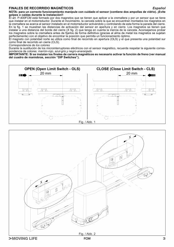
OPEN (Open Limit Switch - OLS) CLOSE (Close Limit Switch - CLS)20 mm 20 mm
X
X
Fig. / Abb. 1
Fig. / Abb. 2
FINALES DE RECORRIDO MAGNÉTICOSNOTA: para un correcto funcionamiento manipule con cuidado el sensor (contiene dos ampollas de vidrio). ¡Evite golpes o caídas durante la instalación!!El art. P-400FCM está formado por dos magnetos que se tienen que aplicar a la cremallera y por un sensor que se tiene que instalar en el motorreductor. Durante el movimiento, la cancela sobre la que se encuentran montados los magnetos en la cremallera se acerca al sensor instalado en el motorreductor activándolo y controlando de esta forma la parada del cierre.En la fig. 1 se muestran las distancias de activación del sensor en apertura y en cierre. Los magnetos se tienen que instalar a una distancia del borde del cierre (X fig. 2) que tenga en cuenta la inercia de la cancela. Aconsejamos probar los magnetos sobre la cremallera antes de fijarlos de forma definitiva (gracias al alma de metal los magnetos se sujetan perfectamente) con el objetivo de encontrar la posición que permita un funcionamiento óptimo.El magneto con polaridad norte se utiliza como final de recorrido en apertura (OLS) y el que presenta una polaridad sur como final de recorrido en cierre (CLS).Correspondencia de los coloresDurante la sustitución de los microinterruptores eléctricos con el sensor magnético, recuerde respetar la siguiente corres-pondencia de colores: marrón-rojo, azul-gris y negro-anaranjado.IMPORTANTE: Si se instalan los finales de carrera magnéticos es necesario activar la función de freno (ver manual del cuadro de maniobras, sección “DIP Switches”).
Español
4 FCM
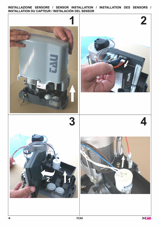
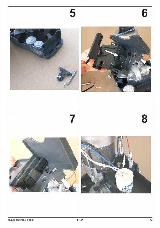
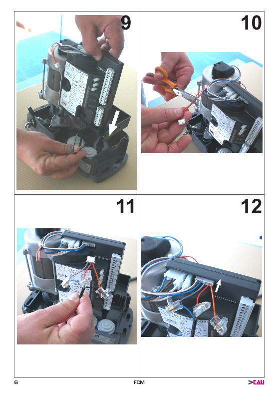
INSTALLAZIONE SENSORE / SENSOR INSTALLATION / INSTALLATION DES SENSORS / INSTALLATION DU CAPTEUR / INSTALACIÓN DEL SENSOR
1 2
3 4
5FCM
5
7
6
8
6 FCM
9 10
11 12
7FCM
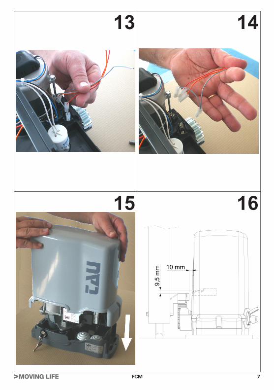
13
15
14
16
10 mm
9,5
mm