2 Building Blocks of IEC 61131-3 - Springer
46
2 Building Blocks of IEC 61131-3 This chapter explains the meaning and usage of the main language elements of the IEC 61131-3 standard. These are illustrated by several examples from real life, with each example building upon the previous one. The reader is introduced to the terms and ways of thinking of IEC 61131-3. The basic ideas and concepts are explained clearly and comprehensively without dis- cussing the formal language definitions of the standard itself [IEC 61131-3]. The first section of this chapter gives a compact introduction to the conceptual range of the standard by means of an example containing the most important language elements and providing an overview of the methodology of PLC pro- gramming with IEC 61131-3. The term “POU” (Program Organisation Unit) is explained in detail because it is fundamental for a complete understanding of the new language concepts. As the programming language Instruction List (IL) is already well known to most PLC programmers, it has been chosen as the basis for the examples in this chapter. IL is widespread on the European PLC market and its simple syntax makes it easy to comprehend. The programming language IL itself is explained in Section 4.1. 2.1 Introduction to the New Standard IEC 61131-3 not only describes the PLC programming languages themselves, but also offers comprehensive concepts and guidelines for creating PLC projects. The purpose of this section is to give a short summary of the important terms of the standard without going into details. These terms are illustrated by a simple example. More detailed information will be found in the subsequent sections and chapters. K.-H. John, M. Tiegelkamp, IEC 61131-3: Programming Industrial Automation Systems, 2nd ed., DOI 10.1007/978-3-642-12015-2_2, © Springer-Verlag Berlin Heidelberg 2010
Transcript of 2 Building Blocks of IEC 61131-3 - Springer
2 Building Blocks of IEC 61131-3
This chapter explains the meaning and usage of the main language elements of the IEC 61131-3 standard. These are illustrated by several examples from real life,with each example building upon the previous one.
The reader is introduced to the terms and ways of thinking of IEC 61131-3. Thebasic ideas and concepts are explained clearly and comprehensively without dis-cussing the formal language definitions of the standard itself [IEC 61131-3].
The first section of this chapter gives a compact introduction to the conceptualrange of the standard by means of an example containing the most importantlanguage elements and providing an overview of the methodology of PLC pro-gramming with IEC 61131-3.
The term “POU” (Program Organisation Unit) is explained in detail because it is fundamental for a complete understanding of the new language concepts.
As the programming language Instruction List (IL) is already well known to mostPLC programmers, it has been chosen as the basis for the examples in this chapter. IL is widespread on the European PLC market and its simple syntax makes it easyto comprehend.
The programming language IL itself is explained in Section 4.1.
2.1 Introduction to the New Standard
IEC 61131-3 not only describes the PLC programming languages themselves, butalso offers comprehensive concepts and guidelines for creating PLC projects.
The purpose of this section is to give a short summary of the important terms ofthe standard without going into details. These terms are illustrated by a simpleexample. More detailed information will be found in the subsequent sections andchapters.
K.-H. John, M. Tiegelkamp, IEC 61131-3: Programming Industrial Automation Systems, 2nd ed., DOI 10.1007/978-3-642-12015-2_2, © Springer-Verlag Berlin Heidelberg 2010

22 2 Building Blocks of IEC 61131-3
2.1.1 Structure of the building blocks
POUs correspond to the Blocks in previous (conventional) programming systems.POUs can call each other with or without parameters. As the name implies, POUsare the smallest independent software units of a user program.
There are three types of POUs: Function (FUN), Function block (FB) andProgram (PROG), in ascending order of functionality. The main differencebetween functions and function blocks is that functions always produce the sameresult (function value) when called with the same input parameters, i.e. they haveno “memory”. Function blocks have their own data record and can therefore“remember” status information (instantiation). Programs (PROG) represent the“top” of a PLC user program and have the ability to access the I/Os of the PLC and to make them accessible to other POUs.
IEC 61131-3 predefines the calling interface and the behaviour of frequentlyneeded standard functions (std. FUN) such as arithmetic or comparison functions, as well as standard function blocks (std. FB), such as timers or counters.
Declaration of variablesThe IEC 61131-3 standard uses variables to store and process information.Variables correspond to (global) flags or bit memories in conventional PLCsystems. However, their storage locations no longer need to be defined manuallyby the user (as absolute or global addresses), but they are managed automaticallyby the programming system and each possess a fixed data type.
IEC 61131-3 specifies several data types (Bool, Byte, Integer, ...). These differ,for example, in the number of bits or the use of signs. It is also possible for theuser to define new data types: user-defined data types such as structures andarrays.
Variables can also be assigned to a certain I/O address and can be battery-backed against power failure.
Variables have different forms. They can be defined (declared) outside a POU and used program-wide, they can be declared as interface parameters of a POU, or they can have a local meaning for a POU. For declaration purposes they are thereforedivided into different variable types. All variables used by a POU have to bedeclared in the declaration part of the POU.
The declaration part of a POU can be written in textual form independently ofthe programming language used. Parts of the declaration (input and outputparameters of the POU) can also be represented graphically.

2.1 Introduction to the New Standard 23
VAR_INPUT (* Input variable *)ValidFlag : BOOL; (* Binary value *)
END_VARVAR_OUTPUT (* Output variable *)
RevPM : REAL; (* Floating-point value *)END_VARVAR RETAIN (* Local variable, battery-backed *)
MotorNr : INT; (* Signed integer *)MotorName : STRING [10]; (* String of length 10 *)EmStop AT %IX2.0 : BOOL; (* Input bit 2.0 of I/O *)
END_VAR
Example 2.1. Example of typical variable declarations of a POU
Example 2.1 shows the variable declaration part of a POU. A signed integervariable (16 bits incl. sign) with name MotorNr and a text of length 10 with nameMotorName are declared. The binary variable EmStop (emergency stop) isassigned to the I/O signal input 2.0 (using the keyword “AT”). These threevariables are known only within the corresponding POU, i.e. they are “local”.They can only be read and altered by this POU. During a power failure they retain their value, as is indicated by the qualifier “RETAIN”. The value for input variable ValidFlag will be set by the calling POU and have the Boolean values TRUE orFALSE. The output parameter returned by the POU in this example is the floating-point value RevPM.
The Boolean values TRUE and FALSE can also be indicated by “1” and “0”.
Code part of a POUThe code part, or instruction part, follows the declaration part and contains theinstructions to be processed by the PLC.
A POU is programmed using either the textual programming languagesInstruction List (IL) and Structured Text (ST) or the graphical languages LadderDiagram (LD) and Function Block Diagram (FBD). IL is a programming language closer to machine code, whereas ST is a high-level language. LD is suitable forBoolean (binary) logic operations. FBD can be used for programming bothBoolean (binary) and arithmetic operations in graphical representation.
24 2 Building Blocks of IEC 61131-3
%IX23.5 Motor
ButtonN
S1
R
SRFlipFlop
Q1 VarOut
VarIn
EmStop
Ladder Diagram
>=%IW3
%MW3
Function Block Diagram
Instruction List Structured Text
LDORNANDNS
S
%IX23.5ButtonEmStopMotor
FlipFlop (R := VarIn );S1 := (%IW3 >= %MW3),
VarOut := FlipFlop.Q1;
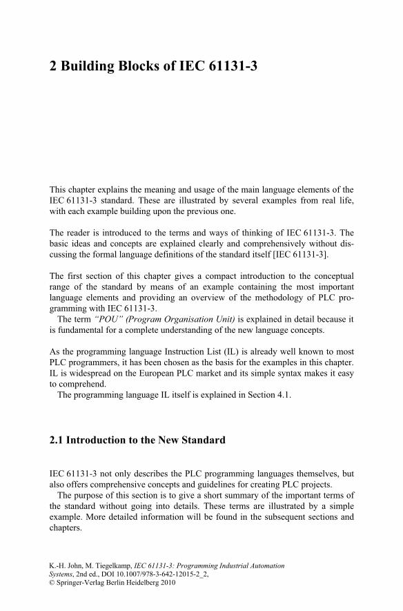
Figure 2.1. Simple examples of the programming languages LD, FBD, IL and ST. The examples in LD and IL are equivalent to one another, as are those in FBD and ST.
Additionally, the description language Sequential Function Chart (SFC) can beused to describe the structure of a PLC program by displaying its sequential andparallel execution. The various subdivisions of the SFC program (steps andtransitions) can be programmed independently using any of the IEC 61131-3programming languages.
2.1 Introduction to the New Standard 25
Sequential Function Chart
t3
t4
t5
S0
S1
S3
S2
&
t1
t2
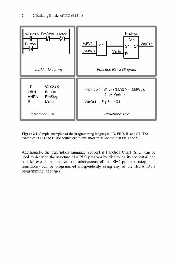
Figure 2.2. Schematic example of structuring using SFC. The execution parts of the steps (S0 to S3) and the transitions (t1 to t5) can be programmed using any other programming language.
Figure 2.2 shows an SFC example: Steps S0, S1 and S3 are processed sequentially.S2 can be executed alternatively to S1. Transitions t1 to t5 are the conditionswhich must be fulfilled before proceeding from one step to the next.
2.1.2 Introductory example written in IL
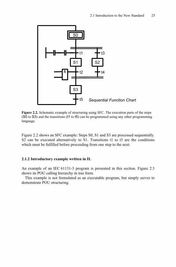
An example of an IEC 61131-3 program is presented in this section. Figure 2.3shows its POU calling hierarchy in tree form.
This example is not formulated as an executable program, but simply serves todemonstrate POU structuring.
26 2 Building Blocks of IEC 61131-3
MotorControlprogram
MotAccelfunction block
MotStartfunction
LOGstandard function
MotBrakefunction block
Figure 2.3. Calling hierarchy of POUs in the example
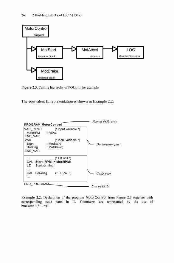
The equivalent IL representation is shown in Example 2.2.
PROGRAM MotorControlVAR_INPUT (* inpu t variable *)
MaxRPM : REAL;END_VARVAR (* local variable *)
S tart : MotStart;Braking : MotBrake;
END_VAR
... (* FB call *)CAL Start (RPM := MaxRPM)LD Start.running...CAL Braking (* FB call *)...
END_PROGRAM
Named POU type
End of POU
Declaration part
Code part
Example 2.2. Declaration of the program MotorControl from Figure 2.3 together withcorresponding code parts in IL. Comments are represented by the use ofbrackets: “(* ... *)”.
2.1 Introduction to the New Standard 27
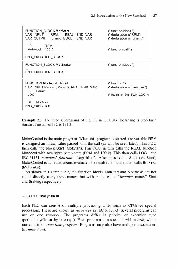
FUNCTION_BLOC K MotStart (* function block *)VAR_INPUT RPM: REAL; END_VAR (* declaration of RPM*)VAR_OUTPUT running: BOOL; END_VAR (* declaration of running*)
...LD RPMMotAccel 100.0 (* function call *)...
END_FUNCTION_BLOCK
FUNCTION_BLOC K MotBrake (* function block *)...END_FUNCTION_BLOCK
FUNCTION MotAccel : REAL (* function *)VAR_INPUT Param1, Param2: REAL; END_VAR (* declaration of variables*)
LD Param2LOG (* invoc. of Std. FUN LOG *)...ST MotAccel
END_FUNCTION
Example 2.3. The three subprograms of Fig. 2.3 in IL. LOG (logarithm) is predefinedstandard function of IEC 61131-3.
MotorControl is the main program. When this program is started, the variable RPMis assigned an initial value passed with the call (as will be seen later). This POUthen calls the block Start (MotStart). This POU in turn calls the REAL functionMotAccel with two input parameters (RPM and 100.0). This then calls LOG – theIEC 61131 standard function “Logarithm”. After processing Start (MotStart),MotorControl is activated again, evaluates the result running and then calls Braking,(MotBrake).
As shown in Example 2.2, the function blocks MotStart and MotBrake are notcalled directly using these names, but with the so-called “instance names” Startand Braking respectively.
2.1.3 PLC assignment
Each PLC can consist of multiple processing units, such as CPUs or specialprocessors. These are known as resources in IEC 61131-3. Several programs canrun on one resource. The programs differ in priority or execution type(periodic/cyclic or by interrupt). Each program is associated with a task, whichmakes it into a run-time program. Programs may also have multiple associations(instantiation).

28 2 Building Blocks of IEC 61131-3
Before the program described in Examples 2.2 and 2.3 can be loaded into the PLC, more information is required to ensure that the associated task has the desiredproperties:
- On which PLC type and which resource is the program to run?- How is the program to be executed and what priority should it have?- Do variables need to be assigned to physical PLC addresses?- Are there global or external variable references to other programs to be
declared?
This information is stored as the configuration, as illustrated textually in Example 2.4 and graphically in Figure 2.4.
CONFIGURATION MotorConVAR_GLOBAL Trigger AT %IX2.3 : BOOL; END_VARRESOURCE Res_1 ON CPU001
TASK T_1 (INTERVAL := t#80ms, PRIORITY := 4);PROGRAM MotR WITH T_1 : MotorControl (MaxRPM := 12000);
END_RESOURCERESOURCE Res_2 ON CPU002
TASK T_2 (SINGLE := Trigger, PRIORITY := 1);PROGRAM MotP WITH T_2 : MotorProg (...);
END_RESOURCEEND_CONFIGURATION
Example 2.4. Assignment of the programs in Example 2.3 to tasks and resources in a“configuration”

2.1 Introduction to the New Standard 29
Res_1
MotStart MotBrake
MotAccel LOG
Program MotorProg
...
cyclic
high priorityinterrupt
low priority
CONFIGURATION
Allocation of hardware addressesglobal & access variables
...
Task: Task:
CPU001Res_2
CPU002
MotorCon
Program MotorControl
cyclic
high priorityinterrupt
low priority
Figure 2.4. Assignment of the programs of a motor control system MotorCon to tasks in the PLC “configuration”. The resources (processors) of the PLC system execute the resulting run-time programs.
Figure 2.4 continues Example 2.3. Program MotorControl runs together with itsFUNs and FBs on resource CPU001. The associated task specifies thatMotorControl should execute cyclically with low priority. Program MotorProg runs here on CPU002, but it could also be executed on CPU001 if this CPU supportsmultitasking.
The configuration is also used for assigning variables to I/Os and for managingglobal and communication variables. This is also possible within a PROGRAM.
A PLC project consists of POUs that are either shipped by the PLC manufactureror created by the user. User programs can be used to build up libraries of testedPOUs that can be used again in new projects. IEC 61131-3 supports this aspect of software re-use by stipulating that functions and function blocks have to remain“universal”, i.e. hardware-independent, as far as possible.
After this short summary, the properties and special features of POUs will now be explained in greater detail in the following sections.
30 2 Building Blocks of IEC 61131-3
2.2 The Program Organisation Unit (POU)
IEC 61131-3 calls the blocks from which programs and projects are built ProgramOrganisation Units (POUs). POUs correspond to the program blocks, organisationblocks, sequence blocks and function blocks of the conventional PLC program-ming world.
One very important goal of the standard is to restrict the variety and oftenimplicit meanings of block types and to unify and simplify their usage.
DBDatablock
OBOrganisationblock PB
Programblock
SBSequenceblock
Block types used in DIN 19239 POUs in IEC 61131-3
PROGRAM
Main program
FBFunctionblock
FUNCTION
Function
FUNCTION
Functionblock
BLOCK
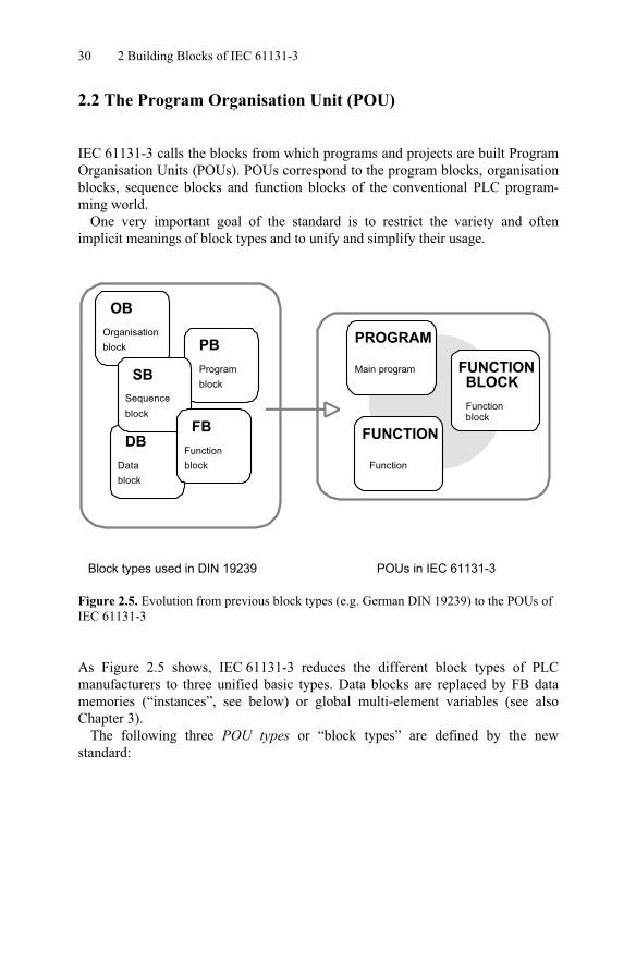
Figure 2.5. Evolution from previous block types (e.g. German DIN 19239) to the POUs of IEC 61131-3
As Figure 2.5 shows, IEC 61131-3 reduces the different block types of PLCmanufacturers to three unified basic types. Data blocks are replaced by FB datamemories (“instances”, see below) or global multi-element variables (see alsoChapter 3).
The following three POU types or “block types” are defined by the newstandard:
2.2 The Program Organisation Unit (POU) 31
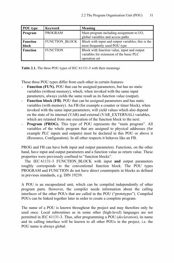
POU type Keyword MeaningProgram PROGRAM Main program including assignment to I/O,
global variables and access pathsFunctionblock
FUNCTION_BLOCK Block with input and output variables; this is the most frequently used POU type
Function FUNCTION Block with function value, input and outputvariables for extension of the basic PLC operation set
Table 2.1. The three POU types of IEC 61131-3 with their meanings
These three POU types differ from each other in certain features:- Function (FUN). POU that can be assigned parameters, but has no static
variables (without memory), which, when invoked with the same input parameters, always yields the same result as its function value (output).
- Function block (FB). POU that can be assigned parameters and has static variables (with memory). An FB (for example a counter or timer block), when invoked with the same input parameters, will yield values which also depend on the state of its internal (VAR) and external (VAR_EXTERNAL) variables, which are retained from one execution of the function block to the next.
- Program (PROG). This type of POU represents the “main program”. Allvariables of the whole program that are assigned to physical addresses (forexample PLC inputs and outputs) must be declared in this POU or above it(Resource, Configuration). In all other respects it behaves like an FB.
PROG and FB can have both input and output parameters. Functions, on the other hand, have input and output parameters and a function value as return value. These properties were previously confined to “function blocks”.
The IEC 61131-3 FUNCTION_BLOCK with input and output parametersroughly corresponds to the conventional function block. The POU typesPROGRAM and FUNCTION do not have direct counterparts in blocks as defined in previous standards, e.g. DIN 19239.
A POU is an encapsulated unit, which can be compiled independently of otherprogram parts. However, the compiler needs information about the callinginterfaces of the other POUs that are called in the POU (“prototypes”). CompiledPOUs can be linked together later in order to create a complete program.
The name of a POU is known throughout the project and may therefore only beused once. Local subroutines as in some other (high-level) languages are notpermitted in IEC 61131-3. Thus, after programming a POU (declaration), its name and its calling interface will be known to all other POUs in the project, i.e. thePOU name is always global.
32 2 Building Blocks of IEC 61131-3
This independence of POUs facilitates extensive modularisation of automationtasks as well as the re-use of already implemented and tested software units.
In the following sections the common properties of the different types of POUswill first be discussed. The POU types will then be characterised, the callingrelationships and other properties will be described, and finally the different typeswill be summarised and compared.
2.3 Elements of a POU
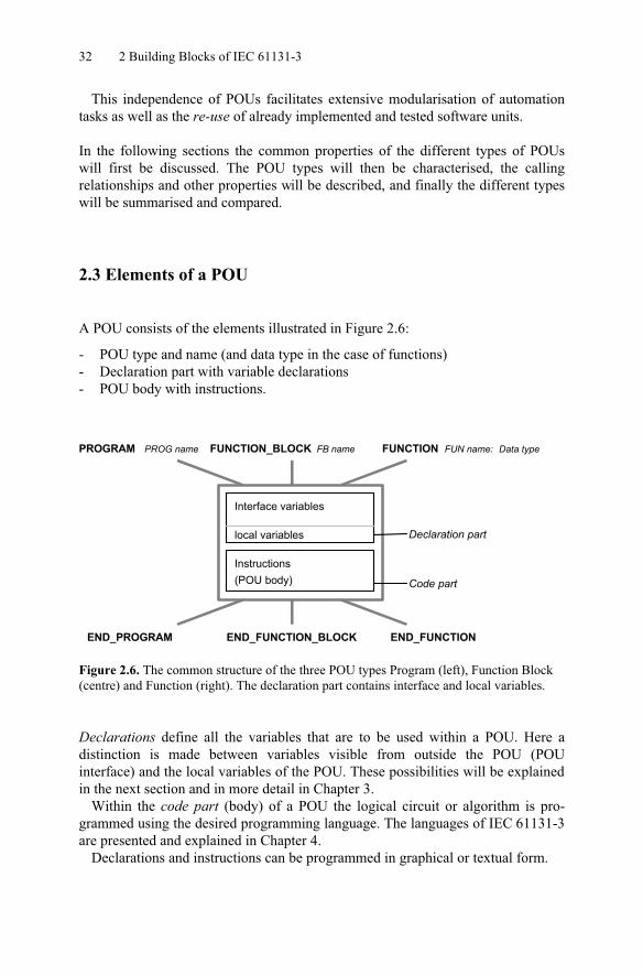
A POU consists of the elements illustrated in Figure 2.6:
- POU type and name (and data type in the case of functions)- Declaration part with variable declarations- POU body with instructions.
PROGRAM PROG name
END_PROGRAM
FUNCTION_BLOCK FB name
END_FUNCTION_BLOCK
Instructions(POU body)
FUNCTION FUN name:
END_FUNCTION
Data type
Interface variables
Declaration part
Code part
local variables
Figure 2.6. The common structure of the three POU types Program (left), Function Block (centre) and Function (right). The declaration part contains interface and local variables.
Declarations define all the variables that are to be used within a POU. Here adistinction is made between variables visible from outside the POU (POUinterface) and the local variables of the POU. These possibilities will be explained in the next section and in more detail in Chapter 3.
Within the code part (body) of a POU the logical circuit or algorithm is pro-grammed using the desired programming language. The languages of IEC 61131-3are presented and explained in Chapter 4.
Declarations and instructions can be programmed in graphical or textual form.
2.3 Elements of a POU 33
2.3.1 Example
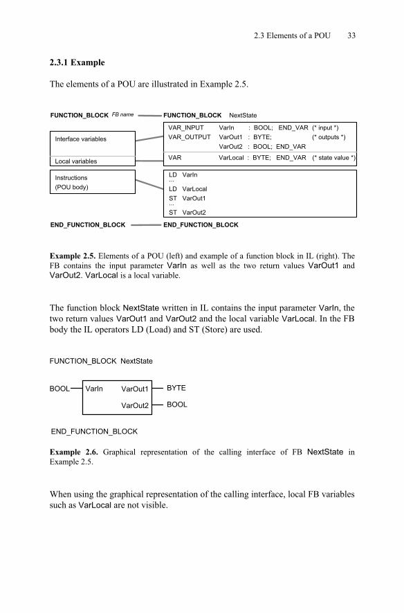
The elements of a POU are illustrated in Example 2.5.
VarIn : BOOL; END_VAR
LD VarIn
ST VarOut1
...
FUNCTION_BLOCK FB name
Instructions(POU body)
Interface variables
Local variables
FUNCTION_BLOCK NextState
VarOut1 : BYTE;VAR_OUTPUTVAR_INPUT
VAR
VarOut2 : BOOL; END_VAR
VarLocal : BYTE; END_VAR
ST VarOut2...
(* input *)(* outputs *)
(* state value *)
END_FUNCTION_BLOCK END_FUNCTION_BLOCK
LD VarLocal
Example 2.5. Elements of a POU (left) and example of a function block in IL (right). TheFB contains the input parameter VarIn as well as the two return values VarOut1 andVarOut2. VarLocal is a local variable.
The function block NextState written in IL contains the input parameter VarIn, the two return values VarOut1 and VarOut2 and the local variable VarLocal. In the FB body the IL operators LD (Load) and ST (Store) are used.
BOOL BYTEVarIn VarOut1
FUNCTION_BLOCK NextState
END_FUNCTION_BLOCK
BOOLVarOut2
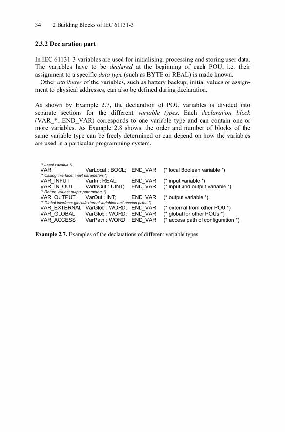
Example 2.6. Graphical representation of the calling interface of FB NextState inExample 2.5.
When using the graphical representation of the calling interface, local FB variables such as VarLocal are not visible.
34 2 Building Blocks of IEC 61131-3
2.3.2 Declaration part
In IEC 61131-3 variables are used for initialising, processing and storing user data. The variables have to be declared at the beginning of each POU, i.e. theirassignment to a specific data type (such as BYTE or REAL) is made known.
Other attributes of the variables, such as battery backup, initial values or assign-ment to physical addresses, can also be defined during declaration.
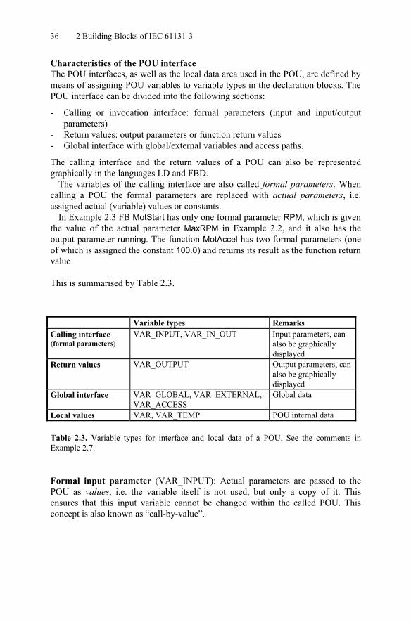
As shown by Example 2.7, the declaration of POU variables is divided intoseparate sections for the different variable types. Each declaration block(VAR_*...END_VAR) corresponds to one variable type and can contain one ormore variables. As Example 2.8 shows, the order and number of blocks of thesame variable type can be freely determined or can depend on how the variablesare used in a particular programming system.
(* Local variable *)VAR VarLocal : BOOL; END_VAR (* local Boolean variable *)(* Calling interface: input parameters *)VAR_INPUT VarIn : REAL; END_VAR (* input variable *)VAR_IN_OUT VarInOut : UINT; END_VAR (* input and output variable *)(* Return values: output parameters *)VAR_OUTPUT VarOut : INT; END_VAR (* output variable *)(* Global interface: global/external variables and access paths *)VAR_EXTERNAL VarGlob : WORD; END_VAR (* external from other POU *)VAR_GLOBAL VarGlob : WORD; END_VAR (* global for other POUs *)VAR_ACCESS VarPath : WORD; END_VAR (* access path of configuration *)
Example 2.7. Examples of the declarations of different variable types

2.3 Elements of a POU 35
(* Declaration block 1 *)VAR VarLocal1, VarLocal2, VarLocal3: BOOL; END_VAR (* Declaration block 2 *)VAR_INPUT VarIn1 : REAL; END_VAR (* Declaration block 3 *)VAR_OUTPUT VarOut : INT; END_VAR (* Declaration block 4 *)VAR VarLocal4, VarLocal5 : BOOL; END_VAR (* Declaration block 5 *)VAR_INPUT VarIn2, VarIn3 : REAL; END_VAR (* Declaration block 6 *)VAR_INPUT VarIn4 : REAL; END_VAR
Example 2.8. Examples of declaration blocks: the order and number of the blocks is notspecified in IEC 61131-3.
Types of variables in POUs.As shown by Table 2.2, different types of variables may be used depending on the POU type:
Variable type Permitted in:PROGRAM FUNCTION_BLOCK FUNCTION
VAR yes yes yesVAR_INPUT yes yes yesVAR_OUTPUT yes yes yesVAR_IN_OUT yes yes yesVAR_EXTERNAL yes yes noVAR_GLOBAL yes no noVAR_ACCESS yes no noVAR_TEMP yes yes no
Table 2.2. Variable types used in the three types of POU
As Table 2.2 shows, all variable types can be used in programs. Function blockscannot make global variables available to other POUs. This is only permitted inprograms, resources and configurations. FBs access global data using the variabletype VAR_EXTERNAL.
Functions have the most restrictions because only local and input and outputvariables are permitted in them. They return their calculation result using thefunction return value.
Except for local variables, all variable types can be used to import data into andexport data from a POU. This makes data exchange between POUs possible. Thefeatures of this POU interface will be considered in more detail in the next section.
36 2 Building Blocks of IEC 61131-3
Characteristics of the POU interfaceThe POU interfaces, as well as the local data area used in the POU, are defined by means of assigning POU variables to variable types in the declaration blocks. The POU interface can be divided into the following sections:
- Calling or invocation interface: formal parameters (input and input/outputparameters)
- Return values: output parameters or function return values- Global interface with global/external variables and access paths.
The calling interface and the return values of a POU can also be representedgraphically in the languages LD and FBD.
The variables of the calling interface are also called formal parameters. Whencalling a POU the formal parameters are replaced with actual parameters, i.e.assigned actual (variable) values or constants.
In Example 2.3 FB MotStart has only one formal parameter RPM, which is given the value of the actual parameter MaxRPM in Example 2.2, and it also has theoutput parameter running. The function MotAccel has two formal parameters (oneof which is assigned the constant 100.0) and returns its result as the function return value
This is summarised by Table 2.3.
Variable types RemarksCalling interface (formal parameters)
VAR_INPUT, VAR_IN_OUT Input parameters, can also be graphically displayed
Return values VAR_OUTPUT Output parameters, can also be graphically displayed
Global interface VAR_GLOBAL, VAR_EXTERNAL, VAR_ACCESS
Global data
Local values VAR, VAR_TEMP POU internal data
Table 2.3. Variable types for interface and local data of a POU. See the comments inExample 2.7.
Formal input parameter (VAR_INPUT): Actual parameters are passed to thePOU as values, i.e. the variable itself is not used, but only a copy of it. Thisensures that this input variable cannot be changed within the called POU. Thisconcept is also known as “call-by-value”.

2.3 Elements of a POU 37
Formal input/output parameter (VAR_IN_OUT): Actual parameters are passed to the called POU in the form of a pointer to their storage location, i.e. the variable itself is used. It can thus be read and changed by the called POU. Such changeshave an automatic effect on the variables declared outside the called POU. Thisconcept is also known as “call-by-reference”.
By working with references to storage locations this variable type providespointers like those used in high-level languages like C for return values fromsubroutines.
Formal output parameters, return values (VAR_OUTPUT) are not passed tothe called POU, but are provided by that POU as values. They are therefore notpart of the calling interface. They appear together with VAR_INPUT andVAR_IN_OUT in graphical representation, but in textual languages such as IL orST their values are read after calling the POU.
The method of passing to the calling POU is also “return-by-value”, allowing the values to be read by the calling instance (FB or PROG). This ensures that theoutput parameters of a POU are protected against changes by a calling POU. When a POU of type PROGRAM is called, the output parameters are provided togetherwith the actual parameters by the resource and assigned to appropriate variablesfor further processing (see examples in Chapter 6).
If a POU call uses complex arrays or data structures as variables, the use ofVAR_IN_OUT results in more efficient programs, as it is not the variablesthemselves (VAR_INPUT and VAR_OUTPUT) that have to be copied at runtime, but only their respective pointers. However such variables are not protectedagainst (unwelcome) manipulation by the called POU.
External and internal access to POU variables Formal parameters and return values have the special property of being visibleoutside their POU: the calling POU can (but need not) use their names explicitlyfor setting input values.
This makes it easier to document the POU calling interface and parameters maybe omitted and/or their sequence may be altered. In this context input and outputvariables are also protected against unauthorised reading and writing.
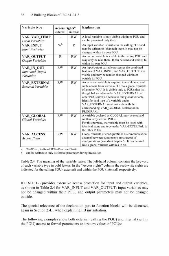
Table 2.4 summarises all variable types and their meaning. Access rights aregiven for each variable type, indicating whether the variable:
- is visible to the calling POU (“external”) and can be read or written to there- can be read or written to within the POU (“internal”) in which it is defined.
38 2 Building Blocks of IEC 61131-3
Variable type Access rightsa Explanationexternal internal
VAR, VAR_TEMPLocal Variables
- RW A local variable is only visible within its POU and can be processed only there.
VAR_INPUTInput Variables
Wb R An input variable is visible to the calling POU and may be written to (changed) there. It may not be changed within its own POU.
VAR_OUTPUTOutput Variables
R RW An output variable is visible to the calling POU and may only be read there. It can be read and written to within its own POU.
VAR_IN_OUTInput and Output Variables
RW RW An input/output variable possesses the combined features of VAR_INPUT and VAR_OUTPUT: it is visible and may be read or changed within or outside its POU.
VAR_EXTERNALExternal Variables
RW RW An external variable is required to enable read and write access from within a POU to a global variable of another POU. It is visible only to POUs that list this global variable under VAR_EXTERNAL; all other POUs have no access to this global variable. Identifier and type of a variable under VAR_EXTERNAL must coincide with the corresponding VAR_GLOBAL declaration in PROGRAM.
VAR_GLOBALGlobal Variables
RW RW A variable declared as GLOBAL may be read and written to by several POUs.For this purpose, the variable must be listed with identical name and type under VAR-EXTERNAL in the other POUs.
VAR_ACCESSAccess Paths
RW RW Global variable of configurations as communication channel between components (resources) of configurations (see also Chapter 6). It can be used like a global variable within a POU.
a W=Write, R=Read, RW=Read and Writeb can be written to only as formal parameter during invocation
Table 2.4. The meaning of the variable types. The left-hand column contains the keywordof each variable type in bold letters. In the “Access rights” column the read/write rights are indicated for the calling POU (external) and within the POU (internal) respectively.
IEC 61131-3 provides extensive access protection for input and output variables,as shown in Table 2.4 for VAR_INPUT and VAR_OUTPUT: input variables maynot be changed within their POU, and output parameters may not be changedoutside.
The special relevance of the declaration part to function blocks will be discussedagain in Section 2.4.1 when explaining FB instantiation.
The following examples show both external (calling the POU) and internal (within the POU) access to formal parameters and return values of POUs:
2.3 Elements of a POU 39
FUNCTION_BLOCK FBTwo FUNCTION_BLOCK FBOneVAR_INPUT
VarIn : BYTE;END_VAR
VAR ExampleFB : FBTwo; END_VAR
VAR_OUTPUTVarOut : BYTE;
END_VARVAR VarLocal : BYTE;END_VAR...LD VarInAND VarLocalST VarOut...
…LD 44ST ExampleFB.VarInCAL ExampleFB (* FB call *)LD ExampleFB.VarOut...
END_FUNCTION_BLOCK END_FUNCTION_BLOCK
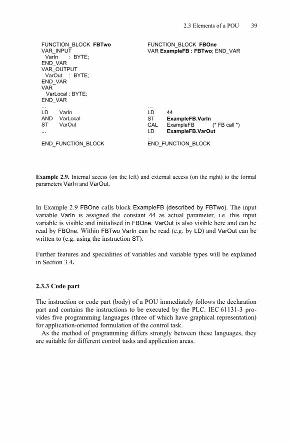
Example 2.9. Internal access (on the left) and external access (on the right) to the formalparameters VarIn and VarOut.
In Example 2.9 FBOne calls block ExampleFB (described by FBTwo). The inputvariable VarIn is assigned the constant 44 as actual parameter, i.e. this inputvariable is visible and initialised in FBOne. VarOut is also visible here and can be read by FBOne. Within FBTwo VarIn can be read (e.g. by LD) and VarOut can bewritten to (e.g. using the instruction ST).
Further features and specialities of variables and variable types will be explainedin Section 3.4.
2.3.3 Code part
The instruction or code part (body) of a POU immediately follows the declarationpart and contains the instructions to be executed by the PLC. IEC 61131-3 pro-vides five programming languages (three of which have graphical representation)for application-oriented formulation of the control task.
As the method of programming differs strongly between these languages, theyare suitable for different control tasks and application areas.

40 2 Building Blocks of IEC 61131-3
Here is a general guide to the languages:
SFC Sequential Function Chart: For breaking down the control task into parts which can be executed sequentially and in parallel, as well as for controlling their overall execution. SFC very clearly describes the program flow by defining which actions of the controlled process will be enabled, disabled or terminated at any one time. IEC 61131-3 emphasises the importance of SFC as an Aid for Structuring PLC programs.
LD Ladder Diagram: Graphical connection (“circuit diagram”) of Boolean variables (contacts and coils), geometrical view of a circuit similar to earlier relay controls. POUs written in LD are divided into sections known as networks.
FBD Function Block Diagram: Graphical connection of arithmetic, Boolean or other functional elements and function blocks. POUs written in FBD are divided into networks like those in LD. Boolean FBD networks can often be represented in LD and vice versa.
IL Instruction List: Low-level machine-oriented language offered by most of the programming systems
ST Structured Text: High-level language (similar to PASCAL) for control tasks as well as complex (mathematical) calculations.
Table 2.5. Features of the programming languages of IEC 61131-3
In addition, the standard explicitly allows the use of other programming languages (e.g. C or BASIC), which fulfil the following basic requirements of PLC pro-gramming:
- The use of variables must be implemented in the same way as in the otherprogramming languages of IEC 61131-3, i.e. compliant with the declarationpart of a POU.
- Calls of functions and function blocks must adhere to the standard, especiallycalls of standard functions and standard function blocks.
- There must be no inconsistencies with the other programming languages orwith the structuring aid SFC.
Details of these standard programming languages, their individual usage and theirrepresentation are given in Chapter 4.
2.4 The Function Block 41
2.4 The Function Block
Function blocks are the main building blocks for structuring PLC programs. Theyare called by programs and FBs and can themselves call functions as well as other FBs.
In this section the basic features of function blocks will be explained. A detailed example of an FB can be found in Appendix C.
The concept of the “instantiation of FBs” is of great importance in IEC 61131-3and is an essential distinguishing criterion between the three POU types. Thisconcept will therefore be introduced before explaining the other features of POUs.
2.4.1 Instances of function blocks
What is an “instance”?The creation of variables by the programmer by specifying the variable’s name and data type in the declaration is called instantiation.
In the following Example 2.10 the variable Valve is an instance of data typeBOOL:
Valve : BOOL; (* Boolean variable *)
Motor1 : MotorType; (* FB instance *)
Name of variable data type
Name of FB instance FB type (user-defined)
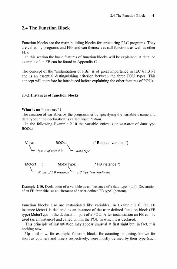
Example 2.10. Declaration of a variable as an “instance of a data type” (top). Declarationof an FB “variable” as an “instance of a user-defined FB type” (bottom).
Function blocks also are instantiated like variables: In Example 2.10 the FBinstance Motor1 is declared as an instance of the user-defined function block (FBtype) MotorType in the declaration part of a POU. After instantiation an FB can be used (as an instance) and called within the POU in which it is declared.
This principle of instantiation may appear unusual at first sight but, in fact, it isnothing new.
Up until now, for example, function blocks for counting or timing, known forshort as counters and timers respectively, were mostly defined by their type (such
42 2 Building Blocks of IEC 61131-3
as direction of counting or timing behaviour) and by a number given by the user,e.g. Counter “C19”.
Instead of this absolute number the standard IEC 61131-3 requires a (symbolic) variable name combined with the specification of the desired timer or counter type. This has to be declared in the declaration part of the POU. The programmingsystem can automatically generate internal, absolute numbers for these FBvariables when compiling the POU into machine code for the PLC.
With the aid of these variable names the PLC programmer can use differenttimers or counters of the same type in a transparent manner and without the need to check name conflicts.
By means of instantiation IEC 61131-3 unifies the usage of manufacturer-dependent FBs (typically timers and counters) and user-defined FBs. Instancenames correspond to the symbolic names or so-called symbols used by many PLCprogramming systems. Similarly, an FB type corresponds to its calling interface. In fact, FB instances provide much more than this: “Structure” and “Memory” forFBs will be explained in the next two subsections.
The term “function block” is often used with two slightly different meanings: itserves as a synonym for the FB instance name as well as for the FB type (= nameof the FB itself). In this book “function block” means FB type, while an FBinstance will always be explicitly indicated as an instance name.
Example 2.11 shows a comparison between the declarations of function blocks(here only standard FBs) and variables:
VARFillLevel : UINT; (* unsigned integer variable *)EmStop : BOOL; (* Boolean variable *)Time9 : TON; (* timer of type on-delay *)Time13 : TON; (* timer of type on-delay *)CountDown : CTD; (* down-counter *)GenCounter : CTUD; (* up-down counter *)
END_VAR
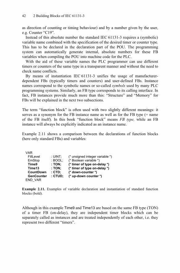
Example 2.11. Examples of variable declaration and instantiation of standard functionblocks (bold).
Although in this example Time9 and Time13 are based on the same FB type (TON) of a timer FB (on-delay), they are independent timer blocks which can beseparately called as instances and are treated independently of each other, i.e. theyrepresent two different “timers”.
2.4 The Function Block 43
FB instances are visible and can be used within the POU in which they aredeclared. If they are declared as global, all other POUs can use them as well (with VAR_EXTERNAL).
Functions, on the other hand, are always visible project-wide and can be calledfrom any POU without any further need of declaration. Similarly FB types areknown project-wide and can be used in any POU for the declaration of instances.
The declaration and calling of standard FBs will be described in detail inChapter 5. Their usage in the different programming languages is explained inChapter 4.
Instance means “structure”.The concept of instantiation, as applied in the examples of timer or counter FBs,results in structured variables, which:
- describe the FB calling interface like a data structure,- contain the actual status of a timer or counter,- represent a method for calling FBs.
This allows flexible parameter assignment when calling an FB, as can be seenbelow in the example of an up/down counter:
VARCounter : CTUD; (* up/down counter *)
END_VAR
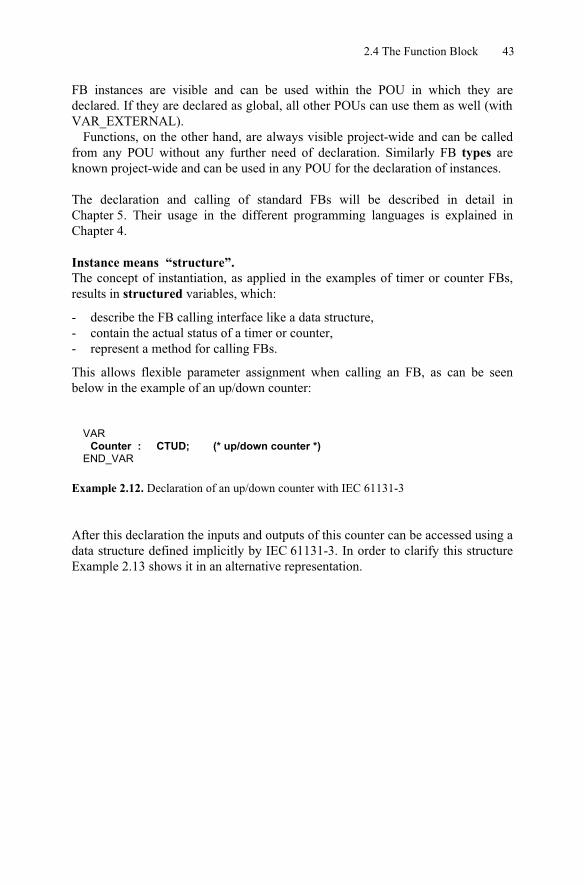
Example 2.12. Declaration of an up/down counter with IEC 61131-3
After this declaration the inputs and outputs of this counter can be accessed using a data structure defined implicitly by IEC 61131-3. In order to clarify this structureExample 2.13 shows it in an alternative representation.
44 2 Building Blocks of IEC 61131-3
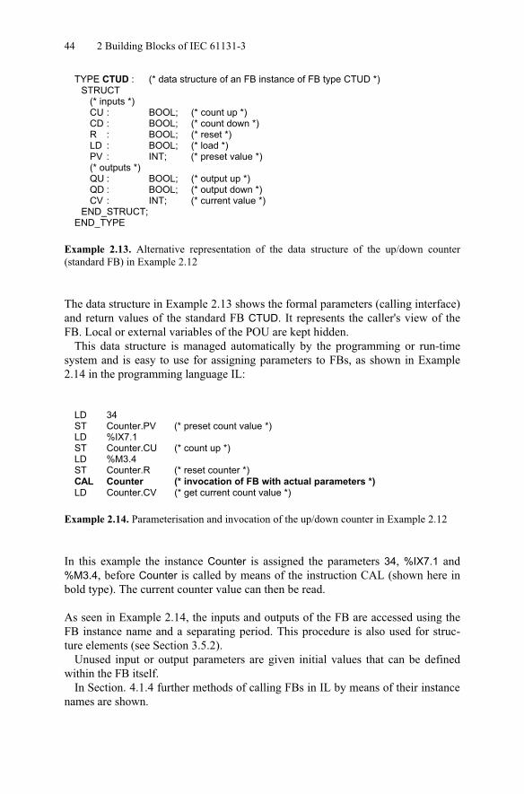
TYPE CTUD : (* data structure of an FB instance of FB type CTUD *)STRUCT
(* inputs *)CU : BOOL; (* count up *)CD : BOOL; (* count down *)R : BOOL; (* reset *)LD : BOOL; (* load *)PV : INT; (* preset value *)(* outputs *)QU : BOOL; (* output up *)QD : BOOL; (* output down *)CV : INT; (* current value *)
END_STRUCT;END_TYPE
Example 2.13. Alternative representation of the data structure of the up/down counter(standard FB) in Example 2.12
The data structure in Example 2.13 shows the formal parameters (calling interface) and return values of the standard FB CTUD. It represents the caller's view of theFB. Local or external variables of the POU are kept hidden.
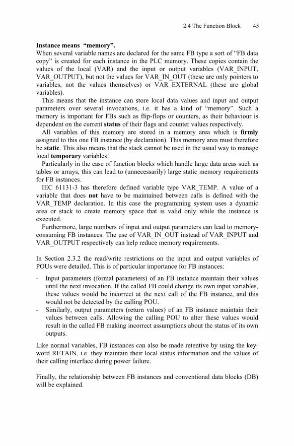
This data structure is managed automatically by the programming or run-timesystem and is easy to use for assigning parameters to FBs, as shown in Example2.14 in the programming language IL:
LD 34ST Counter.PV (* preset count value *)LD %IX7.1ST Counter.CU (* count up *)LD %M3.4ST Counter.R (* reset counter *)CAL Counter (* invocation of FB with actual parameters *)LD Counter.CV (* get current count value *)
Example 2.14. Parameterisation and invocation of the up/down counter in Example 2.12
In this example the instance Counter is assigned the parameters 34, %IX7.1 and%M3.4, before Counter is called by means of the instruction CAL (shown here inbold type). The current counter value can then be read.
As seen in Example 2.14, the inputs and outputs of the FB are accessed using theFB instance name and a separating period. This procedure is also used for struc-ture elements (see Section 3.5.2).
Unused input or output parameters are given initial values that can be definedwithin the FB itself.
In Section. 4.1.4 further methods of calling FBs in IL by means of their instance names are shown.
2.4 The Function Block 45
Instance means “memory”.When several variable names are declared for the same FB type a sort of “FB data copy” is created for each instance in the PLC memory. These copies contain thevalues of the local (VAR) and the input or output variables (VAR_INPUT,VAR_OUTPUT), but not the values for VAR_IN_OUT (these are only pointers to variables, not the values themselves) or VAR_EXTERNAL (these are globalvariables).
This means that the instance can store local data values and input and outputparameters over several invocations, i.e. it has a kind of “memory”. Such amemory is important for FBs such as flip-flops or counters, as their behaviour isdependent on the current status of their flags and counter values respectively.
All variables of this memory are stored in a memory area which is firmlyassigned to this one FB instance (by declaration). This memory area must therefore be static. This also means that the stack cannot be used in the usual way to manage local temporary variables!
Particularly in the case of function blocks which handle large data areas such astables or arrays, this can lead to (unnecessarily) large static memory requirementsfor FB instances.
IEC 61131-3 has therefore defined variable type VAR_TEMP. A value of avariable that does not have to be maintained between calls is defined with theVAR_TEMP declaration. In this case the programming system uses a dynamicarea or stack to create memory space that is valid only while the instance isexecuted.
Furthermore, large numbers of input and output parameters can lead to memory-consuming FB instances. The use of VAR_IN_OUT instead of VAR_INPUT andVAR_OUTPUT respectively can help reduce memory requirements.
In Section 2.3.2 the read/write restrictions on the input and output variables ofPOUs were detailed. This is of particular importance for FB instances:
- Input parameters (formal parameters) of an FB instance maintain their valuesuntil the next invocation. If the called FB could change its own input variables, these values would be incorrect at the next call of the FB instance, and thiswould not be detected by the calling POU.
- Similarly, output parameters (return values) of an FB instance maintain theirvalues between calls. Allowing the calling POU to alter these values wouldresult in the called FB making incorrect assumptions about the status of its own outputs.
Like normal variables, FB instances can also be made retentive by using the key-word RETAIN, i.e. they maintain their local status information and the values oftheir calling interface during power failure.
Finally, the relationship between FB instances and conventional data blocks (DB)will be explained.
46 2 Building Blocks of IEC 61131-3
Relationship between FB instances and data blocks.Before calling a conventional FB, which has no local data memory (besides
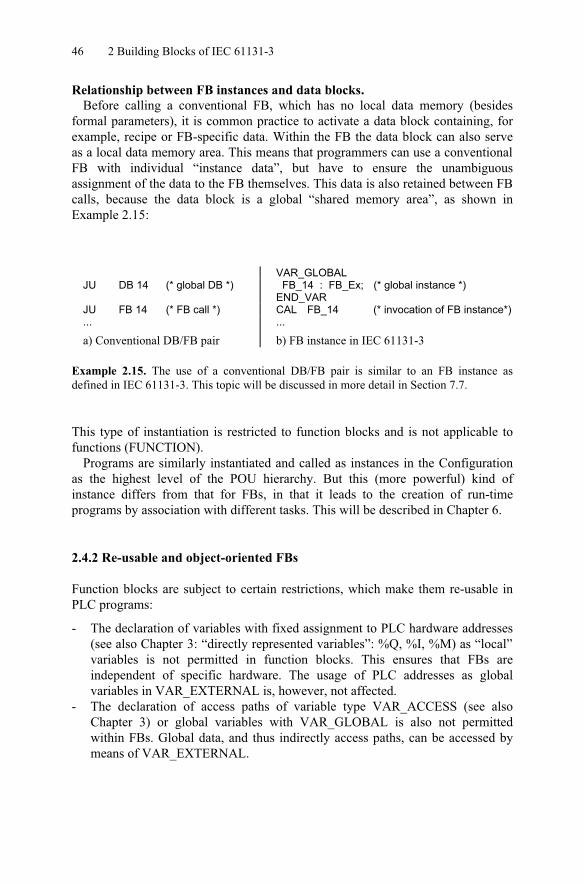
formal parameters), it is common practice to activate a data block containing, forexample, recipe or FB-specific data. Within the FB the data block can also serveas a local data memory area. This means that programmers can use a conventional FB with individual “instance data”, but have to ensure the unambiguousassignment of the data to the FB themselves. This data is also retained between FB calls, because the data block is a global “shared memory area”, as shown inExample 2.15:
VAR_GLOBALJU DB 14 (* global DB *) FB_14 : FB_Ex; (* global instance *)
END_VARJU FB 14 (* FB call *) CAL FB_14 (* invocation of FB instance*)... ...
a) Conventional DB/FB pair b) FB instance in IEC 61131-3
Example 2.15. The use of a conventional DB/FB pair is similar to an FB instance asdefined in IEC 61131-3. This topic will be discussed in more detail in Section 7.7.
This type of instantiation is restricted to function blocks and is not applicable tofunctions (FUNCTION).
Programs are similarly instantiated and called as instances in the Configurationas the highest level of the POU hierarchy. But this (more powerful) kind ofinstance differs from that for FBs, in that it leads to the creation of run-timeprograms by association with different tasks. This will be described in Chapter 6.
2.4.2 Re-usable and object-oriented FBs
Function blocks are subject to certain restrictions, which make them re-usable inPLC programs:
- The declaration of variables with fixed assignment to PLC hardware addresses(see also Chapter 3: “directly represented variables”: %Q, %I, %M) as “local” variables is not permitted in function blocks. This ensures that FBs areindependent of specific hardware. The usage of PLC addresses as globalvariables in VAR_EXTERNAL is, however, not affected.
- The declaration of access paths of variable type VAR_ACCESS (see alsoChapter 3) or global variables with VAR_GLOBAL is also not permittedwithin FBs. Global data, and thus indirectly access paths, can be accessed bymeans of VAR_EXTERNAL.
2.4 The Function Block 47
- External data can only be passed to the FB by means of the POU interfaceusing parameters and external variables. There is no “inheritance”, as in someother programming languages.
As a result of these features, function blocks are also referred to as encapsulated,which indicates that they can be used universally and are free from unwelcomeside effects during execution - an important property for parts of PLC programs.Local FB data and therefore the FB function do not directly rely on globalvariables, I/O or system-wide communication paths. FBs can manipulate such data areas only indirectly via their (well-documented) interface.
The FB instance model with the properties of “structure” and “memory” wasintroduced in the previous section. Together with the property of encapsulation for re-usability a very new view of function blocks appears. This can be summarisedas follows:
“A function block is an independent, encapsulated data structurewith a defined algorithm working on this data.”
The algorithm is represented by the code part of the FB. The data structure corres-ponds to the FB instance and can be “called”, something which is not possible with normal data structures. From each FB type any number of instances can bederived, each independent of the other. Each instance has a unique name with itsown data area.
Because of this, IEC 61131-3 considers function blocks to be “object-oriented”.These features should not, however, be confused with those of today’s modern“object-oriented programming languages (→OOP)” such as, for example, C# withits class hierarchy!
To summarise, FBs work on their own data area containing input, output andlocal variables. In previous PLC programming systems FBs usually worked onglobal data areas such as flags, shared memory, I/O and data blocks.
2.4.3 Types of variables in FBs
A function block can have any number of input and output parameters, or evennone at all, and can use local as well as external variables.
In addition or as an alternative to making a whole FB instance retentive, local or output variables can also be declared as retentive within the declaration part of the FB.
Unlike the FB instance itself which can be declared retentive using RETAIN, the values of input or input/output parameters cannot be declared retentive in the FBdeclaration part (RETAIN) as these are passed by the calling POU and have to be declared retentive there.
For VAR_IN_OUT it should be noted that the pointers to variables can bedeclared retentive in an instance using the qualifier RETAIN. The corresponding

48 2 Building Blocks of IEC 61131-3
values themselves can, however, be lost if they are not also declared as retentive in the calling POU.
Due to the necessary hardware-independence, directly represented variables(I/Os) may not be declared as local variables in FBs, such variables may only be“imported” as global variables using VAR_EXTERNAL.
One special feature of variable declaration in IEC 61131-3 are the so-called edge-triggered parameters. The standard provides the standard FBs R_TRIG andF_TRIG for rising and falling edge detection (see also Chapter 5).
The use of edge detection as an attribute of variable types is only possible forinput variables (see Section 3.5.4).
FBs are required for the implementation of some typical basic PLC functions, such as timers and counters, as these must maintain their status information (instancedata). IEC 61131-3 defines several standard FBs that will be described in moredetail and with examples in Chapter 5
2.5 The Function
The basic idea of a function (FUN) as defined by IEC 61131-3 is that theinstructions in the body of a function that are performed on the values of the input variables result in an unambiguous function value (free from side effects). In thissense functions can be seen as manufacturer- or application-specific extensions ofthe PLC’s set of operations.
The following simple rule is valid for functions: the same input values alwaysresult in the same output values and function (return) value. This is independent of how often or at what time the function is called. Unlike FBs, functions do not have a memory.
Functions can be used as IL operators (instructions) as well as operands in STexpressions. Like FB types, but unlike FB instances, functions are also accessibleproject-wide, i.e. known to all POUs of a PLC project.
For the purpose of simplifying and unifying the basic functionality of a PLCsystem, IEC 61131-3 predefines a set of frequently used standard functions, whose features, run-time behaviour and calling interface are standardised (see alsoChapter 5).
With the help of user-defined functions this collection can be extended toinclude device-specific extensions or application-specific libraries.
A detailed example of a function can be found in Appendix C. Functions haveseveral restrictions in comparison to other POU types. These restrictions arenecessary to ensure that the functions are truly independent (free of any side
2.5 The Function 49
effects) and to allow for the use of functions within expressions, e.g. in ST. Thiswill be dealt with in detail in the following section.
2.5.1 Types of variables in functions and the function value
Functions have any number of input and output parameters and exactly onefunction (return) value.
The function value can be of any data type, including derived data types. Thus a simple Boolean value or a floating-point double word is just as valid as an array or a complex data structure consisting of several data elements (multi-elementvariable), as described in Chapter 3.
Each programming language of IEC 61131-3 uses the function name as a special variable within the function body in order to explicitly assign a function value.
As functions always return the same result when provided with the same inputparameters, they may not store temporary results, status information or internaldata between their invocations, i.e. they operate “without memory”.
Functions can use local variables for intermediate results, but these will be lostwhen terminating the function. Local variables can therefore not be declared asretentive.
Functions may not call function blocks such as timers, counters or edge detec-tors. Furthermore, the use of global variables within functions is not permitted.
The standard does not stipulate how a PLC system should treat functions and thecurrent values of their variables after a power failure. The POU that calls thefunction is therefore responsible for backing up variables where necessary. In anycase it makes sense to use FBs instead of functions if important data is beingprocessed.
Furthermore, in functions (as in FBs) the declaration of directly representedvariables (I/O addresses) is not permitted.
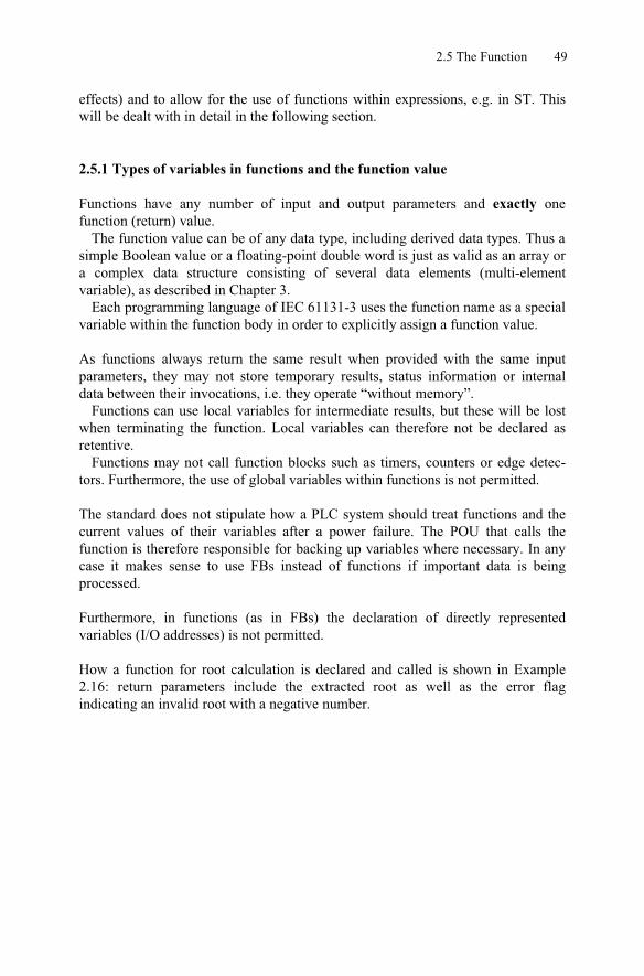
How a function for root calculation is declared and called is shown in Example2.16: return parameters include the extracted root as well as the error flagindicating an invalid root with a negative number.
50 2 Building Blocks of IEC 61131-3
FUNCTION SquareRoot : INT (* square root calculation *)(* start of declaration part *)
VAR_INPUT (* Input parameter *)VarIn : REAL; (* input variable *)
END_VARVAR_TEMP (* temporary values *)
Result : REAL; (* local variable *)END_VARVAR_OUTPUT (* output parameter *)
Error : BOOL; (* flag for root from neg. number *)END_VAR
(* start of instruction part *)LD VarIn (* load input variable *)LT 0 (* negative number? *)JMPC M_error (* error case *)LD VarIn (* load input variable *)SQRT (* calculate square root *)ST Result (* result is ok *)LD FALSE (* logical “0” for error flag: reset *)ST Error (* reset error flag *)JMP M_end (* done, jump to FUN end *)M_error: (* handling of error “negative number” *)LD 0 (* zero, because of invalid result in case of error *)ST Result (* reset result *)LD TRUE (* logical “1” for error flag: set *)ST Error (* set error flag *)M_end:LD Result (* result will be in function value! *)RET
(* FUN end *)END_FUNCTION
Example 2.16. Declaration and call of a function “Square root calculation with error” inIL.
2.6 The Program
Functions and function blocks constitute “subroutines”, whereas POUs of typePROGRAM build the PLC’s “main program”. On multitasking-capable controllerhardware several main programs can be executed simultaneously. ThereforePROGRAMs have special features compared to FBs. These features will beexplained in this section.

2.6 The Program 51
In addition to the features of FBs, a PLC programmer can use the followingfeatures in a PROGRAM:
- Declaration of directly represented variables to access the physical I/Oaddresses of the PLC (%Q, %I, %M) is allowed,
- Usage of VAR_ACCESS or VAR_GLOBAL is possible,- A PROGRAM is associated with a task within the configuration, in order to
form a run-time program, i.e. programs are not called explicitly by other POUs.
Variables can be assigned to the PLC I/Os in a PROGRAM by using directlyrepresented or symbolic variables as global or POU parameters.
Furthermore programs describe the mechanisms by which communication andglobal data exchange to other programs take place (inside and outside theconfiguration). The variable type VAR_ACCESS is used for this purpose.
These features can also be used at the resource and configuration levels. This is, in fact, to be recommended for complex PLC projects.
Because of the wide functionality of the POU PROGRAM it is possible, insmaller projects, to work without a configuration definition: the PROGRAM takes over the task of assigning the program to PLC hardware.
Such possibilities depend on the functionality of a programming system and will not be dealt with any further here.
A detailed example of a PROGRAM can be found in Appendix C.
The run-time properties and special treatment of a PROGRAM in the CPU areexpressed by associating the PROGRAM with TASKs. The program is instan-tiated, allowing it to be assigned to more than one task and to be executed several times simultaneously within the PLC. This instantiation differs, however from that for FB instances.
The assignment of programs to tasks is done in the CONFIGURATION and isexplained in Chapter 6.

52 2 Building Blocks of IEC 61131-3
2.7 The Execution control with EN and ENO
In the ladder diagram LD, functions have a special feature not used in the otherprogramming languages of IEC 61131-3: here the functions possess an additionalinput and output. These are the Boolean input EN (Enable In) and the Booleanoutput ENO (Enable Out).
LockOff NoErrorEN
In
Fun1
ENOVarIn VarOutOut
Example 2.17. Graphical invocation of a function with EN/ENO in LD
Example 2.17 shows the graphical representation for calling function Fun1 withEN and ENO in LD. In this example Fun1 will only be executed if input EN hasthe value logical “1” (TRUE), i.e. contact Lockoff is closed. After error-freeexecution of the POU the output ENO is similarly “1” (TRUE) and the variableNoError remains set.
With the aid of the EN/ENO pair it is possible to at least partially integrate anyfunction, even those whose inputs or function value are not Boolean, like Fun1 inExample 2.17, into the “power flow”. The meaning of EN/ENO based on thisconcept is summarised in Table 2.6:

2.7 The Execution control with EN and ENO 53
EN Explanationa ENOEN = FALSE If EN is FALSE when calling the POU, the code-
part of the function may not be executed. In this case output ENO will be set to FALSE upon exiting the unexecuted POU call in order to indicate that the POU has not been executed.Note for FB: Assignments to inputs are implementation independent in FB. The FB instance’s values of the previous call are retained. This is irrelevant in FUN (no memory).
ENO = FALSE
EN = TRUE If EN is TRUE when calling POU , the code-partof the POU can be executed normally. In this case ENO will initially be set to TRUE before startingthe execution.
ENO = TRUE
ENO can afterwards be set to TRUE or FALSE by instructions executed within the POU body.
ENO = individual value
If a program or system error (as described in Appendix E) occurs while executing the function ENO will be reset to FALSE by the PLC.
ENO = FALSE (error occurred)
a TRUE = logical “1”, FALSE = logical “0”
Table 2.6. Meaning of EN and ENO within functions
As can been seen from Table 2.6, EN and ENO determine the control flow in agraphical network by means of conditional function execution and error handlingin case of abnormal termination. EN can be connected not only to a single contact as in Example 2.17, but also with a sub-network of several contacts, thus setting a complex precondition. ENO can be similarly be evaluated by a more complex sub-network (e.g. contacts, coils and functions). These control flow operations shouldhowever be logically distinguished from other LD/FBD operations that representthe data flow of the PLC program.
These special inputs/outputs EN and ENO are not treated as normal functioninputs and outputs by IEC 61131-3, but are reserved only for the tasks describedabove. Timers or counters are typical examples of function blocks in this context.
The use of these additional inputs and outputs is not included in the otherIEC 61131-3 programming languages. In FBD the representation of EN/ENO isallowed as an additional feature.
The function call in Example 2.17 can be represented in IL if the programmingsystem supports EN/ENO as implicit system variables.
If a programming system supports the usage of EN and ENO, it is difficult toconvert POUs programmed with these into textual form. In order to make thispossible, EN/ENO would also have to be keywords in IL or ST and would need to be automatically generated there, as they are in LD/FBD. Then a function called in LD could be written in IL and could, for example, set the ENO flag in case of an
54 2 Building Blocks of IEC 61131-3
error. Otherwise only functions written in LD/FBD can be used in LD/FBDprograms. The standard, however, does not make any statement about how to useEN and ENO as keywords and graphical elements in LD/FBD in order to set andreset them.
On the other hand, it is questionable whether the usage of EN and ENO is ad-vantageous in comparison functions (std. FUN, see also Appendix A). A compa-rison function then has two Boolean outputs, each of which can be connected with a coil. If this comparison is used within a parallel branch of an LD network, ENO and the output Q have to be connected separately: ENO continues the parallelbranch while Q, in a sense, opens a new sub-network.
Because of this complexity only some of today’s IEC programming systems use EN/ENO. Instead of dictating the Boolean pair EN/ENO in LD/FBD there areother conceivable alternatives:
- EN and ENO can be used both implicitly and explicitly in all programminglanguages,
- Each function which can be called in LD/FBD must have at least one binaryinput and output respectively,
- Only standard functions have an EN/ENO pair (for error handling within thePLC system). This pair may not be used for user-defined functions.
The third alternative is the nearest to the definition in IEC 61131-3. This would,however, mean that EN and ENO are PLC system variables, which cannot bemanipulated by the PLC programmer.
2.8 Calling Functions and Function Blocks
In this section we will deal with the special features which have to be consideredwhen calling functions and function blocks. These features apply to standard aswell as user-defined functions and function blocks.
The following examples will be given in IL. The use of ST and graphical repre-sentation in LD and FBD are topics of Chapter 4.
2.8.1 Mutual calls of POUs
The following rules, visualised in Figure 2.7, can be applied to the mutual callingof POU types:
- PROGRAM may call FUNCTION_BLOCK and FUNCTION, but not theother way round,
- FUNCTION_BLOCK may call FUNCTION_BLOCK,- FUNCTION_BLOCK may call FUNCTION, but not the other way round,

2.8 Calling Functions and Function Blocks 55
- Calls of POUs may not be recursive, i.e. a POU may not call (an instance of)itself either directly or indirectly.
PROGRAM
FUNCTION_BLOCKFUNCTION
1 Program calls function or function block
2 Function calls function
3 Function block calls function or function block
FUNCTION FUNCTION FUNCTION_BLOCK
1
32
Figure 2.7. The three possible ways of invocation among the POU types
Programs and FB instances may call FB instances. Functions, on the other hand,may not call FB instances, as otherwise the independence (freedom from sideeffects) of functions could not be guaranteed.
Programs (PROGRAM) are instantiated to form run-time programs within theConfiguration by association with a TASK. They are then called by the Resource.
2.8.2 Recursive calls are invalid
IEC 1131-3 clearly defines that POUs may not call themselves (“recursion”) either directly or indirectly, i.e. a POU may not call a POU instance of the same typeand/or name. This would mean that a POU could “define itself” by using its ownname in its declaration or calling itself within its own body. Recursion is, however, usually permitted in other programming languages in the PC world.
If recursion were allowed, it would not be possible for the programming systemto calculate the maximum memory space needed by a recursive PLC program atrun time.
Recursion can always be replaced by corresponding iterative constructs, i.e. bybuilding program loops.

56 2 Building Blocks of IEC 61131-3
Both the following figures show examples of invalid calls:
INTINT
Par1Par2
FUNCTION Fun1 : BOOL
END_FUNCTION
BOOL
Par1 Par1Par2 Fun1Par2
Fun1
VAR_INPUTPar1, Par2 : INT;
FUNCTION Fun1 : BOOL
END_FUNCTION
LD Par1Fun1 Par2
END_VAR
ST Fun1
Example 2.18. Invalid recursive call of a function in graphical and IL representation:nested invocation.
In Example 2.18 the same function is called again within function Fun1.The top half of this example shows the declaration part of the function (input
variables Par1 and Par2 of data type INT and function value of type BOOL).In the bottom part, this function is called with the same input variables so that
there would be an endless (recursive) chain of calls at run time.
FUNCTION_BLOCK FunBlkVAR_INPUT
In1 : DINT; (* input variable *)END_VARVAR
InstFunBlk : FunBlk; (* improper instance of the same type *)Var1 : DINT; (* local variable *)
END_VAR...
CALC InstFunBlk (In1 := Var1); (* invalid recursive invocation! *)...END_FUNCTION_BLOCK
Example 2.19. Invalid recursive call of an FB in IL: nesting already in declaration part.
Example 2.19 shows function block FunBst, in whose local variable declaration(VAR) an instance InstFunBlk of its own type (FunBst) is declared. This instanceis called in the function body. This would result in endlessly deep nesting wheninstantiating the FB in the declaration, and the memory space required for theinstance at run time would be impossible to determine.
2.8 Calling Functions and Function Blocks 57
Programmers themselves or the programming/PLC system must check whetherunintentional recursive calling exists in the PLC program.
This checking can be carried out when creating the program by means of a POU calling tree, as the invalid use of recursion applies to FB types and not to theirinstance names. This is even possible if FB instance names are used as inputparameters (see also Section 2.8.6).
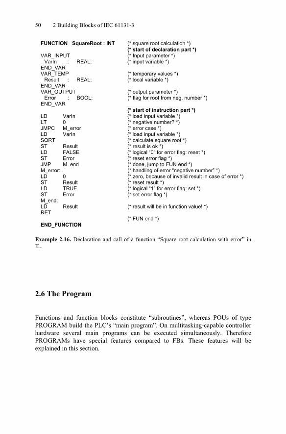
The following example shows how recursive calls can occur even if a function or FB instance does not directly call itself. It suffices if they mutually call each other.
INTINT
Par1Par2
FUNCTION Fun1 : BOOL
END_FUNCTION
BOOL
Par1 Par1Par2 Fun1Par2
Fun2
INTINT
Par1Par2
FUNCTION Fun2 : BOOL
END_FUNCTION
BOOL
Par1 Par1Par2 Fun1Par2
Fun1
Example 2.20. Recursion by mutual invocation in graphical representation
Such types of recursion are, on principle, not permitted in IEC 61131-3. Thecalling condition may be defined as follows: if a POU is called by POU A, thatPOU and all the POUs below it in the calling hierarchy may not use the name ofPOU A (FB instance or function name).
Unlike most of the modern high-level languages (such as C), recursion istherefore prohibited by IEC 61131-3. This helps protect PLC programs againstprogram errors caused by unintentional recursion.
2.8.3 Extendibility and overloading
Standard functions such as additions may have more than two input parameters.This is called input extension and will make use of the same function for multipleinput parameters clearer. A standard function or a standard function block type isoverloaded if these POUs can work with input data elements of various datatypes. These concepts are described in detail in Section 5.1.1.
58 2 Building Blocks of IEC 61131-3
2.8.4 Calling with formal parameters
When a FUN/FB is called, the input parameters are passed to the POU’s inputvariables. These input variables are also called formal parameters, i.e. they areplaceholders. The input parameters are known as actual parameters in order toexpress that they contain actual input values.
When calling a POU, the formal parameters may or may not be explicitlyspecified. This depends on the POU type (FUN or FB) and the programminglanguage used for the POU call (see also Chapter 4).
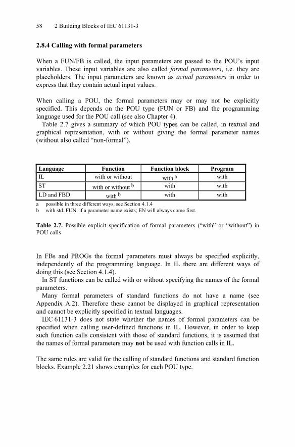
Table 2.7 gives a summary of which POU types can be called, in textual andgraphical representation, with or without giving the formal parameter names(without also called “non-formal”).
Language Function Function block ProgramIL with or without with a withST with or without b with withLD and FBD with b with with
a possible in three different ways, see Section 4.1.4b with std. FUN: if a parameter name exists; EN will always come first.
Table 2.7. Possible explicit specification of formal parameters (“with” or “without”) inPOU calls
In FBs and PROGs the formal parameters must always be specified explicitly,independently of the programming language. In IL there are different ways ofdoing this (see Section 4.1.4).
In ST functions can be called with or without specifying the names of the formal parameters.
Many formal parameters of standard functions do not have a name (seeAppendix A.2). Therefore these cannot be displayed in graphical representationand cannot be explicitly specified in textual languages.
IEC 61131-3 does not state whether the names of formal parameters can bespecified when calling user-defined functions in IL. However, in order to keepsuch function calls consistent with those of standard functions, it is assumed thatthe names of formal parameters may not be used with function calls in IL.
The same rules are valid for the calling of standard functions and standard function blocks. Example 2.21 shows examples for each POU type.
2.8 Calling Functions and Function Blocks 59
FB declaration: FUN declaration: PROG declaration:
FUNCTION_BLOCK FBlkVAR_INPUT
Par1 : TIME;Par2 : WORD;Par3 : INT;
END_VAR
FUNCTION Fctn : INTVAR_INPUT
Par1 : TIME;Par2 : WORD;Par3 : INT;
END_VAR
PROGRAM PrgrmVAR_GLOBAL
FunBlk : FBlk;VarGlob : INT;AT %IW4 : WORD;
END_VAR... (*instructions *)END_FUNCTION_BLOCK
... (*instructions *)END_FUNCTION
... (* instructions *)END_PROGRAM
(* 1. Invocations in IL *)LD t#20:12Fctn %IW4, VarGlob (* function call *)CAL FunBlk (Par1 := t#20:12, Par2 := %IW4, Par3 := VarGlob) (* FB call *)
(* 2. Invocations in ST *)Fctn (t#20:12, %IW4, VarGlob) (* function call *)Fctn (Par1 := t#20:12, Par2 := %IW4, Par3 := VarGlob); (* function call *)FunBlk (Par1 := t#20:12, Par2 := %IW4, Par3 := VarGlob); (* FB call *)
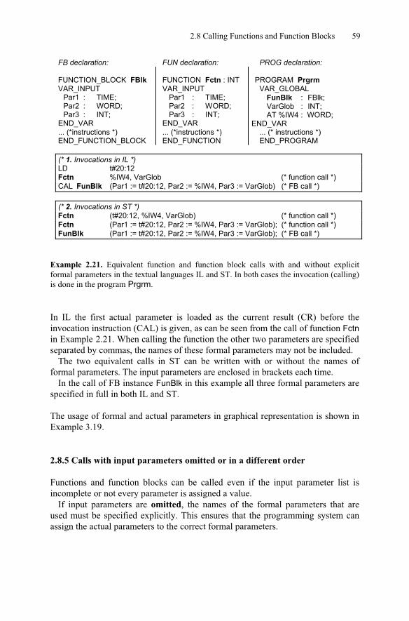
Example 2.21. Equivalent function and function block calls with and without explicitformal parameters in the textual languages IL and ST. In both cases the invocation (calling) is done in the program Prgrm.
In IL the first actual parameter is loaded as the current result (CR) before theinvocation instruction (CAL) is given, as can be seen from the call of function Fctnin Example 2.21. When calling the function the other two parameters are specified separated by commas, the names of these formal parameters may not be included.
The two equivalent calls in ST can be written with or without the names offormal parameters. The input parameters are enclosed in brackets each time.
In the call of FB instance FunBlk in this example all three formal parameters are specified in full in both IL and ST.
The usage of formal and actual parameters in graphical representation is shown inExample 3.19.
2.8.5 Calls with input parameters omitted or in a different order
Functions and function blocks can be called even if the input parameter list isincomplete or not every parameter is assigned a value.
If input parameters are omitted, the names of the formal parameters that areused must be specified explicitly. This ensures that the programming system canassign the actual parameters to the correct formal parameters.
60 2 Building Blocks of IEC 61131-3
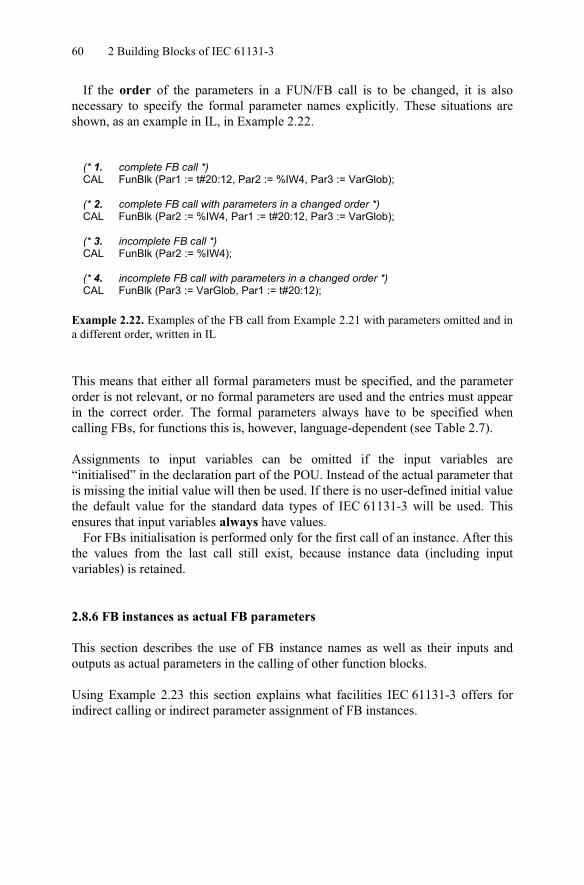
If the order of the parameters in a FUN/FB call is to be changed, it is alsonecessary to specify the formal parameter names explicitly. These situations areshown, as an example in IL, in Example 2.22.
(* 1. complete FB call *)CAL FunBlk (Par1 := t#20:12, Par2 := %IW4, Par3 := VarGlob);
(* 2. complete FB call with parameters in a changed order *)CAL FunBlk (Par2 := %IW4, Par1 := t#20:12, Par3 := VarGlob);
(* 3. incomplete FB call *)CAL FunBlk (Par2 := %IW4);
(* 4. incomplete FB call with parameters in a changed order *)CAL FunBlk (Par3 := VarGlob, Par1 := t#20:12);
Example 2.22. Examples of the FB call from Example 2.21 with parameters omitted and in a different order, written in IL
This means that either all formal parameters must be specified, and the parameterorder is not relevant, or no formal parameters are used and the entries must appear in the correct order. The formal parameters always have to be specified whencalling FBs, for functions this is, however, language-dependent (see Table 2.7).
Assignments to input variables can be omitted if the input variables are“initialised” in the declaration part of the POU. Instead of the actual parameter that is missing the initial value will then be used. If there is no user-defined initial value the default value for the standard data types of IEC 61131-3 will be used. Thisensures that input variables always have values.
For FBs initialisation is performed only for the first call of an instance. After this the values from the last call still exist, because instance data (including inputvariables) is retained.
2.8.6 FB instances as actual FB parameters
This section describes the use of FB instance names as well as their inputs andoutputs as actual parameters in the calling of other function blocks.
Using Example 2.23 this section explains what facilities IEC 61131-3 offers forindirect calling or indirect parameter assignment of FB instances.
2.8 Calling Functions and Function Blocks 61
FUNCTION_BLOCK MainFBVAR_IN_OUT
Time1 : TON; (* 1st instance of TON *)Time2 : TON; (* 2nd instance of TON *)
InstFB : SubFB; (* Instance of SubFB *)
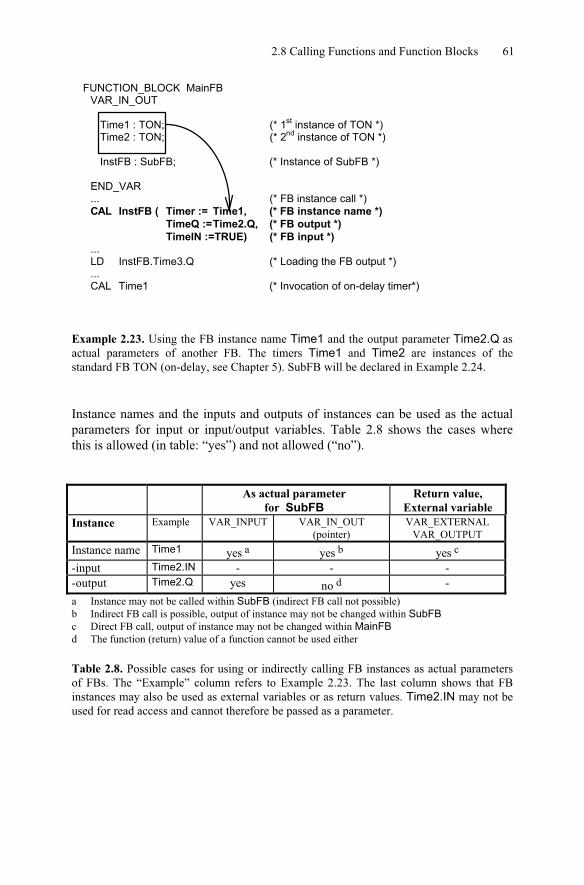
END_VAR... (* FB instance call *)CAL InstFB ( Timer := Time1, (* FB instance name *)
TimeQ :=Time2.Q, (* FB output *)TimeIN :=TRUE) (* FB input *)
...LD InstFB.Time3.Q (* Loading the FB output *)...CAL Time1 (* Invocation of on-delay timer*)
Example 2.23. Using the FB instance name Time1 and the output parameter Time2.Q as actual parameters of another FB. The timers Time1 and Time2 are instances of thestandard FB TON (on-delay, see Chapter 5). SubFB will be declared in Example 2.24.
Instance names and the inputs and outputs of instances can be used as the actualparameters for input or input/output variables. Table 2.8 shows the cases wherethis is allowed (in table: “yes”) and not allowed (“no”).
As actual parameterfor SubFB
Return value, External variable
Instance Example VAR_INPUT VAR_IN_OUT(pointer)
VAR_EXTERNALVAR_OUTPUT
Instance name Time1 yes a yes b yes c
-input Time2.IN - - --output Time2.Q yes no d -a Instance may not be called within SubFB (indirect FB call not possible)b Indirect FB call is possible, output of instance may not be changed within SubFBc Direct FB call, output of instance may not be changed within MainFBd The function (return) value of a function cannot be used either
Table 2.8. Possible cases for using or indirectly calling FB instances as actual parametersof FBs. The “Example” column refers to Example 2.23. The last column shows that FBinstances may also be used as external variables or as return values. Time2.IN may not beused for read access and cannot therefore be passed as a parameter.

62 2 Building Blocks of IEC 61131-3
As this summary shows, only certain combinations of function block instancenames and their inputs and outputs can be passed as actual parameters to functionblocks for each of the variable types.
VAR_INPUT: FB instances and their outputs cannot be called or altered withinSubFB if they are passed as VAR_INPUT. They may, however, be read.
VAR_IN_OUT: The output of an FB instance, whose pointer would be used here, is not allowed as a parameter for this variable type. An erroneous manipulation ofthis output can thus be prevented. Similarly, a pointer to the function value of afunction is not allowed as a parameter for a VAR_IN_OUT variable.
The instance passed as a parameter can then be called, thereby implementing anindirect FB call.
The outputs of the FB instance that has been passed may not be written to. FBinstance inputs may, however, be freely accessed.
VAR_EXTERNAL, VAR_OUTPUT: FB instances are called directly, theirinputs and outputs may only be read by the calling POU.
Example of an indirect FB call.Example 2.24 shows (together with Example 2.23) the use of some cases permitted in Table 2.8 within function block SubFB.

2.8 Calling Functions and Function Blocks 63
FUNCTION_BLOCK SubFBVAR_INPUT
TimeIN : BOOL; (* Boolean input variable *)TimeQ : BOOL; (* Boolean input variable *)
END_VARVAR_IN_OUT
Timer : TON; (* pointer to instance Time1 of TON – input/output variable *)END_VARVAR_OUTPUT
Time3 : TON; (* 3rd instance of TON *)END_VARVAR
Start : BOOL := TRUE; (* local Boolean variable *)END_VAR
...(* Indirect call of Time1 setting/checking the actual parameter values using Timer *)LD StartST Timer.IN (* starting of Timer Time1 *)CAL Timer (* calling the on-delay timer Time 1 indirectly *)LD Timer.Q (* checking the output of Time1 *)...(* Direct call of Time3; indirect access to Time2 *)LD TimeIN (*indirect checking of the input of Time2 is not possible *)ST Time3.IN (* starting the timer using Time3.IN *)CAL Time3 (* calling the on-delay timer Time3 directly *)LD Time3.Q (*checking the output using Time3.Q *)...LD TimeQ (*indirectly checking the output of Time 2 *)...END_FUNCTION_BLOCK
Example 2.24. Alternative ways of calling the on-delay FB Time1 from Example 2.23indirectly and usage of its inputs and outputs
This example shows the indirect call of FB Time1, whose instance name waspassed to FB SubFB as an input/output variable in Example 2.23. The functionblock SubFB is only assigned the FB instance name Time1 at the run time ofMainFB. In SubFB Time1 (as input variable Timer) is provided with the parameter Timer.IN and then called.
As shown with Example 2.24, it is also possible to access the inputs and outputs of an FB passed as an instance name. Here the instance inputs (Timer.IN) can beread and written to, whereas the outputs (as Timer.Q) can only be read.
The FB instance Time3 in this example serves as a comparison between thetreatment of input parameters and of the return values of an FB as output variables.
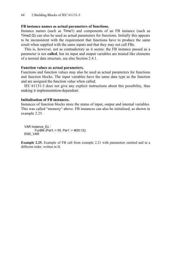
64 2 Building Blocks of IEC 61131-3
FB instance names as actual parameters of functions.Instance names (such as Time1) and components of an FB instance (such asTime2.Q) can also be used as actual parameters for functions. Initially this appears to be inconsistent with the requirement that functions have to produce the sameresult when supplied with the same inputs and that they may not call FBs.
This is, however, not as contradictory as it seems: the FB instance passed as aparameter is not called, but its input and output variables are treated like elements of a normal data structure, see also Section 2.4.1.
Function values as actual parameters.Functions and function values may also be used as actual parameters for functionsand function blocks. The input variables have the same data type as the functionand are assigned the function value when called.
IEC 61131-3 does not give any explicit instructions about this possibility, thusmaking it implementation-dependent.
Initialisation of FB instances.Instances of function blocks store the status of input, output and internal variables. This was called “memory“ above. FB instances can also be initialised, as shown in example 2.25.
VAR Instance_Ex :FunBlk (Par3 := 55, Par1 := t#20:12);
END_VAR
Example 2.25. Example of FB call from example 2.21 with parameters omitted and in adifferent order, written in IL

2.9 Summary of POU Features 65
2.9 Summary of POU Features
The following table summarises all essential POU features that have beenpresented and discussed in this chapter.
Feature Function Function Block ProgramInput parameter yes yes yesOutput parameter yes yes yesInput/output parameter yes yes yesFunction value yes no noInvocation of functions yes yes yesInvocation of function blocks no yes yesInvocation of programs no no noDeclaration of global variables no no yesAccess to external variables no yes yesDeclaration of directly represented variables a
no no yes
Declaration of local variables yes yes yesDeclaration of FB instances no yes yesOverloading b yes yes no
Extension c yes no noEdge detection possible no yes yesUsage of EN/ENO c yes yes noRetention of local and output variables
no yes yes
Indirect FB call no yes yesInitialisation of FB instances no yes noUsage of function values as input parameters d
yes yes yes
Usage of FB instances as input parameters
yes yes yes
Recursive invocation no no noa for function blocks only with VAR_EXTERNALb for standard functionsc for standard functions and standard function blocksd not in IL, otherwise: implementation-dependent
Table 2.9. An overview of the POU features summarising the important topics of this chap-ter. The entries “yes” or “no” mean “permitted” and “not permitted” for the correspondingPOU type respectively.

http://www.springer.com/978-3-642-12014-5