2. Basic Concepts - Meeting 2
39
BASIC CONCEPTS Dedison Gasni, Ph.D
-
Upload
anggiaanggrainiputri -
Category
Documents
-
view
13 -
download
3
description
hhhhh
Transcript of 2. Basic Concepts - Meeting 2

BASIC CONCEPTS
Dedison Gasni, Ph.D

Mechanism
� A mechanism has been defined by Reuleaux as “ a combination of rigid or resistant bodies so formed and connected that they move each other with definite relative motion”
� Function of a mechanism is to transmit or transform motion from one rigid body to another as part of the action of a machine.

Three types of basic elements of a
mechanism
� Gear systems, in which toothed members in contact transmit motion between rotating shaft.
� Cam Systems, where a uniform motion of an input member is converted into a non-uniform motion of member is converted into a non-uniform motion of the output member.
� Plane and spatial linkages are also useful in creating mechanical motions for a point or rigid body.

Linkages can be used for three basic
tasks
� Rigid body guidance, A rigid body guidance mechanism is used to guide a rigid body through a series of prescribed positions in space.
Path generation. A path generation mechanism will � Path generation. A path generation mechanism will guide a point on a rigid body through a series of points on a specified path in space.
� Function generation. A mechanism that creates an output motion that is a specified function of the input motion.
Terminologies of Mechanisms
� A link is defined as a rigid body having two or more pairing elements which connect it to other bodies for the purpose of transmitting force or motion.
In every machine, at least one link either occupies a � In every machine, at least one link either occupies a fixed position relative to the earth or carries the machine as a whole along with it during motion. This link is the frame of the machine and is called the fixed link.
� The combination of links and pairs without a fixed link is not a mechanism but a kinematic chain.

Link
Link is an (assumed) rigid body that possesses at least two nodes that are points for attachment to another links. A link is an (assumed) rigid body that possesses at least twonodes that are points for attachment to other links.


Joints
Joints is a connection between two or more links (at their nodes), which allows some motion, or potential motion, between the connected links.
Joints (also called kinematic pairs) can be classified in several
ways:
1. By the type of contact between the elements, line, point, or surface.2. By the number of degrees of freedom allowed at the joint.3. By the type of physical closure of the joint: either force or form
closed.4. By the number of links joined (order of the joint).
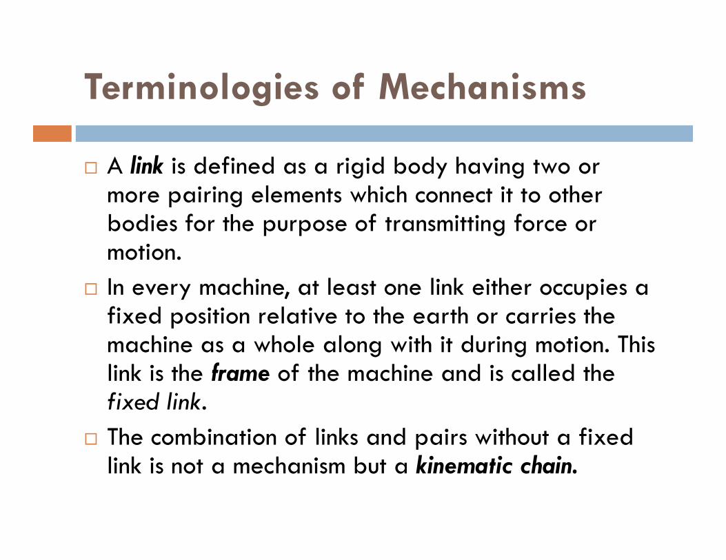
Pairing Elements
Pairing elements is the geometrical forms by which two members of a mechanism are joined together so that the relative motion between these two members is consistent.
Reuleaux coined the term lower pair to describe joints with surface contact (as with a pin surrounded by a hole) and the term higher contact (as with a pin surrounded by a hole) and the term higher pair to describe joints with point or line contact.
Lower pair is if the joint by which two members are connected has surface contact such as a pin joint .
Higher pair is if the connection take place at a point or along a line such as in a ball bearing or between two gear teeth in contact.

� lower pairs : revolute pairs and prismatic pairs,
� Point-, line-, or curve-contact pairs are called higher pairs

Lower Pairs in Planar Mechanisms
� There are two kinds of lower pairs in planar mechanisms: revolute pairs and prismatic pairs.
� A rigid body in a plane has only three independent motions -- two translational and one rotary -- so introducing either a revolute pair or a prismatic pair between two rigid bodies removes two degrees of freedom. removes two degrees of freedom.

In Figure a, a rigid body is constrained by a revolute pair which allows only rotational movement around an axis. It has one degree of freedom, turning around point A. The two lost degrees of freedom are translational movements along the xand y axes. The only way the rigid body can move is to rotate about the fixed point A.
In Figure b, a rigid body is constrained by a prismatic pair which allows only translational motion. In two dimensions, it has one degree of freedom, translating along the x axis. In this example, the body of freedom, translating along the x axis. In this example, the body has lost the ability to rotate about any axis, and it cannot move along the y axis.
In Figure c, a rigid body is constrained by a higher pair. It has two degrees of freedom: translating along the curved surface and turning about the instantaneous contact point.

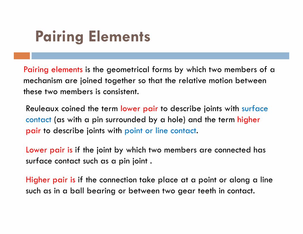
The six Lower Pairs
Lower pairs and Higher pairs


Drawing Kinematic Diagrams

A Mechanism and its Kinematic
Diagram

Determining Degree of Freedom or
Mobility
The concept of degree of freedom (DOF) is fundamentalto both the synthesis and analysis of mechanisms.
Degree of Freedom :Degree of Freedom :
The number of inputs that need to be provided in order tocreate a predictable output;
also:
The number of independent coordinates required todefine its position.

Kinematic chains or mechanisms
may be either open or closed
Open or Closed Mechanism chains
A closed mechanism will have no open attachment
points or nodes and may have one or more degrees of freedom.
An open mechanism of more than one link will always have more than one degree of freedom, thus requiring have more than one degree of freedom, thus requiring as many actuators (motors) as it has DOF.
A common example of an open mechanism is an
industrial robot.
An open kinematic chain of two binary links and one joint is called a dyad. The sets of links shown in Figure b and c are dyads.
Degree of Freedom
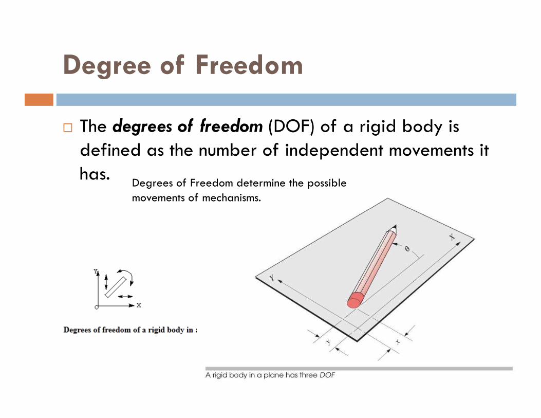
� The degrees of freedom (DOF) of a rigid body is defined as the number of independent movements it has.
there are 3 DOF
Degrees of Freedom determine the possible movements of mechanisms.
there are 3 DOF
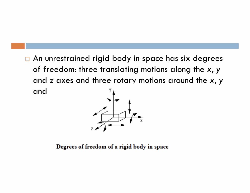
� An unrestrained rigid body in space has six degrees of freedom: three translating motions along the x, yand z axes and three rotary motions around the x, yand z axes respectively.
Degree of Freedom (Mobility) in
Planar Mechanisms
To determine the overall DOF of any mechanism, we must account for the number of links and joints, and for the interactions among them.
Any link in a plane has 3 DOF. Therefore, a system of L unconnected links in the same plane will have 3L
DOF, as shown in Figure a below where the two unconnected links have a total of six DOF.

Kinematic Constraints
� Two or more rigid bodies in space are collectively called a rigid body system. We can hinder the motion of these independent rigid bodies with kinematic constraints.
� Kinematic constraints are constraints between rigid bodies that result in the decrease of the degrees of freedom of rigid body system.

Two unconnected Links
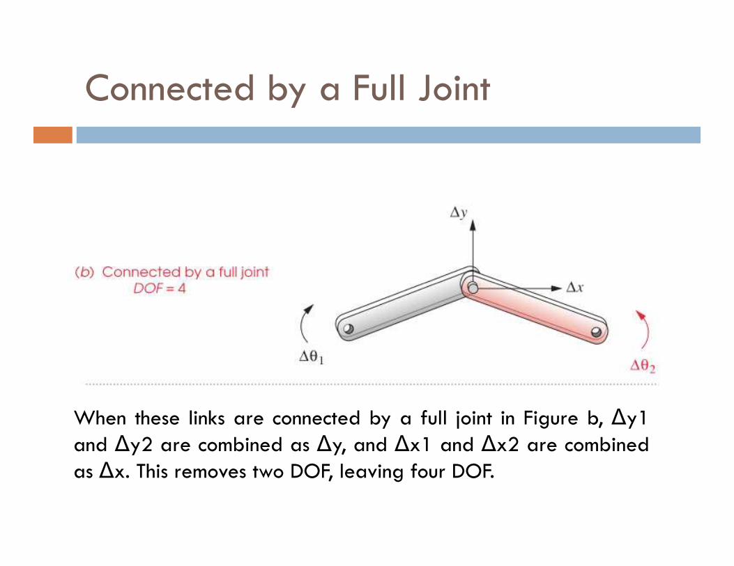
Connected by a Full Joint
When these links are connected by a full joint in Figure b, ∆y1and ∆y2 are combined as ∆y, and ∆x1 and ∆x2 are combinedas ∆x. This removes two DOF, leaving four DOF.

Connected by a roll-slide (half) joint
In Figure c the half joint removes only one DOF from the system(because a half joint has two DOF), leaving the system of two linksconnected by a half joint with a total of five DOF.

Gruebler’s Eqution
In addition, when any link is grounded or attached to the reference frame, all three of its DOF will be removed.
This reasoning leads to Gruebler’s equation:This reasoning leads to Gruebler’s equation:
M = 3L – 2J – 3G
where:
M = degree of freedom or mobility
L = number of links
J = number of joints
G = number of grounded links

Note that in any real mechanism, even if more than one link of thekinematic chain is grounded, the net effect will be to create one larger,higher-order ground link, as there can be only one ground plane. Thus Gis always one, and Gruebler’s equation becomes:
M = 3(L -1) – 2J
The value of J in equations above must reflect the value of all joints in themechanism. That is, half joints count as 1/2 because they only removeone DOF.
It is less confusing if we use Kutzbach’s equation in this form:It is less confusing if we use Kutzbach’s equation in this form:
M = 3(L-1) – 2J1 – J2
where:
M = degree of freedom or mobility
L = number of links
J1 = number of 1 DOF (full) joints
J2 = number of 2 DOF (half) joints

Degree of Freedom (Mobility) in Spatial Mechanisms
The approach used to determine the mobility of a planarmechanism can be easily extended to three dimensions.Each unconnected link in three-space has 6 DOF, and anyone of the six lower pairs can be used to connect them, ascan higher pairs with more freedom.
A one-freedom joint removes 5 DOF, a two-freedom jointA one-freedom joint removes 5 DOF, a two-freedom jointremoves 4 DOF, etc.
Grounding a link removes 6 DOF. This leads to the Kutzbachmobility equation for spatial linkages:
M = 6(L-1) – 5J1 – 4J2 – 3J3 – 2J2 – J5
where the subscript refers to the number of freedoms of the joint.
MECHANISMS AND STRUCTURES
The degree of freedom of an assembly of linkscompletely predicts its character. There are onlythree possibilities.
1. If the DOF is positive, it will be a mechanism, andthe links will have relative motion.the links will have relative motion.
2. If the DOF is exactly zero, then it will be a structure,and no motion is possible.
3. If the DOF is negative, then it is a preloadedstructure, which means that no motion is possible andsome stresses may also be present at the time ofassembly.

Mechanisms, structures, and preloaded structures