2 4.1 Configuring PTZ Settings 4.2 Setting PTZ Presets, Patrols & Patterns Chapter 5 Record...
45
Transcript of 2 4.1 Configuring PTZ Settings 4.2 Setting PTZ Presets, Patrols & Patterns Chapter 5 Record...


www.LaViewSecurity.com2
www.LaViewSecurity.com 1
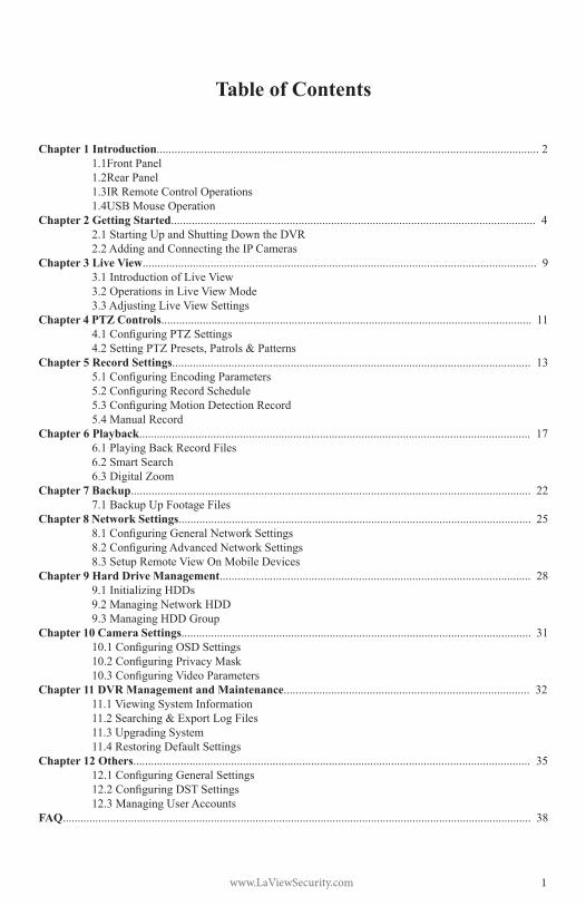
Table of Contents
Chapter 1 Introduction................................................................................................................................. 2 1.1Front Panel 1.2Rear Panel 1.3IR Remote Control Operations 1.4USB Mouse OperationChapter 2 Getting Started........................................................................................................................... 4 2.1 Starting Up and Shutting Down the DVR 2.2 Adding and Connecting the IP CamerasChapter 3 Live View..................................................................................................................................... 9 3.1 Introduction of Live View 3.2 Operations in Live View Mode 3.3 Adjusting Live View SettingsChapter 4 PTZ Controls............................................................................................................................. 11 4.1ConfiguringPTZSettings 4.2SettingPTZPresets,Patrols&PatternsChapter 5 Record Settings......................................................................................................................... 13 5.1ConfiguringEncodingParameters 5.2ConfiguringRecordSchedule 5.3ConfiguringMotionDetectionRecord 5.4 Manual RecordChapter 6 Playback.................................................................................................................................... 17 6.1 Playing Back Record Files 6.2 Smart Search 6.3DigitalZoomChapter 7 Backup....................................................................................................................................... 22 7.1 Backup Up Footage FilesChapter 8 Network Settings....................................................................................................................... 25 8.1ConfiguringGeneralNetworkSettings 8.2ConfiguringAdvancedNetworkSettings 8.3 Setup Remote View On Mobile DevicesChapter 9 Hard Drive Management......................................................................................................... 28 9.1 Initializing HDDs 9.2ManagingNetworkHDD 9.3ManagingHDDGroupChapter 10 Camera Settings...................................................................................................................... 31 10.1ConfiguringOSDSettings 10.2ConfiguringPrivacyMask 10.3ConfiguringVideoParametersChapter 11 DVR Management and Maintenance................................................................................... 32 11.1 Viewing System Information 11.2Searching&ExportLogFiles 11.3 Upgrading System 11.4 Restoring Default SettingsChapter 12 Others...................................................................................................................................... 35 12.1ConfiguringGeneralSettings 12.2ConfiguringDSTSettings 12.3 Managing User AccountsFAQ.............................................................................................................................................................. 38
www.LaViewSecurity.com2
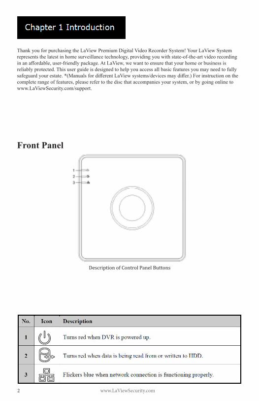
ThankyouforpurchasingtheLaViewPremiumDigitalVideoRecorderSystem!YourLaViewSystemrepresentsthelatestinhomesurveillancetechnology,providingyouwithstate-of-the-artvideorecordinginanaffordable,user-friendlypackage.AtLaView,wewanttoensurethatyourhomeorbusinessisreliablyprotected.Thisuserguideisdesignedtohelpyouaccessallbasicfeaturesyoumayneedtofullysafeguardyourestate.*(ManualsfordifferentLaViewsystems/devicesmaydiffer.)Forinstructiononthecompleterangeoffeatures,pleaserefertothediscthataccompaniesyoursystem,orbygoingonlinetowww.LaViewSecurity.com/support.
Front Panel
Description of Control Panel Buttons
www.LaViewSecurity.com 3
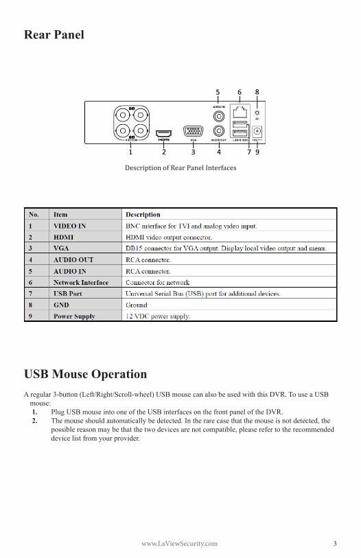
Rear Panel
Description of Rear Panel Interfaces
USB Mouse OperationAregular3-button(Left/Right/Scroll-wheel)USBmousecanalsobeusedwiththisDVR.TouseaUSB
mouse:1. Plug USB mouse into one of the USB interfaces on the front panel of the DVR.2. Themouseshouldautomaticallybedetected.Intherarecasethatthemouseisnotdetected,the
possiblereasonmaybethatthetwodevicesarenotcompatible,pleaserefertotherecommendeddevice list from your provider.
www.LaViewSecurity.com4
Starting Up and Shutting Down the DVRBefore you start:CheckthatthevoltageoftheextrapowersupplyisthesameastheDVR’srequirement,andthegroundconnection is working properly.Starting up the DVR:Steps:
1. Check that the power supply is plugged into an electrical outlet. It is HIGHLYrecommended that an Uninterruptible Power Supply(UPS)beusedinconjunctionwiththedevice.
2. Turnonthepowerswitchontherearpanel.3. Afterstartup,thePowerLEDindicatorturns
on . A splash screen with the status of the HDD appears on the monitor. The row oficons at the bottom of the screen shows the HDD status. ‘X’ means that the HDD is not installed or cannot be detected.
Shutting down the DVRSteps:
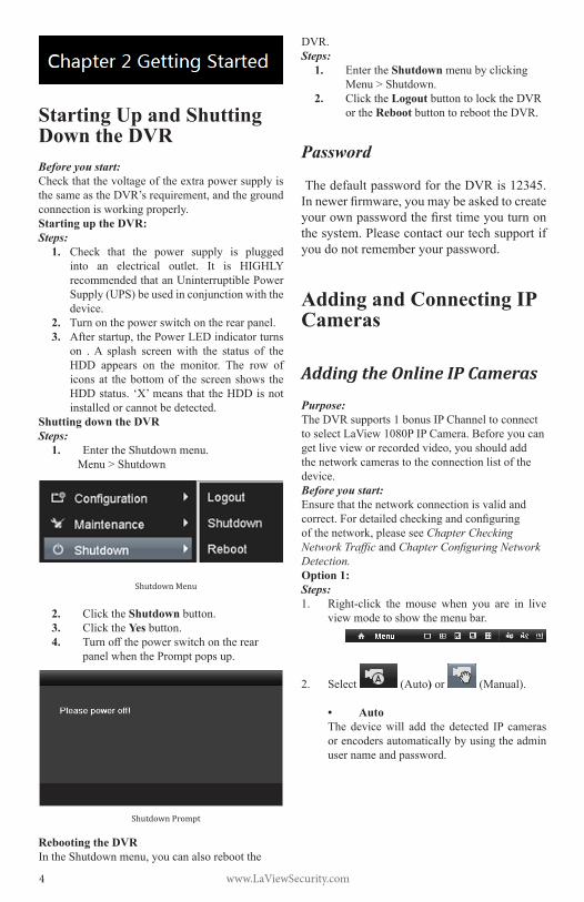
1. EntertheShutdownmenu.Menu > Shutdown
Shutdown Menu
2. Click the Shutdown button.3. Click the Yes button.4. Turnoffthepowerswitchontherear
panel when the Prompt pops up.
Shutdown Prompt
Rebooting the DVRIntheShutdownmenu,youcanalsorebootthe
DVR.Steps:
1. EntertheShutdown menu by clicking Menu > Shutdown.
2. Click the Logout button to lock the DVR or the Reboot button to reboot the DVR.
Password
ThedefaultpasswordfortheDVRis12345.Innewerfirmware,youmaybeaskedtocreateyourownpasswordthefirsttimeyouturnonthe system. Please contact our tech support if you do not remember your password.
Adding and Connecting IP Cameras
Adding the Online IP Cameras
Purpose:TheDVRsupports1bonusIPChanneltoconnectto select LaView 1080P IP Camera. Before you can getlivevieworrecordedvideo,youshouldaddthe network cameras to the connection list of the device.Before you start:Ensurethatthenetworkconnectionisvalidandcorrect.Fordetailedcheckingandconfiguringofthenetwork,pleaseseeChapter Checking Network Traffic and Chapter Configuring Network Detection.Option 1:Steps:1. Right-click the mouse when you are in live
view mode to show the menu bar.
2. Select (Auto) or (Manual).
• AutoThedevicewill add the detected IP camerasor encoders automatically by using the admin user name and password.

www.LaViewSecurity.com 5
Auto Adding IP Camera Interface
Note: If the user name and password are changed, the auto adding of IP camera mayfail. you may add it manually if necessary.• ManualSteps:1. To add online cameras with same
network segment:1) Thedetectedonlinecamerawillbe
listedinthecameralist,asshowninthefigurebelow.
Manual Adding IP Camera Interface
2) Click the button to add the camera.
2. ToaddotherIPcameras:1) Click the Custom Adding button
toseetheAddIPCamera(Custom)interface.
Manual Adding IP Camera Interface
2) You can edit the IP address,protocol, management port,and other information for the IP camera.
3) Click Add to add the camera.
Option 2:Steps:1. EntertheCameraManagementinterface.
Menu> Camera> Camera
Menu
2. To add online cameras with same networksegment:1) Click Search to search for online
cameras.
www.LaViewSecurity.com6
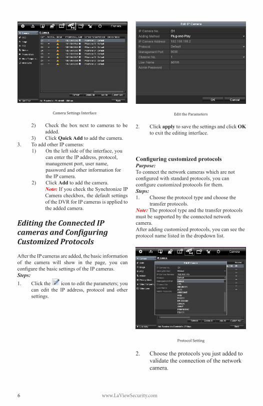
Camera Settings Interface
2) Check the box next to cameras to beadded.
3) Click Quick Add to add the camera.3. ToaddotherIPcameras:
1) Ontheleftsideoftheinterface,youcanentertheIPaddress,protocol,managementport,username,password and other information for the IP camera.
2) Click Add to add the camera.Note: If you check the Synchronize IP Cameracheckbox,thedefaultsettingsof the DVR for IP cameras is applied to the added camera.
Editing the Connected IP cameras and Configuring Customized Protocols
AftertheIPcamerasareadded,thebasicinformationof the camera will show in the page, you canconfigurethebasicsettingsoftheIPcameras.Steps:1. Click the icon to edit the parameters; you
can edit the IP address, protocol and othersettings.
Edit the Parameters
2. Click apply to save the settings and click OK toexittheeditinginterface.
Configuring customized protocolsPurpose: Toconnectthenetworkcameraswhicharenotconfiguredwithstandardprotocols,youcanconfigurecustomizedprotocolsforthem.Steps:1. Choose the protocol type and choose the
transfer protocols.Note: Theprotocoltypeandthetransferprotocolsmust be supported by the connected network camera. Afteraddingcustomizedprotocols,youcanseetheprotocol name listed in the dropdown list.
Protocol Setting
2. Choose the protocols you just added to validate the connection of the network camera.

www.LaViewSecurity.com 7
Editing IP Cameras connected to the PoE interfaces (applicable models only)ThePoEinterfaceenablestheDVRsystemtopasselectricalpoweranddata,throughEthernetcablingto the connected network cameras.LaViewDVRsprovidesPoE interfaceswhich canconnect to network cameras directly; and if you dont use thePoE interface,youcanalsoconnect to theonlinenetworkcameras.ThePoEinterfacesupportsthePlug-and-Playfunction.Example:For LaView DVRs, when you want to connect 1online camera and connect 3 network cameras via PoEinterfaces,youmustdisable1PoEinterfaceinthe Edit IP camera panel.To add Cameras for DVR supporting PoE function:Before you start:Connect the network cameras using the PoEinterfaces.Steps: 1. EntertheCameraManagementinterface.
Main menu> Camera> CameraTheconnectedcamerasarelisted.
List of Connected Cameras
Edit IP Camera Interface
Note: Plug-and-PlaymeansthatthecameraisconnectedtothePoEinterface.Theparametersofthecameracan’tbeeditedhere.TheIPaddressofthecameracanonlybeeditedintheNetworkConfigurationinterface,seeChapter Configuring General Settings for detailed information.
Editing IP cameras connected to the built-in switch network interfaces (applicable models only) In LaView DVRs, the extra network interfacesprovide a built-in switch with plug-and-playfunction.Example:When you want to connect 2 online cameras and 6 networkcamerasviabuilt-inswitchinterfaces,youmustdisable2built-inswitchinterfacesintheEdit IP camera panel.To add Cameras for DVR via built-in switch interfaces:Before you start:Connectthenetworkcamerasviathebuilt-inswitchinterfaces.Steps:1. EntertheCameraManagementinterface.
Main menu> Camera> CameraTheconnectedcamerasshouldbelisted.

www.LaViewSecurity.com8
List of Connected Cameras
Note: The cameras connected to the built-in switch interface cannot be deleted in this menu.
2. Click the Edit button.
Edit IP Camera Interface
Note: Plug-and-Playmeans that the camerais connected to the switch interface. Theparameters of the camera can’t be edited here.TheIPaddressofthecameracanonlybe edited in the Network Configurationinterface.
www.LaViewSecurity.com 9
Introduction of Live ViewLive view shows you the video captured by each camerainrealtime.TheDVRautomaticallyentersLive View mode when powered on.
Live View IconsIntheliveviewmode,thereareiconsatthetoprightofthescreen,showingthestatusofeachchannel,sothatyoucanseewhetherthechannelisrecording,orwhether there are alarms are being triggered.
Operations in Live View Mode
Inliveviewmode,therearemanyfunctionsprovided.Thefunctionsarelistedbelow.
• Single Screen: Showing only one screen on the monitor.
• Multi-screen: Showing multiple screens on the monitor simultaneously.
• Auto-switch:Thescreenisautoswitchedtothenextone.Youmustsetthedwelltimeforeachscreenontheconfigurationmenubeforeenablingauto-switch.Menu>Configuration>LiveView>General.
• Start Recording: Normalrecordandmotiondetection record are supported.
• Output Mode: Select the output mode to Standard,Bright,GentleorVivid.
• All-day Playback: Playback the recorded videos for the selected day.
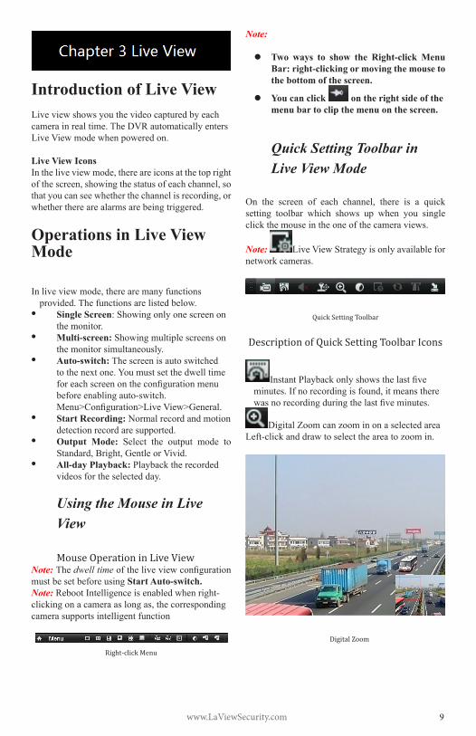
Using the Mouse in Live View Mouse Operation in Live View
Note: Thedwell timeoftheliveviewconfigurationmust be set before using Start Auto-switch.Note: RebootIntelligenceisenabledwhenright-clickingonacameraaslongas,thecorrespondingcamera supports intelligent function
Right-click Menu
Note:
Two ways to show the Right-click Menu Bar: right-clicking or moving the mouse to the bottom of the screen.
You can click on the right side of the menu bar to clip the menu on the screen.
Quick Setting Toolbar in Live View Mode
On the screen of each channel, there is a quicksetting toolbar which shows up when you single click the mouse in the one of the camera views.
Note: Live View Strategy is only available for network cameras.
Quick Setting Toolbar
Description of Quick Setting Toolbar Icons
InstantPlaybackonlyshowsthelastfiveminutes.Ifnorecordingisfound,itmeanstherewasnorecordingduringthelastfiveminutes.
DigitalZoomcanzoominonaselectedareaLeft-clickanddrawtoselecttheareatozoomin.
Digital Zoom
www.LaViewSecurity.com10
Adjusting Live View SettingsPurpose:Live View settings can be customized according to yourneeds.Youcanconfiguretheoutputinterface,dwelltimeforeachchannel,mute/volumeforaudio,thescreennumberforeachchannel,etc.Steps:
1. EntertheLiveViewSettingsinterface.Menu>Configuration>LiveView
Live View-General
Thesettingsavailableinthismenuinclude:• Video Output Interface: Designates the
outputtobeusedoptionsincludeVGA/HDMI.
• Live View Mode: Designates the display mode to be used for Live View.
• Dwell Time: Thetimeinsecondsbetweenswitchingofchannelswhenauto-switchisenabled in Live View.
• Enable Audio Output: Enables/disablesaudio output for the selected video output.
• Event Output: Designates the output where to show event video.
• Full Screen Monitoring Dwell Time: Thetime in seconds to show an event on screen.
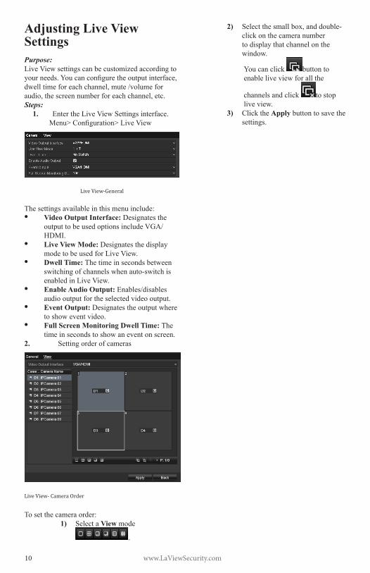
2. Setting order of cameras
Live View- Camera Order
Tosetthecameraorder:1) Select a View mode
.
2) Selectthesmallbox,anddouble-click on the camera number to display that channel on the window.
Youcanclick button to enable live view for all the
channels and click to stop live view.
3) Click the Apply button to save the settings.

www.LaViewSecurity.com 11
Configuring PTZ SettingsPurpose:FollowtheproceduretosettheparametersforPTZ.TheconfiguringofthePTZparametersmustbedonebeforeyoucancontrolthePTZcamera.Steps:
1. EnterthePTZSettingsinterface.Menu>Camera>PTZ
PTZ- General
2. Choose the camera in the Camera dropdown list.
3. EntertheparametersofthePTZcamera.Note: AlltheparametersshouldbeinthePTZ
camera parameters section of the camera manual.Example:IfthePTZcamerausestheprotocolofDRAGON,youshouldselectDRAGONinthePTZProtocolfield.
4. Click Apply button to save the settings.
Setting PTZ Presets, Patrols & Patterns
Before you start:Pleasemakesurethatthepresets,patrolsandpatternsarebesupportedbyPTZprotocols.
Customizing PresetsPurpose:FollowthestepstosetthePresetlocation,whichiswhereyouwantthePTZcameratopointwhenanevent takes place.Steps:
1. EnterthePTZControlinterface.Menu>Camera>PTZ>MoreSettings
PTZ-MoreSettings
2. Use the directional button to wheel the camera to the location that you want to as preset.3. ClicktheroundiconnexttoSave Preset.4. Click the preset number to save the preset.Repeatthesteps2-4tosavemorepresets.Ifthenumber of the presets you want to save is more than17,youcanclick[…]andchoosetheavailablenumbers.
More Presets
Calling Presets
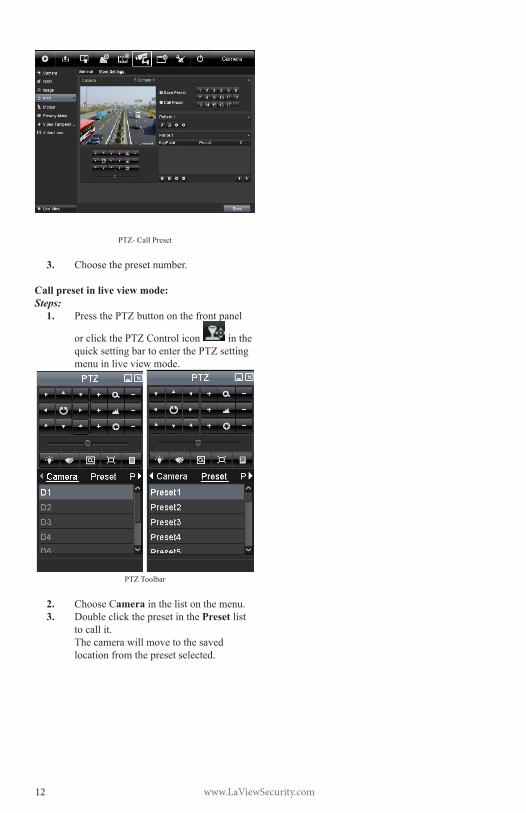
Purpose:Thisfeatureenablesthecameratopointtoaspecifiedpositionsuchasawindowwhenapresetis needed.
Call preset in the PTZ setting interface:Steps:
1. EnterthePTZControlinterface.Menu>Camera>PTZ>MoreSettings
2. Check the round icon of Call Preset.
www.LaViewSecurity.com12
PTZ-CallPreset
3. Choose the preset number.
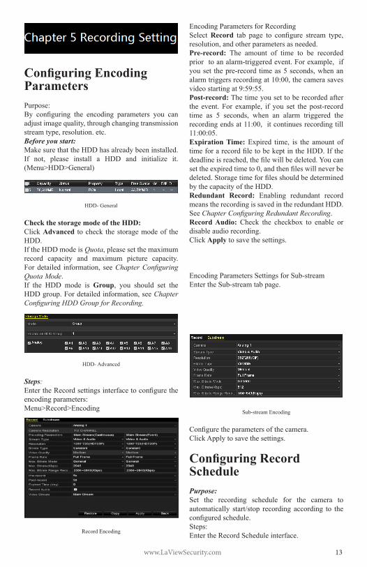
Call preset in live view mode:Steps:
1. PressthePTZbuttononthefrontpanel
orclickthePTZControlicon in the quicksettingbartoenterthePTZsettingmenu in live view mode.
PTZToolbar
2. Choose Camera in the list on the menu.3. Double click the preset in the Preset list
to call it. Thecamerawillmovetothesavedlocation from the preset selected.
www.LaViewSecurity.com 13
Configuring Encoding ParametersPurpose: By configuring the encoding parameters you canadjustimagequality,throughchangingtransmissionstreamtype,resolution.etc.Before you start:Make sure that the HDD has already been installed. If not, please install a HDD and initialize it.(Menu>HDD>General)
HDD-General
Check the storage mode of the HDD:Click Advanced to check the storage mode of the HDD. If the HDD mode is Quota,pleasesetthemaximumrecord capacity and maximum picture capacity.Fordetailed information, seeChapter Configuring Quota Mode.If the HDD mode is Group, you should set theHDDgroup.Fordetailedinformation,seeChapter Configuring HDD Group for Recording.
HDD-Advanced
Steps:EntertheRecordsettingsinterfacetoconfiguretheencoding parameters:Menu>Record>Encoding
RecordEncoding
EncodingParametersforRecordingSelect Record tab page to configure stream type,resolution,andotherparametersasneeded.Pre-record: The amount of time to be recordedpriortoanalarm-triggeredevent.Forexample,ifyouset thepre-record timeas5seconds,whenanalarmtriggersrecordingat10:00,thecamerasavesvideo starting at 9:59:55. Post-record:Thetimeyousettoberecordedafterthe event. For example, if you set the post-recordtime as 5 seconds, when an alarm triggered therecordingendsat11:00,itcontinuesrecordingtill11:00:05.Expiration Time: Expired time, is the amount oftimeforarecordfiletobekeptintheHDD.Ifthedeadlineisreached,thefilewillbedeleted.Youcansettheexpiredtimeto0,andthenfileswillneverbedeleted.Storagetimeforfilesshouldbedeterminedby the capacity of the HDD.Redundant Record: Enabling redundant recordmeans the recording is saved in the redundant HDD. See Chapter Configuring Redundant Recording.Record Audio: Check the checkbox to enable ordisable audio recording.Click Apply to save the settings.
EncodingParametersSettingsforSub-streamEntertheSub-streamtabpage.
Sub-streamEncoding
Configuretheparametersofthecamera.Click Apply to save the settings.
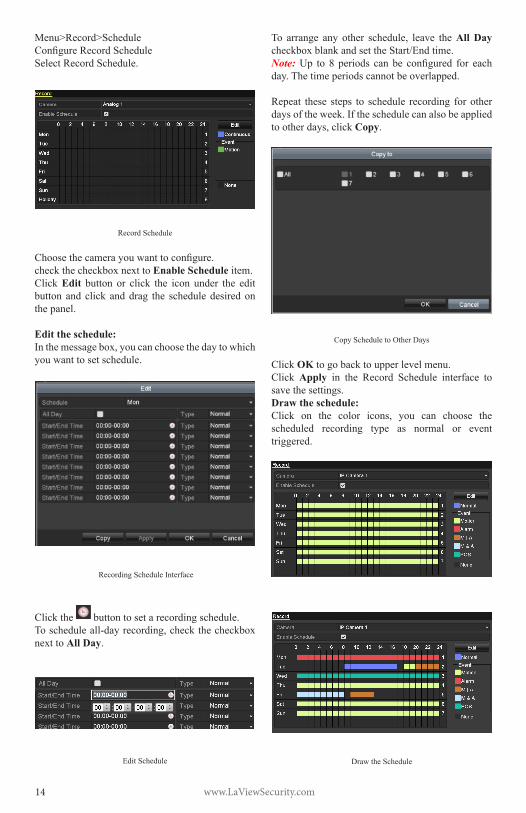
Configuring Record SchedulePurpose: Set the recording schedule for the camera to automatically start/stop recording according to theconfiguredschedule.Steps:EntertheRecordScheduleinterface.
www.LaViewSecurity.com14
Menu>Record>ScheduleConfigureRecordScheduleSelect Record Schedule.
Record Schedule
Choosethecamerayouwanttoconfigure.checkthecheckboxnexttoEnable Schedule item.Click Edit button or click the icon under the edit button and click and drag the schedule desired on the panel.
Edit the schedule:Inthemessagebox,youcanchoosethedaytowhichyou want to set schedule.
Recording Schedule Interface
Click the button to set a recording schedule.Toscheduleall-dayrecording,checkthecheckboxnexttoAll Day.
EditSchedule
To arrange any other schedule, leave theAll Day checkboxblankandsettheStart/Endtime.Note: Up to 8 periods can be configured for eachday.Thetimeperiodscannotbeoverlapped.
Repeat these steps to schedule recording for other days of the week. If the schedule can also be applied tootherdays,click Copy.
Copy Schedule to Other Days
Click OK to go back to upper level menu.Click Apply in the Record Schedule interface to save the settings.Draw the schedule:Click on the color icons, you can choose thescheduled recording type as normal or event triggered.
Draw the Schedule

www.LaViewSecurity.com 15
Descriptions of the scheduled recording icons are showninthefigurebelow.
Descriptions of the scheduled recording icons
Click the Apply button to validate the settings.Ifyouwishtousethesesettingsforotherchannels,click Copy, thenchoosethechannel towhichyouwant to copy the settings.
Copy Schedule to Other Channels
Configuring Motion Detection RecordPurpose: Follow these steps to set the motion detection parameters. In live view mode, when a motiondetection event takes place, theDVR can analyzeit and carry out a variety of actions to handle it. Enabling motion detection function can triggercertain channels to start recording, full screenmonitoring, audiowarning, notify the surveillancecenter etc.
Steps:EntertheMotionDetectioninterface.Menu>Camera>Motion
Motion Detection
ConfigureMotionDetection:Choosecamerayouwanttoconfigure.Check the checkbox next to Enable Motion Detection.Crop the area for motion detection by mouse. If you want to set motion detection for the area shot by the camera,clickFull Screen.Tostartover,click Clear.
MotionDetection-Grid
Click Setting to select channels that will link to the motion detection trigger.
Motion Detection Settings
Select the channels for which you want the motion detection event to trigger recording.Click Apply to save the settings.Click OK to go back to menu.ExittheMotionDetectionmenu.Fordetailedinformationonscheduleconfiguration,

www.LaViewSecurity.com16
see Chapter Configuring Record Schedule.
Manual Record
Purpose: Follow the steps to set parameters for manual recording.
Steps:EntertheManualsettingsinterface.Menu> ManualOr press the REC button on the remote control.
Manual Record
EnablingManualRecord:Select Record on the left bar.Nexttothecameranumber,change to .
Disabling manual record:Nexttothecameranumber,change to .
Note: After rebooting, allmanual records enabledare canceled.
Startall-daycontinuousrecordingorall-daymotiondetection recording of all channels:Click for or .
Continuous Recording
Motion Detection Recording
Click to enable all-day continuousrecordingorall-daymotiondetectionrecordingonall channels.

www.LaViewSecurity.com 17
Playing Back Record Files
Playing Back by Channel
Purpose:Play back the recorded video files of a specificchannel in live view mode. Channel switch is supported.OPTION 1:Choose a channel in live view mode using the mouse
and click the button in the quick setting toolbar.Note: Ininstantplaybackmode,onlyfilesrecordedduringthelastfiveminutesonthischannelwillbeplayed back.
Instant Playback Interface
OPTION 2:EnterthePlaybackinterface.Mouse: right click a channel in live view mode and
select from the menu.
Right-clickMenuunderLiveView
Front Panel: press PLAY button to play back recordedfilesfromthechannelundersingle-screenlive view mode.Whenonmulti-screenliveviewmode,therecordedfilesfromthetop-leftchannelwillbeplayedback.Note: During playback process, pressing thenumerical buttons will switch playback to the corresponding channels.Playback management:ThetoolbaronthebottomofthePlaybackinterfacecan be used to control playing progress.
Playback Interface
Clickonmultiplechannel(s)toexecutesimultaneousplayback.
ToolbarofPlayback
Note:
indicatesthestart/endtimeofrecording.DetailedExplanationofPlaybackToolbar
Note: Playback progress bar: Use the mouse to click on point in the progress bar or drag the progress bar tolocatespecificframes.
Playing Back by Time
Purpose:Play back video files recorded in specified timeduration.Multi-channelsimultaneousplaybackandchannel switch are supported.Steps:Enterplaybackinterface.Menu>PlaybackCheck off channel(s) in the channel list and thendouble-clicktoselectadateonthecalendar.

www.LaViewSecurity.com18
Playback Calendar
Note:Ifacamerahas recordings fromthatday, the icon
in the calendar is displayed as . Otherwise it is displayed as . The selecteddate is surrounded
byawhiterectangle,asin .In the Playback interface:ThetoolbaratthebottomofthePlaybackinterfacecan be used to control playing progress.
InterfaceofPlaybackbyTime
ToolbarofPlaybackbyTime
Note: The
indicatesthestart/endtimeoftherecording.
Detailed Explanation of Playback-by-timeInterfaceNote:Playback progress bar: Use the mouse to click on any point in the progress bar or drag the progress bar tolocatespecificframes.
Playing Back by Event SearchPurpose:Playbackspecificfilesononeorseveralchannelsby restricting event type (e.g. alarm input and motiondetection).Steps:EnterthePlaybackinterface.Menu>PlaybackSelect Eventinthedrop-downlistonthetop-left.Select Alarm Input or Motion as the event type and settheStarttimeandEndtime.
Alarm Input Search Interface
Motion Search Interface

www.LaViewSecurity.com 19
Click the Search button to get search results from theinformationprovided.Refertoright-sidebarforresults.
SearchResultBar(AlarmInandMotion)
Click buttontoplaybackthefile.Note:Pre-playandpost-playcanbeconfigured.If the event is set to trigger recording on multiple
channels, clicking the will activate the Synch Playback interface.Youcanselectwhichchannelsto play back synchronously.Click the Back button to go back to the search interface.Playback interface:ThetoolbaratthebottomofthePlaybackinterfacecan be used to control playing progress.
InterfaceofPlaybackbyEvent
ToolbarofPlaybackbyEvent
Detailed Explanation of Playback-by-EventToolbarNote:Playback progress bar: Use the mouse to click on any point in the progress bar or drag the progress bar tolocatespecificframes.
Smart Search
Purpose:In order to locate motion detection events easily in theplaybackprogressbar,youcananalyzeacertainarea/scenetogetalloftherelatedmotiondetectionevents that occurred in the area.Note: Thesmartsearchfunctionmayvaryaccordingto the camera connected to the DVR.Before you start:Loginthenetworkcamerausingyourwebbrowser,and enable the Dynamic Analysis for Motion by checkingthecheckboxnexttoit.Enterthemotiondetectionconfigurationinterface:Configuration>Advanced Configuration> Events>Motion Detection.
www.LaViewSecurity.com20
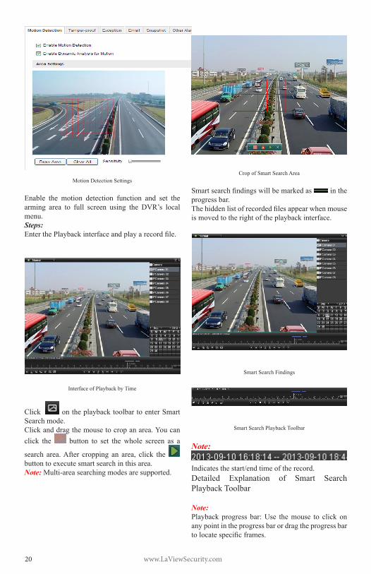
Motion Detection Settings
Enable the motion detection function and set thearming area to full screen using the DVR’s local menu. Steps:EnterthePlaybackinterfaceandplayarecordfile.
InterfaceofPlaybackbyTime
Click on the playback toolbar to enter Smart Search mode.Clickanddragthemousetocropanarea.Youcanclick the button to set the whole screen as a
search area.After cropping an area, click the buttontoexecutesmartsearchinthisarea.Note: Multi-areasearchingmodesaresupported.
Crop of Smart Search Area
Smartsearchfindingswillbemarkedas in the progress bar.Thehiddenlistofrecordedfilesappearwhenmouseis moved to the right of the playback interface.
Smart Search Findings
SmartSearchPlaybackToolbar
Note:
Indicatesthestart/endtimeoftherecord.Detailed Explanation of Smart SearchPlaybackToolbar
Note:Playback progress bar: Use the mouse to click on any point in the progress bar or drag the progress bar tolocatespecificframes.
www.LaViewSecurity.com 21
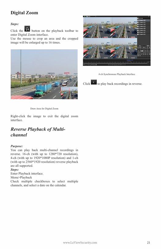
Digital Zoom
Steps:
Click the button on the playback toolbar to enterDigitalZoominterface.Use the mouse to crop an area and the cropped image will be enlarged up to 16 times.
DrawAreaforDigitalZoom
Right-click the image to exit the digital zoominterface.
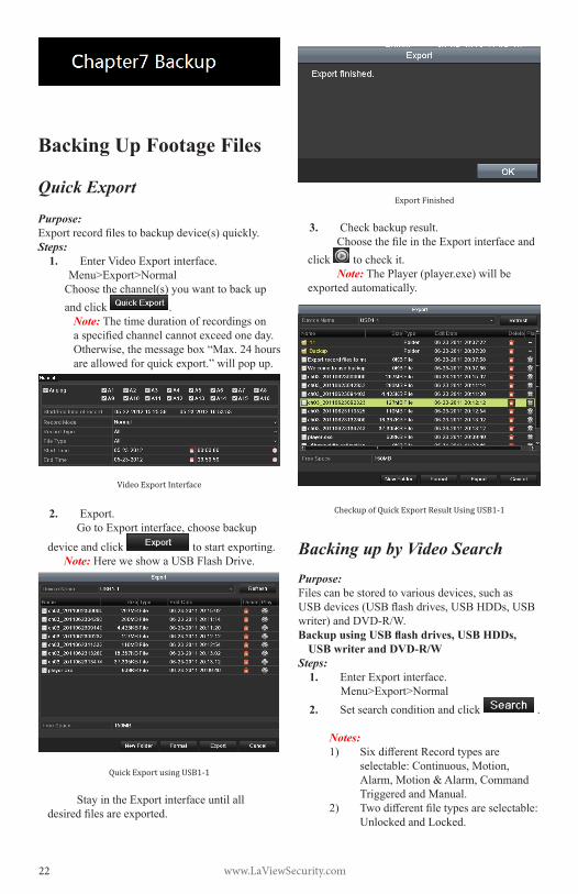
Reverse Playback of Multi-channel
Purpose:You can play back multi-channel recordings inreverse. 16-ch (with up to 1280*720 resolution),4-ch (withup to1920*1080P resolution)and1-ch(withupto2560*1920resolution)reverseplaybackare all supported. Steps:EnterPlaybackinterface.Menu>PlaybackCheck multiple checkboxes to select multiplechannels,andselectadateonthecalendar.
4-chSynchronousPlaybackInterface
Click to play back recordings in reverse.
www.LaViewSecurity.com22
Backing Up Footage Files
Quick Export
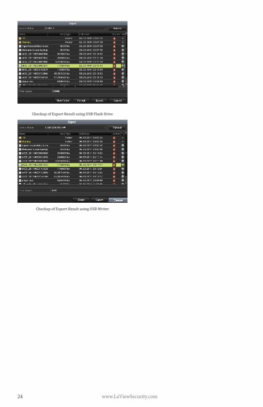
Purpose:Exportrecordfilestobackupdevice(s)quickly.Steps:
1. EnterVideoExportinterface.Menu>Export>NormalChoosethechannel(s)youwanttobackupand click .
Note:Thetimedurationofrecordingsonaspecifiedchannelcannotexceedoneday.Otherwise,themessagebox“Max.24hoursareallowedforquickexport.”willpopup.
Video Export Interface
2. Export.GotoExportinterface,choosebackup
device and click tostartexporting.Note: Here we show a USB Flash Drive.
Quick Export using USB1-1
StayintheExportinterfaceuntilalldesiredfilesareexported.
Export Finished
3. Check backup result.ChoosethefileintheExportinterfaceand
click to check it.Note: ThePlayer(player.exe)willbe
exportedautomatically.
Checkup of Quick Export Result Using USB1-1
Backing up by Video SearchPurpose:Filescanbestoredtovariousdevices,suchasUSBdevices(USBflashdrives,USBHDDs,USBwriter)andDVD-R/W.Backup using USB flash drives, USB HDDs,
USB writer and DVD-R/WSteps:
1. EnterExportinterface.Menu>Export>Normal
2. Set search condition and click .
Notes: 1) SixdifferentRecordtypesare
selectable:Continuous,Motion,Alarm,Motion&Alarm,CommandTriggeredandManual.
2) Twodifferentfiletypesareselectable:Unlocked and Locked.

www.LaViewSecurity.com 23
Normal Video Search for Backup
3. Selectthefilesyouwanttobackup.Click toplaythefileifyouwantto
check it.Checkthecheckboxnexttothefilesyou
want to back up.Note: Thesizeofcurrentlyselectedfilesis
displayedinthelower-leftcornerofthewindow.
Result of Normal Video Search for Backup
4. Export.
Click and start backup.Note: If the inserted device is not
recognized:
• Click .• Reconnect device.• Check for compatibility from vendor.YoucanalsoformatUSBflashdrives
or USB HDDs via the device. USB writer and DVD-R/Wcannotbeformatted.
Export by Normal Video Search using USB Flash Drive
Export by Normal Video Search using USB Writer
StayintheExportinterfaceuntilallfilesareexported.Amessageboxsaying“Exportfinished”will signify the process is complete.
Export Finished
5. Check backup result.ChoosethefileinExportinterfaceand
click to check it.Note: ThePlayer(player.exe)willbe
exportedautomatically.
www.LaViewSecurity.com24
Checkup of Export Result using USB Flash Drive
Checkup of Export Result using USB Writer
www.LaViewSecurity.com 25
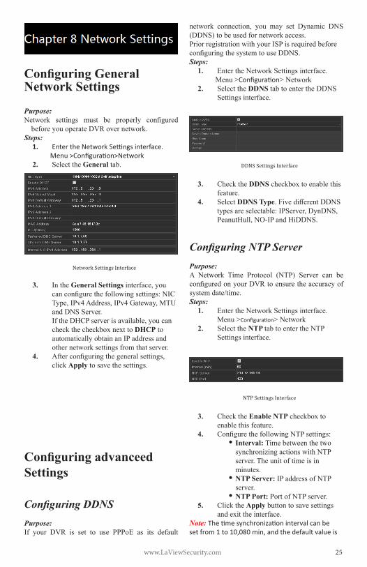
Configuring General Network Settings
Purpose:Network settings must be properly configured
before you operate DVR over network.Steps:
1. Enter the Network Settings interface.Menu >Configuration>Network
2. Select the General tab.
Network Settings Interface
3. In the General Settings interface,youcanconfigurethefollowingsettings:NICType,IPv4Address,IPv4Gateway,MTUandDNSServer.IftheDHCPserverisavailable,youcancheckthecheckboxnexttoDHCP to automatically obtain an IP address and other network settings from that server.
4. Afterconfiguringthegeneralsettings,click Apply to save the settings.
Configuring advanceed Settings
Configuring DDNSPurpose:If your DVR is set to use PPPoE as its default
network connection, you may set Dynamic DNS(DDNS)tobeusedfornetworkaccess.Prior registration with your ISP is required before configuringthesystemtouseDDNS.Steps:
1. EntertheNetworkSettingsinterface.Menu >Configuration>Network
2. Select the DDNS tabtoentertheDDNSSettings interface.
DDNS Settings Interface
3. Check the DDNS checkboxtoenablethisfeature.
4. Select DDNS Type.FivedifferentDDNStypesareselectable:IPServer,DynDNS,PeanutHull,NO-IPandHiDDNS.
Configuring NTP Server
Purpose:A Network Time Protocol (NTP) Server can beconfiguredonyourDVRtoensuretheaccuracyofsystemdate/time.Steps:
1. EntertheNetworkSettingsinterface.Menu >Configuration>Network
2. Select the NTP tabtoentertheNTPSettings interface.
NTP Settings Interface
3. Check the Enable NTPcheckboxtoenable this feature.
4. ConfigurethefollowingNTPsettings:• Interval: TimebetweenthetwosynchronizingactionswithNTPserver.Theunitoftimeisinminutes.
• NTP Server: IPaddressofNTPserver.
• NTP Port: PortofNTPserver.5. Click the Apply button to save settings
andexittheinterface.Note: The time synchronization interval can be set from 1 to 10,080 min, and the default value is

www.LaViewSecurity.com26
60min. If the DVR is connected to a public network, you should use a NTP server that has a time synchronization function, such as the server at the National Time Center (IP Address: 210.72.145.44). If the DVR is set up in a customized network, NTP software can be used to establish a NTP server used for time synchronization.
Configuring RTSPPurpose:The RTSP (Real Time Streaming Protocol) isa network control protocol designed for use in entertainment and communications systems to control streaming media servers.Steps:
1. EntertheNetworkSettingsmenuMenu >Configuration>Network
2. Select the More Settings tab to enter the More Settings menu
RTSP Settings Interface
3. EntertheRTSPportinthetextfieldnextto RTSP Service Port.ThedefaultRTSPportis554,andyoucanchangeitaccordingly.
4. Click Apply button to save settings and exitthemenu.
Configuring Server and HTTP PortsPurpose:Youcanchange the server andHTTPports in theNetworkSettingsmenu.Thedefault serverport is8000andthedefaultHTTPportis80.Steps:
1. EntertheNetworkSettingsinterface.Menu>Configuration>Network
2. Select the More Settings tab to enter the More Settings interface.
More Settings Interface
3. EntertheServerPortandHTTPPortinthetextfields.ThedefaultServerPortis8000andtheHTTPPortis80,andyoucanchangethemaccordingtodifferentrequirements.
4. Click Apply button to save settigns and exittheinterface.
Note: The Server Port should be set to the range of 2000-65535 and is used for remote client software access. The HTTP port is used for remote IE access.
Configuring EmailPurpose:Thesystemcanbeconfiguredtosendanemailnotificationtodesignatedusersif,analarmmotionevent is detected or if the administrator password is changed.
BeforeconfiguringtheemailSettings,theDVRmustbeconnectedtoalocalareanetwork(LAN)thatmaintainsanSMTPmailserver.Thenetworkmust also be connected to either an intranet or the Internetdependingonthelocationofthee-mailaccountstowhichyouwanttosendnotifications.Steps:1. EntertheNetworkSettingsinterface.
Menu>Configuration>Network2. Set the IPv4 Address, IPv4 Subnet Mask,
IPv4GatewayandthePreferredDNSServerintheNetworkSettingsmenu.
3. Click the Apply button to save the settings.1. Select the Email tabtoentertheEmail
Settings interface.
Email Settings Interface
2. Configurethefollowingsettings:Server Authentication (optional): Checkthecheckboxtoenabletheserverauthentication feature.User Name:Theuseraccountofsender’semailforSMTPserverauthentication.Password:Thepasswordofsender’semailforSMTPserverauthentication.SMTP Server: TheSMTPServerIPaddress
www.LaViewSecurity.com 27
orhostname(e.g.,smtp.263xmail.com).SMTP Port No.: TheSMTPport.ThedefaultTCP/IPportusedforSMTPis25.Enable SSL (optional):ClickthecheckboxtoenableSSLifrequiredbytheSMTPserver.Sender: Thenameofsender.Sender’s Address: Theemailaddressofsender.Receivers: Select the receiver. Up to 3 receiverscanbeconfigured.Receiver: Thenameofusertobenotified.Receiver’s Address:Theemailaddressofusertobenotified.Attached Pictures: CheckthecheckboxnexttoEnable Attached Picture if you want to send emails with attached alarm sceneimages.Theintervalisthetimebeforeanotheralarmsceneimageissent.YoucanalsosetSMTPportandenableSSLhere.Interval:Theintervalreferstothetimebetween two alam scene pictures.E-mail Test: Sends a test message to verify thattheSMTPservercanbereached.
3. Click the Apply button to save settings.4. YoucanclickTest button to test whether
your settings work. An Attention message boxwillpopup.Referto0.
Remote ViewingPurpose:You can view both the live and recorded footagefromyourmobiledeviceslikesmartphones,tabletsor laptops.Steps:
1.Connect the DVR to your router.2.Find out the Local IP address of the DVR in your Local Area Network (i.e.:192.168.x.x,10.0.0.x)3.Inyournetworkroutersettinginterface,completethePortForwardingoftheHTTPPort(Default:80),SERVERPort(Default:8000)andRTSPPort (Default:8554) forthe IP address of the DVR.
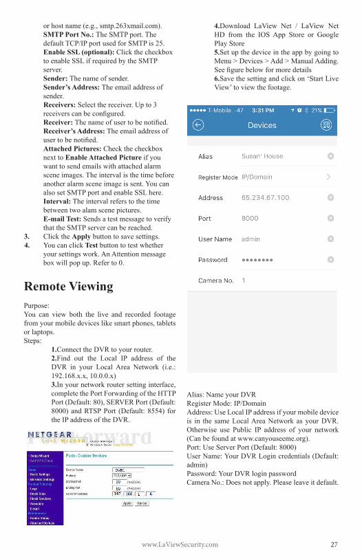
4.Download LaView Net / LaView NetHD from the IOSApp Store or GooglePlay Store5.Set up the device in the app by going to Menu > Devices > Add > Manual Adding. Seefigurebelowformoredetails6.Save the setting and click on ‘Start Live View’ to view the footage.
Alias:NameyourDVRRegisterMode:IP/DomainAddress: Use Local IP address if your mobile device is in the sameLocalAreaNetwork asyourDVR.Otherwise use Public IP address of your network (Canbefoundatwww.canyouseeme.org).Port:UseServerPort(Default:8000)UserName:YourDVRLogincredentials(Default:admin)Password:YourDVRloginpasswordCameraNo.:Doesnotapply.Pleaseleaveitdefault.

www.LaViewSecurity.com28
Initializing HDDsPurpose:Anewlyinstalledharddiskdrive(HDD)mustbe
initialized before it can be used with your DVR.Steps:
1. EntertheHDDInformationinterface.Menu>HDD>General
HDD Information Interface
2. Select HDD to be initialized.3. Click the Init button.
Confirm Initialization
4. Click the OK button to start initialization.
Status Changes to Formatting
5. AftertheHDDhasbeeninitialized,thestatus of the HDD will change from Uninitialized to Normal.
HDD Status Changes to Normal
Note: Initializing the HDD will erase all data on it.
Managing Network HDDPurpose:YoucanaddtheallocatedNASordiskofIPSANtoyourDVR,anduseitasanetworkHDD.
Steps:1. EntertheHDDInformationinterface.
Menu>HDD>General2. Click the Add button to enter the Add
NetHDDinterface.
HDD Information Interface
3. AddtheallocatedNetHDD.4. SelectthetypeaseitherNASorIPSAN.5. ConfiguretheNASorIPSANsettings.
• Add NAS disk:1)EntertheNetHDDIPaddressinthetextfield.
2)EntertheNetHDDDirectoryinthetextfield.
3)Click the OK button to add the configuredNASdisk.
Note: Upto8NASdiskscanbeadded.
www.LaViewSecurity.com 29
Add NAS Disk
• Add IP SAN:1) EntertheNetHDDIPaddressin
thetextfield.2) Click the Search button to view
availableIPSANdisks.3) SelecttheIPSANdiskfromthe
list shown.4) Click the OK button to add the
selectedIPSANdisk.Note: Only1IPSANdiskcanbeadded.
AddIP SAN Disk
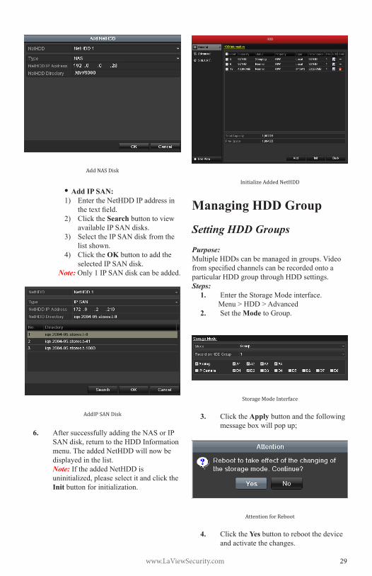
6. AftersuccessfullyaddingtheNASorIPSANdisk,returntotheHDDInformationmenu.TheaddedNetHDDwillnowbedisplayed in the list.Note: IftheaddedNetHDDisuninitialized,pleaseselectitandclicktheInit button for initialization.
Initialize Added NetHDD
Managing HDD Group
Setting HDD Groups
Purpose:Multiple HDDs can be managed in groups. Video fromspecifiedchannelscanberecordedontoaparticular HDD group through HDD settings.Steps:
1. EntertheStorageModeinterface.Menu > HDD > Advanced
2. Set the ModetoGroup.
Storage Mode Interface
3. Click the Apply button and the following messageboxwillpopup;
Attention for Reboot
4. Click the Yes button to reboot the device and activate the changes.
www.LaViewSecurity.com30
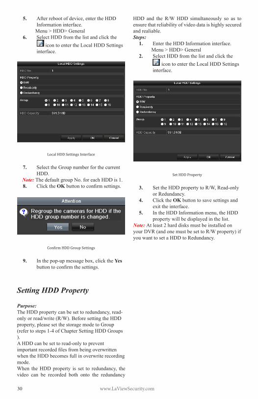
5. Afterrebootofdevice,entertheHDDInformation interface.Menu>HDD>General
6. Select HDD from the list and click the icon to enter the Local HDD Settings
interface.
Local HDD Settings Interface
7. SelecttheGroupnumberforthecurrentHDD.
Note: ThedefaultgroupNo.foreachHDDis1.8. Click the OKbuttontoconfirmsettings.
Confirm HDD Group Settings
9. Inthepop-upmessagebox,clicktheYes buttontoconfirmthesettings.
Setting HDD Property
Purpose:TheHDDpropertycanbesettoredundancy,read-onlyorread/write(R/W).BeforesettingtheHDDproperty,pleasesetthestoragemodetoGroup(refertosteps1-4ofChapterSettingHDDGroups).AHDDcanbesettoread-onlytopreventimportantrecordedfilesfrombeingoverwrittenwhen the HDD becomes full in overwrite recording mode.When theHDDproperty is set to redundancy, thevideo can be recorded both onto the redundancy
HDD and the R/WHDD simultaneously so as toensure that reliability of video data is highly secured and realiable.Steps:
1. EntertheHDDInformationinterface.Menu>HDD>General
2. Select HDD from the list and click the icon to enter the Local HDD Settings
interface.
Set HDD Property
3. SettheHDDpropertytoR/W,Read-onlyor Redundancy.
4. Click the OK button to save settings and exittheinterface.
5. IntheHDDInformationmenu,theHDDproperty will be displayed in the list.
Note: At least 2 hard disks must be installed on yourDVR(andonemustbesettoR/Wproperty)ifyou want to set a HDD to Redundancy.
www.LaViewSecurity.com 31
Configuring OSD SettingsPurpose:You can configure the OSD (On-Screen Display)settingsforthecamera,includingdate/time,cameraname,etc.Steps:
1. EntertheOSDConfigurationinterface.Menu > Camera > OSD
2. SelectthecameratoconfigureOSDsettings.
3. EdittheCameraNameinthetextfield.4. ConfiguretheDisplayName,Display
Date and Display Week by clicking the checkbox.
5. SelecttheDateFormat,TimeFormatandDisplay Mode.
6. Youcanusethemousetoclickanddragthetextframeonthepreviewwindowtoadjust the OSD position.
7. Click the Apply button to apply settings.
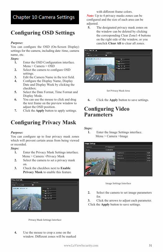
Configuring Privacy MaskPurpose:You can configure up to four privacymask zoneswhich will prevent certain areas from being viewed or recorded.Steps:
1. EnterthePrivacyMaskSettingsinterface.Menu > Camera >Privacy Mask
2. Select the camera to set a privacy mask on.
3. CheckthecheckboxnexttoEnable Privacy Mask to enable this feature.
Privacy Mask Settings Interface
4. Use the mouse to crop a zone on the window.Differentzoneswillbemarked
withdifferentframecolors.Note: Up to 4 privacy masks zones can be configuredandthesizeofeachareacanbeadjusted.5. Thedesignatedprivacymaskzoneson
the window can be deleted by clicking thecorrespondingClearZone1-4buttonsontherightsideofthewindow,oryoucanclick Clear All to clear all zones.
Set Privacy Mask Area
6. Click the Apply button to save settings.
Configuring Video Parameters
Steps:1. EntertheImageSettingsinterface.
Menu > Camera >Image
Image Settings Interface
2. Select the camera to set image parameters for.
3. Click the arrows to adjust each parameter.Click the Apply button to save settings.

www.LaViewSecurity.com32
Viewing Device InformationSteps:
1. EntertheSystemInformationinterface. Menu >Maintenance>System Info
2. Click the Device Info tab to see the Device Information menu where you can accessthedevicename,model,serialNo.,firmwareversionandencodingversion.
Device Information Menu
Viewing Camera InformationSteps:
1. EntertheSystemInformationinterface.Menu >Maintenance>System Info
2. Click the Camera tab to see the Camera Information menu where you can view the status of each camera.
Camera Information Menu
Viewing Record InformationSteps:
1. EntertheSystemInformationinterface.Menu >Maintenance>System Info
2. Click the Record tab to see the Record Information menu where you can access the recording status encoding parameters of each camera.
Record Information Menu
Viewing Alarm InformationSteps:
1. EntertheSystemInformationinterface.Menu >Maintenance>System Info
2. Click the Alarm tab to see the Alarm Information menu where you can access the alarm information.
Alarm Information Menu
Viewing Network InformationSteps:
1. EntertheSystemInformationinterface.Menu >Maintenance>System Info
2. Click the NetworktabtoseetheNetworkInformation menu where you can view the network information.
Network Information Menu
Viewing HDD InformationSteps:
1. EntertheSystemInformationinterface.Menu >Maintenance>System Info
2. Click the HDD tab to see the HDD

www.LaViewSecurity.com 33
Information menu where you can view the HDDstatus,freespace,property,etc.,
HDD Information Menu
Searching & Export Log FilesPurpose:Theoperation,alarm,exceptionandotherinformation about the DVR can be stored in log files,whichcanbeviewedandexportedatanytime.Steps:
1. EntertheLogSearchinterface.Menu >Maintenance>Log Search
Log Search Interface
2. Setthelogsearchconditionstorefineyoursearch:StartTime,EndTime,MajorTypeandMinorType.
3. Click the Searchbuttontofindmatchinglogfiles.
4. Thematchinglogfileswillbedisplayedon the list shown below.
Log Search Results
Note: Upto2000logfilescanbedisplayedatonce.
5. Youcanclickthe button of each log or double click it to view its detailed
information,youcanalsoclickthe buttontoviewtherelatedvideofilesifavailable.
Log Details
6. Ifyouwishtoexportthelogfiles,clickthe ExportbuttontoentertheExportmenu.

www.LaViewSecurity.com34
Export Log Files
7. Select the backup device from the dropdown list under Device Name.
8. Click Export toexportthelogfilestotheselected backup device.
Youcanclickthe New Folder button to createanewfolderinthebackupdevice,or click the Format button to format the backupdevicebeforelogexport.Notes:
1) Please connect the backup device to DVR beforeinitiatinglogexport.
2) Thelogfilesexportedtothebackupdevicearenamedaccordingtoexportingtime,e.g.,20110514124841logBack.txt.
To export all the log files:YoucanentertheLogExportinterface.Menu> Maintenance> Log Information> Log
Export
Log Export Interface
CheckthecheckboxnexttotheHDD,andclicktheExportbuttontoexportallthelogfilesstoredintheHDD.
Upgrading SystemPurpose:The firmware on your DVR can be upgraded bylocalbackupdeviceorremoteFTPserver.
Upgrading by Local Backup DeviceSteps:
1. Connect your DVR with a local backup devicewheretheupdatefirmwarefileislocated.
2. EntertheUpgradeinterface.Menu >Maintenance>Upgrade
3. Click the Local Upgrade tab to enter the local upgrade menu.
Local Upgrade Menu
4. Selecttheupdatefirmwarefilefromthebackup device.
5. Click the Upgrade button to start upgrade.
6. Aftertheupgradingiscomplete,reboottheDVRtoactivatethenewfirmware.
Restoring Default SettingsSteps:
1. EntertheDefaultinterface.Menu > Maintenance > Default
Restore Factory Default
2. Click the OK button to restore the default settings.
Note: Besides network parameters (IP address, subnet mask, gateway, MTU, default route and server port), all other parameters of the device will be restored to factory default settings.

www.LaViewSecurity.com 35
Configuring General SettingsPurpose:Configuretheoutputresolution,systemtime,andmousepointerspeed.Menu>Configuration>Generalinterface.Steps:
1. EntertheGeneralSettingsinterface.Menu>Configuration>General
2. Select the General tab.
General Settings Interface
3. Configurethefollowingsettings:• Language: Thedefaultlanguage
used is English.• Resolution: Select the output
resolution,whichmustbethesame as the resolution of the monitor screen.
• Time Zone: Select the time zone.• Date Format: Select the date
format.• System Date: Select the system
date.• System Time: Select the system
time.• Mouse Pointer Speed: Set the
speed of the pointer; 4 levels are configurable.
• Enable Wizard:Enable/disablethe Wizard to appear when the device starts up.
• Enable ID Authentication: Enable/disabletheuseofthelogin password.
4. Click the Apply button to save settings.
Configuring DST SettingsSteps:
1. EntertheGeneralSettingsinterface.Menu>Configuration>General
2. Select the DST Settings tab.
DST Settings Interface
CheckthecheckboxnexttotheAutoDSTAdjustmentitemorchecktheEnableDSTcheckbox,thenchoosethedateoftheDSTperiod.
Managing User AccountsPurpose:ThedefaultaccountintheDVRisAdministrator. The user name is admin and the password is 12345. TheAdministrator hasthepermissiontoadd/deleteusersandconfigureuserparameters.
Adding a UserSteps:
1. EntertheUserManagementinterface.Menu>Configuration>User
User Management Interface
2. Click the Add button to enter the Add User menu.
www.LaViewSecurity.com36
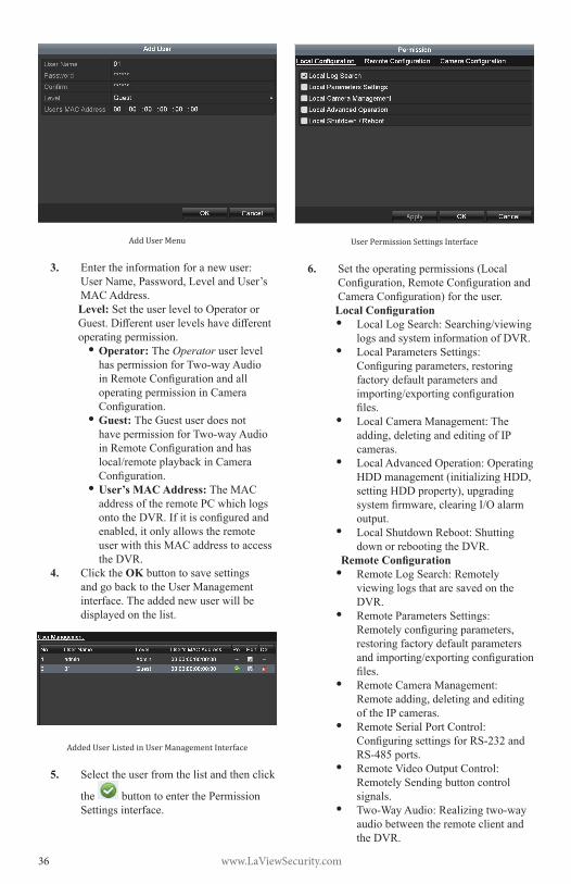
Add User Menu
3. Entertheinformationforanewuser: UserName,Password,LevelandUser’sMAC Address.Level: Set the user level to Operator or Guest.Differentuserlevelshavedifferentoperating permission.
• Operator: TheOperator user level haspermissionforTwo-wayAudioinRemoteConfigurationandalloperating permission in Camera Configuration.
• Guest: TheGuestuserdoesnothavepermissionforTwo-wayAudioinRemoteConfigurationandhaslocal/remoteplaybackinCameraConfiguration.
• User’s MAC Address: TheMACaddress of the remote PC which logs ontotheDVR.Ifitisconfiguredandenabled,itonlyallowstheremoteuser with this MAC address to access the DVR.
4. Click the OK button to save settings and go back to the User Management interface.Theaddednewuserwillbedisplayed on the list.
Added User Listed in User Management Interface
5. Select the user from the list and then click
the button to enter the Permission Settings interface.
User Permission Settings Interface
6. Set the operating permissions (Local Configuration,RemoteConfigurationandCameraConfiguration)fortheuser.Local Configuration • LocalLogSearch:Searching/viewing
logs and system information of DVR.• Local Parameters Settings:
Configuringparameters,restoringfactory default parameters and importing/exportingconfigurationfiles.
• LocalCameraManagement:Theadding,deletingandeditingofIPcameras.
• Local Advanced Operation: Operating HDDmanagement(initializingHDD,settingHDDproperty),upgradingsystemfirmware,clearingI/Oalarmoutput.
• Local Shutdown Reboot: Shutting down or rebooting the DVR.
Remote Configuration• Remote Log Search: Remotely
viewing logs that are saved on the DVR.
• Remote Parameters Settings: Remotelyconfiguringparameters,restoring factory default parameters andimporting/exportingconfigurationfiles.
• Remote Camera Management: Remoteadding,deletingandeditingof the IP cameras.
• Remote Serial Port Control: ConfiguringsettingsforRS-232andRS-485ports.
• Remote Video Output Control: Remotely Sending button control signals.
• Two-WayAudio:Realizingtwo-wayaudio between the remote client and the DVR.

www.LaViewSecurity.com 37
• Remote Alarm Control: Remotely arming(notifyalarmandexceptionmessagetotheremoteclient)andcontrolling the alarm output.
• Remote Advanced Operation: Remotely operating HDD (initializing HDD,settingHDDproperty),upgradingsystemfirmware,clearingI/Oalarmoutput.
• RemoteShutdown/Reboot:Remotelyshutting down or rebooting the DVR.
Camera Configuration• Remote Live View: Remotely
viewing live video from selected camera(s).
• Local Manual Operation: Locally starting/stoppingmanualrecording,photo capturing and alarm output of selectedcamera(s).
• Remote Manual Operation: Remotely starting/stoppingmanualrecording,photo capturing and alarm output of selectedcamera(s).
• Local Playback: Locally playing back recordedfilesfromselectedcamera(s).
• Remote Playback: Remotely playing backrecordedfilesfromselectedcamera(s).
• LocalPTZControl:LocallycontrollingPTZmovementofselectedcamera(s).
• RemotePTZControl:RemotelycontrollingPTZmovementofselectedcamera(s).
• LocalVideoExport:Locallyexportingrecordedfilesfromselectedcamera(s).
7. Click the OK button to save settings and exitinterface.
Note: Only the admin user account has the permission to restore factory default parameters.
Deleting a UserSteps:
1. EntertheUserManagementinterface.Menu>Configuration>User
2. Select the user to be deleted from the list.
User List
3. Click the icon to delete the selected user.
Editing a UserSteps:
1. EntertheUserManagementinterface.Menu>Configuration>User
2. Select the user to be edited from the list.
3. Click the icontoentertheEditUserinterface.Note: Theadminusercanalsobeedited.
Edit User Interface
4. Edituserinformation:Username,password,levelandMACaddress.CheckthecheckboxChange Password if you want to change the password of the current user.
5. Click the OK button to save settings and exitthemenu.

www.LaViewSecurity.com38
FAQ No image displayed on the monitor after
starting up normally.
Possible Reasons
a) NoVGAorHDMIconnections.
b) Connection cable is damaged.
c) Input mode of the monitor is incorrect.
Steps
1. Verify the device is connected to the monitorviaHDMIorVGAcable.
Ifnot,pleaseconnectthedevicewiththemonitor and reboot.
2. Verify the connection cable is good.
If there is still no image display on the monitorafterrebooting,pleasecheckiftheconnectioncableisgood,andchangeacableto connect again.
3. Verify Input mode of the monitor is correct.
Please check the input mode of the monitor matches with the output mode of the device (e.g. if the output mode of DVR is HDMI output,thentheinputmodeofmonitormustbetheHDMIinput).Andifnot,pleasemodify the input mode of monitor.
4. Check if the fault is solved by the step 1 to step 3.
Ifitissolved,finishtheprocess.
Ifnot,pleasecontacttheengineertodothefurther process.
There is an audible warning sound “Di-Di-Di-DiDi” after a new bought DVR starts up.Possible Reasons
a) NoHDDisinstalledinthedevice.
b) TheinstalledHDDhasnotbeeninitialized.
c) TheinstalledHDDisnotcompatiblewiththeDVRorisbroken-down.
Steps
1. Verify at least one HDD is installed in
the DVR.
1) Ifnot,pleaseinstallthecompatibleHDD.
Note: Pleaserefertothe“QuickOperationGuide”fortheHDDinstallation steps.
2) Ifyoudon’twanttoinstallaHDD,select“Menu>Configuration>Exceptions”,andunchecktheAudibleWarningcheckboxof“HDDError”.
2. Verify the HDD is initialized.
1) Select“Menu>HDD>General”.
2) If the status of the HDD is “Uninitialized”,pleasecheckthecheckboxofcorrespondingHDDandclickthe“Init”button.
3. Verify the HDD is detected or is in good condition.
1) Select“Menu>HDD>General”.
2) If the HDD is not detected or the statusis“Abnormal”,pleasereplacethe dedicated HDD according to the requirement.
4. Check if the fault is solved by the step 1 to step 3.
1) Ifitissolved,finishtheprocess.
2) Ifnot,pleasecontacttheengineertodothe further process.
The status of the added IPC displays as “Disconnected” when it is connected through Private Protocol. Select “Menu>Camera>Camera>IP Camera” to get the camera status.
Possible Reasons
a) Networkfailure,andtheDVRandIPClost connections.
b) Theconfiguredparametersareincorrectwhen adding the IPC.
c) Insufficientbandwidth.
Steps
1. Verify the network is connected.

www.LaViewSecurity.com 39
1) ConnecttheDVRandPCwiththeRS-232 cable.
2) OpentheSuperTerminalsoftware,andexecutethepingcommand.Input“pingIP”(e.g.ping172.6.22.131).
Note: Simultaneously press Ctrl and C toexitthepingcommand.
Ifthereexistsreturninformationandthetimevalueislittle,thenetworkisnormal.
2. Verifytheconfigurationparametersarecorrect.
1) Select“Menu>Camera>Camera>IPCamera”.
2) Verify the following parameters are the same with those of the connected IP devices,includingIPaddress,protocol,managementport,usernameandpassword.
3. Verify the whether the bandwidth is enough.
1) Select“Menu>Maintenance>NetDetect>NetworkStat.”.
2) Check the usage of the access bandwidth,andseeifthetotalbandwidth has reached its limit.
4. Check if the fault is solved by the step 1 to step 3.
Ifitissolved,finishtheprocess.
Ifnot,pleasecontacttheengineertodothefurther process.
The IPC frequently goes online and offline and the status of it displays as “Disconnected”.Possible Reasons
a) TheIPCandtheDVRversionsarenotcompatible.
b) Unstable power supply of IPC.
c) Unstable network between IPC and DVR.
d) Limitedflowbytheswitchconnectedwith IPC and DVR.
Steps
1. Verify the IPC and the DVR versions are compatible.
1) EntertheIPCManagementinterface“Menu>Camera>Camera>IPCamera”,andviewthefirmwareversionof connected IPC.
2) EntertheSystemInfointerface“Menu>Maintenance>SystemInfo>DeviceInfo”,andviewthefirmwareversionofDVR.
2. Verify power supply of IPC is stable.
1) Verify the power indicator is normal.
2) WhentheIPCisoffline,pleasetrytheping command on PC to check if the PC connects with the IPC.
3. Verify the network between IPC and DVR is stable.
1) WhentheIPCisoffline,connectPCandDVRwiththeRS-232cable.
2) OpentheSuperTerminal,usethepingcommand and keep sending large data packagestotheconnectedIPC,andcheckifthereexistspacketloss.
Note: Simultaneously press Ctrl and C toexitthepingcommand.
Example: Input ping 172.6.22.131 –l 1472 –f.
4. Verifytheswitchisnotflowcontrol.
Checkthebrand,modeloftheswitchconnectingIPCandDVR,andcontactwiththe manufacturer of the switch to check if it hasthefunctionofflowcontrol.Ifso,pleaseturn it down.
5. Check if the fault is solved by the step 1 to step 4.
Ifitissolved,finishtheprocess.
Ifnot,pleasecontacttheengineertodothefurther process.
No monitor connected with the DVR locally and when you manage the IPC to connect with the device by web browser remotely, of which the status displays as Connected.
www.LaViewSecurity.com40
And then you connect the device with the monitor via VGA or HDMI interface and reboot the device, there is black screen with the mouse cursor.
Connect the DVR with the monitor before startup via VGA or HDMI interface, and manage the IPC to connect with the device locally or remotely, the status of IPC displays as Connect. And then connect the device with the CVBS, and there is black screen either.
Possible Reasons:AfterconnectingtheIPCtotheDVR,theimageis output via the main spot interface by default.Steps:
1. Enabletheoutputchannel.
2. Select“Menu>Configuration>LiveView>View”,andselectvideooutputinterfaceinthedrop-downlistandconfigurethewindowyou want to view.
Notes:
1) TheviewsettingscanonlybeconfiguredbythelocaloperationofDVR.
2) Differentcameraordersandwindow-divisionmodescanbesetfordifferentoutputinterfacesseparately,anddigitslike“D1”and“D2”standsforthechannelnumber,and“X”meanstheselected window has no image output.
3. Check if the fault is solved by the above steps.
Ifitissolved,finishtheprocess.
Ifnot,pleasecontacttheengineertodothefurther process.
Live view stuck when video output locally.
Possible Reasons:
a) PoornetworkbetweenDVRandIPC,andthereexistspacketlossduringthetransmission.
b) Themotiondetectionandalarmfunctionsareenabled,andtheparametersofMainStream(Normal)andMainStream(Event)aredifferent.So the image looks stuck due to the imagechangesbetweendifferentresolutions.
c) Theframeratehasnotreachedthereal-time frame rate.
Steps:
1. Verify the network between DVR and IPC is connected.
1) Whenimageisstuck,connecttheRS-232 ports on PC and the rear panel of DVRwiththeRS-232cable.
2) OpentheSuperTerminal,andexecutethecommandof“ping 192.168.0.0 –l 1472 –f” (the IP address may change accordingtotherealcondition),andcheckifthereexistspacketloss.
Note: Simultaneously press Ctrl and C toexitthepingcommand.
2. Check the parameters of Main Stream (Normal)andMainStream(Event).
Select “Menu > Record > Parameters >Record”, and set the resolution of MainStream (Event) the sameas theoneofMainStream(Normal).
3. Verifytheframerateisreal-timeframerate.
Select “Menu > Record > Parameters >Record”,andsettheFrameratetoFullFrame.
4. Check if the fault is solved by the above steps.
Ifitissolved,finishtheprocess.If not, please contact the engineer to do thefurther process.
Live view stuck when video output remotely via the Internet Explorer or platform software.
Possible Reasons:
a) PoornetworkbetweenDVRandIPC,andthereexistspacketlossduringthetransmission.
b) PoornetworkbetweenDVRandPC,andthereexistspacketlossduringthetransmission.
c) Theperformancesofhardwarearenotgoodenough,includingCPU,memory,etc..
Steps:
1. Verify the network between DVR and IPC is connected.

www.LaViewSecurity.com 41
1) Whenimageisstuck,connecttheRS-232 ports on PC and the rear panel of DVRwiththeRS-232cable.
2) OpentheSuperTerminal,andexecutethecommandof“ping 192.168.0.0 –l 1472 –f” (the IP address may change accordingtotherealcondition),andcheckifthereexistspacketloss.
Note: Simultaneously press Ctrl and C toexit theping command.
2. Verify the network between DVR and PC is connected.
1) Open the cmd window in the Start menu,oryoucanpress“windows+R”shortcut key to open it.
2) Use the ping command to send large packettotheDVR,executethecommandof“ping192.168.0.0–l1472–f”(theIPaddressmaychangeaccordingtotherealcondition),andcheckifthereexistspacketloss.
Note: Simultaneously press Ctrl and C toexitthepingcommand.
3. Verify the hardware of the PC is good enough.
Simultaneously press Ctrl,Alt and Delete to enterthewindowstaskmanagementinterface,asshowninthefollowingfigure.
Windows task management interface Selectthe“Performance”tab;check
the status of the CPU and Memory. Iftheresourceisnotenough,please
end some unnecessary processes.
4. Check if the fault is solved by the above steps.
Ifitissolved,finishtheprocess.If not, please contact the engineer to do thefurther process.
When using the DVR to get the live view audio, there is no sound or there is too much noise, or the volume is too low.
Possible Reasons:
a) Cable between the pickup and IPC is not connected well; impedance mismatches or incompatible.
b) Thestreamtypeisnotsetas“Video&Audio”.
c) Theencodingstandardisnotsupportedwith DVR.
Steps:
1. Verify the cable between the pickup and IPC is connected well; impedance matches and compatible.
LogintheIPCdirectly,andturntheaudioon,check if the sound is normal. If not, pleasecontact the manufacturer of the IPC.
2. Verify the setting parameters are correct.
Select “Menu > Record > Parameters >Record”,andsettheStreamTypeas“Audio&Video”.
3. Verify the audio encoding standard of the IPC is supported by the DVR.
DVR supportsG722.1 andG711 standards,and if the encoding parameter of the input audioisnotoneoftheprevioustwostandards,youcanlogintheIPCtoconfigureittothesupported standard.
4. Check if the fault is solved by the above steps.
Ifitissolved,finishtheprocess.Ifnot,pleasecontact theengineer todo the
further process.
No record file found in the DVR local HDD, and prompt “No record file found”.
Possible Reasons:
a) Thetimesettingofsystemisincorrect.
www.LaViewSecurity.com42
b) Thesearchconditionisincorrect.
c) TheHDDiserrorornotdetected.
Steps:
1. Verify the system time setting is correct.
Select “Menu > Configuration > General >General”, and verify the “Device Time” iscorrect.
2. Verify the search condition is correct.
Select“Playback”,andverifythechanneland time are correct.
3. Verify the HDD status is normal.
Select“Menu>HDD>General”toviewtheHDDstatus,andverifytheHDDisdetectedand can be read and written normally.
4. Check if the fault is solved by the above steps.
Ifitissolved,finishtheprocess.
Ifnot,pleasecontacttheengineertodothefurther process.

www.LaViewSecurity.com 43