
1CH DIGITAL VIDEO RECORDER C-DR0100 ( NTSC SYSTEM ) C ...faq1.toaelectronics.com/media/C-DR0100...
56
Please follow the instructions in this manual to obtain the optimum results from this unit. We also recommend that you keep this manual handy for future reference. 1CH DIGITAL VIDEO RECORDER ( NTSC SYSTEM ) C-DR0100 C-DR0101 C-DR0105 INSTRUCTION MANUAL DIGITAL VIDEO RECORDER DISK FULL/ FAILURE ALARM RESET BUZZER STOP SEARCH MENU SELECT BLOCK PLAY STOP PLAY PAUSE REVERSE PLAY REC TIMER FRAME FRAME OUTPUT VIDEO AUDIO
Transcript of 1CH DIGITAL VIDEO RECORDER C-DR0100 ( NTSC SYSTEM ) C ...faq1.toaelectronics.com/media/C-DR0100...
Please follow the instructions in this manual to obtain the optimum results from this unit. We alsorecommend that you keep this manual handy for future reference.
1CH DIGITAL VIDEO RECORDER( NTSC SYSTEM )
C-DR0100C-DR0101C-DR0105
INSTRUCTION MANUAL
DIGITAL VIDEO RECORDER
DISK FULL/
FAILUREALARMRESET
BUZZER STOP
SEARCH
MENU
SELECTBLOCK
PLAYSTOP
PLAY
PAUSE
REVERSEPLAY
REC
TIMER
FRAME
FRAME
OUTPUT
VIDEO AUDIO

2
TABLE OF CONTENTS
1. SAFETY PRECAUTIONS ............................................................................... 5
2. GENERAL DESCRIPTION ............................................................................. 6
3. FEATURES .......................................................................................................... 6
4. HANDLING PRECAUTIONS .......................................................................... 7
5. NOMENCLATURE AND FUNCTIONS Front Panel ................................................................................................................ 8Rear Panel .............................................................................................................. 10
6. SETTING ITEM CHART AND SETTING PROCEDURES6.1. Basic Setting Procedures ................................................................................. 116.2. Setting Item Chart ............................................................................................ 12
7. INDIVIDUAL ITEM SETTINGS7.1. Main Menu Screen ........................................................................................... 137.2. Playback Settings ............................................................................................ 137.3. Clock Settings .................................................................................................. 14
7.3.1. Summer Time (Daylight Saving Time) Settings ..................................... 157.4. Disk Settings .................................................................................................... 157.5. Recording Settings ........................................................................................... 16
7.5.1. General Recording Settings ................................................................... 177.5.2. Internal Timer Recording Settings ......................................................... 177.5.3. Alarm Recording Settings ...................................................................... 197.5.4. About the Alarm Input Mode .................................................................. 20
7.6. Screen Display Settings ................................................................................... 217.7. Key Lock .......................................................................................................... 22
7.7.1. Key Lock Release .................................................................................. 227.8. Communication Settings .................................................................................. 23
7.8.1. Network Settings .................................................................................... 237.9. Log Display ...................................................................................................... 24
7.9.1. General/Timer Recording Logs .............................................................. 247.9.2. Alarm Recording Logs ........................................................................... 247.9.3. Failure Logs ........................................................................................... 25
7.10. System Maintenance ..................................................................................... 257.10.1. Menu Default Settings .......................................................................... 257.10.2. Disk Formatting .................................................................................... 26
SETTING BASICS
SUMMARY
3
8. DIGITAL VIDEO RECORDER ACTIVATION AND TERMINATION8.1. Recorder’s Activation ....................................................................................... 278.2. When the Failure Screen Is Displayed ............................................................. 288.3. Recorder’s Termination .................................................................................... 28
9. OPERATION AFTER POWER FAILURE RESTORATION9.1. When the Power Fails during Recording ......................................................... 28
10. RECORDING10.1. Type of Recording .......................................................................................... 29
10.1.1. Recording Priorities ............................................................................ 2910.2. Screen Display During Recording .................................................................. 2910.3. The Keys to Be Used in Recording ................................................................ 3110.4. Performing General Recording ...................................................................... 3110.5. Performing Internal Timer Recording ............................................................. 3110.6. Performing Alarm Recording .......................................................................... 32
11. PLAYBACK11.1. Type of Playback ........................................................................................... 3311.2. Screen Display During Playback .................................................................... 3311.3. The Keys to Be Used in Playback .................................................................. 3411.4. Performing Playback ...................................................................................... 3411.5. Performing Various Playback Functions
11.5.1. Reverse Playback .............................................................................. 3411.5.2. Fast Forward Playback And Fast Reverse Playback ......................... 3411.5.3. Playback Pause (Still Picture) ............................................................ 3411.5.4. Forward Frame Playback And Reverse Frame Playback .................. 3511.5.5. Forward Block Playback And Reverse Block Playback ..................... 35
11.6. About the Playback Start Position .................................................................. 36
12. SEARCH FUNCTIONS12.1. The Keys to Be Used in Searching ................................................................ 3712.2. Date/Time and Block Searches ..................................................................... 37
12.2.1. Basic Date/Time and Block Search Operations ................................. 3712.2.2. Date/Time Search Operation ............................................................. 3712.2.3. Block Search Operation ..................................................................... 38
12.3. Time Shift Search .......................................................................................... 39
13. CONNECTIONS13.1. Preparations for Connections ........................................................................ 40
13.1.1. Control Input/Output Terminal Connections ....................................... 4013.2. When Using the 24 V AC or 12 V DC or AC Mains Camera .......................... 4013.3. Connection to The Monitor TV ....................................................................... 4013.4. Combination With The Digital Video Recorder/Multi-switchers
(C-MS91D, C-MS161D) ................................................................................. 4113.4.1. Basic System ..................................................................................... 4113.4.2. Expansion System (Series Recording) .............................................. 41
CONNECTIONS
FUNCTIONS
OPERATION

4
14. CONNECTION EXAMPLES14.1. Connection to the 24 V AC or 12 V DC or AC Mains Camera ....................... 4214.2. Connection to the Multi-switcher
14.2.1. Basic System (Combined Example with the C-MS91D, Multi-switcher) ................... 43
14.2.2. Expansion System (Combined Example with the C-MS91D, Multi-switcher) ................... 44
15. RECORDING TIME TABLE15.1. Recording Picture Quality Setting .................................................................. 4515.2. When using the C-DR0100 ............................................................................ 4515.3. When using the C-DR0101 ............................................................................ 4515.4. When using the C-DR0105 ............................................................................ 46
16. EXTERNAL TERMINAL SPECIFICATIONS16.1. RS-232C Communication Specifications ....................................................... 47
16.1.1. The Rules of Overall Communications .............................................. 4716.1.2. Communication Protocol .................................................................... 4716.1.3. RS-232C Connector Pin Assignment ................................................. 4716.1.4. RS-232C Communication Format
(Controller to Digital Video Recorder) ................................................ 4816.1.5. RS-232C Communication Command
(Controller to Digital Video Recorder) ................................................ 4816.1.6. RS-232C Communication Format
(Digital Video Recorder to Controller) ................................................ 5116.1.7. RS-232C Communication Command
(Digital Video Recorder to Controller) ................................................ 5116.2. About the Ethernet Terminal .......................................................................... 53
17. RACK MOUNTING ........................................................................................... 54
18. IF YOU THINK THERE IS A FAILURE: (TROUBLESHOOTING) .... 55
19. SPECIFICATIONS ........................................................................................... 56
WHEN YOU NEED HELP
ADDITIONAL INFORMATION
NoteThis equipment has been tested and found to comply with the limits for a Class A digital device,pursuant to Part 15 of the FCC Rules. These limits are designed to provide reasonable protectionagainst harmful interference when the equipment is operated in a commercial environment. Thisequipment generates, uses, and can radiate radio frequency energy and, if not installed and used inaccordance with the instruction manual, may cause harmful interference to radio communications.Operation of this equipment in a residential area is likely to cause harmful interference in which case theuser will be required to correct the interference at his own expense.
ModificationsAny modifications made to this device that are not approved by TOA Corporation may void the authoritygranted to the user by the FCC to operate this equipment.
NTSC version complies with Part 15 of the FCC Rules.

5
1. SAFETY PRECAUTIONS
• Be sure to read this safety instructions in this section carefully in prior to use. • Make sure to observe the instructions in this manual as the conventions of safety symbols and messages
regarded as very important precautions are included.• Keep this instructions handy for future reference.
Safety Symbol and Message Conventions Safety messages described below are used to prevent bodily injury and property damage that could resultfrom mishandling. Before operating your product, read this manual first and understand messages so you arethoroughly aware of the potential safety hazards.
When installing the Recorder
• This is a class A product. In a domestic environment this product may cause radio interference in which casethe user may be required to take adequate measures.
• Do not expose the unit to rain or an environment where it may be splashed by water or other liquids, asdoing so may result in fire or electric shock.
• Use the unit only with the voltage specified on the unit. Using a voltage higher than specified one may resultin fire or electric shock.
• Do not damage, modify nor put the power supply cord in close to heaters. Never place heavy objects on thepower supply cord, as doing so may result in fire or electric shock.
• Do not install nor place the unit in unstable locations, such as on a rickety table or a slanted surface. Doingso may result in the unit falling down or dropping and causing personal injury.
When Using the Recorder
• Should the following irregularity be found during use, immediately switch off the main power, disconnect thepower supply plug from the AC outlet and contact your nearest TOA dealer. Make no further attempt tooperate the unit in this condition as this may cause fire or electric shock.
• If you detect smoke or a strange smell coming form the unit• If water or any metallic object gets into the unit• If the unit falls or the unit case breaks• If the power supply cord is damaged (exposure of the core, disconnection, etc.)• When the Screen is not Displayed
• Do not open the unit case nor modify the unit. As doing so may result in fire or electric shock as there arehigh voltage components inside the unit. Refer any needed servicing to authorized TOA dealers.
• Do not put containers of liquid or metallic objects on top of the unit. If they accidentally spill into the unit, thismay cause a fire or electric shock.
• Do not insert nor drop metallic objects or flammable materials from ventilation slots of the unit, as this mayresult in fire or electric shock.
• Do not touch power supply plug during thunder and lightning, as this may result in electric shock.
Indicates a potentially hazardous situation which could result in death orserious personal injury if ignored or mishandled.WARNING
Indicates a potentially hazardous situation which could result inmoderate or minor personal injury, and/or property damage if ignoredor mishandled.
CAUTIONWhen installing the Recorder
• Do not plug in nor remove the power supply plug with wet hands, as doing so may cause electric shock.• When unplugging the power supply cord, be sure to grasp the power supply plug; never pull the cord itself,
as doing so may result in damage the cord, causing fire or electric shock.• Moving the unit with the power supply cord connected to the wall outlet may cause damage to the power
supply cord, resulting in fire or electric shock.• Do not block the ventilation slots as this may cause inside of the unit filled with heat, as doing so may result
in fire.• Do not install the unit in humid or dusty locations, in locations exposed to the direct sunlight, near the
heaters, nor in locations generating soot or steam as doing so may result in fire or electric shock.

3. FEATURES
High Picture QualityDigital compression system ensures high-quality picture, audio recording, and playback.
Extended-Time RecordingBuilt-in 120 GB (C-DR0100), 240 GB (C-DR0101) and 500 GB (C-DR0105) large-capacity hard disks permitextended-time recording.
Can Be Used In Conjunction With SwitchersCan be connected to TOA’s switcher system and used in place of analog time-lapse VCRs. In systems thatuse a Multi-switcher (C-MS91D and C-MS161D), the Series Recording function that permits continuousrecording with the connection of two Digital Video Recorders can be enabled, and the switcher’s motiondetection function can be used as an alarm input to provide efficient surveillance by means of AlarmRecording.
Simultaneous Recording/Playback Recorded images can be played back without interrupting recording.
Pre-Alarm Recording Pre-Alarm function performs retroactive recording to a maximum of 5 minutes before alarm activation.
Search FunctionThree search functions Date/Time Search, Block Search, and Time Shift Search permit desired scenes to bequickly found and viewed.
Mirroring Recording (C-DR0101, C-DR0105)The C-DR0101 and C-DR0105 has two built-in hard disk drives. Mirroring refers to the simultaneous recordingof data onto the two hard disks. Even if one of the disks fails, recording and playback can still be performedusing the other disk. The possibility of data loss due to hard disk failure is greatly reduced, increasingreliability.
Networking FunctionAn RS-232C interface and a 100BASE-TX Ethernet port are standard.
Note: The RS-232C control software is not standard.6
Indicates a potentially hazardous situation which could result inmoderate or minor personal injury, and/or property damage if ignoredor mishandled.
CAUTIONWhen Using the Recorder
• Do not place heavy objects on the unit. Such object may fall or the unit may tip over, possibly resulting inpersonal injury.
• Clean the unit periodically. Contact your TOA dealer regarding the cleaning. If dust is allowed to accumulatein the unit over a long period of time, a fire may result.
• Clean the power supply plug and wall AC outlet periodically. If dust accumulates on them, a fire may result.Insert the power supply plug into the AC outlet securely.
• Switch off the main power and unplug the power supply plug from the AC outlet for the safety purposeswhen cleaning or leaving the unit unused for long periods of time. Doing otherwise could cause fire orelectric shock.
2. GENERAL DESCRIPTION
The TOA C-DR0100 (C-DR0101, C-DR0105) is a single-channel Digital Video Recorder with 1 channel ofvideo input, and permits connected camera images to be recorded onto its large-capacity internal hard disksusing a digital compression system. It can simultaneously play back recorded camera images while continuingto record images onto the hard disk. The Digital Video Recorder can also be easily connected to an existingswitcher system, replacing previously installed analog time-lapse VCRs. Mounting in EIA-Standard equipmentracks can also be easily performed with the addition of optional rack mounting brackets.

7
4. HANDLING PRECAUTIONS
• Use the Digital Video Recorder in locations with ambient temperature of between +5°C and +40°C, andhumidity levels of less than 80% to ensure that no condensation is formed.
• When moving the Recorder, first switch off the main power and then wait at least 30 seconds before moving. • Avoid moving the Recorder suddenly from a cold location to a warm location, or installing it in close proximity
to an air-conditioner outlet, as internal condensation could result. When condensation occurs, do not switchon the power until the Recorder has sufficiently dried.
• Avoid installing the Recorder in humid or dusty locations, or in locations exposed to direct sunlight, sootysmoke or steam. Note that even in locations which are not particularly dusty, dust may accumulate at theRecorder’s ventilation slots. Because this could cause an extreme rise in temperature inside the Recorder,be sure to clean the ventilation slots periodically after switching off the main power and disconnecting thepower supply cord from the AC outlet. It is highly recommended that the ventilation slots be cleaned once ayear.
• The socket-outlet shall be installed near the equipment and the plug (disconnecting device) shall be easilyaccessible.
• To clean, be sure to first switch off the main power and then wipe with a dry cloth. If the Recorder isparticularly dirty, use a cloth damped in a neutral detergent. Never use benzene, thinner or chemically-impregnated towels, which may damage the Recorder’s surface.
• Do not block the ventilation slots or cooling fan, which could cause the temperature inside the Recorder torise, possibly resulting in unit failure. Install the Recorder at least 100 mm away from the nearest wallsurface.
• Since the Recorder is equipped with a cooling fan, a motor sound is generated. • Do not install the Recorder in locations influenced by strong electrical or magnetic fields, as monitor screen
pictures may become distorted or the Recorder could fail. • Avoid jarring or striking the Recorder. The Recorder is a piece of precision equipment and accidentally
dropping it or subjecting it to strong impacts could cause its failure. When transporting the Recorder,carefully pack it in the supplied carton to protect it from shock.
• Do not use the Recorder in locations exposed to vibration to avoid failure. Avoid installing the Recordervertically or tilting it at extreme angles, since it is designed to be used in a horizontal position only.
• About the hard disksHard disks other than those specified by TOA cannot be used. Since the hard disks are pieces of precisionequipment, take special care in handling not to accidentally drop, bump or jar them, lest they should fail. If a hard disk on which condensation is formed is used, it could fail. Therefore, when brought into a warmroom from the cold outdoors, be sure to leave it unused for at least half a day before using it. If the hard diskfails, recorded data cannot be restored.
• TOA takes no responsibility for any incidental damage, such as loss of sales opportunities, that may resultfrom the Digital Video Recorder’s failure.
• The standby function is used to enable transportation of the unit from one place to another whencircumstances do not permit its main power supply to be turned off. While in standby mode, power continuesto be supplied to the unit, but its hard disk and fan are stopped. If the unit is left in standby mode for longperiods of time, heat can build-up inside the unit, potentially shortening its operating life. To avoid this, besure to turn off the main power supply when the unit is not in use.
Underwriters Laboratories Inc. (UL) has not tested the performance or reliability of the security aspectsof this product. UL has only tested for fire, shock or casualties as outlined in UL's Standard(s) forSafety. UL Certification does not cover the performance or reliability of the security hardware andsecurity operating software. UL MAKES NO REPRESENTATIONS, WARRANTIES ORCERTIFICATIONS WHATSOEVER REGARDING THE PERFORMANCE OR RELIABILITY OF ANYSECURITY RELATED FUNCTIONS OF THIS PRODUCT.

8
DIGITAL VIDEO RECORDER
DISK FULL/ FAILURE
ALARMRESET
BUZZER STOP
SEARCHMENUSELECT
BLOCK
PLAYSTOPPLAYPAUSE
REVERSEPLAYRECTIMER
FRAME FRAME
OUTPUT
VIDEO AUDIO
12 3 4 5 6 7 8 9 10 1112 13 1415 16
5. NOMENCLATURE AND FUNCTIONS
[Front Panel]
Standby Key [ ]Pressing this switch while the main power issupplied initiates a system check (the switchflashes green) and activates the Digital VideoRecorder (the switch lights green). Holding downthis switch for 1 second or more places theRecorder in standby mode, indicated by theswitch flashing every 5 seconds. NoteSome time is required before the Recorder isplaced in standby mode after the main power hasbeen switched on. Ensure that the Recorder is instandby mode before operating the standby key.
Timer KeyThis key lights green when pressed, indicatingthat the Recorder is in Internal Timer Recordingstandby mode, which permits Internal TimerRecording to be performed at preset times. Tocancel Internal Timer Recording, hold down theTimer key for at least 1 second until its lightextinguishes.
Recording [ / ] Key This key lights red when pressed, indicating thatcamera recording is in progress. To stop therecording, hold down the Recording key for atleast 1 second until its light extinguishes.
Reverse Playback [ ] KeyPlays back recorded images in the reversedirection. This key continuously lights greenduring reverse playback. The playback speedcycles through x1, x2, x4, and x8 with eachdepression of this key.
Frame Reverse [ ] Key Pressing this key while the Recorder is inPlayback Pause mode initiates a frame-by-framereverse playback of the recorded image. Holdingdown this key performs a continuous frame-by-frame playback in the reverse direction.
Pause [ ] KeyTemporary stops playback. This key continuouslylights green while in Playback Pause mode. Ifpressed again, images are played back in thesame direction as before. (Playback speedreverts to normal x1 speed.) When the Pause keyflashes green, this indicates that the Recorder isin Time Shift Search mode.
Playback [ ] KeyPlays back recorded images in the forwarddirection, and continuously lights green duringplayback. The playback speed cycles through x1,x2, x4, and x8 with each depression of thePlayback key.
Frame Advance [ ] KeyPressing this key while the Recorder is inPlayback Pause mode initiates a frame-by-frameplayback of the recorded image. Holding downthis key performs a continuous frame-by-frameplayback in the forward direction.
Playback Stop [ ] KeyStops playback operation. NoteCurrent recording in progress does not stop evenif this key is pressed.
[ + ] and [ – ] Set Keys Used to change setting values on the menu orsearch screen.
Block Shift Key Pressing the (+) key during playback shifts therecorded image block to the next block in theforward direction, while the (–) key shifts to thepreceding block.
Up [ ] and Down [ ] Shift KeysUsed to move the cursor on the menu or searchscreen.
Select KeySelects items or choices on the menu or searchscreen.
Menu KeyHold down this key for 1 second or more todisplay the main menu screen on the monitor.Pressing this key during playback stops playbackoperation to display the main menu screen. Themain menu screen can also be displayed evenwhile recording is in progress, however someitems cannot be set during recording. If this key ispressed during item selection, the displayedsetting contents are set and confirmed, returningthe display to the previous screen.
11
10
9
8
7
6
5
4
3
2
1

9
Search KeyDisplays the search screen on the monitor.Pressing this key during playback stops playbackoperation to display the search screen. If pressedwhile in Playback Pause mode, the Time ShiftSearch screen is displayed. To exit the searchscreen, press this key again.
Buzzer Stop KeyThis key flashes red when an alarm is activated,and the Recorder’s built-in buzzer is sounded toprovide both visual and audio alarm warnings.After Alarm Recording completion, the keychanges to steady ON (red). Press this key tostop the buzzer. The buzzer can be disabled byselecting "OFF" for Buzzer in the AlarmRecording Settings. (Refer to p. 19.)
Alarm Reset KeyHold down this key for 1 second or more to resetalarm operation and stop Alarm Recoding.
Disk Full/Failure IndicatorDisk Full IndicatorWhen the Recording mode is set to "STOP" or"SERIES" in the Disk Setting, the indicatorflashes whenever less than 1 hour of availablehard disk time remains, and changes to steadyON if no available time remains.
Failure IndicatorThis indicator lights red when the Recorder fails,and extinguishes when the cause of the failure isremoved. This failure indication takes precedenceover the Disk Full indication, should both beenabled at the same time. Possible FailureCauses: Hard disk failure, fan failure, and videoloss. NoteIf the Recorder should indicate a failure, firstcheck for the cause by switching the power OFF,then contact your TOA dealer if unable to solvethe problem.
Video Output TerminalUsed for dubbing recorded video images. Thisterminal is the same as the Video OutputTerminal located on the rear panel.
Audio Output TerminalUsed for dubbing recorded audio signals. Thisterminal is the same as the Audio OutputTerminal located on the rear panel.
16
15
14
13
12

10
AC MAINS MAIN POWER
ON
OFF
IN OUT IN OUT
VIDEO SW VIDEO IN
OUT
AUDIO GND GND100BASE–TX
ALARM RESET OUTALARM INSW CTRL OUT
TIME SYNC INREC STOP IN
REC START INALARM RESET IN
TIME SYNC OUTALARM OUT
FAILURE OUTDISK FULL OUT
RS–232C
21 22 23 24 25 26 27 2818 1917 20
AC InletConnect the supplied power cord to this socket.
Main Power SwitchPower switch for the Digital Video Recorder.
Video Input TerminalReceives video signals. Connect the Multi-switcher’s VCR output to this terminal whenconnecting the Multi-switcher.
Video Output TerminalSends out video signals. Connect this terminal tothe Multi-switcher’s VCR input when connectingthe Multi-switcher. If the Multi-switcher is notused, connect this terminal to the monitor totransmit video signals to the monitor.
Switcher Video Input TerminalConnect the Multi-Switcher’s monitor output tothis terminal. This terminal is not used if the Multi-switcher is not connected.
Switcher Video Output TerminalIn the system in which the Multi-switcher isconnected, connect this terminal to the monitor totransmit video signals to the monitor. Do not usethis terminal if the Multi-switcher is not connected.
Audio Input TerminalReceives audio signals from the drive unit, etc.
Audio Output TerminalSends out audio signals to the monitor, etc.
Control Input/Output TerminalAlarm Reset Output TerminalShorts to the ground terminal when theRecorder’s alarm is reset.
Alarm Input TerminalActivates an alarm by way of external sensors.Alarm Input mode can be changed by theRecording Setting’s Alarm Recording Setting.
Ground Terminal
Switcher Control Output TerminalConnect this terminal to the Multi-switcher’sswitcher control input terminal.
100BASE-TX Terminal RJ-45 terminal for Ethernet.
Control Input/Output TerminalAlarm Reset Input TerminalUsed to permit external equipment to reset theRecorder’s alarm operation. This terminalprovides the same operation as the front panel-mounted Alarm Reset key.
Recording Start Input TerminalUsed to permit external equipment to initiaterecording. When the Disk Setting’s Disk Mode isset to "SERIES," even if the Recorder’s disk isfull, the Disk Full status is reset and recording isstarted.
Recording Stop Input TerminalUsed to stop recording at external equipment.This terminal provides the same operation as thefront panel-mounted Recording key.
Time Sync Input/Output Terminals Synchronize multiple Digital Video Recorders withthat of a specified recorder (master unit) whentwo or more recorders are used. Connect themaster unit’s output to the slave unit’s input.
Alarm Output TerminalShorts to the ground terminal when an alarm isactivated.
System Failure Output TerminalShorts to the ground terminal when the hard diskor fan failure or Video Loss occurs.
Disk Full Output TerminalShorts to the ground terminal when no availablehard disk time remains.
RS-232C TerminalConnect this terminal to a computer’s RS-232Cterminal when controlling the Recorder at thecomputer. Connect this terminal to the Multi-switcher’s RS-232C terminal to synchronize theRecorder with the Multi-switcher. (This terminalcan be connected to any of the C-MS91D, C-MS161D Multi-switchers.)
*Ratings and serial numbers are indicated on thebottom surface.
28
27
26
25
24
23
22
21
20
19
18
17
[Rear Panel]

ALARM REC SETTING
ALARM SETTING [ VALID]ALARM IN MODE [ EDGE]PRE–ALARM [20SEC]ALARM PERIOD [10SEC]POST–ALARM [10SEC]PICTURE [LEVEL3]AUDIO [ ON]REC INTERVAL [1/30SEC]BUZZER [ ON]ALARM OUT [DURING REC]
11
MAIN MENU
• PLAY SETTINGCLOCK SETTINGDISK SETTINGREC SETTINGON–SCREEN DISP SETTINGKEY LOCKCOMMUNICATION SETTING LOG DISPLAYSYSTEM MAINTENANCE
MAIN MENU
PLAY SETTINGCLOCK SETTINGDISK SETTING
• REC SETTING ON–SCREEN DISP SETTINGKEY LOCKCOMMUNICATION SETTINGLOG DISPLAY SYSTEM MAINTENANCE
REC SETTING
• GENERAL REC SETTINGTIMER REC SETTINGALARM REC SETTING
REC SETTING
GENERAL REC SETTINGTIMER REC SETTING
• ALARM REC SETTING
REC SETTING
• GENERAL REC SETTINGTIMER REC SETTINGALARM REC SETTING
MAIN MENU
• PLAY SETTINGCLOCK SETTINGDISK SETTINGREC SETTINGON–SCREEN DISP SETTINGKEY LOCKCOMMUNICATION SETTINGLOG DISPLAYSYSTEM MAINTENANCE
2. Enter the setting screen.
3. Select the setting value.
4. Confirm the selected setting value and return to the camera display screen.
Camera Display Screen Main Menu Screen
Setting screen
Camera Display Screen
ALARM REC SETTING
ALARM SETTING [ VALID]ALARM IN MODE [ EDGE]PRE–ALARM [20SEC]ALARM PERIOD [10SEC]POST–ALARM [10SEC]PICTURE [LEVEL1]AUDIO [ ON]REC INTERVAL [1 /30SEC]BUZZER [ ON]ALARM OUT [DURING REC]
Press key for 1second or more
MENUkey
+ key
keySELECT
key
THU JAN/01/0400:00:00
THU JAN/ 01/ 0400:00:00
orkey
or
- key
ALARM REC SETTING
ALARM SETTING [ VALID]ALARM IN MODE [ EDGE]PRE–ALARM [20SEC]ALARM PERIOD [10SEC]POST–ALARM [10SEC]PICTURE [LEVEL3]AUDIO [ ON]REC INTERVAL [1 /30SEC]BUZZER [ ON]ALARM OUT [DURING REC]
6. SETTING ITEM CHART AND SETTING PROCEDURES
6.1. Basic Setting Procedures
• The shaded item in the figure refers to the cursor position.
1. Enter the main menu screen.
SELECTkey
key
orkey
key
orkey
MENUkey
MENUkey
MENUkey

12
Main Menu Playback Settings (p. 13)
Clock Settings (p. 14)
Disk Settings (p. 15)
Recording Settings (p. 16)
Screen Display Settings (p. 21)
Key Lock (p. 22)
Communication Settings (p. 23)
Log Display (p. 24)
Playback Mode
Simultaneous Recording/Playback
Year/Month/Day
Main Menu Item Menu Item Setting Item
Disk Mode
Recording Mode
Picture Quality
Audio
Recording Intervals
Switcher Control Period
Recoding Start Date
Preset Time
Picture Quality
Audio
Recording Intervals
Recording Pattern
Motion Detection Pattern
Alarm Settings
Alarm Input Mode
Pre-Alarm Recording Periods
Alarm Recording Periods
Post-Alarm Recording Periods
Picture Quality
Audio
Recording Intervals
Buzzer Sound
Alarm Output Time
Picture Quality Indication
Audio ON/OFF Indication
Recording Mode Indication
Recording Indication
Playback Indication
Remaining Time Indication
Date Indication
Time Indication
Date/Time Display Position
Disk Mode Indication
RS232C Baud Rate
RS232C Flow Control
Network Settings
Switcher Synchronization
Disk Selection
IP Address
Subnet Mask
Default Gateway
General Recording Settings (p. 17)
Internal Timer Recording Settings (p. 17)
General/Timer Recording Log
Alarm Recording Log
Failure Log
Menu Default Settings
Disk Formatting
Timer Setting List
Timer Setting 01–10
Time Synchronization
Synchronization Time
Alarm Recording Settings (p. 19)
System Maintenance (p. 25)
*
*
*
Summer Time
6.2. Setting Item Chart
* This setting item is applicable to the C-DR0101 and C-DR0105 Recorder, and not displayed on the screenwhen the C-DR0100 Recorder is used.

13
Setting Value ContentsSetting Item
7.2. Playback Settings
Playback mode settings are only available to the C-DR0101 and C-DR0105, and not displayed when the C-DR0100 is used.
PLAY MODE : Sets the hard disk to be used for playback and search functions.SIMUL REC/PLAY : Selects "ALLOW" or "DISALLOW" for simultaneous recording and playback operations.
• Move the cursor with the ( ) or ( ) key, and change setting valueswith the (–) or (+) key.
• Confirm the setting with the Menu key, and return to the previousscreen.
• Each setting item and its setting value and contents are as shown inthe table below.
PLAY MODE
(Playback Mode)
(C-DR0101, DR0105)
SIMUL REC/PLAY
(Playback during
Recording)
ALL : All set hard disks are used for playback.
HDD-A : Hard disk drive A is used for playback.
HDD-B : Hard disk drive B is used for playback.
ALLOW : Allows playback while recording.
DISALLOW : Disallows playback while recording.
ALL / HDD-A / HDD-B
ALLOW / DISALLOW
PLAY SETTING
PLAY MODE [ ALL]SIMUL REC/ PLAY
[ ALLOW]
* The underlined contents are factory-preset values.
• Select the desired item from 9 main menu items on themain menu screen.
• Move the cursor with the ( ) or ( ) key, and display eachsetting screen with the Select key.
MAIN MENU
• PLAY SETTINGCLOCK SETTINGDISK SETTINGREC SETTINGON–SCREEN DISP SETTINGKEY LOCKCOMMUNICATION SETTINGLOG DISPLAYSYSTEM MAINTENANCE
Refer to P.13Refer to P.14Refer to P.15Refer to P.16Refer to P.21Refer to P.22Refer to P.23Refer to P.24Refer to P.25
NoteBe sure to first perform Clock Settings (Refer to p. 14) before performing each setting.
7. INDIVIDUAL ITEM SETTINGS
7.1. Main Menu Screen
Hold down the Menu key for 1 second or more on the screen displaying the camera to display the MainMenu screen.

CLOCK SETTING
THU JAN / 01 / 04 00:00:00TIME SETTING : SELECT KEY
TIME SYNC [ SLAVE]SYNC TIME [00H]SUMMER TIME SETTING
<CURRENT TIME>THU JAN / 01 / 04 00:00:00
14
7.3. Clock Settings
Set the date and time. Perform this setting when the Recorder is used for the first time or when the date andtime indication has been deleted because the power was switched off for a long period of time.
Note• Previously logged data times are not updated even if the Clock Settings are changed during use. • The data times will be lost if the power was switched off for 30 days or more. Set the date and time again.
Memory backup: 720 hours (fully charged)
TIME SYNC : Synchronizes the times of other Recorders (slave units) with that of a specified Recorder(master unit) when multiple Recorders are used.
SYNC TIME : Sets the synchronization time.
NoteThe Time Sync function cannot be operated during recording.
• Move the cursor with the ( ) or ( ) key, and change setting valueswith the (–) or (+) key.
• After completing the settings of time (hour, minute, second), confirmthe time with the Select key.
• The indication "Clock Setting Completed" is displayed on the screenafter setting completion.
• Current time is displayed in the lowest part of the screen. • Confirm the setting with the Menu key, and return to the previous
screen. • Each setting item and its setting value and contents are as shown in
the table below.
Setting Value ContentsSetting Item
TIME SYNC
(Time
Synchronization)
SYNC TIME (Synch-
ronization Time)
MASTER: Designates the master unit.
SLAVE: Designates the slave unit.
Select and set the synchronization time.
MASTER / SLAVE
00H / 01H / 02H / 03H / 04H / ...
up to 23H
* The underlined contents are factory-preset values.
NoteSetting the Time Sync settings to "SLAVE," and the Disk Setting’s Disk Mode to "SERIES" places theRecorder in Disk Full mode, causing the Disk Full indicator to light. Perform this setting when using SeriesRecording. Refer to p. 41; Expansion System (Series Recording).

15
Setting Value ContentsSetting Item
7.4. Disk Settings
Disk Mode Settings are only available to the C-DR0101, and not displayed when the C-DR0100 is used.
DISK MODE : Sets the hard disk recording method.REC MODE : Selects "RE-REC","STOP," or "SERIES" for hard disks.
• Move the cursor with the ( ) or ( ) key, and change setting valueswith the (–) or (+) key.
• Confirm the setting with the Menu key, and return to the previousscreen.
• Each setting item and its setting value and contents are as shown inthe table below.
DISK MODE
(C-DR0101, C-DR0105)
NORMAL : Records continuously on each hard disk.
MIRRORING: Recording is performed simultaneously on the 2 hard disks.
NORMAL /
MIRRORING
DISK SETTING
DISK MODE [ NORMAL]REC MODE [ STOP]
PLAY CHANGED TO " ALL "
7.3.1. Summer Time (Daylight Saving Time) Setting
Summer Time Setting screen is displayed if Summer Time Setting is selected on the Clock Setting screen.• Move the cursor with the ( ) or ( ) key, and change setting values with the (–) or (+) key. • Confirm the setting with the Menu key, and return to the previous screen.• Each setting item and its setting value and contents are as shown in the table below.
Setting Value ContentsSetting Item
SUMMER TIME
SETTING
SUMMER TIME
FIRST DAY
SUMMER TIME
LAST DAY
ON : Displays the current date and time by automatically shifting the time
from standard local time to summer time and from summer to
standard time.
OFF : Displays the current date and time having nothing to do with the
summer time.
Sets the time to shift to the summer time.
Select the "Month" and "Which Sunday" and "What time"
Sets the time to shift back to the standard local time.
Select the "Month" and "Which Sunday" and "What time"
ON / OFF
Month :
JAN / FEB / MAR / APR / MAY /
JUN / JUL / AUG / SEP / OCT /
NOV / DEC
Which Sunday :
FIRST / SECOND / THIRD /
FOURTH / LAST
What time :
00H / 01H / 02H / 03H / 04H / ...
up to 23H
Month :
JAN / FEB / MAR / APR / MAY /
JUN / JUL / AUG / SEP / OCT /
NOV / DEC
Which Sunday :
FIRST / SECOND / THIRD /
FOURTH / LAST
What time :
00H / 01H / 02H / 03H / 04H / ...
up to 23H
*The underlined contents are factory-preset values.Example(1) If the FIRST DAY time is set to "02H", then at 2:00 AM on the first day of summer time the clock will be
advanced one hour to 3:00 AM.(2) If the LAST DAY time is set to "02H", then at 2:00 AM on the first day of summer time the clock will be
setback one hour to 1:00 AM.
16
Note• Avoid mixing both Normal Recordings and Mirroring Recordings on the hard disk. If mixed, block advance
during playback or search operations cannot be correctly performed during playback. Be sure to re-formatthe disk when changing the Disk Mode Setting. Note that all recording data are deleted when formatted.(Refer to p. 26; "Disk Formatting.")
• Setting the Clock Setting’s Time Sync to "SLAVE" and the Recording Mode to "SERIES" places theRecorder in Disk Full mode and causes the Disk Full indicator to light. Perform this setting when using theSeries Recording function. (Refer to p. 41; "Expansion System (Series Recording).")
• When the Recording mode is set to "SERIES," timer program cannot be perfomed.• If the Disk Mode is changed, the Playback Mode changes as follows and the screen indicates that the
Playback Mode has changed. (C-DR0101, C-DR0105)
DISK MODE
NORMAL
MIRRORING
PLAY MODE
ALL
HDD-A
The disk to be used is set to HDD-B if "HDD-B" is selected in the Playback Mode settings. To set to the"HDD-A" disk again, set the Disk mode to "MIRRORING."
• About Mirroring Recording. (C-DR0101, C-DR0105)Setting the Disk Mode to "MIRRORING" permits the same recording to be performed simultaneously on thetwo built-in hard disks. Should one of the two disks fail, the other disk will continue recording or playing backto ensure automatic backup. Be sure to first format both disks before performing Mirroring Recording tomake their available recording times equal. When a difference in available recording time between the two disk drives exists, recording can continue ifone of the two disks becomes full, provided recording time remains available on the other disk. However,this will no longer be Mirroring Recording. The maximum available Mirroring Recording time can be checkedby setting the remaining time display to "MIN."
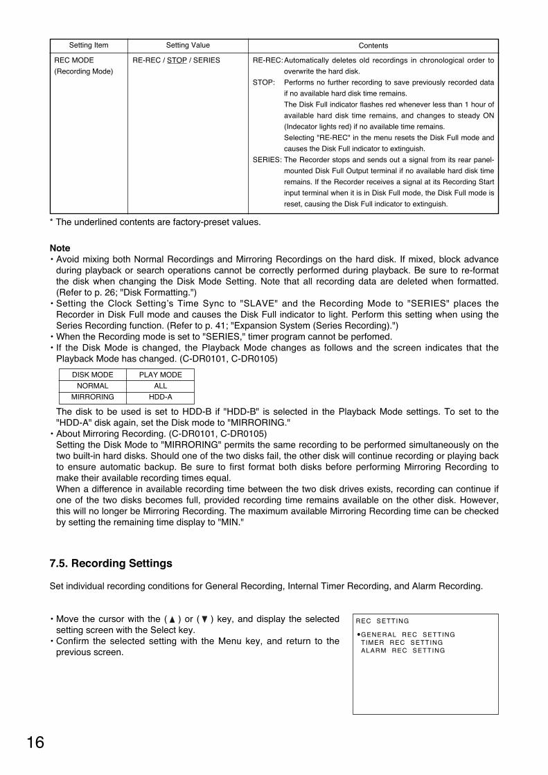
7.5. Recording Settings
Set individual recording conditions for General Recording, Internal Timer Recording, and Alarm Recording.
• Move the cursor with the ( ) or ( ) key, and display the selectedsetting screen with the Select key.
• Confirm the selected setting with the Menu key, and return to theprevious screen.
REC SETTING
•GENERAL REC SETTINGTIMER REC SETTINGALARM REC SETTING
Setting Value ContentsSetting Item
REC MODE
(Recording Mode)
RE-REC: Automatically deletes old recordings in chronological order to
overwrite the hard disk.
STOP: Performs no further recording to save previously recorded data
if no available hard disk time remains.
The Disk Full indicator flashes red whenever less than 1 hour of
available hard disk time remains, and changes to steady ON
(Indecator lights red) if no available time remains.
Selecting "RE-REC" in the menu resets the Disk Full mode and
causes the Disk Full indicator to extinguish.
SERIES: The Recorder stops and sends out a signal from its rear panel-
mounted Disk Full Output terminal if no available hard disk time
remains. If the Recorder receives a signal at its Recording Start
input terminal when it is in Disk Full mode, the Disk Full mode is
reset, causing the Disk Full indicator to extinguish.
RE-REC / STOP / SERIES
* The underlined contents are factory-preset values.

17
• Move the cursor with the ( ) or ( ) key, and press the Select Key.The Timer Schedule Screen is displayed.
• Confirm the setting with the Menu key, and return to the previousscreen.
7.5.2. Internal Timer Recording Settings
If Internal Timer Recording Settings is selected, the Timer Setting List screen is displayed. Up to 10 timer programs can be set individually. Move the cursor to the desired program and press the Select key. The Timer Schedule screen is thendisplayed.
* The underlined contents are factory-preset values.
• Move the cursor with the ( ) or ( ) key, and change setting valueswith the (–) or (+) key.
• Confirm the setting with the Menu key, and return to the previousscreen.
• Each setting item and its setting value and contents are as shown inthe table below.
7.5.1. General Recording Settings
Set the recording conditions for General Recording.
GENERAL REC SETTING
PICTURE QUALITY [LEVEL3]AUDIO [ ON]REC INTERVAL [1/30SEC]SW CTRL PERIOD [01]
Setting Value ContentsSetting Item
PICTURE QUALITY
AUDIO
REC INTERVAL
(Recording Intervals)
SW CTRL PERIOD
(Used for switching
cameras by means
of the sequential
switcher, etc.)
LEVEL1 : Angle of view 720 x 240 file size : 64KB (High Picture Quality )
LEVEL2 : Angle of view 720 x 240 file size : 40KB
LEVEL3 : Angle of view 720 x 240 file size : 32KB
LEVEL4 : Angle of view 720 x 240 file size : 24KB
LEVEL5 : Angle of view 720 x 240 file size : 16KB
(Standard Picture Quality)
ON: Records audio sound simultaneously during recording.
OFF: Records no audio sound during recording.
Sets recording intervals.
Setting the Disk Setting’s Disk Mode to "MIRRORING" limits the
maximum recording interval to 1/30 second. Even if set to "1/60 SEC," the
actual recording interval is 1/30 second, and the "1/30 SEC" indication is
displayed on the screen. (C-DR0101, C-DR0105)
Set the camera switching signal period.
The camera switching signal is provided from the Switcher Control Output
at time intervals of recording interval x switching period to switch
cameras. This setting is common to all Recording Modes of General
Recording, Internal Timer Recording, and Alarm Recording.
LEVEL1 / LEVEL2 / LEVEL3 /
LEVEL4 / LEVEL5
ON / OFF
1/60SEC / 1/30SEC / 1/15SEC /
1/10SEC / 1/5SEC / 1/3SEC /
1/2SEC / 1SEC / 2SEC / 3SEC /
5SEC /10SEC / 20SEC / 30SEC /
60SEC
01 / 02 / 03 / 04 / 05 / 10 / 15 / 20/
30 / 60
TIMER SETTING LISTSTART – END
• JAN / 01 / 04 00 : 00 ~ 10 : 00SM – W – F – 12 : 34 ~ 23 : 45––– / –– / –– –– : –– ~ –– : ––––– / –– / –– –– : –– ~ –– : ––––– / –– / –– –– : –– ~ –– : ––––– / –– / –– –– : –– ~ –– : ––––– / –– / –– –– : –– ~ –– : ––––– / –– / –– –– : –– ~ –– : ––––– / –– / –– –– : –– ~ –– : ––––– / –– / –– –– : –– ~ –– : ––

18
* The underlined contents are factory-preset values.
• Move the cursor with the ( ) or ( ) key, and change setting valueswith the (–) or (+) key.
• Confirm the setting with the Menu key, and return to the previousscreen.
• Each setting item and its setting value and contents are as shown inthe table below.
Setting Value ContentsSetting Item
DATE
(Recording Start
Date)
TIME
(Preset Times)
PICTURE QUALITY
AUDIO
REC INTERVAL
(Recording Intervals)
REC PATTERN
(Recording Pattern)
MOTION DETECT
PTN (Motion
Detection Pattern)
DAILY : Designates the Internal Timer Recording date. Timer
schedules can be set for any time between the current time to
one year ahead. The day of the week is automatically
displayed. Programs are automatically deleted after their
preset times are reached.
WEEKLY: Designates two or more days of the week. If all days from
Sunday to Saturday are designated, recording is performed
every day.
CANCEL : Cancels preprogrammed settings.
Designates the timer operating period in minutes. If the same timer preset
time is duplicated, the "TIME SETTING ERROR" indication is displayed
on the screen to the right side of the program number, invalidating the
date setting. In such cases, correctly reset the time. Note that the timer
operating period cannot be set unless the complete time (hour and
minute) is entered.
LEVEL1 : Angle of view 720 x 240 file size : 64KB (High Picture Quality)
LEVEL2 : Angle of view 720 x 240 file size : 40KB
LEVEL3 : Angle of view 720 x 240 file size : 32KB
LEVEL4 : Angle of view 720 x 240 file size : 24KB
LEVEL5 : Angle of view 720 x 240 file size : 16KB
(Standard Picture Quality)
ON: Records audio sound simultaneously during recording.
OFF: Records no audio sound during recording.
Designates the Recording intervals.
Setting the Disk Setting’s Disk Mode to "MIRRORING" limits the
maximum recording interval to 1/30 second. Even if set to "1/60 SEC," the
actual recording interval is 1/30 second, and the "1/30 SEC" indication is
displayed on the screen (C-DR0101, C-DR0105)
Transmits a Pattern Selection command from the RS-232C connector
when the preset timer operating time is reached.
Transmits a Pattern Selection command from the RS-232C connector
when the preset timer operating time is reached.
DAILY / WEEKLY / CANCEL
LEVEL1 / LEVEL2 / LEVEL3 /
LEVEL4 / LEVEL5
ON / OFF
1/60SEC / 1/30SEC / 1/15SEC /
1/10SEC / 1/5SEC / 1/3SEC /
1/2SEC / 1SEC / 2SEC / 3SEC /
5SEC /10SEC / 20SEC / 30SEC /
60SEC
1 / 2
1 / 2
TIMER SETTING 01
DATE[DAILY] THU JAN / 01 / 04
TIME 00 : 00 – 10 : 00PICTURE QUALITY [LEVEL3]AUDIO [ON]REC INTERVAL [1/30SEC]REC PATTERN [1]MOTION DETECT PTN [1]
Timer Schedule Screen Settings
NotePattern 1 command of both the Recording Pattern and Motion Detection Pattern is transmitted from the RS-232C connector at times other than timer set times such as power-on, after Internal Timer Recordingcompletion, and during General Recording.Recording Pattern and Motion Detection Pattern are functions available to the Multi-switcher (C-MS91D, C-MS161D). For more information on these functions, refer to the instruction manual for the Multi-switcher.
Program No
ALARM REC SETTING
ALARM SETTING [ VALID]ALARM IN MODE [LEVEL]PRE–ALARM [00SEC]ALARM PERIOD [ 1MIN]POST–ALARM [00SEC]PICTURE QUALITY [LEVEL3]AUDIO [ ON]REC INTERVAL [1/30SEC]BUZZER [ ON]ALARM OUT [DURING REC]
19
Setting Value ContentsSetting Item
ALARM SETTING
ALARM IN MODE
(Alarm Input Mode)
PRE-ALARM
ALARM PERIOD
POST-ALARM
PICTURE QUALITY
AUDIO
REC INTERVAL
(Recording Interval)
BUZZER
ALARM OUT (Alarm
Output Periods )
VALID : Validates alarm settings. (Alarm standby mode)
VAL REC : Validates alarm settings only during recording.
INVALID : Invalidates alarm settings. (Rejects alarm inputs.)
EDGE : Performs recording during preset Pre-alarm and Alarm
Recording periods
LEVEL : Performs recording during preset Pre-alarm Recording, Alarm
input, and Post-alarm Recording periods.
Performs retroactive recording to a preset time period before alarm
activation.
Performs recording during a preset alarm input period following alarm
activation when the Alarm Input Mode is set to EDGE. (Refer to p. 20;
"About the Alarm Input Mode")
Performs recording during a preset Post-alarm recording period following
the end of alarm activation when the alarm input mode is set to "LEVEL."
LEVEL1 : Angle of view 720 x 240; file size : 64KB (High Picture Quality)
LEVEL2 : Angle of view 720 x 240; file size : 40KB
LEVEL3 : Angle of view 720 x 240; file size : 32KB
LEVEL4 : Angle of view 720 x 240; file size : 24KB
LEVEL5 : Angle of view 720 x 240; file size : 16KB
(Standard Picture Quality)
ON: Records audio sound simultaneously during recording.
OFF: Records no audio sound during recording.
Sets the Recording intervals.
Setting the Disk Mode of Disk Settings to "MIRRORING" limits the
maximum recording interval to 1/30 second. Even if set to "1/60 SEC", the
actual recording interval is 1/30 second, and the "1/30 SEC "indication is
displayed on the screen (C-DR0101, C-DR0105)
ON: Sounds a buzzer when an alarm is activated. Pressing the Buzzer
Reset key stops buzzer operation.
OFF: Sounds no buzzer during alarm activation.
The Alarm Output terminal shorts to ground during a set period of time
following alarm activation.
VALID / VAL REC / INVALID
EDGE / LEVEL
00SEC/ 10SEC/ 15SEC/ 20SEC /
30SEC/ 1MIN/ 2MIN/ 5MIN
10SEC/ 15SEC/ 20SEC/ 30SEC/
1MIN/ 2MIN/ 3MIN/ 4MIN/ 5MIN/
10MIN
00SEC/ 10SEC/ 15SEC/ 20SEC/
30SEC/ 1MIN/ 2MIN/ 5MIN
LEVEL1 / LEVEL2 / LEVEL3 /
LEVEL4 / LEVEL5
ON / OFF
1/60SEC / 1/30SEC / 1/15SEC /
1/10SEC / 1/5SEC / 1/3SEC /
1/2SEC / 1SEC /
ON / OFF
DURING REC / 1SEC
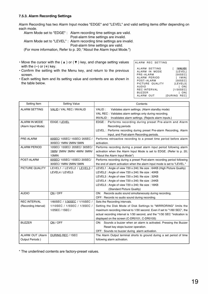
• Move the cursor with the ( ) or ( ) key, and change setting valueswith the (–) or (+) key.
• Confirm the setting with the Menu key, and return to the previousscreen.
• Each setting item and its setting value and contents are as shown inthe table below.
7.5.3. Alarm Recording Settings
Alarm Recording has two Alarm Input modes "EDGE" and "LEVEL" and valid setting items differ depending oneach mode.
Alarm Mode set to "EDGE" : Alarm recording time settings are valid.Post-alarm time settings are invalid.
Alarm Mode set to "LEVEL" : Alarm recording time settings are invalid.Post-alarm time settings are valid.
(For more information, Refer to p. 20; "About the Alarm Input Mode.")
* The underlined contents are factory-preset values.

20
Alarm Input
Recording Status
Alarm Output
ON
Recording
When an alarm output duration is set to 1 second:
1 Sec
Pre-alarm Period Alarm Recording Period
Alarm Input
Recording Status
Alarm Output
ON
Recording
Pre-alarm Period
When an alarm output is provided during alarm recording:
Recording Period Post-alarm Period
7.5.4. About the Alarm Input Mode
The Alarm Input mode for Alarm Recording can be set to "EDGE" or "LEVEL."Each input mode operates as follows:
[Recording period when input mode is set to "EDGE"]Performs continuous recording during Pre-alarm Recording and Alarm Recording Periods.
[Recording period when input mode is set to "LEVEL"]Provides continuous recording during periods of time of Pre-alarm Recording, alarm activation, and Post-alarm Recording.
NotePre-alarm recording is operated by the Alarm Recording Setting. It does not operate even if an alarm isactivated during General Recording or Internal Timer Recording since they are operated by their own settings.

21
7.6. Screen Display Settings
The Disk Mode Display item is displayed when the C-DR0101 and C-DR0105 is used.Set whether to display or hide on-screen characters during playback or recording.
• Move the cursor with the ( ) or ( ) key, and change setting valueswith the (–) or (+) key.
• Confirm the setting with the Menu key, and return to the previousscreen.
• Each setting item and its setting value and contents are as shown inthe table below.
ON–SCREEN DISP SETTING
PICTURE QUALITY [DISP]AUDIO [DISP]REC MODE [DISP]RECORDING [DISP]PLAYING [DISP]REMAINING TIME [ DISP]DATE [DISP]TIME [DISP]TIME DISP POS [UPPER L]DISK MODE [DISP]
Setting Value ContentsSetting Item
PICTURE QUALITY
AUDIO
REC MODE
(Recording Mode)
RECORDING
(Recording Display)
PLAYING (Playing
back Display)
REMAINING TIME
(Remaining Time
Display)
DATE
(Date Display)
TIME
(Time Display)
TIME DISP POS
(Date/Time Display
Position)
DISK MODE
(Disk Mode Display)
Displays or hides the picture quality indicator during recording or
playback.
Displays or hides the audio indicator when Audio is set to ON during
recording.
Displays or hides the overwrite recording setting status indicator during
recording.
Displays or hides the recording mode status indicator during recording.
Displays or hides the playback speed, playback direction, and pause
status during playback.
Displays or hides Digital Video Recorder's remaining time. The remaining
hard disk time is calculated from the currently recorded picture quality and
recording interval when the Disk Settings Recording Mode is set to
"STOP" or "SERIES."
Displays or hides Digital Video Recorder's remaining time. The remaining
hard disk time designated is calculated from the currently recorded picture
quality and recording interval when the Disk Settings Recording Mode is
set to "STOP" or "SERIES." (C-DR0101, C-DR0105)
Displays or hides the current date during recording, and the recorded date
during playback.
Displays or hides the current time during recording, and the recorded time
during playback.
Sets the date/time display position. Other display positions also change
depending on the date/time display position.
Displays or hides the disk connection status indicator. (C-DR0101, C-
DR0105)
DISP / HIDE
DISP / HIDE
DISP / HIDE
DISP / HIDE
DISP / HIDE
Disk Mode set to "NORMAL":
DISP / HIDE
Disk Mode set to "MIRRORING":
MAX / MIN / HDD-A /
HDD-B / HIDE
DISP / HIDE
DISP / HIDE
UPPER L/ UPPER C/ UPPER R/
LOWER L/ LOWER C/ LOWER R
DISP / HIDE
* The underlined contents are factory-preset values.

22
• Pressing the Menu key returns the display to the normal operation screen if the password is enteredcorrectly. If the wrong password is entered, the display returns to the Main Menu screen. In such cases,perform the settings again.
• Entering the password correctly displays the following screen andvalidates key locking.
KEY LOCK
KEY LOCK VALIDATED.
• The following screen is displayed if the wrong password is entered. KEY LOCK
INVALID PASSWORD
7.7.1 Key Lock Release
• Hold down the Menu key for at least 1 second on the normaloperation screen.
• The Key Lock Release screen is displayed.
KEY LOCK RELEASE
ENTER A PASSWORD.
[ _ ]
• Entering the password correctly returns the display to the Main Menuscreen.
• If the wrong password is entered, the "INVALID PASSWORD"indication is displayed as in the case of the Key Lock setting. Sincethe display returns to the normal screen if the Menu key is pressed,perform release operation.
MAIN MENU
• PLAY SETTINGCLOCK SETTINGDISK SETTINGREC SETTINGON–SCREEN DISP SETTINGKEY LOCKCOMMUNICATION SETTINGLOG DISPLAYSYSTEM MAINTENANCE
7.7. Key Lock
This function validates key locking. If validated, any key other than the Menu key is not accepted. Pressing keys other than the Menu key soundsa warning tone.
KEY LOCK
ENTER A PASSWORD.
[ _ ]
• The password input screen is displayed if Key Lock is selected on themain menu screen. Press the (–), (+), ( ), and ( ) keys (in thatorder) as a password. The " " indication is displayed on the screento confirm each key entry as the keys are pressed.
NoteThe password and the key entry order cannot be changed.

NETWORK SETTING
IP ADDRESS192. 168. 000. 001
SUBNET MASK255. 255. 255. 000
DEFAULT GATEWAY000. 000. 000. 000
COMMUNICATION SETTING
RS232C BAUD RATE [38400]RS232C FLOW CTRL [OFF]NETWORK SETTINGSWITCHER SYNC
[ OFF]
23
• Pressing the Menu key after the setting displays the confirmationmessage in the lower part of the screen if the entered IP address isdifferent from the current IP address.
• Holding down the Select key for at least 1 second on the confirmationmessage display screen displays the setting save screen.
• Press the Menu key if performing no setting. The display returns tothe normal communication setting screen.
NETWORK SETTING
IP ADDRESS192. 168. 000. 001
SUBNET MASK255. 255. 255. 000
DEFAULT GATEWAY000. 000. 000. 000
SET THIS SETTING. OK?YES : SELECT KEY 1SEC
NO : MENU KEY
NETWORK SETTING
SAVING SET DATA NOW.PLEASE WAIT FOR A WHILE.
Setting Value ContentsSetting Item
RS232C BAUD
RATE
RS232C FLOW
CTRL
SWITCHER SYNC
(Switcher
Synchronization) *1
Sets the transmission rate.
Sets Flow Control RTS or CTS
ON : Controls the switcher through the RS-232C interface.
OFF : Controls no switcher
TIME SYNC : Only Time Synchronization can be controlled through the
RS-232C interface.
9600 / 19200 / 38400 (bps)
ON / OFF
ON / OFF / TIME SYNC
7.8.1. Network Settings
The Network Setting screen is displayed if Network Settings is selected on the communication setting screen.Perform settings that are appropriate for the network.
• Move the cursor with the ( ) or ( ) key, and change setting valueswith the (–) or (+) key.
* The underlined contents are factory-preset values.
7.8. Communication Settings
Set the transmission rate and whether or not to use flow control in RS-232C communications. Also set the IPaddress, etc. to be used in the Ethernet network.
• Move the cursor with the ( ) or ( ) key, and change setting valueswith the (–) or (+) key.
• Confirm the setting with the Menu key, and return to the previousscreen.
Note*1 Recording Pattern, Motion Detection Pattern, Camera/ VCR mode selection, and Time Synchronization
switcher functions can all be controlled by the Digital Video Recorder. However, when syncronizing theswitcher's clock from the Recorder, set the Recorder's clock Time Synchronization setting to "MASTER."Time synhronization cannot be performed if set to "SLAVE."

24
7.9.2 Alarm Recording Logs (Alarm Rec Log)
Logs Alarm Recording start and end times, and displays from the latest log. Up to 500 logs are saved and oldlogs are deleted in chronological order when this limit is exceeded.
• The display scrolls in page units (1 screen units) as the ( ) or ( )key is pressed.
• Return to the previous screen with the Menu key.
ALARM REC LOG
JAN/ 02/ 04 07: 00: 00 END
JAN/ 02/ 04 00: 00: 00START
JAN/ 01/ 04 18: 00: 00END
JAN/ 01/ 04 09: 00: 00START
JAN/ 01/ 04 07: 00: 00END
7.9. Log Display
Log indications include General Recording Log, Alarm Recording Log, and Failure Log.
• Move the cursor with the ( ) or ( ) key, and display Log Screenwith the Select key.
• Return to the previous screen with the Menu key.
7.9.1. General/ Timer Recording Logs (General/ Timer Rec Log)
Logs start and end times of both General and Internal Timer Recordings, and displays from the latest log. Upto 100 logs are saved, and old logs are deleted in chronological order when this limit is exceeded.
• The display scrolls in page units (1 screen units) as the ( ) or ( )key is pressed.
• Return to the previous screen with the Menu key.
LOG DISPLAY
• GENERAL/ TIMER REC LOGALARM REC LOGFAILURE LOG
GENERAL/ TIMER REC LOG
JAN/ 02/ 04 07: 00: 00 T IMER REC END
JAN/ 02/ 04 00: 00: 00TIMER REC START
JAN/ 01/ 04 18: 00: 00REC END
JAN/ 01/ 04 09: 00: 00REC START
JAN/ 01/ 04 07: 00: 00TIMER REC END
• The figure at right is displayed after saving completion.• Pressing the Menu key returns the display to the communication
setting menu screen.• Switch the power OFF and back ON again to validate the network
setting. (Turn off and on the rear-panel mounted Main Power switch.)NoteNetwork camera’s settings are not enabled at the front-mountedStandby Key operation.
NETWORK SETTING
NETWORK SETTING CHANGED.TURN POWER OFF AND ON TOVALIDATE THE SETTING.
PRESS MENU KEYTO RETURN.

25
7.10.1. Menu Default Settings
• Holding down the Select key for at least 1 second clears saved menusetting contents and log information, initializing settings to factory-preset status. However, clock settings and network settings areretained.
• Return to the previous screen with the Menu key.
MENU DEFAULT SETTING
SET TO DEFAULT?
YES : SELECT KEY 1SECNO : MENU KEY
7.9.3. Failure Logs
Logs detection times and contents for the various different failure modes that can occur in the Digital VideoRecorder, and displays from the latest log. Up to 100 logs are saved and old logs are deleted in chronologicalorder when this limit is exceeded.
• The display scrolls in page units (1 screen units) as the ( ) or ( )key is pressed.
• Return to the previous screen with the Menu key.
NoteThe current log display does not change even if a new log is added during display. To confirm the added log, change the page or return to the log item selection screen to display the log again. All logs are deleted if Menu Default Settings of System Maintenance is performed.
7.10. System Maintenance
Performs menu default settings or format the hard disk.
• Move the cursor with the ( ) or ( ) key, and confirm the Item withthe Select key.
• Return to the previous screen with the Menu key.
FAILURE LOG
JAN/ 02/ 04 07: 00: 00 VIDEO FAILURE
JAN/ 02/ 04 00: 00: 00DISK FAILURE
JAN/ 01/ 04 18: 00: 00VIDEO FAILURE
JAN/ 01/ 04 09: 00: 00FAN FAILURE
JAN/ 01/ 04 07: 00: 00DISK FAILURE
SYSTEM MAINTENANCE
• MENU DEFAULT SETTINGDISK FORMATTING
ContentsDisplay Item
VIDEO FAILURE
DISK FAILURE
FAN FAILURE
Displays this indication when a video signal cutoff (Video Loss) is
detected during recording.
Displays this indication when a disk error is detected.
Displays this indication when fan operation stops.

26
7.10.2. Disk Formatting
This function initializes the hard disk. If initialized, all previously recorded contents are deleted. However,setting contents and logs are retained. Hard disks to be formatted can be selected when the C-DR0101 andC-DR0105 is used.
• Move the cursor with the ( ) or ( ) key, and change setting valueswith the (–) or (+) key.
• Hold down the Select key for at least 1 second to start formatting.• Return to the previous screen with the Menu key.
Formatting is started by holding down the Select key for at least 1second again after the reconfirmation message is displayed. Pressingthe Menu key returns the display to the system maintenance screenwithout formatting.
The disk error message is displayed if a disk error occurs during formatting.
DISK FORMATTING
DISK FORMATTING [ ALL]
FORMAT DISKS?YES : SELECT KEY 1SEC
NO : MENU KEY
DISK FORMATTING
ARE YOU SURE?
YES : SELECT KEY 1SECNO : MENU KEY
(C-DR0101, C-DR0105)ContentsSetting Items
HDD-A
HDD-B
ALL
Formats Hard Disk A
Formats Hard Disk B
Formats all set hard disks.

27
After system check completion, the Standby key changes from flashing to steady ON, allowing camera imagesto be displayed.
NoteWhen the Recorder is used for the first time or when the power was switched off for a long period of time, thedate and time could not be correctly displayed. Perform the clock setting before use. (Refer to p. 14; "ClockSettings.")
8. DIGITAL VIDEO RECORDER ACTIVATION AND TERMINATION
8.1. Recorder's Activation
The switch and key shown in the following figures are used in operation.
1. Connect each component correctly. (Refer to p. 40; "Connections.")
2. Set the rear-panel mounted Main Power switch to the ON position.The Standby key flashes green for 5 seconds while settings are initialized. Thereafter, the Recorder isplaced in standby mode. The Standby key flashes every 5 seconds while in standby mode.
NoteDo not turn off the Main Power switch while the Standby key is flashing. Ensure that the Recorder is in thestandby mode when turning off the Main Power switch. Logged data could be damaged or lost if the main power is switched off during initialization (while accessingthe hard disk).
3. Press the Standby key while the Recorder is in standby mode. The screen automatically changes as shown below.The Standby key flashes green during a system check.
AC MAINS MAIN POWER
ON
OFF
IN OUT IN OUT
VIDEO SW VIDEO IN
OUT
AUDIO GND GND100BASE–TX
ALARM RESET OUTALARM INSW CTRL OUT
TIME SYNC INREC STOP IN
REC START INALARM RESET IN
TIME SYNC OUTALARM OUT
FAILURE OUTDISK FULL OUT
RS–232C
Main Power Switch
DIGITAL VIDEO RECORDER
DISK FULL/ FAILURE
ALARMRESET
BUZZER STOP
SEARCHMENUSELECT
BLOCK
PLAYSTOPPLAYPAUSE
REVERSEPLAYRECTIMER
FRAME FRAME
OUTPUT
VIDEO AUDIO
Standby Key
SYSTEM CHECK COMPLETED
V e r .
SYSTEM CHECK IN PROGRESS
PLEASE WAIT
28
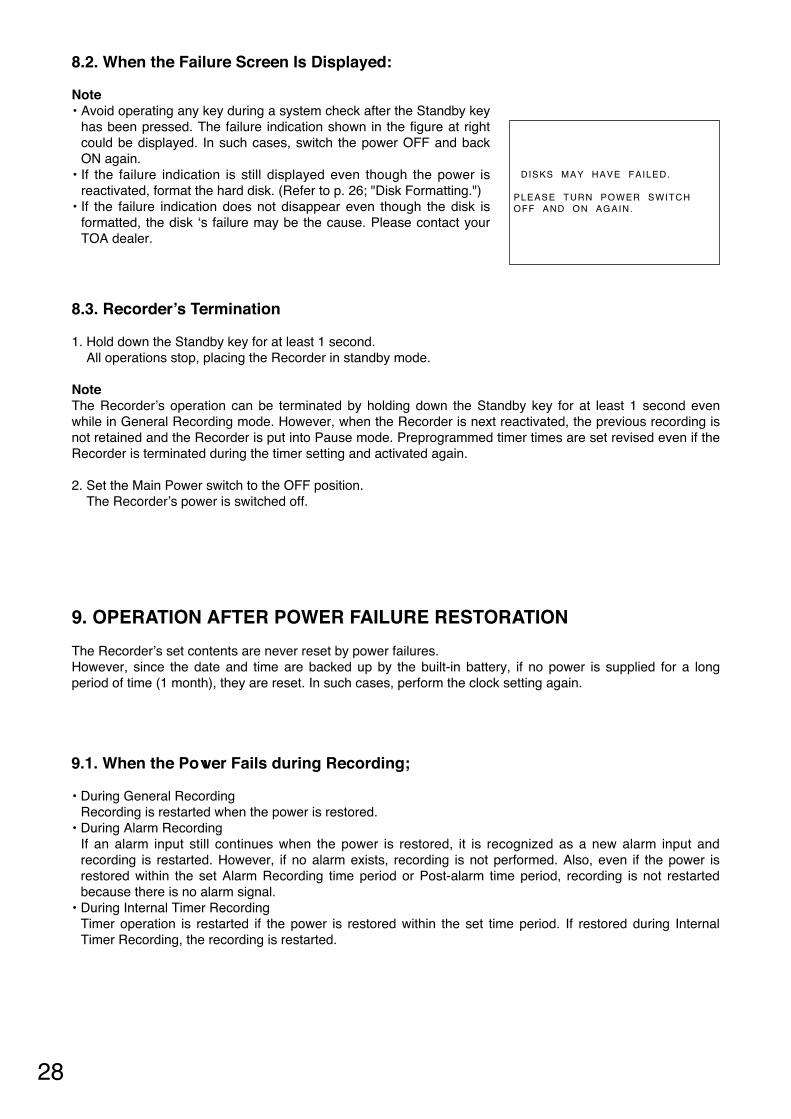
8.2. When the Failure Screen Is Displayed:
Note• Avoid operating any key during a system check after the Standby key
has been pressed. The failure indication shown in the figure at rightcould be displayed. In such cases, switch the power OFF and backON again.
• If the failure indication is still displayed even though the power isreactivated, format the hard disk. (Refer to p. 26; "Disk Formatting.")
• If the failure indication does not disappear even though the disk isformatted, the disk ‘s failure may be the cause. Please contact yourTOA dealer.
DISKS MAY HAVE FAILED.
PLEASE TURN POWER SWITCHOFF AND ON AGAIN.
8.3. Recorder’s Termination
1. Hold down the Standby key for at least 1 second. All operations stop, placing the Recorder in standby mode.
NoteThe Recorder’s operation can be terminated by holding down the Standby key for at least 1 second evenwhile in General Recording mode. However, when the Recorder is next reactivated, the previous recording isnot retained and the Recorder is put into Pause mode. Preprogrammed timer times are set revised even if theRecorder is terminated during the timer setting and activated again.
2. Set the Main Power switch to the OFF position. The Recorder’s power is switched off.
9. OPERATION AFTER POWER FAILURE RESTORATION
The Recorder’s set contents are never reset by power failures. However, since the date and time are backed up by the built-in battery, if no power is supplied for a longperiod of time (1 month), they are reset. In such cases, perform the clock setting again.
9.1. When the Power Fails during Recording;
• During General RecordingRecording is restarted when the power is restored.
• During Alarm RecordingIf an alarm input still continues when the power is restored, it is recognized as a new alarm input andrecording is restarted. However, if no alarm exists, recording is not performed. Also, even if the power isrestored within the set Alarm Recording time period or Post-alarm time period, recording is not restartedbecause there is no alarm signal.
• During Internal Timer RecordingTimer operation is restarted if the power is restored within the set time period. If restored during InternalTimer Recording, the recording is restarted.

29
10. RECORDING
10.1. Type of Recording
Recording modes include General Recording, Internal Timer Recording, and Alarm Recording. Each recordingmode permits the picture quality and recording interval to be set individually. (Refer to p. 17; "GeneralRecording Settings.") In the Digital Video Recorder, recorded data from the start to the end of each recordingis handled as a single recorded block.
10.1.1. Recording Priorities
The order of Recording Priority is as shown below.
Recording End
General Recording
Alarm Recording
Internal Timer Recording
Timer Key pressed
Alarm Input Alarm Input Alarm Input
Alarm End Rec. key pressed Alarm End
• RECLEVEL3 1 / 60
THU JAN / 01 / 0400 : 00 : 00
00 : 00 : 00M AB F
1
2 3 4 5 6 7
8
9
10* *
10.2. Screen Display during Recording
The screen display setting is factory-preset to "DISP." (Refer to p. 21; "Screen Display Settings".)
* C-DR0101, C-DR0105
High LowOrder of Priority
Type of RecordingGeneral RecodingAlarm Recoding
Internal Timer Recording
Lower-priority recording stops whenever higher-priority recording is commenced. The following figure showsan example of recording operation that varies whenever recording of different priority levels is commenced.
NoteInternal Timer Recording does not operate even if the Timer key is pressed during General or Alarmrecording. Pressing the Recording ( / ) key during a timer setting cancels the timer setting. To resume thetimer setting, first stop recording and press the Timer key.
Indicates the recording status. (Refer to p. 17; "General Recording Settings".)
• REC: Represents General Recording is in progress.
• TIMER: Represents Internal Timer Recording is in progress.
• ALARM: Represents Alarm Recording is in progress.
Indicates the recording picture quality.Can be set to Levels 1 – 5. LEVEL 1 provides the highest resolution display.
2
1

30
Indicates the recording interval.General Recording and Internal Timer Recording : 1/60 – 60 secondsAlarm Recording : 1/60 – 1 seconds
Note• Even if the Recording Setting’s Recording Interval is set to "1/60 SEC," Mirroring Recording is performed at
the recording interval of 1/30 second. (The on-screen interval indication is also "1/30 SEC" in MirroringRecording.) (Refer to p. 17; "General Recording Settings.")
• The higher the picture quality (resolution) and the shorter the recording interval, the shorter the possiblerecording time. Conversely, the lower the picture quality and the longer the recording interval, the longer thepossible recording time. (Refer to p. 45; "Recording Time Table.")
Indicates whether or not to use the Audio recording function.: Audio recording ON (enabled)
No indication : Audio recording OFF (disabled)
Indicates the hard disk Recording Mode. (Refer to p. 15; "Disk Settings.")Re-Rec ModeStop ModeSeries Mode
• Re-Rec Mode : Overwrites old hard disk recordings in chronological order even when no available hard disktime remains.
• Stop Mode : Stops video recording when no available hard disk time remains. • Series Mode : Stops video recording when no available hard disk time remains, and sends out a signal
from the Control Terminal’s Disk Full output, allowing other series-connected Digital VideoRecorder to start recording. The slave Digital Video Recorder starts recording when itreceives a signal at its Recording Start input terminal even if its hard disk becomes full.(Refer to p. 41; "Expansion System (Series Recording).")
Indicates the Disk Mode. (C-DR0101, C-DR0105) (Refer to p. 15, "Disk Settings".)No indication : Normal RecordingM : Mirroring Recording
• About Normal and Mirroring recordingsThe C-DR0101 and C-DR0105 has two built-in hard disks. Setting the Disk Mode to "NORMAL" permits camera images to be recorded on the second hard disk whenthe first hard disk becomes full. Setting the Disk Mode to "MIRRORING" permits the same recording to be simultaneously performed on thetwo hard disks. Even if one of the two disks fails, recording and playback can still be performed using theother disk.
Indicates the hard disk recognition status. (C-DR0101, C-DR0105)Characters are reversed for the hard disk in recording mode.The "X" indication is displayed when the hard disk fails.
NoteEven if the Screen Display Setting’s Disk Mode Indication is set to "HIDE," the "X" indication is displayed when the hard disk fails.
Indicates the remaining hard disk recording time calculated from the picture quality and recording intervalof current recording.If the Disk Setting’s Recording Mode is set to "RE-REC", the remaining hard disk recording time is notdisplayed.(Refer to p. 15; "Disk Settings".)
Indicates the current date and time.
The "F" indication flashes when the fan fails. Cannot be set to "HIDE" in Screen Display Settings.
10
9
8
7
6
5
4
3

31
10.5. Performing Internal Timer Recording (Refer to p. 17; "Internal Timer Recording Settings)
NoteBe sure to perform date and time settings before recording. (Refer to p. 14; "Clock Settings".)
1. Press the Timer key.The Digital Video Recorder is placed in Internal Timer Recordingstandby mode, and the Timer key lights green.
2. When the preset time is reached or if the key is pressed within thepreset period, the Recording key lights red and recording is started.If "DISP" has been selected in Screen Display Settings, setting datais displayed on the monitor, and the "TIMER" indication is displayedfor recording status.
10.4. Performing General Recording (Refer to p. 17; "General Recording Settings)
NoteBe sure to perform time and date settings before recording. (Refer to p. 14; "Clock Settings")
1. Press the Recording key ( / ) to start General Recording.When recording is started, the Recording key lights red. If "DISP" has been selected in Screen Display Settings, setting datais displayed on the monitor and the Recording indication is displayedfor recording status.
NoteWhen the Disk Setting Recording Mode has been set to "STOP" or"SERIES," the Disk Full indicator flashes if less than 1 hour of availablehard disk time remains. If no available hard disk time remains, the DiskFull indicator changes to steady ON and recording stops.
2. Hold down the Recording key ( / ) for at least 1 second to stop recording. The illuminated Recording key extinguishes.
NoteIf an alarm is activated during General Recording performance while in alarm standby mode, the GeneralRecording is interrupted and switched over to Alarm Recording. The General Recording is automaticallyrestored after Alarm Recording completion.
THU JAN/ 01/ 0400 : 00 : 00
• RECLEVEL3 1 /60 M : AB F
THU JAN/ 01/ 0400 : 00 : 00
• TIMERLEVEL3 1 /60 M : AB F
10.3. The Keys to Be Used in Recording
The following keys are used in recording:
DIGITAL VIDEO RECORDER
DISK FULL/ FAILURE
ALARMRESET
BUZZER STOP
SEARCHMENUSELECT
BLOCK
PLAYSTOPPLAYPAUSE
REVERSEPLAYRECTIMER
FRAME FRAME
OUTPUT
VIDEO AUDIO
Timer Key Recording Key Buzzer Stop Key

32
10.6. Performing Alarm Recording (Refer to p. 19; "Alarm Recording Settings)
Note• Be sure to perform date and time settings before recording. (Refer to p. 14; "Clock Settings".)• Be sure to set the Alarm Recording Setting’s Alarm Setting to "VALID" when performing Alarm Recording.
This places the Digital Video Recorder in alarm standby mode. • The setting is factory-preset to "VALID."
1. A buzzer is sounded and the Buzzer stop key flashes red when an alarm signal is received. At the sametime, the Recording key lights red and recording is started. TheBuzzer stop key continues flashing red during Alarm Recording.
• If "DISP" has been selected in Screen Display Settings, setting data isdisplayed on the monitor, and the "ALARM" indication is displayed forrecording status.
• Pressing the Buzzer stop key during buzzer output stops the buzzer.Whether or not to sound a buzzer can be set by selecting ON or OFFin Alarm Recording Settings.
• Alarm Recording provides an open collector signal from the AlarmOutput Terminal. An alarm output duration can be set to "1 SEC" or"DURING REC" in Alarm Recording Settings.
2. Recording stops when the end of the Preset Alarm Recording Period is reached. The illuminated Recordingkey extinguishes, however the Alarm Reset key remains lit. To reset Alarm Recording before the PresetAlarm Dcording Period is started, hold down the Alarm Reset key for at least 1 second.
Note• Pressing the Recording key ( / ) during Alarm Recording resets Alarm Recording, and switches it over to
General Recording. However, the Alarm Reset key continuously lights red to indicate that an alarm has beenactivated.
• To extinguish the illuminated Alarm Reset key, hold down the Alarm Reset key for at least 1 second. • If the Alarm Recording’s Alarm Settings is set to "VAL REC," alarm signals are only accepted while
recording is in progress. Alarm inputs can be only accepted during the necessary surveillance period bycombining both Alarm and Internal Timer recordings.
• If the Alarm Recording’s Alarm Settings is set to "INVALID," any alarm input is not accepted. • If other alarms are activated during Alarm Recording, the preset alarm time is initialized to make the
recording period longer. In this case, the number of recorded blocks is one.
THU JAN/ 01/ 0400 : 00 : 00
• ALARMLEVEL3 1 /60 M : AB F
3. Recording stops when the end of the preset recording period is reached. The illuminated Recording key extinguishes.
Note• When the Disk Setting Recording Mode is set to "STOP," recording stops if no available hard disk time
remains. • When the Recording mode is set to "SERIES," timer program cannot be perfomed.• When an alarm is activated during Internal Timer Recording, the Internal Timer Recording is interrupted, and
automatically restored after Alarm Recording completion. • Pressing the Recording key ( / ) during Internal Timer Recording resets Internal Timer Recording, and
switches it over to General Recording.
4. To cancel Internal Timer Recording, hold down the Timer key for at least 1 second. The illuminated Timerkey extinguishes.

33
11. PLAYBACK
11.1. Type of Playback
The Digital Video Recorder features the simultaneous recording/playback function that permits recordedimages to be played back without stopping recording. The types of playback include Playback, ReversePlayback, Fast Forward Playback, Fast Reverse Playback, Forward Frame Playback, and Reverse FramePlayback.
Note• When the Playback Setting’s Simultaneous Recording/Playback is set to "DISALLOW," playback cannot be
performed during recording. Only recording or playback can be performed. • Playback performance could be degraded during simultaneous recording/playback operation.
x 2 •LEVEL3 1 / 60
THU JAN / 01 / 0400 : 00 : 00
M A F
1
2
3 4 5
6
7 8* *
Indicates playback mode.
: Fast Reverse Playback: Fast Forward Playback: Reverse Playback: Playback: Pause
• Pressing the Playback key ( ) during playback (or the Reverse Playback key ( ) during Reverseplayback) changes the mode to Fast Forward playback (Fast Reverse playback during Reverse playback).The "x2", "x4" or "x8" indication is displayed on the screen to indicate the playback speed.
• Pressing the Playback key ( ) or the Reverse Playback key ( ) during still picture playback (while inpause mode) changes the mode to Forward or Reverse Frame playback. Holding down the key performs acontinuous frame-by-frame playback of the recorded image.
Indicates the recording picture quality. Can be set to Levels 1 – 5. Quality increases as the number decreases.Indicates the recording interval. General Recording, Internal Timer Recording : 1/60 – 60 secondsAlarm Recording : 1/60 – 1 secondsIndicates an attribute of Mirroring Recording. (C-DR0101, C-DR0105)No indication : Data other than Mirroring Recording dataM : Mirroring Recording dataIndicates the currently-used hard disk. (C-DR0101, C-DR0105)A : Playback of Hard disk AB : Playback of Hard disk B Indicates recording dates and times. The ( ) indication is displayed when recording is also performed simultaneously with playback.The "F" indication flashes when the fan fails. This indication cannot be set to "HIDE" in Screen Display Settings.
876
5
4
3
2
1
11.2. Screen Display during Playback
Screen Display Settings is factory-preset to "DISP." (Refer to p. 21; "Screen Display Settings.")
* C-DR0101, C-DR0105

34
11.4. Performing Playback
1. Press the Playback key ( ) to start playback. The Playback key lights green when playback is started. If Screen Display Settings has been set to "DISP," setting data is displayed on the monitor, and the"Playback" indication is displayed for playback status.
2. Press the Playback Stop key ( ) to stop playback. The illuminated Playback key extinguishes.
11.5. Performing Various Playback Fanctions
11.5.1. Reverse Playback
Press the Reverse Playback key ( ) to perform playback in the reverse direction. The Reverse Playback key lights green when Reverse playback is started. If Screen Display Settings has been set to "DISP," setting data is displayed on the monitor, and the "ReversePlayback" indication is displayed for playback status.
11.5.2. Fast Forward Playback and Fast Reverse Playback
Pressing the Playback key ( ) during playback (or the Reverse Playback key ( ) during Reverse playback)changes the playback mode to Fast Forward (or to Fast Reverse playback if pressed during Reverseplayback). The playback speed changes as the key is pressed.
Playback speed: Original speed Twofold speed (x2) Fourfold speed (x4) Eightfold speed (x8)
NotePlayback may not be performed at the indicated speed depending on the hard disk performance, such asaccess times.
11.5.3. Playback Pause (Still Picture)
1. Pressing the Pause key ( ) during playback or Reverse playback suspends playback operation, causingthe Pause key to light green. If Screen Display Settings has been set to "DISP," setting data is displayed on the monitor, and the "Pause"indication is displayed while in pause mode.
DIGITAL VIDEO RECORDER
DISK FULL/ FAILURE
ALARMRESET
BUZZER STOP
SEARCHMENUSELECT
BLOCK
PLAYSTOPPLAYPAUSE
REVERSEPLAYRECTIMER
FRAME FRAME
OUTPUT
VIDEO AUDIO
Reverse Playback key
Pause key Playback key
Playback Stop key
Block Shift key
11.3. The Keys to Be Used in Playback
The following keys are used in playback.Reverse Playback key, Pause key, Playback key, Playback Stop key, Block Shift key
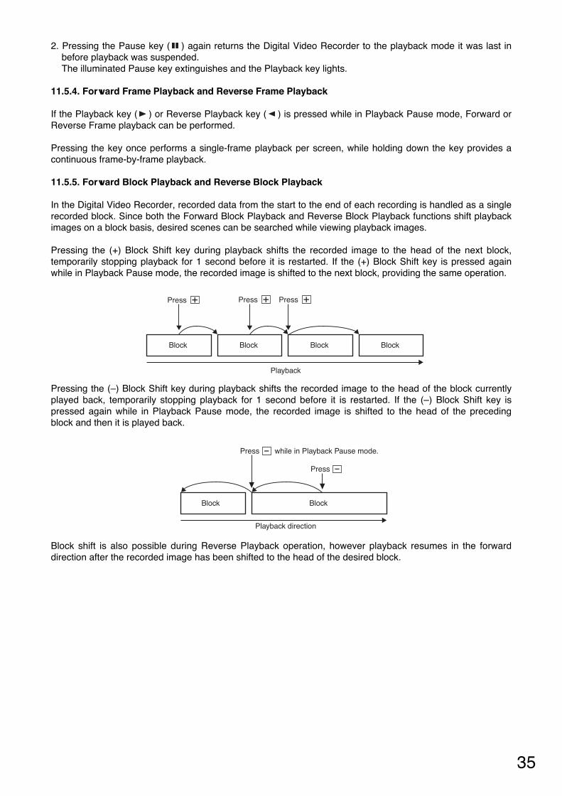
35
Press + Press + Press +
Block Block Block Block
Playback
Block Block
Playback direction
Press -
Press - while in Playback Pause mode.
2. Pressing the Pause key ( ) again returns the Digital Video Recorder to the playback mode it was last inbefore playback was suspended. The illuminated Pause key extinguishes and the Playback key lights.
11.5.4. Forward Frame Playback and Reverse Frame Playback
If the Playback key ( ) or Reverse Playback key ( ) is pressed while in Playback Pause mode, Forward orReverse Frame playback can be performed.
Pressing the key once performs a single-frame playback per screen, while holding down the key provides acontinuous frame-by-frame playback.
11.5.5. Forward Block Playback and Reverse Block Playback
In the Digital Video Recorder, recorded data from the start to the end of each recording is handled as a singlerecorded block. Since both the Forward Block Playback and Reverse Block Playback functions shift playbackimages on a block basis, desired scenes can be searched while viewing playback images.
Pressing the (+) Block Shift key during playback shifts the recorded image to the head of the next block,temporarily stopping playback for 1 second before it is restarted. If the (+) Block Shift key is pressed againwhile in Playback Pause mode, the recorded image is shifted to the next block, providing the same operation.
Pressing the (–) Block Shift key during playback shifts the recorded image to the head of the block currentlyplayed back, temporarily stopping playback for 1 second before it is restarted. If the (–) Block Shift key ispressed again while in Playback Pause mode, the recorded image is shifted to the head of the precedingblock and then it is played back.
Block shift is also possible during Reverse Playback operation, however playback resumes in the forwarddirection after the recorded image has been shifted to the head of the desired block.

36
11.6. About the Playback Start Position
• If playback is initiated from the camera display screen, the playback begins from the position at which it waslast stopped. When the power is switched on or when the position previously played back has beenoverwritten, playback is started from the oldest recorded image. During recording, playback is started fromthe most recent data in the currently recorded block.
• Pressing the Playback key ( ) (or the Reverse Playback key ( )) while holding down the Playback Stopkey ( ) while in Stop or Playback mode shifts the recorded image to the following position for playback.
Current position
Oldest block
Playback direction
Most recent block
Press + Press +
Block Block
Playback direction
Current position (recording is in progress)
(playback from the most recent data)
Press + Press +
• Pressing the Playback key ( ) (or the Reverse Playback key ( )) while holding down the Playback Stopkey ( ) during recording causes playback to be started from the following position.
NoteWhen playing back in the forward direction, if the Pre-alarm time has been set to 10 second or more and theDigital Video Recorder is in alarm standby mode, playback is started from 10 minutes before the most recentblock is played back.

37
Note• When no recording exists at the designated time, the first image of
the recorded block following the designated time is displayed. • Attempting to perform searches beyond the current time results in a
display of the "INVALID SEARCH" indication on the Date/TimeSearch screen.
12. SEARCH FUNCTIONS
The following three methods are available to search recorded data (images):1. Date/Time Search : Playback can be initiated by designating the date and time. 2. Block Search : Playback can be initiated by selecting the recorded block. 3. Time Shift Search : Playback can be initiated by increasing or decreasing times from the designated time.The Digital Video Recorder handles recorded data from the start to the end of each recording as a singlerecorded block.
The above three search methods differ in operation.
DATE / TIME SEARCH
JAN / 01 / 04 00 : 00
12.2. Date/Time and Block Searches
12.2.1. Basic Date/Time Search and Block Search Operations
1. Press the Search key. The Search menu screen is displayed. Playback stops if the key is pressed during playback. Pressing the Search key again returns the display to the cameraimage screen.
2. Move the cursor to select the desired search function with the ( ) or( ) key, then confirm the selection with the Select key.
Setting Value ContentsSetting Items
DATE/ TIME SEARCH
BLOCK SEARCH
Recorded images are searched by directly entering the date and time
Recorded images are searched by selecting the recorded block.
Date/ time data entry
–
SEARCH
• DATE / TIME SEARCHBLOCK SEARCH
12.2.2. Date/Time Search Operation
• Move the cursor with the ( ) or ( ) key, and change setting valueswith the (–) or (+) key.
• Executing searches with the Select key displays the image of thedesignated time on the still picture mode screen. The Pause keylights green.
• Playback begins if the Pause key ( ) is pressed.
DIGITAL VIDEO RECORDER
DISK FULL/ FAILURE
ALARMRESET
BUZZER STOP
SEARCHMENUSELECT
BLOCK
PLAYSTOPPLAYPAUSE
REVERSEPLAYRECTIMER
FRAME FRAME
OUTPUT
VIDEO AUDIO
Pause key
Playback key
Playback Stop key
Select key Search key
Block Shift key
Up Shift key
Down Shift key
12.1. The Keys to Be Used in Searching
The following keys are used in search operation:

38
BLOCK SEARCH
N JAN / 01 / 04 21 : 35 : 27 AMJAN / 01 / 04 21 : 35 : 27 – – – – – / – – / –– –– : –– : –– – – – – – / – – / –– –– : –– : –– – – – – – / – – / –– –– : –– : –– – – – – – / – – / –– –– : –– : –– – – – – – / – – / –– –– : –– : –– – – – – – / – – / –– –– : –– : –– – – – – – / – – / –– –– : –– : –– – – – – – / – – / –– –– : –– : –– – – – – – / – – / –– –– : –– : –– – – – – – / – – / –– –– : –– : –– – – – – – / – – / –– –– : –– : –– – – – – – / – – / –– –– : –– : ––
[Recorded block types]Recorded block types are classified by characters "N," "T," and "A."
1
ContentsItem
N
T
A
General Recording block
Internal Timer Recording block
Alarm Recording block
[Recorded block attribute]Character M represents data attribute types.
2
[Hard disk types]Characters A and B represent built-in hard disk drives.
3
ContentsItem
A
B
Data contained in Hard Disk A
Data contained in Hard Disk B
12.2.3. Block Search Operation
• Using the ( ) or ( ) key, move the cursor to scroll the screen andselect the desired block. The ( ) indication is displayed when data exists before the currentlydisplayed search screen, while the ( ) indication is displayed whendata exists after the currently-displayed search screen.
Block Block Block
“Loop” playback“Loop” playback“Loop” playback
Press +Press -Head of the selected block
• Executing searches with the Select key displays the first image of the block on the still picture screen. Theimage is played back if the Pause key is pressed. Pressing the (+) or (–) key while in the Pause modedisplays the first image of the block, performing playback from one block to another. After the block hasswitched over to another block, playback can be performed even without pressing the Pause key.
• "Loop" playback is performed for all playback operations after Block Shift search.
Note• "Loop" playback: Repeats playback of each recorded block.• Pressing the Playback Stop key ( ) and the Playback key ( ) again during "Loop" playback resets the
"Loop" playback, causing playback to be performed on a time basis.
1 2 3
NoteThe Alarm Recording block time represents the time that an alarm was received. If the Pre-alarm function hasbeen set, Alarm Recording begins from the image recorded before the indicated alarm time.
NoteAvoid mixing both Normal Recordings and Mirroring Recordings on the hard disk. If mixed, block shift orsearch operations cannot be correctly performed during playback. (Refer to p. 15; "Disk Settings.")
ContentsItem
No Indication
M
Normal Recordung data
Mirroring Recording data

39
Note• Continuous or normal forward/reverse frame playback can also be performed even when the Time Shift
Search screen is displayed (even while the Pause key is flashing).• If Time Shift Search operation exceeds the range of "Loop" playback during "Loop" playback, the "Loop"
playback is reset, reverting to normal playback.
12.3. Time Shift Search
1. Press the Pause key on the playback screen to suspend playback.
2. Press the Search key.The Time Shift Search screen is displayed, and the Pause keyflashes.Pressing the Search key again returns the display to theplayback pause screen.
3. Using the ( ) or ( ) key, change the time period to be shifted.Theshift time period increases as the ( ) key is pressed, and decreasesas the ( ) key is pressed. It can be set to a variable period of 1 – 60minutes.
4. Press the (+) or (–) key.The (+) key advances the shift time period by the designated length of time, while the (–) key reverses thetime period by the same designated length of time. If no image exists at the designated time, pressing the(+) key displays the image following the designated time, while the image preceding the designated time isdisplayed if the (–) key is pressed.
5. Press the Search key to reset the Time Shift Search.The display is temporarily stopped at the searched Time Shift screen.
6. Press the Pause key to begin playback of the searched image.
THU JAN / 01 / 0400 : 00 : 00
SHIFT TIME CHANGE : / SHIFTING : – / +CANCEL : SEARCH
SHIFT: 10MINLEVEL3 1 /60 A
Pause
“Loop” playback
Time Shift Time Shift
Block BlockBlock
Block Block Block
PauseTime Shift Time Shift
Playback operation on a time basis
When the Time Shift Search function is operated within the "Loop" playback range:
When the Time Shift Search function is operated beyond the "Loop" playback range:

40
13. CONNECTIONS
13.1. Preparations for Connections
Switch off the power to the Digital Video Recorder and all connected equipment before performingconnections. The Digital Video Recorder has built-in hard disks. To avoid damage to them, when moving theDigital Video Recorder, be sure to leave the Recorder’s Main Power switch turned off for at least 30 secondsbefore moving.
13.1.1. Control Input/Output Terminal Connections
Applicable cables are as follows:• Solid cable : AWG28 (ø 0.32mm) – AWG22(ø 0.65mm)• Twisted cable: AWG28 (0.08mm2) – AWG22(0.32mm2)To connect, remove the cable sheath 10 mm from the cable end, and then insert the cable into the terminalpressing on the tab on the terminal using a screwdriver.
13.2. When Using the 24V AC or 12V DC or AC Mains Camera:
Connect the Digital Video Recorder’s Video Input terminal to the camera’s video output terminal.
13.3. Connections to the Monitor TV
The Digital Video Recorder’s terminals to be connected to the monitor differ depending on the type ofconnected equipment.
• When the Digital Video Recorder is not connected to the Multi-switcher:Connect the Recorder’s Video Output terminal to the monitor’s video input terminal, and the Recorder’sAudio Output terminal to the monitor’s audio input terminal.
• When the Digital Video Recorder is connected to the Multi-switcher:Connect the Recorder’s Switcher Video Output terminal to the monitor’s video input terminal, and theRecorder’s Audio Output terminal to the monitor’s audio input terminal.

41
13.4. Combination With The Digital Video Recorder/ Multi-switchers (C-MS91D and C-MS161D)
The Digital Video Recorder has been designed with an emphasis on the synchronization with the TOA Multi-switchers (C-MS91D, C-MS161D).By synchronizing the Digital Video Recorder with the Multi-switcher, the following advantages – unavailable toconventional systems using analog time-lapse VCRs – can be realized. 1. The Multi-switcher does not need to be operated when operating the Digital Video Recorder. 2. The Digital Video Recorder’s main menu screen or search screen can be easily displayed, facilitating
settings and search operations. The combined Digital Video Recorder/Multi-switcher system is called a basic system in this manual. Since the Multi-switcher has 2 VCR output terminals, hard disk space can be doubled by connecting twoDigital Video Recorders. This system is called an expansion system. The expansion system does not permitthe synchronization between the Digital Video Recorder and the Multi-switcher.
13.4.1. Basic System
Perform connections as shown in connection examples. (Refer to p. 43)Set the Multi-switcher (C-MS91D and C-MS161D) and the Digital Video Recorder as follows:
13.4.2. Expansion System (Series Recording)
Perform connections as shown in connection examples. (Refer to p. 44)The Digital Video Recorder settings are as follows:
• OperationIf the first Digital Video Recorder’s hard disk space becomes full, a signal is provided from the Disk Full Outputterminal. When the signal is received at the second Digital Video Recorder’s Recording Start Input terminal, itsDisk Full mode is reset, allowing recording to be started in the second unit. Note• Recording operation and Internal Timer Recording cannot be performed at the front panel of the Digital
Video Recorder set to Disk Full mode. • Multi-switcher can be synchronized from the unit set to master through the RS-232C interface.Set
Communication Setting’s Switcher Synchronization to “TIME SYNC.”
• Multi-switcher settingsPerform remote and recording settings as follows:
• Digital Video Recorder settingsPerform communication settings as follows:
ContentsSetting Items
Remote
Settings
RS-232C
RS-232C
38.4kbps (Default)
1 (Default)
2
OFF*1
Recording Pattern
Operation
Motion Detection
Pattern Operation
RS-232C
RS-232C Protocol
Recording Device
Date/Time (VCR)
ContentsSetting Items
Communication
Settings
38400bps (Default)
OFF (Default)
ON
RS-232C
Transmission Rate
RS-232C Flow Control
Switcher
Synchronization*2
Recording Pattern
Motion Detection
Pattern
Recording
Settings
Buzzer/
Character
Display Settings
When perform-
ing Internal
Timer Recording
settings
Match the Recorder’s
settings to those of the
Multi-switcher
Note*1 Use the Digital Video Recorder’s date/time display function for date/time display. If set at both the Multi-
switcher and Digital Video Recorder, characters overlap and cannot be seen clearly.*2 Recording Pattern, Motion Detection Pattern, Camera/ VCR mode selection, and Time Synchronization
switcher functions can all be controlled by the Digital Video Recorder. However, when syncronizing theswitcher's clock from the Recorder, set the Recorder's clock Time Synchronization setting to "MASTER."Time synhronization cannot be performed if set to "SLAVE."When only performing time synchronization, set the communication swither synchronization setting to"TIME SYNC." Please note that in this mode Recording Pattern,Motion Detection Pattern, and Camera/VCR mode selection functions cannot be controlled.
• For more information on the Multi-switcher’s settings, refer to the instruction manual for the Multi-switcher.
First Digital Video RecorderSetting Items
Recording Mode
Time Synchronization
Disk Full indicator status
SERIES
MASTER
OFF
Second Digital Video Recorder
SERIES
SLAVE
ON

42
VID
EO
OU
T
GN
D
Sensor etc.
Vid
eo In
put
Vid
eo O
utpu
t
Video Input
1CH Digital Video Recorder
Monitor TV
Camera
AC MAINS MAIN POWER
ON
OFF
IN OUT IN OUT
VIDEO SW VIDEO IN
OUT
AUDIO GND GND100BASE–TX
ALARM RESET OUTALARM INSW CTRL OUT
TIME SYNC INREC STOP IN
REC START INALARM RESET IN
TIME SYNC OUTALARM OUT
FAILURE OUTDISK FULL OUT
RS–232C
GND
ALARM RESET OUTALARM INSW CTRL OUT
14. CONNECTION EXAMPLES
14.1. Connection to the 24V AC or 12V DC or AC Mains Camera.
NotePower Sync cameras cannot be used.

43
VTR1
1
9
D-Sub9 Pin
GN
D
RS
-232
CR
S-2
32C
1CH Digital Video Recorder
AC MAINS MAIN POWER
ON
OFF
IN OUT IN OUT
VIDEO SW VIDEO IN
OUT
AUDIO GND GND100BASE–TX
ALARM RESET OUTALARM INSW CTRL OUT
TIME SYNC INREC STOP IN
REC START INALARM RESET IN
TIME SYNC OUTALARM OUT
FAILURE OUTDISK FULL OUT
RS–232C
Monitor TV
Vid
eo In
put
Vid
eo O
utpu
t
Video Input
GND
ALARM RESET OUTALARM INSW CTRL OUT
Video Input 1 – 9
Sensor etc.
Multi-switcher (C-MS91D)
Ala
rm O
utpu
t
Alarm Input/Output
Mon
itor
Out
put1
VC
R O
utpu
t1
VC
R In
put1
Sw
itche
r C
ontr
ol In
put
Sw
itche
rV
ideo
Out
put
Sw
itche
rVid
eo In
put
Camera
Camera
14.2. Connection to the Multi-switcher
14.2.1. Basic System (Combined with the C-MS91D Multi-switcher)
NotePower Sync cameras cannot be used.

44
VTR1 VTR2
AC MAINS MAIN POWER
ON
OFF
IN OUT IN OUT
VIDEO SW VIDEO IN
OUT
AUDIO GND GND100BASE–TX
ALARM RESET OUTALARM INSW CTRL OUT
TIME SYNC INREC STOP IN
REC START INALARM RESET IN
TIME SYNC OUTALARM OUT
FAILURE OUTDISK FULL OUT
RS–232C
AC MAINS MAIN POWER
ON
OFF
IN OUT IN OUT
VIDEO SW VIDEO IN
OUT
AUDIO GND GND100BASE–TX
ALARM RESET OUTALARM INSW CTRL OUT
TIME SYNC INREC STOP IN
REC START INALARM RESET IN
TIME SYNC OUTALARM OUT
FAILURE OUTDISK FULL OUT
RS–232C
GN
D
GN
D
GN
DGND
VC
R In
put 1
VC
R In
put 2
Mon
itor
Out
put 1
VC
R O
utpu
t 1
VC
R O
utpu
t 2 Alarm Output
Sw
itche
r C
ontr
ol In
put
Ala
rm O
utpu
t
Sw
itche
r C
ontr
ol In
put
Sw
itche
r C
ontr
ol
Out
put
Sw
itche
rVid
eoIn
put
Vid
eo In
put
Vid
eo O
utpu
t
Sw
itche
rV
ideo
Out
put
Sw
itche
rVid
eoIn
put
Vid
eo In
put
Vid
eo O
utpu
t
Switcher Video Output
Ala
rm In
put
Ala
rm In
put
Switcher Control Output
Rec
ordi
ng S
tart
Inpu
t
Rec
ordi
ng S
tart
Inpu
t
Dis
kful
l Out
put
Dis
kful
l Out
put
GN
D
GN
D
Monitor TV
Vid
eo In
put
Sensor etc.
Multi-switcher (C-MS91D)
1CH Digital Video Recorder (1)
1CH Digital Video Recorder (2)
1
9
Video Input 1 – 9
Camera
Camera
Tim
e S
ync
Inpu
t
Tim
e S
ync
Out
put
Slave
Master
14.2.2. Expansion System (Combined with the C-MS91D Multi-switcher)
NotePower Sync cameras cannot be used.

45
15.2. When using the C-DR0100
Disk Mode : NORMAL Audio Record : ON
1/60813172232
1/301726334362
1/1533526484 120
1/10507895124 176
1/597150183234 325
1/3158239289364 494
1/2227337402498 654
1409580674804 996
2681901101111501334
3878111212201352 1516
51134135614501558 1684
101460163116971769 1848
201704181518551898 1942
3018031884191319431973
6019161961197619922008
Level 1Level 2Level 3Lebel 4Level 5
Picturequality
64KB40KB32KB24KB16KB
File Size
Recording Time Intervals (Sec), Recording Time Period
Disk Mode : NORMAL Audio Record : OFF
1/60914172233
1/301727344465
1/1534546789 131
1/105181101133196
1/5103163202267 392
1/3171271337445 654
1/2257407505667 981
151381310111334 1962
21026162720212668 3924
31539244030324002 5885
52565406750536670 9809
10513181341010613340 19618
2010262162682021226680 39236
3015392244033031840020 58853
6030785488056063780041 117707
Level 1Level 2Level 3Lebel 4Level 5
Picturequality
64KB40KB32KB24KB16KB
File Size
Recording Time Intervals (Sec), Recording Time Period
15. RECORDING TIME TABLE
15.1. Recording Picture Quality Setting
The Digital Video Recorder is designed to be used as a hard disk recorder for surveillance applications, andits picture quality can be set to Levels 1 – 5. Whether emphasis is placed on picture quality or on recordinginterval can be selected depending on surveillance conditions. When setting the picture quality, carefullyconsider recording times, recording intervals, recording types and other surveillance conditions, and be sureto carry out test recordings in advance to ensure that the required picture quality is maintained.
Note: Recording time is given as a guideline reference.
Disk Mode : NORMAL Audio Record : ON
1/601727334464
1/3034536586124
1/1567105129168 240
1/10100155191247 351
1/5195300365468 651
1/3315478577729 988
1/2454674804996 1308
1818116013471607 1991
21361180320212300 2668
31755222324402704 3032
52269271129003117 3369
102919326233943538 3695
203407363037113795 3884
3036053768382638853947
6038323922395339844016
Level 1Level 2Level 3Lebel 4Level 5
Picturequality
64KB40KB32KB24KB16KB
File Size
Recording Time Intervals (Sec), Recording Time Period
Disk Mode : NORMAL Audio Record : OFF
1/601727344465
1/3034546789131
1/1568108135178 262
1/10103163202267 392
1/5205325404534 785
1/3342542674889 1308
1/251381310111334 1962
11026162720212668 3924
22052325440425336 7847
33078488160648004 11771
5513181341010613340 19618
101026216268 20212 26680 39236
202052332537 40425 53360 78471
303078548805 60637 80041 117707
606157097610 121274 160081 235413
Level 1Level 2Level 3Lebel 4Level 5
Picturequality
64KB40KB32KB24KB16KB
File Size
Recording Time Intervals (Sec), Recording Time Period
15.3. When using the C-DR0101

46
Disk Mode : MIRRORING Audio Record : ON
1/60–––––
1/301726334362
1/1533526484 120
1/10507895124 176
1/597150183234 325
1/3158239289364 494
1/2227337402498 654
1409580674804 996
2681901101111501334
3878111212201352 1516
51134135614501558 1684
101460163116971769 1848
201704181518551898 1942
3018031884191319431973
6019161961197619922008
Level 1Level 2Level 3Lebel 4Level 5
Picturequality
64KB40KB32KB24KB16KB
File Size
Recording Time Intervals (Sec), Recording Time Period
Disk Mode : MIRRORING Audio Record : OFF
1/60–––––
1/301727344465
1/1534546789 131
1/105181101133196
1/5103163202267 392
1/3171271337445 654
1/2257407505667 981
151381310111334 1962
21026162720212668 3924
31539244030324002 5885
52565406750536670 9809
10513181341010613340 19618
2010262162682021226680 39236
3015392244033031840020 58853
6030785488056063780041 117707
Level 1Level 2Level 3Lebel 4Level 5
Picturequality
64KB40KB32KB24KB16KB
File Size
Recording Time Intervals (Sec), Recording Time Period
NoteSetting the Disk Setting’s Disk Mode to "MIRRORING" limits the maximum recording interval to 1/30 second.(Refer to p. 15;"Disk Setting.")
15.4. When using the C-DR0105
Disk Mode : NORMAL Audio Record : ON
1/6034546789129
1/3068108133174252
1/15136213263342 490
1/10203316389504 716
1/5397612746955 1328
1/3643976117914882017
1/29261375164020322670
116702368275132814064
22779368041264695 5447
33583453949825520 6189
54631553559206363 6877
105959665869307224 7544
206956741075757748 7928
3073607693781179328057
6078228006806981338199
Level 1Level 2Level 3Lebel 4Level 5
Picturequality
64KB40KB32KB24KB16KB
File Size
Recording Time Intervals (Sec), Recording Time Period
Disk Mode : NORMAL Audio Record : OFF
1/6034556890133
1/3069110137181267
1/15139221275363 534
1/10209332412544 801
1/54196648251089 1602
1/36981107137518152670
1/21047166020632723 4005
12095332141265447 8010
24190664282531089416020
362859964123791634124031
510475166062063227235 40051
102095033213 41265 55470 80103
204190066427 82531 108941160207
306285099641 123796163411240311
60125701199282247593 326823 480622
Level 1Level 2Level 3Lebel 4Level 5
Picturequality
64KB40KB32KB24KB16KB
File Size
Recording Time Intervals (Sec), Recording Time Period
Disk Mode : MIRRORING Audio Record : ON
1/60–––––
1/3034546687126
1/1568106131171245
1/10101158194252 358
1/5198306373477 664
1/3321488589744 1008
1/24636878201016 1335
18351184137516402032
213891840206323472723
31791226924912760 3094
52315276729603181 3438
102979332934653612 3772
203478370537873874 3964
3036803846390539664028
6039114003403440664099
Level 1Level 2Level 3Lebel 4Level 5
Picturequality
64KB40KB32KB24KB16KB
File Size
Recording Time Intervals (Sec), Recording Time Period
Disk Mode : MIRRORING Audio Record : OFF
1/60–––––
1/3034556890133
1/1569110137181267
1/10104166206272400
1/5209332412544 801
1/3349553687907 1335
1/2523830103113612002
11047166020632723 4005
22095332141265447 8010
33142498261898170 12015
552378303103161361720025
1010475166062063227235 40051
2020950332134126554470 80103
3031425498206189881705 120155
606285099641123796163411240311
Level 1Level 2Level 3Lebel 4Level 5
Picturequality
64KB40KB32KB24KB16KB
File Size
Recording Time Intervals (Sec), Recording Time Period

47
16. EXTERNAL TERMINAL SPECIFICATIONS
16.1. RS-232C Communication Specifications
The Digital Video Recorder’s RS-232C interface permits remote control using a connected PC.
Note• Control software is not supplied as standard.• Communication specifications are those set when the Switcher Synchronization selection on the
Communication Setting Screen is set to "OFF."• TOA takes no responsibility for any inconvenience or damage to customer hardware or software which may
result from the use of control software based on the specifications described in this section.
16.1.1. The Rules of Overall Communications
1. All communications are established by means of a command from the controller. 2. Responses are always present in mutual communications. 3. The response timeout period is 1 second, and the timeout period between continuous data is 100
milliseconds. When the timeout occurs, the corresponding communications are regarded as failed.4. Data is only updated when a communication setting content update command is received while in Standby
mode or in Idle and Recording Pause mode. No setting content update commands are accepted duringsystem activation, error message indication, menu screen display, search screen display, playback,recording (Include Alarm Recording Setting’s Alarm is set to “VALID.”) or while in timer mode (DEL isreturned).
5. When command operation cannot be performed, received data is discarded and any commands areregarded as invalid.
16.1.2. Communication Protocol
Transfer System : Start/stop system (asynchronous system), duplexParity Bit : EvenTransfer Rate : 9,600, 19,200, 38,400 bpsCode : Binary codeBit Length : 8 bitsFlow Control : CTS/RTS handshaking, noneStop Bit : 1Error Control : None
16.1.3. RS-232C Connector Pin Arrangement
The following table shows the signal name of each pin of the RS-232C D-sub 9P connector.
Signal NamePin No.
Unconnected
RXD (Received Data)
TXD (Transmitted Data)
Unconnected
GND
Unconnected
RTS (Request to send)
CTS (Clear to send)
Unconnected
1
2
3
4
5
6
7
8
9
Note: The plug for the RS-232C connector is not supplied with the Digital Video Recorder. Use a cross cable for the RS-232C interface connection.

48
STX LEN COMMAND PARA DATA ETXItem
1 1 2 2 Variable 1No. of Byte
STX : Fixed to A0H.LEN : The number of bytes from command to DATACOMMAND : BT, MS, MV, LG, SE*1
PARA : Parameter*1
DATA : DATA section (variable depending on a command and parameter)ETX : Fixed to AFH.
*1 If communication data is transmitted, an ACK, NAK, or DEL signal is returned immediately after the data isreceived. ACK (06H) : Correct receptionNAK (15H) : Reception errorDEL (7FH) : Invalid operation
16.1.5. RS-232C Communication Command (Controller Digital Recorder)
Commands are 2 bytes in length. Parameters (PARA) are also 2 bytes. They are followed by the multi-byteDATA section. If DATA LEN is "0," no DATA section follows.
Key's CommandsCommand
BTPARA
PLSTRVPSRDDCMNONPOPFSCQTALRSKHUPDWLFRTSL
DATA LEN00000000000000000000
OperationPlayback KeyPlayback Stop KeyReverse Playback KeyPause KeyRecording KeyBuzzer Stop KeyMenu Key (Press Menu Key for 1 second or more)Start Internal Timer Recording (Press Timer key for 1 second or more)Standby Key ONStandby Key OFFSearch KeyPeriodical Status Inquiry (Response returned)Alarm OperationRecording Stop Key (Press Recording Key for 1 second or more)Recording Start OperationUp Shift KeyDown Shift Key– Key+ KeySelect Key
16.1.4. RS-232C Communication Format (Controller Digital Recorder)

49
Operation0 – 4 (Level 5 – Level 1)
0 : OFF, 1 : ON0:1/60, 1:1/30, 2:1/15, 3:1/10, 4:1/5, 5:1/3, 6:1/2, 7:1, 8:2, 9:3, A:5,B:10, C:20, D:30, E:600 – 9 (1,2,3,4,5,10,15,20,30,60)0 – 9: Setting No.01 – 100:Cancel, 1:Daily, 2:WeeklyFirst byte MM:1 – C, Second byte DD:1 – 1FBIT0:Sun, BIT1:Mon, BIT2:Tue, BIT3:Wed, BIT4:Thu, BIT5:Fri,BIT6:SatFirst byte HH:0 – 17, Second byte MM:0 – 3BFirst byte HH:0 – 17, Second byte MM:0 – 3B0 – 4 (Level 5 – Level 1)
0:OFF, 1:ON
0:1/60, 1:1/30, 2:1/15, 3:1/10, 4:1/5, 5:1/3, 6:1/2, 7:1, 8:2, 9:3, A:5,B:10, C:20, D:30, E:600:1, 1:20:1, 1:20: Invalid, 1:Valid, 2:Valid during recording (Val Rec)0:Edge, 1:Level0 – 7 (0Sec, 10Sec, 15Sec, 20Sec, 30Sec, 1Min, 2Min, 5Min)0 – 9 (10Sec, 15Sec, 20Sec, 30Sec, 1Min, 2Min,, 3Min, 4Min, 5Min,10Min)0 – 7 (0Sec, 10Sec, 15Sec, 20Sec, 30Sec, 1Min, 2Min, 5Min)0 – 4 (Level 5 – Level 1)0:OFF, 1:ON0:1/60, 1:1/30, 2:1/15, 3:1/10, 4:1/5, 5:1/3, 6:1/2, 7:10:OFF, 1:ON0:During Alarm Recording, 1:1Second0:Nomal, 1:Mirroring0:Stop, 1:Re-Rec, 2:SeriesYYYY:7D0 – 833 (2000 – 2099 Year)MM: 1 – C (Jan – Dec Month)DD: 1 – 1F (1 – 31 Date)HH: 0 – 17 (00:00 – 23:00 Hour)MM: 0 – 3B (0 – 59 Minute)SS: 0 – 3B (0 – 59 Second)0: Hide, 1:Display 0: Hide, 1:Display 0: Hide, 1:Display 0: Hide, 1:Display 0: Hide, 1:Display Disk Mode set to Nomal : 0:Hide, 1:DisplayDisk Mode set to Mirroring: 0:Hide, 1:Max, 2:Min, 3:HDD-A, 4:HDD-B0: Hide, 1:Display 0: Hide, 1:Display 0:Upper Left, 1: Upper Center, 2:Upper Right, 3: Lower Left, 4: Lower Center, 5: Lower Right0: Hide, 1:Display
0: 9600, 1: 19200, 2: 38400 bps0:OFF, 1:ON0:Master, 1:Slave0 – 230:OFF, 1:ON, 2:Time Sync0:All, 1:HDD-A, 2:HDD-B0:Disallow, 1:Allow0:OFF, 1:ON1 – C:Jan – Dec Month1:Fast, 2:Second, 3:Third, 4:Fourth, 5:Last0 – 17:00 – 23 Hour1 – C:Jan – Dec Month1:Fast, 2:Second, 3:Third, 4:Fourth, 5:Last0 – 17:00 – 23 Hour
CommandMS
PARARQ
RDRI
RCTM
ASANAPAT
AFAQADAIABAOWDWMDT
VQVDVWVRVPVG
VHVTVC
VM
TRTFTSTTTCPMPRSUSMSWSHEMEWEH
DATA LEN1
11
11121
221
1
1
111112
21111111211111111111
111
1
11111111111111
ContentsGeneral Recording Setting PictureQualityGeneral Recording Setting AudioGeneral Recording Setting RecordingIntervalSwitcher Control PeriodSetting Frame No.Timer Setting ModeDateDay of the week
Timer Start TimeTimer End TimeInternal Timer Recording SettingPicture QualityInternal Timer Recording SettingAudioInternal Timer Recording SettingRecording IntervalRecording PatternMotion Detection PatternAlarm SettingAlarm Input ModePre-Alarm PeriodAlarm Recording Period
Post-Alarm PeriodAlarm Recording Picture QualityAlarm Recording AudioAlarm Recording Recording IntervalBuzzer Sound OutputAlarm Output PeriodDisk Mode (C-DR0101, C-DR0105)Recording ModeDate/Time Setting YearDate/Time Setting MonthDate/Time Setting DateDate/Time Setting HourDate/Time Setting MinuteDate/Time Setting SecPicture Quality DisplayAudio ON/OFF DisplayRe-Recording ModeRecording Mode DisplayPlayback DisplayRemaining Time Display
Date DisplayTime DisplayDate/Time Display Position
Disk Mode Indication (C-DR0101, C-DR0105)Communication RateFlow ControlTime SynchronizationSynchronized TimeSwitcher SynchronizationPlayback ModeSimultaneous Recording/PlaybackSummer Time SettingSummer Time First day MonthSummer Time First day SundaySummer Time First day TimeSummer Time Last day MonthSummer Time Last day SundaySummer Time Last day Time
Menu Setting Commands

50
Note: Date/Time search is performed using setting data.
OperationRequest to send setting contents
Request to send setting contentsRequest to send setting contents
Request to send setting contents0 – 9: Setting No., Request to send setting contentsRequest to send setting contentsRequest to send setting contentsRequest to send setting contentsRequest to send setting contentsRequest to send setting contentsRequest to send setting contentsRequest to send setting contentsRequest to send setting contentsRequest to send setting contentsRequest to send setting contentsRequest to send setting contentsRequest to send setting contentsRequest to send setting contents (current time)Request to send setting contentsRequest to send setting contentsRequest to send setting contentsRequest to send setting contentsRequest to send setting contentsRequest to send setting contentsRequest to send setting contentsRequest to send setting contentsRequest to send setting contentsRequest to send setting contentsRequest to send setting contentsRequest to send setting contentsRequest to send setting contentsRequest to send setting contentsRequest to send setting contentsRequest to send setting contentsRequest to send setting contentsRequest to send setting contentsRequest to send setting contentsRequest to send setting contentsRequest to send setting contentsRequest to send setting contentsRequest to send setting contentsRequest to send setting contents
CommandMV
PARARQ
RDRI
RCTMASANAPATAFAQADAIABAOWDWMDTVQVDVWVRVPVGVHVTVCVMTRTFTSTTTCPMPRSUSMSWSHEMEWEH
DATA LEN0
00
010000000000000000000000000000000000000
ContentsGeneral Recording Setting Picture QualityGeneral Recording Setting AudioGeneral Recoding Setting Recording IntervalSwitcher Control PeriodTimer Setting DataAlarm SettingAlarm Input ModePre-Alarm PeriodAlarm Recording PeriodPost-Alarm PeriodAlarm Recording Picture QualityAlarm Recording AudioAlarm Recording Recording IntervalBuzzer Sound OutputAlarm Output PeriodDisk Mode (C-DR0101, C-DR0105)Recording ModeClock Setting DataPicture Quality DisplayAudio DisplayRecording Mode DisplayRecording DisplayPlayback DisplayRemaining Time DisplayDaily DisplayTime DisplayDate/Time Display PositionDisk Mode Indication (C-DR0101,C-DR0105)Transmission RateFlow ControlTime SynchronizationSynchronized TimeSwitcher SynchronizationPlayback ModePlayback during RecordingSummer Time SettingSummer Time First day MonthSummer Time First day SundaySummer Time First day TimeSummer Time Last day MonthSummer Time Last day SundaySummer Time Last day Time
Menu Setting Content Request Command
OperationRequest for sending from the head of the most recent dataRequest for continued dataRequest for sending from the head of the most recent dataRequest for continued dataRequest for sending from the head of the most recent dataRequest for continued data
CommandLG
PARARDRQALAQTRTQ
DATA LEN000000
ContentsRequest for Recording LogNext Request for Recording LogRequest for Alarm Recording LogNext Request for Alarm Recording LogRequest for Failure LogsNext Request for Failure Logs
Log Request Command
OperationYYYY: 7D0 – 833 (2000 – 2099 Year)MM: 1 – C (Jan – Dec Month)DD: 1 – 1F (1 – 31 Date)HH: 0 – 17 (00:00 – 23:00 Hour)MM: 0 – 3B (0 – 59 Minute)
CommandSE
PARASD
DATA LEN21111
ContentsDate/Time Search YearDate/Time Search MonthDate/Time Search DateDate/Time Search HourDate/Time Search Minute
Search Menu Execution Command

51
CommandBT
16.1.7. RS-232C Communication Command (Digital Recorder Controller)
Commands are 2 bytes in length. Parameters (PARA) are also 2 bytes. They are followed by the multi-byteDATA section.
Key response command
Operation0:Power OFF, 1:Power ON0:Standby or Stop1:Pause2:Playback3:Fast Forward Playback4 Reverse Playback5:Rewind6.Menu or Search Screen Display7:Disk Error or disk operation such as disk recognition0:Standby or Stop1:Recording2:Alarm Recording3:Internal Timer Recording0: No failure1: Hard disk failure2: Video loss failure3: Fan failure
PARAQT
DATA LEN11
1
1
ContentsOperation StatusStatus
Recording Status
Failure
16.1.6. RS-232C Communication Format (Digital Recorder Controller)
STX : Fixed to A0H.LEN : The number of bytes from command to DATACOMMAND : BT, MV, LGPARA : ParameterDATA : DATA section (variable depending on a command and parameter)ETX : Fixed to AFH.
STX LEN COMMAND PARA DATA ETXItem
1 1 2 2 Variable 1No. of Byte

52
Menu Setting Content Response Command
Operation0 – 4 (Level 5 – Level 1)
0 : OFF, 1 : ON0:1/60, 1:1/30, 2:1/15, 3:1/10, 4:1/5, 5:1/3, 6:1/2, 7:1, 8:2, 9:3, A:5,B:10, C:20, D:30, E:600 – 9 (1,2,3,4,5,10,15,20,30,60)0 – 9: Setting No.01 – 100:Cancel, 1:Daily, 2:WeeklyFirst byte MM:1 – C, Second byte DD:1 – 1FBIT0:Sun, BIT1:Mon, BIT2:Tue, BIT3:Wed, BIT4:Thu, BIT5:Fri,BIT6:SatFirst byte HH:0 – 17, Second byte MM:0 – 3BFirst byte HH:0 – 17, Second byte MM:0 – 3B0 – 4 (Level 5 – Level 1)
0:OFF, 1:ON
0:1/60, 1:1/30, 2:1/15, 3:1/10, 4:1/5, 5:1/3, 6:1/2, 7:1, 8:2, 9:3, A:5,B:10, C:20, D:30, E:600:1, 1:20:1, 1:20: Invalid, 1:Valid, 2:Valid during recording (Val Rec)0:Edge, 1:Level0 – 7 (0Sec, 10Sec, 15Sec, 20Sec, 30Sec, 1Min, 2Min, 5Min)0 – 9 (10Sec, 15Sec, 20Sec, 30Sec, 1Min, 2Min,, 3Min, 4Min, 5Min,10Min)0 – 7 (0Sec, 10Sec, 15Sec, 20Sec, 30Sec, 1Min, 2Min, 5Min)0 – 4 (Level 5 – Level 1)0:OFF, 1:ON0:1/60, 1:1/30, 2:1/15, 3:1/10, 4:1/5, 5:1/3, 6:1/2, 7:10:OFF, 1:ON0:During Alarm Recording, 1:1Second0:Nomal, 1:Mirroring0:Stop, 1:Re-Rec, 2:SeriesYYYY:7D0 – 833 (2000 – 2099 Year)MM: 1 – C (Jan – Dec Month)DD: 1 – 1F (1 – 31 Date)HH: 0 – 17 (00:00 – 23:00 Hour)MM: 0 – 3B (0 – 59 Minute)SS: 0 – 3B (0 – 59 Second)0: Hide, 1:Display 0: Hide, 1:Display 0: Hide, 1:Display 0: Hide, 1:Display 0: Hide, 1:Display Disk Mode set to Nomal : 0:Hide, 1:DisplayDisk Mode set to Mirroring: 0:Hide, 1:Max, 2:Min, 3:HDD-A, 4:HDD-B0: Hide, 1:Display 0: Hide, 1:Display 0:Upper Left, 1: Upper Center, 2:Upper Right, 3: Lower Left, 4: Lower Center, 5: Lower Right0: Hide, 1:Display
0: 9600, 1: 19200, 2: 38400 bps0:OFF, 1:ON0:Master, 1:Slave0 – 230:OFF, 1:ON, 2:Time Sync0:All, 1:HDD-A, 2:HDD-B0:Disallow, 1:Allow0:OFF, 1:ON1 – C:Jan – Dec Month1:Fast, 2:Second, 3:Third, 4:Fourth, 5:Last0 – 17:00 – 23 Hour1 – C:Jan – Dec Month1:Fast, 2:Second, 3:Third, 4:Fourth, 5:Last0 – 17:00 – 23 Hour
CommandMV
PARARQ
RDRI
RCTM
ASANAPAT
AFAQADAIABAOWDWMDT
VQVDVWVRVPVG
VHVTVC
VM
TRTFTSTTTCPMPRSUSMSWSHEMEWEH
DATA LEN1
11
11121
221
1
1
111112
21111111211111111111
111
1
11111111111111
ContentsGeneral Recording Setting PictureQualityGeneral Recording Setting AudioGeneral Recording Setting RecordingIntervalSwitcher Control PeriodSetting Frame No.Timer Setting ModeDateDay of the week
Timer Start TimeTimer End TimeInternal Timer Recording SettingPicture QualityInternal Timer Recording SettingAudioInternal Timer Recording SettingRecording IntervalRecording PatternMotion Detection PatternAlarm SettingAlarm Input ModePre-Alarm PeriodAlarm Recording Period
Post-Alarm PeriodAlarm Recording Picture QualityAlarm Recording AudioAlarm Recording Recording IntervalBuzzer Sound OutputAlarm Output PeriodDisk Mode (C-DR0101, C-DR0105)Recording ModeDate/Time Setting YearDate/Time Setting MonthDate/Time Setting DateDate/Time Setting HourDate/Time Setting MinuteDate/Time Setting SecPicture Quality DisplayAudio ON/OFF DisplayRe-Recording ModeRecording Mode DisplayPlayback DisplayRemaining Time Display
Date DisplayTime DisplayDate/Time Display Position
Disk Mode Indication (C-DR0101, C-DR0105)Communication RateFlow ControlTime SynchronizationSynchronized TimeSwitcher SynchronizationPlayback ModeSimultaneous Recording/PlaybackSummer Time SettingSummer Time First day MonthSummer Time First day SundaySummer Time First day TimeSummer Time Last day MonthSummer Time Last day SundaySummer Time Last day Time

53
Unit HostRequest for recording log
Transmission of recording log (DATA follows)Request for next recording log
Transmission of next recording log (DATA follows)Request for next recording log
Transmission of next recording log (No DATA follows)
ContentsData valid/invalidYearMonthDateTimeMinuteSecondDetailed Code
Continuation sign
Log Content Response Command
Shown below are log information DATA section (13 bytes) formats.
DATA LEN12111114
1
Description of Data0: Invalid, 1: ValidYYYY: 7D0 – 833 (2000 – 2099 Year)MM: 1 – C (Jan – Dec Month)DD: 1 – 1F (1 – 31 Date)HH: 0 – 17 (00:00 – 23:00 Hour)MM: 0 – 3B (0 – 59 Minute)SS: 0 – 3B (0 – 59 Second)RD/RQ mode: 0: Recording Start, 1:Recording End, 2:Internal Timer Recording Start,
3: Internal Timer Recording End AL/AQ mode: 0: Alarm Recording Start, 1: Alarm Recording EndTR/TQ mode: 65 – C8 Video Failure, C9 – 12C: HDD Failure, 12D: Fan FailureFE:DATA follows, FF: No DATA follows
When transmitting log data, DATA contained in LEN (up to 255 bytes) is set in 13-byte units. If DATA’s 13thbyte is a continuation sign (0xFE), DATA follows. If last DATA is a continuation sign, a continued logacquisition command becomes valid. Transmission format and transmitting/receiving sequence are as follows:
STX LEN COMMAND PARA DATA DATA ...........
13 ...........
ETXItem
1 1 2 2 13 1
DATA
13No. of Byte
Operation0 : No corresponding Data is present.1 : Corresponding Data is present.
CommandSV
PARASD
DATA LEN1
ContentsTime SearchExecution Result
Search menu result command
NoteThis response is transmitted to a controller when an ACK signal has been returned in response to a SEcommand.
16.2. About the Ethernet Terminal
The Digital Video Recorder is equipped the Ethernet terminal (100BASE-TX). Use the LAN (crossing) cable toconnect the Ethernet terminal to the PC.
OperationRequest for sending from the head of the most recent dataRequest for continued dataRequest for sending from the head of the most recent dataRequest for continued dataRequest for sending from the head of the most recent dataRequest for continued data
CommandLG
PARARDRQALAQTRTQ
DATA LEN131313131313
ContentsRequest for Recording LogNext Request for Recording LogRequest for Alarm Recording LogNext Request for Alarm Recording LogRequest for Failure LogsNext Request for Failure Logs

54
17. RACK MOUNTING
Use the optional MB-15B Rack Mounting Bracket when mounting the Digital Video Recorder in an equipmentrack. Remove 4 rubber feet on the bottom surface by loosening their respective fixing screws with a standardscrewdriver.
DIGITAL RECORDER
DISK FULL/
FAILUREALARMRESET
BUZZER STOP
SEARCH
MENU
SELECTBLOCK
PLAYSTOP
PLAY
PAUSE
REVERSEPLAY
REC
TIMER
FRAME
FRAME
OUTPUT
VIDEO AUDIO
5 x 12 mm rack mounting screw (supplied with the MB-15B)
3 x 14 mm tapping screw (supplied with the MB-15B)
MB-15B (optional)
M5 fiber washer (supplied with the MB-15B)
Note• Use the Digital Video Recorder in locations with ambient temperature of between +5°C and +40°C• Be sure to mount the Digital Video Recorder below the heat generating components, and mount the
perforated panel between the Recorder and such a heat generating component as required. • The Digital Video Recorder has a built-in cooling fan. Never block the Recorder’s ventilation slot.• Avoid installing the Digital Video Recorder in locations exposed to vibration.

55
Symptom
Cannot switch on the power.
Cannot operate the front panel-mounted keys.
No picture is displayed.
The Recorder is not activatedeven if the Standby key ispressed.
The Recorder is not terminatedeven if the Standby key ispressed.
Cannot record.
Cannot stop recording.
Cannot perform Internal Timerrecording.
Cannot perform Alarmrecording.
No voice or sound recorded.
Cannot perform search andplayback.
No screen indication displayed.
On-screen time is not accurate.
System failure indicator does notextinguish.
The indication "Disk may havefailed" is displayed on thescreen.
Possible Cause
• The supplied power cord is notconnected to the Digital Video Recorder’sPower inlet and wall AC outlet.
• Keys are locked.
• Power is not switched on.• Cables are not correctly connected.
• Main power is not switched on.
• The Standby key is not continuouslypressed for 1 second or more.
• Recording mode is set to "STOP" andno available hard disk time remains.
• Key Lock is set to ON.
• The Recorder is in General recordingmode.
• Incorrect timer setting. • Recording mode is set to "SERIES."
• Alarm input cord not correctlyconnected.
• Alarm not set to "VALID."
• Each Recording Mode Audio Settingselection not set to ON.
• Hard disk is initialized. • Not recorded on the hard disk.• Playback during Recording is set to
"OFF."
• Display setting set to "HIDE."
• Time not adjusted.• Power was switched off for a long period
of time.
• Check to confirm the contents of failurelog (refer to p. 25).
• Hard disk format data may have beendamaged.
• Hard disk may have failed. Referring top. 28; "When the Failure Screen isdisplayed," check the symptom.
• Connect the power cord.
• Release Key Lock.
• Switch on the power.• Connect the cable correctly.
• Switch on the main power.
• Hold down the Standby key for 1second or more.
• Change the Overwrite Recordingsetting to "RE-REC" or "SERIES."
• Reset Key Lock
• Stop General recording and press theTimer key.
• Set timer operating times correctly.• Change the Recording mode to
"STOP" or "RE-REC."
• Connect cords correctly.
• Set the Alarm setting to "VALID."
• Set Audio setting to "ON."
• Search and playback cannot beperformed without recording data.Perform recording.
• Playback cannot be performed duringrecording. Set the Playback duringRecording selection to "ON"
• Set Display setting to "DISP."
• Adjust times. • If no main power is supplied
continuously for 30 days or more,clock data will be lost. In such cases,update times again.
• Remove the cause of the failure.
• If the situation cannot be improved,contact your TOA dealer.
Remedy
18. IF YOU THINK THERE IS A FAILURE: (TROUBLESHOOTING)

ModelPower SourcePower ConsumptionImage CompressionSystemRecording Medium
Video InputVideo Output
Switcher Video InputSwitcher Video OutputAudio RecordingSystemAudio InputAudio Output
Frequency ResponseAlarm Input
Alarm Output
Picture Quality
PixelsRecording IntervalsPre-Alarm RecordingAlarm RecordingPost Alarm RecordingDate/Time
Internal TimerRecordingSearch FunctionSystem Failure Output
Control Input Terminal
Control Output Terminal
CommunicationFunctionMemory BackupOperating Temperature Operating Humidity Finish
DimensionsWeightAccessoriesOptional Equipment
C-DR0100 C-DR0101 C-DR0105110 – 120 V AC 50/60 Hz
24 W (450 mA) 35 W (640 mA) 37 W (670 mA)Motion JPEG
E-IDE Hard Disk E-IDE Hard Disk E-IDE Hard Disk120 GB (120 GB x 1) 240 GB (120 GB x 2) 500 GB (250 GB x 2)
1 Input VBS1.0 V(p-p), 75Ω, BNCFront: 1 Output VBS1.0V(p-p), 75Ω, RCA pin jackRear: 1 Output VBS1.0V(p-p), 75Ω, BNC1 Input VBS1.0V(p-p), 75Ω, BNC1 Output VBS1.0V(p-p), 75Ω, BNC8 bits, Linear PCM, sampling frequency: 16 KHz
1 Input, –10 dB*, 10 kΩ, RCA pin jackFront: 1 Output, –10 dB*, 600 Ω, RCA pin jackRear: 1 Output, –10 dB*, 600 Ω, RCA pin jack300 – 6,000 Hz1 Input (EDGE, LEVEL), no-voltage make contact input, open voltage: 2 VDC,short-circuit current: 0.5 mA, loop resistance: under 100Ω, screwless connector1 output, open collector output, withstand voltage: 30 VDC, control current : 20 mA,screwless connectorChangeable in 5 steps, File size: 64 KB (LEVEL1), 40 KB (LEVEL2), 32 KB (LEVEL3), 24 KB (LEVEL4), 16 KB (LEVEL5)720 x 240 (fixed)15 steps (1/60, 1/30, 1/15, 1/10, 1/5, 1/3, 1/2, 1, 2, 3, 5, 10, 20, 30, 60 sec)0 sec, 10 sec, 15 sec, 20 sec, 30 sec, 1 min, 2 min, 5 min10 sec, 15 sec, 20 sec, 30 sec, 1 min, 2 min, 3 min, 4 min, 5 min, 10 min (Edge mode)0 sec, 10 sec, 15 sec, 20 sec, 30 sec, 1 min, 2 min, 5 min (Level mode)
Year/ month/ date/ hour/ minute/ sec, 24-hours format display, monthly deviation of within±30 seconds (25°C), can be operated until the leap year 2099, summer time settings10 independent programs (date, daily, weekly, designated day-of-the-week)recording interval, start and end times, picture quality, and audio on-off can be set.Date/Time search, Block search, Time Shift search1 output (HDD failure, Video loss, Fan failure) open collector outputwithstand voltage: 30 VDC, control current: 20 mA, screwless connectoralarm reset, recording start, recording stop, clock synchronization no-voltage make contact input, open voltage: 2 VDC, short-circuit current: 0.5 mA, loopresistance: under 100 Ω, screwless connectoralarm reset, clock synchronization, disk full : open collector output, withstand voltage: 30 VDC, control current: 20 mA, screwless connectorswitcher control: TTL level negative logic pulse, pulse width over 17 ms, screwlessconnectorRS-232C (External control function) D-sub connector (9 pin, male)100 BASE-TX Ethernet terminal720 hours (fully charged), clock data retention+5°C to +40°CUnder 80% RH (no dew condensation)Panel: Aluminum extrusion, black, 30% glossCase: Surface treated steel plate, black, 30% gloss420 (W) x 53.8 (H) x 331 (D) mm
4.5 kg 5.3 kg 5.3 kgPower supply cord (2 m) … 1Rack mounting bracket: MB-15B
Note: The Digital Video Recorder’s specifications and external designs are subject to change without notice.
* 0dB = 1V
19. SPECIFICATIONS
Printed in Japan133-12-914-0B


