
1998 Ford Contour L4-122 2.0L CNG DOHC VIN Z SFI
20
1998 Ford Contour L4-122 2.0L CNG DOHC VIN Z SFI Timing Belt: Service and Repair Removal NOTE: Ford does not provide camshaft gear timing marks, or information to perform timing belt service without the special tools shown in this procedure. Timing Belt NOTE: For additional information refer to TSB# 99-25-4 Removal All Vehicles 1. CAUTION: The maximum amount by which the engine management system will adjust the camshaft timing (VCT control unit) is limited to two degrees. As a result of this an extremely high degree of accuracy is required for any work which affects the valve timing. NOTE: The locations of engine mountings and engine support insulators are described looking from the transaxle to the engine. NOTE: Operation steps which only apply to certain model variants and therefore do not apply to all vehicles are clearly marked. Disconnect the battery ground cable. 2. Raise and support the vehicle. For additional information. 3. Loosen the right-hand front wheel nuts. 4. Remove the right-hand front wheel.
Transcript of 1998 Ford Contour L4-122 2.0L CNG DOHC VIN Z SFI

1998 Ford Contour L4-122 2.0L CNG DOHC VIN Z SFI Timing Belt: Service and Repair Removal
NOTE: Ford does not provide camshaft gear timing marks, or information to perform timing belt service without the special tools shown in this procedure.
Timing Belt
NOTE: For additional information refer to TSB# 99-25-4
Removal
All Vehicles
1. CAUTION: The maximum amount by which the engine management system will adjust the camshaft timing (VCT control unit) is limited totwo degrees. As a result of this an extremely high degree of accuracy is required for any work which affects the valve timing.
NOTE: The locations of engine mountings and engine support insulators are described looking from the transaxle to the engine.
NOTE: Operation steps which only apply to certain model variants and therefore do not apply to all vehicles are clearly marked.
Disconnect the battery ground cable.
2. Raise and support the vehicle. For additional information.3. Loosen the right-hand front wheel nuts.4. Remove the right-hand front wheel.

Timing Belt: Technical Service BulletinsTiming Belt/Tensioner - Revised Setup ProcedureArticle No.99-25-4
12/13/99
ENGINE - 2.0L - REVISED TIMING BELT AND TENSIONER SETUP PROCEDURE
FORD: 1998-2000 CONTOUR, ESCORT ZX2 2000 FOCUS
MERCURY:1998-2000 MYSTIQUE1999-2000 COUGAR
ISSUEThis TSB article is being published to provide correct service procedure for setting up cam timing belt and tensioner, due to the procedure beinginaccurate in the Workshop Manual.
ACTIONDuring a timing belt servicing, refer to the following Service Procedure for details.
SERVICE PROCEDURE
NOTETO ACHIEVE PROPER TIMING BELT TENSION, THE CAMSHAFT SPROCKET BOLTS SHOULD BE LOOSENED ENOUGH TO PERMITTHE SPROCKETS TO TURN FREELY ON THE CAMSHAFTS. WITH CAM SPROCKET BOLTS LOOSENED AND CYLINDER #1 AT TOPDEAD CENTER (TDC), CRANKSHAFT MUST BE ROTATED TO TDC IN CLOCKWISE DIRECTION (INSTALL CAMSHAFTALIGNMENT TOOL IN THE CAMSHAFT SLOTS).
1. Back out the tensioner bolt four (4) full turns and position the tensioner so the locating tab is at approximately the 4 o'clock position. Line up thehex key slot in the tensioner adjusting washer with the pointer that is located behind the pulley (Figure 1).
2. Working counterclockwise from the crank sprocket, install the liming belt.

3. Rotate the tensioner locating tab counterclockwise and insert the locating tab into the slot in the rear timing cover (Figure 2).
4. Position the hex key slot in the tensioner adjusting washer to the 4 o'clock position (Figure 2).
5. Tighten the attaching bolt enough to seat the tensioner firmly against the rear timing cover, but still allow the tensioner adjusting washer to berotated using a 6 mm hex key (Figure 2).
6. Using the hex key, rotate the adjusting washer counterclockwise until the notch in the pointer is centered over the index line on the locating tab.(The pointer will move in a clockwise direction during adjustment) (Figure 3).

7. While holding the adjusting washer in position, torque the attaching bolt to 25 +/- 3 N.m (18 +/- 2 lb-ft) (Figure 4).
NOTEIF THE POINTER DOES NOT REMAIN CENTERED OVER THE INDEX LINE DURING FINAL TIGHTENING, LOOSEN THE BOLT ANDREPEAT THE PROCEDURE BEGINNING WITH STEP 4.
OTHER APPLICABLE ARTICLES: NONEWARRANTY STATUS: INFORMATION ONLYOASIS CODES: 490000, 499000

Timing Component Alignment Marks: Locations
Special Tools
NOTE:Ford does not provide camshaft gear timing marks, or information to perform timing belt service without the special tools shown.
CAUTION: Incorrect removal or installation of the timing belt can result in damage to internal engine components.
For complete Timing Belt Removal and Installation information:See: Timing Belt/Service and Repair

Timing Belt: Service and RepairInstallation
NOTE:Ford does not provide camshaft gear timing marks, or information to perform timing belt service without the special tools shownin this procedure.
NOTE: For additional information refer to TSB# 99-25-4
Installation
All Vehicles
1. NOTE: Rotate the crankshaft clockwise.
Rotate the crankshaft to TDC on cylinder No. 1.
2. NOTE: Cylinders No. 1 and No. 4 are at TDC when the Woodruff key points straight up.
Remove the blanking plug, completely screw in the special tool and auto-align the crankshaft to TDC.
3. Position cylinder No. 4 to ``valves overlap" and install the special tool. 1. Hold the camshafts by the hexagon using an open-ended wrench and turn them in the direction of engine rotation.2. Slide the special tool onto the ends of both camshafts.
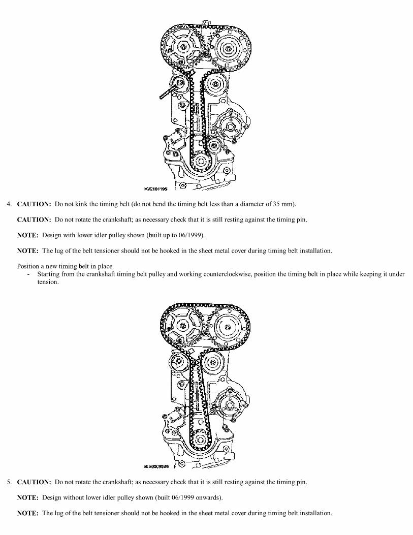
4. CAUTION: Do not kink the timing belt (do not bend the timing belt less than a diameter of 35 mm).
CAUTION: Do not rotate the crankshaft; as necessary check that it is still resting against the timing pin.
NOTE: Design with lower idler pulley shown (built up to 06/1999).
NOTE: The lug of the belt tensioner should not be hooked in the sheet metal cover during timing belt installation.
Position a new timing belt in place. - Starting from the crankshaft timing belt pulley and working counterclockwise, position the timing belt in place while keeping it under
tension.
5. CAUTION: Do not rotate the crankshaft; as necessary check that it is still resting against the timing pin.
NOTE: Design without lower idler pulley shown (built 06/1999 onwards).
NOTE: The lug of the belt tensioner should not be hooked in the sheet metal cover during timing belt installation.

Position a new timing belt in place. - Starting from the crankshaft timing belt pulley and working counterclockwise, position the timing belt in place while keeping it under
tension.
6. NOTE: Incorrect timing belt tension will cause incorrect valve timing.
Pre tension the timing belt. 1. Rotate the tensioner locating tab counterclockwise and insert the locating tab into the slot in the rear timing cover.2. Position the hex key slot in the tensioner adjusting washer to the 4 o'clock position.3. Tighten the attaching bold enough to seat the tensioner firmly against the rear timing cover, but still allow the tensioner adjusting
washer to be rotated using a 6mm hex key.
7. CAUTION: Tension the timing belt, working counterclockwise.
Using the hex key, rotate the adjusting washer counterclockwise until the notch in the pointer is centered over the index line on the locating tab(the pointer will move clockwise during adjustment).
8. While holding the adjusting washer in position, tighten the bolt.

9. NOTE: Hold the intake timing belt pulley with special tool to stop it from turning.
Tighten the timing belt pulleys. 1. Tighten the intake camshaft timing belt pulley bolt.
2. NOTE: Hold the exhaust camshaft by the hexagon with an open-ended wrench to stop it from turning.
Tighten the exhaust camshaft timing belt pulley bolt.
10. Remove the special tool. - Install the blanking plug.
11. Remove the special tool.
12. NOTE: Hold the camshaft by the hexagon with an open-ended wrench to stop it from turning.
Tighten the exhaust camshaft to stage 2.

13. NOTE: Turn the crankshaft two revolutions in the normal direction of rotation.
Check the valve timing by inserting the special tool. Correct it, if necessary.- Screw in special tool 303-574 and make sure that the crankshaft is touching it.- Insert special tool 303-465 into the camshafts; if necessary loosen the timing pulleys and correct the camshaft alignment.- Detach the special tools.
14. NOTE: Use a new blanking plug.
Install the blanking plug on the exhaust camshaft pulley.
15. NOTE: Valve cover tightening sequence: From the inside outwards, working diagonally.
Install the valve cover and spark plugs. 1. Install the spark plugs.2. Install the valve cover.
16. Install the HT wires and crankcase ventilation hose. 1. Connect the crankcase ventilation hose.2. Connect the HT wires to the spark plugs.

17. Install the appearance cover. 1. Install the eight bolts.2. Connect the solenoid valve electrical connector and press in the rubber seal.
18. Clip the throttle cable and the speed control cable to the appearance cover.
19. NOTE: Set the upper part of the engine front cover together with the center part in place.
Install the center part of the engine front cover.
20. NOTE: Check the seating of the upper part of the engine front cover gasket and correct as necessary.
Secure the upper part of the engine front cover.
21. Install the power steering pipe bracket to the engine lift eye.

22. NOTE: One bolt also holds the power steering line bracket.
Install the front support insulator.
23. Remove the floor jack.
24. Install the coolant expansion tank. - Attach the speed control cable (if equipped) to the coolant expansion tank.
25. Raise and support the vehicle.
Vehicles with automatic transaxle
26. NOTE: Verify that the center bolt is centered in the support insulator.
Tighten the center bolt of the right-hand engine support insulator.
Vehicles with manual transaxle

27. NOTE: Verify that the center bolt is centered in the support insulator.
Tighten the center bolt of the right-hand engine support insulator.
All Vehicles
28. NOTE: Verify that the center bolt is centered in the support insulator.
Tighten the center bolt of the left-hand engine support insulator.
29. Install the lower part of the engine front cover.
30. NOTE: Use the access hole in the bottom of transaxle case to stop engine rotating.
Install the crankshaft pulley/vibration damper.

31. NOTE: Note the accessory drive belt direction mark if belt is to be reused.
Install the accessory drive belt. 1. Install the belt idler pulley.2. Install the water pump pulley.3. Tension the belt tensioner clockwise and position the accessory drive belt in place.4. Tighten the water pump pulley bolts.
32. Install the right-hand front lower splash shield. - Install the right-hand front wheel.
33. Install the engine undershield (if equipped).34. Lower the vehicle.
35. Install the right-hand front wheel.
36. NOTE: When the battery has been disconnected and reconnected, some abnormal drive symptoms may occur while the vehicle relearns itsadaptive strategy. The vehicle may need to be driven 16 Km (10 miles) or more to relearn the strategy.

Connect the battery ground cable.
37. Check the fluid levels and correct as necessary.38. Check the routing of the vacuum hoses and wiring and secure them with cable ties.

5. Remove the engine underschield (if equipped)
6. Remove the right-hand front splash shield.
7. NOTE: Mark the accessory drive belt direction if the belt is to be reused.
Remove the accessory drive belt. 1. Loosen the water pump pulley bolts.2. Working clockwise, loosen the belt and remove it.3. Remove the water pump pulley.4. Remove the belt idler pulley.
8. NOTE: Using the access hole in the bottom of transaxle case to stop rotation of engine.
Remove the crankshaft pulley/vibration damper.

9. CAUTION: The removal of the lower part of the engine front cover is necessary to avoid damage to the timing belt.
Remove the lower part of the engine front cover.
Vehicles with manual transaxle
10. Loosen the center bolt of the right-hand engine support insulator two turns.
Vehicles with automatic transaxle
11. Loosen the center bolt of the right-hand engine support insulator two turns.
All Vehicles
12. Loosen the center bolt of the left-hand engine support insulator two turns.13. Lower the vehicle.
14. Detach the coolant expansion tank and position it to one side. - Disconnect the speed control cable (if equipped) from the coolant expansion tank.
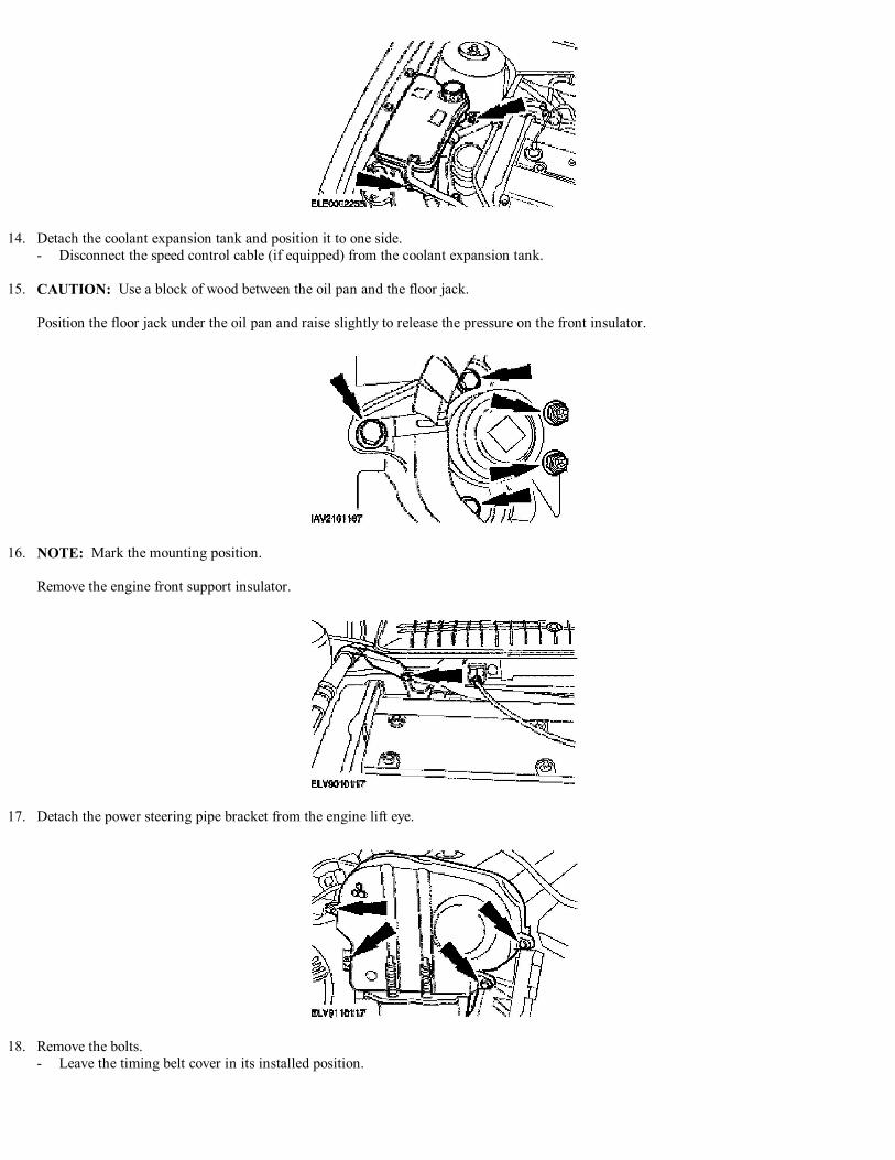
15. CAUTION: Use a block of wood between the oil pan and the floor jack.
Position the floor jack under the oil pan and raise slightly to release the pressure on the front insulator.
16. NOTE: Mark the mounting position.
Remove the engine front support insulator.
17. Detach the power steering pipe bracket from the engine lift eye.
18. Remove the bolts. - Leave the timing belt cover in its installed position.

19. Remove the center part of the engine front cover/front engine mounting bracket. - Take off the upper and the center covers.
20. Unclip the throttle cable and the speed control cable from the cylinder head appearance cover.
21. Remove the appearance cover. 1. Disconnect the solenoid valve electrical connector.2. Remove the appearance cover.
22. NOTE: Loosening sequence: From the outside inwards, working diagonally.
Remove the valve cover. 1. Disconnect the HT wires from the spark plugs.2. Disconnect the crankcase ventilation hose.3. Unscrew the 10 bolts.
23. CAUTION: The removal of the spark plug is necessary for the timing adjustment.
Remove the spark plugs.

24. NOTE: Set the crankshaft approximately to TDC on cylinder No. 1.
Detension the timing belt. 1. Unscrew the bolt four turns.2. Position the tensioner so the locating tab is at approximately the 4 o'clock position.3. Line up the hex key slot in the tensioner adjusting washer with the pointer that is located behind the pulley.
25. NOTE: To loosen the camshaft pulleys, hold the camshafts by the hexagon.
Loosen the camshaft pulleys. 1. Remove the blanking plug from the exhaust camshaft pulley.2. Loosen the exhaust camshaft pulley.3. Loosen the intake camshaft pulley.
26. Remove the timing belt.