1996 FEDERAL RADIONAVIGATION PLAN - Gaussgauss.gge.unb.ca/us1996frp.pdf · 1996 FEDERAL...
209
1996 FEDERAL RADIONAVIGATION PLAN Published by Department of Defense and Department of Transportation This document is available to the public through the National Technical Information Service, Springfield, Virginia 22161 DOT-VNTSC-RSPA-97-2/DOD-4650.5
Transcript of 1996 FEDERAL RADIONAVIGATION PLAN - Gaussgauss.gge.unb.ca/us1996frp.pdf · 1996 FEDERAL...

1996FEDERAL
RADIONAVIGATIONPLAN
Published byDepartment of Defenseand Department of Transportation
This document is available to the public through the National Technical Information Service, Springfield, Virginia 22161 DOT-VNTSC-RSPA-97-2/DOD-4650.5

NOTICE
The United States Government does not endorseproducts or manufacturers. Trade or manufacturers’
names appear herein solely because they are considered essential to the object of this report.

Letter of Promulgation
This letter promulgates the ninth edition of the Federal Radionavigation Plan, whichwas prepared jointly by the Departments of Defense and Transportation. Itsupersedes the 1994 Federal Radionavigation Plan.
The Federal Radionavigation Plan is published to provide information on themanagement of those Federally provided radionavigation systems used by both themilitary and civil sectors. It supports the planning, programming and implementingof air, marine, land and space navigation systems to meet the requirements shown inthe President’s budget submission to Congress. This plan is the official source ofradionavigation policy and planning for the Federal Government, and has beenprepared with the assistance of other Government agencies. The FederalRadionavigation Plan is revised biennially. Your suggestions for the improvement offuture editions are welcomed.
William S. Cohen Rodney E. SlaterSecretary of Defense Secretary of Transportation

RRRREEEEPPPPOOOORRRRTTTT DDDDOOOOCCCCUUUUMMMMEEEENNNNTTTTAAAATTTTIIIIOOOONNNN PPPPAAAAGGGGEEEE Form ApprovedOMB No. 0704-0188
Public reporting burden for this collection of information is estimated to average 1 hour per response, including the time forreviewing instructions, searching existing data sources, gathering and maintaining the data needed, and completing and reviewingthe collection of information. Send comments regarding this burden estimate or any other aspect of this collection of information,including suggestions for reducing this burden, to Washington Headquarters Services, Directorate for information Operations andReports, 1215 Jefferson Davis Highway, Suite 1204, Arlington, VA 22202-4302, and to the Office of Management and Budget, PaperworkReduction Project (0704-0188), Washington, DC 20503.
1. AGENCY USE ONLY (Leave blank) 2. REPORT DATE
July 19973. REPORT TYPE AND DATES COVERED
Final ReportJanuary 1994 - December 1996
4. TITLE AND SUBTITLE
1996 Federal Radionavigation Plan5. FUNDING NUMBERS
OP70J/T7037
6. AUTHOR(S)
7. PERFORMING ORGANIZATION NAME(S) AND ADDRESS(ES)
U.S. Department of Transportation (OST/P) U.S. Department of Defense (USD/A&T)Washington, DC 20590 Washington, DC 20301
8. PERFORMING ORGANIZATION REPORT NUMBER
DOD-4650.5/DOT-VNTSC-RSPA-97-2
9. SPONSORING/MONITORING AGENCY NAME(S) AND ADDRESS(ES)
U.S. Department of Transportation (OST/P)Washington,DC 20590
U.S. Department of Defense (USD/A&T)Washington,DC 20301
10. SPONSORING/MONITORING AGENCY REPORT NUMBER
DOT-VNTSC-RSPA-97-2DOD-4650.5
11. SUPPLEMENTARY NOTES
12a. DISTRIBUTION/AVAILABILITY STATEMENT
This document is available to the public through the NationalTechnical Information Service, Springfield, VA 22161
12b. DISTRIBUTION CODE
13. ABSTRACT (Maximum 200 words)
The Federal Radionavigation Plan (FRP) delineates policies and plans for radionavigation services provided by the U.S. Governmentto ensure efficient use of resources and full protection of national interests. Developed jointly by the U.S. Departments ofDefense and Transportation, the FRP sets forth the Federal interagency approach to the implementation and operation ofradionavigation systems.
The FRP is updated biennially. This ninth edition describes respective areas of authority and responsibility, and provides amanagement structure by which the individual operating agencies will define and meet requirements in a cost-effective manner. Moreover, this edition contains the current policy on the radionavigation systems mix. The constantly changing radionavigationuser profile and rapid advancements in systems technology, require that the FRP remain as dynamic as the issues it addresses. Thisedition of the FRP builds on the foundation laid by previous editions and further develops national plans towards providing anoptimum mix of radionavigation systems for the foreseeable future.
14. SUBJECT TERMS
Navigation Planning, Radionavigation System, Navigation Requirements, Position Location, GlobalPositioning System
15. NUMBER OF PAGES
212
16. PRICE CODE
17. SECURITY CLASSIFICATION OF REPORT
Unclassified
18. SECURITY CLASSIFICATION OF THIS PAGE
Unclassified
19. SECURITY CLASSIFICATION OF ABSTRACT
Unclassified
20. LIMITATION OF ABSTRACT
NSN 7540-01-280-5500 Standard Form 298 (Rev. 2-89)Prescribed by ANSI Std. 239-18298-102
Preface
The Department of Defense (DOD) and the Department of Transportation (DOT)have developed the ninth edition of the Federal Radionavigation Plan (FRP) toensure full protection of national interests and efficient use of resources. The plansets forth the Federal interagency approach to the implementation and operation ofFederally provided, common use (civil and military) radionavigation systems.
The FRP is a review of existing and planned radionavigation systems used in air,land, marine, and space navigation and for purposes other that navigation in terms ofuser requirements and current status. The FRP contents reflect DOD responsibilityfor national security, as well as DOT responsibilities for public safety andtransportation economy.
The plan is updated biennially. The established DOD/DOT interagency managementapproach allows continuing control and review of U.S. radionavigation systems.Your inputs for the next edition of this plan are welcome. Interested parties andadvisory groups from the private sector are invited to submit their inputs to theChairman of the DOT Positioning and Navigation (POS/NAV) Working Group(Attn: OST/P-7), Department of Transportation, Office of the Assistant Secretary forTransportation Policy, Washington, D.C. 20590.
Meetings and discussions with radionavigation user groups, to give them theopportunity to exchange ideas and comments on this document, are planned to beheld before the preparation of the next FRP.
iii

Table of Contents
1. Introduction to the Federal Radionavigation Plan ........................ 1-1
1.1 Background ........................................................................................ 1-1
1.2 Purpose............................................................................................... 1-3
1.3 Scope.................................................................................................. 1-3
1.4 Objectives .......................................................................................... 1-4
1.5 Policies and Practices ........................................................................ 1-4
1.6 DOD/DOT Policy on the Radionavigation System Mix ................... 1-6
1.7 DOD Responsibilities ........................................................................ 1-13
1.7.1 Operational Management................................................. 1-14
1.7.2 Administrative Management............................................ 1-16
1.8 DOT Responsibilities......................................................................... 1-16
1.9 DOD/DOT Joint Responsibilities ...................................................... 1-22
1.10 Department of State Responsibilities ................................................ 1-22
1.11 Radionavigation Systems Selection Considerations.......................... 1-23
1.11.1 Background and Approach .............................................. 1-23
1.11.2 Special Military Considerations ...................................... 1-24
1.11.3 Technical Considerations ................................................. 1-25
1.11.4 Economic Considerations ................................................ 1-26
1.11.5 Institutional Considerations ............................................. 1-26
1.11.6 International Considerations ............................................ 1-28
1.11.7 Radio Frequency Spectrum Considerations .................... 1-29
1.11.8 Criteria for Selection........................................................ 1-31
v

2. Radionavigation System User Requirements .............................. 2-1
2.1 Civil Radionavigation System Requirements.................................... 2-2
2.1.1 Process ............................................................................. 2-2
2.1.2 User Factors ..................................................................... 2-3
2.2 Civil Air Radionavigation Requirements .......................................... 2-4
2.2.1 Phases of Air Navigation ................................................. 2-4
2.2.2 General Requirements for Aviation Navigation Systems .......................................... 2-4
2.2.3 Navigation Signal Error Characteristics .......................... 2-7
2.2.4 Current Aviation Navigation Accuracy Requirements for Phases of Flight .................................. 2-8
2.2.5 Future Aviation Navigation Requirements ...................... 2-14
2.3 Civil Marine Radionavigation Requirements .................................... 2-16
2.3.1 Phases of Marine Navigation........................................... 2-16
2.3.2 Current Marine Navigation Requirements ...................... 2-18
2.3.3 Future Marine Navigation Requirements ........................ 2-26
2.4 Space Radionavigation Requirements ............................................... 2-28
2.4.1 Mission Phases................................................................. 2-28
2.4.2 Current Space Radionavigation Requirements................ 2-28
2.5 Civil Land Radionavigation Requirements ....................................... 2-30
2.5.1 Categories of Land Transportation .................................. 2-30
2.5.2 Current Land Transportation Requirements .................... 2-32
2.6 Requirements for Non-Navigation Applications ............................... 2-34
2.6.1 Geodesy and Surveying ................................................... 2-35
2.6.2 Mapping, Charting and Geographic Information Systems (GIS).............................................. 2-35
2.6.3 Geophysical Applications ................................................ 2-36
2.6.4 Meteorological Applications............................................ 2-36
2.6.5 Time and Frequency Applications ................................... 2-37
2.6.6 Summary of Requirements .............................................. 2-37
2.7 Military Radionavigation Requirements............................................ 2-39
2.7.1 General Requirements...................................................... 2-39
2.7.2 Service Requirements ...................................................... 2-41
3. Radionavigation System Use........................................................... 3-1
3.1 Existing Systems Used in the Phases of Navigation......................... 3-1
3.1.1 Air Navigation ................................................................. 3-2
3.1.2 Marine Navigation ........................................................... 3-4
vi

3.1.3 Land Navigation .............................................................. 3-5
3.1.4 Uses Other Than Navigation ........................................... 3-5
3.1.5 Space Applications........................................................... 3-6
3.2 Existing and Developing Systems - Status and Plans ....................... 3-6
3.2.1 Global Positioning System (GPS) ................................... 3-6
3.2.2 GPS Augmentations ........................................................ 3-9
3.2.3 Loran-C............................................................................ 3-14
3.2.4 Omega .............................................................................. 3-15
3.2.5 VOR and VOR/DME....................................................... 3-16
3.2.6 TACAN ............................................................................ 3-17
3.2.7 ILS.................................................................................... 3-18
3.2.8 MLS ................................................................................. 3-20
3.2.9 Aeronautical Nondirectional Beacons (NDBs) ............... 3-21
3.2.10 Maritime Radiobeacons ................................................... 3-22
3.3 Interoperability of Radionavigation Systems .................................... 3-24
3.3.1 Overview.......................................................................... 3-24
3.3.2 GPS/GLONASS............................................................... 3-24
4. Radionavigation System Research and Development Summary.................................................................... 4-1
4.1 Overview............................................................................................ 4-1
4.2 DOT R&D.......................................................................................... 4-3
4.2.1 Civil Aviation................................................................... 4-3
4.2.2 Civil Marine..................................................................... 4-9
4.2.3 Civil Land ........................................................................ 4-11
4.3 NASA R&D ....................................................................................... 4-15
4.4 NOAA R&D ..................................................................................... 4-16
4.5 DOD R&D ......................................................................................... 4-16
Appendix A. System Descriptions ........................................................ A-1
A.1 System Parameters............................................................................. A-1
A.1.1 Signal Characteristics ...................................................... A-2
A.1.2 Accuracy .......................................................................... A-2
A.1.3 Availability....................................................................... A-3
A.1.4 Coverage .......................................................................... A-3
A.1.5 Reliability......................................................................... A-4
A.1.6 Fix Rate............................................................................ A-4
A.1.7 Fix Dimensions ................................................................ A-4
vii

A.1.8 System Capacity .............................................................. A-4
A.1.9 Ambiguity ........................................................................ A-4
A.1.10 Integrity............................................................................ A-4
A.2 System Descriptions .......................................................................... A-4
A.2.1 GPS .................................................................................. A-5
A.2.2 Augmentations to GPS .................................................... A-8
A.2.3 Loran-C............................................................................ A-17
A.2.4 Omega .............................................................................. A-22
A.2.5 VOR, VOR/DME, and TACAN ...................................... A-25
A.2.6 ILS.................................................................................... A-32
A.2.7 MLS ................................................................................. A-35
A.2.8 Aeronautical Radiobeacons ............................................. A-38
A.2.9 Maritime Radiobeacons ................................................... A-41
A.3 Navigation Information Services....................................................... A-42
A.3.1 USCG Navigation Information Service........................... A-42
A.3.2 GPS NOTAM/Aeronautical Information System............ A-43
Appendix B. Reference Systems .......................................................... B-1
B.1 Map and Chart Reference Systems.................................................... B-1
B.2 Nautical Charts .................................................................................. B-2
B.3 Aeronautical Charts ........................................................................... B-3
B.4 Electronic Chart Display Information System (ECDIS) ................... B-4
Appendix C. Definitions .......................................................................... C-1
Appendix D. Glossary .............................................................................. D-1
References.................................................................................................. R-1
Index ............................................................................................................. I-1
viii
List of Figures
Figure 1-1. Interagency GPS Executive Board Management Structure........................................................... 1-2
Figure 1-2. DOD Navigation Management Structure .............................. 1-15
Figure 1-3. DOT Navigation Management Structure............................... 1-17
Figure 2-1. RNAV Nonprecision Approach Protected Areas ................... 2-14
Figure 3-1. Estimated Current U.S. Radionavigation System User Population...................................................................... 3-3
Figure 3-2. Radionavigation Systems Operating Plan ............................. 3-7
Figure 4-1. Development of GPS Performance Standards for Civil Avionics.................................................. 4-7
Figure A-1. USCG DGPS Navigation Service Architecture..................... A-11
Figure A-2. Proposed Conus, Alaska and Hawaii Maritime DGPS Coverage..................................................................... A-13
Figure A-3. WAAS Architecture ............................................................... A-15
Figure A-4. Coverage Provided by U.S. Operated or Supported Loran-C Stations .................................................. A-20
Figure A-5. NIS Information Flow............................................................ A-45
Figure A-6. GPS NOTAM/Aeronautical Information Distribution System ............................................................... A-46
ix
x
List of Tables
Table 2-1. Controlled Airspace Navigation Accuracy Requirements ..... 2-9
Table 2-2. Current Maritime User Requirements for Purposes of System Planning and Development - Inland Waterway Phase.......................................................... 2-19
Table 2-3. Current Maritime User Requirements/Benefits for Purposes of System Planning and Development - Harbor Entrance and Approach Phase................................... 2-20
Table 2-4. Current Maritime User Requirements/Benefits for Purposes of System Planning and Development - Coastal Phase ......................................................................... 2-21
Table 2-5. Current Maritime User Requirements/Benefits for Purposes of System Planning and Development - Ocean Phase........................................................................... 2-22
Table 2-6. ITS User Services Requiring Use of Radionavigation.......... 2-31
Table 2-7. Land Transportation Positioning/Navigation System Accuracy Needs/Requirements ................................. 2-33
Table 2-8. Requirements for Surveying, Timing and Other Applications ........................................................................... 2-38
Table 4-1. Examples of ITS Operational Tests Using GPS.................... 4-13
Table 4-2. Positive Train Control Projects Using GPS........................... 4-15
Table A-1. GPS/SPS Characteristics (Signal-In-Space) .......................... A-6
Table A-2. Loran-C System Characteristics (Signal-In-Space)............... A-18
Table A-3. Omega System Characteristics (Signal-In-Space)................. A-23
Table A-4. VOR and VOR/DME System Characteristics (Signal-In-Space) ................................................................... A-26
Table A-5. TACAN System Characteristics (Signal-In-Space)............... A-31
Table A-6. ILS Characteristics (Signal-In-Space) ................................... A-33
Table A-7. Aircraft Marker Beacons ....................................................... A-35
Table A-8. MLS Characteristics (Signal-In-Space)................................. A-37
Table A-9. Radiobeacon System Characteristics (Signal-In-Space) ................................................................... A-39
Table A-10. NIS Services .......................................................................... A-44
xi

xii
Executive Summary
The Federal Radionavigation Plan (FRP) delineates policies and plans for Federallyprovided radionavigation systems. It also recognizes that the existence of privatelyoperated radiodetermination systems may impact future government radionavigationplanning. This plan describes areas of authority and responsibility and provides amanagement structure by which the individual operating agencies can define andmeet radionavigation requirements in a cost-effective manner. It is the official sourceof radionavigation policy and planning for the Federal Government. This edition ofthe FRP updates and replaces the 1994 FRP and incorporates common-useradionavigation systems (i.e., systems used by both civil and military sectors)covered in the Department of Defense (DOD) Chairman, Joint Chiefs of Staff(CJCS) Master Navigation Plan (MNP). The MNP covers many radionavigationsystems used exclusively by the military, and has not been superseded by the FRP.
This document describes the various phases of navigation and other applications ofradionavigation services, and provides current and anticipated requirements for each.As requirements change, radionavigation systems may be added or deleted insubsequent revisions to this plan. Where there is a potential for radio spectrumcurrently supporting these radionavigation systems to be used for implementation ofnew aeronautical systems, these have been identified within the text of the FRP.
The FRP covers common-use, Federally operated systems. These systems aresometimes used in combination or with other systems. Privately operated systemsare recognized in the interest of providing a complete picture of U.S.radionavigation.
xiii

The systems covered in this plan are:
• GPS
• Augmentations to GPS
• Loran-C
• Omega
• VOR and VOR/DME
• TACAN
• ILS
• MLS
• Transit
• Radiobeacons
A major goal of DOD and the Department of Transportation (DOT) is to select amix of these common-use (civil and military) systems which meets diverse userrequirements for accuracy, reliability, availability, integrity, coverage, operationalutility, and cost; provides adequate capability for future growth; and eliminatesunnecessary duplication of services. Selecting a future radionavigation systems mixis a complex task, since user requirements vary widely and change with time. Whileall users require services that are safe, readily available and easy to use, militaryrequirements stress unique defense capabilities, such as performance underintentional interference, operations in high-performance vehicles, worldwidecoverage, and operational capability in severe environmental conditions. Costremains a major consideration which must be balanced with a needed operationalcapability.
Navigation requirements range from those for small single-engine aircraft or smallvessels, which are cost-sensitive and may require only minimal capability, to thosefor highly sophisticated users, such as airlines, large vessel operators, or spacecraft,to whom accuracy, flexibility, and availability may be more important than initialcost. The emerging applications of land navigation will most likely cover the entirerange of requirements. The selection of an optimum mix to satisfy user needs, whileholding the number of systems and costs to a minimum, involves complexoperational, technical, institutional, international and economic tradeoffs. This planestablishes a means to address user inputs and questions, and arrive at an optimummix determination. This edition of the FRP builds on the foundation laid by previouseditions and further develops national plans toward providing an optimum mix ofradionavigation systems.
The constantly changing radionavigation user profile and rapid advancements insystems technology require that the FRP remain as dynamic as the issues itaddresses. This issue of the FRP contains the current policy on the radionavigationsystems mix.
xiv

This document is composed of the following sections:
Section 1 - Introduction to the Federal Radionavigation Plan: Delineates thepurpose, scope and objectives of the plan, presents the DOD and DOT authority andresponsibilities for providing radionavigation services, and describes the DOD andDOT policies and plans for the radionavigation system mix.
Section 2 - Radionavigation System User Requirements: Provides civil andmilitary requirements for air, space, land, and marine navigation, and non-navigationapplications of radionavigation systems.
Section 3 - Radionavigation System Use: Describes how the variousradionavigation systems are used in meeting civil requirements, and the status andplans for each system.
Section 4 - Radionavigation System Research and Development Summary:Presents the research and development efforts planned and conducted by DOT,DOD, and other Federal organizations.
Appendix A - System Descriptions: Describes present and planned navigationsystems in terms of ten major parameters: signal characteristics, accuracy,availability, coverage, reliability, fix rate, fix dimensions, system capacity,ambiguity, and integrity.
Appendix B - Reference Systems: Discusses geodetic datums and the referencesystems based upon them.
Appendix C - Definitions
Appendix D - Glossary
References
Index
xv

1Introduction to the Federal
Radionavigation Plan
This section describes the background, purpose, and scope of the FederalRadionavigation Plan (FRP). It summarizes the events leading to the preparation ofthis document, the national objectives for coordinating the planning ofradionavigation services, national policy on radionavigation systems, andradionavigation authority and responsibility.
1.1 Background
The first edition of the FRP was released in 1980 as part of a Presidential Report toCongress, prepared in response to the International Maritime Satellite (INMARSAT)Act of 1978. It marked the first time that a joint Department of Transportation(DOT) and Department of Defense (DOD) plan for common-use (both civil andmilitary) systems had been developed. Now, this biennially-updated plan serves asthe planning and policy document for all present and future Federally providedcommon-use radionavigation systems.
The 1979 DOD/DOT Interagency Agreement for joint radionavigation planning, aswell as for the development and publication of the FRP, was renewed in 1990. Thisagreement recognizes the need to coordinate all Federal radionavigation systemplanning and to attempt, wherever consistent with operational requirements, toutilize common systems. A memorandum of agreement between the DOD and DOTon the civil use of the Global Positioning System (GPS) signed in January 1993established policies and procedures to ensure an effective working relationshipbetween the two Departments regarding the civil use of GPS. The March 28, 1996Presidential Decision Directive (PDD) on GPS provides a comprehensive nationalpolicy and guidelines on the future management and use of GPS. An Interagency
1 - 1
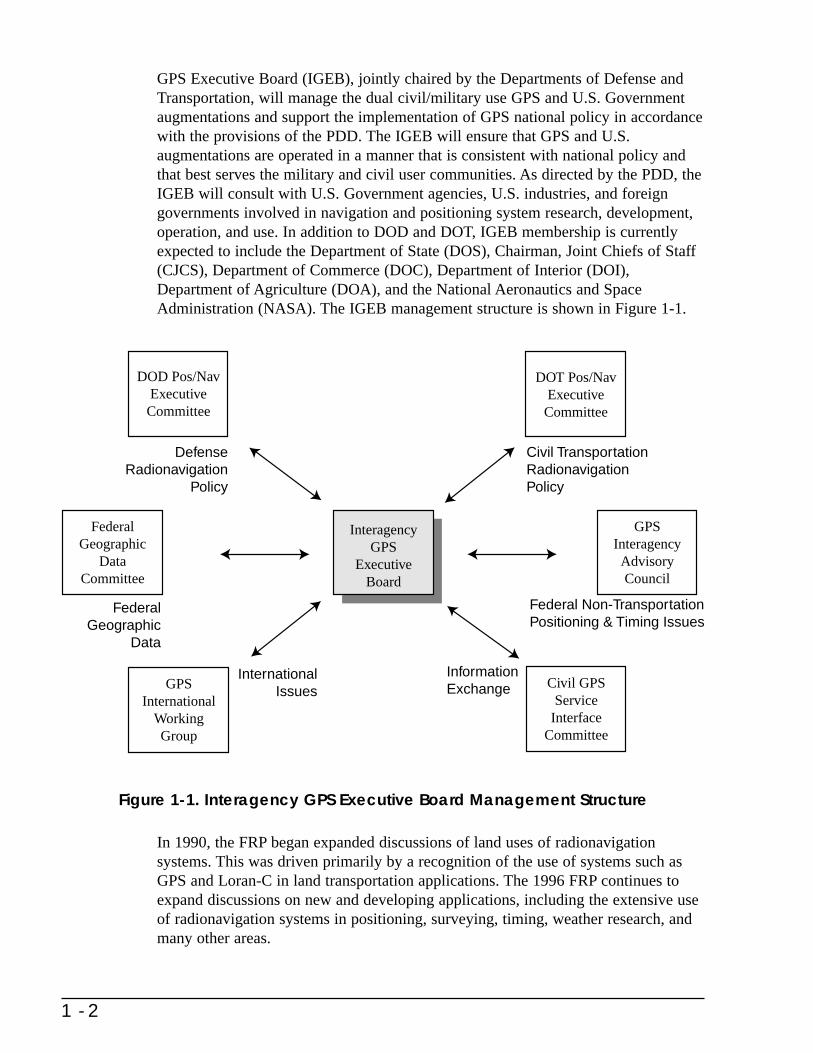
GPS Executive Board (IGEB), jointly chaired by the Departments of Defense andTransportation, will manage the dual civil/military use GPS and U.S. Governmentaugmentations and support the implementation of GPS national policy in accordancewith the provisions of the PDD. The IGEB will ensure that GPS and U.S.augmentations are operated in a manner that is consistent with national policy andthat best serves the military and civil user communities. As directed by the PDD, theIGEB will consult with U.S. Government agencies, U.S. industries, and foreigngovernments involved in navigation and positioning system research, development,operation, and use. In addition to DOD and DOT, IGEB membership is currentlyexpected to include the Department of State (DOS), Chairman, Joint Chiefs of Staff(CJCS), Department of Commerce (DOC), Department of Interior (DOI),Department of Agriculture (DOA), and the National Aeronautics and SpaceAdministration (NASA). The IGEB management structure is shown in Figure 1-1.
Figure 1-1. Interagency GPS Executive Board Management Structure
In 1990, the FRP began expanded discussions of land uses of radionavigationsystems. This was driven primarily by a recognition of the use of systems such asGPS and Loran-C in land transportation applications. The 1996 FRP continues toexpand discussions on new and developing applications, including the extensive useof radionavigation systems in positioning, surveying, timing, weather research, andmany other areas.
1 - 2
GPS International
WorkingGroup
DOD Pos/NavExecutiveCommittee
DOT Pos/NavExecutive
Committee
GPS InteragencyAdvisory Council
Civil GPSService
InterfaceCommittee
FederalGeographic
DataCommittee
InteragencyGPS
ExecutiveBoard
DefenseRadionavigation
Policy
FederalGeographic
Data
InternationalIssues
InformationExchange
Federal Non-TransportationPositioning & Timing Issues
Civil TransportationRadionavigationPolicy
The Federal Government holds open meetings every two years to provide the usercommunity with the opportunity to comment on Federal radionavigation systempolicies and plans as published in the FRP. In 1996, user meetings were held inCambridge, MA and Boulder, CO. The meetings were very well attended, with abroad spectrum of users representing the private sector; Federal, state, and localgovernment agencies; and academic institutions. Aviation, land, marine, and spacenavigation interests were represented, as well as other applications forradionavigation systems, such as precise timing, positioning, geodesy and surveying,and weather research. Major comments from the audience included widespreadsupport for use of GPS; concerns with relying on a single radionavigation system(i.e., GPS) without backup or complementary systems; support from the generalaviation community for continuing Loran-C beyond the current phaseout date; andsupport from the international meteorological community for continuing Omegabeyond the current phaseout date. DOT plans to continue to hold discussions withuser groups to address these concerns.
The need to consolidate and reduce the number of navigation systems as GPS isphased in is a major objective of DOD and DOT. The constantly changingradionavigation user profile and rapid advancements in systems technology requirethat the FRP remain as dynamic as the issues it addresses. The current DOD/DOTpolicy on the radionavigation systems mix is presented in Section 1.6.
1.2 Purpose
The purpose of the FRP is to:
• Present an integrated Federal policy and plan for all common-use civil andmilitary radionavigation systems.
• Provide a document for specifying radionavigation requirements andaddressing common-use systems and applications.
• Outline an approach for consolidating radionavigation systems.
• Provide government radionavigation system planning information andschedules.
• Define and clarify new or unresolved common-use radionavigation systemissues.
• Provide a focal point for user input.
1.3 Scope
This plan covers Federally provided, common-use radionavigation systems,acknowledging that these systems can be used for other purposes. It also brieflyaddresses privately owned systems such as Radar Transponder Beacons (RACONs),and others that interface with or impact Federally provided systems. The plan does
1 - 3

not include systems which mainly perform surveillance and communicationfunctions.
The major systems subject to the planning process described in this FRP are:
• GPS
• Augmentations to GPS
• Loran-C
• Omega
• VOR and VOR/DME
• TACAN
• ILS
• MLS
• Radiobeacons
1.4 Objectives
The radionavigation policy of the United States has evolved through statute, usage,and in the interest of national defense and public safety. The objectives of U.S.Government radionavigation system policy are to:
• Strengthen and maintain national security.
• Provide safety of travel.
• Promote efficient transportation.
• Ensure environmental protection.
• Support peaceful civil, commercial, and scientific applications ofradionavigation systems.
1.5 Policies and Practices
The following U.S. Government policies and practices support the above objectives:
a. Implementation and operation of radio aids to navigation. Services whichcontribute to safe, expeditious, and economic air, land and maritime commerceand which support United States national security interests are provided.
b. Installation and operation of radionavigation systems in accordance withinternational agreements.
1 - 4

c. Avoidance of unnecessary duplication of radionavigation systems and services.The highest degree of commonality and system utility between military and civilusers is sought through early consideration of mutual requirements.
d. Recognition of electromagnetic spectrum requirements in the planning andmanagement of radionavigation systems.
e. Promotion of transportation safety and environmental protection by requiringcertain vessels and aircraft to be fitted with radionavigation equipment as acondition for operating in the controlled airspace or navigable waters of theUnited States.
f. Evaluation of domestic and foreign radio aids to navigation, with support for thedevelopment of those systems having the potential to meet unfulfilledoperational requirements; those offering major economic advantages overexisting systems; and those providing significant benefits in the national interest.
g. Establishment of suitable system transition periods based on user equipage andacceptance, budgetary considerations, and the public interest.
h. Promotion of international exchange of scientific and technical informationconcerning radionavigation aids.
i. Guidance and assistance in siting, testing, evaluating, and operating non-Federaland private radio aids to meet unique aviation and land transportationrequirements.
j. Promotion of national and international standardization of civil and militaryradionavigation aids.
k. Establishment, maintenance, and dissemination of system and signal standardsand specifications.
l. Development, implementation, and operation of the minimum specialradionavigation aids and services for military operations.
m. Availability of radionavigation systems operated by the U.S. Government subjectto direction by the National Command Authorities (NCA) in the event of a realor potential threat of war or impairment to national security.
n. Provision of the GPS Standard Positioning Service (SPS) for continuous,worldwide civil use at the highest level of accuracy consistent with U.S. nationalsecurity interests.
o. Enhancement of GPS for civil applications.
p. Encouraging acceptance and integration of GPS into peaceful civil, commercial,and scientific applications worldwide.
q. Equipping of military vehicles, as appropriate, to satisfy civil aviation andmaritime navigation safety requirements. However, the primary concern will be
1 - 5

that U.S. military vehicles and users are equipped with navigation systems whichbest satisfy mission requirements. Standardization, although important, may bedisregarded when unique military systems provide the capability to operatesafely without reference to civil radionavigation systems.
r. Establishment of mechanisms, where practical, for users of Federally providedradionavigation systems to bear their fair share of the costs (except for directcharges for basic GPS signals) for development, procurement, operation, andmaintenance of these systems.
s. Provision, through DOD/DOT interagency agreements, of comprehensivemanagement for all Federally provided common-use radionavigation systems.
t. Ensuring, in accordance with the national policy found in OMB Circular A-76(Ref. 1), that the private sector is considered in the design, development,installation, operation, and maintenance of all equipment and systems required toprovide common-use radionavigation aids in support of this FRP (within theconstraints of national security).
1.6 DOD/DOT Policy on the Radionavigation System Mix
The Department of Transportation is responsible under 49 United States Code(U.S.C.) Section 301 for ensuring safe and efficient transportation. Radionavigationsystems play an important role in carrying out this responsibility. The two mainelements within DOT that operate radionavigation systems are the United StatesCoast Guard (USCG) and the Federal Aviation Administration (FAA). The AssistantSecretary for Transportation Policy (OST/P) is responsible for coordinatingradionavigation planning within DOT and with other civil Federal elements.
The USCG provides U.S. aids to navigation for safe and efficient marine navigation.The FAA has the responsibility for the development and implementation ofradionavigation systems to meet the needs for safe and efficient air navigation, aswell as for control of all civil and military aviation, except for military aviationneeds peculiar to warfare and primarily of military concern. The FAA also has theresponsibility to operate aids to air navigation required by international treaties.
Other elements within DOT participate in radionavigation planning. These elementsinclude the St. Lawrence Seaway Development Corporation (SLSDC), the MaritimeAdministration (MARAD), the Federal Highway Administration (FHWA), theIntelligent Transportation Systems Joint Program Office (ITS-JPO), the FederalRailroad Administration (FRA), the National Highway Traffic Safety Administration(NHTSA), the Federal Transit Administration (FTA), the Research and SpecialPrograms Administration (RSPA), and the Bureau of Transportation Statistics (BTS).
The Department of Defense is responsible for developing, testing, evaluating,implementing, operating, and maintaining aids to navigation and user equipmentrequired for national defense and ensuring that military vehicles operating inconsonance with civil vehicles have the necessary navigational capabilities.
1 - 6

All common-use systems operating or planned were considered in developing thepolicy on the mix of Federally provided radionavigation systems. The statement thatfollows is the U.S. Federal radionavigation policy and plans.
1 - 7

Federal Radionavigation System Policy and Plans
(1996 Federal Radionavigation Plan)
Purpose: This statement sets forth the policy and plans for Federally providedradionavigation systems.
Objectives: The Federal Government operates radionavigation systems as one of thenecessary elements to enable safe transportation and encouragecommerce within the United States. It is a goal of the Government toprovide this service in a cost-effective manner. In order to meet both civiland military radionavigation needs, the Government has established aseries of radionavigation systems over a period of years. Each systemutilizes the latest technology available at the time of introduction to meetexisting or unfulfilled needs. This statement addresses the conditionsunder which each system may be part of Federal radionavigation systempolicy and plans.
The Department of Defense (DOD) has deployed a new dual-use (civiland military) radionavigation system, the Global Positioning System(GPS). This system meets or exceeds the accuracy and coverage of manyother radionavigation systems. Consequently, as the full civil potential ofGPS is realized, the Federal Government expects to phase outradionavigation systems that are no longer required.
Decisions to discontinue Federal operation of existing systems willdepend upon many factors including: (a) resolution of GPS accuracy,availability, coverage, integrity, financial, and institutional issues; (b)determination that the resulting systems mix meets civil and militaryneeds currently met by existing systems; (c) availability of civil userequipment at economically acceptable prices; (d) establishment of asuitable transition period based on user equipment and acceptance,budgetary considerations, and the public interest, and (e) resolution ofinternational commitments.
Although radionavigation systems are established primarily for safety oftransportation, they also provide significant benefits to other civil,commercial, and scientific users. In recognition of this, any changes toFederal operation of radionavigation systems will consider these needs.
Radionavigation systems operated by the U.S. Government are availablesubject to direction by the National Command Authorities (NCA) in theevent of a real or potential threat of war or impairment to national
1 - 8
security. Operating agencies may cease operations or changecharacteristics and signal formats of radionavigation systems during adire national emergency. All communication links, including those usedto transmit differential GPS corrections and other GPS augmentations,are also subject to the direction of the NCA.
Individual System Plans:
GPS: GPS, a 24-satellite-based radionavigation system operated by the DODand managed by the Interagency GPS Executive Board, provides twolevels of service - a Standard Positioning Service (SPS), which uses theC/A code on the L1 frequency, and a Precise Positioning Service (PPS)which uses the P(Y) code on both L1 and L2 frequencies. SPS isavailable to all users on a continuous, worldwide basis, for theforeseeable future, free of any direct user charge. The specific capabilitiesprovided by SPS are established by DOD and DOT and are published inthe Global Positioning System Standard Positioning Service SignalSpecification*, available through the USCG Navigation InformationService.
Access to the PPS component of the GPS service is made available toU.S. Federal and Allied Government (civil and military) users on a case-by-case basis through special Memoranda of Agreement with the DOD.
Although the L2 is not part of the Standard Positioning Service, manycivil users currently employ dual frequency receiver technologies tosupport their requirements. DOT and DOD have determined thatavailability of a second coded signal is essential for these critical uses ofGPS. Until such time as a second coded civil GPS signal is operational,the DOD will not intentionally reduce the current received minimumradio frequency signal strength of the P(Y)-code signal on the L2 link, asspecified in the Interface Control Document (ICD) GPS 200, nor will theDOD intentionally alter the modulation codes, as known today, togenerate the current P(Y)-code signal on the L2 link. This does notpreclude additions of other codes or modifications to the L2 signal whichdo not change or make unusable the current L2 P(Y)-coded signal and itsmodulation codes.
Regarding pursuit of a second coded civil signal and its frequency, DODand DOT will jointly complete by March 1998 identification of a secondcoded civil frequency and a detailed plan for providing the second codedcivil signal.
1 - 9
* U.S. Department of Defense, 2nd Edition, June 2, 1995.

Augmentations
to GPS: When augmented to satisfy civil requirements for accuracy, coverage,availability and integrity, GPS will be the primary Federally providedradionavigation system for the foresable future.
Augmentations to GPS are enhancements to the basic GPS system tomeet unique requirements. Augmentations to GPS fall into twocategories: 1) differential GPS (DGPS), and 2) additional inputs fromnon-GPS navigation systems, equipment, or techniques.
The U.S. Government will not constrain the peaceful use of SPS-basedDGPS services as long as applicable U.S. statutes and internationalagreements are adhered to.
Maritime DGPS: The USCG declared Initial Operational Capability(IOC) for maritime DGPS service on January 30, 1996. The USCGsystem provides service for coastal coverage of the continental U.S., theGreat Lakes, Puerto Rico, portions of Alaska and Hawaii, and portions ofthe Mississippi River Basin. Maritime DGPS uses fixed GPS referencestations which broadcast pseudo-range corrections using radionavigationradiobeacons. The USCG DGPS system provides radionavigationaccuracy better than 10 meters (2 drms) for U.S. harbor entrance andapproach areas. The USCG is continuing to validate the current system’sability to meet the needs of the harbor entrance and approach and inlandphases of navigation.
Aeronautical Augmentations to GPS/SPS (WAAS/LAAS): TheFederal Aviation Administration (FAA), in cooperation with other DOTorganizations and DOD, is augmenting the GPS/SPS with both a widearea and a local area system. The Wide Area Augmentation System(WAAS) can provide the required accuracy, integrity, and availability tobe the primary means of navigation for all phases of flight from en routeto Category I approaches. The FAA plans to commission an initial WAAScapability in 1999, at which time it is expected to be certified as aprimary means of navigation for en route and terminal operations andlimited precision approach service. WAAS is envisioned to reach its fulloperational capability in 2001 with multiple redundancy to support allphases of flight from en route to Category I precision approach. TheLocal Area Augmentation System (LAAS) is expected to provide therequired accuracy, integrity, and availability for Category II and CategoryIII precision approaches, as well as to increase the availability of CAT Isystems.
The FAA will continue to evaluate progress in transitioning to satellite-based navigation and landing technology. By 2003, the FAA expects todetermine whether to alter its schedule for terminating remaining ground-
1 - 10
based systems. This determination will consider the performance of GPSand its augmentations, user acceptance of satellite technology, and userequipage with satellite-based avionics. Based on the results of itsevaluation and on anticipated budgetary constraints, the FAA may need toaccelerate the decommissioning of the remaining ground-based systems.
Loran-C: Loran-C provides coverage for maritime navigation in U.S. coastal areas.It provides navigation, location, and timing services for both civil andmilitary air, land and marine users. Loran-C is approved as asupplemental air navigation system and also serves a large number ofusers that operate under Visual Flight Rules (VFR). The Loran-C systemserves the 48 conterminous states, their coastal areas, and parts of Alaska.The U.S. plans to terminate Loran-C operations on December 31, 2000.The Coast Guard Authorization Act of 1996 requires, however, that theDOT prepare a report on the future use and funding of Loran-C. Thereport will be developed in consultation with the users of the Loran-Csystem and in cooperation with the Secretary of Commerce.
Omega: Omega provides global radionavigation coverage and primarily servesmaritime, aviation, and weather users. The U.S. operates Omega underbilateral agreements with six partner nations (Norway, Liberia, France,Argentina, Australia, and Japan). The U.S. plans to terminate Omegaoperations on September 30, 1997. On October 11, 1996, a FederalRegister (Volume 61, Number 199) notification was made providingnotice of intent to terminate the world wide Omega RadionavigationSystem on 30 September 1997. A formal letter was also delivered toICAO for distribution to the 184 member States.
VOR/DME: VOR/DME provides users with the primary means of air navigation inthe National Airspace System (NAS). VOR/DME will remain the primarymeans of navigation for the en route through nonprecision approachphases of flight until GPS/WAAS is approved as a primary means ofnavigation. The current International Civil Aviation Organization (ICAO)protection date for VOR/DME is January 1, 1998. The phaseout ofVOR/DME from the NAS is expected to begin in 2005 and to becomplete by 2010.
TACAN: TACAN is the military counterpart of VOR/DME. The DOD requirementfor land-based TACAN will terminate when aircraft are properlyintegrated with GPS and when GPS is certified by the DOD for operationin national and international controlled airspace. The target date to beginphaseout is 2005.
Precision Landing Systems: The Instrument Landing System (ILS) serves as the standard for civil
precision approach systems in the U.S. and abroad. It will remain the
1 - 11
standard for Category I precision approaches until replaced by the GPS-based service. Limited WAAS Category I precision approach service isexpected to be available beginning in 1999, and the system is anticipatedto be fully operational in 2001. Dual ILS and WAAS service will beprovided for a transition period to allow users to equip with WAASreceivers and to be comfortable with its service. The phaseout ofCategory I ILS is then expected to begin in 2005 and to be complete by2010.
Although the exact date is uncertain, the FAA expects LAAS CategoryII/III precision approaches to be available for public use by 2005. UntilLAAS systems are available, the FAA plans to meet Category II/IIIrequirements with ILS, and does not anticipate phasing out any CategoryII/III ILS systems prior to 2005. The phaseout is expected to be completeby 2010.
In April 1995, ICAO endorsed the Global Navigation Satellite System(GNSS) as the core system for international use and canceled therequirement for international runways to be equipped with theMicrowave Landing System (MLS) by January 1, 1998. ICAO alsoextended the ILS protection date to January 1, 2010. The U.S. willcontinue to promote the international acceptance and implementation ofGPS for navigation in all phases of flight.
The FAA has terminated the development of MLS based on favorableGPS test results and budgetary constraints. The U.S. does not anticipateinstalling additional MLS equipment in the NAS, but could purchasesystems on the open market for Category II/III operations if the needshould arise in the future. The phaseout of Category I MLS is expected tobegin in 2005 and to be complete in 2010.
Transit: Transit ceased operation as a positioning and timing system on December31, 1996.
Radiobeacons: Maritime and aeronautical radiobeacons serve the civilian usercommunity with low-cost navigation. Selected maritime radiobeaconshave been modified to carry differential GPS correction signals. This maycause these maritime radiobeacons to be unusable by certain aeronauticalreceivers. Maritime radiobeacons not used for DGPS are expected to bephased out by the year 2000. Many of the functions of the aeronauticalnondirectional beacon (NDB) are now being provided by GPS. FAA-operated NDBs that provide redundant services, i.e., where essentiallyequivalent capability is provided by VOR, may be decommissionedbeginning in 2000. The remaining stand-alone NDBs will be rapidlyphased out after 2005. NDBs used as compass locators will be phased outwhen the underlying ILSs are withdrawn. A separate transition timelinewill be developed for NDBs that define low frequency airways in Alaska.
1 - 12
1.7 DOD Responsibilities
DOD is responsible for developing, testing, evaluating, operating, and maintainingaids to navigation and user equipment required for national defense, and for ensuringthat military vehicles operating in consonance with civil vehicles have the necessarynavigational capabilities. Specific DOD responsibilities are to:
a. Define performance requirements applicable to military mission needs.
b. Design, develop, and evaluate systems and equipment to ensure cost-effectiveperformance.
c. Maintain liaison with other government research and development activitiesaffecting military radionavigation systems.
d. Develop forecasts and analyses as needed to support the requirements for futuremilitary missions.
e. Develop plans, activities, and goals related to military mission needs.
f. Define and acquire the necessary resources to accomplish mission requirements.
g. Identify special military route and airspace requirements.
h. Foster standardization and interoperability of systems with North Atlantic TreatyOrganization (NATO) and other friendly countries.
i. Operate and maintain radionavigation aids as part of the NAS when such activityis economically beneficial and specifically agreed to by the appropriate DODand DOT agencies.
j. Provide liaison with DOT.
k. Derive and maintain astronomical and atomic standards of time and timeinterval, and to disseminate these data.
The PDD directs the DOD to:
• Continue to acquire, operate, and maintain the basic GPS; maintain aStandard Positioning Service that will be available on a continuous,worldwide basis; and maintain a Precise Positioning Service for use by theU.S. military and other authorized users.
• Cooperate with the Director of Central Intelligence, the Department of Stateand other appropriate departments and agencies to assess the nationalsecurity implications of the use of GPS, its augmentations, and alternativesatellite-based positioning and navigation systems.
• Develop measures to prevent the hostile use of GPS and its augmentations toensure that the U.S. retains a military advantage without unduly disrupting ordegrading civilian uses.
1 - 13

The National Imagery and Mapping Agency (NIMA) is responsible for militarymapping, charting, and geodesy aspects of navigation, including geodetic surveys,accuracy determination, and positioning. Within DOD, NIMA acts as the primarypoint of contact with the civil community on matters relating to geodetic uses ofnavigation systems. Unclassified data prepared by the NIMA are available to thecivil sector.
The U.S. Naval Observatory (USNO) is responsible for determining the positionsand motions of celestial bodies, the motions of the Earth and precise time; forproviding the astronomical and timing data required by the Navy and othercomponents of DOD and the general public for navigation, precise positioning, andcommand, control and communications; and for making these data available to othergovernment agencies and to the general public. The USNO role as the nation’s timestandard was stated most recently in the National Defense Authorization Act FY92and 93 Report, page 50. “The Department of the Navy serves as the country’sofficial time keeper, with the master clock facility at the Washington NavalObservatory.”
DOD carries out its responsibilities for radionavigation coordination through theinternal management structure shown in Figure 1-2. Figure 1-2 shows theadministrative process used to consider and resolve positioning and navigationissues. The operational control of DOD positioning and navigation systems is notshown here, but is described in the Chairman, Joint Chiefs of Staff (CJCS) MasterNavigation Plan (MNP) and other DOD documents.
1.7.1 Operational Management
The President or the Secretary of Defense, with the approval of the President, are theNational Command Authorities. The Chairman, Joint Chiefs of Staff (CJCS),supported by the Joint Staff, is the primary military advisor to the NationalCommand Authorities. The Service Chiefs provide guidance to their militarydepartments in the preparation of their respective detailed navigation plans. The JCSare aware of operational navigation requirements and capabilities of the UnifiedCommands and the Services, and are responsible for the development, approval, anddissemination of the CJCS Master Navigation Plan (MNP).
The MNP is the official navigation policy and planning document of the CJCS. It isa coordinated navigation system plan which addresses operational defenserequirements.
The following organizations also perform navigation management functions:
The Deputy Director for Defense-Wide Command, Control, Communications andComputer Systems Support, Joint Staff (J-62), is responsible for:
• Analysis, evaluation, and monitoring of navigation system planning andoperations.
• General navigation matters and the CJCS MNP.
1 - 14

1 - 15
SECRETARY OF DEFENSE
UNDER SECRETARYOF DEFENSE
(Acquisition and Technology)
POS/NAV EXECUTIVE COMMITTEE
OSD NAVY DIAJOINT STAFF AIR FORCE NIMAARMY NSA USMC
POS/NAV WORKING GROUP
Figure 1-2. DOD Navigation Management Structure
The Commanders of the Unified Commands perform navigation functions similar tothose of the JCS. They develop navigation requirements as necessary forcontingency plans and JCS exercises that require navigation resources external tothat command. They are also responsible for review and compliance with the CJCSMNP.
1.7.2 Administrative Management
Three permanent organizations provide radionavigation planning and managementsupport to the Under Secretary of Defense for Acquisition and Technology(USD/A&T). These organizations are the POS/NAV Executive Committee; thePOS/NAV Working Group; and the Military Departments/Service Staffs. Briefdescriptions are provided below.
The DOD POS/NAV Executive Committee is the DOD focal point and forum for allDOD POS/NAV matters. It provides overall management supervision and decisionprocesses, including intelligence requirements (in coordination with the DefenseIntelligence Agency (DIA) and the National Security Agency (NSA)). The ExecutiveCommittee contributes to the development of the FRP and coordinates with the DOTPOS/NAV Executive Committee.
The DOD POS/NAV Working Group supports the Executive Committee in carryingout its responsibilities. It is composed of representatives from the same DODcomponents as the Executive Committee. The Working Group identifies andanalyzes problem areas and issues, participates with the DOT POS/NAV WorkingGroup in the revision of the FRP, and submits recommendations to the ExecutiveCommittee.
The Military Departments/Service Staffs are responsible for participating in thedevelopment, dissemination and implementation of the CJCS MNP and formanaging the development, deployment, operation, and support of designatednavigation systems.
A special committee, the GPS Phase-In Steering Committee, has been established toguide the development and implementation of the policies, procedures, supportrequirements, and other actions necessary to effectively phase GPS into the militaryoperational forces.
1.8 DOT Responsibilities
DOT is the primary government provider of aids to navigation used by the civilcommunity and of certain systems used by the military. It is responsible for thepreparation and promulgation of radionavigation plans in the civilian sector of theUnited States. DOT carries out its responsibilities for civil radionavigation systemsplanning through the internal management structure shown in Figure 1-3. Thestructure was originally established by DOT Order 1120.32 (April 27, 1979) andrevised by DOT Order 1120.32C (October 11, 1994) for the following purposes:
1 - 16

1 - 17
VOLPE CENTERPOS / NAV WORKING GROUP
ASSISTANT SECRETARY
OF TRANSPORTATION FORTRANSPORTATION POLICY
POS/NAV EXECUTIVE COMMITTEEOST/P (CHAIR)
GPS INTERAGENCYADVISORY COUNCIL
CGSIC
OST/C NHTSAOST/B FTAOST/M SLSDC
USCG MARADFAA RSPAFHWAFRA
BTS
ITS / JPO
SECRETARY OF TRANSPORTATION
Figure 1-3. DOT Navigation Management Structure
a. To provide an organizational structure that will facilitate the coordination ofpolicy recommendations and integrated planning regarding navigation andpositioning among the operating elements of DOT, to help assure the mostefficient implementation of these policies and plans, and to help ensure the mosteffective use of resources of the DOT operating elements (i.e., help avoidduplication of effort).
b. To provide a management level body which can, on a continuing basis, facilitatecoordination of navigation and positioning planning on a multimodal basiswithin DOT, and to serve as a focal point for recommendations on which DOTnavigation and positioning policies and plans can be formulated.
c. To assure that the Secretary of Transportation receives consolidated information;and to provide the means to obtain a coordinated high-level review of proposednavigation and positioning policies and plans.
d. To establish a planning framework wherein the DOT operating elements areallowed maximum latitude for navigation and positioning system research,development, and implementation, consistent with OST/P policy guidance andthe need to avoid duplication of effort.
e. To provide the technical resources and appropriate management structure tosupplement navigation and positioning planning, implementation, coordination,and decision making of the operating elements.
f. To provide a focal point for obtaining inputs from those elements of DOT whichmay not have a continuous interest in navigation and positioning issues.
g. To provide a DOT focal point for multimodal or inter-departmental navigationand positioning issues.
h. To provide liaison with DOD.
i. To coordinate DOT activities aimed at promoting international acceptance ofU.S. radionavigation systems and supporting U.S. radionavigation andpositioning manufacturing and service industries.
The DOT POS/NAV Executive Committee is the top-level management body of theorganizational structure. It is chaired by the OST/P, and consists of policy levelrepresentatives from the General Counsel’s Office (OST/C), the Office of theAssistant Secretary for Budget and Programs (OST/B), the Assistant Secretary forAdministration (OST/M), USCG, FAA, FHWA, ITS-JPO, FRA, NHTSA, FTA,SLSDC, MARAD, RSPA, and BTS. The DOT POS/NAV Executive Committee:
(1) serves as the focal point to formulate coordinated policyrecommendations to the Secretary;
(2) provides policy and planning guidance to the Department’s operatingadministrations on navigation and positioning matters;
1 - 18

(3) attempts to resolve any multimodal navigation and positioning issues thatcannot be resolved by the POS/NAV Working Group;
(4) is the focal point for coordination with similar committees in othergovernment agencies;
(5) provides unified Departmental comments on the proposed rulemakings ofother governmental agencies in regard to radionavigation and positioningand related matters; and
(6) provides guidance to the POS/NAV Working Group.
The POS/NAV Working Group is the staff working core of the organizationalstructure. It is chaired by the OST/P Program Manager and consists of onerepresentative each from OST/C, OST/B, OST/M, USCG, FAA, FHWA, ITS-JPO,FRA, NHTSA, FTA, SLSDC, MARAD, RSPA, BTS, the Volpe NationalTransportation Systems Center (Volpe Center), and other DOT elementrepresentatives as necessary. Each representative may be assisted by advisors. TheCenter for Navigation, Volpe Center, also provides technical assistance to thePOS/NAV Working Group. The Working Group shall facilitate the coordination of:
(1) navigation and positioning requirements developed by the DOT operatingelements;
(2) navigation and positioning plans;
(3) navigation and positioning R&D (research and development) andimplementation programs;
(4) DOT navigation and positioning planning with the Department ofDefense, the Department of Commerce, the National Aeronautics andSpace Administration, the Federal Geographic Data Committee (FGDC),and other Federal agencies, as required;
(5) multimodal navigation and positioning issues with other governmentalagencies, industry, and user groups, as directed by the POS/NAVExecutive Committee; and
(6) Department comments on the proposed rulemakings of othergovernmental agencies in regard to radionavigation and positioning andrelated matters.
The operating elements within DOT, as appropriate with their mission, shall:
(1) assess, analyze, and document navigation and positioning requirements;
(2) conduct the necessary research and development on navigation andpositioning systems having potential application to their operation;
(3) implement navigation and positioning systems needed to carry out theirresponsibilities to the public in a safe and cost-effective manner, and
1 - 19

participate with other DOT agencies in implementation of common-usesystems;
(4) retain existing responsibilities, under policy guidance from OST/P, fordirect coordination with DOD on matters related to specific navigationand positioning systems operated by the individual elements of DOT; and
(5) retain existing responsibilities, under policy guidance from OST/P, forinternational coordination on navigation and positioning matters for theirappropriate transportation mode.
The Secretary of Transportation, under 49 U.S.C. Section 301, has overall leadershipresponsibility for navigational matters within DOT and promulgates radionavigationplans. Three DOT elements have statutory responsibilities for providing aids tonavigation: the USCG, the FAA, and the SLSDC.
OST/P coordinates radionavigation issues and planning which affect multiple modesof transportation, including those that are intermodal in nature. OST/P also interfaceswith agencies outside of DOT on non-transportation uses of radionavigationsystems.
The USCG defines the need for, and provides, aids to navigation and facilitiesrequired for safe and efficient navigation. 14 U.S.C. Section 81 states the following:
“In order to aid navigation and to prevent disasters, collisions, and wrecks of vesselsand aircraft, the Coast Guard may establish, maintain, and operate:
(1) aids to maritime navigation required to serve the needs of the armedforces or of the commerce of the United States;
(2) aids to air navigation required to serve the needs of the armed forces ofthe United States peculiar to warfare and primarily of military concern asdetermined by the Secretary of Defense or the Secretary of anydepartment within the Department of Defense and as requested by any ofthose officials; and
(3) electronic aids to navigation systems (a) required to serve the needs ofthe armed forces of the United States peculiar to warfare and primarily ofmilitary concern as determined by the Secretary of Defense or anydepartment within the Department of Defense; or (b) required to servethe needs of the maritime commerce of the United States; or (c) requiredto serve the needs of the air commerce of the United States as requestedby the Administrator of the Federal Aviation Administration.
These aids to navigation other than electronic aids to navigation systems shall beestablished and operated only within the United States, the waters above theContinental Shelf, the territories and possessions of the United States, the TrustTerritory of the Pacific Islands, and beyond the territorial jurisdiction of the UnitedStates at places where naval or military bases of the United States are or may belocated. The Coast Guard may establish, maintain, and operate aids to marine
1 - 20

navigation under paragraph (1) of this section by contract with any person, publicbody, or instrumentality.”
The FAA has responsibility for development and implementation of radionavigationsystems to meet the needs of all civil and military aviation, except for those needs ofmilitary agencies which are peculiar to air warfare and primarily of military concern.FAA also has the responsibility to operate aids to air navigation required byinternational treaties.
MARAD investigates position determination using existing and planned navigationsystems, conducts precision navigation experiments, and investigates the applicationof advanced technologies for navigation and collision avoidance. These efforts aredesigned to enhance U.S. Merchant Marine efficiency and effectiveness.
The SLSDC has responsibility for assuring safe navigation along the St. LawrenceSeaway. The SLSDC provides navigational aids in U.S. waters in the St. LawrenceRiver and operates a Vessel Traffic Control System with the St. Lawrence SeawayAuthority of Canada.
FHWA, ITS-JPO, NHTSA, FRA, FTA, and RSPA have the responsibility to conductresearch, development, and demonstration projects, including projects on land usesof radiolocation systems. They also assist state and local governments in planningand implementing such systems and issue guidelines concerning their potential useand applications. Due to the increased emphasis on efficiency and safety in landtransportation, these organizations are increasing their activities in this area.
Other elements of the Federal government are involved with radionavigationsystems in terms of evaluation, research, or operations. For example, NASAsupports navigation through the development of technologies for navigating aircraftand spacecraft. NASA is responsible for development of user and ground-basedequipment, and is also authorized to demonstrate the capability of militarynavigational satellite systems for civil aircraft, ship, and spacecraft navigation andposition determination.
The PDD directs the Department of Transportation to:
• Serve as the lead agency within the U.S. Government for all Federal civilGPS matters,
• Develop and implement U.S. Government augmentations to the basic GPSfor transportation applications,
• In cooperation with the Departments of Commerce, Defense, and State, takethe lead in promoting commercial applications of GPS technologies and theacceptance of GPS and U.S. Government augmentations as standards indomestic and international transportation systems, and
• In cooperation with other departments and agencies, coordinate U.S.Government-provided GPS civil augmentation systems to minimize cost andduplication of effort.
1 - 21

1.9 DOD/DOT Joint Responsibilities
A Memorandum of Agreement (MOA) between DOD and DOT for radionavigationplanning became effective in 1979 and was renewed in 1990. This agreementrequires coordination between the DOD and DOT internal management structuresfor navigation planning. The MOA recognizes that DOD and DOT have jointresponsibility to avoid unnecessary overlap or gaps between military and civilradionavigation systems and services. Furthermore, it requires that both military andcivil needs be met in a manner cost-effective for the Government and civil usercommunity.
The PDD directs the establishment of a permanent Interagency GPS ExecutiveBoard (IGEB), jointly chaired by the Under Secretary of Defense for Acquisitionand Technology (OUSD/A&T) and the Assistant Secretary of Transportation forTransportation Policy (OST/P-1). (See Section 1.1 and Figure 1-1.)
Implicit in these joint management responsibilities is assurance of civil sectorradionavigation readiness for mobilization in national emergencies. DOD and DOTwill jointly:
• Inform each other of the development, evaluation, installation, and operationof radio aids to navigation with existing or potential joint applications.
• Coordinate all major radionavigation planning activities to ensureconsistency while meeting diverse navigational requirements.
• Attempt, where consistent with diverse requirements, to utilize commonsystems, equipment, and procedures.
• Undertake joint programs in the research, development, design, testing, andoperation of radionavigation systems.
• Publish a single joint DOD/DOT FRP to be implemented by internaldepartmental actions. This plan will be reviewed and updated biennially.
• Assist in informing or consulting with other government agencies involved innavigation system research, development, operation, or use, as necessary.
• Coordinate on polices and procedures for in-band GPS testing activities.
1.10 Department of State Responsibilities
The PDD directs that the Department of State:
• In cooperation with appropriate departments and agencies, consult withforeign governments and other international organizations to assess thefeasibility of developing bilateral or multilateral guidelines on the provisionand use of GPS services;
1 - 22

• Coordinate the interagency review of instructions to U.S. delegations tobilateral consultations and multilateral conferences related to the planning,operation, management, and use of GPS and related augmentation systems;and
• Coordinate the interagency review of international agreements with foreigngovernments and international organizations concerning international use ofGPS and related augmentation systems.
1.11 Radionavigation Systems Selection Considerations
1.11.1 Background and Approach
Many factors determine the systems selection and transition policies to satisfydiverse user requirements. Systems may be categorized according to operational,technical, economic, institutional and international parameters. System accuracy,integrity, and coverage are the foremost technical parameters, followed by systemavailability and reliability. Radio frequency spectrum issues must be consideredduring the selection process. Certain unique parameters, such as anti-jammingperformance, apply principally to military needs but also affect civil availability.
The current investment in ground and user equipment must also be considered. Insome cases, there may be international commitments which must be honored ormodified in a fashion mutually agreeable to all parties.
In most cases, current systems were developed to meet distinct and differentrequirements, and they will be retained until such needs no longer exist or can bemet by an acceptable systems mix. This development of systems to meet uniquerequirements led to the development of multiple radionavigation systems and wasthe impetus for early radionavigation planning. The first edition of the FRP waspublished to plan the mix of radionavigation systems and promote an orderly lifecycle for them. It described an approach for selecting radionavigation systems to beused in the future. Early editions of the FRP, including the 1984 edition, reflectedthat approach with minor modifications to the timing of events. By 1986, it becameapparent that a final recommendation on the future mix of radionavigation systemswas not appropriate and major changes to the timing of system life-cycle eventswere required. Consequently, it was decided that starting with the 1986 FRP, acurrent recommendation on the future mix of radionavigation systems would beissued with each edition of the FRP. The 1996 recommendation reflects policydirection from the PDD, dynamic radionavigation technology, changing userprofiles, budget considerations, international activities and input received atradionavigation user conferences sponsored by DOT and DOD.
The Federal Government will maintain contacts with users of radionavigationsystems. Input received will be considered in the decision-making process onradionavigation systems. Developments in GPS augmentations and the changingneeds of users will be reviewed. The status and impact of commercial systems will
1 - 23

also be considered as a part of this process. In addition, as an alternative to thephasing out of civil radionavigation systems, consideration may be given to thepossibility of phasing over their operation to the private sector.
At that point in time when the need or economic justification for a particular systemappears to be waning, the Department operating the system will provide notificationto the appropriate Federal agencies and to the public, by publication in the FederalRegister, of the proposed discontinuance of service.
DOD will decide whether a given system is necessary to meet military requirementsand if so, the system will be retained as part of the systems plan. An intensive effortis necessary and desirable to establish a stable framework for long-range planningby users and others affected by the transition to a new combination of systems.Consideration of operational, technical, economic, and institutional issues willdominate this process. However, the goal is to meet all military and civilrequirements with the minimum number of common-use systems. Finally, a nationalpolicy will reflect: (1) national security requirements, (2) consultations with U.S.allies and civil users, and (3) DOD/DOT deliberations.
It must also be kept in mind that the provision of Government services for meetinguser requirements is subject to the budgetary process, including authorizations andappropriations by Congress, and priorities for allocations among programs byagencies.
1.11.2 Special Military Considerations
A. Military Selection Factors
Operational need is the principal influence in the DOD selection process. Precisenavigation is required for vehicles, anywhere on the surface of the Earth, under thesea, and in and above the atmosphere. Other factors that affect the selection processare:
• Flexibility to accommodate new weapon systems and technology.
• Immunity of systems to enemy interference or exploitation.
• Interoperability with the systems used by allies and the civil sector.
• Reliability and survivability in combat.
• Interruption, loss or degradation of system operation by enemy attack,political action, or natural causes.
• Development of alternate means of navigation.
• Geodetic accuracy relative to a common reference system, to supportstrategic and tactical operations.
• Worldwide mobility requirements.
1 - 24
B. Civil/Military Compatibility
DOD aircraft and ships operate in, and must be compatible with, civil environments.Thus, there are potential cost advantages in the development of commoncivil/military systems.
The activities experienced in activation of the maritime Ready Reserve Force duringDesert Shield/Desert Storm have identified a potential need for improved navigationaccuracy for ships involved in military sealift support. New GPS receiver conceptsfor systems with optional security modules are under consideration to be used whencommercial ships are called into use in national emergencies.
C. Review and Validation
The DOD radionavigation system requirements review and validation process:
• Identifies the unique components of mission requirements.
• Identifies technological deficiencies.
• Determines, through interaction with DOT, the impact of new militaryrequirements on the civil sector.
• Investigates system costs, user populations, and the relationship of candidatesystems to other systems and functions.
1.11.3 Technical Considerations
In evaluating future radionavigation systems, there are a number of technical factorswhich must be considered:
• Received signal strength
• Spectrum availability
• Multipath effects
• Signal accuracy
• Signal acquisition and tracking continuity
• Signal integrity
• System availability
• Vehicle dynamic effects
• Signal coverage
• Noise effects
• Propagation
1 - 25

• Susceptibility to radio frequency (RF) interference (natural or man-made)
• Installation requirements
• Environmental effects
• Human factors engineering
• Reliability
1.11.4 Economic Considerations
The Government must continually review the costs and benefits of the navigationsystems it provides. At the present time, there are several systems being operated byFAA, USCG, DOD and others. This continuing analysis can be used both for settingpriorities for investment in new systems, and determining the appropriate mix ofolder systems to be retained. Only those systems that serve a significant number ofusers and provide the economic benefits in excess of costs should continue inoperation. In some cases duplicate systems will have to be maintained for safetyreasons and to allow adequate time for the transition to newer more accuratesystems; however, older systems must be evaluated to determine whether or not theirlevel of use is cost-effective.
The benefits from Government-operated navigation systems include improvementsin economic productivity, operating efficiency, and accuracy in determining locationin a common coordinate system. These factors allow planning for more fuel efficientroutes and can prevent inadvertent diversions from the planned routes. Fuel savingscan be in the billions of dollars. More precise location information can also be animportant factor in preventing accidents. The efficiency benefits generally are thelargest in dollar terms, but the safety benefits are very significant in justifyingnavigation systems.
The costs of navigation systems include capital investment, operating costs, andmaintenance. These costs are borne by both the Government and the user. For newor replacement systems, the capital costs are significant. For existing systems, theoperating and maintenance costs are the most important. Obtaining valid costestimates is critical to analyzing the need for navigation systems.
Life cycle cost analysis is another important tool in decisions on navigation systems.Both DOD and DOT are aware of the need to minimize the life cycle costs in orderto ensure the continued operation of navigation systems.
1.11.5 Institutional Considerations
The Department of Transportation Strategic Plan and the PDD support enhancementof GPS for civil applications and acceptance and integration of GPS into peacefulcivil, commercial, and scientific applications worldwide. In order to accomplish this,there is a need to work with Congress, and all other interested parties, to develop a
1 - 26

comprehensive, continuing and reliable funding program for the transportationnavigation and positioning infrastructure.
A. Cost Recovery for Radionavigation Services
Use of present Federal radionavigation services cannot be easily measured;therefore, it would be difficult to assess direct user charges. Direct user chargesnormally involve a fee for each use of a specific system. Cost recovery forradionavigation services is either through general tax revenues or throughtransportation trust funds which are generally financed with indirect fees. These feesusually take the form of a fuel tax or value-added tax and can be used to pay all orpart of an agency’s costs.
It has been the general policy of the U.S. Government to recover the costs ofFederally provided services that provide benefits to specific user groups. DOT plansto conduct a detailed analysis of costs and cost recovery mechanisms.
At this point, the DOD and USCG operated systems are financed with general taxrevenues. Aviation navigation systems are purchased with trust fund revenues andthe systems are operated with a mix of general tax funds and trust funds.Introduction of GPS services has greatly increased the number of users to includeautomobiles, trains, transit, and land surveyors. The question is whether or not thereis a better method for recovering the costs of GPS and other navigation systems thathave widespread use. The Government will continue to study this issue.
B. Signal Availability
The availability of accurate navigation signals at all times is essential for safenavigation. Conversely, guaranteed availability of optimum performance maydiminish national security objectives, so that contingency planning is necessary. TheU.S. national policy is that all radionavigation systems operated by the U.S.Government will remain available for peaceful use subject to direction by the NCAin the event of a real or potential threat of war or impairment to national security.
C. Role of the Private Sector
Radionavigation systems have historically been operated by the Government forreasons of safety and security, and to enhance commerce. These systems are used forair, land and marine applications, including navigation and positioning, and also fortime and frequency dissemination.
For certain applications such as landing, positioning, and surveying, in areas whereFederal systems are not justified, a number of privately operated systems areavailable to the user as an alternative or adjunct service. One application of privatelyprovided DGPS supports Special Category I (SCAT-I) precision approaches. SCAT-Iapproaches are specially authorized by the FAA based on appropriate airworthinessand operational approval processes, an aircraft operator’s demonstrated capability
1 - 27

and equipment, and the availability of approved ground equipment. Severalcommercial concerns are also offering DGPS services for positioning and surveyingapplications. All communications links, including those used to transmit DGPScorrections, are subject to constraints as directed by the NCA.
There is current interest in an increased private sector role in Federally providedradionavigation systems. A goal of the PDD is to encourage private sectorinvestment in and use of U.S. GPS technologies and services. Additionally, the U.S.Government will not conduct activities that preclude or deter commercial GPSactivities, except for national security or public safety reasons. Some of the factorsto be considered in examining increased private sector involvement include:
• Consideration of phase-over to private operation as a viable alternative tophaseout of a Federally operated radionavigation service.
• Cost savings to the Federal Government.
• Impact of privately operated services on usage and demand for Federallyoperated services.
• Impact of permitting privately operated systems to provide basic safety ofnavigation services in conjunction with communications services.
• Need for a Federally provided safety of navigation service even ifcommercial services are available.
• Liability considerations.
• Radio frequency spectrum issues.
1.11.6 International Considerations
Radionavigation services and systems should be technically and politicallyacceptable to diverse international groups, including NATO and other allies, ICAO,the International Telecommunications Union (ITU), and the International MaritimeOrganization (IMO).
The goals of standardization and cost minimization of user equipment influence thesearch for an international consensus on a selection of radionavigation systems. Forcivil aviation, the ICAO establishes standards for internationally usedradionavigation systems. For the international maritime community, a similar role isplayed by the IMO. The International Association of Lighthouse Authorities (IALA)also develops international radionavigation guidelines. IMO is reviewing existingand proposed radionavigation systems to identify a system or systems that couldmeet the requirements of, and be acceptable to, members of the internationalmaritime community.
The FRP also takes into account the possible future use of internationally sharedsystems. For example, the Russian Global Navigation Satellite System (GLONASS)achieved a full constellation of space vehicles in December 1995. The system has
1 - 28
since been declared operational, and there have been at least 20 satellites incontinuous operation since the beginning of 1996. The Foreign Minister of theRussian Federation has offered the use of GLONASS on behalf of Russia to bothIMO and ICAO. Both ICAO and IMO have accepted this offer. The U.S. supportsthe ICAO position.
In addition to technical and economic factors, international interests must also beconsidered in the determination of a system or systems to best meet civil user needs.Further international consultations will be required to resolve the issues.
Department of State responsibilities for international cooperation on GPS arediscussed in Section 1.10 above.
1.11.7 Radio Frequency Spectrum Considerations
Radionavigation services are major users of the radio frequency spectrum in theUnited States. Robust and satisfactory radionavigation services require adequatespectrum bandwidth, with the highest level of integrity and availability. Spectrumengineering and spectrum policy for radionavigation systems operated by theFederal government are key elements which help support the Federalradionavigation systems planning process.
The certification and use of radionavigation services is the shared responsibility ofthe DOD and DOT with delegation of spectrum responsibilities to the FAA, USCG,and DOD frequency management authorities. A key element in the certification of anavigational system is electromagnetic compatibility analysis, which helps determineits operational criteria and limits (e.g., power, channel spacing, and total bandwidth).Spectrum policy for DOT is coordinated through OST.
Nationally, the National Telecommunications and Information Administration(NTIA) promulgates policies, regulations, and technical standards for all FederalGovernment users of the radio spectrum. The Federal Communications Commission(FCC) manages all non-Government U.S. uses of spectrum. The principal advisor toNTIA is the Interdepartmental Radio Advisory Committee (IRAC). DOT and itsmodal administrations are represented on the IRAC by the FAA and USCG. TheFAA represents itself; the USCG represents all other modal administrations andOST. The FCC also has liaison representation on the IRAC.
Because navigation and transportation systems often cross international boundaries,many spectrum issues need coordination on an international level. The InternationalTelecommunications Union (ITU), a specialized organization of the United Nations,has been established to coordinate international telecommunications policy and radiospectrum uses. Policy is developed and major decisions are taken at ITU WorldRadio Conferences (WRC) held every two years. Official U.S. positions for theseconferences are developed by the Department of State after coordination with thepublic and private sectors through NTIA and FCC. The ITU uses the proceduresprovided for in the Radio Regulations (developed through international agreementby the WRC) to manage use of the radio spectrum on a worldwide basis.
1 - 29

ICAO, also a specialized organization of the United Nations, undertakes activitieshaving a strong influence on the aeronautical spectrum management process as ituniquely applies to aviation. ICAO develops Standards and Recommended Practices(SARPs) which are applied in the areas of communications, navigation andsurveillance (CNS) in support of aircraft operations. ICAO provides inputs for theITU WRC. The International Maritime Organization (IMO), another specializedorganization of the United Nations, similarly provides input to the ITU WRCconcerning maritime matters.
For DOT, the FAA and the USCG participate in international organizations charteredwith spectrum coordination. The FAA pursues these issues through ICAO and theITU; the USCG pursues these issues through IALA and IMO.
The FAA and the USCG are Federal users of spectrum as providers and operators ofradionavigation services. The FAA use of spectrum is primarily in support ofaeronautical safety services that operate within the National Airspace System (NAS).This spectrum must be free from interference due to the safety of life aspects ofFAA services. The USCG also uses spectrum as a provider of radionavigationsystems. These systems include differential GPS beacons (285-325 kHz), Omega (9-14 kHz), Loran-C (90-110 kHz), maritime radiobeacons (285-325 kHz), and radartransponder beacons (RACONS) (2900-3100 MHz and 9300-9500 MHz).
The DOT (FHWA, FTA, and NHTSA) is developing Intelligent TransportationSystems (ITS) in conjunction with the private sector and state and localgovernments. Many ITS applications will make use of GPS and otherradiodetermination systems and will require communication links to transmit DGPScorrections and location information in an integrated systems context. The ITSprogram is striving to make use of existing services wherever possible. However,some spectrum for ITS purposes will most likely be necessary.
The long-term planning reflected in this document includes forecasts that somecurrent aeronautical radionavigation systems may be replaced by new systems basedon satellite technology and associated terrestrial elements. The planned phaseout ofsuch present systems offers the potential for making spectrum available to supportfuture enhancements and services for civil aviation communications, navigation, andsurveillance (CNS) safety of life systems. The long-term planning impacting boththe phaseout of some present radionavigation elements in later years, and theimplementation of new CNS system elements that would utilize the availablespectrum, necessarily requires domestic (and, in many cases, international)coordination and development, taking into account industry, the user community, theITU, and ICAO.
The FAA and the rest of the civil aviation community are currently evaluating anumber of future aeronautical CNS applications for potential implementation incertain frequency bands after the navigational aids currently utilizing them havebeen partially or completely decommissioned. These bands include:
• 108-117.975 MHz
• 328.6-335.4 MHz
1 - 30

• 960-1215 MHz
• 5000-5250 MHz
In some cases, more than one band is being considered for a single system, eitherbecause dual-band operation may be required for improved availability or becausethe evaluation of alternative bands is not yet complete for the system in question.
The FAA has undertaken a broad study, based on Recommendation 2.6 from theReport of the White House Committee on Safety and Security, to fully justifyspectrum needs of civil aviation so that NAS modernization plans will not becompromised. Results of this study will be incorporated in the next edition of theFederal Radionavigation Plan.
1.11.8 Criteria for Selection
Criteria have been defined to compare alternative radionavigation systemconfigurations. At the minimum, future systems should meet the following selectioncriteria:
A. Service: Necessary service should be provided to meet the needs of the militaryand civil communities.
• Military Operations: At a minimum, radionavigation services to supportaccomplishment of DOD tactical and strategic missions should be providedin an effective and efficient manner.
• Transportation Safety: At a minimum, radionavigation services sufficient toallow safe transportation should be provided.
• Economic Efficiency: To the extent possible and consistent with cost-effectiveness, radionavigation services which benefit the economy should beprovided.
B. Viability: Radionavigation systems should be responsive and flexible to thechanging operational and technological environments.
Evolving Technology: Research and introduction of new systems and conceptsshould be considered, particularly where unmet requirements or cost savings exist.Research, at the appropriate level, should continue for the life of the system.
• Orderly Transition: Modification and transition of systems should occur in anorderly manner to accommodate technical improvements.
• Flexibility: Radionavigation services should be provided to a variety of userclasses with the minimum number of systems.
• Coverage: Radionavigation services should be provided in all relevantoperating areas.
1 - 31

C. Standardization: A necessary degree of standardization and interoperabilityshould be recognized and accommodated for both domestic and foreignoperations.
• Civil/Military Interoperability: The basic capabilities to permit common useand common operational procedures by civil and military users should beprovided.
• Multimodal/Intermodal Interoperability: The basic capability to support theoperations of the various elements of a civil multimodal passenger freightsystem across modal lines should be considered.
• Equipment Standardization and Compatibility: Civil and military navigationequipment should be compatible to the extent feasible. In addition, thenumber of transmission formats should be kept to a minimum in meetingdiverse civil requirements.
D. Costs: The required level of service should be achieved in an economicalmanner.
• Combined User/Government Costs: Life cycle costs of a mix ofradionavigation systems for government and users should be consistent withadequate service and reasonable benefits.
• Transition Period Cost: Parallel (new and old) system operations should becarried out over a suitable transition period in consideration of userinvestment cost penalties and to permit equipment replacement to occur atreasonable intervals.
1 - 32
2Radionavigation System
User Requirements
The requirements of civil and military users for radionavigation services are basedupon the technical and operational performance needed for military missions,transportation safety, and economic efficiency. For civil aviation and maritime users,and for military users in missions similar to civil users (e.g., en route navigation),the requirements are defined in terms of discrete “phases of navigation.” Thesephases are categorized primarily by the characteristics of the navigational problemas the mobile craft passes through different regions in its voyage. For example, theship navigational problem becomes progressively more complex and risky as thelarge ship passes from the high seas, into the coastal area, and finally through theharbor approach and to its mooring. Thus, it is convenient to view each segmentseparately for purposes of analysis. While phases of navigation are not as applicableto land transportation due to the greater flexibility afforded land users to assess theirposition, requirements will differ depending on what the user is trying to do, the typeof transportation system in use, and where in that particular transportation systemthe user is. For example, tracking hazardous cargo on a truck is likely to involvemore stringent requirements than a route guidance function for a typical interurbantraveler.
Unique military missions and national security needs impose a different set ofrequirements which cannot be viewed in the same light. Rather, the requirements formilitary users are more a function of the system’s ability to provide services thatequal or exceed tactical or strategic mission requirements at all times in relevantgeographic areas, irrespective of hostile enemy action.
In the discussion that follows, both sets of requirements (civil and military) arepresented in a common format of technical performance characteristics whenever
2 - 1

possible. These same characteristics are used to define radionavigation systemperformance in Section 3.
Most of today’s transportation systems function modally, with interfaces between thevarious elements of their operations at ports or terminals. Future systems willoperate far more intermodally, with a supporting electronic infrastructure that spansand functions across modal lines throughout the transportation system. It isimportant that consideration should be given to assuring the interoperability ofradionavigation systems across modal lines, as well as within the individual modesusing the systems themselves.
2.1 Civil Radionavigation System Requirements
The radionavigation requirements of civil users are determined by a DOT processwhich begins with acknowledgment of a need for service in an area or for a class ofusers. This need is normally identified in public safety and cost/benefit need analysisgenerated internally by the operating administration, from other Federal agencies,from the user public, or as required by Congress. User conferences have oftenhighlighted user needs not previously defined.
Radionavigation services provide civil users with the following:
• Service adequate for safety.
• Economic performance/benefit enhancement.
• Support of a large number of users.
• Continuous availability for fix information.
In transition planning, radionavigation system replacement candidates must bereviewed in terms of safety and economic performance. This involves the evaluationof a number of complex factors. Replacement decisions will not be made on thebasis of a simple comparison of one performance characteristic such as systemaccuracy.
It must also be kept in mind that the provision of Government services for meetinguser requirements is subject to the budgetary process, including authorizations andappropriations by Congress, and priorities for allocations among programs byagencies.
2.1.1 Process
The requirements for an area or class of users are not absolutes. The process todetermine requirements involves:
• Evaluation of the acceptable level of safety risks to the Government, user,and general public as a function of the service provided.
2 - 2
• Evaluation of the economic needs in terms of service needed to provide cost-effective benefits to commerce and the public at large. This involves adetailed study of the service desired measured against the benefits obtained.
• Evaluation of the total cost impact of any government decision onradionavigation system users.
2.1.2 User Factors
User factors requiring consideration are:
• Vehicle size, speed, and maneuverability.
• Regulated and unregulated traffic flow.
• User skill and workload.
• Processing and display requirements for navigation and positioninginformation.
• Environmental constraints; e.g., weather, terrain, or man-made obstructions.
• Operational constraints inherent to the system.
• Safety constraints.
• Economic benefits.
For most users, cost is generally the driving consideration. The price users arewilling to pay for equipment is influenced by:
• Activity of the user; e.g., recreational boaters, air taxi, general aviation,mineral exploration, helicopters, commercial shipping, and positioning,surveying, and timing.
• Vehicle performance variables such as fuel consumption, operating costs, andcargo value.
• Cost/performance trade-offs of radionavigation equipment.
Thus, in the civil sector, evaluation of a navigation system against requirementsinvolves more than a simple comparison of accuracy and equipment performancecharacteristics. These evaluations must involve the operational, technical, and costelements discussed above. Performance requirements are defined within thisframework.
2 - 3

2.2 Civil Air Radionavigation Requirements
2.2.1 Phases of Air Navigation
The two basic phases of air navigation are en route/terminal and approach/landing.
The en route/terminal phase includes all portions of flight except that within theapproach/landing phase. It contains four subphases which are categorized bydiffering geographic areas and operating environments as follows:
1. Oceanic En Route: This subphase covers operations over ocean areas generallycharacterized by low traffic density and no independent surveillance coverage.
2. Domestic En Route (High Altitude and Low Altitude Routes): Operations in thissubphase are typically characterized by moderate to high traffic densities. Thisnecessitates narrower route widths than in the oceanic en route subphase.Independent surveillance is generally available to assist in ground monitoring ofaircraft position.
3. Terminal Area: Operation in the terminal area is typically characterized bymoderate to high traffic densities, converging routes, and transitions in flightaltitudes. Narrow route widths are required. Independent surveillance isgenerally available to assist in ground monitoring of aircraft position.
4. Remote Areas: Remote areas are special geographic or environmental areascharacterized by low traffic density and terrain where it has been difficult tocost-effectively implement comprehensive navigation coverage. Typical ofremote areas are mountainous terrain, offshore areas, and large portions of thestate of Alaska.
The approach/landing phase is that portion of flight conducted immediately prior totouchdown. It is generally conducted within 20 nautical miles (nm) of the runway.Two subphases may be classified as nonprecision approach and precision approachand landing.
1. Nonprecision Approach: Nonprecision approaches provide a landing aircraft withhorizontal position information (2-dimensional approaches).
2. Precision Approach and Landing: Precision approach and landing aids providelanding aircraft with vertical and horizontal guidance and positioninginformation (3-dimensional approaches).
2.2.2 General Requirements for Aviation Navigation Systems
Aircraft navigation is the process of piloting aircraft from one place to another andincludes position determination, establishment of course and distance to the desireddestination, and determination of deviation from the desired track. Requirements fornavigational performance are dictated by the phase of flight and their relationship toterrain, to other aircraft, and to the air traffic control process. Aircraft navigation
2 - 4
may be achieved through the use of visual procedures during Visual Flight Rules(VFR) operations but requires navigation avionics when operating under InstrumentFlight Rules (IFR) or above Flight Level (FL) 180 (18,000 ft).
Aircraft separation criteria, established by the FAA, take into account limitations ofthe navigational service available and, in some airspace, the Air Traffic Control(ATC) surveillance service. Aircraft separation criteria are influenced by the qualityof navigational service, but are strongly affected by other factors as well. Thecriteria relative to separation require a high degree of confidence that an aircraft willremain within its assigned volume of airspace. The dimensions of the volume aredetermined, in part, by a stipulated probability that performance of the navigationsystem will remain within a specified error budget.
Since navigation is but one function performed by the pilot, the workload fornavigation in conjunction with communications, flight control, and enginemonitoring must be small enough so that the pilot has time to adequately see andavoid other aircraft when operating using see-and-avoid rules.
The following are basic requirements for the aviation navigation systems.“Navigation system” means all of the elements necessary to provide navigationservices to each phase of flight. While navigation systems are expected to be able tomeet these requirements, implementation of specific capabilities is to be determinedby the users and, where appropriate, regulatory authorities.
No single set of navigational and operational requirements, even though they meetthe basic requirement for safety, can adequately address the many differentcombinations of operating conditions encountered in various parts of the world.Requirements applicable to the most exacting region may be considered extravagantwhen applied to other regions. In general, the requirements are:
a. The navigation system must be suitable for use in all aircraft types which mayrequire the service without unduly limiting the performance characteristics orutility of those aircraft types; e.g., maneuverability and fuel economy.
b. The navigation system must be safe, reliable, and available; and appropriateelements must be capable of providing service over all the used airspace of theworld, regardless of time, weather, terrain, and propagation anomalies.
c. The integrity of the navigation system, including the presentation of informationin the cockpit, shall be near 100 percent and, to the extent feasible, shouldprovide timely alarms in the event of failure, malfunction, or interruption.
d. The navigation system must recover from a temporary loss of signal without theneed for complete resetting.
e. The navigation system must provide in itself maximum practicable protectionagainst the possibility of input blunder, incorrect setting, or misinterpretation ofoutput data.
2 - 5

f. The navigation system must provide adequate means for the pilot to check theaccuracy of airborne equipment.
g. The navigation information provided by the systems must be free fromunresolved ambiguities of operational significance.
h. Any source-referenced element of the total navigation systems shall be capableof providing operationally acceptable navigational information simultaneouslyand instantaneously to all aircraft which require it within the area of coverage.
i. In conjunction with other flight instruments, the navigation system shall provideinformation to the pilot and aircraft systems for performance of the followingfunctions:
• Continuous determination of position of aircraft.
• Continuous track deviation guidance.
• Continuous determination of distance along track.
• Position reporting.
• Manual or automatic flight.
j. The navigation system must be capable of being integrated into the overall ATCsystem.
k. The navigation system should be capable of integration with all phases of flight,including the precision approach and landing system. It should provide fortransition from long-range (overwater) flight to short-range (domestic) flightwith minimum impact on cockpit procedure/displays and workload.
l. The navigation system must permit the pilot to determine the position of theaircraft with an accuracy and frequency that will (a) ensure that the separationminima can be maintained at all times, (b) execute properly the required holdingand approach patterns, and (c) maintain the aircraft within the area allotted to theprocedures.
m. The navigation system must permit the establishment and the servicing of anypractical defined system of routes for the appropriate phases of flight.
n. The system must have sufficient flexibility to permit changes to be made to thesystem of routes and siting of holding patterns without imposing unreasonableinconvenience or cost to the providers and the users of the system.
o. The navigation system must be capable of providing the information necessaryto permit maximum utilization of airports and airspace.
p. The navigation system must be cost-effective to both the Government and theusers.
2 - 6
q. The navigation system must be designed to reduce susceptibility to interferencefrom adjacent radio-electronic equipment and shall not cause objectionableinterference to any associated or adjacent radio-electronic equipment installationin aircraft or on the ground.
r. The navigation system must compensate for signal fades or other propagationanomalies within the operating area.
s. The navigation system must be capable of furnishing reduced service to aircraftwith limited equipment.
t. The navigation system may be capable of being coupled with the aircraft flightcontrol system to provide automatic tracking.
2.2.3 Navigation Signal Error Characteristics
The signal error characteristics of a navigation system have a direct effect ondetermining minimum route widths. The distribution and rate of change, as well asmagnitude of the errors, must be considered. Error distributions may contain bothbias and random components. Under certain conditions, the bias component isgenerally easily compensated for when its characteristics are constant and known.For example, VOR radials can be flight-checked and the bias error reduced oreliminated through correction of the radial used on aeronautical charts.
The Loran-C and Omega seasonal and diurnal variations can also be compensatedfor by implementing correction algorithms in aircraft equipment logic and bypublishing corrections periodically for use in air equipment.
The distribution of the random or unpredictably varying error component becomesthe critical element to be considered in the design of navigation systems. The ratesof change of both the “bias-like” and the “noise-like” components are also importantfactors, especially when the system is used for approach and landing.
Errors varying at a very high frequency can be readily integrated or filtered out inthe aircraft equipment. Errors occurring at a slower rate can be troublesome andresult in disconcerting indications to the pilot. An example of one of these would bea “scalloped” VOR signal that causes the Course Deviation Indicator (CDI) to vary.If the pilot attempts to follow the CDI closely, the plane will start to “S” turnfrequently. The maneuvering will cause unnecessary pilot workload and degradepilot confidence in the navigation system. This indication can be further aggravatedif navigation systems exhibit different error characteristics during different phases offlight or when the aircraft is maneuvering. The method of determining the totalsystem error is affected by the navigation signal error characteristics. In most currentsystems the error components are ground system errors, airborne receiver errors, andflight technical errors. Noise-like errors are combined using the Root-Sum-Square(RSS) method. In analyzing new systems, it may be necessary to utilize alternativemethods of combining errors, but each element must be properly considered.
2 - 7
In summary, the magnitude, nature, and distribution of errors as a function of time,terrain, aircraft type, aircraft maneuvers, and other factors must be considered. Theevaluation of errors is a complex process, and the comparison of systems based upona single error number will be misleading or incorrect.
2.2.4 Current Aviation Navigation Accuracy Requirements for Phases ofFlight
The system use accuracy requirements to meet the current route requirements for allphases of flight are summarized in Table 2-1. These route widths are based uponpresent capacities, separation requirements, and obstruction requirements.
2.2.4.1 En Route/Terminal Phase
The en route/terminal phase of air navigation includes the following subphases:
• Oceanic En Route
• Domestic En Route
• Terminal Area
• Remote Area
The general requirements in Section 2.2.2 are applicable to the en route/terminalphase of flight. In addition, to facilitate aircraft navigation in this phase, the systemmust be capable of being operationally integrated with the system used for approachand landing.
Navigation in the vertical plane is also required for safe and efficient flight. Thecurrent separation requirement is 1,000 feet below FL 290, and 2,000 feet at andabove FL 290. In order to justify the 1,000-foot vertical separation below FL 290,the RSS altitude keeping requirement is +350 feet (3 sigma). This error is comprisedof +250 feet (3 sigma) aircraft altimetry system error, of which the altimeter error islimited to +125 feet by Technical Standard Order (TSO) C-10B below FL 290.Changes are being considered to reduce the vertical separation between FL 290 andFL 410 to 1,000 feet. New performance requirements will be developed.
The minimum performance criteria currently established to meet requirements forthe en route/terminal phase of flight are presented in the following sections.
2 - 8
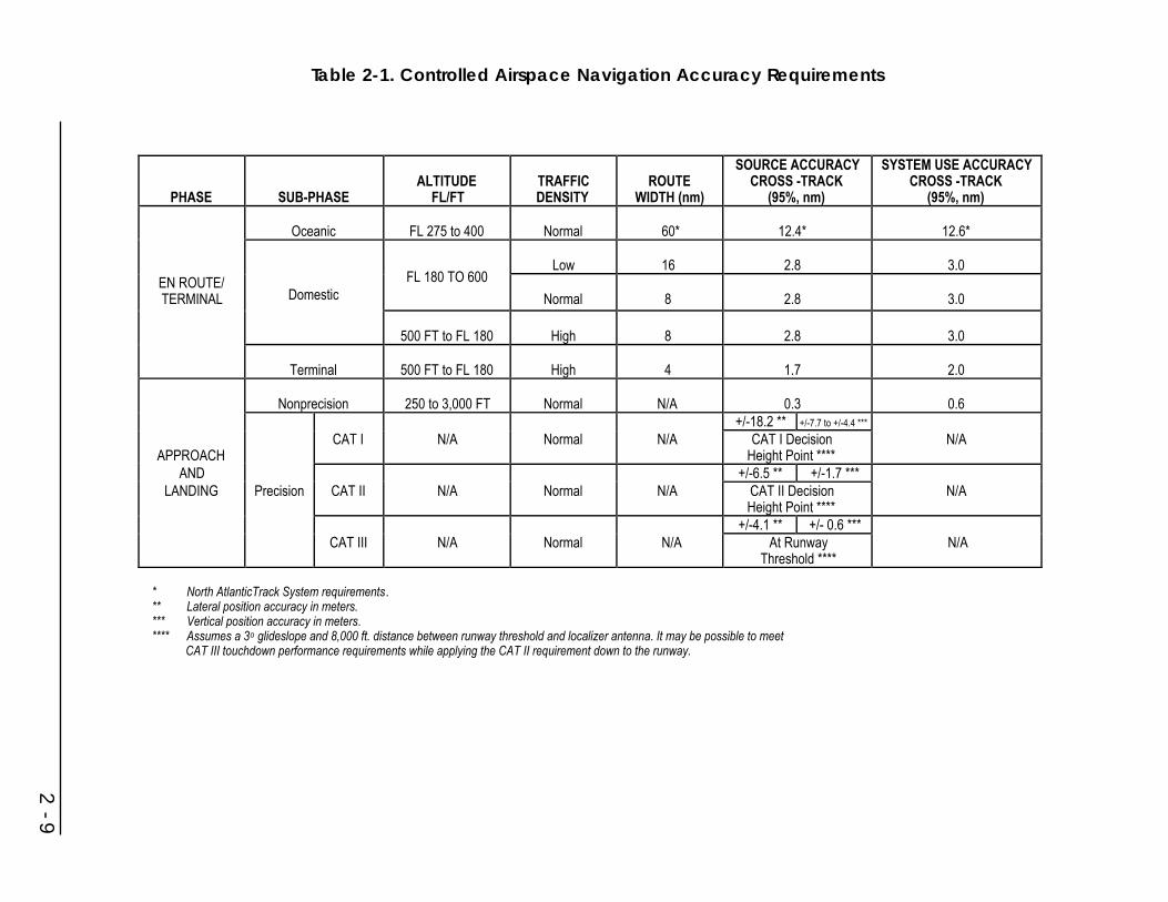
2 - 9
Table 2-1. Controlled Airspace Navigation Accuracy Requirements
PHASE SUB-PHASEALTITUDE
FL/FTTRAFFICDENSITY
ROUTEWIDTH (nm)
SOURCE ACCURACYCROSS -TRACK
(95%, nm)
SYSTEM USE ACCURACYCROSS -TRACK
(95%, nm)
Oceanic FL 275 to 400 Normal 60* 12.4* 12.6*
Low 16 2.8 3.0EN ROUTE/TERMINAL Domestic
FL 180 TO 600
Normal 8 2.8 3.0
500 FT to FL 180 High 8 2.8 3.0
Terminal 500 FT to FL 180 High 4 1.7 2.0
Nonprecision 250 to 3,000 FT Normal N/A 0.3 0.6+/-18.2 ** +/-7.7 to +/-4.4 ***
APPROACHCAT I N/A Normal N/A CAT I Decision
Height Point ****N/A
AND +/-6.5 ** +/-1.7 ***LANDING Precision CAT II N/A Normal N/A CAT II Decision
Height Point ****N/A
+/-4.1 ** +/- 0.6 ***CAT III N/A Normal N/A At Runway
Threshold ****N/A
* North AtlanticTrack System requirements.** Lateral position accuracy in meters.*** Vertical position accuracy in meters.**** Assumes a 3o glideslope and 8,000 ft. distance between runway threshold and localizer antenna. It may be possible to meet
CAT III touchdown performance requirements while applying the CAT II requirement down to the runway.
2.2.4.1.1 Oceanic En Route
The system must provide navigational capability commensurate with the need inspecific areas in order to permit safe navigation and the application of lateralseparation criteria. An organized track system has been implemented in the NorthAtlantic to gain the benefit of optimum meteorological conditions. Since anindependent surveillance system such as radar is not available, separation ismaintained by procedural means (e.g., position reports and timing).
The lateral separation standard on the North Atlantic organized track system is 60nm. The following system performance is required to achieve this separation:
1. The standard deviation of the lateral track errors shall be less than 6.3 nm, 1sigma (12.6 nm, 2 sigma).
2. The proportion of the total flight time spent by aircraft 30 nm or more off trackshall be less than 5.3 x 10⁻⁴; i.e., less than 1 hour in 2,000 flight hours.
3. The proportion of the total flight time spent by aircraft between 50 and 70 nmoff track shall be less than 1.3 x 10⁻⁴; i.e., approximately 1 hour in 8,000 flighthours.
Changes are being considered to reduce the route separation in parts of the PacificOcean to 50 nm. New performance requirements will be developed.
2.2.4.1.2 Domestic En Route
Domestic air routes are designed to provide airways that are as direct as practicalbetween city pairs having significant air traffic. For VOR-defined routes, via navaidsor radials, the protected airspace at FL 600 and below is 4 nm on each side of theroute to a point 51 nm from the navaid, then increases in width on either side of thecenterline at a 4.5 degree angle to a width of 10 nm on each side of the route at adistance of 130 nm from the navaid.
Current accuracy requirements for domestic en route navigation are based on thecharacteristics of the VOR/DME/VORTAC system and therefore relate to theangular characteristics of the VOR and TACAN azimuth systems and rangecharacteristics of the distance measuring equipment (DME)/TACAN range systems.“System Use Accuracy,” as defined by ICAO, is the RSS of the ground station errorcontribution, the airborne receiver error, the display system contribution, and theFlight Technical Error (FTE). FTE is the contribution of the pilot (or autopilot) inusing the presented information to control aircraft position. Error values on whichthe current system is based are as follows:
2 - 10
1. Azimuth Accuracy in Degrees:
2 SigmaDeviation
Error Component Values Source
VOR Ground 1.4o Semi-Automatic FlightInspection (SAFI) System
VOR Air +3.0o Equipment Manufacturer
Course Selection (CSE) +2.0o FAA Tests
Flight Technical (FTE) +2.3o FAA Tests
System Use Accuracy
(95% Confidence) +4.5o (RSS derived)
2. Range Accuracy
Where DME service is used, the system use accuracy is defined as +0.5 nm or 3percent of distance (2 sigma), whichever is greater. This value covers all existingDME avionics. When DME is used with an RNAV system, the range accuracy mustbe at least +0.2 nm plus 1 percent of the distance (2 sigma).
3. Area Navigation (RNAV)
RNAV computation equipment provides latitude and longitude coordinate navigationcapability. When RNAV equipment is used, an additional error contribution isspecified and combined in RSS fashion with the basic VOR/DME system error. Theadditional maximum RNAV equipment error allowed, per FAA Advisory CircularAC 90-45A (Ref. 2), is +0.5 nm. RNAV system performance and route design isbased on the following error budget:
2 SigmaDeviation
Error Component Values Source
VOR Ground +1.4o SAFI
VOR Air 3.0o Equipment Manufacturerand FAA Tests
DME Ground +0.1 nm SAFI
The VOR/DME and RNAV error values identified below result in 95 percent of theaircraft remaining within +4 nm of the airway centerline out to 51 nm from a VORfacility and within +4.5 degrees (originating at the VOR facility) of the airwaycenterline when beyond 51 nm from a VOR facility.
2 - 11

2 SigmaDeviation
Error Component Values Source
DME Air +0.2 nm Equipment Manufacturer*+ 1% of Range
FTE +1.0 nm FAA Tests**
CSE +2.0o FAA TestsRNAV System +0.5 nm Equipment Manufacturer
and FAA Tests
*Only DME aircraft equipment with this accuracy or better is used.**FTE -0.5 nm in the approach phase.
2.2.4.1.3 Terminal Area
Terminal routes provide transitions from the en route phase to the approach phase offlight. The accuracy capability of navigation systems using VOR/DME in terms ofbearing and distance to the facility is defined in the same manner as described for enroute navigation. However, the usually closer proximity to facilities provides greatereffective system use accuracy since both VOR and FTE are angular in nature and arerelated to the distance to the facility. The DME distance error is also reduced, sinceit is proportional to distance from the facility, down to the minimum error capability.Thus the system use accuracy requirement is +2 nm (95 percent) within 25 nm ofthe facility, based on the RSS the combination of error elements.
2.2.4.1.4 Remote Areas
Remote areas are defined as regions which do not meet the requirements forinstallation of VOR/DME service or where it is impractical to install this system.These include offshore areas, mountainous areas, and a large portion of the state ofAlaska. Thus the minimum route width varies and can be greater than +10 nm.
2.2.4.1.5 Operations Between Ground Level and 5,000 Feet Above GroundLevel (AGL)
Operations between ground level and 5,000 feet AGL occur in offshore,mountainous, and high-density metropolitan areas as well as on domestic routes. Foroperations from U.S. coastline to offshore points, the following requirements mustbe met:
• Range from shore to 300 nm.
• Minimum en route altitude of 500 feet above sea level or above obstructions.
• Accuracy adequate to support routes +4 nm wide or narrower with 95percent confidence.
2 - 12
• Minimum descent altitude to 100 feet in designated areas.
For helicopter operations over land, the following requirements must be met:
• Accuracy adequate to support +2 nm route widths in both en route andterminal areas with 95 percent confidence.
• Minimum en route altitudes of 1,200 feet AGL.
• Navigation signal coverage adequate to support approach procedures tominimums of 250 feet above obstruction altitudes at heliports and airports.
2.2.4.2 Approach/Landing Phase
This phase of instrument flight includes two types: (1) nonprecision approach, or (2)precision approach and landing.
The general requirements of Section 2.2.2 apply to the approach/landing phase. Inaddition, specific procedures and clearance zone requirements are specified inTERPS (United States Standard for Terminal Instrument Procedures, FAA Handbook8260.3B) (Ref. 3).
Altimetry accuracy requirements are established in accordance with FAR 91.411 andare the same as those for the en route/terminal phase.
The minimum performance criteria currently established to meet requirements forthe approach/landing phase of navigation vary between precision and nonprecisionapproaches.
2.2.4.2.1 Nonprecision Approach
Nonprecision approaches are based on any navigational system that meets thecriteria established in TERPS. Minimum safe altitude, obstacle clearance area,visibility minimum, final approach segment area, etc., are all functions of thenavigational accuracy available and other factors. The unique features of RNAV fornonprecision approaches are specified in Reference 4.
The achieved capability for nonprecision approaches varies significantly, dependingon the location of the navigational facility in relation to the fix location and type ofnavigational system used. Approximately 30 percent of the nonprecision approachfixes based on VOR in the U.S. achieve a cross track navigational accuracy of +100meters (2 sigma) at the missed approach point (MAP). This accuracy is based uponthe +4.5 degrees VOR system use accuracy and the MAP being less than 0.7 nmfrom the VOR facility.
Nonprecision RNAV approaches must satisfy their own criteria and are based on theobstacle clearance areas shown in Figure 2-1. The width of the intermediateapproach trapezoid primary areas decreases from 4 nm (2 nm each side of the routecenterline) at the end of the intermediate fix or waypoint displacement area to 2 nm
2 - 13

(1 nm each side of the route centerline) at the final approach fix or waypoint.Primary obstacle clearance areas further narrow to the width of the runway waypointfix displacement area at its furthest point. Secondary areas (not depicted) also extendupward and outward from the sides of the primary area.
The integrity time-to-alarm requirement for nonprecision approaches provides thepilot with either a warning or a removal of signal within 10 seconds of theoccurrence of an out-of-tolerance condition.
Figure 2-1. RNAV Nonprecision Approach Protected Areas
2.2.4.2.2 Precision Approach and Landing
A precision approach and landing aid provides a landing aircraft with vertical andhorizontal guidance and position information. The current worldwide standardsystems for precision approach and landing are the Instrument Landing System(ILS) and the Microwave Landing System (MLS). International agreements havebeen made to achieve an all-weather landing capability through an evolutionaryprocess, reducing landing weather minima on a step-by-step basis as technicalcapabilities and operational knowledge permit. The performance objectives for thevarious landing categories are shown in Table 2-1.
Precision approach and landing systems are required to warn the pilot of an out-of-tolerance condition during precision approaches by removing these signals fromservice. The response time for providing these warnings varies from six seconds forCategory I to two seconds for Category II/III.
2.2.5 Future Aviation Navigation Requirements
Future aviation navigation requirements will be based on new criteria using theconcept of required navigation performance (RNP). This concept is being developedsuch that unified criteria will be established for airworthiness approval, ground
2 - 14
IF Waypoint
2 nm
1 nm
FAF WaypointRWY Waypoint
Displacement Area
0.5 nm
Fix Displacement Areas

equipment approval (if required), operating approval, establishment of operatingminima and obstacle clearance assessment.
Altimetry requirements for vertical separation of 1,000 feet, below FL 290, are notexpected to change. Increased altimetry accuracy is needed at and above FL 290 topermit separation less than the current standard of 2,000 feet. The required future 3sigma value of the aircraft altimetry system error has not been specified, but it mustbe accurate enough to support the introduction of 1,000-foot vertical separation at allflight levels.
2.2.5.1 En Route/Terminal Phase
2.2.5.1.1 Oceanic En Route
Current separation specifications have been designed to allow a lateral separation of60 nm. This was put into effect for certain areas of the North Atlantic in early 1981and requires a lateral track error less than 12.6 nm (95 percent). More accurate andreliable aircraft position data will greatly contribute to reductions in lateralseparation, resulting in greater flexibility and the ability to fly user-preferred routes.Efforts are under way to reduce some route separations in the Pacific area to 50 nm.The navigation requirements for this are being developed.
2.2.5.1.2 Domestic En Route
At the present time, the number of VOR/DMEs is sufficient to allow most routes tohave widths of +4 nm. This is possible as most VOR facilities are spaced less than100 nm apart on the route. However, greater spacings are used in low traffic densityareas, remote areas, and on most of the high-altitude route structure. Parts of thehigh-altitude route structure have a distance between VOR facilities resulting inroute widths up to 20 nm.
Traffic increases may soon exceed capacity. More use of RNAV will allow theimplementation of random and parallel routes not possible with the use of currentVOR/DME facilities, thus easing the capacity problem. No increase in VOR/DMEground accuracy is required to meet the navigational requirements imposed by theair traffic levels estimated for the year 2000.
2.2.5.1.3 Terminal Area
The major change forecasted for the terminal area is the increased use of RNAV andtime control to achieve optimum runway utilization and noise abatement procedures.Some current multi-DME RNAV avionics can provide cross track navigationalaccuracies better than +500 meters (2 sigma) in terminal areas using the currentVOR/DME facilities. Similarly, GPS-based avionics deliver better accuracies andperformance than VOR/DME.
2 - 15

2.2.5.1.4 Remote Areas
Many areas, such as Alaska, the Rocky Mountains and other mountainous areas, andsome offshore locations, cannot be served easily or at all by VOR/DME. Presently,nondirectional beacons (NDB), Omega, and privately owned facilities such asTACAN are being used in combination to meet the user navigational needs in theseareas. GPS, Omega and Loran-C are being used as supplements to VOR/DME tomeet these needs. The accuracy and coverage of these systems seem adequate tohandle the traffic densities projected for the different areas.
2.2.5.2 Approach/Landing Phase
2.2.5.2.1 Nonprecision Approach
Nonprecision approach obstacle clearance areas may be reduced to take advantageof the increased performance by augmented GPS.
2.2.5.2.2 Precision Approach and Landing
Future requirements for precision approaches will be developed for specific systemsusing the RNP concept. The RNP concept provides a framework to driverequirements based on the need to avoid obstacles and place the aircraft in a positionto land.
2.3 Civil Marine Radionavigation Requirements
2.3.1 Phases of Marine Navigation
Marine navigation in the U.S. consists of four major phases identified as inlandwaterway, harbor entrance and approach, coastal, and ocean navigation. Standards orrequirements for safety of navigation and reasonable economic efficiency can bedeveloped around these four phases. Specialized requirements, which may begenerated by the specific activity of a ship, must be addressed separately.
2.3.1.1 Inland Waterway
Inland waterway navigation is conducted in restricted areas similar to those forharbor entrance and approach. However, in the inland waterway case, the focus is onnonseagoing ships and their requirements on long voyages in restricted waterways,typified by tows and barges in the U.S. Western Rivers System and the U.S.Intracoastal Waterway System.
In some areas, seagoing craft in the harbor phase of navigation and inland craft inthe inland waterway phase share the use of the same restricted waterway. Thedistinction between the two phases depends primarily on the type of craft. It is madebecause seagoing ships and typical craft used in inland commerce have differencesin physical characteristics, personnel, and equipment. These differences have a
2 - 16

significant impact upon their requirements for aids to navigation. Recreational andother relatively small craft are found in large numbers in waters used by bothseagoing and inland commercial traffic and generally have less rigid requirements ineither case.
2.3.1.2 Harbor Entrance and Approach
Harbor entrance and approach navigation is conducted in waters inland from thoseof the coastal phase. For a ship entering from the sea or the open waters of the GreatLakes, the harbor approach phase begins generally with a transition zone betweenthe relatively unrestricted waters where the navigational requirements of coastalnavigation apply, and narrowly restricted waters near and/or within the entrance to abay, river, or harbor, where the navigator enters the harbor phase of navigation.Usually, harbor entrance requires navigation of a well-defined channel which, at theseaward end, is typically from 180 to 600 meters in width if it is used by large ships,but may narrow to as little as 120 meters farther inland. Channels used by smallercraft may be as narrow as 30 meters.
From the viewpoint of establishing standards or requirements for safety ofnavigation and promotion of economic efficiency, there is some genericcommonality in harbor entrance and approach. In each case, the nature of thewaterway, the physical characteristics of the vessel, the need for frequentmaneuvering of the vessel to avoid collision, and the closer proximity to groundingdanger impose more stringent requirements for accuracy and for real-time guidanceinformation than for the coastal phase.
For analytical purposes, the phase of harbor entrance and approach is built aroundthe problems of precise navigation of large seagoing and Great Lakes ships innarrow channels between the transition zone and the intended mooring.
2.3.1.3 Coastal Navigation
Coastal navigation is that phase in which a ship is within 50 nm from shore or thelimit of the continental shelf (200 meters in depth), whichever is greater, where asafe path of water at least one mile wide, if a one-way path, or two miles wide, if atwo-way path, is available. In this phase, a ship is in waters contiguous to major landmasses or island groups where transoceanic traffic patterns tend to converge inapproaching destination areas; where interport traffic exists in patterns that areessentially parallel to coastlines; and within which ships of lesser range usuallyconfine their operations. Traffic-routing systems and scientific or industrial activityon the continental shelf are encountered frequently in this phase of navigation. Shipson the open waters of the Great Lakes also are considered to be in the coastal phaseof navigation.
The boundary between coastal and ocean navigation is defined by one of thefollowing which is farthest from land:
2 - 17
• 50 nautical miles from land.
• The outer limit of offshore shoals, or other hazards on the continental shelf.
• Other waters where traffic separation schemes have been established, andwhere requirements for the accuracy of navigation are thereby made morerigid than the safety requirements for ocean navigation.
2.3.1.4 Ocean Navigation
Ocean navigation is that phase in which a ship is beyond the continental shelf (200meters in depth), and more than 50 nm from land, in waters where position fixing byvisual reference to land or to fixed or floating aids to navigation is not practical.Ocean navigation is sufficiently far from land masses so that the hazards of shallowwater and of collision are comparatively small.
2.3.2 Current Marine Navigation Requirements
The navigational requirements of a vessel depend upon its general type and size, theactivity in which the ship is engaged (e.g., point-to-point transit, fishing) and thegeographic region in which it operates (e.g., ocean, coastal), as well as other factors.Safety requirements for navigation performance are dictated by the physicalconstraints imposed by the environment and the vessel, and the need to avoid thehazards of collision, ramming, and grounding.
The above discussion of phases of marine navigation sets the framework fordefining safety of navigation requirements. However, the economic and operationaldimensions also need to be considered for the wide diversity of vessels that traversethe oceans and U.S. waters. For example, navigation accuracy (beyond that neededfor safety) is particularly important to the economy of large seagoing ships havinghigh hourly operating costs. For fishing and oil exploration vessels, the ability tolocate precisely and return to productive or promising areas and at the same timeavoid underwater obstructions or restricted areas provides important economicbenefits. Search and Rescue (SAR) effectiveness is similarly dependent on accuratenavigation in the vicinity of a maritime distress incident.
For system planning, the Government seeks to satisfy minimum safety requirementsfor each phase of navigation and to maximize the economic utility of the service forusers. Since the vast majority of marine users are required to carry only minimalnavigational equipment, and even then do so only if persuaded by individualcost/benefit analysis, this governmental policy helps to promote maritime safetythrough a simultaneous economic incentive.
Tables 2-2, 2-3, 2-4, and 2-5 identify system performance needed to satisfy maritimeuser requirements or to achieve special benefits. The requirements are related tosafety of navigation. The Government recognizes an obligation to satisfy theserequirements for the overall national interest. The benefits are specializedrequirements or characteristics needed to provide special benefits to discrete classes
2 - 18

2 - 19
Table 2-2. Current Maritime User Requirements for Purposes of System Planning and Development - InlandWaterway Phase
MEASURES OF MINIMUM PERFORMANCE CRITERIA TO MEET REQUIREMENTS
REQUIREMENTS ACCURACY(meters, 2drms) COVERAGE AVAILABILITY RELIABILITY
FIXINTERVAL
FIXDIMENSIONS
SYSTEMCAPACITY AMBIGUITY
PREDICTABLE REPEATABLESAFETY OF NAVIGATION
ALL SHIPS & TOWS
2-5 2-5US InlandWaterwaySystems
99.9% * 1-2 seconds Two UnlimitedResolvablewith 99.9%confidence
SAFETY OF NAVIGATION
RECREATION BOATS & SMALLER VESSELS
5-10 5-10US InlandWaterwaySystems
99.9% * 5-10 seconds Two UnlimitedResolvablewith 99.9%confidence
RIVER ENGINEERING& CONSTRUCTIONVESSELS
0.1**-5 0.1**-5US InlandWaterwaySystems
99% * 1-2 seconds Two or Three UnlimitedResolvablewith 99.9%confidence
* Dependant upon mission time** Vertical dimension
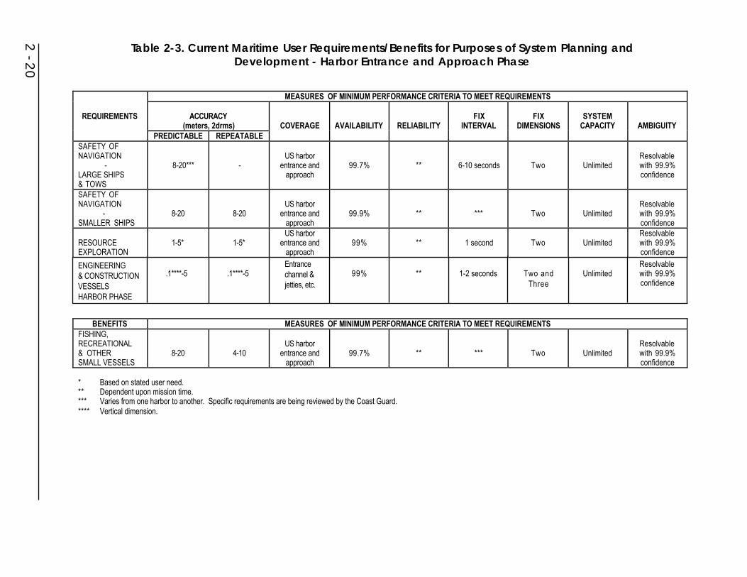
2 - 20
Table 2-3. Current Maritime User Requirements/Benefits for Purposes of System Planning andDevelopment - Harbor Entrance and Approach Phase
MEASURES OF MINIMUM PERFORMANCE CRITERIA TO MEET REQUIREMENTS
REQUIREMENTS ACCURACY(meters, 2drms) COVERAGE AVAILABILITY RELIABILITY
FIXINTERVAL
FIXDIMENSIONS
SYSTEMCAPACITY AMBIGUITY
PREDICTABLE REPEATABLESAFETY OFNAVIGATION
-LARGE SHIPS& TOWS
8-20*** -US harbor
entrance andapproach
99.7% ** 6-10 seconds Two UnlimitedResolvablewith 99.9%confidence
SAFETY OFNAVIGATION
-SMALLER SHIPS
8-20 8-20US harbor
entrance andapproach
99.9% ** *** Two UnlimitedResolvablewith 99.9%confidence
RESOURCEEXPLORATION
1-5* 1-5*US harbor
entrance andapproach
99% ** 1 second Two UnlimitedResolvablewith 99.9%confidence
BENEFITS MEASURES OF MINIMUM PERFORMANCE CRITERIA TO MEET REQUIREMENTSFISHING,RECREATIONAL& OTHERSMALL VESSELS
8-20 4-10US harbor
entrance andapproach
99.7% ** *** Two UnlimitedResolvablewith 99.9%confidence
* Based on stated user need.** Dependent upon mission time.*** Varies from one harbor to another. Specific requirements are being reviewed by the Coast Guard.**** Vertical dimension.
ENGINEERING& CONSTRUCTIONVESSELSHARBOR PHASE
.1****-5 .1****-5Entrancechannel & jetties, etc.
99% ** 1-2 seconds Two andThree
UnlimitedResolvablewith 99.9%confidence

2 - 21
Table 2-4. Current Maritime User Requirements/Benefits for Purposes of System Planning and Development -Coastal Phase
MEASURES OF MINIMUM PERFORMANCE CRITERIA TO MEET REQUIREMENTS
REQUIREMENTS ACCURACY(meters, 2drms) COVERAGE AVAILABILITY RELIABILITY
FIXINTERVAL
FIXDIMENSIONS
SYSTEMCAPACITY AMBIGUITY
PREDICTABLE REPEATABLESAFETY OFNAVIGATION
-ALL SHIPS
0.25nm(460m) -
US coastalwaters 99.7% ** 2 minutes Two Unlimited
Resolvablewith 99.9%confidence
SAFETY OFNAVIGATION
-RECREATIONBOATS & OTHERSMALLERVESSELS
0.25nm-2nm(460-3,700m) -
US coastalwaters 99. ** 5 minutes Two Unlimited
Resolvablewith 99.9%confidence
BENEFITS MEASURES OF MINIMUM PERFORMANCE CRITERIA TO MEET REQUIREMENTSCOMMERCIALFISHING(INCLUDINGCOMMERCIALSPORT FISHING)
0.25nm(460m)
50-600 ft(15-180m)
US coastal/fisheries areas 99% ** 1 minute Two Unlimited
RESOURCEEXPLORATION 1.0-100m* 1.0-100m*
US coastalareas 99% ** 1 second Two Unlimited
SEARCHOPERATIONS,LAWENFORCEMENT
0.25nm(460m)
300-600 ft(90-180m)
US coastal/fisheries areas 99.7% ** 1 minute Two Unlimited
RECREATIONALSPORTS FISHING
0.25nm(460m)
100-600 ft(30-180m)
US coastalareas 99% ** 5 minutes Two Unlimited
Resolvablewith 99.9%confidence
* Based on stated user need.** Dependent upon mission time.

2 - 22
Table 2-5. Current Maritime User Requirements/Benefits for Purposes of System Planning and Development -Ocean Phase
MEASURES OF MINIMUM PERFORMANCE CRITERIA TO MEET REQUIREMENTS
REQUIREMENTS ACCURACY(2 drms) COVERAGE AVAILABILITY RELIABILITY
FIXINTERVAL
FIXDIMENSION
SYSTEMCAPACITY AMBIGUITY
PREDICTABLE REPEATABLE RELATIVE
SAFETY OFNAVIGATION
-ALL CRAFT
2-4nm(3.7-7.4km)minimum1-2nm
(1.8-3.7km)desirable
- - Worldwide99% fix at leastevery 12 hours **
15 minutes orless desired;
2 hoursmaximum
Two Unlimited
Resolvablewith 99.9%confidence
BENEFITS MEASURES OF MINIMUM PERFORMANCE CRITERIA TO MEET REQUIREMENTSLARGE SHIPSMAXIMUMEFFICIENCY
0.1-0.25nm*(185-460m)
- -Worldwide,except polar
regions99% ** 5 minutes Two Unlimited
Resolvablewith 99.9%confidence
RESOURCEEXPLORATION
10-100m* 10-100m* - Worldwide 99% ** 1 minute Two UnlimitedResolvablewith 99.9%confidence
SEARCHOPERATIONS
0.1-0.25nm(185-460m)
0.25nm 0.1nm(185m)
Nationalmaritime SAR
regions99% ** 1 minute Two Unlimited
Resolvablewith 99.9%confidence
* Based on stated user need.** Dependent upon mission time.

of maritime users (and additional public benefits which may accrue from servicesprovided by users). The Government does not recognize an absolute commitment tosatisfy these requirements, but does endeavor to meet them if their cost can bejustified by benefits which are in the national interest. For the purpose of comparingthe performance of systems, the requirements are categorized in terms of systemperformance characteristics representing the minimum performance considerednecessary to satisfy the requirements or achieve special benefits.
2.3.2.1 Inland Waterway Phase
Very large amounts of commerce move on the U.S. inland waterway system, muchof it in slow-moving, comparatively low-powered tug and barge combinations. Towson the inland waterways, although comparatively shallow in draft, may be longerand wider than large seagoing ships which call at U.S. ports. Navigable channelsused by this inland traffic are often narrower than the harbor access channels usedby large ships. Restricted visibility and ice cover present problems in inlandwaterway navigation, as they do in harbor entrance and approach navigation. Thelong, ribbon-like nature of the typical inland waterway presents special problems tothe prospective user of precise, land-based area navigation systems. Continualshifting of navigable channels in some unstable waters creates additional problemsto the prospective user of any radionavigation system which provides positionmeasurements in a fixed coordinate system.
Special waterways, such as the Saint Lawrence River and some Great Lakespassages, are well defined, but subject to frequent fog cover which requires ships toanchor. This imposes a severe economic penalty in addition to the safety issues. If afog rolls in unexpectedly, a ship may need to proceed under hazardous conditions toan anchorage clear of the channel or risk stopping in a channel. Currentrequirements for the inland waterway phase of navigation are provided in Table 2-2.
2.3.2.2 Harbor Entrance and Approach Phase
The pilot of a vessel in restricted waters must direct its movement with greataccuracy and precision to avoid grounding in shallow water, hittingsubmerged/partially submerged rocks, and colliding with other craft in congestedwaterways. Unable to turn around, and severely limited in the ability to stop toresolve a navigational problem, the pilot of a large vessel (or a tow boat and bargecombination) may find it necessary to hold the total error in navigation within limitsmeasured in a few feet while navigating in this environment. It would appear that amajor step in maximizing the effectiveness of radionavigation systems in the harborentrance and approach environment is to present the position information on someform of electronic display. This would provide a ship’s captain, pilot, or navigator acontinual reference, as opposed to plotting “outdated” fixes on a chart to show therecent past. It is also recognized that the role of the existing radionavigation systemdecreases in this harbor entrance and approach environment, while the role of visualaids and radar escalates.
2 - 23
Requirements: To navigate safely, the pilot needs highly accurate verification ofposition almost continuously, together with information depicting any tendency forthe vessel to deviate from its intended track and a nearly continuous andinstantaneous indication of the direction in which the pilot should steer. Table 2-3was developed to present estimates of these requirements. To effectively utilize therequirements stated in the table, however, a user must be able to relate the data toimmediate positioning needs. This is not practical if one attempts to plot fixes on achart in the traditional way. To utilize radionavigation information that is presentedat less than 10-second intervals on a moving vessel, some form of an automaticdisplay is required. Technology is available which presents radionavigationinformation along with other data.
Minimum Performance Criteria: The radionavigation system accuracy required toprovide useful information in the harbor entrance and approach phase of marinenavigation varies from harbor to harbor, as well as with the size of the vessel. In themore restricted channels, accuracy in the range of 8 to 20 meters (2 drms) may berequired for the largest vessels. A need exists to more accurately determine theseradionavigation requirements for various-sized vessels while operating in suchrestricted confines. Radionavigation user conferences have indicated that for manymariners, the radionavigation system becomes a secondary tool when entering theharbor entrance and approach environment.
Continuing efforts are being directed toward verifying user requirements and desiresfor radionavigation systems in the harbor entrance and approach environment.
2.3.2.3 Coastal Phase
There is a need for continuous, all-weather radionavigation service in the coastalarea to provide, at the least, the position fixing accuracy to satisfy minimum safetyrequirements for general navigation. These requirements are delineated in Table 2-4.Furthermore, the total navigational service in the coastal area must provide serviceof useful quality and be within the economic reach of all classes of mariners. Itshould be sufficient to assure that no boat or ship need be lost or endangered, or thatthe environment and public safety not be threatened, because a vessel could notnavigate safely with reasonable economic efficiency.
Requirements: Requirements on the accuracy of position fixing for safety purposesin the coastal phase are established by:
• The need for larger vessels to navigate within the designated one-way trafficlanes at the approaches to many major ports, in fairways established throughoffshore oil fields, and at safe distances from shallow water.
• The need to define accurately, for purposes of observing and enforcing U.S.laws and international agreements, the boundaries of the FisheryConservation Zone, the U.S. Customs Zone, and the territorial waters of theU.S.
2 - 24
Minimum Performance Criteria: Government studies have established that anavigation system providing a capability to fix position to an accuracy of 0.25 nmwill satisfy the minimum safety requirements if a fix can be obtained at least every15 minutes. As a secondary economic factor, it is required that relatively higherrepeatable accuracy be recognized as a major advantage in the consideration ofalternative candidate radionavigation systems for the coastal area. As indicated inTable 2-4, these requirements may be relaxed slightly for the recreational boatersand other small vessels.
In such activities as marine scientific research, hydrographic surveying, commercialfishing, and petroleum or mineral exploration, as well as in Navy operations, theremay be a need to establish position in the coastal area with much higher accuracythan that needed for safety of general navigation. In many of these special operationswhich require highly accurate positions, the use of radiodetermination would beclassified as radiolocation rather than radionavigation. As shown in Table 2-4, themost rigid requirement of any of this general group of special operations is forseismic surveying with a repeatable accuracy on the order of 1 to 100 meters (2drms), and a fix rate of once per second for most applications.
2.3.2.4 Ocean Phase
The requirements for safety of navigation in the ocean phase for all ships are givenin Table 2-5. These requirements must provide the Master with a capability to avoidhazards in the ocean (e.g., small islands, reefs) and to plan correctly the approach toland or restricted waters. For many operational purposes, repeatability is necessaryto locate and return safely to the vicinity of a maritime distress, as well as for specialactivities such as hydrography, research, etc. Economic efficiency in safe transit ofopen ocean areas depends upon the continuous availability of accurate position fixesto enable the vessel to follow the shortest safe route with precision, minimizingtransit time.
Requirements: For safe general navigation under normal circumstances, therequirements for the accuracy and frequency of position fixing on the high seas arenot very strict. As a minimum, these requirements include a predictable accuracy of2 to 4 nm coupled with a maximum fix interval of 2 hours or less. These minimumrequirements would permit reasonably safe oceanic navigation, provided that thenavigator understands and makes allowances for the probable error in navigation,and provided that more accurate navigational service is available as land isapproached. While these minimum requirements would permit all vessels to navigatewith relative safety on the high seas, more desirable requirements would bepredictable accuracy of 1 to 2 nm and a fix interval of 15 minutes or less. Thenavigation signal should be available 95 percent of the time. Further, in any 12-hourperiod, the probability of obtaining a fix from the system should be at least 99percent.
Larger recreational craft and smaller commercial fishing vessels which sail beyondthe range of coastal navigation systems require, for a reasonable level of safety,
2 - 25
some means of establishing their position reliably at intervals of a few hours at most.Even more so than with larger ships, this capability is particularly important in timeof emergency or distress. Many operators of these craft, however, will accept therisk of ocean sailing without reliable radionavigation unless that capability isavailable at relatively low cost.
Minimum Performance Criteria: Economic efficiency in transoceanic transportation,special maritime activities and safety in emergency situations require or benefit fromnavigational accuracy higher than that needed for safety in routine, point-to-pointocean voyages. These requirements are summarized in Table 2-5. The predictableaccuracy benefits may be as stringent as 10 meters for special maritime activities,and may range to 0.25 nm for large, economically efficient vessels, including searchoperations. Search operations must also have a repeatable accuracy of at least 0.25nm. As indicated in Table 2-5, the required fix interval may range from as low asonce per 5 minutes to as high as once per minute. Signal availability must be at least95 percent and approach 99 percent for all users.
2.3.3 Future Marine Navigation Requirements
The marine radionavigation requirements presented in the preceding discussions andtables are based on a combination of requirements studies, user inputs, andestimates. However, they are the product of current technology and operatingpractices, and are therefore subject to revision as technologies and operatingtechniques evolve. The principal factors which will impact future requirements aresafety, economics, environment, and energy conservation.
Special radionavigation requirements may arise from new environmental laws andregulations designed to reduce marine vessel casualty events. Also, the role ofcommercial ships in military sealift missions may require additional navigationsystems capabilities.
2.3.3.1 Safety
2.3.3.1.1 Increased Risk from Collision and Grounding
Hazardous cargoes (petroleum, chemicals, etc.) are carried in great volumes in U.S.coastal and inland waterways. Additionally, the ever increasing volume of othershipping and the increasing numbers of smaller vessels act to constantly increase therisk of collision and grounding. Economic constraints also cause vessels to beoperated in a manner which, although not unsafe, places more stringent demands onall navigation systems.
2.3.3.1.2 Increased Size and Decreased Maneuverability of Marine Vessels
The desire to minimize costs and to capture economies of scale in marinetransportation have led to design and construction of larger vessels and unitized
2 - 26

tug/barge combinations, both of which are relatively less powerful andmaneuverable than their predecessors. Consequently, improved navigationalperformance is needed.
2.3.3.1.3 Greater Need for Traffic Management/Navigational SurveillanceIntegration
The foregoing trends underlie the importance of continued governmentalinvolvement in marine vessel traffic management to assure reasonable safety in U.S.waters. Radionavigation systems may become an essential component of trafficmanagement systems. Differential GPS is expected to play an increasingly importantrole in such areas as VTS.
2.3.3.2 Economics
2.3.3.2.1 Greater Congestion in Inland Waterways and Harbor Entrances andApproaches
In addition to the safety penalty implicit in greater congestion in restrictedwaterways, there are economic disadvantages if shore facilities are not usedeffectively and efficiently. Accurate radionavigation systems can contribute to betterproductivity and decreased delay in transit.
2.3.3.2.2 All Weather Operations
Low visibility and ice-covered waters presently impede full use of the marinetransportation mode. Evolving radionavigation systems may eventually alleviate theimpact of these restrictions.
2.3.3.3 Environment
As onshore energy supplies are depleted, resource exploration and exploitation willmove farther offshore toward the U.S. outer continental shelf and to harsher andmore technically demanding environments. In addition, more intensive U.S. fishingactivity is anticipated as the result of legislative initiatives and the creation of theU.S. Fishery Conservation Zone. In summary, both sets of activities may generatedemands for navigational services of higher quality and for broadened geographiccoverage in order to allow environmentally sound development of resources.
2.3.3.4 Energy Conservation
The need to conserve energy resources and to reduce costs provides powerfulincentives for increased transportation efficiency, some of which could come frombetter navigation systems.
2 - 27

2.4 Space Radionavigation Requirements
2.4.1 Mission Phases
For Earth-orbiting space activities, the mission phases can be generally categorizedas the ground launch phase, the on-orbit phase, and the reentry and landing phase. Inaddition to the government sponsored space activities coordinated by NASA, there isa growing U.S. commercial space transportation industry seeking to launch bothgovernment and private payloads. There is also a growing private sector presence inspace commerce that reflects sizable investments in such emerging uses as materialsprocessing, land mobile services, radiodetermination, and remote sensing.
2.4.1.1 Ground Launch Phase
This phase is defined as that portion of the mission from the point at which a vehicleleaves the launch pad to the point wherein the vehicle inserts the payload into Earthorbit.
2.4.1.2 On-Orbit Phase
This is the phase wherein key operations or data gathering from an experiment tomeet the primary mission objectives is performed. During this phase, the launchvehicle may deploy a satellite or perform positional maneuvers in support ofonboard experiments. Vehicles capable of reentry may also retrieve a satellite forreturn to Earth. This phase essentially ends when the vehicle has completed itsmission or initiates de-orbit maneuvers. In this phase, free-flying spacecraft performtheir experiments and operations in their required orbits. In those cases where thespacecraft will not be returned to Earth, this operational phase continues until suchtime as the spacecraft is shut down or can no longer perform its functions. For thosespacecraft to be returned to Earth, this phase essentially ends when the spacecraft iseither retrieved by a reentry vehicle or returns to Earth on its own.
2.4.1.3 Reentry and Landing Phase
This phase begins when a reentry vehicle, possibly with onboard experiments or aretrieved spacecraft, initiates de-orbit maneuvers. The vehicle goes throughatmospheric entry and makes an unpowered landing. This phase ends when thevehicle comes to a full stop.
2.4.2 Current Space Radionavigation Requirements
The use of GPS for space applications fall into two basic categories:
1. Onboard spacecraft vehicle navigation support where GPS and GPSaugmentations will be used in near real-time applications for navigation andattitude determination. In this role, onboard navigation and attitude accuracyrequirements are:
2 - 28
• Three-dimensional position error not to exceed 10 cm (1 sigma).
• Three-dimensional velocity error not to exceed 0.1 m/sec (1 sigma).
• Attitude determination error not to exceed 0.1 degree in each axis (1 sigma).
• Clock offset error between coordinated universal time (UTC) and onboardreceiver time not to exceed 1 microsecond (1 sigma).
2. Scientific data analysis support where GPS will be used in a post-processingmode to accurately locate instrument position in space when measurements aretaken. Current accuracy requirements are to determine three dimensional positionwithin 5 cm. However, more accurate positioning in the 1 to 2 cm range may berequired in the future for some earth observation instruments. Several programsconducted or supported by NASA are evaluating GPS for spacecraft positiondetermination. TOPEX/POSEIDON, launched on August 10, 1992, is using ahigh-accuracy dual-band GPS flight receiver on an experimental basis. Based onsuccessful experiments conducted on the Space Shuttle and on theTOPEX/POSEIDON and EUVE instrumented satellites, NASA is planning toimplement GPS as an operational system on many future missions including theSpace Shuttle and International Space Station Alpha (ISSA).
Planned and proposed future NASA spacecraft will require continued use of GPS.Examples of GPS applications include the following:
• ISSA is being designed to implement GPS for navigation, attitudedetermination, and Universal Time distribution. GPS will support onboardISSA system control functions as well as various experimenter data captureprocesses.
• The Space Shuttle will implement GPS for the on-orbit and reentry andlanding mission phases by 2000. Also, research will be conducted in the useof GPS during the Space Shuttle’s ground launch phase.
• New small satellite programs to explore low cost access to space willimplement GPS for navigation, time, and attitude determination functions.The use of low cost onboard GPS receivers for these basic functions willbecome a significant factor in providing inexpensive access to space forfuture NASA and commercial small satellite projects.
• Where scientific data position accuracy is required with precision greaterthan that readily available from the GPS receiver onboard a spacecraft, arefinement of post-pass orbit data will be used. NASA has developed post-pass orbit data processing techniques using GPS on the TOPEX/POSEIDONsatellite that provide accuracy at the 5 cm level. In order to accomplish this,some internal receiver parameters must be available for downlink with thescience data.
• In addition to use of GPS for scientific data positioning in a post processingmode, NASA is investigating the use of WAAS and eventually GNSS for real
2 - 29

time position information. Current research indicates that real time accuracyat the 10 cm level may be achievable.
• GPS tracking is being used by the NASA Deep Space Network (DSN) toimprove knowledge of the Earth’s pole position and speed of rotation. Theuse of GPS for this purpose is making a significant reduction in demand formeasurements with deep space antennas, thus realizing cost savings. Thecentimeter level accuracy available with GPS tracking for geocentriccorrection to deep-space antenna coordinates is significantly improving thedeep-space tracking error budget.
• The use of GPS at satellite altitudes extending from low earth orbit (LEO)out to geosynchronous earth orbit (GEO) altitudes will be explored by NASAin conjunction with other organizations.
• Potentially, GPS will be a primary real-time position information source forlaunch vehicles including the new returnable launch vehicle.
2.5 Civil Land Radionavigation Requirements
In comparison with the air and marine communities, phases of land navigation arenot well defined. Radionavigation requirements are more easily categorized in termsof applications. The land navigation applications fall into three basic categories;highway, transit, and rail applications. Ongoing work on Intelligent TransportationSystems (ITS), which includes research and development (R&D) and operationaltest programs funded by the Department of Transportation’s modal administrations(including FHWA, FTA, and NHTSA) as well as by State and local governments andprivate industry, will aid in clarifying and validating user requirements.
2.5.1 Categories of Land Transportation
2.5.1.1 Highways
Radionavigation techniques in highway applications are used autonomously or areintegrated with vehicle-to-roadside communications and map-matching techniques toprovide various user services. These are public sector operational tests ongoing forintegrated ITS systems, where radionavigation is a part of the system. However, anumber of consumer products and products for use by the public sector are on themarket today. Deployment of these systems is accelerating at a rapid pace. Vehiclelocation systems for emergency service, providers of mayday services, routenavigation for private automobiles, and tracking and scheduling of commercialvehicles are in use. Examples of systems in development include augmentation ofGPS vehicle location data by providing DGPS correction values over wirelesscommunications. Also under development is a system for vehicle locationmonitoring using GPS integrated with wireless packet data systems. Examples ofsystems used in operational tests for ITS funded by FHWA include the use ofradionavigation for automatic vehicle location for mayday response, route guidance,
2 - 30

mass transit scheduling, and mileage determination. Examples of systems that arefielded and operational include radionavigation for dispatching roadside assistancevehicles and automated location tracking and scheduling of commercial vehicles. Inaddition to these examples, radionavigation is used by various highway departmentsfor asset management by using GPS coordinates to identify locations of bridges,highway signs, and overpasses. Table 2-6 shows examples of ITS user servicesrequiring the use of radionavigation. A complete description of all of the ITS userservices can be found in ITS System Architecture documentation (Ref. 5).
2.5.1.2 Transit
Transit systems also benefit from the same radionavigation-based technologies.Automatic vehicle location techniques assist in fleet management, scheduling, real-time customer information, and emergency assistance. In addition, random routetransit operations will benefit from route guidance in rural and low density areas.Also, services such as automated transit stop annunciation are being investigated.Benefits of radiolocation for public transit, when implemented with a two-waycommunications system, have been proven in a number of deployments across theU.S. Improvements in on-time performance, efficiency of fleet utilization, andresponse to emergencies have all been documented. Currently, there are over 10,000
2 - 31
Travel and Transportation ManagementPre-Trip Travel InformationEn Route Driver InformationRoute GuidanceIncident ManagementTravel Demand Management
Public Transportation OperationsPublic Transportation ManagementPersonalized Public Transportation
Commercial Vehicle OperationsCommercial Fleet Management
Emergency ManagementEmergency Vehicle ManagementEmergency Notification and Personal Security
Advanced Vehicle Control and Safety SystemsIntersection Collision Avoidance
Table 2-6. ITS User Services Requiring Use of Radionavigation
buses in cities that employ automatic vehicle location using GPS for these fleetmanagement functions and the deployment is spreading rapidly.
2.5.1.3 Rail
The railroad industry may benefit from the use of radionavigation systems to aid intrain location determination, monitoring, scheduling and management. Thesesystems would provide precise location and speed information regarding trains andmaintenance-of-way equipment to new positive train control systems that are beingdesigned and tested to prevent collisions and overspeed accidents. Currently, theprivate sector, in cooperation with Federal and State agencies, is evaluating the useof augmented GPS, in combination with other navigation technologies, for positivetrain control.
Private sector freight railroads and public sector passenger and commuter railroadsown and maintain their rights-of-way, and many are using GPS for surveying toestablish more accurate track maps and property inventories.
2.5.2 Current Land Transportation Requirements
For the functions of collision avoidance and automated highway operation, there hasbeen a trend to make these functions self contained as opposed to usingradionavigation services. However, because these technologies are still in theresearch stage, dependence on radionavigation remains a possibility with itsattendant stringent accuracy requirements.
Requirements for use of radionavigation systems for land vehicle applicationscontinue to evolve. Many civil land applications that use radionavigation systems arenow commercially available. Examples of highway user applications that are nowavailable include in-vehicle navigation and route guidance, automatic vehiclelocation, automated vehicle monitoring, automated dispatch, and hazardous materialstracking. Other applications continue to be investigated and developed, includingresource management, highway inventory control, and positive train separation. Atthe present time, there are many hundreds of thousands of GPS receivers in use forsurface applications. Many of these are finding their way into land vehicleapplications.
In order for some of the envisioned applications to be useful, they need to becoupled with a variety of space and terrestrial communication services that relayinformation from the vehicle to central dispatch facilities, emergency serviceproviders, or other destinations. An example of such an application includesrelaying the status of vehicle onboard systems and fuel consumption to determineallocation of fuel taxes.
ITS operational tests are yielding results that make it clear that large scaledeployment will include a number of navigation mechanisms shared with othersystems and services. For example, several ITS operational tests use GPS, which isalready being shared with numerous other systems and communities, along with
2 - 32

radiobeacon systems and other radiolocation systems. Such an approach for sharingbrings benefits of more efficient use of the scarce radio frequency spectrum as wellas reduction of capital cost of infrastructure and related operations, administrationand maintenance costs.
The navigation accuracy, availability, and integrity needs and requirements of landmodes of transportation, as well as their associated security needs and requirements(including continuity of service), have been documented in the December 1994 ATechnical Report to the Secretary of Transportation on a National Approach toAugmented GPS Services and the December 1993 Report of the Joint DOD/DOTTask Force - The Global Positioning System: Management and Operation of a DualUse System (Ref. 6, 7). Examples of land transportation positioning and navigationsystem accuracy needs and requirements are shown in Table 2-7.
Of special interest is the concept of collision avoidance. There has been a trend tomove away from infrastructure based systems towards more autonomous, vehiclebased systems. It is too early in the development of these applications to determine
2 - 33
MODE ACCURACY (METERS) 95%
Highways:Navigation and route guidanceAutomated vehicle monitoringAutomated vehicle identificationPublic safetyResource managementAccident or emergency responseCollision avoidanceGeophysical surveyGeodetic control
Rail:Position locationTrain control
Transit:Vehicle command and controlAutomated voice bus stop annunciationEmergency responseData collection
5-20303010303015
Submeter
10-302
30-505*
75-1005
* 25-30 meters before the bus stop.
Table 2-7. Land Transportation Positioning/Navigation System AccuracyNeeds/Requirements

what final form they will take, but an appropriate mix of infrastructure and vehiclebased systems will likely occur that may incorporate radionavigation services.
Railroads have been conducting tests of GPS and differential GPS for over a decadeto determine the requirements for train and maintenance operations. In June 1995,FRA published its report, “Differential GPS: An Aid to Positive Train Control,”(Ref. 8) which concluded that differential GPS could satisfy the LocationDetermination System requirements for the next generation positive train controlsystems. In November 1996, FRA convened a technical symposium on “GPS and itsApplications to Railroad Operations” to continue the dialogue on accuracy,reliability, and security requirements for railroads.
Integrity requirements for land transportation functions are dependent on specificimplementation schemes. Integrity values will probably range between 1 and 15seconds, depending on the function. In order to meet this integrity value, GPS willmost likely not be the sole source of positioning. It will be combined with map-matching, dead reckoning, and other systems to form an integrated approach,ensuring sufficient accuracy, integrity, and availability of the navigation and positionsolution to meet user needs. Integrity needs for rail use are 5 seconds for mostfunctions. Those for transit are under study and are not available at this time.Availability for all functions, highways, transit and rail, is estimated as 99.7 percent.
While the Government has no statutory responsibility to provide radionavigationservices for land radionavigation applications or for non-navigation uses, theirexistence and requirements are recognized in the Federal radionavigation systemsplanning process. Accordingly, the Government will attempt to accommodate therequirements of such users.
2.6 Requirements for Non-Navigation Applications
The use of radionavigation systems, especially GPS, for non-navigation applicationsis very large and quite diverse. Most of these applications can be grouped under thefollowing five broad headings:
• Geodesy and surveying
• Mapping, charting, and geographic information systems (GIS)
• Geophysical applications
• Meteorological applications
• Timing and frequency
The nature of these applications is discussed in sections 2.6.1 through 2.6.5 below.
2 - 34

2.6.1 Geodesy and Surveying
Since the mid-1980s, the geodesy and surveying community has made extensive useof GPS for worldwide positioning. Today, GPS is used almost exclusively by thegeodesy and surveying community to establish geodetic reference networks. TheNational Geodetic Survey (NGS) currently uses GPS to provide the Federalcomponent of the National Spatial Reference System (NSRS) through theestablishment of a small number of monumented points (about 1200) positionedusing GPS, and the provision of GPS observations from a nationwide GPS networkof Continuously Operating Reference Stations (CORS) for use in post processingapplications. The CORS system currently provides data over the Internet from 75stations, including the USCG stations and U.S. Army Corps of Engineers (USACE)stations. Stations to be established by components of DOT to support air navigation(e.g., WAAS) and land navigation will be included in CORS as they becomeavailable.
GPS is used extensively in a large number of surveying applications. These includepositioning of points in support of reference system densification, mapping control,cadastral surveys, engineering projects, and terrain mapping. These applicationsinvolve both positioning of fixed points and after-the-fact positioning of movingreceivers using kinematic methodologies. All high-accuracy (few centimeter)geodetic and surveying activities involve DGPS techniques using the carrier phaseobservable.
2.6.2 Mapping, Charting and Geographic Information Systems (GIS)
GPS technology is extensively used to provide positions of elements used toconstruct maps, charts, and GIS products. These have many applications, includingsupporting air, sea, and land navigation. Almost all positioning in this category isDGPS positioning and involves the use of both code range and carrier phaseobservations, either independently or in combination. Many groups at allgovernment levels, as well as universities and private industry, have establishedfixed reference stations to support these applications. Most of these stations aredesigned to support after-the-fact reduction of code range data to support positioningat the few decimeter to few meter accuracy level. Examples of this type ofpositioning application include 1) location of roads by continuous positioning of thevehicle as it traverses the roads, and 2) location of specific object types such asmanhole covers by occupying their locations. Another very important mapping/GISapplication of GPS is post mission determination of the position and/or attitude ofphotogrammetric aircraft. For this application, code range or carrier phase data isused depending upon the accuracy required. The use of GPS for this purpose is socost effective that it is becoming the preferred method of positioningphotogrammetric aircraft.
2 - 35

2.6.3 Geophysical Applications
The ability of GPS carrier phase observations to provide centimeter level differentialpositioning on regional and worldwide bases has lead to extensive applications tosupport the measurement of motions of the Earth’s surface associated with suchphenomena as motions of the Earth’s tectonic plates, seismic (earthquake related)motions, and motions induced by volcanic activity, glacial rebound, and subsidencedue to fluid (such as water or oil) withdrawal. The geodetic and geophysicalcommunities have developed an extensive worldwide infrastructure to support theirhigh accuracy positioning activities.
The geophysical community is moving rapidly from post processing to real timeapplications. In southern California and throughout Japan, GPS station networkscurrently transmit data in real time to a central data facility to support earthquakeanalysis. The International GPS Service for Geodynamics (IGS) is moving toprovide the ability to compute satellite orbit information, satellite clock error, andionospheric corrections in real time. Many projects for the monitoring of motion arecurrently being supported by the National Science Foundation (NSF), the U.S.Geological Survey, and NASA, as well as state, regional, and local agencies.
Another geophysical application is the determination of the position, velocity, andacceleration of moving platforms carrying geophysical instrumentation both todetermine the position of measurements and to provide a means of computingmeasurement corrections. An example of this is the use of GPS in conjunction withan aircraft carrying a gravimeter. Here, GPS is used not only to determine theposition of measurements but also to estimate the velocity and accelerationnecessary for corrections to the observations. GPS position measurements are alsobeing used extensively to monitor motions of glaciers and ice sheets.
2.6.4 Meteorological Applications
The international meteorological community launches several hundred thousandweather radiosondes and dropwindsondes each year worldwide to measure suchatmospheric parameters as pressure, temperature, humidity, and wind speed anddirection. Omega and Loran-C are currently used operationally to track theseinstrument packages; however, the meteorological community is developing thecapability to replace Omega and Loran-C with GPS. GPS-based upper-air systemswill be in wide use by the turn of the century. GPS also has been shown to have animportant non-positioning meteorological application. Measurements of refraction ofthe two GPS carrier phases can be used to provide continuous estimates of totalprecipitable water vapor. The ability to provide accurate water vapor information hasbeen demonstrated in the research mode. Development of research meteorologicalGPS station networks has begun.
2 - 36

2.6.5 Time and Frequency Applications
GPS is being used extensively for communication network synchronization by, forexample, telephone companies. Power companies are using GPS for measuringphase differences between power transmission stations, for event recording, for postdisturbance analysis, and for measuring and relative frequency of power stations.GPS is also being used for worldwide time transfer. Another timing application ofGPS is synchronization of clocks to support astronomical observations such as VeryLong Baseline Interferometry (VLBI)/pulsar astronomical observations.
2.6.6 Summary of Requirements
Almost all non-navigation uses of GPS involving positioning have accuracyrequirements that necessitate differential positioning and therefore augmentationthrough the use of one or more reference stations located at point(s) of knownposition. The accuracy requirements for various applications are indicated in Table2-8 and lie in the few millimeter to few meter range. Non-navigation requirementsdiffer from navigation requirements in several respects. Many non-navigationapplications do not have real time requirements and can achieve their objectivesthrough post processing of observations. This reduces communications needs andmeans that reliability and integrity requirements are much less stringent. Even whenreal time applications exist the penalties for data loss are usually economic ratherthan related to safety of life and property considerations. However, non-navigationuses have much more stringent accuracy requirements in many cases.
There are several consequences of these accuracy requirements. First, the carrierphase observable is used in many non-navigation applications rather than the coderange observable, which is the primary observable used on most navigationapplications. Second, two carrier phase frequencies are essential to achieve the fewmillimeter to few centimeter accuracies needed for many applications. Dualfrequency carrier phase capability is also required for recovery of precipitable watervapor information in support of meteorological applications. The non-navigationGPS user community has developed an extensive worldwide augmentationinfrastructure to support their applications. Under the auspices of the InternationalAssociation of Geodesy (IAG), the IGS has been established. The IGS operates aworldwide network of GPS stations. Data from these stations is used to produce highaccuracy (better than 10 cm) orbits and to define a worldwide reference coordinatesystem accurate at the 1 cm level. Currently, the high accuracy orbits are produced afew days after the fact. However, slightly less accurate orbits are being producedwith less that 24 hour delay and IGS members are rapidly moving toward thisproduction of real time orbits at the few decimeter level. Member groups of the IGSare also moving toward the production of satellite clock corrections and ionosphericcorrections in real time.
In addition to these integrated worldwide efforts many groups at national, state, andlocal levels have or are in the process of establishing networks of GPS referencestations. The bulk of these station networks now in existence provide observational
2 - 37

2 - 38
Table 2-8. Requirements for Surveying, Timing and Other Applications
MINIMUM PERFORMANCE CRITERIAAccuracy - 1 Sigma Interval
TASK Position Coverage Availability Measurement RemarksAbsolute (m) Relative (cm) % % Recording Solution
Horizontal Vertical Horizontal Vertical (seconds) Fix
STATIC SURVEY 0.3 0.5 1.0 2.0 99 99 5 30 min. 0 - 25 km
GEODETIC SURVEY 0.1 0.2 1.0 2.0 99 99 5 4 hrs. 0 - 6000 km
RAPID SURVEY 0.3 0.5 2.0 5.0 99 99 1 5 min. 0 - 20 km
ÒON THE FLYÓ KINEMATIC SURVEY 0.3 0.5 2.0 5.0 99 99 0.1 - 1.0 0.1 - 1.0 sec.0 - 20 kmReal Time
HYDROGRAPHIC SURVEY 300 15 99 99 1 1 sec.
Timing and Other Applications
MEASURES OF MINIMUM PERFORMANCE CRITERIA TO MEET REQUIREMENTS
REQUIREMENTS ACCURACY(2 drms) COVERAGE AVAILABILITY
FIXINTERVAL
FIXDIMENSION
SYSTEMCAPACITY AMBIGUITY
PREDICTABLE REPEATABLE RELATIVECOMMUNICATIONSNETWORKSYNCHRONIZATION -
1 part in10-10 (freq)* - Nationwide 99.7% Continuous N/A Unlimited N/A
SCIENTIFICCOMMUNITY -
1 part in10-10 (freq) - Worldwide 99.7% Continuous N/A Unlimited N/A
METEOROLOGYVelocity1m/sec - - - TBD TBD TBD - TBD
POWER NETWORKSYNCHRONIZATION - 1ms** -
NorthAmerica 99.7% 1 second Two Unlimited
Resolvablewith 99.9%confidence
* Proposed ITU Standard based on American Telephone and Telegraph ÒStratum 1 RequirementÓ.** At any substation. 8ms (1/2 cycle) systemwide.
Surveying
data that can be used to compute correction information needed to perform coderange positioning at the few decimeter to few meter level. Increasingly, referencestation networks that provide both carrier phase and code range observations arebeing introduced. Almost all of these reference station networks support postprocessing at present, but many state groups are looking toward providing coderange correctors in real time. The nature of GPS reference station requirements ofnon-navigation users is cost as well as accuracy driven. Thus, where real time coderange positioning is not required and user equipment cannot receive real timecorrectors it may be more cost effective to perform post processing rather thanupgrade equipment. Also, if user equipment and software is designed to use localarea DGPS correctors, as is currently the case for most non-navigation usersemploying code range positioning, it is cost effective to continue to use local areaDGPS if possible. With high accuracy carrier phase positioning in areas such assurveying, minimizing the observation time required to achieve a given accuracy isan important cost consideration. Thus, observation time minimization may result in aneed for GPS reference stations at intervals of 40 to 200 km to meet carrier phasepositioning requirements.
Geophysical users have special references station requirements in that they are usingfixed stations to monitor motions and must place reference stations at spacings andat locations that allow them to monitor the motions of interest. Organizations such asUSACE have positioning requirements for hydrographic surveys to locate waterwaychannels, construction and obstructions. Meeting these requirements necessitates theestablishment of DGPS stations along inland waterways.
2.7 Military Radionavigation Requirements
Military forces must be prepared to conduct operations anywhere in the world, in theair, on and under the sea, on land, and in space. During peacetime, militaryplatforms must conform to applicable national and international rules in controlledairspace, on the high seas, and in coastal areas. Military planning must also consideroperations in hostile environments.
2.7.1 General Requirements
Military navigation systems should have the following characteristics:
• Worldwide coverage.
• User-passivity.
• Capability of denying use to the enemy.
• Support of unlimited number of users.
• Resistance to spoofing (imitative navigational signal deceptions),interference, jamming, and intrusion.
• Resistance to natural disturbances and hostile attacks.
2 - 39

• Effectiveness of real time response.
• Availability for combined military operations with allies.
• Are accommodated in appropriate radionavigation bands.
• Use of common grid for all users.
• Position accuracy that is not degraded by changes in altitude for air and landforces or by time of year or time of day.
• Accuracy when the user is in high “G” or other violent maneuvers.
• Maintainable by operating level personnel.
• Continuous availability for fix information.
• Non-dependence on externally generated signals.
• Provides method for ensuring system integrity, to include an annunciationsystem to alert users when the system should not be used.
• Continuously reliable for navigation.
The ideal military positioning/navigation system should be totally self-contained sothat military platforms are capable of performing all missions without reliance oninformation from outside sources. No single system or combination of systemscurrently in existence meets all of the approved military navigation requirements. Noknown system can provide a common grid for all users and at the same time bepassive, self-contained, and yield the worldwide accuracies required. The nature ofmilitary operations requires that essential navigation services be available, with thehighest possible confidence that these services will equal or exceed missionrequirements. This, among other considerations, necessitates a variety ofnavigational techniques and redundant installations on the various weapon systemplatforms for military operations. Currently, the DOD is unable to conduct somemilitary missions with the precision and accuracy demanded without some aid fromexternal radionavigation systems. However, there has been significant progress inthe development of reliable self-contained systems (inertial systems, Dopplersystems, geomagnetic navigation, and terrain/bottom contour matching).
While the survivability of any radionavigation system is scenario-dependent, inalmost any scenario the GPS is considered more survivable than other systemsbecause:
• Moving transmitters in space are less vulnerable than ground-basedtransmitters.
• Spread spectrum transmission techniques protect against jamming.
• Anti-spoofing is available.
• Transmitters are hardened against electromagnetic pulse (EMP).
2 - 40

DOD must invest in reliable, accurate, self-contained systems that are uniquelytailored to match platform mission requirements. Therefore, the DOD POS/NAVarchitecture will be based upon GPS, which provides accurate worldwidepositioning, velocity and time, backed by modern, accurate, and dependable self-contained systems.
2.7.2 Service Requirements
The CJCS MNP provides specific DOD requirements for navigation, positioning,and timing accuracy organized by primary missions and functions with specificallyrelated accuracy requirements. These requirements are used for information andguidance in the development and procurement of military navigation systems.
2 - 41

3Radionavigation System Use
This section summarizes the plans of the Federal Government to provide general-purpose and special-purpose radio aids to navigation for use by the civil and militarysectors. It focuses on three aspects of planning: (1) the efforts needed to maintainexisting systems in a satisfactory operational configuration; (2) the developmentneeded to improve existing system performance or to meet unsatisfied userrequirements in the near term; and (3) the evaluation of existing and proposedradionavigation systems to meet future user requirements. Thus, the plan providesthe framework for operation, development, and evolution of systems.
The Government operates radionavigation systems which meet most of the currentand projected civil user requirements for safety of navigation, promotion ofreasonable economic efficiency, and positioning and timing applications. Thesesystems are adequate for the general navigation of military craft as well, but nonecompletely satisfies all the needs of military missions or provides highly accurate,three-dimensional, worldwide navigation capability. GPS satisfies many of thesegeneral and special military requirements. GPS has broad potential for satisfyingcurrent civil user needs or for responding to new requirements that present systemsdo not satisfy. It could ultimately become the primary worldwide system for militaryand civil navigation and position location.
3.1 Existing Systems Used in the Phases of Navigation
It is generally accepted that the needs for navigation services derive from theactivities in which the users are engaged, the locations in which these activitiesoccur, the relation to other craft and physical hazards and, to some extent, the typeof craft. Because these differences exist, navigation services are divided by classesor types of users and the phases of navigation. Detailed descriptions of the existingand proposed radionavigation systems are given in Appendix A. Figure 3-1 provides
3 - 1

estimates of the current numbers of users of Federally provided radionavigationsystems.
The following sections describe the approach employed to define the needs,requirements, and degree to which existing systems satisfy user needs.
3.1.1 Air Navigation
VOR/DME forms the basis of a safe, adequate, and trusted international airnavigational system, and there is a large investment in ground equipment andavionics by both the Government and users. In view of this, it is intended tomaintain the VOR/DME system at its present capability for a reasonable transitionperiod after augmented GPS is approved as a primary navigation system. Thecurrent ICAO protection date extends to January 1, 1998.
As evidenced by user conferences and aircraft equipage, there is increasing interestand usage of GPS and Loran-C for air navigation. Both systems are certified assupplemental systems. In 1994, unaugmented GPS was also approved as a primarysystem for use in oceanic and remote airspaces. The WAAS, which is envisioned tobe operational in 1998, is expected to be certified as a primary navigation system.This will allow termination of many existing ground-based radionavigation aids afteran adequate transition period to allow users to equip with WAAS avionics.
Oceanic En Route: Oceanic en route air navigation is currently accomplished usinginertial reference system/flight management computers, inertial navigation systems(INS), Omega, Loran-C, GPS, or a combination of these systems. Use of Dopplerand celestial navigation are also approved. Use of VOR/DME, TACAN, and Loran-C is approved where there is adequate coverage.
Domestic En Route: Domestic en route air navigation requirements are presentlybeing met, except in some remote and offshore areas. The basic short-distance aid tonavigation in the U.S. is VOR alone, or collocated with either DME or TACAN toform a VOR/DME or a VORTAC facility. This system is used for en route andterminal navigation for flights conducted under Instrument Flight Rules. It is alsoused by pilots operating under Visual Flight Rules. The U.S. and all other memberstates of ICAO have agreed to provide VOR/DME service to international aircarriers up to January 1, 1998. Loran-C, Omega, and inertial systems are also usedfor domestic en route navigation. When inertial systems are used, their performancemust be monitored through the use of an approved externally referenced radio aid tonavigation. Loran-C and GPS both are approved as supplemental systems. GPS isalso approved as a primary system for use in remote areas, and distance informationbased on GPS can be used to provide separation between aircraft in accordance withcurrent DME standards.
Terminal: Terminal air navigation requirements are presently met using VOR,VOR/DME, VORTAC, TACAN, NDB, GPS, or Loran-C. Loran-C and GPS areapproved as supplemental systems.
3 - 2
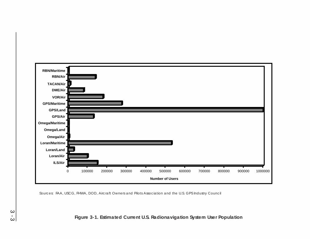
3 - 3
ILS/Air
Loran/Land
Omega/Air
Omega/Maritime
GPS/Land
VOR/Air
TACAN/Air
RBN/Maritime
0 100000 200000 300000 400000 500000 600000 700000 800000 900000 1000000
Number of Users
RBN/Air
DME/Air
GPS/Maritime
GPS/Air
Omega/Land
Loran/Maritime
Loran/Air
Figure 3-1. Estimated Current U.S. Radionavigation System User Population
Sources: FAA, USCG, FHWA, DOD, Aircraft Owners and Pilots Association and the U.S. GPS Industry Council

Approach and Landing: Nonprecision approach navigation requirements arepresently met using ILS localizer, VOR, VOR/DME, VORTAC, TACAN, GPS,Loran-C, or NDB. Loran-C and GPS are approved as supplemental systems.Precision approach and landing requirements are presently met by ILS (Categories I,II, and III) and MLS (a limited number of Category I systems only).
3.1.2 Marine Navigation
Marine navigation comprises four major phases: inland waterway, harbor entranceand approach, coastal, and oceanic. The phase of navigation in which a marineroperates determines which radionavigation system or systems will be the mostuseful. While some radionavigation systems can be used in more than one phase ofmarine navigation, the most promising system to meet the most stringentrequirements of the harbor entrance and approach and inland waterway phases ofmarine navigation is DGPS. With regard to the coastal phase of navigation, DGPSwill provide the navigational features currently being met by Loran-C as it is used inthe repeatable mode of navigation.
Inland Waterway Phase: This phase of navigation is concerned primarily withthose vessels which are not oceangoing. Specific quantitative requirements fornavigation on rivers and other inland waterways have been developed. Visual andaudio aids to navigation, radar, and intership communications are presently used toenable safe navigation in those areas. However, DGPS is expected to play anincreasing role in this phase of navigation.
Harbor Entrance and Approach Phase: Navigation in the harbor entrance andapproach areas is accomplished through use of fixed and floating visual aids tonavigation, radar, and audible warning signals. The growing desire to reduce theincidence of accidents and to expedite movement of traffic during periods ofrestricted visibility and ice cover has resulted in the implementation of Vessel TrafficServices and investigation of the use of radio aids to navigation. DGPS is anticipatedto meet the navigational needs for this phase of navigation, but it will be necessaryto integrate it with an electronic chart display information system (ECDIS). DGPScoverage includes all coasts of the continental U.S. and parts of Alaska, Hawaii, andthe Great Lakes. The system provides between 2 and 20 meter accuracy.
Coastal Phase: Requirements for operation within the coastal area are now met byLoran-C, which was fully implemented by 1980. GPS now also meets these needs.Radio Direction Finders (RDF), required in some merchant ships by internationalagreement for search and rescue purposes, are also used with the radiobeacon systemfor navigation.
Ocean Phase: Navigation on the high seas is accomplished by the use of dead-reckoning, celestial fixes, self-contained navigation systems (e.g., inertial systems),Loran-C, Omega, and GPS. GPS reached its Initial Operational Capability (IOC) onDecember 3, 1993, and is now the system of choice for this phase of marinenavigation. Worldwide coverage by most ground-based systems such as Loran-C is
3 - 4
not practicable. The Omega system, however, with all eight stations operational,does provide essentially worldwide coverage.
3.1.3 Land Navigation
GPS, in conjunction with other systems, is used in land vehicle navigation.Government and industry have sponsored a number of projects to evaluate thefeasibility of using existing and proposed radionavigation systems for landnavigation. Operational tests have been completed that use in-vehicle navigationsystems and electronic mapping systems to provide real-time route guidanceinformation to drivers. GPS and Loran-C are used for automatic vehicle location forbus scheduling and fleet management. Operational tests are either planned or inprogress to use radionavigation for route guidance, in-vehicle navigation, providingreal-time traffic information to traffic information centers, and improving emergencyresponse. Several transit operational tests will use automatic vehicle location forautomated dispatch, vehicle re-routing, schedule adherence, and traffic signal pre-emption. Railroads have tested and continue to test GPS as a part of positivetrain control systems for freight as well as high-speed passenger train operations.GPS, Loran-C, and dead-reckoning/map-matching are being developed as systemsthat take advantage of radionavigation systems and at the same time improve safetyand efficiency of land navigation.
3.1.4 Uses Other Than Navigation
These uses are concerned primarily with the application of GPS for geodesy andsurveying, positioning in support of mapping, charting, and geographicalinformation systems, monitoring of Earth motions, meteorological parametermonitoring, and time and frequency determination. Users with these applicationsrepresent a large percentage of the GPS user community and involve all levels ofgovernment, academia, and industry. Many of the products supported by theseapplications are those traditionally provided by the Federal government. Theseinclude the National Spatial Reference System, nautical and aeronautical charts,weather prediction, earthquake studies, and inland waterways management. In theInland Waterways, Harbor Entrance and Approach and Coastal Phases, DGPS isbeing used extensively by the U.S. Coast Guard to position floating aids as well asfixed aids to navigation. Additionally, the U.S. Army Corp of Engineers is usingDGPS to conduct surveying, aid positioning, dredging operations, and revetmentmaintenance.
Many applications of GPS and augmented GPS are anticipated for Federal, state,and local governments, industry, and consumers. The Government does not have aresponsibility under law to provide radionavigation systems for these users.However, these applications represent a large (and growing) percentage of the civilradionavigation user community and are recognized in the radionavigation planningprocess.
3 - 5
3.1.5 Space Applications
There are numerous uses of GPS for space navigation; many are discussed inSection 2. Several spacecraft, including the ISSA, the Space Shuttle, the StudentNitrous Oxide Explorer, and the small satellites Lewis and Clark are using or will beusing GPS for navigation. Some of these spacecraft will use GPS for support ofinstrument pointing, scientific data processing, and, in the case of the Space Shuttle,during approach and landing as well as on orbit. The private sector is alsoimplementing the use of GPS in space applications.
3.2 Existing and Developing Systems - Status and Plans
Figure 3-2 shows the operating plans for Federally provided common-useradionavigation systems.
3.2.1 Global Positioning System (GPS)
GPS is a space-based positioning and navigation system designed to provideworldwide, all weather, passive, three-dimensional position, velocity, and time datato a variety of civil and military users. GPS provides a Standard Positioning Servicefor all users and a Precise Positioning Service for authorized users.
A. User Community
The GPS user community has grown exponentially in the past two years and thatgrowth is expected to continue. Rapid growth has occurred in all modes oftransportation. Non-transportation use is also growing at a rapid rate and includesusers employed in surveying, farming, resource exploration, and law enforcement.The GPS signal specification defines the SPS which is designed to support civil GPSapplications. The GPS Precise Positioning Service (PPS) is restricted to U.S. ArmedForces, U.S. Federal agencies, and selected allied Armed Forces and governments.These restrictions are based on national security considerations.
B. Operating Plan
GPS will be the primary Federally funded radionavigation system for the foreseeablefuture. Initial Operational Capability (IOC) was declared December 8, 1993 whenthe DOD determined that the SPS, described in memoranda of agreement betweenthe DOD and DOT, could be sustained. The USCG and FAA subsequentlyauthorized GPS for civil transportation use. DOD Full Operational Capability (FOC)was announced on July 17, 1995 after the 24-satellite constellation was completelytested for military functionality (a milestone that does not have any significantimpact on civil users).
All routine command and control functions are performed from the Master ControlStation in Colorado Springs, Colorado using its dedicated network of remotemonitor stations and ground antennas. The GPS constellation is configured and
3 - 6

3 - 7
System
Year
GPS
Maritime DGPS
WAAS
LAAS
Loran-C
Omega
VOR/DME
TACAN
ILS Cat I
ILS Cat II/III
MLS
Transit
AeroNDB (Non-ILS)
Maritime NDB(Non-DGPS)
90 95 2000 2005 2010 2015
Begin Phaseout Terminate
Begin Phaseout
Begin Phaseout
Begin Phaseout
Terminate
Terminate
Terminate
Terminate
Terminate
Terminate
Terminate
FOCIOC
IOC*
FOCIOC
Begin Phaseout
Standards
(Alaska)
* See Section 3.2.2.1B
Terminate
Figure 3-2. Radionavigation Systems Operating Plan

operated to provide the SPS signals to civil users in accordance with the GPSStandard Positioning Service Signal Specification (Ref. 9). The DOD will maintain a24-satellite constellation. Replacement satellites will be launched on an expectedfailure strategy (a replacement satellite is launched when there are indications that asatellite should be replaced).
The DOD and DOT have agreed that representatives from the DOT will be locatedwithin the Master Control Station and at the GPS Joint Program Office to participatein the day-to-day system operations, system development, and future requirementsdefinitions.
Any planned disruption of the SPS in peacetime will be subject to a minimum of 48-hour advance notice provided by the DOD to the USCG Navigation InformationService (NIS) and the FAA Notice to Airman (NOTAM) system. A disruption isdefined as periods in which the GPS is not capable of providing SPS as specified inthe GPS Standard Positioning Service Signal Specification (Ref. 9). Unplannedsystem outages resulting from system malfunctions or unscheduled maintenance willbe announced by the NIS and NOTAM systems (see Appendix A) as they becomeknown.
The FAA’s GPS overlay initiative, which permits use of GPS to fly most existingNPA procedures, is of particular significance in achieving early operational benefitsfrom GPS. The convenience of GPS for executing the thousands of existing VOR-and NBD-based NPAs was made immediately available to suitable equipped aircraft.In addition to “overlay” NPAs, the FAA is moving aggressively to produce andpublish GPS-based NPAs for runways without existing approaches, as well asimproved approaches (lower minimums) for runways with existing NPAs. The FAAdeveloped more than 500 such approaches in 1995 and an additional 500 in 1996; asof April 1997, more than 700 of these approaches had been published. Initialdevelopment of WAAS-based precision approach procedures will commence in 1998to support WAAS commissioning. A precision approach based on WAAS criteriawill be designed for each runway end that is currently served by an existingconventional approach procedure. In addition, an NPA procedure will be developedwith each precision approach procedure. The NPA will be usable by both WAAS andTSO-C129 receivers.
C. Spectrum
The L1 links of GPS and the Russian GLONASS system, the present principalelements of the ICAO GNSS, operate in the 1559-1610 MHz frequency band. Thisis the sole band that is identified worldwide for the satellite-based aeronauticalradionavigation requirements of civil aviation. The GPS L1 carrier frequency is1575.42 MHz. WAAS, when it becomes operational, will utilize the same band andcarrier frequency as GPS L1. Additionally, a system of pseudolites which wouldshare the GPS L1 frequency has been proposed as an enhancement for LAAS.
3 - 8

The GPS L2 link shares the 1215-1260 MHz frequency band with the GLONASSL2 link and with the nationwide joint surveillance system radar network operated byDOD and FAA. The GPS L2 carrier frequency is 1227.6 MHz.
A second civil frequency is planned to enhance the ability of GPS to support civilusers. It is needed for mitigation of ionospheric-delay estimation errors and as abackup for the GPS L1 link. A specific frequency for this purpose is to beidentified.
3.2.2 GPS Augmentations
Unaugmented GPS will not meet all performance requirements for aviation, for theharbor entrance and approach phase of marine navigation, or for many landtransportation applications. For example, an aircraft must have at least five satellitesin view above a mask angle of 7.5 degrees in order to provide receiver autonomousintegrity monitoring (RAIM). This condition is not always satisfied with the existingGPS constellation, resulting in so-called “RAIM holes” and limiting GPS to use as asupplemental navigation system. To meet the requirements for Fault Detection andExclusion (FDE), at least six satellites with good geometry are necessary. Some typeof augmentation is required for GPS to meet the requirements of an airspace.
GPS may exhibit variances from a predicted grid established for navigation,charting, or derivation of guidance information. This variance may be caused bypropagation anomalies, errors in geodesy, accidental perturbations of signal timing,and the implementation of Selective Availability (SA).
Adverse effects of these variances may be substantially reduced, if not practicallyeliminated, by differential techniques. In such differential operation, a referencestation is located at a fixed point (or points) within an area of interest. GPS signalsare observed in real time and compared with signals expected to be observed at thefixed point. Differences between observed signals and predicted signals aretransmitted to users as differential corrections to upgrade the precision andperformance of the user’s receiver.
Non-navigation users of GPS who require few-centimeter accuracy or employ postprocessing to achieve few-decimeter to few-meter accuracy often employaugmentation somewhat differently from navigation users. For post processingapplications using C/A code range, the actual observations from a reference station(rather than correctors) are provided to users. The users then compute correctors intheir reduction software. Surveyors and other users who need subcentimeter to few-centimeter accuracy in positioning from post-processing use two-frequency carrierphase observations from reference stations, rather than range data. The CORSsystem is designed to meet the needs of both of the above types of these users.
3.2.2.1 Maritime Differential GPS
The USCG maritime DGPS system provides service for coastal coverage of thecontinental U.S., the Great Lakes, Puerto Rico, portions of Alaska and Hawaii, and
3 - 9

portions of the Mississippi River Basin. Maritime DGPS uses fixed GPS referencestations which broadcast pseudo-range corrections using radionavigationradiobeacons. The USCG DGPS system provides radionavigation accuracy betterthan 10 meters (2 drms) for U.S. harbor entrance and approach areas.
A. User Community
Initially the U.S. Coast Guard identified four missions to be supported by theimplementation of DGPS:
• Harbor Entrance and Approach Phase navigation
• Vessel Traffic Services (VTS)
• Aids to Navigation (ATON) positioning
• Exclusive Economic Zone (EEZ) surveying
The first is the only listed mission that requires navigation capability for bothgovernment and public users. The other three are government missions requiring apositioning service. In addition to the four Coast Guard identified missions, the U.S.Army Corp of Engineers (USACE) has partnered with the U.S. Coast Guard toestablish DGPS along many of the navigable inland rivers of the U.S. As a result,USACE surveying, positioning, dredging, revetment maintenance, and othernavigation related activities are to be accomplished with improved levels ofefficiency. When the Coast Guard’s DGPS service has been validated to satisfy theUSCG DGPS performance specifications (Appendix A, section A.2.2.1), the systemwill be declared Full Operational Capability (FOC). Once achieved, the Coast Guardwill initiate a regulatory project to amend the carriage requirements of theNavigation Safety Regulations to require carriage of DGPS equipment for vesselsentering and leaving U.S. waterways.
B. Operating Plan
The USCG declared Initial Operational Capability (IOC) for maritime DGPS serviceon January 30, 1996. The IOC phase is identified by the system’s ability to transmitDGPS signals from 47 of its 48 planned sites along selected portions of the nation’scoastline and major inland rivers. During IOC, DGPS signals are provided with fullintegrity and, when and where available, are fully useable for navigationalapplications. To expedite service, the USCG entered the IOC phase using existingequipment which cannot meet the high standards (as described in Appendix A,Section A.2.2.1) of a system with full operational capability. The 48th site, located inKey West, will transmit DGPS corrections by the end of 1996.
The USCG DGPS system will achieve FOC when it is capable of meeting theUSCG DGPS performance specifications (Appendix A, section A.2.2.1). Severalimprovements are required to reach these high levels of performance in availability,reliability, and coverage. These improvements, initiated in 1996, include completion
3 - 10

of the planned 48-site system, verification of system coverage areas, and installationof replacement beacon transmitters and upgraded beacon antenna systems. Asvalidated needs for maritime DGPS service expand, and funding becomes available,additional sites will be added to the USCG DGPS system.
Recommended standards for maritime DGPS corrections have been developed bythe Radio Technical Commission for Maritime Services (RTCM) Special Committee104. The USCG is represented on this subcommittee and is using the SC-104standard for its DGPS system. There are DGPS reference stations available in themarket today which are compatible with RTCM Special Committee 104 standard.
3.2.2.2 Aeronautical GPS Wide Area Augmentation System (WAAS)
The FAA WAAS is a safety-critical system consisting of the equipment and softwarewhich augments GPS. The WAAS provides a signal-in-space to WAAS users tosupport en route through precision approach navigation. The WAAS users include allcertified aircraft using the WAAS for any approved phase of flight. The signal-in-space provides three services: (1) integrity data on GPS and Geostationary EarthOrbit (GEO) satellites, (2) differential corrections of GPS and GEO satellites toimprove accuracy, and (3) a ranging capability to improve availability andcontinuity.
The GPS satellite data is received and processed at widely dispersed sites, referredto as Wide-area Reference Stations (WRS). This data is forwarded to processingsites, referred to as Wide-area Master Stations (WMS), which process the data todetermine the integrity, differential corrections, residual errors, and ionosphericinformation for each monitored satellite and generate GEO satellite parameters. Thisinformation is sent to a Ground Earth Station (GES) and uplinked along with theGEO navigation message to the GEO satellites. The GEO satellites downlink thisdata on the GPS L1 frequency with a modulation similar to that used by GPS.
In addition to providing GPS integrity, the WAAS verifies its own integrity andtakes any necessary action to ensure that the system meets performancerequirements. The WAAS also has a system operations and maintenance functionthat provides information to FAA maintenance personnel.
A. User Community
Substantial benefits will accrue to both users and providers as the WAAS becomesoperational and the aviation community transitions to WAAS avionics. Near-termuser benefits will result from the use of a single navigation receiver that providesarea navigation for all phases of flight and a ten-fold increase in runways approvedfor precision approaches. When combined with necessary improvements in air trafficcontrol automation, additional user benefits are expected to be derived from reducedIFR separations and more efficient routings. Near-term provider benefits will bederived from the decommissioning of redundant navigation systems and more cost-effective instrument approaches. The WAAS is also expected to be used extensively
3 - 11

for numerous other civil applications where improved accuracy, integrity andavailability are needed.
B. Operating Plan
The FAA is conducting a major system acquisition consisting of the WAASoperational system and functional verification system. The program strategy is toquickly field an initial WAAS which meets the basic requirements, and to enhancethe system to meet the full WAAS requirements through a series of contract options.Implementation of the end-state WAAS will be accomplished in an evolutionaryfashion over an estimated six-year period. The initial WAAS will include an initialoperational system and a functional verification system. It will be upgraded througha series of pre-planned product improvements to eventually meet all the performancerequirements of the WAAS end-state system.
Initial WAAS is expected to be commissioned in 1999, and to be certified as aprimary means of navigation for en route and terminal operations and limitedprecision approach service. WAAS is envisioned to reach its full operationalcapability in 2001 with multiple redundancy to support all phases of flight from enroute to Category I precision approaches.
C. Spectrum
The WAAS will operate as an overlay on the GPS L1 link and will share the 1559-1610 MHz frequency band with it. WAAS will also require codeless access to GPSL2 signals in the 1215-1260 MHz band to enhance system accuracy until such timeas the second coded civil GPS signal is operational. The exact timeline andconditions will be specified in a jointly developed DOD/DOT transition plan to becompleted by March 1998.
3.2.2.3 GPS Local Area Augmentation System (LAAS)
The LAAS is a local GPS augmentation where the corrections to GPS (and WAAS)signals are broadcast to aircraft within line of sight of a ground reference station.LAAS is expected to support Category II/III applications. The system is alsoexpected to provide Category I precision approaches at some high capacity airportsand at locations where WAAS is unable to provide Category I precision approaches.Moreover, the LAAS will be used in high speed turnoff, missed approach, departure,vertical takeoff, and surface operations.
The FAA is working with U.S. industry and universities to determine the technicalfeasibility of using satellite-based systems for Category II and III precisionapproaches. Several cooperative projects have already demonstrated the ability ofboth advanced code and kinematic carrier phase differential techniques to meet theaccuracy requirements of Category III autoland approaches. Several satisfactoryintegrity techniques have also been demonstrated, but must be validated.
3 - 12

The work in this area is being closely coordinated with the development of localarea differential GPS (LADGPS) systems for Special Category I (SCAT-I) precisionapproaches which are being funded by private industry. The FAA plans to developLAAS specifications by late 1998 and to develop a prototype system. It is uncertainwhether this will lead to a Federally funded full scale development activity andproduction buy of a large quantity of systems. Procurement depends on a pendinginvestment analysis and the consideration of alternative funding mechanisms.Although the exact date is uncertain, the FAA expects LAAS Category II/IIIprecision approaches to be available for public use by 2005.
The FAA is also conducting research on providing airport surface traffic surveillanceand guidance based on LAAS-augmented GPS.
The international community is currently evaluating alternatives for the spectralplacement of LAAS. At present, the 108-117.975 MHz frequency band, currentlypopulated by VORs and ILSs, is the leading candidate, but other alternatives such asthe 328.6-335.4 MHz and 5000-5250 MHz bands are also being considered. Anetwork of pseudolites sharing GPS L1 spectrum in the 1559-1610 MHz band hasbeen proposed as an enhancement for LAAS.
3.2.2.4 The Continuously Operating Reference Station (CORS) System
The CORS system is a GPS augmentation being established by the NationalGeodetic Survey (NGS) to support non-navigation, post-processing applications ofGPS. The CORS system provides code range and carrier phase data from anationwide network of GPS stations for access by the Internet. As of September1996, data were being provided from about 75 stations. NGS will precisely positionthe CORS relative to the North American datum of 1983 (NAD 83), the legal datumof the U.S., as well as to the accepted international reference system, the IERSTerrestrial Reference Frame (ITRF). This will allow users to relate themselves to acommon coordinate system.
The CORS system takes data to a Central Facility from the contributing stationsusing either the Internet or a telephone packet service (such as x.25). At the CentralData Facility, the data are converted to a common format, quality controlled, andplace in files for access via Internet. The data are available via Internet for 31 days,after which they are archived on CD ROM. In addition to the data, the Central DataFacility provides software to support extraction, manipulation, and interpolation ofthe data. The precise positions of the CORS antennas are computed and monitored.In the future it is planned to compute and provide ancillary data, such as multipathmodels and tropospheric and ionospheric refraction models, to improve the accuracyof the CORS data.
The observational data provided by the CORS system is being used by government,academia, and industry groups to support most of the applications described insection 2.6 above. Currently, users are downloading about 2 gigabytes of data permonth. The largest user group in terms of number of bytes downloaded are academic
3 - 13

and government research groups involved in geophysical studies of Earth movement.However, the largest number of users are private industry and Federal, state and localgovernment users involved in surveying, mapping, charting, and GIS applications.These users require lesser quantities of data to support their applications.
NGS has implemented CORS by making use of stations established by other groups,rather than by building an independent network of reference stations. In particular,use is being made of data from stations operated by components of DOT to supportreal time navigation requirements. More than half of the stations now providing datafor the CORS system are the stations of the USCG DGPS system described in section3.2.2.1 above. Stations of the WAAS network (described in section 3.2.2.2 above)will be CORS compatible, as well as stations that might be established in the futureby DOT to support land navigation. Other stations currently contributing data to theCORS system include stations operated by the National Oceanic and AtmosphericAdministration (NOAA) and NASA in support of crustal motion activities, stationsoperated by state and local governments in support of surveying applications, andstations operated by NOAA’s Forecast Systems Laboratory in support ofmeteorological applications.
3.2.3 Loran-C
Loran-C was developed to provide military users with a radionavigation capabilityhaving much greater coverage and accuracy than its predecessor (Loran-A). It wassubsequently selected as the Federally provided radionavigation system for civilmarine use in the U.S. coastal areas. It is currently designated by the FAA as asupplemental system in the NAS.
A. User Community
Users of Loran-C have been one of the largest communities employing a singleradionavigation system. This situation is changing now that GPS has achieved FOCand GPS user equipment continues to drop in price. Use of the system is expected todecline with no growth anticipated. It is anticipated that users will purchase GPS oraugmented GPS equipment and begin the transition away from Loran-C.
B. Operating Plan
Loran-C was designated as the Federally provided navigation system for the U.S.coastal areas in 1974. The domestic Loran-C system as it is operated and supportedby the USCG consists of 29 transmitting stations comprising 12 Loran-C chains.Included in this chain count is the Russian-American chain and the three Loran-Cchains operated in cooperation with Canada. (The coverage of the Loran-C systems isshown in Appendix A.)
Current use of the Loran-C system appears to be leveling off and will most likelydecrease as GPS and DGPS fills the market place. The U.S. will terminate operationof the Loran-C system by December 31, 2000. The Coast Guard Authorization Act of
3 - 14

1996 requires, however, that the Department of Transportation prepare a report onthe future use and funding of Loran-C. The report will be developed in consultationwith users of the Loran-C system and in cooperation with the Secretary ofCommerce.
C. Spectrum
Loran-C operates in the 90-110 kHz frequency band. No future civil aeronauticaluses are envisioned for that band after Loran-C has been decommissioned.
3.2.4 Omega
The Omega system was developed and implemented by the Department of the Navy,with the assistance of the USCG and with the participation of six partner nations. Itprovides worldwide, all-weather radionavigation capability.
A. User Community
International civil use of Omega includes sole means oceanic aircraft navigationbecause of its worldwide coverage. It is also approved by the FAA for use as asupplement for domestic high altitude en route airspace navigation.
The precise timing aspects of Omega make it possible to obtain profiles of windspeed and direction from ground level to over 30 km with an Omega-basedmeteorological upper-air observation system. Omega-equipped meteorologicalsondes are launched annually from approximately 200 locations around the world.
B. Operating Plan
The eight-station Omega configuration has been operational since August 1982.Omega stations are located in Norway, Liberia, La Reunion Island, Argentina,Australia, and Japan, and in the U.S., in North Dakota and Hawaii. The U.S.operates the two stations located in the U.S. and has bilateral agreements with thepartner nations that govern partner nation operation. The USCG has operationalcontrol of the system and has operated the system for the FAA since January 1,1995.
With the achievement of GPS FOC, it is anticipated that aviation users will quicklytransition from Omega to GPS. Therefore, the U.S. will terminate its role in theOmega system on September 30, 1997.
C. Spectrum
Omega operates in the 9-14 kHz frequency band. No future civil aeronautical usesare envisioned for that band after Omega has been decommissioned.
3 - 15

3.2.5 VOR and VOR/DME
VOR was developed as a replacement for the Low-Frequency Radio Range toprovide a bearing from an aircraft to the VOR transmitter. A collocated DMEprovides the distance from the aircraft to the DME transmitter. At most sites, theDME function is provided by the TACAN system which also provides azimuthguidance to military users. Such combined facilities are called VORTAC stations.Some VOR stations are used for broadcast of weather information.
A. User Community
Approximately 69 percent of all navaid-equipped general aviation aircraft had morethan one VOR receiver in 1993. An even higher percent had at least one VOR butthe exact number cannot be derived from the available statistics.
VOR is the primary radionavigation aid in the National Airspace System and is theinternationally designated standard short-distance radionavigation aid for air carrierand general aviation IFR operations. It is easy to use and is generally liked by pilots.Because it forms the basis for defining the airways, its use is an integral part of theair traffic control procedures.
B. Operating Plan
The FAA operates 1012 VOR, VOR/DME, and VORTAC stations including 150VOR-only stations. The number of stations is expected to remain stable until theVOR/DMEs begin to be decommissioned in 2005. The DOD also operates stationsin the U.S. and overseas that are available to all users.
A small increase in the number of users equipped with VOR is expected over thenext several years due to an increase in the aircraft population operating in the U.S.During this time, many users that are equipping their aircraft for VFR operation maychoose to equip with GPS in preference to VOR. VOR/DME will still be requiredfor IFR flight until the WAAS is approved for primary means navigation. It is thenexpected that VOR equipage will begin to rapidly decrease.
The current VOR/DME network will be maintained until 2005 to enable aircraft tobecome equipped with WAAS avionics and to allow the aviation community tobecome familiar with the system. Plans for expansion of the network are limited tosite modernization or facility relocation, and the conversion of sub-standard VORsto a Doppler VOR configuration. The phaseout of the VOR/DME network isexpected to begin in 2005 and to be complete by 2010.
C. Spectrum
VOR operates in the 108-117.975 MHz frequency band. It shares the 108-111.975MHz portion of that band with ILS. The FAA and the rest of the civil aviationcommunity are investigating several potential aeronautical applications of the 108-117.975 MHz band for possible implementation after VOR and ILS have been
3 - 16

partially or completely decommissioned. One of those future applications is LAAS.Another is the expansion of the present 117.975-137 MHz air/ground (A/G)communications band to support the transition to, and future growth of, the next-generation VHF A/G communications system for air traffic services.
DME operates in the 960-1027, 1033-1087, and 1093-1215 MHz subbands of the960-1215 MHz band. It shares those subbands with TACAN. The FAA and the restof the civil aviation community are investigating potential aeronautical applicationsof those subbands for implementation after DME and TACAN have been partially orcompletely decommissioned. These future applications include:
• Automatic Dependent Surveillance, Broadcast (ADS-B), a system that willenable aircraft to report their positions, velocities, and related dataautomatically during flight.
• Traffic Information Services (TIS), in which processed surveillance data willbe reported automatically from ground stations to aircraft in flight.
• Terrestrial or satellite-based A/G transfer of voice and data traffic for CNSservices.
• Potential future CNS applications to support Free Flight.
The FAA is also considering the retention of a subset of the nationwide VOR/DMEnetwork. Continued use of some of the 108-117.975 MHz band would be needed tosustain the VOR elements of such a network. A substantial portion of the 960-1215MHz band would be required to support its DME elements.
3.2.6 TACAN
TACAN is a UHF radionavigation system which is the military counterpart ofVOR/DME. TACAN is the primary tactical air navigation system for the militaryservices ashore and afloat. TACAN is often collocated with the civil VOR stations(VORTAC facilities) to permit military aircraft to operate in civil airspace.
A. User Community
There are presently approximately 14,500 aircraft which are equipped to determinebearing and distance to TACAN beacons. These consist primarily of Navy, AirForce, and to a lesser extent, Army aircraft. Additionally, allied and third worldmilitary aircraft use TACAN extensively.
Because of propagation characteristics and radiated power, TACAN is limited toline-of-sight and is limited to approximately 180 miles at higher altitudes. As withVOR/DME, special consideration must be given to location of ground-basedTACAN facilities, especially in areas where mountainous terrain is involved due toits line-of-sight coverage.
3 - 17
B. Operating Plan
DOD presently operates 173 TACAN beacons and the FAA operates 640 TACANbeacons for DOD. Present TACAN coverage ashore will be maintained until phasedout in favor of GPS. However, GPS without enhancement cannot replace theTACAN function afloat (moving platforms). Civil DME and the distance-measuringfunctions of TACAN will continue to be the same.
The DOD requirement for and use of land-based TACAN will terminate whenaircraft are properly integrated with GPS and when GPS is approved for alloperations in national and international controlled airspace. Proper integrationrequires hardware and software modifications to GPS user equipment to meetnavigation accuracy, integrity, availability, and continuity of service requirements.These modifications as well as development of operational procedures andnavigation databases will require a transition period where TACAN must beretained. The target date to begin TACAN phaseout is 2005.
C. Spectrum
TACAN operates in the 960-1027, 1033-1087, and 1093-1215 MHz subbands of the960-1215 MHz aeronautical radionavigation frequency band. It shares those bandswith DME. The FAA and the rest of the civil aviation community are investigatingpotential aeronautical applications of those subbands, for implementation afterTACAN and DME have been partially or completely decommissioned. Possiblefuture applications are noted in Section 3.2.5.
3.2.7 ILS
ILS provides aircraft with precision vertical and lateral navigation (guidance)information during approach and landing. Associated marker beacons or DMEequipment identify the final approach fix, the point where the final descent to therunway is initiated.
A. User Community
Federal regulations require U.S. part 121 air carrier aircraft to be equipped with ILSavionics. It is also extensively used by general aviation aircraft. A slight increase inthe number of users equipped with ILS is expected over the next several years due toan increase in the aircraft population operating in the U.S. ILS equipage rates arethen expected to rapidly decrease once the WAAS is approved for Category Iapproaches.
Because ILS is an ICAO standard landing system, it is extensively used by aircarrier and general aviation aircraft of other countries.
3 - 18

B. Operating Plan
The FAA operates nearly 900 ILS systems in the NAS, of which 81 are Category IIor Category III systems. In addition, the DOD operates 165 ILS facilities in the U.S.New ILS sites may be installed prior to the availability of precision approachesusing the WAAS if they are cost-beneficial.
ILS is a standard civil landing system in the U.S. and abroad, and is protected byICAO agreement to January 1, 2010. ICAO has endorsed the Global NavigationSatellite System (GNSS) as the core system for international use. The U.S. willcontinue to promote the international acceptance and implementation of GPS as partof the GNSS for navigation in all phases of flight.
The WAAS is expected to provide a limited Category I precision approach servicebeginning in late 1998, and the system is anticipated to become fully operational in2001. ILS will remain in service together with WAAS precision approaches to allowusers an opportunity to equip with WAAS receivers and to become comfortable withits service. The phaseout of Category I ILS is expected to begin in 2005 and to becomplete by 2010.
The date when LAAS Category II/III approaches will become available is lesscertain. Extensive testing has demonstrated the ability of LAAS to meet CategoryII/III accuracy requirements. Analyses and field tests are currently in progress todemonstrate that the integrity requirements can also be achieved. Following this,several years will be required to select among the available techniques and developand certify an operational LAAS system.
Until LAAS systems are available, the FAA plans to meet upgrade and newCategory II/III requirements with ILS. Upgrades and new system establishmentswill be done only if cost beneficial, given the expected availability of LAASCategory II/III approaches by 2005. The FAA does not anticipate phasing out anyCategory II/III ILS systems prior to 2005. The phaseout is expected to be completeby 2010.
ILS limitations manifest themselves in four major areas. First, performance ofindividual systems can be affected by terrain and man-made obstacles, e.g.,buildings and surface objects such as taxiing aircraft and snowbanks. These itemsmay impose permanent use constraints on individual systems or limit their use atcertain times. Second, the straight-line approach path inherent in ILS constrainsairport operations to a single approach ground track for each runway. In contrast,both augmented GPS and MLS will allow multiple ground track paths forapproaches to the active runway as well as provide a steeper glide slope capabilityfor Short Take-Off and Landing (STOL) aircraft. Third, even though the new 50 kHzfrequency spacing has doubled the ILS channel availability, frequency saturationlimits the number of systems that can be installed. Frequency saturation occurs whenILS facilities, in close proximity with inadequate frequency separation, producemutual interference. Fourth, interference from commercial FM broadcast stations inthe adjacent frequency band limits ILS frequency assignments in many congestedlocations; however, this is more of a concern in other countries than in the U.S.
3 - 19
C. Spectrum
ILS marker beacons operate in the 74.8-75.2 MHz frequency band. Since all ILSmarker beacons operate on a single frequency (75 MHz), the aeronauticalrequirements for this band will remain unchanged until ILS has been completelyphased out. No future aeronautical uses are envisioned for this band after ILS hasbeen fully decommissioned.
ILS localizers share the 108-111.975 MHz portion of the 108-117.965 MHz bandwith VOR. As noted in Section 3.2.5, the FAA and the rest of the civil aviationcommunity are investigating several potential aeronautical applications of this bandfor possible implementation after VOR and ILS have been partially or completelydecommissioned. One of those future applications is LAAS. Another is theexpansion of the present 117.925-137 MHz A/G communications band to supportthe transition to, and future growth of, the next-generation VHF A/Gcommunications system for air traffic services. Substantial amounts of spectrum inthe 108-111.975 MHz subband will continue to be needed to operate Category II andIII localizers even after Category I ILS has been decommissioned.
ILS glideslope subsystems operate in the 328-335.4 MHz band. The FAA and therest of the civil aviation community are investigating several potential aeronauticalapplications of this band for possible implementation after ILS has been partially orcompletely decommissioned. The inherent physical characteristics of this band, likethose of the 108-111.975 MHz band, are quite favorable to long-range terrestrialline-of-sight A/G communications and data-link applications like LAAS, ADS-B andTIS. Consequently, this band is well suited to provide multiband diversity to suchservices or to serve as an overflow band for them if they cannot be accommodatedentirely in other bands. Substantial amounts of spectrum in this band will continue tobe needed to operate Category II and III ILS glideslope subsystems even afterCategory I ILS has been decommissioned.
3.2.8 MLS
MLS applications are limited to aviation. MLS does not have the siting problems ofILS and offers higher accuracy and greater flexibility, permitting precisionapproaches at more airports. MLS provides DOD tactical flexibility due to its ease insiting and adaptability to mobile operations. However, there is limited user supportfor MLS in the U.S.
A. User Community
A limited procurement of Category I MLS equipment was initiated in 1992.However, the FAA has determined that augmented GPS is feasible for Category Iprecision approach operations and is progressing toward implementation andcertification. Only 29 Category I MLS systems are currently planned to be installed,and the FAA has terminated the development of Category II and III MLS equipment.
3 - 20

The termination of the Category II and III development contracts was primarily abudget decision, supported by initial results of R&D efforts that have demonstratedthe potential for using augmented GPS technology for this application. The FAAretains the option to purchase MLS for Category II and III operations on the openmarket should the decision be made to implement MLS in the future.
B. Operating Plan
The FAA has terminated the development of MLS based on favorable GPS testresults and budgetary constraints. The U.S. does not anticipate additional MLSdevelopment, but could purchase systems on the open market for Category II/IIIoperations if the need should arise in the future. The phaseout of Category I MLS isexpected to begin in 2005 and to be complete in 2010.
C. Spectrum
MLS operates in the 5000-5250 MHz frequency band. The FAA and the rest of thecivil aviation community are investigating potential aeronautical applications of thisband for implementation after MLS has been partially or completelydecommissioned. These include:
• An extension of the tuning range of the Terminal Doppler Weather Radar(TDWR) in order to relieve spectral congestion within its present limitedoperating band.
• Weather functions of the planned multipurpose primary terminal radar thatwill become operational around the year 2013.
The possible use of this band for LAAS is also being considered by the internationalcommunity.
3.2.9 Aeronautical Nondirectional Beacons (NDBs)
Aeronautical nondirectional beacons are used for transition from en route toprecision terminal approach facilities and as nonprecision approach aids at manyairports. In addition, some state and locally owned NDBs are used to provideweather information to pilots. However, GPS and the FAA’s automated weatherobserving system (AWOS) and automated surface observing system (ASOS) havebegun to satisfy the requirement currently met by NDBs. In Alaska and in someremote areas, NDBs are also used as en route facilities.
A. User Community
All air carrier, most military, and many general aviation aircraft carry automaticdirection finders (ADF). However, the importance of ADF is expected to declinewith the increasing popularity of GPS.
3 - 21
Aircraft use radiobeacons as compass locators to aid in finding the initial approachpoint of an instrument landing system, for nonprecision approaches at low trafficairports without convenient VOR approaches, and for en route operations in someremote areas.
The large number of general aviation aircraft that are equipped with radio directionfinders attests to the wide acceptance of radiobeacons by the user community. Theprimary reason for this acceptance is that adequate accuracy can be achieved withlow-cost user equipment. However, now that GPS-based nonprecision approachesare available, transition from the NDB network can begin.
B. Operating Plan
The FAA operates over 700 NDBs. This number is expected to decline steadily overthe next decade due to the increasing popularity of GPS. In addition, there are about200 military NDBs and 800 non-Federally operated NDBs. During the next 10years, FAA expenditures for beacons are planned to be limited to the replacement ofdeteriorated components, modernization of selected facilities, and an occasionalestablishment or relocation of an NDB used for ILS transition.
The FAA expects to decommision NDB facilities where essentially equivalentcapability is provided by VOR beginning in 2000. The remaining stand-alone NDBswill be rapidly phased out after 2005. However, in each case, through consultationwith the user community, aircraft operator desires for continued NDB service will beweighed against the cost of continuing to provide that service. There may be caseswhere operation and maintenance of an NDB will be taken over by an individualoperator or community desiring to delay its phaseout.
NDBs used as compass locators for ILS approaches, where no equivalent ground-based means for transition to the ILS course exists, will be maintained until theunderlying ILS is itself phased out. A separate transition timeline will be developedfor NDBs that define low frequency airways in Alaska.
C. Spectrum
Aeronautical NDBs operate in the 190-435 and 510-535 kHz frequency bands,portions of which it shares with maritime NDBs. Except in Alaskan airspace, nofuture civil aeronautical uses are envisioned for these bands after the aeronauticalNBD system has been decommissioned throughout the rest of the NAS.
3.2.10 Maritime Radiobeacons
Maritime radiobeacons have remained as a backup to more sophisticatedradionavigation systems and as a low-cost, medium accuracy system for vesselsequipped with only minimal radionavigation equipment. Use and number of thesebeacons is dwindling very rapidly.
3 - 22
A. User Community
Radiobeacons are primarily used as homing devices for recreational boaters, but theyalso act as a backup for those users having more sophisticated radionavigationcapability. As selected radiobeacons are modified to broadcast DGPS corrections,those radiobeacons will become a primary element in the harbor entrance andapproach and coastal phases of navigation, used by all vessels, and required forcertain classes of vessels. Due to single carrier operations, which eliminates theMorse tone identifier, USCG DGPS beacons do not conform to traditionalradiobeacon standards.
Maritime radiobeacons have been an acceptable radionavigation tool for pleasureboaters using them for homing purposes, largely due to the adequate service withlow-cost user equipment.
Marine radiobeacons provide a bearing accuracy relative to vehicle heading on theorder of +-3 to +-10 degrees. This might be considered a systemic limitation but, inactual use, it is satisfactory for many navigational purposes. Radiobeacons are notsatisfactory for marine navigation within restricted channels or harbors. They do notprovide sufficient accuracy or coverage to be used as a primary aid to navigation forlarge vessels in U.S. coastal areas.
B. Operating Plan
Four maritime radiobeacons continue to be operated by the USCG. Many of thepreviously-configured maritime radiobeacons have been modified to broadcastDGPS corrections for the USCG DGPS service; therefore, they no longer provideservice as traditional homing devices.
With the availability of low-cost Loran-C and GPS receivers that provide far moreflexible use to the boater, the use of radiobeacons has been continually declining. Asthe USCG conducts evaluation of the need for beacons, those with no identifiableuser base will be discontinued. Maritime radiobeacons not modified to carry DGPScorrection signals are expected to be phased out by the year 2000.
Although some aviation users have benefited from maritime radiobeacons,modulation of maritime radiobeacons with DGPS corrections will make thesebeacons unusable by digital aviation ADFs and may make their use by analog ADFsdifficult.
Radar Transponder Beacons: Radar transponder beacons (RACONs) are short-range radio devices used to provide fixed radar reference points in areas where it isimportant to identify a special location. Currently, they are only used in the marineenvironment. Examples of the use of RACONs are: landfall identification;improvement of ranging to and identification of an inconspicuous coastline;improvement of identification of coastlines permitting good ranging but which areotherwise featureless; improvement of the identification of a particular aid tonavigation in an area where many radar returns appear on the radar display;
3 - 23

provision of a lead to a specific point such as into a channel or under a bridge; andwarning to temporarily mark a new obstruction, or other uncharted or especiallydangerous fixed hazard to navigation.
Though RACONs offer a unique possibility of positive aid identification,uncontrolled proliferation could lead to an unacceptable increase in responsespresented on a ship’s radar display. This could degrade the usefulness of the displayand cause confusion. In 1986, the Code of Federal Regulations was changed (33CFR 66.01-1 (d)) to allow private operation of RACONs with USCG approval. TheUSCG now has about 104 frequency agile RACONs.
3.3 Interoperability of Radionavigation Systems
3.3.1 Overview
Radionavigation systems are sometimes used in combination with each other or withother systems. These combined systems are often implemented so that a majorattribute of one system will supplement a weakness of another. For example, asystem having high accuracy and a low fix rate might be combined with a systemwith a lower accuracy and higher fix rate. The combined system would demonstratecharacteristics of a system with both high accuracy and a high fix rate.
3.3.2 GPS/GLONASS
Manufacturers of navigation and positioning equipment are beginning to developand manufacture combined GPS/GLONASS receivers to take advantage of thesebenefits. Some receivers are on the market with others in the planning stage. TheRTCA SC 159 is developing a MOPS for a combined GPS and GLONASS system.The Airlines Electronic Engineering Committee (AEEC) is developing specificationsfor a multimode receiver which includes GLONASS. The satellite communicationsMOPS and SARPS provide for both GPS and GLONASS protection.
A combination of GPS and GLONASS has several potential benefits over eithersystem alone. Combining the capability in one receiver to navigate using satellitesfrom the GPS and GLONASS constellations results in a receiver with improvednavigation and positioning availability worldwide, improved polar coverage,improved resistance to interference and jamming and improved RAIM and FDE.The FAA has entered into a bilateral agreement with the Russian Federation toinvestigate a combined GPS/GLONASS avionics receiver which could takeadvantage of all 48 satellites of the two constellations.
3 - 24

4Radionavigation System Research
and Development Summary
4.1 Overview
This section describes Federal Government research and development (R&D)activities relating to Federally provided radionavigation systems and their worldwideuse by the U.S. Armed Forces and the civilian community. It is organized in twosegments: (1) civil R&D efforts to be conducted by DOT and other Governmentorganizations for civil purposes, and (2) DOD R&D.
The DOT R&D activities emphasize applications for and enhancement of GPS forcivil uses. GPS has broad multimodal civil and military applications; consequently,there is need for close cooperation between Federal agencies in its evaluation. Sucha cooperative effort will minimize duplication of effort and promote maximumproductivity from the limited resources available for civil research. DOT’sparticipation in the evaluation and development of GPS ensures that benefits can bederived from DOD’s advances in systems technology.
From the point of view of DOT, the analysis of performance requirements of civilnavigation systems involves a variety of complex factors before it can be concludedthat a specific system satisfies the principal objective of ensuring safety andeconomy of transportation. These factors involve an evaluation of the overallperformance and economics of the system in relation to technical and operationalconsiderations, including vehicle size and maneuverability, vehicle traffic patterns,user skills and workload, the processing and display of navigation information, andenvironmental restrictions (e.g., terrain hazards and other obstructions). For thisreason, a DOT comparison of one navigation system to another requires a complexevaluation of accuracy and equipment performance characteristics. As a first step in
4 - 1

the comparison of system capabilities, ten parameters, discussed in Appendix A, canbe identified as follows:
• Signal characteristics
• Accuracy
• Availability
• Coverage
• Reliability
• Fix rate
• Fix dimensions
• System capacity
• Ambiguity
• Integrity
User equipment costs are a major consideration if universal civil participation is tobe achieved. DOT R&D activities may involve evaluations and simulations of low-cost receiver designs, evaluation of future technologies, and determination of futurerequirements for the certification of equipment.
In contrast to DOT, the DOD R&D activities mainly address evaluations by ArmedForces user groups which are identified by military mission requirements andnational security considerations. For this reason, DOD R&D is defined to include allactivities before the final acquisition of a navigation system in accordance withdetailed system specifications. The DOD view of Transit, Loran-C, TACAN, VOR,ILS, and Omega is that these systems are already developed and, therefore, do notrequire R&D.
Although there are some similarities between the DOD and DOT analyses of thesystem parameters, DOD military missions place much greater emphasis on securityand anti-jam capabilities. Such factors as anti-jam capabilities, updating of inertialnavigation systems, input sensors for weapon delivery, portability, and reliableoperation under extreme environmental or combat conditions become very importantin establishing the costs of the navigation equipment.
Concurrent with the Federal R&D programs, the major cost issues will be evaluated.These evaluations and R&D programs will be used to support joint positions relatedto system mix, phase-in and phase-out, and transition strategies for common-usesystems.
The relationship between DOT and DOD R&D programs is based on a continuinginterchange of operational and technical information on radionavigation systems.DOD R&D will be coordinated with DOT R&D under the following guidelines:
4 - 2
• DOT will evaluate the costs of all radionavigation systems which meetidentified civil user requirements.
• DOT will provide DOD with the most current information on civil userrequirements which may have a significant impact on DOD-operatedradionavigation systems.
• Consistent with existing DOD policy, DOD will provide information to DOTon GPS receiver designs that may be applicable to civil receiverdevelopment.
• DOT will conduct studies of GPS performance capabilities of receivers inorder to provide an assessment of their applicability to the civil sector.
• DOD/DOT will not constrain the use of SPS-based differential GPS serviceas long as applicable U.S. statutes and international agreements are adheredto.
• DOT will cooperate in the development of differential correction referencestations for the best possible differential/integrity network.
• DOT will continue to evaluate satellite radionavigation technologies (such asdual capacity receivers) for potential use in an international GlobalNavigation Satellite System (GNSS).
The specific civil R&D activities are discussed in the following sections. Theseactivities have been coordinated to achieve efficient use of the limited fundsavailable for R&D and to avoid duplication of effort. R&D tasks for the individualDOT agencies (FAA, USCG, MARAD, etc.) and related tasks by other governmentagencies are addressed and schedules have been specified if possible so that theresults of the efforts will be of maximum usefulness to all participants in theprogram.
4.2 DOT R&D
DOT R&D activities have been conducted primarily by the USCG, the FAA, theFHWA, and ITS/JPO. Efforts initially were directed primarily toward determiningthe capability of GPS to meet civil user needs in the air, marine, and landtransportation communities. Subsequently, as it became apparent that the GPScapability to be provided to the civil community would not meet all userrequirements, R&D efforts focused on ways of enhancing GPS to meet these civilneeds. Many new efforts are focusing on the development of new and innovativeapplications of GPS.
4.2.1 Civil Aviation
The FAA’s basic R&D activities for the introduction of GPS into the NAS arecurrently focused on the GPS WAAS to satisfy accuracy, coverage, reliability, andintegrity for all phases of flight down through Category I precision approach.
4 - 3
Additional R&D activities to exploit the full capabilities of GPS for civil aviation arecontinuing.
The FAA, through its GPS R&D program, is developing the requirements for use ofGPS in the national airspace. This includes refining the appropriate standards for GPSairborne receivers and developing the air traffic control methodology for handlingGPS area navigation aircraft operation in an environment with non-GPS equippedaircraft. The FAA has certified GPS as a supplemental means of navigation. The useof GPS as a primary means of navigation depends on the successful development,deployment, and operation of the WAAS, as well as the development of appropriatestandards, operating procedures, and avionics. The objective of the FAA is to supportthe integration of GPS and DGPS into the NAS in an evolutionary manner. Theevolving WAAS will be a key component of the NAS precision approach and landingarchitecture. The WAAS is projected to meet all requirements for Category I precisionapproach. Additional augmentation will be required to support Category II and IIIoperations; the FAA has successfully determined the technical feasibility of usingGPS LAAS for Category II and III operations. Other augmentations andauxiliary/hybrid sensors may also be employed, and are currently being examined.There is close cooperation between FAA, DOD, and industry in these efforts. AMemorandum of Agreement between FAA and DOD to implement GPS for civilaviation was signed on May 15, 1992.
The FAA is actively supporting the activities of the ICAO and RTCA, Inc. in thedefinition of the GNSS and associated implementation planning guidelines. TheGNSS is intended to be a worldwide position, velocity and time determinationsystem. ICAO has accepted the GPS and GLONASS as the constituent components ofthe GNSS and is actively developing SARPS. The GNSS will also require end-userreceiver equipment, a system integrity monitoring function, and ground-basedservices augmented as necessary to support specific phases of flight. GPS will be theprimary satellite constellation used for navigation during early GNSS implementation.The FAA’s activities in support of ICAO and RTCA will ensure that satellitenavigation capabilities are implemented in a timely and evolutionary manner on aglobal basis.
The FAA is actively pursuing technology related to GPS augmentation in order toachieve a new primary means of navigation capability. While several methods arebeing analyzed and developed, WAAS is fully endorsed and is being developed by theFAA. This satellite-based augmentation concept has been operationally demonstratedfor use in all phases of flight with a system prototype. The system is expected to beoperational beginning in late 1998.
A. FAA R&D Accomplishments To Date
The FAA has:
• Allowed the use of GPS positioning data as input to multi-sensor navigationsystems for selected IFR phases of flight using existing criteria for operatingminima, flight inspection, obstacle clearance, and ATC separation standards.
4 - 4
• Approved the use of GPS as a supplemental civil aviation navigation systemand as a primary system for oceanic and specified remote areas.
• Published a GPS National Aviation Standard.
• Participated in the development of a Minimum Aviation System PerformanceStandard (MASPS) for GPS private Special Use Category I precisionapproaches and has published an Order describing its use.
• Initiated an “overlay” project to quickly certify about 5,000 GPSnonprecision approaches.
• Supported the satellite navigation activities of the Air Transport Association,the National Business Aircraft Association, and the Aircraft Owners andPilots Association user groups to develop customer capabilities.
• Developed a GPS/GLONASS common receiver test set to collect data andsupport developing avionics MOPS.
• Established cooperative research agreements with aviation communityorganizations such as NASA Ames, Ohio University, Stanford University,Honeywell, and Alaska Airlines to investigate the use of GPS for precisionapproaches.
• Established international cooperation for developing the GNSS through theICAO Future Air Navigation System (FANS) IV research and developmentworking group.
• Participated in the development of the WAAS MOPS.
• Identified the mechanisms contributing to RFI from on-board VHF air-ground radios and developed simple mitigation techniques to eliminate it.
B. Planned FAA R&D Activities
For primary means of navigation, the FAA is pursuing the development of theWAAS to enhance the availability and integrity of GPS. The FAA is also researchingthe development, deployment, and certification of the WAAS as a public-use systemfor Category I precision approaches. There is a continuing certification standardsR&D effort to support Category I.
Emphasis is placed on the GPS-based navigational benefits and associated activitiesfor the oceanic, domestic en route, nonprecision approach, and Category I precisionapproach phases of flight. This reflects that these benefits are near-term, while thecapability of the GPS LAAS to provide navigation guidance for Category II and IIIprecision approaches and airfield surface navigation remains relatively long-termand requires further research.
In parallel with the development of WAAS, the FAA is conducting several studies toaddress concerns related to the GPS/WAAS transition. Unintentional interference to
4 - 5
GPS receivers includes interference caused by such sources as excessive spurious orharmonics emissions from other systems and case penetration of strong undesiredsignals. This category of interference is being investigated, and effective mitigationtechniques and procedures are being developed. Intentional interference, other thanplanned military electronic countermeasures exercises, is a result of illegaltransmission of signals on or close to the GPS frequencies. Such transmissionviolates both national and international radio regulations, and appropriate lawenforcement authorities will take necessary action to terminate such transmission;this will be done with the cooperation of DOD and DOT. The FAA is developing thecapability to quickly and effectively identify and locate sources of RFI to the GPSL1 frequency be it intentional or unintentional.
A study is also underway to determine the effect of ionospheric disturbances on theaccuracy of GPS and WAAS, especially during the peaks of the 11-year sunspotcycle. The next peak, which is expected to occur about the year 2001, will beimportant in determining whether the number of references stations in place issufficient to maintain the required systems accuracy.
Various studies have successfully demonstrated the technical feasibility of usingGPS LAAS for conducting Category I, II, and III approaches. The studies includeFAA-funded demonstrations and studies by industry and academia worldwide.Presently, the ILS ground-based system is the only system used to support CAT II/IIIoperations. GPS without proper LAAS augmentation cannot support CAT II/IIIoperations. Until the LAAS system is declared fully operational, Category II/IIIrequirements will be met by ILS.
Other activities are to:
• Develop CAT II/III standards. This activity contains multiple elements suchas development of TSOs, FAA Orders and ACs, and configurationmanagement updates of NAS documentation.
• Track the GPS signal RF carrier phase during high dynamic movements toobtain sub-meter navigation accuracies.
• Obtain GPS real-time (1 second or less) integrity.
• Provide GPS navigation continuity of service which can meet requirementsfor landing and rollout under very low visibility weather conditions.
Figure 4-1 shows the FAA schedule for the development of GPS performancestandards for civil avionics.
Possibilities exist to develop receiver avionics which combine two radionavigationsignals, such as GPS/GLONASS, and thereby significantly improve user navigationperformance. FAA, in cooperation with industry, is developing standards underwhich a specific system or combination of systems may be certified in aircraftconducting IFR, en route, and terminal area operations, including nonprecisionapproach.
4 - 6
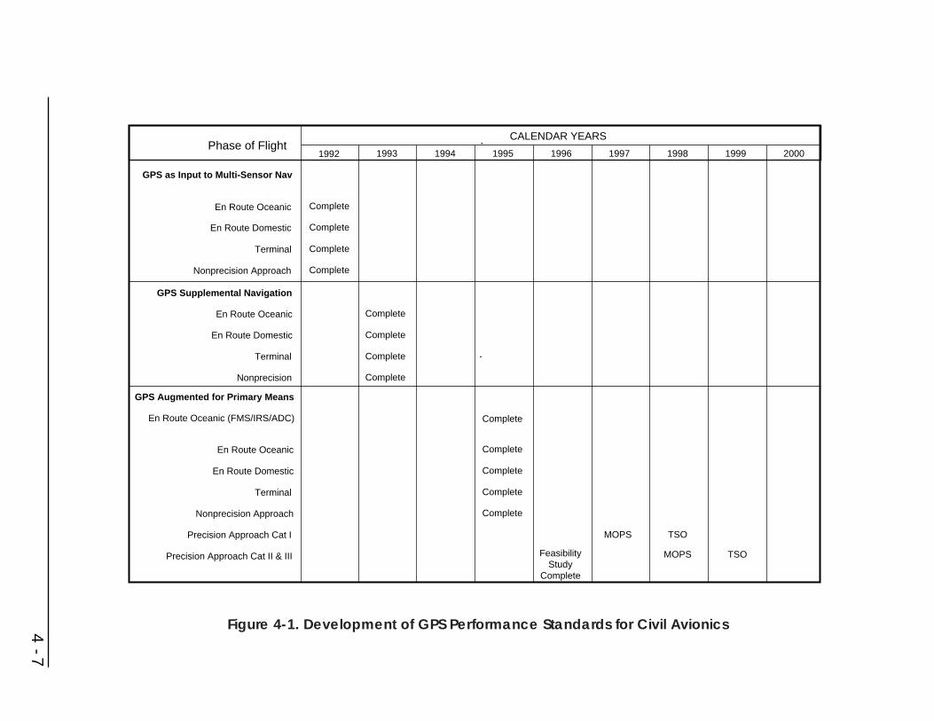
4 - 7
Phase of Flight1992 1993 1994 1995 1996 1997 1998 1999 2000
GPS as Input to Multi-Sensor Nav
En Route Oceanic
En Route Domestic
Terminal
Nonprecision Approach
Complete
Complete
Complete
Complete
GPS Supplemental Navigation
En Route Oceanic
En Route Domestic
Terminal
Nonprecision
Complete
Complete
Complete
Complete
GPS Augmented for Primary Means
En Route Oceanic (FMS/IRS/ADC)
En Route Oceanic
En Route Domestic
Terminal
Nonprecision Approach
Precision Approach Cat I
Precision Approach Cat II & III
CALENDAR YEARS
Complete
Complete
Complete
Complete
Complete
FeasibilityStudy
Complete
MOPS TSO
MOPS TSO
Figure 4-1. Development of GPS Performance Standards for Civil Avionics

In the long term, communications, navigation, and surveillance (CNS) may becombined into an integrated communications and navigation system (ICNS)providing a seamless system for civil users. Low-altitude users, including VFR aswell as IFR traffic, could be accommodated more easily in the NAS since one ICNSsystem would respond to the needs of all users.
ICNS services would extend ATC service to more airspace in support of flexibleroutes. This airspace includes extreme (low and high) altitudes, oceanic, offshore,remote, and urban environments.
Time-based navigation and ATC practices in the en route and terminal environmentwould involve issuing time-based clearances to certain aircraft which can navigatewith sufficient precision to fly space-time profiles and arrive at points in space atspecified times. Aircraft equipped with advanced flight navigation and managementsystems may be able to receive clearances directly from ground automationequipment, and follow such clearances automatically along trajectories of theirchoice, either to maximize fuel efficiency or to minimize time. This will alsoenhance the utilization efficiency of the NAS, allowing increased capacity without aproportional increase in infrastructure expenditures.
Automatic dependent surveillance (ADS) is defined as a function in which aircraftautomatically transmit navigation data derived from onboard navigation systems viaa datalink for use by air traffic control. Automatic dependent surveillance R&D willdevelop functions to permit tactical and strategic control of aircraft. Automatedposition report processing and analysis will result in nearly real-time monitoring ofaircraft movement. Automatic flight plan deviation alerts and conflict probes willsupport reductions in separation minima and increased accommodation of user-preferred routes and trajectories. Graphic display of aircraft movement andautomated processing of data messages, flight plans, and weather data willsignificantly improve the ability of the controller to interpret and respond to allsituations without an increase in workload.
GPS-based navigation offers new opportunities for vertical-flight aircraft to operatemore efficiently in the NAS. As prime examples, significant benefits have beenderived through virtually uninterrupted emergency medical services to hospitals andtrauma centers in all weather operations, undelayed passenger carrying operationsand optimized low-altitude air routes.
Emergency medical services have long recognized the importance of deliveringprompt medical attention and expeditiously transporting patients to and betweenmedical facilities. GPS-based navigation enhances this potential by enablinginstrument approaches to every hospital with sufficient obstacle-free airspace. TheFAA is investigating how best to maximize this new capability through reducedTerminal Instrument Procedures (TERPS) obstacle clearance areas, steeper glideslopes, and curved approaches for vertical-flight aircraft. The first stage of thistesting focuses on nonprecision approaches. Tests of vertical-flight aircraftperformance during nonprecision approaches are being conducted at four heliport
4 - 8

sites. Data collection will focus on system-use accuracy and pilot workload overvarious combinations of glide slopes and curved approaches. Follow on testing willexamine precision approach and en route navigation requirements. The resultsgained during these tests can also be applied to a wide variety of other vertical-flightaircraft missions.
Passenger-carrying operations using vertical-flight aircraft is one method of reducingcongestion and delays at high activity airports and on highways. In terminal areas,however, this will work most efficiently if vertical-flight aircraft can operateindependently of the regular fixed-wing traffic flow. The high accuracy of GPS-based navigation together with the unique flight capabilities of vertical-flight aircraftcan enable undelayed approaches. The FAA is examining methods to optimize thesetraffic patterns and approaches into high activity airports to eliminate delaysregardless of the weather.
The vertical-flight community has identified the need to have low altitude IFRroutes that are nearly direct and separate from high traffic fixed-wing routes. FlyingIFR at low altitudes is also important in many areas of the United States, mostnotably the northeast United States, to avoid the frequent icing conditions. Due tothe limitations of VOR, only one such IFR route had been feasible. GPS-basednavigation can enable these types of routes to be developed wherever a need exists.The FAA has begun analyzing these requirements and the best methods to integratethis route structure into the NAS.
4.2.2 Civil Marine
USCG activities focus on verifying and improving the performance of GPS formaritime navigation. There is particular emphasis upon the harbor entrance andapproach phase of marine navigation, where augmentation of visual piloting andpositioning of other aids to navigation using radio aids to navigation is needed.Major efforts are to verify the differential GPS concept and techniques developed bythe RTCM/SC-104 on differential GPS, and to initiate action to publish a standardfor a marine differential GPS system after the RTCM/SC-104 concepts andtechniques have been verified.
The R&D activities of the USCG have historically been: (1) user field tests forcomparative assessment of GPS versus alternative aids to navigation; (2) assessmentof SPS performance potential; and (3) assessment of using differential GPS forvarious applications including harbor entrance and approach navigation. The purposeof the marine program is to acquire a sufficient base of knowledge to determinethose missions of the marine fleet for which GPS and its augmentations can satisfythe navigation performance requirements. Issues important to the use of GPS formarine navigation include:
• Accuracy: Non-augmented GPS cannot provide the accuracies needed bymarine users in some applications, including commercial fishing, whererepeatable accuracies of 50 meters using Loran-C are commonplace; the
4 - 9

offshore industry, which requires 1 meter accuracy; harbor entrance andapproach, which requires 8-20 meter accuracy; and inland waterwaynavigation, which requires 3-10 meter accuracy depending on application.
• Technical and Economic Factors: Technology, and a rapidly-developingsatellite constellation, have driven the costs of GPS equipment dramaticallydownward over the past two years. This trend is also expected over the nexttwo years with DGPS receiver costs. Government activity in this area will belimited to participation with industry in the development of performancestandards and functional requirements for receivers to support carriagerequirements for vessels.
• Use with ECDIS: DGPS receivers are most effective when used with someform of automated chart display. The extreme accuracy of DGPS-derivedpositions (small fractions of a minute of latitude and longitude) is difficult toplot manually, and its capability of outputting position data at intervals ofone second or less is far beyond the human ability to plot the information inreal time. Research into the integration of highly accurate position sensorssuch as DGPS is ongoing.
The USCG has completed its proof-of-concept for DGPS use in harbor entrance andapproach navigation and IOC has been declared for this system. The system greatlyexceeded the required levels of accuracy and integrity. Future R&D will focus onjamming and spoofing of the GPS signal. The USCG is working with the RTCM todevelop correction messages for geostationary satellites that will provide rangingsignals. Working with the RTCM, the USCG has participated in developing amessage to broadcast ionospheric measurements which will be thoroughlycharacterized through field testing. This message, the Type 15, will extend the highaccuracy achieved in the vicinity of the reference station out to several hundredmiles.
Other USCG R&D projects focus on system enhancements and techniques forimproving navigation safety in the harbor entrance and approach phase of marinenavigation, principally involving shipboard displays as well as enhanced VTSequipment designs to prevent vessel casualties, loss of life, or pollution of themarine environment. A project is also under way to evaluate the requirements forharbor entrance and approach navigation system performance.
MARAD, in cooperative research with the private sector and the USCG, hasdeveloped a computerized decision support system for safe navigation whichcombines artificial intelligence technology, digital chart data bases, vesselmaneuvering data, and precise positioning information to enhance pilotingperformance in the harbor entrance and approach and coastal phases of navigation.The system is undergoing an operational evaluation aboard ship which should proveits contribution to safe navigation.
The USCG plans for improving marine navigation systems, which serve the civilmaritime user, are described below. They cover the following phases of marinenavigation: inland waterway, harbor entrance and approach, coastal, and ocean.
4 - 10

No efforts are being expended by the USCG to develop any radionavigation systemsfor inland waterways. However, the USCG is cooperating to expand DGPS servicethrough a joint effort with the USACE to meet navigation requirements of certaininland waterways.
Ship simulator studies were conducted to evaluate the minimum radionavigationsensor accuracy and display requirements for piloting in restricted waterways. Thesestudies helped to provide a basis for establishing requirements for harbor entranceand approach navigation system performance.
For the coastal phase of marine navigation, Loran-C and GPS meet theradionavigation requirements. As it is implemented, DGPS will also be usable inmuch of this navigation phase. No R&D activities are ongoing or planned.
For oceanic navigation, the primary system is GPS. No R&D activities are ongoingor planned.
4.2.3 Civil Land
Land radionavigation users, unlike air and marine users, do not come under thelegislative jurisdiction of any single agency. Several DOT organizations areconducting studies and analyses to determine requirements and applications of GPS.
In 1994, DOT conducted a study to evaluate the capabilities of augmented GPStechnologies for meeting the requirements of aviation, land and marine users. Aspart of this task, the current requirements of these users were examined, and theaugmented GPS options were evaluated to determine which, if any, could satisfyuser requirements. The study concluded that no single augmentation system couldmeet all user requirements. It recommended an integrated approach that included theFAA’S WAAS and LAAS for aviation users, an expanded USCG local area DGPSsystem for land and marine users, and that all reference stations associated withthese systems be compliant with the Continuously Operating Reference Station(CORS) standards developed by the National Geodetic Survey (NGS) for postprocessing applications. Additionally, while a high level technical analysis wascompleted of the feasibility of expanding the USCG system inland, an in-depthanalysis was needed to determine the technical feasibility of expanding the USCGsystem nationwide to meet the needs and requirements of Federal Government land-based users. The technical feasibility study, initiated in 1995 and concluded in April1996, found that there were no major technical barriers to expanding the systemnationwide. Further studies on implementing this system are planned by FHWA andITS/JPO in cooperation with other government agencies and departments.
RSPA, as the DOT focal point for hazardous materials transportation and pipelinesafety, will also study GPS tracking technologies.
Several departments and agencies of the Federal Government are sponsoring R&Dactivities that use existing radionavigation systems for various land uses. Federal andstate governments and private industry are conducting research, as part of the ITS
4 - 11

program, to assess the feasibility of using in-vehicle navigation and automaticvehicle location to satisfy the needs of ITS user services. Table 4-1 lists operationaltests using GPS that are wholly or partially funded by FHWA, FTA, and NHTSA. Acomplete listing of R&D studies and operational tests wholly or partially funded byFHWA, FTA and NHTSA can be found in DOT’s Intelligent Vehicle HighwaySystems Projects, January 1996 (Ref. 10). These tests are focused on thedevelopment of ITS user services to achieve improvements in safety, mobility, andproductivity, and reduce harmful environmental impacts, particularly those causedby traffic congestion. The following paragraphs describe some of these tests.
The Onboard Automated Mileage Test in Iowa, Minnesota, and Wisconsin is a threestate project that tested and evaluated the effectiveness of using GPS and first-generation onboard computers to record the miles driven within a state for fuel taxallocation purposes in a manner acceptable to state auditors. The system willautomatically record mileage by specific roadway as well as state border crossingsusing GPS and vehicle location technology with a map-matching algorithm.
The Baltimore Mass Transit Administration (MTA) is implementing an automaticvehicle location system that will provide bus status information to the public whilesimultaneously improving bus schedule adherence and labor productivity. Aprototype system involving 50 buses is being tested with Loran-C receivers and 800-MHz radios. The buses’ location is determined by the receiver and the information istransmitted to a central dispatch center. Off-schedule buses are identified socorrective action can be taken. The system has been expanded to include all 900Baltimore transit buses and GPS inputs will replace Loran-C for vehicle location.
Dallas Area Rapid Transit (DART) has installed an Integrated Radio System thatincludes automatic vehicle location. When completely installed, 832 transit buses,200 mobility impaired vans and 142 supervisory and support vehicles will beequipped. GPS will generate vehicle location information for fleet management anddata collection purposes.
The Colorado Mayday System operational test calls for the installation of in-vehicledevices which are capable of capturing a snapshot of available GPS location data,and other vehicle related emergency information, and a communications systemprimarily based on cellular telephones and specialized mobile radio units. A controlcenter will be established to receive and process emergency assistance requests fromthe in-vehicle units and determine vehicle location from the GPS data that wasincluded in the emergency assistance request. The control center will determine thenature of the request and forward it to the appropriate response agency for action.The motorist will then be notified by the control center on the actions taken and theexpected response time. The in-vehicle unit will be capable of automaticallyactivating the emergency assistance request under some conditions where the drivermay be incapacitated. In addition, there will be a button box that will allow thedriver to initiate a specialized call for assistance ranging from vehicle service orrepair to medical emergencies. The Denver, Colorado Rapid Transit District (RTD)Passenger Information Display System will use data gathered from the AVL system,
4 - 12
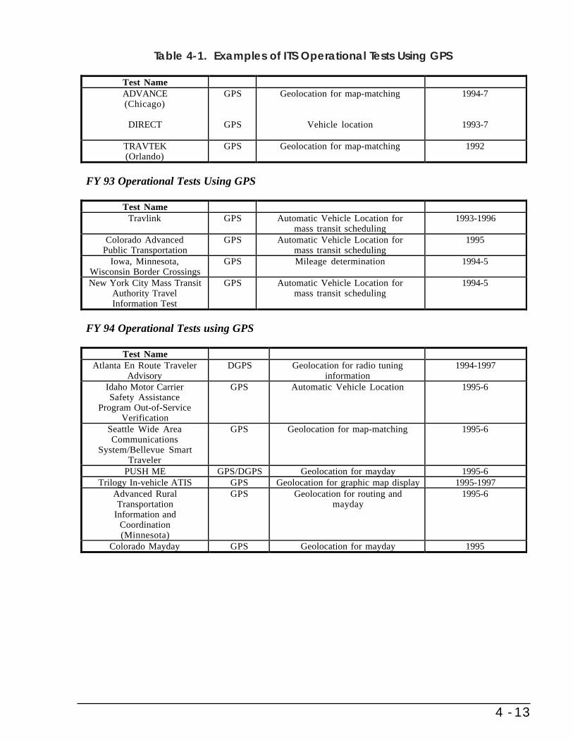
4 - 13
FHWA Tests funded prior to FY 93 using GPS
Test NameADVANCE(Chicago)
DIRECT
GPS
GPS
Geolocation for map-matching
Vehicle location
1994-7
1993-7
TRAVTEK(Orlando)
GPS Geolocation for map-matching 1992
FY 93 Operational Tests Using GPS
Test NameTravlink GPS Automatic Vehicle Location for
mass transit scheduling1993-1996
Colorado AdvancedPublic Transportation
GPS Automatic Vehicle Location formass transit scheduling
1995
Iowa, Minnesota,Wisconsin Border Crossings
GPS Mileage determination 1994-5
New York City Mass TransitAuthority TravelInformation Test
GPS Automatic Vehicle Location formass transit scheduling
1994-5
FY 94 Operational Tests using GPS
Test NameAtlanta En Route Traveler
AdvisoryDGPS Geolocation for radio tuning
information1994-1997
Idaho Motor CarrierSafety Assistance
Program Out-of-ServiceVerification
GPS Automatic Vehicle Location 1995-6
Seattle Wide AreaCommunications
System/Bellevue SmartTraveler
GPS Geolocation for map-matching 1995-6
PUSH ME GPS/DGPS Geolocation for mayday 1995-6Trilogy In-vehicle ATIS GPS Geolocation for graphic map display 1995-1997
Advanced RuralTransportation
Information andCoordination(Minnesota)
GPS Geolocation for routing andmayday
1995-6
Colorado Mayday GPS Geolocation for mayday 1995
Table 4-1. Examples of ITS Operational Tests Using GPS
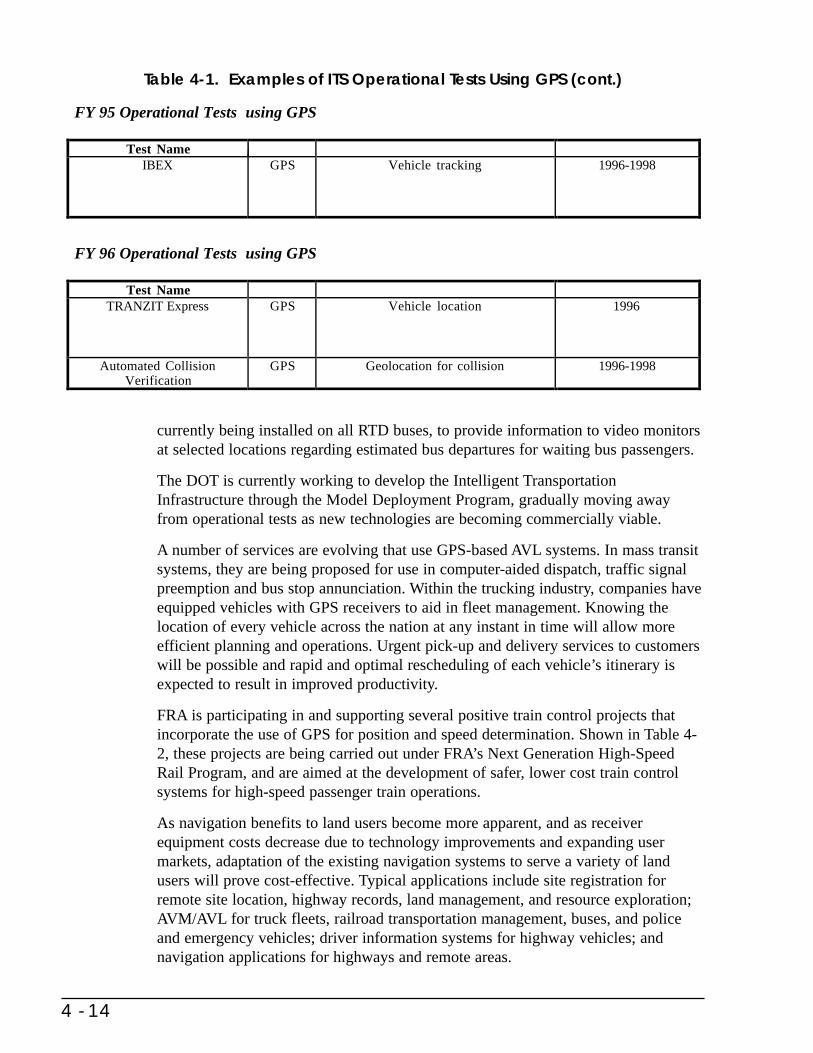
currently being installed on all RTD buses, to provide information to video monitorsat selected locations regarding estimated bus departures for waiting bus passengers.
The DOT is currently working to develop the Intelligent TransportationInfrastructure through the Model Deployment Program, gradually moving awayfrom operational tests as new technologies are becoming commercially viable.
A number of services are evolving that use GPS-based AVL systems. In mass transitsystems, they are being proposed for use in computer-aided dispatch, traffic signalpreemption and bus stop annunciation. Within the trucking industry, companies haveequipped vehicles with GPS receivers to aid in fleet management. Knowing thelocation of every vehicle across the nation at any instant in time will allow moreefficient planning and operations. Urgent pick-up and delivery services to customerswill be possible and rapid and optimal rescheduling of each vehicle’s itinerary isexpected to result in improved productivity.
FRA is participating in and supporting several positive train control projects thatincorporate the use of GPS for position and speed determination. Shown in Table 4-2, these projects are being carried out under FRA’s Next Generation High-SpeedRail Program, and are aimed at the development of safer, lower cost train controlsystems for high-speed passenger train operations.
As navigation benefits to land users become more apparent, and as receiverequipment costs decrease due to technology improvements and expanding usermarkets, adaptation of the existing navigation systems to serve a variety of landusers will prove cost-effective. Typical applications include site registration forremote site location, highway records, land management, and resource exploration;AVM/AVL for truck fleets, railroad transportation management, buses, and policeand emergency vehicles; driver information systems for highway vehicles; andnavigation applications for highways and remote areas.
4 - 14
FY 95 Operational Tests using GPS
Test NameIBEX GPS Vehicle tracking 1996-1998
FY 96 Operational Tests using GPS
Test NameTRANZIT Express GPS Vehicle location 1996
Automated CollisionVerification
GPS Geolocation for collision 1996-1998
Table 4-1. Examples of ITS Operational Tests Using GPS (cont.)

4.3 NASA R&D
NASA is conducting R&D in a number if GPS application areas in the space,aeronautics, and terrestrial environments. These efforts include:
Space Applications: The emphasis in the space applications R&D of GPS isprimarily on development of off-the-shelf GPS receivers that can be installed insatellites. These receivers will be capable of providing onboard navigation products,providing GPS time signals for distribution to spacecraft systems and instruments,providing necessary data for post-pass processing in support of science datacollection, and determining spacecraft attitude. Some receivers will send GPSobservables to the ground for processing of position information; however, the moreadvanced receivers will provide onboard autonomous position and navigation.
In addition to the direct use of GPS satellite information, NASA will be conductingresearch into the use of global GPS WAAS and the evolving GNSS. Initial work inthis area indicates that significant improvements will be achieved in real timedetermination of satellite position at the submeter level.
GPS will be installed on the Space Shuttle and the ISSA. The ISSA will employGPS receivers for acquiring precise time and determining satellite position andaltitude. The Shuttle applications will include use of GPS for on-orbit positiondetermination as well as a source of position data during Shuttle descent andlanding. Although critical missions will have alternate, backup means for positiondetermination, it is envisioned that some NASA satellites will be totally reliant onGPS for navigation, time, and altitude functions. This group of satellites will bemainly small, low-cost, single mission satellites. The use of GPS for time, onboardnavigation, and altitude determination will enable further automation of earth-orbiting satellites and will become a significant factor in reduction of satelliteconstruction and operations costs in the future.
During the next few years, NASA, in conjunction with DOD and the internationalcommunity, will be exploring the use of GPS at satellite altitudes extending togeosynchronous orbit.
4 - 15
Table 4-2. Positive Train Control Projects Using GPS
Project Sponsors Location
Positive Train Separation Union Pacific Railroad Seattle - PortlandSystem Burlington Northern Santa Fe Railway
Washington DOTOregon DOT
Incremental Train Control Michigan DOT Detroit - ChicagoSystem Amtrak
Advanced Train Control Illinois DOT Chicago - St. LouisSystem Amtrak
Union Pacific Railroad

NASA is also continuing to refine the post-pass processing techniques used tosupport precise analysis of scientific data requiring precise knowledge of spacecraftposition at data collection time.
Aeronautics Applications: NASA will continue to use GPS receivers aboard NASAaircraft for both aeronautics research and in support of airborne scientificobservations. There are numerous projects throughout NASA where GPS technologyis being developed for these purposes. Airborne GPS receivers have been used tosupport NASA scientific research in areas such as Airborne Synthetic ApertureRadar (AIRSAR) and in Greenland ice sheet thickness measurements, and it isanticipated that these uses of GPS will continue and expand.
Terrestrial Applications: NASA is supporting the continued development of theIGS. Areas of research include continued enhancement of the software used todetermine orbit ephemerides and techniques for improving measurement accuracy tothe 1 mm level.
4.4 NOAA R&D
NOAA performs GPS research and development aimed at (1) improved orbitdetermination, (2) improved determination of the vertical coordinate using GPS, and(3) development of models of error sources that can improve the accuracy attainableusing data from the CORS network of GPS reference stations. Some of the specificstudies being undertaken are: improved modeling of tidal deformations of the Earth;development of models of antenna phase center variation as a function of elevationangle of a satellite; development of models of station specific multipath errors;development of improved models of geoid height required to convert GPS derivedellipsoid heights to orthometric heights; and development of improvedcomputational models for determination of the vertical coordinate.
NOAA is also developing operational methods of using GPS derived totalprecipitable water vapor determinations in weather prediction and climate modelsand is investigating methods of improving the accuracy of the precipitable watervapor determinations. Finally, studies are underway to improve the methods used toposition and orient aircraft performing photogrammetry in support of nautical andaeronautical charting.
4.5 DOD R&D
GPS Security Program
The PDD announced that it was the U.S. intention to discontinue the use of GPSSelective Availability (SA) within a decade (2006) in a manner that allows adequatetime and resources for military forces to prepare for operations without SA.
The DOD has initiated a Navigation Warfare (NAVWAR) program that provides thewarfighter with the tools to effectively employ GPS as a force multiplier on the 21st
4 - 16
Century battlefield. The effort provides for the incorporation of advancedtechnologies to meet emerging mission requirements while countering theaterthreats. There are three elements to the NAVWAR effort: protection, prevention, andsustainment of civil use. Protection is the ability of U.S., Allied, and Coalition forcesto operate in a challenged electronic warfare environment. Prevention is the abilityto prevent an adversary's use of GPS technologies against us. There must be anintegration of protection and prevention technologies to ensure optimal use of GPSon the battlefield. In addition, civil use of GPS outside a theater of operations orarea of responsibility must not be adversely impacted by the military's exploitationof the electromagnetic spectrum. NAVWAR is designed to preserve civil user serviceby providing a regional or local protection and prevention capability, thus satisfyingthe U.S. commitment to provide SPS service on a worldwide basis.
This R&D effort will require periodic testing which may impact the civil use ofGPS. DOD and DOT are developing mechanisms to coordinate times and places fortesting, and to notify users in advance.
Multimode Receivers
Based on a continuing worldwide mission and a need to replace existing systems(particularly precision approach radars), the DOD has initiated a joint serviceprecision approach and landing system program. The portion of this program thathas common user application is the development of a multimode receiver forprecision landings.
Several contractors are developing multimode receivers for the DOD. To reduceaircraft integration cost, the prototype receivers are form, fit, and functionreplacements for current ILS receivers. The pilot sees the same display whetherusing MLS, ILS, or GPS (all generated from the same ILS-sized box).
The Air Force, at Hanscom AFB, MA, and the FAA, at their Tech Center nearAtlantic City, NJ, have proved the feasibility of such a multifunction, precisionlanding system receiver. The 113 approaches flown at Hanscom and the Tech Centerproved that the multimode receiver works with existing ground stations (ILS, MLS,and DGPS), and that the three landing systems are compatible on the same aircraft.These tests also showed that the prototype multimode receiver has the accuracy forCategory I performance, and provided operational insights for both civil certificationand military qualification. A production quality receiver with a 12 channel C/A-P/YGPS card could replace the standard ARN-108 military ILS receiver.
Improvements in Precise Time and Time Interval (PTTI)
Over the past several decades, developments in technology for all military electronicsystems have led to greater requirements for PTTI. Interoperability of systemsthroughout all the Services, as well as with NATO, requires accurate common time.Within the next decade, it is anticipated that requirements for PTTI at the 1 part in10 to the 15th per day (1ps) will exist. In order to prepare for this stringent
4 - 17

requirement, the U. S. Naval Observatory, as the provider of the DOD precisereference for time, has begun research and development efforts in advanced clockdesign and in clock analysis algorithms. In order to better disseminate the timereference, the USNO is developing a Distributed Master Clock System as well asinvestigating new techniques for time transfer. The Two-Way Time and FrequencySatellite Time Transfer System is currently under tests for very high precision users.
Recently, the importance of PTTI technology throughout DOD was recognized inthe Special Technology Area Review on Frequency Control Devices (STAR),February 1, 1996. It reported that frequency control device technology is of vitalimportance to the DOD since the accuracy and stability of frequency sources andclocks are key determinants of the performance of radar, C3I, navigation,surveillance, EW, missile guidance, and IFF systems.
The report continues with some R&D opportunities with potential for meeting futureDOD needs. These opportunities include development in high perfection quartz; newpiezoelectric materials; resonator theory, modeling and computer-aided design ofresonators and oscillators; processing and packaging of high stability resonators;microresonators and thin film resonators; low power, high, accuracy quartz clocks;low noise resonators and oscillators; smart clocks; miniature and high-performanceoptically pumped atomic clocks; and resonator based chemical, biological anduncooled infrared sensors.
4 - 18
Appendix ASystem Descriptions
This appendix addresses the characteristics, capabilities, and limitations of existingand proposed common-use radionavigation systems. The systems covered are:
• GPS • MLS
• GPS Augmentations • Aeronautical Nondirectional Beacons
• Loran-C • Maritime Radiobeacons
• Omega
• VOR, VOR/DME, and TACAN
• ILS
A.1 System Parameters
All of the systems described are defined in terms of system parameters whichdetermine the use and limitations of the individual navigation system’s signal-in-space. These parameters are:
• Signal Characteristics
• Accuracy
• Availability
• Coverage
• Reliability
• Fix Rate
A - 1
• Fix Dimensions
• System Capacity
• Ambiguity
• Integrity
A.1.1 Signal Characteristics
Signals-in-space are characterized by power levels, frequencies, signal formats, datarates, and any other information sufficient to completely define the means by whicha user derives navigational information.
A.1.2 Accuracy
In navigation, the accuracy of an estimated or measured position of a craft (vehicle,aircraft, or vessel) at a given time is the degree of conformance of that position withthe true position of the craft at that time. Since accuracy is a statistical measure ofperformance, a statement of the accuracy of a navigation system is meaninglessunless it includes a statement of the uncertainty in position which applies.
Statistical Measure of Accuracy
Navigation system errors generally follow a known error distribution. Therefore, theuncertainty in position can be expressed as the probability that the error will notexceed a certain amount. A thorough treatment of errors is complicated by the factthat the total error is comprised of errors caused by instability of the transmittedsignal, effects of weather and other physical changes in the propagation medium,errors in the receiving equipment, and errors introduced by the human navigator. Inspecifying or describing the accuracy of a system, the human errors usually areexcluded. Further complications arise because some navigation systems are linear(one-dimensional) while others provide two or three dimensions of position.
When specifying linear accuracy, or when it is necessary to specify requirements interms of orthogonal axes (e.g., along-track or cross-track), the 95 percent confidencelevel will be used. Vertical or bearing accuracies will be specified in one-dimensional terms (2 sigma), 95 percent confidence level.
When two-dimensional accuracies are used, the 2 drms (distance root mean squared)uncertainty estimate will be used. Two drms is twice the radial error drms. Theradial error is defined as the root-mean-square value of the distances from the truelocation point of the position fixes in a collection of measurements. It is often foundby first defining an arbitrarily-oriented set of perpendicular axes, with the origin atthe true location point. The variances around each axis are then found, summed, andthe square root computed. When the distribution of errors is elliptical, as it often isfor stationary, ground-based systems, these axes can be taken for convenience as themajor and minor axes of the error ellipse. Then the confidence level depends on the
A - 2
elongation of the error ellipse. As the error ellipse collapses to a line, the confidencelevel of the 2 drms measurement approaches 95 percent; as the error ellipse becomescircular, the confidence level approaches 98 percent. The GPS 2 drms accuracy willbe at 95 percent probability.
DOD specifies horizontal accuracy in terms of Circular Error Probable (CEP—theradius of a circle containing 50 percent of all possible fixes). For the FRP, theconversion of CEP to 2 drms has been accomplished by using 2.5 as the multiplier.
Types of Accuracy
Specifications of radionavigation system accuracy generally refer to one or more ofthe following definitions:
• Predictable accuracy: The accuracy of a radionavigation system’s positionsolution with respect to the charted solution. Both the position solution andthe chart must be based upon the same geodetic datum. (Note: Appendix Bdiscusses reference systems and the risks inherent in using charts inconjunction with radionavigation systems).
• Repeatable accuracy: The accuracy with which a user can return to a positionwhose coordinates have been measured at a previous time with the samenavigation system.
• Relative accuracy: The accuracy with which a user can measure positionrelative to that of another user of the same navigation system at the sametime.
A.1.3 Availability
The availability of a navigation system is the percentage of time that the services ofthe system are usable by the navigator. Availability is an indication of the ability ofthe system to provide usable service within the specified coverage area. Signalavailability is the percentage of time that navigational signals transmitted fromexternal sources are available for use. It is a function of both the physicalcharacteristics of the environment and the technical capabilities of the transmitterfacilities.
A.1.4 Coverage
The coverage provided by a radionavigation system is that surface area or spacevolume in which the signals are adequate to permit the navigator to determineposition to a specified level of accuracy. Coverage is influenced by system geometry,signal power levels, receiver sensitivity, atmospheric noise conditions, and otherfactors which affect signal availability.
A - 3

A.1.5 Reliability
The reliability of a navigation system is a function of the frequency with whichfailures occur within the system. It is the probability that a system will perform itsfunction within defined performance limits for a specified period of time undergiven operating conditions. Formally, reliability is one minus the probability ofsystem failure.
A.1.6 Fix Rate
The fix rate is defined as the number of independent position fixes or data pointsavailable from the system per unit time.
A.1.7 Fix Dimensions
This characteristic defines whether the navigation system provides a linear, one-dimensional line-of-position, or a two-or three-dimensional position fix. The abilityof the system to derive a fourth dimension (e.g., time) from the navigational signalsis also included.
A.1.8 System Capacity
System capacity is the number of users that a system can accommodatesimultaneously.
A.1.9 Ambiguity
System ambiguity exists when the navigation system identifies two or more possiblepositions of the vehicle, with the same set of measurements, with no indication ofwhich is the most nearly correct position. The potential for system ambiguitiesshould be identified along with provision for users to identify and resolve them.
A.1.10 Integrity
Integrity is the ability of a system to provide timely warnings to users when thesystem should not be used for navigation.
A.2 System Descriptions
This section describes the characteristics of those individual radionavigation systemscurrently in use or under development. These systems are described in terms of theparameters previously defined in Section A.1. All of the systems used for civilnavigation are discussed. The systems which are used exclusively to meet the specialapplications of DOD are discussed in the CJCS MNP.
A - 4

A.2.1 GPS
GPS is a space-based radionavigation system which is operated for the Governmentof the United States by the U.S. Air Force. GPS was originally developed as amilitary force enhancement system and will continue to play this role; however, GPSalso has significant potential to benefit the civil community in an increasingly largenumber and variety of applications. In an effort to make GPS service available to thegreatest number of users while ensuring that national security interests of the UnitedStates are protected, two GPS services are provided. The Precise Positioning Service(PPS) provides full system accuracy to authorized users. The Standard PositioningService (SPS) is designed to provide accurate positioning to all users throughout theworld. The GPS has three major segments: space, control, and user.
The GPS Space Segment is composed of 24 satellites in six orbital planes. Thesatellites operate in circular 20,200 km (10,900 nm) orbits at an inclination angle of55 degrees and with a 12-hour period. The spacing of satellites in orbit are arrangedso that a minimum of 5 satellites are in view to users worldwide, with a PositionDilution of Precision (PDOP) of six or less.
The GPS Control Segment has five monitor stations and three ground antennas withuplink capabilities. The monitor stations use a GPS receiver to passively track allsatellites in view and accumulate ranging data from the satellite signals. Theinformation from the monitor stations is processed at the Master Control Station(MCS) to determine satellite clock and orbit states and to update the navigationmessage of each satellite. This updated information is transmitted to the satellites viathe ground antennas, which are also used for transmitting and receiving health andcontrol information.
The GPS User Segment consists of a variety of configurations and integrationarchitectures that include an antenna and receiver-processor to receive and computenavigation solutions to provide positioning, velocity, and precise timing to the user.
The characteristics of GPS are summarized in Table A-1.
A. Signal Characteristics
Each satellite transmits three separate spectrum signals on two L-band frequencies,L1 (1575.42 MHz) and L2 (1227.6 MHz). L1 carries a Precise P (Y) Pseudo-Random Noise (PRN) code and a Coarse/Acquisition (C/A) PRN code; L2 carriesthe P(Y) PRN code. (The Precise code is denoted as P(Y) to identify that this PRNcode can be operated in either a clear unencrypted “P” or an encrypted “Y” codeconfiguration.) Both PRN codes carried on the L1 and L2 frequencies are phase-synchronized to the satellite clock and modulated (using modulo two addition) witha common 50 Hz navigation data message.
The SPS signal received by the user is a spread spectrum signal centered on L1 witha 2.046 MHz bandwidth. Minimum SPS received power is specified as -160.0 dBW.The navigation data contained in the signal is composed of satellite clock and
A - 5
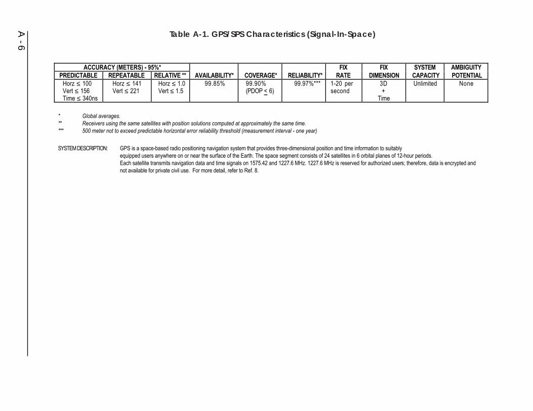
A - 6
ACCURACY (METERS) - 95%* FIX FIX SYSTEM AMBIGUITYPREDICTABLE REPEATABLE RELATIVE ** AVAILABILITY* COVERAGE* RELIABILITY* RATE DIMENSION CAPACITY POTENTIAL
Horz ≤ 100Vert ≤ 156Time ≤ 340ns
Horz ≤ 141Vert ≤ 221
Horz ≤ 1.0Vert ≤ 1.5
99.85% 99.90%(PDOP < 6)
99.97%*** 1-20 persecond
3D+
Time
Unlimited None
*� Global averages.**� Receivers using the same satellites with position solutions computed at approximately the same time.***� 500 meter not to exceed predictable horizontal error reliability threshold (measurement interval - one year)
SYSTEM DESCRIPTION: GPS is a space-based radio positioning navigation system that provides three-dimensional position and time information to suitably equipped users anywhere on or near the surface of the Earth. The space segment consists of 24 satellites in 6 orbital planes of 12-hour periods. Each satellite transmits navigation data and time signals on 1575.42 and 1227.6 MHz. 1227.6 MHz is reserved for authorized users; therefore, data is encrypted and not available for private civil use. For more detail, refer to Ref. 8.
Table A-1. GPS/SPS Characteristics (Signal-In-Space)

ephemeris data for the transmitting satellite plus GPS constellation almanac data,GPS to UTC time offset information, and ionospheric propagation delay correctionparameters for single frequency users. The entire navigation message repeats every12.5 minutes. Within this 12.5-minute repeat cycle, satellite clock and ephemerisdata for the transmitting satellite is sent 25 separate times so it repeats every 30seconds. As long as a satellite indicates a healthy status, a receiver can continue tooperate using this data for the validity period of the data (up to 4 or 6 hours). Thereceiver will update this data whenever the satellite and ephemeris information isupdated - nominally once every 2 hours.
The concept of GPS position determination is based on the intersection of fourseparate vectors each with a known origin and a known magnitude. Vector originsfor each satellite are computed based on satellite ephemeris. Vector magnitudes arecalculated based on signal propagation time delay as measured from the transmittingsatellite’s PRN code phase delay. Given that the satellite signal travels at nearly thespeed of light and taking into account delays and adjustment factors such asionospheric propagation delays and earth rotation factors, the receiver performsranging measurements between the individual satellite and the user by dividing thesatellite signal propagation time by the speed of light.
B. Accuracy
GPS provides two services for position determination, SPS and PPS. Accuracy of aGPS fix varies with the capability of the user equipment.
1. Standard Positioning Service (SPS)
SPS is the standard specified level of positioning and timing accuracy that isavailable, without restrictions, to any user on a continuous worldwide basis. SPSprovides a predictable positioning accuracy of 100 meters (95 percent) horizontallyand 156 meters (95 percent) vertically and time transfer accuracy to UTC within 340nanoseconds (95 percent). Decisions to change operational modes of GPS to includedegrading GPS accuracy to civil users will be made by the NCA.
2. Precise Positioning Service (PPS)
PPS is the most accurate direct positioning, velocity, and timing informationcontinuously available, worldwide, from the basic GPS. This service is limited bythe DOD to users who are specifically authorized access. P(Y) code capable userequipment provides a predictable positioning accuracy of at least 22 meters (95percent) horizontally and 27.7 meters vertically and time transfer accuracy to UTCwithin 200 nanoseconds (95 percent).
C. Availability
Provided there is coverage as defined below, SPS will be available at least 99.85percent of the time.
A - 7
D. Coverage
GPS coverage is worldwide. The probability that 4 or more GPS satellites are inview anywhere on or near the earth (over any 24-hour period) with a PDOP of 6 orless, and with at least a 5 deg mask angle, is at least 99.9 percent.
E. Reliability
If the conditions on coverage and service availability are met, the probability that thehorizontal positioning error will not exceed 500 meters at any time is at least 99.7percent.
F. Fix Rate
The fix rate is essentially continuous, but the need for receiver processing to retrievethe spread-spectrum signal from the noise results in an actual users fix rate of 1-20per second. Actual time to a first fix depends on user equipment capability andinitialization with current satellite almanac data.
G. Fix Dimensions
GPS provides three-dimensional positioning and time when four or more satellitesare available and two-dimensional positioning when only three satellites areavailable.
H. System Capacity
The capacity is unlimited.
I. Ambiguity
There is no ambiguity.
J. Integrity
DOD GPS receivers use the information contained in the navigation and healthmessages, as well as self-contained satellite geometry software programs andinternal navigation solution convergence monitors, to compute an estimated figure ofmerit. This number is continuously displayed to the operator, indicating theestimated overall confidence level of the position information. The figure of meritdoes not satisfy civil aviation requirements.
A.2.2 Augmentations to GPS
GPS may exhibit variances from a predicted grid established for navigation,charting, or derivation of guidance information. This variance may be caused by
A - 8
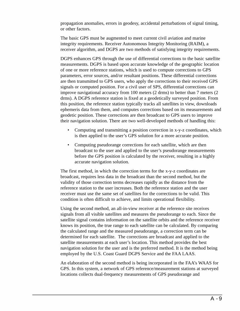
propagation anomalies, errors in geodesy, accidental perturbations of signal timing,or other factors.
The basic GPS must be augmented to meet current civil aviation and marineintegrity requirements. Receiver Autonomous Integrity Monitoring (RAIM), areceiver algorithm, and DGPS are two methods of satisfying integrity requirements.
DGPS enhances GPS through the use of differential corrections to the basic satellitemeasurements. DGPS is based upon accurate knowledge of the geographic locationof one or more reference stations, which is used to compute corrections to GPSparameters, error sources, and/or resultant positions. These differential correctionsare then transmitted to GPS users, who apply the corrections to their received GPSsignals or computed position. For a civil user of SPS, differential corrections canimprove navigational accuracy from 100 meters (2 drms) to better than 7 meters (2drms). A DGPS reference station is fixed at a geodetically surveyed position. Fromthis position, the reference station typically tracks all satellites in view, downloadsephemeris data from them, and computes corrections based on its measurements andgeodetic position. These corrections are then broadcast to GPS users to improvetheir navigation solution. There are two well-developed methods of handling this:
• Computing and transmitting a position correction in x-y-z coordinates, whichis then applied to the user’s GPS solution for a more accurate position.
• Computing pseudorange corrections for each satellite, which are thenbroadcast to the user and applied to the user’s pseudorange measurementsbefore the GPS position is calculated by the receiver, resulting in a highlyaccurate navigation solution.
The first method, in which the correction terms for the x-y-z coordinates arebroadcast, requires less data in the broadcast than the second method, but thevalidity of those correction terms decreases rapidly as the distance from thereference station to the user increases. Both the reference station and the userreceiver must use the same set of satellites for the corrections to be valid. Thiscondition is often difficult to achieve, and limits operational flexibility.
Using the second method, an all-in-view receiver at the reference site receivessignals from all visible satellites and measures the pseudorange to each. Since thesatellite signal contains information on the satellite orbits and the reference receiverknows its position, the true range to each satellite can be calculated. By comparingthe calculated range and the measured pseudorange, a correction term can bedetermined for each satellite. The corrections are broadcast and applied to thesatellite measurements at each user’s location. This method provides the bestnavigation solution for the user and is the preferred method. It is the method beingemployed by the U.S. Coast Guard DGPS Service and the FAA LAAS.
An elaboration of the second method is being incorporated in the FAA’s WAAS forGPS. In this system, a network of GPS reference/measurement stations at surveyedlocations collects dual-frequency measurements of GPS pseudorange and
A - 9
pseudorange rate for all spacecraft in view, along with local meteorologicalconditions. These data can be processed to yield highly accurate ephemeris,ionospheric and tropospheric calibration maps, and DGPS corrections for thebroadcast spacecraft ephemeris and clock offsets (including the effects of SelectiveAvailability (SA). In the WAAS, these GPS corrections and system integritymessages will be relayed to civil users via a dedicated package on geostationarysatellites. This relay technique will also support the delivery of an additional rangingsignal, thereby increasing overall navigation system availability.
Non-navigation users of GPS who require few-centimeter accuracy or employ postprocessing to achieve few-decimeter to few-meter accuracy often employaugmentation somewhat differently from navigation users. For post processingapplications using C/A code range, the actual observations from a reference station(rather than correctors) are provided to users. The users then compute correctors intheir reduction software. Surveyors and other users who need subcentimeter to few-centimeter accuracy in positioning from post-processing use two-frequency (L1 andL2) carrier phase observations from reference stations, rather than range data. TheCORS system is designed to meet the needs of both of the above types of theseusers.
Real time carrier phase differential positioning is increasingly employed by non-navigation users. Currently, this requires a GPS reference station within a few tensof kilometers of a user. In many cases, users are implementing their own referencestations, which they operate only for the duration of a specific project. Permanentreference stations to support real time carrier phase positioning by multiple users iscurrently provided in the U.S. primarily by private industry. Some state and localgovernment groups are moving toward providing such reference stations. Othercountries are establishing nationwide, real time, carrier phase reference stationnetworks at the national government level.
With the advent of commercially available combined GPS/GLONASS receivers,non-navigation users will begin to augment GPS with reference stations that providedifferential GPS and GLONASS. This will occur most rapidly where users operatein locations such as urban canyons and heavily forested areas where sufficient GPSsatellites are not always in view to adequately support positioning.
A worldwide network of GPS reference stations is needed for geodetic referenceframe, geophysical, and meteorological applications which require carrier phase datato achieve centimeter level accuracy on a regional to global basis. Such a network iscurrently operated by the IGS and provides the required centimeter-accuracyreference frame and subdecimeter orbits. At present, this worldwide IGS referencenetwork supports only post-processing applications. However, the IGS is movingtoward near-real time to real time provision of information to support suchapplications as seismic monitoring and inclusion of water vapor information intoshort term weather prediction. Because this near-real-time and real-time informationwould be used by fixed facilities rather than moving platforms, it may be providedto users by telephone or similar communications links rather than by broadcast.
A - 10

A.2.2.1 Maritime DGPS
Figure A-1 shows the USCG DGPS architecture using pseudorange corrections. Thereference station’s and the mariner’s pseudorange calculations are stronglycorrelated. Pseudorange corrections computed by the reference station, whentransmitted to the mariner in a timely manner, can be directly applied to themariner’s pseudorange computation to dramatically increase the resultant accuracyof the pseudorange measurement before it is applied within the mariner’s navigationsolution. The USCG DGPS fielded sites are achieving accuracies on the order of 1meter. Figure A-1 and the following discussion describe the characteristics of themaritime DGPS system.
A. Signal Characteristics
The datalinks for DGPS corrections are radiobeacons which have been converted toaccept MSK modulation. This conversion to single-carrier operation removes theMorse tone identifier, thus removing compliance with IMO standards for marineradiobeacons. Real time differential GPS corrections are provided in the RadioTechnical Commission for Maritime Services Special Committee 104 (RTCM SC-
A - 11
CONTROL STATION
REFERENCE STATION
BROADCAST SITE AND
INTEGRITY MONITOR
Corrections Sent to Mariners
GPSSatellite
Pseudorange A Pseudorange B
PACKET
COMMUNICATION
NETWORK
PACKET NETWORK CONNECTIONSWITH OTHER BROADCAST SITES
•••
Figure A-1. USCG DGPS Navigation Service Architecture

104) format and broadcast to all users capable of receiving the signals. The USCGdoes not use data encryption. Radiobeacons were chosen because of existinginfrastructure, compatibility with the useful range of DGPS corrections, internationalradio conventions, international acceptance, commercial availability of equipment,and highly successful field tests.
The USCG’s DGPS system will broadcast corrections to the user in the RTCM SC-104 format. The RTCM has defined data messages and an interface between theDGPS receiver and the data link receiver. The USCG DGPS Broadcast Standard(Commandant Instruction M16577.1) should be consulted for detailed informationon DGPS broadcasts.
B. Accuracy
The accuracy of the USCG’s DGPS service is expected to be better than 10 meters(2 drms) in all approaches to major U.S. harbors. Fielded operations are nowachieving accuracies on the order of 1 meter.
C. Availability
Availability will be 99.9 percent in selected waterways with more stringent VTSrequirements and at least 99.7 percent in other parts of the coverage area.
D. Coverage
Figure A-2 shows the approximate coverage of the USCG’s maritime DGPS system.Per the USCG’s DGPS Broadcast Standard (COMDTINST M16577.1), the USCGsystem is designed to provide complete coastal DGPS coverage of the continentalU.S. to a minimum range of 20 nm from shore and to selected portions of Hawaii,coastal Alaska, Puerto Rico, and major inland rivers.
E. Reliability
The number of outages per site will be less than 500 in one million hours ofoperation with a time to alarm of less than five seconds.
F. Fix Rate
The DGPS reference station computes corrections at least once per second. Due tothe transmission time, users will receive updated corrections on an average of everyfive seconds for beacons transmitting at 100 bps and every 2.5 seconds for beaconstransmitting at 200 bps.
G. Fix Dimensions
Through the application of pseudorange corrections, maritime differential GPSprovides three-dimensional positioning and velocity fixes.
A - 12
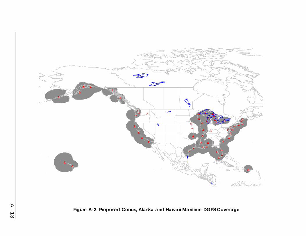
A - 13
Figure A-2. Proposed Conus, Alaska and Hawaii Maritime DGPS Coverage

H. System Capacity
Unlimited.
I. Ambiguity
None.
J. Integrity
DGPS system integrity is provided through an on-site integrity monitor and 24-houroperations at a DGPS control center. Users will be notified of an out-of-tolerancecondition within five seconds.
In addition to providing a highly accurate navigational signal, DGPS also provides acontinuous integrity check on satellite health. System integrity is a real concern withGPS. With the design of the ground segment of GPS, a satellite can be transmittingan unhealthy signal for 2 to 6 hours before it can be detected and corrected by theMaster Control Station or before users can be warned not to use the signal. Throughits use of continuous, real time messages, the DGPS system can often extend the useof unhealthy GPS satellites by providing accurate corrections, or will direct thenavigator to ignore an erroneous GPS signal.
A.2.2.2 Aeronautical GPS Wide Area Augmentation System (WAAS)
The WAAS will be a safety-critical system consisting of the equipment and softwarewhich augments the DOD-provided GPS Standard Positioning Service (see FigureA-3). It will provide a signal-in-space to WAAS users with the specific goal ofsupporting aviation navigation for the en route through Category I precisionapproach phases of flight. The signal-in-space will provide three services: (1)integrity data on GPS and GEO satellites, (2) wide area differential corrections forGPS satellites, and (3) an additional ranging capability.
The GPS satellites’ data is to be received and processed at widely dispersed sites,referred to as Wide-area Reference Stations (WRS). These data are forwarded todata processing sites, referred to as Wide-area Master Stations (WMS), whichprocess the data to determine the integrity, differential corrections, residual errors,and ionospheric information for each monitored satellite and generate GEO satellitenavigation parameters. This information is to be sent to a Ground Earth Station(GES) and uplinked along with the GEO navigation message to GEO satellites.These GEO satellites will then downlink this data on the GPS Link I (LI) frequencywith a modulation similar to that used by GPS.
In addition to providing GPS integrity, the WAAS will verify its own integrity andtake any necessary action to ensure that the system meets the WAAS performancerequirements. The WAAS also has a system operations and maintenance functionthat provides information to FAA Airway Facilities NAS personnel.
A - 14
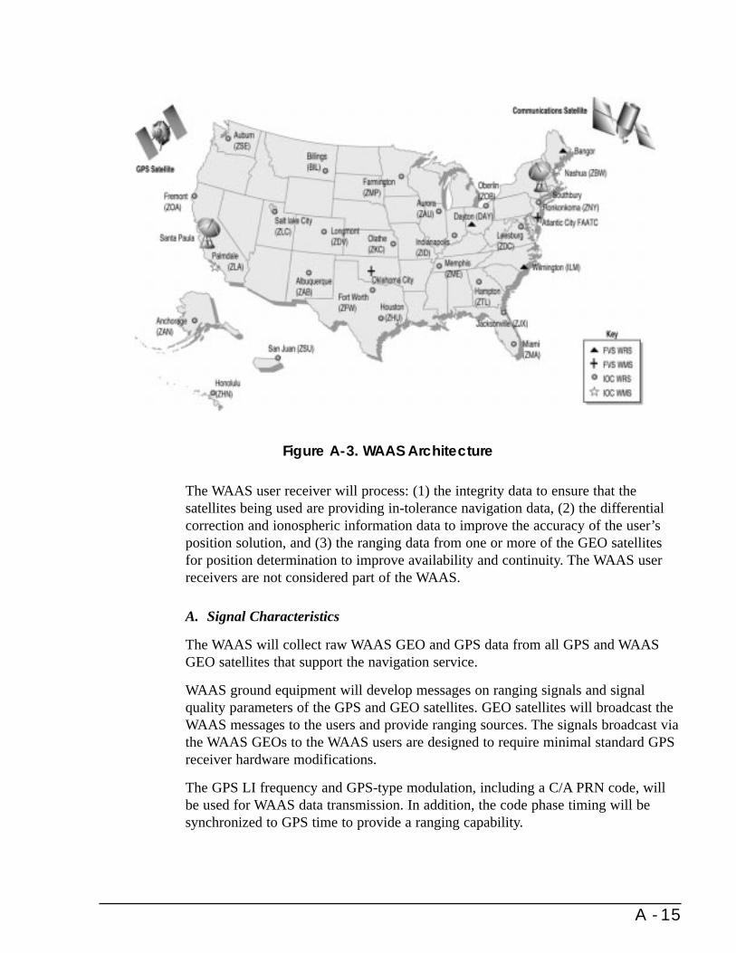
The WAAS user receiver will process: (1) the integrity data to ensure that thesatellites being used are providing in-tolerance navigation data, (2) the differentialcorrection and ionospheric information data to improve the accuracy of the user’sposition solution, and (3) the ranging data from one or more of the GEO satellitesfor position determination to improve availability and continuity. The WAAS userreceivers are not considered part of the WAAS.
A. Signal Characteristics
The WAAS will collect raw WAAS GEO and GPS data from all GPS and WAASGEO satellites that support the navigation service.
WAAS ground equipment will develop messages on ranging signals and signalquality parameters of the GPS and GEO satellites. GEO satellites will broadcast theWAAS messages to the users and provide ranging sources. The signals broadcast viathe WAAS GEOs to the WAAS users are designed to require minimal standard GPSreceiver hardware modifications.
The GPS LI frequency and GPS-type modulation, including a C/A PRN code, willbe used for WAAS data transmission. In addition, the code phase timing will besynchronized to GPS time to provide a ranging capability.
A - 15
Figure A-3. WAAS Architecture

B. Accuracy
Accuracies for the WAAS are currently based on aviation requirements. For the enroute through nonprecision approach phases of flight, a horizontal accuracy of 100meters 95 percent of the time is guaranteed with the requisite availability andintegrity levels to support operations in the NAS. For the Category I precisionapproach phase of flight, horizontal and vertical accuracies are guaranteed at 7.6meters 95 percent of the time.
C. Availability
The WAAS availability for the en route through nonprecision approach phases offlight is at least 0.99999. For the precision approach phase of flight, the availabilityis at least 0.999.
D. Coverage
The WAAS full service volume is defined from the Category I decision height up to100,000 feet for the airspace of the 48 contiguous states, Hawaii, Puerto Rico, andAlaska (except for the Alaskan peninsula west of longitude 160 degrees West oroutside of the GEO satellite broadcast area).
E. Reliability
The WAAS will provide sufficient reliability and redundancy to meet the overallNAS requirements with no single point of failure. The overall reliability of theWAAS signal-in-space will approach 100 percent.
F. Fix Rate
This system provides a virtually continuous position update.
G. Fix Dimensions
The WAAS provides three-dimensional position fixing and highly-accurate timinginformation.
H. System Capacity
The user capacity is unlimited.
I. Ambiguity
The system provides no ambiguity of position fixing information.
A - 16

J. Integrity
Integrity augmentation of the GPS SPS by the WAAS is a required capability that isboth an operational characteristic and a technical characteristic. The required systemperformance levels for the integrity augmentation are the levels necessary so thatGPS/WAAS can be used for all phases of flight.
Integrity for the WAAS is specified by three parameters: probability of hazardouslymisleading information (PHMI), time to alarm, and the alarm limit. For the en routethrough nonprecision approach phases of flight, the performance values are:
PHMI 10-7 per hourTime to Alarm 8 secondsAlarm Limit Protection limits specified
for each phase of flight
For the precision approach phase of flight, integrity performance values are:
PHMI 4 x 10⁻⁸ per approachTime to Alarm 5.2 secondsAlarm Limit As required for Category I operation
The WAAS will provide the information such that the user equipment can determinethe integrity to these levels.
A.2.3 Loran-C
Loran-C was developed to provide DOD with a radionavigation capability havinglonger range and much greater accuracy than its predecessor, Loran-A. It wassubsequently selected as the Federally provided radionavigation system for civilmarine use in the U.S. coastal areas.
A. Signal Characteristics
Loran-C is a pulsed, hyperbolic system operating in the 90 to 110 kHz frequencyband. The system is based upon measurement of the difference in time of arrival ofpulses of radio frequency (RF) energy radiated by a chain of synchronizedtransmitters which are separated by hundreds of miles. The measurements of timedifference (TD) are made by a receiver which achieves high accuracy by comparinga zero crossing of a specified RF cycle within the pulses transmitted by master andsecondary stations within a chain. Making this signal comparison early in the groundwave pulse assures that the measurement is made before the arrival of thecorresponding sky waves. Precise control over the pulse shape ensures that theproper comparison point can be identified by the receiver. To aid in preventing skywaves from affecting TD measurements, the phase of the 100 kHz carrier of some ofthe pulses is changed in a predetermined pattern. Envelope matching of the signals isalso possible but cannot provide the advantage of cycle comparison in obtaining thefull system accuracy. The characteristics of Loran-C are summarized in Table A-2.
A - 17

A - 18
ACCURACY (2 drms) FIX FIX SYSTEM AMBIGUITYPREDICTABLE REPEATABLE AVAILABILITY COVERAGE RELIABILITY RATE DIMENSIONS CAPACITY POTENTIAL
0.25nm(460m)1:3 SNR
60-300 ft.(18-90m)
99.7%U.S. coastal areas,continental U.S.,
selectedoverseas areas
99.7%* 1fix/sec.
2D Unlimited Yes, easilyresolved
*� Triad reliability.
SYSTEM DESCRIPTION: Loran-C is a Low Frequency (LF) 100kHz hyperbolic radionavigation system. The receiver computes lines of position (LOP) based on the time of arrivaldifference between two time-synchronized transmitting stations of a chain. Three stations are required (master and two secondaries) to obtain a positionix in the normal mode of operation. Loran-C can be used in the Rho-Rho mode and accurate position data can be obtained with only two stations. Rho-Rho requires that the user platform have a precise clock.
f
Table A-2. Loran-C System Characteristics (Signal-In-Space)

B. Accuracy
Within the published coverage area, Loran-C provides the user who employs anadequate receiver with predictable accuracy of 0.25 nm (2 drms) or better. Therepeatable accuracy of Loran-C is usually between 18 and 90 meters. Accuracy isdependent upon the Geometric Dilution of Precision (GDOP) factors at the user’slocation within the coverage area.
Loran-C navigation is predominantly accomplished using the ground wave signal.Sky wave navigation is feasible, but with considerable loss in accuracy. Groundwaves and to some degree sky waves may be used for measuring time and timeintervals. Loran-C was originally designed to be a hyperbolic navigation system.However, with the advent of the highly stable frequency standards, Loran-C can alsobe used in the range-range (rho-rho) mode of navigation. This is accomplished by acomparison of the received signal phase to a known time reference to determinepropagation time and, therefore, range from the stations. It can be used in situationswhere the user is within reception range of individual stations, but beyond thehyperbolic coverage area. Because the position solution of GPS provides precisetime, the interpretable use of rho-rho Loran-C with GPS appears to have merit.
By monitoring Loran-C signals at a fixed site, the receiver TD can be compared witha computed TD for the known location of the site. A correction for the area can thenbe broadcast to users. This technique (called differential Loran-C), whereby realtime corrections are applied to Loran-C TD readings, provides improved accuracy.Although this can improve Loran-C’s absolute accuracy features, no investment inthis approach to enhancing Loran-C’s performance is anticipated by the FederalGovernment.
Loran-C receivers are available at a relatively low cost and achieve the 0.25 nm (2drms) accuracy that Loran-C provides at the limits of the coverage area. A modernLoran-C receiver automatically acquires and tracks the Loran-C signal and is usefulto the limits of the specified Loran-C coverage areas.
C. Availability
The Loran-C transmitting equipment is very reliable. Redundant transmittingequipment is used to reduce system downtime. Loran-C transmitting station signalavailability is greater than 99.9 percent, providing 99.7 percent triad availability.
D. Coverage
The Loran-C system has been expanded over the years to meet the requirements forcoverage of the U.S. coastal waters and the conterminous 48 states, the Great Lakes,the Gulf of Alaska, the Aleutians, and into the Bering Sea. Current Loran-Ccoverage is shown in Figure A-4.
Expansion of the Loran-C system into the Caribbean Sea, the North Slope of Alaska,and Eastern Hawaii has been investigated. Studies have shown, however, that the
A - 19

A - 20
Figure A-4. Coverage Provided by U.S. Operated or Supported Loran-C Stations
benefit/cost ratio was insufficient to justify expansion of Loran-C into any of theseareas.
E. Reliability
Loran-C stations are constantly monitored. The accuracy of system timing ismaintained to half the system tolerance. Stations which exceed the system toleranceare “blinked.” Blink is the on-off pattern of the first two pulses of the secondarysignal indicating that a baseline is unusable. System tolerance within the U.S. is+100 nanoseconds of the calibrated control value. Individual station reliabilitynormally exceeds 99.9 percent, resulting in triad availability exceeding 99.7 percent.
F. Fix Rate
The fix rate available from Loran-C ranges from 10 to 20 fixes per second, based onthe Group Repetition Interval. Receiver processing in noise results in typically 1 fixper second.
G. Fix Dimensions
Loran-C will furnish two or more lines of position (LOPs) to provide a two-dimensional fix.
H. System Capacity
An unlimited number of receivers may use Loran-C simultaneously.
I. Ambiguity
As with all hyperbolic systems, theoretically, the LOPs may cross at more than oneposition on the earth. However, because of the design of the coverage area, theambiguous fix is at a great distance from the desired fix and is easily resolved.
J. Integrity
Loran-C stations are constantly monitored to detect signal abnormalities whichwould render the system unusable for navigation purposes. The secondary stations“blink” to notify the user that a master-secondary pair is unusable. Blink beginsimmediately upon detection of an abnormality. The USCG and the FAA are alsodeveloping automatic blink equipment and a concept of operations based on factorsconsistent with aviation use. If automatic blink equipment is installed in the NAS,secondary blink would be initiated within ten seconds of a timing abnormality and inthe case of a Master station, the signal will be taken off-air until the problem iscorrected and all secondaries are blinking.
A - 21

A.2.4 Omega
The Omega system initially was proposed to meet a DOD need for worldwidegeneral en route navigation but has now evolved into a system used primarily by thecivil community. The system is comprised of eight continuous wave (CW)transmitting stations situated throughout the world. Omega information can beobtained via the USCG Navigation Information Service. The characteristics ofOmega are summarized on Table A-3.
A. Signal Characteristics
Omega utilizes CW phase comparison of signal transmission from pairs of stations.The stations transmit time-shared signals on four frequencies, in the following order:10.2 kHz, 11.33 kHz, 13.6 kHz, and 11.05 kHz. In addition to these commonfrequencies, each station transmits a unique frequency to aid station identificationand to enhance receiver performance.
B. Accuracy
The inherent accuracy of the Omega system is limited by the accuracy of thepropagation corrections that must be applied to the individual receiver readings. Thecorrections may be in the form of predictions from tables which can be applied tomanual receivers or may be stored in memory and applied automatically incomputerized receivers. The system was designed to provide a predictable accuracyof 2 to 4 nm (2 drms). That accuracy depends on location, station pairs used, time ofday, and validity of the propagation corrections.
Propagation correction tables and formulas are based on theoretical modelscalibrated to fit worldwide monitor data taken over long periods. A number ofpermanent monitors are maintained to assess the system accuracy on a long-termbasis. The system currently provides coverage over most of the Earth. The specificaccuracy attained depends on the type of equipment used as well as the time of dayand the location of the user. In most cases, the accuracies attained are consistentwith the 2 to 4 nm system design goal and in some cases much better accuracy isreported. A validation program conducted by the USCG indicated that the Omegasystem meets its design goal of 2 to 4 nm accuracy.
C. Availability
Exclusive of infrequent periods of scheduled off-air time for maintenance, Omegaavailability is greater than 99 percent per year for each station and 95 percent forthree stations. Annual system availability has been greater than 97 percent withscheduled off-air time included.
D. Coverage
Omega provides essentially worldwide coverage.
A - 22

A - 23
ACCURACY (2 drms) FIX FIX SYSTEM AMBIGUITYPREDICTABLE REPEATABLE RELATIVE* AVAILABILITY COVERAGE RELIABILITY RATE DIMENSION CAPACITY POTENTIAL
2-4 nm(3.7-7.4km)
2-4nm(3.7-7.4km)
0.25-0.5nm(463-926m)
99+% Worldwidecontinuous
97%*1 fix to
every 10seconds
2D UnlimitedRequires
knowledge to+36nm**
*� Three station joint signal availability. **� Three frequency receiver (10.2, 11.33, 13.6kHz).
SYSTEM DESCRIPTION: Omega is a Very Low Frequency (VLF) 10.2 - 13.6kHz hyperbolic radionavigation system. There are eight transmitting stations. Position information is obtained by measuring relative phase difference of received Omega signals. The system is multinational, operated by seven nations, with day-to-day operational controlexercised by the U.S. Coast Guard.
Table A-3. Omega System Characteristics (Signal-In-Space)
E. Reliability
Omega system design requirements for reliability called for 99 percent single stationavailability and 95 percent three-station joint signal availability. Three-station jointsignal availability exceeds 97 percent, including both emergency shutdowns andscheduled off-air periods.
F. Fix Rate
Omega provides independent position fixes once every ten seconds.
G. Fix Dimensions
Omega will furnish two or more LOPs to provide a two-dimensional fix.
H. System Capacity
An unlimited number of receivers may be used simultaneously.
I. Ambiguity
In this CW system, ambiguous LOPs occur since there is no means to identifyparticular points of constant phase difference which recur throughout the coveragearea. The area between lines of zero phase difference are termed “lanes.” Single-frequency receivers use the 10.2 kHz signals whose lane width is about eightnautical miles on the baseline between stations. Multiple-frequency receivers extendthe lane width, for the purpose of resolving lane ambiguity. Lane widths ofapproximately 288 nm along the baseline can be generated with a four-frequencyreceiver. Because of the lane ambiguity, a receiver must be preset to a knownlocation at the start of a voyage. The accuracy of that position must be known withsufficient accuracy to be within the lane that the receiver is capable of generating(i.e., 4 nm for a single-frequency receiver or approximately 144 nm for a four-frequency receiver). Once set to a known location, the Omega receiver counts thenumber of lanes it crosses in the course of a voyage. This lane count is subject toerrors which may be introduced by an interruption of power to the receiver, changesin propagation conditions near local sunset and sunrise, and other factors. To use thesingle frequency Omega receiver effectively for navigation, it is essential that a DRplot or similar means be carefully maintained and the Omega positions compared toit periodically so that any lane ambiguities can be detected and corrected.
The accuracy of an Omega phase-difference measurement is independent of theelapsed time or distance since the last update. Unless the Omega position is verifiedoccasionally by comparison to a fix obtained with another navigation system or byperiodic comparison to a carefully maintained plot, the chance of an error in theOmega lane count increases with time and distance. These errors are reduced inmultiple frequency receivers since they are capable of developing larger lane widthsto resolve ambiguity problems.
A - 24

J. Integrity
Omega transmissions are monitored constantly to detect signal abnormalities thataffect the useable coverage area. Emergency advisories for unplanned status changes(reduced power, off-airs, Polar Cap Absorption, etc.) are provided by the NavigationCenter within 24 hours. This notification is distributed by the National Bureau ofStandards (WWV/WWVH announcements), Broadcast Notice to Mariners, Notice toAirmen, HYDROLANT/HYDROPAC messages through the Navigation InformationServices, and recorded telephone messages. Scheduled off-air periods are announcedup to 30 days before the off-air is to occur using the same distribution mechanismsas for unplanned status changes.
A.2.5 VOR, VOR/DME, and TACAN
The three systems that provide the basic guidance for en route air navigation in theUnited States are VOR, DME, and TACAN. Information provided to the aircraftpilot by VOR is the azimuth relative to the VOR ground station. DME provides ameasurement of distance from the aircraft to the DME ground station. In most cases,VOR and DME are collocated as a VOR/DME facility. TACAN provides bothazimuth and distance information and is used primarily by military aircraft. WhenTACAN is collocated with VOR, it is a VORTAC facility. DME and the distancemeasuring function of TACAN are functionally the same.
I. VOR
A. Signal Characteristics
The signal characteristics of VOR are summarized in Table A-4. VORs are assignedfrequencies in the 108 to 118 MHz frequency band, separated by 50 kHz. A VORtransmits two 30 Hz modulations resulting in a relative electrical phase angle equalto the azimuth angle of the receiving aircraft. A cardioid field pattern is produced inthe horizontal plane and rotates at 30 Hz. A nondirectional (circular) 30 Hz pattern isalso transmitted during the same time in all directions and is called the referencephase signal. The variable phase pattern changes phase in direct relationship toazimuth. The reference phase is frequency modulated while the variable phase isamplitude modulated. The receiver detects these two signals and computes theazimuth from the relative phase difference. For difficult siting situations, a systemusing the Doppler effect was developed and uses 50 instead of four antennas for thevariable phase. The same avionics works with either type ground station.
B. Accuracy (2 sigma)
• Predictable - The ground station errors are approximately ±1.4 degrees. Theaddition of course selection, receiver and flight technical errors, whencombined using root-sum-squared (RSS) techniques, is calculated to be ±4.5degrees.
A - 25
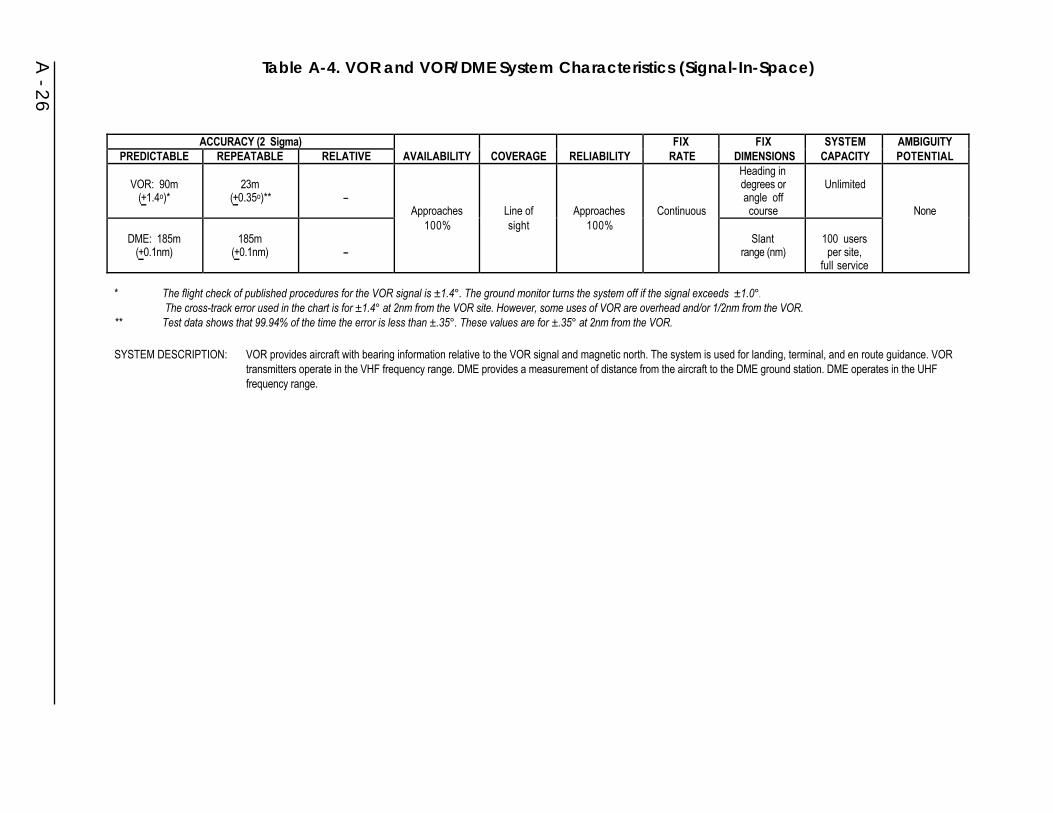
A - 26
ACCURACY (2 Sigma) FIX FIX SYSTEM AMBIGUITYPREDICTABLE REPEATABLE RELATIVE AVAILABILITY COVERAGE RELIABILITY RATE DIMENSIONS CAPACITY POTENTIAL
VOR: 90m(+1.4o)*
23m(+0.35o)** --
Approaches Line of Approaches Continuous
Heading indegrees orangle offcourse
Unlimited
None
DME: 185m(+0.1nm)
185m(+0.1nm) --
100% sight 100%Slant
range (nm)100 usersper site,
full service
*� The flight check of published procedures for the VOR signal is ±1.4°. The ground monitor turns the system off if the signal exceeds ±1.0°. � The cross-track error used in the chart is for ±1.4° at 2nm from the VOR site. However, some uses of VOR are overhead and/or 1/2nm from the VOR. ** � Test data shows that 99.94% of the time the error is less than ±.35°. These values are for ±.35° at 2nm from the VOR.
SYSTEM DESCRIPTION: VOR provides aircraft with bearing information relative to the VOR signal and magnetic north. The system is used for landing, terminal, and en route guidance. VORtransmitters operate in the VHF frequency range. DME provides a measurement of distance from the aircraft to the DME ground station. DME operates in the UHFfrequency range.
Table A-4. VOR and VOR/DME System Characteristics (Signal-In-Space)
• Relative - Although some course bending could influence position readingsbetween aircraft, the major relative error consists of the course selection,receiver and flight technical components. When combined using RSStechniques, the value is approximately ±4.3 degrees. The VOR groundstation relative error is ±0.35 degrees.
• Repeatable - The major error components of the ground system and receiverwill not vary appreciably in the short term. Therefore, the repeatable errorwill consist mainly of the flight technical error (the pilots’ ability to fly thesystem) which is ±2.3 degrees.
C. Availability
Because VOR coverage is overlapped by adjacent stations, the availability isconsidered to approach 100 percent for new solid state equipment.
D. Coverage
VOR has line-of-sight limitations which could limit ground coverage to 30 miles orless. At altitudes above 5,000 feet, the range is approximately 100 nm, and above20,000 feet, the range will approach 200 nm. These stations radiate approximately200 watts. Terminal VOR stations are rated at approximately 50 watts and are onlyintended for use within the terminal areas. Actual VOR coverage information iscontained in FAA Order 1010.55C.
E. Reliability
Due to advanced solid state construction and the use of remote maintenancemonitoring techniques, the reliability of solid state VOR approaches 100 percent.
F. Fix Rate
This system allows an essentially continuous update of deviation from a selectedcourse based on internal operations at a 30-update-per-second rate. Initialization isless than one minute after turn-on and will vary as to receiver design.
G. Fix Dimensions
The system shows magnetic bearing to a VOR station and deviation from a selectedcourse, in degrees.
H. System Capacity
The capacity of a VOR station is unlimited.
A - 27

I. Ambiguity
There is no ambiguity possible for a VOR station.
J. Integrity
VOR provides system integrity by removing a signal from use within ten seconds ofan out-of-tolerance condition detected by an independent monitor.
II. DME
A. Signal Characteristics
The signal characteristics of DME are summarized in Table A-4. The interrogator inthe aircraft generates a pulsed signal (interrogation) which, when of the correctfrequency and pulse spacings, is accepted by the transponder. In turn, thetransponder generates pulsed signals (replies) which are sent back and accepted bythe interrogator’s tracking circuitry. Distance is then computed by measuring thetotal round trip time of the interrogation and its reply. The operation of DME is thusaccomplished by paired pulse signals and the recognition of desired pulse spacingsaccomplished by the use of a decoder. The transponder must reply to allinterrogators. The interrogator must measure elapsed time between interrogation andreply pulse pairs and translate this to distance. All signals are vertically polarized.These systems are assigned in the 962 to 1,213 MHz frequency band with aseparation of 1 MHz.
The capability to use Y-channel service has been developed and implemented to avery limited extent (approximately 15 DMEs paired with localizers use the Y-channel frequencies). The term “Y-channel” refers to VOR frequency spacing.Normally, X-channel frequency spacing of 100 kHz is used. Y-channel frequenciesare offset from the X-channel frequencies by 50 kHz. In addition, Y-channel DMEsare identified by a wider interrogation pulse-pair time spacing of 0.036 msec versusX-channel DMEs at 0.012 msec spacing. X- and Y-channel applications arepresently limited to minimize user equipment changeovers.
B. Accuracy (2 sigma)
• Predictable - The ground station errors are less than ±0.1 nm. The overallsystem error (airborne and ground RSS) is not greater than ±0.5 nm or 3percent of the distance, whichever is greater.
• Relative - Although some errors could be introduced by reflections, the majorrelative error emanates from the receiver and flight technical error.
• Repeatable - Major error components of the ground system and receiver willnot vary appreciably in the short term.
A - 28

C. Availability
The availability of DME is considered to approach 100 percent, with positiveindication when the system is out-of-tolerance.
D. Coverage
DME has a line-of-sight limitation, which limits ground coverage to 30 nm or less.At altitudes above 5,000 feet, the range will approach 100 nm. En route stationsradiate at 1,000 watts. Terminal DMEs radiate 100 watts and are only intended foruse in terminal areas. Because of facility placement, almost all of the airways havecoverage and most of the CONUS has dual coverage, permitting DME/DME AreaNavigation (RNAV).
E. Reliability
With the use of solid state components and remote maintenance monitoringtechniques, the reliability of the DME approaches 100 percent.
F. Fix Rate
The system essentially gives a continuous update of distance to the facility. Actualupdate rate varies with the design of airborne equipment and system loading, withtypical rates of 10 per second.
G. Fix Dimensions
The system shows slant range to the DME station in nm.
H. System Capacity
For present traffic capacity 110 interrogators are considered reasonable. Futuretraffic capacity could be increased when necessary through reduced individualaircraft interrogation rates and removal of beacon capacity reply restrictions.
I. Ambiguity
There is no ambiguity in the DME system.
J. Integrity
DME provides system integrity by removing a signal from use within ten seconds ofan out-of-tolerance condition detected by an independent monitor.
A - 29

III.TACAN
A. Signal Characteristics
TACAN is a short-range UHF (962 to 1,213 MHz) radionavigation system designedprimarily for aircraft use. TACAN transmitters and responders provide the datanecessary to determine magnetic bearing and distance from an aircraft to a selectedstation. TACAN stations in the U.S. are frequently collocated with VOR stations.These facilities are known as VORTACs. The signal characteristics of TACAN aresummarized in Table A-5.
B. Accuracy (2 sigma)
• Predictable - The ground station errors are less than ±1.0 degree for azimuthfor the 135 Hz element and ±4.5 degrees for the 15 Hz element. Distanceerrors are the same as DME errors.
• Relative - The major relative errors emanate from course selection, receiverand flight technical error.
• Repeatable - Major error components of the ground station and receiver willnot vary greatly in the short term. The repeatable error will consist mainly ofthe flight technical error.
C. Availability
A TACAN station can be expected to be available 98.7 percent of the time.
D. Coverage
TACAN has a line-of-sight limitation which limits ground coverage to 30 nm orless. At altitudes of 5,000 feet, the range will approach 100 nm; above 18,000 feet,the range approaches 200 nm. This coverage is based on a 5 kW station.
E. Reliability
A TACAN station can be expected to be reliable 99 percent of the time. Unreliablestations, as determined by remote monitors, are automatically removed from service.
F. Fix Rate
TACAN provides a continuous update of the deviation from a selected course.Initialization is less than one minute after turn on. Actual update rate varies with thedesign of airborne equipment and system loading.
A - 30

A - 31
ACCURACY (2 Sigma) FIX FIX SYSTEM AMBIGUITYPREDICTABLE REPEATABLE RELATIVE AVAILABILITY COVERAGE RELIABILITY RATE DIMENSIONS CAPACITY POTENTIAL
Azimuth +1o
(+ 63m at3.75km)
Azimuth +1o
(+ 63m at 3.75km)Azimuth +1o
(+63m at 3.75km) 98.7% Line of 99% Continuous Distance
110 fordistance.
No ambiguityin range.
Sight potential
DME: 185m(+0.1nm)
DME: 185m(+0.1nm)
DME: 185m(+0.1nm)
sight and bearingfrom station
Unlimitedin azimuth
for ambiguityat multiples
of 40o
SYSTEM DESCRIPTION: TACAN is a short-range UHF navigation system used by the military. The system provides range, bearing and station identification. When TACAN is collocatedwith a VOR it is called a VORTAC facility.
Table A-5. TACAN System Characteristics (Signal-In-Space)
G. Fix Dimensions
The system shows magnetic bearing, deviation in degrees, and distance to theTACAN station in nautical miles.
H. System Capacity
For distance information, 110 interrogators are considered reasonable for presenttraffic handling. Future traffic handling could be increased when necessary throughreduced airborne interrogation rates and increased reply rates. Capacity for theazimuth function is unlimited.
I. Ambiguity
There is no ambiguity in the TACAN range information. There is a slight probabilityof azimuth ambiguity at multiples of 40 degrees.
J. Integrity
TACAN provides system integrity by removing a signal from use within ten secondsof an out-of-tolerance condition detected by an independent monitor.
A.2.6 ILS
ILS is a precision approach system normally consisting of a localizer facility, a glideslope facility, and associated VHF marker beacons. It provides vertical andhorizontal navigational (guidance) information during the approach to landing at anairport runway.
At present, ILS is one of the primary worldwide, ICAO-approved, precision landingsystem. This system is presently adequate, but has limitations in siting, frequencyallocation, cost, and performance. The characteristics of ILS are summarized inTable A-6.
A. Signal Characteristics
The localizer facility and antenna are typically located 1,000 feet beyond the stopend of the runway and provides a VHF (108 to 112 MHz) signal. The glide slopefacility is located approximately 1,000 feet from the approach end of the runway andprovides a UHF (328.6 to 335.4 MHz) signal. Marker beacons are located along anextension of the runway centerline and identify particular locations on the approach.Ordinarily, two 75 MHz beacons are included as part of the instrument landingsystem: an outer marker at the final approach fix (typically four to seven miles fromthe approach end of the runway) and a middle marker located 3,500 feet plus orminus 250 feet from the runway threshold. The middle marker is located so as tonote impending visual acquisition of the runway in conditions of minimum visibilityfor Category I ILS approaches. An inner marker, located approximately 1,000 feetfrom the threshold, is normally associated with Category II and III ILS approaches.
A - 32

A - 33
ACCURACY AT DECISION HEIGHT(Meters - 2 Sigma) FIX FIX SYSTEM AMBIGUITY
CATEGORY AZIMUTH ELEVATION AVAILABILITY COVERAGE RELIABILITY RATE** DIMENSION CAPACITY POTENTIAL
1 +9.1 +3.0 Normal limitsfrom center
98.6% withpositive Limited
2 +4.6 +1.4 Approaches99%
of localizer+10o out
to 18nm and
indicationwhen thesystem is
ContinuousHeading and
deviationin degrees
only byaircraft
separationNone
3 +4.1 +0.4+35o outto 10nm
out oftolerance
requirements
*� Signal availability in the coverage volume.
SYSTEM DESCRIPTION: The Instrument Landing System (ILS) is a precision approach system consisting of a localizer facility, a glide scope facility and two or three VHF marker beacons.The VHF (108-112MHz) localizer facility provides accurate, single path horizontal guidance information. The UHF (328.6-335.4MHz) glide scope provides precise,single path, vertical guidance information to a landing aircraft.
Table A-6. ILS Characteristics (Signal-In-Space)

B. Accuracy
For typical air carrier operations at a 10,000 foot runway, the course alignment(localizer) at threshold is maintained within ±25 feet. Course bends during the finalsegment of the approach do not exceed ±0.06 degrees (2 sigma). Glide slope coursealignment is maintained within ±7.0 feet at 100 feet (2 sigma) elevation and glidepath bends during the final segment of the approach do not exceed ±0.07 degrees (2sigma).
C. Availability
To further improve the availability of service from ILS installations, vacuum tubeequipment has been replaced with solid state equipment. Service availability is nowapproaching 99 percent.
D. Coverage
Coverage for individual systems is as follows:
Localizer: ±2ocentered about runway centerline.
Glide Slope: Nominally 3oabove the horizontal.
Marker Beacons: ±40o (approximately) on minor axis (along approach path) ±85o
(approximately) on major axis.
E. Reliability
ILS reliability is 98.6 percent. However, terrain and other factors may imposelimitations upon the use of the ILS signal. Special account must be taken of terrainfactors and dynamic factors such as taxiing aircraft which can cause multipath.
In some cases, to resolve ILS siting problems, use has been made of localizers withaperture antenna arrays and two frequency systems. In the case of the glide slope,use has been made of wide aperture, capture effect image arrays and single-frequency infrared arrays to provide service at difficult sites.
F. Fix Rate
The glide slope and localizer provide continuous fix information, although the userwill receive position updates at a rate determined by receiver/display design(typically more than 5 updates per second). Marker beacons which provide anaudible and visual indication to the pilot are sited at specific points along theapproach path as indicated in Table A-7.
A - 34

Table A-7. Aircraft Marker Beacons
G. Fix Dimensions
ILS provides both vertical and horizontal guidance with glide slope and localizersignals. At periodic intervals (passing over marker beacons) distance to threshold isobtained.
H. System Capacity
ILS has no capacity limitations except those imposed by aircraft separationrequirements since aircraft must be in trail to use the system.
I. Ambiguity
Any potential ambiguities are resolved by imposing system limitations as describedin Section A.2.6.E.
J. Integrity
ILS provides system integrity by removing a signal from use when an out-of-tolerance condition is detected by an integral monitor. The shutdown delay for eachcategory is given below:
Shutdown Delay
Localizer Glide Slope
CAT I <10 sec <6 secCAT II <5 sec <2 secCAT III <2 sec <2 sec
A.2.7 MLS
MLS provides a common civil/military landing system to meet the full range of useroperational requirements, as defined in the ICAO list of 38 operational requirementsfor precision approach and landing systems, to the year 2000 and beyond. It wasoriginally intended to be a replacement for ILS, used by both civil and militaryaircraft, and the Ground Controlled Approach (GCA) system used primarily by
A - 35
MARKERDESIGNATION
TYPICAL DISTANCE TOTHRESHOLD
AUDIBLESIGNAL
LIGHTCOLOR
Outer 4-7nmContinuous dashes
(2/sec) Blue
Middle 3,250-3,750 ftContinuous alternating
dot-dash Amber
Inner 1,000 ftContinuous dots
(6/sec) White

military operators. However, augmented GPS systems are now envisioned to satisfythe majority of requirements originally earmarked for MLS. Accordingly, the FAAhas terminated all R&D activity associated with MLS. The system characteristics ofMLS are summarized in Table A-8.
A. Signal Characteristics
MLS transmits signals that enable airborne units to determine the precise azimuthangle, elevation angle, and range. The technique chosen for the angle function of theMLS is based upon Time-Referenced Scanning Beams (TRSB). All angle functionsof MLS operate in the 5.00 to 5.25 GHz band. Ranging is provided by DMEoperating in the 962 to 1,213 MHz band. An option is included in the signal formatto permit a special purpose system to operate in the 15.4 to 15.7 GHz band.
B. Accuracy (2 sigma)
The azimuth accuracy is ±13.0 feet (+4.0m) at the runway threshold approachreference datum and the elevation accuracy is ±2.0 feet (+0.6m). The lower surfaceof the MLS beam crosses the threshold at 8 feet (2.4 meters) above the runwaycenterline. The flare guidance accuracy is ±1.2 feet throughout the touchdown zoneand the DME accuracy is ±100 feet for the precision mode and ±1,600 feet for thenonprecision mode.
C. Availability
Equipment redundancy, as well as remote maintenance monitoring techniques,should allow the availability of this system to approach 100 percent.
D. Coverage
Current plans call for the installation of systems with azimuthal coverage of ±40ooneither side of the runway centerline, elevation coverage from 0o to a minimum of15oover the azimuthal coverage area, and out to 20 nm. A few systems will have±60oazimuthal coverage. MLS signal format has the capability of providingcoverage to the entire 360o area but with less accuracy in the area outside theprimary coverage area of +60o of runway centerline. There will be simultaneousoperations of ILS and MLS during the transition period.
E. Reliability
The MLS signals are generally less sensitive than ILS signals to the effects of snow,vegetation, terrain, structures, and taxiing aircraft. This allows the reliability of thissystem to approach 100 percent.
A - 36

A - 37
ACCURACY AT DECISION HEIGHT(Meters - 2 Sigma) FIX FIX SYSTEM AMBIGUITY
CATEGORY AZIMUTH ELEVATION AVAILABILITY COVERAGE RELIABILITY RATE** DIMENSION CAPACITY POTENTIAL
1 +9.1 +3.0+40o from
2 +4.6 +1.4Expected
to approach100%
center line ofrunway out
to 20nm in both
Expectedto approach
100%
6.5-39fixes/sec
depending
Heading anddeviation
in degrees.
Limited onlyby aircraftseparation
None
3 +4.1 +0.4directions* on function Range in nm requirements
* � There are provisions for 360° out to 20nm.
SYSTEM DESCRIPTION: The Microwave Landing System (MLS) is a precision landing system that will operate in the 5-5.25 GHz band. Ranging is provided by precision DME operating in 962-1,213 MHz band.
Table A-8. MLS Characteristics (Signal-In-Space)
F. Fix Rate
Elevation angle is transmitted at 39 samples per second, azimuth angle at 13 samplesper second, and back azimuth angle at 6.5 samples per second. Usually, the airbornereceiver averages several data samples to provide fixes of 3 to 6 samples per second.A high rate azimuth angle function of 39 samples per second is available and isnormally used where there is no need for flare elevation data.
G. Fix Dimensions
This system provides signals in all three dimensions and can provide time if aircraftare suitably equipped.
H. System Capacity
DME signals of this system are capacity limited; the system limits are approachedwhen 110 aircraft are handled.
I. Ambiguity
No ambiguity is possible for the azimuth or elevation signals. Only a very smallprobability for ambiguity exists for the range signals and then only for multipathcaused by moving reflectors.
J. Integrity
MLS integrity is provided by an integral monitor. The monitor shuts down the MLSwithin one second of an out-of-tolerance condition.
A.2.8 Aeronautical Radiobeacons
Radiobeacons are nondirectional radio transmitting stations which operate in thelow- and medium-frequency bands to provide ground wave signals to a receiver. Anautomatic direction finder (ADF) is used to measure the bearing of the transmitterwith respect to an aircraft or vessel.
The characteristics of aeronautical NDBs are summarized in Table A-9.
A. Signal Characteristics
Aeronautical NDBs operate in the 190 to 415 kHz and 510 to 535 kHz bands. (Note:NDBs is the 285-325 kHz band are secondary to maritime radiobeacons.) Theirtransmissions include a coded continuous-wave (CCW) or modulated continuous-wave (MCW) signal to identify the station. The CCW signal is generated bymodulating a single carrier with either a 400 Hz or a 1,020 Hz tone for Morse codeidentification. The MCW signal is generated by spacing two carriers either 400 Hzor 1,020 Hz apart and keying the upper carrier to give the Morse code identification.
A - 38
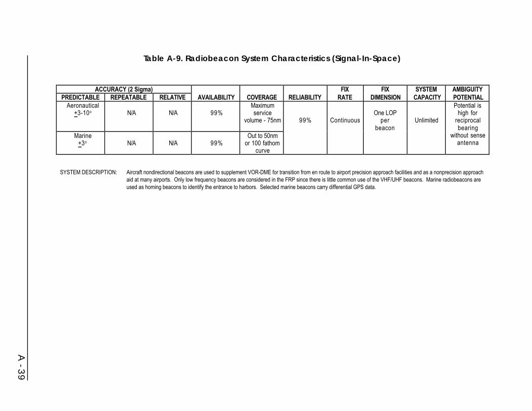
A - 39
ACCURACY (2 Sigma) FIX FIX SYSTEM AMBIGUITYPREDICTABLE REPEATABLE RELATIVE AVAILABILITY COVERAGE RELIABILITY RATE DIMENSION CAPACITY POTENTIAL
Aeronautical+3-10o N/A N/A 99%
Maximumservice
volume - 75nm 99% ContinuousOne LOP
per Unlimited
Potential ishigh for
reciprocal
Marine+3o N/A N/A 99%
Out to 50nmor 100 fathom
curve
beacon bearingwithout sense
antenna
SYSTEM DESCRIPTION: Aircraft nondirectional beacons are used to supplement VOR-DME for transition from en route to airport precision approach facilities and as a nonprecision approachaid at many airports. Only low frequency beacons are considered in the FRP since there is little common use of the VHF/UHF beacons. Marine radiobeacons areused as homing beacons to identify the entrance to harbors. Selected marine beacons carry differential GPS data.
Table A-9. Radiobeacon System Characteristics (Signal-In-Space)

B. Accuracy
Positional accuracy derived from the bearing information is a function of geometryof the LOPs, the accuracy of compass heading, measurement accuracy, distancefrom the transmitter, stability of the signal, time of day, nature of the terrain betweenbeacon and craft, and noise. In practice, bearing accuracy is on the order of ±3 to±10 degrees. Achievement of ±3 degree accuracy requires that the RDF be calibratedbefore it is used for navigation by comparing radio bearings to accurate bearingsobtained visually on the transmitting antenna. Since most direction finder receiverswill tune to a number of radio frequency bands, transmissions from sources ofknown location, such as AM broadcast stations, are also used to obtain bearings,generally with less accuracy than obtained from radiobeacon stations. For FAA flightinspection, NDB system accuracy is stated in terms of permissible needle swing: ±5degrees on approaches and ±10 degrees in the en route area.
C. Availability
Availability of aeronautical NDBs is in excess of 99 percent.
D. Coverage
Extensive NDB coverage is provided by 1,575 ground stations, of which the FAAoperates 728.
E. Reliability
Reliability is in excess of 99 percent.
F. Fix Rate
The beacon provides continuous bearing information.
G. Fix Dimensions
In general, one LOP is available from a single radiobeacon. If within one range oftwo or more beacons, a two-dimensional fix may be obtained.
H. System Capacity
An unlimited number of receivers may be used simultaneously.
I. Ambiguity
The only ambiguity which exists in the radiobeacon system is one of reciprocalbearing provided by some receiving equipment which does not employ a senseantenna to resolve direction.
A - 40

J. Integrity
A radiobeacon is an omnidirectional navigational aid. For aviation radiobeacons,out-of-tolerance conditions are limited to output power reduction below operatingminimums and loss of the transmitted station identifying tone. The radiobeaconsused for nonprecision approaches are monitored and will shut down within 15seconds of an out-of-tolerance condition.
A.2.9 Maritime Radiobeacons
Radiobeacons are nondirectional radio transmitting stations which operate in thelow- and medium-frequency bands to provide ground wave signals to a receiver. AnRDF is used to measure the bearing of the transmitter with respect to an aircraft orvessel.
There are 4 USCG-operated marine radiobeacons. These marine radiobeacons areexpected to be phased out by the year 2000.
A. Signal Characteristics
Marine radiobeacons operate in the 285 to 325 kHz band. The signal characteristicsfor marine radiobeacons are summarized in Table A-9. Due to single carrieroperations which eliminate the Morse tone identifier, USCG DGPS beacons do notconform to the traditional radiobeacon standards.
B. Accuracy
Positional accuracy derived from the bearing information is a function of geometryof the LOPs, the accuracy of compass heading, measurement accuracy, distancefrom the transmitter, stability of the signal, time of day, nature of the terrain betweenbeacon and craft, and noise. In practice, bearing accuracy is on the order of ±3 to±10 degrees. Achievement of ±3 degree accuracy requires that the RDF be calibratedbefore it is used for navigation by comparing radio bearings to accurate bearingsobtained visually on the transmitting antenna. Since most direction finder receiverswill tune to a number of radio frequency bands, transmissions from sources ofknown location, such as AM broadcast stations, are also used to obtain bearings,generally with less accuracy than obtained from radiobeacon stations.
C. Availability
Availability of marine radiobeacons is in excess of 99 percent.
D. Coverage
The coverage from marine radiobeacons has been steadily declining over the lastfour to six years. There is some evidence that privately maintained and operatedbeacons are still being used in the Gulf Coast region of the U.S. (e.g., homingbeacons for oil rigs).
A - 41

E. Reliability
Reliability is in excess of 99 percent. Radiobeacons used for DGPS broadcasts willhave reliability in excess of 99.7 percent.
F. Fix Rate
The beacon signal is provided continuously.
G. Fix Dimensions
In general, one LOP is available from a single radiobeacon.
H. System Capacity
An unlimited number of receivers may be used simultaneously.
I. Ambiguity
The only ambiguity which exists in the radiobeacon system is one of reciprocalbearing provided by some receiving equipment which does not employ a senseantenna to resolve direction.
J. Integrity
A radiobeacon is an omnidirectional navigational aid. Notification of outages isprovided by a broadcast Notice to Mariners. Outages of long duration will also bepublished in the Local Notice to Mariners.
A.3 Navigation Information Services
A.3.1 USCG Navigation Information Service
The U.S. Coast Guard’s Navigation Information Service (NIS), formerly the GPSInformation Center, is the operational entity of the Civil GPS Service (CGS) whichprovides GPS status information to civil users of GPS. Its input is based on datafrom the GPS Control Segment, Department of Defense, and other sources. Themission of the NIS is to gather, process and disseminate timely GPS, Loran-C,Omega, and DGPS radionavigation information as well as general maritimenavigation information. Specifically, the functions performed by the NIS include thefollowing:
• Act as the single focal point for civil users to report problems with GPS.
• Provide Operational Advisory Broadcast (OAB) Service.
• Answer questions by telephone, written correspondence, or electronic mail.
A - 42
• Provide information to the public on the NIS services available.
• Provide instruction on the access and use of the information servicesavailable.
• Maintain tutorial, instructional, and other relevant handbooks and materialfor distribution to users.
• Maintain records of GPS broadcast information, GPS databases or relevantdata for reference purposes.
• Maintain bibliography of GPS publications.
• Maintain and augment the computer and communications equipment asrequired.
• Develop new user services as required.
Information on GPS and USCG-operated radionavigation systems can be obtainedfrom the USCG’s Navigation Center (NAVCEN), 7327 Telegraph Road, Alexandria,VA 22315-3998. Table A-10 and Figure A-5 show the services through which theNIS provides Operational Advisory Broadcasts. NAVCEN’s 24-hour hotline: (703)313-5900. NAVCEN’s E-mail address: [email protected]. InternetWWW address: http://www.navcen.uscg.mil/.
A.3.2. GPS NOTAM/Aeronautical Information System
The Air Force Flight Standards Agency has established a fundamental GPS Notice toAirmen (NOTAM) requirement for flight planning purposes. This requirement hasbeen coordinated with the FAA and the other Services to be consistent withestablished flying procedures and safety standards for all DOD requirements.
On October 28, 1993, DOD began providing notice of GPS satellite vehicle outagesthrough the NOTAM system. These NOTAMs are reformatted Notice Advisories toNAVSTAR Users (NANUs) provided by the 2nd Space Operations Squadron(2SOPS) at the GPS Master Control Station (MCS). The outages are disseminated tothe NOTAM Office at least 48 hours before they are scheduled to occur. Unexpectedoutages also are reported by the 2SOPS to the U.S. NOTAM Office (USNOF).
Example: !GPS 07/010 GPS PRN 14 OTS EFF 07160300-07161500
This NOTAM shows PRN 14 scheduled out of service on July 16 from 0300 until1500 UTC. Satellite NOTAMs are issued as both a domestic NOTAM under theKGPS identifier and as an international NOTAMs under the KNMH identifier. Thismakes the information accessible to both civilian and military aviators.Unfortunately, this information is meaningless to the pilot unless there is a methodto interpret its effects on availability for the intended operation.
A - 43
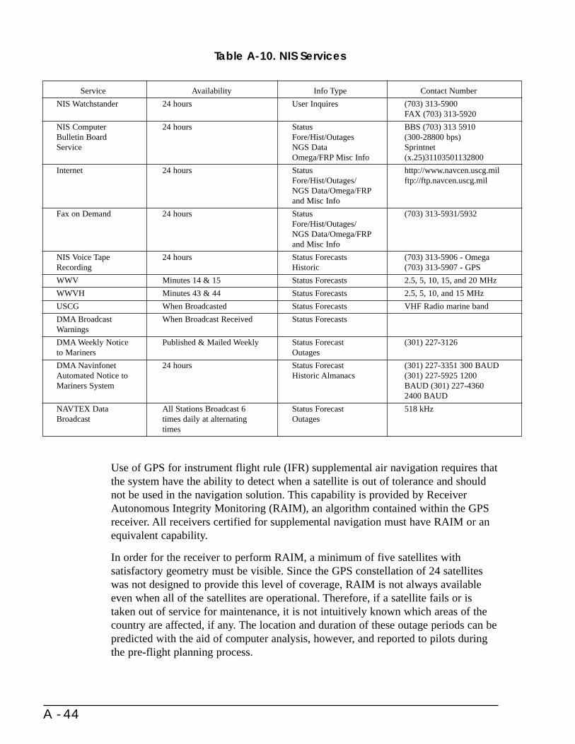
Use of GPS for instrument flight rule (IFR) supplemental air navigation requires thatthe system have the ability to detect when a satellite is out of tolerance and shouldnot be used in the navigation solution. This capability is provided by ReceiverAutonomous Integrity Monitoring (RAIM), an algorithm contained within the GPSreceiver. All receivers certified for supplemental navigation must have RAIM or anequivalent capability.
In order for the receiver to perform RAIM, a minimum of five satellites withsatisfactory geometry must be visible. Since the GPS constellation of 24 satelliteswas not designed to provide this level of coverage, RAIM is not always availableeven when all of the satellites are operational. Therefore, if a satellite fails or istaken out of service for maintenance, it is not intuitively known which areas of thecountry are affected, if any. The location and duration of these outage periods can bepredicted with the aid of computer analysis, however, and reported to pilots duringthe pre-flight planning process.
A - 44
Service Availability Info Type Contact Number
NIS Watchstander 24 hours User Inquires (703) 313-5900FAX (703) 313-5920
NIS Computer 24 hours Status BBS (703) 313 5910Bulletin Board Fore/Hist/Outages (300-28800 bps)Service NGS Data Sprintnet
Omega/FRP Misc Info (x.25)31103501132800
Internet 24 hours Status http://www.navcen.uscg.milFore/Hist/Outages/ ftp://ftp.navcen.uscg.milNGS Data/Omega/FRPand Misc Info
Fax on Demand 24 hours Status (703) 313-5931/5932Fore/Hist/Outages/NGS Data/Omega/FRPand Misc Info
NIS Voice Tape 24 hours Status Forecasts (703) 313-5906 - OmegaRecording Historic (703) 313-5907 - GPS
WWV Minutes 14 & 15 Status Forecasts 2.5, 5, 10, 15, and 20 MHz
WWVH Minutes 43 & 44 Status Forecasts 2.5, 5, 10, and 15 MHz
USCG When Broadcasted Status Forecasts VHF Radio marine band
DMA Broadcast When Broadcast Received Status ForecastsWarnings
DMA Weekly Notice Published & Mailed Weekly Status Forecast (301) 227-3126to Mariners Outages
DMA Navinfonet 24 hours Status Forecast (301) 227-3351 300 BAUDAutomated Notice to Historic Almanacs (301) 227-5925 1200Mariners System BAUD (301) 227-4360
2400 BAUD
NAVTEX Data All Stations Broadcast 6 Status Forecast 518 kHzBroadcast times daily at alternating Outages
times
Table A-10. NIS Services

Notification of site specific outages provides the pilot with information regardingGPS RAIM availability for nonprecision approach at the filed destination.
Site specific GPS NOTAMs are computed based on criteria in the RTCA/DO-208,"Minimum Operational Performance Standards for Airborne SupplementalNavigation Equipment Using Global Positioning System (GPS)," dated July 1991,and FAA Technical Standard Order (TSO)-C129(a), "Airborne SupplementalNavigation Equipment Using the Global Positioning System (GPS)." The baselineRAIM algorithm, as specified in the MOPS and TSO, is used for computing theNOTAMs for GPS.
GPS almanac data is received via an antenna on the roof of the FAA or sent bymodem from the GPS Master Control Station to a computer at the U.S. NOTAMOffice. The almanac and satellite health status data are input into the RAIMalgorithm and processed against a database of airfields to determine location specificoutages. The outage information is then distributed in the form of a NOTAM to U.S.military aviators and as aeronautical information to U.S. Flight Service Stations forcivilian aviators. This occurs daily for an advance 48 hour period or whenever achange occurs in a satellite’s health status.
The military GPS NOTAM system was officially declared operational on May 16,1995. An example military NOTAM output from the system sent through NATCOMto the Aviation Weather Network (AWN) to the CONUS Meteorological Distribution
A - 45
NavigationInformation
Service
SystemHealth
ScheduledOutages
UserDocuments
Mariners
Pilots
DOD
Surveyors
Land Nav
Fleet Manager
Space
Nav
Time
Transfer
Universities
RNAVStatus
Information
UserCommunity
InformationSources
GPSSegment
OMEGASegment
LORAN-CSegment
DGPSSegment
Local Noticeto Mariners
MarineCommunications
RecreationalBoatingSafety
OtherInformation
sources
InfoPack
ComputerBBS
VoiceRecording
Telephone
WWVWWVH
USCG/DMABroadcasts
NAV InfoNetwork
NavtexBroadcast
Internet
DistributionMedia
Fax on
Demand
Figure A-5. NIS Information Flow
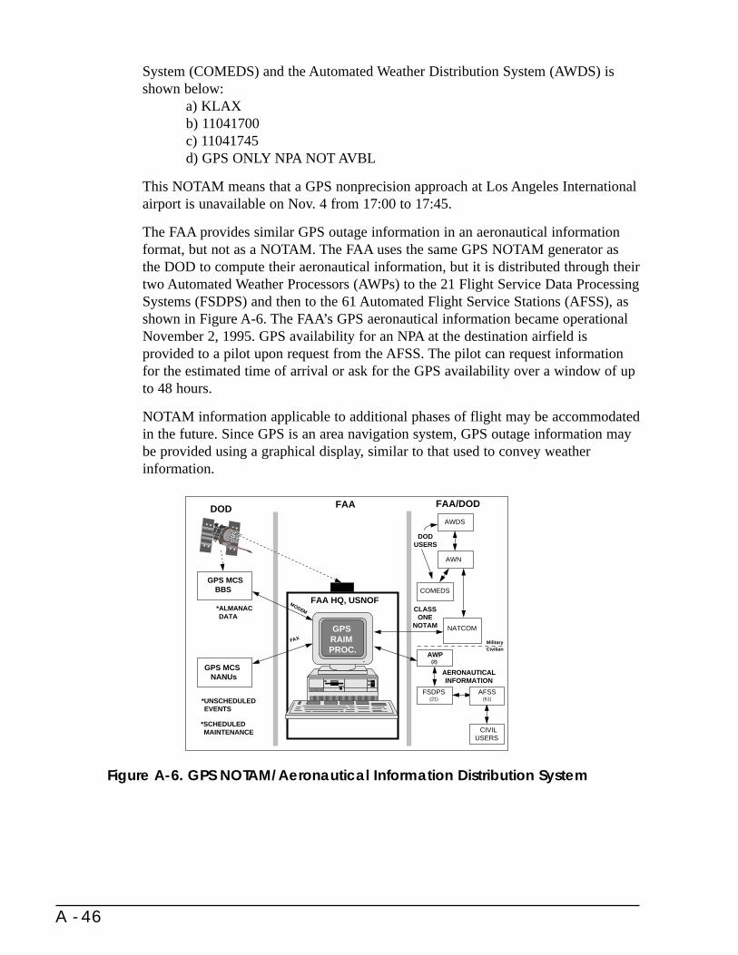
System (COMEDS) and the Automated Weather Distribution System (AWDS) isshown below:
a) KLAXb) 11041700c) 11041745d) GPS ONLY NPA NOT AVBL
This NOTAM means that a GPS nonprecision approach at Los Angeles Internationalairport is unavailable on Nov. 4 from 17:00 to 17:45.
The FAA provides similar GPS outage information in an aeronautical informationformat, but not as a NOTAM. The FAA uses the same GPS NOTAM generator asthe DOD to compute their aeronautical information, but it is distributed through theirtwo Automated Weather Processors (AWPs) to the 21 Flight Service Data ProcessingSystems (FSDPS) and then to the 61 Automated Flight Service Stations (AFSS), asshown in Figure A-6. The FAA’s GPS aeronautical information became operationalNovember 2, 1995. GPS availability for an NPA at the destination airfield isprovided to a pilot upon request from the AFSS. The pilot can request informationfor the estimated time of arrival or ask for the GPS availability over a window of upto 48 hours.
NOTAM information applicable to additional phases of flight may be accommodatedin the future. Since GPS is an area navigation system, GPS outage information maybe provided using a graphical display, similar to that used to convey weatherinformation.
Figure A-6. GPS NOTAM/Aeronautical Information Distribution System
A - 46
FAA
GPS
RAIMPROC.
FAA HQ, USNOF
FAA/DOD
DODUSERS
AWDS
AWN
COMEDS
NATCOM
CLASS ONE
NOTAM
CIVIL USERS
AERONAUTICALINFORMATION
AWP(2)
AFSS(61)
FSDPS(21)
FAX
MODEM
GPS MCS NANUs
DOD
GPS MCS BBS
*ALMANAC**DATA
*UNSCHEDULED EVENTS
*SCHEDULED MAINTENANCE
MilitaryCivilian
Appendix BReference Systems
B.1 Map and Chart Reference Systems
Geodetic datums are reference systems used as a basis for providing horizontal andvertical positions of features on the surface of the Earth. They can be established atall levels of government (international, national, and local) and form the legal basisfor positioning and navigation. Historically, horizontal and vertical datums havebeen determined independent of one another. Older horizontal datums have usuallybeen local or regional in nature and non-geocentric. Vertical positions (orthometricheights) have been referenced to an equipotential surface that approximated meansea level.
With the advent of satellite positioning systems, especially GPS, it is possible todetermine three dimensional coordinates related to a common geocentric referencesystem. Rather than orthometric heights, GPS provides geocentric radius vectors,expressed as ellipsoid heights above a geocentric reference ellipsoid with a specifiedsemi-major axis and flattening. Orthometric heights and ellipsoid heights can differby more than 100 meters and must not be confused. They can be related to oneanother using the gravimetrically determined separations between the ellipsoid towhich ellipsoid heights are referred and the equipotential surface to whichorthometric heights are referred. This separation is known as geoid height. Geoidheight models (e.g., GEOID93, GEOID96, EGM96) have been developed to supportconversions between orthometric and ellipsoid heights.
Within the U.S. the National Geodetic Survey (NGS) is the primary civil Federalagency responsible for establishment of datums. Until recently the horizontal datumused throughout most of the U.S. and Canada was the North American Datum of1927 (NAD 27). NAD 27 is not Earth centered. In 1986 NGS completed a newhorizontal datum known as the North American Datum of 1983 (NAD 83). NAD 83
B - 1
is nominally geocentric. NAD 83 is now the legal horizontal datum for surveying,mapping and charting in the U.S. Until recently, the orthometric height datum for theU.S. was the National Geodetic Vertical Datum of 1929 (NGVD29). In 1991 theNGS completed a new vertical datum, the North American Vertical Datum of 1988(NAVD 88). NAVD 88 is now the legal vertical datum for orthometric heights in theU.S.
With the advent of space technology, geodesy and navigation are increasingly beingreferenced to three dimensional, Earth centered reference systems. Three suchsystems are in common use at present. They are: NAD 83 (extended to be threedimensional), World Geodetic System of 1984 (WGS 84), and the InternationalTerrestrial Reference Frame (ITRF) developed by the International Earth RotationService (IERS). New ITRF systems are produced every 1 to 2 years as moreaccurate information becomes available. Changes in station coordinates betweenITRF systems are currently at the few centimeter level. WGS 84 was developed bythe U.S. Department of Defense (DOD). The realization of WGS 84 has improvedwith time so that it is closely aligned with ITRF. Currently, WGS 84 and the mostrecent ITRF systems are in agreement to better than a decimeter. NAD 83 wasextended to be three dimensional using space system stations included in the originalNAD 83 adjustment supplemented by the introduction of a nationwide network ofGPS stations. All versions of the three reference systems differ from one another byno more than about two meters. Therefore, for many mapping, charting andnavigation purposes they can be considered equivalent.
By interagency agreements between NOAA and the USCG and FAA, NGS isproviding NAD 83 positions for stations of the USCG DGPS stations which supportmarine navigation and the FAA WAAS stations which support air navigation.
B.2 Nautical Charts
Most nautical charts are based on regional horizontal datums which have beendefined over the years independent of each other.
These include charts published by the National Imagery and Mapping Agency(NIMA) and NOS. In addition, in many parts of the world, the positional accuracyof chart features (such as hazards to navigation) sometimes varies from chart tochart and, in some cases, within a chart. Certain charts for waters in the southernhemisphere, for example, do not show islands in their correct geodetic positions,absolute or relative. Therefore, datums and limited chart accuracy must beconsidered when a navigational fix is plotted by a navigator on a nautical chart.Modern navigational positioning is based on satellite systems which are geocentricby definition, and these satellite coordinate systems differ significantly in manycases with the local or regional datums currently used for nautical charts. In additionto this difference, the plotted detail, such as soundings and navigational aids, containa minimal plottable error that ranges between 0.5 mm and 1.0 mm on paper.
B - 2

Virtually all radionavigation equipment incorporating coordinate converters(automatic computation of geodetic latitude and longitude from data received from aradionavigation system) were, until recently, programmed with the World GeodeticSystem of 1972 (WGS 72). Today, new radionavigation equipment coordinates,especially from differential GPS systems, are computed based on WGS 84, or,equivalently, in the U.S., NAD 83.
The large majority of the nautical charts published by NOS have been compiledbased on a regional datum: NAD 27. The remaining NOS nautical charts werepublished on eight other local or regional datums. As stated, NOS has now adopted ageocentric datum: NAD 83. NOS has completed the conversion of most of itsnautical charts to NAD 83. The charts of the Pacific islands, published by NOS, willbe compiled based on WGS 84. As stated before, for charting purposes, NAD 83 isequivalent to WGS 84. As charts are converted to NAD 83, datum transformationnotes will be added which report the amount of shifts from NAD 27 coordinates foreach chart. These shifts can be in excess of 100 m and care must be taken not to mixNAD 83 and NAD 27 values while navigating.
Improvements in worldwide navigation accuracy, which are occurring with theimplementation of GPS, will be significant. However, the ability to navigate safelyalong the coastlines of the world and on the high seas will remain limited whereaccurate, up-to-date hydrography and associated topographic features are not allpositioned on the same satellite-based reference system.
B.3 Aeronautical Charts
The ultimate responsibility for the accuracy of air cartographic positional data restswith NOAA. 49 U.S.C Section 4472 authorizes the FAA, subject to availableappropriations, to arrange for the publication of aeronautical maps and chartsnecessary for the safe and efficient movement of aircraft in air navigation utilizingthe facilities and assistance of other Federal agencies. Through agreement betweenthe FAA and NOAA the National Ocean Service (NOS) of NOAA provides many ofthe services necessary to provide the required maps and charts. Within the NationalAirspace System (NAS), the NGS, a component of NOS, establishes the basic U.S.datums that are the basis for aeronautical charting. NGS conducts the AirportObstruction Chart Surveys (AOC Surveys) which provide the basis for positioningof navigation aids, obstructions, etc. needed to produce obstruction charts at about930 major U.S. civil airports. The results of these extensive ground based and aerialphotographic surveys are delivered to users in both digital and paper chart format.
NGS also conducts two other types of surveys in support of the FAA: AreaNavigation Approach (ANA) surveys and Engine Out Departure (EOD) surveys.ANA surveys provide runway or vertical landing point positions, obstructionlocation, GPS antenna siting, and other positioning information for use indeveloping precision and nonprecision instrument approach procedures for aircraftusing navigation systems such as GPS. In addition these surveys provide positionsand elevations for selected navigational aids associated with the airport or heliport.
B - 3

Surveys are expected to encompass on the order of 4,000 airports and perhaps asmany as 2,000 heliports by the year 2000 to support conversion to GPS navigation.EOD surveys will also be performed to provide runway and obstruction informationfor use in determining the maximum allowable takeoff weights for civil aircraftassuming a complete failure of one engine at V1.
B.4 Electronic Chart Display Information System (ECDIS)
The Electronic Chart Display Information System (ECDIS) has emerged as apromising navigation aid that will result in significant improvements to maritimesafety and commerce. More than simply a graphics display, ECDIS is a real-timegeographic information system (GIS) that combines both spatial and textual datainto a readily useful operational tool. As an automated decision aid that is capable ofcontinuously determining a vessel’s position in relation to land, charted objects, aidsto navigation, and unseen hazards, ECDIS represents an entirely new approach tomaritime navigation and piloting. It is expected that ECDIS will eventually replacethe need to carry paper charts.
The development of an international performance standard for ECDIS was finalizedby the International Maritime Organization (IMO) in May 1994. The IMOPerformance Standards for ECDIS were formally adopted by the NineteenthAssembly of IMO on November 23, 1995. To ensure early dissemination, IMOissued ECDIS Performance Standards as MCS/Circ. 637 on May 27, 1994.
As specified in the IMO Performance Standards, the primary function of ECDIS isto contribute to safe navigation. ECDIS must be capable of displaying all chartinformation necessary for safe and efficient navigation organized by, and distributedon the authority of, government-authorized hydrographic offices. With adequatebackup arrangements, ECDIS may be accepted as complying with the up-to-datecharts required by regulation V/20 of the Safety-of-Life-at-Sea (SOLAS) Conventionof 1974. In operation, ECDIS should reduce the navigational workload compared tousing the paper chart. It should enable the mariner to execute in a convenient andtimely manner all route planning, route monitoring, and positioning currentlyperformed on paper charts. ECDIS should also facilitate simple and reliable updatingof the electronic navigational chart. Similar to the requirements for shipborne radioequipment forming a part of the global maritime distress and safety system(GMDSS), and for electronic navigational aids, ECDIS onboard a SOLAS vesselshould be in compliance with the IMO Performance Standard.
For the electronic navigational positioning system to be used with an IMO-compliant ECDIS, it is specified that:
• The vessel’s position be derived from a continuous positioning system of anaccuracy consistent with the requirements of safe navigation.
• A second independent positioning method of a different type should beprovided; and, ECDIS should be capable of detecting discrepancies betweenthe primary and secondary positioning systems.
B - 4
• ECDIS provide an indication when the input from a positioning system islost or malfunctioning.
When ECDIS and radar/Automatic Radar Plotting Aid (ARPA) are superimposed ona single display, they provide a system that can be used both for navigation andcollision avoidance. As specified in the IMO Performance Standards, radarinformation may be added to the ECDIS display, as long as it does not degrade thedisplay and is clearly distinguishable from the electronic navigational chart. TheIMO Performance Standard further stipulates that both the ECDIS and radar use acommon reference system (e.g., GPS/DGPS), and that the chart and radar imagematch in scale and orientation.
B - 5

B - 6
Appendix CDefinitions
Accuracy - The degree of conformance between the estimated or measured positionand/or velocity of a platform at a given time and its true position or velocity.Radionavigation system accuracy is usually presented as a statistical measure ofsystem error and is specified as:
• Predictable - The accuracy of a radionavigation system’s position solutionwith respect to the charted solution. Both the position solution and the chartmust be based upon the same geodetic datum. (Note: Appendix B discusseschart reference systems and the risks inherent in using charts in conjunctionwith radionavigation systems.)
• Repeatable - The accuracy with which a user can return to a position whosecoordinates have been measured at a previous time with the same navigationsystem.
• Relative - The accuracy with which a user can measure position relative tothat of another user of the same navigation system at the same time.
Air Traffic Control (ATC) - A service operated by appropriate authority to promotethe safe, orderly, and expeditious flow of air traffic.
Approach Reference Datum - A point at a specified height above the runwaycenterline and the threshold. The height of the MLS approach reference datum is 15meters (50 ft). A tolerance of plus 3 meters (10 ft) is permitted.
Area Navigation (RNAV) - Application of the navigation process providing thecapability to establish and maintain a flight path on any arbitrarily chosen coursethat remains within the coverage area of navigation sources being used.
C - 1

Automatic Dependent Surveillance (ADS) - A function in which aircraftautomatically transmit navigation data derived from onboard navigation systems viaa datalink for use by air traffic control.
Availability - The availability of a navigation system is the percentage of time thatthe services of the system are usable. Availability is an indication of the ability ofthe system to provide usable service within the specified coverage area. Signalavailability is the percentage of time that navigational signals transmitted fromexternal sources are available for use. Availability is a function of both the physicalcharacteristics of the environment and the technical capabilities of the transmitterfacilities.
Block II/IIA - The satellites that form the initial GPS constellation at FOC.
Cellular Triangulation - A method of location determination using the cellularphone system where the control channel signals from a mobile phone are capturedby two or more fixed base stations and processed according to an algorithm todetermine the location of the mobile receiver.
Circular Error Probable (CEP) - In a circular normal distribution (the magnitudes
of the two one-dimensional input errors are equal and the angle of cut is 90o),circular error probable is the radius of the circle containing 50 percent of theindividual measurements being made, or the radius of the circle inside of whichthere is a 50 percent probability of being located.
Coastal Confluence Zone (CCZ) - Harbor entrance to 50 nautical miles offshore orthe edge of the continental shelf (100 fathom curve), whichever is greater.
Common-use Systems - Systems used by both civil and military sectors.
Conterminous U.S. - Forty-eight adjoining states and the District of Columbia.
Continuity - The continuity of a system is the ability of the total system (comprisingall elements necessary to maintain aircraft position within the defined airspace) toperform its function without interruption during the intended operation. Morespecifically, continuity is the probability that the specified system performance willbe maintained for the duration of a phase of operation, presuming that the systemwas available at the beginning of that phase of operation.
Coordinate Conversion - The act of changing the coordinate values from one typeof reference system to another; e.g., from geodetic coordinates (latitude andlongitude) to Universal Transverse Mercator grid coordinates, or from one referencecoordinate system to another, such as from ITRF to NAD 83.
Coordinated Universal Time (UTC) - UTC, an atomic time scale, is the basis forcivil time. It is occasionally adjusted by one-second increments to ensure that thedifference between the uniform time scale, defined by atomic clocks, does not differfrom the earth’s rotation by more than 0.9 seconds.
C - 2
Coverage - The coverage provided by a radionavigation system is that surface areaor space volume in which the signals are adequate to permit the user to determineposition to a specified level of accuracy. Coverage is influenced by system geometry,signal power levels, receiver sensitivity, atmospheric noise conditions, and otherfactors which affect signal availability.
Differential - A technique used to improve radionavigation system accuracy bydetermining positioning error at a known location and subsequently transmitting thedetermined error, or corrective factors, to users of the same radionavigation system,operating in the same area.
Distance Root Mean Square (drms) - The root-mean-square value of the distancesfrom the true location point of the position fixes in a collection of measurements. Asused in this document, 2 drms is the radius of a circle that contains at least 95percent of all possible fixes that can be obtained with a system at any one place.Actually, the percentage of fixes contained within 2 drms varies betweenapproximately 95.5 percent and 98.2 percent, depending on the degree of ellipticityof the error distribution.
En Route - A phase of navigation covering operations between a point of departureand termination of a mission. For airborne missions the en route phase of navigationhas two subcategories, en route domestic and en route oceanic.
En Route Domestic - The phase of flight between departure and arrival terminalphases, with departure and arrival points within the conterminous United States.
En Route Oceanic - The phase of flight between the departure and arrival terminalphases, with an extended flight path over an ocean.
Fault Detection and Exclusion (FDE) - Fault detection and exclusion is a receiverprocessing scheme that autonomously provides integrity monitoring for the positionsolution, using redundant range measurements. The FDE consists of two distinctparts: fault detection and fault exclusion. The fault detection part detects thepresence of an unacceptably large position error for a given mode of flight. Upon thedetection, fault exclusion follows and excludes the source of the unacceptably largeposition error, thereby allowing navigation to return to normal performance withoutan interruption in service.
Flight Technical Error (FTE) - The contribution of the pilot in using the presentedinformation to control aircraft position.
Free Flight - A safe and efficient flight operating capability under instrument flightrules in which the operators have the freedom to select their path and speed in realtime. Air traffic restrictions are only imposed to ensure separation, to precludeexceeding airport capacity, to prevent unauthorized flight through special useairspace, and to ensure safety of flight. Restrictions are limited in extent andduration to correct the identified problem.
C - 3

Full Operational Capability (FOC) - For GPS, this is defined as the capability thatwill occur when 24 operational (Block II/IIA) satellites are operating in theirassigned orbits and have been tested for military functionality and meet militaryrequirements.
Geocentric - Relative to the Earth as a center, measured from the center of mass ofthe Earth.
Geodesy - The science related to the determination of the size and shape of theEarth by such direct measurements as triangulation, GPS positioning, leveling, andgravimetric observations.
Geometric Dilution Of Precision (GDOP) - All geometric factors that degrade theaccuracy of position fixes derived from externally-referenced navigation systems.
Global Navigation Satellite System (GNSS) - The GNSS is a world-wide positionand time determination system, that includes one or more satellite constellations,aircraft receivers, and system integrity monitoring, augmented as necessary tosupport the required navigation performance for the actual phase of operation.
Inclination - One of the orbital elements (parameters) that specifies the orientationof an orbit. Inclination is the angle between the orbital plane and a reference plane,the plane of the celestial equator for geocentric orbits and the ecliptic forheliocentric orbits.
Initial Operational Capability (IOC) - For GPS, this is defined as the capabilitythat will occur when 24 GPS satellites (Block I/II/IIA) are operating in theirassigned orbits and are available for navigation use.
Integrity - Integrity is the ability of a system to provide timely warnings to userswhen the system should not be used for navigation.
Multipath - The propagation phenomenon that results in signals reaching thereceiving antenna by two or more paths. When two or more signals arrivesimultaneously, wave interference results. The received signal fades if the waveinterference is time varying or if one of the terminals is in motion.
Meaconing - A technique of manipulating radio frequency signals to provide falsenavigation information.
Nanosecond (ns) - One billionth of a second.
National Airspace System (NAS) - The NAS includes U.S. airspace; air navigationfacilities, equipment and services; airports or landing areas; aeronautical charts,information and service; rules, regulations and procedures; technical information;and labor and material used to control and/or manage flight activities in airspaceunder the jurisdiction of the U.S. System components shared jointly with themilitary are included.
C - 4
National Command Authority (NCA) - The NCA is the President or the Secretaryof Defense, with the approval of the President. The term NCA is used to signifyconstitutional authority to direct the Armed Forces in their execution of militaryaction. Both movement of troops and execution of military action must be directedby the NCA; by law, no one else in the chain of command has the authority to takesuch action.
Nautical Mile (nm) - A unit of distance used principally in navigation. TheInternational Nautical Mile is 1,852 meters long.
Navigation - The process of planning, recording, and controlling the movement of acraft or vehicle from one place to another.
Nonprecision Approach - A standard instrument approach procedure in which noelectronic glide slope is provided (e.g., VOR, TACAN, Loran-C, or NDB).
Precise Time - A time requirement accurate to within 10 milliseconds.
Precision Approach - A standard instrument approach procedure using a ground-based system in which an electronic glide slope is provided (e.g., ILS).
Primary Means Air Navigation System - A navigation system approved for a givenoperation or phase of flight that must meet accuracy and integrity requirements, butneed not meet full availability and continuity requirements. Safety is achieved bylimiting flights to specific time periods and through appropriate proceduralrestrictions. Note--There is no requirement to have a sole-means navigation systemon board to support a primary-means system.
Radiodetermination - The determination of position, or the obtaining ofinformation relating to positions, by means of the propagation properties of radiowaves.
Radiolocation - Radiodetermination used for purposes other than those ofradionavigation.
Radionavigation - The determination of position, or the obtaining of informationrelating to position, for the purposes of navigation by means of the propagationproperties of radio waves.
Receiver Autonomous Integrity Monitoring (RAIM) - A technique whereby acivil GPS receiver/processor determines the integrity of the GPS navigation signalswithout reference to sensors or non-DOD integrity systems other than the receiveritself. This determination is achieved by a consistency check among redundantpseudorange measurements.
Reliability - The probability of performing a specified function without failureunder given conditions for a specified period of time.
Required Navigation Performance - A statement of the navigation performanceaccuracy necessary for operation within a defined airspace, including the operatingparameters of the navigation systems used within that airspace.
C - 5
RHO (Ranging Mode) - A mode of operation of a radionavigation system in whichthe times for the radio signals to travel from each transmitting station to the receiverare measured rather than their differences (as in the hyperbolic mode).
Roadside Beacons - A system using infrared or radio waves to communicatebetween transceivers placed at roadsides and the in-vehicle transceivers fornavigation and route guidance functions.
Sigma - See Standard Deviation.
Sole Means Air Navigation System - A sole-means navigation system approved fora given operation or phase of flight must allow the aircraft to meet, for thatoperation or phase of flight, all four navigation system performance requirements:accuracy, integrity, availability, and continuity of service. Note--This definition doesnot exclude the carriage of other navigation systems. Any sole-means navigationsystem could include one (stand-alone installation) or several sensors, possibly ofdifferent types (multi-sensor installation).
Spherical Error Probable (SEP) - The radius of a sphere within which there is a 50percent probability of locating a point or being located. SEP is the three-dimensionalanalogue of CEP.
Standard Deviation (sigma) - A measure of the dispersion of random errors aboutthe mean value. If a large number of measurements or observations of the samequantity are made, the standard deviation is the square root of the sum of the squaresof deviations from the mean value divided by the number of observations less one.
Supplemental Air Navigation System - A navigation system that may only be usedin conjunction with a primary- or sole-means navigation system. Approval forsupplemental means for a given phase of flight requires that a primary-meansnavigation system for that phase of flight must also be on board. Amongst thenavigation system performance requirements for a given operation or phase of flight,a supplemental-means navigation system must meet the accuracy and integrityrequirements for that operation or phase of flight; there is no requirement to meetavailability and continuity requirements. Note--Operationally, while accuracy andintegrity requirements are being met, a supplemental-means system can be usedwithout any cross-check with the primary-means system. Any navigation systemapproved for supplemental means could involve one (stand-alone installation) orseveral sensors, possibly of different types (multi-sensor installation).
Surveillance - The observation of an area or space for the purpose of determiningthe position and movements of craft or vehicles in that area or space.
Survey - The act of making measurements to determine the relative position ofpoints on, above, or beneath the Earth’s surface.
Surveying - That branch of applied mathematics which teaches the art ofdetermining accurately the area of any part of the Earth’s surface, the lengths anddirections of the bounding lines, the contour of the surface, etc., and accuratelydelineating the whole on a map or chart for a specified datum.
C - 6
Terminal - A phase of navigation covering operations required to initiate orterminate a planned mission or function at appropriate facilities. For airbornemissions, the terminal phase is used to describe airspace in which approach controlservice or airport traffic control service is provided.
Terminal Area - A general term used to describe airspace in which approach controlservice or airport traffic control service is provided.
Theta - Bearing or direction to a fixed point to define a line of position.
Time Interval - The duration of a segment of time without reference to where thetime interval begins or ends.
TOPEX/POSEIDON - TOPographic EXperiment/POSEIDON mission, a jointU.S./French oceanic mapping mission launched in August 1992.
Universal Transverse Mercator (UTM) Grid - A military grid system based on theTransverse Mercator projection applied to maps of the Earth’s surface extending to
84oN and 80oS latitudes.
Vehicle Location Monitoring - A service provided to maintain the orderly and safemovement of platforms or vehicles. It encompasses the systematic observation ofairspace, surface and subsurface areas by electronic, visual or other means to locate,identify, and control the movement of platforms or vehicles.
World Geodetic System (WGS) - A consistent set of parameters describing the sizeand shape of the Earth, the positions of a network of points with respect to the centerof mass of the Earth, transformations from major geodetic datums, and the potentialof the Earth (usually in terms of harmonic coefficients).
C - 7

C - 8
Appendix DGlossary
The following is a listing of abbreviations for organization names and technicalterms used in this plan:
ADAM Airport Datum Monument Program
ADC Air Data Computer
ADF Automatic Direction Finder
ADS Automatic Dependent Surveillance
ADVANCE Advanced Driver and Vehicle Advisory Navigation Concept
AEEC Airlines Electronic Engineering Committee
AFSS Automated Flight Service Stations
AGL Above Ground Level
AIRSAR Airborne Synthetic Aperture Radar
ANA Area Navigation Approach
AOC Airport Obstruction Chart
APTS Advanced Public Transportation System
ARPA Automatic Radar Plotting Aid
ARQ Automatic Request/Reply
ARTS Advanced Rural Transportation System
ASOS Automated Surface Observing System
D - 1
ATC Air Traffic Control
ATIS Advanced Traveler Information System
ATMS Advanced Traffic Management System
ATON Aids to Navigation
AVC Automatic Vehicle Classification
AVCS Advanced Vehicle Control System
AVI Automatic Vehicle Identification
AVL Automatic Vehicle Location
AVM Automatic Vehicle Monitoring
AWDS Automated Weather Distribution System
AWN Aviation Weather Network
AWOS Automated Weather Observing System
AWP Automated Weather Processor
BTS Bureau of Transportation Statistics
C/A Coarse/Acquisition
CCW Coded Continuous Wave
CDI Course Deviation Indicator
CEP Circular Error Probable
CFR Code of Federal Regulations
CGS Civil GPS Service
CIS Commonwealth of Independent States
CJCS Chairman, Joint Chiefs of Staff
cm centimeter
CNS Communication, Navigation and Surveillance
COMEDS CONUS Meterological Distribution System
CONUS Continental United States
CORS Continuously Operating Reference Stations
CSE Course Selection Error
D - 2

CVO Commercial Vehicle Operations
CW Continuous Wave
DART Dallas Rapid Transit District
DEM Digital Elevation Model
DGPS Differential Global Positioning System
DIA Defense Intelligence Agency
DME Distance Measuring Equipment
DOA Department of Agriculture
DOC Department of Commerce
DOD Department of Defense
DOI Department of Interior
DOP Dilution of Precision
DOS Department of State
DOT Department of Transportation
DR Dead Reckoning
drms distance root mean squared
DSN Deep Space Network
ECDIS Electronic Chart Display Information System
EMI Electromagnetic Interference
EMP Electromagnetic Pulse
EOD Engine Out Departure
EUVE Extreme Ultraviolet Explorer
FAA Federal Aviation Administration
FANS Future Air Navigation System
FAR Federal Aviation Regulation
FCC Federal Communications Commission
FDE Fault Detection and Exclusion
FDI Fault Detection and Identification
D - 3
FGDC Federal Geographic Data Committee
FHWA Federal Highway Administration
FL Flight Level
FM Frequency Modulation
FOC Full Operational Capability
FRA Federal Railroad Administration
FRP Federal Radionavigation Plan
FSDPS Flight Service Data Processing Systems
FTA Federal Transit Administration
FTE Flight Technical Error
GCA Ground Controlled Approach
GDOP Geometric Dilution of Precision
GEO Geostationary Earth Orbit
GES Ground Earth Station
GHz Gigahertz
GIS Geographic Information Systems
GLONASS Global Navigation Satellite System (Russian Federation System)
GNSS Global Navigation Satellite System (ICAO)
GPS Global Positioning System
HF High Frequency
Hz Hertz (cycles per second)
IAG International Association of Geodesy
IALA International Association of Lighthouse Authorities
ICAO International Civil Aviation Organization
ICNS Integrated Communication, Navigation and Surveillance
IERS International Earth Rotation Service
IFR Instrument Flight Rules
IGEB Interagency GPS Executive Board
D - 4

IGS International GPS Service
ILS Instrument Landing System
IMO International Maritime Organization
INMARSAT International Maritime Satellite Organization
INS Inertial Navigation System
IOC Initial Operational Capability
IOTC International Omega Technical Commission
IRAC Interdepartmental Radio Advisory Committee
IRAC/SPS IRAC Spectrum Planning Subcommittee
IRAC/SSG IRAC Space Systems Group
IRS Inertial Reference System
ISS International Space Station
ITRF IERS Terrestrial Reference Frame
ITS Intelligent Transportation Systems
ITS-JPO Intelligent Transportation Systems Joint Program Office
ITU International Telecommunication Union
JCS Joint Chiefs of Staff
JPO Joint Program Office
kHz kilohertz
km kilometer
LAAS Local Area Augmentation System
LADGPS Local Area Differential GPS
LF Low Frequency
LOP Line of Position
Loran Long-Range Navigation
MAP Missed Approach Point
MARAD Maritime Administration
MASPS Minimum Aviation System Performance Standards
D - 5
MCS Master Control Station
MHz Megahertz
MLS Microwave Landing System
mm millimeters
MNP Master Navigation Plan
MOA Memorandum of Agreement
MTA Mass Transit Administration
NAD North American Datum
NAG Naval Astronautics Group
NANU Notice Advisories to Navstar Users
NAS National Airspace System
NASA National Aeronautics and Space Administration
NATO North Atlantic Treaty Organization
NAVCEN U.S. Coast Guard Navigation Center
NAVD North American Vertical Datum
NAVWAR Navigation Warfare
NCA National Command Authorities
NDB Nondirectional Beacon
NGS National Geodetic Survey
NGVD National Geodetic Vertical Datum
NHTSA National Highway Traffic Safety Administration
NIMA National Imagery and Mapping Agency
NIS Navigation Information Service
nm nautical mile
NNSS Navy Navigation Satellite System (Transit)
NOAA National Oceanic and Atmospheric Administration
NOS National Ocean Service
NOTAM Notice to Airmen
D - 6

ns nanosecond
NSA National Security Agency
NSF National Science Foundation
NSRS National Spatial Reference System
NTIA National Telecommunications and Information Administration
OAB Operational Advisory Broadcast
OCST Office of Commercial Space Transportation
Omega Ground-based VLF navigation system (not an acronym)
OMB Office of Management and Budget
OSD Office of the Secretary of Defense
OST Office of the Secretary of Transportation
OST/B Assistant Secretary for Budget Programs
OST/C General Counsel’s Office
OST/M Assistant Secretary for Administration
OST/P Assistant Secretary for Transportation Policy
P-code Pseudorandom Tracking Code
PDD Presidential Decision Directive
PDOP Position Dilution of Precision
PHMI Probability of Hazardously Misleading Information
POS/NAV Positioning and Navigation
PPS Precise Positioning Service
PRN Pseudo-Random Noise
ps picosecond
PWSA Ports and Waterways Safety Act
RACON Radar Transponder Beacon
RAIM Receiver Autonomous Integrity Monitoring
RBN Radiobeacon
R&D Research & Development
D - 7
RDF Radio Direction Finder
R&E Research & Engineering
RF Radio Frequency
RFI Radio Frequency Interference
RNAV Area Navigation
RNP Required Navigation Performance
RSPA Research and Special Programs Administration
RSS Root Sum Square
RTCM Radio Technical Commission for Maritime Services
RTD Rapid Transit District
SA Selective Availability
SAFI Semi-Automatic Flight Inspection
SAR Search and Rescue
SARPS Standards and Recommended Practices
SCAT I Special Category I
SLSDC Saint Lawrence Seaway Development Corporation
SOFIA Stratospheric Observatory For Infrared Astronomy
SOLAS Safety-of-Life-at-Sea
SPS Standard Positioning Service
STOL Short Take-Off and Landing
TACAN Tactical Air Navigation
TD Time Difference
TERPS Terminal Instrument Procedures
TRSB Time Referenced Scanning Beam
TSO Technical Standard Order
UHF Ultra High Frequency
USACE U.S. Army Corps of Engineers
USAF United States Air Force
D - 8

U.S.C. United States Code
USCG United States Coast Guard
USD/A&T Under Secretary of Defense for Acquisition and Technology
USMC United States Marine Corps
USNO United States Naval Observatory
UTC Coordinated Universal Time
VFR Visual Flight Rules
VHF Very High Frequency
VLBI Very Long Baseline Interferometry
VLF Very Low Frequency
VOR Very High Frequency Omnidirectional Range
VORTAC Collocated VOR and TACAN
VTS Vessel Traffic Services
WAAS Wide Area Augmentation System
WGS World Geodetic System
WMS Wide Area Master Stations
WRC World Radio Conferences
WRS Wide Area Reference Stations
WWW/WWVH National Bureau of Standards Broadcast Notice to Airmen
D - 9

D - 10

References
1. OMB Circular A-76, “Performance of Commercial Activities,” August 4, 1983;Supplemental handbook, April 11, 1996; Transmittal memo #16, May 23, 1996.
2. FAA Advisory Circular No. 90-45A, “Approval of Area Navigation Systems forUse in the U.S. National Airspace System,” February 21, 1975.
3. United States Standard for Terminal Instrument Procedures (TERPS), FAAHandbook 8260.3B, July 1976.
4. FAA Advisory Circulars: No. 90-45A, “Approval of Area Navigation Systems forUse in the U.S. National Airspace System,” February 21, 1975; No. 20-130,“Airworthiness Approval of Multi-Sensor Navigation Systems in the U.S.National Airspace System (NAS) and Alaska,” September 12, 1988; No. 20-121A, “Airworthiness Approval of the Loran-C Navigation System for Use inU.S. National Airspace (NAS) and Alaska,” August 24, 1988; and TSO C129,“Airborne Supplemental Navigation Equipment Using the Global PositioningSystem,” December 12, 1992.
5. U.S. Department of Transportation, Federal Highway Administration, ITSArchitecture: Report of the Joint Architecture Team, June 1996.
6. A Technical Report to the Secretary of Transportation on a National Approach toAugmented GPS Services. NTIA Special Publication 94-30, December l994.
7. Report of the Joint DOD/DOT Task Force - The Global Positioning System:Management and Operation of a Dual System. A Report to the Secretaries ofTransportation and Defense, December 1993.
8. Federal Railroad Administration, “Differential GPS: An Aid To Positive TrainControl,” Report to the Committees on Appropriations, June 1995.
R - 1

9. U.S. Department of Defense, Global Positioning System Standard PositioningService Signal Specification. 2nd Edition, June 2, 1995.
10. U.S. Department of Transportation - Intelligent Transportation Systems JointProgram Office, Federal Highway Administration, Federal TransitAdministration, and National Highway Traffic Safety Administration,Department of Transportation’s Intelligent Transportation Systems (ITS)Projects, January 1996.
R - 2

1996 FRP Subject Index
AAccuracy, definition of, A-2 – A-3, C-1Aeronautical charts, B-3 – B-4Aeronautical radiobeacons (NDBs), 1-12, 3-21 – 3-22, A-38 – A-41Aeronautical radionavigation
Civil requirements, 2-4 – 2-16Future plans for, 2-14 – 2-16, 4-3 – 4-9ILS, 1-11 – 1-12, 3-18 – 3-20, A-32 – A-35Local Area Augmentation System (LAAS), 1-10, 1-12, 3-12 – 3-13, 4-5 – 4-6, A-9Loran-C, 1-11, 3-14 – 3-15, A-17 – A-21MLS, 1-12, 3-20 – 3-21, A-35 – A-38Phases of navigation, 2-4R&D, 4-3 – 4-9Systems used in, 3-2 – 3-4TACAN, 1-11, 3-17 – 3-18, A-30 – A-32VOR/DME, 1-11, 3-16 – 3-17, A-25 – A-29Wide Area Augmentation System (WAAS), 1-10, 1-12, 3-11 – 3-12, 4-3 – 4-6,
A-14 – A-17
Ambiguity, definition of, A-4Augmentations to GPS
Aeronautical, 1-10 – 1-12, 3-11 – 3-13, 4-3 – 4-6, A-14 – A-17CORS, 3-13 – 3-14Maritime, 1-10, 3-9 – 3-11, 4-9 – 4-11, A-11 – A-14
Availability, definition of, A-3, C-2
I - 1

CCharts, nautical, B-2 – B-3Charts, aeronautical, B-3 – B-4CJCS Master Navigation Plan, 1-14Continuously Operating Reference Stations (CORS), 2-35, 3-13 – 3-14, 4-16Coverage, definition of, A-3, C-3
DDifferential GPS (DGPS)
Definition of, 1-10, 3-9, A-8 – A-10LAAS, 1-10, 1-12, 3-12 – 3-13, 4-5 – 4-6, A-9Maritime, 1-10, 3-9 – 3-11, 4-9 – 4-11, A-11 – A-14WAAS, 1-10, 1-12, 3-11 – 3-12, 4-3 – 4-6, A-14 – A-17
DOD R&D, 4-16 – 4-18
EECDIS, B-4 – B-5
FFix dimensions, definition of, A-4Fix rate, definition of, A-4Flight management systems, 4-8
GGLONASS, 1-29, 3-8, 3-24, 4-4 – 4-6GPS
Applications, 3-1 – 3-6Description of system, 3-6, A-5 – A-8Operating plan, 3-6 – 3-8Policy, 1-9User community, 3-6
GPS NOTAM/Aeronautical Information Service, A-43 – A-46GPS overlay, 3-8
I - 2

IILS
Applications, 3-4Description of system, A-32 – A-35Operating plan, 3-19Policy, 1-11 – 1-12User community, 3-18
Integrity, definition of, A-4, C-4Intelligent Transportation Systems, 2-30 – 2-34, 4-11 – 4-15Interoperability, of radionavigation systems, 3-24International considerations, 1-28 – 1-29
LLand radionavigation requirements, civil, 2-30 – 2-34Local Area Augmentation System (LAAS), 1-10, 1-12, 3-12 – 3-13, 4-5 – 4-6, A-9Loran-C
Applications, 3-2, 3-4 – 3-5Description of system, A-17 – A-21Operating plan, 3-14 – 3-15Policy, 1-11User community, 3-14
MMap and chart reference systems, B-1 – B-2Maritime DGPS, 1-10, 3-9 – 3-11, 4-9 – 4-11, A-11 – A-14Maritime radiobeacons, 1-12, 3-22 – 3-24, A-41 – A-42Maritime radionavigation
Civil requirements, 2-16 – 2-27DGPS, 1-10, 3-9 – 3-11, 4-9 – 4-11, A-11 – A-14Future plans for, 2-26, 4-9 – 4-11Loran-C, 1-11, 3-14 – 3-15, A-17 – A-21Omega, 1-11, 3-15, A-22 – A-25Phases of navigation, 2-16 – 2-18Radiobeacons, 1-12, 3-22 – 3-24, A-41 – A-42Systems used in, 3-4 – 3-5
I - 3

Military radionavigation requirements, 2-39 – 2-41MLS
Applications, 3-4Description of system, A-35 – A-38Operating plan, 3-21Policy, 1-12User community, 3-20 – 3-21
NNASA R&D, 4-15 – 4-16Nautical charts, B-2 – B-3Navigation Information Service, USCG, A-42 – A-43Navigation phases, descriptions of
Air, 2-4Land, 2-30Marine, 2-16 – 2-18Space, 2-28
NOAA R&D, 4-16
OOmega
Applications, 3-2, 3-4 – 3-5Description of system, A-22 – A-25Operating plan, 3-15Policy, 1-11User community, 3-15
PPolicy, 1-8 – 1-12Precise Positioning Service (PPS), 1-9, A-5 – A-7
RRadiobeacons, Aeronautical and Maritime
Applications, 3-2 – 3-4Description of system, 3-21, 3-22, A-38 – A-42Operating plan, 3-22, 3-23Policy, 1-12User community, 3-21, 3-23
I - 4

Radio frequency spectrum considerations, 1-29 – 1-31Railroad applications, 2-32, 2-33, 2-34, 4-14 – 4-15Radionavigation policy statement, joint DOD/DOT, 1-8 – 1-12Radionavigation system interoperability, 3-24Radionavigation systems, descriptions
Differential GPS, A-8 – A-17GPS, A-5 – A-8ILS, A-32 – A-35Loran-C, A-17 – A-21MLS, A-35 – A-38Omega, A-22 – A-25Radiobeacons, A-38 – A-42VOR,VOR/DME, and TACAN, A-25 – A-32
Radionavigation Systems Operating Plan, overall, 3-7Reliability, defintion of, A-4, C-5Required Navigation Performance (RNP), C-5Requirements, radionavigation
Aeronautical radionavigation requirements, civil, 2-4 – 2-16Land radionavigation requirements, civil, 2-30 – 2-34Marine radionavigation requirements, civil, 2-16 – 2-27Military radionavigation requirements, 2-39 – 2-41Non-navigation requirements, civil, 2-34 – 2-39Space radionavigation requirements, civil, 2-28 – 2-30
SSpace applications, 3-6Space radionavigation requirements, civil, 2-28 – 2-30Spectrum considerations, 1-29 – 1-31Standard Positioning Service (SPS), 1-9, 3-6 – 3-8, A-5 – A-7Surveying and mapping applications, 3-5System capacity, definition of, A-4
TTACAN
Applications, 3-2 – 3-4Description of system, 3-17, A-30 – A-32Operating plan, 3-18Policy, 1-11User community, 3-17
I - 5
Timing applications of radionavigation systems, 2-37 – 2-38, 3-5Transit, (system), 1-12
VVOR and VOR/DME
Applications, 3-2 – 3-4Description of system, 3-16, A-25 – A-29Operating plan, 3-16Policy, 1-11User community, 3-16
VORTAC, 3-16 – 3-17
WWide Area Augmentation System (WAAS), 1-10, 1-12, 3-11 – 3-12, 4-3 – 4-6, A-14 – A-17
I - 6