1982 NASA/ASEE SUMMER FACULTY RESEARCH … · trusses with automated ... The SASP deployment...
20
1982 NASA/ASEE SUMMER FACULTY RESEARCH FELLOWSHIP PROGRAM MARSHALL SPACE FLIGHT CENTER THE UNIVERSITY OF ALABAMA FINITE ELEMENT ANALYSIS OF A DEPLOYABLE SPACE STRUCTURE PREPARED BY: ACADEMIC RANK: UNIVERSITY AND DEPARTMENT: NASA/MSFC: (LABORATORY) (DIVISION) (BRANCH) MSFC COUNTERPART: DATE: CONTRACT NUMBER: DAVID V. HUTTON, Ph. D. ASSISTANT PROFESSOR WASHINGTON STATE UNIVERSITY MECHANICAL ENGINEERING SYSTEMS DYNAMICS STRUCTURAL DYNAMICS SYSTEMS ANALYSIS R. S. RYAN AUGUST 6, 1982 NGT-OI-O02-099 (UNIVERSITY OF ALABAMA) XX-I https://ntrs.nasa.gov/search.jsp?R=19830009109 2018-07-18T17:07:16+00:00Z
Transcript of 1982 NASA/ASEE SUMMER FACULTY RESEARCH … · trusses with automated ... The SASP deployment...
1982
NASA/ASEE SUMMER FACULTY RESEARCH FELLOWSHIP PROGRAM
MARSHALL SPACE FLIGHT CENTERTHE UNIVERSITY OF ALABAMA
FINITE ELEMENT ANALYSIS OF
A DEPLOYABLE SPACE STRUCTURE
PREPARED BY:
ACADEMIC RANK:
UNIVERSITY AND DEPARTMENT:
NASA/MSFC:
(LABORATORY)
(DIVISION)
(BRANCH)
MSFC COUNTERPART:
DATE:
CONTRACT NUMBER:
DAVID V. HUTTON, Ph. D.
ASSISTANT PROFESSOR
WASHINGTON STATE UNIVERSITY
MECHANICAL ENGINEERING
SYSTEMS DYNAMICS
STRUCTURAL DYNAMICS
SYSTEMS ANALYSIS
R. S. RYAN
AUGUST 6, 1982
NGT-OI-O02-099
(UNIVERSITY OF ALABAMA)
XX-I
https://ntrs.nasa.gov/search.jsp?R=19830009109 2018-07-18T17:07:16+00:00Z
FINITE ELEMENT ANALYSIS OFA DEPLOYABLE SPACE STRUCTURE
BY
David V. Hutton, Ph.D.Assistant Professor of
Mechanical EngineeringWashington State UniversityPullman, Washington 99164-2920
ABSTRACT
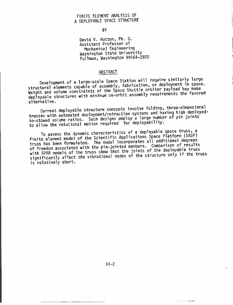
Development of a large-scale Space Station will require similarly largestructural elements capable of assembly, fabrication, or deployment in space.Weight and volume constraints of the Space Shuttle orbiter payload bay makedeployable structures with minimum on-orbit assembly requirements the favoredalternative.
Current deployable structure concepts involve folding, three-dlmensionaltrusses with automated deployment/retraction systems and having high deployed-to-stowed volume ratios. Such designs employ a large number of pin jointsto allow the rotational motion required for deployability.
To assess the dynamic characteristics of a deployable space truss, afinite element model of the Scientific Applications Space Platform (SASP)truss has been formulated. The model incorporates all additional degreesof freedom associated with the pin-jointed members. Comparison of resultswith SPAR models of the truss show that the joints of the deployable trusssignificantly affect the vibrational modes of the structure only if the trussis relatively short.
XX-2
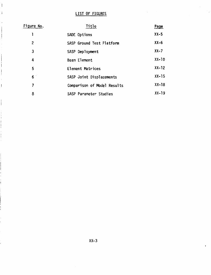
Figure No.
1
2
3
4
5
6
7
8
LIST OF FIGURES
Title
SADE Options
SASP Ground Test Platform
SASP Deployment
Beam Element
Element Matrices
SASP Joint Displacements
Comparison of Model Results
SASP Parameter Studies
Page
XX-5
XX-6
XX-7
XX-IO
XX-12
XX-15
XX-18
XX-19
XX-3
INTRODUCTION
The Scientific Applications Space Platform (SASP} Truss is a deployablethree-dimensional structure designed to be a building-block element in largespace structures. The basic design unit of the SASP truss is a folding cellcomposed of two bays. When fully deployed each bay has the overall dimen-sions of a 1.4 meter cube. Theoretically, any number of cells can be joinedend to end to create a deployable structure of any length. Alternatively,several independent trusses could be joined to create a composite platformin a variety of configurations such as a "T" shape, for example.
The Structural Assembly Demonstration Experiment (SADE), tentativelyassigned to STS 28, includes the objectives of demonstrating shuttle capac-ity to build a large space structure on-orbit and validating truss designincluding deployment, assembly, and connectors. As an integral part ofthree of the five options under consideration for SADE (Figure I), detailedanalysis and testing of the dynamic characteristics of the SASP truss arerequired. For testing deployment characteristics, the SASP ground testplatform (Figure 2) has been fabricated and deployment testing is currentlyunderway. In addition, a mathematical model of deployment was developed byStoll Ill.
As the relatively low natural frequencies of vibration expected of suchlarge structures could affect shuttle control, analysis of the modal char-acteristics of the various SADE options is needed. Subsequent articles ofthis report describe such an analysis for the SASP truss for several con-figurations using two different mathematical models.
THE SASP STRUCTURE
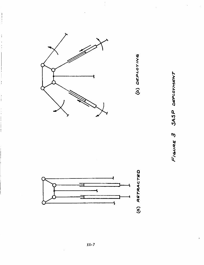
When retracted, the SASP truss resembles a tightly folded accordionwith the longitudinal (longeron), diagonal, and transverse members alignedas depicted in Figure 3a. Deployability of the truss is made possible bythe telescoping design of the main diagonals and the free rotational motionof certain of the structural members at the joints. In the retractionpositions, the length of the telescoping diagonal members is approximately2.6 meters (104 inches). A deployment cable is strung through the diagonalsin sequence and passes across pulleys located at the folding joints and isrigidly attached to the terminal bay of the truss. For depoyment, thecable is reeled in via a motor located at the fixed end of the truss. Thisaction produces shortening and rotation of the telescoping diagonals as inFigure 3b. Simultaneously, the longerons rotate about pin connections(effectively) at each joint, and the transverse members execute pure trans-lation in following the joint motion. In the fully deployed position, alocking mechanism on the telescoping diagonals is mechanically actuated,thus preventing further motion and locking each bay into its three dimen-sional truss configuration.
XX-4

z_w
:;'r-Oe_.
• . ". __.
Z_
o_,,
,// o.
¢flZ0
i--0._0w
ill
,.,_G_L:J" _C_..L,VZ
_-Tx-T...:['__[>. 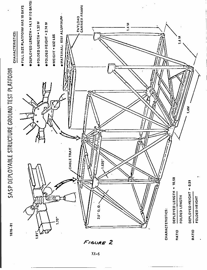
F--
t.l.J
o..._l(3_
.<
I_D
0
W
.J
o
6d
f t_o_. 2
w
I-
_z
o-
° _.°|
Z 3: --I,M
o_ g_.j _ E3
_o _o
0 0m
er
XX-6
Q
Wl
xx-7

The SASP deployment mechanism is a single-fold concept. Telescopingand rotation of structural members occur in a single coordinate plane(actually in two parallel planes). In the two perpendicular planes, thetruss configuration remains the same whether retracted or deployed. Inthese planes, frames designed for payload attachment can be substitutedfor truss members as suggested by Figure 2.
Excepting the longerons, Which are open cross sections designed fornesting, the structural members are 2-inch outside diameter 6061 aluminumtubing having wall thickness of 0.072 inches. Joint fittings, payloadcarrier frames, and cable trays are of the same aluminum alloy. Eachtwo-bay cell is composed of 26 members. Without payload carriers andaccounting for end closure, the ten bay, five cell truss is composed of135 structural members.
PRELIMINARY ANALYSIS
Initially, several models of the SASP truss were formulated and anal-ed using the Structural Performance Analysis and Redesign (SPAR) system]. SPAR is a set of computer programs written for general structural
analysis using the finite element method. The SPAR programs (referredto as processors) utilize sparse matrix techniques [3] which provide highcomputational speed and the capability of analyzing very large structures.Finite elements available include bar, beam, plate, shell, solid, andzero-length pure-stiffness elements. However, for analysis of a deployablestructure such as the SASP truss, the SPAR system provides no reasonablemeans for directly modeling the many pin-jointed members. To illustratethis contention, the SPAR models of the SASP truss will be discussedbriefly.
The most common approach in modeling planar truss structures is totreat the individual members as bar elements which have axial stiffnessonly. Effectively, this approach models all structural joints as pinconnections since bending and torsion are not supported by the stiffnessformulation for bar elements. Consequently, joint rotations are not al-lowed. For structures loaded symmetrically in the plane of the majorload supporting framework, the bar formulation is generally adequate.In the case of the SASP truss, several shortcomings of bar-element model-ing are apparent. In this analysis, we seek the natural frequencies(particularly the fundamental frequency) and mode shapes of forced vibra-tions of the truss in a cantilever configuration. It is not known a priorithat the inertial loading associated with free vibration will occur in aplane or planes parallel to a major structural plane of the truss. Infact, considering the structural complexity of the truss, the likelihoodof this occurrence is thought to be remote. The other objections to barelements are rather obvious: all stiffness and inertia terms associatedwith bending, torsion and shear are ignored in the formulation.
Another possible approach is to model each structural member as athree-dimensional beam element. In this formulation, all stiffness
XX-8

and inertia terms arising from bending and shear in the principal planesare included as are those associated with torsion. For beam-element
modeling, all elements connected to a common joint have identical dis-
placements at the joint location. In the case of the SASP truss, the
major joints connect eight structural members. Only two of the members
are affixed so as to have displacement identical to those of the joint.
Each of the other six has an additional, independent degree of freedomallowed by a pin connection at the joint. A similar situation exists at
the smaller joints as well. Thus, straightforward beam-element modeling
may result in overspecified stiffness and could give vibrational frequen-
cies which are too large. It may be possible, using SPAR's zero-length,
stiffness-only element capability, to produce joint models which more
adequately simulate the actual joint construction of the deployable truss.
This possibility was given a cursory examination but not pursued in-depth
as it appeared to require an excessively large number of joints.
Although several objections to SPAR models of the SASP truss have
been delineated above, computer runs using such models have been obtained.
These results will be used for comparison with those of a SASP-uniquemodel to be discussed in the next article.
SASP FINITE ELEMENT MODEL
In order to capture, as accurately as possible, the modal vibration
characteristics of the SASP truss, a finite element model of the structure
has been developed from scratch. Hereafter referred to as SFEM, this model
formulation incorporates all additional degrees of freedom associated with
the many pin joints in the structure.
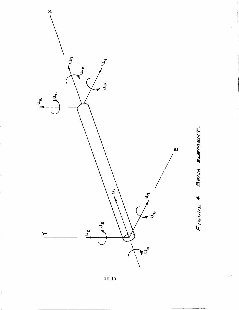
In SFEM, each structural member of the SASP truss is treated as a
three-dimensional beam element, as in Figure 4. With each element isassociated an element reference frame xyz as shown, and the stiffness and
inertia properties of the element are defined in terms of this frame.
Generalized displacements uI through Ul2 represent the three displacementsand three rotations of each-end of the beam. The element reference frame is
assumed to be oriented such that bending is referred to the principal planes
of bending.
The stiffness and inertia properties of the beam element are obtained
by considering the potential and kinetic energies of the element in con-
junction with sh__hapefunctions S(x) which describe the displacement of anypoint x along the be_ _-ni-e-rmsof the displacements at the end of the beam.
For axial displacement, for example, we write
(1)
where the shape functions (also known as assumed modes) must satisfy the
boundary conditions
XX-9
>-.
:::r
_Q
b.
XX-lO
(2)
in order to satisfy u (o,t) = up(t) and u (L,t) = u7 (t). The ap-
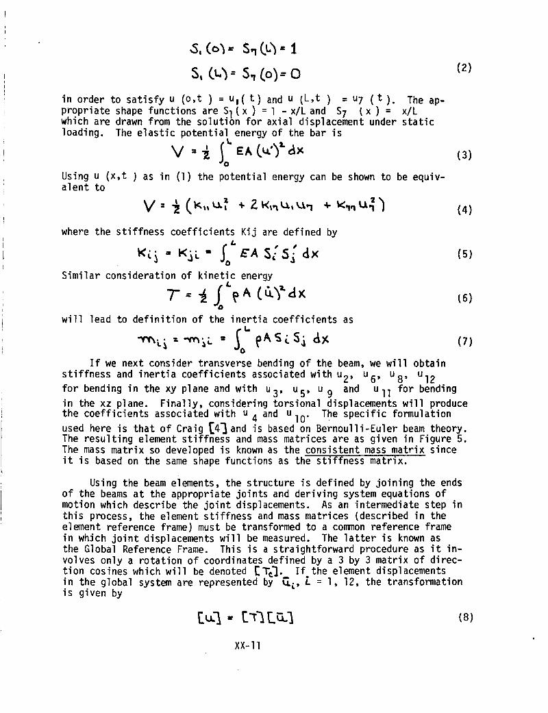
propriate shape functions are Sl(X) =l -x/Land S7 (x) = x/Lwhich are drawn from the soluti6n for axial displacement under static
loading. The elastic potential energy of the bar is%,
V - IoEA axUsing u (x,t) as in (1) the potential energy can be shown to be equiv-alent to
(3)
(4)
where the stiffness coefficients Kij are defined by
" EA S[ ax
Similar consideration of kinetic energyL
will lead to definition of the inertia coefficients as
(5)
(6)
(7)
If we next consider transverse bending of the beam, we will obtain
stiffness and inertia coefficients associated with u 2, u6, u8, Ul2
for bending in the xy plane and with u 3, u 5, u 9 and Ull for bending
in the xz plane. Finally, considering torsional displacements will produce
the coefficients associated with u 4 and u 10" The specific formulation
used here is that of Craig [4] and is based on Bernoulli-Euler beam theory.
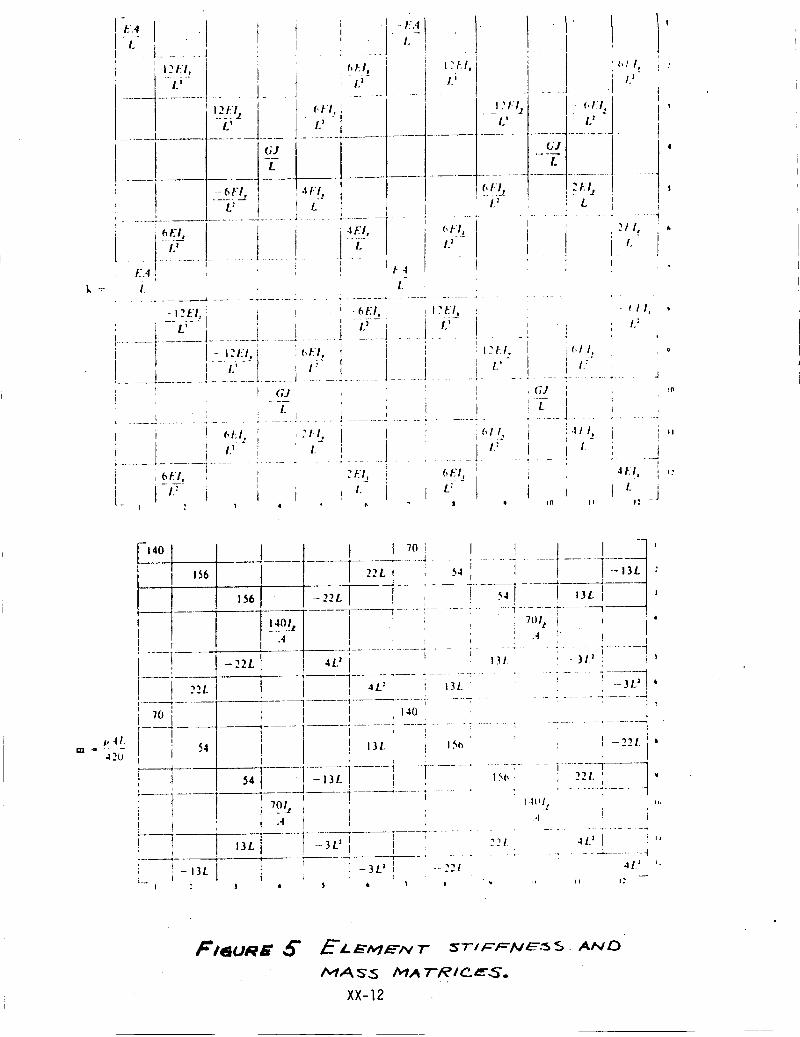
The resulting element stiffness and mass matrices are as given in Figure 5.
The mass matrix so developed is known as the consistent mass matrix since
it is based on the same shape functions as the stiffness matrix.
Using the beam elements, the structure is defined by joining the ends
of the beams at the appropriate joints and deriving system equations of
motion which describe the joint displacements. As an intermediate step in
this process, the element stiffness and mass matrices (described in the
element reference frame) must be transformed to a common reference frame
in which joint displacements will be measured. The latter is known as
the Global Reference Frame. This is a straightforward procedure as it in-
volves only a rotation of coordinates defined by a 3 by 3 matrix of direc-
tion cosines which will be denoted [T:]. If the element displacementsin the global system are represented by _, i = l, 12, the transformationis given by
(8)
XX-ll
/:.4
12FI,.-L_-
t l2FI z--L;
I,t'l,L_ -
-- 6/:'!, 4/I,---L_-- I L
i
fiEI,
L z
. - EAI.
I ?t: I,L j
, I......... + ........................ , .....
,
....!....-G-!" I
21/,L-_t_ i 4r.I, ,,_.r, J
I
E.4, _ t.4
Z L-......... _ .............. . ....... . ........ -, ...................
- _:t/, i _ _ :_(,%! i I:_./,', i --L _-- ] I I.' L_-!......i........!..........I....4 ......: .......1 ... JI t I - 12/:1J . _,_l I ', : _:t:/.
I I i,"l t IL,• -i; --'........................ L ................................ J ........! ', I GJ * ' lt
I
, f, ll,I I/"I
, GJ
I
, ?
_,11,I.:
i i)
.1
10
, - --- I t "---
' t I , ; I • _ '1 I - ,hi, i . I I, I _ _,1 I, _ 4t I,
i _ : I? i I. i / I." I.; .... 1..... i ........ : ..... : . . .! ..... 1 ....... 1 ...... _ . ..]
---- i I?
i_ I'-: i _ i /- i i t_-- i L iI _ I 4 t, II Q I(I II I_ ""
_.ILm _ 42u
|
-22L
54
............ i .........221. 41) "' . : .... _ ........
--221. 41) ', _--13L
2
13/. -3L _
F/_uR_ 5"
XX-12
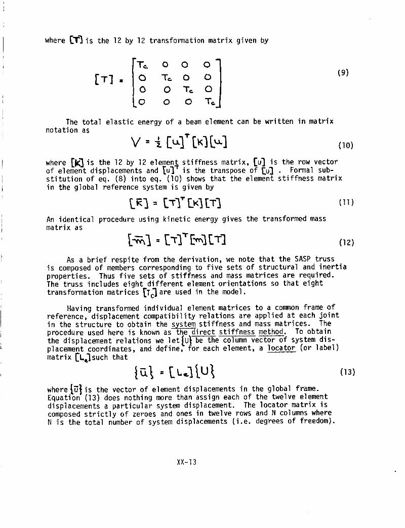
where [T'_ is the 12 by 12 transformation matrix given by
IT] •
"T: O O O"
O T_. 0 0
0 0 T= 0
o o o T _j
{9)
The total elastic energy of a beam element can be written in matrixnotation as
v --- [,.,.1" (10)
where [k] is the 12 by 12 element stiffness matrix, [u] is the row vectorof element displacements and Iu'_ "r is the transpose of [u] Formal sub-stitution of eq. (8) into eq. (I0) shows that the element stiffness matrixin the global reference system is given by
tRI = [%'[KItTIAn identical procedure using kinetic energy gives the transformed massmatrix as
(II)
(12)
As a brief respite from the derivation, we note that the SASP trussis composed of members corresponding to five sets of structural and inertiaproperties. Thus five sets of stiffness and mass matrices are required.The truss includes eight different element orientations so that eight
transformation matrices _Tc]are used in the model.
Having transformed individual element matrices to a common frame ofreference, displacement compatibility relations are applied at each jointin the structure to obtain the _stiffness and mass matrices. Theprocedure used here is known as the direct stiffness method. To obtain
the displacement relations we let{U_ be the column vector of system dis-placement coordinates, and define, for each element, a locator (or label)
matrix [L¢Isuch that
where {_} is the vector of element displacements in the global frame.Equation (13) does nothing more than assign each of the twelve element
displacements a particular system displacement. The locator matrix is
composed strictly of zeroes and ones in twelve rows and N columns whereN is the total number of system displacements (i.e. degrees of freedom).
XX-13
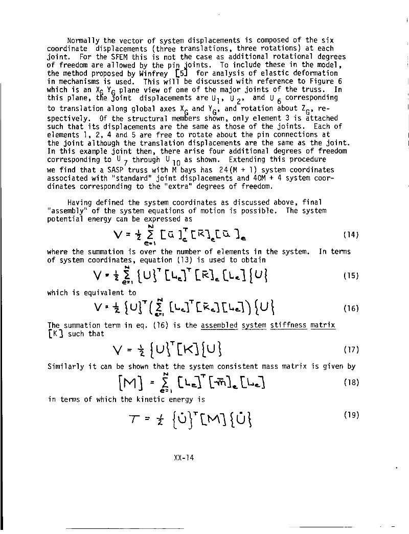
Normally the vector of system displacements is composedof the sixcoordinate displacements (three translations, three rotations) at eachjoint. For the SFEMthis is not the case as additional rotational degreesof freedom are allowed by the pin joints. To include these in the model,the method proposed by Winfrey [5] for analysis of elastic deformationin mechanismsis used. This will be discussed with reference to Figure 6which is an XGYGplane view of one of the major joints of the truss. Inthis plane, tile joint displacements are UI, U2' and U6 correspondingto translation along global axes XG and YG' and rotation about ZG, re-spectively. Of the structural membersshown, only element 3 is attachedsuch that its displacements are the sameas those of the joints. Each ofelements I, 2, 4 and 5 are free to rotate about the pin connections atthe joint although the translation displacements are the sameas the joint.In this example joint then, there arise four additional degrees of freedomcorresponding to U7 through UI0 as shown. Extending this procedurewe find that a SASPtruss with M bays has 24(M + I) system coordinatesassociated with "standard" joint displacements and 40M+ 4 system coor-dinates corresponding to the "extra" degrees of freedom.
Having defined the system coordinates as discussed above, final"assembly" of the system equations of motion is possible. The systempotential energy can be expressed as
where the summationis over the numberof elements in the system.of system coordinates, equation (13) is used to obtain
N
v- [u.1"[at<[u l lulwhich is equivalent to
The summation term in eq. (16) is the assembled system stiffness matrixIN] such that
(14)
In terms
(15)
(16)
(17)
Similarly it can be shown that the system consistent mass matrix is given byN -1.
in terms of which the kinetic energy is
XX-14

L)
3
FI&IJRE _ ,.,_A_P ::T'OIN'[ 131$PLACEIVIENT,$.
XX-15

By using eqs. (17) and (19) we obtain the system equations of motion inthe matrix form
I:: 1 • [K1 o (20)
Equation 120) results from application of Hamilton's principle or by form-ing the Lagrangian and differentiating. Solution of the Eigenvalue problemrepresented by (20) will yield the natural frequencies and mode shapes offree vibrations of the truss structure.
DISCUSSION OF RESULTS
For simplicity, the SFEM was first applied to a single-cell, two-baytruss composed of 31 elements and constrained in a cantilever configuration.The resulting structural model has 92 active degrees of freedom after elim-inating 24 displacements via the constraint conditions. Computer programswere written to sequentially calculate the element stiffness and mass mat-rices, transform the matrices to the global coordinate system, and assemblethe system_matrices, qAs pointed out by Craig, the matrix multiplicationsinvolving [_'_and ILia'do nothing more than locate terms from the elementmatrices into the proper row and column of the corresponding system matrix.To accomplish this and avoid a great number of matrix multiplications in-volving mostly zeroes, a locator vector was used for each element. Thisvector contains simply the row-column data relating element matrix tosystem matrix.
After assembly of the system matrices, the Eigenvalue problem wassolved using the FORMA [6]matrix subroutine package. The results of thefirst SFEM run gave the fundamental frequency of the two-bay SASP trussas 27.9 Hz. For comparison, a SPAR model of the two-bay truss, usingidentical elements, resulted in a fundamental frequency of 50.6 Hz. Thisapparently significant difference in results was not accepted without con-siderable double checking of the model formulation and the computer program.By eliminating the "extra" degrees of freedom, the SFEM programs should pro-duce the same results as SPAR. When this was done, the first six naturalfrequencies of the two models were found to differ by less than one percent.On this basis, the accuracy of SFEM was established.
Extending SFEM to the full size ten-bay truss required considerablerework of the computer programs. The ten-bay truss is composed of 135structural members which leads to 444 degrees of freedom for the model.The huge matrices involved with a model of this magnitude are not amenableto routine manipulation as the computer time and storage requirements areastronomical. To assuage these difficulties, all matrix operations wereconverted to partition logic to eliminate storage and manipulation ofvast number of zero terms. This conversion was readily accomplished sinceNASA's ZFORMA subroutine package could be used directly. These routinespartition all matrices into 60 by 60 (maximum) submatrices for both stor-age and algebraic manipulation. Using subroutine ZMODEI to solve theEigenvalue problem, the two lowest natural frequencies of the ten-bay
XX-16
truss were determined _n about eight minutes of actual computer time.The fundamental frequency so determined is 4.6 Hz while the second
frequency is 5.4 Hz. Again for comparison, results from a ten-bay
model using the SPAR system were obtained. To the surprise of the
investigator, the frequencies from the SPAR model were substantially
identical. Having learned years ago to believe and disbelieve simul-
taneously, the investigator again proceeded to check and double check.
The partition-logic programs were reduced to the two-bay model to de-tect software errors which could have arisen in conversion. The results
were identical to those previously obtained. On this basis, the ten-bayresults were accepted as correct also.
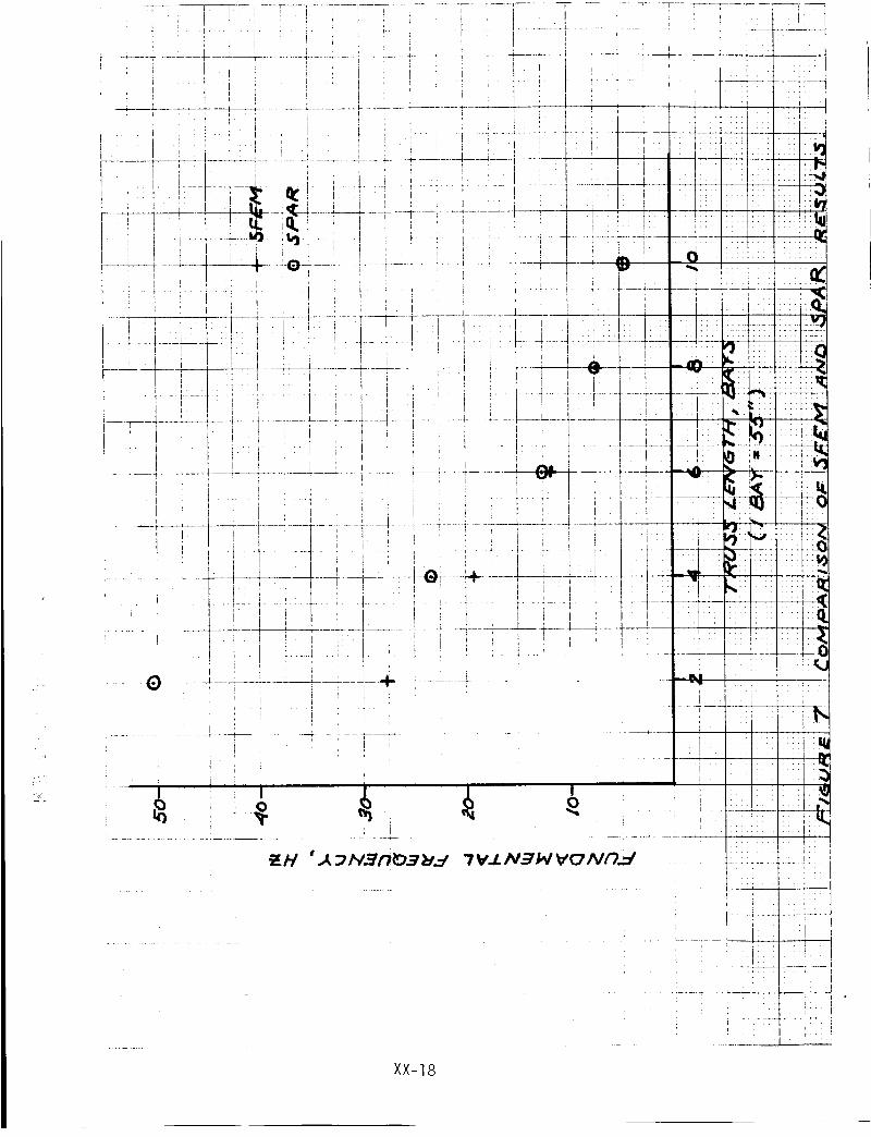
Based on the contradictory comparisons of two-bay and ten-bay trussmodels using SFEM and SPAR, the programs for each model were run for
four-, six-, and eight-bay truss configurations. The results of these
runs, as shown by Figure 7, show that the fundamental frequencies given
by the two models are convergent with respect to overall truss length.Since the major difference in SFEM and the SPAR model lies in the ef-
fective rotational stiffness of the joints, this phenomena can only be
explained by surmising that the effects of joint rotations are reduced
with increasing truss length not unlike the decreasing significanceof transverse shear versus length of a beam.
Per the request of R. E. Jewell (MSFC/ED21), fundamental frequencies
of the SASP structure were obtained for truss lengths up to 50 bays(230 feet) and for the ten-bay truss with concentrated mass at one end.
In each of these additional cases the cantilever constraint was retained
so the length cases apply to SADE Options Ill and IlIA while the tip mass
cases are applicable to Option IA. Fundamental frequency versus truss
length as given by SPAR models is shown in Figure 8a. The results of
frequency as a function of tip mass are as in Figure 8b. The latter
results were again in agreement from both SFEM and SPAR.
CONCLUSIONS AND RECOMMENDATIONS
A detailed finite element analysis of the SASP deployable truss has
shown that the fundamental frequencies of vibration are not significantly
affected by the extra degrees of freedom associated with the many pin-
pointed members except for short overall truss lengths. This leads to
the conclusion that simplified models utilizing the SPAR system can beused to adequately assess the dynamic characteristics of the structure
for the configurations being considered for SADE.
As additional deployable truss designs evolve or composite platformconfigurations using SASP are considered, it is recommended that similar
analyses be conducted to insure accuracy of simplified models. Detailed
modeling similar to SFEM may be required if, in the latter case, a plat-
form concept includes short truss sections to connect payloads for example.
XX-17
_,,z,
i i i
...._ "._ ,_ _ ,.o
...... _.__J----
............... I
XX-]8

I
,j :l: .....
XX-19

REFERENCES
l •
o
•
°
So
.
Stoll, H. W•, "Computer Simulation for Dynamic Analysis of aDeployable Space Structure", Final Report, Contract No. NAS8-34506,September 1981.
SPAR Structural Analysis System Reference Manual, NASA CR158970-2,1978.
Whetstone, W. D., "Computer Analysis of Large Linear Frames",Journal of the Structures Division, ASCE, November 1969.
Craig, Roy R., Jr., Structural Dynamics, John Wiley and Sons,New York, 1981.
Winfrey, Richard C., "The Finite Element Method as Applied toMechanisms", Finite Element Applications in Vibration Problems,ASME, New York, 1977.
Expansion and Improvement of the FORMA System For Response andLoad Analysis, MCR-76-217, Martin-Marietta, May 1976.
XX-20