1980 Suzuki GS850GT Stator Replacement – by … · 1980 Suzuki GS850GT Stator Replacement – by...
16
1980 Suzuki GS850GT Stator Replacement – by BassCliff (a.k.a.BikeCliff) Greetings to those of you who ride the classic GS series motorcycles from Suzuki. This documents my first experience replacing my stator. This procedure will be very similar for other GS series bikes, but be sure to refer to your bike’s service manual before proceeding. For a thorough background on the charging systems of the Suzuki GS series motorcycles, see “The Stator Papers” in the GSR Forum at http://www.thegsresources.com/garage/gs_statorfacts.htm . The GS Resources Forum is an excellent web community dedicated to keeping these classic bikes on the road. Visit or join at http://www.thegsresources.com . And now, on with the show! Let’s begin by disconnecting the positive terminal of the battery (or removing the battery altogether) and draining the oil. I happened to need an oil/filter change at the same time I was replacing my stator so the timing worked nicely. Some riders will just lean their bikes to the right, against something stable, so that when the left crankcase cover is removed no oil will drain out. Here is the left crankcase cover gasket. I’m holding it upside down, sorry. This is part number 477686-001. (Before we go much farther, let me apologize for the filthy condition of my bike. I’ve been a little neglectful lately. But now that she’s running better I’ll get her cleaned up.) Moving on…
Transcript of 1980 Suzuki GS850GT Stator Replacement – by … · 1980 Suzuki GS850GT Stator Replacement – by...

1980 Suzuki GS850GT Stator Replacement – by BassCliff (a.k.a.BikeCliff)
Greetings to those of you who ride the classic GS series motorcycles from Suzuki. This documents my first experience replacing my stator. This procedure will be very similar for other GS series bikes, but be sure to refer to your bike’s service manual before proceeding. For a thorough background on the charging systems of the Suzuki GS series motorcycles, see “The Stator Papers” in the GSR Forum at http://www.thegsresources.com/garage/gs_statorfacts.htm . The GS Resources Forum is an excellent web community dedicated to keeping these classic bikes on the road. Visit or join at http://www.thegsresources.com .
And now, on with the show!
Let’s begin by disconnecting the positive terminal of the battery (or removing the battery altogether) and draining the oil. I happened to need an oil/filter change at the same time I was replacing my stator so the timing worked nicely. Some riders will just lean their bikes to the right, against something stable, so that when the left crankcase cover is removed no oil will drain out.
Here is the left crankcase cover gasket. I’m holding it upside down, sorry. This is part number 477686-001.
(Before we go much farther, let me apologize for the filthy condition of my bike. I’ve been a little neglectful lately. But now that she’s running better I’ll get her cleaned up.)
Moving on…

Remove the left crankcase cover bolts (below). My bike still has the original phillips head bolts. They need a few taps from my impact driver to loosen them up. If I would’ve planned ahead they would be replaced with new hex head bolts. But alas, that will have to wait.
In the picture below, the cover is loose and hanging. At this point you may wish to just cut the stator wires but I chose to pull everything out intact.
If the magnetic force is strong enough, it may take a rubber mallet to encourage the case to come off. I also want to mention that the bolts are not all the same and must go back into their original holes. I started with the topmost bolt and removed them in a clockwise fashion, lined them up in order, so that I could put them back into their proper places during reassembly.

Next I removed the starter cover. This is held on by a couple of 10mm bolts. It should be very easy to remove, if you have a small enough wrench to get to the back bolt.
Here is a view of the starter cover removed and the crankcase cover hanging loose by the wires. I reused the starter cover gasket.
If you look closely above you can see the old stator wire bundle. The wire just lays along the right side of the starter then exits through the slot in the back. It is held in place with a “bendy” clip on top of the crankcase below the carburetors.

This is an internal view of the left crankcase cover, before I removed the wiring and disassembled it.
On my bike, if you follow the old stator wires back to where they connect to the r/r (regulator/rectifier) under the left side cover, you will see this mess.
This is where my “new” Honda r/r is connected (via bullet connectors) to the old stator. The Honda r/r “upgrade” is well-documented in the GSR Forum Tech Section. You can see where I had taped and zip-tied the connections to insulate the bare connectors. You can also see the old stator wires (on the left side of the connections) have overheated and discolored the insulation. The new bright yellow wires on the right side of the connections lead to the new r/r. Note that you can connect the three yellow stator wires to the three yellow r/r wires in any order.

Here is a shot of the old stator. Notice that a few of the coils have damaged insulation, effectively turning them into a big hunk of copper resistance instead of a current-producing coil. Two of these coils were on the same leg of the stator. No wonder it wasn’t charging.
I used a straight edge razor blade to remove the old gasket. Then I scrubbed a little with some fine steel wool to remove the residue. Be careful not to leave any steel wool particles in the cover when you reassemble.
You can’t see it too well in the picture above – there’s a better view in the picture below of a small tube-shaped grommet that fits in one of the larger screw holes (look below the razor blade in the picture above, or above the screwdriver in the picture below). Take care not to lose this piece if/when it falls out. Just put it back when you place the new gasket on the cover during reassembly.
I removed the stator screws and the wire guides. These may be pretty snug and also require a few light taps with the impact driver.
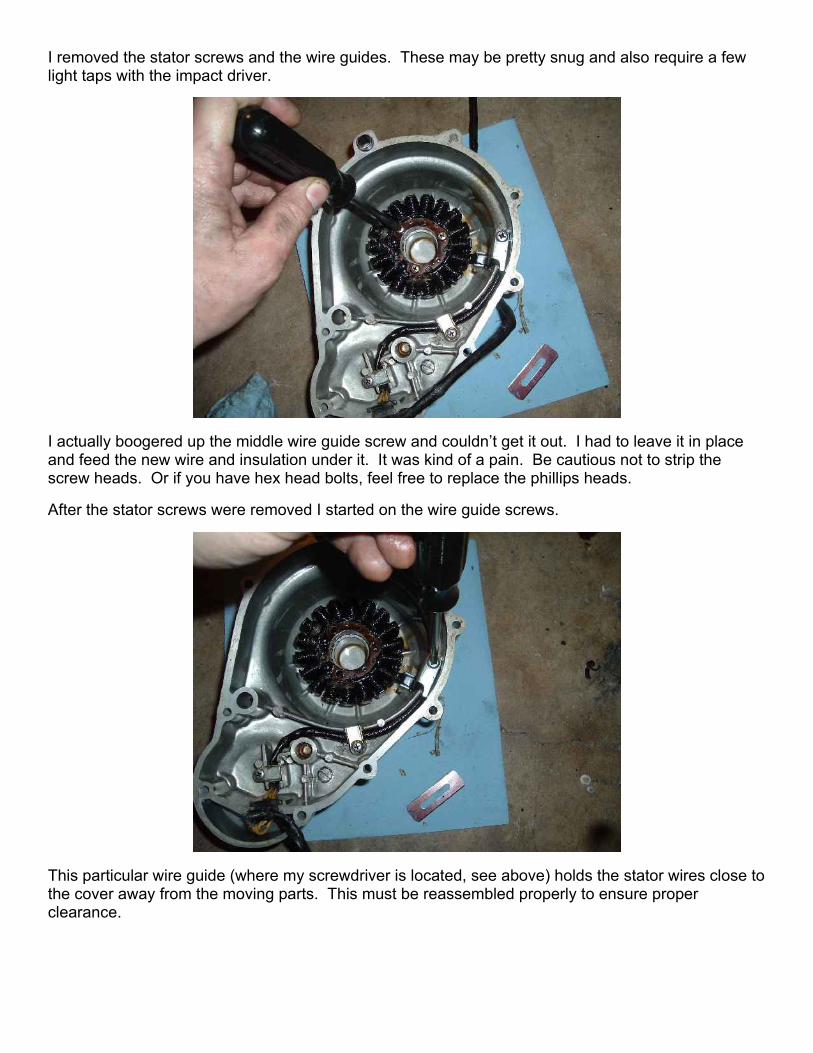
I actually boogered up the middle wire guide screw and couldn’t get it out. I had to leave it in place and feed the new wire and insulation under it. It was kind of a pain. Be cautious not to strip the screw heads. Or if you have hex head bolts, feel free to replace the phillips heads.
After the stator screws were removed I started on the wire guide screws.
This particular wire guide (where my screwdriver is located, see above) holds the stator wires close to the cover away from the moving parts. This must be reassembled properly to ensure proper clearance.
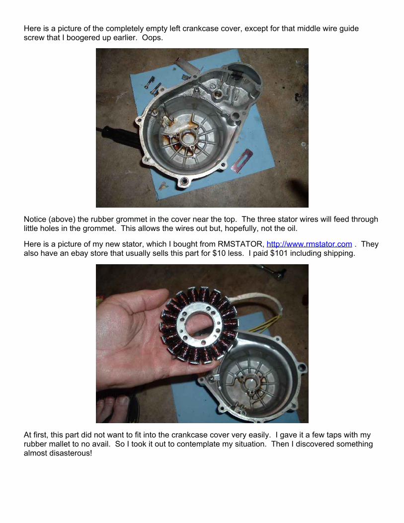
Here is a picture of the completely empty left crankcase cover, except for that middle wire guide screw that I boogered up earlier. Oops.
Notice (above) the rubber grommet in the cover near the top. The three stator wires will feed through little holes in the grommet. This allows the wires out but, hopefully, not the oil.
Here is a picture of my new stator, which I bought from RMSTATOR, http://www.rmstator.com . They also have an ebay store that usually sells this part for $10 less. I paid $101 including shipping.
At first, this part did not want to fit into the crankcase cover very easily. I gave it a few taps with my rubber mallet to no avail. So I took it out to contemplate my situation. Then I discovered something almost disasterous!

I guess I had been handling the stator a bit to roughly. A couple of wires had come loose, broken off from the windings! Egads!
For a moment I was dazed and confused. But then I realized that it was an easy fix. A cold solder joint can be brittle and I decided I would just resolder the connections. I clipped off the strain relief zip tie, pulled the white insulating cover back to expose the already-tinned ends, and resoldered the yellow wires back onto the copper winding wires where necessary. I put on a fresh zip tie for strain relief and life was good again!
This part came with a black insulating cover which I used to cover the white insulating you see above. I also zip tied the black outer insulation to keep it in place. I cut a piece of the black insulating just long enough to cover the wires from the strain relief to the rubber grommet inside the cover, as you will later see. I used the rest to cover the wires on the other side of the grommet, the part that runs through the starter cavity.
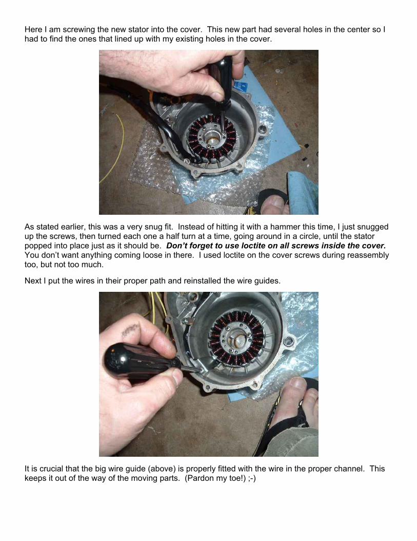
Here I am screwing the new stator into the cover. This new part had several holes in the center so I had to find the ones that lined up with my existing holes in the cover.
As stated earlier, this was a very snug fit. Instead of hitting it with a hammer this time, I just snugged up the screws, then turned each one a half turn at a time, going around in a circle, until the stator popped into place just as it should be. Don’t forget to use loctite on all screws inside the cover. You don’t want anything coming loose in there. I used loctite on the cover screws during reassembly too, but not too much.
Next I put the wires in their proper path and reinstalled the wire guides.
It is crucial that the big wire guide (above) is properly fitted with the wire in the proper channel. This keeps it out of the way of the moving parts. (Pardon my toe!) ;-)

This is a picture of the rubber grommet through which the yellow stator wires pass. It can be a pain to thread the wires though. A little lubrication may be necessary. Mine had been cut and then glued back together by a previous (lazy) mechanic. Had I known I would have ordered a new part.
Pictured below is the completed assembly, ready for a gasket and bolting onto the crankcase. I used zip ties to hold the insulation in place.
The black insulation covering I received with the part wasn’t quite long enough. So I removed the insulation from the old stator wires to augment the new stuff. I again placed a zip tie where the old insulation slid under the new insulation to hold them both in place.

Here I have threaded the wires though the opening that leads to the starter cavity and I’m about to place the cover (and gasket) back in place.
I was a little startled when, while lining up the cover, it jumped out of my hands back onto the crankcase. That’s a pretty strong magnetic effect! If you have a couple of old, long screws that fit you can use them as guides for the cover. Cut screwheads off, put one screw at each end of the case, and slide the cover on. When the magnet grabs it, it will be lined up in place.
In the picture below I’m snugging up the cover screws. After I got them all pretty snug with my screwdriver I went back and gave them a couple of taps with my impact driver. I used some medium loctite on the cover screws to guard against loosening from vibration.
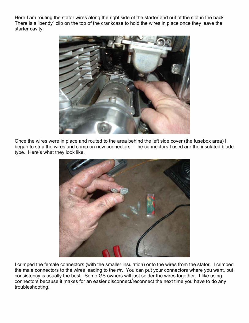
Here I am routing the stator wires along the right side of the starter and out of the slot in the back. There is a “bendy” clip on the top of the crankcase to hold the wires in place once they leave the starter cavity.
Once the wires were in place and routed to the area behind the left side cover (the fusebox area) I began to strip the wires and crimp on new connectors. The connectors I used are the insulated blade type. Here’s what they look like.
I crimped the female connectors (with the smaller insulation) onto the wires from the stator. I crimped the male connectors to the wires leading to the r/r. You can put your connectors where you want, but consistency is usually the best. Some GS owners will just solder the wires together. I like using connectors because it makes for an easier disconnect/reconnect the next time you have to do any troubleshooting.
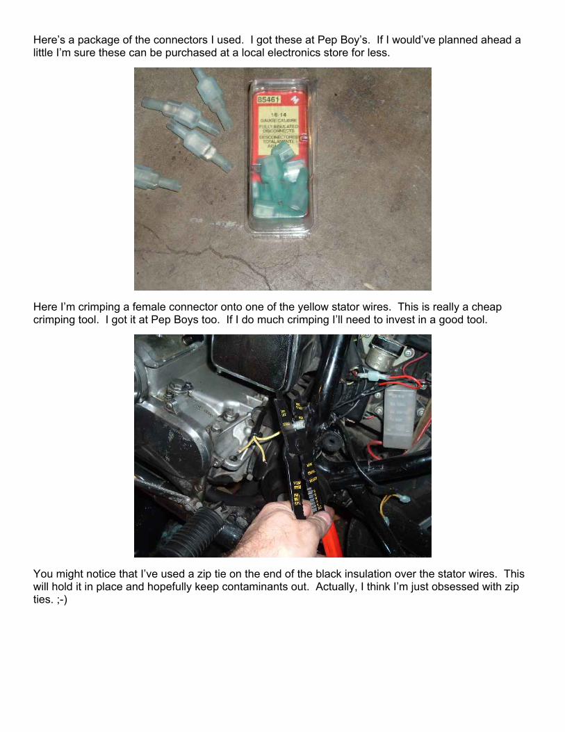
Here’s a package of the connectors I used. I got these at Pep Boy’s. If I would’ve planned ahead a little I’m sure these can be purchased at a local electronics store for less.
Here I’m crimping a female connector onto one of the yellow stator wires. This is really a cheap crimping tool. I got it at Pep Boys too. If I do much crimping I’ll need to invest in a good tool.
You might notice that I’ve used a zip tie on the end of the black insulation over the stator wires. This will hold it in place and hopefully keep contaminants out. Actually, I think I’m just obsessed with zip ties. ;-)

Here is a picture of the bullet connectors coming from the Honda r/r (that I purchased from Mr. duaneage, who is a member of the GSR Forums).
I cut off these connectors, used my cheap crimper/stripper tool to strip the ends, and crimped on new male connectors. I’ve heard that these type connectors work better than the bullet connectors. We’ll see. Time will tell. But I think they look good. That’s what’s important, right?
Above, in the background you can see the red wire from the r/r got a new connector too, along with the hot wire from the bike’s wiring harness. The black sense wire from the Honda r/r kept the original bullet connectors since it’s tied into the rear brake light switch. You can see the black sense wire going off to the right and disappearing next to the bundle of orange and yellow wires.
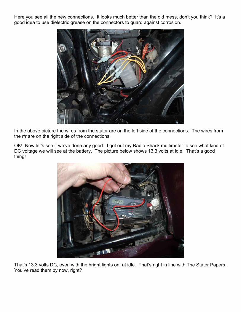
Here you see all the new connections. It looks much better than the old mess, don’t you think? It's a good idea to use dielectric grease on the connectors to guard against corrosion.
In the above picture the wires from the stator are on the left side of the connections. The wires from the r/r are on the right side of the connections.
OK! Now let’s see if we’ve done any good. I got out my Radio Shack multimeter to see what kind of DC voltage we will see at the battery. The picture below shows 13.3 volts at idle. That’s a good thing!
That’s 13.3 volts DC, even with the bright lights on, at idle. That’s right in line with The Stator Papers. You’ve read them by now, right?

Here we see 15 volts DC at the battery when revving to 4000 rpm. This may be a little on the high side, but not overly so. Plus it goes down close to 14.4v when revving higher than 4000rpm. I’ll keep an eye on it for a while, but I think that’s close enough.
Here is what my new wiring bundle looks like when it all neatly cleaned and dressed.
You should have seen this when I first bought the bike. The insulation on the wires was charred and cracked like it had seen a good deal of overheating. Now that I’ve replaced two of the major components in the charging system (r/r and stator), next I’d like to install a new AGM battery. These batteries require no service and are completely sealed. No more leaking acid like you saw on my multimeter pictures.
And so ends another chapter in the maintenance of my bike. I hope this helps other new motorcycle mechanics. Many thanks to Ms. SqDancerLynn1 and Mr. IanFrancisco, also of the GSR Forums, for their help and encouragement. – (Bass)Cliff