
1967 , Volume , Issue May-1967 - HP Labs
20
HEWLETT-PACKARDJOURNAL MAY1967 © Copr. 1949-1998 Hewlett-Packard Co.
Transcript of 1967 , Volume , Issue May-1967 - HP Labs

HEWLETT-PACKARD JOURNAL
MAY 1967 © Copr. 1949-1998 Hewlett-Packard Co.

Pinpointing Industrial Defects with Ultrasonic Ears Gas leaks , co rona , and o ther de fec ts in indus t r ia l e q u i p m e n t c a n b e l o c a t e d q u i c k l y b y z e r o i n g i n o n t h e i r h i g h - f r e q u e n c y s o u n d s . U l t r a s o n i c t r a n s l a t o r s a l l o w m e n t o h e a r a n d f o l l o w t h e s e n o r m a l l y i n a u d i b l e s o u n d s .
By Robert L. Al len
SOUNDS AUDIBLE TO THE BEST HUMAN EARS lie in a frequency range of about 20 Hz to 20 kHz. But
acoustical energy is by no means limited to this range. Just as the human eye responds to only a small portion of the electromagnetic spectrum, the human ear provides man with only a part of the information that could be extracted from sonic energy.
5 0 1 0 0 5 0 0 1 0 0 0 2 0 0 0 5 O O O 1 0 . 0 0 0 2 0 . 0 0 0
F R E Q U E N C Y ( H z )
Minimum sound pressure that can
be heard by the best human cars.
Sonic energy at frequencies above 20 kHz, i.e. ultra
sonic energy, is generated by many common occurrences. For example, rubbing the hands together creates high- frequency sounds at about 40 kHz that can be heard by a dog or cat at a distance of 50 feet. Sibilant sounds in speech are also a source of ultrasonic energy. Another well-known producer of high-frequency sounds is the bat, which navigates by bouncing ultrasonic 'beeps' off nearby objects. Bat 'beeps' contain frequencies up to 150 kHz.
Many phenomena in industry also produce ultrasonic energy. Some of the stronger producers are defects like gas leaks, corona, vibrations, and friction. These defects induce random irregular motions in surrounding mole cules, so the sonic energy they produce is spread over a wide range of frequencies. In many cases a defect can be recognized by its high-frequency sounds long before it worsens to a point where it becomes audible.
Ultrasonic Translators
A simple, yet effective means for human ears to hear the ultrasonic world is the ultrasonic translator, first developed in 1961 by what is now the Delcon Division of -hp-. -hp- ultrasonic translators convert high-fre quency sounds at frequencies between approximately 36 kHz and 44 kHz to audible sounds at frequencies less than 5 kHz, where human ears are most sensitive (see diagram at left). Unlike some ultrasonic test equip ment, translators are not generators of ultrasonic energy.
' B e s i d e s u l t r a s o n i c t r a n s l a t o r s , t h e D e l c o n D i v i s i o n a l s o p r o d u c e s i n s t r u m e n t s f o r ¡ocat i r .g cp t r c i rcu i ts in cab les s r . i fo r !cc :à : r ;g fsuüc in b ' j r i?d cab les .
© Copr. 1949-1998 Hewlett-Packard Co.

TRANSDUCER 3 6 - 4 4 k H z
MIXER
LOCAL OSCILLATOR
40 kHz
O- 4 kHz Speaker o r Earphones
Basic ultrasonic translator block diagram.
They translate; that is, they make it possible to listen to sounds that are normally inaudible.
Translator operation is relatively uncomplicated. At the top of this page is a basic block diagram. Ultrasonic energy between 36 kHz and 44 kHz is converted to elec trical signals of the same frequencies by a high-frequency microphone, located in a cylindrical probe. The electrical signals are amplified and heterodyned with a 40-kHz local oscillator signal, and the resulting signals are filtered to eliminate all frequencies above 5 kHz. The audio frequency signals are connected to a loudspeaker or to earphones, or rectified and applied to a meter.
Translators have speeded and simplified the detection and location of many different kinds of ultrasonic sources. There are several reasons for their effectiveness.
First, the probes are directional, giving maximum response when they are pointed directly at a source of ultrasonic energy. It is easy to learn to locate a source by coordinating its direction with the intensity of the trans lator output.
Second, the high-frequency noises of many defects which are too small to make audible noises, when trans lated, sound very much like the audible sounds these defects would produce if they were larger and more serious. For example, the translated sound of a gas leak is a hissing noise, and a dry bearing makes high-fre quency sounds which translate into a high-pitched squeal. Hence it is easy to identify the translated sounds of most common defects.
A third reason why translators are effective is that they are fast. It isn't necessary to dismantle anything to
Airline mechanic checks Boeing 720B cabin oxygen sys
tem for leaks using -lip- Model 118 Ultrasonic Translator
and general-purpose probe with focusing extension.
© Copr. 1949-1998 Hewlett-Packard Co.
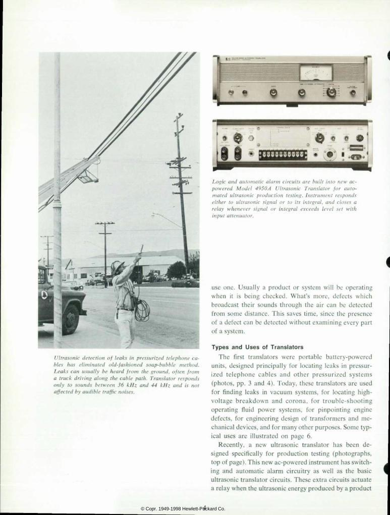
Ultrasonic detection of leaks in pressurized telephone ca
bles has el iminated old-fashioned soap-bubble method.
Leaks can usually be heard from the ground, often from
a truck driving along the cable path. Translator responds
on ly to sounds be tween 36 kHz and 44 kHz and i s no t
affected by audible traffic noises.
Logic and automatic alarm circuits are built into new ac-
powered Model 4950A Ul trasonic Trans la tor for auto
mated ultrasonic production testing. Instrument responds
either to ultrasonic signal or to its integral, and closes a
relay whenever signal or integral exceeds level set with
input attenuator.
use one. Usually a product or system will be operating when it is being checked. What's more, defects which broadcast their sounds through the air can be detected from some distance. This saves time, since the presence of a defect can be detected without examining every part of a system.
T y p e s a n d U s e s o f T r a n s l a t o r s The first translators were portable battery-powered
units, designed principally for locating leaks in pressur ized telephone cables and other pressurized systems (photos, pp. 3 and 4). Today, these translators are used for finding leaks in vacuum systems, for locating high- voltage breakdown and corona, for trouble-shooting operating fluid power systems, for pinpointing engine defects, for engineering design of transformers and me chanical devices, and for many other purposes. Some typ ical uses are illustrated on page 6.
Recently, a new ultrasonic translator has been de signed specifically for production testing (photographs, top of page). This new ac-powered instrument has switch ing and automatic alarm circuitry as well as the basic ultrasonic translator circuits. These extra circuits actuate a relay when the ultrasonic energy produced by a product
© Copr. 1949-1998 Hewlett-Packard Co.

under test exceeds a preset level. The relay can be used to set off an alarm or to cause a faulty product to be rejected.
Detec t ing Low-pressure Gas Leaks
Of historical as well as practical significance, because it was one of the earliest applications of ultrasonic transla tion, is the detection and location of leaks in pressurized telephone cables. Pressurization of long-distance cables was begun by the telephone company in 1927, and sub scriber cables were first pressurized in 1952. Cable pressurization prevents moisture from penetrating the cable in the event of a break in the cable sheath. It has been found to substantially reduce the number of service- affecting cable troubles. Dry air circulating in the cable keeps the insulating paper dry, thereby reducing leakage, cross-talk, and noise. Sheath breaks are readily detected by noting excessive air consumption, and can be located roughly by plotting pressure gradients.
Before ultrasonic translators became available, precise location of leaks in telephone cables had to be accom plished by applying soap solution, inch by inch, to a suspected section of cable and watching for bubbles. Now, the same leaks can be detected much more rapidly by ultrasonic translation, often from a truck driving along the cable path.
Ultrasonic leak detection depends upon the transition from laminar to turbulent flow as a gas leaks from an orifice, as shown in the diagram at upper right. Non- orifice leaks, i.e., diffused or labyrinth leaks (middle dia gram at right), do not always create sufficient turbulence to be easily detected by ultrasonics. Orifice-type leaks, however, can be detected at distances beyond 100 feet. At lower right is a chart relating typical leak detec tion ranges for Delcon translators to the orifice size and pressure. Notice that at a pressure of 20 psi, a leak from an orifice havng a diameter of about 0.018 inch can be detected at 100 feet .
Product ion Test ing
Either the portable or the new ac-powered ultrasonic translators can be used to accelerate and simplify pro duction testing for leaks, corona, and other industrial defects. However, in most cases the ac-powered type will do the best job. Its logic circuits not only make it more versatile but also give it the ability to do automatic testing.
•John P . Adams , 'A H i s t o r y o f Cab le P ressu r i za t i on ,1 The De l con De tec to r , Vo l . 2 , N o . 6 , J u n e , 1 9 6 5 . ( E x c e r p t e d f r o m a p a p e r d e l i v e r e d a t t h e C a b l e P r e s s u r i z a t i o n Semina r , Eas t Meadow, L . I . , N .Y . , Ap r i l 21 -24 , 1963 . )
W L U < ^
Gas flow through an orifice creates turbulence, resultin};
in molecular collisions which produce ultrasonic energy,
-hp- ultrasonic translators can detect these leaks at dis
tances given in diagram below.
Low pressure
H igh p ressu re
Labyrinth leaks do not produce enough ultrasonic energy
to be readily detected by ultrasonic translators.
4 0 6 0 DETECTION DISTANCE (Fee t )
Typical leak detection ranges of -hp- ultrasonic transla
tors. Curves give typical leak detection distances for ori
fice-type leaks versus pressure and orifice size.
© Copr. 1949-1998 Hewlett-Packard Co.

Typical uses of Ultrasonic Translators
A . M a i n t e n a n c e t e c h n i c i a n i n s p e c t s h o s p i t a l n e t w o r k s c a r r y i n g o x y g e n , n i t r o u s ox i de , vacuum, and med i ca l a i r w i t h Mode l 116 U l t r a s o n i c T r a n s l a t o r a n d g e n e r a l - p u r p o s e p r o b e . Ne two rks a re t es ted unde r 150 ps i . A t th is p ressure , ho les smal le r than 0 .00075 i n c h c a n b e l o c a t e d . B . I nspec t ing a subs ta t i on f o r co rona w i t h Mode l 117 U l t r a s o n i c T r a n s l a t o r w i t h g e n e r a l - p u r p o s e p r o b e . C . Cab le repa i rman scans sec t i on o f cab le w i t h Mode l 118 T rans la to r . Cab les a re tes ted under seve ra l kVdc . Found on th is 2000- f t . ree l was a c ross c i r cu i t resu l t i ng f rom a y16 - inch - long b reak i n p o l y e t h y l e n e c o a t i n g . D . I n s p e c t i n g t h e f l a n g e d s ta in less -s tee l tube lead ing f rom a re fo rmer in a chem ica l p l an t . Tube con ta i ns hyd rogen a t 1300°F, prec luding leak de tec t ion by soap so lu t i on . H igh aud ib le no ise leve l p rec ludes aud ib le de tec t i on . Gene ra l - pu rpose u l t r a s o n i c p r o b e h a s f o c u s i n g e x t e n s i o n f o r p i npo in t i ng l eaks . E . P r o d u c t i o n e n g i n e e r ad jus t s ga in con t ro l o f M o d e l 1 1 8 T r a n s l a t o r t o p r e d e t e r m i n e d tes t leve l as he ho lds con tac t p robe nea r gas b e a r i n g c o m p o n e n t d u r i n g s ta r t - s top cyc les . T r a n s l a t o r g i v e s n u m e r i c a l dB read ings o f f r i c t i on n o i s e s i n p r o d u c t i o n g y r o s c o p e c o m p o n e n t s . F . U l t r ason i c i nspec t i on fo r v a l v e b l o w - b y e l i m i n a t e s compress ion tes ts . As s ta r te r tu rns eng ine , a i r l i ne m e c h a n i c h o l d s c o n t a c t p robe o f u l t r ason i c t r a n s l a t o r a g a i n s t e a c h rocke r box cove r and l i s tens fo r fau l t y va lves .
© Copr. 1949-1998 Hewlett-Packard Co.
Because translators are sensitive only to ultrasonic energy, their performance is not affected by the loud audible noises usually present in a production area (pro vided, of course, that these audible noises aren't accom panied by ultrasonic sounds).
Detecting leaks in sealed containers is one type of production testing which is ideal for translators. The most common leak test now in use is water immersion: a container is placed in a tank of water and a technician watches for bubbles which reveal both the existence and the location of a leak.
Most leaks which can be located by water immersion can be located much more easily by pressurizing the container and listening with an ultrasonic translator for the characteristic hissing sound of the leak. In fact, many leaks which are too small to be detected by water immer sion can be found using a translator.
In another typical production application, manufac turers of aerosol 'bombs' use ultrasonic translators to test their containers for proper operation. In one facility, a plunger strikes the valve of each can as it comes off the production line. The ultrasonic energy produced by the escaping spray is detected by one of the new ac-powered ultrasonic translators. If the valve doesn't hiss loudly enough, the internal logic and relay circuits of the trans lator cause the can to be rejected automatically.
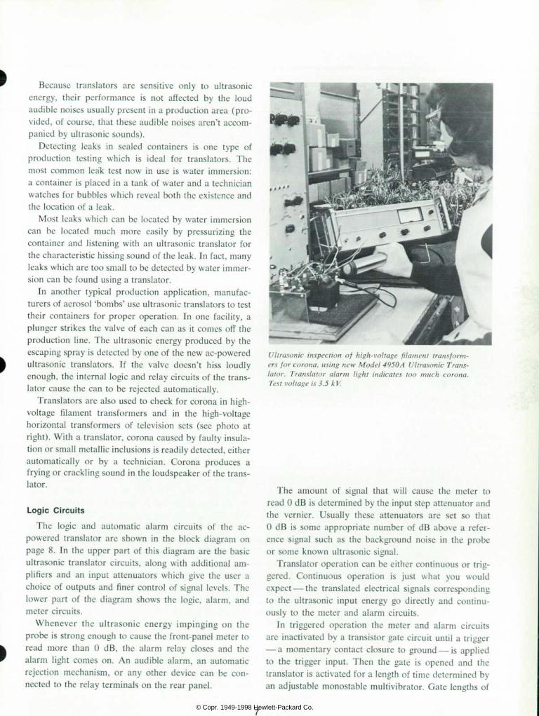
Translators are also used to check for corona in high- voltage filament transformers and in the high-voltage horizontal transformers of television sets (see photo at right). With a translator, corona caused by faulty insula tion or small metallic inclusions is readily detected, either automatically or by a technician. Corona produces a frying or crackling sound in the loudspeaker of the trans lator.
Logic Circui ts
The logic and automatic alarm circuits of the ac- powered translator are shown in the block diagram on page 8. In the upper part of this diagram are the basic ultrasonic translator circuits, along with additional am plifiers and an input attenuators which give the user a choice of outputs and finer control of signal levels. The lower part of the diagram shows the logic, alarm, and meter circuits.
Whenever the ultrasonic energy impinging on the probe is strong enough to cause the front-panel meter to read more than 0 dB, the alarm relay closes and the alarm light comes on. An audible alarm, an automatic rejection mechanism, or any other device can be con nected to the relay terminals on the rear panel.
Ultrasonic inspection of high-voltage filament transform
ers for corona, using new Model 4950 A Ultrasonic Trans
lator. Translator alarm light indicates too much corona.
Test voltage is 3.5 kV.
The amount of signal that will cause the meter to read 0 dB is determined by the input step attenuator and the vernier. Usually these attenuators are set so that 0 dB is some appropriate number of dB above a refer ence signal such as the background noise in the probe or some known ultrasonic signal.
Translator operation can be either continuous or trig gered. Continuous operation is just what you would expect — the translated electrical signals corresponding to the ultrasonic input energy go directly and continu ously to the meter and alarm circuits.
In triggered operation the meter and alarm circuits are inactivated by a transistor gate circuit until a trigger — a momentary contact closure to ground — is applied
to the trigger input. Then the gate is opened and the translator is activated for a length of time determined by an adjustable monostable multivibrator. Gate lengths of
© Copr. 1949-1998 Hewlett-Packard Co.
Osc i l loscope Output
Speaker
PROBE STEP ATTENUATOR - A M P M I X E R â € ” Â « - A M P
LOCAL OSCIL·LAT
4 0 k H z «
Inhibi t
Tr igger Input
^ 1 0 0 - m s _ DELAY LENGTH
CÃÃÃCLJÃT TRANSISTOR
SWITCH
MANUAL TRIGGER
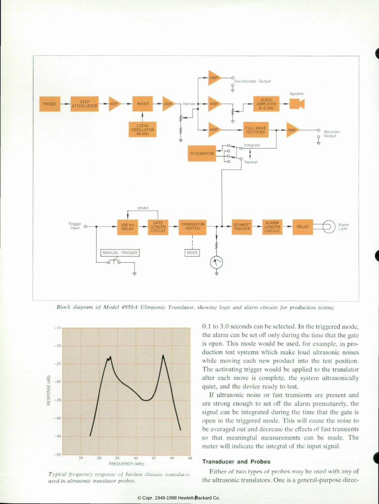
Block diagram of Model 4950A Ultrasonic Translator, showing logic and alarm circuits for production testing.
m B - 3 0
FREQUENCY (kHz)
Typical frequency response of barium titanatv
used in ultrasonic translator probes.
0.1 to 3.0 seconds can be selected. In the triggered mode, the alarm can be set off only during the time that the gate is open. This mode would be used, for example, in pro duction test systems which make loud ultrasonic noises while moving each new product into the test position. The activating trigger would be applied to the translator after each move is complete, the system ultrasonically quiet, and the device ready to test.
If ultrasonic noise or fast transients are present and are strong enough to set off the alarm prematurely, the signal can be integrated during the time that the gate is open in the triggered mode. This will cause the noise to be averaged out and decrease the effects of fast transients so that meaningful measurements can be made. The meter will indicate the integral of the input signal.
Transducer and Probes Either of two tvpes nf probes may be n«"H with any of
the ultrasonic translators. One is a general-purpose direc-
© Copr. 1949-1998 Hewlett-Packard Co.

tional microphone which is used to detect and locate sources which transmit their ultrasonic energy through the air. The second type of probe is a contact probe whose sensing end is a long, 1 1-cm, stainless-steel stylus. Heavy metallic structures such as engine blocks readily conduct ultrasonic energy, but are so massive that their surfaces do not vibrate enough to broadcast this energy through the air where it could be detected by the general- purpose probe. The contact probe is designed to be placed in contact with solid objects and to be sensitive to ultrasonic energy propagating in them. It is insensitive to sound waves in air.
Both probes use the same transducer element to con vert ultrasonic energy to electrical signals. The element is a thin rectangular piezoelectric crystal of barium titan- ate placed with its flat side perpendicular to the axis of the probe. This transducer element is one of the most sensitive types. Its frequency response has two peaks, typically at about 37 kHz and 43 kHz, as shown in the diagram on p. 8. As mentioned above, the defects of interest generate broad ultrasonic spectra, and all have significant energy in the 36-to-44-kHz range.
In the general-purpose probe the transducer element is preceded by a horn, or cone, which effects an efficient impedance match between airborne sound energy and stiff transducer, and contributes to directivity.
A small aluminum saddle at the end of the horn helps further to match the acoustical impedance of the air to the acoustical impedance of the barium titanate crystal. The horn, saddle, and crystal occupy about half the length of the general-purpose probe, and the other half of the probe contains a solid-state preamplifier.
In the contact probe, the transducer element is spring- mounted and placed in contact with a knife edge on the probe end of the stylus assembly. The contact probe also contains a solid-state preamplifier.
Robert L. Al len Th is i s Bob A l l en ' s second con t r i bu t i on t o t he Hew le t t -Packa rd Journa l i n as many months . Las t mon th he au thored an a r t i c le on the new Mode l 5260A 12 .4 GHz F requency D iv ide r , f o r wh ich he was p ro jec t l eade r wh i l e w i th t he - h p - F r e q u e n c y a n d T i m e D i v i s i o n . In th is month 's ar t ic le , he is s p e a k i n g i n h i s n e w c a p a c i t y o f e n g i n e e r i n g m a n a g e r o f t h e - h p - De lcon D iv i s i on .
Bob rece i ved h i s BS degree i n e lec t r i ca l eng inee r ing f rom Utah S ta te Un ivers i t y in 1960 . He worked the f o l l o w i n g s u m m e r f o r - h p - , t h e n r e t u r n e d t o U t a h S t a t e , g r a d u a t i n g i n 1 9 6 1 w i t h a n M S d e g r e e i n e l e c t r i c a l e n g i n e e r i n g . I n S e p t e m b e r , 1 9 6 1 , h e j o i n e d t h e F r e q u e n c y a n d T i m e D i v i s i o n f u l l - t i m e . H e c o n t r i b u t e d t o t h e d e s i g n o f t h e 5 2 7 5 A a n d 5 2 4 3 L C o u n t e r s a n d t h e 1 0 7 A Q u a r t z O s c i l l a t o r , a n d w a s p r o j e c t l e a d e r f o r d e v e l o p m e n t o f t h e 5 2 6 0 A F r e q u e n c y D i v i d e r a n d t h e 5240A D ig i ta l F requency Me te r . He has a pa ten t pend ing and has pub l i shed a pape r on the me thod o f f r equency d iv i s ion used in the 5260A and 5240A.
Bob i s a member o f IEEE, S igma X i , Ph i Kappa Ph i , and S i g m a T a u .
Acknowledgments Electrical design of the ac-powered ultrasonic trans
lator was initiated by Hans H. Junker. The final design was done by Donald W. Lolli. Ole Volhontseff did the mechanical design. Invaluable assistance was rendered by the -hp- Corporate Industrial Design Group. •
9 © Copr. 1949-1998 Hewlett-Packard Co.

S P E C I F I C A T I O N S
- f t p - Mode l 4950A
U l t rason ic T rans la to r
I N P U T : o f w i d e r a n g e p r o b e s w h i c h r e s p o n d t o u l t r a s o n i c n o i s e s i n t h e b a n d o f 3 6 - 4 4 k H z .
S I G N A L A T T E N U A T O R : S t e p : 1 0 d B / s t e p a t t e n u a t o r o v e r 9 0 d B r a n g e . F i n e : C o n t i n u o u s l y a d j u s t a b l e o v e r a r a n g e o f 2 0 d B .
G A T E M O D E S : C o n t i n u o u s : I n s t r u m e n t o p e r a t e s a s a n o r m a l u l t r a s o n i c d e t e c t o r . W h e n e v e r t h e s i g n a l e x c e e d s t h e t r i g g e r l e v e l , t h e r e l a y i s a c t u a t e d .
T R I G G E R : I n s t r u m e n t r e q u i r e s a t r i g g e r s i g n a l t o o p e n a g a t e i n t h e m e t e r c i r c u i t . T h e g a t e s t a y s o p e n f o r a p r e s e t g a t e t i m e a n d t h e n c l o s e s a u t o m a t i c a l l y . I f t h e u l t r a s o n i c s i g n a l e x c e e d s t h e t r i g g e r l e v e l w h i l e t h e g a t e i s o p e n , t h e r e l a y i s a c t u a t e d . T h e r e q u i r e d t r i g g e r s i g n a l i s a m o m e n t a r y c o n t a c t c l o s u r e .
G A T E s e c o n d s . L e n g t h o l g a t e c a n b e p r e s e t t o 0 . 1 , 0 . 3 , 1 . 0 , o r 3 . 0 s e c o n d s . ( T h i s a l s o s e t s t h e i n t e g r a t i n g t i m e i n t h e i n t e g r a t e m o d e . )
N O N - I N T E G R A T E : R e s p o n s e o f t h e i n s t r u m e n t i s d i r e c t l y p r o p o r t i o n a l t o t h e u l t r a s o n i c s i g n a l .
I N T E G R A T E : R e s p o n s e o f t h e i n s t r u m e n t i s p r o p o r t i o n a l t o t h e i n t e g r a l o f t h e u l t r a s o n i c s i g n a l .
A L A R M M O D E S : A l a r m l e n g t h : L e n g t h o f t i m e t h e r e l a y i s a c t u a t e d c a n b e p r e s e t t o 0 . 1 , 0 . 3 . 1 . 0 o r 3 . 0 s e c o n d s .
N O N * L A T C H : R e l a y i s a c t u a t e d w h e n e v e r t h e s i g n a l i s a b o v e t h e t r i g g e r l e v e l a n d d r o p s o u t w h e n t h e s i g n a l i s b e l o w t h e t r i g g e r l e v e l . H y s t e r e s i s i s a p p r o x i m a t e l y 2 d B .
L A T C H : b e l o w i s r e s e t b y p u s h i n g a l a r m l i g h t s w i t c h w h e n s i g n a l l e v e l d r o p s b e l o w t r i g g e r l e v e l .
A U D I O : H a s 2 w a t t a u d i o a m p l i f i e r , w i t h a b u i l t - i n l o u d s p e a k e r . A U X I L I A R Y O U T P U T S : O s c i l l o s c o p e : 1 . 0 V r m s o u t p u t f o r f u l l s c a l e m e t e r d e f l e c t i o n .
R e c o r d e r : 1 . 0 V d c o u t p u t f o r f u l l s c a l e m e t e r d e f l e c t i o n . P h o n e s : I n t e r n a l l o u d s p e a k e r i s d i s a b l e d w h e n e a r p h o n e s a r e c o n n e c t e d .
T E M P E R A T U R E : O p e r a t i n g t e m p e r a t u r e r a n g e O ' C t o 5 5 ' C . P H Y S I C A L C H A R A C T E R I S T I C S : D i m e n s i o n s : 1 6 y 4 " w i d e , S V Ã ¯ " h i g h . 1 1 ' / 4 " d e e p .
S y s t e m w e i g h t : 1 8 I b s ( 8 , 2 6 k g } . S h i p p i n g w e i g h t : 2 3 I b s ( 1 0 , 4 k g ) . P O W E R : 1 0 5 t o 1 2 5 o r 2 1 0 t o 2 5 0 v o l t s , 5 0 t o 6 0 H z . 1 5 w a t t s . P R I C E : 7 2 0 0 7 4 9 5 0 A , $ 1 4 7 5 , i n c l u d e s g e n e r a l - p u r p o s e p r o b e a n d c o r d . M o d e l 7 2 0 0 7
C o n t a c t P r o b e a v a i l a b l e a s o p t i o n a l a c c e s s o r y a t $ 1 5 0 a d d i t i o n a l .
M o d e l s 4 9 1 8 A a n d 1 1 8 P o r t a b l e U l t r a s o n i c T r a n s l a t o r s
C O N S T R U C T I O N : R u g g e d a l u m i n u m c h a s s i s a n d c a b i n e t w i t h d e t a c h a b l e f r o n t c o v e r w i t h o p e r a t i n g i n s t r u c t i o n s a n d a c c e s s o r y s t o r a g e . M i l - S p e c p r i n t e d c i r c u i t b o a r d ; o u t s i d e q u i c k - a c c e s s b a t t e r y c o m p a r t m e n t .
C I R C U I T R Y : B r o a d - r a n g e 4 . 5 v o l t t r a n s i s t o r i z e d c i r c u i t r y w i t h R F f i l t e r . H e r m e t i c a l l y s e a l e d p o w e r s w i t c h .
F R E Q U E N C Y R E S P O N S E : T r a n s l a t e s f r e q u e n c i e s b e t w e e n 3 6 a n d 4 4 k H z i n t o a u d i b l e s o u n d s ; o t h e r s o u n d s w i t h i n a u d i o r a n g e a r e s c r e e n e d o u t .
P R O B E A N D C O I L C O R D : H a n d - h e l d ; s h i e l d e d a g a i n s t R F i n t e r f e r e n c e : o u t p u t i m p e d a n c e 1 8 0 o h m s ; t r a n s i s t o r i z e d p r e - a m p l i f i e r ; c o n i c a l r e s p o n s e  ± 1 1  ° a t 3 d B p o i n t s . t h a n w i t h a s i x - f o o t c o i l c o r d e m p l o y i n g l a t c h - l o c k c o n n e c t o r s . L e s s t h a n 1 d B l o s s w h e n u s e d w i t h 1 0 0 - f o o t c o n n e c t i n g r a h l  « P r r > h  «  « i ? * - 1 3 4 " H i a m o m r v
6 1 / 4 " l o n g , i n c l u d i n g p r o t e c t i v e m o n e l - s c r e e n e d c a p . P o w e r t o p r o b e s u p p l i e d t h r o u g h c o r d f r o m m a i n u n i t .
M E T E R : g a s k e t e d s o u n d i n t e n s i t y m e a s u r e d b y o u t p u t m e t e r ; s e a l e d a n d g a s k e t e d t o l o c k c a l i b r a t i o n d i r t a n d c o n t a m i n a n t s ; s c a l e l e n g t h 1 . 7 5 i n c h e s ; l i n e a r c a l i b r a t i o n ( 0 - 1 0 0 ) o n u p p e r s c a l e f o r l o g g i n g r e l a t i v e m e a s u r e m e n t s ; l o w e r s c a l e c a l i b r a t e d f r o m
0 - 3 0 d B . S P E A K E R : I n c o r p o r a t e s 4 x 6 i n c h s p e a k e r ; n o r m a l p o w e r t o s p e a k e r 4 0 0 m W . T E M P E R A T U R E R A N G E : O s c i l l a t o r s t a b i l i t y  ± 1 5 H z . a n d s i g n a l t o n o i s e r a t i o w i t h i n
1 1 d B f r o m 0 C C t o 5 5 " C . H A Z A R D O U S L O C A T I O N S ( M o d e l 4 9 1 8 A o n l y ) : M e e t s r e q u i r e m e n t s o f U n d e r w r i t e r s '
L a b o r a t o r i e s , I n c . , f o r u s e i n H a z a r d o u s L o c a t i o n s C l a s s I . G r o u p D . L i s t e d u n d e r U L ' s R e - e x a m i n a t i o n S e r v i c e .
H E A D S E T J A C K : A u x i l i a r y 6 0 0 - o h m o u t p u t h e a d s e t j a c k . H e a d s e t f u r n i s h e d a s
s t a n d a r d . R E C O R D E R J A C K ( M o d e l 1 1 8 o n l y ) : 1 m A d c a v a i l a b l e . S I Z E : 1 1 " x 9 " x 8 % " . S Y S T E M W E I G H T : 1 1 I b s ; s h i p p i n g w e i g h t 1 4 I b s . B A T T E R Y I N F O R M A T I O N : 3 E v e r e a d y E - 4 2 o r e q u i v a l e n t ( m e r c u r y t y p e ) . B A T T E R Y L I F E : 5 0 0 - 7 0 0 h o u r s . P R I C E : M o d e l 4 9 1 8 A . S 8 5 0 . 0 0 , c o m p l e t e a n d i n c l u d i n g b a t t e r i e s , g e n e r a l - p u r p o s e
p r o b e , 7 2 0 0 7 6 - f o o t c o i l e d c o r d a n d p r o b e e x t e n s i o n a d a p t e r . M o d e l 7 2 0 0 7 C o n t a c t P r o b e a v a i l a b l e a s o p t i o n a l a c c e s s o r y a t $ 1 5 0 . 0 0 a d d i t i o n a l . M o d e l 1 1 8 ( s a m e a s M o d e l 4 9 1 8 A e x c e p t t h a t M o d e l 1 1 8 h a s r e c o r d e r o u t p u t a n d i s n o t U L - a p p r o v e d t o r u s e i n h a z a r d o u s l o c a t i o n s ) . $ 6 5 0 . 0 0 .
1 Model 4905A
Por tab le U l t rason ic Trans la to r
C O N S T R U C T I O N : R u g g e d a l u m i n u m c h a s s i s a n d c a s e ; s t a i n l e s s s t e e l h a r d w a r e t h r o u g h o u t ; M i l - S p e c p r i n t e d c i r c u i t b o a r d ; q u i c k - a c c e s s b a t t e r y c o m p a r t m e n t : d e t a c h a b l e c a b i n e t s i d e - p l a t e f o r s e r v i c i n g .
C I R C U I T R Y : B r o a d - r a n g e 4 . 5 V t r a n s i s t o r i z e d c i r c u i t r y w i t h R F f i l t e r p r o v i d e s 1 0 0 d B d y n a m i c r a n g e ; c i r c u i t g a i n c o n t r o l l e d b y a s i n g l e k n o b .
F R E Q U E N C Y R E S P O N S E : S a m e a s 4 9 1 8 A . P R O B E A N D C O I L C O R D : S a m e a s 4 9 1 8 A . M E T E R : S a m e a s 4 9 1 8 A . S P E A K E R : I n c o r p o r a t e s 2 . 5 i n c h s p e a k e r ; s e a l e d a g a i n s t m o i s t u r e ; n o m i n a l p o w e r t o
s p e a k e r 2 5 m W . T E M P E R A T U R E R A N G E : S a m e a s 4 9 1 8 A . H E A D S E T J A C K : A u x i l i a r y 6 0 0 - o h m o u t p u t h e a d s e t j a c k . S Y S T E M W E I G H T : N e t 6 I b s ( 2 , 7 k g ) ; s h i p p i n g w e i g h t 8 I b s ( 3 . 6 k g ) . B A T T E R Y I N F O R M A T I O N : T h r e e E v e r e a d y E - 1 2 o r e q u i v a l e n t ( m e r c u r y t y p e ) . B A T T E R Y L I F E : 3 6 0 - 5 0 0 h o u r s . D I M E N S I O N S : 8 1 4 " w i d e x 4 V S " h i g h x 2 V Â « " d e e p ( 2 0 . 9 x 1 1 . 4 x 5 . 7 1 c m ) . P R I C E : M o d e l 4 9 0 5 A . $ 5 9 5 . 0 0 .
M o d e l s 1 1 6 , 1 1 7 , 4 9 1 7 A P o r t a b l e U l t r a s o n i c T r a n s l a t o r s
( S p e c i f i c a t i o n s o n r e q u e s t )
M A N U F A C T U R I N G D I V I S I O N : - f t p - D e l c o n D i v i s i o n 3 3 3 L o g u e A v e n u e M o u n t a i n V i e  » . C a l i l o n i i a 3  « 1 4 0
10 © Copr. 1949-1998 Hewlett-Packard Co.

Fig. 1 . T/1 /.v new all solid state
-hp- Model 34 10 A AC Microvoltmeter
will measure signals even when
frequency and amplitude tire unknown.
A panel light helps in determining the proper setting of the range switch.
Adjusting the front panel Inning control
to within 1% of the signal frequency
eiuihlfs the phase-lock circuitry to
lock on and track the input signal
within the specified limits.
How to Recover Weak Signals Buried in Noise A n e w p h a s e - l o c k s y n c h r o n o u s d e t e c t o r e n a b l e s t h i s a c m i c rovo l tme te r t o l ock on t o s i gna l s obscu red by no i se .
By Raymond C. Hanson
MEASURING LOW-LEVEL SIGNALS nearly obscured by noise or other nonrelated signals is required in
many applications. Some general areas in which this condition is encountered include instrument calibration, communications and medical research.
The broadband, average responding voltmeter is lim ited in sensitivity by inherent noise and spurious signals. An extension of the average-responding voltmeter for very low level signals obscured by noise uses the syn chronous rectifier. When driven at the fundamental fre quency of a known waveform, the filtered output of a synchronous rectifier is proportional to the average value of that waveform. Noise and spurious signals are rejected.
Voltmeters using this technique require a clean, high- level reference signal input from the test signal source, or that the system under test use the local oscillator output of the voltmeter. In many cases such a hook-up is not convenient or is impossible.
A new ac microvoltmeter. Fig. 1, has been designed that uses a phase-lock oscillator to drive a synchronous rectifier, thus eliminating the need for a reference input.
It operates at any frequency from 5 Hz to 600 kHz and has a high input impedance of 10 megohms. Sensitivity is 3 microvolts full scale on the most sensitive range. Noise and spurious signals up to 20 dB above full scale are rejected.
Operat ion of the Microvoltmeter The circuit of the -hp- Model 3410A AC Microvolt-
meter, Fig. 2, consists of four major sections: The input or signal conditioning circuit, the phase lock loop, an inhibit circuit, and a meter circuit. When tuned to any discrete frequency between 5 Hz and 600 kHz, the meter indicates the rectified average value of the signal. All noise and nonharmonically related signals are filtered out.
Rejection of Submultiple Frequencies. The synchronous rectifier will respond to any odd harmonic of its drive frequency in inverse proportion to its harmonic number. Thus, if an input signal is at a frequency of 5000 Hz with a level of 5 mV, and the drive frequency is at 1000 Hz, the output dc of the synchronous rectifier will pro-
11 © Copr. 1949-1998 Hewlett-Packard Co.

Typical Applications of -hp- Model 3410A
Measuring Frequency of Signals in Noise A l o w - l e v e l s i g n a l i n t h e m i c r o v o l t r e g i o n c a n e a s i l y b e o b s c u r e d b y n o i s e ( a ) . D i r e c t r e a d i n g o f f r e q u e n c y w i t h a c o u n t e r i s n o t p o s s i b l e , e v e n w i t h a h i g h - g a i n p r e a m p l i f i e r . I n a d d i t i o n , a c o u n t e r m a y g i v e e r r o n e o u s r e a d i n g s i f t h e a m p l i t u d e s o f t h e m e a s u r e d s i g n a l s a r e f luc tua t ing .
T h e a c m i c r o v o l t m e t e r m a y b e u s e d a s a p r e a m p l i f i e r f o r a c o u n t e r . W h e n i t l o c k s t o a s i g n a l , i t s l o c a l o s c i l l a t o r o u t p u t ( a 5 V s q u a r e wave) (b ) . cons tan t amp l i t ude and a t t he i npu t s igna l f requency (b ) .
I t i s v e r y d i f f i c u l t t o s y n c h r o n i z e a n o s c i l l o s c o p e t o a l o w - l e v e l r e p e t i t i v e s i g n a l i n n o i s e . T h e a c m i c r o v o l t m e t e r c a n b e u s e d a s a sync sou rce by l ock i ng i t t o t he r epe t i t i ve s i gna l and app l y i ng i t s l o ca l osc i l l a t o r ou tpu t t o t he ex te rna l s ync t e rm ina l s o f t he osc i l l o scope ( c ) . T h u s o n i s p o s s i b l e t o s e e t h e r e p e t i t i v e n a t u r e o f t h e n o i s y s i g n a l o n the CRT.
Because the —hp— Model 341 OA is able to t rack a changing vol tage a n d m a i n t a i n v o l t a g e a c c u r a c y o v e r a r a n g e o f  ± 5 % o f t h e f r e q u e n c y r a n g e , i t i s p o s s i b l e t o m a k e m e a s u r e m e n t s w h e r e t h e f r e q u e n c y o f t h e i n p u t s i g n a l i s c h a n g i n g . T h e i n p u t f r e q u e n c y c a n c h a n g e a s f a s t a s 0 . 5 % p e r s e c o n d u p t o t h e 5 % f r e q u e n c y r a n g e .
COUNTER
SIGNAL SOURCE
hp- n 3 4 1 0 A ,
V e r t . O S C I L L O S C O P E E x t . S y n c . - o o -
(c)
Separating Closely Spaced Coherent Signals T w o s i g n a l s n o t r e l a t e d h a r m o n i c a l l y , b u t n e a r l y t h e s a m e a m p l i t u d e a n d f r e q u e n c y c a n b e m e a s u r e d i n d e p e n d e n t l y . I n t h i s a p p l i c a t i o n , t h e m i c r o v o l t m e t e r a t t h e l e f t i s t u n e d t o a 3 0 0 0 H z s i g n a l o f 7 0 m V . A t t h e l e v e l t h e m i c r o v o l t m e t e r i s r e a d i n g a 3 1 0 0 H z s i g n a l a t a l e v e l o f 9 0 m V . T h e s u m o f t h e t w o s i g n a l s ( E = V Ã ˆ 7 r + Ã ? = 1 1 4 m V ) i s d i s p l a y e d o n t h e t r u e R M S v o l t m e t e r a t t h e t o p . D i s p l a y e d o n t h e o s c i l l o s c o p e i s t h e c o m p o s i t e w a v e f o r m i l l u s t r a t i n g t h e 1 0 0 H z b e a t f requency .
Measuring Power Supply Ripple
R i p p l e o n a p o w e r s u p p l y o f u p t o a b o u t 1 5 0 V d c c a n b e m e a s u r e d w i th meas -hp - Mode l 341 OA M ic rovo l tme te r . The i ns t rumen t can meas u r e m i c r o v o l t s a t t h e u s u a l r i p p l e f r e q u e n c i e s o f 6 0 , 1 2 0 , 1 8 0 H z a n d others .
E v e r y s y s t e m h a s s o m e g r o u n d l o o p p r o b l e m a n d i t i s d i f f i c u l t o r i m p o s s i b l e t o p r e d i c t g r o u n d l o o p v o l t a g e . O n e m e t h o d o f d e t e r m i n i n g g r o u n d l o o p v o l t a g e i s s h o w n i n t h e b l o c k d i a g r a m ( a ) . B y d i s c o n n e c t i n g t h e i n p u t l e a d , b u t k e e p i n g t h e g r o u n d c o n n e c t i o n o n , t h e g r o u n d l o o p v o l t a g e m a y b e m e a s u r e d a s s h o w n . T h i s v o l t a g e i s s u b t r a c t e d f r om the r i pp le vo l t age read ing t o ob ta in t he t r ue r i pp le vo l t age .
R i p p l e o n t h e 1 V , 4 0 0 H z s o u r c e ( b ) i s o f t h e o r d e r o f 1 m V .
DC POWER SUPPLY
•hp- 3 4 1 0 A
(a )
12
© Copr. 1949-1998 Hewlett-Packard Co.
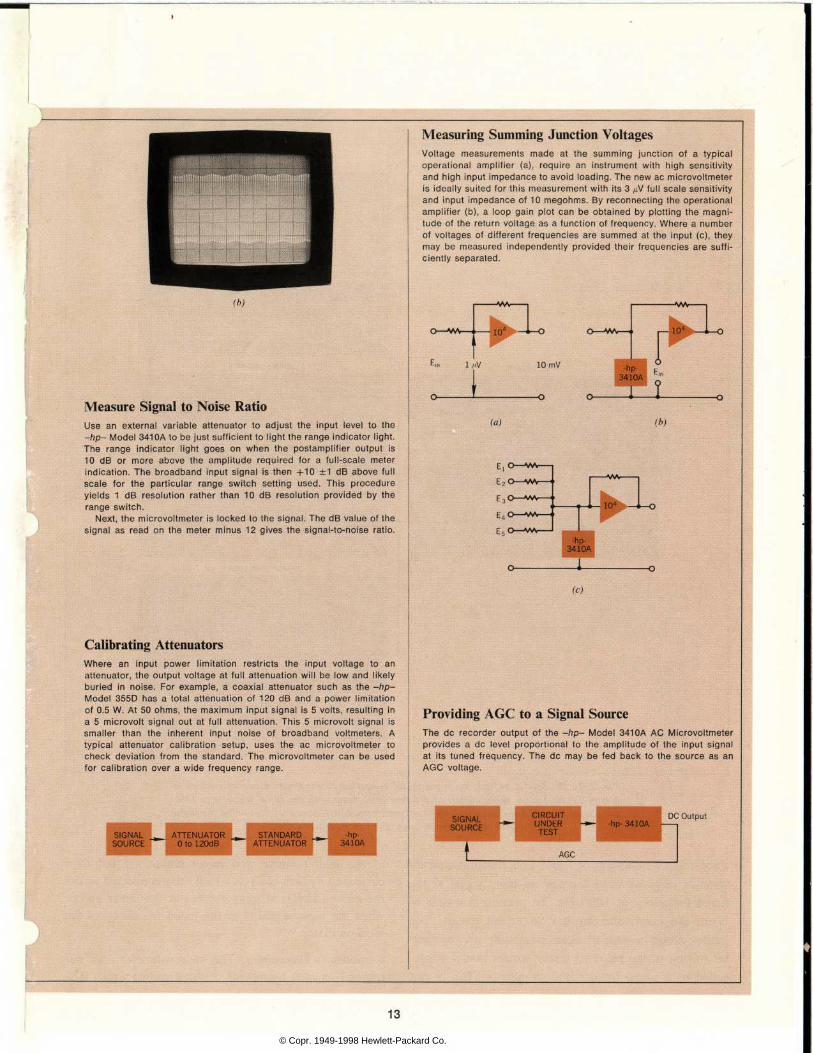
Measure Signal to Noise Ratio U s e a n e x t e r n a l v a r i a b l e a t t e n u a t o r t o a d j u s t t h e i n p u t l e v e l t o t h e —hp- Model 3410A to be jus t su f f ic ien t to l igh t the range ind ica tor l igh t . T h e r a n g e i n d i c a t o r l i g h t g o e s o n w h e n t h e p o s t a m p l i f i e r o u t p u t i s 1 0 d B o r m o r e a b o v e t h e a m p l i t u d e r e q u i r e d f o r a f u l l - s c a l e m e t e r i n d i c a t i o n . T h e b r o a d b a n d i n p u t s i g n a l i s t h e n + 1 0  ± 1 d B a b o v e f u l l s c a l e f o r t h e p a r t i c u l a r r a n g e s w i t c h s e t t i n g u s e d . T h i s p r o c e d u r e y i e l d s 1 d B r e s o l u t i o n r a t h e r t h a n 1 0 d B r e s o l u t i o n p r o v i d e d b y t h e range sw i t ch .
Nex t , the mic rovo l tmeter ¡s locked to the s igna l . The dB va lue o f the s i g n a l a s r e a d o n t h e m e t e r m i n u s 1 2 g i v e s t h e s i g n a l - t o - n o i s e r a t i o .
Calibrating Attenuators W h e r e a n i n p u t p o w e r l i m i t a t i o n r e s t r i c t s t h e i n p u t v o l t a g e t o a n a t t e n u a t o r , t h e o u t p u t v o l t a g e a t f u l l a t t e n u a t i o n w i l l b e l o w a n d l i k e l y b u r i e d i n n o i s e . F o r e x a m p l e , a c o a x i a l a t t e n u a t o r s u c h a s t h e - f t p - M o d e l 3 5 5 D h a s a t o t a l a t t e n u a t i o n o f 1 2 0 d B a n d a p o w e r l i m i t a t i o n o f 0 . 5 W. A t 50 ohms , t he max imum i npu t s i gna l i s 5 vo l t s , r esu l t i ng i n a 5 m i c r o v o l t s i g n a l o u t a t f u l l a t t e n u a t i o n . T h i s 5 m i c r o v o l t s i g n a l i s s m a l l e r t h a n t h e i n h e r e n t i n p u t n o i s e o f b r o a d b a n d v o l t m e t e r s . A t y p i c a l a t t e n u a t o r c a l i b r a t i o n s e t u p , u s e s t h e a c m i c r o v o l t m e t e r t o c h e c k d e v i a t i o n f r o m t h e s t a n d a r d . T h e m i c r o v o l t m e t e r c a n b e u s e d f o r c a l i b r a t i o n o v e r a w i d e f r e q u e n c y r a n g e .
SIGNAL SOURCE
A T T E N U A T O R 0 t o 1 2 0 d B
S T A N D A R D - h p - A T T E N U A T O R 3 4 1 0 A
Measuring Summing Junction Voltages V o l t a g e m e a s u r e m e n t s m a d e a t t h e s u m m i n g j u n c t i o n o f a t y p i c a l o p e r a t i o n a l a m p l i f i e r ( a ) , r e q u i r e a n i n s t r u m e n t w i t h h i g h s e n s i t i v i t y and h igh i npu t impedance t o avo id l oad ing . The new ac m ic rovo l tme te r is ideal ly sui ted for this measurement with i ts 3 ¿¿V ful l scale sensi t iv i ty a n d i n p u t i m p e d a n c e o f 1 0 m e g o h m s . B y r e c o n n e c t i n g t h e o p e r a t i o n a l a m p l i f i e r ( b ) , a l o o p g a i n p l o t c a n b e o b t a i n e d b y p l o t t i n g t h e m a g n i t u d e o f t h e r e t u r n v o l t a g e a s a f u n c t i o n o f f r e q u e n c y . W h e r e a n u m b e r o f v o l t a g e s o f d i f f e r e n t f r e q u e n c i e s a r e s u m m e d a t t h e i n p u t ( c ) , t h e y m a y b e m e a s u r e d i n d e p e n d e n t l y p r o v i d e d t h e i r f r e q u e n c i e s a r e s u f f i c ien t l y separa ted .
1/tV 10 mV
r -
- h p - E 3 4 1 0 A o '
_i L (a)
(c)
Providing AGC to a Signal Source T h e d c r e c o r d e r o u t p u t o f t h e - h p - M o d e l 3 4 1 0 A A C M i c r o v o l t m e t e r p r o v i d e s a d c l e v e l p r o p o r t i o n a l t o t h e a m p l i t u d e o f t h e i n p u t s i g n a l a t i t s a n f r e q u e n c y . T h e d c m a y b e f e d b a c k t o t h e s o u r c e a s a n A G C v o l t a g e .
SIGNAL SOURCE
CIRCUIT UNDER
TEST -hp- 341
DC Outpu t
AGC
13
© Copr. 1949-1998 Hewlett-Packard Co.

Fig. modulator is the Model 3410 A, the input signal is applied to the meter modulator which is driven Thus the square wave output of flip-flop 2 in phase with the input frequency. Thus the output from the meter modulator is a synchronous half-wave rectification of the input
signal which rejects even, but not odd harmonics.
duce a meter indication of 1 mV. This constitutes an er roneous response since there is no input signal at the
tuned frequency of 1000 Hz. To prevent this type of
error, the microvoltmeter has an inhibit circuit. The
inhibit circuit consists of signal processing circuits simi lar to that of the metering circuit except that it is pre ceded by a tuned frequency discriminator. The output
of the inhibit circuit and meter circuit are fed to a comparator which controls a reed relay connected across the meter. The reed relay shorts out the meter except when the input signal is at the tuned frequency of the local oscillator.
Response to Harmonics. The microvoltmeter does not respond to even harmonics of the signal to which it is
14 © Copr. 1949-1998 Hewlett-Packard Co.

Raymond C . Hanson Ray Hanson rece i ved h i s Bache lo r o f Sc i ence i n E l ec t r i ca l Eng inee r i ng f rom the Un ive rs i t y o f Ca l i f o rn ia in
B e r k e l e y i n 1 9 5 9 , a n d h i s M a s t e r o f I Sc ience in EE f rom New York
S m U n i v e r s i t y i n 1 9 6 1 . W h i l e a t t e n d i n g ^ â € ¢ ^ ^ B N Y U a n d a f t e r g r a d u a t i o n , h e w o r k e d
' a t B e l l L a b o r a t o r i e s o n v o i c e f t f ^ ^ f r e q u e n c y t e s t e q u i p m e n t ,
. ^ k U I R a y j o i n e d t h e H e w l e t t - P a c k a r d M ^ 1 I L o v e l a n d D i v i s i o n i n 1 9 6 3 a n d b e g a n
â € ¢ ^ ^ H i n v e s t i g a t i o n o f l o w - l e v e l d e t e c t i o n sys tems ou t o f wh ich grew the Mode l 341 OA AC Mic rovo l tmeter . He became pro jec t leader on the 341 OA.
locked. It responds to odd harmonics in proportion to their amplitude and phase relationship to the funda mental as do all average-responding voltmeters. If the instrument is tuned to a harmonic of some signal, it will respond to the odd multiples of that harmonic in propor tion to the amplitude and phase relationship of these odd multiples to the tuned harmonic.
Phase Lock Oscillator. The purpose of the phase-lock oscillator is to develop a drive signal for the synchronous rectifier. This drive signal must be in phase with the input signal, while the nature of the phase-lock oscillator is to lock at 90 degree phase with respect to the input signal. Therefore, to drive the synchronous rectifier, the phase-lock oscillator must produce two signals phase shifted by 90 degrees. This is accomplished by operating the voltage-controlled oscillator at four times the fre quency indicated on the frequency dial. The VCO pro vides a clock input for two flip-flops which are inter connected to divide by four and give two outputs with the proper 90 degree phase relationship.
The VCO is a free-running, multivibrator linearly tuned by means of voltage-controlled current sources. A low-pass filter in the phase-lock loop is changed each decade so that the frequency characteristic provides a capture range of 1 % at full-scale frequency and full-scale meter deflection. Lock range is defined here to be the frequency range over which the oscillator will track a drifting signal while maintaining a sufficiently small phase error to maintain rated accuracy in the microvoltmeter meter reading. The lock range is ±5%.
Range Indicator. Selective voltmeters may give erroneous readings due to spurious signals overloading the input. To avoid this problem, a range indicator light tells the
operator which range switch setting can be used with rated accuracy. It saves the operator time by indicating the range switch setting at which phase lock can be achieved, since the phase-lock loop has a finite dynamic range over which phase lock can be achieved. In the -hp- Model 3410A, this range is 20 dB above full-scale signal to — 20 dB below full scale. For larger signals, the active filter in the phase-lock loop does not operate linearly. For smaller signals, the capture range is reduced to the point where phase lock cannot be achieved.
The range indicator is a broadband detector which responds to the average value of the composite input sig nal. It lights the range indicator light when the signal level is about 10 dB above full scale. If the input is a "clean" signal and the range switch is stepped down until the light comes on, the signal level will be between 10 dB and 20 dB above full scale and phase lock can be ob tained. When phase lock is achieved by tuning, the meter will be pegged and it is necessary to up-range to obtain an on-scale indication. If spurious signals and/or noise exceeds the desired signal, then the meter indica tion may be less than full scale. If phase lock is not achieved, then the signal is too far below the noise to be recovered by the instrument.
Acknowledgment James L. Crooks was responsible for the product de
sign of the -hp- Model 3410A AC Microvoltmeter.
S P E C I F I C A T I O N S - f t p -
M o d e l 3 4 1 O A A C M i c r o v o l t m e t e r
V O L T A G E R A N G E : 3 j W f u l l s c a l e t o 3 V f u l l s c a l e ( - 1 1 0 d B m t o + 1 0 d B m ) . V O L T A G E A C C U R A C Y : ( % o ( f u l l s c a l e ) .
600kHz
g 5 0 k H z z
2 1 0 0 H z a E
25 Hz 10Hz
3 0 i ( V t o 3 V 1 0 0 V 3 , , V RANGE -Full Scale
F R E Q U E N C Y R A N G E : 5 H z t o 6 0 0 k H z i n d e c a d e r a n g e s . F R E Q U E N C Y D I A L A C C U R A C Y : Â ± 1 0 % ( u l l s c a l e ( u n l o c k e d ) . L i n e a r l y t u n e d o v e r e a c h
d e c a d e ( 5 d e c a d e s ) . P H A S E L O C K R A N G E : P u l l i n 1 Â ° l o f f u l l s c a l e f r e q u e n c y .
T r a c k â € ¢ 5 % o f f u l l s c a l e f r e q u e n c y . T r a c k i n g s p e e d V z % o f f u l l s c a l e / s .
M A X I M U M N O I S E R E J E C T I O N : 2 0 d B r m s a b o v e f u l l s c a l e o n a l l r a n g e s f o r r a t e d a c c u r a c y .
INPUT IMPEDANCE: 10 M ' . . ' shunted by 20 pF . M E T E R : v a l u e r m s v a l u e o f s i n e w a v e ; v o l t a g e i n d i c a t i o n p r o p o r t i o n a l t o a v e r a g e v a l u e
o f a p p l i e d w a v e . L i n e a r v o l t a g e s c a l e 0 t o 1 , 0 t o 3 ' d B s c a l e â € ” 1 2 t o + 2 d B ( 0 d B = m W i n t o 6 0 0 1 . ' ) .
L O C A L O S C I L L A T O R O U T P U T : 5 V s q u a r e w a v e . 1 0 0 0 ' . . ' o u t p u t i m p e d a n c e . R E C O R D E R O U T P U T : 1 m A i n t o 1 0 0 0 1 ! . 0 . 5 V a d j u s t a b l e o f f s e t l e v e l . AC POWER: 1 15 or 230 V • 10%. 50 to 1000 Hz. 22 W. P R I C E : - h p - M o d e l 3 4 1 0 A . $ 8 0 0 . 0 0 M A N U F A C T U R I N G D I V I S I O N : - h p - L o v e l a n d D i v i s i o n
P . O . B o x 3 0 1 L o v e l a n d . C o l o r a d o 8 0 5 3 7
15 © Copr. 1949-1998 Hewlett-Packard Co.

Using a Precision ac Amplif ier for Measurement and Cal ibrat ion Good ga in accuracy and low d is to r t ion in a genera l purpose ampl i f i e r make i t poss ib le to ex tend the range o f many ins t ruments .
By Rex James
PRECISION AC AMPLIFIERS, that is with stable, cali brated amplification characteristics, can extend the
useful range of many existing devices and instruments. A combination of accurate gain and low distortion makes a precision amplifier useful as a preamplifier in precision low-level ac measurements. Where the amplifier has a relatively high voltage output, it may be used as a post- amplifier for oscillators and function generators.
One such amplifier, the -hp- Model 463A Precision Amplifier, Fig. 1, has been designed to meet these re quirements. The desired characteristics were achieved by a combination of several features. Good gain accu racy and low distortion is dependent upon the differential input amplifier. Since this is the summing junction of the overall feed-back loop, Fig. 2, it is designed to have good common-mode rejection to assure stable gain accuracy and low distortion.
Distortion is generally introduced in the output ampli fier. A high-current capability with solid state devices with low distortion was accomplished using a push-pull
Fig. 1. Gain accuracies of better than ±0.001 dB of the -hp- Model 463 A Precision Amplifier make it useful for precision low-level signal measurements, calibration and many other
applications.
emitter-follower stage. The high voltage characteristics (100 V rms) were accomplished by stacking high voltage transistors so that they share the output voltage.
The forward gain of the open loop amplifier is main tained at 10.000 with a stability of approximately 1.0%. Then the feedback ratio is set with the precision feedback divider to set the closed loop gain of the amplifier. This feedback ratio can take on values of 0.1, 0.01, and 0.001 giving closed loop gains of 10, 100, and 1000. As the closed loop gain increases, the "loop gain" decreases. Therefore the gain accuracy, distortion, and other char acteristics are better on the X10 gain range. Of course, the feedback divider is the heart of the amplifier as far as determining the gain characteristics. For this reason, precision high frequency wire-wound resistors were used. Long-term stability of the feedback attenuator is shown in Fig. 3.
Low-Level Prec is ion Measurements Low distortion, high gain accuracy and high output
levels inherent in a precision amplifier make it possible to enhance the specifications of many existing instru ments. One of the most accurate ac voltage measuring devices is the indirectly heated thermocouple calibrated by the National Bureau of Standards. In this technique, the ac/dc transfer measurement (comparing the ac sig nal to be measured with a known dc signal) is a rather slow and tedious process even if an ac/dc transfer volt meter is used.
A problem associated with this method is the low input impedance of the thermocouple — about 200 ohms per volt. This low input impedance can cause errors because of loading. By using the -hp- Model 463 A as a preamplifier or buffer amplifier with the thermal transfer
16 © Copr. 1949-1998 Hewlett-Packard Co.
+ 2 1 0 - 2 1 0 + 2 1 0 - 2 1 0
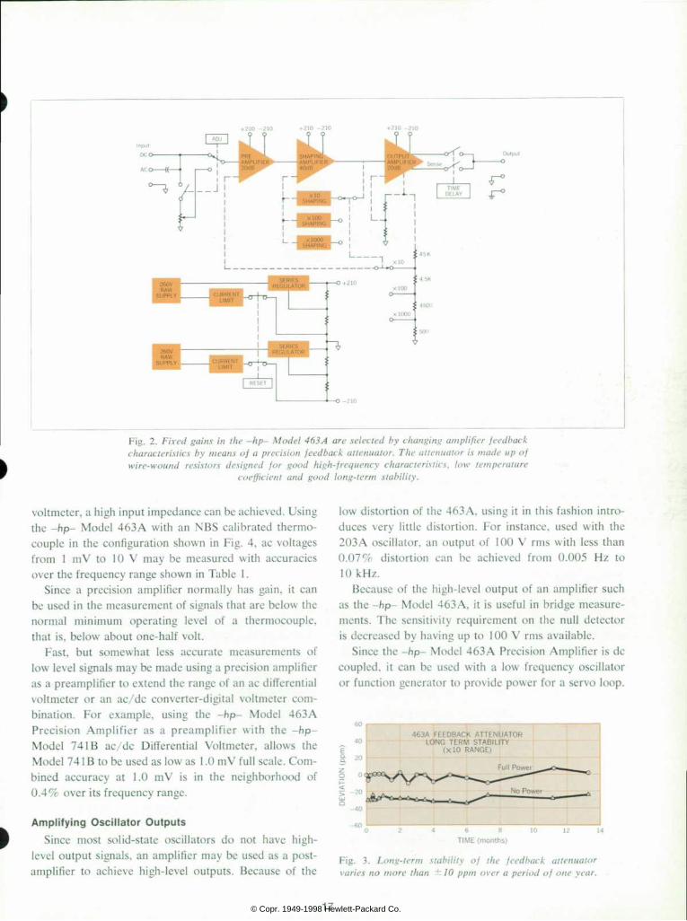
Fig. amplifier feedback gains in the -hp- Model 463 A arc selected by changing amplifier feedback
characteristics by means of a precision feedback attenuator. Tlte attenuator is made up of
wire-wound resistors designed for good high-frequency characteristics, low temperature
coefficient and good long-term stability.
voltmeter, a high input impedance can be achieved. Using the -hp- Model 463A with an NBS calibrated thermo couple in the configuration shown in Fig. 4, ac voltages from 1 mV to 10 V may be measured with accuracies over the frequency range shown in Table 1 .
Since a precision amplifier normally has gain, it can be used in the measurement of signals that are below the normal minimum operating level of a thermocouple, that is, below about one-half volt.
Fast, but somewhat less accurate measurements of low level signals may be made using a precision amplifier as a preamplifier to extend the range of an ac differential voltmeter or an ac/dc converter-digital voltmeter com bination. For example, using the -hp- Model 463A Precision Amplifier as a preamplifier with the -hp- Model 74 IB ac/dc Differential Voltmeter, allows the Model 74 1 B to be used as low as 1 .0 mV full scale. Com bined accuracy at 1.0 mV is in the neighborhood of 0.4% over its frequency range.
Ampli fy ing Osci l lator Outputs Since most solid-state oscillators do not have high-
level output signals, an amplifier may be used as a post- amplifier to achieve high-level outputs. Because of the
low distortion of the 463A, using it in this fashion intro duces very little distortion. For instance, used with the 203 A oscillator, an output of 100 V rms with less than 0.07% distortion can be achieved from 0.005 Hz to 10 kHz.
Because of the high-level output of an amplifier such as the -hp- Model 463A, it is useful in bridge measure ments. The sensitivity requirement on the null detector is decreased by having up to 100 V rms available.
Since the -hp- Model 463A Precision Amplifier is dc coupled, it can be used with a low frequency oscillator or function generator to provide power for a servo loop.
4 6 3 A F E E D B A C K A T T E N U A T O R L O N G T E R M S T A B I L I T Y
( X l O R A N G E )
T I M E ( m o n t h s )
Fig. 3 . Long- term s tabi l i ty o f the feedback at tenuator
varies no more than ± 10 ppm over a period of one year.
17 © Copr. 1949-1998 Hewlett-Packard Co.

O u t p u t s i n e w a v e t o b e m e a s u r e d
- h p - 4 6 3 A P R E C I S I O N A M P L I F I E R
- h p - 4 1 9 A M I C R O V O L T M E T E R
Fig. amplifier Measuring the output of an oscillator using a precision amplifier
as a buffer with an indirectly-heated thermocouple.
Its low frequency response makes it applicable for am plification of very low frequency signals such as in bio- medical experiments and geophysical measurements.
Cal ibra t ing Vol tmeters and At tenuators One method of generating accurate signals for calibra
tion is shown in Fig. 5. Output A is for low-level signals; output B is for high-level signals. If a 1 mV signal is needed at A, the gain of the amplifier should be set to 60 dB (xlOOO) and 1 V measured at the amplifier output. Since some measuring instruments are degraded in accuracy at very low levels, it is more desirable to accurately amplify the unknown and measure it at a higher level. Accuracy of the output at A is determined by the accuracy of the measuring instrument plus the accuracy of the amplifier. Noise generated in the ampli fier and any distortion introduced also affect accuracy.
Output B furnishes higher-level signals and is limited by the output capabilities of the amplifier. The gain accu racy of the amplifier is not a factor in the accuracy of this signal, but noise and distortion is a factor.
The instrument used to measure this calibration volt age may take a number of forms. The indirectly heated thermocouple previously mentioned as a low-level volt-
Table I Combined Accuracy of -hp- Model 463A
Precision Amplifier and an NBS Calibrated Thermocouple
age measuring device can be used. Another technique uses an ac differential voltmeter whose accuracy ap proaches that of the thermal transfer technique, and is much more convenient to use. The ac/dc converter used with a digital voltmeter is probably the most convenient method.
Accuracy Low-level signal measurements and precision calibra
tion voltages are limited in accuracy to the gain accuracy of the amplifier. Also, the noise and distortion of the amplifier can affect the measurement accuracy. For small signal to noise ratios «1/10), it can be shown that the percent error introduced into average reading and true rms reading instruments by Gaussian noise is:
% Error AVG ^ 25 ( Cm
% ErrorKMS = 50 ( —
Rex James R e x i s a g r a d u a t e o f B r i g h a m Y o u n g U n i v e r s i t y w i t h t h e d e g r e e o f B a c h e l o r o f E n g i n e e r i n g S c i e n c e s , a f i ve - yea r cou rse . He i s s t udy ing f o r h i s M S d e g r e e a t C o l o r a d o S t a t e U n i v e r s i t y . A f t e r g r a d u a t i o n f r o m B r i g h a m Y o u n g i n 1 9 6 3 , R e x j o i n e d t h e r e s e a r c h a n d d e v e l o p m e n t l abo ra to ry a t Love land . He worked on t h e - h p - M o d e l 7 4 1 A A C - D C D i f f e r e n t i a l V o l t m e t e r , t h e n h a d p r o j e c t r e s p o n s i b i l i t y f o r t h e - f t p -
M o d e l 4 6 3 A P r e c i s i o n A m p l i f i e r . H e i s p r e s e n t l y w o r k i n g o n d i g i t a l i n s t r u m e n t a t i o n . R e x i s a m e m b e r o f E t a K a p p a N u a n d T a u B e t a P i .
18 © Copr. 1949-1998 Hewlett-Packard Co.

S P E C I F I C A T I O N S - h p - M o d e l 4 6 3 A P r e c i s i o n A m p l i f i e r
F I X E D G A I N ( D C C o u p l e d ) x 1 0 R a n g e
A c c u r a c y : D C t o 1 0 H z , < _ L 0 . 0 3 % 1 0 H z t o 1 0 k H z , < Â ± 0 . 0 1 % 1 0 k H z t o 1 0 0 k H z . < Â ± 0 . 1 %
D C L i n e a r i t y : - 0 . 0 1 % D i s t o r t i o n ( 1 0 0 V O u t p u t , F u l l L o a d ) : 1 0 H z t o 1 0 k H z . < 0 . 0 1 %
1 0 k H z t o 1 0 0 k H z , < 0 . 1 % X 1 0 0 R a n g e
A c c u r a c y : D C t o 1 0 H z . < - 0 . 2 % 1 0 H z t o 2 0 k H z . < â € ¢ 0 . 1 % 2 0 k H z t o 1 0 0 k H z â € ¢ 1 O S
D C L i n e a r i t y : _ - . _ 0 . 0 3 % D i s t o r t i o n ( 1 0 0 V O u t p u t , F u l l L o a d ) : 1 0 H z t o 1 0 k H z , < 0 . 0 3 %
1 0 k H z t o 1 0 0 k H z , < 0 . 1 % X 1 0 0 0 R a n g e
A c c u r a c y : D C t o 1 0 H z , < Â ± 0 . 3 % 1 0 H z t o 2 0 k H z , < - 0 . 3 % 2 0 k H z t o 1 0 0 k H z . â € ¢ 3 . 0 Â ° 0
D C L i n e a r i t y : â € ¢ 0 . 1 % D i s t o r t i o n ( 1 0 0 V O u t p u t , F u l l L o a d ) : 1 0 H z t o 1 0 k H z , < 0 . 1 %
1 0 k H z t o 1 0 0 k H z , < 0 . 5 % F I X E D G A I N ( A C C o u p l e d )
I d e n t i c a l t o d c c o u p l e d e x c e p t c o u p l i n g c a p a c i t o r c a u s e s a 0 . 0 1 % e r r o r ( 2 5 H z ) t o a 3 - d B e r r o r ( 0 . 3 5 H z ) .
A D J U S T A B L E G A I N ( A C o r D C C o u p l e d ) G a i n m a y b e a d j u s t e d f r o m 0 t o 1 0 0 % o f t h e f i x e d g a i n r a n g e . D i s t o r t i o n a n d d c l i n e a r i t y c h a r a c t e r i s t i c s i d e n t i c a l w i t h f i x e d g a i n r a n g e .
I N P U T C H A R A C T E R I S T I C S I n p u t I m p e d a n c e :
F i x e d g a i n : 1 M L (  ± 5 % ) , < 3 5 p F A d j u s t a b l e g a i n : 5 0 k à à , < 2 0 0 p F
M a x i m u m I n p u t V o l t a g e : P r o t e c t e d t o  ± 1 5 0 v o l t s . A C c o u p l i n g c a p a c i t o r  ± 5 0 0 v o l t s p e a k .
-. â € ¢ e f e r r e d t o i n p u t ) :
G A I N R A N G E X 1 0 X 1 0 0 X 1 0 0 0
* W i t h i n p u t s h i e l d e d .
< 1 k S O U R C E
1 . 5 m V 150 f iV
50 /iV
1 . 5 m V 3 0 0 ^ V 2 0 0 / i V
O U T P U T C H A R A C T E R I S T I C S M a x i m u m O u t p u t : D C ; 1 1 0 v o l t s , 2 0 m A A C ; r e f e r t o c u r v e b e l o w
F R E Q U E N C Y L O A D C A P A B I L I T Y
M a x i m u m O u t p u t P o w e r : 5 w a t t s c o n t i n u o u s C u r r e n t L i m i t ( N o m i n a l ) : < 2 0 H z . 3 0 m A p e a k
> 2 0 H z . 9 0 m A p e a k M i n i m u m R e s i s t a n c e , A l l R a n g e s : 1 0 0 1 . ' M a x i m u m C a p a c i t a n c e : C a p a c i t a n c e d r i v e c a p a b i l i t y o f 4 6 3 A i n c r e a s e d b y a d d i r r e s i s t o r i n s e r i e s w i t h t h e o u t p u t a s i n d i c a t e d b e l o w .
O U T P U T I M P E D A N C E
P H A S E S H I F T ( F i j e d G a i n )
S Q U A R E W A V E R E S P O N S E ( F i x e d G a i n ) x 1 0 : 4 0 V p - p , 0 . 5 u s r i s e t i m e
x 1 0 0 : 6 0 V p - p , 1 L S r i s e t i m e x 1 0 0 0 : 2 0 0 V p - p . 2 / Â ¡ $ r i s e t i m e
M A N U F A C T U R I N G D I V I S I O N : - h p - L o v e l a n d D i v i s i o n P . O . B o x 3 0 1 L o v e l a n d , C o l o r a d o 8 0 5 3 7
How the -hp- Model 463A Amplifier is Calibrated
O n e o f t h e p r o b l e m s a s s o c i a t e d w i t h b u i l d i n g a n a m p l i f i e r w i t h t h e s p e c i f i c a t i o n s o f t h e 4 6 3 A i s c h e c k i n g t h e s p e c i f i c a t i o n s . T h r e e o f t h e h a r d e s t m e a s u r e m e n t s t o m a k e a r e t h e g a i n a c c u r a c y , t h e g a i n a c c u r a c y w i t h f r e q u e n c y o r f r e q u e n c y r e s p o n s e a n d t h e l o w d i s t o r t i o n m e a s u r e m e n t s . A m e t h o d u s e d t o c h e c k t h e b a s i c 1 k H z g a i n a c c u r a c y ( a l , u s e s a n a u t o t r a n s f o r m e r o f t h e i n d u c t i v e d i v i d e r t y p e o r d e c a d e t r a n s f o r m e r , a s t h e y a r e s o m e t i m e s c a l l e d . T h e d e c a d e t r a n s f o r m e r
(a)
j P & - * ^ *  ° : <±
O u t p u t
Decade T rans fe r n
5— -f u s e d h a s t e r m i n a l l i n e a r i t y s p e c i f i e d a t  ± ' / a p p m a t 1 k H z . B y a d j u s t i n g t h i s d e c a d e t r a n s f o r m e r f o r a n u l l r e a d i n g o n t h e n u l l i n d i c a t o r ( - h p - 4 0 3 A ) i n c o n j u n c t i o n w i t h t h e p h a s e s h i f t c o m p e n s a t o r s o f R 1 . C 1 o r R 2 , C 2 , t h e g a i n o f t h e a m p l i f i e r c a n b e r e a d a c c u r a t e l y f r o m t h e r a t i o i n d i c a t e d o n t h e d e c a d e t r a n s f o r m e r .
A m e t h o d u s e d t o c h e c k t h e f r e q u e n c y r e s p o n s e i s s h o w n a t ( b ) .
- h p - 7 4 I B A C / D C D I F F E R E N T I A L
V O L T M E T E R / D C S T A N D A R D
(b)
A s s u m i n g t h e a m p l i f i e r h a s b e e n c a l i b r a t e d f o r g o o d g a i n a c c u r a c y a t 1 k H z , t h e r e s i s t i v e d i v i d e r o f R 1 , R 2 a n d R 3 c a n b e a d j u s t e d s o t h a t t h e v o l t a g e r e a d a t p o i n t A a n d p o i n t B i s e x a c t l y t h e s a m e a t 1 k H z . T h i s i s r e a d t o 0 . 0 0 4 % r e s o l u t i o n o n a 7 4 1 B D i f f e r e n t i a l V o l t m e t e r . B y u s i n g m e t a l f i l m r e s i s t o r s f o r t h e r e s i s t i v e d i v i d e r a n d c a r e i n c o n s t r u c t i n g t h e d i v i d e r , i t s f r e q u e n c y r e s p o n s e c a n b e g u a r a n t e e d t o w i t h i n a p p r o x i m a t e l y 0 . 0 1 % a t 1 0 0 k H z . S i n c e t h e 7 4 1 B D i f f e r e n t i a l V o l t m e t e r i s c h e c k i n g t h e s a m e l e v e l a t p o i n t s A a n d B , i t s a c c u r a c y d o e s n o t e n t e r i n t o t h e m e a s u r e m e n t . I t s o n l y f u n c t i o n i s t o p r o v i d e t h e s e n s i t i v i t y a n d s t a b i l i t y n e c e s s a r y t o r e a d I n t h e a r e a o f 0 . 0 1 % e r r o r . T h e r e f o r e , a f t e r t h e r e s i s t i v e d i v i d e r h a s b e e n s e t a t 1 k H z . t h e o s c i l l a t o r c a n b e s w e p t o v e r t h e f r e q u e n c y r a n g e o f o p e r a t i o n a n d t h e e r r o r i n g a i n a t t h e s e v a r i o u s f r e q u e n c i e s c a n b e r e a d b y t h e d i f f e r e n c e i n t h e 741 B r ead ing a t po i n t s A and B .
F o r d i s t o r t i o n m e a s u r e m e n t s a t 1 k H z ( c ) , a g o o d l o w d i s t o r t i o n o s c i l l a t o r s u c h a s t h e - h p - M o d e l 2 0 0 C D c a n b e u s e d w i t h a l o w - p a s s o r b a n d - p a s s f i l t e r t o f i l t e r o u t t h e h a r m o n i c s g e n e r a t e d w i t h i n t h e o s c i l l a t o r . T h i s p r o d u c e s a l o w d i s t o r t i o n s i g n a l f o r t h e i n p u t o f t h e a m p l i -
(c)
f i e r . T o m e a s u r e t h e o u t p u t d i s t o r t i o n , t h e o u t p u t s i g n a l i s f e d f i r s t i n t o a 1 k H z n o t c h f i l t e r . B y u t i l i z i n g t h i s n o t c h f i l t e r t o r e j e c t t h e f u n d a m e n t a l s i g n a l , w e c a n i n c r e a s e t h e s e n s i t i v i t y o f t h e D i s t o r t i o n A n a l y z e r b e c a u s e o f t h e l e v e l o f t h e o u t p u t s i g n a l o f t h e a m p l i f i e r . T h i s m e t h o d a l l o w s m e a s u r e m e n t o f d i s t o r t i o n 8 5 d B d o w n b e l o w t h e f u n d a m e n t a l .
19 © Copr. 1949-1998 Hewlett-Packard Co.

«=s ^ ^ > .
I P L I T U D E S T A B L E L O W D I S T O R T I O N
O S C I L L A T O R O - !: P R E C I S I O N G A I N
A C A M P L I F I E R - O O -
O U T P U T A
P R E C I S I Ã “ M E A S U R I I
O D E V I C E
« N G
O U T P U T
Fig. 5. Generating precision liitili ami low level calibration
voltages. In the photo, a digital voltmeter is being used us
the precision measuring instrument.
where a is the rms value of the Gaussian noise and es is the rms value of the noiseless signal.
The percent error introduced by distortion in average reading and true rms instruments (where total harmonic distortion relative to fundamental is less than 1 %) can be shown to be:
100
where - is the ratio of the 3rd harmonic signal to the Si
fundamental signal, etc. For instance, if the following measurements were made with a wave analyzer:
the worst possible errors introduced would be:
%ErrorAVG= 100 f -°' 0 0 0 5 0 . 0 0 0 3 0 . 0 0 0 0 3
~ ~ C - I
+ ~(0.001 +0.0001 +0.00001)0
= 10o|o.000231 + -^-(0.00001)1
= 0.024%
% Errorln,s = '^ f(O.OOl)2 + (0.0005)^ + (0.0001)=
+ (0.0003)^ + (0.00001)- + (0.00003)0
= 0.000068%
As can be seen, there can be an appreciable error in troduced into an average reading instrument. Also, it should be noted that in the case of the average reading instruments that usually the even harmonic contribution will be negligible with respect to the odd harmonic con tribution.
Acknowledgments The mechanical and product design of the 463A was
led by Robert B. Moomaw with assistance by Billy E. Thayer. Front panel ideas were contributed by Roger L. Lee. Electrical design was by the undersigned under the helpful direction of William G. Smith and Donald F Schultz. •
HEWLETT-PACKARD JOURNAL̂ MAY we? volume is - Number 9
© Copr. 1949-1998 Hewlett-Packard Co.
![Lossless compression of digital audio - HP LabsLossless compression of digital audio - HP Labs ... y > ] > ...](https://static.fdocuments.net/doc/165x107/5e8ec5c8b729fb6de750814f/lossless-compression-of-digital-audio-hp-labs-lossless-compression-of-digital.jpg)


