1967 (Late) and 1968 CORVETTE TELESCOPING STEERING...
7
Last Revision: 03SE2012 1967 (Late) and 1968 CORVETTE TELESCOPING STEERING COLUMN DISASSEMBLY & REPAIR INSTRUCTIONS - PAPER #1 Disassembly and Repair Instructions Addressed in this Paper Difficulty Page REMOVE STRG WHEEL AND HORN PARTS Easy 2 REMOVE TURN SIGNAL LEVER Easy 2 REPLACE THE TURN SIGNAL SWITCH Moderate 3 & 4 REPLACE OR REPAIR UPPER COLUMN BEARING Moderate 6 ADJUST TELESCOPE LOCKING LEVER Easy 7 How the Paper is Setup This is the first of two papers that address various replacement and repair procedures that can be performed on 1967-1968 Corvette first generation, energy absorbing, telescoping (adjustable), steering columns. All of the service procedures outlined in this paper should be fairly easy and accomplished without removing the steering column from the car. The next paper (Disassembly & Repair Paper #2) addresses removing the steering column from the car and replacing the lower bearing (a somewhat more complex operation.) Right after start of production in 1967 the lower steering column bearings and steering shafts of both the telescoping (as well as standard non-adjustable) Corvette steering columns were revised. Since the 1967 Chevrolet Chassis Service Manual was already in print, it does not show or discuss any of the revised parts. Unfortunately, the 1968 manual was updated in a somewhat haphazard manner and is not entirely correct either. Since the early 1967 steering columns were few in number and parts are quite rare, I will not address the early steering shafts or lower bearings. 1967 and 1968 Steering Columns Even though the 1968 Corvette had an all new exterior and interior, the chassis remained the same as the 1967 model. For these reasons the 1967 Corvette telescoping steering column is similar but not identical to the 1968 Corvette column. The large mounting bracket (with three aluminum mounting capsules) is welded in place and is quite different between the two years. Also the 1968 steering column has a welded toe plate bracket on the lower end of the steering column. The 1967 column was clamped to a bracket that was part of the dash plate. Therefore, the columns will not interchange. It is not necessary to remove the steering column from the vehicle in order to work on the components in the upper end. Such things as the steering wheel, telescope lock, horn parts, turn signal switch, and the upper steering shaft bearing can all be removed and serviced in-car and are discussed in this D&R Paper #1. All part numbers in parenthesis ( ) refer to Strg Wheel & Horn Parts drawing on page 2. All part numbers beginning with # refer to Steering Column Blowup on page 4.
-
Upload
doankhuong -
Category
Documents
-
view
226 -
download
0
Transcript of 1967 (Late) and 1968 CORVETTE TELESCOPING STEERING...
Last Revision: 03SE2012
1967 (Late) and 1968 CORVETTE TELESCOPING STEERING
COLUMN DISASSEMBLY & REPAIR INSTRUCTIONS - PAPER #1
Disassembly and Repair Instructions Addressed in this Paper Difficulty Page
REMOVE STRG WHEEL AND HORN PARTS Easy 2
REMOVE TURN SIGNAL LEVER Easy 2
REPLACE THE TURN SIGNAL SWITCH Moderate 3 & 4
REPLACE OR REPAIR UPPER COLUMN BEARING Moderate 6
ADJUST TELESCOPE LOCKING LEVER Easy 7
How the Paper is Setup This is the first of two papers that address various replacement and repair procedures that
can be performed on 1967-1968 Corvette first generation, energy absorbing, telescoping
(adjustable), steering columns. All of the service procedures outlined in this paper should
be fairly easy and accomplished without removing the steering column from the car. The
next paper (Disassembly & Repair Paper #2) addresses removing the steering column
from the car and replacing the lower bearing (a somewhat more complex operation.)
Right after start of production in 1967 the lower steering column bearings and steering
shafts of both the telescoping (as well as standard non-adjustable) Corvette steering
columns were revised. Since the 1967 Chevrolet Chassis Service Manual was already in
print, it does not show or discuss any of the revised parts. Unfortunately, the 1968
manual was updated in a somewhat haphazard manner and is not entirely correct either.
Since the early 1967 steering columns were few in number and parts are quite rare, I will
not address the early steering shafts or lower bearings.
1967 and 1968 Steering Columns Even though the 1968 Corvette had an all new exterior and interior, the chassis remained
the same as the 1967 model. For these reasons the 1967 Corvette telescoping steering
column is similar but not identical to the 1968 Corvette column. The large mounting
bracket (with three aluminum mounting capsules) is welded in place and is quite different
between the two years. Also the 1968 steering column has a welded toe plate bracket on
the lower end of the steering column. The 1967 column was clamped to a bracket that
was part of the dash plate. Therefore, the columns will not interchange.
It is not necessary to remove the steering column from the vehicle in order to work on the
components in the upper end. Such things as the steering wheel, telescope lock, horn
parts, turn signal switch, and the upper steering shaft bearing can all be removed and
serviced in-car and are discussed in this D&R Paper #1.
All part numbers in parenthesis ( ) refer to Strg Wheel & Horn Parts drawing on page 2.
All part numbers beginning with # refer to Steering Column Blowup on page 4.
2
A Word of Caution Before Beginning Work On Your Steering Column DISCONNECT THE BATTERY.
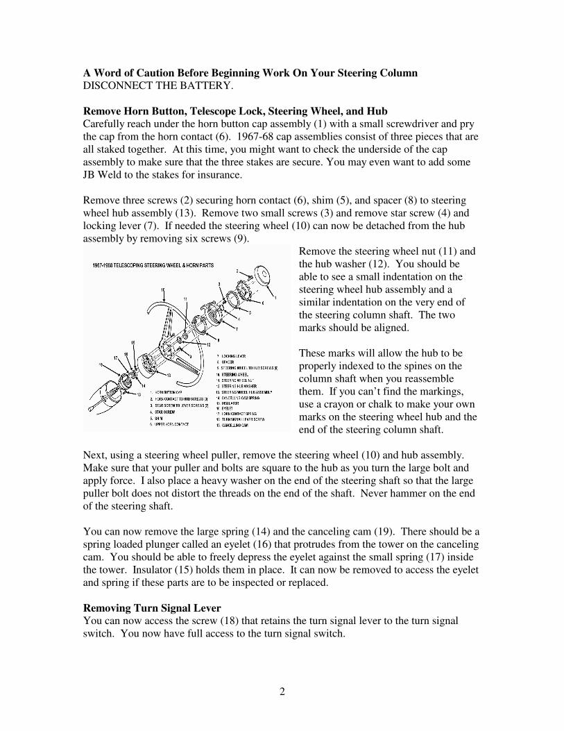
Remove Horn Button, Telescope Lock, Steering Wheel, and Hub Carefully reach under the horn button cap assembly (1) with a small screwdriver and pry
the cap from the horn contact (6). 1967-68 cap assemblies consist of three pieces that are
all staked together. At this time, you might want to check the underside of the cap
assembly to make sure that the three stakes are secure. You may even want to add some
JB Weld to the stakes for insurance.
Remove three screws (2) securing horn contact (6), shim (5), and spacer (8) to steering
wheel hub assembly (13). Remove two small screws (3) and remove star screw (4) and
locking lever (7). If needed the steering wheel (10) can now be detached from the hub
assembly by removing six screws (9).
Remove the steering wheel nut (11) and
the hub washer (12). You should be
able to see a small indentation on the
steering wheel hub assembly and a
similar indentation on the very end of
the steering column shaft. The two
marks should be aligned.
These marks will allow the hub to be
properly indexed to the spines on the
column shaft when you reassemble
them. If you can’t find the markings,
use a crayon or chalk to make your own
marks on the steering wheel hub and the
end of the steering column shaft.
Next, using a steering wheel puller, remove the steering wheel (10) and hub assembly.
Make sure that your puller and bolts are square to the hub as you turn the large bolt and
apply force. I also place a heavy washer on the end of the steering shaft so that the large
puller bolt does not distort the threads on the end of the shaft. Never hammer on the end
of the steering shaft.
You can now remove the large spring (14) and the canceling cam (19). There should be a
spring loaded plunger called an eyelet (16) that protrudes from the tower on the canceling
cam. You should be able to freely depress the eyelet against the small spring (17) inside
the tower. Insulator (15) holds them in place. It can now be removed to access the eyelet
and spring if these parts are to be inspected or replaced.
Removing Turn Signal Lever You can now access the screw (18) that retains the turn signal lever to the turn signal
switch. You now have full access to the turn signal switch.
3
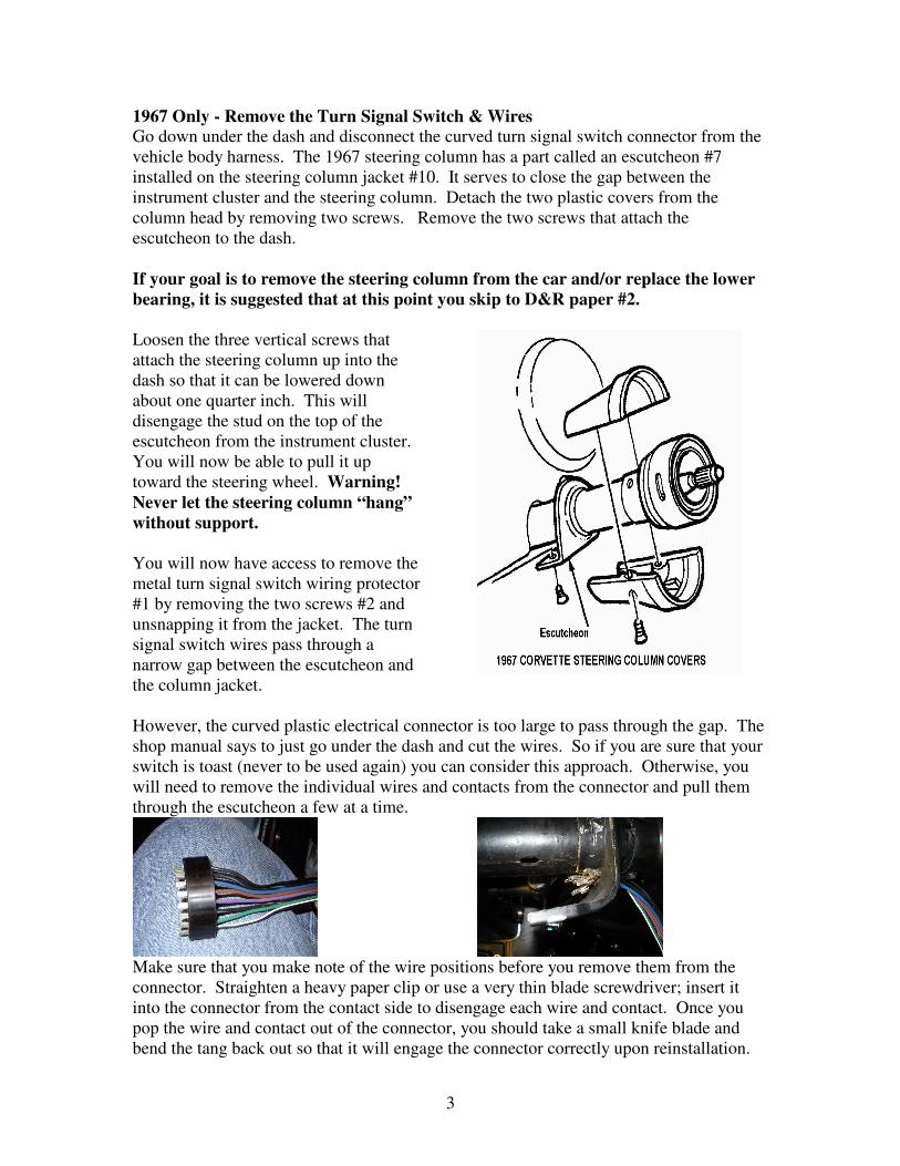
1967 Only - Remove the Turn Signal Switch & Wires Go down under the dash and disconnect the curved turn signal switch connector from the
vehicle body harness. The 1967 steering column has a part called an escutcheon #7
installed on the steering column jacket #10. It serves to close the gap between the
instrument cluster and the steering column. Detach the two plastic covers from the
column head by removing two screws. Remove the two screws that attach the
escutcheon to the dash.
If your goal is to remove the steering column from the car and/or replace the lower
bearing, it is suggested that at this point you skip to D&R paper #2.
Loosen the three vertical screws that
attach the steering column up into the
dash so that it can be lowered down
about one quarter inch. This will
disengage the stud on the top of the
escutcheon from the instrument cluster.
You will now be able to pull it up
toward the steering wheel. Warning!
Never let the steering column “hang”
without support.
You will now have access to remove the
metal turn signal switch wiring protector
#1 by removing the two screws #2 and
unsnapping it from the jacket. The turn
signal switch wires pass through a
narrow gap between the escutcheon and
the column jacket.
However, the curved plastic electrical connector is too large to pass through the gap. The
shop manual says to just go under the dash and cut the wires. So if you are sure that your
switch is toast (never to be used again) you can consider this approach. Otherwise, you
will need to remove the individual wires and contacts from the connector and pull them
through the escutcheon a few at a time.
Make sure that you make note of the wire positions before you remove them from the
connector. Straighten a heavy paper clip or use a very thin blade screwdriver; insert it
into the connector from the contact side to disengage each wire and contact. Once you
pop the wire and contact out of the connector, you should take a small knife blade and
bend the tang back out so that it will engage the connector correctly upon reinstallation.
4
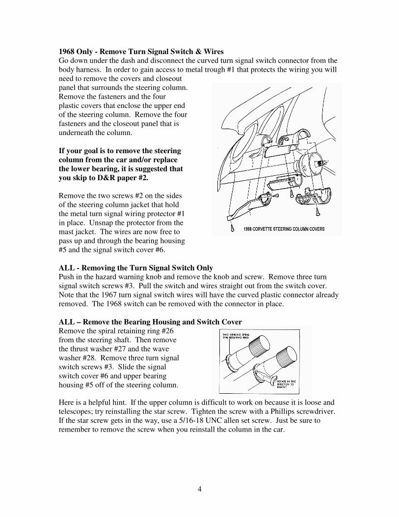
1968 Only - Remove Turn Signal Switch & Wires Go down under the dash and disconnect the curved turn signal switch connector from the
body harness. In order to gain access to metal trough #1 that protects the wiring you will
need to remove the covers and closeout
panel that surrounds the steering column.
Remove the fasteners and the four
plastic covers that enclose the upper end
of the steering column. Remove the four
fasteners and the closeout panel that is
underneath the column.
If your goal is to remove the steering
column from the car and/or replace
the lower bearing, it is suggested that
you skip to D&R paper #2.
Remove the two screws #2 on the sides
of the steering column jacket that hold
the metal turn signal wiring protector #1
in place. Unsnap the protector from the
mast jacket. The wires are now free to
pass up and through the bearing housing
#5 and the signal switch cover #6.
ALL - Removing the Turn Signal Switch Only Push in the hazard warning knob and remove the knob and screw. Remove three turn
signal switch screws #3. Pull the switch and wires straight out from the switch cover.
Note that the 1967 turn signal switch wires will have the curved plastic connector already
removed. The 1968 switch can be removed with the connector in place.
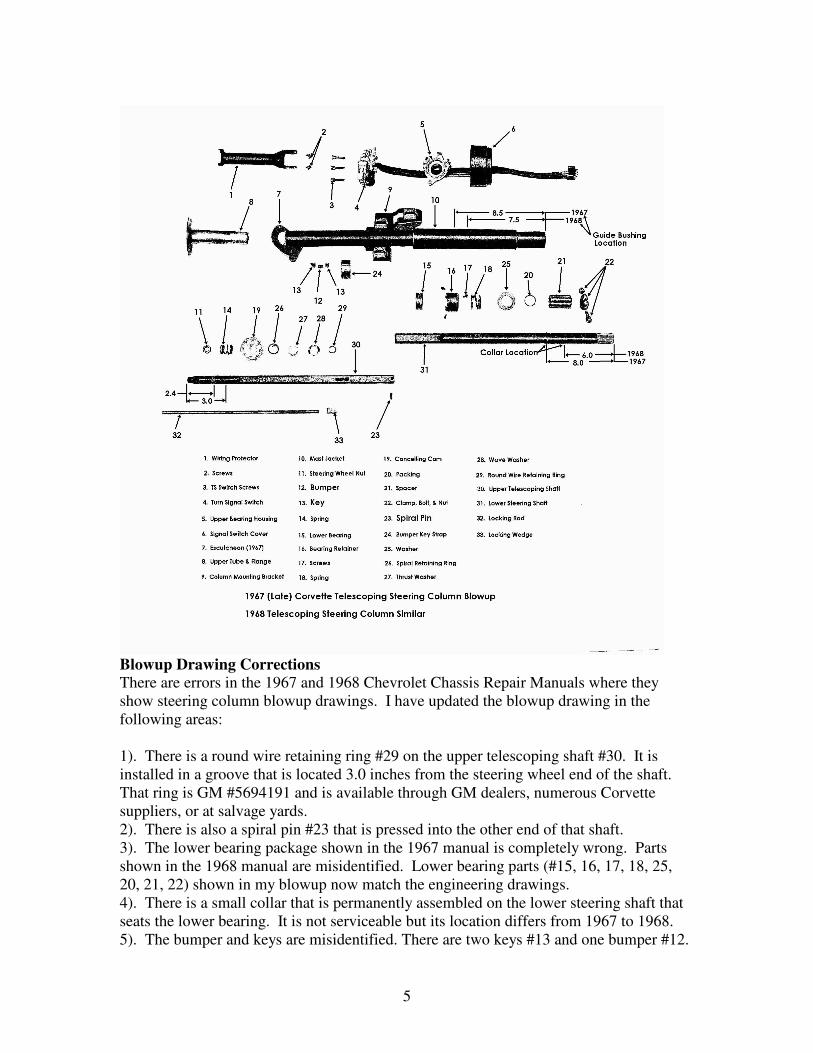
ALL – Remove the Bearing Housing and Switch Cover Remove the spiral retaining ring #26
from the steering shaft. Then remove
the thrust washer #27 and the wave
washer #28. Remove three turn signal
switch screws #3. Slide the signal
switch cover #6 and upper bearing
housing #5 off of the steering column.
Here is a helpful hint. If the upper column is difficult to work on because it is loose and
telescopes; try reinstalling the star screw. Tighten the screw with a Phillips screwdriver.
If the star screw gets in the way, use a 5/16-18 UNC allen set screw. Just be sure to
remember to remove the screw when you reinstall the column in the car.
5
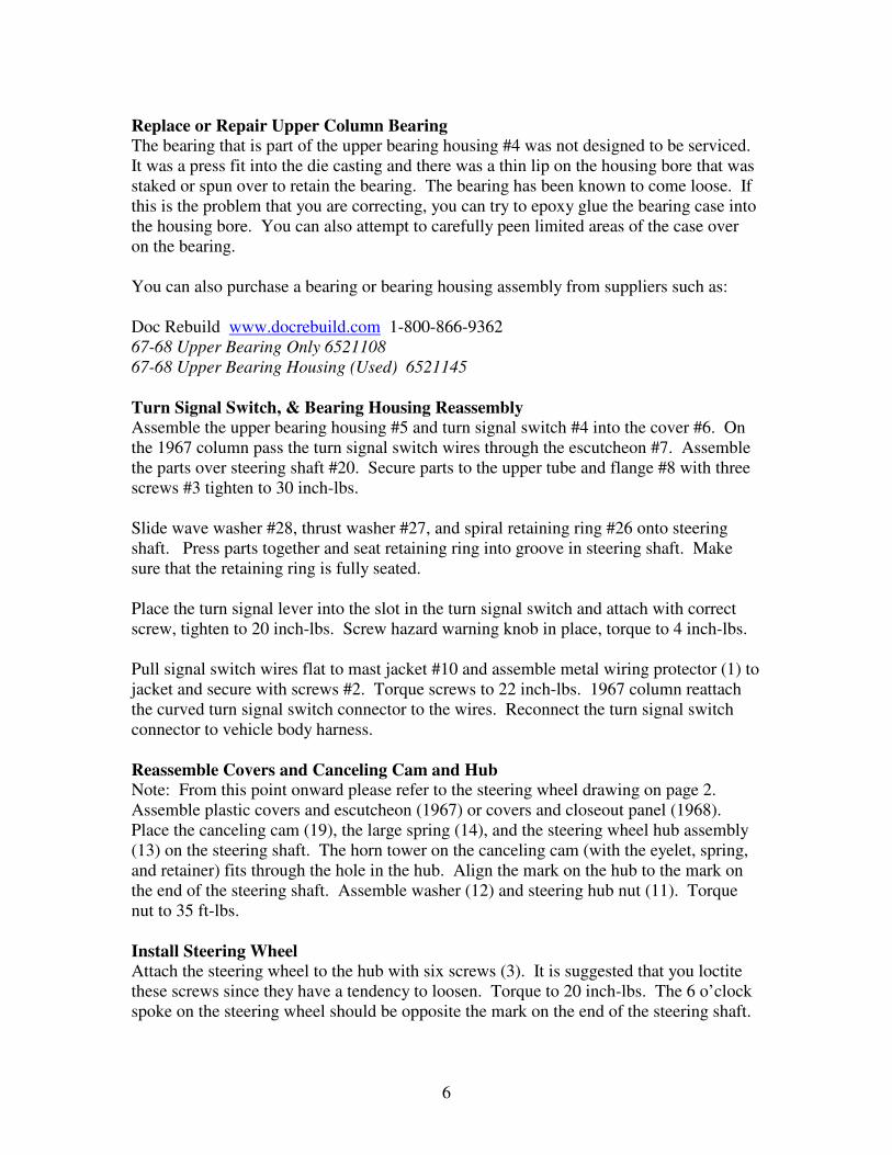
Blowup Drawing Corrections There are errors in the 1967 and 1968 Chevrolet Chassis Repair Manuals where they
show steering column blowup drawings. I have updated the blowup drawing in the
following areas:
1). There is a round wire retaining ring #29 on the upper telescoping shaft #30. It is
installed in a groove that is located 3.0 inches from the steering wheel end of the shaft.
That ring is GM #5694191 and is available through GM dealers, numerous Corvette
suppliers, or at salvage yards.
2). There is also a spiral pin #23 that is pressed into the other end of that shaft.
3). The lower bearing package shown in the 1967 manual is completely wrong. Parts
shown in the 1968 manual are misidentified. Lower bearing parts (#15, 16, 17, 18, 25,
20, 21, 22) shown in my blowup now match the engineering drawings.
4). There is a small collar that is permanently assembled on the lower steering shaft that
seats the lower bearing. It is not serviceable but its location differs from 1967 to 1968.
5). The bumper and keys are misidentified. There are two keys #13 and one bumper #12.
6
Replace or Repair Upper Column Bearing The bearing that is part of the upper bearing housing #4 was not designed to be serviced.
It was a press fit into the die casting and there was a thin lip on the housing bore that was
staked or spun over to retain the bearing. The bearing has been known to come loose. If
this is the problem that you are correcting, you can try to epoxy glue the bearing case into
the housing bore. You can also attempt to carefully peen limited areas of the case over
on the bearing.
You can also purchase a bearing or bearing housing assembly from suppliers such as:
Doc Rebuild www.docrebuild.com 1-800-866-9362
67-68 Upper Bearing Only 6521108
67-68 Upper Bearing Housing (Used) 6521145
Turn Signal Switch, & Bearing Housing Reassembly Assemble the upper bearing housing #5 and turn signal switch #4 into the cover #6. On
the 1967 column pass the turn signal switch wires through the escutcheon #7. Assemble
the parts over steering shaft #20. Secure parts to the upper tube and flange #8 with three
screws #3 tighten to 30 inch-lbs.
Slide wave washer #28, thrust washer #27, and spiral retaining ring #26 onto steering
shaft. Press parts together and seat retaining ring into groove in steering shaft. Make
sure that the retaining ring is fully seated.
Place the turn signal lever into the slot in the turn signal switch and attach with correct
screw, tighten to 20 inch-lbs. Screw hazard warning knob in place, torque to 4 inch-lbs.
Pull signal switch wires flat to mast jacket #10 and assemble metal wiring protector (1) to
jacket and secure with screws #2. Torque screws to 22 inch-lbs. 1967 column reattach
the curved turn signal switch connector to the wires. Reconnect the turn signal switch
connector to vehicle body harness.
Reassemble Covers and Canceling Cam and Hub Note: From this point onward please refer to the steering wheel drawing on page 2.
Assemble plastic covers and escutcheon (1967) or covers and closeout panel (1968).
Place the canceling cam (19), the large spring (14), and the steering wheel hub assembly
(13) on the steering shaft. The horn tower on the canceling cam (with the eyelet, spring,
and retainer) fits through the hole in the hub. Align the mark on the hub to the mark on
the end of the steering shaft. Assemble washer (12) and steering hub nut (11). Torque
nut to 35 ft-lbs.
Install Steering Wheel Attach the steering wheel to the hub with six screws (3). It is suggested that you loctite
these screws since they have a tendency to loosen. Torque to 20 inch-lbs. The 6 o’clock
spoke on the steering wheel should be opposite the mark on the end of the steering shaft.
7
Adjust Telescope Locking Lever Place the spacer (8) on the steering wheel hub assembly. Set the telescope locking lever
(7) on top of the spacer (with the steering wheel straight ahead, the finger tab part of the
lever should be in the 12 o’clock quadrant). Thread the special “star” screw (4) into the
end of the steering shaft. Now, use a phillips screwdriver to tighten the “star” screw until
you can no longer telescope the steering shaft. Place the finger part of the locking lever
at about the 1 o’clock position. Secure the locking lever to the “star” screw in that
position with the two small screws (3). Torque them to 30 inch-lbs. You can now test
the effort required to lock and unlock the telescope feature. Readjust the locking lever to
suit your preference.
Reassembly of Upper Horn Contacts Place the shim(s) (5) and the upper horn contact (6) on the spacer. Attach the horn
contact to the hub with three screws (2). Torque to 19 inch-lbs. Make sure that the eyelet
plunger (16) sticking up through the hub touches the horn contact.
Snap on the horn cap (1).
Reconnect the battery.
You are done!!!
Final Words of Caution: To maintain the energy absorbing function of the steering column, always replace screws,
bolts, and nuts with identical fasteners as specified.
If a steering column assembly is removed from the car, special care must be taken as you
handle it. A sharp blow on the end of the steering shaft, leaning on the column, or
dropping the column could shear the plastic fasteners inside the column which maintain
steering shaft and column rigidity. Remember, plastic parts that are over 25 years old can
be very brittle! Handle your steering column parts with care.
Never allow the steering column to just “hang” under the dash by only the floor pan
connections and the flexible coupling. This places very high stresses on the lower
column bearing and the mast jacket itself. Always have someone hold the column; block
it up; or wire it in place if you must remove the vertical bolts that hold it into the dash.
67-68TeleColumnD&R#1Rev03SE2012