1956 Ford F100 - Classic Instruments Home Ford F100 Installation Manual Revised September 13, 2013...
18
Revised September 13, 2013 CLASSIC INSTRUMENTS 1956 Ford F100 Installation Manual
Transcript of 1956 Ford F100 - Classic Instruments Home Ford F100 Installation Manual Revised September 13, 2013...

Revised September 13, 2013
CLASSIC INSTRUMENTS
1956 Ford F100
Installation Manual
Revised September 13, 2013
TABLE OF CONTENTS Welcome from the Team at Classic Instruments! ................................................. 3 Mount New Gauge Cluster .................................................................................... 4 Wiring Diagrams ................................................................................................... 5
SN16 or SN16F Speedometer Signal .............................................................................. 5 ECM / PCM Speedometer Signal ................................................................................... 6 Vehicle Speed Sensor Speedometer Signal .................................................................... 7
Wiring the Instrument Cluster ............................................................................... 8 Speedometer & Tachometer Wiring ............................................................................... 8 Circuit Board Connector Wiring ..................................................................................... 9
Fuel Level Sender Installation ............................................................................. 11 Calibrate the Speedometer & Tachometer .......................................................... 14
Entering Setup Mode: ................................................................................................... 14 Tachometer Setup: ........................................................................................................ 15
Cylinder Select: ......................................................................................................... 15 Tachometer Signal Type: .......................................................................................... 15
Speedometer Setup: ...................................................................................................... 16 Speed Auto Calibrate: ............................................................................................... 17 Real-Time Speed Adjust: .......................................................................................... 17

Revised September 13, 2013
Welcome from the Team at Classic Instruments! Our congratulations and appreciation for your purchase of one of the finest quality sets of
specialty instruments ever produced! Your instrument set has been conceived, designed, and manufactured by Classic Instruments, Inc. in the U.S.A. Each instrument has been tested and certified for accuracy and quality before packaging and shipping.
For trouble-free installation and operation follow the instructions exactly as outlined. Your instruments were assembled to precise specifications and although each has a five (5) year warranty covering defective parts and workmanship – this warranty will not cover instruments or sender units which have been installed incorrectly.
Follow our recommended procedures for installation and proper hookup to maintain the value and appearance of your instrument set during many future years of accurate and dependable service!
LIMITED WARRANTY
Classic Instruments, Inc. (CI) warrants to the original purchaser that any CI product manufactured or supplied by CI will be free from defects in material and workmanship under normal use and service for a period of five (5) years from date of purchase.
Improper installation, use of sending units other than CI’s or attempted repair or adjustments by other than CI shall void this warranty. Disassembly of any instruments or senders for whatever reason shall specifically void this warranty.
It’s always easy to look to a part for an issue with your set. Before you conclude that a part may be bad, thoroughly check your work. Today’s semiconductors and passive components have reached incredibly high reliability levels, but there is still room for error in our human construction skills. However, on rare occasions a sour part can slip through. Please be aware that testing can usually determine if the part was truly defective or damaged by assembly or usage. Don’t be afraid of telling us that you “blew it”, we’re all human and in most cases, replacement parts are very reasonably priced.
Purchaser requesting a product to be repaired or replaced under warranty must first call CI at 1-800-575-0461 before the return of defective part. Send defective part either to 826 Moll Drive, through UPS, or to P.O. Box 411 through U.S. Mail, Boyne City, MI 49712, USA. Include a written description of the failure with defective part.
Purchaser agrees and accepts that under no circumstances will a warranty replacement be furnished until CI has first received, inspected, and tested the returned part.
All other warranties expressed or implied are hereby excluded including any implied warranty of merchandise and implied warranty of fitness for a particular purpose. The sole and exclusive remedy for breach of this warranty is limited to the replacement set forth above.
It is expressly agreed that there shall be no further remedy for consequential or other type of damage, including any claim for loss of profit, engine damage or injury.
TECHNICAL ASSISTANCE 1-800-575-0461
OR Visit our website for the latest in gauge design and updates to our installation manual
www.classicinstruments.com
Revised September 13, 2013
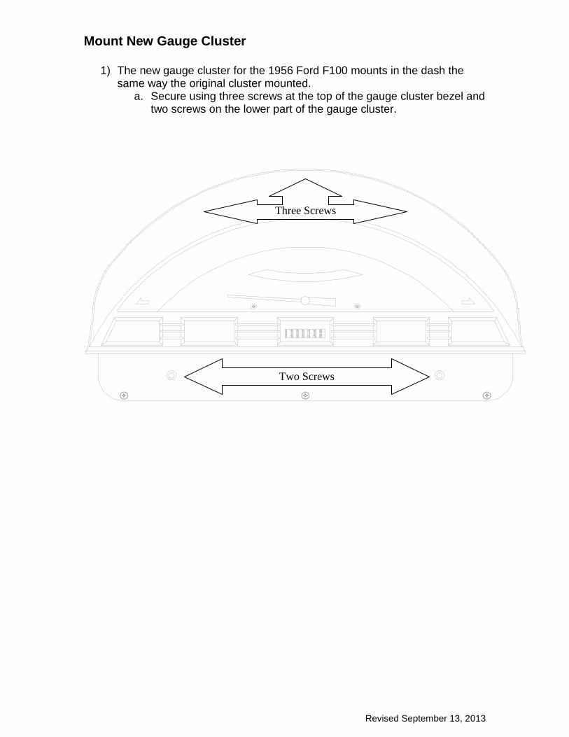
Mount New Gauge Cluster
1) The new gauge cluster for the 1956 Ford F100 mounts in the dash the same way the original cluster mounted.
a. Secure using three screws at the top of the gauge cluster bezel and two screws on the lower part of the gauge cluster.
Two Screws
Three Screws

Revised September 13, 2013
Wiring Diagrams
SN16 or SN16F Speedometer Signal
Good C
hassis Ground [B
lack]
+12VDC
Switched [Pink]
Pulse Signal Generator Pow
er [Red]
(use only with SN
16 or SN16F
)
Red
Black
White
Speedometer Signal Input [Purple]
SN16
Function Button Input [Brow
n]
Good C
hassis Ground
Pushbutton
Tachometer Signal [W
hite]
+12VDC
switched [9]
Good C
hassis Ground [8]
Fuel Level Signal [7]
Oil Pressure Signal [6]
Water Tem
perature Signal [5]
Left Turn Indicator [4]
Right Turn Indicator [3]
High Beam
Indicator [2]
Dash Light Pow
er [1]
12
34
56
78
9
Grey, B
lue / White,
Purple / White
and Green / W
hitew
ires are NO
T used.
Dash Light D
imm
er
Ground
Speedo / Tach Harness
Circuit Board
Connector Plug

Revised September 13, 2013
ECM / PCM Speedometer Signal
+12VD
C sw
itched [9]
Good C
hassis Ground [8]
Fuel Level Signal [7]
Oil P
ressure Signal [6]
Water Tem
perature Signal [5]
Left Turn Indicator [4]
Right Turn Indicator [3]
High B
eam Indicator [2]
Dash Light Pow
er [1]
12
34
56
78
9
Good C
hassis Ground [B
lack]
Function Button Input [B
rown]
Good C
hassis Ground
Pushbutton
Tachometer Signal [W
hite]
Pulse S
ignal Generator Pow
er [Red]
(use only with S
N16 or S
N16F
)
Speedom
eter Signal Input [Purple]
Not U
sedEC
M (C
omputer)
Speed Signal
Dash Light D
imm
er
Grey, B
lue / White,
Purple / White
and Green / W
hitew
ires are NO
T used.
Speedo / Tach H
arness
Circuit B
oardC
onnector Plug
Revised September 13, 2013
Vehicle Speed Sensor Speedometer Signal
Speedom
eter Signal Input [Purple]
Transmission
Ground
(same place as black w
ire)
Good C
hassis Ground [B
lack]
Function Button Input [B
rown]
Good C
hassis Ground
Pushbutton
Tachometer S
ignal [White]
Pulse S
ignal Generator P
ower [R
ed](use only w
ith SN
16 or SN
16F)
Not U
sed
+12VD
C sw
itched [9]
Good C
hassis Ground [8]
Fuel Level Signal [7]
Oil P
ressure Signal [6]
Water Tem
perature Signal [5]
Left Turn Indicator [4]
Right Turn Indicator [3]
High B
eam Indicator [2]
Dash Light P
ower [1]
12
34
56
78
9
Dash Light D
imm
er
Grey, B
lue / White,
Purple / White
and Green / W
hitew
ires are NO
T used.
Speedo / Tach H
arness
Circuit B
oardC
onnector Plug
Revised September 13, 2013
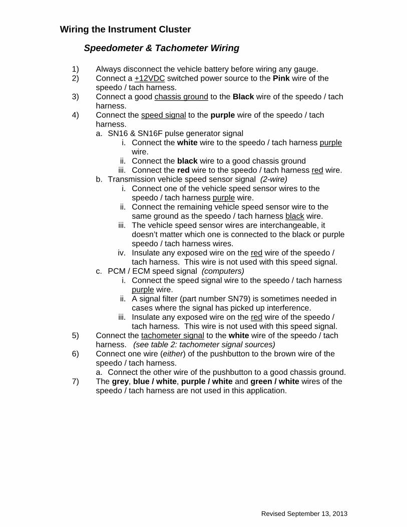
Wiring the Instrument Cluster
Speedometer & Tachometer Wiring
1) Always disconnect the vehicle battery before wiring any gauge. 2) Connect a +12VDC switched power source to the Pink wire of the
speedo / tach harness. 3) Connect a good chassis ground to the Black wire of the speedo / tach
harness. 4) Connect the speed signal to the purple wire of the speedo / tach
harness. a. SN16 & SN16F pulse generator signal
i. Connect the white wire to the speedo / tach harness purple wire.
ii. Connect the black wire to a good chassis ground iii. Connect the red wire to the speedo / tach harness red wire.
b. Transmission vehicle speed sensor signal (2-wire) i. Connect one of the vehicle speed sensor wires to the
speedo / tach harness purple wire. ii. Connect the remaining vehicle speed sensor wire to the
same ground as the speedo / tach harness black wire. iii. The vehicle speed sensor wires are interchangeable, it
doesn’t matter which one is connected to the black or purple speedo / tach harness wires.
iv. Insulate any exposed wire on the red wire of the speedo / tach harness. This wire is not used with this speed signal.
c. PCM / ECM speed signal (computers) i. Connect the speed signal wire to the speedo / tach harness
purple wire. ii. A signal filter (part number SN79) is sometimes needed in
cases where the signal has picked up interference. iii. Insulate any exposed wire on the red wire of the speedo /
tach harness. This wire is not used with this speed signal. 5) Connect the tachometer signal to the white wire of the speedo / tach
harness. (see table 2: tachometer signal sources) 6) Connect one wire (either) of the pushbutton to the brown wire of the
speedo / tach harness. a. Connect the other wire of the pushbutton to a good chassis ground.
7) The grey, blue / white, purple / white and green / white wires of the speedo / tach harness are not used in this application.
Revised September 13, 2013
Table 2: Tachometer Signal Sources
Circuit Board Connector Wiring
1) Always disconnect the vehicle battery before wiring any gauge. 2) Connect dash light power to position 1 of the circuit board connector
plug. 3) Connect the high beam indicator power to position 2 of the circuit
board connector plug. 4) Connect the right turn indicator power from the vehicle’s turn signal
switch to position 3 of the circuit board connector plug. 5) Connect the left turn indicator power from the vehicle’s turn signal
switch to position 4 of the circuit board connector plug. 6) Connect the water temperature signal wire to position 5 of the circuit
board connector plug. (see figure 2) 7) Connect the oil pressure signal wire to position 6 of the circuit board
connector plug. (see figure 1) 8) Connect the fuel level signal wire to position 7 of the circuit board
connector plug. 9) Connect a good chassis ground to position 8 of the circuit board
connector plug. 10) Connect a good +12VDC switched power source to position 9 of the
circuit board connector plug.
Ignition System Tachometer Signal Source Standard Points & Condenser
System Negative side of coil (usually marked “-“)
GM – HEI (High Energy Ignition) System
Terminal marked “TACH” on coil side of distributor cap.
MSD (Multiple Spark Discharge) System
TACH post on MSD box. If there isn’t a box, signal comes from negative side of
coil. If tachometer doesn’t respond correctly, your MSD system may require a MSD TACH adapter part #8910 or #8920. Contact MSD for the correct adapter for
your application.
Vertex Magneto System
“KILL” terminal on side of Vertex magneto body. An external adapter such as a MSD
Pro Mag Tach Converter #8132 may be required.
Mallory Ignition System
Negative side of coil (usually marked “-“) Important! Some Mallory ignition systems require the tachometer to be set at the 4-
cylinder setting.
ECM (computer) Tachometer Signal
Signal comes from the computer. You may need to set the tachometer to the
4-cylinder setting. The tachometer should also be set for 5V signals.
All Other Ignition Systems Please look at the owner’s manual for the location of the tachometer signal.
Revised September 13, 2013
Nut
Lock Washer
Washer
Signal Wire
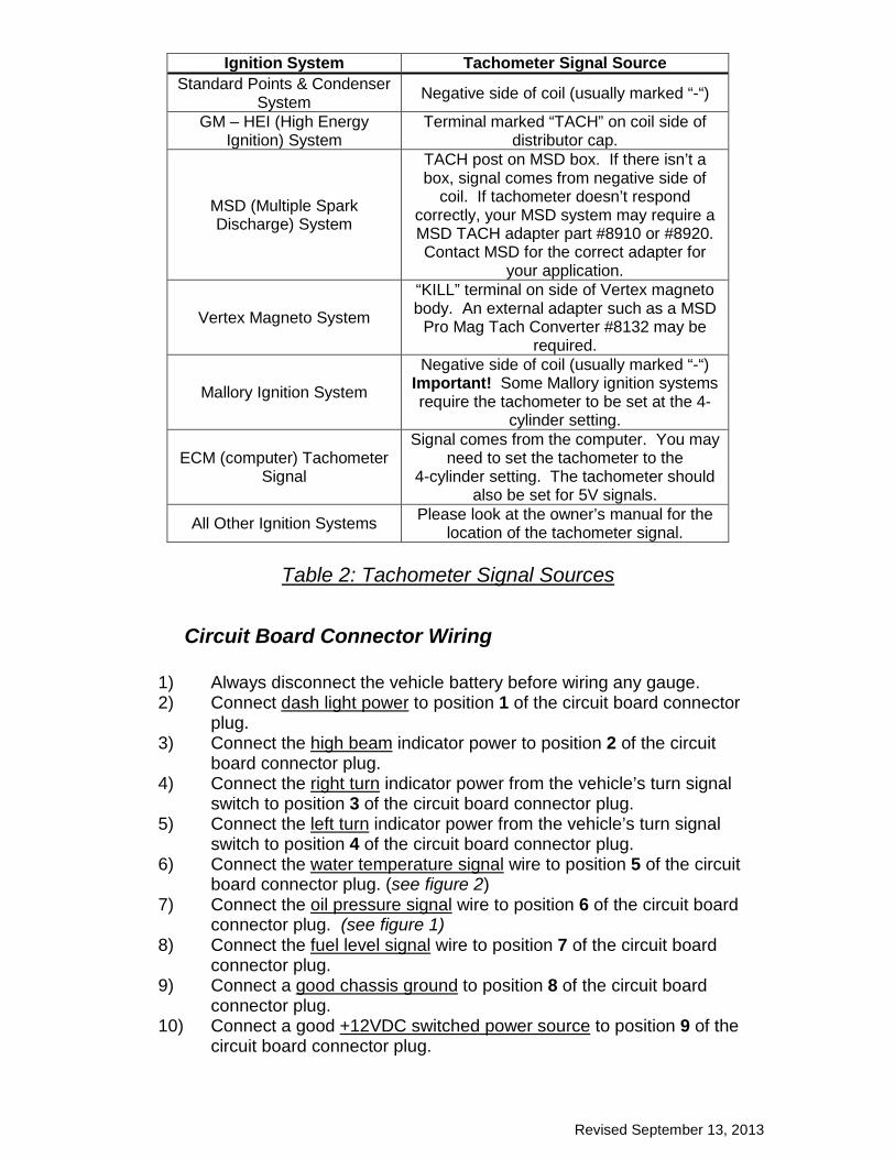
Oil Pressure Sender[SN52]
Ring Terminal
45° Elbow
Entension
Engine Block
Do not use teflon tape on the oil pressuresender or extension threads because thisinterferes with the sender's groundconnection.
To position 6 of circuit boardconnector plug.
Figure 1: Oil Pressure Sender Wiring
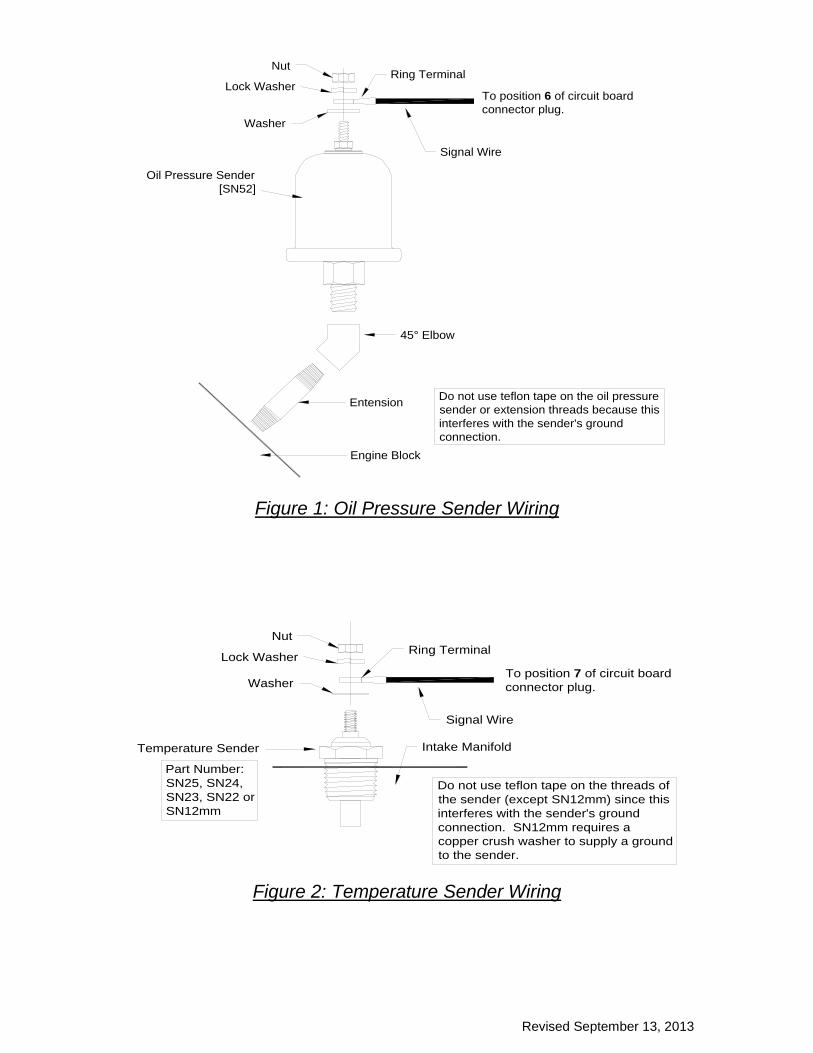
Signal Wire
Lock Washer
Nut
Washer
Ring Terminal
Intake ManifoldTemperature Sender
To position 7 of circuit boardconnector plug.
Do not use teflon tape on the threads ofthe sender (except SN12mm) since thisinterferes with the sender's groundconnection. SN12mm requires acopper crush washer to supply a groundto the sender.
Part Number:SN25, SN24,SN23, SN22 orSN12mm
Figure 2: Temperature Sender Wiring

Revised September 13, 2013
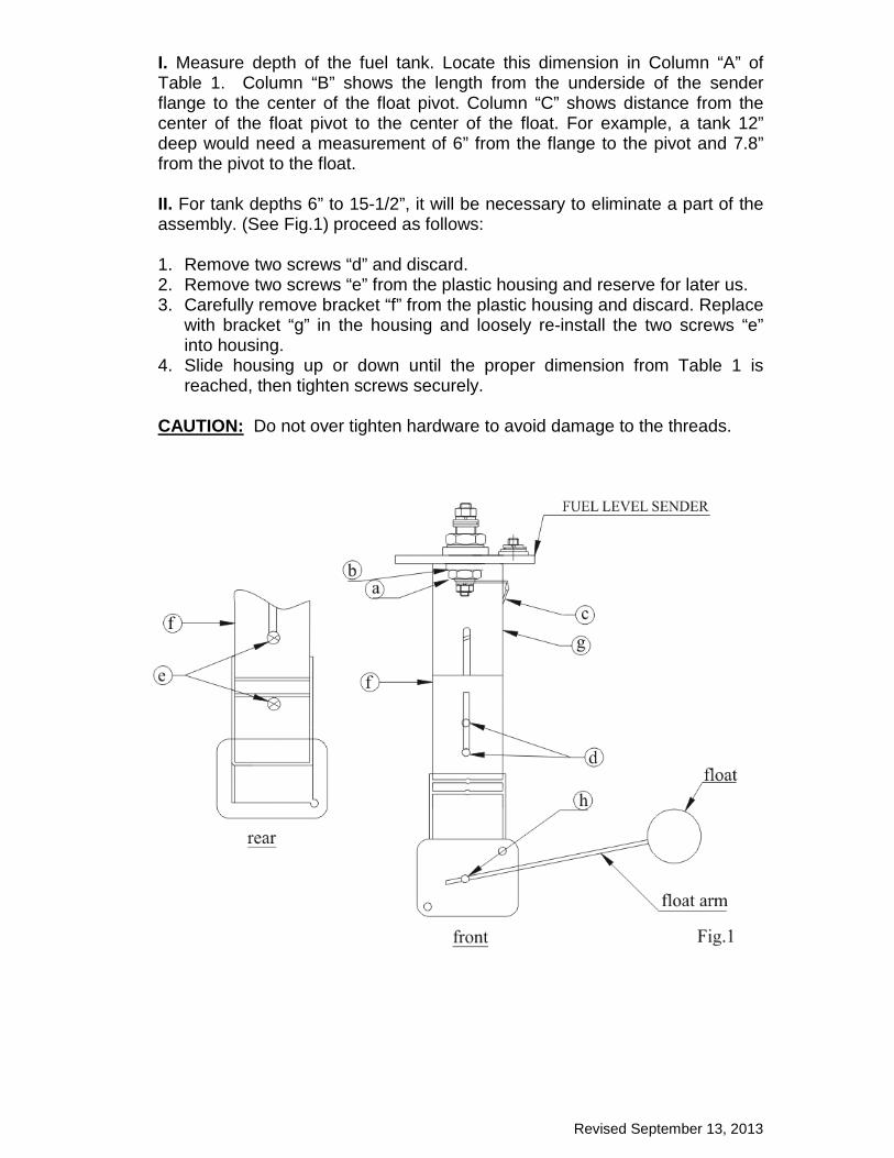
Fuel Level Sender Installation
ADJUSTABLE FUEL LEVEL SENDER KIT SN35 (240Ω-33Ω), SN36 (0Ω -30Ω), SN38 (0Ω -90Ω), SN39 (75Ω -10Ω) & SN40 (10Ω -180Ω)
A = Tank Depth , B = Float Pivot Depth , C = Float Arm Length (Dimensions in Inches)
A B C A B C A B C 6.0 3.0 3.5 12.0 6.0 7.8 18.0 9.0 12.0 6.5 3.25 3.8 12.5 6.25 8.1 18.5 9.25 12.3 7.0 3.5 4.2 13.0 6.5 8.5 19.0 9.5 12.6 7.5 3.75 4.5 13.5 6.75 8.9 19.5 9.75 12.9 8.0 4.0 4.9 14.0 7.0 9.3 20.0 10.0 13.4 8.5 4.25 5.3 14.5 7.25 9.6 20.5 10.25 13.8 9.0 4.5 5.6 15.0 7.5 10.0 21.0 10.5 14.2 9.5 4.75 6.0 15.5 7.75 10.4 10.0 5.0 6.4 16.0 8.0 10.7 10.5 5.25 6.7 16.5 8.25 11.0 11.0 5.5 7.1 17.0 8.5 11.4 11.5 5.75 7.4 17.5 8.75 11.8
TABLE 1
Revised September 13, 2013
I. Measure depth of the fuel tank. Locate this dimension in Column “A” of Table 1. Column “B” shows the length from the underside of the sender flange to the center of the float pivot. Column “C” shows distance from the center of the float pivot to the center of the float. For example, a tank 12” deep would need a measurement of 6” from the flange to the pivot and 7.8” from the pivot to the float. II. For tank depths 6” to 15-1/2”, it will be necessary to eliminate a part of the assembly. (See Fig.1) proceed as follows: 1. Remove two screws “d” and discard. 2. Remove two screws “e” from the plastic housing and reserve for later us. 3. Carefully remove bracket “f” from the plastic housing and discard. Replace
with bracket “g” in the housing and loosely re-install the two screws “e” into housing.
4. Slide housing up or down until the proper dimension from Table 1 is reached, then tighten screws securely.
CAUTION: Do not over tighten hardware to avoid damage to the threads.

Revised September 13, 2013
III. For tank depths of 16” to 21” no disassembly of the sender bracket is necessary.
1. Loosen two screws “d” and adjust the plastic housing up or down until the proper dimension from Table 1 is obtained, then retighten screws securely.
IV. To install the float assembly, loosen screw “h”, remove the short piece of rod, and discard. Insert the float rod until the proper length “c” from Table 1 is met, and then tighten the screw securely. Carefully cut off any excess rod with bolt cutter or similar tool, taking care not to damage the assembly. NOTE: Make sure the float is installed as shown in Fig.1. If installed backwards, the fuel gauge will indicate “full” when the tank is empty and “empty” when the tank is full. 1. Cut the sender bracket so it doesn’t extend lower than the black rheostat
assembly. The rheostat should be the lowest point of the fuel sender. 2. With the gasket in place below the flange, carefully feed the float arm and
sender body into the 1.697” (43mm) hole in the tank. Make certain the float arm has free motion within the tank. Using the sender flange as a template, locate the position of the five mounting holes. Use the supplied screws to mount into the tank with threaded inserts in place.
3. Insert fuel sender assembly into tank, align holes and thread in mounting screws. Check that all screws are secure to complete assembly.
4. Connect the center terminal of the sender to your fuel gauge’s signal terminal. Connect the off-center terminal to a good chassis ground.
AVOID OVERTIGHTENING.
Revised September 13, 2013
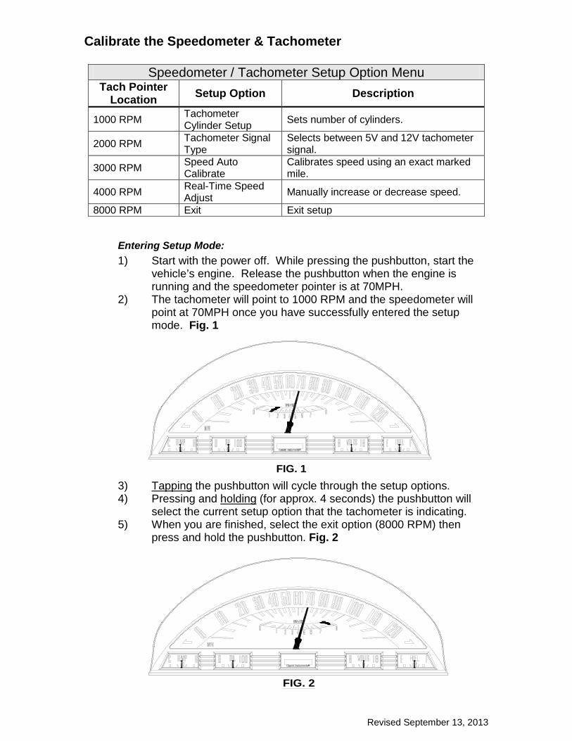
Calibrate the Speedometer & Tachometer
Speedometer / Tachometer Setup Option Menu Tach Pointer
Location Setup Option Description
1000 RPM Tachometer Cylinder Setup Sets number of cylinders.
2000 RPM Tachometer Signal Type
Selects between 5V and 12V tachometer signal.
3000 RPM Speed Auto Calibrate
Calibrates speed using an exact marked mile.
4000 RPM Real-Time Speed Adjust Manually increase or decrease speed.
8000 RPM Exit Exit setup
Entering Setup Mode: 1) Start with the power off. While pressing the pushbutton, start the
vehicle’s engine. Release the pushbutton when the engine is running and the speedometer pointer is at 70MPH.
2) The tachometer will point to 1000 RPM and the speedometer will point at 70MPH once you have successfully entered the setup mode. Fig. 1
3) Tapping the pushbutton will cycle through the setup options. 4) Pressing and holding (for approx. 4 seconds) the pushbutton will
select the current setup option that the tachometer is indicating. 5) When you are finished, select the exit option (8000 RPM) then
press and hold the pushbutton. Fig. 2
FIG. 1
FIG. 2
Revised September 13, 2013
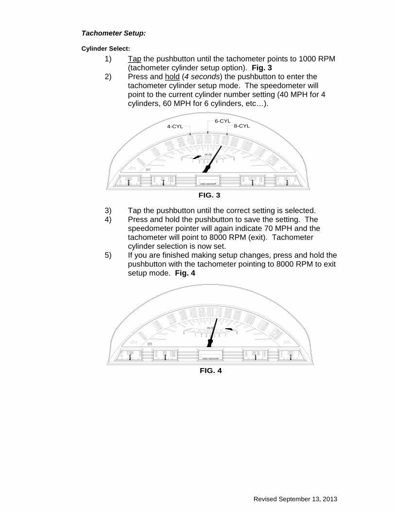
Tachometer Setup:
Cylinder Select: 1) Tap the pushbutton until the tachometer points to 1000 RPM
(tachometer cylinder setup option). Fig. 3 2) Press and hold (4 seconds) the pushbutton to enter the
tachometer cylinder setup mode. The speedometer will point to the current cylinder number setting (40 MPH for 4 cylinders, 60 MPH for 6 cylinders, etc…).
3) Tap the pushbutton until the correct setting is selected. 4) Press and hold the pushbutton to save the setting. The
speedometer pointer will again indicate 70 MPH and the tachometer will point to 8000 RPM (exit). Tachometer cylinder selection is now set.
5) If you are finished making setup changes, press and hold the pushbutton with the tachometer pointing to 8000 RPM to exit setup mode. Fig. 4
FIG. 3
8-CYL6-CYL
4-CYL
FIG. 4
Revised September 13, 2013
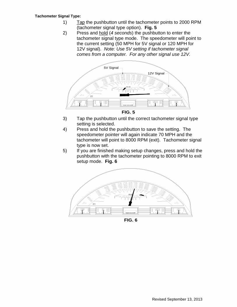
Tachometer Signal Type: 1) Tap the pushbutton until the tachometer points to 2000 RPM
(tachometer signal type option). Fig. 5 2) Press and hold (4 seconds) the pushbutton to enter the
tachometer signal type mode. The speedometer will point to the current setting (50 MPH for 5V signal or 120 MPH for 12V signal). Note: Use 5V setting if tachometer signal comes from a computer. For any other signal use 12V.
3) Tap the pushbutton until the correct tachometer signal type setting is selected.
4) Press and hold the pushbutton to save the setting. The speedometer pointer will again indicate 70 MPH and the tachometer will point to 8000 RPM (exit). Tachometer signal type is now set.
5) If you are finished making setup changes, press and hold the pushbutton with the tachometer pointing to 8000 RPM to exit setup mode. Fig. 6
FIG. 5
5V Signal
12V Signal
FIG. 6
Revised September 13, 2013
Speedometer Setup: There are two ways to calibrate the speedometer. Speed auto calibrate (using an exact marked mile) and real-time speed adjust (manually adjust speed up or down). It is recommended you use the speed auto calibrate option first and then make any fine tune adjustments using the real-time speed adjust option.
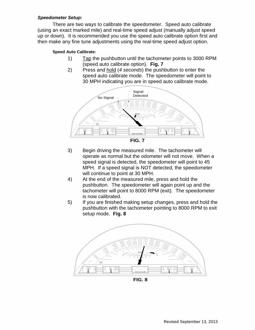
Speed Auto Calibrate: 1) Tap the pushbutton until the tachometer points to 3000 RPM
(speed auto calibrate option). Fig. 7 2) Press and hold (4 seconds) the pushbutton to enter the
speed auto calibrate mode. The speedometer will point to 30 MPH indicating you are in speed auto calibrate mode.
3) Begin driving the measured mile. The tachometer will operate as normal but the odometer will not move. When a speed signal is detected, the speedometer will point to 45 MPH. If a speed signal is NOT detected, the speedometer will continue to point at 30 MPH.
4) At the end of the measured mile, press and hold the pushbutton. The speedometer will again point up and the tachometer will point to 8000 RPM (exit). The speedometer is now calibrated.
5) If you are finished making setup changes, press and hold the pushbutton with the tachometer pointing to 8000 RPM to exit setup mode. Fig. 8
FIG. 7
No Signal
SignalDetected
FIG. 8
Revised September 13, 2013
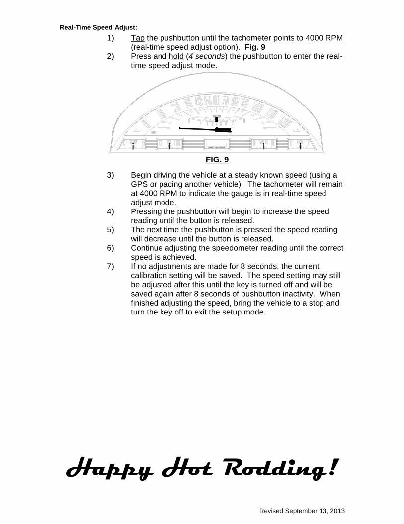
Real-Time Speed Adjust: 1) Tap the pushbutton until the tachometer points to 4000 RPM
(real-time speed adjust option). Fig. 9 2) Press and hold (4 seconds) the pushbutton to enter the real-
time speed adjust mode.
3) Begin driving the vehicle at a steady known speed (using a GPS or pacing another vehicle). The tachometer will remain at 4000 RPM to indicate the gauge is in real-time speed adjust mode.
4) Pressing the pushbutton will begin to increase the speed reading until the button is released.
5) The next time the pushbutton is pressed the speed reading will decrease until the button is released.
6) Continue adjusting the speedometer reading until the correct speed is achieved.
7) If no adjustments are made for 8 seconds, the current calibration setting will be saved. The speed setting may still be adjusted after this until the key is turned off and will be saved again after 8 seconds of pushbutton inactivity. When finished adjusting the speed, bring the vehicle to a stop and turn the key off to exit the setup mode.
Happy Hot Rodding!
FIG. 9